US7201737B2 - Treatment of vascular occlusions using elevated temperatures - Google Patents
Treatment of vascular occlusions using elevated temperaturesDownload PDFInfo
- Publication number
- US7201737B2 US7201737B2US11/046,209US4620905AUS7201737B2US 7201737 B2US7201737 B2US 7201737B2US 4620905 AUS4620905 AUS 4620905AUS 7201737 B2US7201737 B2US 7201737B2
- Authority
- US
- United States
- Prior art keywords
- catheter
- treatment site
- treatment
- elevated temperature
- temperature
- Prior art date
- Legal status (The legal status is an assumption and is not a legal conclusion. Google has not performed a legal analysis and makes no representation as to the accuracy of the status listed.)
- Expired - Lifetime
Links
Images


Classifications
- A—HUMAN NECESSITIES
- A61—MEDICAL OR VETERINARY SCIENCE; HYGIENE
- A61B—DIAGNOSIS; SURGERY; IDENTIFICATION
- A61B17/00—Surgical instruments, devices or methods
- A61B17/22—Implements for squeezing-off ulcers or the like on inner organs of the body; Implements for scraping-out cavities of body organs, e.g. bones; for invasive removal or destruction of calculus using mechanical vibrations; for removing obstructions in blood vessels, not otherwise provided for
- A61B17/22004—Implements for squeezing-off ulcers or the like on inner organs of the body; Implements for scraping-out cavities of body organs, e.g. bones; for invasive removal or destruction of calculus using mechanical vibrations; for removing obstructions in blood vessels, not otherwise provided for using mechanical vibrations, e.g. ultrasonic shock waves
- A61B17/22012—Implements for squeezing-off ulcers or the like on inner organs of the body; Implements for scraping-out cavities of body organs, e.g. bones; for invasive removal or destruction of calculus using mechanical vibrations; for removing obstructions in blood vessels, not otherwise provided for using mechanical vibrations, e.g. ultrasonic shock waves in direct contact with, or very close to, the obstruction or concrement
- A61B17/2202—Implements for squeezing-off ulcers or the like on inner organs of the body; Implements for scraping-out cavities of body organs, e.g. bones; for invasive removal or destruction of calculus using mechanical vibrations; for removing obstructions in blood vessels, not otherwise provided for using mechanical vibrations, e.g. ultrasonic shock waves in direct contact with, or very close to, the obstruction or concrement the ultrasound transducer being inside patient's body at the distal end of the catheter
- A—HUMAN NECESSITIES
- A61—MEDICAL OR VETERINARY SCIENCE; HYGIENE
- A61B—DIAGNOSIS; SURGERY; IDENTIFICATION
- A61B18/00—Surgical instruments, devices or methods for transferring non-mechanical forms of energy to or from the body
- A61B18/04—Surgical instruments, devices or methods for transferring non-mechanical forms of energy to or from the body by heating
- A61B2018/044—Surgical instruments, devices or methods for transferring non-mechanical forms of energy to or from the body by heating the surgical action being effected by a circulating hot fluid
- A61B2018/046—Surgical instruments, devices or methods for transferring non-mechanical forms of energy to or from the body by heating the surgical action being effected by a circulating hot fluid in liquid form
Definitions
- the present inventionrelates generally to treatment of vascular occlusions, and more specifically to treatment of vascular occlusions with elevated temperatures and a therapeutic compound.
- catheterscan be used to treat human blood vessels that have become partially or completely occluded by plaque, thrombi, emboli or other substances that reduce the blood carrying capacity of the vessel.
- the catheteris used to deliver solutions containing therapeutic compounds directly to the occlusion site.
- ultrasonic energy generated by the ultrasound assemblyis used to enhance the effect of the therapeutic compounds.
- Such a devicecan be used in the treatment of diseases such as peripheral arterial occlusion or deep vein thrombosis.
- the ultrasonic energyenhances treatment of the occlusion with therapeutic compounds such as urokinase, tissue plasminogen activator (“tPA”), recombinant tissue plasminogen activator (“rtPA”) and the like.
- therapeutic compoundssuch as urokinase, tissue plasminogen activator (“tPA”), recombinant tissue plasminogen activator (“rtPA”) and the like.
- the efficacy of therapeutic compounds in reducing or removing a vascular occlusioncan also be enhanced by increasing the temperature of the therapeutic compound that is provided at the treatment site. For example, it has been determined that treatment of lower limb ischemia progresses more rapidly when heated rtPA is used, than when room temperature rtPA is used. See Dimitrios K. Tsetis et al., “Potential Benefits From Heating the High-Dose rtPA Boluses Used in Catheter-Directed Thrombolysis for Acute/Subacute Lower Limb Ischemia”, J Endovasc Ther 10:739–744 (2003), the entire disclosure of which is hereby incorporated herein by reference.
- a methodfor treating a vascular obstruction at a treatment site within a patient's vasculature system.
- a catheteris advanced to the treatment site.
- the catheterincludes a treatment zone and a fluid delivery lumen that is coupled to an exit port within the treatment zone of the catheter.
- a therapeutic compoundis passed through the fluid delivery lumen and the exit port, such that the therapeutic compound is delivered to the treatment site.
- the treatment siteis heated to an elevated temperature.
- a cathetercomprises a tubular body having a drug delivery lumen terminating at a exit port within a treatment zone.
- a heating elementis positioned within the treatment zone.
- a temperature sensoris in the treatment zone.
- a control systemis configured to maintain the treatment zone at a an elevated temperature for a specified amount of time.
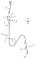
- FIG. 1is a schematic illustration of an ultrasonic catheter configured for insertion into large vessels of the human body.
- FIG. 2is a cross-sectional view of the ultrasonic catheter of FIG. 1 taken along line 2 — 2 .
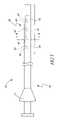
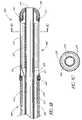
- FIG. 3is a schematic illustration of an elongate inner core configured to be positioned within the central lumen of the catheter illustrated in FIG. 2 .
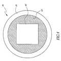
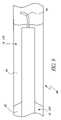
- FIG. 4is a cross-sectional view of the elongate inner core of FIG. 3 taken along line 4 — 4 .
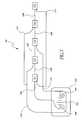
- FIG. 5is a schematic wiring diagram illustrating an exemplary technique for electrically connecting five groups of heating members to form an ultrasound assembly.
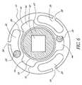
- FIG. 6illustrates the energy delivery section of the inner core of FIG. 4 positioned within the energy delivery section of the tubular body of FIG. 2 .
- FIG. 7illustrates a wiring diagram for connecting a plurality of temperature sensors with a common wire.
- FIG. 8Ais a schematic illustration of an ultrasonic catheter configured for insertion into small vessels of the human body.
- FIG. 8Bis a cross-sectional view of a distal end of an ultrasonic catheter configured for use within small vessels of a patient's vasculature.
- FIG. 8Cis a cross-sectional view of the ultrasound catheter taken through line 12 B— 12 B of FIG. 12A .
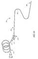
- FIG. 9is a side view of the distal end of an ultrasonic catheter positioned at a treatment site.
- FIG. 10is a block diagram of a feedback control system for use with an ultrasonic catheter.
- FIG. 11is a flowchart illustrating an exemplary technique for manipulating the temperature of a therapeutic compound at a treatment site.
- cathetersthat can be used to provide thermal energy and the therapeutic compound to the treatment site. Also disclosed are exemplary methods for using such catheters.
- therapeutic compoundrefers broadly, without limitation, and in addition to its ordinary meaning, to a drug, medicament, dissolution compound, genetic material or any other substance capable of effecting physiological functions. Additionally, a mixture includes substances such as these is also encompassed within this definition of “therapeutic compound”. Examples of therapeutic compounds include thrombolytic compounds, anti-thrombosis compounds, and other compounds used in the treatment of vascular occlusions, including compounds intended to prevent or reduce clot formation.
- exemplary therapeutic compoundsinclude, but are not limited to, heparin, urokinase, streptokinase, tPA, rtPA and BB-10153 (manufactured by British Biotech, Oxford, UK).
- ultrasonic energyAs used herein, the terms “ultrasonic energy”, “ultrasound” and “ultrasonic” refer broadly, without limitation, and in addition to their ordinary meaning, to mechanical energy transferred through longitudinal pressure or compression waves. Ultrasonic energy can be emitted as continuous or pulsed waves, depending on the parameters of a particular application. Additionally, ultrasonic energy can be emitted in waveforms having various shapes, such as sinusoidal waves, triangle waves, square waves, or other wave forms. Ultrasonic energy includes sound waves. In certain embodiments, the ultrasonic energy referred to herein has a frequency between about 20 kHz and about 20 MHz. For example, in one embodiment, the ultrasonic energy has a frequency between about 500 kHz and about 20 MHz.
- the ultrasonic energyhas a frequency between about 1 MHz and about 3 MHz. In yet another embodiment, the ultrasonic energy has a frequency of about 2 MHz. In certain embodiments described herein, the average acoustic power of the ultrasonic energy is between about 0.01 watts and 300 watts. In one embodiment, the average acoustic power is about 15 watts.
- the term “heating element”refers broadly, without limitation, and in addition to its ordinary meaning, to any apparatus capable of elevating the temperature of the treatment site.
- the heating elementcomprises an ultrasonic transducer, which converts electrical energy into ultrasonic energy and thermal energy.
- An exemplary ultrasonic transducer capable of generating ultrasonic energy from electrical energyis a piezoelectric ceramic oscillator.
- Piezoelectric ceramicstypically comprise a crystalline material, such as quartz, that changes shape when an electrical current is applied to the material. This change in shape, made oscillatory by an oscillating driving signal, creates ultrasonic sound waves.
- thermal energyis generated in two ways.
- the ultrasonic transducercoverts electrical energy to ultrasound energy imperfectly, some portion of the electrical energy is converted to heat.
- the ultrasound filed generated by the transduceris absorbed by the surrounding biological material producing a localized elevation of temperature.
- the heating elementcomprises a thermoelectric heater, such as, for example, an electrical resistive heaters.
- Other embodiments of an heating elementinclude, without limitation, RF emitters, lasers, conductive heaters, convective heaters and/or the delivery of a heated fluid to the treatment site.
- FIG. 1schematically illustrates a catheter 10 configured for use in the large vessels of a patient's anatomy.
- the catheter 10 illustrated in FIG. 1can be used to treat long segment peripheral arterial occlusions, such as those in the vascular system of the leg.
- the catheter 10generally includes a multi-component, elongate flexible tubular body 12 having a proximal region 14 and a distal region 15 .
- the tubular body 12includes a flexible treatment zone 18 located in the distal region 15 .
- the tubular body 12 and other components of the catheter 10can be manufactured in accordance with a variety of techniques known to an ordinarily skilled artisan. Suitable materials and dimensions can be readily selected based on the natural and anatomical dimensions of the treatment site and on the desired percutaneous access site.
- the tubular body proximal region 14comprises a material that has sufficient flexibility, kink resistance, rigidity and structural support to push the treatment zone 18 through the patient's. vasculature to a treatment site.
- materialsinclude, but are not limited to, extruded polytetrafluoroethylene (“PTFE”), polyethylenes (“PE”), polyamides and other similar materials.
- PTFEpolytetrafluoroethylene
- PEpolyethylenes
- polyamidespolyamides and other similar materials.
- the tubular body proximal region 14is reinforced by braiding, mesh or other constructions to provide increased kink resistance and ability to be pushed.
- nickel titanium or stainless steel wirescan be placed along or incorporated into the tubular body 12 to reduce kinking.
- the tubular body 12has an outside diameter between about 0.060 inches and about 0.075 inches. In another embodiment, the tubular body 12 has an outside diameter of about 0.071 inches. In certain embodiments, the tubular body 12 has an axial length of approximately 105 centimeters, although other lengths can be used in other applications.
- the tubular body 12is divided into at least three sections of varying stiffness.
- the first sectionwhich includes the proximal region 14 , has a relatively higher stiffness.
- the second sectionwhich is located in an intermediate region between the proximal region 14 and the distal region 15 , has a relatively lower stiffness. This configuration further facilitates movement and placement of the catheter 10 .
- the third sectionwhich includes the treatment zone 18 , has a relatively lower stiffness than the second section in spite of the presence of ultrasound radiating members which can be positioned therein.
- FIG. 2illustrates a cross section of the tubular body 12 taken along line 2 — 2 in FIG. 1 .
- three fluid delivery lumens 30are incorporated into the tubular body 12 .
- more or fewer fluid delivery lumenscan be incorporated into the tubular body 12 .
- the arrangement of the fluid delivery lumens 30provides a hollow central lumen 51 passing through the tubular body 12 .
- the cross-section of the tubular body 12is substantially constant along the length of the catheter 10 .
- substantially the same cross-sectionis present in both the proximal region 14 and the distal region 15 of the tubular body 12 , including the energy delivery section 18 .
- the central lumen 51has a minimum diameter greater than about 0.030 inches. In another embodiment, the central lumen 51 has a minimum diameter greater than about 0.037 inches. In an exemplary embodiment, the fluid delivery lumens 30 have dimensions of about 0.026 inches wide by about 0.0075 inches high, although other dimensions can be used in other embodiments.
- the central lumen 51extends through the length of the tubular body 12 . As illustrated in FIG. 1 , the central lumen 51 has a distal exit port 29 and a proximal access port 31 .
- the proximal access port 31forms part of the backend hub 33 , which is attached to the tubular body proximal region 14 .
- the backend hubalso includes a fluid fitting 46 , which is hydraulically connected to the central lumen 51 .
- the backend hub 33also includes a therapeutic compound inlet port 32 , which is hydraulically coupled to the fluid delivery lumens 30 , and which can also be hydraulically coupled to a source of therapeutic compound via a hub such as a Luer fitting.
- the central lumen 51is configured to receive an elongate inner core 34 , an exemplary embodiment of which is illustrated in FIG. 3 .
- the elongate inner core 34includes a proximal region 36 and a distal region 38 .
- a proximal hub 37is fitted on one end of the inner core proximal region 36 .
- One or more heating members 40are positioned within an inner core energy delivery section 41 that is located within the distal region 38 .
- the heating members 40form a heating assembly 42 , which will be described in greater detail below.
- the inner core 34has a cylindrical shape, with an outer diameter that permits the inner core 34 to be inserted into the central lumen 51 of the tubular body 12 via the proximal access port 31 .
- Suitable outer diameters of the inner core 34include, but are not limited to, between about 0.010 inches and about 0.100 inches.
- the outer diameter of the inner core 34is between about 0.020 inches and about 0.080 inches.
- the inner core 34has an outer diameter of about 0.035 inches.
- the inner core 34includes a cylindrical outer body 35 that houses the heating assembly 42 .
- the heating assembly 42includes wiring and heating members 40 , described in greater detail in below, such that the heating assembly 42 is capable elevating the temperature of the treatment site as described below.
- the heating assembly 42is electrically connected to the backend hub 33 , where the inner core 34 can be connected to a control system 100 via cable 45 (illustrated in FIG. 1 ).
- an electrically insulating potting material 43fills the inner core 34 , surrounding the heating assembly 42 , thus reducing or preventing movement of the heating assembly 42 with respect to the outer body 35 .
- the thickness of the outer body 35is between about 0.0002 inches and 0.010 inches. In another embodiment, the thickness of the outer body 35 is between about 0.0002 inches and 0.005 inches. In yet another embodiment, the thickness of the outer body 35 is about 0.0005 inches.
- the heating assembly 42includes a plurality of heating members 40 that are divided into one or more groups.
- FIG. 5is schematic wiring diagram illustrating one technique for connecting five groups of heating members 40 , in which the heat source members comprise an ultrasound element or a resistive heater.
- the heating assembly 42comprises five groups G 1 , G 2 , G 3 , G 4 , G 5 of heating members 40 that are electrically connected to each other.
- the five groupsare also electrically connected to the control system 100 .
- the control circuitry 100includes a voltage source 102 having a positive terminal 104 and a negative terminal 106 .
- the negative terminal 106is connected to common wire 108 , which connects the five groups G 1 –G 5 of heating members 40 in series.
- the positive terminal 104is connected to a plurality of lead wires 110 , which each connect to one of the five groups G 1 –G 5 of heating members 40 .
- FIG. 6illustrates the inner core 34 positioned within the tubular body 12 .
- the inner core 34can be slid within the central lumen 51 of the tubular body 12 , thereby allowing the inner core energy delivery section 41 to be positioned within the tubular body energy delivery section 18 .
- the tubular body 12is advanced to the treatment site over a guidewire. The guidewire may then be removed and the inner core 34 can be an be slid within the central lumen.
- FIG. 6further illustrates placement of fluid delivery ports 58 within the tubular body energy delivery section 18 .
- holes or slitsare formed from the fluid delivery lumen 30 through the tubular body 12 , thereby permitting fluid flow from the fluid delivery lumen 30 to the treatment site.
- a plurality of fluid delivery ports 58can be positioned axially along the tubular body 12 .
- a source of therapeutic compound coupled to the inlet port 32provides a hydraulic pressure which drives the therapeutic compound through the fluid delivery lumens 30 and out the fluid delivery ports 58 .
- fluid delivery ports 30By spacing the fluid delivery lumens 30 around the circumference of the tubular body 12 substantially evenly, as illustrated in FIG. 6 , a substantially uniform flow of therapeutic compound around the circumference of the tubular body 12 can be achieved. Additionally, the size, location and geometry of the fluid delivery ports 58 can be selected to provide uniform fluid flow from the fluid delivery ports 30 to the treatment site. For example, in one embodiment, fluid delivery ports closer to the proximal region of the energy delivery section 18 have smaller diameters than fluid delivery ports closer to the distal region of the energy delivery section 18 , thereby allowing uniform delivery of therapeutic compound in the energy delivery section.
- the fluid delivery ports 58have a diameter between about 0.0005 inches to about 0.0050 inches.
- the fluid delivery ports 58have a diameter between about 0.001 inches to about 0.005 inches in the proximal region of the energy delivery section 18 , and between about 0.005 inches to about 0.0020 inches in the distal region of the energy delivery section 18 .
- the increase in size between adjacent fluid delivery ports 58depends on a variety of factors, including the material comprising the tubular body 12 , and on the size of the fluid delivery lumen 30 .
- the fluid delivery ports 58can be created in the tubular body 12 by punching, drilling, burning or ablating (such as with a laser), or by other suitable methods. Therapeutic compound flow along the length of the tubular body 12 can also be increased by increasing the density of the fluid delivery ports 58 toward the distal region of the energy delivery section.
- a spatially nonuniform flow of therapeutic compound from the fluid delivery ports 58 to the treatment siteis to be provided.
- the size, location and geometry of the fluid delivery ports 58can be selected to provide such nonuniform fluid flow.
- placement of the inner core 34 within the tubular body 12further defines fluid lumens 44 .
- Fluid lumens 44are formed between an outer surface 39 of the inner core 34 and an inner surface 16 of the tubular body 12 .
- a cooling or heating fluidcan be introduced through the proximal access port 31 such that fluid flows through cooling fluid lumens 44 and out of the catheter 10 through distal exit port 29 (see FIG. 1 ).
- the fluid lumens 44are substantially evenly spaced around the circumference of the tubular body 12 (that is, at approximately 120° increments for a three-lumen configuration), thereby providing substantially uniform fluid flow over the inner core 34 .
- Such a configurationcan advantageously be used to remove or add thermal energy from the treatment site.
- the flow rate of the fluid and the power to the heat source assembly 42can be adjusted to maintain the temperature of the inner core energy delivery section 41 , or of the treatment site generally, within a desired range.
- the inner core 34can be rotated or moved within the tubular body 12 . Specifically, movement of the inner core 34 can be accomplished by maneuvering the proximal hub 37 while holding the backend hub 33 stationary.
- the inner core outer body 35is at least partially constructed from a material that provides enough structural support to permit movement of the inner core 34 within the tubular body 12 without kinking of the tubular body 12 .
- the inner core outer body 35comprises a material having the ability to transmit torque. Suitable materials for the inner core outer body 35 include, but are not limited to, polyimides, polyesters, polyurethanes, thermoplastic elastomers and braided polyimides.
- the fluid delivery lumens 30 and the fluid lumens 44are open at the distal end of the tubular body 12 , thereby allowing the therapeutic compound and the fluid to pass into the patient's vasculature at the distal exit port 29 .
- the fluid delivery lumens 30can be selectively occluded at the distal end of the tubular body 12 , thereby providing additional hydraulic pressure to drive the therapeutic compound out of the fluid delivery ports 58 .
- the inner core 34can be prevented from passing through the distal exit port 29 by providing the inner core 34 with a length that is less than the length of the tubular body 12 .
- a protrusionis formed within the tubular body 12 in the distal region 15 , thereby preventing the inner core 34 from passing through the distal exit port 29 .
- the catheter 10includes an occlusion device positioned at the distal exit port 29 .
- the occlusion devicehas a reduced inner diameter that can accommodate a guidewire, but that is less than the inner diameter of the central lumen 51 .
- suitable inner diameters for the occlusion deviceinclude, but are not limited to, between about 0.005 inches and about 0.050 inches.
- the occlusion devicehas a closed end, thus preventing cooling fluid from leaving the catheter 10 , and instead recirculating to the tubular body proximal region 14 .
- the tubular body 12includes one or more temperature sensors 20 that are positioned within the energy delivery section 18 .
- the tubular body proximal region 14includes a temperature sensor lead which can be incorporated into cable 45 (illustrated in FIG. 1 ).
- Suitable temperature sensorsinclude, but are not limited to, temperature sensing diodes, thermistors, thermocouples, resistance temperature detectors (“RTDs”) and fiber optic temperature sensors which use thermalchromic liquid crystals.
- Suitable temperature sensor 20 geometriesinclude, but are not limited to, a point, a patch or a stripe.
- the temperature sensors 20can be positioned within one or more of the fluid delivery lumens 30 , and/or within one or more of the cooling fluid lumens 44 . To maintain the axial position of the sensor 20 within the catheter 10 they may be attached to one or more elongated rigid members (not shown) that extend through the lumens 30 .
- FIG. 7illustrates an exemplary embodiment for electrically connecting the temperature sensors 20 .
- each temperature sensor 20is coupled to a common wire 61 and is associated with an individual return wire 62 .
- n+1 wiresare passed through the tubular body 12 to independently sense the temperature at n temperature sensors 20 .
- the temperature at a selected temperature sensor 20can be determined by closing a switch 64 to complete a circuit between the return wire 62 associated with the selected thermocouple and the common wire 61 .
- the temperaturecan be calculated from the voltage in the circuit using, for example, a sensing circuit 63 , which can be located within the external control circuitry 100 .
- the temperature sensors 20can be independently wired. In such embodiments, 2n wires are passed through the tubular body 12 to independently sense the temperature at n temperature sensors 20 . In still other embodiments, the flexibility of the tubular body 12 can be improved by using fiber optic based temperature sensors 20 . In such embodiments, flexibility can be improved because only n fiber optic members are used to sense the temperature at n independent temperature sensors 20 .
- FIGS. 8A–8Cillustrate an exemplary catheter 200 that is specifically configured to effectively navigate the small vessels of a patient's vasculature, such as the main and subsequent branches of the middle cerebral artery.
- an exemplary ultrasonic catheter configured for use in small vesselscomprises a multi-component tubular body 202 having a proximal region 204 and a distal region 206 .
- the catheter tubular body 202includes an outer sheath 208 that is positioned upon an inner core 210 .
- the outer sheath 208comprises extruded Pebax®, PTFE, polyetheretherketone (“PEEK”), PE, polyamides, braided polyamides and/or other similar materials.
- the outer sheath distal region 206is adapted for advancement through vessels having a small diameter, such as those in the vasculature of the brain.
- the outer sheath distal region 206has an outer diameter between about 2 French and about 5 French. In another embodiment, outer sheath distal region 206 has an outer diameter of about 2.8 French. In one exemplary embodiment, the outer sheath 208 has an axial length of approximately 150 centimeters.
- the outer sheath 208comprises a braided tubing formed of, for example, high or low density polyethylenes, urethanes, nylons, and the like. This configuration enhances the flexibility of the tubular body 202 .
- the outer sheath 208can be formed with a variable stiffness from the proximal to the distal end. To achieve this, a stiffening member may be included along the proximal end of the tubular body 202 .
- the inner core 210defines, at least in part, a delivery lumen 212 , which, in an exemplary embodiment, extends longitudinally along the catheter.
- the delivery lumen 212has a distal exit port 214 , and is hydraulically connected to a proximal access port (not shown). Similar to the large vessel ultrasonic catheter described herein, the proximal access port can be connected to a source of therapeutic compound or cooling/heating fluid that is to be delivered through the delivery lumen 212 .
- the delivery lumen 212is configured to receive a guide wire (not shown).
- the guidewirehas a diameter of between approximately 0.008 and approximately 0.012 inches. In another embodiment, the guidewire has a diameter of about 0.010 inches.
- the inner core 210comprises polyamide or a similar material which can optionally be braided to increase the flexibility of the tubular body 202 and reduce kinking and/or binding with the guidewire.
- the tubular body distal region 206includes a heating member 224 .
- the heating element 224may comprise any of a variety of components, such as, for example, thermoelectric devices, ultrasound transducers, etc.
- the heating element 224is configured as a hollow cylinder or otherwise generally disposed between the inner core 210 and the outer sheath 208 .
- the inner core 210extends generally through the lumen of the heating member 224 .
- the heating member 224may be secured to the inner core 210 in a suitable manner, such as using an adhesive.
- a potting materialcan also be used to further secure the heating member 224 to the inner core 210 .
- thermal energyis generated from electrical power supplied to the heating member 224 through a wires 226 , 228 that extend through the catheter body 202 .
- the wires 226 , 228cab be secured to the inner core 210 , lay along the inner core 210 and/or extend freely in the region 238 between the inner core 210 and the outer sheath 208 .
- the heating member 224comprises a transducer formed of a piezoelectric ceramic oscillator or a similar material
- the first wire 226may be connected to the hollow center of the ultrasound radiating member 224
- the second wire 228is connected to the outer periphery of the ultrasound radiating member 224 .
- the catheterfurther includes a sleeve 230 that is generally positioned about the heating member 224 .
- the sleeve 230is comprises a material that readily transmits thermal energy. Suitable materials for the sleeve 230 include, but are not limited to, polyolefins, polyimides, polyester and other materials having a relatively low absorbance of ultrasonic energy.
- the proximal end of the sleeve 230can be attached to the outer sheath 208 with an adhesive 232 .
- a shoulder 227 or notchcan be formed in the outer sheath 208 for attachment of the adhesive 232 thereto.
- the outer sheath 208 and the sleeve 230have substantially the same outer diameter.
- the distal end of the sleeve 230can be attached to a tip 234 .
- the tip 234is also attached to the distal end of the inner core 210 .
- the tip 234is between about 0.5 mm and about 4.0 mm long. In another embodiment, the tip is about 2.0 mm long.
- the tip 234is rounded in shape to reduce trauma or damage to tissue along the inner wall of a blood vessel or other body structure during advancement of the catheter to a treatment site.
- the catheterincludes at least one temperature sensor 236 in the tubular body distal region 206 .
- the temperature sensor 236can be positioned on or near the heating member 224 .
- Suitable temperature sensorsinclude but are not limited to, diodes, thermistors, thermocouples, RTDs and fiber optic temperature sensors that used thermalchromic liquid crystals.
- the temperature sensor 236is operatively connected to a control system via a control wire that extends through the tubular body 202 .
- the control boxincludes a feedback control system having the ability to monitor and control the power, voltage, current and phase supplied to the heating member 224 .
- the temperature along the relevant region of the cathetercan be monitored and controlled for optimal performance.
- the distal exit port 214 and heating member 224are generally positioned at the distal end 206 of the catheter to form a treatment zone 250 , which is configured to elevate the temperature of the treatment site and to deliver a therapeutic compound to the treatment site.
- the catheters 10 , 200 described abovecan be used to elevate the temperature of the treatment site. They may also be used to deliver a therapeutic compound to the treatment site.
- the elevated temperaturemay enhance the efficacy of certain therapeutic compounds by altering the structure of the therapeutic compound and/or effecting (e.g., accelerating) the chemical reactions at the treatment site.
- the elevated temperaturemay be used alone or in combination with ultrasound energy to enhance the therapeutic effect of a therapeutic compound.
- the therapeutic compoundis a compound that is used for the treatment of vascular occlusions, such as, for example, heparin, urokinase, streptokinase, tPA, rtPA and BB-10153 (manufactured by British Biotech, Oxford, UK) and/or other thrombolytic compounds or anti-thrombosis compounds.
- the heating element(s)may be used to raise the temperature of the treatment site, which includes the vascular occlusion that is targeted by the therapeutic compound. In this manner, the elevated temperature enhances the treatment and removal of the vascular occlusion. While thermal effects can be beneficial, it should be appreciated excessively high temperatures can cause tissue damage and death. Accordingly, in the preferred embodiments, the elevated temperature is kept within a safe limit, which, in one embodiment, is less than or equal to about 43° C.
- the catheter 10 , 100 of FIGS. 1–7 or 8 A– 8 Cmay be advanced over a guidewire 84 to a treatment site 88 that includes a obstruction or clot 90 .
- the guidewire 84is optionally directed through the clot 90 .
- the catheter 10 , 100is then advanced until the treatment zone is positioned at that treatment site. In this position, the treatment zone may be positioned partially or wholly within the clot 90 .
- the treatment zone or portions thereof including either the heating elements and/or the drug delivery port(s)may be positioned either upstream or downstream of the clot 90 .
- the guidewire 84is typically removed before the inner core 34 is advanced to the treatment site 88 .
- the heating element(s)may be used to elevate the temperature of the treatment site.
- the therapeutic compoundcan be delivered before, after, during or intermittently with the activation of the heating element(s).
- the treatment siteis maintained at an elevated (as compared to ambient conditions) temperature.
- the elevated temperatureis at least about 38° C.
- the elevated temperatureis at least about 40° C.
- the treatment siteis maintained within elevated temperature range, which in one embodiment is about from about 38 to about 43° C.
- the treatment siteis maintained at the elevated temperature for at least 5 minutes, in another embodiment at least 15 minutes, and in still another embodiment at least 30 minutes.
- the treatment siteis maintained at the elevated temperature until the clot 90 is substantially dissolved and/or blood flow through the vessel is substantially reestablished to normal conditions.
- the therapeutic compoundmay be delivered before, during and/or intermittingly during the treatment. Once the clot 90 has been sufficiently dissolved, the catheter can be withdrawn from the treatment site 88 .
- the elevated temperatureenhances the therapeutic effect of the therapeutic compound. In one embodiment, this results faster dissolution of clot. In another embodiment, the clot can be dissolved with less therapeutic compound as compared to treatment without the elevated temperature. Both embodiments are advantageous in that the therapeutic compound may have adverse side affects.
- the heat elementmay be any of a variety of components configured to deliver heat to a treatment site within a vascular system.
- the heat sourcecomprises an ultrasound transducer.
- thermal energyis generated in two ways. First, because the ultrasonic transducer coverts electrical energy to ultrasound energy imperfectly, some portion of the electrical energy is converted to heat.
- the ultrasound filed generated by the transduceris absorbed by the biological material surrounding the catheter producing a localized elevation of temperature.
- ultrasound energycan be applied to the treatment site along with the thermal energy.
- the heat sourcecomprises an modified ultrasound element that is configured to covert a larger percentage of electrical converted to heat as compared to the ultrasound elements optimized for the production of ultrasound energy.
- the heat sourcecomprises thermoelectric device, such as, a resistant heater through which heat is generated by passing an electrical current therethrough.
- a heated solutione.g., the therapeutic compound it self or a fluid passes through the lumen 44 of FIG. 6
- a RF elementcan be used to apply RF energy to raise the temperature of the treatment site.
- the catheters 10 , 200optionally include a control system capable of monitoring the temperature at the treatment site, and adjusting the operating parameters of the catheter accordingly.
- FIG. 100is one example of such a control system 300 , which his configured to control an embodiment in which the heating element 40 , 224 comprises a thermoelectric device (e.g., a resistive heater or an ultrasound element).
- the heating element 40 , 224comprises a thermoelectric device (e.g., a resistive heater or an ultrasound element).
- a thermoelectric devicee.g., a resistive heater or an ultrasound element
- the feedback control system 300includes an energy source 370 , power circuits 372 and a power calculation device 374 that is coupled to the heating element 40 , 224 .
- a temperature measurement device 376is coupled to the temperature sensor 20 , 236 in the catheter 10 , 200 .
- a processing unit 378is coupled to the power calculation device 374 , the power circuits 372 and a user interface and display 380 .
- the temperature at the temperature sensor 20 , 236is determined by the temperature measurement device 376 .
- the processing unit 378receives each determined temperature from the temperature measurement device 376 .
- the determined temperaturecan then be displayed to the user at the user interface and display 380 .
- the processing unit 378includes logic for generating a temperature control signal.
- the temperature control signalis proportional to the difference between the measured temperature and a desired temperature.
- the desired temperaturecan be determined by the user (as set at the user interface and display 380 ) or can be preset within the processing unit 378 .
- the temperature control signalis received by the power circuits 372 .
- the power circuits 372are configured to adjust the power level, voltage, phase, duty cycle and/or current of the electrical energy supplied to the heating elements 40 , 224 from the energy source 370 . For example, when the temperature control signal is above a particular level, the power supplied to the heat element is reduced in response to that temperature control signal. Similarly, when the temperature control signal is below a particular level, the power supplied to the heating source is increased in response to that temperature control signal.
- the processing unit 378monitors the temperature sensors 20 , 236 and produces another temperature control signal which is received by the power circuits 372 .
- the processing unit 378can comprise a digital or analog controller, such as a computer with software.
- the computercan include a central processing unit (“CPU”) coupled through a system bus.
- the user interface and display 380can include a mouse, a keyboard, a disk drive, a display monitor, a nonvolatile memory system, and/or other computer components.
- program memory and/or data memoryis also coupled to the bus.
- FIG. 11An exemplary control routine that can be utilized by the control system to maintain the temperature of the treatment site is illustrated in FIG. 11 .
- a therapeutic compound and thermal energyare delivered from a catheter located at the treatment site in an operational block 300 .
- the temperature of the treatment siteis monitored in an operational block 310 .
- the measured temperatureis compared to a specified operating range at decision points 320 , 330 . If the measured temperature is within the specified operating range, the treatment continues unchanged. However, if the measured temperature is above the specified range, the operation of the catheter is modified to reduce the temperature of the treatment site in an operational block 340 . Likewise, if the measured temperature is below the specified range, the operation of the catheter is modified to increase the temperature of the treatment site in an operational block 340 .
- the process of maintaining the elevated temperature of the treatment sitewill vary depending upon the nature of the heat heating element.
- the temperaturecan be controlled by increasing or decreasing the flow rate of a heating fluid or a cooling fluid.
- the flow and/or temperature of the therapeutic compoundmay be used to maintain the treatment site at the elevated temperature. increasing the temperature of the therapeutic compound provided to the therapeutic compound inlet port at the catheter proximal end. In still other embodiments, the temperature is decreased by simply reducing the power supplied to the heating elements.
- the thermal energy and the therapeutic compoundcan be delivered to the treatment site with different components.
- the therapeutic compoundis delivered through a drug delivery catheter advanced to the treatment site.
- the heat sourcemay be advanced to the treatment site via a second component, such as, a second separate catheter or an element (e.g., a guidewire or inner core) that is advanced through or along side the drug delivery catheter.
- the two componentsmay be positioned adjacent to each other during treatment or one of the components may be removed when not in use.
- the elevated temperature at treatment sitecan be generated from an energy source that is external to the body.
- ultrasound energycan be provided to the treatment site by applying an ultrasound transducer against the external surface tissue surrounding the target vessel.
- the external transducermay be applied against the head.
- the therapeutic compoundcan be applied to the treatment site via a drug delivery catheter.
- the treatment sitemay be heated using the external ultrasound techniques described above.
- the ultrasoundis absorbed the biological material producing a elevation of temperature at the treatment site.
- the drug delivery cathetermay be provided with a temperature sensor to monitor the temperature at the treatment site.
- the elevated temperaturemay be used in combination with therapeutic ultrasound therapy.
- the heating elementsmay comprise ultrasound radiating members and/or ultrasound radiating members may be integrated into the catheter described above.
- the suitable frequencies for the ultrasound radiating members 40include, but are not limited to, from about 20 kHz to about 20 MHz. In one embodiment, the frequency is between about 500 kHz and about 20 MHz, and in another embodiment the frequency is between about 1 MHz and about 3 MHz. In yet another embodiment, the ultrasound radiating members 40 are operated with a frequency of about 2 MHz.
- the heating element in the catheteris configured to heat the therapeutic compound as it flows through the catheter towards the treatment site.
- a therapeutic compound with an elevated temperaturecan be delivered to the treatment site.
- the elevated temperature of the compoundwill also elevate the temperature of the treatment site.
Landscapes
- Health & Medical Sciences (AREA)
- Surgery (AREA)
- Engineering & Computer Science (AREA)
- Life Sciences & Earth Sciences (AREA)
- Biomedical Technology (AREA)
- Nuclear Medicine, Radiotherapy & Molecular Imaging (AREA)
- Vascular Medicine (AREA)
- Orthopedic Medicine & Surgery (AREA)
- Mechanical Engineering (AREA)
- Heart & Thoracic Surgery (AREA)
- Medical Informatics (AREA)
- Molecular Biology (AREA)
- Animal Behavior & Ethology (AREA)
- General Health & Medical Sciences (AREA)
- Public Health (AREA)
- Veterinary Medicine (AREA)
- Media Introduction/Drainage Providing Device (AREA)
Abstract
Description
Claims (20)
Priority Applications (2)
| Application Number | Priority Date | Filing Date | Title |
|---|---|---|---|
| US11/046,209US7201737B2 (en) | 2004-01-29 | 2005-01-28 | Treatment of vascular occlusions using elevated temperatures |
| US11/685,643US20070161951A1 (en) | 2004-01-29 | 2007-03-13 | Treatment of vascular occlusions using elevated temperatures |
Applications Claiming Priority (3)
| Application Number | Priority Date | Filing Date | Title |
|---|---|---|---|
| US54003504P | 2004-01-29 | 2004-01-29 | |
| US56438204P | 2004-04-22 | 2004-04-22 | |
| US11/046,209US7201737B2 (en) | 2004-01-29 | 2005-01-28 | Treatment of vascular occlusions using elevated temperatures |
Related Child Applications (1)
| Application Number | Title | Priority Date | Filing Date |
|---|---|---|---|
| US11/685,643ContinuationUS20070161951A1 (en) | 2004-01-29 | 2007-03-13 | Treatment of vascular occlusions using elevated temperatures |
Publications (2)
| Publication Number | Publication Date |
|---|---|
| US20050240151A1 US20050240151A1 (en) | 2005-10-27 |
| US7201737B2true US7201737B2 (en) | 2007-04-10 |
Family
ID=35137454
Family Applications (2)
| Application Number | Title | Priority Date | Filing Date |
|---|---|---|---|
| US11/046,209Expired - LifetimeUS7201737B2 (en) | 2004-01-29 | 2005-01-28 | Treatment of vascular occlusions using elevated temperatures |
| US11/685,643AbandonedUS20070161951A1 (en) | 2004-01-29 | 2007-03-13 | Treatment of vascular occlusions using elevated temperatures |
Family Applications After (1)
| Application Number | Title | Priority Date | Filing Date |
|---|---|---|---|
| US11/685,643AbandonedUS20070161951A1 (en) | 2004-01-29 | 2007-03-13 | Treatment of vascular occlusions using elevated temperatures |
Country Status (1)
| Country | Link |
|---|---|
| US (2) | US7201737B2 (en) |
Cited By (6)
| Publication number | Priority date | Publication date | Assignee | Title |
|---|---|---|---|---|
| US20070161951A1 (en)* | 2004-01-29 | 2007-07-12 | Ekos Corporation | Treatment of vascular occlusions using elevated temperatures |
| US20090005734A1 (en)* | 2007-06-27 | 2009-01-01 | Tessaron Medical, Inc. | Systems and methods for delivering particles into patient body |
| US20090157069A1 (en)* | 2007-12-06 | 2009-06-18 | Curtis Tom | Systems and methods for thermal treatment of body tissue |
| WO2015074038A1 (en)* | 2013-11-18 | 2015-05-21 | Jeremy Stigall | Methods and devices for thrombus dispersal with cooling element |
| US10328290B2 (en) | 2012-08-03 | 2019-06-25 | Muffin Incorporated | Weeping balloon catheter with ultrasound element |
| US12319502B2 (en) | 2015-06-02 | 2025-06-03 | Symbotic Llc | Order fulfillment system |
Families Citing this family (3)
| Publication number | Priority date | Publication date | Assignee | Title |
|---|---|---|---|---|
| AU2012340381B2 (en) | 2011-11-15 | 2017-04-06 | Solventum Intellectual Properties Company | Medical dressings, systems, and methods with thermally- enhanced vapor transmission |
| GB2503673A (en) | 2012-07-03 | 2014-01-08 | Creo Medical Ltd | Electrosurgical device with convex under surface |
| US9687290B2 (en)* | 2012-10-02 | 2017-06-27 | Covidien Lp | Energy-based medical devices |
Citations (52)
| Publication number | Priority date | Publication date | Assignee | Title |
|---|---|---|---|---|
| US4754752A (en)* | 1986-07-28 | 1988-07-05 | Robert Ginsburg | Vascular catheter |
| US4921478A (en)* | 1988-02-23 | 1990-05-01 | C. R. Bard, Inc. | Cerebral balloon angioplasty system |
| JPH02180275A (en) | 1988-12-29 | 1990-07-13 | Toshiro Tachibana | Medicine injection tool having ultrasonic wave oscillation element |
| US5129883A (en)* | 1990-07-26 | 1992-07-14 | Michael Black | Catheter |
| US5158071A (en) | 1988-07-01 | 1992-10-27 | Hitachi, Ltd. | Ultrasonic apparatus for therapeutical use |
| US5197946A (en) | 1990-06-27 | 1993-03-30 | Shunro Tachibana | Injection instrument with ultrasonic oscillating element |
| US5269291A (en) | 1990-12-10 | 1993-12-14 | Coraje, Inc. | Miniature ultrasonic transducer for plaque ablation |
| US5318014A (en) | 1992-09-14 | 1994-06-07 | Coraje, Inc. | Ultrasonic ablation/dissolution transducer |
| US5362309A (en) | 1992-09-14 | 1994-11-08 | Coraje, Inc. | Apparatus and method for enhanced intravascular phonophoresis including dissolution of intravascular blockage and concomitant inhibition of restenosis |
| US5368036A (en) | 1992-10-20 | 1994-11-29 | Fuji Photo Optical Co., Ltd. | Ultrasound probe |
| US5380273A (en) | 1992-05-19 | 1995-01-10 | Dubrul; Will R. | Vibrating catheter |
| US5405322A (en)* | 1993-08-12 | 1995-04-11 | Boston Scientific Corporation | Method for treating aneurysms with a thermal source |
| US5558092A (en) | 1995-06-06 | 1996-09-24 | Imarx Pharmaceutical Corp. | Methods and apparatus for performing diagnostic and therapeutic ultrasound simultaneously |
| US5620479A (en) | 1992-11-13 | 1997-04-15 | The Regents Of The University Of California | Method and apparatus for thermal therapy of tumors |
| US5628728A (en) | 1995-05-31 | 1997-05-13 | Ekos Corporation | Medicine applying tool |
| US5630837A (en) | 1993-07-01 | 1997-05-20 | Boston Scientific Corporation | Acoustic ablation |
| US5713848A (en) | 1993-05-19 | 1998-02-03 | Dubrul; Will R. | Vibrating catheter |
| US5728062A (en) | 1995-11-30 | 1998-03-17 | Pharmasonics, Inc. | Apparatus and methods for vibratory intraluminal therapy employing magnetostrictive transducers |
| US5735811A (en) | 1995-11-30 | 1998-04-07 | Pharmasonics, Inc. | Apparatus and methods for ultrasonically enhanced fluid delivery |
| US5836896A (en) | 1996-08-19 | 1998-11-17 | Angiosonics | Method of inhibiting restenosis by applying ultrasonic energy |
| US5916192A (en) | 1991-01-11 | 1999-06-29 | Advanced Cardiovascular Systems, Inc. | Ultrasonic angioplasty-atherectomy catheter and method of use |
| WO1999034858A1 (en) | 1998-01-12 | 1999-07-15 | Georgia Tech Research Corporation | Assessment and control of acoustic tissue effects |
| US5935124A (en) | 1997-12-02 | 1999-08-10 | Cordis Webster, Inc. | Tip electrode with multiple temperature sensors |
| US5997497A (en) | 1991-01-11 | 1999-12-07 | Advanced Cardiovascular Systems | Ultrasound catheter having integrated drug delivery system and methods of using same |
| US6001069A (en) | 1997-05-01 | 1999-12-14 | Ekos Corporation | Ultrasound catheter for providing a therapeutic effect to a vessel of a body |
| US6024718A (en) | 1996-09-04 | 2000-02-15 | The Regents Of The University Of California | Intraluminal directed ultrasound delivery device |
| US6033397A (en)* | 1996-03-05 | 2000-03-07 | Vnus Medical Technologies, Inc. | Method and apparatus for treating esophageal varices |
| US6053868A (en) | 1997-04-24 | 2000-04-25 | Sulzer Osypka Gmbh | Apparatus for a cardiological therapy |
| US6078830A (en) | 1997-10-01 | 2000-06-20 | Ep Technologies, Inc. | Molded catheter distal end assembly and process for the manufacture thereof |
| US6096000A (en) | 1997-06-23 | 2000-08-01 | Ekos Corporation | Apparatus for transport of fluids across, into or from biological tissues |
| US6113558A (en) | 1997-09-29 | 2000-09-05 | Angiosonics Inc. | Pulsed mode lysis method |
| US6176842B1 (en) | 1995-03-08 | 2001-01-23 | Ekos Corporation | Ultrasound assembly for use with light activated drugs |
| US6190355B1 (en)* | 1992-01-10 | 2001-02-20 | Scimed Life Systems, Inc. | Heated perfusion balloon for reduction of restenosis |
| US6190315B1 (en) | 1998-01-08 | 2001-02-20 | Sontra Medical, Inc. | Sonophoretic enhanced transdermal transport |
| US6206831B1 (en) | 1999-01-06 | 2001-03-27 | Scimed Life Systems, Inc. | Ultrasound-guided ablation catheter and methods of use |
| US6210356B1 (en) | 1998-08-05 | 2001-04-03 | Ekos Corporation | Ultrasound assembly for use with a catheter |
| US6228046B1 (en) | 1997-06-02 | 2001-05-08 | Pharmasonics, Inc. | Catheters comprising a plurality of oscillators and methods for their use |
| US6231516B1 (en) | 1997-10-14 | 2001-05-15 | Vacusense, Inc. | Endoluminal implant with therapeutic and diagnostic capability |
| US20010025190A1 (en) | 1999-12-30 | 2001-09-27 | Pearl Technology Holdings, Llc | Face-lifting device |
| US6296619B1 (en) | 1998-12-30 | 2001-10-02 | Pharmasonics, Inc. | Therapeutic ultrasonic catheter for delivering a uniform energy dose |
| US6299597B1 (en)* | 1993-09-16 | 2001-10-09 | Scimed Life Systems, Inc. | Percutaneous repair of cardiovascular anomalies and repair compositions |
| US6387052B1 (en) | 1991-01-29 | 2002-05-14 | Edwards Lifesciences Corporation | Thermodilution catheter having a safe, flexible heating element |
| EP1252885A2 (en) | 1993-06-11 | 2002-10-30 | Imarx Pharmaceutical Corp. | Methods of preparing gas and gaseous precursor-filled microspheres |
| US6511478B1 (en) | 2000-06-30 | 2003-01-28 | Scimed Life Systems, Inc. | Medical probe with reduced number of temperature sensor wires |
| US6542767B1 (en) | 1999-11-09 | 2003-04-01 | Biotex, Inc. | Method and system for controlling heat delivery to a target |
| US6635017B1 (en) | 2000-02-09 | 2003-10-21 | Spentech, Inc. | Method and apparatus combining diagnostic ultrasound with therapeutic ultrasound to enhance thrombolysis |
| US20030220568A1 (en) | 2001-12-14 | 2003-11-27 | Hansmann Douglas R. | Blood flow reestablishment determination |
| US20040019318A1 (en) | 2001-11-07 | 2004-01-29 | Wilson Richard R. | Ultrasound assembly for use with a catheter |
| US20040024347A1 (en) | 2001-12-03 | 2004-02-05 | Wilson Richard R. | Catheter with multiple ultrasound radiating members |
| US20040049148A1 (en) | 2001-12-03 | 2004-03-11 | Oscar Rodriguez | Small vessel ultrasound catheter |
| US6723063B1 (en) | 1998-06-29 | 2004-04-20 | Ekos Corporation | Sheath for use with an ultrasound element |
| US6758857B2 (en) | 2000-11-13 | 2004-07-06 | Acmi Corporation | Treatment catheters with thermally insulated regions |
Family Cites Families (67)
| Publication number | Priority date | Publication date | Assignee | Title |
|---|---|---|---|---|
| US3433226A (en)* | 1965-07-21 | 1969-03-18 | Aeroprojects Inc | Vibratory catheterization apparatus and method of using |
| US4319580A (en)* | 1979-08-28 | 1982-03-16 | The Board Of Regents Of The University Of Washington | Method for detecting air emboli in the blood in an intracorporeal blood vessel |
| US4531943A (en)* | 1983-08-08 | 1985-07-30 | Angiomedics Corporation | Catheter with soft deformable tip |
| US4750902A (en)* | 1985-08-28 | 1988-06-14 | Sonomed Technology, Inc. | Endoscopic ultrasonic aspirators |
| US4808153A (en)* | 1986-11-17 | 1989-02-28 | Ultramed Corporation | Device for removing plaque from arteries |
| JPS63135179A (en)* | 1986-11-26 | 1988-06-07 | 立花 俊郎 | Subcataneous drug administration set |
| US5372138A (en)* | 1988-03-21 | 1994-12-13 | Boston Scientific Corporation | Acousting imaging catheters and the like |
| US4924863A (en)* | 1988-05-04 | 1990-05-15 | Mmtc, Inc. | Angioplastic method for removing plaque from a vas |
| US5178620A (en)* | 1988-06-10 | 1993-01-12 | Advanced Angioplasty Products, Inc. | Thermal dilatation catheter and method |
| US4920954A (en)* | 1988-08-05 | 1990-05-01 | Sonic Needle Corporation | Ultrasonic device for applying cavitation forces |
| US5021044A (en)* | 1989-01-30 | 1991-06-04 | Advanced Cardiovascular Systems, Inc. | Catheter for even distribution of therapeutic fluids |
| US4936281A (en)* | 1989-04-13 | 1990-06-26 | Everest Medical Corporation | Ultrasonically enhanced RF ablation catheter |
| US5399158A (en)* | 1990-05-31 | 1995-03-21 | The United States Of America As Represented By The Secretary Of The Army | Method of lysing thrombi |
| US5498238A (en)* | 1990-06-15 | 1996-03-12 | Cortrak Medical, Inc. | Simultaneous angioplasty and phoretic drug delivery |
| AU8074591A (en)* | 1990-06-15 | 1992-01-07 | Cortrak Medical, Inc. | Drug delivery apparatus and method |
| US5520189A (en)* | 1990-07-13 | 1996-05-28 | Coraje, Inc. | Intravascular ultrasound imaging guidewire |
| US5185071A (en)* | 1990-10-30 | 1993-02-09 | Board Of Regents, The University Of Texas System | Programmable electrophoresis with integrated and multiplexed control |
| US5304115A (en)* | 1991-01-11 | 1994-04-19 | Baxter International Inc. | Ultrasonic angioplasty device incorporating improved transmission member and ablation probe |
| US5307816A (en)* | 1991-08-21 | 1994-05-03 | Kabushiki Kaisha Toshiba | Thrombus resolving treatment apparatus |
| SE469778B (en)* | 1992-02-17 | 1993-09-13 | Bertil Olsson Enheten Foer Kar | Apparatus for arterial reperfusion by noninvasive ultrasound effect |
| DE4207463C2 (en)* | 1992-03-10 | 1996-03-28 | Siemens Ag | Arrangement for the therapy of tissue with ultrasound |
| US5295484A (en)* | 1992-05-19 | 1994-03-22 | Arizona Board Of Regents For And On Behalf Of The University Of Arizona | Apparatus and method for intra-cardiac ablation of arrhythmias |
| EP0619104B1 (en)* | 1992-09-16 | 2002-03-13 | Hitachi, Ltd. | Ultrasonic irradiation apparatus |
| US5733315A (en)* | 1992-11-13 | 1998-03-31 | Burdette; Everette C. | Method of manufacture of a transurethral ultrasound applicator for prostate gland thermal therapy |
| US5397293A (en)* | 1992-11-25 | 1995-03-14 | Misonix, Inc. | Ultrasonic device with sheath and transverse motion damping |
| US5390678A (en)* | 1993-10-12 | 1995-02-21 | Baxter International Inc. | Method and device for measuring ultrasonic activity in an ultrasound delivery system |
| DE69516444T2 (en)* | 1994-03-11 | 2001-01-04 | Intravascular Research Ltd., London | Ultrasonic transducer arrangement and method for its production |
| US5514092A (en)* | 1994-08-08 | 1996-05-07 | Schneider (Usa) Inc. | Drug delivery and dilatation-drug delivery catheters in a rapid exchange configuration |
| US5509896A (en)* | 1994-09-09 | 1996-04-23 | Coraje, Inc. | Enhancement of thrombolysis with external ultrasound |
| US5606974A (en)* | 1995-05-02 | 1997-03-04 | Heart Rhythm Technologies, Inc. | Catheter having ultrasonic device |
| US5603694A (en)* | 1995-10-17 | 1997-02-18 | Brown; Joe E. | Infusion coil apparatus and method for delivering fluid-based agents intravascularly |
| US5618275A (en)* | 1995-10-27 | 1997-04-08 | Sonex International Corporation | Ultrasonic method and apparatus for cosmetic and dermatological applications |
| US5725494A (en)* | 1995-11-30 | 1998-03-10 | Pharmasonics, Inc. | Apparatus and methods for ultrasonically enhanced intraluminal therapy |
| US20020045890A1 (en)* | 1996-04-24 | 2002-04-18 | The Regents Of The University O F California | Opto-acoustic thrombolysis |
| US6221038B1 (en)* | 1996-11-27 | 2001-04-24 | Pharmasonics, Inc. | Apparatus and methods for vibratory intraluminal therapy employing magnetostrictive transducers |
| US5876345A (en)* | 1997-02-27 | 1999-03-02 | Acuson Corporation | Ultrasonic catheter, system and method for two dimensional imaging or three-dimensional reconstruction |
| US6063069A (en)* | 1997-05-19 | 2000-05-16 | Micro Therapeutics Inc. | Method and apparatus for power lysis of a thrombus |
| US6562021B1 (en)* | 1997-12-22 | 2003-05-13 | Micrus Corporation | Variable stiffness electrically conductive composite, resistive heating catheter shaft |
| US6794369B2 (en)* | 1997-12-31 | 2004-09-21 | Pharmasonics | Methods, systems, and kits for intravascular nucleic acid delivery |
| EP1043949A2 (en)* | 1997-12-31 | 2000-10-18 | Pharmasonics, Inc. | Methods and systems for the inhibition of vascular hyperplasia |
| EP1044035A4 (en)* | 1997-12-31 | 2002-07-17 | Pharmasonics Inc | Methods, systems, and kits for intravascular nucleic acid delivery |
| US6561998B1 (en)* | 1998-04-07 | 2003-05-13 | Transvascular, Inc. | Transluminal devices, systems and methods for enlarging interstitial penetration tracts |
| AU758038B2 (en)* | 1998-06-30 | 2003-03-13 | Onda Corporation | Apparatus and method for inducing vibrations in a living body |
| US6059731A (en)* | 1998-08-19 | 2000-05-09 | Mayo Foundation For Medical Education And Research | Simultaneous side-and-end viewing underfluid catheter |
| AU1128600A (en)* | 1998-11-20 | 2000-06-13 | Joie P. Jones | Methods for selectively dissolving and removing materials using ultra-high frequency ultrasound |
| US6726698B2 (en)* | 1999-03-02 | 2004-04-27 | Sound Surgical Technologies Llc | Pulsed ultrasonic device and method |
| US6027515A (en)* | 1999-03-02 | 2000-02-22 | Sound Surgical Technologies Llc | Pulsed ultrasonic device and method |
| US6911026B1 (en)* | 1999-07-12 | 2005-06-28 | Stereotaxis, Inc. | Magnetically guided atherectomy |
| US6235024B1 (en)* | 1999-06-21 | 2001-05-22 | Hosheng Tu | Catheters system having dual ablation capability |
| US6361554B1 (en)* | 1999-06-30 | 2002-03-26 | Pharmasonics, Inc. | Methods and apparatus for the subcutaneous delivery of acoustic vibrations |
| US6579279B1 (en)* | 1999-09-24 | 2003-06-17 | Omnisonics Medical Technologies, Inc. | Steerable catheter device |
| US6196973B1 (en)* | 1999-09-30 | 2001-03-06 | Siemens Medical Systems, Inc. | Flow estimation using an ultrasonically modulated contrast agent |
| US6524251B2 (en)* | 1999-10-05 | 2003-02-25 | Omnisonics Medical Technologies, Inc. | Ultrasonic device for tissue ablation and sheath for use therewith |
| US6361500B1 (en)* | 2000-02-07 | 2002-03-26 | Scimed Life Systems, Inc. | Three transducer catheter |
| US20030069525A1 (en)* | 2000-03-08 | 2003-04-10 | Pharmasonics, Inc. | Methods, systems, and kits for plaque stabilization |
| US20020032394A1 (en)* | 2000-03-08 | 2002-03-14 | Axel Brisken | Methods, systems, and kits for plaque stabilization |
| US6508775B2 (en)* | 2000-03-20 | 2003-01-21 | Pharmasonics, Inc. | High output therapeutic ultrasound transducer |
| US6913581B2 (en)* | 2000-03-20 | 2005-07-05 | Paul D. Corl | High output therapeutic ultrasound transducer |
| US20020068869A1 (en)* | 2000-06-27 | 2002-06-06 | Axel Brisken | Drug delivery catheter with internal ultrasound receiver |
| US6503202B1 (en)* | 2000-06-29 | 2003-01-07 | Acuson Corp. | Medical diagnostic ultrasound system and method for flow analysis |
| US6733450B1 (en)* | 2000-07-27 | 2004-05-11 | Texas Systems, Board Of Regents | Therapeutic methods and apparatus for use of sonication to enhance perfusion of tissue |
| US6366719B1 (en)* | 2000-08-17 | 2002-04-02 | Miravant Systems, Inc. | Photodynamic therapy light diffuser |
| US6575922B1 (en)* | 2000-10-17 | 2003-06-10 | Walnut Technologies | Ultrasound signal and temperature monitoring during sono-thrombolysis therapy |
| US6537224B2 (en)* | 2001-06-08 | 2003-03-25 | Vermon | Multi-purpose ultrasonic slotted array transducer |
| JP2003087008A (en)* | 2001-07-02 | 2003-03-20 | Ngk Insulators Ltd | Multilayer dielectric filter |
| US7201737B2 (en)* | 2004-01-29 | 2007-04-10 | Ekos Corporation | Treatment of vascular occlusions using elevated temperatures |
| US20060116610A1 (en)* | 2004-11-30 | 2006-06-01 | Omnisonics Medical Technologies, Inc. | Apparatus and method for an ultrasonic medical device with variable frequency drive |
- 2005
- 2005-01-28USUS11/046,209patent/US7201737B2/ennot_activeExpired - Lifetime
- 2007
- 2007-03-13USUS11/685,643patent/US20070161951A1/ennot_activeAbandoned
Patent Citations (54)
| Publication number | Priority date | Publication date | Assignee | Title |
|---|---|---|---|---|
| US4754752A (en)* | 1986-07-28 | 1988-07-05 | Robert Ginsburg | Vascular catheter |
| US4921478A (en)* | 1988-02-23 | 1990-05-01 | C. R. Bard, Inc. | Cerebral balloon angioplasty system |
| US5158071A (en) | 1988-07-01 | 1992-10-27 | Hitachi, Ltd. | Ultrasonic apparatus for therapeutical use |
| JPH02180275A (en) | 1988-12-29 | 1990-07-13 | Toshiro Tachibana | Medicine injection tool having ultrasonic wave oscillation element |
| US5197946A (en) | 1990-06-27 | 1993-03-30 | Shunro Tachibana | Injection instrument with ultrasonic oscillating element |
| US5129883A (en)* | 1990-07-26 | 1992-07-14 | Michael Black | Catheter |
| US5269291A (en) | 1990-12-10 | 1993-12-14 | Coraje, Inc. | Miniature ultrasonic transducer for plaque ablation |
| US5916192A (en) | 1991-01-11 | 1999-06-29 | Advanced Cardiovascular Systems, Inc. | Ultrasonic angioplasty-atherectomy catheter and method of use |
| US5997497A (en) | 1991-01-11 | 1999-12-07 | Advanced Cardiovascular Systems | Ultrasound catheter having integrated drug delivery system and methods of using same |
| US6387052B1 (en) | 1991-01-29 | 2002-05-14 | Edwards Lifesciences Corporation | Thermodilution catheter having a safe, flexible heating element |
| US6190355B1 (en)* | 1992-01-10 | 2001-02-20 | Scimed Life Systems, Inc. | Heated perfusion balloon for reduction of restenosis |
| US5380273A (en) | 1992-05-19 | 1995-01-10 | Dubrul; Will R. | Vibrating catheter |
| US5318014A (en) | 1992-09-14 | 1994-06-07 | Coraje, Inc. | Ultrasonic ablation/dissolution transducer |
| US5474531A (en) | 1992-09-14 | 1995-12-12 | Coraje, Inc. | Apparatus and method for enhanced intravascular phonophoresis including dissolution of intravascular blockage and concomitant inhibition of restenosis |
| US5362309A (en) | 1992-09-14 | 1994-11-08 | Coraje, Inc. | Apparatus and method for enhanced intravascular phonophoresis including dissolution of intravascular blockage and concomitant inhibition of restenosis |
| US5368036A (en) | 1992-10-20 | 1994-11-29 | Fuji Photo Optical Co., Ltd. | Ultrasound probe |
| US5620479A (en) | 1992-11-13 | 1997-04-15 | The Regents Of The University Of California | Method and apparatus for thermal therapy of tumors |
| US5713848A (en) | 1993-05-19 | 1998-02-03 | Dubrul; Will R. | Vibrating catheter |
| EP1252885A2 (en) | 1993-06-11 | 2002-10-30 | Imarx Pharmaceutical Corp. | Methods of preparing gas and gaseous precursor-filled microspheres |
| US5630837A (en) | 1993-07-01 | 1997-05-20 | Boston Scientific Corporation | Acoustic ablation |
| US5405322A (en)* | 1993-08-12 | 1995-04-11 | Boston Scientific Corporation | Method for treating aneurysms with a thermal source |
| US6299597B1 (en)* | 1993-09-16 | 2001-10-09 | Scimed Life Systems, Inc. | Percutaneous repair of cardiovascular anomalies and repair compositions |
| US6176842B1 (en) | 1995-03-08 | 2001-01-23 | Ekos Corporation | Ultrasound assembly for use with light activated drugs |
| US5628728A (en) | 1995-05-31 | 1997-05-13 | Ekos Corporation | Medicine applying tool |
| US5558092A (en) | 1995-06-06 | 1996-09-24 | Imarx Pharmaceutical Corp. | Methods and apparatus for performing diagnostic and therapeutic ultrasound simultaneously |
| US6287271B1 (en) | 1995-06-07 | 2001-09-11 | Bacchus Vascular, Inc. | Motion catheter |
| US5728062A (en) | 1995-11-30 | 1998-03-17 | Pharmasonics, Inc. | Apparatus and methods for vibratory intraluminal therapy employing magnetostrictive transducers |
| US5735811A (en) | 1995-11-30 | 1998-04-07 | Pharmasonics, Inc. | Apparatus and methods for ultrasonically enhanced fluid delivery |
| US6033397A (en)* | 1996-03-05 | 2000-03-07 | Vnus Medical Technologies, Inc. | Method and apparatus for treating esophageal varices |
| US5836896A (en) | 1996-08-19 | 1998-11-17 | Angiosonics | Method of inhibiting restenosis by applying ultrasonic energy |
| US6024718A (en) | 1996-09-04 | 2000-02-15 | The Regents Of The University Of California | Intraluminal directed ultrasound delivery device |
| US6053868A (en) | 1997-04-24 | 2000-04-25 | Sulzer Osypka Gmbh | Apparatus for a cardiological therapy |
| US6001069A (en) | 1997-05-01 | 1999-12-14 | Ekos Corporation | Ultrasound catheter for providing a therapeutic effect to a vessel of a body |
| US6228046B1 (en) | 1997-06-02 | 2001-05-08 | Pharmasonics, Inc. | Catheters comprising a plurality of oscillators and methods for their use |
| US6096000A (en) | 1997-06-23 | 2000-08-01 | Ekos Corporation | Apparatus for transport of fluids across, into or from biological tissues |
| US6113558A (en) | 1997-09-29 | 2000-09-05 | Angiosonics Inc. | Pulsed mode lysis method |
| US6078830A (en) | 1997-10-01 | 2000-06-20 | Ep Technologies, Inc. | Molded catheter distal end assembly and process for the manufacture thereof |
| US6231516B1 (en) | 1997-10-14 | 2001-05-15 | Vacusense, Inc. | Endoluminal implant with therapeutic and diagnostic capability |
| US5935124A (en) | 1997-12-02 | 1999-08-10 | Cordis Webster, Inc. | Tip electrode with multiple temperature sensors |
| US6190315B1 (en) | 1998-01-08 | 2001-02-20 | Sontra Medical, Inc. | Sonophoretic enhanced transdermal transport |
| WO1999034858A1 (en) | 1998-01-12 | 1999-07-15 | Georgia Tech Research Corporation | Assessment and control of acoustic tissue effects |
| US6723063B1 (en) | 1998-06-29 | 2004-04-20 | Ekos Corporation | Sheath for use with an ultrasound element |
| US6210356B1 (en) | 1998-08-05 | 2001-04-03 | Ekos Corporation | Ultrasound assembly for use with a catheter |
| US6296619B1 (en) | 1998-12-30 | 2001-10-02 | Pharmasonics, Inc. | Therapeutic ultrasonic catheter for delivering a uniform energy dose |
| US6206831B1 (en) | 1999-01-06 | 2001-03-27 | Scimed Life Systems, Inc. | Ultrasound-guided ablation catheter and methods of use |
| US6542767B1 (en) | 1999-11-09 | 2003-04-01 | Biotex, Inc. | Method and system for controlling heat delivery to a target |
| US20010025190A1 (en) | 1999-12-30 | 2001-09-27 | Pearl Technology Holdings, Llc | Face-lifting device |
| US6635017B1 (en) | 2000-02-09 | 2003-10-21 | Spentech, Inc. | Method and apparatus combining diagnostic ultrasound with therapeutic ultrasound to enhance thrombolysis |
| US6511478B1 (en) | 2000-06-30 | 2003-01-28 | Scimed Life Systems, Inc. | Medical probe with reduced number of temperature sensor wires |
| US6758857B2 (en) | 2000-11-13 | 2004-07-06 | Acmi Corporation | Treatment catheters with thermally insulated regions |
| US20040019318A1 (en) | 2001-11-07 | 2004-01-29 | Wilson Richard R. | Ultrasound assembly for use with a catheter |
| US20040024347A1 (en) | 2001-12-03 | 2004-02-05 | Wilson Richard R. | Catheter with multiple ultrasound radiating members |
| US20040049148A1 (en) | 2001-12-03 | 2004-03-11 | Oscar Rodriguez | Small vessel ultrasound catheter |
| US20030220568A1 (en) | 2001-12-14 | 2003-11-27 | Hansmann Douglas R. | Blood flow reestablishment determination |
Cited By (6)
| Publication number | Priority date | Publication date | Assignee | Title |
|---|---|---|---|---|
| US20070161951A1 (en)* | 2004-01-29 | 2007-07-12 | Ekos Corporation | Treatment of vascular occlusions using elevated temperatures |
| US20090005734A1 (en)* | 2007-06-27 | 2009-01-01 | Tessaron Medical, Inc. | Systems and methods for delivering particles into patient body |
| US20090157069A1 (en)* | 2007-12-06 | 2009-06-18 | Curtis Tom | Systems and methods for thermal treatment of body tissue |
| US10328290B2 (en) | 2012-08-03 | 2019-06-25 | Muffin Incorporated | Weeping balloon catheter with ultrasound element |
| WO2015074038A1 (en)* | 2013-11-18 | 2015-05-21 | Jeremy Stigall | Methods and devices for thrombus dispersal with cooling element |
| US12319502B2 (en) | 2015-06-02 | 2025-06-03 | Symbotic Llc | Order fulfillment system |
Also Published As
| Publication number | Publication date |
|---|---|
| US20070161951A1 (en) | 2007-07-12 |
| US20050240151A1 (en) | 2005-10-27 |
Similar Documents
| Publication | Publication Date | Title |
|---|---|---|
| US20230263545A1 (en) | Method and apparatus for treatment of intracranial hemorrhages | |
| US7341569B2 (en) | Treatment of vascular occlusions using ultrasonic energy and microbubbles | |
| US6979293B2 (en) | Blood flow reestablishment determination | |
| US7771372B2 (en) | Ultrasonic catheter with axial energy field | |
| EP1091699B1 (en) | Sheath for use with an ultrasound element | |
| US9943675B1 (en) | Ultrasonic catheter power control | |
| US6921371B2 (en) | Ultrasound radiating members for catheter | |
| US20100063413A1 (en) | Lysis Indication | |
| US20050209578A1 (en) | Ultrasonic catheter with segmented fluid delivery | |
| US8192363B2 (en) | Catheter with multiple ultrasound radiating members | |
| US20070161951A1 (en) | Treatment of vascular occlusions using elevated temperatures | |
| US20050215946A1 (en) | Method and apparatus for detecting vascular conditions with a catheter | |
| US20100063414A1 (en) | Lysis Indication | |
| US11458290B2 (en) | Ultrasound system |
Legal Events
| Date | Code | Title | Description |
|---|---|---|---|
| AS | Assignment | Owner name:EKOS CORPORATION, WASHINGTON Free format text:ASSIGNMENT OF ASSIGNORS INTEREST;ASSIGNORS:HANSMANN, DOUGLAS R.;RULE, PETER R.;REEL/FRAME:016300/0621;SIGNING DATES FROM 20050516 TO 20050517 | |
| STCF | Information on status: patent grant | Free format text:PATENTED CASE | |
| AS | Assignment | Owner name:HERCULES TECHNOLOGY II, L.P., CALIFORNIA Free format text:SECURITY AGREEMENT;ASSIGNOR:EKOS CORPORATION;REEL/FRAME:019550/0881 Effective date:20070524 Owner name:HERCULES TECHNOLOGY II, L.P.,CALIFORNIA Free format text:SECURITY AGREEMENT;ASSIGNOR:EKOS CORPORATION;REEL/FRAME:019550/0881 Effective date:20070524 | |
| FPAY | Fee payment | Year of fee payment:4 | |
| AS | Assignment | Owner name:EKOS CORPORATION, WASHINGTON Free format text:RELEASE BY SECURED PARTY;ASSIGNOR:HERCULES TECHNOLOGY II, L.P.;REEL/FRAME:030421/0867 Effective date:20101021 | |
| FEPP | Fee payment procedure | Free format text:PAT HOLDER NO LONGER CLAIMS SMALL ENTITY STATUS, ENTITY STATUS SET TO UNDISCOUNTED (ORIGINAL EVENT CODE: STOL); ENTITY STATUS OF PATENT OWNER: LARGE ENTITY | |
| FPAY | Fee payment | Year of fee payment:8 | |
| MAFP | Maintenance fee payment | Free format text:PAYMENT OF MAINTENANCE FEE, 12TH YEAR, LARGE ENTITY (ORIGINAL EVENT CODE: M1553); ENTITY STATUS OF PATENT OWNER: LARGE ENTITY Year of fee payment:12 | |
| AS | Assignment | Owner name:BOSTON SCIENTIFIC SCIMED, INC., MINNESOTA Free format text:ASSIGNMENT OF ASSIGNORS INTEREST;ASSIGNOR:EKOS LLC;REEL/FRAME:059847/0748 Effective date:20191231 Owner name:EKOS LLC, WASHINGTON Free format text:CHANGE OF NAME;ASSIGNOR:EKOS CORPORATION;REEL/FRAME:059320/0752 Effective date:20191209 |