US7201476B2 - Inkjet printhead with bubble handling properties - Google Patents
Inkjet printhead with bubble handling propertiesDownload PDFInfo
- Publication number
- US7201476B2 US7201476B2US11/008,834US883404AUS7201476B2US 7201476 B2US7201476 B2US 7201476B2US 883404 AUS883404 AUS 883404AUS 7201476 B2US7201476 B2US 7201476B2
- Authority
- US
- United States
- Prior art keywords
- outlet
- inkjet printhead
- sectional area
- feed
- plane
- Prior art date
- Legal status (The legal status is an assumption and is not a legal conclusion. Google has not performed a legal analysis and makes no representation as to the accuracy of the status listed.)
- Expired - Lifetime, expires
Links
Images

Classifications
- B—PERFORMING OPERATIONS; TRANSPORTING
- B41—PRINTING; LINING MACHINES; TYPEWRITERS; STAMPS
- B41J—TYPEWRITERS; SELECTIVE PRINTING MECHANISMS, i.e. MECHANISMS PRINTING OTHERWISE THAN FROM A FORME; CORRECTION OF TYPOGRAPHICAL ERRORS
- B41J2/00—Typewriters or selective printing mechanisms characterised by the printing or marking process for which they are designed
- B41J2/005—Typewriters or selective printing mechanisms characterised by the printing or marking process for which they are designed characterised by bringing liquid or particles selectively into contact with a printing material
- B41J2/01—Ink jet
- B41J2/17—Ink jet characterised by ink handling
- B41J2/175—Ink supply systems ; Circuit parts therefor
- B41J2/17503—Ink cartridges
- B41J2/17513—Inner structure
Definitions
- Conventional inkjet printerstypically include one or more printheads in which ink is stored. Such printheads have one or more ink reservoirs in fluid communication with nozzles through which ink exits the printhead toward a print medium. In many cases, the nozzles are located in one or more nozzle plates coupled to a body of the printhead. Each nozzle plate can be or include a chip having heat transducers that heat and vaporize the ink, thereby ejecting the ink from the nozzles.
- air bubbles in the inkcan block at least a portion of ink flow through the printhead, and in some cases can cause sufficient flow restriction to deprime at least some of the printhead nozzles.
- inkflows along a fluid path extending from an ink reservoir and through a filter tower, an ink via, and a short feed tube feeding ink to the nozzles.
- the short feed tubeis typically completely open to the ink via and has no features inhibiting bubble blockage of the fluid path.
- the fluid pathextends from an ink reservoir and through a filter tower, an ink via, and a narrow feed tube that is not completely open to the ink via. Bubbles can accumulate in the narrow feed tubes to cause depriming.
- an inkjet printheadcomprising a housing having an ink reservoir; an outer surface of the housing; an ink feed at least partially defining a fluid path extending from the ink reservoir toward the outer surface; a chip feed having an inlet in fluid communication with the ink feed and an outlet in fluid communication with the outer surface; a first plane at the inlet defining a first cross sectional area of the chip feed at the inlet, the first plane separating the ink feed from the chip feed; a second plane in which the outlet lies, the second plane defining a second cross sectional area of the chip feed at the outlet, the second cross sectional area being substantially greater than the first cross-sectional area; and at least one of a projection and a recess positioned along a transition surface of the chip feed between the inlet and the outlet.
- an inkjet printheadcomprises a housing having an ink reservoir; an outer surface of the housing; an ink feed at least partially defining a fluid path extending from the ink reservoir toward the outer surface; a chip feed positioned to fluidly couple the ink feed and the outer surface, the chip feed defining a chamber having a roof elongated in a first direction and an outlet elongated substantially in the first direction; and at least one of a projection and a recess extending along at least part of the roof in the first direction.
- an inkjet printheadcomprising: a housing having an ink reservoir; an outer surface of the housing; an ink feed at least partially defining a fluid path extending from the ink reservoir toward the outer surface; an chip feed having an inlet in fluid communication with the ink feed and an outlet in fluid communication with the outer surface; a first plane at the inlet, the first plane defining a first cross sectional area of the chip feed at the inlet, the first cross-sectional area defined at least in part by a first width and a first length greater than the first width; a second plane in which the outlet lies, the second plane defining a second cross-sectional area of the chip feed at the outlet, the second cross-sectional area defined at least in part by a second width and a second length greater than the second width, the second length being substantially greater than the first length; and at least one of a projection and a recess extending along a transition surface of the chip feed between the inlet and the outlet.
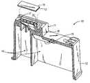
- FIG. 1is cross-sectional perspective view of an embodiment of an inkjet printhead shown upside down with respect to a typical operating position.
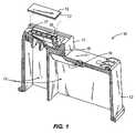
- FIG. 2is a close-up perspective view of the inkjet printhead of FIG. 1 .
- FIG. 2 ais a close-up perspective view of an inkjet printhead according to a second embodiment of the present invention.
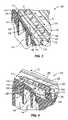
- FIG. 3is a close-up perspective view of an inkjet printhead according to a third embodiment of the present invention.
- FIG. 4is a close-up perspective view of an inkjet printhead according to a fourth embodiment of the present invention.
- FIGS. 1 and 2illustrate an inkjet printhead 10 according to an embodiment of the present invention.
- the printhead 10includes a housing 12 that defines a nosepiece 11 and one or more ink reservoirs 14 .
- the housing 12can have other shapes, some of which have no identifiable nosepiece.
- the housing 12can be constructed of a variety of materials, including without limitation polymers, metals, ceramics, composites, and the like.
- Each ink reservoir 14contains ink, which in some cases can at least partially saturate an insert (not shown) received within the reservoir 14 .
- the term “ink”can refer to at least one of inks, dyes, stains, pigments, colorants, tints, a combination thereof, and any other material that can be used by inkjet printers to print matter upon a printing medium.
- the term “printing medium”can refer to at least one of paper (including without limitation stock paper, stationary, tissue paper, homemade paper, and the like), film, tape, photo paper, a combination thereof, and any other medium upon which material can be printed by an inkjet printer.
- the printhead 10has a chip 13 and a nozzle plate 15 for ejecting ink to a printing medium.
- the term “chip”refers to one or more layers of material having one or more arrays of heat transducers that can correspond to fluid channels, firing chambers and nozzles (“flow features”) in one or more layers of a nozzle plate 15 .
- the chip 13can be in fluid communication with the nozzle plate 15 , such as one or more ink slots in the chip 13 in fluid communication with the flow features of the nozzle plate 15 .
- one or more layers of the chip 13are in fluid communication with one or more ink reservoirs 14 in the housing 12 .
- the chip 13 and the nozzle plate 15 described abovecan be coupled to the printhead 10 such that each of the ink reservoirs 14 is in fluid communication with a respective set of heat transducers and flow features in the chip 13 and nozzle plate 15 , respectively.
- the nozzle plate 15includes only a portion of the flow features (e.g., the nozzles), and other substrates or layers positioned intermediately of the chip 13 and the nozzle 15 define the remaining flow features (e.g., the fluid channels and firing chambers). It should be understood that the flow features can be located or arranged in any other manner in one or more substrates or other elements.
- inkis directed along a fluid path from an ink reservoir 14 toward an outer surface 17 of the housing 12 , the chip 13 , and the nozzle plate 15 , such that the ink enters one or more firing chambers (not shown), and is eventually fired from corresponding nozzles (also not shown).
- firing chambersnot shown
- nozzle plate 15the term “fluid path” is defined with respect to macroscopic fluid flow through the printhead, rather than a path followed by trace amounts of ink entering and passing through the printhead.
- Ink located in a firing chambercan be heated and vaporized by signaling a corresponding heat transducer in the chip 13 to heat up the ink in the firing chamber.
- the inkcan thereby be expelled outwardly from the printhead 10 through a corresponding nozzle toward a printing medium.
- the chip 13is in electrical communication with a printer controller that controls when ink is ejected from various nozzles toward a printing medium.
- the inkjet printhead 10can comprise a filter tower 16 to which a filter (not shown) can be coupled to filter ink as the ink flows from the corresponding ink reservoir 14 toward the outer surface 17 .
- Inkcan be directed from the filter tower 16 to one or more ink feeds 18 .
- Inkcan further be directed from each ink feed 18 to a corresponding chip feed 20 . From each chip feed 20 , ink can be directed toward the outer surface 17 (and the chip 13 and nozzle plate 15 , when the chip 13 and nozzle plate 15 are coupled to the printhead 10 ).
- the chip feed 20is shown in greater detail in FIG. 2 .
- the chip feed 20includes an inlet 22 defined at least partially by a first perimeter P 1 , and an outlet 24 defined at least partially by a second perimeter P 2 .
- the second perimeter P 2 in the illustrated embodimentis substantially greater than the first perimeter P 1 .
- the inlet 22is in fluid communication with the ink feed 18
- the outlet 24is in fluid communication with the outer surface 17 of the housing 12 and/or to the chip 13 and nozzle plate 15 , if coupled to the housing 12 .
- the outlet 24 of the embodiment illustrated in FIGS. 1 and 2is defined in the outer surface 17 . In other embodiments, the outlet 24 can be defined by other surfaces of the housing 12 .
- a first plane N 1is located at the inlet 22 , and defines an upstream end of the chip feed 20 and a first cross-sectional area A 1 of the chip feed 20 at the inlet 22 .
- the first plane N 1is defined by a plane passing through the fluid path and separating the upstream ink feed 18 from diverging walls of the downstream chip feed 20 .
- the first plane N 1is substantially perpendicular to the fluid path and/or the walls through which ink flows from the ink feed 18 to the chip feed 20 .
- the ink feed 18 and the chip feed 20can be formed by different elements (such as by different die pieces in a molding process). In such cases, the first plane N 1 can be defined at and by the interface between the ink feed 18 and chip feed 20 formed by different elements in the printhead manufacturing process, and, in some embodiments, this will also include curved surfaces.
- the outlet 24 of the printhead 10lies in a second plane N 2 , which defines a downstream end of the chip feed 20 and a second cross-sectional area A 2 of the chip feed 20 at the outlet 24 .
- the second plane N 2is located immediately upstream of the chip 15 and/or nozzle plate 13 (if employed).
- the second plane N 2can lie in a plane coincident with the outer surface 17 of the printhead 10 adjacent the outlet 24 .
- the second plane N 2can be substantially perpendicular to the fluid path and/or the walls through which ink flows from the chip feed 20 toward the nozzles.
- the second cross-sectional area A 2is substantially greater than the first cross-sectional area A 1 . That is, the second cross-sectional area A 2 is greater than the first cross-sectional area A 1 by more than what would result from, or be required for, standard fabrication techniques used to create an chip feed having a substantially constant cross-sectional area along its length (e.g., resulting from the draft necessary to produce such an chip feed).
- the first cross-sectional area A 1is defined at least in part by a first width W 1 and first length L 1 the same as or greater than the first width W 1
- the second cross-sectional area A 2is defined at least in part by a second width W 2 and second length L 2 greater than the second width W 2
- the second length L 2can be substantially greater than the first length L 1 .
- the chip feed 20 illustrated in FIGS. 1 and 2is elongated in a first direction D 1 , and defines a chamber 26 having a number of walls (only first, second, third walls 28 , 30 , 32 are shown in FIGS. 1 and 2 for clarity), or transition surfaces, positioned between the inlet 22 and the outlet 24 .
- the inlet 22 and the outlet 24are also generally elongated in the direction D 1 .
- the first wall or transition surface 28includes two substantially straight portions: a first portion 34 and a second portion 36 .
- the first and second portions 34 and 36lie in respective planes at an angle ⁇ with respect to one another.
- the angle ⁇is substantially greater than zero degrees. In the embodiment illustrated in FIGS. 1 and 2 , the angle ⁇ is substantially greater than ninety degrees.
- the first portion 34extends generally in the direction D 1 and, in some cases, defines a roof of the chamber 26 .
- the first wall 28has a surface 52 that at least partially faces the outlet 24 of the chip feed 20
- the first portion 34 of the first wall 28extends at least partially from the inlet 22 to the outlet 24 (e.g., at least partially between a point on the first perimeter P 1 and a point on the second perimeter P 2 ).
- the first portion 34 of the first wall 28 illustrated in FIG. 2extends the majority of the distance from the inlet 22 to the outlet 24 .
- the first portion 34can be inclined to at least partially connect an end 40 of the first length L 1 to an end 42 of the second length L 2 .
- the first portion 34can be inclined relative to the first and second planes N 1 and N 2 , thereby forming an angle ⁇ with respect to the first plane N 1 that is substantially greater than zero degrees.
- the angle ⁇is substantially greater than ninety degrees.
- the first portion 34can also form an angle ⁇ with respect to the second plane N 2 that is substantially greater than zero degrees and substantially less than ninety degrees.
- the angle ⁇can be substantially less than 90 degrees.
- the angle ⁇can be about zero degrees, and in other embodiments, the angle ⁇ can be about twelve degrees.
- a projection 38extends along the first and second portions 34 and 36 of the first wall 28 .
- the projection 38has a first portion 44 and a second portion 46 oriented at an angle ⁇ with respect to one another, wherein the angle ⁇ is substantially greater than zero degrees (and in some embodiments is substantially greater than 90 degrees as shown in FIGS. 1 and 2 ).
- the projection 38keeps bubbles in the chamber 26 away from the first wall 28 to allow ink to flow around such bubbles.
- the projection 38can enable bubbles in the chamber 26 to move along the first wall 28 (e.g., toward the inlet 22 and out of the chamber 26 ) rather than becoming stuck against the first wall 28 . Therefore, the projection 38 can prevent depriming or ink starvation of the chip 13 and/or nozzle plate 15 .
- the projection 38 of the embodiment illustrated in FIGS. 1 and 2includes a base 48 and a tip 50 disposed a distance from the base 48 away from the first wall 28 .
- the illustrated projection 38tapers from the base 48 to the tip 50 .
- the projection 38can therefore have a triangular cross-sectional shape.
- One of ordinary skill in the artwill recognize that molding constraints or other considerations can lead to embodiments in which the tip 50 is rounded.
- Other projection shapesare possible, and fall within the spirit and scope of the present invention.
- the projection 38can instead have a rounded cross-sectional shape, can have a rectangular or other polygonal cross-sectional shape, and the like.
- the projection 38can thereby provide a surface (whether along a line or along a plane) that is narrower than the width of the chamber 26 at the location of the projection 38 , thereby keeping bubbles a distance from the base of the projection 38 and the rest of the first wall 28 .
- the projection 38need not necessarily be a continuous feature extending along the first wall 28 . Instead, the projection 38 can be broken into two or more sections and/or can extend along less than the entire length of the first wall 38 while still performing the functions described above. That is, the projection 38 may include a series of protrusions, a series of recesses, or combinations thereof, such as alternating protrusions and recesses, as long as the projection 38 (or projection-like structure 38 ) performs the bubble handling functions described above.
- the first portion 34may lie in a plane coincident with the first plane N 1 (i.e., the angle ⁇ is 180 degrees) with a gradually increasing slope (such as the slope shown in FIGS. 1 and 2 ) from the inlet 22 to the outlet 24 created from a protrusion that gradually increases in height, or from a series of increasingly larger protrusions or recesses.
- the first wall 28also or instead has a recess extending along the first wall 28 in a manner similar to the projection 38 described above.
- the printhead 10 a illustrated in FIG. 2 ais the same as that illustrated in FIGS. 1 and 2 , with the exception of a recess 39 a rather than a projection extending along the first and second portions 34 a and 36 a of the first wall 28 a .
- the features and elements in FIG. 2are given the same numbers in FIG. 2 a , followed by the letter “a”.
- the recess 39 acan be defined in a surface 52 a of the first wall 28 a .
- the recess 39 acan perform the same functions as the projection 38 described above, thereby promoting ink flow past bubbles in the chamber 26 a and/or bubble movement along the first wall 28 a .
- the surface 52 , 52 a of the first wall 28 , 28 acan include one or more projections 38 , one or more recesses 39 a , and combination thereof.
- FIG. 3illustrates an inkjet printhead 100 according to another embodiment of the present invention, wherein like numerals represent like elements.
- the printhead 100 illustrated in FIG. 3is the same as that illustrated in FIGS. 1 and 2 . Therefore, reference is made to the description above accompanying FIGS. 1 and 2 for a more complete description of the features and elements (and alternatives to such features and elements) of the printhead 100 illustrated in FIG. 3 .
- elements and features corresponding to elements and features in the illustrated embodiment of FIGS. 1 and 2are provided with the same reference numerals in the 100 series, or with a prime (′) after the numeral. For clarity, planes, cross-sectional areas, lengths, widths, perimeters and angles have been removed from FIG.
- the printhead 110 illustrated in FIG. 3has an chip feed 120 including an inlet 122 and an outlet 124 .
- the inlet 122is in fluid communication with the ink feed 118
- the outlet 124is in fluid communication with the outer surface 117 of the housing 112 and/or to the chip and nozzle plate (not shown), if coupled to the housing 112 .
- the chip feed 120 illustrated in FIG. 3is elongated in a first direction D 1 ′, and defines a chamber 126 having a first wall 128 , a second wall 130 and a third wall 132 (other walls not shown for clarity).
- the inlet 122 and the outlet 124are also generally elongated in the direction D 1 ′.
- the first wall 128extends generally in the direction D 1 ′, and in some cases can define a roof of the chamber 126 .
- the first wall 128has a surface 152 that at least partially faces the outlet 124 of the chip feed 120 .
- the first wall 128is curved such that the surface 152 is concave as viewed from the outlet 124 . In other words, the first wall 128 is curved to present a concave surface 152 to the outlet 124 .
- the first wall 128can have a constant or non-constant radius of curvature R.
- the first wall 128extends from the inlet 122 to the outlet 124 , and in other embodiments extends partially from the inlet 122 to the outlet 124 . Also, only a portion of the first wall 128 illustrated in FIG. 3 is curved (i.e., that portion adjacent the outlet 124 ). In other embodiments, one or more other portions of the first wall 128 can be curved as described above, such as a concave middle portion of the first wall 128 and/or a concave portion of the first wall 128 adjacent the inlet 122 . Any portion(s) or all of the entire first wall 128 can be curved with any constant or non-constant radius of curvature R.
- a projection 138extends along the first wall 128 . Similar to the projection 38 of the inkjet printhead 10 illustrated in FIGS. 1 and 2 , the projection 138 includes a base 148 and a tip 150 disposed a distance from the base 148 . The projection 138 tapers from the base 148 to the tip 150 . As described above, other projection shapes are possible, and fall within the spirit and scope of the present invention. As also described above, in some embodiments the first wall 128 has a recess in addition to or instead of the projection 138 . The surface 152 of the first wall 128 can have any number of projections 138 , recesses, and combinations thereof extending along any portion or all of the first wall 128 to perform the same bubble handling functions described above. By virtue of the curved shape of the first wall 128 described above, the projection(s) 138 and/or recesses can also be curved to present a concave profile toward the outlet 124 .
- FIG. 4illustrates an inkjet printhead 200 according to another embodiment of the present invention, wherein like numerals represent like elements.
- the printhead 200 illustrated in FIG. 4is the same as that illustrated in FIGS. 1 and 2 . Therefore, reference is made to the description above accompanying FIGS. 1 and 2 for a more complete description of the features and elements (and alternatives to such features and elements) of the printhead 200 illustrated in FIG. 4 .
- elements and features corresponding to elements and features in the illustrated embodiment of FIGS. 1 and 2are provided with the same reference numerals in the 200 series, or with a double prime (′′) after the numeral.
- ′′double prime
- the printhead 210 illustrated in FIG. 4has an chip feed 220 including an inlet 222 and an outlet 224 .
- the inlet 222is in fluid communication with the ink feed 218
- the outlet 224is in fluid communication with the outer surface 217 of the housing 212 and/or to the chip and nozzle plate (not shown), if coupled to the housing 212 .
- the chip feed 220 illustrated in FIG. 4is elongated in a first direction D 1 ′′, and defines a chamber 226 having a first wall 228 , a second wall 230 and a third wall 232 (other walls not shown for clarity).
- the inlet 222 and the outlet 224are also generally elongated in the direction D 1 ′′.
- the first wall 228extends generally in the direction D 1 ′′, and in some cases can define a roof of the chamber 226 .
- the first wall 228has a surface 252 that at least partially faces the outlet 224 of the chip feed 220 .
- the first wall 228is curved such that the surface 252 is convex as viewed from the outlet 224 . In other words, the first wall 228 is curved to present a convex surface 252 to the outlet 224 .
- the first wall 228can have a constant or non-constant radius of curvature R′′.
- the first wall 228extends from the inlet 222 to the outlet 224 , and in other embodiments extends partially from the inlet 222 to the outlet 224 . Also, only a portion of the first wall 228 illustrated in FIG. 4 is curved (i.e., a middle portion of the first wall 228 ). In other embodiments, one or more other portions of the first wall 228 can be curved as described above, such as a convex portion adjacent the inlet 222 and/or a convex portion adjacent the outlet 224 . Any portion(s) or all of the entire first wall 228 can be curved with any constant or non-constant radius of curvature R′′.
- a projection 238extends along the first wall 228 . Similar to the projection 38 of the inkjet printhead 10 illustrated in FIGS. 1 and 2 , the projection 238 includes a base 248 and a tip 250 disposed a distance from the base 248 . The projection 238 tapers from the base 248 to the tip 250 . As described above, other projection shapes are possible, and fall within the spirit and scope of the present invention. As also described above, in some embodiments the first wall 228 has a recess in addition to or instead of the projection 238 . The surface 252 of the first wall 228 can have any number of projections 238 , recesses, and combinations thereof extending along any portion or all of the first wall 228 to perform the same bubble handling functions described above. By virtue of the curved shape of the first wall 228 described above, the projection(s) 238 and/or recesses can also be curved to present a convex profile toward the outlet 224 .
- first walls 128 , 228 (and projections 138 , 238 ) illustrated in the embodiments of FIGS. 3 and 4can be replaced by first walls 128 , 228 (and projections 138 , 238 ) having a plurality of straight portions each oriented at an angle with respect to one another to perform a function similar to the curved first walls 128 , 228 and projections 138 , 238 .
Landscapes
- Particle Formation And Scattering Control In Inkjet Printers (AREA)
Abstract
Description
Claims (22)
Priority Applications (1)
| Application Number | Priority Date | Filing Date | Title |
|---|---|---|---|
| US11/008,834US7201476B2 (en) | 2004-12-10 | 2004-12-10 | Inkjet printhead with bubble handling properties |
Applications Claiming Priority (1)
| Application Number | Priority Date | Filing Date | Title |
|---|---|---|---|
| US11/008,834US7201476B2 (en) | 2004-12-10 | 2004-12-10 | Inkjet printhead with bubble handling properties |
Publications (2)
| Publication Number | Publication Date |
|---|---|
| US20060125892A1 US20060125892A1 (en) | 2006-06-15 |
| US7201476B2true US7201476B2 (en) | 2007-04-10 |
Family
ID=36583297
Family Applications (1)
| Application Number | Title | Priority Date | Filing Date |
|---|---|---|---|
| US11/008,834Expired - LifetimeUS7201476B2 (en) | 2004-12-10 | 2004-12-10 | Inkjet printhead with bubble handling properties |
Country Status (1)
| Country | Link |
|---|---|
| US (1) | US7201476B2 (en) |
Cited By (4)
| Publication number | Priority date | Publication date | Assignee | Title |
|---|---|---|---|---|
| US20090096838A1 (en)* | 2007-10-03 | 2009-04-16 | Canon Kabushiki Kaisha | Ink jet recording head |
| US8371683B2 (en) | 2010-12-23 | 2013-02-12 | Palo Alto Research Center Incorporated | Particle removal device for ink jet printer |
| US8690302B2 (en) | 2010-12-06 | 2014-04-08 | Palo Alto Research Center Incorporated | Bubble removal for ink jet printing |
| US20140160206A1 (en)* | 2012-12-10 | 2014-06-12 | Seiko Epson Corporation | Liquid ejecting head and liquid ejecting apparatus |
Families Citing this family (2)
| Publication number | Priority date | Publication date | Assignee | Title |
|---|---|---|---|---|
| US20070145636A1 (en)* | 2005-12-28 | 2007-06-28 | Johns Gina M | Ink tank incorporating lens for ink level sensing |
| US8313178B2 (en)* | 2007-08-03 | 2012-11-20 | Hewlett-Packard Development Company, L.P. | Fluid delivery system |
Citations (52)
| Publication number | Priority date | Publication date | Assignee | Title |
|---|---|---|---|---|
| US4752787A (en) | 1981-06-29 | 1988-06-21 | Canon Kabushiki Kaisha | Liquid jet recording head |
| US5131539A (en) | 1989-12-06 | 1992-07-21 | Canon Kabushiki Kaisha | Package for ink jet cartridge |
| US5244092A (en) | 1989-12-06 | 1993-09-14 | Canon Kabushiki Kaisha | Package for ink jet cartridge |
| US5262802A (en) | 1989-09-18 | 1993-11-16 | Canon Kabushiki Kaisha | Recording head assembly with single sealing member for ejection outlets and for an air vent |
| US5371528A (en) | 1989-09-18 | 1994-12-06 | Canon Kabushiki Kaisha | Liquid jet head with nonlinear liquid passages having a diverging portion |
| US5497178A (en) | 1993-12-10 | 1996-03-05 | Lexmark International, Inc. | Multicolor liquid ink jet print head |
| US5563643A (en) | 1994-01-03 | 1996-10-08 | Xerox Corporation | Ink jet printhead and ink supply manifold assembly having ink passageway sealed therebetween |
| US5576750A (en) | 1994-10-11 | 1996-11-19 | Lexmark International, Inc. | Reliable connecting pathways for a three-color ink-jet cartridge |
| US5650810A (en) | 1992-12-03 | 1997-07-22 | Brother Kogyo Kabushiki Kaisha | Ink jet print head having a manifold wall portion and method of producing the same by injection molding |
| US5659345A (en) | 1994-10-31 | 1997-08-19 | Hewlett-Packard Company | Ink-jet pen with one-piece pen body |
| US5696546A (en) | 1993-11-15 | 1997-12-09 | Xerox Corporation | Ink supply cartridge with ink jet printhead having improved fluid seal therebetween |
| US5708466A (en) | 1988-06-21 | 1998-01-13 | Canon Kabushiki Kaisha | Ink jet head having parallel liquid paths and pressure-directing wall |
| US5812165A (en) | 1991-08-29 | 1998-09-22 | Hewlett-Packard Company | Leak resistant ink-jet pen |
| US5894461A (en)* | 1997-10-30 | 1999-04-13 | International Business Machines Corporation | Selection of an active accessor in a multi-accessor automated data storage library |
| US5900894A (en) | 1996-04-08 | 1999-05-04 | Fuji Xerox Co., Ltd. | Ink jet print head, method for manufacturing the same, and ink jet recording device |
| US5926195A (en) | 1996-11-22 | 1999-07-20 | Lexmark International Inc. | Ink jet printhead cartridge |
| US5940104A (en) | 1991-03-08 | 1999-08-17 | Canon Kabushiki Kaisha | Ink jet head having sealing member with opening |
| US6003983A (en) | 1997-11-18 | 1999-12-21 | Lexmark International, Inc. | Contaminant cleaned inkjet cartridge manufacture |
| US6003977A (en) | 1996-02-07 | 1999-12-21 | Hewlett-Packard Company | Bubble valving for ink-jet printheads |
| US6007191A (en) | 1993-08-19 | 1999-12-28 | Fuji Xerox Co., Ltd. | Ink supply unit |
| US6033063A (en) | 1994-11-07 | 2000-03-07 | Fuji Xerox Co., Ltd. | Ink printer and ink tank with ink spill prevention |
| US6039437A (en) | 1995-01-31 | 2000-03-21 | Canon Kabushiki Kaisha | Ink-jet head and ink-jet printing apparatus incorporating the same |
| US6113223A (en) | 1989-09-22 | 2000-09-05 | Canon Kabushiki Kaisha | Ink jet recording head with ink chamber having slanted surfaces to aid bubble removal |
| US6139137A (en) | 1996-08-05 | 2000-10-31 | Hewlett-Packard Company | Bottom fill inkjet cartridge through bubble generator |
| US6139133A (en) | 1997-03-31 | 2000-10-31 | Brother Kogyo Kabushiki Kaisha | Ink jet head for ejecting ink by exerting pressure on ink in ink channels |
| US6206501B1 (en) | 1993-12-28 | 2001-03-27 | Seiko Epson Corporation | Ink jet recording head |
| US6260961B1 (en) | 2000-03-02 | 2001-07-17 | Hewlett-Packard Company | Unitary one-piece body structure for ink-jet cartridge |
| US20010012041A1 (en) | 1991-08-29 | 2001-08-09 | Hewlett-Packard Company | Leak resistant ink-jet pen |
| US6290348B1 (en) | 2000-01-05 | 2001-09-18 | Hewlett-Packard Company | Techniques for providing ink-jet cartridges with a universal body structure |
| US20010030676A1 (en) | 2000-02-28 | 2001-10-18 | Hiroshige Owaki | Recording head unit |
| US6331055B1 (en) | 1999-08-30 | 2001-12-18 | Hewlett-Packard Company | Inkjet printhead with top plate bubble management |
| US6382778B1 (en) | 1999-01-29 | 2002-05-07 | Seiko Epson Corporation | Ink jet recording head and method of manufacturing the same |
| US6402310B1 (en) | 1999-06-30 | 2002-06-11 | Canon Kabushiki Kaisha | Ink jet cartridge, ink jet apparatus, and manufacture method of ink jet cartridge |
| US6406135B1 (en) | 1999-08-23 | 2002-06-18 | Canon Kabushiki Kaisha | Ink jet recording head and recording apparatus using the same |
| US20020075367A1 (en)* | 2000-12-14 | 2002-06-20 | Industrial Technology Research Institute | Ink cartridge |
| US6416155B1 (en) | 1998-10-27 | 2002-07-09 | Canon Kabushiki Kaisha | Ink jet recording head, ink jet recording cartridge, and recording apparatus |
| US20020105567A1 (en) | 2001-02-08 | 2002-08-08 | Brother Kogyo Kabushiki Kaisha | Ink jet recording apparatus |
| US6457821B1 (en) | 2001-03-13 | 2002-10-01 | Hewlett-Packard Company | Filter carrier for protecting a filter from being blocked by air bubbles in an inkjet printhead |
| US20020140789A1 (en) | 2001-02-23 | 2002-10-03 | Hiroki Tajima | Ink jet head storing structure and liquid filling method |
| US20020163567A1 (en) | 2001-05-02 | 2002-11-07 | I-Chung Hou | Ink container with improved ink flow |
| US6481832B2 (en) | 2001-01-29 | 2002-11-19 | Hewlett-Packard Company | Fluid-jet ejection device |
| US6513920B1 (en) | 2001-08-13 | 2003-02-04 | Hewlett-Packard Company | Controlling diffused-air bubbles in ink-jet print cartridges |
| US6520633B2 (en) | 2000-08-30 | 2003-02-18 | Brother Kogyo Kabushiki Kaisha | Ink-jet recording apparatus |
| US20030085971A1 (en) | 2001-11-02 | 2003-05-08 | I-Chung Hou | Ink container with improved ink flow |
| US6561637B2 (en) | 2001-07-06 | 2003-05-13 | Brother Kogyo Kabushiki Kaisha | Ink jet head having buffer tank in fluid communication with ink circulation pathway |
| US20030107623A1 (en) | 2001-11-13 | 2003-06-12 | Kazuhiko Sato | Ink pump selective driver and ink jet printer incorporating the same |
| US6578956B1 (en) | 1999-04-30 | 2003-06-17 | Canon Kabushiki Kaisha | Ink jet recording head and ink jet recording apparatus |
| US20040012661A1 (en) | 2002-07-18 | 2004-01-22 | Chien-Ming Lin | Back pressure regulator for ink-jet pen |
| US6685310B2 (en) | 2001-08-28 | 2004-02-03 | Brother Kogyo Kabushiki Kaisha | Ink-jet recording apparatus |
| US6742882B2 (en) | 2001-06-26 | 2004-06-01 | Brother Kogyo Kabushiki Kaisha | Air purge device for ink jet recording apparatus |
| US6840609B2 (en)* | 2003-02-05 | 2005-01-11 | Microjet Technology, Ltd. | Structure of ink cartridge and method for producing the same |
| US6851800B1 (en)* | 2003-07-29 | 2005-02-08 | Hewlett-Packard Development Company, L.P. | Print cartridge bodies |
- 2004
- 2004-12-10USUS11/008,834patent/US7201476B2/ennot_activeExpired - Lifetime
Patent Citations (60)
| Publication number | Priority date | Publication date | Assignee | Title |
|---|---|---|---|---|
| US4752787A (en) | 1981-06-29 | 1988-06-21 | Canon Kabushiki Kaisha | Liquid jet recording head |
| US5708466A (en) | 1988-06-21 | 1998-01-13 | Canon Kabushiki Kaisha | Ink jet head having parallel liquid paths and pressure-directing wall |
| US5262802A (en) | 1989-09-18 | 1993-11-16 | Canon Kabushiki Kaisha | Recording head assembly with single sealing member for ejection outlets and for an air vent |
| US5371528A (en) | 1989-09-18 | 1994-12-06 | Canon Kabushiki Kaisha | Liquid jet head with nonlinear liquid passages having a diverging portion |
| US6113223A (en) | 1989-09-22 | 2000-09-05 | Canon Kabushiki Kaisha | Ink jet recording head with ink chamber having slanted surfaces to aid bubble removal |
| US5131539A (en) | 1989-12-06 | 1992-07-21 | Canon Kabushiki Kaisha | Package for ink jet cartridge |
| US5244092A (en) | 1989-12-06 | 1993-09-14 | Canon Kabushiki Kaisha | Package for ink jet cartridge |
| US5940104A (en) | 1991-03-08 | 1999-08-17 | Canon Kabushiki Kaisha | Ink jet head having sealing member with opening |
| US20010012041A1 (en) | 1991-08-29 | 2001-08-09 | Hewlett-Packard Company | Leak resistant ink-jet pen |
| US5812165A (en) | 1991-08-29 | 1998-09-22 | Hewlett-Packard Company | Leak resistant ink-jet pen |
| US5650810A (en) | 1992-12-03 | 1997-07-22 | Brother Kogyo Kabushiki Kaisha | Ink jet print head having a manifold wall portion and method of producing the same by injection molding |
| US6007191A (en) | 1993-08-19 | 1999-12-28 | Fuji Xerox Co., Ltd. | Ink supply unit |
| US5696546A (en) | 1993-11-15 | 1997-12-09 | Xerox Corporation | Ink supply cartridge with ink jet printhead having improved fluid seal therebetween |
| US6293664B1 (en) | 1993-12-10 | 2001-09-25 | Lexmark International, Inc. | Multicolor liquid ink jet print head |
| US5497178A (en) | 1993-12-10 | 1996-03-05 | Lexmark International, Inc. | Multicolor liquid ink jet print head |
| US6206501B1 (en) | 1993-12-28 | 2001-03-27 | Seiko Epson Corporation | Ink jet recording head |
| US5563643A (en) | 1994-01-03 | 1996-10-08 | Xerox Corporation | Ink jet printhead and ink supply manifold assembly having ink passageway sealed therebetween |
| US5576750A (en) | 1994-10-11 | 1996-11-19 | Lexmark International, Inc. | Reliable connecting pathways for a three-color ink-jet cartridge |
| US5659345A (en) | 1994-10-31 | 1997-08-19 | Hewlett-Packard Company | Ink-jet pen with one-piece pen body |
| US6042225A (en) | 1994-10-31 | 2000-03-28 | Hewlett-Packard Company | Ink-jet pen with one-piece pen body |
| US6033063A (en) | 1994-11-07 | 2000-03-07 | Fuji Xerox Co., Ltd. | Ink printer and ink tank with ink spill prevention |
| US6039437A (en) | 1995-01-31 | 2000-03-21 | Canon Kabushiki Kaisha | Ink-jet head and ink-jet printing apparatus incorporating the same |
| US6003977A (en) | 1996-02-07 | 1999-12-21 | Hewlett-Packard Company | Bubble valving for ink-jet printheads |
| US5900894A (en) | 1996-04-08 | 1999-05-04 | Fuji Xerox Co., Ltd. | Ink jet print head, method for manufacturing the same, and ink jet recording device |
| US6139137A (en) | 1996-08-05 | 2000-10-31 | Hewlett-Packard Company | Bottom fill inkjet cartridge through bubble generator |
| US5926195A (en) | 1996-11-22 | 1999-07-20 | Lexmark International Inc. | Ink jet printhead cartridge |
| US6139133A (en) | 1997-03-31 | 2000-10-31 | Brother Kogyo Kabushiki Kaisha | Ink jet head for ejecting ink by exerting pressure on ink in ink channels |
| US5894461A (en)* | 1997-10-30 | 1999-04-13 | International Business Machines Corporation | Selection of an active accessor in a multi-accessor automated data storage library |
| US6003983A (en) | 1997-11-18 | 1999-12-21 | Lexmark International, Inc. | Contaminant cleaned inkjet cartridge manufacture |
| US6416155B1 (en) | 1998-10-27 | 2002-07-09 | Canon Kabushiki Kaisha | Ink jet recording head, ink jet recording cartridge, and recording apparatus |
| US6382778B1 (en) | 1999-01-29 | 2002-05-07 | Seiko Epson Corporation | Ink jet recording head and method of manufacturing the same |
| US6578956B1 (en) | 1999-04-30 | 2003-06-17 | Canon Kabushiki Kaisha | Ink jet recording head and ink jet recording apparatus |
| US6402310B1 (en) | 1999-06-30 | 2002-06-11 | Canon Kabushiki Kaisha | Ink jet cartridge, ink jet apparatus, and manufacture method of ink jet cartridge |
| US6406135B1 (en) | 1999-08-23 | 2002-06-18 | Canon Kabushiki Kaisha | Ink jet recording head and recording apparatus using the same |
| US6331055B1 (en) | 1999-08-30 | 2001-12-18 | Hewlett-Packard Company | Inkjet printhead with top plate bubble management |
| US6290348B1 (en) | 2000-01-05 | 2001-09-18 | Hewlett-Packard Company | Techniques for providing ink-jet cartridges with a universal body structure |
| US20010030676A1 (en) | 2000-02-28 | 2001-10-18 | Hiroshige Owaki | Recording head unit |
| US6634742B2 (en) | 2000-02-28 | 2003-10-21 | Seiko Epson Corporation | Recording head unit |
| US6260961B1 (en) | 2000-03-02 | 2001-07-17 | Hewlett-Packard Company | Unitary one-piece body structure for ink-jet cartridge |
| US6331054B1 (en) | 2000-03-02 | 2001-12-18 | Hewlett-Packard Company | Unitary one-piece body structure for ink-jet cartridge |
| US6520633B2 (en) | 2000-08-30 | 2003-02-18 | Brother Kogyo Kabushiki Kaisha | Ink-jet recording apparatus |
| US20020075367A1 (en)* | 2000-12-14 | 2002-06-20 | Industrial Technology Research Institute | Ink cartridge |
| US6481832B2 (en) | 2001-01-29 | 2002-11-19 | Hewlett-Packard Company | Fluid-jet ejection device |
| US20020105567A1 (en) | 2001-02-08 | 2002-08-08 | Brother Kogyo Kabushiki Kaisha | Ink jet recording apparatus |
| US6679595B2 (en) | 2001-02-08 | 2004-01-20 | Brother Kogyo Kabushiki Kaisha | Ink jet recording apparatus |
| US20020140789A1 (en) | 2001-02-23 | 2002-10-03 | Hiroki Tajima | Ink jet head storing structure and liquid filling method |
| US6457821B1 (en) | 2001-03-13 | 2002-10-01 | Hewlett-Packard Company | Filter carrier for protecting a filter from being blocked by air bubbles in an inkjet printhead |
| US6527382B2 (en) | 2001-05-02 | 2003-03-04 | International United Technology Co., Ltd. | Ink container with improved ink flow |
| US20020163567A1 (en) | 2001-05-02 | 2002-11-07 | I-Chung Hou | Ink container with improved ink flow |
| US6742882B2 (en) | 2001-06-26 | 2004-06-01 | Brother Kogyo Kabushiki Kaisha | Air purge device for ink jet recording apparatus |
| US6561637B2 (en) | 2001-07-06 | 2003-05-13 | Brother Kogyo Kabushiki Kaisha | Ink jet head having buffer tank in fluid communication with ink circulation pathway |
| US20030030709A1 (en) | 2001-08-13 | 2003-02-13 | Deshmukh Govind Sanjeevanrao | Controlling diffused-air bubbles in ink-jet print cartridges |
| US6513920B1 (en) | 2001-08-13 | 2003-02-04 | Hewlett-Packard Company | Controlling diffused-air bubbles in ink-jet print cartridges |
| US6685310B2 (en) | 2001-08-28 | 2004-02-03 | Brother Kogyo Kabushiki Kaisha | Ink-jet recording apparatus |
| US20030085971A1 (en) | 2001-11-02 | 2003-05-08 | I-Chung Hou | Ink container with improved ink flow |
| US6761442B2 (en) | 2001-11-02 | 2004-07-13 | International United Technology Co., Ltd. | Ink container with improved ink flow |
| US20030107623A1 (en) | 2001-11-13 | 2003-06-12 | Kazuhiko Sato | Ink pump selective driver and ink jet printer incorporating the same |
| US20040012661A1 (en) | 2002-07-18 | 2004-01-22 | Chien-Ming Lin | Back pressure regulator for ink-jet pen |
| US6840609B2 (en)* | 2003-02-05 | 2005-01-11 | Microjet Technology, Ltd. | Structure of ink cartridge and method for producing the same |
| US6851800B1 (en)* | 2003-07-29 | 2005-02-08 | Hewlett-Packard Development Company, L.P. | Print cartridge bodies |
Cited By (8)
| Publication number | Priority date | Publication date | Assignee | Title |
|---|---|---|---|---|
| US20090096838A1 (en)* | 2007-10-03 | 2009-04-16 | Canon Kabushiki Kaisha | Ink jet recording head |
| US7980677B2 (en)* | 2007-10-03 | 2011-07-19 | Canon Kabushiki Kaisha | Ink jet recording head |
| US8690302B2 (en) | 2010-12-06 | 2014-04-08 | Palo Alto Research Center Incorporated | Bubble removal for ink jet printing |
| US8371683B2 (en) | 2010-12-23 | 2013-02-12 | Palo Alto Research Center Incorporated | Particle removal device for ink jet printer |
| US9039156B2 (en) | 2010-12-23 | 2015-05-26 | Palo Alto Research Center Incorporated | Particle removal device for ink jet printer |
| US20140160206A1 (en)* | 2012-12-10 | 2014-06-12 | Seiko Epson Corporation | Liquid ejecting head and liquid ejecting apparatus |
| JP2014113745A (en)* | 2012-12-10 | 2014-06-26 | Seiko Epson Corp | Liquid jet head and liquid jet device |
| US8991982B2 (en)* | 2012-12-10 | 2015-03-31 | Seiko Epson Corporation | Liquid ejecting head and liquid ejecting apparatus |
Also Published As
| Publication number | Publication date |
|---|---|
| US20060125892A1 (en) | 2006-06-15 |
Similar Documents
| Publication | Publication Date | Title |
|---|---|---|
| JP5371475B2 (en) | Ink jet recording head and cleaning method thereof | |
| RU2373066C1 (en) | Fluid ejection head, inkjet printing device and fluid ejection method | |
| EP2186642B1 (en) | Liquid discharge head and liquid discharge method | |
| JP5726969B2 (en) | Printhead reservoir with a filter placed outside the ink ejection path | |
| EP2563597B1 (en) | Fluid ejection device | |
| JP2009285900A (en) | Line type head unit | |
| JP6881461B2 (en) | Inkjet head and inkjet recording device | |
| JP5381402B2 (en) | Droplet discharge head, droplet discharge apparatus including the same, and image forming apparatus | |
| TWI574851B (en) | Tri-color ink cartridge housing | |
| US7273275B2 (en) | Air funneling inkjet printhead | |
| US7527355B2 (en) | Array type printhead and inkjet image forming apparatus having the same | |
| EP1803571A2 (en) | Inkjet printhead | |
| CN103998246A (en) | fluid dispenser | |
| JP5328333B2 (en) | Liquid discharge head and recording apparatus using the liquid discharge head | |
| US7201476B2 (en) | Inkjet printhead with bubble handling properties | |
| MXPA06009045A (en) | High resolution ink jet printhead. | |
| CN107825850B (en) | Ink jet head, ink jet recording apparatus, and method of manufacturing ink jet head | |
| US20030076388A1 (en) | Inkjet printing system having extended heater resistor life | |
| JP4935169B2 (en) | Image forming apparatus | |
| JP3922004B2 (en) | Inkjet printer head | |
| JP2020168760A (en) | Liquid discharge head | |
| JP4436413B2 (en) | Filter element support, filter, ink printing system | |
| JP7646736B2 (en) | Liquid ejection head | |
| JP7188001B2 (en) | Liquid ejector | |
| US20090179977A1 (en) | Compact ink filter assembly |
Legal Events
| Date | Code | Title | Description |
|---|---|---|---|
| AS | Assignment | Owner name:LEXMARK INTERNATIONAL, INC., KENTUCKY Free format text:ASSIGNMENT OF ASSIGNORS INTEREST;ASSIGNORS:BUCHANAN, JEFFERY JAMES;GIBSON, BRUCE DAVID;KOMPLIN, STEVEN ROBERT;REEL/FRAME:016094/0220 Effective date:20041209 | |
| STCF | Information on status: patent grant | Free format text:PATENTED CASE | |
| FPAY | Fee payment | Year of fee payment:4 | |
| AS | Assignment | Owner name:FUNAI ELECTRIC CO., LTD, JAPAN Free format text:ASSIGNMENT OF ASSIGNORS INTEREST;ASSIGNORS:LEXMARK INTERNATIONAL, INC.;LEXMARK INTERNATIONAL TECHNOLOGY, S.A.;REEL/FRAME:030416/0001 Effective date:20130401 | |
| FPAY | Fee payment | Year of fee payment:8 | |
| MAFP | Maintenance fee payment | Free format text:PAYMENT OF MAINTENANCE FEE, 12TH YEAR, LARGE ENTITY (ORIGINAL EVENT CODE: M1553); ENTITY STATUS OF PATENT OWNER: LARGE ENTITY Year of fee payment:12 | |
| AS | Assignment | Owner name:BRADY WORLDWIDE, INC., WISCONSIN Free format text:ASSIGNMENT OF ASSIGNORS INTEREST;ASSIGNOR:FUNAI ELECTRIC CO., LTD.;REEL/FRAME:070723/0907 Effective date:20250328 |