US7200504B1 - Measuring temperature change in an electronic biomedical implant - Google Patents
Measuring temperature change in an electronic biomedical implantDownload PDFInfo
- Publication number
- US7200504B1 US7200504B1US11/130,644US13064405AUS7200504B1US 7200504 B1US7200504 B1US 7200504B1US 13064405 AUS13064405 AUS 13064405AUS 7200504 B1US7200504 B1US 7200504B1
- Authority
- US
- United States
- Prior art keywords
- stimulator
- output frequency
- electronic device
- crystal oscillator
- charging
- Prior art date
- Legal status (The legal status is an assumption and is not a legal conclusion. Google has not performed a legal analysis and makes no representation as to the accuracy of the status listed.)
- Expired - Fee Related
Links
- 230000008859changeEffects0.000titleclaimsabstractdescription29
- 239000007943implantSubstances0.000titledescription5
- 239000013078crystalSubstances0.000claimsabstractdescription41
- 230000005672electromagnetic fieldEffects0.000claimsdescription16
- 238000012545processingMethods0.000claimsdescription12
- 230000032683agingEffects0.000claimsdescription7
- 238000000034methodMethods0.000description44
- 230000006854communicationEffects0.000description39
- 238000004891communicationMethods0.000description34
- 230000000638stimulationEffects0.000description23
- 210000001519tissueAnatomy0.000description20
- 239000003990capacitorSubstances0.000description11
- 210000005036nerveAnatomy0.000description11
- 230000004936stimulating effectEffects0.000description10
- RTAQQCXQSZGOHL-UHFFFAOYSA-NTitaniumChemical compound[Ti]RTAQQCXQSZGOHL-UHFFFAOYSA-N0.000description9
- 230000001939inductive effectEffects0.000description9
- 230000004044responseEffects0.000description9
- 239000010936titaniumSubstances0.000description9
- 229910052719titaniumInorganic materials0.000description8
- 239000000919ceramicSubstances0.000description7
- 239000000463materialSubstances0.000description7
- MCMNRKCIXSYSNV-UHFFFAOYSA-NZirconium dioxideChemical compoundO=[Zr]=OMCMNRKCIXSYSNV-UHFFFAOYSA-N0.000description6
- 238000000576coating methodMethods0.000description6
- 239000011248coating agentSubstances0.000description5
- 238000010586diagramMethods0.000description5
- 208000037265diseases, disorders, signs and symptomsDiseases0.000description5
- 208000035475disorderDiseases0.000description5
- 229910052741iridiumInorganic materials0.000description5
- GKOZUEZYRPOHIO-UHFFFAOYSA-Niridium atomChemical compound[Ir]GKOZUEZYRPOHIO-UHFFFAOYSA-N0.000description5
- 210000000278spinal cordAnatomy0.000description5
- 208000002193PainDiseases0.000description4
- 201000001880Sexual dysfunctionDiseases0.000description4
- 239000003814drugSubstances0.000description4
- 229940079593drugDrugs0.000description4
- 210000003205muscleAnatomy0.000description4
- 231100000872sexual dysfunctionToxicity0.000description4
- 239000000126substanceSubstances0.000description4
- 208000000094Chronic PainDiseases0.000description3
- HBBGRARXTFLTSG-UHFFFAOYSA-NLithium ionChemical compound[Li+]HBBGRARXTFLTSG-UHFFFAOYSA-N0.000description3
- 208000000921Urge Urinary IncontinenceDiseases0.000description3
- 206010003119arrhythmiaDiseases0.000description3
- 230000006399behaviorEffects0.000description3
- 210000004556brainAnatomy0.000description3
- 150000001875compoundsChemical class0.000description3
- 230000002964excitative effectEffects0.000description3
- 230000006870functionEffects0.000description3
- 230000002401inhibitory effectEffects0.000description3
- 229910001416lithium ionInorganic materials0.000description3
- 230000028161membrane depolarizationEffects0.000description3
- 229910000510noble metalInorganic materials0.000description3
- 230000008569processEffects0.000description3
- 238000003860storageMethods0.000description3
- 229910000990Ni alloyInorganic materials0.000description2
- 206010033799ParalysisDiseases0.000description2
- 239000000956alloySubstances0.000description2
- 229910045601alloyInorganic materials0.000description2
- 230000003542behavioural effectEffects0.000description2
- 239000000560biocompatible materialSubstances0.000description2
- 230000001413cellular effectEffects0.000description2
- 230000007797corrosionEffects0.000description2
- 238000005260corrosionMethods0.000description2
- 230000008878couplingEffects0.000description2
- 238000010168coupling processMethods0.000description2
- 238000005859coupling reactionMethods0.000description2
- 230000006378damageEffects0.000description2
- 230000007423decreaseEffects0.000description2
- 238000013461designMethods0.000description2
- 239000011521glassSubstances0.000description2
- 238000002513implantationMethods0.000description2
- 238000003780insertionMethods0.000description2
- 230000037431insertionEffects0.000description2
- 238000007726management methodMethods0.000description2
- 238000004519manufacturing processMethods0.000description2
- 230000013011matingEffects0.000description2
- 238000012544monitoring processMethods0.000description2
- BASFCYQUMIYNBI-UHFFFAOYSA-NplatinumChemical compound[Pt]BASFCYQUMIYNBI-UHFFFAOYSA-N0.000description2
- 201000002859sleep apneaDiseases0.000description2
- 238000002560therapeutic procedureMethods0.000description2
- 238000012546transferMethods0.000description2
- 201000004569BlindnessDiseases0.000description1
- 206010011878DeafnessDiseases0.000description1
- 208000019430Motor diseaseDiseases0.000description1
- 208000012902Nervous system diseaseDiseases0.000description1
- 208000025966Neurological diseaseDiseases0.000description1
- 229910001069Ti alloyInorganic materials0.000description1
- NRTOMJZYCJJWKI-UHFFFAOYSA-NTitanium nitrideChemical compound[Ti]#NNRTOMJZYCJJWKI-UHFFFAOYSA-N0.000description1
- 208000027418Wounds and injuryDiseases0.000description1
- HZEWFHLRYVTOIW-UHFFFAOYSA-N[Ti].[Ni]Chemical compound[Ti].[Ni]HZEWFHLRYVTOIW-UHFFFAOYSA-N0.000description1
- 239000000853adhesiveSubstances0.000description1
- 230000001070adhesive effectEffects0.000description1
- 238000013459approachMethods0.000description1
- 230000007175bidirectional communicationEffects0.000description1
- 230000005540biological transmissionEffects0.000description1
- 238000009529body temperature measurementMethods0.000description1
- 238000005219brazingMethods0.000description1
- 230000000747cardiac effectEffects0.000description1
- 206010061592cardiac fibrillationDiseases0.000description1
- 239000013626chemical specieSubstances0.000description1
- 238000010276constructionMethods0.000description1
- 230000001054cortical effectEffects0.000description1
- 238000005520cutting processMethods0.000description1
- 231100000895deafnessToxicity0.000description1
- 230000003247decreasing effectEffects0.000description1
- 238000001514detection methodMethods0.000description1
- 238000009826distributionMethods0.000description1
- 238000012377drug deliveryMethods0.000description1
- 238000005868electrolysis reactionMethods0.000description1
- 238000005516engineering processMethods0.000description1
- 230000001856erectile effectEffects0.000description1
- 238000005530etchingMethods0.000description1
- 239000000835fiberSubstances0.000description1
- 230000005669field effectEffects0.000description1
- 208000016354hearing loss diseaseDiseases0.000description1
- 238000010438heat treatmentMethods0.000description1
- 230000005764inhibitory processEffects0.000description1
- 208000014674injuryDiseases0.000description1
- 238000010884ion-beam techniqueMethods0.000description1
- 238000012804iterative processMethods0.000description1
- 238000011866long-term treatmentMethods0.000description1
- 238000002595magnetic resonance imagingMethods0.000description1
- 230000000873masking effectEffects0.000description1
- 238000005259measurementMethods0.000description1
- 238000012986modificationMethods0.000description1
- 230000004048modificationEffects0.000description1
- 239000002808molecular sieveSubstances0.000description1
- 230000001537neural effectEffects0.000description1
- 229910052758niobiumInorganic materials0.000description1
- 239000010955niobiumSubstances0.000description1
- GUCVJGMIXFAOAE-UHFFFAOYSA-Nniobium atomChemical compound[Nb]GUCVJGMIXFAOAE-UHFFFAOYSA-N0.000description1
- 230000010355oscillationEffects0.000description1
- 230000010363phase shiftEffects0.000description1
- 229910052697platinumInorganic materials0.000description1
- 229920000052poly(p-xylylene)Polymers0.000description1
- 229920000642polymerPolymers0.000description1
- 230000002035prolonged effectEffects0.000description1
- 208000020016psychiatric diseaseDiseases0.000description1
- 238000011084recoveryMethods0.000description1
- 239000003870refractory metalSubstances0.000description1
- 230000008672reprogrammingEffects0.000description1
- 230000002207retinal effectEffects0.000description1
- 230000000630rising effectEffects0.000description1
- 239000013464silicone adhesiveSubstances0.000description1
- URGAHOPLAPQHLN-UHFFFAOYSA-Nsodium aluminosilicateChemical compound[Na+].[Al+3].[O-][Si]([O-])=O.[O-][Si]([O-])=OURGAHOPLAPQHLN-UHFFFAOYSA-N0.000description1
- 229910052715tantalumInorganic materials0.000description1
- GUVRBAGPIYLISA-UHFFFAOYSA-Ntantalum atomChemical compound[Ta]GUVRBAGPIYLISA-UHFFFAOYSA-N0.000description1
- 238000012360testing methodMethods0.000description1
- 238000011282treatmentMethods0.000description1
- 238000005019vapor deposition processMethods0.000description1
- 230000000007visual effectEffects0.000description1
- XLYOFNOQVPJJNP-UHFFFAOYSA-NwaterChemical compoundOXLYOFNOQVPJJNP-UHFFFAOYSA-N0.000description1
- 229910000859α-FeInorganic materials0.000description1
Images


Classifications
- G—PHYSICS
- G01—MEASURING; TESTING
- G01K—MEASURING TEMPERATURE; MEASURING QUANTITY OF HEAT; THERMALLY-SENSITIVE ELEMENTS NOT OTHERWISE PROVIDED FOR
- G01K1/00—Details of thermometers not specially adapted for particular types of thermometer
- G01K1/02—Means for indicating or recording specially adapted for thermometers
- G01K1/024—Means for indicating or recording specially adapted for thermometers for remote indication
- G—PHYSICS
- G01—MEASURING; TESTING
- G01K—MEASURING TEMPERATURE; MEASURING QUANTITY OF HEAT; THERMALLY-SENSITIVE ELEMENTS NOT OTHERWISE PROVIDED FOR
- G01K13/00—Thermometers specially adapted for specific purposes
- G01K13/20—Clinical contact thermometers for use with humans or animals
- G—PHYSICS
- G01—MEASURING; TESTING
- G01K—MEASURING TEMPERATURE; MEASURING QUANTITY OF HEAT; THERMALLY-SENSITIVE ELEMENTS NOT OTHERWISE PROVIDED FOR
- G01K7/00—Measuring temperature based on the use of electric or magnetic elements directly sensitive to heat ; Power supply therefor, e.g. using thermoelectric elements
- G01K7/32—Measuring temperature based on the use of electric or magnetic elements directly sensitive to heat ; Power supply therefor, e.g. using thermoelectric elements using change of resonant frequency of a crystal
Definitions
- the present disclosurerelates to implantable electronic devices and systems, and to temperature detecting strategies employed in conjunction with such devices.
- Implantable electronic devices and systemscan create a stimulus that is transferred to the nerves and tissues of a patient's body in order to treat a variety of biological disorders.
- Tissuescan be stimulated directly or indirectly to elicit a desired response.
- Direct stimulationinvolves the provision of one or more stimuli directly to the stimulated tissue while indirect stimulation involves the provision of one or more stimuli to adjacent or otherwise related tissue, where the related tissue causes the desired response to be elicited from the stimulated tissue.
- the desired responsecan be inhibitory or excitatory. Inhibitory responses tend to discourage certain behavior by the stimulated tissue, whereas excitatory responses tend to encourage certain behavior by the stimulated tissue.
- Encouraged or discouraged behaviorscan include cellular depolarization, the release of chemical species, and/or the inhibition of cellular depolarization.
- Tissuecan be stimulated, e.g., using electrical, chemical, thermal, electromagnetic, and/or mechanical stimuli.
- pacemakerscan be used to treat cardiac arrhythmia
- defibrillatorscan be used to treat cardiac fibrillation
- cochlear stimulatorscan be used to treat deafness
- retinal stimulatorscan be used to treat blindness
- muscle stimulatorscan be used to treat paralysis in limbs
- spinal cord stimulatorscan be used to treat chronic pain
- cortical and deep brain stimulatorscan be used to treat motor and psychological disorders
- other neural stimulatorscan be used to treat disorders such as urinary urge incontinence, sleep apnea, and sexual dysfunction.
- a spinal cord stimulatorcan be used to treat chronic pain
- a microstimulatorcan be used to treat disorders such as urinary urge incontinence, sleep apnea, or sexual dysfunction.
- the design and location of the implantable electronic devicecan vary with the nature of the application for which it is used.
- the manner in which the device operatescan vary with the nature of the application. For example, pain management applications can necessitate the use of more powerful stimulation than the treatment of cardiac arrhythmia or more frequent stimulation than sexual dysfunction applications.
- some patientswill require higher power or more frequent stimulation than others, and will therefore also consume more power than other patients with similar devices.
- the requirements directed to a power source associated with an implantable electronic devicealso may vary in accordance with the specific patient and application.
- implantable electronic devices and systemsrequire power from some source to provide the electrical stimulus and to control their own operation.
- the power source associated with the implantable electronic devicecan be external to the patient, such as an alternating current power supply.
- An external power sourcemust be connected to the device in order to deliver power, such as through transcutaneous wires or inductive coupling via an electromagnetic field.
- the power sourcecan be internal to the patient, such as a battery or a capacitor.
- an implantable electronic devicetypically is intended for long-term treatment, it is desirable for the implanted device to operate for an extended period of time.
- devices powered by a primary (non-rechargeable) batteryhave a finite lifetime and must be surgically removed and replaced when the primary battery is at or near the end of its useful life. Surgical replacement of the power source or the implanted device, however, is not acceptable in many applications.
- a batteryis used as the power source for an implanted electronic device
- the batterymust have sufficient storage capacity to allow the device to operate for a reasonable length of time.
- a primary batterycan have an operational life of up to ten years.
- Implantable electronic devices designed for use in other applications, such as spinal cord stimulators,can demand much greater amounts of power due to higher stimulation rates, pulse widths, or stimulation thresholds. If a primary battery was employed to power such devices, it would require a much larger storage capacity in order for the device to operate for a reasonable length of time. Unfortunately, the amount of additional storage capacity required could result in a device form factor that is too large to implant comfortably or practically within a patient.
- Some implantable electronic devices and systemshave been designed to use a secondary (rechargeable) battery as the power source, allowing the power stored in the batteries to be periodically replenished through a device charging operation.
- a patient with a device powered by a secondary batterycan be free of cumbersome external devices and is only required to periodically recharge the power source.
- the use of a rechargeable battery in an implantable electronic deviceis described in U.S. Pat. No. 6,553,263, incorporated herein by reference.
- the process of recharging the power source associated with an implantable electronic devicetypically requires close attention by the caregiver or the patient, however.
- the temperature of the implanted deviceshould not be allowed to rise above a certain threshold during the device charging operation, as a temperature increase in an implanted device can cause the temperature of the surrounding tissue to rise as well.
- the methods and apparatus described hereimplement techniques for measuring the temperature of implantable electronic devices, such as stimulators. More specifically, the methods and apparatus described here implement techniques for using the frequency shift associated with the output frequency of a non-crystal oscillator to determine a change in the temperature of an implanted electronic device during a charging operation and to moderate the charging pattern to control device temperature.
- the techniquescan be implemented to include providing power to one or more circuit elements included in the implanted electronic device, wherein the circuit elements comprise a non-crystal oscillator; detecting a shift in an output frequency associated with the non-crystal oscillator; and determining the change in temperature of the implanted electronic device based on the detected output frequency shift.
- the techniquesalso can be implemented to include transmitting one or more signals based on the output frequency associated with the non-crystal oscillator.
- the techniquesfurther can be implemented such that at least one of the transmitted signals comprises an unmodulated signal.
- the techniquescan be implemented such that one or more of the transmitted signals includes data representing a status of the implanted electronic device.
- determining the change in temperaturefurther includes receiving, by an external device, the one or more transmitted signals; detecting a current output frequency associated with the non-crystal oscillator using at least one of the one or more transmitted signals; and comparing the current output frequency with a previous output frequency to determine the shift in the output frequency associated with the non-crystal oscillator.
- the techniquesfurther can be implemented such that comparing further includes converting the current output frequency and the previous output frequency to a voltage measure.
- the techniquescan be implemented to include adjusting, by the external device, a field strength associated with a charging field based on the detected output frequency shift.
- the techniquesalso can be implemented such that the implanted electronic device and the external device are inductively coupled through an electromagnetic field. Further, the techniques can be implemented to include factoring out the shift in the output frequency associated with the non-crystal oscillator that corresponds to one or more of: aging of the implanted electronic device and a change in a rechargeable power source voltage associated with the implanted electronic device. Additionally, the techniques can be implemented to include disabling an output signal from a crystal oscillator included in the implanted electronic device. The techniques also can be implemented such that the output signal is disabled for a predetermined period of time.
- the techniquescan be implemented to include circuitry configured to provide power to one or more circuit elements included in the implanted electronic device, wherein the one or more circuit elements comprise a non-crystal oscillator; and processor electronics configured to detect a shift in an output frequency associated with the non-crystal oscillator and determine the change in temperature of the implanted electronic device based on the detected output frequency shift.
- the techniquesalso can be implemented to include a transmitter configured to transmit one or more signals based on the output frequency associated with the non-crystal oscillator.
- the techniquesfurther can be implemented such that at least one of the transmitted signals comprises an unmodulated signal. Additionally, the techniques can be implemented such that one or more of the transmitted signals includes data representing a status of the implanted electronic device.
- the techniquesalso can be implemented to include a receiver, associated with an external device, configured to receive the one or more transmitted signals; and processing electronics, associated with the external device, configured to detect a current output frequency associated with the non-crystal oscillator using at least one of the one or more transmitted signals and to compare the current output frequency with a previous output frequency to determine the shift in the output frequency associated with the non-crystal oscillator.
- the techniquesfurther can be implemented such that the processing electronics associated with the external device are further configured to convert the current output frequency and the previous output frequency to a voltage measure. Additionally, the techniques can be implemented such that the processing electronics associated with the external device are further configured to adjust a field strength associated with a charging field based on the detected output frequency shift.
- the techniquesalso can be implemented such that the implanted electronic device and the external device are inductively coupled through an electromagnetic field.
- the techniquesfurther can be implemented such that the processing electronics are further configured to factor out the shift in the output frequency associated with the non-crystal oscillator that corresponds to one or more of: aging of the implanted electronic device and a change in a rechargeable power source voltage associated with the implanted electronic device.
- the techniquescan be implemented such that the processing electronics are further configured to disable an output signal from a crystal oscillator included in the implanted electronic device.
- the techniquesalso can be implemented such that the processing electronics are further configured to disable the output signal for a predetermined period of time.
- the techniques described in this documentmay be implemented to realize one or more of the following advantages.
- the techniquescan be implemented to permit the safe use of a higher charging field strength and a longer charging interval without concerns over device heating, thereby making device charging operations more efficient.
- the techniquesalso can be implemented to reduce the size and expense of a circuit required to implement temperature measurement during device charging operations by eliminating the need for additional components, such as thermistors and analog-to-digital converters.
- the techniquescan further be implemented to reduce the amount of power consumed in order to measure changes in the temperature of a device during a device charging operation.
- the techniquescan be implemented to create implantable electronic devices featuring a smaller form factor.
- the techniquesalso can be implemented to permit engineers to design circuits without concern over sensor placement. Additionally, the techniques can be implemented such that a non-crystal oscillator included in an implantable electronic device can be selectively activated during device charging operations.
- FIG. 1is a block diagram of an implantable electronic device.
- FIGS. 2–3are functional block diagrams of a stimulation system.
- FIG. 4is a flowchart of a communication process in a stimulation system.
- FIG. 5is a block diagram of a charging system.
- FIG. 6is a block diagram of a non-crystal oscillator.
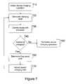
- FIG. 7is a flowchart of a device charging operation.
- FIGS. 8–10are block diagrams of an implantable electronic device.
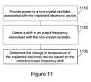
- FIG. 11is a flowchart of a method of determining the change in temperature of an implantable electronic device.
- FIG. 1presents an implantable electronic device, or stimulator 100 , that is configured to provide stimulus to surrounding nerves and tissues once implanted in a patient.
- the stimulator 100can stimulate tissue directly or indirectly to elicit a desired response, which can be inhibitory or excitatory.
- the stimulator 100also can deliver one or more of, e.g., electrical stimuli, chemical stimuli, thermal stimuli, electromagnetic stimuli, and/or mechanical stimuli in order to elicit a desired response in a variety of settings.
- the stimulator 100can stimulate tissue by electrically exciting the depolarization of a nerve and/or muscle tissue.
- the stimulator 100can stimulate tissue by delivering chemical stimuli or electromagnetic stimuli, such as light.
- the stimulator 100can include one or more elements to deliver stimuli to tissue, including, e.g., electrodes, drug delivery elements, heaters, coolers, light sources, fiber optics, and/or mechanical elements such as piezoelectric elements, balloons, Micro-Electro-Mechanical Systems devices, and the like.
- elements to deliver stimuli to tissueincluding, e.g., electrodes, drug delivery elements, heaters, coolers, light sources, fiber optics, and/or mechanical elements such as piezoelectric elements, balloons, Micro-Electro-Mechanical Systems devices, and the like.
- the stimulator 100can comprise an implantable pulse generator (IPG) coupled to a lead of electrodes, a spinal cord stimulator (SCS), a cochlear implant, a deep brain stimulator, a drug pump, a micro-drug pump, microstimulator, or any other type of implantable stimulator configured to deliver electrical and/or chemical stimuli.
- IPGimplantable pulse generator
- SCSspinal cord stimulator
- cochlear implanta cochlear implant
- a deep brain stimulatora drug pump
- micro-drug pumpa micro-drug pump
- microstimulatormicrostimulator
- Example IPG'sinclude those described in U.S. Pat. Nos. 6,381,496, 6,553,263, and 6,760,626, the contents of all of which are incorporated herein by reference.
- Example SCS'sinclude those described in U.S. Pat. Nos. 5,501,703, 6,487,446, and 6,516,227, the contents of all of which are incorporated herein by reference.
- Example cochlear implantsinclude those described in U.S. Pat. Nos. 6,219,580, 6,272,382, and 6,308,101, the contents of ail of which are incorporated herein by reference.
- Example deep brain stimulatorsinclude those described in U.S. Pat. Nos.
- Example drug pumpsinclude those described in U.S. Pat. Nos. 4,562,751, 4,678,408, 4,685,903, 5,080,653, 5,097,122, 6,740,072, and 6,770,067, the contents of all of which are incorporated herein by reference.
- Example micro-drug pumpsinclude those described in U.S. Pat. Nos. 5,234,692, 5,234,693, 5,728,396, 6,368,315, 6,666,845, and 6,620,151, the contents of all of which are incorporated herein by reference.
- the stimulator 100can be enclosed a narrow, elongated housing 110 that includes a programmable memory 120 , electrical circuitry 130 , and a rechargeable power source 140 .
- the electrical circuitry 130is connected to electrodes 150 and 160 , which can deliver electrical stimulation to surrounding tissues and nerves.
- the electrodes 150 and 160can comprise leadless electrodes that pass through the housing 110 .
- the electrodes 150 and 160can be affixed to leads and thus be positioned away from the housing 110 by a distance suitable for the intended application.
- the electrodes 150 and 160generally comprise a stimulating electrode, which is placed in proximity to the nerve or tissue that is to be stimulated, and an indifferent electrode, which completes the circuit and thereby facilitates electrical stimulation.
- the external surfaces of the housing 110can be constructed of one or more biocompatible materials, including glass, ceramic, or other material that provides a hermetic package capable of excluding water vapor and permitting the passage of electromagnetic fields, such as the electromagnetic fields used to transfer power and signals to the stimulator 100 .
- the electrodes 150 and 160can be comprised of a noble or refractory metal or compound, such as platinum, iridium, tantalum, titanium, titanium nitride, niobium, or similar alloys that will resist corrosion or electrolysis that can damage the stimulator 100 or the surrounding tissues and nerves.
- the external surfaces of the housing 110can be constructed of a noble metal or compound, or some combination of a noble metal or compound and one or more biocompatible materials, such as glass or ceramic.
- the programmable memory 120 included in the stimulator 100can be used to store data, such as stimulation parameters and control parameters.
- the data stored in the programmable memory 120can be communicated to, or reprogrammed by, an external device through one-way or bi-directional communication.
- the electrical circuitry 130can be configured to store data in the programmable memory 120 during operation of the stimulator 100 .
- the electrical circuitry 130 included in the stimulator 100can include circuitry for receiving power and/or signals transmitted by an external source.
- the electrical circuitry 130can include an inductive coil for receiving power from an electromagnetic field, and for receiving and/or transmitting data via one or more electromagnetic fields.
- the electrical circuitry 130can include one or more integrated circuits for performing control functions, such as decoding and storing data received from an external source, generating stimulation pulses based on stimulation parameters, and monitoring the state of charge of the rechargeable power source 140 .
- the electrical circuitry 130can further include discrete electronic components used to perform the functions of the stimulator 100 , such as capacitors, resistors, transistors, and demodulators.
- the rechargeable power source 140can be an electrolytic capacitor or a secondary battery, such as a lithium-ion or a lithium-ion polymer battery.
- the electrical circuitry 130also can include circuitry for recharging the rechargeable power source 140 , such as the charging control circuit described below.
- the implantable electronic devicecan comprise a different type of device that is adapted to the requirements of a different application.
- the implantable electronic devicecan comprise a spinal cord stimulator device that is adapted to treat chronic pain.
- the implantable electronic devicecan comprise a pacemaker adapted to treat cardiac arrhythmia.
- the implantable electronic device implementationcan include a type of rechargeable power source and various electrical circuitry for monitoring, controlling, and protecting the rechargeable power source.
- the stimulator 100can comprise a portion of a stimulator system 200 that includes an internal portion 202 and an external portion 204 .
- the internal portion 202lies inside of the body of a patient 210 and is comprised of one or more stimulators, including the stimulator 100 .
- the external portion 204 of the stimulator system 200comprises a control system that is used to communicate with, and provide power to, the one or more stimulators included in the internal portion 202 .
- the patient 210is positioned within the operating range of an external interface 220 when a device charging operation or communication with the stimulator 100 is to be initiated.
- the external interface 220can include one or more inductive coils 230 that are used to generate an electromagnetic field.
- the electromagnetic fieldcan be generated with sufficient strength to penetrate the tissue of the patient 210 beyond the minimum implant depth of the stimulator 100 .
- the stimulator 100can thereby be inductively coupled with the external interface 220 and thus the external controller 240 .
- the external controller 240provides signals and power to the external interface 220 through a cable interface 270 .
- the external interface 220can also provide signals to the external controller 240 through the cable interface 270 .
- the external interface 220 and the external controller 240can communicate through a wireless interface (not shown) instead of, or in addition to, the cable interface 270 .
- the external interface 220further can include an independent power supply, such as a connection to a conventional power source or a battery.
- the external controller 240also can include a connection to a conventional power source 250 , such as an alternating current adapter. Additionally, the external controller 240 can include a control interface 260 that receives input from one or more users, such as a caregiver or a patient. The control interface 260 also can output information relating to the status and the configuration of the stimulator 100 to the one or more users.
- the control interface 260can be any control interface or combination of control interfaces known in the art, including a mouse, a keyboard, a keypad, a touch screen, a touch pad, a voice command interface, an electromechanical switch, a speaker, and a visual display device.
- the external interface 220can be embedded in a fixed location, such as a charging table, a charging chair, or a similar structure.
- the external interface 220can be included in a portable object, such as a charging paddle, a cushion, a pillow, or a similar object.
- the external interface 220can be adapted to be worn by or affixed to the patient 210 .
- the external interface 220can be worn on a belt, inserted into a pouch in a garment, or affixed to the patient using VELCRO® or an adhesive.
- the external interface 220can be inductively coupled to the stimulator 100 through an electromagnetic field 300 generated at the external interface 220 .
- the stimulator 100can be inductively coupled to the external interface 220 , and thus to the external controller 240 , through an electromagnetic field 310 generated by the stimulator 100 .
- the stimulator 100can thereby transmit signals to the external interface 220 and the external controller 240 .
- signalscan be transmitted between the external interface 220 and the stimulator 100 using a single electromagnetic field, such as the electromagnetic field 300 .
- FIG. 4presents a flowchart describing an implementation of the communication process between the external controller 240 and the stimulator 100 .
- the external controller 240can transmit one or more communication request signals through the external interface 220 in a first step 410 .
- the stimulator 100must expend power to monitor for the receipt of a communication request signal. Therefore, the stimulator 100 can be configured to periodically open a listen window for a short duration. For example, the stimulator 100 can be configured to open a 13 millisecond listen window every 1.5 seconds. Because the stimulator 100 does not have a listen window open at all times, the external controller 240 may be required to transmit more than one communication request signal before such signal is successfully received by the stimulator 100 . In a second step 420 , the external controller 240 stops generating the electromagnetic field after transmitting a communication request signal and waits for a predetermined period of time to receive an acknowledgement signal from the stimulator 100 .
- the stimulator 100can wait for a predetermined period of time and then transmit an acknowledgement signal to indicate that the communication request signal has been received.
- the external controller 240determines whether an acknowledgement signal from the stimulator 100 has been received. If no acknowledgement signal has been received, the external controller 240 returns to the first step 410 and transmits one or more additional communication request signals.
- the external controller 240can implement an iterative approach, such as a frequency hopping operation, in order to establish communication with the stimulator 100 .
- the external controller 240can transmit one or more communication request signals at a first frequency that corresponds to a frequency at which the stimulator 100 is expected to communicate. If, after a predetermined period of time, communication cannot be established with the stimulator 100 at the first frequency, the external controller 240 can transmit one or more additional communication request signals at a second frequency. In this manner, the external controller 240 can continue to transmit communication request signals to the stimulator 100 at different frequencies until communication is established.
- the communication frequencycan be stored by the external controller 240 as a starting frequency. The next time the external controller 240 attempts to establish communication with the stimulator 100 , the external controller 240 can select the starting frequency as the frequency at which the initial communication request signals are transmitted.
- the stimulator 100can be configured to use the output frequency of an oscillator included in the electrical circuitry 130 as the center frequency for transmissions.
- the stimulator 100transmits on a center frequency that is approximately 127 kHz using frequency shift keying.
- the stimulator 100represents a digital 0 by transmitting at a frequency f O for a predetermined period, where f O is, for example, 4 kHz less than the center frequency.
- the stimulator 100represents a digital 1 by transmitting at a frequency f 1 for a predetermined period, where f 1 is, for example, 4 kHz greater than the center frequency.
- the stimulator 100can thus transmit an acknowledgement signal using either or both of these frequencies.
- the stimulator 100can transmit an acknowledgement signal comprising an unmodulated signal at frequency f O for a predetermined period of time.
- the stimulator 100can be configured to transmit at one or more different frequencies using a different protocol, such as phase shift keying.
- predetermined messagescan be exchanged in a fourth step 440 .
- the stimulator 100can transmit one or more messages describing the status of the stimulator 100 , including a current voltage of the rechargeable power source 140 , stimulation parameters, and other device settings.
- the external controller 240can transmit additional data and commands to the stimulator 100 .
- the external controller 240can reprogram the stimulator 100 by providing new configuration data, such as one or more stimulation parameters.
- a sixth step 460the stimulator 100 determines whether a predetermined period of time has passed since the last communication was received from the external controller 240 . If a predetermined period of time has elapsed without additional communication from the external controller 240 , the stimulator 100 determines that the communication session has ended and returns to a default state in a seventh step 470 , in which the stimulator 100 periodically opens a listen window for a short period of time. In order to reestablish communications with the stimulator 100 once it has returned to its default state, the external control 240 must once again execute the first step 410 .
- FIG. 5An implementation of a device charging system included in the stimulator system 200 is shown in FIG. 5 .
- the stimulator 100is implanted beneath the skin of the patient 210 .
- the rechargeable power source 140 contained in the stimulator 100must be recharged periodically, so that the stimulator 100 can continue to operate as intended.
- the external controller 240generates a charging field 510 , such as an electromagnetic field, by supplying power to the one or more inductive coils 230 included in the external interface 220 .
- the external controller 240can signal the external interface 220 to generate the charging field 510 and the external interface 220 can draw power from an independent power source, such as an alternating current adapter or battery.
- the external interface 220is placed in proximity to the stimulator 100 that is implanted in the patient 210 . Once the external interface 220 and the stimulator 100 are inductively coupled through the charging field 510 , an alternating current appears across the inductive coil 520 included in the stimulator 100 . The alternating current appearing across the inductive coil 520 can be converted to direct current by an alternating-current to direct-current converter 530 . The direct-current is then used to charge the rechargeable power source 140 , which in turn provides power to the electrical circuitry 130 (not shown) in the stimulator 100 .
- the stimulator 100also can include a charging control circuit 540 that delivers a constant charging current to the rechargeable power source 140 .
- the charging control circuit 540can include circuitry to ensure that the rechargeable power source 140 is charged at the proper rate and is not overcharged, such a field effect transistor switch. Further, the charging control circuit 540 can include a fuse to ensure that the rechargeable power source 140 is not charged with too much current and to protect the rechargeable power source 140 in the event of a short circuit.
- the charging control circuit 540detects that the rechargeable power source 140 has reached the target voltage level, the charging control circuit 540 maintains the rechargeable power source 140 at a constant voltage and directs any additional charging current to a charging protection circuit 550 .
- the charging control circuit 540directs the additional current to the charging protection circuit 550 .
- the charging protection circuit 550is primarily designed to serve as a resistive circuit that dissipates excess current as heat. Therefore, if the external controller 240 generates a charging field 510 that is too strong, or if the strength of the charging field 510 increases due to a change in the alignment of the stimulator 100 and the external interface 220 , the temperature of the stimulator 100 can increase significantly. As such, it is difficult to optimize the strength of the charging field 510 unless the temperature of the stimulator 100 can be determined during the device charging operation.
- the housing 110 of the stimulator 100can be comprised, in whole or in part, of a noble metal or alloy.
- the housing 110can be subject to eddy currents that can contribute to the increase in temperature of a stimulator during communication or device charging operations.
- the electrical circuitry 130 of the stimulator 100also can include a non-crystal oscillator, such as a ring-oscillator or a resistor-capacitor oscillator.
- FIG. 6presents an implementation of a ring-oscillator 600 that can be used to provide an output frequency signal f out to the stimulator 100 .
- Various configurations of the ring-oscillator 600can be implemented using discrete circuit elements included in the electrical circuitry 130 of the stimulator 100 .
- the ring-oscillator 600includes an enable line 610 and a feedback line 620 that serve as inputs to the AND gate 630 .
- the ring-oscillator 600also includes an odd number of inverters 640 , which cause the oscillation. The signal output from the inverters 640 is directed back to the AND gate 630 on the feedback line 620 and is provided as an output frequency signal f out on the output line 650 .
- the stimulator 100can include a crystal oscillator that provides an output frequency signal to the stimulator 100 during normal operation and a non-crystal oscillator, such as the ring-oscillator 600 , that provides an output frequency signal to the stimulator 100 during at least a portion of the device charging operation.
- the ring-oscillator 600can be disabled during normal operation.
- the crystal oscillatorcan be disabled and the ring-oscillator 600 can be enabled by providing an enable signal to the AND gate 630 on the enable line 610 .
- the enable signalcan be provided to the AND gate 630 for a predetermined period of time. Alternatively, the enable signal can be provided to the AND gate 630 until the external controller 240 commands the stimulator 100 to disable the ring-oscillator 600 .
- a non-crystal oscillatorsuch as the ring-oscillator 600 , is used to provide the output frequency signal f out during device charging operations because non-crystal oscillators are subject to frequency shift under a number of circumstances.
- determining the frequency shift associated with a non-crystal oscillatorit is possible to determine the change in the temperature of an implanted electronic device during a device charging operation. For example, an increase in the rechargeable power source voltage is known to produce a frequency shift of approximately 0.8% per volt, which equates to approximately 1 kHz per volt in a system with a center frequency of 127 kHz.
- a change in the temperature of a deviceis known to produce a frequency shift of approximately 0.1% per degree Celsius, which equates to approximately 127 Hz per degree Celsius.
- an increase in the age of an integrated circuitis known to produce a frequency shift of approximately 1.0% per year.
- the present voltage of the rechargeable power source 140can be determined during a device charging operation, it is also possible to factor out the frequency shift produced as a result of the rechargeable power source voltage from the total detected frequency shift.
- the remaining frequency shiftcan be attributed to the change in the temperature of the stimulator 100 during the device charging operation. It has been experimentally determined that approximately 370–380 Hz of frequency shift resulting from a change in the temperature corresponds to a change in the temperature of approximately 3 degrees Celsius. As such, the frequency shift attributable to a change in the temperature can be measured periodically during a device charging operation to ensure that the temperature of stimulator 100 remains within an acceptable range.
- FIG. 7presents a flowchart describing a device charging operation during which frequency shift is considered.
- the external controller 240initiates a device charging operation by establishing communication with the stimulator 100 .
- the frequencies at which the stimulator 100 communicatesmay change. Therefore, the external controller 240 can implement an iterative process, such as a frequency hopping operation, in order to establish communication with the stimulator 100 .
- the communication frequencycan be stored as a starting frequency by the external controller 240 .
- the external controller 240can select the starting frequency as the frequency at which one or more initial communication request signals are transmitted.
- the external controller 240can be calibrated before establishing communication with the stimulator 100 . For example, if the external controller 240 expects to receive signals from the stimulator 100 at specific frequencies, such as f 0 equal to 123 kHz and f, equal to 131 kHz, a receiver in the external controller 240 can be tuned to those frequencies.
- the stimulator 100transmits an acknowledgement signal as part of the communication process, wherein the acknowledgement signal can be based on the center frequency f out output from the non-crystal oscillator included in the stimulator 100 , such as the ring-oscillator 600 .
- the stimulator 100can transmit an unmodulated acknowledgement signal at the frequency f O for a period of 6 milliseconds.
- the external controller 240can detect the frequency of the acknowledgement signal, such as by measuring the pulse-width, determining the time interval between successive rising edges, or counting the number of pulses received within a specific time period. The external controller can then convert the detected frequency to a voltage measure representing the initial frequency of the stimulator 100 and store the initial voltage measure. In another implementation, the external controller 240 can store the detected frequency as a frequency value.
- the stimulator 100can transmit one or more parameters to the external controller 240 for use during the device charging operation, such as an initial voltage of the rechargeable power source 140 and configuration information.
- the external controller 240also can transmit commands and information to the stimulator 100 , such as reprogramming information.
- the external controller 240generates a charging field through the external interface 220 in a second step 720 .
- the charging fieldis maintained for a predetermined charging interval, which can be selected with respect to efficiency and patient safety. For example, a two minute charging interval can be selected where the charging field strength is such that the maximum temperature increase of the device undergoing charging over that interval is 3 degrees Celsius.
- the external controller 240can then reestablish communication with the stimulator 100 at the end of the charging interval in a third step 730 .
- the stimulator 100transmits an acknowledgement signal as part of the communication process.
- the external controller 240can once again detect the frequency of the acknowledgement signal, convert the detected frequency to a voltage measure representing the present frequency of the stimulator 100 , and store the present voltage measure.
- the frequency of the acknowledgement signalcan be stored as a frequency value.
- the stimulator 100also transmits parameters describing the status of the stimulator 100 to the external controller 240 , including the present voltage of the rechargeable power source 140 and the present voltage of a charging node included in the stimulator 100 .
- the external controller 240uses the present voltage of the rechargeable power source 140 to determine whether additional charging is required in a fourth step 740 . If the rechargeable power source 140 has reached the target voltage, the device charging operation is terminated in a fifth step 750 .
- the external controller 240compares the present voltage measure with the initial voltage measure to determine the change in voltage in a sixth step 760 .
- the change in voltageis then resolved and converted to Hz to determine the total frequency shift that has occurred during the device charging operation.
- the present voltage of the rechargeable power source 140is used to determine the frequency shift attributable to the rechargeable power source 140 voltage, which is then factored out of the total frequency shift.
- the frequency shift due to circuit agingalso can be determined and factored out of the total frequency shift.
- the external controller 240determines the change in the temperature of the stimulator 100 based on the adjusted frequency shift.
- the acknowledgement signal frequenciesare stored as frequency values
- the total frequency shift that has occurred during the device charging operationcan be determined by comparing the frequencies directly.
- the charging field generated by the external controller 240can be adjusted in response to determined change in temperature in a seventh step 770 .
- the safety threshold for a particular stimulatormay correspond to an adjusted frequency shift of 370–380 Hz. If the adjusted frequency shift is approaching or exceeding the safety threshold, the external controller 240 can suspend additional charging for a predetermined period of time or until the adjusted frequency shift decreases to a safer level. If the adjusted frequency shift falls within a moderate range, the external controller 240 can examine the present voltage of the charging node to determine the field strength received by the stimulator 100 during the previous charging interval.
- the external controller 240can determine whether the amount of power being supplied to the one or more inductive coils 230 in the external interface 220 should be decreased during the subsequent charging interval. Similarly, if the adjusted frequency shift falls within a low range, the external controller 240 can determine the field strength received by the stimulator 100 during the previous charging interval. Based on the field strength received by the stimulator 100 , the external controller 240 can determine whether the amount of power being supplied to the one or more inductive coils 230 in the external interface 220 should be increased during the subsequent charging interval. Once the external controller 240 has adjusted the charging parameters, the device charging operation returns to the second step 720 and a new charging field is generated.
- FIGS. 8 , 9 , and 10present another implementation of the internal portion 202 of the stimulator system 200 .
- FIG. 8shows a side view of a stimulator 800
- FIG. 9shows a sectional view of the stimulator 800 along the line 801 — 801 in FIG. 8
- FIG. 10shows an end view of the stimulator 800 .
- the stimulator 800includes a pair of electrodes 802 and 804 , a power source 902 , an electronic subassembly 904 , and a case 1002 .
- the button electrode 802is an active/stimulating electrode whereas electrode 804 is an indifferent/reference electrode.
- the pair of electrodes 802 and 804can be made from any of the materials discussed above.
- the power source 902provides power for the delivery of electrical stimuli to tissue through the pair of electrodes 802 and 804 .
- the power source 902can be a rechargeable power source, such as a rechargeable battery, a capacitor, or the like.
- the power source 902can be a lithium-ion battery or other suitable type of battery that can be recharged through the use of a charging field 510 ( FIG. 5 ) or other form of power transfer.
- a charging field 510FIG. 5
- One type of rechargeable battery that can be usedis disclosed in International Publication WO 01/82398 A1, published 1 Nov. 2001, and/or WO 03/005465 A1, published 16 Jan. 2003, the contents of both of which are incorporated herein by reference.
- the electronic subassembly 904includes a coil 906 and a stimulating capacitor 908 .
- the button electrode 802is coupled to the electronic subassembly 904 through the stimulating capacitor 908 .
- the coil 906can receive power for charging the power source 902 using power received from the charging field 510 ( FIG. 5 ).
- the electronic subassembly 904also can comprise circuitry for stimulation, telemetry, production testing, behavioral control, and battery charging, including a non-crystal oscillator.
- the stimulation circuitrycan be further divided into components for high voltage generation, stimulation phase current control, recovery phase current control, charge balance control, and over voltage protection circuitry.
- the telemetry circuitrycan be further divided into an on-off keying (OOK) receiver, a frequency shift keying (FSK) receiver, and an FSK transmitter.
- OOKon-off keying
- FSKfrequency shift keying
- the behavioral control circuitrycan be further divided into components for stimulation timing, high voltage generation closed loop control, telemetry packet handling, and battery management.
- charging circuitry within the electronic subassembly 904can detect the presence of an external charging field, such as the charging field 510 ( FIG. 5 ). Upon detection, the stimulator 800 can receive a telemetry message and recharge the power source 902 , as necessary. As described above, the electronic subassembly 904 can measure a voltage during recharging and transmit the measured voltage value to an external device, such as the external interface 220 ( FIG. 2 ). Battery voltage measurements can be made at times when stimulation pulses are not being delivered.
- U.S. Pat. No. 6,553,263, incorporated herein by referencedescribes charging technology that also can be used.
- the electronic subassembly 904can use the charge stored on the capacitor to power the stimulator 800 during times of peak power demand. Such times include times when telemetry signals are being transmitted from the stimulator 800 to one or more external device(s), or when the amplitude of the stimulation pulses has been programmed to be relatively high.
- the electronic subassembly 904can use the charge stored on the capacitor to recharge the rechargeable battery or to power the stimulator 800 at times of high power demand.
- the electronic subassembly 904also can include protection circuitry to act as a failsafe against battery over-voltage.
- a battery protection circuitcan continuously monitor a battery's voltage and electrically disconnect the battery if its voltage exceeds a preset value.
- the electronic subassembly 904can include a memory and a processor and/or other electronic circuitry that allow it to generate stimulating pulses that are applied to a patient through the pair of electrodes 802 and 804 in accordance with logic located within the electronic subassembly 904 .
- the processor and/or other electronic circuitryalso can control data communication with an external device, such as the external interface 220 ( FIG. 2 ).
- the processor and/or other electronic circuitrycan allow the stimulator 800 to perform processes described above.
- the electronic subassembly 904also can include a panel 910 , integrated circuitry 912 , capacitors 914 , diodes 916 , and two ferrite halves 918 .
- the arrangement of these components in electronic subassembly 904is described in U.S. Patent Publication No. 2005/0021108, the contents of which is incorporated herein by reference.
- the stimulator 800can have a case 1002 characterized by a tubular or cylindrical shape with an outer diameter greater than about 3.20 mm and less than about 3.70 mm.
- the case 1002can have an outer diameter of about 3.30 mm.
- the case 1002can have an inner diameter that encloses the electronic subassembly 904 and is greater than about 2.40 mm and less than about 2.54 mm.
- the case 1002also can have an inner diameter that encloses the power source 902 and is greater than about 2.92 mm and less than about 3.05 mm.
- the length of the case 1002can be less than about 30.00 mm, and greater than about 27.00 mm.
- the portion of the case 1002 that encloses the electronic subassembly 904can be less than about 13.00 mm in length and the portion of the case 1002 that encloses the power source 902 can be about 11.84 mm in length. These dimensions are only examples and can be changed to accommodate different types of power sources.
- the stimulator 800can have a rectangular or ovoid cross section instead of being cylindrically shaped.
- the case 1002can be Magnetic Resonance Imaging (MRI) compatible.
- MRIMagnetic Resonance Imaging
- the case 1002can be sealed to protect the electrical components contained within the stimulator 800 .
- the case 1002can be hermetically-sealed and made from two cylindrical cases, namely, a titanium 6/4 case 920 and a zirconia ceramic case 812 .
- Other materials and shapes for the case 1002also can be used.
- a titanium 6/4 or other suitable connector 924can be brazed with a titanium nickel alloy (or other suitable material) to ceramic case 812 for securing the mating end of titanium case 920 .
- a connector 924has an inside flange 924 A and an outside flange 924 B which serve to “self center” the braze assembly.
- conductive silicone adhesive 926can be applied to the inside end of the ceramic shell as well as to the inside end of the titanium shell.
- a molecular sieve moisture getter material 928is also added to areas 928 A, 928 B, and 928 C ( FIG. 9 ) before the brazing process.
- the “spiral” self centering button electrode 802can be made from titanium 6/4 or other suitable material and plated with an iridium coating or other suitable conductive coating.
- An end view of the button electrode 802is shown in FIG. 10 .
- a spiral groove 936can be made in stimulating surface 934 of the button electrode 802 .
- Other groove shapes, such as a cross hatch pattern or other patternscan also be used to increase the area of the stimulating surface 934 of the button electrode 802 .
- the sharp edges in groove 936can force a more homogeneous current distribution over the stimulating surface 934 and decrease the likelihood of electrode corrosion over time by reducing current density along the sharp groove edges.
- a tool made in the shape of a trapezoid or similar shapecan be used to cut the groove 936 into a spiral or other shape.
- Other devices for cutting the groove 936can be used such as, e.g., ion beam etching.
- the button electrode 802can act as active or stimulating electrode.
- a titanium/nickel alloy 930 or other suitable materialcan be used to braze the button electrode 802 to the zirconia ceramic case 812 .
- An end view of the stimulator 800is shown in FIG. 10 , where the end view of the stimulating “spiral” button electrode 802 can be seen.
- the end 932 of the titanium shell 920can be plated with an iridium coating (other suitable conductive coating can be applied), which plated area becomes the indifferent iridium electrode 804 .
- FIG. 8shows a top view of the stimulator 800 with the external coatings depicted.
- a type C parylene or other suitable electrically insulating coatingcan be applied to the shaded area 806 , e.g., by standard masking and vapor deposition processes.
- the zirconia ceramic case 812is left exposed in area 808 and the iridium electrode 804 is shown on the end 810 of the titanium case 920 .
- U.S. Pat. No. 6,582,441incorporated herein by reference, describes a surgical insertion tool which can be used for implanting the stimulator 800 .
- the procedures taught in the '441 patent for using the tool and associated componentscan be used for implanting and extracting the stimulator 800 .
- the surgical insertion tool described in the '441 patentfacilitates the implantation of the stimulator 800 in a patient so that the button electrode 802 is proximate to a nerve site (e.g., near the pudendal nerve for treating patients with urinary urge incontinence).
- the distance between the button electrode 802 and the nerve sitecan be, for example, less than 1–2 mm.
- the stimulator 800also can be implanted in other nerve sites relating to preventing and/or treating various disorders associated with, e.g., prolonged inactivity, confinement, or immobilization of one or more muscles and/or as therapy for various purposes including paralyzed muscles and limbs, by providing stimulation of one or more cavernous nerves for an effective therapy for erectile or other sexual dysfunctions, and/or by treating other disorders, e.g., neurological disorders caused by injury or stroke.
- FIG. 11describes a method of determining a change in temperature of an implanted electronic device.
- a first step 1110power is provided to a non-crystal oscillator associated with the implanted electronic device.
- a shift in an output frequency associated with the non-crystal oscillatoris detected.
- the third step 1130is to determine the change in temperature of the implanted electronic device based on the detected output frequency shift.
Landscapes
- Physics & Mathematics (AREA)
- General Physics & Mathematics (AREA)
- Chemical & Material Sciences (AREA)
- Crystallography & Structural Chemistry (AREA)
- Electrotherapy Devices (AREA)
Abstract
Description
Claims (11)
Priority Applications (2)
| Application Number | Priority Date | Filing Date | Title |
|---|---|---|---|
| US11/130,644US7200504B1 (en) | 2005-05-16 | 2005-05-16 | Measuring temperature change in an electronic biomedical implant |
| US11/676,202US7426445B1 (en) | 2005-05-16 | 2007-02-16 | Measuring temperature change in an electronic biomedical implant |
Applications Claiming Priority (1)
| Application Number | Priority Date | Filing Date | Title |
|---|---|---|---|
| US11/130,644US7200504B1 (en) | 2005-05-16 | 2005-05-16 | Measuring temperature change in an electronic biomedical implant |
Related Child Applications (1)
| Application Number | Title | Priority Date | Filing Date |
|---|---|---|---|
| US11/676,202ContinuationUS7426445B1 (en) | 2005-05-16 | 2007-02-16 | Measuring temperature change in an electronic biomedical implant |
Publications (1)
| Publication Number | Publication Date |
|---|---|
| US7200504B1true US7200504B1 (en) | 2007-04-03 |
Family
ID=37897674
Family Applications (2)
| Application Number | Title | Priority Date | Filing Date |
|---|---|---|---|
| US11/130,644Expired - Fee RelatedUS7200504B1 (en) | 2005-05-16 | 2005-05-16 | Measuring temperature change in an electronic biomedical implant |
| US11/676,202Expired - Fee RelatedUS7426445B1 (en) | 2005-05-16 | 2007-02-16 | Measuring temperature change in an electronic biomedical implant |
Family Applications After (1)
| Application Number | Title | Priority Date | Filing Date |
|---|---|---|---|
| US11/676,202Expired - Fee RelatedUS7426445B1 (en) | 2005-05-16 | 2007-02-16 | Measuring temperature change in an electronic biomedical implant |
Country Status (1)
| Country | Link |
|---|---|
| US (2) | US7200504B1 (en) |
Cited By (51)
| Publication number | Priority date | Publication date | Assignee | Title |
|---|---|---|---|---|
| US20050137651A1 (en)* | 2003-11-21 | 2005-06-23 | Litvak Leonid M. | Optimizing pitch allocation in a cochlear implant |
| US20060264897A1 (en)* | 2005-01-24 | 2006-11-23 | Neurosystec Corporation | Apparatus and method for delivering therapeutic and/or other agents to the inner ear and to other tissues |
| US20070055308A1 (en)* | 2005-09-06 | 2007-03-08 | Haller Matthew I | Ultracapacitor powered implantable pulse generator with dedicated power supply |
| US20070123938A1 (en)* | 2005-11-30 | 2007-05-31 | Haller Matthew I | Magnetically coupled microstimulators |
| US20070255237A1 (en)* | 2006-05-01 | 2007-11-01 | Neurosystec Corporation | Apparatus and method for delivery of therapeutic and other types of agents |
| US20080243212A1 (en)* | 2007-03-29 | 2008-10-02 | Cardiac Pacemakers, Inc. | Systems and methods for thermal neuroinhibition |
| US7450994B1 (en) | 2004-12-16 | 2008-11-11 | Advanced Bionics, Llc | Estimating flap thickness for cochlear implants |
| US20090118796A1 (en)* | 2007-11-05 | 2009-05-07 | Advanced Bionics Corporation | External controller for an implantable medical device system with coupleable external charging coil assembly |
| WO2009055866A1 (en)* | 2007-10-31 | 2009-05-07 | Cochlear Limited | Implantable medical prothesis system capable of detecting symptoms of medical conditions |
| WO2009055865A1 (en)* | 2007-10-31 | 2009-05-07 | Cochlear Limited | Implantable prosthesis with sensor |
| US20090187237A1 (en)* | 2004-11-17 | 2009-07-23 | Advanced Bionics, Llc | Inner Hair Cell Stimulation Model for Use by a Cochlear Implant System |
| US20090222064A1 (en)* | 2005-07-08 | 2009-09-03 | Advanced Bionics, Llc | Autonomous Autoprogram Cochlear Implant |
| US7599500B1 (en) | 2004-12-09 | 2009-10-06 | Advanced Bionics, Llc | Processing signals representative of sound based on the identity of an input element |
| US20090287278A1 (en)* | 2008-05-15 | 2009-11-19 | Neurelec | Implantable subcutaneous device |
| US7729775B1 (en) | 2006-03-21 | 2010-06-01 | Advanced Bionics, Llc | Spectral contrast enhancement in a cochlear implant speech processor |
| US20100204756A1 (en)* | 2009-02-10 | 2010-08-12 | Boston Scientific Neuromodulation Corporation | External Device for Communicating with an Implantable Medical Device Having Data Telemetry and Charging Integrated in a Single Housing |
| US7783362B2 (en) | 2002-06-20 | 2010-08-24 | Boston Scientific Neuromodulation Corporation | Vagus nerve stimulation via unidirectional propagation of action potentials |
| US7803148B2 (en) | 2006-06-09 | 2010-09-28 | Neurosystec Corporation | Flow-induced delivery from a drug mass |
| US20100292759A1 (en)* | 2005-03-24 | 2010-11-18 | Hahn Tae W | Magnetic field sensor for magnetically-coupled medical implant devices |
| US20100331913A1 (en)* | 2005-10-28 | 2010-12-30 | Mann Alfred E | Hybrid multi-function electrode array |
| US20110069853A1 (en)* | 2006-09-25 | 2011-03-24 | Advanced Bionics, Llc | Auditory Front End Customization |
| US20110087307A1 (en)* | 2009-10-08 | 2011-04-14 | Boston Scientific Neuromodulation Corporation | Efficient External Charger for an Implantable Medical Device Optimized for Fast Charging and Constrained by an Implant Power Dissipation Limit |
| US7995771B1 (en) | 2006-09-25 | 2011-08-09 | Advanced Bionics, Llc | Beamforming microphone system |
| US8027733B1 (en) | 2005-10-28 | 2011-09-27 | Advanced Bionics, Llc | Optimizing pitch allocation in a cochlear stimulation system |
| US20120112750A1 (en)* | 2010-05-11 | 2012-05-10 | Stefan Assmann | Apparatus with local coil arrangement and implantable device |
| US8321029B2 (en) | 2009-09-18 | 2012-11-27 | Boston Scientific Neuromodulation Corporation | External charger usable with an implantable medical device having a programmable or time-varying temperature set point |
| US8548604B2 (en) | 2002-06-20 | 2013-10-01 | Boston Scientific Neuromodulation Corporation | Implantable microstimulators and methods for unidirectional propagation of action potentials |
| US8594806B2 (en) | 2010-04-30 | 2013-11-26 | Cyberonics, Inc. | Recharging and communication lead for an implantable device |
| US8676318B2 (en) | 2009-11-23 | 2014-03-18 | Boston Scientific Neuromodulation Corporation | Efficient external charger for charging a plurality of implantable medical devices |
| US8682444B2 (en) | 2011-12-21 | 2014-03-25 | Boston Scientific Neuromodulation Corporation | System for an implantable medical device having an external charger coupleable to accessory charging coils |
| US8712547B2 (en) | 2002-06-20 | 2014-04-29 | Boston Scientific Neuromodulation Corporation | Cavernous nerve stimulation via unidirectional propagation of action potentials |
| US8818517B2 (en) | 2006-05-05 | 2014-08-26 | Advanced Bionics Ag | Information processing and storage in a cochlear stimulation system |
| US8886333B2 (en) | 2012-07-19 | 2014-11-11 | Boston Scientific Neuromodulation Corporation | Self-affixing external charging system for an implantable medical device |
| US9343923B2 (en) | 2012-08-23 | 2016-05-17 | Cyberonics, Inc. | Implantable medical device with backscatter signal based communication |
| US9393421B2 (en) | 2005-05-26 | 2016-07-19 | Boston Scientific Neuromodulation Corporation | Controlling charge flow in the electrical stimulation of tissue |
| US9409028B2 (en) | 2002-06-20 | 2016-08-09 | Boston Scientific Neuromodulation Corporation | Implantable microstimulators with programmable multielectrode configuration and uses thereof |
| US9929584B2 (en) | 2014-10-30 | 2018-03-27 | Boston Scientific Neuromodulation Corporation | External charging coil assembly for charging a medical device |
| US9935498B2 (en) | 2012-09-25 | 2018-04-03 | Cyberonics, Inc. | Communication efficiency with an implantable medical device using a circulator and a backscatter signal |
| US10058702B2 (en) | 2003-04-09 | 2018-08-28 | Cochlear Limited | Implant magnet system |
| US10105545B2 (en) | 2015-03-12 | 2018-10-23 | Boston Scientific Neuromodulation Corporation | Assembly with a coaxial audio connector for charging an implantable medical device |
| US10130807B2 (en) | 2015-06-12 | 2018-11-20 | Cochlear Limited | Magnet management MRI compatibility |
| WO2019199952A1 (en)* | 2018-04-10 | 2019-10-17 | Tandem Diabetes Care, Inc. | System and method for inductively charging a medical device |
| US10576276B2 (en) | 2016-04-29 | 2020-03-03 | Cochlear Limited | Implanted magnet management in the face of external magnetic fields |
| US10848882B2 (en) | 2007-05-24 | 2020-11-24 | Cochlear Limited | Implant abutment |
| US10917730B2 (en) | 2015-09-14 | 2021-02-09 | Cochlear Limited | Retention magnet system for medical device |
| US11018654B1 (en)* | 2019-06-11 | 2021-05-25 | Marvell Asia Pte, Ltd. | Temperature sensor with reduced power supply voltage sensitivity |
| US11452171B2 (en)* | 2019-10-28 | 2022-09-20 | Kabushiki Kaisha Toshiba | Electronic apparatus and method |
| US11595768B2 (en) | 2016-12-02 | 2023-02-28 | Cochlear Limited | Retention force increasing components |
| US11792587B1 (en) | 2015-06-26 | 2023-10-17 | Cochlear Limited | Magnetic retention device |
| US12003925B2 (en) | 2014-07-29 | 2024-06-04 | Cochlear Limited | Magnetic retention system |
| US12420101B2 (en) | 2019-09-27 | 2025-09-23 | Cochlear Limited | Multipole magnet for medical implant system |
Families Citing this family (3)
| Publication number | Priority date | Publication date | Assignee | Title |
|---|---|---|---|---|
| US7242985B1 (en)* | 2004-12-03 | 2007-07-10 | Advanced Bionics Corporation | Outer hair cell stimulation model for the use by an intra—cochlear implant |
| US7706892B2 (en)* | 2005-01-20 | 2010-04-27 | Boston Scientific Neuromodulation Corporation | Implantable microstimulator with plastic housing and methods of manufacture and use |
| CN107029349A (en) | 2012-03-09 | 2017-08-11 | 安特罗麦迪克斯公司 | Safety feature in Medical Devices |
Citations (58)
| Publication number | Priority date | Publication date | Assignee | Title |
|---|---|---|---|---|
| US4481950A (en)* | 1979-04-27 | 1984-11-13 | Medtronic, Inc. | Acoustic signalling apparatus for implantable devices |
| US4562751A (en) | 1984-01-06 | 1986-01-07 | Nason Clyde K | Solenoid drive apparatus for an external infusion pump |
| US4678408A (en) | 1984-01-06 | 1987-07-07 | Pacesetter Infusion, Ltd. | Solenoid drive apparatus for an external infusion pump |
| US4685903A (en) | 1984-01-06 | 1987-08-11 | Pacesetter Infusion, Ltd. | External infusion pump apparatus |
| US5080653A (en) | 1990-04-16 | 1992-01-14 | Pacesetter Infusion, Ltd. | Infusion pump with dual position syringe locator |
| US5097122A (en) | 1990-04-16 | 1992-03-17 | Pacesetter Infusion, Ltd. | Medication infusion system having optical motion sensor to detect drive mechanism malfunction |
| US5193539A (en) | 1991-12-18 | 1993-03-16 | Alfred E. Mann Foundation For Scientific Research | Implantable microstimulator |
| US5193540A (en) | 1991-12-18 | 1993-03-16 | Alfred E. Mann Foundation For Scientific Research | Structure and method of manufacture of an implantable microstimulator |
| US5234693A (en) | 1990-07-11 | 1993-08-10 | Alza Corporation | Delivery device with a protective sleeve |
| US5234692A (en) | 1990-07-11 | 1993-08-10 | Alza Corporation | Delivery device with a protective sleeve |
| US5312439A (en) | 1991-12-12 | 1994-05-17 | Loeb Gerald E | Implantable device having an electrolytic storage electrode |
| US5314458A (en)* | 1990-06-01 | 1994-05-24 | University Of Michigan | Single channel microstimulator |
| US5501703A (en) | 1994-01-24 | 1996-03-26 | Medtronic, Inc. | Multichannel apparatus for epidural spinal cord stimulator |
| US5728396A (en) | 1996-02-02 | 1998-03-17 | Alza Corporation | Sustained delivery of leuprolide using an implantable system |
| US5938688A (en) | 1997-10-22 | 1999-08-17 | Cornell Research Foundation, Inc. | Deep brain stimulation method |
| US6016449A (en) | 1997-10-27 | 2000-01-18 | Neuropace, Inc. | System for treatment of neurological disorders |
| US6051017A (en) | 1996-02-20 | 2000-04-18 | Advanced Bionics Corporation | Implantable microstimulator and systems employing the same |
| US6164284A (en) | 1997-02-26 | 2000-12-26 | Schulman; Joseph H. | System of implantable devices for monitoring and/or affecting body parameters |
| US6185452B1 (en) | 1997-02-26 | 2001-02-06 | Joseph H. Schulman | Battery-powered patient implantable device |
| US6208894B1 (en) | 1997-02-26 | 2001-03-27 | Alfred E. Mann Foundation For Scientific Research And Advanced Bionics | System of implantable devices for monitoring and/or affecting body parameters |
| US6219580B1 (en) | 1995-04-26 | 2001-04-17 | Advanced Bionics Corporation | Multichannel cochlear prosthesis with flexible control of stimulus waveforms |
| US6272382B1 (en) | 1998-07-31 | 2001-08-07 | Advanced Bionics Corporation | Fully implantable cochlear implant system |
| US6280873B1 (en) | 1999-04-08 | 2001-08-28 | Quallion, Llc | Wound battery and method for making it |
| US6308101B1 (en) | 1998-07-31 | 2001-10-23 | Advanced Bionics Corporation | Fully implantable cochlear implant system |
| WO2001082398A1 (en) | 2000-04-26 | 2001-11-01 | Quallion, Llc | Lithium ion battery capable of being discharged to zero volts |
| US20010046625A1 (en) | 2000-02-02 | 2001-11-29 | Ruth Douglas Alan | Brazed ceramic seal for batteries with titanium-titanium-6A1-4V cases |
| US20010053476A1 (en) | 2000-04-26 | 2001-12-20 | Alan Ruth | Lithium ion battery suitable for hybrid electric vehicles |
| US6368315B1 (en) | 1999-06-23 | 2002-04-09 | Durect Corporation | Composite drug delivery catheter |
| US6381496B1 (en) | 1999-10-01 | 2002-04-30 | Advanced Bionics Corporation | Parameter context switching for an implanted device |
| US6458171B1 (en) | 1999-04-16 | 2002-10-01 | Quallion Llc | Battery tab attachment method |
| US6487446B1 (en) | 2000-09-26 | 2002-11-26 | Medtronic, Inc. | Method and system for spinal cord stimulation prior to and during a medical procedure |
| WO2003005465A1 (en) | 2001-04-25 | 2003-01-16 | Quallion, Llc | Rechargeable lithium battery for tolerating discharge to zero volts |
| US6516227B1 (en) | 1999-07-27 | 2003-02-04 | Advanced Bionics Corporation | Rechargeable spinal cord stimulator system |
| US6539263B1 (en) | 1999-06-11 | 2003-03-25 | Cornell Research Foundation, Inc. | Feedback mechanism for deep brain stimulation |
| US6553263B1 (en) | 1999-07-30 | 2003-04-22 | Advanced Bionics Corporation | Implantable pulse generators using rechargeable zero-volt technology lithium-ion batteries |
| US6582441B1 (en) | 2000-02-24 | 2003-06-24 | Advanced Bionics Corporation | Surgical insertion tool |
| US6620151B2 (en) | 2001-03-01 | 2003-09-16 | Advanced Neuromodulation Systems, Inc. | Non-constant pressure infusion pump |
| US20030229383A1 (en) | 2002-06-11 | 2003-12-11 | Whitehurst Todd K. | RF telemetry link for establishment and maintenance of communications with an implantable device |
| US6666845B2 (en) | 2001-01-04 | 2003-12-23 | Advanced Neuromodulation Systems, Inc. | Implantable infusion pump |
| US20030236558A1 (en) | 2002-06-20 | 2003-12-25 | Whitehurst Todd K. | Vagus nerve stimulation via unidirectional propagation of action potentials |
| US20030236557A1 (en) | 2002-06-20 | 2003-12-25 | Whitehurst Todd K. | Cavernous nerve stimulation via unidirectional propagation of action potentials |
| US20040015204A1 (en) | 2002-06-20 | 2004-01-22 | Whitehurst Todd K. | Implantable microstimulators and methods for unidirectional propagation of action potentials |
| US20040015205A1 (en) | 2002-06-20 | 2004-01-22 | Whitehurst Todd K. | Implantable microstimulators with programmable multielectrode configuration and uses thereof |
| US20040044383A1 (en) | 2002-08-30 | 2004-03-04 | Woods Carla Mann | Status indicator for implantable systems |
| US20040059392A1 (en) | 2002-06-28 | 2004-03-25 | Jordi Parramon | Microstimulator having self-contained power source |
| US6740072B2 (en) | 2001-09-07 | 2004-05-25 | Medtronic Minimed, Inc. | System and method for providing closed loop infusion formulation delivery |
| US6760626B1 (en) | 2001-08-29 | 2004-07-06 | Birinder R. Boveja | Apparatus and method for treatment of neurological and neuropsychiatric disorders using programmerless implantable pulse generator system |
| US6770067B2 (en) | 2001-09-07 | 2004-08-03 | Medtronic Minimed, Inc. | Infusion device and driving mechanism for same |
| US20040162590A1 (en) | 2002-12-19 | 2004-08-19 | Whitehurst Todd K. | Fully implantable miniature neurostimulator for intercostal nerve stimulation as a therapy for angina pectoris |
| US20040230231A1 (en) | 2002-11-15 | 2004-11-18 | Thacker James R. | Method and system for treating atrial fibrillation |
| US6856838B2 (en) | 2000-03-17 | 2005-02-15 | Advanced Bionics Corporation | Voltage converter for implantable microstimulator using RF-powering coil |
| US20050102006A1 (en) | 2003-09-25 | 2005-05-12 | Whitehurst Todd K. | Skull-mounted electrical stimulation system |
| US20050119176A1 (en) | 2001-11-21 | 2005-06-02 | The Burnham Institute | Methods and compositions for derepression of IAP-inhibited caspase |
| US20050131494A1 (en) | 2002-06-28 | 2005-06-16 | Park Rudolph V. | Systems and methods for communicating with an implantable stimulator |
| US20050131495A1 (en) | 2002-06-28 | 2005-06-16 | Jordi Parramon | Systems and methods for providing power to a battery in an implantable stimulator |
| US20050143781A1 (en) | 2003-01-31 | 2005-06-30 | Rafael Carbunaru | Methods and systems for patient adjustment of parameters for an implanted stimulator |
| US20050154419A1 (en) | 2001-01-30 | 2005-07-14 | Whitehurst Todd K. | Methods and systems for stimulating a nerve originating in an upper cervical spine area to treat a medical condition |
| US20050245971A1 (en)* | 2004-04-28 | 2005-11-03 | Brockway Brian P | Implantable medical devices and related methods |
Family Cites Families (2)
| Publication number | Priority date | Publication date | Assignee | Title |
|---|---|---|---|---|
| US5704352A (en)* | 1995-11-22 | 1998-01-06 | Tremblay; Gerald F. | Implantable passive bio-sensor |
| WO2002022205A1 (en)* | 2000-09-13 | 2002-03-21 | Alfred E. Mann Institute For Biomedical Engineering At The University Of Southern California | Method and apparatus for conditioning muscles during sleep |
- 2005
- 2005-05-16USUS11/130,644patent/US7200504B1/ennot_activeExpired - Fee Related
- 2007
- 2007-02-16USUS11/676,202patent/US7426445B1/ennot_activeExpired - Fee Related
Patent Citations (63)
| Publication number | Priority date | Publication date | Assignee | Title |
|---|---|---|---|---|
| US4481950A (en)* | 1979-04-27 | 1984-11-13 | Medtronic, Inc. | Acoustic signalling apparatus for implantable devices |
| US4562751A (en) | 1984-01-06 | 1986-01-07 | Nason Clyde K | Solenoid drive apparatus for an external infusion pump |
| US4678408A (en) | 1984-01-06 | 1987-07-07 | Pacesetter Infusion, Ltd. | Solenoid drive apparatus for an external infusion pump |
| US4685903A (en) | 1984-01-06 | 1987-08-11 | Pacesetter Infusion, Ltd. | External infusion pump apparatus |
| US5080653A (en) | 1990-04-16 | 1992-01-14 | Pacesetter Infusion, Ltd. | Infusion pump with dual position syringe locator |
| US5097122A (en) | 1990-04-16 | 1992-03-17 | Pacesetter Infusion, Ltd. | Medication infusion system having optical motion sensor to detect drive mechanism malfunction |
| US5314458A (en)* | 1990-06-01 | 1994-05-24 | University Of Michigan | Single channel microstimulator |
| US5234693A (en) | 1990-07-11 | 1993-08-10 | Alza Corporation | Delivery device with a protective sleeve |
| US5234692A (en) | 1990-07-11 | 1993-08-10 | Alza Corporation | Delivery device with a protective sleeve |
| US5312439A (en) | 1991-12-12 | 1994-05-17 | Loeb Gerald E | Implantable device having an electrolytic storage electrode |
| US5193540A (en) | 1991-12-18 | 1993-03-16 | Alfred E. Mann Foundation For Scientific Research | Structure and method of manufacture of an implantable microstimulator |
| US5193539A (en) | 1991-12-18 | 1993-03-16 | Alfred E. Mann Foundation For Scientific Research | Implantable microstimulator |
| US5501703A (en) | 1994-01-24 | 1996-03-26 | Medtronic, Inc. | Multichannel apparatus for epidural spinal cord stimulator |
| US6219580B1 (en) | 1995-04-26 | 2001-04-17 | Advanced Bionics Corporation | Multichannel cochlear prosthesis with flexible control of stimulus waveforms |
| US5728396A (en) | 1996-02-02 | 1998-03-17 | Alza Corporation | Sustained delivery of leuprolide using an implantable system |
| US6051017A (en) | 1996-02-20 | 2000-04-18 | Advanced Bionics Corporation | Implantable microstimulator and systems employing the same |
| US6185452B1 (en) | 1997-02-26 | 2001-02-06 | Joseph H. Schulman | Battery-powered patient implantable device |
| US6164284A (en) | 1997-02-26 | 2000-12-26 | Schulman; Joseph H. | System of implantable devices for monitoring and/or affecting body parameters |
| US6208894B1 (en) | 1997-02-26 | 2001-03-27 | Alfred E. Mann Foundation For Scientific Research And Advanced Bionics | System of implantable devices for monitoring and/or affecting body parameters |
| US5938688A (en) | 1997-10-22 | 1999-08-17 | Cornell Research Foundation, Inc. | Deep brain stimulation method |
| US6016449A (en) | 1997-10-27 | 2000-01-18 | Neuropace, Inc. | System for treatment of neurological disorders |
| US6272382B1 (en) | 1998-07-31 | 2001-08-07 | Advanced Bionics Corporation | Fully implantable cochlear implant system |
| US6308101B1 (en) | 1998-07-31 | 2001-10-23 | Advanced Bionics Corporation | Fully implantable cochlear implant system |
| US6280873B1 (en) | 1999-04-08 | 2001-08-28 | Quallion, Llc | Wound battery and method for making it |
| US6458171B1 (en) | 1999-04-16 | 2002-10-01 | Quallion Llc | Battery tab attachment method |
| US6539263B1 (en) | 1999-06-11 | 2003-03-25 | Cornell Research Foundation, Inc. | Feedback mechanism for deep brain stimulation |
| US6368315B1 (en) | 1999-06-23 | 2002-04-09 | Durect Corporation | Composite drug delivery catheter |
| US6516227B1 (en) | 1999-07-27 | 2003-02-04 | Advanced Bionics Corporation | Rechargeable spinal cord stimulator system |
| US6553263B1 (en) | 1999-07-30 | 2003-04-22 | Advanced Bionics Corporation | Implantable pulse generators using rechargeable zero-volt technology lithium-ion batteries |
| US6381496B1 (en) | 1999-10-01 | 2002-04-30 | Advanced Bionics Corporation | Parameter context switching for an implanted device |
| US20010046625A1 (en) | 2000-02-02 | 2001-11-29 | Ruth Douglas Alan | Brazed ceramic seal for batteries with titanium-titanium-6A1-4V cases |
| US6582441B1 (en) | 2000-02-24 | 2003-06-24 | Advanced Bionics Corporation | Surgical insertion tool |
| US6856838B2 (en) | 2000-03-17 | 2005-02-15 | Advanced Bionics Corporation | Voltage converter for implantable microstimulator using RF-powering coil |
| US20050131496A1 (en) | 2000-03-17 | 2005-06-16 | Jordi Parramon | Voltage converter for implantable microstimulator using RF-powering coil |
| US20010053476A1 (en) | 2000-04-26 | 2001-12-20 | Alan Ruth | Lithium ion battery suitable for hybrid electric vehicles |
| WO2001082398A1 (en) | 2000-04-26 | 2001-11-01 | Quallion, Llc | Lithium ion battery capable of being discharged to zero volts |
| US6487446B1 (en) | 2000-09-26 | 2002-11-26 | Medtronic, Inc. | Method and system for spinal cord stimulation prior to and during a medical procedure |
| US6666845B2 (en) | 2001-01-04 | 2003-12-23 | Advanced Neuromodulation Systems, Inc. | Implantable infusion pump |
| US20050154419A1 (en) | 2001-01-30 | 2005-07-14 | Whitehurst Todd K. | Methods and systems for stimulating a nerve originating in an upper cervical spine area to treat a medical condition |
| US6620151B2 (en) | 2001-03-01 | 2003-09-16 | Advanced Neuromodulation Systems, Inc. | Non-constant pressure infusion pump |
| WO2003005465A1 (en) | 2001-04-25 | 2003-01-16 | Quallion, Llc | Rechargeable lithium battery for tolerating discharge to zero volts |
| US6760626B1 (en) | 2001-08-29 | 2004-07-06 | Birinder R. Boveja | Apparatus and method for treatment of neurological and neuropsychiatric disorders using programmerless implantable pulse generator system |
| US6740072B2 (en) | 2001-09-07 | 2004-05-25 | Medtronic Minimed, Inc. | System and method for providing closed loop infusion formulation delivery |
| US6770067B2 (en) | 2001-09-07 | 2004-08-03 | Medtronic Minimed, Inc. | Infusion device and driving mechanism for same |
| US20050119176A1 (en) | 2001-11-21 | 2005-06-02 | The Burnham Institute | Methods and compositions for derepression of IAP-inhibited caspase |
| US20030229383A1 (en) | 2002-06-11 | 2003-12-11 | Whitehurst Todd K. | RF telemetry link for establishment and maintenance of communications with an implantable device |
| US20040015205A1 (en) | 2002-06-20 | 2004-01-22 | Whitehurst Todd K. | Implantable microstimulators with programmable multielectrode configuration and uses thereof |
| US20040015204A1 (en) | 2002-06-20 | 2004-01-22 | Whitehurst Todd K. | Implantable microstimulators and methods for unidirectional propagation of action potentials |
| US20030236557A1 (en) | 2002-06-20 | 2003-12-25 | Whitehurst Todd K. | Cavernous nerve stimulation via unidirectional propagation of action potentials |
| US20030236558A1 (en) | 2002-06-20 | 2003-12-25 | Whitehurst Todd K. | Vagus nerve stimulation via unidirectional propagation of action potentials |
| US20040098068A1 (en) | 2002-06-28 | 2004-05-20 | Rafael Carbunaru | Chair pad charging and communication system for a battery-powered microstimulator |
| US20040088032A1 (en) | 2002-06-28 | 2004-05-06 | Haller Matthew I. | Electrode assembly for a microstimulator |
| US20040059392A1 (en) | 2002-06-28 | 2004-03-25 | Jordi Parramon | Microstimulator having self-contained power source |
| US20050131494A1 (en) | 2002-06-28 | 2005-06-16 | Park Rudolph V. | Systems and methods for communicating with an implantable stimulator |
| US20050131495A1 (en) | 2002-06-28 | 2005-06-16 | Jordi Parramon | Systems and methods for providing power to a battery in an implantable stimulator |
| US20050021108A1 (en) | 2002-06-28 | 2005-01-27 | Klosterman Daniel J. | Bi-directional telemetry system for use with microstimulator |
| US20050057905A1 (en) | 2002-06-28 | 2005-03-17 | He Tom Xiaohai | Electronic module design to maximize the volume efficiency in a miniature medical device |
| US20040044383A1 (en) | 2002-08-30 | 2004-03-04 | Woods Carla Mann | Status indicator for implantable systems |
| US20040230231A1 (en) | 2002-11-15 | 2004-11-18 | Thacker James R. | Method and system for treating atrial fibrillation |
| US20040162590A1 (en) | 2002-12-19 | 2004-08-19 | Whitehurst Todd K. | Fully implantable miniature neurostimulator for intercostal nerve stimulation as a therapy for angina pectoris |
| US20050143781A1 (en) | 2003-01-31 | 2005-06-30 | Rafael Carbunaru | Methods and systems for patient adjustment of parameters for an implanted stimulator |
| US20050102006A1 (en) | 2003-09-25 | 2005-05-12 | Whitehurst Todd K. | Skull-mounted electrical stimulation system |
| US20050245971A1 (en)* | 2004-04-28 | 2005-11-03 | Brockway Brian P | Implantable medical devices and related methods |
Cited By (98)
| Publication number | Priority date | Publication date | Assignee | Title |
|---|---|---|---|---|
| US8712547B2 (en) | 2002-06-20 | 2014-04-29 | Boston Scientific Neuromodulation Corporation | Cavernous nerve stimulation via unidirectional propagation of action potentials |
| US9409028B2 (en) | 2002-06-20 | 2016-08-09 | Boston Scientific Neuromodulation Corporation | Implantable microstimulators with programmable multielectrode configuration and uses thereof |
| US8548604B2 (en) | 2002-06-20 | 2013-10-01 | Boston Scientific Neuromodulation Corporation | Implantable microstimulators and methods for unidirectional propagation of action potentials |
| US7783362B2 (en) | 2002-06-20 | 2010-08-24 | Boston Scientific Neuromodulation Corporation | Vagus nerve stimulation via unidirectional propagation of action potentials |
| US9283394B2 (en) | 2002-06-20 | 2016-03-15 | Boston Scientific Neuromodulation Corporation | Implantable microstimulators and methods for unidirectional propagation of action potentials |
| US11090498B2 (en) | 2003-04-09 | 2021-08-17 | Cochlear Limited | Implant magnet system |
| US10232171B2 (en) | 2003-04-09 | 2019-03-19 | Cochlear Limited | Implant magnet system |
| US10058702B2 (en) | 2003-04-09 | 2018-08-28 | Cochlear Limited | Implant magnet system |
| US11135440B2 (en) | 2003-04-09 | 2021-10-05 | Cochlear Limited | Implant magnet system |
| US20050137651A1 (en)* | 2003-11-21 | 2005-06-23 | Litvak Leonid M. | Optimizing pitch allocation in a cochlear implant |
| US8620445B2 (en) | 2003-11-21 | 2013-12-31 | Advanced Bionics Ag | Optimizing pitch allocation in a cochlear implant |
| US8180455B2 (en) | 2003-11-21 | 2012-05-15 | Advanced Bionics, LLV | Optimizing pitch allocation in a cochlear implant |
| US7702396B2 (en) | 2003-11-21 | 2010-04-20 | Advanced Bionics, Llc | Optimizing pitch allocation in a cochlear implant |
| US20100121412A1 (en)* | 2003-11-21 | 2010-05-13 | Advanced Bionics, Llc | Optimizing Pitch Allocation in a Cochlear Implant |
| US9254384B2 (en) | 2004-11-17 | 2016-02-09 | Advanced Bionics Ag | Inner hair cell stimulation model for use by a cochlear implant system |
| US20090187237A1 (en)* | 2004-11-17 | 2009-07-23 | Advanced Bionics, Llc | Inner Hair Cell Stimulation Model for Use by a Cochlear Implant System |
| US8615302B2 (en) | 2004-11-17 | 2013-12-24 | Advanced Bionics Ag | Inner hair cell stimulation model for use by a cochlear implant system |
| US9393414B2 (en) | 2004-11-17 | 2016-07-19 | Advanced Bionics Ag | Inner hair cell stimulation model for use by a cochlear implant system |
| US8265286B2 (en) | 2004-12-09 | 2012-09-11 | Advanced Bionics Corporation | Processing signals representative of sound based on the identity of an input element |
| US7599500B1 (en) | 2004-12-09 | 2009-10-06 | Advanced Bionics, Llc | Processing signals representative of sound based on the identity of an input element |
| US7920924B2 (en) | 2004-12-16 | 2011-04-05 | Advanced Bionics, Llc | Estimating flap thickness for cochlear implants |
| US20090030485A1 (en)* | 2004-12-16 | 2009-01-29 | Advanced Bionics, Llc | Estimating Flap Thickness For Cochlear Implants |
| US7450994B1 (en) | 2004-12-16 | 2008-11-11 | Advanced Bionics, Llc | Estimating flap thickness for cochlear implants |
| US20060264897A1 (en)* | 2005-01-24 | 2006-11-23 | Neurosystec Corporation | Apparatus and method for delivering therapeutic and/or other agents to the inner ear and to other tissues |
| US20100292759A1 (en)* | 2005-03-24 | 2010-11-18 | Hahn Tae W | Magnetic field sensor for magnetically-coupled medical implant devices |
| US9393421B2 (en) | 2005-05-26 | 2016-07-19 | Boston Scientific Neuromodulation Corporation | Controlling charge flow in the electrical stimulation of tissue |
| US11179568B2 (en) | 2005-05-26 | 2021-11-23 | Boston Scientific Neuromodufation Corporation | Controlling charge flow in the electrical stimulation of tissue |
| US10065039B2 (en) | 2005-05-26 | 2018-09-04 | Boston Scientific Neuromodulation Corporation | Controlling charge flow in the electrical stimulation of tissue |
| US20090222064A1 (en)* | 2005-07-08 | 2009-09-03 | Advanced Bionics, Llc | Autonomous Autoprogram Cochlear Implant |
| US20070055308A1 (en)* | 2005-09-06 | 2007-03-08 | Haller Matthew I | Ultracapacitor powered implantable pulse generator with dedicated power supply |
| US8175717B2 (en) | 2005-09-06 | 2012-05-08 | Boston Scientific Neuromodulation Corporation | Ultracapacitor powered implantable pulse generator with dedicated power supply |
| US8027733B1 (en) | 2005-10-28 | 2011-09-27 | Advanced Bionics, Llc | Optimizing pitch allocation in a cochlear stimulation system |
| US20100331913A1 (en)* | 2005-10-28 | 2010-12-30 | Mann Alfred E | Hybrid multi-function electrode array |
| US8295937B2 (en) | 2005-10-28 | 2012-10-23 | Advanced Bionics, Llc | Optimizing pitch allocation in a cochlear stimulation system |
| US20070123938A1 (en)* | 2005-11-30 | 2007-05-31 | Haller Matthew I | Magnetically coupled microstimulators |
| US7729758B2 (en) | 2005-11-30 | 2010-06-01 | Boston Scientific Neuromodulation Corporation | Magnetically coupled microstimulators |
| US7729775B1 (en) | 2006-03-21 | 2010-06-01 | Advanced Bionics, Llc | Spectral contrast enhancement in a cochlear implant speech processor |
| US8170679B2 (en) | 2006-03-21 | 2012-05-01 | Advanced Bionics, Llc | Spectral contrast enhancement in a cochlear implant speech processor |
| US20070255237A1 (en)* | 2006-05-01 | 2007-11-01 | Neurosystec Corporation | Apparatus and method for delivery of therapeutic and other types of agents |
| US8267905B2 (en) | 2006-05-01 | 2012-09-18 | Neurosystec Corporation | Apparatus and method for delivery of therapeutic and other types of agents |
| US9855425B2 (en) | 2006-05-05 | 2018-01-02 | Advanced Bionics Ag | Information processing and storage in a cochlear stimulation system |
| US8818517B2 (en) | 2006-05-05 | 2014-08-26 | Advanced Bionics Ag | Information processing and storage in a cochlear stimulation system |
| US8298176B2 (en) | 2006-06-09 | 2012-10-30 | Neurosystec Corporation | Flow-induced delivery from a drug mass |
| US7803148B2 (en) | 2006-06-09 | 2010-09-28 | Neurosystec Corporation | Flow-induced delivery from a drug mass |
| US20110069853A1 (en)* | 2006-09-25 | 2011-03-24 | Advanced Bionics, Llc | Auditory Front End Customization |
| US8503685B2 (en) | 2006-09-25 | 2013-08-06 | Advanced Bionics Ag | Auditory front end customization |
| US7995771B1 (en) | 2006-09-25 | 2011-08-09 | Advanced Bionics, Llc | Beamforming microphone system |
| US9668068B2 (en) | 2006-09-25 | 2017-05-30 | Advanced Bionics, Llc | Beamforming microphone system |
| US20080243212A1 (en)* | 2007-03-29 | 2008-10-02 | Cardiac Pacemakers, Inc. | Systems and methods for thermal neuroinhibition |
| US8734499B2 (en)* | 2007-03-29 | 2014-05-27 | Cardiac Pacemakers, Inc. | Systems and methods for thermal neuroinhibition |
| US10848882B2 (en) | 2007-05-24 | 2020-11-24 | Cochlear Limited | Implant abutment |
| WO2009055866A1 (en)* | 2007-10-31 | 2009-05-07 | Cochlear Limited | Implantable medical prothesis system capable of detecting symptoms of medical conditions |
| WO2009055865A1 (en)* | 2007-10-31 | 2009-05-07 | Cochlear Limited | Implantable prosthesis with sensor |
| US8498716B2 (en) | 2007-11-05 | 2013-07-30 | Boston Scientific Neuromodulation Corporation | External controller for an implantable medical device system with coupleable external charging coil assembly |
| US20090118796A1 (en)* | 2007-11-05 | 2009-05-07 | Advanced Bionics Corporation | External controller for an implantable medical device system with coupleable external charging coil assembly |
| US20090287278A1 (en)* | 2008-05-15 | 2009-11-19 | Neurelec | Implantable subcutaneous device |
| US8768480B2 (en) | 2008-05-15 | 2014-07-01 | Neurelec | Implantable subcutaneous device |
| EP2119474A3 (en)* | 2008-05-15 | 2010-03-03 | Neurelec | Subcutaneously implantable device |
| US9020602B2 (en) | 2009-02-10 | 2015-04-28 | Boston Scientific Neuromodulation Corporation | External device for communicating with an implantable medical device having data telemetry and charging integrated in a single housing |
| US8335569B2 (en) | 2009-02-10 | 2012-12-18 | Boston Scientific Neuromodulation Corporation | External device for communicating with an implantable medical device having data telemetry and charging integrated in a single housing |
| US20100204756A1 (en)* | 2009-02-10 | 2010-08-12 | Boston Scientific Neuromodulation Corporation | External Device for Communicating with an Implantable Medical Device Having Data Telemetry and Charging Integrated in a Single Housing |
| US8792990B2 (en) | 2009-09-18 | 2014-07-29 | Boston Scientific Neuromodulation Corporation | External charger usable with an implantable medical device having a programmable or time-varying temperature set point |
| US8571680B2 (en) | 2009-09-18 | 2013-10-29 | Boston Scientific Neuromodulation Corporation | External charger usable with an implantable medical device having a programmable or time-varying temperature set point |
| US8321029B2 (en) | 2009-09-18 | 2012-11-27 | Boston Scientific Neuromodulation Corporation | External charger usable with an implantable medical device having a programmable or time-varying temperature set point |
| US8744592B2 (en) | 2009-10-08 | 2014-06-03 | Boston Scientific Neuromodulation Corporation | Efficient external charger for an implantable medical device optimized for fast charging and constrained by an implant power dissipation limit |
| US9867995B2 (en) | 2009-10-08 | 2018-01-16 | Boston Scientific Neuromodulation Corporation | Efficient external charger for an implantable medical device optimized for fast charging and constrained by an implant power dissipation limit |
| US9358399B2 (en) | 2009-10-08 | 2016-06-07 | Boston Scientific Neuromodulation Corporation | Efficient external charger for an implantable medical device optimized for fast charging and constrained by an implant power dissipation limit |
| US20110087307A1 (en)* | 2009-10-08 | 2011-04-14 | Boston Scientific Neuromodulation Corporation | Efficient External Charger for an Implantable Medical Device Optimized for Fast Charging and Constrained by an Implant Power Dissipation Limit |
| US8676318B2 (en) | 2009-11-23 | 2014-03-18 | Boston Scientific Neuromodulation Corporation | Efficient external charger for charging a plurality of implantable medical devices |
| US9339659B2 (en) | 2009-11-23 | 2016-05-17 | Boston Scientific Neuromodulation Corporation | Efficient external charger for charging a plurality of implantable medical devices |
| US8594806B2 (en) | 2010-04-30 | 2013-11-26 | Cyberonics, Inc. | Recharging and communication lead for an implantable device |
| US8841908B2 (en)* | 2010-05-11 | 2014-09-23 | Siemens Aktiengesellschaft | Apparatus with local coil arrangement and implantable device |
| US20120112750A1 (en)* | 2010-05-11 | 2012-05-10 | Stefan Assmann | Apparatus with local coil arrangement and implantable device |
| US9026220B2 (en) | 2011-12-21 | 2015-05-05 | Boston Scientific Neuromodulation Corporation | System for an implantable medical device having an external charger coupleable to accessory charging coils |
| US8682444B2 (en) | 2011-12-21 | 2014-03-25 | Boston Scientific Neuromodulation Corporation | System for an implantable medical device having an external charger coupleable to accessory charging coils |
| US9407110B2 (en) | 2012-07-19 | 2016-08-02 | Boston Scientific Neuromodulation Corporation | Self-affixing external charging system for an implantable medical device |
| US8886333B2 (en) | 2012-07-19 | 2014-11-11 | Boston Scientific Neuromodulation Corporation | Self-affixing external charging system for an implantable medical device |
| US9343923B2 (en) | 2012-08-23 | 2016-05-17 | Cyberonics, Inc. | Implantable medical device with backscatter signal based communication |
| US9935498B2 (en) | 2012-09-25 | 2018-04-03 | Cyberonics, Inc. | Communication efficiency with an implantable medical device using a circulator and a backscatter signal |
| US12003925B2 (en) | 2014-07-29 | 2024-06-04 | Cochlear Limited | Magnetic retention system |
| US9929584B2 (en) | 2014-10-30 | 2018-03-27 | Boston Scientific Neuromodulation Corporation | External charging coil assembly for charging a medical device |
| US10530179B2 (en) | 2014-10-30 | 2020-01-07 | Boston Scientific Neuromodulation Corporation | External controller for an implantable medical device system with an external charging coil powered by an external battery |
| US10105545B2 (en) | 2015-03-12 | 2018-10-23 | Boston Scientific Neuromodulation Corporation | Assembly with a coaxial audio connector for charging an implantable medical device |
| US11918808B2 (en) | 2015-06-12 | 2024-03-05 | Cochlear Limited | Magnet management MRI compatibility |
| US12383739B2 (en) | 2015-06-12 | 2025-08-12 | Cochlear Limited | Magnet management MRI compatibility |
| US10130807B2 (en) | 2015-06-12 | 2018-11-20 | Cochlear Limited | Magnet management MRI compatibility |
| US11792587B1 (en) | 2015-06-26 | 2023-10-17 | Cochlear Limited | Magnetic retention device |
| US11792586B2 (en) | 2015-09-14 | 2023-10-17 | Cochlear Limited | Retention magnet system for medical device |
| US10917730B2 (en) | 2015-09-14 | 2021-02-09 | Cochlear Limited | Retention magnet system for medical device |
| US12137326B2 (en) | 2015-09-14 | 2024-11-05 | Cochlear Limited | Retention magnet system for medical device |
| US10576276B2 (en) | 2016-04-29 | 2020-03-03 | Cochlear Limited | Implanted magnet management in the face of external magnetic fields |
| US11595768B2 (en) | 2016-12-02 | 2023-02-28 | Cochlear Limited | Retention force increasing components |
| EP3776801A4 (en)* | 2018-04-10 | 2021-12-22 | Tandem Diabetes Care, Inc. | SYSTEM AND METHOD FOR INDUCTIVE CHARGING A MEDICAL DEVICE |
| US11872368B2 (en) | 2018-04-10 | 2024-01-16 | Tandem Diabetes Care, Inc. | System and method for inductively charging a medical device |
| WO2019199952A1 (en)* | 2018-04-10 | 2019-10-17 | Tandem Diabetes Care, Inc. | System and method for inductively charging a medical device |
| US11018654B1 (en)* | 2019-06-11 | 2021-05-25 | Marvell Asia Pte, Ltd. | Temperature sensor with reduced power supply voltage sensitivity |
| US12420101B2 (en) | 2019-09-27 | 2025-09-23 | Cochlear Limited | Multipole magnet for medical implant system |
| US11452171B2 (en)* | 2019-10-28 | 2022-09-20 | Kabushiki Kaisha Toshiba | Electronic apparatus and method |
Also Published As
| Publication number | Publication date |
|---|---|
| US7426445B1 (en) | 2008-09-16 |
Similar Documents
| Publication | Publication Date | Title |
|---|---|---|
| US7200504B1 (en) | Measuring temperature change in an electronic biomedical implant | |
| US11179568B2 (en) | Controlling charge flow in the electrical stimulation of tissue | |
| US7729758B2 (en) | Magnetically coupled microstimulators | |
| US7801602B2 (en) | Controlling stimulation parameters of implanted tissue stimulators | |
| US7813809B2 (en) | Implantable pulse generator for providing functional and/or therapeutic stimulation of muscles and/or nerves and/or central nervous system tissue | |
| US9867995B2 (en) | Efficient external charger for an implantable medical device optimized for fast charging and constrained by an implant power dissipation limit | |
| EP1922112B1 (en) | Ultracapacitor powered implantable pulse generator with dedicated power supply for the volatile memory | |
| US10010717B2 (en) | External charger with adjustable alignment indicator | |
| EP2806946B1 (en) | Managing recharge power for implantable medical devices | |
| US8428746B2 (en) | Moldable charger with shape-sensing means for an implantable pulse generator | |
| EP2148724B1 (en) | Smart charger alignment indicator | |
| US20100010582A1 (en) | Medical system and method for setting programmable heat limits | |
| US20070293910A1 (en) | Implantable pulse generator for providing functional and/or therapeutic stimulation of muscles and/or nerves and/or central nervous system tissue | |
| EP2662114A1 (en) | An efficient external charger for charging a plurality of implantable medical devices | |
| US20070299483A1 (en) | Implantable pulse generator for providing functional and/or therapeutic stimulation of muscles and/or nerves and/or central nervous system tissue | |
| JP2009519771A (en) | Techniques for sensing and adjusting the compliance voltage of implantable stimulators | |
| JP2013542836A (en) | Notification of start status of implantable nerve stimulator |
Legal Events
| Date | Code | Title | Description |
|---|---|---|---|
| FEPP | Fee payment procedure | Free format text:PAYOR NUMBER ASSIGNED (ORIGINAL EVENT CODE: ASPN); ENTITY STATUS OF PATENT OWNER: LARGE ENTITY | |
| AS | Assignment | Owner name:ADVANCED BIONICS CORPORATION, CALIFORNIA Free format text:ASSIGNMENT OF ASSIGNORS INTEREST;ASSIGNOR:FISTER, MICHAEL L.;REEL/FRAME:018779/0725 Effective date:20050511 | |
| STCF | Information on status: patent grant | Free format text:PATENTED CASE | |
| AS | Assignment | Owner name:BOSTON SCIENTIFIC NEUROMODULATION CORPORATION, CAL Free format text:CHANGE OF NAME;ASSIGNOR:ADVANCED BIONICS CORPORATION;REEL/FRAME:020299/0200 Effective date:20071116 | |
| AS | Assignment | Owner name:BOSTON SCIENTIFIC NEUROMODULATION CORPORATION, CAL Free format text:CHANGE OF NAME;ASSIGNOR:ADVANCED BIONICS CORPORATION;REEL/FRAME:020309/0361 Effective date:20071116 | |
| FPAY | Fee payment | Year of fee payment:4 | |
| FPAY | Fee payment | Year of fee payment:8 | |
| FEPP | Fee payment procedure | Free format text:MAINTENANCE FEE REMINDER MAILED (ORIGINAL EVENT CODE: REM.); ENTITY STATUS OF PATENT OWNER: LARGE ENTITY | |
| LAPS | Lapse for failure to pay maintenance fees | Free format text:PATENT EXPIRED FOR FAILURE TO PAY MAINTENANCE FEES (ORIGINAL EVENT CODE: EXP.); ENTITY STATUS OF PATENT OWNER: LARGE ENTITY | |
| STCH | Information on status: patent discontinuation | Free format text:PATENT EXPIRED DUE TO NONPAYMENT OF MAINTENANCE FEES UNDER 37 CFR 1.362 | |
| FP | Lapsed due to failure to pay maintenance fee | Effective date:20190403 |