US7200314B2 - Carrier for multiple splice trays - Google Patents
Carrier for multiple splice traysDownload PDFInfo
- Publication number
- US7200314B2 US7200314B2US10/840,681US84068104AUS7200314B2US 7200314 B2US7200314 B2US 7200314B2US 84068104 AUS84068104 AUS 84068104AUS 7200314 B2US7200314 B2US 7200314B2
- Authority
- US
- United States
- Prior art keywords
- carrier
- splice
- access position
- splice site
- carrier members
- Prior art date
- Legal status (The legal status is an assumption and is not a legal conclusion. Google has not performed a legal analysis and makes no representation as to the accuracy of the status listed.)
- Expired - Fee Related, expires
Links
Images


Classifications
- G—PHYSICS
- G02—OPTICS
- G02B—OPTICAL ELEMENTS, SYSTEMS OR APPARATUS
- G02B6/00—Light guides; Structural details of arrangements comprising light guides and other optical elements, e.g. couplings
- G02B6/44—Mechanical structures for providing tensile strength and external protection for fibres, e.g. optical transmission cables
- G02B6/4439—Auxiliary devices
- G02B6/444—Systems or boxes with surplus lengths
- G02B6/4452—Distribution frames
- G02B6/44524—Distribution frames with frame parts or auxiliary devices mounted on the frame and collectively not covering a whole width of the frame or rack
- G—PHYSICS
- G02—OPTICS
- G02B—OPTICAL ELEMENTS, SYSTEMS OR APPARATUS
- G02B6/00—Light guides; Structural details of arrangements comprising light guides and other optical elements, e.g. couplings
- G02B6/44—Mechanical structures for providing tensile strength and external protection for fibres, e.g. optical transmission cables
- G02B6/4439—Auxiliary devices
- G02B6/444—Systems or boxes with surplus lengths
- G02B6/4453—Cassettes
- G02B6/4455—Cassettes characterised by the way of extraction or insertion of the cassette in the distribution frame, e.g. pivoting, sliding, rotating or gliding
Definitions
- the present inventionis directed to the splicing of optical fibers, and more particularly to the splicing of optical fibers with splicing trays.
- Optical fibers and cableshave become very common data carriers.
- One issue that can arise with optical fibersis their interconnection with other optical fibers.
- many industrial, office and apartment buildingsinclude data centers, where cables transmitting data from outside the building are ultimately interconnected with devices (phones, computers, and the like) inside the building.
- devicesphones, computers, and the like
- incoming optical fiberspass to the data center in cable form, where they are spliced together with “pigtail” cables.
- the pigtail cablestravel to a termination point, where they are interconnected with a termination device (for example, a termination cartridge or module) that, in turn, interconnects them with “jumper” fibers that exit to other parts of the building for use with various devices.
- a termination devicefor example, a termination cartridge or module
- Splicing of optical fibersis often accomplished via one of three different splicing techniques: mechanical splicing; fusion splicing; or mass fusion splicing. These techniques are well known and need not be described in detail herein.
- Splicesare often stored in splice trays, which are generally planar devices that include multiple splicing sites designed to organize interconnected fibers and splices. Splice trays can assist in keeping a number of spliced fibers in an organized arrangement (typically a tray will have a capacity of 6 to 24 splices). Splice trays are then stored inside shelves on an equipment rack within the data center.
- An exemplary splice trayis the 2524-MF FIBRLOK multi-fiber splice organizer tray, available from 3M, Minneapolis, Minn.
- a splice site carrier of the present inventionincludes an interconnecting member and a plurality of generally planar carrier members that are pivotally interconnected with the interconnecting member.
- the carrier membersare configured to receive a splice tray mounted on a front side thereof.
- Each of the carrier membersis pivotable about a respective pivot axis between an access position, in which the front side of the carrier member faces in a first direction, such that the splice tray is presented for access to splice sites thereon, and a non-access position that is at least partially inverted from the access position, in which a rear side of the carrier member is presented and the splice tray is not accessible.
- an access positionin which the front side of the carrier member faces in a first direction, such that the splice tray is presented for access to splice sites thereon
- a non-access positionthat is at least partially inverted from the access position, in which a rear side of the carrier member is presented and the splice tray is not accessible.
- the interconnecting memberis a base, with the carrier members being pivotally interconnected with the base.
- the respective pivot axes of the carrier membersmay be staggered vertically and horizontally relative to one another.
- the non-access positionmay cause the front side of the carrier member to be generally inverted from the access position, or may cause the front side of the carrier member to face in a direction generally normal to that of the access position.
- the splice site carriercan be formed of an elongate sheet of flexible material that is folded upon itself to form a plurality of leaves that serve as carrier members, with intermediate panels positioned between pairs of leaves serving as the interconnecting member.
- the carrier memberspivot relative to the intermediate panels via living hinges formed in the elongate sheet.
- a cover memberthat is also formed from the flexible sheet can be employed to secure the carrier members in their access positions.
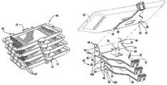
- FIG. 1is a perspective view of a splice site carrier according to embodiments of the present invention, wherein the carrier members are shown in their access positions.
- FIG. 2is a side view of the splice site carrier of FIG. 1 with the carrier members in their access positions
- FIG. 2Ais a side view of the splice site carrier of FIG. 1 as shown in FIG. 2 , with the frontmost carrier member in its non-access position.
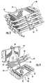
- FIG. 3is a top perspective view of a splice site carrier according to other embodiments of the present invention, wherein the carrier members are shown in their access positions.
- FIG. 4is a top perspective view of the splice site carrier of FIG. 3 with one carrier member shown in its non-access position and two carrier members shown in an intermediate position.
- FIG. 5is a partially exploded top perspective view of the splice site carrier of FIG. 3 with three splice trays removed and one splice tray shown in phantom line.
- FIG. 6is a bottom perspective view of the splice site carrier of FIG. 3 with the carrier members in their access positions.
- FIG. 7is a bottom perspective view of an alternative embodiment of a splice site carrier like that in FIGS. 3–6 configured for floor mounting.
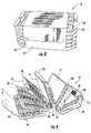
- FIG. 8is a perspective view of a splice site carrier according to additional embodiments of the present invention, wherein the carrier panels are secured in their access positions by the cover member.
- FIG. 9is a side perspective view of the splice site carrier of FIG. 8 with the cover member detached and the carrier panels and splice trays mounted thereto in a variety of intermediate positions.
- FIG. 10Ais a top view of a blank of an elongate flexible sheet used to form the splice site carrier of FIG. 8 .
- FIG. 10Bis a bottom view of a blank of an elongate flexible sheet used to form the splice site carrier of FIG. 8 .
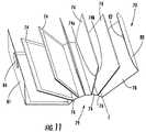
- FIG. 11is a side perspective view of the splice site carrier of FIG. 9 with the splice trays removed.
- FIG. 12is a perspective view of a splice site carrier of FIGS. 9–11 in place in a data center shelf.
- the carrier 20includes a base 22 configured to rest on or be mounted upon an underlying surface, such as the upper surface of a shelf within a data center equipment rack.
- the base 22has a floor 23 and short side rails 24 on opposite sides of the floor 23 .
- Four slotted apertures 26 with open upper endsare located on each side rail 24 .
- the apertures 26are positioned such that each aperture 26 is in substantial alignment with an aperture 26 on the opposite side rail 24 , with the result that each opposing pair of apertures 26 forms a respective pivot axis A 1 , A 2 , A 3 , A 4 .
- all of the pivot axes A 1 –A 4are positioned at essentially the same distance from the surface underlying the base 22 .
- the carrier 20also includes four carrier members 30 . Because the carrier members 30 are substantially identical, only one carrier member 30 will be described herein; those skilled in this art will appreciate that the discussion is equally applicable to the remaining carrier members 30 .
- the carrier member 30has a generally planar main plate 32 .
- the main plate 32has two laterally-extending pins 34 that are received in an opposing pair of the apertures 26 of the base 22 .
- the pins 34are free to rotate within the apertures 26 about a respective pivot axis A 1 –A 4 .
- Each carrier member 30supports a splice tray 36 .
- the splice tray 36can be any splice tray or other device known to those skilled in this art to be suitable for providing splice sites for optical fibers.
- the splicing technique supported by the splice tray 36can be mechanical, fusion, mass fusion, or any other known technique.
- Exemplary splice traysinclude the 1AF1-16LG Fusion Splice Organizer, the 1AMF1-6LG Mass Fusion Splice Organizer, and the 1AM1-12LG Mechanical Splice Organizer, all available from SYSTIMAX® Solutions, Inc. (Richardson, Tex.).
- the splice tray 36is mounted to the main plate 32 via an adhesive sheet 38 (shown in FIG. 1 in phantom line) with adhesive on both sides (such as “double-stick” tape), although other mounting techniques may also be employed.
- Each of the carrier members 30is free to rotate about its respective pivot axis A 1 –A 4 between an access position (as shown in FIGS. 1 and 2 ) and a generally inverted non-access position ( FIG. 2A ).
- the access positionall but the rearmost carrier member 30 are in stacked, generally parallel relationship, with the front side 32 a of the carrier member 30 facing generally upwardly, such that the splice tray 36 mounted on the frontmost carrier member 30 is presented for installation or modification of splices.
- Any or all of the carrier members 30can be moved individually or as a group of any size (much like a typical index card file) to the non-access position shown in FIG.
- any number of splice trays 36can be stored in a small space. Also, any of the splice trays 36 can be accessed quickly without disturbing the splices in any of the other splice trays 36 .
- the base 22 and carrier members 30may take other configurations.
- the base 22may include pivot pins and the carrier members 30 may include corresponding apertures.
- rivets, threaded fasteners, or other components that enable one member to rotate relative to another membermay replace the pins and apertures altogether.
- More or fewer carrier membersmay be employed.
- Other variationsmay be apparent to those skilled in this art and need not be described in detail herein.
- Both the base 22 and the carrier members 30can be formed of any suitable material, although polymeric materials are particularly suitable for their light weight and ease of molding into intricate configurations.
- Exemplary polymeric materialsinclude polycarbonate, ABS, polystyrene, and other thermoplastic materials.
- FIGS. 3–6Another multi-tray splice site carrier, designated broadly at 40 , is illustrated in FIGS. 3–6 .
- the carrier 40includes a base 42 and four carrier members 50 ; these components are described in greater detail below.
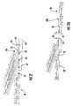
- the base 42has two side walls 43 spanned by a vertical mounting panel 46 that includes mounting apertures 47 .
- the side walls 43have a stair-step profile, with multiple horizontal edges 43 b and vertical edges 43 a (see FIG. 5 ) and are divided into substantially rectangular frangible sections by grooves 48 .
- Each frangible sectionincludes a pivot aperture 44 ; as with the carrier 20 illustrated in FIGS. 1–2A , pivot apertures 44 on one side wall 43 are substantially aligned with pivot apertures 44 on the opposing side wall 43 to form pivot axes B 1 , B 2 , B 3 , B 4 . As can be seen in FIG.
- the pivot apertures 44 on the same side wall 43are offset or staggered from one another, both vertically and horizontally, which in turn causes the pivot axes B 1 , B 2 , B 3 , B 4 to be similarly staggered.
- portions of the edges of the side walls 43 between the horizontal edges 43 b and the vertical edges 43 ainclude detents 45 that are positioned forwardly and upwardly from each pivot aperture 44 .
- the four carrier members 50are substantially identical. As a result, only one carrier member 50 will be described herein; those skilled in this art will appreciate that the discussion is equally applicable to the remaining carrier members 50 .
- Each carrier member 50includes a generally planar main panel 52 .
- a handling tab 54extends upwardly from one end of the main panel 52 .
- two pivot pins 58extend laterally and are inserted into an aligned pair of pivot apertures 44 for pivotal movement about a respective pivot axis B 1 –B 4 .
- two retention pins 60extend laterally from the edges of the main panel 52 adjacent the pivot pins 58 .
- the retention pins 60are sized and positioned to be received in the detents 45 in the side walls 43 or to rest against the horizontal or vertical edges 43 b , 43 a of the side walls 43 , depending on the orientation of the carrier member 50 .
- a latch 56rises from the main panel 52 to capture one edge of a splice tray 62 .
- a nub 55extends slightly from the handling tab 54 toward the latch 56 to capture the opposite edge of the splice tray 62 . As such, the splice tray 62 can be easily snapped into place on the carrier member 50 .
- the carrier 40is mounted such that the carrier members 50 (and, in turn, the splice trays 62 ) are generally horizontally disposed, with the splice trays 62 facing upwardly.
- Each carrier member 50is free to move between an access position, in which the carrier member 50 is generally horizontal (see FIGS. 3 and 6 ) so that the splice tray 62 is accessible, and a partially inverted non-access position, in which the carrier member 50 has rotated about its respective axis of rotation B 1 –B 4 to be generally vertically disposed (see the rearwardmost carrier member 50 in FIG. 4 ) so that the splice tray 62 is not accessible.
- the carrier members 50can be manipulated in “index card” fashion.
- the carrier 40is quite similar to the carrier 20 illustrated in FIGS. 1 and 2 . However, there are some differences that provide additional or alternative functionality to the carrier 40 ; these are described below.
- the presence of the frangible sections in the side walls 43provides the carrier 40 with the capability of being modified as desired by the user for any number of splice trays 62 .
- the usercan simply break off one frangible section from each side wall 43 (for example, section 43 d as designated in FIG. 5 ), which action would leave three pairs of pivot apertures 44 to receive three carrier members 50 and three splice trays 62 .
- Removing frangible sections as describedcan create additional space within the environment in which the carrier 40 resides or permit the carrier 40 to be used in a shallower enclosure.
- the inclusion of the latch 56 and nub 55allow the carrier member 50 to capture the splice tray 62 without the use of an adhesive or other fastener. Because the latch 56 and nub 55 can be formed during the manufacture of the carrier member 50 (particularly if it is formed by the injection molding of a thermoplastic material), components for mounting the splice tray 62 on the carrier member 50 can be formed very inexpensively.
- the mounting apertures 47 on the mounting panel 46can be can be utilized to mount the carrier 40 , typically via screws, other threaded fasteners, push rivets, or the like, to a vertical surface, as can be seen in FIG. 6 .
- a carrier 40 ′may be configured for mounting to a horizontal surface (such as a shelf), as shown in FIG. 7 , via a mounting panel 46 ′ with apertures 47 ′.
- each carrier member 50to be retained in the access and non-access positions as well as an intermediate position.
- the retention pins 60 of each carrier member 50rest against the vertical edges 43 a of the side walls 43 (when the carrier member 50 is disposed as shown in FIG. 6 ), which maintains the carrier members 50 in the access position.
- a slight force applied to the carrier member 50urges it toward the non-access position; this force causes the retention pins 60 to deflect sufficiently to enable them to slide over the end of the horizontal edge to the detents 45 .
- the offset or staggered positioning of the pairs of pivot apertures 44can enable all of the carrier members 50 to overlie one another in stacked, substantially parallel relationship in both the access and non-access positions.
- This fully stacked relationship of the carrier memberscan be realized whether the base 42 is oriented either for wall mounting (see FIG. 6 ) or floor mounting (see FIG. 7 ), with the carrier members 50 being able to pivot from an access position to a non-access position in either orientation.
- the base 42 and carrier members 50can be formed of the same materials discussed above for the carrier 20 .
- many of the design variations discussed above with respect to the carrier 20may also be employed in the carrier 40 .
- the carrier 70is formed from a flexible sheet (typically a flexible polymeric material such as polypropylene) that is folded back upon itself numerous times to form carrier members.
- a flexible sheettypically a flexible polymeric material such as polypropylene
- the carrier 70includes a plurality of carrier members 74 that are interconnected by intermediate panels 76 .
- Each carrier member 74is formed of two overlying panels 74 a , 74 b of a unitary flexible sheet 72 (see FIG. 11 ).
- Each intermediate panel 76is formed of the material of the flexible sheet 72 that resides between adjacent pairs of overlying panels 74 a , 74 b , with adjacent intermediate panels 76 meeting at their edges to form an overall interconnecting member 79 .
- a living hinge 90is formed at the fold lines between adjacent carrier members 74 and intermediate panels 76 that defines a pivot axis C for each of the carrier members 74 .
- the carrier 70also includes a cover panel 78 with a flap 80 and a front panel 81 .
- a hook-and-loop fastener 82is attached to the flap 80
- a mating hook-and-loop fastener 84is attached to the bottom panel 81 .
- the carrier 70is created by folding the flexible sheet 72 into a plurality of leaves to form the carrier members 74 and intermediate panels 76 .
- FIGS. 10A and 10Bshow the configuration of the flexible sheet 72 (typically formed of polypropylene, although other flexible materials may also be employed) prior to folding.
- Designated fold lines 74 cseparate the panels 74 a , 74 b of each carrier member 74
- designated fold lines 74 dseparate the panels 74 a , 74 b from adjacent intermediate panels 76 .
- the cover panel 78is formed by folding the sheet 72 along fold line 78 a
- the flap 80is formed by folding the sheet 72 along fold line 80 a .
- the front panel 81is formed by folding the sheet along fold line 81 a .
- the panels 74 a , 74 bare attached to one another via double-sided adhesive sheets 75 ( FIG. 10B ).
- the carrier members 74may be reinforced by sealing or otherwise attaching the edges of the panels 74 a , 74 b ; it may be particularly advantageous to seal the fold lines 74 d of adjacent panels 74 a , 74 b , as doing so may improve the integrity of the living hinges 90 formed thereby.
- Splice trays 86are mounted to the panel 74 a of each carrier member 74 .
- the splice trays 86are attached via double-sided adhesive sheets 88 (see FIG. 10A ), although other attachment techniques may also be suitable.
- the splice trays 86 and the carrier members 74are in stacked, alternating, generally parallel relationship.
- the intermediate panels 76(not shown in FIG. 8 ) are disposed normal to the carrier members 74 .
- the cover panel 78is parallel to the carrier members 74
- the front panel 81is normal to the carrier members 74 on the side opposite the intermediate panels 76 .
- the flap 80overlies a portion of the front panel 81 such that the fastener 82 mates with the fastener 84 .
- a userIn order to perform work on a splice within the carrier 70 , a user would simply detach the flap 80 from the front panel 81 and rotate the cover panel 78 about its living hinge 90 . Doing so would present the uppermost splice tray 86 to the user. The user would then be free to rifle in “index card” fashion through the splice trays 86 , with each splice tray 86 moving from an access position to a non-access position via rotation about the living hinge 90 of its associated carrier member 74 , until the splice tray 86 of interest were reached.
- the carrier 70can be mounted in a number of orientations, it may be preferred to mount the carrier 70 to a horizontal surface, such as a shelf. If this is the case, one suitable orientation would have the splice trays 86 and carrier members 74 parallel to the mounting surface, with the cover panel 80 facing upwardly. It may also be advantageous to mount the carrier 70 to a vertical surface. If so, one suitable orientation would have the splice trays 86 and carrier members 74 parallel to the mounting surface, with the cover panel 80 facing forwardly and the intermediate panels 76 facing downwardly. In either of these orientations, detachment of the flap 80 from the front panel 81 can provide simple and convenient access to and manipulation of the splice trays 86 .
- the carrier 70can be included in a shelf 110 on an equipment rack 100 .
- This particular shelf 110which is described in greater detail in co-assigned and co-pending U.S. patent application Ser. No. 10/832,893, filed Apr. 27, 2004 and entitled ARTICULATED HIGH DENSITY FIBER OPTIC SPLICE AND TERMINATION SHELF, includes a splice site mounting panel 115 that is vertically oriented during normal operation and during maintenance of the carrier 70 .
- Fiber optic cables 120feed into the carrier 70 , wherein splicing between optical fibers of the fiber optic cables 120 and pigtail fibers 125 is achieved.
- the pigtail fibers 125lead to a termination device 130 , wherein they are optically connected with jumper fibers (not shown).
Landscapes
- Physics & Mathematics (AREA)
- General Physics & Mathematics (AREA)
- Optics & Photonics (AREA)
- Packaging Of Annular Or Rod-Shaped Articles, Wearing Apparel, Cassettes, Or The Like (AREA)
- Light Guides In General And Applications Therefor (AREA)
- Mechanical Coupling Of Light Guides (AREA)
- Packages (AREA)
- Handcart (AREA)
Abstract
Description
Claims (34)
Priority Applications (7)
| Application Number | Priority Date | Filing Date | Title |
|---|---|---|---|
| US10/840,681US7200314B2 (en) | 2004-05-06 | 2004-05-06 | Carrier for multiple splice trays |
| EP05008560AEP1593994A3 (en) | 2004-05-06 | 2005-04-19 | Carrier for multiple splice trays |
| CA2505289ACA2505289C (en) | 2004-05-06 | 2005-04-21 | Carrier for multiple splice trays |
| MXPA05004799AMXPA05004799A (en) | 2004-05-06 | 2005-05-04 | Carrier for multiple splice trays. |
| CNB200510068684XACN100565256C (en) | 2004-05-06 | 2005-05-08 | The carriage that is used for many bond pads |
| US11/367,631US7113687B2 (en) | 2004-05-06 | 2006-03-03 | Carrier for multiple splice trays |
| HK06105189.4AHK1085271B (en) | 2004-05-06 | 2006-05-02 | Carrier for multiple splice trays |
Applications Claiming Priority (1)
| Application Number | Priority Date | Filing Date | Title |
|---|---|---|---|
| US10/840,681US7200314B2 (en) | 2004-05-06 | 2004-05-06 | Carrier for multiple splice trays |
Related Child Applications (1)
| Application Number | Title | Priority Date | Filing Date |
|---|---|---|---|
| US11/367,631DivisionUS7113687B2 (en) | 2004-05-06 | 2006-03-03 | Carrier for multiple splice trays |
Publications (2)
| Publication Number | Publication Date |
|---|---|
| US20050249475A1 US20050249475A1 (en) | 2005-11-10 |
| US7200314B2true US7200314B2 (en) | 2007-04-03 |
Family
ID=34935407
Family Applications (2)
| Application Number | Title | Priority Date | Filing Date |
|---|---|---|---|
| US10/840,681Expired - Fee RelatedUS7200314B2 (en) | 2004-05-06 | 2004-05-06 | Carrier for multiple splice trays |
| US11/367,631Expired - LifetimeUS7113687B2 (en) | 2004-05-06 | 2006-03-03 | Carrier for multiple splice trays |
Family Applications After (1)
| Application Number | Title | Priority Date | Filing Date |
|---|---|---|---|
| US11/367,631Expired - LifetimeUS7113687B2 (en) | 2004-05-06 | 2006-03-03 | Carrier for multiple splice trays |
Country Status (5)
| Country | Link |
|---|---|
| US (2) | US7200314B2 (en) |
| EP (1) | EP1593994A3 (en) |
| CN (1) | CN100565256C (en) |
| CA (1) | CA2505289C (en) |
| MX (1) | MXPA05004799A (en) |
Cited By (46)
| Publication number | Priority date | Publication date | Assignee | Title |
|---|---|---|---|---|
| US20070007291A1 (en)* | 2005-07-01 | 2007-01-11 | Jennifer Gunn | Container for carrying and transporting cupcakes and other pastry items |
| US20100296791A1 (en)* | 2009-05-21 | 2010-11-25 | Elli Makrides-Saravanos | Fiber Optic Equipment Guides and Rails Configured with Stopping Position(s), and Related Equipment and Methods |
| US8184938B2 (en) | 2008-08-29 | 2012-05-22 | Corning Cable Systems Llc | Rear-installable fiber optic modules and equipment |
| US20120169190A1 (en)* | 2010-11-15 | 2012-07-05 | Adc Telecommunications, Inc. | Tray assembly for a fiber optic enclosure |
| US20120301098A1 (en)* | 2010-02-01 | 2012-11-29 | Tyco Electronics Services Gmbh | Support for at least one cassette |
| WO2013036905A1 (en)* | 2011-09-09 | 2013-03-14 | Rich Cubala | Splice tray rail system |
| US8433171B2 (en) | 2009-06-19 | 2013-04-30 | Corning Cable Systems Llc | High fiber optic cable packing density apparatus |
| US8452148B2 (en) | 2008-08-29 | 2013-05-28 | Corning Cable Systems Llc | Independently translatable modules and fiber optic equipment trays in fiber optic equipment |
| US8542973B2 (en) | 2010-04-23 | 2013-09-24 | Ccs Technology, Inc. | Fiber optic distribution device |
| US8593828B2 (en) | 2010-02-04 | 2013-11-26 | Corning Cable Systems Llc | Communications equipment housings, assemblies, and related alignment features and methods |
| US8625950B2 (en) | 2009-12-18 | 2014-01-07 | Corning Cable Systems Llc | Rotary locking apparatus for fiber optic equipment trays and related methods |
| US8660397B2 (en) | 2010-04-30 | 2014-02-25 | Corning Cable Systems Llc | Multi-layer module |
| US8662760B2 (en) | 2010-10-29 | 2014-03-04 | Corning Cable Systems Llc | Fiber optic connector employing optical fiber guide member |
| US8699838B2 (en) | 2009-05-14 | 2014-04-15 | Ccs Technology, Inc. | Fiber optic furcation module |
| US8705926B2 (en) | 2010-04-30 | 2014-04-22 | Corning Optical Communications LLC | Fiber optic housings having a removable top, and related components and methods |
| US8712206B2 (en) | 2009-06-19 | 2014-04-29 | Corning Cable Systems Llc | High-density fiber optic modules and module housings and related equipment |
| US8718436B2 (en) | 2010-08-30 | 2014-05-06 | Corning Cable Systems Llc | Methods, apparatuses for providing secure fiber optic connections |
| US8879881B2 (en) | 2010-04-30 | 2014-11-04 | Corning Cable Systems Llc | Rotatable routing guide and assembly |
| US8913866B2 (en) | 2010-03-26 | 2014-12-16 | Corning Cable Systems Llc | Movable adapter panel |
| US8953924B2 (en) | 2011-09-02 | 2015-02-10 | Corning Cable Systems Llc | Removable strain relief brackets for securing fiber optic cables and/or optical fibers to fiber optic equipment, and related assemblies and methods |
| US8989547B2 (en) | 2011-06-30 | 2015-03-24 | Corning Cable Systems Llc | Fiber optic equipment assemblies employing non-U-width-sized housings and related methods |
| US8985862B2 (en) | 2013-02-28 | 2015-03-24 | Corning Cable Systems Llc | High-density multi-fiber adapter housings |
| US8995812B2 (en) | 2012-10-26 | 2015-03-31 | Ccs Technology, Inc. | Fiber optic management unit and fiber optic distribution device |
| US9008485B2 (en) | 2011-05-09 | 2015-04-14 | Corning Cable Systems Llc | Attachment mechanisms employed to attach a rear housing section to a fiber optic housing, and related assemblies and methods |
| US9020320B2 (en) | 2008-08-29 | 2015-04-28 | Corning Cable Systems Llc | High density and bandwidth fiber optic apparatuses and related equipment and methods |
| US9022814B2 (en) | 2010-04-16 | 2015-05-05 | Ccs Technology, Inc. | Sealing and strain relief device for data cables |
| US9042702B2 (en) | 2012-09-18 | 2015-05-26 | Corning Cable Systems Llc | Platforms and systems for fiber optic cable attachment |
| US9038832B2 (en) | 2011-11-30 | 2015-05-26 | Corning Cable Systems Llc | Adapter panel support assembly |
| US9059578B2 (en) | 2009-02-24 | 2015-06-16 | Ccs Technology, Inc. | Holding device for a cable or an assembly for use with a cable |
| US9075217B2 (en) | 2010-04-30 | 2015-07-07 | Corning Cable Systems Llc | Apparatuses and related components and methods for expanding capacity of fiber optic housings |
| US9075216B2 (en) | 2009-05-21 | 2015-07-07 | Corning Cable Systems Llc | Fiber optic housings configured to accommodate fiber optic modules/cassettes and fiber optic panels, and related components and methods |
| US9116324B2 (en) | 2010-10-29 | 2015-08-25 | Corning Cable Systems Llc | Stacked fiber optic modules and fiber optic equipment configured to support stacked fiber optic modules |
| US9213161B2 (en) | 2010-11-05 | 2015-12-15 | Corning Cable Systems Llc | Fiber body holder and strain relief device |
| US9250409B2 (en) | 2012-07-02 | 2016-02-02 | Corning Cable Systems Llc | Fiber-optic-module trays and drawers for fiber-optic equipment |
| US9279951B2 (en) | 2010-10-27 | 2016-03-08 | Corning Cable Systems Llc | Fiber optic module for limited space applications having a partially sealed module sub-assembly |
| US9519118B2 (en) | 2010-04-30 | 2016-12-13 | Corning Optical Communications LLC | Removable fiber management sections for fiber optic housings, and related components and methods |
| US9632270B2 (en) | 2010-04-30 | 2017-04-25 | Corning Optical Communications LLC | Fiber optic housings configured for tool-less assembly, and related components and methods |
| US9645317B2 (en) | 2011-02-02 | 2017-05-09 | Corning Optical Communications LLC | Optical backplane extension modules, and related assemblies suitable for establishing optical connections to information processing modules disposed in equipment racks |
| US9690065B2 (en) | 2014-09-12 | 2017-06-27 | Panduit Corp. | High density fiber enclosure and method |
| US9720195B2 (en) | 2010-04-30 | 2017-08-01 | Corning Optical Communications LLC | Apparatuses and related components and methods for attachment and release of fiber optic housings to and from an equipment rack |
| US10215944B2 (en) | 2016-06-30 | 2019-02-26 | Panduit Corp. | Modular fiber optic tray |
| US10746949B2 (en) | 2016-12-02 | 2020-08-18 | CommScope Connectivity Belgium BVBA | Optical fiber management systems; and methods |
| US11294135B2 (en) | 2008-08-29 | 2022-04-05 | Corning Optical Communications LLC | High density and bandwidth fiber optic apparatuses and related equipment and methods |
| US20220317403A1 (en)* | 2021-03-31 | 2022-10-06 | Sterlite Technologies Limited | Splice closure with high-density splice cassettes |
| US11716821B1 (en) | 2021-07-21 | 2023-08-01 | The United States Of America As Represented By The Secretary Of The Navy | Compact stackable trays with positioning racks |
| US12353040B2 (en) | 2022-04-11 | 2025-07-08 | Ppc Broadband, Inc. | Adapter configured to permit a heat shrink splice holder portion of a fiber splice cassette to hold a mechanical crimp splice protector |
Families Citing this family (29)
| Publication number | Priority date | Publication date | Assignee | Title |
|---|---|---|---|---|
| US7200314B2 (en)* | 2004-05-06 | 2007-04-03 | Commscope Solutions Properties, Llc | Carrier for multiple splice trays |
| FR2902897B1 (en)* | 2006-06-22 | 2008-12-26 | Nexans Sa | CASSETTE FOR OPTICAL CABLES, SUPPORT RAIL AND STACKING ASSEMBLY OF SUCH CASSETTES |
| DE102007032186A1 (en)* | 2007-03-01 | 2008-12-18 | Adc Gmbh | Support system for fastening fiber optic telecommunications and data equipment, includes profile terminated by specially-shaped U- and V-sections at its ends |
| DE102007010853B4 (en)* | 2007-03-01 | 2009-01-29 | Adc Gmbh | Distributor device for optical waveguides |
| DE102007010855B4 (en)* | 2007-03-01 | 2009-01-08 | Adc Gmbh | Support system for a distributor device for optical waveguides |
| DE102007010863B4 (en)* | 2007-03-01 | 2009-01-08 | Adc Gmbh | Sleeve for fiber optic cable |
| US7418184B1 (en) | 2007-03-15 | 2008-08-26 | Curtis Paul Gonzales | Fiber optic categorization and management tray |
| GB0710990D0 (en)* | 2007-06-08 | 2007-07-18 | Tyco Electronics Raychem Nv | Splice closure and fibre organiser device |
| EP2075608A1 (en) | 2007-12-28 | 2009-07-01 | British Telecmmunications public limited campany | Cable installation using optical detection |
| EP2075606A1 (en) | 2007-12-28 | 2009-07-01 | British Telecmmunications public limited campany | Cable installation using induction |
| EP2277071A2 (en) | 2008-04-21 | 2011-01-26 | ADC Telecommunications, Inc. | Fiber optic splice tray |
| US8086084B2 (en)* | 2008-09-09 | 2011-12-27 | Adc Telecommunications, Inc. | Fiber optic splice tray |
| JP2012503785A (en)* | 2008-09-23 | 2012-02-09 | スリーエム イノベイティブ プロパティズ カンパニー | Fiber distribution enclosure with extractable organizer |
| GB0817639D0 (en) | 2008-09-26 | 2008-11-05 | British Telecomm | Cable installation apparatus |
| MX2011008002A (en)* | 2009-01-28 | 2011-09-15 | Adc Telecommunications Inc | Fiber optic enclosure. |
| EP2230545A1 (en) | 2009-03-19 | 2010-09-22 | BRITISH TELECOMMUNICATIONS public limited company | Passive remote air flow and cable detection |
| GB0905590D0 (en) | 2009-03-31 | 2009-05-13 | British Telecomm | Blown cable apparatus |
| EP2369388A1 (en)* | 2010-03-26 | 2011-09-28 | British Telecommunications public limited company | Optical fibre splice tray assembly |
| FR2960306B1 (en)* | 2010-05-20 | 2013-04-12 | Nexans | OPTICAL FIBER CONNECTION HOUSING |
| US8670644B2 (en)* | 2010-11-23 | 2014-03-11 | Commscope, Inc. Of North Carolina | Manifold for managing fiber optic cable and structures and systems therefor |
| EP3239753B1 (en)* | 2011-02-17 | 2023-11-15 | Bison Patent Licensing, LLC | Optical fiber organizer |
| US9500830B2 (en) | 2012-09-28 | 2016-11-22 | Commscope Technologies Llc | Splice-on cable breakout assembly |
| US11194111B2 (en) | 2017-06-15 | 2021-12-07 | Commscope Technologies Llc | Fiber optic splice closure and assemblies |
| CA3083126A1 (en)* | 2017-11-29 | 2019-06-06 | Prysmian S.P.A. | Power cable joint comprising optical fibers and organizer accommodating them |
| CN108072932B (en)* | 2018-01-22 | 2024-05-24 | 宁波市金泽通信设备有限公司 | Novel optical fiber fusion splice tray |
| US11516327B2 (en)* | 2018-05-01 | 2022-11-29 | Commscope Technologies Llc | Tray tower with position indexing trays |
| EP3948383A4 (en) | 2019-03-29 | 2022-12-07 | CommScope Technologies LLC | Tray hinge interface system |
| CN115524815B (en)* | 2022-09-28 | 2025-08-08 | 惠州市飞博康实业有限公司 | Optical fiber splicing box |
| EP4564071A1 (en)* | 2023-11-29 | 2025-06-04 | Corning Research & Development Corporation | Optical fiber system with fiber optic tray and mount |
Citations (15)
| Publication number | Priority date | Publication date | Assignee | Title |
|---|---|---|---|---|
| US4373776A (en) | 1980-06-30 | 1983-02-15 | Northern Telecom Limited | Protection case for optical fiber splices |
| JPS61204605A (en) | 1985-03-07 | 1986-09-10 | Nippon Telegr & Teleph Corp <Ntt> | Structure of optical fiber core storage part |
| US5071220A (en)* | 1989-05-11 | 1991-12-10 | L'etat Francais Represente Par Le Ministre Des Postes, Des Telecommunications Et Des L'espace (Centre National D'etudes Des Telecommunications) | Joint closure module and box for optical fiber cables |
| US5363466A (en)* | 1992-02-21 | 1994-11-08 | Mars Actel | Assembly of hinged flat modules |
| US5511144A (en)* | 1994-06-13 | 1996-04-23 | Siecor Corporation | Optical distribution frame |
| US5590234A (en)* | 1995-03-31 | 1996-12-31 | Minnesota Mining And Manufacturing Company | Fiber optic splice organizers |
| US6009224A (en)* | 1997-11-06 | 1999-12-28 | Allen; Barry Wayne | Fiber optic organizer with lockable trays and method of accessing a tray |
| US6253016B1 (en)* | 1999-08-31 | 2001-06-26 | Lucent Technologies, Inc. | Wall mounted fiber splice enclosure |
| US6275641B1 (en)* | 1999-08-31 | 2001-08-14 | Lucent Technologies, Inc. | Fiber tray insertion apparatus and method |
| US6275640B1 (en)* | 1999-04-21 | 2001-08-14 | Tyco Electrtonics Corporation | Fiber optic splice closure including end pivoting slack storage holder with adjustable rear wall and associated methods |
| US6418266B1 (en)* | 1999-08-16 | 2002-07-09 | Preformed Line Products Company | Flip tray system for use in an optical fiber splice case |
| US6438310B1 (en)* | 2000-01-24 | 2002-08-20 | Adc Telecommunications, Inc. | Cable management panel with sliding drawer |
| US20020126978A1 (en) | 2001-03-07 | 2002-09-12 | Holman John C. | Cable storage spool |
| US6504986B1 (en)* | 1998-01-21 | 2003-01-07 | Tyco Electronics Corporation | Optical fiber assembly |
| US20060147173A1 (en)* | 2004-05-06 | 2006-07-06 | Womack Wade J | Carrier for multiple splice trays |
Family Cites Families (3)
| Publication number | Priority date | Publication date | Assignee | Title |
|---|---|---|---|---|
| US126978A (en)* | 1872-05-21 | Improvement in chair-backs and cradle-ends | ||
| DE3640836C1 (en)* | 1986-11-29 | 1988-05-26 | Krone Ag | Splice cassette housing for optical fibers |
| GB8729952D0 (en)* | 1987-12-23 | 1988-02-03 | British Telecomm | Mounting assembly for optical equipment |
- 2004
- 2004-05-06USUS10/840,681patent/US7200314B2/ennot_activeExpired - Fee Related
- 2005
- 2005-04-19EPEP05008560Apatent/EP1593994A3/ennot_activeWithdrawn
- 2005-04-21CACA2505289Apatent/CA2505289C/ennot_activeExpired - Fee Related
- 2005-05-04MXMXPA05004799Apatent/MXPA05004799A/enactiveIP Right Grant
- 2005-05-08CNCNB200510068684XApatent/CN100565256C/ennot_activeExpired - Fee Related
- 2006
- 2006-03-03USUS11/367,631patent/US7113687B2/ennot_activeExpired - Lifetime
Patent Citations (16)
| Publication number | Priority date | Publication date | Assignee | Title |
|---|---|---|---|---|
| US4373776A (en) | 1980-06-30 | 1983-02-15 | Northern Telecom Limited | Protection case for optical fiber splices |
| JPS61204605A (en) | 1985-03-07 | 1986-09-10 | Nippon Telegr & Teleph Corp <Ntt> | Structure of optical fiber core storage part |
| US5071220A (en)* | 1989-05-11 | 1991-12-10 | L'etat Francais Represente Par Le Ministre Des Postes, Des Telecommunications Et Des L'espace (Centre National D'etudes Des Telecommunications) | Joint closure module and box for optical fiber cables |
| US5363466A (en)* | 1992-02-21 | 1994-11-08 | Mars Actel | Assembly of hinged flat modules |
| US5511144A (en)* | 1994-06-13 | 1996-04-23 | Siecor Corporation | Optical distribution frame |
| US5590234A (en)* | 1995-03-31 | 1996-12-31 | Minnesota Mining And Manufacturing Company | Fiber optic splice organizers |
| US6009224A (en)* | 1997-11-06 | 1999-12-28 | Allen; Barry Wayne | Fiber optic organizer with lockable trays and method of accessing a tray |
| US6504986B1 (en)* | 1998-01-21 | 2003-01-07 | Tyco Electronics Corporation | Optical fiber assembly |
| US6275640B1 (en)* | 1999-04-21 | 2001-08-14 | Tyco Electrtonics Corporation | Fiber optic splice closure including end pivoting slack storage holder with adjustable rear wall and associated methods |
| US6418266B1 (en)* | 1999-08-16 | 2002-07-09 | Preformed Line Products Company | Flip tray system for use in an optical fiber splice case |
| US6275641B1 (en)* | 1999-08-31 | 2001-08-14 | Lucent Technologies, Inc. | Fiber tray insertion apparatus and method |
| US6253016B1 (en)* | 1999-08-31 | 2001-06-26 | Lucent Technologies, Inc. | Wall mounted fiber splice enclosure |
| US6438310B1 (en)* | 2000-01-24 | 2002-08-20 | Adc Telecommunications, Inc. | Cable management panel with sliding drawer |
| US20020126978A1 (en) | 2001-03-07 | 2002-09-12 | Holman John C. | Cable storage spool |
| US20060147173A1 (en)* | 2004-05-06 | 2006-07-06 | Womack Wade J | Carrier for multiple splice trays |
| US7113687B2 (en)* | 2004-05-06 | 2006-09-26 | Commscope Solutions Properties Llc | Carrier for multiple splice trays |
Non-Patent Citations (5)
| Title |
|---|
| Fibrlok(TM) II Optical Splicing System catalog, 3M, pp. 162-182, no date. |
| Fibrlok™ II Optical Splicing System catalog, 3M, pp. 162-182, no date. |
| Partial European Search Report for European application No. 05 00 8560 completed on Jul. 14, 2005. |
| Partial European Search Report for European patent application No. EP 05 00 8560 completed on Jul. 14, 2005. |
| Richco Fiber Optic Catalog, Edition F01 (2001), no month. |
Cited By (85)
| Publication number | Priority date | Publication date | Assignee | Title |
|---|---|---|---|---|
| US20070007291A1 (en)* | 2005-07-01 | 2007-01-11 | Jennifer Gunn | Container for carrying and transporting cupcakes and other pastry items |
| US11294136B2 (en) | 2008-08-29 | 2022-04-05 | Corning Optical Communications LLC | High density and bandwidth fiber optic apparatuses and related equipment and methods |
| US10564378B2 (en) | 2008-08-29 | 2020-02-18 | Corning Optical Communications LLC | High density and bandwidth fiber optic apparatuses and related equipment and methods |
| US12072545B2 (en) | 2008-08-29 | 2024-08-27 | Corning Optical Communications LLC | High density and bandwidth fiber optic apparatuses and related equipment and methods |
| US10422971B2 (en) | 2008-08-29 | 2019-09-24 | Corning Optical Communicatinos LLC | High density and bandwidth fiber optic apparatuses and related equipment and methods |
| US11294135B2 (en) | 2008-08-29 | 2022-04-05 | Corning Optical Communications LLC | High density and bandwidth fiber optic apparatuses and related equipment and methods |
| US11754796B2 (en) | 2008-08-29 | 2023-09-12 | Corning Optical Communications LLC | Independently translatable modules and fiber optic equipment trays in fiber optic equipment |
| US10094996B2 (en) | 2008-08-29 | 2018-10-09 | Corning Optical Communications, Llc | Independently translatable modules and fiber optic equipment trays in fiber optic equipment |
| US8452148B2 (en) | 2008-08-29 | 2013-05-28 | Corning Cable Systems Llc | Independently translatable modules and fiber optic equipment trays in fiber optic equipment |
| US11609396B2 (en) | 2008-08-29 | 2023-03-21 | Corning Optical Communications LLC | High density and bandwidth fiber optic apparatuses and related equipment and methods |
| US10416405B2 (en) | 2008-08-29 | 2019-09-17 | Corning Optical Communications LLC | Independently translatable modules and fiber optic equipment trays in fiber optic equipment |
| US10120153B2 (en) | 2008-08-29 | 2018-11-06 | Corning Optical Communications, Llc | Independently translatable modules and fiber optic equipment trays in fiber optic equipment |
| US10444456B2 (en) | 2008-08-29 | 2019-10-15 | Corning Optical Communications LLC | High density and bandwidth fiber optic apparatuses and related equipment and methods |
| US8184938B2 (en) | 2008-08-29 | 2012-05-22 | Corning Cable Systems Llc | Rear-installable fiber optic modules and equipment |
| US10126514B2 (en) | 2008-08-29 | 2018-11-13 | Corning Optical Communications, Llc | Independently translatable modules and fiber optic equipment trays in fiber optic equipment |
| US9910236B2 (en) | 2008-08-29 | 2018-03-06 | Corning Optical Communications LLC | High density and bandwidth fiber optic apparatuses and related equipment and methods |
| US10459184B2 (en) | 2008-08-29 | 2019-10-29 | Corning Optical Communications LLC | High density and bandwidth fiber optic apparatuses and related equipment and methods |
| US11092767B2 (en) | 2008-08-29 | 2021-08-17 | Corning Optical Communications LLC | High density and bandwidth fiber optic apparatuses and related equipment and methods |
| US9020320B2 (en) | 2008-08-29 | 2015-04-28 | Corning Cable Systems Llc | High density and bandwidth fiber optic apparatuses and related equipment and methods |
| US11086089B2 (en) | 2008-08-29 | 2021-08-10 | Corning Optical Communications LLC | High density and bandwidth fiber optic apparatuses and related equipment and methods |
| US10852499B2 (en) | 2008-08-29 | 2020-12-01 | Corning Optical Communications LLC | High density and bandwidth fiber optic apparatuses and related equipment and methods |
| US10606014B2 (en) | 2008-08-29 | 2020-03-31 | Corning Optical Communications LLC | Independently translatable modules and fiber optic equipment trays in fiber optic equipment |
| US10222570B2 (en) | 2008-08-29 | 2019-03-05 | Corning Optical Communications LLC | Independently translatable modules and fiber optic equipment trays in fiber optic equipment |
| US9059578B2 (en) | 2009-02-24 | 2015-06-16 | Ccs Technology, Inc. | Holding device for a cable or an assembly for use with a cable |
| US8699838B2 (en) | 2009-05-14 | 2014-04-15 | Ccs Technology, Inc. | Fiber optic furcation module |
| US20100296791A1 (en)* | 2009-05-21 | 2010-11-25 | Elli Makrides-Saravanos | Fiber Optic Equipment Guides and Rails Configured with Stopping Position(s), and Related Equipment and Methods |
| US9075216B2 (en) | 2009-05-21 | 2015-07-07 | Corning Cable Systems Llc | Fiber optic housings configured to accommodate fiber optic modules/cassettes and fiber optic panels, and related components and methods |
| US8538226B2 (en) | 2009-05-21 | 2013-09-17 | Corning Cable Systems Llc | Fiber optic equipment guides and rails configured with stopping position(s), and related equipment and methods |
| US8280216B2 (en) | 2009-05-21 | 2012-10-02 | Corning Cable Systems Llc | Fiber optic equipment supporting moveable fiber optic equipment tray(s) and module(s), and related equipment and methods |
| US8712206B2 (en) | 2009-06-19 | 2014-04-29 | Corning Cable Systems Llc | High-density fiber optic modules and module housings and related equipment |
| US8433171B2 (en) | 2009-06-19 | 2013-04-30 | Corning Cable Systems Llc | High fiber optic cable packing density apparatus |
| US8625950B2 (en) | 2009-12-18 | 2014-01-07 | Corning Cable Systems Llc | Rotary locking apparatus for fiber optic equipment trays and related methods |
| US8934750B2 (en)* | 2010-02-01 | 2015-01-13 | Tyco Electronics Services Gmbh | Support for at least one cassette |
| US20120301098A1 (en)* | 2010-02-01 | 2012-11-29 | Tyco Electronics Services Gmbh | Support for at least one cassette |
| US8992099B2 (en) | 2010-02-04 | 2015-03-31 | Corning Cable Systems Llc | Optical interface cards, assemblies, and related methods, suited for installation and use in antenna system equipment |
| US8593828B2 (en) | 2010-02-04 | 2013-11-26 | Corning Cable Systems Llc | Communications equipment housings, assemblies, and related alignment features and methods |
| US8913866B2 (en) | 2010-03-26 | 2014-12-16 | Corning Cable Systems Llc | Movable adapter panel |
| US9022814B2 (en) | 2010-04-16 | 2015-05-05 | Ccs Technology, Inc. | Sealing and strain relief device for data cables |
| US8542973B2 (en) | 2010-04-23 | 2013-09-24 | Ccs Technology, Inc. | Fiber optic distribution device |
| US9632270B2 (en) | 2010-04-30 | 2017-04-25 | Corning Optical Communications LLC | Fiber optic housings configured for tool-less assembly, and related components and methods |
| US9075217B2 (en) | 2010-04-30 | 2015-07-07 | Corning Cable Systems Llc | Apparatuses and related components and methods for expanding capacity of fiber optic housings |
| US9519118B2 (en) | 2010-04-30 | 2016-12-13 | Corning Optical Communications LLC | Removable fiber management sections for fiber optic housings, and related components and methods |
| US8879881B2 (en) | 2010-04-30 | 2014-11-04 | Corning Cable Systems Llc | Rotatable routing guide and assembly |
| US9720195B2 (en) | 2010-04-30 | 2017-08-01 | Corning Optical Communications LLC | Apparatuses and related components and methods for attachment and release of fiber optic housings to and from an equipment rack |
| US8660397B2 (en) | 2010-04-30 | 2014-02-25 | Corning Cable Systems Llc | Multi-layer module |
| US8705926B2 (en) | 2010-04-30 | 2014-04-22 | Corning Optical Communications LLC | Fiber optic housings having a removable top, and related components and methods |
| US8718436B2 (en) | 2010-08-30 | 2014-05-06 | Corning Cable Systems Llc | Methods, apparatuses for providing secure fiber optic connections |
| US9279951B2 (en) | 2010-10-27 | 2016-03-08 | Corning Cable Systems Llc | Fiber optic module for limited space applications having a partially sealed module sub-assembly |
| US8662760B2 (en) | 2010-10-29 | 2014-03-04 | Corning Cable Systems Llc | Fiber optic connector employing optical fiber guide member |
| US9116324B2 (en) | 2010-10-29 | 2015-08-25 | Corning Cable Systems Llc | Stacked fiber optic modules and fiber optic equipment configured to support stacked fiber optic modules |
| US9213161B2 (en) | 2010-11-05 | 2015-12-15 | Corning Cable Systems Llc | Fiber body holder and strain relief device |
| US8494332B2 (en)* | 2010-11-15 | 2013-07-23 | Adc Telecommunications, Inc. | Tray assembly for a fiber optic enclosure |
| US20120169190A1 (en)* | 2010-11-15 | 2012-07-05 | Adc Telecommunications, Inc. | Tray assembly for a fiber optic enclosure |
| US10481335B2 (en) | 2011-02-02 | 2019-11-19 | Corning Optical Communications, Llc | Dense shuttered fiber optic connectors and assemblies suitable for establishing optical connections for optical backplanes in equipment racks |
| US9645317B2 (en) | 2011-02-02 | 2017-05-09 | Corning Optical Communications LLC | Optical backplane extension modules, and related assemblies suitable for establishing optical connections to information processing modules disposed in equipment racks |
| US9008485B2 (en) | 2011-05-09 | 2015-04-14 | Corning Cable Systems Llc | Attachment mechanisms employed to attach a rear housing section to a fiber optic housing, and related assemblies and methods |
| US8989547B2 (en) | 2011-06-30 | 2015-03-24 | Corning Cable Systems Llc | Fiber optic equipment assemblies employing non-U-width-sized housings and related methods |
| US8953924B2 (en) | 2011-09-02 | 2015-02-10 | Corning Cable Systems Llc | Removable strain relief brackets for securing fiber optic cables and/or optical fibers to fiber optic equipment, and related assemblies and methods |
| WO2013036905A1 (en)* | 2011-09-09 | 2013-03-14 | Rich Cubala | Splice tray rail system |
| US9195020B2 (en) | 2011-09-09 | 2015-11-24 | Afl Telecommunications Llc | Splice tray rail system |
| US9038832B2 (en) | 2011-11-30 | 2015-05-26 | Corning Cable Systems Llc | Adapter panel support assembly |
| US9250409B2 (en) | 2012-07-02 | 2016-02-02 | Corning Cable Systems Llc | Fiber-optic-module trays and drawers for fiber-optic equipment |
| US9042702B2 (en) | 2012-09-18 | 2015-05-26 | Corning Cable Systems Llc | Platforms and systems for fiber optic cable attachment |
| US8995812B2 (en) | 2012-10-26 | 2015-03-31 | Ccs Technology, Inc. | Fiber optic management unit and fiber optic distribution device |
| US8985862B2 (en) | 2013-02-28 | 2015-03-24 | Corning Cable Systems Llc | High-density multi-fiber adapter housings |
| US9690065B2 (en) | 2014-09-12 | 2017-06-27 | Panduit Corp. | High density fiber enclosure and method |
| US10698171B2 (en) | 2014-09-12 | 2020-06-30 | Panduit Corp. | High density fiber enclosure and method |
| US10268013B2 (en) | 2014-09-12 | 2019-04-23 | Panduit Corp. | High density fiber enclosure and method |
| US12228782B2 (en) | 2014-09-12 | 2025-02-18 | Panduit Corp. | High density fiber enclosure and method |
| US10606013B2 (en) | 2014-09-12 | 2020-03-31 | Panduit Corp. | High density fiber enclosure and method |
| US11105995B2 (en) | 2014-09-12 | 2021-08-31 | Panduit Corp. | High density fiber enclosure and method |
| US10317637B2 (en) | 2014-09-12 | 2019-06-11 | Panduit Corp. | High density fiber enclosure and method |
| US11624888B2 (en) | 2014-09-12 | 2023-04-11 | Panduit Corp. | High density fiber enclosure and method |
| US9864158B2 (en) | 2014-09-12 | 2018-01-09 | Panduit Corp. | High density fiber enclosure and method |
| US10768385B2 (en) | 2014-09-12 | 2020-09-08 | Panduit Corp. | High density fiber enclosure and method |
| US11372185B2 (en) | 2016-06-30 | 2022-06-28 | Panduit Corp. | Modular fiber optic tray |
| US10725258B2 (en) | 2016-06-30 | 2020-07-28 | Panduit Corp. | Modular fiber optic tray |
| US11709331B2 (en) | 2016-06-30 | 2023-07-25 | Panduit Corp. | Modular fiber optic tray |
| US10215944B2 (en) | 2016-06-30 | 2019-02-26 | Panduit Corp. | Modular fiber optic tray |
| US12105338B2 (en) | 2016-06-30 | 2024-10-01 | Panduit Corp. | Modular fiber optic tray |
| US11131819B2 (en) | 2016-12-02 | 2021-09-28 | CommScope Connectivity Belgium BVBA | Optical fiber management systems; and methods |
| US10746949B2 (en) | 2016-12-02 | 2020-08-18 | CommScope Connectivity Belgium BVBA | Optical fiber management systems; and methods |
| US20220317403A1 (en)* | 2021-03-31 | 2022-10-06 | Sterlite Technologies Limited | Splice closure with high-density splice cassettes |
| US11716821B1 (en) | 2021-07-21 | 2023-08-01 | The United States Of America As Represented By The Secretary Of The Navy | Compact stackable trays with positioning racks |
| US12353040B2 (en) | 2022-04-11 | 2025-07-08 | Ppc Broadband, Inc. | Adapter configured to permit a heat shrink splice holder portion of a fiber splice cassette to hold a mechanical crimp splice protector |
Also Published As
| Publication number | Publication date |
|---|---|
| CN100565256C (en) | 2009-12-02 |
| CA2505289A1 (en) | 2005-11-06 |
| CA2505289C (en) | 2010-10-19 |
| US20060147173A1 (en) | 2006-07-06 |
| US20050249475A1 (en) | 2005-11-10 |
| EP1593994A3 (en) | 2006-02-08 |
| CN1693933A (en) | 2005-11-09 |
| US7113687B2 (en) | 2006-09-26 |
| EP1593994A2 (en) | 2005-11-09 |
| MXPA05004799A (en) | 2005-12-06 |
| HK1085271A1 (en) | 2006-08-18 |
Similar Documents
| Publication | Publication Date | Title |
|---|---|---|
| US7200314B2 (en) | Carrier for multiple splice trays | |
| US7031588B2 (en) | Articulated high density fiber optic splice and termination shelf | |
| US11448843B2 (en) | Rotatable patch cable holder | |
| US8437595B2 (en) | Fiber management shelf having removable door | |
| US7068907B2 (en) | Optical fiber enclosure system | |
| AU2004264620B2 (en) | Slide arrangement for optical fiber cable drawer | |
| AU2015249095B2 (en) | Multi-layer module | |
| US9075216B2 (en) | Fiber optic housings configured to accommodate fiber optic modules/cassettes and fiber optic panels, and related components and methods | |
| AU2011232444B2 (en) | Moveable adapter panel | |
| US7756380B2 (en) | Hinged cable guide panel providing access to panel rear | |
| US20110268405A1 (en) | Stackable shelves for a fiber optic housing, and related components and methods | |
| US8472776B2 (en) | Wedge shaped fiber retainer ring | |
| US8275230B2 (en) | Stackable optical fiber retainer | |
| US8554042B2 (en) | Optical fiber management shelf including door with push-push fastener | |
| US8953919B2 (en) | Datacommunications modules, cable-connector assemblies and components therefor | |
| HK1085271B (en) | Carrier for multiple splice trays | |
| HK1085016B (en) | Articulated high density fiber optic splice and termination shelf | |
| HK1151099A (en) | Slide arrangement for optical fiber cable drawer | |
| AU2015224448A1 (en) | Stackable shelves for a fiber optic housing, and related components and methods |
Legal Events
| Date | Code | Title | Description |
|---|---|---|---|
| AS | Assignment | Owner name:COMMSCOPE SOLUTIONS PROPERTIES, LLC, NEVADA Free format text:ASSIGNMENT OF ASSIGNORS INTEREST;ASSIGNORS:WOMACK, WADE J.;CASE, RICHARD LEE;REEL/FRAME:015310/0840;SIGNING DATES FROM 20040505 TO 20040506 | |
| STCF | Information on status: patent grant | Free format text:PATENTED CASE | |
| AS | Assignment | Owner name:COMMSCOPE, INC. OF NORTH CAROLINA, NORTH CAROLINA Free format text:MERGER;ASSIGNOR:COMMSCOPE SOLUTIONS PROPERTIES, LLC;REEL/FRAME:019991/0643 Effective date:20061220 Owner name:COMMSCOPE, INC. OF NORTH CAROLINA,NORTH CAROLINA Free format text:MERGER;ASSIGNOR:COMMSCOPE SOLUTIONS PROPERTIES, LLC;REEL/FRAME:019991/0643 Effective date:20061220 | |
| AS | Assignment | Owner name:BANK OF AMERICA, N.A., AS ADMINISTRATIVE AGENT, CA Free format text:SECURITY AGREEMENT;ASSIGNORS:COMMSCOPE, INC. OF NORTH CAROLINA;ALLEN TELECOM, LLC;ANDREW CORPORATION;REEL/FRAME:020362/0241 Effective date:20071227 Owner name:BANK OF AMERICA, N.A., AS ADMINISTRATIVE AGENT,CAL Free format text:SECURITY AGREEMENT;ASSIGNORS:COMMSCOPE, INC. OF NORTH CAROLINA;ALLEN TELECOM, LLC;ANDREW CORPORATION;REEL/FRAME:020362/0241 Effective date:20071227 | |
| FPAY | Fee payment | Year of fee payment:4 | |
| AS | Assignment | Owner name:ANDREW LLC (F/K/A ANDREW CORPORATION), NORTH CAROL Free format text:PATENT RELEASE;ASSIGNOR:BANK OF AMERICA, N.A., AS ADMINISTRATIVE AGENT;REEL/FRAME:026039/0005 Effective date:20110114 Owner name:ALLEN TELECOM LLC, NORTH CAROLINA Free format text:PATENT RELEASE;ASSIGNOR:BANK OF AMERICA, N.A., AS ADMINISTRATIVE AGENT;REEL/FRAME:026039/0005 Effective date:20110114 Owner name:COMMSCOPE, INC. OF NORTH CAROLINA, NORTH CAROLINA Free format text:PATENT RELEASE;ASSIGNOR:BANK OF AMERICA, N.A., AS ADMINISTRATIVE AGENT;REEL/FRAME:026039/0005 Effective date:20110114 | |
| AS | Assignment | Owner name:JPMORGAN CHASE BANK, N.A., AS COLLATERAL AGENT, NE Free format text:SECURITY AGREEMENT;ASSIGNORS:ALLEN TELECOM LLC, A DELAWARE LLC;ANDREW LLC, A DELAWARE LLC;COMMSCOPE, INC. OF NORTH CAROLINA, A NORTH CAROLINA CORPORATION;REEL/FRAME:026276/0363 Effective date:20110114 | |
| AS | Assignment | Owner name:JPMORGAN CHASE BANK, N.A., AS COLLATERAL AGENT, NE Free format text:SECURITY AGREEMENT;ASSIGNORS:ALLEN TELECOM LLC, A DELAWARE LLC;ANDREW LLC, A DELAWARE LLC;COMMSCOPE, INC OF NORTH CAROLINA, A NORTH CAROLINA CORPORATION;REEL/FRAME:026272/0543 Effective date:20110114 | |
| FPAY | Fee payment | Year of fee payment:8 | |
| AS | Assignment | Owner name:WILMINGTON TRUST, NATIONAL ASSOCIATION, AS COLLATERAL AGENT, CONNECTICUT Free format text:SECURITY INTEREST;ASSIGNORS:ALLEN TELECOM LLC;COMMSCOPE TECHNOLOGIES LLC;COMMSCOPE, INC. OF NORTH CAROLINA;AND OTHERS;REEL/FRAME:036201/0283 Effective date:20150611 Owner name:WILMINGTON TRUST, NATIONAL ASSOCIATION, AS COLLATE Free format text:SECURITY INTEREST;ASSIGNORS:ALLEN TELECOM LLC;COMMSCOPE TECHNOLOGIES LLC;COMMSCOPE, INC. OF NORTH CAROLINA;AND OTHERS;REEL/FRAME:036201/0283 Effective date:20150611 | |
| AS | Assignment | Owner name:COMMSCOPE, INC. OF NORTH CAROLINA, NORTH CAROLINA Free format text:RELEASE OF SECURITY INTEREST PATENTS (RELEASES RF 036201/0283);ASSIGNOR:WILMINGTON TRUST, NATIONAL ASSOCIATION;REEL/FRAME:042126/0434 Effective date:20170317 Owner name:ALLEN TELECOM LLC, NORTH CAROLINA Free format text:RELEASE OF SECURITY INTEREST PATENTS (RELEASES RF 036201/0283);ASSIGNOR:WILMINGTON TRUST, NATIONAL ASSOCIATION;REEL/FRAME:042126/0434 Effective date:20170317 Owner name:REDWOOD SYSTEMS, INC., NORTH CAROLINA Free format text:RELEASE OF SECURITY INTEREST PATENTS (RELEASES RF 036201/0283);ASSIGNOR:WILMINGTON TRUST, NATIONAL ASSOCIATION;REEL/FRAME:042126/0434 Effective date:20170317 Owner name:COMMSCOPE TECHNOLOGIES LLC, NORTH CAROLINA Free format text:RELEASE OF SECURITY INTEREST PATENTS (RELEASES RF 036201/0283);ASSIGNOR:WILMINGTON TRUST, NATIONAL ASSOCIATION;REEL/FRAME:042126/0434 Effective date:20170317 | |
| FEPP | Fee payment procedure | Free format text:MAINTENANCE FEE REMINDER MAILED (ORIGINAL EVENT CODE: REM.); ENTITY STATUS OF PATENT OWNER: LARGE ENTITY | |
| AS | Assignment | Owner name:REDWOOD SYSTEMS, INC., NORTH CAROLINA Free format text:RELEASE BY SECURED PARTY;ASSIGNOR:JPMORGAN CHASE BANK, N.A.;REEL/FRAME:048840/0001 Effective date:20190404 Owner name:ALLEN TELECOM LLC, ILLINOIS Free format text:RELEASE BY SECURED PARTY;ASSIGNOR:JPMORGAN CHASE BANK, N.A.;REEL/FRAME:048840/0001 Effective date:20190404 Owner name:ANDREW LLC, NORTH CAROLINA Free format text:RELEASE BY SECURED PARTY;ASSIGNOR:JPMORGAN CHASE BANK, N.A.;REEL/FRAME:048840/0001 Effective date:20190404 Owner name:COMMSCOPE, INC. OF NORTH CAROLINA, NORTH CAROLINA Free format text:RELEASE BY SECURED PARTY;ASSIGNOR:JPMORGAN CHASE BANK, N.A.;REEL/FRAME:048840/0001 Effective date:20190404 Owner name:COMMSCOPE TECHNOLOGIES LLC, NORTH CAROLINA Free format text:RELEASE BY SECURED PARTY;ASSIGNOR:JPMORGAN CHASE BANK, N.A.;REEL/FRAME:048840/0001 Effective date:20190404 Owner name:REDWOOD SYSTEMS, INC., NORTH CAROLINA Free format text:RELEASE BY SECURED PARTY;ASSIGNOR:JPMORGAN CHASE BANK, N.A.;REEL/FRAME:049260/0001 Effective date:20190404 Owner name:ANDREW LLC, NORTH CAROLINA Free format text:RELEASE BY SECURED PARTY;ASSIGNOR:JPMORGAN CHASE BANK, N.A.;REEL/FRAME:049260/0001 Effective date:20190404 Owner name:ALLEN TELECOM LLC, ILLINOIS Free format text:RELEASE BY SECURED PARTY;ASSIGNOR:JPMORGAN CHASE BANK, N.A.;REEL/FRAME:049260/0001 Effective date:20190404 Owner name:COMMSCOPE, INC. OF NORTH CAROLINA, NORTH CAROLINA Free format text:RELEASE BY SECURED PARTY;ASSIGNOR:JPMORGAN CHASE BANK, N.A.;REEL/FRAME:049260/0001 Effective date:20190404 Owner name:COMMSCOPE TECHNOLOGIES LLC, NORTH CAROLINA Free format text:RELEASE BY SECURED PARTY;ASSIGNOR:JPMORGAN CHASE BANK, N.A.;REEL/FRAME:049260/0001 Effective date:20190404 | |
| LAPS | Lapse for failure to pay maintenance fees | Free format text:PATENT EXPIRED FOR FAILURE TO PAY MAINTENANCE FEES (ORIGINAL EVENT CODE: EXP.); ENTITY STATUS OF PATENT OWNER: LARGE ENTITY | |
| STCH | Information on status: patent discontinuation | Free format text:PATENT EXPIRED DUE TO NONPAYMENT OF MAINTENANCE FEES UNDER 37 CFR 1.362 | |
| FP | Lapsed due to failure to pay maintenance fee | Effective date:20190403 | |
| AS | Assignment | Owner name:WILMINGTON TRUST, NATIONAL ASSOCIATION, AS COLLATE Free format text:PATENT SECURITY AGREEMENT;ASSIGNOR:COMMSCOPE, INC. OF NORTH CAROLINA;REEL/FRAME:049678/0577 Effective date:20190404 Owner name:JPMORGAN CHASE BANK, N.A., NEW YORK Free format text:TERM LOAN SECURITY AGREEMENT;ASSIGNORS:COMMSCOPE, INC. OF NORTH CAROLINA;COMMSCOPE TECHNOLOGIES LLC;ARRIS ENTERPRISES LLC;AND OTHERS;REEL/FRAME:049905/0504 Effective date:20190404 Owner name:JPMORGAN CHASE BANK, N.A., NEW YORK Free format text:ABL SECURITY AGREEMENT;ASSIGNORS:COMMSCOPE, INC. OF NORTH CAROLINA;COMMSCOPE TECHNOLOGIES LLC;ARRIS ENTERPRISES LLC;AND OTHERS;REEL/FRAME:049892/0396 Effective date:20190404 Owner name:WILMINGTON TRUST, NATIONAL ASSOCIATION, AS COLLATERAL AGENT, CONNECTICUT Free format text:PATENT SECURITY AGREEMENT;ASSIGNOR:COMMSCOPE, INC. OF NORTH CAROLINA;REEL/FRAME:049678/0577 Effective date:20190404 | |
| AS | Assignment | Owner name:RUCKUS WIRELESS, LLC (F/K/A RUCKUS WIRELESS, INC.), NORTH CAROLINA Free format text:RELEASE OF SECURITY INTEREST AT REEL/FRAME 049905/0504;ASSIGNOR:JPMORGAN CHASE BANK, N.A., AS COLLATERAL AGENT;REEL/FRAME:071477/0255 Effective date:20241217 Owner name:COMMSCOPE TECHNOLOGIES LLC, NORTH CAROLINA Free format text:RELEASE OF SECURITY INTEREST AT REEL/FRAME 049905/0504;ASSIGNOR:JPMORGAN CHASE BANK, N.A., AS COLLATERAL AGENT;REEL/FRAME:071477/0255 Effective date:20241217 Owner name:COMMSCOPE, INC. OF NORTH CAROLINA, NORTH CAROLINA Free format text:RELEASE OF SECURITY INTEREST AT REEL/FRAME 049905/0504;ASSIGNOR:JPMORGAN CHASE BANK, N.A., AS COLLATERAL AGENT;REEL/FRAME:071477/0255 Effective date:20241217 Owner name:ARRIS SOLUTIONS, INC., NORTH CAROLINA Free format text:RELEASE OF SECURITY INTEREST AT REEL/FRAME 049905/0504;ASSIGNOR:JPMORGAN CHASE BANK, N.A., AS COLLATERAL AGENT;REEL/FRAME:071477/0255 Effective date:20241217 Owner name:ARRIS TECHNOLOGY, INC., NORTH CAROLINA Free format text:RELEASE OF SECURITY INTEREST AT REEL/FRAME 049905/0504;ASSIGNOR:JPMORGAN CHASE BANK, N.A., AS COLLATERAL AGENT;REEL/FRAME:071477/0255 Effective date:20241217 Owner name:ARRIS ENTERPRISES LLC (F/K/A ARRIS ENTERPRISES, INC.), NORTH CAROLINA Free format text:RELEASE OF SECURITY INTEREST AT REEL/FRAME 049905/0504;ASSIGNOR:JPMORGAN CHASE BANK, N.A., AS COLLATERAL AGENT;REEL/FRAME:071477/0255 Effective date:20241217 |