US7200207B2 - Communication network for providing emergency services - Google Patents
Communication network for providing emergency servicesDownload PDFInfo
- Publication number
- US7200207B2 US7200207B2US10/816,613US81661304AUS7200207B2US 7200207 B2US7200207 B2US 7200207B2US 81661304 AUS81661304 AUS 81661304AUS 7200207 B2US7200207 B2US 7200207B2
- Authority
- US
- United States
- Prior art keywords
- response
- ces
- gateway
- media channel
- communication network
- Prior art date
- Legal status (The legal status is an assumption and is not a legal conclusion. Google has not performed a legal analysis and makes no representation as to the accuracy of the status listed.)
- Expired - Lifetime, expires
Links
Images


Classifications
- H—ELECTRICITY
- H04—ELECTRIC COMMUNICATION TECHNIQUE
- H04M—TELEPHONIC COMMUNICATION
- H04M3/00—Automatic or semi-automatic exchanges
- H04M3/42—Systems providing special services or facilities to subscribers
- H04M3/50—Centralised arrangements for answering calls; Centralised arrangements for recording messages for absent or busy subscribers ; Centralised arrangements for recording messages
- H04M3/51—Centralised call answering arrangements requiring operator intervention, e.g. call or contact centers for telemarketing
- H04M3/5116—Centralised call answering arrangements requiring operator intervention, e.g. call or contact centers for telemarketing for emergency applications
- H—ELECTRICITY
- H04—ELECTRIC COMMUNICATION TECHNIQUE
- H04W—WIRELESS COMMUNICATION NETWORKS
- H04W4/00—Services specially adapted for wireless communication networks; Facilities therefor
- H04W4/90—Services for handling of emergency or hazardous situations, e.g. earthquake and tsunami warning systems [ETWS]
- H—ELECTRICITY
- H04—ELECTRIC COMMUNICATION TECHNIQUE
- H04M—TELEPHONIC COMMUNICATION
- H04M11/00—Telephonic communication systems specially adapted for combination with other electrical systems
- H04M11/04—Telephonic communication systems specially adapted for combination with other electrical systems with alarm systems, e.g. fire, police or burglar alarm systems
Definitions
- the inventionis related to the field of emergency services, and in particular, to a communication network for providing emergency services.
- basic 9-1-1 serviceis an emergency reporting service where a calling party can dial 9-1-1 in emergency situations.
- the callis answered at a Public Safety Answering Point (PSAP, also known as a “Public Safety Access Point”).
- PSAPPublic Safety Answering Point
- An operator at the PSAPconverses with the calling party to determine information on the emergency situation. For instance, the operator may ask the calling party for his/her name, the nature of the emergency, and the location of the emergency, etc. Based on the information gathered by the operator, the operator then contacts emergency personnel to respond to the emergency.
- E9-1-1 servicehas the added feature of automatically providing the operator with some information on the calling party.
- E9-1-1 serviceincludes the added features of Automatic Number Identification (ANI) and Automatic Location Identification (ALI).
- ANIAutomatic Number Identification
- ALIAutomatic Location Identification
- the PSAPqueries an ALI database for information on the physical location of the calling party's phone.
- An ALI databasestores records of telephone numbers.
- a record in the ALI databasecontains information (such as a street address) on a physical location that corresponds with a telephone number. Responsive to a query from the PSAP, the ALI database returns the location information for the calling party. With the telephone number and the location information, the operator can more effectively handle the emergency call. Other countries have emergency services similar to this.
- a PSAPconnects to a pair of ALI databases in the emergency services network.
- a pair of ALI databasesis used for redundancy and reliability.
- the PSAPconnects to each ALI database over a dedicated point-to-point connection.
- the ALI databasesare the only resources in the emergency services network that connect with the PSAP and that can serve a request from the PSAP.
- the PSAPis not able to dynamically connect with other ALI databases or other resources in the emergency services network.
- the PSAPis unfortunately dependant on the pair of ALI databases to provide information for a 9-1-1 call.
- the inventionhelps solve the above and other problems with a communication network having an improved interface between conforming emergency systems (e.g., a PSAP) and emergency services of an emergency services network.
- conforming emergency systemsmay communicate with more than just a pair of ALI databases.
- conforming emergency systemsare not reliant on the pair of ALI databases as the sole interface to emergency services of an emergency services network.
- conforming emergency systemswould not be left one-sided if an ALI database were to be taken out of service.
- One embodiment of the inventioncomprises a communication network that includes a plurality of conforming emergency systems, a packet network, and an emergency services network.
- the emergency services networkincludes a plurality of response gateways and a plurality of emergency services.
- Each of the conforming emergency systemsfacilitates the establishment of a media channel with one of the response gateways over the packet network to interface with the emergency services network.
- the conforming emergency systemresponsive to establishing a media channel with a response gateway and responsive to an emergency event (e.g., a 9-1-1 call, a 1-1-2 call, a request for emergency information, etc), transmits a retrieval key over the established media channel to the response gateway.
- the response gatewaytransmits a query for information corresponding with the retrieval key within the emergency services network.
- the querymay be transmitted to the emergency services or to another system that queries the emergency services for the response gateway. Responsive to receiving information originating from the individual emergency services corresponding with the retrieval key, the response gateway transmits the information over the media channel to the conforming emergency system. When the conforming emergency system receives the information corresponding with the retrieval key, the conforming emergency system can use the information to handle the emergency event.
- the inventionincludes other networks, systems, and methods described below.
- FIG. 1illustrates a communication network that provides emergency services in the prior art, such as 9-1-1 service in the United States.
- FIG. 2illustrates a communication network in an exemplary embodiment of the invention.
- FIG. 3is a flow chart illustrating a method of operating the communication network in an exemplary embodiment of the invention.
- FIG. 4is a flow chart illustrating a method for dynamically establishing a media channel between a conforming emergency system and a response gateway in an exemplary embodiment of the invention.
- FIG. 5illustrates a communication network that further includes a channel setup system in an exemplary embodiment of the invention.
- FIG. 6is a flow chart illustrating a method for dynamically establishing a media channel using a channel setup system in an exemplary embodiment of the invention.
- FIG. 7illustrates a channel setup system in an exemplary embodiment of the invention.
- FIG. 8illustrates a communication network that further includes an SNR system in an exemplary embodiment of the invention.
- FIG. 9is a flow chart illustrating communications in the communication network of FIG. 8 in an exemplary embodiment of the invention.
- FIG. 10is a flow chart illustrating a method in one exemplary embodiment of the invention.
- FIG. 11is a flow chart illustrating another method in another exemplary embodiment of the invention.
- FIG. 12is a flow chart illustrating another method in another exemplary embodiment of the invention.
- FIG. 1illustrates a prior art communication network 100 that provides emergency services.
- Communication network 100includes a telephone 102 , a selective router (SR) 104 , a Public Safety Answering Point (PSAP) 106 , and an emergency services network 108 .
- Emergency services network 108includes two ALI databases 121 – 122 , a Mobile Positioning Center (MPC) 124 (or a Gateway Mobile Location Center (GMLC)), a supplemental information provider 128 , and other backend resources (not shown). Although a single MPC 124 and a single supplemental information provider 128 are illustrated in FIG. 1 , emergency services network 108 generally includes multiple MPCs and supplemental information providers.
- telephone 102is connected to selective router 104 .
- Selective router 104is connected to PSAP 106 and ALI databases 121 – 122 .
- PSAP 106is connected to ALI databases 121 – 122 .
- ALI database 121is connected to ALI database 122 , MPC 124 , and supplemental information provider 128 .
- ALI database 122is connected to ALI database 121 , MPC 124 , and supplemental information provider 128 .
- Paired ALI databases 121 – 122are used in emergency services networks, such as emergency service network 108 , to add redundancy and reliability into the network.
- Each PSAP 106(only one is shown) connects to two ALI databases 121 – 122 .
- PSAP 106is connected to ALI database 121 by a dedicated point-to-point connection 131 , and is connected to ALI database 122 by a dedicated point-to-point connection 132 .
- the PSAP-ALI interfacetraditionally includes fixed point-to-point data circuits utilizing asynchronous data modems for the dedicated connections 131 – 132 .
- dedicated connections 131 – 132may include an upgraded transport protocol, such as Internet Protocol (IP) or X.25. Regardless of the transport protocol, the logical connections between PSAP 106 and ALI databases 121 – 122 remain point-to-point dedicated connections 131 – 132 .
- IPInternet Protocol
- X.25X.25
- Selective router 104receives the emergency call, such as through a central office (not shown), a tandem switch (not shown), etc. Selective router 104 also receives an Emergency Service Number (ESN) associated with the location of the calling party from one or more ALI databases 121 – 122 or from another database (not shown). In FIG. 1 , based on the ESN, selective router 104 selects PSAP 106 to handle the call and routes the emergency call to PSAP 106 . Networks may route the emergency call to PSAP 106 in different ways depending on the desired implementation. Some examples of different implementations are illustrated in U.S. Pat. No.
- ESNEmergency Service Number
- Emergency services network 108which provides E9-1-1 services, includes Automatic Location Identification (ALI) services.
- PSAP 106When PSAP 106 receives the emergency call, PSAP 106 also receives an ANI for the call.
- the ANIwhich is the telephone number of the calling party telephone 102 , allows an operator in PSAP 106 to call the calling party back if the call happens to be terminated.
- the ANIalso allows the PSAP 106 to fetch information on the physical location of the calling party in order to dispatch the appropriate emergency personnel (e.g., police, ambulance, fire department).
- PSAP 106To fetch the location information, PSAP 106 generates a request for the location information that includes the ANI of telephone 102 , and forwards the request to ALI database 121 over dedicated connection 131 .
- PSAP 106may forward the request to ALI database 122 over dedicated connection 132 in addition to forwarding the request to ALI database 121 or instead of forwarding the request to ALI database 121 .
- ALI database 121receives the request for location information that includes the ANI. ALI database 121 searches for location information corresponding with the ANI. If ALI database 121 finds location information corresponding with the ANI, then ALI database 121 responds to PSAP 106 with the location information. If ALI database 121 does not find location information corresponding with the ANI, then ALI database 121 may have to query other ALI databases or other databases or systems for the location information.
- ALI database 121acts as an intermediary between PSAP 106 and the other emergency services in emergency services network 108 .
- PSAP 106does not directly connect with emergency services other than ALI databases 121 – 122 .
- PSAP 106communicates with MPC 124 and supplemental information provider 128 through one or both of ALI databases 121 – 122 .
- MPC 124For instance, if telephone 102 is a mobile phone, then ALI database 121 queries MPC 124 or another MPC (not shown) for location information corresponding with the ANI and forwards the location information to PSAP 106 .
- ALI database 121may provide supplemental information provider 128 with the ANI, and supplemental information provide 128 may provide services such as notifying third parties of the emergency call. In each of these cases, ALI database 121 interfaces PSAP 106 with the other emergency services.
- PSAP 106When PSAP 106 receives a response from ALI database 121 , PSAP 106 should be better informed to handle the emergency call. For instance, PSAP 106 should have location information for the calling party. PSAP 106 then informs the appropriate emergency personnel of the emergency call so that the emergency personnel can be quickly dispatched.
- PSAP-ALI interfaceuses dedicated point-to-point connections 131 – 132 between PSAP 106 and ALI databases 121 – 122 .
- PSAP 106is not able to dynamically connect with another ALI database (not shown) or another resource in emergency services network 108 .
- PSAP 106is dependant on the pair of ALI databases 121 – 122 to provide information for an emergency call. If one of the ALI databases 121 were to be taken out of service for maintenance or upgrades, then PSAP 106 would be connected to a single ALI database 122 and become one-sided. If the remaining ALI database 122 was to go out of service, then PSAP 106 would not be able to adequately service emergency calls.
- Emergency services administratorstry to avoid architectures that rely on a single device or system because of the higher possibility of a service outage.
- PSAP-ALI interfaceuses a limited message set.
- Most conventional PSAPsfundamentally include the same design as when they were initially conceived in the 1970's.
- the conventional PSAPsare configured to receive a fixed-length, pre-defined text string.
- the fixed-length text stringlimits the number of fields and the size of the fields that can be included in the text string.
- the small size of the text streamseverely constrains the amount of information that the ALI database can provide to the PSAP, the context that can be created, and the data types that can be supported.
- Emergency services administratorshave had to “overload” the text string, using the same fixed-length field for multiple purposes in different contexts, to provide the current services.
- New services or new capabilitiesare very difficult to add if the text string is overloaded by the current services. For instance, an ALI database would not be able to provide or would only be able to provide very limited individual medical information to the PSAP. Also, the technology does not lend itself to streaming video to the PSAP as the traditional message set does not have the capacity.
- the PSAP-ALI interface modelis a request-response model.
- the PSAPforwards a request for ALI information to the ALI database, and the ALI database provides a response to the PSAP.
- the PSAPhas to initiate communication with the ALI database with a request for ALI information.
- the ALI databaseis not allowed or equipped to initiate a communication with the PSAP, or deliver ALI information to the PSAP unless the PSAP submits a request.
- the current PSAP-ALI interface modellimits the types of enhanced services provided by the emergency services network.
- telephone 102comprises a mobile telephone and that a user of telephone 102 dials 9-1-1.
- Selective router 104routes the 9-1-1 call to PSAP 106 .
- PSAP 106submits a request to ALI database 121 for information for the 9-1-1 call.
- the requestincludes an ANI.
- ALI database 121determines that the ANI is a pseudo-ANI corresponding with a wireless service provider for telephone 102 .
- the ANIis not the actual telephone number of telephone 102 , but is a key corresponding with basic information identifying the wireless service provider and/or identifying the cell tower from which the 9-1-1 call originated.
- ALI database 121does not have location information for the pseudo-ANI. Consequently, ALI database 121 cannot immediately provide the location information to PSAP 106 because it must attempt to retrieve location information for telephone 102 . ALI database 121 retrieves the location information by submitting a request to the wireless service provider's MPC 124 . Because the PSAP-ALI interface allows only one response to a request, ALI database 121 attempts to collect all call information before responding to PSAP 106 . ALI database 121 also attempts to ensure that PSAP 106 receives a response within a reasonable amount of time. Before submitting the request to MPC 124 , ALI database 121 sets a timer to indicate how long it will wait for MPC 124 to respond.
- ALI database 121responds to PSAP 106 with the location information on telephone 102 .
- the location informationmay be approximate X, Y coordinates (longitude and latitude) of telephone 102 (assuming a wireless Phase II system).
- ALI database 121responds to PSAP 106 with basic call information.
- the basic call informationdoes not specify the location of telephone 102 .
- the basic call informationmay merely be information on the wireless service provider or information on the cell tower from which the 9-1-1 call originated.
- MPC 124responds to ALI database 121 with the location information after ALI database 121 has already responded to PSAP 106 with the basic information, ALI database 121 cannot provide the location information on telephone 102 to PSAP 106 .
- ALI database 121cannot transmit information to PSAP 106 unless PSAP 106 has previously transmitted a request to ALI database 121 that remains unanswered.
- PSAP 106will have to submit another request to ALI database 121 for the same information (sometimes referred to as a re-bid).
- ALI database 121If ALI database 121 receives another request from PSAP 106 , then ALI database 121 will need to determine whether to send the previous location information received from MPC 124 , request new location information from MPC 124 , handle time-out scenarios, and handle situations where this request may be for a new 9-1-1 call using the same pseudo-ANI. This scenario is further complicated because the ALI database 121 does not know when this call ends and another call with the same pseudo-ANI begins. Thus, ALI database 121 uses an elaborate scheme of timers to determine if the information received from MPC 124 is stale, and determines whether it should return the information for subsequent requests from PSAP 106 or whether it should submit new requests to MPC 124 .
- ALI database 121While ALI database 121 is requesting information from MPC 124 and PSAP 106 is waiting for a response, PSAP 106 may be connected with a calling party possibly engaged in a life or death situation where any bit of information might help determine the best course of action. ALI database 121 cannot tell that it takes more time to determine location information for telephone 102 because of technology overhead. PSAP 106 may have to wait 10 to 15 seconds to be told nothing more than that the 9-1-1 call is a wireless call.
- the PSAP-ALI interfaceputs the PSAP operator in a guessing game.
- the PSAP operatordoes not know when the wireless call location information becomes available and does not know how often re-bids should be submitted to receive initial or new information.
- PSAP operatorsare taught not to push the re-bid button repeatedly in hopes of getting caller information, as this could have the opposite effect and swamp ALI database 121 or MPC 124 in a manner such that PSAP 106 cannot receive a response.
- the current emergency services networksuse old technology, are not very flexible in updating or improving existing services, and are not readily expandable to add new and better services.
- the importance of emergency services networksdemands that these networks evolve to provide the best and most reliable services.
- FIGS. 2–12 and the following descriptiondepict specific embodiments of the invention to teach those skilled in the art how to make and use the best mode of the invention. For the purpose of teaching inventive principles, some conventional aspects of the invention have been simplified or omitted. Those skilled in the art will appreciate variations from these embodiments that fall within the scope of the invention. Those skilled in the art will appreciate that the features described below can be combined in various ways to form multiple variations of the invention. As a result, the invention is not limited to the specific embodiments described below, but only by the claims and their equivalents.
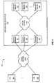
- FIG. 2illustrates a communication network 200 in an exemplary embodiment of the invention.
- Communication network 202includes a plurality of conforming emergency systems (CES) 201 – 202 , a packet network 210 a , and an emergency services network 220 .
- Emergency services network 220includes a plurality of response gateways 221 – 223 and a plurality of emergency services 231 – 122 .
- CESs 201 - 2 - 2 and response gateways 221 – 223are connected to packet network 210 a .
- Emergency services 231 – 233are shown as connected to packet network 210 b , but emergency services 231 – 233 may be connected to response gateways 221 – 223 over a network other than a packet network.
- Communication network 200may include other devices, resources, or systems not shown in FIG. 2 for the sake of brevity.
- FIG. 2is intended to illustrate communications network 200 in a more functional manner than a physical manner.
- response gateway 221may be part of CES 201 , may be part of emergency services 231 – 233 , or an independent system.
- a conforming emergency systemcomprises any system, device, or equipment configured to communicate according to the message set used by an emergency services network to access emergency services (not shown) to handle emergency events.
- a conforming emergency systemis a computer system for a Public Safety Answering Point (PSAP) conforming to the message set used by an emergency services network.
- PSAPPublic Safety Answering Point
- a PSAPis known in the art of emergency services as a location where an emergency call (e.g., a 9-1-1 call) is answered.
- a conforming emergency systemis a computer system for a hospital, a police department, a fire station, a fire alarm company, a security company, an ambulance service, a state 9-1-1 coordinator, the Federal Emergency Management Agency (FEMA), the Department of Homeland Security, the National Geophysical Data Center, the Center for Disease Control (CDC), etc, that conforms to the message set used by an emergency services network and is used to access in emergency services to handle emergency events.
- An emergency eventcomprises any instance or situation where a request for emergency services may be made.
- Examples of an emergency eventinclude any abbreviated number call (e.g., a 9-1-1 call in the U.S., a 3-1-1 call in the U.S., and a 1-1-2 call in Europe), any call or request from a computer, a PDA, a TDD device, or any other device for emergency services, an email message, an SMS message, an Internet message, a call or signal to an emergency call center (e.g., an independent alarm service, OnStar®, etc), or any other request for emergency services.
- an abbreviated number calle.g., a 9-1-1 call in the U.S., a 3-1-1 call in the U.S., and a 1-1-2 call in Europe
- any call or request from a computere.g., a PDA, a TDD device, or any other device for emergency services
- an email messagee.g., an SMS message, an Internet message
- a call or signal to an emergency call centere.g., an independent alarm service, On
- a packet networkcomprises any network that transports messages in the form of packets or cells.
- Examples of a packet networkinclude an Internet Protocol (IP) network, a frame relay network, an X.25 network, an Asynchronous Transfer Mode (ATM) network, etc.
- IPInternet Protocol
- ATMAsynchronous Transfer Mode
- Packet networks 210 a and 210 bare illustrated herein as separate networks. Packet networks 210 a and 210 b may be two isolated networks, may be two networks that communicate with each other via, for, example a gateway (not shown but well known in the art) or may be two parts of a single network.
- a response gatewaycomprises any system, server, or equipment configured to communicate with a conforming emergency system via a media channel over a packet network, and interface the conforming emergency system with emergency services of an emergency services network.
- a media channelcomprises any communication path or paths (logical, virtual, or otherwise) over a transport network configured to transport data such as streaming video, streaming audio, voice, graphics, text data, binary data, executable instructions or scripts, etc.
- a media channelis not a physical or logical point-to-point dedicated connection over a transport network.
- the media channelmay transport control messages or may operate in conjunction with a separate control channel.
- An emergency services networkincludes any network or networks that provide emergency services or facilitates a conforming emergency system in handling emergency events.
- Emergency servicescomprise any services subscribed to or provided for an emergency call or other event requiring such services.
- An emergency serviceis an ALI database that provides location information.
- An emergency serviceis a Mobile Positioning Center (MPC) or a Gateway Mobile Location Center (GMLC) that provides location information for mobile devices.
- Another example of an emergency serviceis a Voice over Internet Protocol (VoIP) server or a selective transfer point determination system that provides location information for a VoIP phone or device.
- VoIPVoice over Internet Protocol
- Another example of an emergency serviceis an Emergency Auxiliary Service Provider (EASP) or an Emergency Information Service that are general terms for any service provider that provides information or performs a function.
- EASPEmergency Auxiliary Service Provider
- EASPEmergency Information Service
- an EASPmay contain medical information for a subscriber and information on a subscriber's premises, such as a code to a front gate, guard dogs, hazardous materials, etc.
- the EASPmay also include a third-party notification service that notifies third parties of an emergency event.
- the term “emergency service”is intended to include any accompanying structure that performs the emergency services, such as processing systems, computing platforms, network interfaces, servers, etc.
- Emergency servicesmay be included in or as part of a response gateway, a response gateway may be included in a conforming emergency system, and/or a response gateway may interface a conforming emergency system with a remote emergency service.
- CES 201may connect with any one of response gateways 221 – 223 over packet network 210 a to interface with emergency services network 220 .
- CES 202may connect with any one of response gateways 221 – 223 over packet network 210 a to interface with emergency services network 220 .
- CESs 201 – 202are not each connected to a pair of ALI databases by dedicated point-to-point connections as in the prior art. The interface between the CESs 201 – 202 and emergency services network 220 is described as follows.
- FIG. 3is a flow chart illustrating a method 300 of operating communication network 200 in an exemplary embodiment of the invention.
- each CES 201 – 202facilitates the establishment of a media channel with one of the response gateways 221 – 223 .
- the media channelsmay be dynamically established as described in FIG. 4 .
- CES 201transmits a retrieval key over the established media channel to response gateway 221 in step 306 .
- an emergency evente.g., a 9-1-1 call, a 1-1-2 call, etc
- a retrieval keycomprises any indicator, token, or key, such as a telephone number (including a dialed number, Emergency Service Routing Digits (ESRD), Emergency Service Routing Keys (ESRK), or any other string of digits according to the E.164 encoding scheme), a network address (including a Session Initiation Protocol (SIP) address, a MAC address, an IP address, a Universal Resource Identifier, or any other form of identification associated with a communication device), a trunk ID, a social security number, a street address, an employee ID, an email address, and an incident ID.
- response gateway 221transmits a query for information corresponding with the retrieval key within emergency services network 220 .
- Response gateway 221may transmit the query to the emergency services containing information corresponding with the retrieval key or may transmit the query to another system.
- response gateway 221transmits the information over the media channel to CES 201 in step 310 .
- CES 201can use the information to handle the emergency event. Steps 306 – 310 may be repeated for CES 202 or any other CES handling an emergency event.
- FIG. 4is a flow chart illustrating a method 400 for dynamically establishing a media channel between CES 201 and one of the response gateways 221 – 223 in FIG. 2 in an exemplary embodiment of the invention.
- CES 201transmits a request message for a media channel to packet network 210 a .
- a selected one of the response gateways 221 – 223 (assume response gateway 221 ) in emergency services network 220receives the request message, in step 404 .
- CES 201 , response gateways 221 – 223 , or another systemmay include selection logic (not shown) or an algorithm for selecting response gateway 221 .
- CES 201may transmit the request message to response gateway 221 or to another system. Also in step 404 , response gateway 221 responds to the request message to dynamically establish the media channel between CES 201 and response gateway 221 . CES 201 and response gateway 221 may then exchange messages over the media channel in step 408 .
- the exchanged messagesmay include the information from emergency services 231 – 233 as described in FIG. 3 .
- response gateway 221may transmit a response message to packet network 210 a .
- the response messageindicates an acceptance of the media channel, indicates the acceptance of parameters of the media channel, or otherwise indicates that response gateway 221 is available and capable of handling the media channel.
- Response gateway 221may also negotiate parameters of the media channel before transmitting the response message.
- response gateway 221may transmit the response message to CES 201 or to another system.
- CES 201initiates a process to dynamically establish the media channel.
- One example of a process initiated by CES 201is setting up a Secure Sockets Layer (SSL) TCP/IP interface.
- SSLSecure Sockets Layer
- response gateway 221may initiate a process to dynamically establish the media channel between CES 201 and response gateway 221 .
- a process initiated by response gateway 221is setting up a Secure Sockets Layer (SSL) TCP/IP interface.
- SSLSecure Sockets Layer
- one of the response gateways 221 – 223may initiate the setup of a media channel with CES 201 .
- a response gateway(assume response gateway 223 ) transmits a request message for a media channel to packet network 210 a .
- CES 201receives the request message and responds to the request message to dynamically establish the media channel.
- CES 201 and response gateway 223may then exchange messages over the media channel.
- CES 201may transmit a response message to packet network 210 a responsive to receiving the request message.
- the response messageindicates an acceptance of the media channel, indicates the acceptance of parameters of the media channel, or otherwise indicates that CES 201 is available and capable of handling the media channel.
- CES 201may also negotiate parameters of the media channel before transmitting the response message.
- response gateway 223initiates a process to dynamically establish the media channel.
- CES 201may initiate a process to dynamically establish the media channel between CES 201 and response gateway 221 .
- response gateway 223may initiate a media channel if response gateway 223 receives information that may be important to CES 201 . For instance, response gateway 223 may receive a video feed from a news station on an emergency event. Responsive to receiving the video feed, response gateway 223 may initiate a media channel with CES 201 and other CESs potentially serving the area of the emergency event to provide the CESs with the video feed.
- FIG. 5illustrates communication network 200 further including a channel setup system 502 in an exemplary embodiment of the invention.
- Channel setup system 502is connected to packet network 210 a .
- Channel setup system 502comprises any system or server configured to assist in the setup of a media channel over packet network 210 a .
- Examples of channel setup system 502include a Session Initiation Protocol (SIP) server and a SIP proxy.
- SIPSession Initiation Protocol
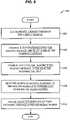
- FIG. 6is a flow chart illustrating a method 600 for dynamically establishing a media channel using channel setup system 502 in an exemplary embodiment of the invention.
- CES 201transmits a request message for a media channel to packet network 210 a .
- Channel setup system 502receives the request message for the media channel and selects one of the response gateways 221 – 223 (assume response gateway 221 ) in emergency services network 220 with which to establish the media channel, in step 604 .
- channel setup system 502 or another systemmay generate the request message to initiate the set up of the media channel.
- Channel setup system 502may include selection logic (not shown) or an algorithm for selecting one of the response gateways 221 – 223 .
- Channel setup system 502then transmits the request message for the media channel to response gateway 221 in step 606 .
- Response gateway 221receives the request message. Responsive to receiving the request message, response gateway 221 responds to the request message to dynamically establish the media channel, in step 608 . CES 201 and response gateway 221 then exchange messages over the media channel in step 612 .
- response gateway 221may transmit a response message to packet network 210 a .
- the response messageindicates an acceptance of the media channel, indicates the acceptance of parameters of the media channel, or otherwise indicates that response gateway 221 is available and capable of handling the media channel.
- Response gateway 221may transmit the response message directly to CES 201 , or may transmit the response message to channel setup system 502 and channel setup system 502 transmits the response message to CES 201 .
- CES 201initiates a process to dynamically establish the media channel.
- Response gateway 221may negotiate parameters of the media channel before transmitting the response message. If response gateway 221 and CES 201 cannot agree on parameters for the media channel, then response gateway 221 transmits a response message indicating a rejection of the media channel. Response gateway 221 may transmit the response message directly to CES 201 or may transmit the response message to CES 201 through channel setup system 502 . If CES 201 receives a response message indicating a rejection of the media channel, then CES 201 may initiate and transmit a new request message to packet network 210 a . If channel setup system 502 receives a response message indicating a rejection of the media channel, then channel setup system 502 selects another one of the response gateways 222 – 223 and transmits the request message to the newly selected resource.
- response gateway 221may initiate a process to dynamically establish the media channel between CES 201 and response gateway 221 .
- CES 201 , channel setup system 502 , and response gateway 221may use Session Initiation Protocol (SIP), H.323, Signaling System No. 7 (SS7), LAPD, Q.921, Q.931, or another comparable protocol or method for dynamically establishing a media channel.
- SIPSession Initiation Protocol
- H.323, Signaling System No. 7 (SS7)Signaling System No. 7
- LAPDLAPD
- Q.921, Q.931Q.921, Q.931, or another comparable protocol or method for dynamically establishing a media channel.
- the request message from CES 201may comprise a SIP Invite message.
- Channel setup system 502 , CES 201 , and/or response gateways 221 – 223are able to tear down the media channel after a time period or responsive to instructions.
- one of the response gateways 221 – 223may initiate the setup of a media channel with CES 201 .
- a response gateway(assume response gateway 223 ) transmits a request message for a media channel to packet network 210 a .
- Channel setup system 502receives the request message and transmits the request message to CES 201 .
- CES 201receives the request message and responds to the request message to dynamically establish the media channel.
- CES 201 and response gateway 223may then exchange messages over the media channel.
- FIG. 7illustrates channel setup system 502 in an exemplary embodiment of the invention.
- Channel setup system 502includes a processor 702 , selection logic 703 , and a data structure 704 .
- Data structure 704includes information on response gateways 221 – 223 of emergency services network 220 , information on routing messages to systems connected to packet network 210 a , and other information and data.
- data structure 704may include information on the capacity or current load of each response gateway 221 – 223 , information on the operational status of each response gateway (e.g., in service/out of service), information on the number of media channels per response gateway 221 – 223 , information on security, information on the location of each response gateway 221 – 223 , information on the data connectivity speed of each response gateway 221 – 223 , information on the type of protocol used by each response gateway 221 – 223 , information on the type of response gateway 221 – 223 , etc.
- Data structure 704may include much more information than that which is described.
- Each response gateway 221 – 223may update channel setup system 502 as to information on that response gateway.
- channel setup system 502receives a request message for a media channel. Responsive to the request message, processor 702 executes selection logic 703 to select one of the response gateways 221 – 223 in emergency services network 220 with which to establish the media channel. Selection logic 703 may identify the availability of each of the response gateways 221 – 223 in making the selection. For instance, in making the selection, selection logic 703 accesses data structure 704 for information on the individual response gateways. If response gateway 222 is at 90% of its capacity and response gateway 221 is a 10% of its capacity, then selection logic 703 may select response gateway 221 . If response gateway 223 has failed or has been taken out of service for maintenance, then selection logic 703 will not select response gateway 223 .
- selection logic 703may select response gateway 221 to balance out the media channels between the response gateways 221 – 223 .
- channel setup system 502transmits the request message for the media channel to the selected response gateway.
- FIG. 8illustrates communication network 200 further including an Service/Name Resolution (SNR) system 800 in an exemplary embodiment of the invention.
- Service/Name Resolution (SNR) system 800is connected to packet network 210 b .
- FIG. 8shows the emergency services in emergency services network 220 as ALI database 831 , Mobile Positioning Center (MPG) 832 , and Emergency Auxiliary Service Provider (EASP) 833 .
- MPGMobile Positioning Center
- EASPEmergency Auxiliary Service Provider
- SNR system 800is configured to communicate with ALI database 831 , MPC 832 , and EASP 833 so that ALI database 831 , MPC 832 , and EASP 833 can register the information that they contain with SNR system 800 .
- SNR system 800stores a directory of the information contained in each of ALI database 831 , MPC 832 , and EASP 833 .
- the directory of informationis indexed by a retrieval key.
- a retrieval keycomprises any indicator, token, or key, such as a telephone number (including a dialed number, Emergency Service Routing Digits (ESRD), Emergency Service Routing Keys (ESRK), or any other string of digits according to the E.164 encoding scheme), a network address (including a Session Initiation Protocol (SIP) address, a MAC address, an IP address, a Universal Resource Identifier, or any other form of identification associated with a communication device), a trunk ID, a social security number, a street address, an employee ID, an email address, and an incident ID.
- a telephone numberincluding a dialed number, Emergency Service Routing Digits (ESRD), Emergency Service Routing Keys (ESRK), or any other string of digits according to the E.164 encoding scheme
- a network addressincluding a Session Initiation Protocol (SIP) address, a MAC address, an IP address, a Universal Resource Identifier, or any other form of identification associated with
- FIG. 9is a flow chart illustrating communications in communication network 200 in an exemplary embodiment of the invention.
- CES 201needs to access information in emergency services network 220 to handle an emergency event.
- CES 201transmits an emergency event message to response gateway 221 over the media channel established between CES 201 and response gateway 221 , in step 902 .
- the emergency event messageincludes a retrieval key.
- response gateway 221initiates an emergency event session corresponding with the retrieval key in step 904 .
- An emergency event sessioncomprises any period of communication between a conforming emergency system and a response gateway over a media channel for a particular retrieval key. Multiple emergency event sessions for multiple retrieval keys may be established over a media channel.
- response gateway 221transmits a query (including the retrieval key) to SNR system 800 in step 908 .
- Response gateway 221queries SNR system 800 to more efficiently obtain information corresponding with the retrieval key from the emergency services.
- the following methodsillustrate ways that response gateway 221 may obtain the information from the emergency services.
- FIG. 10is a flow chart illustrating a method 1000 in an exemplary embodiment of the invention.
- SNR system 800receives the retrieval key from response gateway 221 . Responsive to the retrieval key, SNR system 800 accesses its directory of information for ALI database 831 , MPC 832 , and EASP 833 . SNR system 800 identifies which of ALI database 831 , MPC 832 , and EASP 833 correspond with the retrieval key in step 1004 .
- ALI database 831 , MPC 832 , and/or EASP 833include information associated with the retrieval key or that a subscriber has subscribed to ALI database 831 , MPC 832 , or EASP 833 using the retrieval key.
- SNR system 800then transmits a message to response gateway 221 indicating which of ALI database 831 , MPC 832 , and EASP 833 correspond with the retrieval key in step 1006 .
- SNR system 800identifies that MPC 832 and EASP 833 correspond with the retrieval key.
- response gateway 221transmits queries to MPC 832 and EASP 833 using the retrieval key in step 1008 .
- MPC 832 and EASP 833each receive the query and perform any services corresponding with the retrieval key.
- at least one of MPC 832 and EASP 833transmit information corresponding with the retrieval key to response gateway 221 or CES 201 .
- MPC 832having location information corresponding with the retrieval key, transmits the location information to response gateway 221 .
- EASP 832having medical information corresponding with the retrieval key, transmits the medical information to response gateway 221 .
- FIG. 11is a flow chart illustrating a method 1100 in another exemplary embodiment of the invention.
- SNR system 800receives the retrieval key from response gateway 221 . Responsive to the retrieval key, SNR system 800 accesses its directory of the information for ALI database 831 , MPC 832 , and EASP 833 . SNR system 800 identifies which of ALI database 831 , MPC 832 , and EASP 833 correspond with the retrieval key in step 1104 . Assume that SNR system 800 identifies that MPC 832 and EASP 833 correspond with the retrieval key. SNR system 800 then transmits queries to MPC 832 and EASP 833 using the retrieval key in step 1106 .
- MPC 832 and EASP 833each receive queries and perform any services corresponding with the retrieval key.
- step 1108at least one of MPC 832 and EASP 833 transmit information corresponding with the retrieval key to SNR system 800 .
- MPC 832having location information corresponding with the retrieval key, transmits the location information to SNR system 800 .
- EASP 832having medical information corresponding with the retrieval key, transmits the medical information to SNR system 800 .
- SNR system 800transmits the information to response gateway 221 or CES 201 .
- FIG. 12is a flow chart illustrating a method 1200 in another exemplary embodiment of the invention.
- SNR system 800receives the retrieval key from response gateway 221 . Responsive to the retrieval key, SNR system 800 accesses its directory of the information for ALI database 831 , MPC 832 , and EASP 833 . SNR system 800 identifies which of ALI database 831 , MPC 832 , and EASP 833 correspond with the retrieval key in step 1204 . Assume that SNR system 800 identifies that MPC 832 and EASP 833 correspond with the retrieval key. SNR system 800 then transmits queries to MPC 832 and EASP 833 using the retrieval key in step 1206 .
- the queryincludes an address for response gateway 221 or an instruction to transmit information to response gateway 221 .
- MPC 832 and EASP 833each receive the query and perform any services corresponding with the retrieval key.
- MPC 832 and EASP 833transmit information corresponding with the retrieval key to response gateway 221 .
- MPC 832having location information corresponding with the retrieval key, transmits the location information to response gateway 221 .
- EASP 832having medical information corresponding with the retrieval key, transmits the medical information to response gateway 221 .
- the instruction in the queriesmay also be to transmit information directly to CES 201 .
- response gateway 221transmits the information to CES 201 in step 910 .
- Transmitting the information in this embodimentmeans that response gateway 221 voluntarily transmits information to CES 201 , and is not limited to the request-response model of the prior art.
- response gateway 221when response gateway 221 receives the location information originating from MPC 832 , response gateway 221 transmits the location information to CES 201 .
- response gateway 221when response gateway 221 receives the medical information originating from EASP 833 , response gateway 221 transmits the medical information to CES 201 .
- Response gateway 221does not have to wait for a request message from CES 201 before transmitting the information to CES 201 .
- Response gateway 221may transmit the information at its own volition, but preferably as soon as it is received.
- Response gateway 221may use any compatible transport protocol for transmitting the information, such as TCP/IP, HTTP, XML, and RTP.
- Response gateway 221may transmit other messages to CES 201 .
- response gateway 221may transmit management data, status reports, etc, to CES 201 .
- CES 201 and/or response gateway 221may end the emergency event session when all information and services have been provided for the retrieval key or if CES 201 no longer needs information from response gateway 221 .
- Emergency services network 220uses a new message set for transmitting the information to CES 201 .
- the message set used by emergency services network 220allows either CES 201 or response gateway 221 to initiate the transfer of a message.
- the emergency event sessioncreates a dialog between CES 201 and response gateway 221 so that either one may transmit a message when they have something to provide to the other.
- the prior art communication networkshave a PSAP-ALI interface that uses a request-response model.
- Communication network 200is not limited to the request-response model, as either response gateway 221 or CES 201 may initiate a transfer of a message.
- Response gateway 221 and CES 201have an open dialog during an emergency event session, which was not allowed in the prior art.
- the new message setalso allows response gateway 221 to provide enhanced data types to CES 201 , and vice-versa.
- the PSAP-ALI interfaceonly allowed the ALI database to provide a fixed-length text string to the CES.
- the new message setis flexible and allows response gateway 221 to transmit larger data streams. For instance, response gateway 221 may transmit information in the form of streaming video, streaming audio, graphics data, voice, text data, binary data, executable instructions or scripts, etc.
- communication network 200is advantageously more flexible, expandable, and reliable than prior networks.
- Conforming emergency systemscan communicate with different response gateways by establishing a media channel to interface with the emergency services network.
- the conforming emergency systemsare not reliant on a pair of ALI databases as in the prior art.
- the response gatewaysalso use a larger and more flexible message set to enhance the size and types of data provided to the conforming emergency systems.
- emergency services networksmay use modern technology to provide the best possible emergency services.
Landscapes
- Business, Economics & Management (AREA)
- Engineering & Computer Science (AREA)
- Emergency Management (AREA)
- Signal Processing (AREA)
- Health & Medical Sciences (AREA)
- Environmental & Geological Engineering (AREA)
- Public Health (AREA)
- Computer Networks & Wireless Communication (AREA)
- Marketing (AREA)
- Mobile Radio Communication Systems (AREA)
- Telephonic Communication Services (AREA)
- Data Exchanges In Wide-Area Networks (AREA)
Abstract
Description
Claims (59)
Priority Applications (2)
| Application Number | Priority Date | Filing Date | Title |
|---|---|---|---|
| US10/816,613US7200207B2 (en) | 2004-03-13 | 2004-04-02 | Communication network for providing emergency services |
| PCT/US2005/006537WO2005091907A2 (en) | 2004-03-13 | 2005-02-28 | Communication network for providing emergency services |
Applications Claiming Priority (2)
| Application Number | Priority Date | Filing Date | Title |
|---|---|---|---|
| US55283304P | 2004-03-13 | 2004-03-13 | |
| US10/816,613US7200207B2 (en) | 2004-03-13 | 2004-04-02 | Communication network for providing emergency services |
Publications (2)
| Publication Number | Publication Date |
|---|---|
| US20050201527A1 US20050201527A1 (en) | 2005-09-15 |
| US7200207B2true US7200207B2 (en) | 2007-04-03 |
Family
ID=34922784
Family Applications (1)
| Application Number | Title | Priority Date | Filing Date |
|---|---|---|---|
| US10/816,613Expired - LifetimeUS7200207B2 (en) | 2004-03-13 | 2004-04-02 | Communication network for providing emergency services |
Country Status (2)
| Country | Link |
|---|---|
| US (1) | US7200207B2 (en) |
| WO (1) | WO2005091907A2 (en) |
Cited By (18)
| Publication number | Priority date | Publication date | Assignee | Title |
|---|---|---|---|---|
| US20060224629A1 (en)* | 2005-03-18 | 2006-10-05 | Liveprocess Corporation | Networked emergency management system |
| US20070174093A1 (en)* | 2005-09-14 | 2007-07-26 | Dave Colwell | Method and system for secure and protected electronic patient tracking |
| US20070201622A1 (en)* | 2006-02-28 | 2007-08-30 | Marian Croak | Method and apparatus for providing E911 services for nomadic users |
| US20070297589A1 (en)* | 2005-09-14 | 2007-12-27 | Greischar Patrick J | Method and system for data aggregation for real-time emergency resource management |
| US20080046285A1 (en)* | 2006-08-18 | 2008-02-21 | Greischar Patrick J | Method and system for real-time emergency resource management |
| US20100098062A1 (en)* | 2006-02-28 | 2010-04-22 | Marian Croak | Method and apparatus for providing e911 services via network announcements |
| US20110058659A1 (en)* | 2009-09-10 | 2011-03-10 | Merlino Joseph M | Emergency communications system |
| US20110188411A1 (en)* | 2010-02-02 | 2011-08-04 | Stefano Faccin | System and method for packetized emergency messages |
| US20110189971A1 (en)* | 2010-02-02 | 2011-08-04 | Stefano Faccin | System and method for packetized emergency messages |
| US20110188416A1 (en)* | 2010-02-02 | 2011-08-04 | Stefano Faccin | System and method for packetized emergency messages |
| US20140378082A1 (en)* | 2013-06-25 | 2014-12-25 | Siemens Schweiz Ag | Modality-centric mass notification system |
| US20140376410A1 (en)* | 2013-06-25 | 2014-12-25 | Siemens Schweiz Ag | Incident-centric Mass Notification System |
| US9072074B1 (en) | 2006-12-27 | 2015-06-30 | At&T Intellectual Property Ii, L.P. | Method and apparatus for determining the location of a terminal adaptor |
| US9786154B1 (en)* | 2014-07-21 | 2017-10-10 | State Farm Mutual Automobile Insurance Company | Methods of facilitating emergency assistance |
| US10588004B2 (en) | 2006-05-16 | 2020-03-10 | RedSky Technologies, Inc. | Method and system for locating a network device in an emergency situation |
| US10912056B2 (en) | 2006-05-16 | 2021-02-02 | RedSky Technologies, Inc. | Method and system for locating a network device in an emergency situation including public location information |
| US11089441B2 (en) | 2006-05-16 | 2021-08-10 | RedSky Technologies, Inc. | Method and system for locating a network device in an emergency situation including public location information with device verification |
| US20240236018A1 (en)* | 2023-01-11 | 2024-07-11 | SitNet LLC | Systems and methods for creating situational networks |
Families Citing this family (12)
| Publication number | Priority date | Publication date | Assignee | Title |
|---|---|---|---|---|
| US7483416B2 (en) | 2005-04-01 | 2009-01-27 | Cml Emergency Services Inc. | Internet protocol radio dispatch system and method |
| US7460510B2 (en)* | 2005-04-01 | 2008-12-02 | Cml Emergency Services Inc. | Radio gateway system and method for interfacing a radio system and an IP network |
| US20070003024A1 (en)* | 2005-06-22 | 2007-01-04 | Cml Emergency Services Inc. | Network emergency call taking system and method |
| US7676228B2 (en)* | 2005-09-19 | 2010-03-09 | Plant Equipment Inc. | Radio interoperability system and method |
| US20070153982A1 (en)* | 2006-01-03 | 2007-07-05 | Sony Ericsson Mobile Communications Ab | Method and Apparatus for Routing Emergency Calls in a VoIP System |
| US20070153984A1 (en)* | 2006-01-03 | 2007-07-05 | Sony Ericsson Mobile Communications Ab | Method and Apparatus for Routing Emergency Calls in a VoIP System |
| US20070153983A1 (en)* | 2006-01-03 | 2007-07-05 | Sony Ericsson Mobile Communications Ab | Method and Apparatus for Routing Emergency Calls in a VoIP System |
| US20070153986A1 (en)* | 2006-01-03 | 2007-07-05 | Sony Ericsson Mobile Communications Ab | Method and Apparatus for Routing Emergency Calls in a VoIP System |
| WO2009061399A1 (en)* | 2007-11-05 | 2009-05-14 | Nagaraju Bandaru | Method for crawling, mapping and extracting information associated with a business using heuristic and semantic analysis |
| US20090199115A1 (en)* | 2008-01-31 | 2009-08-06 | Vik Singh | System and method for utilizing tiles in a search results page |
| CA2840489A1 (en)* | 2011-09-30 | 2013-04-04 | Ranganath C. ABEYWEERA | Method, system and apparatus for a communications client program and an associated transfer server for onymous and secure communications |
| US8548911B2 (en)* | 2012-02-09 | 2013-10-01 | Bank Of America Corporation | Devices and methods for disaster-relief support |
Citations (11)
| Publication number | Priority date | Publication date | Assignee | Title |
|---|---|---|---|---|
| US6151385A (en) | 1998-07-07 | 2000-11-21 | 911 Notify.Com, L.L.C. | System for the automatic notification that a 9-1-1 call has occurred |
| US6385302B1 (en) | 2000-02-08 | 2002-05-07 | Lucent Technologies Inc. | System and method for handling special number calls using on-demand answering stations |
| US20020057764A1 (en) | 2000-11-13 | 2002-05-16 | Angelo Salvucci | Real-time incident and response information messaging in a system for the automatic notification that an emergency call has occurred from a wireline or wireless device |
| US6504909B1 (en) | 2000-11-13 | 2003-01-07 | William C. Cook | Reverse registration method in a system for the automatic notification that a call to an emergency service has occurred |
| US20030086539A1 (en) | 2001-11-05 | 2003-05-08 | Mccalmont Patti L | Geographic routing of emergency service call center emergency calls |
| US6567502B2 (en) | 2000-12-19 | 2003-05-20 | Bellsouth Intellectual Property Corporation | Multimedia emergency services |
| US6587545B1 (en) | 2000-03-04 | 2003-07-01 | Lucent Technologies Inc. | System for providing expanded emergency service communication in a telecommunication network |
| US6600812B1 (en)* | 2000-03-07 | 2003-07-29 | Smart911, Inc. | Method and apparatus for providing emergency response information |
| US6678357B2 (en) | 2001-09-26 | 2004-01-13 | Siemens Information And Communication Networks, Inc. | Internet protocol (IP) emergency connections (ITEC) telephony |
| US6680998B1 (en) | 2001-11-19 | 2004-01-20 | Cisco Technology, Inc. | Providing private network information during emergency calls |
| US6707888B1 (en) | 2002-05-06 | 2004-03-16 | Sprint Communications Company, L.P. | Location evaluation for callers that place emergency telephone calls over packet networks |
Family Cites Families (14)
| Publication number | Priority date | Publication date | Assignee | Title |
|---|---|---|---|---|
| DE3374317D1 (en)* | 1982-11-26 | 1987-12-10 | Nippon Kayaku Kk | Process for producing 4'-demethyl-epipodophyllotoxin-beta-d-ethylidene-glucoside and acyl-derivative thereof |
| US4645661A (en)* | 1984-06-29 | 1987-02-24 | St. Jude Children's Research Hospital | Method for alleviating cisplatin-induced nephrotoxicity and dithiocarbamate compounds for effecting same |
| US4745109A (en)* | 1984-08-20 | 1988-05-17 | Washington Research Foundation | Suicide inhibitors of aromatase |
| US5023253A (en)* | 1987-12-21 | 1991-06-11 | University Patents, Inc. | 6-substituted mitomycin analogs |
| IS2334B (en)* | 1992-09-08 | 2008-02-15 | Vertex Pharmaceuticals Inc., (A Massachusetts Corporation) | Aspartyl protease inhibitor of a new class of sulfonamides |
| US5821260A (en)* | 1992-10-30 | 1998-10-13 | Emory University | Treatment for atherosclerosis and other cardiovascular and inflammatory diseases |
| US5686436A (en)* | 1993-05-13 | 1997-11-11 | Hiv Diagnostics, Inc. | Multi-faceted method to repress reproduction of latent viruses in humans and animals |
| US6074643A (en)* | 1993-09-09 | 2000-06-13 | Cli Oncology, Inc. | Site-directed chemotherapy of metastases |
| US6231852B1 (en)* | 1993-11-18 | 2001-05-15 | The Regents Of The University Of California | Method for reducing BCL-2 expressing cells resistance to death |
| US5919816A (en)* | 1994-11-14 | 1999-07-06 | Bionumerik Pharmaceuticals, Inc. | Formulations and methods of reducing toxicity of antineoplastic agents |
| US5698583A (en)* | 1994-11-15 | 1997-12-16 | Crescenti; Ernesto J.V. | Oligoelements and phospholipase A2 immuno-enhancer compositions, preparation thereof, and use thereof |
| US5958918A (en)* | 1995-06-07 | 1999-09-28 | Rhone-Poulenc Rorer Pharmaceuticals Inc. | Substituted (sulfinic acid, sulfonic acid, sulfonylamino or sulfinylamino) N- (aminominomethyl)phenylalkyl!-azaheterocyclylamide compounds |
| US5922761A (en)* | 1996-09-06 | 1999-07-13 | Medinox, Inc. | Methods for in vivo reduction of iron levels and compositions useful therefor |
| US5916910A (en)* | 1997-06-04 | 1999-06-29 | Medinox, Inc. | Conjugates of dithiocarbamates with pharmacologically active agents and uses therefore |
- 2004
- 2004-04-02USUS10/816,613patent/US7200207B2/ennot_activeExpired - Lifetime
- 2005
- 2005-02-28WOPCT/US2005/006537patent/WO2005091907A2/enactiveApplication Filing
Patent Citations (14)
| Publication number | Priority date | Publication date | Assignee | Title |
|---|---|---|---|---|
| US6151385A (en) | 1998-07-07 | 2000-11-21 | 911 Notify.Com, L.L.C. | System for the automatic notification that a 9-1-1 call has occurred |
| US6584307B1 (en) | 2000-02-08 | 2003-06-24 | Lucent Technologies Inc. | System and method for communicating between a special number call answering agency and a mobile action asset |
| US6385302B1 (en) | 2000-02-08 | 2002-05-07 | Lucent Technologies Inc. | System and method for handling special number calls using on-demand answering stations |
| US6415018B1 (en) | 2000-02-08 | 2002-07-02 | Lucent Technologies Inc. | Telecommunication system and method for handling special number calls having geographic sensitivity |
| US6587545B1 (en) | 2000-03-04 | 2003-07-01 | Lucent Technologies Inc. | System for providing expanded emergency service communication in a telecommunication network |
| US6600812B1 (en)* | 2000-03-07 | 2003-07-29 | Smart911, Inc. | Method and apparatus for providing emergency response information |
| US6504909B1 (en) | 2000-11-13 | 2003-01-07 | William C. Cook | Reverse registration method in a system for the automatic notification that a call to an emergency service has occurred |
| US20020057764A1 (en) | 2000-11-13 | 2002-05-16 | Angelo Salvucci | Real-time incident and response information messaging in a system for the automatic notification that an emergency call has occurred from a wireline or wireless device |
| US6567502B2 (en) | 2000-12-19 | 2003-05-20 | Bellsouth Intellectual Property Corporation | Multimedia emergency services |
| US6678357B2 (en) | 2001-09-26 | 2004-01-13 | Siemens Information And Communication Networks, Inc. | Internet protocol (IP) emergency connections (ITEC) telephony |
| US20030086539A1 (en) | 2001-11-05 | 2003-05-08 | Mccalmont Patti L | Geographic routing of emergency service call center emergency calls |
| US6771742B2 (en)* | 2001-11-05 | 2004-08-03 | Intrado Inc. | Geographic routing of emergency service call center emergency calls |
| US6680998B1 (en) | 2001-11-19 | 2004-01-20 | Cisco Technology, Inc. | Providing private network information during emergency calls |
| US6707888B1 (en) | 2002-05-06 | 2004-03-16 | Sprint Communications Company, L.P. | Location evaluation for callers that place emergency telephone calls over packet networks |
Cited By (47)
| Publication number | Priority date | Publication date | Assignee | Title |
|---|---|---|---|---|
| US20060224629A1 (en)* | 2005-03-18 | 2006-10-05 | Liveprocess Corporation | Networked emergency management system |
| US7596608B2 (en)* | 2005-03-18 | 2009-09-29 | Liveprocess Corporation | Networked emergency management system |
| US20100070615A1 (en)* | 2005-03-18 | 2010-03-18 | Liveprocess Corporation | Networked emergency management system |
| US20070174093A1 (en)* | 2005-09-14 | 2007-07-26 | Dave Colwell | Method and system for secure and protected electronic patient tracking |
| US20070297589A1 (en)* | 2005-09-14 | 2007-12-27 | Greischar Patrick J | Method and system for data aggregation for real-time emergency resource management |
| US8428961B2 (en) | 2005-09-14 | 2013-04-23 | Emsystem, Llc | Method and system for data aggregation for real-time emergency resource management |
| US20090018869A1 (en)* | 2005-09-14 | 2009-01-15 | Patrick J Greischar | Method and system for data aggregation for real-time emergency resource management |
| US20070201622A1 (en)* | 2006-02-28 | 2007-08-30 | Marian Croak | Method and apparatus for providing E911 services for nomadic users |
| US20100098062A1 (en)* | 2006-02-28 | 2010-04-22 | Marian Croak | Method and apparatus for providing e911 services via network announcements |
| US8059645B2 (en) | 2006-02-28 | 2011-11-15 | At&T Intellectual Property Ii, L.P. | Method and apparatus for providing E911 services via network announcements |
| US10588004B2 (en) | 2006-05-16 | 2020-03-10 | RedSky Technologies, Inc. | Method and system for locating a network device in an emergency situation |
| US10912056B2 (en) | 2006-05-16 | 2021-02-02 | RedSky Technologies, Inc. | Method and system for locating a network device in an emergency situation including public location information |
| US11089441B2 (en) | 2006-05-16 | 2021-08-10 | RedSky Technologies, Inc. | Method and system for locating a network device in an emergency situation including public location information with device verification |
| US20080046285A1 (en)* | 2006-08-18 | 2008-02-21 | Greischar Patrick J | Method and system for real-time emergency resource management |
| US9072074B1 (en) | 2006-12-27 | 2015-06-30 | At&T Intellectual Property Ii, L.P. | Method and apparatus for determining the location of a terminal adaptor |
| US20110058659A1 (en)* | 2009-09-10 | 2011-03-10 | Merlino Joseph M | Emergency communications system |
| US20110188416A1 (en)* | 2010-02-02 | 2011-08-04 | Stefano Faccin | System and method for packetized emergency messages |
| US20110189971A1 (en)* | 2010-02-02 | 2011-08-04 | Stefano Faccin | System and method for packetized emergency messages |
| US20110188411A1 (en)* | 2010-02-02 | 2011-08-04 | Stefano Faccin | System and method for packetized emergency messages |
| US20140376410A1 (en)* | 2013-06-25 | 2014-12-25 | Siemens Schweiz Ag | Incident-centric Mass Notification System |
| US9641692B2 (en)* | 2013-06-25 | 2017-05-02 | Siemens Schweiz Ag | Incident-centric mass notification system |
| US20140378082A1 (en)* | 2013-06-25 | 2014-12-25 | Siemens Schweiz Ag | Modality-centric mass notification system |
| US10136276B2 (en)* | 2013-06-25 | 2018-11-20 | Siemens Schweiz Ag | Modality-centric mass notification system |
| US10271194B2 (en)* | 2013-06-25 | 2019-04-23 | Siemens Schweiz Ag | Incident-centric mass notification system |
| US10351097B1 (en) | 2014-07-21 | 2019-07-16 | State Farm Mutual Automobile Insurance Company | Methods of theft prevention or mitigation |
| US9786154B1 (en)* | 2014-07-21 | 2017-10-10 | State Farm Mutual Automobile Insurance Company | Methods of facilitating emergency assistance |
| US10723312B1 (en) | 2014-07-21 | 2020-07-28 | State Farm Mutual Automobile Insurance Company | Methods of theft prevention or mitigation |
| US10825326B1 (en) | 2014-07-21 | 2020-11-03 | State Farm Mutual Automobile Insurance Company | Methods of facilitating emergency assistance |
| US10832327B1 (en) | 2014-07-21 | 2020-11-10 | State Farm Mutual Automobile Insurance Company | Methods of providing insurance savings based upon telematics and driving behavior identification |
| US10475127B1 (en) | 2014-07-21 | 2019-11-12 | State Farm Mutual Automobile Insurance Company | Methods of providing insurance savings based upon telematics and insurance incentives |
| US10974693B1 (en) | 2014-07-21 | 2021-04-13 | State Farm Mutual Automobile Insurance Company | Methods of theft prevention or mitigation |
| US10997849B1 (en) | 2014-07-21 | 2021-05-04 | State Farm Mutual Automobile Insurance Company | Methods of facilitating emergency assistance |
| US11030696B1 (en) | 2014-07-21 | 2021-06-08 | State Farm Mutual Automobile Insurance Company | Methods of providing insurance savings based upon telematics and anonymous driver data |
| US11068995B1 (en) | 2014-07-21 | 2021-07-20 | State Farm Mutual Automobile Insurance Company | Methods of reconstructing an accident scene using telematics data |
| US11069221B1 (en) | 2014-07-21 | 2021-07-20 | State Farm Mutual Automobile Insurance Company | Methods of facilitating emergency assistance |
| US10540723B1 (en) | 2014-07-21 | 2020-01-21 | State Farm Mutual Automobile Insurance Company | Methods of providing insurance savings based upon telematics and usage-based insurance |
| US11257163B1 (en) | 2014-07-21 | 2022-02-22 | State Farm Mutual Automobile Insurance Company | Methods of pre-generating insurance claims |
| US11565654B2 (en) | 2014-07-21 | 2023-01-31 | State Farm Mutual Automobile Insurance Company | Methods of providing insurance savings based upon telematics and driving behavior identification |
| US11634102B2 (en) | 2014-07-21 | 2023-04-25 | State Farm Mutual Automobile Insurance Company | Methods of facilitating emergency assistance |
| US11634103B2 (en) | 2014-07-21 | 2023-04-25 | State Farm Mutual Automobile Insurance Company | Methods of facilitating emergency assistance |
| US12365308B2 (en) | 2014-07-21 | 2025-07-22 | State Farm Mutual Automobile Insurance Company | Methods of facilitating emergency assistance |
| US12358463B2 (en) | 2014-07-21 | 2025-07-15 | State Farm Mutual Automobile Insurance Company | Methods of providing insurance savings based upon telematics and driving behavior identification |
| US12151644B2 (en) | 2014-07-21 | 2024-11-26 | State Farm Mutual Automobile Insurance Company | Methods of facilitating emergency assistance |
| US12179695B2 (en) | 2014-07-21 | 2024-12-31 | State Farm Mutual Automobile Insurance Company | Methods of facilitating emergency assistance |
| US12341707B2 (en) | 2023-01-11 | 2025-06-24 | SitNet LLC | Systems and methods for creating situational networks |
| US12113720B2 (en)* | 2023-01-11 | 2024-10-08 | SitNet LLC | Systems and methods for creating situational networks |
| US20240236018A1 (en)* | 2023-01-11 | 2024-07-11 | SitNet LLC | Systems and methods for creating situational networks |
Also Published As
| Publication number | Publication date |
|---|---|
| WO2005091907A2 (en) | 2005-10-06 |
| US20050201527A1 (en) | 2005-09-15 |
| WO2005091907A3 (en) | 2005-11-24 |
Similar Documents
| Publication | Publication Date | Title |
|---|---|---|
| US7200207B2 (en) | Communication network for providing emergency services | |
| US7177398B2 (en) | Bi-directional messaging for an emergency services network | |
| US7123693B2 (en) | Method and apparatus for increasing the reliability of an emergency call communication network | |
| US20050201358A1 (en) | Rotating media channels between resources of an emergency services network and conforming emergency systems | |
| US7315617B2 (en) | Method and system for managing calls of an automatic call distributor | |
| US7630486B2 (en) | Method and system for handling a queued automatic call distributor call | |
| US8520805B2 (en) | Video E911 | |
| US8385881B2 (en) | Solutions for voice over internet protocol (VoIP) 911 location services | |
| US8004402B2 (en) | Method and apparatus for determining a physical location of a customer | |
| US20050201359A1 (en) | Dynamically establishing media channels between resources of an emergency services network and conforming emergency systems | |
| US8149996B2 (en) | Providing routing information to an answering point of an emergency services network | |
| CN103634490A (en) | A gateway for the survivability of an enterprise network using SIP | |
| TW200808026A (en) | Providing an indication of network capabilities to a user for special number calls | |
| US6934380B2 (en) | Method and system for automatic contact distribution utilizing presence detection | |
| EP1381244B1 (en) | System and method for location-based call distribution | |
| WO2009137019A1 (en) | Ingress/egress call module | |
| WO2011020337A1 (en) | Computer telecommunication integration exchanger (ctiex), system and method for channel associated data transmission of agent and automatic service | |
| HK1100605B (en) | Bi-directional messaging for an emergency services network | |
| US11930133B2 (en) | Systems and methods for redirecting an emergency callback to a contact of an emergency caller | |
| KR20090125458A (en) | Call connection providing system and method | |
| CN101213825A (en) | Dynamically establishing media channels between resources of an emergency services network and conforming emergency systems |
Legal Events
| Date | Code | Title | Description |
|---|---|---|---|
| AS | Assignment | Owner name:INTRADO INC., COLORADO Free format text:ASSIGNMENT OF ASSIGNORS INTEREST;ASSIGNORS:MEER, STEPHEN MAR;BRUENING, GREGORY WILFRED;CIESLA, LAWRENCE W.;AND OTHERS;REEL/FRAME:015179/0849 Effective date:20040401 | |
| AS | Assignment | Owner name:INTRADO INC., COLORADO Free format text:RECORD TO CORRECT THE THE CONVEYING PARTIES NAME, PREIVOUSLY RECORDED AT REEL 01579, FRAME 0849.;ASSIGNORS:MEER, STEPHEN MARC;BRUENING, GREGORY WILFRED;CIELSA, LAWRENCE W.;AND OTHERS;REEL/FRAME:016549/0921;SIGNING DATES FROM 20040401 TO 20040402 | |
| AS | Assignment | Owner name:LEHMAN COMMERCIAL PAPER, INC.,NEW YORK Free format text:SECURITY AGREEMENT;ASSIGNORS:INTERCALL, INC;INTRADO INC;WEST CORPORATION;AND OTHERS;REEL/FRAME:018433/0233 Effective date:20061024 Owner name:LEHMAN COMMERCIAL PAPER, INC., NEW YORK Free format text:SECURITY AGREEMENT;ASSIGNORS:INTERCALL, INC;INTRADO INC;WEST CORPORATION;AND OTHERS;REEL/FRAME:018433/0233 Effective date:20061024 | |
| STCF | Information on status: patent grant | Free format text:PATENTED CASE | |
| AS | Assignment | Owner name:WACHOVIA BANK, NATIONAL ASSOCIATION, AS ADMINISTRA Free format text:ASSIGNMENT AND ASSUMPTION OF SECURITY;ASSIGNORS:WEST CORPORATION;COSMOSIS CORPORATION;INTERCALL, INC.;AND OTHERS;REEL/FRAME:023085/0574 Effective date:20090810 | |
| AS | Assignment | Owner name:WACHOVIA BANK, NATIONAL ASSOCIATION, AS ADMINISTRA Free format text:SECURITY AGREEMENT;ASSIGNORS:INTERCALL, INC.;INTRADO, INC.;WEST CORPORATION;AND OTHERS;REEL/FRAME:024244/0216 Effective date:20091028 | |
| FPAY | Fee payment | Year of fee payment:4 | |
| SULP | Surcharge for late payment | ||
| FPAY | Fee payment | Year of fee payment:8 | |
| AS | Assignment | Owner name:WEST SAFETY SERVICES, INC., NEBRASKA Free format text:MERGER AND CHANGE OF NAME;ASSIGNORS:INTRADO INFORMATION SYSTEMS HOLDINGS, INC;INTRADO INC.;INTRADO INC.;REEL/FRAME:038874/0228 Effective date:20160401 | |
| AS | Assignment | Owner name:U.S. BANK NATIONAL ASSOCIATION, MINNESOTA Free format text:SECURITY INTEREST;ASSIGNORS:WEST CORPORATION;WEST INTERACTIVE SERVICES CORPORATION;WEST SAFETY SERVICES, INC.;AND OTHERS;REEL/FRAME:039093/0944 Effective date:20160617 | |
| AS | Assignment | Owner name:CREDIT SUISSE AG, CAYMAN ISLANDS BRANCH, AS COLLAT Free format text:NOTICE OF GRANT OF SECURITY INTEREST IN PATENTS (FIRST LIEN);ASSIGNOR:WEST SAFETY SERVICES, INC.;REEL/FRAME:044217/0259 Effective date:20171010 | |
| AS | Assignment | Owner name:WEST SAFETY SERVICES, INC., NEBRASKA Free format text:RELEASE BY SECURED PARTY;ASSIGNOR:U.S. BANK NATIONAL ASSOCIATION;REEL/FRAME:046046/0547 Effective date:20180430 Owner name:WEST UNIFIED COMMUNICATIONS SERVICES, INC., NEBRAS Free format text:RELEASE BY SECURED PARTY;ASSIGNOR:U.S. BANK NATIONAL ASSOCIATION;REEL/FRAME:046046/0547 Effective date:20180430 Owner name:WEST CORPORATION, NEBRASKA Free format text:RELEASE BY SECURED PARTY;ASSIGNOR:U.S. BANK NATIONAL ASSOCIATION;REEL/FRAME:046046/0547 Effective date:20180430 Owner name:WEST INTERACTIVE SERVICES CORPORATION, NEBRASKA Free format text:RELEASE BY SECURED PARTY;ASSIGNOR:U.S. BANK NATIONAL ASSOCIATION;REEL/FRAME:046046/0547 Effective date:20180430 Owner name:RELIANCE COMMUNICATIONS, LLC, NEBRASKA Free format text:RELEASE BY SECURED PARTY;ASSIGNOR:U.S. BANK NATIONAL ASSOCIATION;REEL/FRAME:046046/0547 Effective date:20180430 | |
| MAFP | Maintenance fee payment | Free format text:PAYMENT OF MAINTENANCE FEE, 12TH YEAR, LARGE ENTITY (ORIGINAL EVENT CODE: M1553); ENTITY STATUS OF PATENT OWNER: LARGE ENTITY Year of fee payment:12 | |
| AS | Assignment | Owner name:STARGATE MANAGEMENT LLC, NEBRASKA Free format text:RELEASE BY SECURED PARTY;ASSIGNOR:WELLS FARGO BANK, NATIONAL ASSOCIATION, AS SUCCESSOR TO WACHOVIA BANK, NATIONAL ASSOCIATION;REEL/FRAME:062249/0385 Effective date:20221103 Owner name:INTRADO INTERNATIONAL, LLC, NEBRASKA Free format text:RELEASE BY SECURED PARTY;ASSIGNOR:WELLS FARGO BANK, NATIONAL ASSOCIATION, AS SUCCESSOR TO WACHOVIA BANK, NATIONAL ASSOCIATION;REEL/FRAME:062249/0385 Effective date:20221103 Owner name:WEST ASSET PURCHASING, LLC, NEBRASKA Free format text:RELEASE BY SECURED PARTY;ASSIGNOR:WELLS FARGO BANK, NATIONAL ASSOCIATION, AS SUCCESSOR TO WACHOVIA BANK, NATIONAL ASSOCIATION;REEL/FRAME:062249/0385 Effective date:20221103 Owner name:THE DEBT DEPOT, LLC, NEBRASKA Free format text:RELEASE BY SECURED PARTY;ASSIGNOR:WELLS FARGO BANK, NATIONAL ASSOCIATION, AS SUCCESSOR TO WACHOVIA BANK, NATIONAL ASSOCIATION;REEL/FRAME:062249/0385 Effective date:20221103 Owner name:BUYDEBTCO, LLC, NEBRASKA Free format text:RELEASE BY SECURED PARTY;ASSIGNOR:WELLS FARGO BANK, NATIONAL ASSOCIATION, AS SUCCESSOR TO WACHOVIA BANK, NATIONAL ASSOCIATION;REEL/FRAME:062249/0385 Effective date:20221103 Owner name:INTERCALL TELECOM VENTURES, LLC, NEBRASKA Free format text:RELEASE BY SECURED PARTY;ASSIGNOR:WELLS FARGO BANK, NATIONAL ASSOCIATION, AS SUCCESSOR TO WACHOVIA BANK, NATIONAL ASSOCIATION;REEL/FRAME:062249/0385 Effective date:20221103 Owner name:ASSET DIRECT MORTGAGE, LLC, NEBRASKA Free format text:RELEASE BY SECURED PARTY;ASSIGNOR:WELLS FARGO BANK, NATIONAL ASSOCIATION, AS SUCCESSOR TO WACHOVIA BANK, NATIONAL ASSOCIATION;REEL/FRAME:062249/0385 Effective date:20221103 Owner name:WEST CUSTOMER MANAGEMENT GROUP, LLC, CALIFORNIA Free format text:RELEASE BY SECURED PARTY;ASSIGNOR:WELLS FARGO BANK, NATIONAL ASSOCIATION, AS SUCCESSOR TO WACHOVIA BANK, NATIONAL ASSOCIATION;REEL/FRAME:062249/0385 Effective date:20221103 Owner name:WEST AT HOME, LLC, CALIFORNIA Free format text:RELEASE BY SECURED PARTY;ASSIGNOR:WELLS FARGO BANK, NATIONAL ASSOCIATION, AS SUCCESSOR TO WACHOVIA BANK, NATIONAL ASSOCIATION;REEL/FRAME:062249/0385 Effective date:20221103 Owner name:WEST FACILITIES, LLC, NEBRASKA Free format text:RELEASE BY SECURED PARTY;ASSIGNOR:WELLS FARGO BANK, NATIONAL ASSOCIATION, AS SUCCESSOR TO WACHOVIA BANK, NATIONAL ASSOCIATION;REEL/FRAME:062249/0385 Effective date:20221103 Owner name:WEST DIRECT, LLC, CALIFORNIA Free format text:RELEASE BY SECURED PARTY;ASSIGNOR:WELLS FARGO BANK, NATIONAL ASSOCIATION, AS SUCCESSOR TO WACHOVIA BANK, NATIONAL ASSOCIATION;REEL/FRAME:062249/0385 Effective date:20221103 Owner name:WEST BUSINESS SERVICES, LLC, CALIFORNIA Free format text:RELEASE BY SECURED PARTY;ASSIGNOR:WELLS FARGO BANK, NATIONAL ASSOCIATION, AS SUCCESSOR TO WACHOVIA BANK, NATIONAL ASSOCIATION;REEL/FRAME:062249/0385 Effective date:20221103 Owner name:WEST RECEIVABLE SERVICES, INC., NEBRASKA Free format text:RELEASE BY SECURED PARTY;ASSIGNOR:WELLS FARGO BANK, NATIONAL ASSOCIATION, AS SUCCESSOR TO WACHOVIA BANK, NATIONAL ASSOCIATION;REEL/FRAME:062249/0385 Effective date:20221103 Owner name:WEST NOTIFICATIONS GROUP, INC., NEBRASKA Free format text:RELEASE BY SECURED PARTY;ASSIGNOR:WELLS FARGO BANK, NATIONAL ASSOCIATION, AS SUCCESSOR TO WACHOVIA BANK, NATIONAL ASSOCIATION;REEL/FRAME:062249/0385 Effective date:20221103 Owner name:NORTHERN CONTACT, INC., CALIFORNIA Free format text:RELEASE BY SECURED PARTY;ASSIGNOR:WELLS FARGO BANK, NATIONAL ASSOCIATION, AS SUCCESSOR TO WACHOVIA BANK, NATIONAL ASSOCIATION;REEL/FRAME:062249/0385 Effective date:20221103 Owner name:WEST INTERNATIONAL CORPORATION, NEBRASKA Free format text:RELEASE BY SECURED PARTY;ASSIGNOR:WELLS FARGO BANK, NATIONAL ASSOCIATION, AS SUCCESSOR TO WACHOVIA BANK, NATIONAL ASSOCIATION;REEL/FRAME:062249/0385 Effective date:20221103 Owner name:WEST INTERACTIVE CORPORATION, NEBRASKA Free format text:RELEASE BY SECURED PARTY;ASSIGNOR:WELLS FARGO BANK, NATIONAL ASSOCIATION, AS SUCCESSOR TO WACHOVIA BANK, NATIONAL ASSOCIATION;REEL/FRAME:062249/0385 Effective date:20221103 Owner name:WEST DIRECT II, INC., CALIFORNIA Free format text:RELEASE BY SECURED PARTY;ASSIGNOR:WELLS FARGO BANK, NATIONAL ASSOCIATION, AS SUCCESSOR TO WACHOVIA BANK, NATIONAL ASSOCIATION;REEL/FRAME:062249/0385 Effective date:20221103 Owner name:WEST ASSET MANAGEMENT, INC., CALIFORNIA Free format text:RELEASE BY SECURED PARTY;ASSIGNOR:WELLS FARGO BANK, NATIONAL ASSOCIATION, AS SUCCESSOR TO WACHOVIA BANK, NATIONAL ASSOCIATION;REEL/FRAME:062249/0385 Effective date:20221103 Owner name:TELEVOX SOFTWARE, INCORPORATED, NEBRASKA Free format text:RELEASE BY SECURED PARTY;ASSIGNOR:WELLS FARGO BANK, NATIONAL ASSOCIATION, AS SUCCESSOR TO WACHOVIA BANK, NATIONAL ASSOCIATION;REEL/FRAME:062249/0385 Effective date:20221103 Owner name:MASYS CORPORATION, CALIFORNIA Free format text:RELEASE BY SECURED PARTY;ASSIGNOR:WELLS FARGO BANK, NATIONAL ASSOCIATION, AS SUCCESSOR TO WACHOVIA BANK, NATIONAL ASSOCIATION;REEL/FRAME:062249/0385 Effective date:20221103 Owner name:POSITRON PUBLIC SAFETY SYSTEMS CORP., NEBRASKA Free format text:RELEASE BY SECURED PARTY;ASSIGNOR:WELLS FARGO BANK, NATIONAL ASSOCIATION, AS SUCCESSOR TO WACHOVIA BANK, NATIONAL ASSOCIATION;REEL/FRAME:062249/0385 Effective date:20221103 Owner name:GEO911, INC., CALIFORNIA Free format text:RELEASE BY SECURED PARTY;ASSIGNOR:WELLS FARGO BANK, NATIONAL ASSOCIATION, AS SUCCESSOR TO WACHOVIA BANK, NATIONAL ASSOCIATION;REEL/FRAME:062249/0385 Effective date:20221103 Owner name:INTRADO COMMAND SYSTEMS, INC., NEBRASKA Free format text:RELEASE BY SECURED PARTY;ASSIGNOR:WELLS FARGO BANK, NATIONAL ASSOCIATION, AS SUCCESSOR TO WACHOVIA BANK, NATIONAL ASSOCIATION;REEL/FRAME:062249/0385 Effective date:20221103 Owner name:INTRADO INFORMATION SYSTEM HOLDINGS, INC., NEBRASKA Free format text:RELEASE BY SECURED PARTY;ASSIGNOR:WELLS FARGO BANK, NATIONAL ASSOCIATION, AS SUCCESSOR TO WACHOVIA BANK, NATIONAL ASSOCIATION;REEL/FRAME:062249/0385 Effective date:20221103 Owner name:INTRADO INC., NEBRASKA Free format text:RELEASE BY SECURED PARTY;ASSIGNOR:WELLS FARGO BANK, NATIONAL ASSOCIATION, AS SUCCESSOR TO WACHOVIA BANK, NATIONAL ASSOCIATION;REEL/FRAME:062249/0385 Effective date:20221103 Owner name:INTRADO COMMUNICATIONS OF VIRGINIA INC., NEBRASKA Free format text:RELEASE BY SECURED PARTY;ASSIGNOR:WELLS FARGO BANK, NATIONAL ASSOCIATION, AS SUCCESSOR TO WACHOVIA BANK, NATIONAL ASSOCIATION;REEL/FRAME:062249/0385 Effective date:20221103 Owner name:INTRADO COMMUNICATIONS INC., NEBRASKA Free format text:RELEASE BY SECURED PARTY;ASSIGNOR:WELLS FARGO BANK, NATIONAL ASSOCIATION, AS SUCCESSOR TO WACHOVIA BANK, NATIONAL ASSOCIATION;REEL/FRAME:062249/0385 Effective date:20221103 Owner name:INTERCALL, INC., NEBRASKA Free format text:RELEASE BY SECURED PARTY;ASSIGNOR:WELLS FARGO BANK, NATIONAL ASSOCIATION, AS SUCCESSOR TO WACHOVIA BANK, NATIONAL ASSOCIATION;REEL/FRAME:062249/0385 Effective date:20221103 Owner name:COSMOSIS CORPORATION, NEBRASKA Free format text:RELEASE BY SECURED PARTY;ASSIGNOR:WELLS FARGO BANK, NATIONAL ASSOCIATION, AS SUCCESSOR TO WACHOVIA BANK, NATIONAL ASSOCIATION;REEL/FRAME:062249/0385 Effective date:20221103 Owner name:WEST CORPORATION, NEBRASKA Free format text:RELEASE BY SECURED PARTY;ASSIGNOR:WELLS FARGO BANK, NATIONAL ASSOCIATION, AS SUCCESSOR TO WACHOVIA BANK, NATIONAL ASSOCIATION;REEL/FRAME:062249/0385 Effective date:20221103 Owner name:WEST NOTIFICATIONS GROUP, INC., NEBRASKA Free format text:RELEASE BY SECURED PARTY;ASSIGNOR:WELLS FARGO BANK, NATIONAL ASSOCIATION, AS SUCCESSOR TO WACHOVIA BANK, NATIONAL ASSOCIATION;REEL/FRAME:062201/0960 Effective date:20221103 Owner name:WEST DIRECT, LLC, CALIFORNIA Free format text:RELEASE BY SECURED PARTY;ASSIGNOR:WELLS FARGO BANK, NATIONAL ASSOCIATION, AS SUCCESSOR TO WACHOVIA BANK, NATIONAL ASSOCIATION;REEL/FRAME:062201/0960 Effective date:20221103 Owner name:WEST CORPORATION, NEBRASKA Free format text:RELEASE BY SECURED PARTY;ASSIGNOR:WELLS FARGO BANK, NATIONAL ASSOCIATION, AS SUCCESSOR TO WACHOVIA BANK, NATIONAL ASSOCIATION;REEL/FRAME:062201/0960 Effective date:20221103 Owner name:INTRADO INC., NEBRASKA Free format text:RELEASE BY SECURED PARTY;ASSIGNOR:WELLS FARGO BANK, NATIONAL ASSOCIATION, AS SUCCESSOR TO WACHOVIA BANK, NATIONAL ASSOCIATION;REEL/FRAME:062201/0960 Effective date:20221103 Owner name:INTERCALL, INC., NEBRASKA Free format text:RELEASE BY SECURED PARTY;ASSIGNOR:WELLS FARGO BANK, NATIONAL ASSOCIATION, AS SUCCESSOR TO WACHOVIA BANK, NATIONAL ASSOCIATION;REEL/FRAME:062201/0960 Effective date:20221103 | |
| AS | Assignment | Owner name:INTRADO LIFE & SAFETY, INC., NEBRASKA Free format text:CHANGE OF NAME;ASSIGNOR:WEST SAFETY SERVICES, INC.;REEL/FRAME:062214/0561 Effective date:20190920 | |
| AS | Assignment | Owner name:ROYAL BANK OF CANADA, AS COLLATERAL AGENT, CANADA Free format text:SECURITY INTEREST;ASSIGNOR:INTRADO LIFE & SAFETY, INC.;REEL/FRAME:062596/0780 Effective date:20230131 Owner name:INTRADO LIFE & SAFETY, INC. (F/K/A WEST SAFETY SERVICES, INC.), NEBRASKA Free format text:RELEASE BY SECURED PARTY;ASSIGNOR:CREDIT SUISSE AG, CAYMAN ISLANDS BRANCH, AS AGENT;REEL/FRAME:062544/0178 Effective date:20230131 |