US7199635B2 - High-frequency switching device and semiconductor - Google Patents
High-frequency switching device and semiconductorDownload PDFInfo
- Publication number
- US7199635B2 US7199635B2US10/864,352US86435204AUS7199635B2US 7199635 B2US7199635 B2US 7199635B2US 86435204 AUS86435204 AUS 86435204AUS 7199635 B2US7199635 B2US 7199635B2
- Authority
- US
- United States
- Prior art keywords
- terminals
- voltage
- frequency
- effect transistors
- resistor elements
- Prior art date
- Legal status (The legal status is an assumption and is not a legal conclusion. Google has not performed a legal analysis and makes no representation as to the accuracy of the status listed.)
- Expired - Fee Related, expires
Links
Images


Classifications
- H—ELECTRICITY
- H03—ELECTRONIC CIRCUITRY
- H03K—PULSE TECHNIQUE
- H03K17/00—Electronic switching or gating, i.e. not by contact-making and –breaking
- H03K17/10—Modifications for increasing the maximum permissible switched voltage
- H03K17/102—Modifications for increasing the maximum permissible switched voltage in field-effect transistor switches
- H—ELECTRICITY
- H03—ELECTRONIC CIRCUITRY
- H03K—PULSE TECHNIQUE
- H03K17/00—Electronic switching or gating, i.e. not by contact-making and –breaking
- H03K17/06—Modifications for ensuring a fully conducting state
- H—ELECTRICITY
- H03—ELECTRONIC CIRCUITRY
- H03K—PULSE TECHNIQUE
- H03K17/00—Electronic switching or gating, i.e. not by contact-making and –breaking
- H03K17/10—Modifications for increasing the maximum permissible switched voltage
- H—ELECTRICITY
- H03—ELECTRONIC CIRCUITRY
- H03K—PULSE TECHNIQUE
- H03K17/00—Electronic switching or gating, i.e. not by contact-making and –breaking
- H03K17/51—Electronic switching or gating, i.e. not by contact-making and –breaking characterised by the components used
- H03K17/56—Electronic switching or gating, i.e. not by contact-making and –breaking characterised by the components used by the use, as active elements, of semiconductor devices
- H03K17/687—Electronic switching or gating, i.e. not by contact-making and –breaking characterised by the components used by the use, as active elements, of semiconductor devices the devices being field-effect transistors
- H03K17/6871—Electronic switching or gating, i.e. not by contact-making and –breaking characterised by the components used by the use, as active elements, of semiconductor devices the devices being field-effect transistors the output circuit comprising more than one controlled field-effect transistor
- H—ELECTRICITY
- H03—ELECTRONIC CIRCUITRY
- H03K—PULSE TECHNIQUE
- H03K17/00—Electronic switching or gating, i.e. not by contact-making and –breaking
- H03K17/51—Electronic switching or gating, i.e. not by contact-making and –breaking characterised by the components used
- H03K17/56—Electronic switching or gating, i.e. not by contact-making and –breaking characterised by the components used by the use, as active elements, of semiconductor devices
- H03K17/687—Electronic switching or gating, i.e. not by contact-making and –breaking characterised by the components used by the use, as active elements, of semiconductor devices the devices being field-effect transistors
- H03K17/693—Switching arrangements with several input- or output-terminals, e.g. multiplexers, distributors
- H—ELECTRICITY
- H03—ELECTRONIC CIRCUITRY
- H03K—PULSE TECHNIQUE
- H03K2217/00—Indexing scheme related to electronic switching or gating, i.e. not by contact-making or -breaking covered by H03K17/00
- H03K2217/0036—Means reducing energy consumption
Definitions
- the present inventionrelates to a high-frequency switching device for carrying out amplification, switching and the like of high-frequency signals in mobile communication apparatuses and the like, and to a semiconductor device obtained by integrating this high-frequency switching device on a semiconductor substrate.
- a resistor elementis connected in parallel between the drain and source of each FET constituting a high-frequency switching circuit section as shown in FIG. 15 (for example, refer to Japanese Laid-open Patent Application 2002-232278 (page 13, FIG. 7).
- reference codes 130 to 137respectively designate depletion-type FETs.
- Reference codes 250 to 257respectively designate resistor elements having a resistance value R 1 .
- Reference codes 260 to 267respectively designate resistor elements having a resistance value R 2 .
- Reference codes 270 and 271respectively designate resistor elements having a resistance value R 3 .
- Reference codes 510 to 512respectively designate high-frequency signal input/output terminals.
- Reference codes 610 and 611respectively designate control terminals.
- Reference codes I 1 and I 2respectively designate currents.
- the FETs 130 to 133are turned ON and the FETs 134 to 137 are turned OFF.
- the path from the high-frequency signal input/output terminal 510 to the high-frequency signal input/output terminal 511can be set in the ON state, and the path from the high-frequency signal input/output terminal 510 to the high-frequency signal input/output terminal 512 can be set in the OFF state.
- a gate forward currentflows from the control terminal 610 to the control terminal 611 via the resistor elements 250 to 253 , the FETs 130 to 133 and the resistor element 270 .
- the resistor elements 250 to 253 , 260 to 263 and 270are required to be set at a resistance value of 50 k ⁇ or more so as not to affect the high-frequency characteristics.
- the DC potential at point Bis about 2.1 V. Since the ON resistance values of the FETs 130 to 133 are respectively about several ⁇ and thus negligibly small, the potentials at points B, A and C are nearly equal. As a result, the reverse bias voltage of the FET 134 in the OFF path is about 2.1 V, nearly equal to the voltage at point B.
- the current 411 flowing in the resistor element 270 having the resistance value R 3is 40 ⁇ A.
- Z 0designates the characteristic impedance of the circuit, generally 50 ⁇ , and it is assumed that its value is also 50 ⁇ in this case.
- a gate reverse currentflows from the control terminal 610 via the resistor element 271 , the FETs 134 to 137 and the resistor elements 254 to 257 .
- the resistance value R 3is required to be set at 300 k ⁇ .
- the potential VD at point Dis 1.5 V on the premise that a current of about 1 ⁇ A usually flows as the gate reverse current (I 2 ), whereby the maximum power Pmax is lowered further.
- the handling poweris apt to be lowered owing to the lowering of the drain-source potential of the FET, and the resistance value R 3 cannot be decreased, whereby there is a problem of resulting in the increase of current consumption.
- Japanese Laid-open Patent Application 2002-232278has proposed a method wherein a capacitor is inserted between the high-frequency signal input/output terminal and the switch circuit section so that they are separated with respect to DC.
- a capacitor formed in a semiconductor processis directly connected to the high-frequency signal input/output terminal, there are problems of significantly degrading ESD withstand voltage (electrostatic discharge withstand voltage) and increasing the area of a semiconductor chip incorporating the capacitor.
- An object of the present inventionis to provide a high-frequency switching device and a semiconductor device capable of handling power larger than that of the prior art.
- Another object of the present inventionis to provide a high-frequency switching device and a semiconductor device also capable of reducing current consumption.
- the present inventionis intended to solve the problems encountered in the above-mentioned prior art.
- a series circuit of a plurality of field-effect transistorsone ends of resistor elements are respectively connected individually to the connection points (source/drain) of the field-effect transistors, and a predetermined voltage is applied to the other ends of the resistor elements.
- the devicecan handle power larger than that of the prior art. Furthermore, the current consumption can be reduced.
- a high-frequency switching device in accordance with a first inventioncomprises a plurality of high-frequency signal input/output terminals through which high-frequency signals are input/output, and a plurality of high-frequency switch circuit sections disposed between the plurality of high-frequency signal input/output terminals.
- Each of the plurality of high-frequency switch circuit sectionscomprises a series connection circuit of a plurality of field-effect transistors. Either a high-level voltage or a low-level voltage is applied to the gate terminals of the plurality of field-effect transistors, whereby ON and OFF states are attained.
- the above-mentioned configurationis common to third, fifth and seventh inventions described later.
- the first terminals of resistor elementsare connected to the intermediate connection points of the plurality of field-effect transistors, and a voltage, having a phase opposite to that of the voltage applied to the gate terminals of the plurality of field-effect transistors to which the first terminals of the resistor elements are connected, is applied to the second terminals of the resistor elements.
- a high-frequency switching device in accordance with a second inventioncomprises a plurality of high-frequency signal input/output terminals through which high-frequency signals are input/output, a plurality of series high-frequency switch circuit sections disposed between the plurality of high-frequency signal input/output terminals, and a plurality of shunt high-frequency switch circuit sections disposed between the plurality of high-frequency signal input/output terminals and ground terminals.
- Each of the plurality of series high-frequency switch circuit sections and each of the plurality of shunt high-frequency switch circuit sectionsrespectively comprise a series connection circuit of a plurality of field-effect transistors.
- Either a high-level voltage or a low-level voltageis applied to the gate terminals of the plurality of field-effect transistors, whereby ON and OFF states are attained.
- the above-mentioned configurationis common to fourth, sixth and eighth inventions described later.
- the first terminals of resistor elementsare connected to the intermediate connection points of the plurality of field-effect transistors, and a voltage, having a phase opposite to that of the voltage applied to the gate terminals of the plurality of field-effect transistors to which the first terminals of the resistor elements are connected, is applied to the second terminals of the resistor elements.
- the potentials at the intermediate connection points of the plurality of field-effect transistorscan be prevented from lowering.
- the power that can be handledcan be increased in comparison with that of the prior art, and the current consumption can be reduced in comparison with that of the prior art.
- the potentials at the intermediate connection points of the plurality of field-effect transistorscan be prevented from lowering, the deterioration of the distortion characteristic and the isolation characteristic owing to the lowering of the potentials at the intermediate connection points of the plurality of field-effect transistors is prevented, and excellent high-frequency characteristics are obtained.
- a high-frequency switching device in accordance with a third inventionhas a basic configuration similar to that of the high-frequency switching device in accordance with the first invention. Furthermore, the third invention differs from the first invention in that the first terminals of resistor elements are connected to the intermediate connection points of the plurality of field-effect transistors, the cathodes of diodes are connected to the second terminals of the resistor elements, and a voltage, having a phase opposite to that of the voltage applied to the gate terminals of the plurality of field-effect transistors to which the first terminals of the resistor elements are connected, is applied to the anodes of the diodes.
- a high-frequency switching device in accordance with a fourth inventionhas a basic configuration similar to that of the high-frequency switching device in accordance with the second invention. Furthermore, the fourth invention differs from the second invention in that the first terminals of resistor elements are connected to the intermediate connection points of the plurality of field-effect transistors, the cathodes of diodes are connected to the second terminals of the resistor elements, and a voltage, having a phase opposite to that of the voltage applied to the gate terminals of the plurality of field-effect transistors to which the first terminals of the resistor elements are connected, is applied to the anodes of the diodes.
- a high-frequency switching device in accordance with a fifth inventionhas a basic configuration similar to that of the high-frequency switching device in accordance with the first invention. Furthermore, in the plurality of high-frequency switch circuit sections, that is, first and second high-frequency switch circuit sections operating reversely with each other, the fifth invention differs from the first invention in that the first terminals of first resistor elements are connected to the intermediate connection points of the first plurality of field-effect transistors constituting the first high-frequency switch circuit section, that the first terminals of second resistor elements are connected to the intermediate connection points of the second plurality of field-effect transistors constituting the second high-frequency switch circuit section, and that the second terminals of the first resistor elements connected to the first high-frequency switch circuit section are connected to the second terminals of the second resistor elements connected to the second high-frequency switch circuit section.
- a high-frequency switching device in accordance with a sixth inventionhas a basic configuration similar to that of the high-frequency switching device in accordance with the second invention. Furthermore, in each of the plurality of series high-frequency switch circuit sections and each of the plurality of shunt high-frequency switch circuit sections, that is, first and second high-frequency switch circuit sections operating reversely with each other, the sixth invention differs from the second invention in that the first terminals of first resistor elements are connected to the intermediate connection points of the first plurality of field-effect transistors constituting the first high-frequency switch circuit section, that the first terminals of second resistor elements are connected to the intermediate connection points of the second plurality of field-effect transistors constituting the second high-frequency switch circuit section, and that the second terminals of the first resistor elements connected to the first high-frequency switch circuit section are connected to the second terminals of the second resistor elements connected to the second high-frequency switch circuit section.
- the potentials at the intermediate connection points of the plurality of field-effect transistorscan be prevented from lowering.
- the power that can be handledcan be increased in comparison with that of the prior art, and the current consumption can be reduced in comparison with that of the prior art.
- the potentials at the intermediate connection points of the plurality of field-effect transistorscan be prevented from lowering, the deterioration of the distortion characteristic and the isolation characteristic owing to the lowering of the potentials at the intermediate connection points of the plurality of field-effect transistors is prevented, and excellent high-frequency characteristics are obtained.
- a high-frequency switching device in accordance with a seventh inventionhas a basic configuration similar to that of the high-frequency switching device in accordance with the first invention. Furthermore, the seventh invention differs from the first invention in that the first terminals of resistor elements are connected to the intermediate connection points of the plurality of field-effect transistors respectively constituting the plurality of high-frequency switch circuit sections, and that the second terminals of the resistor elements are all connected commonly.
- a high-frequency switching device in accordance with an eighth inventionhas a basic configuration similar to that of the high-frequency switching device in accordance with the second invention. Furthermore, the eighth invention differs from the second invention in that the first terminals of resistor elements are connected to the intermediate connection points of the plurality of field-effect transistors respectively constituting the series high-frequency switch circuit sections and the shunt high-frequency switch circuit sections, and that the second terminals of the resistor elements are all connected commonly.
- the potentials at the intermediate connection points of the plurality of field-effect transistorscan be prevented from lowering.
- the power that can be handledcan be increased in comparison with that of the prior art, and the current consumption can be reduced in comparison with that of the prior art.
- the potentials at the intermediate connection points of the plurality of field-effect transistorscan be prevented from lowering, the deterioration of the distortion characteristic and the isolation characteristic owing to the lowering of the potentials at the intermediate connection points of the plurality of field-effect transistors is prevented, and excellent high-frequency characteristics are obtained.
- a high-frequency switching device in accordance with a ninth inventionhas a plurality of high-frequency signal input/output terminals through which high-frequency signals are input/output, first and second control terminals to which voltages, having phases opposite to each other, are applied, and a plurality of high-frequency switch circuit sections disposed between the plurality of high-frequency signal input/output terminals.
- Each of the plurality of high-frequency switch circuit sectionscomprises a series connection circuit of a plurality of field-effect transistors. Either a high-level voltage or a low-level voltage is applied to the gate terminals of the plurality of field-effect transistors through either the first or second control terminal, whereby ON and OFF states are attained.
- the above-mentioned configurationis common to an 11th invention described later.
- the first terminals of first resistor elementsare connected to the intermediate connection points of the plurality of field-effect transistors respectively constituting the plurality of switch circuit sections, the second terminals of the first resistor elements are connected commonly, the anode of a first diode is connected to the first control terminal, the anode of a second diode is connected to the second control terminal, the first terminal of a second resistor element is connected to the cathodes of the first and second diodes, the second terminal of the second resistor element is grounded, and the connection point of the first and second diodes and the first terminal of the second resistor element is connected to the second terminals of the first resistor elements.
- a constant bias voltagecan be applied at all times to the field-effect transistors by using the voltage OR circuit comprising the diodes.
- a high-frequency switching device in accordance with a 10th inventionhas a plurality of high-frequency signal input/output terminals through which high-frequency signals are input/output, first and second control terminals to which voltages, having phases opposite to each other, are applied, a plurality of series high-frequency switch circuit sections disposed between the plurality of high-frequency signal input/output terminals, and a plurality of shunt high-frequency switch circuit sections disposed between the plurality of high-frequency signal input/output terminals and ground terminals.
- Each of the plurality of series high-frequency switch circuit sections and each of the plurality of shunt high-frequency switch circuit sectionsrespectively comprise a series connection circuit of a plurality of field-effect transistors.
- Either a high-level voltage or a low-level voltageis applied to the gate terminals of the plurality of field-effect transistors through either the first or second control terminal, whereby ON and OFF states are attained.
- the above-mentioned configurationis common to a 12th invention described later.
- the first terminals of first resistor elementsare connected to the intermediate connection points of the plurality of field-effect transistors respectively constituting each of the plurality of series high-frequency switch circuit sections and each of the plurality of shunt high-frequency switch circuit sections, the second terminals of the first resistor elements are connected commonly, the anode of a first diode is connected to the first control terminal, the anode of a second diode is connected to the second control terminal, the first terminal of a second resistor element is connected to the cathodes of the first and second diodes, the second terminal of the second resistor element is grounded, and the connection point of the first and second diodes and the first terminal of the second resistor element is connected to the second terminals of the first resistor elements.
- the potentials at the intermediate connection points of the plurality of field-effect transistorscan be prevented from lowering.
- the power that can be handledcan be increased in comparison with that of the prior art, and the current consumption can be reduced in comparison with that of the prior art.
- the potentials at the intermediate connection points of the plurality of field-effect transistorscan be prevented from lowering, the deterioration of the distortion characteristic and the isolation characteristic owing to the lowering of the potentials at the intermediate connection points of the plurality of field-effect transistors is prevented, and excellent high-frequency characteristics are obtained.
- a constant bias voltagecan be applied at all times to the field-effect transistors by using the voltage OR circuit comprising the diodes.
- a high-frequency switching device in accordance with an 11th inventionhas a basic configuration similar to that of the high-frequency switching device in accordance with the ninth invention. Furthermore, the 11th invention differs from the ninth invention in that the first terminals of first resistor elements are connected to the intermediate connection points of the plurality of field-effect transistors respectively constituting the plurality of high-frequency switch circuit sections, that the anode of a first diode is connected to the first control terminal, that the first terminal of a second resistor element is connected to the cathode of the first diode, that the second terminal of the second resistor element is connected to the second control terminal, that the anode of a second diode is connected to the second control terminal, that the first terminal of a third resistor element is connected to the cathode of the second diode, that the second terminal of the third resistor element is connected to the first control terminal, that the cathode of the first diode is connected to the second terminals of the first resistor elements connected to the plurality of field-effect transistor
- a low bias voltagecan be applied to the field-effect transistors being in the ON stage, and a high bias voltage can be applied to the field-effect transistors being in the OFF stage.
- a high-frequency switching device in accordance with a 12th inventionhas a basic configuration similar to that of the high-frequency switching device in accordance with the 10th invention. Furthermore, the 12th invention differs from the 10th invention in that the first terminals of first resistor elements are connected to the intermediate connection points of the plurality of field-effect transistors respectively constituting each of the plurality of series high-frequency switch circuit sections and each of the plurality of shunt high-frequency switch circuit sections, that the anode of a first diode is connected to the first control terminal, that the first terminal of a second resistor element is connected to the cathode of the first diode, that the second terminal of the second resistor element is connected to the second control terminal, that the anode of a second diode is connected to the second control terminal, that the first terminal of a third resistor element is connected to the cathode of the second diode, that the second terminal of the third resistor element is connected to the first control terminal, that the cathode of the first diode is
- the potentials at the intermediate connection points of the plurality of field-effect transistorscan be prevented from lowering.
- the power that can be handledcan be increased in comparison with that of the prior art, and the current consumption can be reduced in comparison with that of the prior art.
- the potentials at the intermediate connection points of the plurality of field-effect transistorscan be prevented from lowering, the deterioration of the distortion characteristic and the isolation characteristic owing to the lowering of the potentials at the intermediate connection points of the plurality of field-effect transistors is prevented, and excellent high-frequency characteristics are obtained.
- a low bias voltagecan be applied to the field-effect transistors being in the ON stage, and a high bias voltage can be applied to the field-effect transistors being in the OFF stage.
- a voltage inversion circuit and first and second control terminals to which the input/output signals of the voltage inversion circuit are appliedare provided, and that either a high-level voltage or a low-level voltage is applied to the gate terminals of the plurality of field-effect transistors from either the first or second control terminal.
- a voltage inversion circuitis provided and that the input/output signals of the voltage inversion circuit are applied to the first and second control terminals, respectively.
- a semiconductor device in accordance with the present inventionis obtained by integrating the high-frequency switching device in accordance with one of the first to 12th inventions on a semiconductor substrate.
- This configurationhas an action and an effect similar to those of the first to 12th inventions.
- the present inventionsince the potentials at the intermediate connection points of the plurality of field-effect transistors can be prevented from lowering, the power that can be handled can be increased in comparison with that of the prior art. Furthermore, the deterioration of the distortion characteristic and the isolation characteristic owing to the lowering of the potentials at the intermediate connection points of the plurality of field-effect transistors is prevented, and excellent high-frequency characteristics are obtained.
- FIG. 1is a circuit diagram showing an equivalent circuit of an SPDT switching device in accordance with Embodiment 1 of the present invention
- FIG. 2is a circuit diagram showing an equivalent circuit of an SPDT switching device in accordance with Embodiment 2 of the present invention
- FIG. 3is a characteristic diagram showing the high-frequency characteristics of the SPDT switching device in accordance with Embodiment 2 of the present invention.
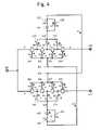
- FIG. 4is a circuit diagram showing an equivalent circuit of an SPDT switching device in accordance with Embodiment 3 of the present invention.
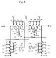
- FIG. 5is a circuit diagram showing an equivalent circuit of an SPDT switching device in accordance with Embodiment 4 of the present invention.
- FIG. 6is a characteristic diagram showing the high-frequency characteristics of the SPDT switching device in accordance with Embodiment 4 of the present invention.
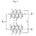
- FIG. 7is a circuit diagram showing an equivalent circuit of an SPDT switching device in accordance with Embodiment 5 of the present invention.
- FIG. 8is a circuit diagram showing an equivalent circuit of an SPDT switching device in accordance with Embodiment 6 of the present invention.
- FIG. 9is a circuit diagram showing an equivalent circuit of an SPDT switching device in accordance with Embodiment 7 of the present invention.
- FIG. 10is a circuit diagram showing an equivalent circuit of an SPDT switching device in accordance with Embodiment 8 of the present invention.
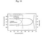
- FIG. 11is a characteristic diagram showing the high-frequency characteristics of the SPDT switching device in accordance with Embodiment 8 of the present invention.
- FIG. 12is a circuit diagram showing an equivalent circuit of an SPDT switching device in accordance with Embodiment 9 of the present invention.
- FIG. 13is a circuit diagram showing an equivalent circuit of an SPDT switching device in accordance with Embodiment 10 of the present invention.
- FIG. 14is a characteristic diagram showing the high-frequency characteristics of the SPDT switching device in accordance with Embodiment 10 of the present invention.
- FIG. 15is a circuit diagram showing an equivalent circuit of the SPBT switching device in accordance with the prior art.
- FIG. 1is a circuit diagram showing the configuration of an SPDT switching device serving as Embodiment 1 of a high-frequency switching device in accordance with the present invention.
- reference codes 101 to 108respectively designate depletion-type FETs.
- Reference codes 201 to 208respectively designate resistor elements having a resistance value R 1 .
- Reference codes 217 to 219 and 221 to 223respectively designate resistor elements having a resistance value R 2 .
- Reference code 501designates a first high-frequency signal input/output terminal.
- Reference code 502designates a second high-frequency signal input/output terminal.
- Reference code 503designates a third high-frequency signal input/output terminal.
- Reference code 601designates a first control terminal.
- Reference code 602designates a second control terminal.
- Reference codes I 1 to I 6respectively designate currents.
- depletion-type FETs having a threshold value of about ⁇ 0.6 Vare used as the FETs 101 to 108 . Therefore, in the above-mentioned voltage conditions, the FETs 101 to 104 to which the high-level voltage is applied are turned ON, and the FETs 105 to 108 to which the low-level voltage is applied are turned OFF.
- code VAdesignates the potential at point A
- code VCdesignates the potential at point C.
- the current I 3is 16 ⁇ A in the above-mentioned conditions. Hence, current consumption can be reduced significantly in comparison with 40 ⁇ A of the prior art.
- the maximum power Pmax at this timeis 2.07 W according to Equation (2).
- this embodimentcan handle up to about 1.5 times the power of the prior art.
- the first terminals of the resistor elements 217 to 219 and 221 to 223are connected to the intermediate connection points (source/drain) of the FETs 101 and 108 .
- a voltagehaving a phase opposite to that of the voltage applied to the gate terminals of the FETs 101 and 108 to which the first terminals of the resistor elements 217 to 219 and 221 to 223 are connected, is applied to the second terminals of the resistor elements 217 to 219 and 221 to 223 , whereby the potentials at the intermediate connection points of the FETs 101 to 108 can be prevented from lowering.
- the power that can be handledcan be increased in comparison with that of the prior art.
- FIG. 2is a circuit diagram showing the configuration of an SPDT switching device serving as Embodiment 2 of a high-frequency switching device in accordance with the present invention.
- FIG. 3is a characteristic diagram showing the high-frequency characteristics of the SPDT switching device shown in FIG. 2 .
- reference codes 101 to 116respectively designate depletion-type FETs.
- Reference codes 201 to 219 , 221 to 223 , 225 to 228 and 230 to 233respectively designate resistor elements.
- Reference code 501designates a first high-frequency signal input/output terminal.
- Reference code 502designates a second high-frequency signal input/output terminal.
- Reference code 503designates a third high-frequency signal input/output terminal.
- Reference code 601designates a first control terminal.
- Reference code 602designates a second control terminal.
- Reference codes 301 and 302respectively designate capacitors.
- Reference codes 701 and 702respectively designate ground terminals.
- the FETs 101 to 104 and the FETs 113 to 116are turned ON, and the FETs 105 to 108 and the FETs 109 to 112 are turned OFF.
- the FETs 105 to 112 of the SPDT switching deviceare not turned ON even when a high power signal is input.
- the FETscan withstand an input power of up to 2.0 W by setting the resistance values at the same values as those of Embodiment 1 of the present invention.
- FIG. 3shows the third harmonic characteristic and isolation characteristic dependent on input power in the SPDT switching device in accordance with Embodiment 2 of the present invention in comparison with those of the SPDT switching device configured in accordance with the prior art.
- the broken linesindicate the characteristics of the prior art, and the solid lines indicate the characteristics of Embodiment 2.
- the third harmonic characteristicbegins to increase when the input power exceeds a certain level.
- the isolation characteristicbegins to decrease when the input power exceeds certain power.
- FIGS. 6 , 11 and 14described later, are similar to FIG. 3 .
- the harmonic characteristic and the isolation characteristicare proportionate to the maximum power that can be handled.
- both the third harmonic characteristic and the isolation characteristicbegin to deteriorate when the input power exceeds 31.5 dBm.
- the characteristicsare excellent when the input power is up to 33 dBm. It is thus understood that Embodiment 2 can handle input power 1.5 dBm larger than that of the configuration of the prior art.
- the current consumptionis 32 ⁇ A. Hence, the current consumption can be reduced significantly in comparison with 80 ⁇ A obtained in the case when a similar circuit is configured on the basis of the prior art.
- the first terminals of the resistor elements 217 to 219 , 221 to 223 , 225 to 228 and 230 to 233are connected to the intermediate connection points of the FETs 101 and 116 .
- the power that can be handledcan be increased in comparison with that of the prior art. Furthermore, since the potentials at the intermediate connection points of the FETs 101 to 116 can be prevented from lowering, the deterioration of the distortion characteristic and the isolation characteristic owing to the lowering of the potentials at the intermediate connection points of the FETs 101 to 116 is prevented, and excellent high-frequency characteristics are obtained.
- the configuration of the present inventionis also similarly applicable to high-frequency switching devices other than SPDT switching devices.
- FIG. 4is a circuit diagram showing the configuration of an SPDT switching device serving as Embodiment 3 of a high-frequency switching device in accordance with the present invention.
- reference codes 101 to 108respectively designate depletion-type FETs.
- Reference codes 201 to 208respectively designate resistor elements having a resistance value R 1 .
- Reference codes 217 to 219respectively designate resistor elements having a resistance value R 2 .
- Reference codes 221 to 223respectively designate resistor elements having a resistance value R 2 .
- Reference codes 235 and 236respectively designate resistor elements having a resistance value R 4 .
- Reference codes 239 and 240respectively designate resistor elements having a resistance value R 3 .
- Reference codes 401 and 402respectively designate diodes.
- Reference code 501designates a first high-frequency signal input/output terminal.
- Reference code 502designates a second high-frequency signal input/output terminal.
- Reference code 503designates a third high-frequency signal input/output terminal.
- Reference code 601designates a first control terminal.
- Reference code 602designates a second control terminal.
- Reference codes 11 , 12 , 14 and 15respectively designate currents.
- Embodiment 3differs from Embodiment 1 in that the diode 401 is inserted between the control terminal 602 and the resistor elements 217 to 219 connected to the intermediate connection points of the FETs and that the diode 402 is inserted between the control terminal 601 and the resistor elements 221 to 223 .
- the resistor element 239is used to control the forward current 12 .
- the resistor element 235is used to prevent the diode 401 from being broken by ESD (electrostatic discharge) from the control terminal 602 .
- ESDelectrostatic discharge
- the forward current I 1flows in the FETs 101 to 104 , whereby the FETs 101 to 104 are turned ON.
- the potential VB at point Bis dominantly determined by the resistance values R 1 and R 3 .
- the potential VB at point Bcan be raised by increasing the resistance value R 3 . As described above, reducing the resistance value R 1 is undesirable because an insertion loss is increased.
- the current I 4can be reduced to a sufficiently small value of 1 ⁇ A or less, whereby the built-in voltage ⁇ B is reduced to about 0.2 V at this time.
- the potential VB at point Bis 2.78 V.
- VD3 ⁇ B ⁇ R 2 ⁇ I 5 (7)
- I 5(4/3) ⁇ I 4
- the maximum power Pmax of the circuit in accordance with Embodiment 3is 2.90 W.
- the circuit configuration of Embodiment 3can handle power 0.9 W higher than that of the circuit configuration of Embodiment 1.
- FIG. 5is a circuit diagram showing the configuration of an SPDT switching device serving as Embodiment 4 of a high-frequency switching device in accordance with the present invention.
- FIG. 6is a characteristic diagram showing the high-frequency characteristics of the SPDT switching device shown in FIG. 5 .
- reference codes 101 to 116respectively designate depletion-type FETs.
- Reference codes 201 to 219 , 221 to 223 , 225 to 228 , 230 to 233 and 235 to 242respectively designate resistor elements.
- Reference codes 403 to 406respectively designate diodes.
- Reference code 501designates a first high-frequency signal input/output terminal.
- Reference code 502designates a second high-frequency signal input/output terminal.
- Reference code 503designates a third high-frequency signal input/output terminal.
- Reference code 601designates a first control terminal.
- Reference code 602designates a second control terminal.
- Reference codes 301 and 302respectively designate capacitors.
- Reference codes 701 and 702respectively designate ground terminals.
- the circuit shown in FIG. 5is an example wherein the circuit of Embodiment 3 shown in FIG. 4 is applied to an SPDT circuit.
- the basic operationis similar to that of the SPDT circuit of Embodiment 2.
- Embodiment 4differs from Embodiment 2 in that a circuit comprising the diode 403 and the resistor elements 235 and 239 is inserted between the control terminal 602 and the resistor elements 217 to 219 connected to the intermediate connection points of the FETs, that a circuit comprising the diode 404 and the resistor elements 236 and 240 is inserted between the control terminal 601 and the resistor elements 221 to 223 , that a circuit comprising the diode 405 and the resistor elements 237 and 241 is inserted between the control terminal 601 and the resistor elements 225 to 228 , and that a circuit comprising the diode 406 and the resistor elements 238 and 242 is inserted between the control terminal 602 and the resistor elements 230 to 233 .
- the action and effect obtained by providing the circuit comprising the diode 403 and the resistor elements 235 and 239 , the circuit comprising the diode 404 and the resistor elements 236 and 240 , the circuit comprising the diode 405 and the resistor elements 237 and 241 and the circuit comprising the diode 406 and the resistor elements 238 and 242are similar to those of Embodiment 3.
- FIG. 6shows the third harmonic characteristic and isolation characteristic dependent on input power in the SPDT circuit in accordance with Embodiment 4 of the present invention in comparison with those of the SPDT switch circuit configured in accordance with the prior art.
- the harmonic characteristic and the isolation characteristicare proportionate to the maximum power that can be handled.
- both the third harmonic characteristic and the isolation characteristicbegin to deteriorate when the input power exceeds 31.5 dBm.
- the characteristicsare excellent when the input power is up to 34.5 dBm. It is thus understood that Embodiment 4 can handle input power 3.0 dBm larger than that of the configuration of the prior art.
- the current consumption of the entire circuitis 5 ⁇ A or less. Hence, excellent characteristics and low current consumption can be attained at the same time.
- the current consumption of the circuit in accordance with Embodiment 4is about several ⁇ A, the current consumption can be lowered significantly in comparison with 80 ⁇ A obtained in the case when a similar circuit is configured on the basis of the prior art.
- the configuration of the present inventionis also similarly applicable to high-frequency switching devices other than SPDT switching devices.
- FIG. 7is a circuit diagram showing the configuration of an SPDT switching device serving as Embodiment 5 of a high-frequency switching device in accordance with the present invention.
- reference codes 101 to 108respectively designate depletion-type FETs.
- Reference codes 201 to 208respectively designate resistor elements having a resistance value R 1 .
- Reference codes 217 to 219 and 221 to 223respectively designate resistor elements having a resistance value R 2 .
- Reference code 501designates a first high-frequency signal input/output terminal.
- Reference code 502designates a second high-frequency signal input/output terminal.
- Reference code 503designates a third high-frequency signal input/output terminal.
- Reference code 601designates a first control terminal.
- Reference code 602designates a second control terminal.
- Reference codes 11 to 13respectively designate currents.
- Embodiment 5differs from Embodiment 1 in that one ends of the resistor elements 217 to 219 , the other ends of which are connected to the intermediate connection points of the FETs 101 to 104 , are directly connected to one ends of the resistor elements 221 to 223 , the other ends of which are connected to the intermediate connection points of the FETs 105 to 108 .
- the first terminals of the resistor elements 217 to 219are connected to the intermediate connection points of the FETs 101 to 104 constituting the first switch circuit section
- the first terminals of the resistor elements 221 to 223are connected to the intermediate connection points of the FETs 105 to 108 constituting the second switch circuit section
- the second terminals of the resistor elements 217 to 219 connected to the first switch circuit sectionare connected to the second terminals of the resistor elements 221 to 223 connected to the second switch circuit section.
- the configuration of the present inventionis also similarly applicable to high-frequency switching devices other than SPDT switching devices.
- FIG. 8is a circuit diagram showing the configuration of an SPDT switching device serving as Embodiment 6 of a high-frequency switching device in accordance with the present invention.
- reference codes 101 to 116respectively designate depletion-type FETs.
- Reference codes 201 to 219 , 221 to 223 , 225 to 228 and 230 to 233respectively designate resistor elements.
- Reference code 501designates a first high-frequency signal input/output terminal.
- Reference code 502designates a second high-frequency signal input/output terminal.
- Reference code 503designates a third high-frequency signal input/output terminal.
- Reference code 601designates a first control terminal.
- Reference code 602designates a second control terminal.
- Reference codes 301 and 302respectively designate capacitors.
- Reference codes 701 and 702respectively designate ground terminals.
- the circuit shown in FIG. 8is an example wherein the circuit of Embodiment 5 shown in FIG. 7 is applied to an SPDT circuit.
- the basic operationis similar to that of the SPDT circuit of Embodiment 2.
- Embodiment 6differs from Embodiment 2 in that one ends of the resistor elements 217 to 219 , the other ends of which are connected to the intermediate connection points of the FETs 101 to 104 , are connected to one ends of the resistor elements 221 to 223 , the other ends of which are connected to the intermediate connection points of the FETs 105 to 108 , and that one ends of the resistor elements 225 to 228 , the other ends of which are connected to the intermediate connection points of the FETs 109 to 112 , are connected one ends of the resistor elements 230 to 233 , the other ends of which are connected to the intermediate connection points of the FETs 113 to 116 .
- the FETs 101 to 108have the same size with a gate width of 4 mm, and the FETs 109 to 116 have the same size with a gate width of 1 mm.
- the current valuesbecome constant, whereby stable characteristics can be obtained.
- this embodimenthas an action and an effect similar to those of Embodiment 5. Furthermore, since the potentials at the intermediate connection points of the plurality of field-effect transistors can be prevented from lowering, the deterioration of the distortion characteristic and the isolation characteristic owing to the lowering of the potentials at the intermediate connection points of the plurality of field-effect transistors is prevented, and excellent high-frequency characteristics are obtained.
- the current consumption of the circuit in accordance with Embodiment 6is 32 ⁇ A, the current consumption can be lowered significantly in comparison with 80 ⁇ A obtained in the case when a similar circuit is configured on the basis of the prior art.
- the configuration of the present inventionis also similarly applicable to high-frequency switching devices other than SPDT switching devices.
- FIG. 9is a circuit diagram showing the configuration of an SPDT switching device serving as Embodiment 7 of a high-frequency switching device in accordance with the present invention.
- reference codes 101 to 116respectively designate depletion-type FETs.
- Reference codes 201 to 219 , 221 to 223 , 225 to 228 and 230 to 233respectively designate resistor elements.
- Reference code 501designates a first high-frequency signal input/output terminal.
- Reference code 502designates a second high-frequency signal input/output terminal.
- Reference code 503designates a third high-frequency signal input/output terminal.
- Reference code 601designates a first control terminal.
- Reference code 602designates a second control terminal.
- Reference codes 301 and 302respectively designate capacitors.
- Reference codes 701 and 702respectively designate ground terminals.
- Embodiment 7differs from Embodiment 6 in that the connection point between one ends of the resistor elements 217 to 219 , the other ends of which are connected to the intermediate connection points of the FETs 101 to 104 and one ends of the resistor elements 221 to 223 , the other ends of which are connected to the intermediate connection points of the FETs 105 to 108 is commonly connected to the connection point between one ends of the resistor elements 225 to 228 , the other ends of which are connected to the intermediate connection points of the FETs 109 to 112 and one ends of the resistor elements 230 to 233 , the other ends of which are connected to the intermediate connection points of the FETs 113 to 116 .
- the first terminals of the resistor elements 217 to 219 , 221 to 223 , 225 to 228 and 230 to 233are connected to the connection points of the FETs 101 to 116 constituting a plurality of switch circuit sections, and the second terminals of the resistor elements 217 to 219 , 221 to 223 , 225 to 228 and 230 to 233 are connected commonly, whereby the potentials at the intermediate connection points of the FETs 101 to 116 can be prevented from lowering. As a result, the power that can be handled can be increased in comparison with that of the prior art.
- the potentials at the intermediate connection points of the FETs 101 to 116can be prevented from lowering, the deterioration of the distortion characteristic and the isolation characteristic owing to the lowering of the potentials at the intermediate connection points of the FETs 101 to 116 is prevented, and excellent high-frequency characteristics are obtained.
- the current consumption of the circuit in accordance with Embodiment 7is about several ⁇ A, the current consumption can be lowered significantly in comparison with 80 ⁇ A obtained in the case when a similar circuit is configured on the basis of the prior art.
- the configuration of the present inventionis also similarly applicable to high-frequency switching devices other than SPDT switching devices.
- FIG. 10is a circuit diagram showing the configuration of an SPDT switching device serving as Embodiment 8 of a high-frequency switching device in accordance with the present invention.
- FIG. 11is a characteristic diagram showing the high-frequency characteristics of the SPDT switching device shown in FIG. 10 .
- reference codes 101 to 116respectively designate depletion-type FETs.
- Reference codes 201 to 233 , 243 , 244 and 245respectively designate resistor elements.
- Reference codes 407 and 408respectively designate diodes.
- Reference code 501designates a first high-frequency signal input/output terminal.
- Reference code 502designates a second high-frequency signal input/output terminal.
- Reference code 503designates a third high-frequency signal input/output terminal.
- Reference code 601designates a first control terminal.
- Reference code 602designates a second control terminal.
- Reference codes 301 and 302respectively designate capacitors.
- Reference codes 701 , 702 and 703respectively designate ground terminals.
- Embodiment 7differs from Embodiment 6 in that the anode of the diode 407 is connected to the first control terminal 601 via the resistor element 243 , that the anode of the diode 408 is connected to the second control terminal 602 via the resistor element 244 , that the cathodes of the diodes 407 and 408 are connected to one end of the resistor element 245 , that the other end of the resistor element 245 is grounded, and that the connection point P of the resistor element 245 and the diodes 407 and 408 is commonly connected to one ends of the resistor elements 217 to 233 , the other ends of which are connected to the intermediate connection points of the FETs 101 to 116 .
- the potential at point Pcan be set at 2.8 V.
- the maximum power Pmax that can be handled by the switching device shown in FIG. 10is 3.10 W, 2.2 times the value of the prior art.
- FIG. 11shows the third harmonic characteristic and isolation characteristic dependent on input power in the SPDT circuit in accordance with Embodiment 8 of the present invention in comparison with those of the SPDT switch circuit of the prior art.
- the harmonic characteristic and the isolation characteristicare proportionate to the maximum power that can be handled.
- both the third harmonic characteristic and the isolation characteristicbegin to deteriorate when the input power exceeds 31.5 dBm.
- the characteristicsare excellent when the input power is up to 34.5 dBm. It is thus understood that Embodiment 8 can handle input power 3.0 dBm larger than that of the prior art.
- the first terminals of the resistor elements 217 to 219 , 221 to 223 , 224 to 228 and 229 to 233are connected to the intermediate connection points of the FETs 101 to 116 constituting the plurality of switch circuit sections, the second terminals of the resistor elements 217 to 219 , 221 to 223 , 224 to 228 and 229 to 233 are connected commonly, the anode of the first diode 407 is connected to the first control terminal 601 , the anode of the second diode 408 is connected to the second control terminal 602 , the first terminal of the resistor element 245 is connected to the cathodes of the first and second diodes 407 and 408 , the second terminal of the resistor element 245 is grounded, and the connection point P of the first terminal of the resistor element 245 and the first and second diodes 407 and 408 is connected to the second terminals of the resistor elements 217 to 219 , 221 to 223 , 224 to 228 and
- the potentials at the intermediate connection points of the FETs 101 to 116can be prevented from lowering.
- the power that can be handledcan be increased in comparison with that of the prior art.
- the potentials at the intermediate connection points of the FETs 101 to 116can be prevented from lowering, the deterioration of the distortion characteristic and the isolation characteristic owing to the lowering of the potentials at the intermediate connection points of the FETs 101 to 116 is prevented, and excellent high-frequency characteristics are obtained.
- a constant bias voltagecan be applied at all times to the FETs 101 to 116 by using the voltage OR circuit comprising the diodes 407 and 408 .
- the current consumption of the circuit in accordance with Embodiment 8is about 40 ⁇ A, the current consumption can be lowered significantly in comparison with 80 ⁇ A obtained in the case when a similar circuit is configured on the basis of the prior art.
- the configuration of the present inventionis also similarly applicable to high-frequency switching devices other than SPDT switching devices.
- circuit sections of the shunt FETs 109 to 116can be omitted.
- FIG. 12is a circuit diagram showing the configuration of an SPDT switching device serving as Embodiment 9 of a high-frequency switching device in accordance with the present invention.
- reference codes 101 to 116respectively designate depletion-type FETs.
- Reference codes 201 to 219 , 221 to 223 , 225 to 228 , 230 to 233 and 246 to 249respectively designate resistor elements.
- Reference codes 409 and 410respectively designate diodes.
- Reference code 501designates a first high-frequency signal input/output terminal.
- Reference code 502designates a second high-frequency signal input/output terminal.
- Reference code 503designates a third high-frequency signal input/output terminal.
- Reference code 601designates a first control terminal.
- Reference code 602designates a second control terminal.
- Reference codes 301 and 302respectively designate capacitors.
- Reference codes 701 and 702respectively designate ground terminals.
- Embodiment 9differs from Embodiment 6 in that the anode of the diode 409 is connected to the first control terminal 601 via the resistor element 246 , that one end of the resistor element 248 is connected to the cathode of the diode 409 , that the control terminal 602 is connected to the other end of the resistor element 248 , that the anode of the diode 410 is connected to the second control terminal 602 via the resistor element 247 , that one end of the resistor element 249 is connected to the cathode of the diode 410 , that the control terminal 601 is connected to the other end of the resistor element 249 , that the cathode of the diode 409 is connected to the resistor elements 217 to 219 and 230 to 233 , and that the cathode of the diode 410 is connected to the resistor elements 221 to 223
- the potential at point Qcan be set at 2.5 V, and the potential at point R can be set at 2.9 V.
- the forward bias voltage of the FETs in the ON statecan be extended and the reverse bias voltage of the FETs in the OFF state can be extended at the same time.
- the maximum power Pmax that can be handled by the switching device shown in FIG. 12is 3.4 W, 2.4 times the value of the prior art.
- the insertion losscan be reduced by 0.1 dB by extending the forward bias voltage of the FETs in the ON state.
- the first terminals of the first resistor elements 217 to 219 , 221 to 223 , 225 to 228 and 230 to 233are connected to the intermediate connection points of the FETs 101 to 116 respectively constituting the series high-frequency switch circuit sections and the shunt high-frequency switch circuit sections, the anode of the first diode 409 is connected to the first control terminal 601 , the cathode of the first diode 409 is connected to the first terminal of the second resistor element 248 , the second terminal of the second resistor element 248 is connected to the second control terminal 602 , the anode of the second diode 410 is connected to the second control terminal 602 , the first terminal of the third resistor element 249 is connected to the cathode of the second diode 410 , the second terminal of the third resistor element 249 is connected to the first control terminal 601 , and the cathode of the first diode 409 is connected to the second terminals of the first resistor elements
- the cathode of the second diode 410is connected to the second terminals of the first resistor elements 221 to 223 and 225 to 228 connected to the FETs 105 to 108 and 109 to 112 , the gates of which are connected to the second control terminal 602 .
- the potentials at the intermediate connection points of the FETs 101 to 116can be prevented from lowering.
- the power that can be handledcan be increased in comparison with that of the prior art.
- the potentials at the intermediate connection points of the FETs 101 to 116can be prevented from lowering, the deterioration of the distortion characteristic and the isolation characteristic owing to the lowering of the potentials at the intermediate connection points of the FETs 101 to 116 is prevented, and excellent high-frequency characteristics are obtained.
- a low bias voltagecan be applied to the FETs being in the ON stage, and a high bias voltage can be applied to the FETs being in the OFF stage.
- the configuration of the present inventionis also similarly applicable to high-frequency switching devices other than SPDT switching devices.
- circuit sections of the shunt FETs 109 to 116can be omitted.
- FIG. 13is a circuit diagram showing the configuration of an SPDT switching device serving as Embodiment 10 of a high-frequency switching device in accordance with the present invention.
- FIG. 14is a characteristic diagram showing the high-frequency characteristics of the SPDT switching device shown in FIG. 13 .
- reference codes 101 to 116respectively designate depletion-type FETs.
- Reference code 120designates an enhancement-type FET.
- Reference codes 201 to 216respectively designate gate-bias resistor elements having a resistance value of 50 k ⁇ .
- Reference codes 217 to 219 , 221 to 223 , 225 to 228 and 230 to 233respectively designate resistor elements for fixing FET voltages, having a resistance value of 100 k ⁇ .
- Reference code 280designates the gate resistor element of a voltage-inverting FET, that is, the enhancement-type FET 120 , having a resistance value of 100 k ⁇ .
- Reference code 281designates the load resistor element of a voltage inversion circuit, having a resistance value of 100 k ⁇ .
- Reference codes 301 and 302respectively designate capacitors having a capacitance value of 10 pF.
- Reference code 501designates a first high-frequency signal input/output terminal.
- Reference code 502designates a second high-frequency signal input/output terminal.
- Reference code 503designates a third high-frequency signal input/output terminal.
- Reference code 607designates a control terminal.
- Reference codes 701 , 702 and 704respectively designate ground terminals.
- Reference code 801designates a power supply terminal.
- Reference code 901designates an SPDT circuit.
- Reference code 902designates a voltage inversion circuit.
- Embodiment 10differs from Embodiment 2 in that the input and output signals of the voltage inversion circuit 902 are simultaneously used as the control signals of the SPDT circuit 901 .
- the control terminal 607to the control terminal 607 , 3 V is applied as a high-level voltage and 0 V is applied as a low-level voltage.
- the voltage applied to the control terminal 607is applied to the gate terminal of the enhancement-type FET 120 via the gate resistor element 280 and is output as a reverse-phase signal from the drain terminal.
- the SPDT circuit 901can be operated by using the input and output voltages of the voltage inversion circuit 902 .
- FIG. 14shows the characteristics obtained in the case when the SPDT circuit 901 in accordance with this embodiment is used, in comparison with the characteristics obtained in the case when the SPDT circuit of the prior art is combined with the voltage inversion circuit.
- the voltage inversion circuit 902comprising an enhancement-type FET
- the output voltagebecomes lower than the power supply voltage owing to a load resistor.
- the SPDT circuit in accordance with the prior artis operated so as to be controlled by a single control voltage from the single control terminal 607 by using the voltage inversion circuit, sufficient voltage is not obtained in many cases.
- excellent high-frequency characteristicscan be obtained by using the configuration of the present invention.
- the configuration of the present inventionis also similarly applicable to high-frequency switching devices other than SPDT switching devices.
- the voltage inversion circuit 902can also be applied to the SPDT switching devices shown in FIGS. 1 , 4 , 5 , 7 , 8 , 9 , 10 and 12 in a way similar to that shown in FIG. 13 .
- a semiconductor device in accordance with the present inventionis obtained by integrating the SPDT switching device in accordance with each of the above-mentioned embodiments on a semiconductor substrate.
Landscapes
- Electronic Switches (AREA)
- Junction Field-Effect Transistors (AREA)
- Transceivers (AREA)
- Amplifiers (AREA)
Abstract
Description
VB=10.4×R3/(R1+4R3) (1)
Pmax=2{n(VH−VL+VT)}2/Z0 (2)
wherein VH designates a high-level voltage applied to the FET, VL designates a Low-level voltage applied to the FET, and VT designates the threshold voltage of the FET. Z0designates the characteristic impedance of the circuit, generally 50 Ω, and it is assumed that its value is also 50 Ω in this case. When VH=2.1 V and VL=0 V are substituted according to the above-mentioned results, and when the maximum power Pmax is calculated in the case when VT=−0.6 V, the maximum power Pmax is 1.40 W. Hence, the effect of the addition of the
VD=3.0−(4×R3+6×R2)I2 (3)
Since this path is also used as an ON path in some cases, the resistance values of the
VB=10.4×R2/(3×R1+4×R2) (4)
VD=3.0−R2×I5 (5)
I3=3×VB/R2
I5=I4×4/3
VB=(3−ΦB){1−R1/(3×R1+4×R2+12×R3)} (6)
wherein ΦB is the built-in voltage of the gate. As clarified by Equation (6), the potential VB at point B is dominantly determined by the resistance values R1 and R3. The potential VB at point B can be raised by increasing the resistance value R3. As described above, reducing the resistance value R1 is undesirable because an insertion loss is increased.
VD=3−ΦB−R2×I5 (7)
I5=(4/3)×I4
When ΦB=0.2 V, I4=1 μA and R2=50 kΩ are substituted into Equation (7) similarly, VD is 2.73 V.
VB=3−R1×I1−ΦB (8)
VD=VB−2×R2×I2 (9)
When R1=50 kΩ, I1=1 μA and ΦB=0.2 V are substituted into Equations (8) and (9), the values of VB=2.75 V and VD=2.62 V are obtained. In addition, Pmax=2.61 W is obtained according to Equation (2). Hence, a value about 1.8 times the value of the prior art is obtained.
Claims (6)
Priority Applications (2)
| Application Number | Priority Date | Filing Date | Title |
|---|---|---|---|
| US11/402,849US7286001B2 (en) | 2003-06-12 | 2006-04-13 | High-frequency switching device and semiconductor device |
| US11/672,415US7636004B2 (en) | 2003-06-12 | 2007-02-07 | High-frequency switching device and semiconductor |
Applications Claiming Priority (2)
| Application Number | Priority Date | Filing Date | Title |
|---|---|---|---|
| JP2003-167615 | 2003-06-12 | ||
| JP2003167615AJP2005006072A (en) | 2003-06-12 | 2003-06-12 | High frequency switch device and semiconductor device |
Related Child Applications (2)
| Application Number | Title | Priority Date | Filing Date |
|---|---|---|---|
| US11/402,849DivisionUS7286001B2 (en) | 2003-06-12 | 2006-04-13 | High-frequency switching device and semiconductor device |
| US11/672,415DivisionUS7636004B2 (en) | 2003-06-12 | 2007-02-07 | High-frequency switching device and semiconductor |
Publications (2)
| Publication Number | Publication Date |
|---|---|
| US20040251952A1 US20040251952A1 (en) | 2004-12-16 |
| US7199635B2true US7199635B2 (en) | 2007-04-03 |
Family
ID=33296870
Family Applications (3)
| Application Number | Title | Priority Date | Filing Date |
|---|---|---|---|
| US10/864,352Expired - Fee RelatedUS7199635B2 (en) | 2003-06-12 | 2004-06-10 | High-frequency switching device and semiconductor |
| US11/402,849Expired - Fee RelatedUS7286001B2 (en) | 2003-06-12 | 2006-04-13 | High-frequency switching device and semiconductor device |
| US11/672,415Expired - Fee RelatedUS7636004B2 (en) | 2003-06-12 | 2007-02-07 | High-frequency switching device and semiconductor |
Family Applications After (2)
| Application Number | Title | Priority Date | Filing Date |
|---|---|---|---|
| US11/402,849Expired - Fee RelatedUS7286001B2 (en) | 2003-06-12 | 2006-04-13 | High-frequency switching device and semiconductor device |
| US11/672,415Expired - Fee RelatedUS7636004B2 (en) | 2003-06-12 | 2007-02-07 | High-frequency switching device and semiconductor |
Country Status (7)
| Country | Link |
|---|---|
| US (3) | US7199635B2 (en) |
| EP (1) | EP1487103B1 (en) |
| JP (1) | JP2005006072A (en) |
| KR (1) | KR20040107426A (en) |
| CN (1) | CN1309166C (en) |
| DE (1) | DE602004017541D1 (en) |
| TW (1) | TWI279082B (en) |
Cited By (55)
| Publication number | Priority date | Publication date | Assignee | Title |
|---|---|---|---|---|
| US20060061434A1 (en)* | 2004-09-17 | 2006-03-23 | Renesas Technology Corp. | Antenna switch circuit and high frequency module having the same |
| US20060194558A1 (en)* | 2005-02-03 | 2006-08-31 | Kelly Dylan J | Canceling harmonics in semiconductor RF switches |
| US20060252394A1 (en)* | 2005-04-21 | 2006-11-09 | Atsushi Suwa | Switching circuit |
| US20060267666A1 (en)* | 2005-05-27 | 2006-11-30 | Nec Electronics Corporation | Semiconductor device |
| US20070139094A1 (en)* | 2003-06-12 | 2007-06-21 | Matsushita Electric Industrial Co., Ltd. | High-frequency switching device and semiconductor |
| US20070159230A1 (en)* | 2006-01-09 | 2007-07-12 | Heston David D | Method and system for high power switching |
| US20070243849A1 (en)* | 2006-04-17 | 2007-10-18 | Skyworks Solutions, Inc. | High-frequency switching device with reduced harmonics |
| US20080076371A1 (en)* | 2005-07-11 | 2008-03-27 | Alexander Dribinsky | Circuit and method for controlling charge injection in radio frequency switches |
| US20080079513A1 (en)* | 2006-10-02 | 2008-04-03 | Skyworks Solutions, Inc. | Switching module with harmonic phase tuning filter |
| US20080079514A1 (en)* | 2006-10-02 | 2008-04-03 | Skyworks Solutions, Inc. | Harmonic phase tuning filter for RF switches |
| US20080265977A1 (en)* | 2007-04-30 | 2008-10-30 | Zeji Gu | High isolation electronic multiple pole multiple throw switch |
| US20080272824A1 (en)* | 2007-05-03 | 2008-11-06 | Chang-Tsung Fu | CMOS RF switch for high-performance radio systems |
| US7459988B1 (en)* | 2006-09-18 | 2008-12-02 | Rf Micro Devices, Inc. | High linearity wide dynamic range radio frequency antenna switch |
| US20090015347A1 (en)* | 2007-07-13 | 2009-01-15 | Skyworks Solutions, Inc. | Switching device with selectable phase shifting modes for reduced intermodulation distortion |
| US20090015508A1 (en)* | 2007-07-13 | 2009-01-15 | Skyworks Solutions, Inc. | Switching device with reduced intermodulation distortion |
| US20090184747A1 (en)* | 2008-01-22 | 2009-07-23 | Nec Electronics Corporation | Switch circuit |
| US20100327948A1 (en)* | 2009-06-29 | 2010-12-30 | Sige Semiconductor Inc. | Switching Circuit |
| US20110002080A1 (en)* | 2008-02-28 | 2011-01-06 | Peregrine Semiconductor Corporation | Method and apparatus for use in digitally tuning a capacitor in an integrated circuit device |
| US20110025408A1 (en)* | 2009-07-30 | 2011-02-03 | Qualcomm Incorporated | Switches with bias resistors for even voltage distribution |
| US20110092179A1 (en)* | 2001-10-10 | 2011-04-21 | Burgener Mark L | Switch Circuit and Method of Switching Radio Frequency Signals |
| US20110165759A1 (en)* | 2007-04-26 | 2011-07-07 | Robert Mark Englekirk | Tuning Capacitance to Enhance FET Stack Voltage Withstand |
| US20110169550A1 (en)* | 2005-07-11 | 2011-07-14 | Brindle Christopher N | Method and Apparatus for Use in Improving Linearity of MOSFETs Using an Accumulated Charge Sink |
| US7982243B1 (en) | 2006-05-05 | 2011-07-19 | Rf Micro Devices, Inc. | Multiple gate transistor architecture providing an accessible inner source-drain node |
| US20110199146A1 (en)* | 2010-02-12 | 2011-08-18 | Winfried Bakalski | High-Frequency Switching Circuit |
| US20120139616A1 (en)* | 2010-12-02 | 2012-06-07 | Richwave Technology Corp. | Double pole double throw switch device |
| US20120262828A1 (en)* | 2011-04-13 | 2012-10-18 | Rf Micro Devices, Inc. | Clamp based esd protection circuits |
| US8330519B2 (en) | 2010-07-09 | 2012-12-11 | Sige Semiconductor Inc. | System and method of transistor switch biasing in a high power semiconductor switch |
| US8559907B2 (en) | 2004-06-23 | 2013-10-15 | Peregrine Semiconductor Corporation | Integrated RF front end with stacked transistor switch |
| US20140062577A1 (en)* | 2012-08-29 | 2014-03-06 | Richwave Technology Corp. | RF Switch with Adaptive Drain and Source Voltage |
| US20140062218A1 (en)* | 2012-08-29 | 2014-03-06 | Richwave Technology Corp. | RF Switch with RF Pathway Charge-Discharge Circuit |
| US8723260B1 (en)* | 2009-03-12 | 2014-05-13 | Rf Micro Devices, Inc. | Semiconductor radio frequency switch with body contact |
| US8742502B2 (en) | 2005-07-11 | 2014-06-03 | Peregrine Semiconductor Corporation | Method and apparatus for use in improving linearity of MOSFETs using an accumulated charge sink-harmonic wrinkle reduction |
| US8829977B2 (en)* | 2012-11-26 | 2014-09-09 | Samsung Electro-Mechanics Co., Ltd. | High frequency switch including diode-connected transistor connected to gate of transistor forming or blocking high frequency signal flow path |
| US8954902B2 (en) | 2005-07-11 | 2015-02-10 | Peregrine Semiconductor Corporation | Method and apparatus improving gate oxide reliability by controlling accumulated charge |
| US20150145587A1 (en)* | 2012-08-09 | 2015-05-28 | Panasonic Intellectual Property Management Co., Ltd. | High frequency semiconductor switch circuit and high frequency radio system including same |
| US9406695B2 (en) | 2013-11-20 | 2016-08-02 | Peregrine Semiconductor Corporation | Circuit and method for improving ESD tolerance and switching speed |
| US9419565B2 (en) | 2013-03-14 | 2016-08-16 | Peregrine Semiconductor Corporation | Hot carrier injection compensation |
| US9425782B2 (en)* | 2013-09-27 | 2016-08-23 | Samsung Electro-Mechanics Co., Ltd. | Radio-frequency switch |
| US20160269018A1 (en)* | 2015-03-13 | 2016-09-15 | Samsung Electro-Mechanics Co., Ltd. | High frequency switch |
| US9590674B2 (en) | 2012-12-14 | 2017-03-07 | Peregrine Semiconductor Corporation | Semiconductor devices with switchable ground-body connection |
| US9627883B2 (en) | 2011-04-13 | 2017-04-18 | Qorvo Us, Inc. | Multiple port RF switch ESD protection using single protection structure |
| US9831857B2 (en) | 2015-03-11 | 2017-11-28 | Peregrine Semiconductor Corporation | Power splitter with programmable output phase shift |
| US20180013420A1 (en)* | 2014-08-29 | 2018-01-11 | Skyworks Solutions, Inc. | Forward isolation in radio-frequency switches using internal regulator |
| US9948281B2 (en) | 2016-09-02 | 2018-04-17 | Peregrine Semiconductor Corporation | Positive logic digitally tunable capacitor |
| US10211830B2 (en) | 2017-04-28 | 2019-02-19 | Qualcomm Incorporated | Shunt termination path |
| US10236872B1 (en) | 2018-03-28 | 2019-03-19 | Psemi Corporation | AC coupling modules for bias ladders |
| US10277205B1 (en) | 2018-06-05 | 2019-04-30 | Samsung Electronics Co., Ltd. | SPDT switch with high linearity |
| US10374641B2 (en) | 2017-01-12 | 2019-08-06 | Samsung Electronics Co., Ltd. | Electronic device having multiband antenna and method for switching in electronic device having multiband antenna |
| US10505530B2 (en) | 2018-03-28 | 2019-12-10 | Psemi Corporation | Positive logic switch with selectable DC blocking circuit |
| US10693231B2 (en) | 2017-09-11 | 2020-06-23 | Qualcomm Incorporated | Transmit/receive switching circuit |
| US10886911B2 (en) | 2018-03-28 | 2021-01-05 | Psemi Corporation | Stacked FET switch bias ladders |
| US11011633B2 (en) | 2005-07-11 | 2021-05-18 | Psemi Corporation | Method and apparatus for use in improving linearity of MOSFETs using an accumulated charge sink-harmonic wrinkle reduction |
| USRE48965E1 (en) | 2005-07-11 | 2022-03-08 | Psemi Corporation | Method and apparatus improving gate oxide reliability by controlling accumulated charge |
| US11476849B2 (en) | 2020-01-06 | 2022-10-18 | Psemi Corporation | High power positive logic switch |
| US20230060745A1 (en)* | 2021-08-16 | 2023-03-02 | Psemi Corporation | Signal Switch with Reduced Parasitic Capacitance |
Families Citing this family (58)
| Publication number | Priority date | Publication date | Assignee | Title |
|---|---|---|---|---|
| JP2005348206A (en)* | 2004-06-04 | 2005-12-15 | Matsushita Electric Ind Co Ltd | High frequency switch circuit and semiconductor device using the same |
| JP2006121187A (en)* | 2004-10-19 | 2006-05-11 | Toshiba Corp | Semiconductor switching circuit |
| GB0612794D0 (en)* | 2006-06-28 | 2006-08-09 | Filtronic Compound Semiconduct | A linear antenna switch arm and a field effect transistor |
| GB2439622B (en)* | 2006-06-28 | 2011-03-30 | Filtronic Compound Semiconductors Ltd | A linear antenna switch arm |
| JP4939857B2 (en)* | 2006-07-04 | 2012-05-30 | パナソニック株式会社 | Switch circuit |
| CN101536327B (en)* | 2006-11-09 | 2013-03-13 | 瑞萨电子株式会社 | Semiconductor integrated circuit, RF module incorporating it, and wireless communication terminal device incorporating it |
| JP4538016B2 (en)* | 2007-03-23 | 2010-09-08 | パナソニック株式会社 | High frequency switch device and semiconductor device |
| US8098088B1 (en)* | 2007-10-16 | 2012-01-17 | Synopsys, Inc. | High-voltage switch using three FETS |
| US20090108911A1 (en) | 2007-10-30 | 2009-04-30 | Rohm Co., Ltd. | Analog switch |
| JP5358476B2 (en)* | 2010-02-15 | 2013-12-04 | ルネサスエレクトロニクス株式会社 | Antenna switch and high-frequency module incorporating it |
| JP5498825B2 (en)* | 2010-03-17 | 2014-05-21 | 新日本無線株式会社 | Semiconductor switch integrated circuit |
| WO2011123640A2 (en)* | 2010-03-31 | 2011-10-06 | Auriga Measurement Systems, LLC | High power radio frequency (rf) switch |
| US8093940B2 (en)* | 2010-04-16 | 2012-01-10 | Sige Semiconductor Inc. | System and method of transistor switch biasing in a high power semiconductor switch |
| US10056895B2 (en) | 2010-04-27 | 2018-08-21 | Qorvo Us, Inc. | High power FET switch |
| US9209784B2 (en) | 2010-04-27 | 2015-12-08 | Rf Micro Devices, Inc. | Switchable capacitive elements for programmable capacitor arrays |
| US8217705B2 (en)* | 2010-05-06 | 2012-07-10 | Micron Technology, Inc. | Voltage switching in a memory device |
| US8179205B2 (en)* | 2010-05-21 | 2012-05-15 | Samsung Electro-Mechanics | Linearization systems and methods for variable attenuators |
| US8275336B2 (en)* | 2010-06-23 | 2012-09-25 | Richwave Technology Corp. | Apparatus and method for digitally controlling capacitance |
| US8228109B2 (en)* | 2010-06-28 | 2012-07-24 | Freescale Semiconductor, Inc. | Transmission gate circuitry for high voltage terminal |
| DE102010040512B4 (en)* | 2010-09-09 | 2016-03-10 | Infineon Technologies Ag | Chip with a high frequency switch assembly and circuitry, method for making a high frequency circuit arrangement |
| WO2012038947A1 (en)* | 2010-09-21 | 2012-03-29 | Dsp Group Ltd. | Rf switch implementation in cmos process |
| US20130252562A1 (en)* | 2010-09-21 | 2013-09-26 | Dsp Group, Ltd. | High power high isolation low current cmos rf switch |
| JP5366911B2 (en)* | 2010-10-18 | 2013-12-11 | パナソニック株式会社 | High frequency switch circuit |
| JP5366914B2 (en)* | 2010-11-25 | 2013-12-11 | パナソニック株式会社 | High frequency semiconductor switch circuit |
| US8368453B2 (en)* | 2011-05-25 | 2013-02-05 | Analog Devices, Inc. | Switch circuits |
| US9124265B2 (en)* | 2011-07-13 | 2015-09-01 | Peregrine Semiconductor Corporation | Method and apparatus for transistor switch isolation |
| KR101175905B1 (en)* | 2011-07-19 | 2012-08-21 | 삼성전기주식회사 | An rf antenna swithch circuit, a high-frequency antenna component and a mobile communication device |
| US8587361B2 (en)* | 2011-09-28 | 2013-11-19 | Infineon Technologies Ag | RF switch circuit including a series connection of a plurality of transistors, RF switch including an RF switch circuit and method for switching RF signals |
| US9543929B2 (en) | 2012-01-06 | 2017-01-10 | Richwave Technology Corp. | Apparatus and method for obtaining power voltage from control signals |
| US9231578B2 (en)* | 2012-01-06 | 2016-01-05 | Richwave Technology Corp. | Apparatus and method for obtaining auxiliary voltage from control signals |
| CN103219974B (en)* | 2012-01-19 | 2016-05-11 | 三星电机株式会社 | HF switch |
| US8729952B2 (en)* | 2012-08-16 | 2014-05-20 | Triquint Semiconductor, Inc. | Switching device with non-negative biasing |
| KR101378866B1 (en)* | 2012-08-23 | 2014-03-27 | 주식회사 하이딥 | Low Power Rf Switch |
| CN103036554B (en)* | 2012-12-11 | 2015-07-08 | 国网浙江省电力公司电力科学研究院 | Switching value signal conversion device and method |
| KR101452072B1 (en)* | 2012-12-21 | 2014-10-16 | 삼성전기주식회사 | Radio frequency switch circuit |
| JP5938357B2 (en)* | 2013-02-26 | 2016-06-22 | 株式会社東芝 | Semiconductor switch circuit |
| US20140253217A1 (en)* | 2013-03-06 | 2014-09-11 | International Rectifier Corporation | RF Switch Gate Control |
| US8994448B2 (en)* | 2013-03-29 | 2015-03-31 | Peregrine Semiconductor Corporation | Systems and methods for generation of internal chip supply bias from high voltage control line inputs |
| TWI514761B (en)* | 2013-06-17 | 2015-12-21 | Realtek Semiconductor Corp | Semiconductor switch |
| CN104242881A (en)* | 2013-06-24 | 2014-12-24 | 瑞昱半导体股份有限公司 | Semiconductor switch |
| JP2015076839A (en)* | 2013-10-11 | 2015-04-20 | 株式会社東芝 | Shunt switch |
| KR101630019B1 (en)* | 2013-11-13 | 2016-06-13 | 삼성전기주식회사 | (Lateral Double diffused MOS RF Switch |
| US20150171860A1 (en)* | 2013-11-13 | 2015-06-18 | Skyworks Solutions, Inc. | Circuits and methods for improved quality factor in a stack of transistors |
| US10270438B2 (en)* | 2014-12-12 | 2019-04-23 | Fairchild Semiconductor Corporation | Switch device with switch circuits that provide high voltage surge protection |
| KR102041655B1 (en)* | 2015-01-07 | 2019-11-07 | 삼성전기주식회사 | High frequency switch |
| JP2016174240A (en)* | 2015-03-16 | 2016-09-29 | 株式会社東芝 | Semiconductor switch |
| CN106160717B (en) | 2015-04-03 | 2020-08-18 | 恩智浦美国有限公司 | Transmission gate circuit |
| CN110419163B (en)* | 2017-03-22 | 2023-12-01 | 索尼半导体解决方案公司 | Semiconductor device and module |
| US10250251B1 (en)* | 2018-02-07 | 2019-04-02 | Infineon Technologies Ag | RF sensor in stacked transistors |
| TWI676366B (en) | 2018-08-10 | 2019-11-01 | 立積電子股份有限公司 | Radio frequency device and voltage generating circuit thereof |
| US20200243484A1 (en)* | 2019-01-30 | 2020-07-30 | Avago Technologies International Sales Pte. Limited | Radio frequency (rf) switch device including rf switch integrated circuit (ic) divided between sides of pcb |
| US10784862B1 (en)* | 2019-09-10 | 2020-09-22 | Nxp Usa, Inc. | High speed switching radio frequency switches |
| TWI734221B (en) | 2019-10-16 | 2021-07-21 | 立積電子股份有限公司 | Radio frequency apparatus and voltage generating device thereof |
| CN112688712B (en) | 2019-10-17 | 2022-07-19 | 立积电子股份有限公司 | Radio frequency device and its voltage generating device |
| JP7425623B2 (en)* | 2020-02-18 | 2024-01-31 | 日清紡マイクロデバイス株式会社 | high frequency switch circuit |
| TWI819264B (en) | 2020-12-25 | 2023-10-21 | 立積電子股份有限公司 | Radio frequency device and voltage generation and harmonic suppressor thereof |
| JP7674897B2 (en)* | 2021-04-23 | 2025-05-12 | 日清紡マイクロデバイス株式会社 | Semiconductor Switch Circuit |
| CN113538882B (en)* | 2021-07-16 | 2022-12-13 | 上海爻火微电子有限公司 | Signal transmission circuit and electronic equipment |
Citations (33)
| Publication number | Priority date | Publication date | Assignee | Title |
|---|---|---|---|---|
| JPS63238716A (en) | 1986-11-14 | 1988-10-04 | Nec Corp | Switching circuit |
| US4929855A (en)* | 1988-12-09 | 1990-05-29 | Grumman Corporation | High frequency switching device |
| JPH0685641A (en) | 1992-08-31 | 1994-03-25 | Mitsubishi Electric Corp | Microwave switch |
| US5350957A (en)* | 1989-10-20 | 1994-09-27 | Texas Instrument Incorporated | Electronic switch controlled by plural inputs |
| JPH08204528A (en) | 1995-01-23 | 1996-08-09 | Sony Corp | Switch circuit and composite switch circuit |
| JPH08213893A (en) | 1995-02-02 | 1996-08-20 | Toshiba Microelectron Corp | Semiconductor integrated circuit |
| JPH08228138A (en) | 1994-12-16 | 1996-09-03 | Matsushita Electron Corp | Semiconductor integrated circuit |
| JPH08293776A (en) | 1995-04-24 | 1996-11-05 | Sony Corp | Semiconductor integrated circuit device |
| JPH10126176A (en) | 1996-10-15 | 1998-05-15 | Sony Corp | Transmission circuit device |
| US5777530A (en)* | 1996-01-31 | 1998-07-07 | Matsushita Electric Industrial Co., Ltd. | Switch attenuator |
| JPH10215128A (en) | 1997-01-30 | 1998-08-11 | Sony Corp | Transmission circuit |
| EP0903855A1 (en) | 1997-02-24 | 1999-03-24 | Sanyo Electric Co., Ltd. | High frequency switching device |
| US5903178A (en) | 1994-12-16 | 1999-05-11 | Matsushita Electronics Corporation | Semiconductor integrated circuit |
| JPH11150464A (en) | 1997-11-17 | 1999-06-02 | Nec Corp | Semiconductor switch circuit, control method for the circuit and attenuator circuit |
| US5917362A (en) | 1996-01-29 | 1999-06-29 | Sony Corporation | Switching circuit |
| JP2000223902A (en) | 1999-02-03 | 2000-08-11 | Sanyo Electric Co Ltd | Switch circuit device |
| JP2000277703A (en) | 1999-03-25 | 2000-10-06 | Sanyo Electric Co Ltd | Switch circuit device |
| US6218890B1 (en) | 1998-07-14 | 2001-04-17 | Sanyo Electric Co., Ltd. | Switching circuit device and semiconductor device |
| US20010040479A1 (en) | 2000-03-03 | 2001-11-15 | Shuyun Zhang | Electronic switch |
| JP2002232278A (en) | 2001-02-01 | 2002-08-16 | Nec Corp | High frequency switch circuit |
| US6489865B1 (en)* | 1999-11-12 | 2002-12-03 | Murata Manufacturing Co., Ltd. | Strip-line filter, duplexer, filter device, communication device, and method of adjusting characteristic of strip-line filter |
| JP2003086767A (en) | 2001-09-14 | 2003-03-20 | Matsushita Electric Ind Co Ltd | Semiconductor device |
| US6642578B1 (en)* | 2002-07-22 | 2003-11-04 | Anadigics, Inc. | Linearity radio frequency switch with low control voltage |
| US6804502B2 (en)* | 2001-10-10 | 2004-10-12 | Peregrine Semiconductor Corporation | Switch circuit and method of switching radio frequency signals |
| US6803680B2 (en)* | 2002-09-13 | 2004-10-12 | Mia-Com, Inc. | Apparatus, methods, and articles of manufacture for a switch having sharpened control voltage |
| US20040207454A1 (en)* | 2003-04-16 | 2004-10-21 | Matsushita Electric Industrial Co., Ltd. | High Frequency switch circuit |
| US20040235549A1 (en)* | 2003-05-21 | 2004-11-25 | Wayne Struble | Individually biased transistor high frequency switch |
| US20050014473A1 (en)* | 2003-07-16 | 2005-01-20 | Yibing Zhao | High power, high linearity and low insertion loss single pole double throw trasmitter/receiver switch |
| US6853235B2 (en)* | 2002-04-26 | 2005-02-08 | Matsushita Electric Industrial Co., Ltd. | High frequency switch, amplifying circuit, and mobile communication terminal |
| US20050047038A1 (en)* | 2003-08-27 | 2005-03-03 | Akishige Nakajima | Electric component for communication device and semiconductor device for switching transmission and reception |
| US20050179506A1 (en)* | 2002-05-17 | 2005-08-18 | Yuji Takahashi | High frequency switch circuit |
| US6978122B2 (en)* | 2001-05-25 | 2005-12-20 | Kabushiki Kaisha Toshiba | High-frequency switching device incorporating an inverter circuit |
| US20060001473A1 (en)* | 2004-06-30 | 2006-01-05 | Matsushita Electric Industrial Co., Ltd. | High frequency switching circuit device |
Family Cites Families (6)
| Publication number | Priority date | Publication date | Assignee | Title |
|---|---|---|---|---|
| JPH08204530A (en)* | 1995-01-23 | 1996-08-09 | Sony Corp | Switch circuit |
| EP1223634A3 (en)* | 2000-12-26 | 2003-08-13 | Matsushita Electric Industrial Co., Ltd. | High-frequency switch, laminated high-frequency switch, high-frequency radio unit, and high-frequency switching method |
| TWI252582B (en)* | 2001-02-27 | 2006-04-01 | Sanyo Electric Co | Switch circuit device |
| US6489856B1 (en)* | 2001-09-17 | 2002-12-03 | Tyco Electronics Corporation | Digital attenuator with combined bits |
| JP2005006072A (en)* | 2003-06-12 | 2005-01-06 | Matsushita Electric Ind Co Ltd | High frequency switch device and semiconductor device |
| JP2007110469A (en)* | 2005-10-14 | 2007-04-26 | Matsushita Electric Ind Co Ltd | High frequency switch device |
- 2003
- 2003-06-12JPJP2003167615Apatent/JP2005006072A/enactivePending
- 2004
- 2004-06-08TWTW093116367Apatent/TWI279082B/ennot_activeIP Right Cessation
- 2004-06-10USUS10/864,352patent/US7199635B2/ennot_activeExpired - Fee Related
- 2004-06-11KRKR1020040043211Apatent/KR20040107426A/ennot_activeWithdrawn
- 2004-06-11CNCNB2004100490543Apatent/CN1309166C/ennot_activeExpired - Fee Related
- 2004-06-11EPEP04013776Apatent/EP1487103B1/ennot_activeExpired - Lifetime
- 2004-06-11DEDE602004017541Tpatent/DE602004017541D1/ennot_activeExpired - Fee Related
- 2006
- 2006-04-13USUS11/402,849patent/US7286001B2/ennot_activeExpired - Fee Related
- 2007
- 2007-02-07USUS11/672,415patent/US7636004B2/ennot_activeExpired - Fee Related
Patent Citations (38)
| Publication number | Priority date | Publication date | Assignee | Title |
|---|---|---|---|---|
| US4810911A (en) | 1986-11-14 | 1989-03-07 | Nec Corp | FET switch circuit having small insertion loss and exhibiting stable operation |
| JPS63238716A (en) | 1986-11-14 | 1988-10-04 | Nec Corp | Switching circuit |
| US4929855A (en)* | 1988-12-09 | 1990-05-29 | Grumman Corporation | High frequency switching device |
| US5350957A (en)* | 1989-10-20 | 1994-09-27 | Texas Instrument Incorporated | Electronic switch controlled by plural inputs |
| JPH0685641A (en) | 1992-08-31 | 1994-03-25 | Mitsubishi Electric Corp | Microwave switch |
| US5903178A (en) | 1994-12-16 | 1999-05-11 | Matsushita Electronics Corporation | Semiconductor integrated circuit |
| JPH08228138A (en) | 1994-12-16 | 1996-09-03 | Matsushita Electron Corp | Semiconductor integrated circuit |
| JPH08204528A (en) | 1995-01-23 | 1996-08-09 | Sony Corp | Switch circuit and composite switch circuit |
| US5717356A (en) | 1995-01-23 | 1998-02-10 | Sony Corporation | Low insertion loss switch |
| JPH08213893A (en) | 1995-02-02 | 1996-08-20 | Toshiba Microelectron Corp | Semiconductor integrated circuit |
| JPH08293776A (en) | 1995-04-24 | 1996-11-05 | Sony Corp | Semiconductor integrated circuit device |
| US5731607A (en) | 1995-04-24 | 1998-03-24 | Sony Corporation | Semiconductor integrated circuit device |
| US5917362A (en) | 1996-01-29 | 1999-06-29 | Sony Corporation | Switching circuit |
| US5777530A (en)* | 1996-01-31 | 1998-07-07 | Matsushita Electric Industrial Co., Ltd. | Switch attenuator |
| JPH10126176A (en) | 1996-10-15 | 1998-05-15 | Sony Corp | Transmission circuit device |
| JPH10215128A (en) | 1997-01-30 | 1998-08-11 | Sony Corp | Transmission circuit |
| EP0903855A1 (en) | 1997-02-24 | 1999-03-24 | Sanyo Electric Co., Ltd. | High frequency switching device |
| JPH11150464A (en) | 1997-11-17 | 1999-06-02 | Nec Corp | Semiconductor switch circuit, control method for the circuit and attenuator circuit |
| US6218890B1 (en) | 1998-07-14 | 2001-04-17 | Sanyo Electric Co., Ltd. | Switching circuit device and semiconductor device |
| JP2000223902A (en) | 1999-02-03 | 2000-08-11 | Sanyo Electric Co Ltd | Switch circuit device |
| JP2000277703A (en) | 1999-03-25 | 2000-10-06 | Sanyo Electric Co Ltd | Switch circuit device |
| US6489865B1 (en)* | 1999-11-12 | 2002-12-03 | Murata Manufacturing Co., Ltd. | Strip-line filter, duplexer, filter device, communication device, and method of adjusting characteristic of strip-line filter |
| US20010040479A1 (en) | 2000-03-03 | 2001-11-15 | Shuyun Zhang | Electronic switch |
| JP2002232278A (en) | 2001-02-01 | 2002-08-16 | Nec Corp | High frequency switch circuit |
| US6978122B2 (en)* | 2001-05-25 | 2005-12-20 | Kabushiki Kaisha Toshiba | High-frequency switching device incorporating an inverter circuit |
| JP2003086767A (en) | 2001-09-14 | 2003-03-20 | Matsushita Electric Ind Co Ltd | Semiconductor device |
| US7012285B2 (en) | 2001-09-14 | 2006-03-14 | Matsushita Electric Industrial Co., Ltd. | Semiconductor device |
| US20050017789A1 (en)* | 2001-10-10 | 2005-01-27 | Burgener Mark L. | Switch circuit and method of switching radio frequency signals |
| US6804502B2 (en)* | 2001-10-10 | 2004-10-12 | Peregrine Semiconductor Corporation | Switch circuit and method of switching radio frequency signals |
| US6853235B2 (en)* | 2002-04-26 | 2005-02-08 | Matsushita Electric Industrial Co., Ltd. | High frequency switch, amplifying circuit, and mobile communication terminal |
| US20050179506A1 (en)* | 2002-05-17 | 2005-08-18 | Yuji Takahashi | High frequency switch circuit |
| US6642578B1 (en)* | 2002-07-22 | 2003-11-04 | Anadigics, Inc. | Linearity radio frequency switch with low control voltage |
| US6803680B2 (en)* | 2002-09-13 | 2004-10-12 | Mia-Com, Inc. | Apparatus, methods, and articles of manufacture for a switch having sharpened control voltage |
| US20040207454A1 (en)* | 2003-04-16 | 2004-10-21 | Matsushita Electric Industrial Co., Ltd. | High Frequency switch circuit |
| US20040235549A1 (en)* | 2003-05-21 | 2004-11-25 | Wayne Struble | Individually biased transistor high frequency switch |
| US20050014473A1 (en)* | 2003-07-16 | 2005-01-20 | Yibing Zhao | High power, high linearity and low insertion loss single pole double throw trasmitter/receiver switch |
| US20050047038A1 (en)* | 2003-08-27 | 2005-03-03 | Akishige Nakajima | Electric component for communication device and semiconductor device for switching transmission and reception |
| US20060001473A1 (en)* | 2004-06-30 | 2006-01-05 | Matsushita Electric Industrial Co., Ltd. | High frequency switching circuit device |
Non-Patent Citations (2)
| Title |
|---|
| European Search Report dated Mar. 16, 2006. |
| Japanese Office Action dated Mar. 1, 2006 with English translation. |
Cited By (123)
| Publication number | Priority date | Publication date | Assignee | Title |
|---|---|---|---|---|
| US10812068B2 (en) | 2001-10-10 | 2020-10-20 | Psemi Corporation | Switch circuit and method of switching radio frequency signals |
| US20110092179A1 (en)* | 2001-10-10 | 2011-04-21 | Burgener Mark L | Switch Circuit and Method of Switching Radio Frequency Signals |
| US10797694B2 (en) | 2001-10-10 | 2020-10-06 | Psemi Corporation | Switch circuit and method of switching radio frequency signals |
| US8583111B2 (en) | 2001-10-10 | 2013-11-12 | Peregrine Semiconductor Corporation | Switch circuit and method of switching radio frequency signals |
| US9225378B2 (en) | 2001-10-10 | 2015-12-29 | Peregrine Semiconductor Corpopration | Switch circuit and method of switching radio frequency signals |
| US7636004B2 (en)* | 2003-06-12 | 2009-12-22 | Panasonic Corporation | High-frequency switching device and semiconductor |
| US20070139094A1 (en)* | 2003-06-12 | 2007-06-21 | Matsushita Electric Industrial Co., Ltd. | High-frequency switching device and semiconductor |
| US11070244B2 (en) | 2004-06-23 | 2021-07-20 | Psemi Corporation | Integrated RF front end with stacked transistor switch |
| US9680416B2 (en) | 2004-06-23 | 2017-06-13 | Peregrine Semiconductor Corporation | Integrated RF front end with stacked transistor switch |
| US8649754B2 (en) | 2004-06-23 | 2014-02-11 | Peregrine Semiconductor Corporation | Integrated RF front end with stacked transistor switch |
| US9369087B2 (en) | 2004-06-23 | 2016-06-14 | Peregrine Semiconductor Corporation | Integrated RF front end with stacked transistor switch |
| US10715200B2 (en) | 2004-06-23 | 2020-07-14 | Psemi Corporation | Integrated RF front end with stacked transistor switch |
| US11588513B2 (en) | 2004-06-23 | 2023-02-21 | Psemi Corporation | Integrated RF front end with stacked transistor switch |
| US8559907B2 (en) | 2004-06-23 | 2013-10-15 | Peregrine Semiconductor Corporation | Integrated RF front end with stacked transistor switch |
| US20060061434A1 (en)* | 2004-09-17 | 2006-03-23 | Renesas Technology Corp. | Antenna switch circuit and high frequency module having the same |
| US7425876B2 (en)* | 2004-09-17 | 2008-09-16 | Renesas Technology Corp. | Antenna switch circuit and high frequency module having the same |
| US8081928B2 (en)* | 2005-02-03 | 2011-12-20 | Peregrine Semiconductor Corporation | Canceling harmonics in semiconductor RF switches |
| US20060194558A1 (en)* | 2005-02-03 | 2006-08-31 | Kelly Dylan J | Canceling harmonics in semiconductor RF switches |
| US20060252394A1 (en)* | 2005-04-21 | 2006-11-09 | Atsushi Suwa | Switching circuit |
| US20060267666A1 (en)* | 2005-05-27 | 2006-11-30 | Nec Electronics Corporation | Semiconductor device |
| US7710189B2 (en)* | 2005-05-27 | 2010-05-04 | Nec Electronics Corporation | Semiconductor device for RF switching |
| USRE48965E1 (en) | 2005-07-11 | 2022-03-08 | Psemi Corporation | Method and apparatus improving gate oxide reliability by controlling accumulated charge |
| US9608619B2 (en) | 2005-07-11 | 2017-03-28 | Peregrine Semiconductor Corporation | Method and apparatus improving gate oxide reliability by controlling accumulated charge |
| US8954902B2 (en) | 2005-07-11 | 2015-02-10 | Peregrine Semiconductor Corporation | Method and apparatus improving gate oxide reliability by controlling accumulated charge |
| US9087899B2 (en) | 2005-07-11 | 2015-07-21 | Peregrine Semiconductor Corporation | Method and apparatus for use in improving linearity of MOSFETs using an accumulated charge sink-harmonic wrinkle reduction |
| US9130564B2 (en) | 2005-07-11 | 2015-09-08 | Peregrine Semiconductor Corporation | Method and apparatus for use in improving linearity of MOSFETs using an accumulated charge sink |
| US8742502B2 (en) | 2005-07-11 | 2014-06-03 | Peregrine Semiconductor Corporation | Method and apparatus for use in improving linearity of MOSFETs using an accumulated charge sink-harmonic wrinkle reduction |
| US12074217B2 (en) | 2005-07-11 | 2024-08-27 | Psemi Corporation | Method and apparatus for use in improving linearity of MOSFETs using an accumulated charge sink-harmonic wrinkle reduction |
| US20080076371A1 (en)* | 2005-07-11 | 2008-03-27 | Alexander Dribinsky | Circuit and method for controlling charge injection in radio frequency switches |
| US9397656B2 (en) | 2005-07-11 | 2016-07-19 | Peregrine Semiconductor Corporation | Circuit and method for controlling charge injection in radio frequency switches |
| US10797691B1 (en) | 2005-07-11 | 2020-10-06 | Psemi Corporation | Method and apparatus for use in improving linearity of MOSFETs using an accumulated charge sink |
| US10804892B2 (en) | 2005-07-11 | 2020-10-13 | Psemi Corporation | Circuit and method for controlling charge injection in radio frequency switches |
| US8405147B2 (en) | 2005-07-11 | 2013-03-26 | Peregrine Semiconductor Corporation | Method and apparatus for use in improving linearity of MOSFETs using an accumulated charge sink |
| US20110169550A1 (en)* | 2005-07-11 | 2011-07-14 | Brindle Christopher N | Method and Apparatus for Use in Improving Linearity of MOSFETs Using an Accumulated Charge Sink |
| US11011633B2 (en) | 2005-07-11 | 2021-05-18 | Psemi Corporation | Method and apparatus for use in improving linearity of MOSFETs using an accumulated charge sink-harmonic wrinkle reduction |
| USRE48944E1 (en) | 2005-07-11 | 2022-02-22 | Psemi Corporation | Method and apparatus for use in improving linearity of MOSFETS using an accumulated charge sink |
| US8129787B2 (en) | 2005-07-11 | 2012-03-06 | Peregrine Semiconductor Corporation | Method and apparatus for use in improving linearity of MOSFETs using an accumulated charge sink |
| US20070159230A1 (en)* | 2006-01-09 | 2007-07-12 | Heston David D | Method and system for high power switching |
| US7755222B2 (en)* | 2006-01-09 | 2010-07-13 | Raytheon Company | Method and system for high power switching |
| US7492209B2 (en) | 2006-04-17 | 2009-02-17 | Skyworks Solutions, Inc. | High-frequency switching device with reduced harmonics |
| US20070243849A1 (en)* | 2006-04-17 | 2007-10-18 | Skyworks Solutions, Inc. | High-frequency switching device with reduced harmonics |
| US7982243B1 (en) | 2006-05-05 | 2011-07-19 | Rf Micro Devices, Inc. | Multiple gate transistor architecture providing an accessible inner source-drain node |
| US9064958B1 (en) | 2006-05-05 | 2015-06-23 | Rf Micro Devices, Inc. | Multiple gate transistor architecture providing an accessible inner source-drain node |
| US7459988B1 (en)* | 2006-09-18 | 2008-12-02 | Rf Micro Devices, Inc. | High linearity wide dynamic range radio frequency antenna switch |
| US7808342B2 (en) | 2006-10-02 | 2010-10-05 | Skyworks Solutions, Inc. | Harmonic phase tuning filter for RF switches |
| US7839234B2 (en) | 2006-10-02 | 2010-11-23 | Skyworks Solutions, Inc. | Switching module with harmonic phase tuning filter |
| US20080079514A1 (en)* | 2006-10-02 | 2008-04-03 | Skyworks Solutions, Inc. | Harmonic phase tuning filter for RF switches |
| US20080079513A1 (en)* | 2006-10-02 | 2008-04-03 | Skyworks Solutions, Inc. | Switching module with harmonic phase tuning filter |
| US8536636B2 (en) | 2007-04-26 | 2013-09-17 | Peregrine Semiconductor Corporation | Tuning capacitance to enhance FET stack voltage withstand |
| US9177737B2 (en) | 2007-04-26 | 2015-11-03 | Peregrine Semiconductor Corporation | Tuning capacitance to enhance FET stack voltage withstand |
| US20110165759A1 (en)* | 2007-04-26 | 2011-07-07 | Robert Mark Englekirk | Tuning Capacitance to Enhance FET Stack Voltage Withstand |
| US10951210B2 (en) | 2007-04-26 | 2021-03-16 | Psemi Corporation | Tuning capacitance to enhance FET stack voltage withstand |
| US20080265977A1 (en)* | 2007-04-30 | 2008-10-30 | Zeji Gu | High isolation electronic multiple pole multiple throw switch |
| US7719383B2 (en)* | 2007-04-30 | 2010-05-18 | Zeji Gu | High isolation electronic multiple pole multiple throw switch |
| US7848712B2 (en)* | 2007-05-03 | 2010-12-07 | Intel Corporation | CMOS RF switch for high-performance radio systems |
| US20080272824A1 (en)* | 2007-05-03 | 2008-11-06 | Chang-Tsung Fu | CMOS RF switch for high-performance radio systems |
| US20090015347A1 (en)* | 2007-07-13 | 2009-01-15 | Skyworks Solutions, Inc. | Switching device with selectable phase shifting modes for reduced intermodulation distortion |
| US7817966B2 (en) | 2007-07-13 | 2010-10-19 | Skyworks Solutions, Inc. | Switching device with reduced intermodulation distortion |
| US7646260B2 (en) | 2007-07-13 | 2010-01-12 | Skyworks Solutions, Inc. | Switching device with selectable phase shifting modes for reduced intermodulation distortion |
| US20090015508A1 (en)* | 2007-07-13 | 2009-01-15 | Skyworks Solutions, Inc. | Switching device with reduced intermodulation distortion |
| US20090184747A1 (en)* | 2008-01-22 | 2009-07-23 | Nec Electronics Corporation | Switch circuit |
| US7893749B2 (en)* | 2008-01-22 | 2011-02-22 | Renesas Electronics Corporation | High frequency switch circuit having reduced input power distortion |
| US9024700B2 (en) | 2008-02-28 | 2015-05-05 | Peregrine Semiconductor Corporation | Method and apparatus for use in digitally tuning a capacitor in an integrated circuit device |
| US8604864B2 (en) | 2008-02-28 | 2013-12-10 | Peregrine Semiconductor Corporation | Devices and methods for improving voltage handling and/or bi-directionality of stacks of elements when connected between terminals |
| US20110002080A1 (en)* | 2008-02-28 | 2011-01-06 | Peregrine Semiconductor Corporation | Method and apparatus for use in digitally tuning a capacitor in an integrated circuit device |
| US9106227B2 (en) | 2008-02-28 | 2015-08-11 | Peregrine Semiconductor Corporation | Devices and methods for improving voltage handling and/or bi-directionality of stacks of elements when connected between terminals |
| US8669804B2 (en) | 2008-02-28 | 2014-03-11 | Peregrine Semiconductor Corporation | Devices and methods for improving voltage handling and/or bi-directionality of stacks of elements when connected between terminals |
| US9293262B2 (en) | 2008-02-28 | 2016-03-22 | Peregrine Semiconductor Corporation | Digitally tuned capacitors with tapered and reconfigurable quality factors |
| US9197194B2 (en) | 2008-02-28 | 2015-11-24 | Peregrine Semiconductor Corporation | Methods and apparatuses for use in tuning reactance in a circuit device |
| US8723260B1 (en)* | 2009-03-12 | 2014-05-13 | Rf Micro Devices, Inc. | Semiconductor radio frequency switch with body contact |
| US20100327948A1 (en)* | 2009-06-29 | 2010-12-30 | Sige Semiconductor Inc. | Switching Circuit |
| US8451044B2 (en)* | 2009-06-29 | 2013-05-28 | Sige Semiconductor, Inc. | Switching circuit |
| US8729949B2 (en)* | 2009-06-29 | 2014-05-20 | Sige Semiconductor, Inc. | Switching circuit |
| US20110025408A1 (en)* | 2009-07-30 | 2011-02-03 | Qualcomm Incorporated | Switches with bias resistors for even voltage distribution |
| US8395435B2 (en)* | 2009-07-30 | 2013-03-12 | Qualcomm, Incorporated | Switches with bias resistors for even voltage distribution |
| US20110199146A1 (en)* | 2010-02-12 | 2011-08-18 | Winfried Bakalski | High-Frequency Switching Circuit |
| US9246483B2 (en)* | 2010-02-12 | 2016-01-26 | Infineon Technologies Ag | High-frequency switching circuit |
| US9570974B2 (en) | 2010-02-12 | 2017-02-14 | Infineon Technologies Ag | High-frequency switching circuit |
| US8618860B2 (en) | 2010-07-09 | 2013-12-31 | Sige Semiconductor Inc. | System and method of transistor switch biasing in a high power semiconductor switch |
| US8330519B2 (en) | 2010-07-09 | 2012-12-11 | Sige Semiconductor Inc. | System and method of transistor switch biasing in a high power semiconductor switch |
| US20120139616A1 (en)* | 2010-12-02 | 2012-06-07 | Richwave Technology Corp. | Double pole double throw switch device |
| US8497727B2 (en)* | 2010-12-02 | 2013-07-30 | Richwave Technology Corp. | Double pole double throw switch device |
| US9728532B2 (en)* | 2011-04-13 | 2017-08-08 | Qorvo Us, Inc. | Clamp based ESD protection circuits |
| US20120262828A1 (en)* | 2011-04-13 | 2012-10-18 | Rf Micro Devices, Inc. | Clamp based esd protection circuits |
| US9627883B2 (en) | 2011-04-13 | 2017-04-18 | Qorvo Us, Inc. | Multiple port RF switch ESD protection using single protection structure |
| US20150145587A1 (en)* | 2012-08-09 | 2015-05-28 | Panasonic Intellectual Property Management Co., Ltd. | High frequency semiconductor switch circuit and high frequency radio system including same |
| US9312853B2 (en)* | 2012-08-09 | 2016-04-12 | Panasonic Intellectual Property Management Co., Ltd. | High frequency semiconductor switch circuit and high frequency radio system including same |
| US20140062218A1 (en)* | 2012-08-29 | 2014-03-06 | Richwave Technology Corp. | RF Switch with RF Pathway Charge-Discharge Circuit |
| US20140062577A1 (en)* | 2012-08-29 | 2014-03-06 | Richwave Technology Corp. | RF Switch with Adaptive Drain and Source Voltage |
| US8854111B2 (en)* | 2012-08-29 | 2014-10-07 | Richwave Technology Corp. | RF switch with adaptive drain and source voltage and associated method |
| US8847666B2 (en)* | 2012-08-29 | 2014-09-30 | Richwave Technology Corp. | RF switch with RF pathway charge-discharge circuit and associated method |
| US8829977B2 (en)* | 2012-11-26 | 2014-09-09 | Samsung Electro-Mechanics Co., Ltd. | High frequency switch including diode-connected transistor connected to gate of transistor forming or blocking high frequency signal flow path |
| US9590674B2 (en) | 2012-12-14 | 2017-03-07 | Peregrine Semiconductor Corporation | Semiconductor devices with switchable ground-body connection |
| US9419565B2 (en) | 2013-03-14 | 2016-08-16 | Peregrine Semiconductor Corporation | Hot carrier injection compensation |
| US9425782B2 (en)* | 2013-09-27 | 2016-08-23 | Samsung Electro-Mechanics Co., Ltd. | Radio-frequency switch |
| US9406695B2 (en) | 2013-11-20 | 2016-08-02 | Peregrine Semiconductor Corporation | Circuit and method for improving ESD tolerance and switching speed |
| US10326443B2 (en)* | 2014-08-29 | 2019-06-18 | Skyworks Solutions, Inc. | Forward isolation in power amplifier modules using internal regulator |
| US10069492B2 (en)* | 2014-08-29 | 2018-09-04 | Skyworks Solutions, Inc. | Forward isolation in radio-frequency switches using internal regulator |
| US9871512B2 (en)* | 2014-08-29 | 2018-01-16 | Skyworks Solutions, Inc. | Switch stand-by mode isolation improvement |
| US20180013420A1 (en)* | 2014-08-29 | 2018-01-11 | Skyworks Solutions, Inc. | Forward isolation in radio-frequency switches using internal regulator |
| US9831857B2 (en) | 2015-03-11 | 2017-11-28 | Peregrine Semiconductor Corporation | Power splitter with programmable output phase shift |
| KR20160109930A (en)* | 2015-03-13 | 2016-09-21 | 삼성전기주식회사 | High frequency switch |
| KR102117478B1 (en) | 2015-03-13 | 2020-06-01 | 삼성전기주식회사 | High frequency switch |
| US20160269018A1 (en)* | 2015-03-13 | 2016-09-15 | Samsung Electro-Mechanics Co., Ltd. | High frequency switch |
| US10218347B2 (en)* | 2015-03-13 | 2019-02-26 | Samsung Electro-Mechanics Co., Ltd. | High frequency switch |
| US9948281B2 (en) | 2016-09-02 | 2018-04-17 | Peregrine Semiconductor Corporation | Positive logic digitally tunable capacitor |
| US10374641B2 (en) | 2017-01-12 | 2019-08-06 | Samsung Electronics Co., Ltd. | Electronic device having multiband antenna and method for switching in electronic device having multiband antenna |
| US10211830B2 (en) | 2017-04-28 | 2019-02-19 | Qualcomm Incorporated | Shunt termination path |
| US10910714B2 (en) | 2017-09-11 | 2021-02-02 | Qualcomm Incorporated | Configurable power combiner and splitter |
| US10693231B2 (en) | 2017-09-11 | 2020-06-23 | Qualcomm Incorporated | Transmit/receive switching circuit |
| US11870431B2 (en) | 2018-03-28 | 2024-01-09 | Psemi Corporation | AC coupling modules for bias ladders |
| US10862473B2 (en) | 2018-03-28 | 2020-12-08 | Psemi Corporation | Positive logic switch with selectable DC blocking circuit |
| US11018662B2 (en) | 2018-03-28 | 2021-05-25 | Psemi Corporation | AC coupling modules for bias ladders |
| US10886911B2 (en) | 2018-03-28 | 2021-01-05 | Psemi Corporation | Stacked FET switch bias ladders |
| US10505530B2 (en) | 2018-03-28 | 2019-12-10 | Psemi Corporation | Positive logic switch with selectable DC blocking circuit |
| US11418183B2 (en) | 2018-03-28 | 2022-08-16 | Psemi Corporation | AC coupling modules for bias ladders |
| US10236872B1 (en) | 2018-03-28 | 2019-03-19 | Psemi Corporation | AC coupling modules for bias ladders |
| US10756708B2 (en) | 2018-06-05 | 2020-08-25 | Samsung Electronics Co., Ltd. | SPDT switch with high linearity |
| US10277205B1 (en) | 2018-06-05 | 2019-04-30 | Samsung Electronics Co., Ltd. | SPDT switch with high linearity |
| US11476849B2 (en) | 2020-01-06 | 2022-10-18 | Psemi Corporation | High power positive logic switch |
| US12081211B2 (en) | 2020-01-06 | 2024-09-03 | Psemi Corporation | High power positive logic switch |
| US20230060745A1 (en)* | 2021-08-16 | 2023-03-02 | Psemi Corporation | Signal Switch with Reduced Parasitic Capacitance |
| US12206395B2 (en)* | 2021-08-16 | 2025-01-21 | Psemi Corporation | Signal switch with reduced parasitic capacitance |
Also Published As
| Publication number | Publication date |
|---|---|
| US20040251952A1 (en) | 2004-12-16 |
| CN1574631A (en) | 2005-02-02 |
| TW200509528A (en) | 2005-03-01 |
| EP1487103B1 (en) | 2008-11-05 |
| US7636004B2 (en) | 2009-12-22 |
| DE602004017541D1 (en) | 2008-12-18 |
| EP1487103A3 (en) | 2006-05-03 |
| US20070139094A1 (en) | 2007-06-21 |
| TWI279082B (en) | 2007-04-11 |
| CN1309166C (en) | 2007-04-04 |
| KR20040107426A (en) | 2004-12-20 |
| US7286001B2 (en) | 2007-10-23 |
| EP1487103A2 (en) | 2004-12-15 |
| JP2005006072A (en) | 2005-01-06 |
| US20060181328A1 (en) | 2006-08-17 |
Similar Documents
| Publication | Publication Date | Title |
|---|---|---|
| US7199635B2 (en) | High-frequency switching device and semiconductor | |
| US7263337B2 (en) | Circuit for boosting DC voltage | |
| US4622482A (en) | Slew rate limited driver circuit which minimizes crossover distortion | |
| US8295784B2 (en) | Semiconductor switching device | |
| US8159283B2 (en) | High frequency switch circuit comprising a transistor on the high frequency path | |
| US20070102730A1 (en) | Switching circuit and semicondcutor device | |
| US7138846B2 (en) | Field effect transistor switch circuit | |
| US20160241140A1 (en) | High-Frequency Switching Circuit | |
| US7026858B2 (en) | Switch semiconductor integrated circuit | |
| US6987414B2 (en) | High frequency switch circuit | |
| US20060261912A1 (en) | Radio frequency switching circuit and semiconductor device including the same | |
| US20040207454A1 (en) | High Frequency switch circuit | |
| US20060252394A1 (en) | Switching circuit | |
| US7881029B1 (en) | Depletion-mode field effect transistor based electrostatic discharge protection circuit | |
| JP2008017416A (en) | High frequency switch device | |
| US11264984B2 (en) | Single supply RF switch driver | |
| US20120068757A1 (en) | Semiconductor switch | |
| JP4538016B2 (en) | High frequency switch device and semiconductor device | |
| KR20240144374A (en) | Cascode power amplifier circuit including voltage protection circuit | |
| CN112367055B (en) | Overvoltage protection circuit, device and equipment | |
| JP3130013B2 (en) | amplifier | |
| US12126338B1 (en) | Switch with cascode arrangement | |
| KR102117478B1 (en) | High frequency switch | |
| US20050190691A1 (en) | High-frequency switch apparatus | |
| WO2021186694A1 (en) | Semiconductor device |
Legal Events
| Date | Code | Title | Description |
|---|---|---|---|
| AS | Assignment | Owner name:MATSUSHITA ELECTRIC INDUSTRIAL CO., LTD., JAPAN Free format text:ASSIGNMENT OF ASSIGNORS INTEREST;ASSIGNORS:NAKATSUKA, TADAYOSHI;TARA, KATSUSHI;FUKUMOTO, SHINJI;REEL/FRAME:015462/0690 Effective date:20040524 | |
| STCF | Information on status: patent grant | Free format text:PATENTED CASE | |
| FEPP | Fee payment procedure | Free format text:PAYOR NUMBER ASSIGNED (ORIGINAL EVENT CODE: ASPN); ENTITY STATUS OF PATENT OWNER: LARGE ENTITY | |
| AS | Assignment | Owner name:PANASONIC CORPORATION, JAPAN Free format text:CHANGE OF NAME;ASSIGNOR:MATSUSHITA ELECTRIC INDUSTRIAL CO., LTD.;REEL/FRAME:021930/0876 Effective date:20081001 | |
| FPAY | Fee payment | Year of fee payment:4 | |
| AS | Assignment | Owner name:MOSAID TECHNOLOGIES INCORPORATED, CANADA Free format text:ASSIGNMENT OF ASSIGNORS INTEREST;ASSIGNOR:SAMSUNG ELECTRONICS CO., LTD.;REEL/FRAME:025423/0170 Effective date:20101026 | |
| AS | Assignment | Owner name:PANASONIC CORPORATION, JAPAN Free format text:LIEN;ASSIGNOR:COLLABO INNOVATIONS, INC.;REEL/FRAME:031997/0445 Effective date:20131213 | |
| AS | Assignment | Owner name:COLLABO INNOVATIONS, INC., CANADA Free format text:ASSIGNMENT OF ASSIGNORS INTEREST;ASSIGNOR:PANASONIC CORPORATION;REEL/FRAME:033021/0806 Effective date:20131212 | |
| FPAY | Fee payment | Year of fee payment:8 | |
| FEPP | Fee payment procedure | Free format text:MAINTENANCE FEE REMINDER MAILED (ORIGINAL EVENT CODE: REM.); ENTITY STATUS OF PATENT OWNER: LARGE ENTITY | |
| LAPS | Lapse for failure to pay maintenance fees | Free format text:PATENT EXPIRED FOR FAILURE TO PAY MAINTENANCE FEES (ORIGINAL EVENT CODE: EXP.); ENTITY STATUS OF PATENT OWNER: LARGE ENTITY | |
| STCH | Information on status: patent discontinuation | Free format text:PATENT EXPIRED DUE TO NONPAYMENT OF MAINTENANCE FEES UNDER 37 CFR 1.362 | |
| FP | Lapsed due to failure to pay maintenance fee | Effective date:20190403 |