US7198627B2 - Spinal fixation device and method - Google Patents
Spinal fixation device and methodDownload PDFInfo
- Publication number
- US7198627B2 US7198627B2US10/235,227US23522702AUS7198627B2US 7198627 B2US7198627 B2US 7198627B2US 23522702 AUS23522702 AUS 23522702AUS 7198627 B2US7198627 B2US 7198627B2
- Authority
- US
- United States
- Prior art keywords
- screw
- bone
- fixator
- connector
- anchoring
- Prior art date
- Legal status (The legal status is an assumption and is not a legal conclusion. Google has not performed a legal analysis and makes no representation as to the accuracy of the status listed.)
- Expired - Fee Related, expires
Links
- 238000000034methodMethods0.000titleclaimsabstractdescription23
- 210000000988bone and boneAnatomy0.000claimsabstractdescription56
- 238000004873anchoringMethods0.000claimsabstractdescription36
- 230000000087stabilizing effectEffects0.000claimsdescription4
- 239000003381stabilizerSubstances0.000abstract1
- 239000000463materialSubstances0.000description12
- OKTJSMMVPCPJKN-UHFFFAOYSA-NCarbonChemical compound[C]OKTJSMMVPCPJKN-UHFFFAOYSA-N0.000description8
- 239000007943implantSubstances0.000description8
- 229920003023plasticPolymers0.000description8
- 239000004033plasticSubstances0.000description8
- 230000007246mechanismEffects0.000description7
- 208000037265diseases, disorders, signs and symptomsDiseases0.000description5
- 230000004927fusionEffects0.000description5
- 229910000684Cobalt-chromeInorganic materials0.000description4
- 229910001069Ti alloyInorganic materials0.000description4
- RTAQQCXQSZGOHL-UHFFFAOYSA-NTitaniumChemical compound[Ti]RTAQQCXQSZGOHL-UHFFFAOYSA-N0.000description4
- WAIPAZQMEIHHTJ-UHFFFAOYSA-N[Cr].[Co]Chemical compound[Cr].[Co]WAIPAZQMEIHHTJ-UHFFFAOYSA-N0.000description4
- 229910052799carbonInorganic materials0.000description4
- 239000000919ceramicSubstances0.000description4
- 239000010952cobalt-chromeSubstances0.000description4
- 239000002131composite materialSubstances0.000description4
- 229910002804graphiteInorganic materials0.000description4
- 239000010439graphiteSubstances0.000description4
- 230000033001locomotionEffects0.000description4
- 229910052751metalInorganic materials0.000description4
- 239000002184metalSubstances0.000description4
- 229910001092metal group alloyInorganic materials0.000description4
- 150000002739metalsChemical class0.000description4
- 229910001000nickel titaniumInorganic materials0.000description4
- HLXZNVUGXRDIFK-UHFFFAOYSA-Nnickel titaniumChemical compound[Ti].[Ti].[Ti].[Ti].[Ti].[Ti].[Ti].[Ti].[Ti].[Ti].[Ti].[Ni].[Ni].[Ni].[Ni].[Ni].[Ni].[Ni].[Ni].[Ni].[Ni].[Ni].[Ni].[Ni].[Ni]HLXZNVUGXRDIFK-UHFFFAOYSA-N0.000description4
- 229910001220stainless steelInorganic materials0.000description4
- 239000010935stainless steelSubstances0.000description4
- 230000001954sterilising effectEffects0.000description4
- 238000004659sterilization and disinfectionMethods0.000description4
- 210000000115thoracic cavityAnatomy0.000description4
- 229910052719titaniumInorganic materials0.000description4
- 239000010936titaniumSubstances0.000description4
- 206010017076FractureDiseases0.000description3
- 206010023509KyphosisDiseases0.000description3
- 201000010099diseaseDiseases0.000description3
- 230000006641stabilisationEffects0.000description3
- 238000011105stabilizationMethods0.000description3
- 210000003484anatomyAnatomy0.000description2
- 238000013459approachMethods0.000description2
- 238000006073displacement reactionMethods0.000description2
- 230000003628erosive effectEffects0.000description2
- 230000007794irritationEffects0.000description2
- 210000004446longitudinal ligamentAnatomy0.000description2
- 210000004705lumbosacral regionAnatomy0.000description2
- 210000004872soft tissueAnatomy0.000description2
- 210000000278spinal cordAnatomy0.000description2
- 208000029761vertebral diseaseDiseases0.000description2
- 230000003313weakening effectEffects0.000description2
- 206010010356Congenital anomalyDiseases0.000description1
- 208000032843HemorrhageDiseases0.000description1
- 241000282412HomoSpecies0.000description1
- 206010061246Intervertebral disc degenerationDiseases0.000description1
- 208000032984Intraoperative ComplicationsDiseases0.000description1
- 206010028980NeoplasmDiseases0.000description1
- 208000035965Postoperative ComplicationsDiseases0.000description1
- 206010057765Procedural complicationDiseases0.000description1
- 208000020307Spinal diseaseDiseases0.000description1
- 208000002847Surgical WoundDiseases0.000description1
- 206010052428WoundDiseases0.000description1
- 208000027418Wounds and injuryDiseases0.000description1
- 230000037396body weightEffects0.000description1
- 230000007423decreaseEffects0.000description1
- 230000007850degenerationEffects0.000description1
- 208000018180degenerative disc diseaseDiseases0.000description1
- 230000000694effectsEffects0.000description1
- 210000000968fibrocartilageAnatomy0.000description1
- 210000002082fibulaAnatomy0.000description1
- 230000035876healingEffects0.000description1
- 210000001981hip boneAnatomy0.000description1
- 210000002758humerusAnatomy0.000description1
- 238000002513implantationMethods0.000description1
- 208000015181infectious diseaseDiseases0.000description1
- 208000014674injuryDiseases0.000description1
- 238000003780insertionMethods0.000description1
- 230000037431insertionEffects0.000description1
- 238000012966insertion methodMethods0.000description1
- 208000021600intervertebral disc degenerative diseaseDiseases0.000description1
- 210000003041ligamentAnatomy0.000description1
- 238000012986modificationMethods0.000description1
- 230000004048modificationEffects0.000description1
- 210000004197pelvisAnatomy0.000description1
- 230000004224protectionEffects0.000description1
- 210000002320radiusAnatomy0.000description1
- 206010041569spinal fractureDiseases0.000description1
- 238000001356surgical procedureMethods0.000description1
- 210000002303tibiaAnatomy0.000description1
- 230000008733traumaEffects0.000description1
- 230000000472traumatic effectEffects0.000description1
- 210000000689upper legAnatomy0.000description1
- 238000003466weldingMethods0.000description1
- 210000002517zygapophyseal jointAnatomy0.000description1
Images


Classifications
- A—HUMAN NECESSITIES
- A61—MEDICAL OR VETERINARY SCIENCE; HYGIENE
- A61B—DIAGNOSIS; SURGERY; IDENTIFICATION
- A61B17/00—Surgical instruments, devices or methods
- A61B17/56—Surgical instruments or methods for treatment of bones or joints; Devices specially adapted therefor
- A61B17/58—Surgical instruments or methods for treatment of bones or joints; Devices specially adapted therefor for osteosynthesis, e.g. bone plates, screws or setting implements
- A61B17/68—Internal fixation devices, including fasteners and spinal fixators, even if a part thereof projects from the skin
- A61B17/70—Spinal positioners or stabilisers, e.g. stabilisers comprising fluid filler in an implant
- A61B17/7001—Screws or hooks combined with longitudinal elements which do not contact vertebrae
- A61B17/7002—Longitudinal elements, e.g. rods
- A61B17/7004—Longitudinal elements, e.g. rods with a cross-section which varies along its length
- A61B17/7007—Parts of the longitudinal elements, e.g. their ends, being specially adapted to fit around the screw or hook heads
- A—HUMAN NECESSITIES
- A61—MEDICAL OR VETERINARY SCIENCE; HYGIENE
- A61B—DIAGNOSIS; SURGERY; IDENTIFICATION
- A61B17/00—Surgical instruments, devices or methods
- A61B17/56—Surgical instruments or methods for treatment of bones or joints; Devices specially adapted therefor
- A61B17/58—Surgical instruments or methods for treatment of bones or joints; Devices specially adapted therefor for osteosynthesis, e.g. bone plates, screws or setting implements
- A61B17/68—Internal fixation devices, including fasteners and spinal fixators, even if a part thereof projects from the skin
- A61B17/80—Cortical plates, i.e. bone plates; Instruments for holding or positioning cortical plates, or for compressing bones attached to cortical plates
- A61B17/8033—Cortical plates, i.e. bone plates; Instruments for holding or positioning cortical plates, or for compressing bones attached to cortical plates having indirect contact with screw heads, or having contact with screw heads maintained with the aid of additional components, e.g. nuts, wedges or head covers
- A—HUMAN NECESSITIES
- A61—MEDICAL OR VETERINARY SCIENCE; HYGIENE
- A61B—DIAGNOSIS; SURGERY; IDENTIFICATION
- A61B17/00—Surgical instruments, devices or methods
- A61B17/56—Surgical instruments or methods for treatment of bones or joints; Devices specially adapted therefor
- A61B17/58—Surgical instruments or methods for treatment of bones or joints; Devices specially adapted therefor for osteosynthesis, e.g. bone plates, screws or setting implements
- A61B17/68—Internal fixation devices, including fasteners and spinal fixators, even if a part thereof projects from the skin
- A61B17/70—Spinal positioners or stabilisers, e.g. stabilisers comprising fluid filler in an implant
- A61B17/7001—Screws or hooks combined with longitudinal elements which do not contact vertebrae
- A61B17/7002—Longitudinal elements, e.g. rods
- A61B17/701—Longitudinal elements with a non-circular, e.g. rectangular, cross-section
- A—HUMAN NECESSITIES
- A61—MEDICAL OR VETERINARY SCIENCE; HYGIENE
- A61B—DIAGNOSIS; SURGERY; IDENTIFICATION
- A61B17/00—Surgical instruments, devices or methods
- A61B17/56—Surgical instruments or methods for treatment of bones or joints; Devices specially adapted therefor
- A61B17/58—Surgical instruments or methods for treatment of bones or joints; Devices specially adapted therefor for osteosynthesis, e.g. bone plates, screws or setting implements
- A61B17/68—Internal fixation devices, including fasteners and spinal fixators, even if a part thereof projects from the skin
- A61B17/70—Spinal positioners or stabilisers, e.g. stabilisers comprising fluid filler in an implant
- A61B17/7055—Spinal positioners or stabilisers, e.g. stabilisers comprising fluid filler in an implant connected to sacrum, pelvis or skull
Definitions
- the human spinal columnis prone to diseases that produce disruption of the normal architecture of the spine. These conditions of the spine include those involving vertebral displacement such as kyphosis, segmental instability such as degenerative disc disease, and fractures caused by trauma. Frequently, treatment of these spinal disorders involves spinal stabilization, for example, by immobilization of the affected vertebral joint(s) via internal surgical fusion, a process that typically includes the attachment of implants to the spinal vertebrae and securing the implants to spinal rods.
- the inventionprovides a fixation device, suitable for fixing the positioning of at least one bone of a patient.
- the deviceincludes a connector with one end defining a screw fixator configured to receive an anchoring screw and a securing cap configured to maintain the screw in the screw fixator.
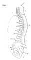
- FIG. 1is a lateral view of the vertebral column showing its normal curvatures (cervical, thoracic, lumbar, sacrococcygeal) and its relationship to the hip bone.
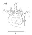
- FIG. 2is the superior view of a typical lumbar vertebra.
- FIG. 3is an elevational view of a spinal fixation device, according to the invention, connected to vertebral bodies of a spinal column.
- FIG. 4is an exploded side view of the fixation device in FIG. 3 .
- FIG. 4Ais a cross-sectional view of the elongate connector.
- FIG. 5is a top view of a screw fixator.
- FIG. 6is a perspective view of a securing cap.
- FIG. 7is a cross sectional view of a screw fixator and pedicle securing cap.
- FIG. 8is a cross sectional view of a screw fixator.
- FIG. 9is an elevational view of a secondary screw.
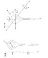
- FIG. 10is a view of an anchoring screw showing directions of perpendicular axes X, Y, Z.
- FIG. 11is a view of the fixation device showing the anchoring screw and the secondary screw.
- FIG. 12is a side view of a fixation device having a screw fixator at both ends.
- the human spine (spinal column) S and vertebra V(see, generally FIGS. 1 , 2 ) will now be described to facilitate an understanding of the present invention.
- the spine Sis a flexible column formed of a series of bones called vertebrae V.
- the spineprovides a partly rigid and partly flexible axis for the body with important roles in posture, support of body weight, locomotion and protection of the spinal cord.
- the spine S(also referred to as the spinal column) generally includes 33 vertebrae, separated into five regions, cervical C, thoracic TH, lumbar L, sacral SA and coccygeal CO.
- the vertebrae in the cervical C, thoracic TH and lumbar L regions of the spineare separated; but those found in the sacral SA and coccygeal CO regions are typically fused, so as to form two bones—the upper bone or sacrum SA, and the lower or terminal bone of the spine, the coccyx CO.
- the bodies of the vertebraeare piled one upon the other, forming a pillar to support the cranium and trunk.
- a typical human spinal columnhas several curves that generally correspond to the different regions of the column.
- the lumbar curve L 1generally commences at the middle of the last thoracic vertebra TH 1 and terminates at the sacro-vertebral angle SA 1 . It is generally convex anteriorly, with the convexity of the lower three lumbar vertebrae typically much greater than that of the upper two.
- the individual vertebrae V of the spine Sinclude a body B and various spinal processes, such as the pedicle P, the lamina LA and the transverse process T.
- the vertebral pedicles Pare two short pieces of bone, which project backward, one on each side, from the upper part of the body of the vertebra, at the line of junction of its posterior and lateral surfaces.
- the spinal processes(also referred to as vertebral arches A) form a vertebral foramen F behind the body(ies) B of the vertebrae V which encompasses and protects the spinal cord.
- the connection between adjacent bonesis called a joint or articulation.
- Adjacent vertebrae Vare connected by an intervertebral joint J, which provides movement in combination with strength.
- the intervertebral joint Jis made up of intervertebral discs and ligaments (including the anterior longitudinal ligament and posterior longitudinal ligament).
- the intervertebral discs Dare plates of fibrocartilage that have an external anulus fibrosus, which surrounds an internal gelatinous nucleus pulposus.
- the lumbar vertebrae Laccount for much of the thickness of the lower trunk in the median plane. In the lumbar region, the vertebral pedicles are very strong, directed backward from the upper part of the bodies. As best shown in FIG. 2 , the body B of a lumbar vertebra L is generally larger than the bodies of vertebrae from other regions of the spine. The body B generally has a lateral diameter d (from side to side) that is greater than the diameter from anterior to posterior d′, providing a broad basis for the support of the superincumbent weight.
- the sacrum SAis a large, generally triangular bone formed from five fused sacral vertebrae. It is situated at the lower part of the spinal column S and at the upper and back part of the pelvic cavity. Its upper part or base SA 2 articulates with the last lumbar vertebra L 5 .
- diseases of the spinecause disruption of the anatomical and functional relationship between adjacent vertebrae.
- Diseases or conditions affecting the lower regions of the spine, particularly the lumbar-sacral areamay cause anatomical or functional disruption between the point of connection between the spine and its major support structure, the pelvis.
- Lumbar sacral stabilizationmay correct various disorders of this anatomical region, such as the displacement of the lumbar vertebrae, degeneration of the intervertebral spaces and fractures of the lumbar spine or sacrum.
- the inventionrelates generally to an apparatus and methods for the management of spinal conditions that may produce instability or deformity. Stability can be increased by fusing the vertebrae to each other or by fusing the lumbar vertebrae to the sacrum.
- fusionrefers to internal fixation of the intervertebral joints to reduce relative movement between the vertebrae. Internal fixation can provide stability in such conditions as vertebral fractures, vertebral body tumors, post traumatic kyphosis and congenital kyphosis.
- Bone fixation devicescan include an elongate rod secured to one or more selected vertebrae.
- spinal fixation mechanismsinclude a screw, such as a pedicle screw, secured to a rod.
- one internal spinal fixation mechanismincludes an elongate transpedicular rod or plate having spaced apertures though which one or more screws are inserted. The screws are fixed to the elongated rod or plate and held in place by a fastening mechanism, such as a nut.
- pedicle screwsare inserted into selected vertebral bodies and are attached to the connector rod.
- the upper portion of each pedicle screwincludes an aperture through which the spinal rod extends, and is held in place by a corresponding connector such as a nut.
- the nutnormally projects beyond the head of the screw.
- Components that are large or bulkycan cause irritation of soft tissues in the vicinity of the implant.
- Transpedicular fixation systemsgenerally include one or more parallel elongate rods which are secured to one or more pedicle screws.
- Typical transpedicular fixation systemsmay not permit the surgeon to vary or control the angulation of the screws segment by segment. Thus, the screws may be forced into a non-anatomic position.
- the rodit is generally preferable to conform the rod to the curvature of the spine, such that the screw is oriented in a direction perpendicular to the surface of the bone (e.g., the pedicle). Variance from a perpendicular relationship may result in constant unidirectional torque of the screw against one surface of the hole in the pedicle receiving the screw. The constant torque may, in turn, cause weakening or breakage of the screw, erosion of the bone or undesirable shifting of the vertebrae-to-adjacent-vertebrae angular relationship.
- a bulky rod locking mechanismmay increase the manipulation required by the surgeon. This, in turn, may increase the difficulty of the procedure, and extend the duration of the surgery, possibly increasing the risk of intra-operative and post-operative complications. For example, a wider surgical incision may be required to place a bulky device, thereby increasing the risk of hemorrhage and infections ultimately delaying healing.
- skeletal bonerefers to bones that are not part of the spinal column S including, but not limited to, the long bones such as the femur, tibia, fibula, humerus, radius and ulnar. Similar considerations discussed with respect to spinal implants apply in these cases.
- a fusion device of the inventionwith reference to implanting the device between adjacent vertebrae V or between lumbar vertebrae L and the sacrum S.
- this descriptionis for explanatory purposes only.
- the devices disclosed hereincan be used at other joints or locations to facilitate bone fusion.
- an embodiment of the inventionis shown stabilizing the vertebrae V of a spinal column S by securing the device to one or more vertebrae V and the sacrum SA.
- a portion of the spinal column Sis shown, including a plurality of lumbar vertebrae V and sacrum SA.
- the spinal fixation device 1includes an elongate connector 2 configured to be secured to at least one bone of a patient. As shown in FIG. 3 , the device 1 can be operably connected to one or more vertebrae V at the pedicle portions P thereof.
- the elongate connector 2is secured to at least one bone of a patient in a manner that maintains a desired relative position between the vertebrae V.
- the elongate connectorcan be secured using one or more screws.
- a single deviceis used.
- more than one deviceis used.
- two devicescan be used, one on each side of the spinal column as shown in FIG. 3 .
- the elongate connector 2has a first end 43 and a second end 44 .
- the elongate connector 2may be any suitable shape such as circular, tangential, square, rectangular or ellipsoid.
- the elongate connector 2(see, in general, FIGS. 4 and 5 ) has as a first surface 27 that is directed toward the vertebrae V, when the device is in use and a second surface 28 that is directed away from the vertebrae V, when the device is in use.
- the first end 43 of the elongate connector 2defines a screw fixator 3 .
- the second end 44defines a screw fixator 3 .
- the second end 44 of the elongate connector 2is configured to engage a secondary screw 4 .
- the elongate connector 2may be constructed in various manners and sizes depending on the size of the patient and the desired stabilization effect.
- the elongate connector 2 and the screw fixator 3are machined out of biologically inert materials capable of surgical sterilization.
- Suitable materialsinclude metals and metal alloys, such as titanium, stainless steel, cobalt-chromium, titanium alloys; superelastic materials such as nitinol; plastics and plastic composites; carbon graphite; and ceramic; etc.
- At least one end of the elongate connector 2defines a screw fixator 3 , which is configured to receive an anchoring screw.
- the screw fixator 3 and the elongate connector 2are integrally formed as a single piece.
- the screw fixator 3 and elongate connector 2can be formed separately and joined by any suitable method, for example, welding, screws, rivets, etc.
- the screw fixator 3(see, in general FIGS. 3 , 4 , and 7 ) has a first major side surface 21 configured to face the vertebra when the device is in use.
- the screw fixator 3also has a second major side surface 22 , on a side opposite the first major side surface, which extends in a direction generally parallel to the first major side surface 21 and is generally oriented away from the vertebra when in use.
- the major side surfacesare connected by a plurality of minor side surfaces.
- the first major side surface 21is contoured to conform to the surface of the vertebra V.
- the major side surfaces 21 and 22 of the screw fixator 3define an opening 41 configured to receive an anchoring screw 5 (See FIGS. 7 , 8 ).
- An inner surface 42 of the opening 41extends from the first side surface 21 to the second side surface 22 .
- the inner diameter (DB) of the opening 41 , proximate the second side surface 22is greater than the inner diameter (Db) of the opening proximate the first side surface 21 .
- the opening proximate the second side surface 22can thus be referred to as the major opening 74 (i.e., a pocket, recess or countersink) and the opening proximate first side surface can be referred to as the minor opening 75 .
- the major opening 74is configured to accommodate at least part of the head 24 of the anchoring screw 5 and the minor opening 75 is configured to accommodate the upper segment 29 of the shaft 31 of the anchoring screw 5 .
- the inner diameter DB of the major opening 74is relatively constant, as is the inner diameter Db of the minor opening 75 , such that, at the point where the two openings abut, a floor 76 is formed in the major opening.
- the floor 76 of the major opening 74where the major opening 74 abuts the minor opening 75 can be concave.
- the inner diameter DB of the major opening 74gradually decreases as it approaches the minor opening 75 , such that the opening 41 extending from the first side surface 21 to the second side surface 22 is frustoconical in shape.
- the entire inner surface 42 of the opening 41 extending from the first major surface side 21 to the second major surface side 22is threaded.
- the inner surface 42 of the opening 41 that is configured to receive the screw head 24is threaded 71
- the remainder of the opening 72 that is configured to receive the upper segment 29 of the shaft 31 of the anchoring screw 5is not (See, FIGS. 7 , 8 ).
- the devicealso includes an anchoring screw 5 which can be coupled to the screw fixator 3 to secure the fixation device 1 to at least one bone of a patient.
- the anchoring screw 5is sized to extend through the screw fixator 3 and into the bone of the patient.
- the anchoring screw 5is configured to secure the fixation device 1 to the pedicle P or transverse process T of a vertebra V. (See, for example, FIG. 2 )
- an anchoring screw 5generally includes a head 24 and a shaft 31 .
- the shaft 31(not shown) is textured to enhance frictional engagement with the bone to which it is secured.
- the shaftcan be included a helically wound thread (i.e., a screw) or other textures, such as ridges or knurls.
- the shaft 31include a upper shaft 29 , extending from a position at or around the midline of the shaft 31 towards the head 24 of the screw 5 and a lower shaft 30 , extending from a position at or around the midline of the shaft 31 away from the head 24 of the screw 5 .
- the upper shaft 29engages the opening 41 of the screw fixator 3 and the lower shaft 30 engages the bone of the patient.
- the upper shaft 29therefore has a diameter that is the same as or less than the diameter of the opening 41 in the screw fixator 3 .
- the upper shaft 29has a diameter that is less than the diameter of the opening 41 .
- the upper shaft 29has a diameter that is less than the diameter of the minor opening 75 .
- the lower shaft 30is textured to enhance frictional engagement of the screw 5 with the bone.
- suitable texturesinclude helical threads, ridges or knurls.
- both the upper 29 and lower 30 shaftcan be textured.
- the lower shaft 30may include a clip mechanism that can be deployed after the screw is inserted into the vertebrae.
- the head 24 of the screw 5is configured and sized such that at least a portion of the head 24 of the anchoring screw 5 is contained within the screw fixator 3 .
- the entire head 24 of the anchoring screw 5is recessed within the opening 41 of the screw fixator 3 once fully implanted.
- the head 24 of the anchoring screw 5is curved or spherical to facilitate rotation of the screw fixator 3 and the elongate connector 2 around the head of the screw 5 .
- the elongate member 2 and screw fixator 3can be rotated around the head 24 of the screw 5 to create movement in at least one of three, mutually perpendicular, dimensions X, Y or Z, similar in function to a ball and socket joint. (See FIG. 10 )
- the anchoring screwcan be configured such that the base 25 of the head 24 rests on the floor 76 when in place.
- the mobility of the “ball and socket joint”allows the surgeon to vary or control the angulation of the device 1 to reduce the likelihood that the screw 24 is forced into a non-anatomic position.
- the “ball and socket” arrangementalso reduces the likelihood that the screw 24 is subjected to constant unidirectional torque that may result in weakening and breakage of the screw, erosion of bone or undesirable shifting of the vertebrae-to-adjacent vertebrae angular relationship.
- the anchoring screw 24may be constructed in various manners and in various sizes.
- the anchoring screw 24can be manufactured using any suitable biologically compatible materials, preferably one that is capable of surgical sterilization. Suitable materials include metals and metal alloys, such as titanium, stainless steel, cobalt-chromium, titanium alloys; superelastic materials such as nitinol; plastics and plastic composites; carbon graphite; bone; and ceramic; etc.
- the devicealso generally includes a securing cap 26 configured to engage the screw fixator 3 and secure the anchoring screw 5 to the screw fixator 3 (See, in general, FIGS. 4 , 6 ).
- the securing cap 26includes a body 51 having a leading end 52 and a trailing end 53 .
- An external surface 54extends from the leading end 52 to the trailing end 53 . (See, FIG. 6 ).
- the leading end 52has a concave surface configured to engage a rounded head 24 of the anchoring screw 5 .
- the external surface 54 of the securing cap 26can be threaded with threads having a pitch and diameter corresponding to the threaded inner surface 42 of the opening 41 of the screw fixator 3 (See, FIGS. 8 , 6 ).
- the threaded inner surface 71 of the opening 41permits the insertion of a securing cap 26 with subsequent tightening/locking of the securing cap 26 within the screw fixator 3 .
- the securing cap 26is secured to the screw fixator 3 by other mechanisms such as a snap fit, ratchet structure.
- the securing cap 26is secured to the screw fixator 3 , such that the trailing end 53 of the securing cap 26 lies substantially in the same plane as the first major side surface 22 of the screw fixator 3 .
- This arrangementreduces the profile of the implanted fixation device 1 , because the upper portion of the anchoring screw 5 is not held in place by a connector such as a nut, which protrudes above the first major side 22 of the screw fixator 3 .
- the reduced profilereduces the likelihood of soft tissue irritation or stress on the facet joints of the vertebrae.
- the securing cap 26may be constructed in various manners and in various sizes.
- the securing cap 26can be manufactured using any suitable biologically inert materials, preferably one that is capable of surgical sterilization. Suitable materials include metals and metal alloys, such as titanium, stainless steel, cobalt-chromium, titanium alloys; superelastic materials such as nitinol; plastics and plastic composites; carbon graphite; bone; and ceramic; etc.
- the second end of the elongate connector 2is operably connected to the same or another bone of a patient as the first end.
- the second end of the elongate connectoris configured to engage a secondary screw 4 (See FIGS. 3 and 11 ). Any suitable commercially available screw, for example, commercially available pedicle screws, may be used to secure the second end of the elongate connector 2 .
- the secondary screw 4includes a head 83 and a shaft 88 .
- the head 83is generally configured to engage the elongate connector 2
- the shaft 88is generally configured to be secured to a patient's bone.
- aperturesare located along the length of the elongate connector 2 , such that one or more secondary screws 4 can be inserted through the aperture and secured to a bone.
- the secondary screw 4includes an engagement member that is configured to receive and secure the elongate connector 2 .
- the head 83 of the secondary screw 4can be constructed as a loop that is configured to receive the elongate connector 2 (See, FIGS. 9 , 11 ).
- the head 83 of the secondary screw 4can be configured as a “U” shaped saddle that is adapted to receive the elongate connector 2 . A securing device can then be used to secure the elongate connector 2 within the saddle.
- the head 83 of the secondary screw 4is operably connected to the shaft 88 .
- the shaft 88is configured to engage the bone of a patient.
- the shaft 88is textured to enhance frictional engagement of the screw 4 with the bone. (See, FIG. 4 ) Examples of suitable textures include helical threads, ridges or knurls.
- suitable texturesinclude helical threads, ridges or knurls.
- the lower shaft 88may include a clip mechanism that can be deployed after the screw is inserted into the vertebrae.
- the secondary screw 4may be constructed in various manners and in various sizes.
- the secondary screwcan be manufactured using any suitable biologically inert materials, preferably one that is capable of surgical sterilization. Suitable materials include metals and metal alloys, such as titanium, stainless steel, cobalt-chromium, titanium alloys; superelastic materials such as nitinol; plastics and plastic composites; carbon graphite; bone; and ceramic; etc.
- the device of the inventioncan be used to stabilize one or more bones of a patient. Although the method is described below in connection with stabilizing one or more adjacent vertebrae, the method is suitable for use in stabilizing other bones, such as skeletal bones.
- the bone that is to be stabilizedis first accessed.
- the spinal columncan be accessed, by a midline posterior approach. Suitable procedures are known.
- the first end 43 of the elongate connector 2is secured to the bone.
- an anchoring screw 5is inserted into the opening 41 defined by the screw fixator 3 .
- the shaft 31 of the anchoring screw 5is secured to the bone by, for example, threadably advancement therein.
- the shaft 31can be secured to the pedicle P of a vertebrae V.
- the elongate connector 2is positioned along the spinal column S.
- the anchoring screw 5is secured by engaging a securing cap 26 to the pedicle screw fixator 3 (See, generally, FIGS. 4 , 3 ).
- the second end 44 of the elongate connector 2is then secured to the same or another bone via a secondary screw, or a similar screw fixator 3 and anchoring screw 5 arrangement.
- the relative curvature of the head and floorallow angular orientation of connector 2 to be adjusted after fixation screw is in place.
- the patientis then closed with the device in place.
Landscapes
- Health & Medical Sciences (AREA)
- Orthopedic Medicine & Surgery (AREA)
- Life Sciences & Earth Sciences (AREA)
- Surgery (AREA)
- Neurology (AREA)
- Heart & Thoracic Surgery (AREA)
- Engineering & Computer Science (AREA)
- Biomedical Technology (AREA)
- Nuclear Medicine, Radiotherapy & Molecular Imaging (AREA)
- Medical Informatics (AREA)
- Molecular Biology (AREA)
- Animal Behavior & Ethology (AREA)
- General Health & Medical Sciences (AREA)
- Public Health (AREA)
- Veterinary Medicine (AREA)
- Surgical Instruments (AREA)
Abstract
Description
Claims (7)
Priority Applications (1)
| Application Number | Priority Date | Filing Date | Title |
|---|---|---|---|
| US10/235,227US7198627B2 (en) | 2001-09-07 | 2002-09-04 | Spinal fixation device and method |
Applications Claiming Priority (2)
| Application Number | Priority Date | Filing Date | Title |
|---|---|---|---|
| US31788901P | 2001-09-07 | 2001-09-07 | |
| US10/235,227US7198627B2 (en) | 2001-09-07 | 2002-09-04 | Spinal fixation device and method |
Publications (2)
| Publication Number | Publication Date |
|---|---|
| US20030144666A1 US20030144666A1 (en) | 2003-07-31 |
| US7198627B2true US7198627B2 (en) | 2007-04-03 |
Family
ID=27616385
Family Applications (1)
| Application Number | Title | Priority Date | Filing Date |
|---|---|---|---|
| US10/235,227Expired - Fee RelatedUS7198627B2 (en) | 2001-09-07 | 2002-09-04 | Spinal fixation device and method |
Country Status (1)
| Country | Link |
|---|---|
| US (1) | US7198627B2 (en) |
Cited By (15)
| Publication number | Priority date | Publication date | Assignee | Title |
|---|---|---|---|---|
| US20070225711A1 (en)* | 2006-03-22 | 2007-09-27 | Ensign Michael D | Low top bone fixation system and method for using the same |
| US20080015586A1 (en)* | 2006-06-07 | 2008-01-17 | Disc Motion Technologies, Inc. | Pedicle screw system |
| US20090105770A1 (en)* | 2007-10-23 | 2009-04-23 | Gregory Berrevoets | Rod Coupling Assembly and Methods for Bone Fixation |
| US20100204735A1 (en)* | 2009-02-11 | 2010-08-12 | Gephart Matthew P | Wide Angulation Coupling Members For Bone Fixation System |
| US20110060373A1 (en)* | 2009-09-09 | 2011-03-10 | Russell Thomas A | Bone screws and methods of use thereof |
| US20110152939A1 (en)* | 2009-12-19 | 2011-06-23 | Aldridge James H | Apparatus and system for vertebrae stabilization and curvature correction, and methods of making and using same |
| US8506601B2 (en) | 2008-10-14 | 2013-08-13 | Pioneer Surgical Technology, Inc. | Low profile dual locking fixation system and offset anchor member |
| US8790375B2 (en) | 2011-03-18 | 2014-07-29 | Raed M. Ali, M.D., Inc. | Transpedicular access to intervertebral spaces and related spinal fusion systems and methods |
| US9017387B2 (en) | 2009-12-19 | 2015-04-28 | James H. Aldridge | Apparatus and system for vertebrae stabilization and curvature correction, and methods of making and using same |
| US9265620B2 (en) | 2011-03-18 | 2016-02-23 | Raed M. Ali, M.D., Inc. | Devices and methods for transpedicular stabilization of the spine |
| US9271742B2 (en) | 2012-08-09 | 2016-03-01 | Wilson Theophilo Asfora | System for joint fusion |
| US9861495B2 (en) | 2013-03-14 | 2018-01-09 | Raed M. Ali, M.D., Inc. | Lateral interbody fusion devices, systems and methods |
| US9861411B2 (en) | 2011-06-28 | 2018-01-09 | Spinologics Inc. | Bone screw, and bone fixation system and method |
| US9993276B2 (en) | 2013-03-15 | 2018-06-12 | Innovision, Inc. | Bone screws and methods of use thereof |
| US10687962B2 (en) | 2013-03-14 | 2020-06-23 | Raed M. Ali, M.D., Inc. | Interbody fusion devices, systems and methods |
Families Citing this family (12)
| Publication number | Priority date | Publication date | Assignee | Title |
|---|---|---|---|---|
| FR2812185B1 (en) | 2000-07-25 | 2003-02-28 | Spine Next Sa | SEMI-RIGID CONNECTION PIECE FOR RACHIS STABILIZATION |
| DE102004050040A1 (en)* | 2004-10-08 | 2006-04-20 | Aesculap Ag & Co. Kg | bone screw |
| US20060229607A1 (en)* | 2005-03-16 | 2006-10-12 | Sdgi Holdings, Inc. | Systems, kits and methods for treatment of the spinal column using elongate support members |
| US20060241600A1 (en)* | 2005-03-23 | 2006-10-26 | Ensign Michael D | Percutaneous pedicle screw assembly |
| US8257355B2 (en)* | 2006-06-07 | 2012-09-04 | Spinefrontier Inc. | Methods and devices for static or dynamic spine stabilization |
| WO2008034130A2 (en)* | 2006-09-15 | 2008-03-20 | Alpinespine Llc | Dynamic pedicle screw system |
| US8034081B2 (en) | 2007-02-06 | 2011-10-11 | CollabComl, LLC | Interspinous dynamic stabilization implant and method of implanting |
| US9247973B2 (en) | 2007-09-28 | 2016-02-02 | DePuy Synthes Products, Inc. | Anti-microbial implant |
| US20100114165A1 (en)* | 2008-11-04 | 2010-05-06 | Abbott Spine, Inc. | Posterior dynamic stabilization system with pivoting collars |
| US9078701B2 (en)* | 2009-11-09 | 2015-07-14 | Centinel Spine, Inc. | System and method for stabilizing a posterior fusion over motion segments |
| WO2012006064A1 (en)* | 2010-06-28 | 2012-01-12 | K2M, Inc. | Spinal stabilization system |
| US11660126B1 (en)* | 2019-06-28 | 2023-05-30 | Advance Research System, Llc | Iliac anchor system |
Citations (15)
| Publication number | Priority date | Publication date | Assignee | Title |
|---|---|---|---|---|
| US5147361A (en)* | 1989-11-29 | 1992-09-15 | Asahi Kogaku Kogyo Kabushiki Kaisha | Vertebral connecting plate |
| US5282863A (en) | 1985-06-10 | 1994-02-01 | Charles V. Burton | Flexible stabilization system for a vertebral column |
| US5300073A (en)* | 1990-10-05 | 1994-04-05 | Salut, Ltd. | Sacral implant system |
| US5324290A (en)* | 1992-09-24 | 1994-06-28 | Danek Medical, Inc. | Anterior thoracolumbar plate |
| US5429639A (en)* | 1993-05-17 | 1995-07-04 | Tornier S.A. | Spine fixator for holding a vertebral column |
| US5531746A (en)* | 1995-04-13 | 1996-07-02 | Fastenetix, L.L.C. | Posterior spinal polyaxial locking lateral mass screw plate assembly |
| US5549608A (en) | 1995-07-13 | 1996-08-27 | Fastenetix, L.L.C. | Advanced polyaxial locking screw and coupling element device for use with rod fixation apparatus |
| US5586984A (en) | 1995-07-13 | 1996-12-24 | Fastenetix, L.L.C. | Polyaxial locking screw and coupling element assembly for use with rod fixation apparatus |
| US5676666A (en) | 1994-08-23 | 1997-10-14 | Spinetech, Inc. | Cervical spine stabilization system |
| US5868749A (en) | 1996-04-05 | 1999-02-09 | Reed; Thomas M. | Fixation devices |
| US6010503A (en) | 1998-04-03 | 2000-01-04 | Spinal Innovations, Llc | Locking mechanism |
| US6022350A (en)* | 1996-05-13 | 2000-02-08 | Stryker France S.A. | Bone fixing device, in particular for fixing to the sacrum during osteosynthesis of the backbone |
| US6056749A (en) | 1999-03-15 | 2000-05-02 | Spineology, Inc. | Method and device for fixing and correcting spondylolisthesis anteriorly |
| US6398783B1 (en) | 1997-02-11 | 2002-06-04 | Sulzer Spine-Tech Inc. | Multi-lock anterior cervical plate |
| US6599290B2 (en)* | 2001-04-17 | 2003-07-29 | Ebi, L.P. | Anterior cervical plating system and associated method |
- 2002
- 2002-09-04USUS10/235,227patent/US7198627B2/ennot_activeExpired - Fee Related
Patent Citations (17)
| Publication number | Priority date | Publication date | Assignee | Title |
|---|---|---|---|---|
| US5282863A (en) | 1985-06-10 | 1994-02-01 | Charles V. Burton | Flexible stabilization system for a vertebral column |
| US5147361A (en)* | 1989-11-29 | 1992-09-15 | Asahi Kogaku Kogyo Kabushiki Kaisha | Vertebral connecting plate |
| US5300073A (en)* | 1990-10-05 | 1994-04-05 | Salut, Ltd. | Sacral implant system |
| US5324290A (en)* | 1992-09-24 | 1994-06-28 | Danek Medical, Inc. | Anterior thoracolumbar plate |
| US5429639A (en)* | 1993-05-17 | 1995-07-04 | Tornier S.A. | Spine fixator for holding a vertebral column |
| US5676666A (en) | 1994-08-23 | 1997-10-14 | Spinetech, Inc. | Cervical spine stabilization system |
| US5607426A (en)* | 1995-04-13 | 1997-03-04 | Fastenletix, L.L.C. | Threaded polyaxial locking screw plate assembly |
| US5531746A (en)* | 1995-04-13 | 1996-07-02 | Fastenetix, L.L.C. | Posterior spinal polyaxial locking lateral mass screw plate assembly |
| US5586984A (en) | 1995-07-13 | 1996-12-24 | Fastenetix, L.L.C. | Polyaxial locking screw and coupling element assembly for use with rod fixation apparatus |
| US5549608A (en) | 1995-07-13 | 1996-08-27 | Fastenetix, L.L.C. | Advanced polyaxial locking screw and coupling element device for use with rod fixation apparatus |
| US5868749A (en) | 1996-04-05 | 1999-02-09 | Reed; Thomas M. | Fixation devices |
| US5968047A (en) | 1996-04-05 | 1999-10-19 | Reed; Thomas Mills | Fixation devices |
| US6022350A (en)* | 1996-05-13 | 2000-02-08 | Stryker France S.A. | Bone fixing device, in particular for fixing to the sacrum during osteosynthesis of the backbone |
| US6398783B1 (en) | 1997-02-11 | 2002-06-04 | Sulzer Spine-Tech Inc. | Multi-lock anterior cervical plate |
| US6010503A (en) | 1998-04-03 | 2000-01-04 | Spinal Innovations, Llc | Locking mechanism |
| US6056749A (en) | 1999-03-15 | 2000-05-02 | Spineology, Inc. | Method and device for fixing and correcting spondylolisthesis anteriorly |
| US6599290B2 (en)* | 2001-04-17 | 2003-07-29 | Ebi, L.P. | Anterior cervical plating system and associated method |
Non-Patent Citations (3)
| Title |
|---|
| Dubois, et al. Dynamic Neutralization: A New Concept for Restabilization of the Spine, from "Lumbar Segmental Instability" pp. 233-240, Lippincott Williams & Wilkins Healthcare, 1999. |
| Dynesys(TM) brochure, Sulzer Orthopedics Ltd. 1998. |
| Scharer, et al Static and Dynamic Biomechanical tests of a Dynamic Neutralization System for the Spine, ESS 98 Innsbruck. |
Cited By (41)
| Publication number | Priority date | Publication date | Assignee | Title |
|---|---|---|---|---|
| US7828829B2 (en) | 2006-03-22 | 2010-11-09 | Pioneer Surgical Technology Inc. | Low top bone fixation system and method for using the same |
| US20070225711A1 (en)* | 2006-03-22 | 2007-09-27 | Ensign Michael D | Low top bone fixation system and method for using the same |
| US20080015586A1 (en)* | 2006-06-07 | 2008-01-17 | Disc Motion Technologies, Inc. | Pedicle screw system |
| US8277485B2 (en) | 2006-06-07 | 2012-10-02 | Spinadyne, Inc. | Pedicle screw system |
| US8398683B2 (en) | 2007-10-23 | 2013-03-19 | Pioneer Surgical Technology, Inc. | Rod coupling assembly and methods for bone fixation |
| US20090105770A1 (en)* | 2007-10-23 | 2009-04-23 | Gregory Berrevoets | Rod Coupling Assembly and Methods for Bone Fixation |
| US8506601B2 (en) | 2008-10-14 | 2013-08-13 | Pioneer Surgical Technology, Inc. | Low profile dual locking fixation system and offset anchor member |
| US20100204735A1 (en)* | 2009-02-11 | 2010-08-12 | Gephart Matthew P | Wide Angulation Coupling Members For Bone Fixation System |
| US8636778B2 (en) | 2009-02-11 | 2014-01-28 | Pioneer Surgical Technology, Inc. | Wide angulation coupling members for bone fixation system |
| US11766283B2 (en) | 2009-09-09 | 2023-09-26 | Innovision, Inc. | Bone screws and methods of use thereof |
| US11147603B2 (en) | 2009-09-09 | 2021-10-19 | Zimmer Biomet Spine, Inc. | Bone screws and methods of use thereof |
| US20110060373A1 (en)* | 2009-09-09 | 2011-03-10 | Russell Thomas A | Bone screws and methods of use thereof |
| US9333018B2 (en) | 2009-09-09 | 2016-05-10 | Innovision, Inc. | Bone screws and methods of use thereof |
| US8574273B2 (en) | 2009-09-09 | 2013-11-05 | Innovision, Inc. | Bone screws and methods of use thereof |
| US9936992B2 (en) | 2009-09-09 | 2018-04-10 | Innovision, Inc. | Bone screws and methods of use thereof |
| US9017387B2 (en) | 2009-12-19 | 2015-04-28 | James H. Aldridge | Apparatus and system for vertebrae stabilization and curvature correction, and methods of making and using same |
| US20110152939A1 (en)* | 2009-12-19 | 2011-06-23 | Aldridge James H | Apparatus and system for vertebrae stabilization and curvature correction, and methods of making and using same |
| US8425566B2 (en) | 2009-12-19 | 2013-04-23 | James H. Aldridge | Apparatus and system for vertebrae stabilization and curvature correction, and methods of making and using same |
| US20110152938A1 (en)* | 2009-12-19 | 2011-06-23 | Aldridge James H | Apparatus and system for vertebrae stabilization and curvature correction, and methods of making and using same |
| US8465523B2 (en) | 2009-12-19 | 2013-06-18 | James H. Aldridge | Apparatus and system for vertebrae stabilization and curvature correction, and methods of making and using same |
| US8790375B2 (en) | 2011-03-18 | 2014-07-29 | Raed M. Ali, M.D., Inc. | Transpedicular access to intervertebral spaces and related spinal fusion systems and methods |
| US9265620B2 (en) | 2011-03-18 | 2016-02-23 | Raed M. Ali, M.D., Inc. | Devices and methods for transpedicular stabilization of the spine |
| US10987228B2 (en) | 2011-03-18 | 2021-04-27 | Raed M. Ali, M.D., Inc. | Devices and methods for transpedicular stabilization of the spine |
| US9980750B2 (en) | 2011-03-18 | 2018-05-29 | Raed M. Ali, M.D., Inc. | Spinal fusion devices and systems |
| US10117694B2 (en) | 2011-06-28 | 2018-11-06 | Spinologics Inc. | Bone screw, and bone fixation system and method |
| US9861411B2 (en) | 2011-06-28 | 2018-01-09 | Spinologics Inc. | Bone screw, and bone fixation system and method |
| US10987144B2 (en) | 2012-08-09 | 2021-04-27 | Asfora Ip, Llc | Screw for joint fusion |
| US9271742B2 (en) | 2012-08-09 | 2016-03-01 | Wilson Theophilo Asfora | System for joint fusion |
| US9566100B2 (en) | 2012-08-09 | 2017-02-14 | Asfora Ip, Llc | Screw for joint fusion |
| US9271743B2 (en) | 2012-08-09 | 2016-03-01 | Wilson Theophilo Asfora | System for joint fusion |
| US9526548B2 (en) | 2012-08-09 | 2016-12-27 | Asfora Ip, Llc | System for joint fusion |
| US10251688B2 (en) | 2012-08-09 | 2019-04-09 | Asfora Ip, Llc | Screw for joint fusion |
| US9295488B2 (en) | 2012-08-09 | 2016-03-29 | Wilson T. Asfora | Joint fusion |
| US10045857B2 (en) | 2013-03-14 | 2018-08-14 | Raed M. Ali, M.D., Inc. | Lateral interbody fusion devices, systems and methods |
| US10687962B2 (en) | 2013-03-14 | 2020-06-23 | Raed M. Ali, M.D., Inc. | Interbody fusion devices, systems and methods |
| US10548742B2 (en) | 2013-03-14 | 2020-02-04 | Raed M. Ali, M.D., Inc. | Lateral interbody fusion devices, systems and methods |
| US11304824B2 (en) | 2013-03-14 | 2022-04-19 | Raed M. Ali, M.D., Inc. | Interbody fusion devices, systems and methods |
| US11413162B2 (en) | 2013-03-14 | 2022-08-16 | Raed M. Ali, M.D., Inc. | Spinal fusion devices, systems and methods |
| US9861495B2 (en) | 2013-03-14 | 2018-01-09 | Raed M. Ali, M.D., Inc. | Lateral interbody fusion devices, systems and methods |
| US10751102B2 (en) | 2013-03-15 | 2020-08-25 | Innovision, Inc. | Bone screws and methods of use thereof |
| US9993276B2 (en) | 2013-03-15 | 2018-06-12 | Innovision, Inc. | Bone screws and methods of use thereof |
Also Published As
| Publication number | Publication date |
|---|---|
| US20030144666A1 (en) | 2003-07-31 |
Similar Documents
| Publication | Publication Date | Title |
|---|---|---|
| US7198627B2 (en) | Spinal fixation device and method | |
| US7883532B2 (en) | Vertebral pars interarticularis clamp a new spine fixation device, instrumentation, and methodology | |
| US10376380B2 (en) | Devices and methods for cervical lateral fixation | |
| US8926700B2 (en) | Spinal facet joint implant | |
| CN102512231B (en) | Interlaminar-interspinous vertebral stabilization system | |
| US6533790B1 (en) | Self-guided pedical screw | |
| US20110178552A1 (en) | Vertebral pars interarticularis clamp a new spine fixation device, instrumentation, and methodology | |
| US8097020B2 (en) | Pedicle dynamic facet arthroplasty system and method | |
| US20120035667A1 (en) | Locking mechanisms for pivoting bone anchors | |
| AU1181295A (en) | Transverse link for spinal implant system | |
| US9801662B2 (en) | Spinal stabilization system | |
| US20090292308A1 (en) | Spinal fixation system | |
| US20120059422A1 (en) | Methods for compression fracture treatment with spinous process fixation systems | |
| US9095378B2 (en) | Spinal stabilization system | |
| US20160128734A1 (en) | Threaded Setscrew Crosslink | |
| US12185997B2 (en) | Pedicle fixation system | |
| US20120116458A1 (en) | Modular pivotable screw assembly and method | |
| US20150230833A1 (en) | Spinal Facet Implant with Spherical Implant Apposition Surface and Bone Bed and Methods of Use |
Legal Events
| Date | Code | Title | Description |
|---|---|---|---|
| AS | Assignment | Owner name:ZIMMER SPINE, INC., TEXAS Free format text:CHANGE OF NAME;ASSIGNOR:CENTERPULSE SPINE-TECH INC.;REEL/FRAME:015642/0498 Effective date:20040429 | |
| AS | Assignment | Owner name:CENTERPULSE SPINE-TECH INC., MINNESOTA Free format text:CHANGE OF NAME;ASSIGNOR:SULZER SPINE-TECH INC.;REEL/FRAME:017479/0561 Effective date:20020930 Owner name:SULZER SPINE-TECH, INC., MINNESOTA Free format text:ASSIGNMENT OF ASSIGNORS INTEREST;ASSIGNOR:BAGGA, CHARANPREET;REEL/FRAME:017479/0483 Effective date:20021126 Owner name:SPINE-TECH, INC., MINNESOTA Free format text:EMPLOYMENT AGREEMENT;ASSIGNOR:GRAY, ERIC L.;REEL/FRAME:017479/0390 Effective date:19980115 Owner name:ZIMMER SPINE, INC., MINNESOTA Free format text:ASSIGNMENT OF ASSIGNORS INTEREST;ASSIGNOR:VENTRE, CARLO;REEL/FRAME:017479/0563 Effective date:20051213 Owner name:SULZER SPINE-TECH INC., MINNESOTA Free format text:MERGER;ASSIGNORS:SPINE-TECH, INC.;SULZER SPINE-TECH INC.;REEL/FRAME:017479/0313 Effective date:19980401 | |
| FPAY | Fee payment | Year of fee payment:4 | |
| REMI | Maintenance fee reminder mailed | ||
| LAPS | Lapse for failure to pay maintenance fees | ||
| STCH | Information on status: patent discontinuation | Free format text:PATENT EXPIRED DUE TO NONPAYMENT OF MAINTENANCE FEES UNDER 37 CFR 1.362 | |
| FP | Lapsed due to failure to pay maintenance fee | Effective date:20150403 |