US7198170B2 - Closure and container system and method for sealing a closure on a container - Google Patents
Closure and container system and method for sealing a closure on a containerDownload PDFInfo
- Publication number
- US7198170B2 US7198170B2US10/753,850US75385004AUS7198170B2US 7198170 B2US7198170 B2US 7198170B2US 75385004 AUS75385004 AUS 75385004AUS 7198170 B2US7198170 B2US 7198170B2
- Authority
- US
- United States
- Prior art keywords
- closure
- container
- tamper
- lug
- lock
- Prior art date
- Legal status (The legal status is an assumption and is not a legal conclusion. Google has not performed a legal analysis and makes no representation as to the accuracy of the status listed.)
- Expired - Fee Related, expires
Links
Images


Classifications
- B—PERFORMING OPERATIONS; TRANSPORTING
- B65—CONVEYING; PACKING; STORING; HANDLING THIN OR FILAMENTARY MATERIAL
- B65D—CONTAINERS FOR STORAGE OR TRANSPORT OF ARTICLES OR MATERIALS, e.g. BAGS, BARRELS, BOTTLES, BOXES, CANS, CARTONS, CRATES, DRUMS, JARS, TANKS, HOPPERS, FORWARDING CONTAINERS; ACCESSORIES, CLOSURES, OR FITTINGS THEREFOR; PACKAGING ELEMENTS; PACKAGES
- B65D41/00—Caps, e.g. crown caps or crown seals, i.e. members having parts arranged for engagement with the external periphery of a neck or wall defining a pouring opening or discharge aperture; Protective cap-like covers for closure members, e.g. decorative covers of metal foil or paper
- B65D41/02—Caps or cap-like covers without lines of weakness, tearing strips, tags, or like opening or removal devices
- B65D41/04—Threaded or like caps or cap-like covers secured by rotation
- B65D41/06—Threaded or like caps or cap-like covers secured by rotation with bayonet cams, i.e. removed by first pushing axially to disengage the cams and then rotating
- B—PERFORMING OPERATIONS; TRANSPORTING
- B65—CONVEYING; PACKING; STORING; HANDLING THIN OR FILAMENTARY MATERIAL
- B65D—CONTAINERS FOR STORAGE OR TRANSPORT OF ARTICLES OR MATERIALS, e.g. BAGS, BARRELS, BOTTLES, BOXES, CANS, CARTONS, CRATES, DRUMS, JARS, TANKS, HOPPERS, FORWARDING CONTAINERS; ACCESSORIES, CLOSURES, OR FITTINGS THEREFOR; PACKAGING ELEMENTS; PACKAGES
- B65D2401/00—Tamper-indicating means
- B65D2401/15—Tearable part of the closure
- B65D2401/25—Non-metallic tear-off strips
Definitions
- the present inventionrelates generally to packages and containers. More particularly, the present invention regards a tamper-evident arrangement that maintains a seal between the closure and the container until after the tamper-evident arrangement has been severed from the closure.
- Tamper evident sealshave been used to increase consumer safety by showing whether a package has been opened after being produced.
- Embodiments of tamper evident indicatorsinclude a pop-up button in the center of a package and a break-away seal connected to the lower edge of a lid.
- the pop-up buttonhas the disadvantage that it may be difficult to ascertain whether the seal has been broken.
- the break-away lower lid sectionmay be too sensitive and may break away inadvertently during normal jostling. Alternatively, the break-away lower lid section may be insensitive to tampering or pilfering, and may not break away until after the seal between the closure and the container has been breached.
- U.S. Pat. No. 4,448,318is believed to describe a screw threaded closure for containers having a tamper-evident ring or band connected to the lower terminal edge of a skirt by at least a pair of fracturable bridge means.
- the bridge meansare oriented in a predetermined manner relative to one another to effect sequential breaking in a given pattern upon relative movement of the cap portion and ring in the direction.
- U.S. Pat. No. 4,534,480is believed to describe a tamper evident closure for use on a screw threaded neck of a container.
- the closureincludes a tamper evident band joined to the cap's sidewall by a plurality of bridge strips that are circumferentially aligned with ratchet teeth on the tamper evident band.
- the ratchet lugsstop the ratchet teeth and the tamper evident band from moving so that the band is separated from the cap, thereby providing an indication of tampering with the closure.
- U.S. Pat. No. 4,567,991is believed to describe a tamper indicating child resistant package including a screw type closure for use with a container having a threaded neck portion.
- a tamper indicating meansis provided to maintain the lock element in circumferentially aligned relationship relative to the lock member, and is further provided with stop elements to cooperatively engage the stop lugs on the container.
- the tamper indicating meansprevents removal of the closure before separating the tamper indicating means from the remainder of the closure, thereby giving evidence of tampering with the container.
- U.S. Pat. No. 4,828,127is believed to describe a tamper-evident screw-threaded closure in which the skirt of a cap is joined at its lower edge to a band by integral elongated breakable webs.
- the bandhas lugs which oppose circumferential, rather than axial, movement in the unscrewing direction.
- U.S. Pat. No. 4,936,475is believed to describe a tamper indicating closure and closure-container package in which a tamper indicating skirt depends from the bottom of the annular wall of a standard threaded cap.
- the skirtincludes a plurality of equally spaced depending ribs that are joined at their extremities by a flexible ring. The ring and the skirt ribs pass over lugs on the container neck when the cap is being threaded onto the closure. When the cap is being unthreaded, the lugs engage the rings to sever them indicating tampering or prior opening.
- U.S. Pat. No. 5,320,233is believed to describe a lug cap or closure that is used in combination with a container for indicating that the container has been opened so as to indicate loss of seal or tampering.
- the lug capincludes an upper cap portion and a depending tamper or pilfer band, each having a series of circumferentially spaced lugs.
- the upper cap portion and the pilfer bandare joined by a plurality of frangible bridges.
- the container finishincludes combination camming/locking projections for locking the lugs into a locked position and for separating the pilfer band from the upper cap portion by a camming action when the container is opened.
- U.S. Pat. No. 5,829,613is believed to describe a container closure system comprising a threaded cap and a threaded neck wherein the cap is affixed to the neck by direct axial application so that the mating threads slip past one another and into engagement.
- the cap and neckinclude tamper-indication means to prevent removal of the cap without activation thereof.
- U.S. Pat. No. 5,449,078is believed to describe a combination of a container and a safety cap therefor in which the safety cap has a closure plane and a circumferential outer skirt for engaging a container and has a circumferential resilient depending inner member.
- the containerhas a rigid wall having an end for engagement with the cap internally of the outer skirt.
- the wallis tapered from a smaller diameter portion adjacent the closure plane of the cap to a larger diameter portion remote from the closure plane of the cap.
- the tapered wall of the containerengages internally the resilient inner member of the cap and the larger diameter portion of the wall expands the resilient inner member outwardly to provide a working seal of the container as well as a bias on the cap in a direction of removal of the cap.
- the combinationalso includes means disposed on the container remotely from the end of the rigid wall and cooperative means on the cap for preventing the cap from being removed from the container without depression of the cap on the container and rotation of the cap on the container.
- the containerincludes means for providing a tamper evident seal, whereby it is evident that the contents have been sealed with a material protecting the contents of the container. Any penetration of the seal prior to the removal and destruction of the seal by the user will be evidence of the lack of integrity of the contents of the container.
- An exemplary embodiment of the present inventionincludes a one-piece lug-style closure for a lug-style container.
- the tamper-evident closureis designed to fracture breakable connectors upon removal before the sealing liner is separated from the container's sealing surface.
- the closureis designed with groups of two lugs that are separated from each other by a line of breakable connectors.
- the upper lugprovides the clamping force to create a seal of the container and the lower lug provides the locking of the cap upon the container.
- the lower lugprevents the lower cap wall from moving upon cap removal, causing the breakable connectors to fracture, thereby indicating tampering.
- the lower cap wallwill drop down and be separated vertically from the upper wall of the closure.
- the cap's breakable connectorsfracture when the cap turns, before the upper cap wall rises vertically and separates from the lower wall.
- the container lugsare designed with a cam surface and a clamping surface for the cap's sealing lug. A triangular shaped vertical wall permits the cap's lock lug to cam over and lock the lower cap wall with the container.
- a systemincludes a container including a sidewall and a bottom wall.
- a neck region on the sidewallmay be adjacent to an opening.
- the openingmay be opposite the bottom wall.
- the containermay include projections spaced around the neck region.
- Each of the projectionsmay include a cam surface, a lock surface, a ramp, and a clamping surface.
- the systemmay include a closure including a closure plane and a circumferentially depending outer skirt extending from the closure plane.
- a tamper-evident arrangementmay be frangibly connected to an edge of the outer skirt opposite the closure plane. Pairs of lugs may be spaced around an inner sidewall formed by the outer skirt and the tamper-evident arrangement.
- a lock lug of each pair of lugsmay be arranged on the tamper-evident arrangement and a sealing lug of each pair of lugs may be arranged on the outer skirt.
- Each lock lugmay be adapted to engage the cam surface of a corresponding projection during an application operation.
- the lock lugmay be adapted to engage the lock surface of the corresponding projection after the application operation.
- Each sealing lugmay be adapted to engage the ramp of the corresponding projection during the application operation.
- the sealing lugmay be adapted to engage the clamping surface of the corresponding projection after the application operation.
- a number of pairs of lugsmay be equal to a number of projections.
- the closure and the containermay cooperate to provide a tamper-evident closure with the container after the initial application operation.
- the lock lugmay engage the lock surface to prevent removal of the closure until the tamper-evident arrangement detaches from the outer skirt.
- the sealing lugmay engage the clamping surface until after the tamper-evident arrangement detaches completely from the outer skirt.
- the tamper-evident arrangementmay detach from the outer skirt during a first removal operation.
- the closure and the containermay cooperate to provide a delay-release mechanism.
- the delay-release mechanismmay include the sealing lug and the clamping surface.
- the systemmay further include a child-resistant lock surface adapted to engage the sealing lug in a sealed position and an inner wall on the closure arranged radially inward of the outer skirt.
- the inner wallmay be adapted to engage the neck region of the container.
- the neck region or the inner wallmay be tapered to provide a force biasing the closure open with respect to the container.
- the child-resistant lock surfacemay prevent removal of the closure from the container until a further force opposing the force biasing the closure open is provided.
- a method for sealing a closure on a container in a tamper-evident mannerincludes rotating the closure with respect to the container in a tightening direction until a lock lug of each of a pair of lugs first engages a cam surface of a corresponding projection spaced around a neck region of the container and further rotating the closure with respect to the container in the tightening direction until the lock lug of each pair of lugs engages a lock surface of the corresponding projection.
- the lock lug of each pair of lugsmay be arranged on a tamper-evident arrangement and a sealing lug of each pair of lugs may be arranged on an outer skirt of the closure.
- each sealing lugmay be adapted to engage a ramp of the corresponding projection during the rotating operation and to engage a clamping surface of the corresponding projection after the further rotating operation.
- the pairs of lugsare spaced around an inner sidewall of the outer skirt of the closure and the tamper-evident arrangement.
- the containermay include a sidewall and bottom wall, the neck region being on the sidewall and being adjacent to an opening, the opening opposite the bottom wall.
- the closuremay include a closure plane and the outer skirt circumferentially extending from the closure plane; and the tamper-evident arrangement may be frangibly connected to an edge of the outer skirt opposite the closure plane.
- a number of pairs of lugsequals a number of projections.
- the methodmay further include, after the further rotating operation, engaging the lock surface by the lock lug to prevent removal of the closure until the tamper-evident arrangement is detached from the outer skirt.
- the methodmay further include engaging the clamping surface by the sealing lug until after the tamper-evident arrangement detaches completely from the outer skirt.
- the methodmay further include cooperating by the closure and the container to provide a delay-release mechanism.
- the delay-release mechanismincludes the sealing lug and the clamping surface.
- the methodmay further include engaging the sealing lug in a sealed position by a child-resistant lock surface and engaging the neck region of the container by an inner wall arranged on the closure radially inward of the outer skirt.
- the neck region or the inner wallmay be tapered to provide a force biasing the closure open with respect to the container.
- the methodmay further include preventing removal of the closure from the container by the child-resistant lock surface until a further force opposing the force biasing the closure open is provided.
- a method for removing a closure from a container that is sealed in a tamper-evident mannermay include rotating the closure with respect to the container in a loosening direction; detaching a tamper-evident arrangement from an outer skirt of the closure; and maintaining a seal between the closure and the container by a sealing lug of each pair of lugs arranged on the outer skirt engaging a clamping surface of the corresponding projection until after the detaching operation.
- the lock lug of each of a pair of lugsmay engage a lock surface of a corresponding projection
- the pairs of lugsmay be spaced around an inner sidewall of the outer skirt of the closure and the tamper-evident arrangement.
- FIG. 1illustrates a top view of a container according to an exemplary embodiment of the present invention.
- FIG. 2illustrates a side view of a container neck according to an exemplary embodiment of the present invention.
- FIG. 3 aillustrates a side view of a projection according to an exemplary embodiment of the present invention.
- FIG. 3 billustrates a cross-sectional view of the projection of FIG. 3 a taken along line IIIB—IIIB.
- FIG. 3 cillustrates a cross-sectional view of the projection of FIG. 3 a taken along line IIIC—IIIC.
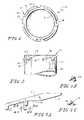
- FIG. 4illustrates a top view of a closure according to an exemplary embodiment of the present invention.
- FIG. 5illustrates a side, cross-sectional view of a closure including lugs according to an exemplary embodiment of the present invention.
- FIG. 6illustrates a side, cross-sectional view of lugs from a closure engaging a projection from a container according to an exemplary embodiment of the present invention.
- FIG. 7illustrates a side, cross-sectional view of a projection on a container neck engaging lugs of a closure according to an exemplary embodiment of the present invention.
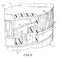
- FIG. 8illustrates a partial cut-away view of a closure on a container neck and showing lugs engaging a projection according to an exemplary embodiment of the present invention.
- FIG. 9illustrates a partial cut-away view of a closure according to another exemplary embodiment of the present invention.
- FIG. 10illustrates a side view of a container according to the exemplary embodiment of the present invention shown in FIG. 9 .
- FIG. 1illustrates an exemplary embodiment of container 10 .
- Container 10includes projections 12 arranged circumferentially around the outside of neck 18 of a sidewall. Four projections 12 are shown in FIG. 1 , though alternatively, more or fewer projections 12 may be provided.
- the sidewalldefines an interior 11 of container 10 .
- Projections 12each include ramp 13 , clamping surface 14 , cam surface 15 , and lock surface 16 . Projections 12 define locking area 17 .
- FIG. 2illustrates a side view of container 10 from FIG. 1 .
- FIG. 2shows neck 18 of sidewall 21 , as well as two projections 12 .
- Projections 12each include ramp 13 , clamping surface 14 , cam surface 15 , and lock surface 16 .
- Projections 12define locking area 17 .
- stop 20 of projections 12is also shown in FIG. 2 .
- FIG. 3 aillustrates an enlarged side view of projection 12 from FIGS. 1 and 2 .
- Projection 12includes ramp 13 and clamping surface 14 .
- Locking area 17is provided by projection 12 .
- FIG. 3 billustrates a cross-sectional view of the projection of FIG. 3 a taken along line IIIB—IIIB.
- FIG. 3 billustrates the profile of stop 20 , which is rectangular shaped.
- FIG. 3 cillustrates a cross-sectional view of the projection of FIG. 3 a taken along line IIIC—IIIC.
- FIG. 3 cillustrates the profile of cam surface 15 in relation to the profile of lock surface 16 .
- FIG. 4illustrates a top view of closure 40 including closure plane 41 .
- pairs of lugs 42Arranged circumferentially and evenly spaced around the outside edge of closure 40 are pairs of lugs 42 .
- Four pairs of lugs 42are shown in FIG. 4 , though more or fewer pairs of lugs 42 are possible.
- the number of pairs of lugs 42may be the same as the number of projections on the corresponding container.
- Each pair of lugs 42includes one lock lug 43 and one sealing lug 44 .
- Closure plane 41may include openings at or adjacent to one of lock lug 43 and sealing lug 44 . Alternatively, closure plane 41 may be substantially continuous without any openings.
- FIG. 5illustrates a side, cross-sectional view of closure 40 including lock lugs 43 and sealing lugs 44 .
- Each sealing lug 44is arranged on an inner sidewall of outer skirt 50 .
- Each lock lug 43is arranged on an inner sidewall of tamper-evident band 51 .
- Tamper evident band 51is attached to an edge of outer skirt 50 away from closure plane 41 by breakable connector 52 , which may be for instance a notch knife cut.
- Sealing lug 44 and lock lug 43 near the center line of FIG. 5are from different pairs of lugs. Specifically, sealing lug 44 near the center line of FIG. 5 is from a pair of lugs arranged on the distant side of outer skirt 50 , while lock lug 43 is from a pair of lugs arranged on the near side of outer skirt 50 .
- FIG. 6illustrates a side view of sealing lug 44 and lock lug 43 engaging projection 12 in a position after initial application of the closure to the container.
- the closurehas been applied to the container by tightening in a clockwise direction.
- sealing lug 44contacts ramp 13 causing the closure to seal the container and then contacts clamping surface 14 until sealing lug 44 contacts stop 20 .
- lock lug 43contacts cam surface 15 and is cammed over projection 12 into locking area 17 .
- Lock lug 43is prevented from moving in a counter-clockwise direction by lock surface 16 .
- the engagement between lock lug 43 and lock surface 16prevents the removal of the closure until the tamper-evident band is removed.
- FIG. 7illustrates a cross-sectional view of closure 40 showing closure plane 41 , outer skirt 50 , and tamper-evident band 51 .
- On the inside wall of outer skirt 50is sealing lug 44 , and on the inside wall of tamper-evident band 51 is lock lug 43 .
- FIG. 8illustrates a partial cut-away view of closure 40 on container 10 .
- Closure 40includes lock lug 43 , sealing lug 44 , closure plane 41 , outer skirt 50 , and tamper-evident band 51 .
- Sealing lug 44 and lock lug 43 of closure 40engage projection 12 of container 10 .
- Closure 40has been applied to container 10 by tightening in a clockwise direction.
- sealing lug 44contacts clamping surface 14 and stop 20 .
- lock lug 43has cammed over cam surface 15 and is in locking area 17 . Lock lug 43 is prevented from moving in a counter-clockwise direction by lock surface 16 .
- lock lug 43 and lock surface 16prevents the removal of closure 40 until tamper-evident band 51 is removed.
- the engagement between lock lug 43 and lock surface 16 when a counter-clockwise force applied to closure 40causes breakable connector 52 to shear, thereby causing tamper-evident band 51 to separate from outer skirt 50 .
- FIG. 9illustrates a partial cut-away view of closure 40 in another exemplary embodiment of the present invention.
- Closure 40includes lock lug 43 , sealing lug 44 , closure plane 41 , outer skirt 50 , and tamper-evident band 51 .
- closure 40includes inner wall 90 , which circumferentially extends from closure plane 41 in the same direction as outer skirt 50 .
- Inner wall 90is arranged radially inward from outer skirt 50 .
- FIG. 10illustrates a side view of container 10 cooperable with the exemplary embodiment of the closure shown in FIG. 9 .
- Container 10includes sidewall 21 including neck 18 .
- Tapered biasing surface 100tapers radially inward towards the edge of neck 18 .
- Tapered biasing surface 100is adapted to engage with an inner wall of a closure to bias the closure open.
- Tapered biasing surface 100may taper radially inwards, in which an outside diameter of neck 18 is smaller at the top edge than away from the edge. This type of taper for tapered biasing surface 100 is adapted to engage with an inner wall that lies on a radius on the closure of equal or greater size than the radius of the top edge of tapered biasing surface 100 .
- the inner wall of the closurecontacts tapered biasing surface 100 on a radially outside surface.
- the inner wall and/or tapered biasing surface 100deform as pressure is applied to close the closure on container 10 .
- the reaction against this deformation by the inner wall and/or tapered biasing surface 100causes the biasing open of the closure with respect to container 10 .
- tapered biasing surface 100may taper radially outward toward the edge of neck 18 , and therefore an inside radius of neck 18 may be larger at the top edge than away from the edge.
- This type of taper for tapered biasing surface 100is adapted to engage with an inner wall that lies on an inner radius on the closure. Therefore, when the closure is applied to container 10 , the inner wall of the closure contacts tapered biasing surface 100 on a radially inside surface.
- neck 18may or may not be tapered, and the inner wall of the closure is tapered.
- the inner wall of the closuremay be tapered inward or outward, and the inner wall may lie radially inwards or radially outwards, respectively.
- the engagement of the inner wall and neck 18may provide the appropriate biasing of the closure with respect to the container.
- FIG. 10illustrates an alternative embodiment of projection 12 .
- Projection 12 of FIG. 10includes child-resistant lock surface 101 and steep ramp 102 .
- Steep ramp 102engages with a sealing lug of a closure when the closure is being applied to container 10 .
- the engagement between steep ramp 102 and a sealing lugis opposed by the interaction between tapered biasing surface 100 and the inner wall of the closure. If the closure continues to be turned in the clockwise direction as the sealing lug reaches the end of steep ramp 102 , the sealing lug passes onto sealing surface 14 . Because sealing surface 14 is positioned closer to the top edge of neck 18 (tapered biasing surface 100 ), the closure then releases slightly the mutual deformation of tapered biasing surface 100 and the inner wall.
- Tapered biasing surface 100continues to contact the inner wall of the closure to cause a bias (and possibly a seal) in this position.
- the area between the edge of steep ramp 102 and sealing surface 14forms child resistant lock surface 101 .
- Child resistant lock surface 101prevents the removal of the closure from container 10 by simply turning in a counter-clockwise direction.
- a downward force on the closure with respect to container 10is required to oppose the biasing of tapered biasing surface 100 and the inner wall of the closure. Sufficient downward force is required to oppose this biasing to move the sealing lug below the lowest point of child resistant lock surface 101 .
- Child resistant lock surface 101no longer prevents counter-clockwise movement of the closure with respect to container 10 . Therefore, the closure can be removed by rotating it counter-clockwise. After moving the closure a distance in the counter-clockwise direction in order to position the sealing lug on steep ramp 102 , the downward force opposing the biasing of the tapered biasing surface 100 and the inner wall of the closure may be maintained, reduced, or eliminated. Continued turning in the counter-clockwise direction removes the closure from container 10 .
- Projection 12 of FIG. 10also includes stop 20 , cam surface 15 , and lock surface 16 , which operate in a similar manner to that described above. Specifically, the tamper-evident band of the closure prevents the movement of the closure on container 10 after the initial positioning of the closure on container 10 until the shear forces between the tamper-evident band and the outer skirt break the breakable connectors.
Landscapes
- Engineering & Computer Science (AREA)
- Mechanical Engineering (AREA)
- Closures For Containers (AREA)
Abstract
Description
Claims (17)
Priority Applications (3)
| Application Number | Priority Date | Filing Date | Title |
|---|---|---|---|
| US10/753,850US7198170B2 (en) | 2004-01-07 | 2004-01-07 | Closure and container system and method for sealing a closure on a container |
| CA2551717ACA2551717C (en) | 2004-01-07 | 2005-01-07 | Closure and container system and method for sealing a closure on a container |
| PCT/US2005/000362WO2005067616A2 (en) | 2004-01-07 | 2005-01-07 | Closure and container system and method |
Applications Claiming Priority (1)
| Application Number | Priority Date | Filing Date | Title |
|---|---|---|---|
| US10/753,850US7198170B2 (en) | 2004-01-07 | 2004-01-07 | Closure and container system and method for sealing a closure on a container |
Publications (2)
| Publication Number | Publication Date |
|---|---|
| US20050145629A1 US20050145629A1 (en) | 2005-07-07 |
| US7198170B2true US7198170B2 (en) | 2007-04-03 |
Family
ID=34711784
Family Applications (1)
| Application Number | Title | Priority Date | Filing Date |
|---|---|---|---|
| US10/753,850Expired - Fee RelatedUS7198170B2 (en) | 2004-01-07 | 2004-01-07 | Closure and container system and method for sealing a closure on a container |
Country Status (3)
| Country | Link |
|---|---|
| US (1) | US7198170B2 (en) |
| CA (1) | CA2551717C (en) |
| WO (1) | WO2005067616A2 (en) |
Cited By (22)
| Publication number | Priority date | Publication date | Assignee | Title |
|---|---|---|---|---|
| US20060273061A1 (en)* | 2005-06-06 | 2006-12-07 | Mark Fricke | Method and device for a child resistant dropper closure |
| US20070012645A1 (en)* | 2005-07-14 | 2007-01-18 | Owens-Illinois Prescription Products Inc. | Child-resistant closure, package and method of making |
| US20090057260A1 (en)* | 2007-08-27 | 2009-03-05 | Sunil Mohindra | Tamper-Evident Container |
| US20100162900A1 (en)* | 2006-08-14 | 2010-07-01 | Koninklijke Philips Electronics N.V. | Beverage make comprising a pad holder which can be connected to a brew chamber top portion through a bayonet connection |
| US20110011947A1 (en)* | 2009-07-14 | 2011-01-20 | The Dial Corporation | Gel air freshener and method of unsealing such gel air freshener |
| USD671834S1 (en) | 2011-01-07 | 2012-12-04 | Ball Corporation | Closure |
| US20130087573A1 (en)* | 2010-03-23 | 2013-04-11 | Superfos A/S | Container |
| US8424695B2 (en) | 2011-06-22 | 2013-04-23 | Van Blarcom Closures, Inc. | Spring action child resistant closure and container |
| US8708176B2 (en) | 2009-12-30 | 2014-04-29 | Tim Andis | Quick access closure apparatus and methods of use |
| US8720717B2 (en) | 2012-02-02 | 2014-05-13 | Ball Corporation | End closure with full panel opening |
| US8925755B2 (en) | 2010-04-13 | 2015-01-06 | Ipl, Inc. | Tamper evident system and method |
| US9901972B2 (en) | 2014-03-07 | 2018-02-27 | Ball Corporation | End closure with large opening ring pull tab |
| USRE47156E1 (en)* | 2008-04-30 | 2018-12-11 | Closure Systems International Inc. | Tamper-evident bottle and closure having vents |
| US10322853B2 (en)* | 2016-11-30 | 2019-06-18 | General Electric Company | Apparatus and method for securing a vessel |
| US10632520B2 (en) | 2014-03-07 | 2020-04-28 | Ball Corporation | End closure with large opening ring pull tab |
| US20210129384A1 (en)* | 2010-12-17 | 2021-05-06 | Dispensing Technologies B.V. | Preforms for flair applications |
| US11059633B2 (en) | 2019-10-31 | 2021-07-13 | Cheer Pack North America | Flip-top closure for container |
| US11124335B1 (en)* | 2020-04-23 | 2021-09-21 | Frederick Mahan | Auto lock lid |
| US20230211928A1 (en)* | 2021-09-15 | 2023-07-06 | Mike C. Sanchez | Child-resistant container and closure |
| USD1092136S1 (en) | 2023-11-13 | 2025-09-09 | Yeti Coolers, Llc | Lid for a beverage maker |
| USD1093081S1 (en) | 2023-11-13 | 2025-09-16 | Yeti Coolers, Llc | Beverage maker |
| USD1093980S1 (en) | 2023-11-13 | 2025-09-23 | Yeti Coolers, Llc | Beverage maker |
Families Citing this family (13)
| Publication number | Priority date | Publication date | Assignee | Title |
|---|---|---|---|---|
| US7691129B2 (en) | 2004-10-27 | 2010-04-06 | Felix Brent A | Spinal stabilizing system |
| US7510094B1 (en)* | 2005-01-04 | 2009-03-31 | Rexam Closures And Containers Inc. | Child resistant one piece push and turn closure |
| US20080001741A1 (en)* | 2006-06-29 | 2008-01-03 | Honeywell International Inc. | Large area distributed sensor |
| US8016862B2 (en)* | 2006-09-27 | 2011-09-13 | Innovasis, Inc. | Spinal stabilizing system |
| US20080223807A1 (en)* | 2007-03-15 | 2008-09-18 | Blaine Company, Inc. D/B/A Blaine Pharmaceutical | Collar for liquid and medicine dispensing bottle |
| US7755489B2 (en) | 2008-04-28 | 2010-07-13 | Honeywell International Inc. | Intelligent packaging method and system based on acoustic wave devices |
| JP4872011B2 (en)* | 2010-07-15 | 2012-02-08 | 株式会社エフピコ | Container with lid |
| MX2011002176A (en)* | 2011-02-25 | 2012-08-30 | Tricorbraun S De R L De C V | ¼ turn closing system for a container. |
| JP5755020B2 (en)* | 2011-05-12 | 2015-07-29 | キャニヨン株式会社 | Bayonet connection structure between container mouth and cap |
| CA2815936A1 (en)* | 2013-03-14 | 2014-09-14 | Stryker Corporation | Tamper-evident camera enclosure |
| TWM465084U (en)* | 2013-07-09 | 2013-11-11 | Lion Pencil Co Ltd | Chair with storage function |
| US20180332892A1 (en)* | 2017-05-17 | 2018-11-22 | Smoke Spot, Llc | Container for Cannabis and Tobacco |
| US10961031B2 (en) | 2018-12-24 | 2021-03-30 | Target Brands, Inc. | Container assembly with locking closure |
Citations (51)
| Publication number | Priority date | Publication date | Assignee | Title |
|---|---|---|---|---|
| US801283A (en) | 1904-11-18 | 1905-10-10 | Alfred L Weissenthanner | Sheet-metal stopper. |
| US1683388A (en) | 1927-11-07 | 1928-09-04 | American Metal Cap Co | Combined lug cap and liner plate |
| US2000407A (en) | 1933-06-29 | 1935-05-07 | Frankfort Distilleries Inc | Bottle and closure therefor |
| US3165220A (en) | 1962-01-22 | 1965-01-12 | Don A Haynes | Tamper-proof container |
| US3197055A (en) | 1963-07-09 | 1965-07-27 | Aluminum Co Of America | Plastic container, metallic closure packaging |
| US3460703A (en) | 1967-07-18 | 1969-08-12 | Aluminum Co Of America | Container and closure |
| US3692200A (en) | 1969-11-11 | 1972-09-19 | Seidel Kg Geb | Container and closure cap assembly |
| US3913772A (en) | 1973-09-14 | 1975-10-21 | Anchor Hocking Corp | Tamperproof closure cap and sealed package |
| US4190169A (en) | 1979-01-15 | 1980-02-26 | Pehr Harold T | Tamperproof package |
| US4241842A (en) | 1979-08-06 | 1980-12-30 | Toeppen Thurston H | Tamper indicating construction for plastic closures |
| GB2096110A (en) | 1981-04-02 | 1982-10-13 | Anchor Hocking Corp | Tamper-indicating bottle closure cap |
| US4378894A (en) | 1981-06-19 | 1983-04-05 | Aluminum Company Of America | Tamper-evident closure |
| US4380299A (en) | 1980-09-10 | 1983-04-19 | Precision Plastic Products Corporation | Tamper proof closure |
| US4448318A (en) | 1982-08-20 | 1984-05-15 | The West Company | Tamper evident container-closure assembly |
| GB2148259A (en) | 1983-10-19 | 1985-05-30 | Anchor Hocking Corp | A tamper-indicating child-resistant closure |
| US4530438A (en) | 1985-05-04 | 1985-07-23 | Owens-Illinois, Inc. | Tamper indicating packages |
| US4534480A (en) | 1984-06-01 | 1985-08-13 | Sun Coast Plastics, Inc. | Tamper evident closure |
| US4547332A (en) | 1983-03-17 | 1985-10-15 | Captive Plastics, Inc. | Method of forming tamper evident closures |
| US4560076A (en) | 1984-04-17 | 1985-12-24 | Continental White Cap, Inc. | Tamper indicating band for use in low rise cam-off application |
| US4567991A (en) | 1984-10-12 | 1986-02-04 | Sunbeam Plastics Corporation | Tamper indicating child resistant closure |
| US4700860A (en) | 1986-03-31 | 1987-10-20 | Owens-Illinois, Inc. | Tamper indicating vacuum package |
| US4709830A (en) | 1987-04-16 | 1987-12-01 | Courtesy Mold & Tool Corporation | Closure with top cut tamper evident feature for wide mouth container |
| US4828127A (en) | 1987-03-04 | 1989-05-09 | Cope Allman Plastics Limited | Tamper-evident closures |
| DE3842443A1 (en) | 1987-12-16 | 1989-08-10 | Norbert Barein | Tamper-indicating closure |
| US4875594A (en) | 1988-12-16 | 1989-10-24 | Anchor Hocking Corporation | Closure cap |
| EP0341949A1 (en) | 1988-05-12 | 1989-11-15 | Cap Snap Co. | Tamper-evident container cap having sealed disc retention means |
| US4923073A (en) | 1989-01-30 | 1990-05-08 | H-C Industries, Inc. | Tamper-indicating plastic closure |
| US4936475A (en) | 1988-09-19 | 1990-06-26 | Sunbeam Plastics Corporation | Threaded tamper indicating closure |
| US5009323A (en) | 1989-11-13 | 1991-04-23 | Sunbeam Plastics Corporation | Tamper indicating closure having a rotary seal |
| US5174465A (en) | 1991-03-05 | 1992-12-29 | Cap Snap Co. | One-piece fitment and cap with tamper-evident band |
| US5307946A (en) | 1993-03-24 | 1994-05-03 | Northern Engineering & Plastics, Corp. | Neck finish for a container and a matching registering multiple thread pattern in a flexible cap for engagement on neck said finish |
| US5307945A (en) | 1992-06-26 | 1994-05-03 | Hidding Walter E | Closure |
| US5320233A (en) | 1993-08-30 | 1994-06-14 | Aluminum Company Of America | Tamper evident lug cap |
| US5341947A (en) | 1990-09-12 | 1994-08-30 | Nestec S.A. | Tamper-evident device for container closures |
| US5449078A (en) | 1994-07-08 | 1995-09-12 | Thermar Corporation | Combination of a container and a safety cap therefor |
| US5450972A (en) | 1994-03-03 | 1995-09-19 | Phoenix Closures, Inc. | Tamper-evident band for closures |
| US5685445A (en) | 1995-06-14 | 1997-11-11 | Calmar Inc. | Anti-backoff removable closure for connecting a manually actuated liquid dispenser to a container |
| US5749484A (en) | 1995-09-22 | 1998-05-12 | Rieke Corporation | Tamper-evident child-resistant closure |
| US5829613A (en) | 1995-08-21 | 1998-11-03 | Superseal Corporation | Snap-on/screw-off cap and neck configuration |
| US5894124A (en) | 1995-03-17 | 1999-04-13 | Hitachi, Ltd. | Scanning electron microscope and its analogous device |
| US5927532A (en) | 1997-04-21 | 1999-07-27 | Owens-Illinois Closure Inc. | Vapor-seal child resistant closure and container package |
| US5950850A (en)* | 1996-05-14 | 1999-09-14 | Shibazaki Seisakusho, Ltd. | Sealing device and container |
| US6015054A (en)* | 1995-12-08 | 2000-01-18 | Beeson And Sons Limited | Container closure assembly with profiled screw threads |
| US6056136A (en) | 1995-11-30 | 2000-05-02 | White Cap, Inc. | Lug closure for press-on application to, and rotational removal from, a threaded neck container |
| US6085921A (en) | 1998-02-26 | 2000-07-11 | Crown Cork & Seal Technologies Corporation | Tamper evident band with undercut |
| US6119883A (en) | 1998-12-07 | 2000-09-19 | Owens-Illinois Closure Inc. | Tamper-indicating closure and method of manufacture |
| US6305579B1 (en) | 1997-10-30 | 2001-10-23 | International Plastics And Equipment Corporation | Snap-on screw-off closure |
| US20020033374A1 (en) | 1997-08-01 | 2002-03-21 | Ma Mike Xiaoli | Tamper evidencing closure |
| US6382444B1 (en) | 1999-03-17 | 2002-05-07 | Sentinel Packaging Systems, Inc. | Tamper-evident plastic closure system with snap-on band |
| US20020062626A1 (en) | 1999-04-28 | 2002-05-30 | Gregory James L. | Tamper-indicating closure with lugs on a stop flange for spacing the flange from the finish of a container |
| US20030071007A1 (en) | 1997-08-01 | 2003-04-17 | Ma Mike Xiaoli | Tamper evident bottle cap |
Family Cites Families (1)
| Publication number | Priority date | Publication date | Assignee | Title |
|---|---|---|---|---|
| US201283A (en)* | 1878-03-12 | Improvement in compositions for crayons |
- 2004
- 2004-01-07USUS10/753,850patent/US7198170B2/ennot_activeExpired - Fee Related
- 2005
- 2005-01-07CACA2551717Apatent/CA2551717C/ennot_activeExpired - Fee Related
- 2005-01-07WOPCT/US2005/000362patent/WO2005067616A2/enactiveApplication Filing
Patent Citations (51)
| Publication number | Priority date | Publication date | Assignee | Title |
|---|---|---|---|---|
| US801283A (en) | 1904-11-18 | 1905-10-10 | Alfred L Weissenthanner | Sheet-metal stopper. |
| US1683388A (en) | 1927-11-07 | 1928-09-04 | American Metal Cap Co | Combined lug cap and liner plate |
| US2000407A (en) | 1933-06-29 | 1935-05-07 | Frankfort Distilleries Inc | Bottle and closure therefor |
| US3165220A (en) | 1962-01-22 | 1965-01-12 | Don A Haynes | Tamper-proof container |
| US3197055A (en) | 1963-07-09 | 1965-07-27 | Aluminum Co Of America | Plastic container, metallic closure packaging |
| US3460703A (en) | 1967-07-18 | 1969-08-12 | Aluminum Co Of America | Container and closure |
| US3692200A (en) | 1969-11-11 | 1972-09-19 | Seidel Kg Geb | Container and closure cap assembly |
| US3913772A (en) | 1973-09-14 | 1975-10-21 | Anchor Hocking Corp | Tamperproof closure cap and sealed package |
| US4190169A (en) | 1979-01-15 | 1980-02-26 | Pehr Harold T | Tamperproof package |
| US4241842A (en) | 1979-08-06 | 1980-12-30 | Toeppen Thurston H | Tamper indicating construction for plastic closures |
| US4380299A (en) | 1980-09-10 | 1983-04-19 | Precision Plastic Products Corporation | Tamper proof closure |
| GB2096110A (en) | 1981-04-02 | 1982-10-13 | Anchor Hocking Corp | Tamper-indicating bottle closure cap |
| US4378894A (en) | 1981-06-19 | 1983-04-05 | Aluminum Company Of America | Tamper-evident closure |
| US4448318A (en) | 1982-08-20 | 1984-05-15 | The West Company | Tamper evident container-closure assembly |
| US4547332A (en) | 1983-03-17 | 1985-10-15 | Captive Plastics, Inc. | Method of forming tamper evident closures |
| GB2148259A (en) | 1983-10-19 | 1985-05-30 | Anchor Hocking Corp | A tamper-indicating child-resistant closure |
| US4560076A (en) | 1984-04-17 | 1985-12-24 | Continental White Cap, Inc. | Tamper indicating band for use in low rise cam-off application |
| US4534480A (en) | 1984-06-01 | 1985-08-13 | Sun Coast Plastics, Inc. | Tamper evident closure |
| US4567991A (en) | 1984-10-12 | 1986-02-04 | Sunbeam Plastics Corporation | Tamper indicating child resistant closure |
| US4530438A (en) | 1985-05-04 | 1985-07-23 | Owens-Illinois, Inc. | Tamper indicating packages |
| US4700860A (en) | 1986-03-31 | 1987-10-20 | Owens-Illinois, Inc. | Tamper indicating vacuum package |
| US4828127A (en) | 1987-03-04 | 1989-05-09 | Cope Allman Plastics Limited | Tamper-evident closures |
| US4709830A (en) | 1987-04-16 | 1987-12-01 | Courtesy Mold & Tool Corporation | Closure with top cut tamper evident feature for wide mouth container |
| DE3842443A1 (en) | 1987-12-16 | 1989-08-10 | Norbert Barein | Tamper-indicating closure |
| EP0341949A1 (en) | 1988-05-12 | 1989-11-15 | Cap Snap Co. | Tamper-evident container cap having sealed disc retention means |
| US4936475A (en) | 1988-09-19 | 1990-06-26 | Sunbeam Plastics Corporation | Threaded tamper indicating closure |
| US4875594A (en) | 1988-12-16 | 1989-10-24 | Anchor Hocking Corporation | Closure cap |
| US4923073A (en) | 1989-01-30 | 1990-05-08 | H-C Industries, Inc. | Tamper-indicating plastic closure |
| US5009323A (en) | 1989-11-13 | 1991-04-23 | Sunbeam Plastics Corporation | Tamper indicating closure having a rotary seal |
| US5341947A (en) | 1990-09-12 | 1994-08-30 | Nestec S.A. | Tamper-evident device for container closures |
| US5174465A (en) | 1991-03-05 | 1992-12-29 | Cap Snap Co. | One-piece fitment and cap with tamper-evident band |
| US5307945A (en) | 1992-06-26 | 1994-05-03 | Hidding Walter E | Closure |
| US5307946A (en) | 1993-03-24 | 1994-05-03 | Northern Engineering & Plastics, Corp. | Neck finish for a container and a matching registering multiple thread pattern in a flexible cap for engagement on neck said finish |
| US5320233A (en) | 1993-08-30 | 1994-06-14 | Aluminum Company Of America | Tamper evident lug cap |
| US5450972A (en) | 1994-03-03 | 1995-09-19 | Phoenix Closures, Inc. | Tamper-evident band for closures |
| US5449078A (en) | 1994-07-08 | 1995-09-12 | Thermar Corporation | Combination of a container and a safety cap therefor |
| US5894124A (en) | 1995-03-17 | 1999-04-13 | Hitachi, Ltd. | Scanning electron microscope and its analogous device |
| US5685445A (en) | 1995-06-14 | 1997-11-11 | Calmar Inc. | Anti-backoff removable closure for connecting a manually actuated liquid dispenser to a container |
| US5829613A (en) | 1995-08-21 | 1998-11-03 | Superseal Corporation | Snap-on/screw-off cap and neck configuration |
| US5749484A (en) | 1995-09-22 | 1998-05-12 | Rieke Corporation | Tamper-evident child-resistant closure |
| US6056136A (en) | 1995-11-30 | 2000-05-02 | White Cap, Inc. | Lug closure for press-on application to, and rotational removal from, a threaded neck container |
| US6015054A (en)* | 1995-12-08 | 2000-01-18 | Beeson And Sons Limited | Container closure assembly with profiled screw threads |
| US5950850A (en)* | 1996-05-14 | 1999-09-14 | Shibazaki Seisakusho, Ltd. | Sealing device and container |
| US5927532A (en) | 1997-04-21 | 1999-07-27 | Owens-Illinois Closure Inc. | Vapor-seal child resistant closure and container package |
| US20020033374A1 (en) | 1997-08-01 | 2002-03-21 | Ma Mike Xiaoli | Tamper evidencing closure |
| US20030071007A1 (en) | 1997-08-01 | 2003-04-17 | Ma Mike Xiaoli | Tamper evident bottle cap |
| US6305579B1 (en) | 1997-10-30 | 2001-10-23 | International Plastics And Equipment Corporation | Snap-on screw-off closure |
| US6085921A (en) | 1998-02-26 | 2000-07-11 | Crown Cork & Seal Technologies Corporation | Tamper evident band with undercut |
| US6119883A (en) | 1998-12-07 | 2000-09-19 | Owens-Illinois Closure Inc. | Tamper-indicating closure and method of manufacture |
| US6382444B1 (en) | 1999-03-17 | 2002-05-07 | Sentinel Packaging Systems, Inc. | Tamper-evident plastic closure system with snap-on band |
| US20020062626A1 (en) | 1999-04-28 | 2002-05-30 | Gregory James L. | Tamper-indicating closure with lugs on a stop flange for spacing the flange from the finish of a container |
Cited By (25)
| Publication number | Priority date | Publication date | Assignee | Title |
|---|---|---|---|---|
| US20060273061A1 (en)* | 2005-06-06 | 2006-12-07 | Mark Fricke | Method and device for a child resistant dropper closure |
| US20070012645A1 (en)* | 2005-07-14 | 2007-01-18 | Owens-Illinois Prescription Products Inc. | Child-resistant closure, package and method of making |
| US8132684B2 (en)* | 2005-07-14 | 2012-03-13 | Rexam Prescription Products Inc. | Child-resistant closure, package and method of making |
| US20100162900A1 (en)* | 2006-08-14 | 2010-07-01 | Koninklijke Philips Electronics N.V. | Beverage make comprising a pad holder which can be connected to a brew chamber top portion through a bayonet connection |
| US20090057260A1 (en)* | 2007-08-27 | 2009-03-05 | Sunil Mohindra | Tamper-Evident Container |
| USRE47156E1 (en)* | 2008-04-30 | 2018-12-11 | Closure Systems International Inc. | Tamper-evident bottle and closure having vents |
| US20110011947A1 (en)* | 2009-07-14 | 2011-01-20 | The Dial Corporation | Gel air freshener and method of unsealing such gel air freshener |
| US8141793B2 (en) | 2009-07-14 | 2012-03-27 | The Dial Corporation | Gel air freshener and method of unsealing such gel air freshener |
| US8708176B2 (en) | 2009-12-30 | 2014-04-29 | Tim Andis | Quick access closure apparatus and methods of use |
| US20130087573A1 (en)* | 2010-03-23 | 2013-04-11 | Superfos A/S | Container |
| US9056698B2 (en)* | 2010-03-23 | 2015-06-16 | Superfos A/S | Container |
| US8925755B2 (en) | 2010-04-13 | 2015-01-06 | Ipl, Inc. | Tamper evident system and method |
| US20210129384A1 (en)* | 2010-12-17 | 2021-05-06 | Dispensing Technologies B.V. | Preforms for flair applications |
| USD671834S1 (en) | 2011-01-07 | 2012-12-04 | Ball Corporation | Closure |
| US8424695B2 (en) | 2011-06-22 | 2013-04-23 | Van Blarcom Closures, Inc. | Spring action child resistant closure and container |
| US8720717B2 (en) | 2012-02-02 | 2014-05-13 | Ball Corporation | End closure with full panel opening |
| US9901972B2 (en) | 2014-03-07 | 2018-02-27 | Ball Corporation | End closure with large opening ring pull tab |
| US10632520B2 (en) | 2014-03-07 | 2020-04-28 | Ball Corporation | End closure with large opening ring pull tab |
| US10322853B2 (en)* | 2016-11-30 | 2019-06-18 | General Electric Company | Apparatus and method for securing a vessel |
| US11059633B2 (en) | 2019-10-31 | 2021-07-13 | Cheer Pack North America | Flip-top closure for container |
| US11124335B1 (en)* | 2020-04-23 | 2021-09-21 | Frederick Mahan | Auto lock lid |
| US20230211928A1 (en)* | 2021-09-15 | 2023-07-06 | Mike C. Sanchez | Child-resistant container and closure |
| USD1092136S1 (en) | 2023-11-13 | 2025-09-09 | Yeti Coolers, Llc | Lid for a beverage maker |
| USD1093081S1 (en) | 2023-11-13 | 2025-09-16 | Yeti Coolers, Llc | Beverage maker |
| USD1093980S1 (en) | 2023-11-13 | 2025-09-23 | Yeti Coolers, Llc | Beverage maker |
Also Published As
| Publication number | Publication date |
|---|---|
| WO2005067616A2 (en) | 2005-07-28 |
| CA2551717C (en) | 2010-06-22 |
| CA2551717A1 (en) | 2005-07-28 |
| US20050145629A1 (en) | 2005-07-07 |
| WO2005067616A3 (en) | 2006-09-08 |
Similar Documents
| Publication | Publication Date | Title |
|---|---|---|
| US7198170B2 (en) | Closure and container system and method for sealing a closure on a container | |
| US10315808B2 (en) | Container closure cap and container closure | |
| US4534481A (en) | Snap-on, tamper-evident container closure | |
| US7549547B2 (en) | Composite two-piece tamper-evident closure with a seal-delay-release feature and a method therefor | |
| US5450973A (en) | Tamper-evident closure apparatus | |
| US4196818A (en) | Closures for containers | |
| US4938370A (en) | Tamper-indicating plastic closure | |
| US4190169A (en) | Tamperproof package | |
| US6039196A (en) | Tamper indicating child-resistant closure | |
| AU649929B2 (en) | Tamper proof cap and container | |
| US5137163A (en) | Tamper evident closure with ramped contact | |
| AU2003302391B2 (en) | Tamper evident closure with locking band | |
| US4572385A (en) | Tamper indicating child resistant threaded closure | |
| US4503986A (en) | Tamper-evident closure cap | |
| US4276988A (en) | Tamper-proof closure | |
| US4341318A (en) | Closure with child-resistant tamper-proof band | |
| US5971182A (en) | Closure with tamper-evident band | |
| EP1673286B1 (en) | Closure having user-modifiable functionality | |
| JP4866358B2 (en) | Tamper-evident opening package for children | |
| EP0213742A2 (en) | Tamper indicating closure member for containers | |
| JP2002002744A (en) | Tamper evident container | |
| CZ9901190A3 (en) | Screw-type cap with safety and guarantee band | |
| EP3649055A1 (en) | Tamper-evident closure and container provided with the same | |
| GB2344102A (en) | Tamper evident closure device | |
| JP3106332B2 (en) | Synthetic resin container lid |
Legal Events
| Date | Code | Title | Description |
|---|---|---|---|
| AS | Assignment | Owner name:KERR GROUP, INC., PENNSYLVANIA Free format text:ASSIGNMENT OF ASSIGNORS INTEREST;ASSIGNOR:HERR, JAMES E.;REEL/FRAME:014882/0584 Effective date:20040105 | |
| AS | Assignment | Owner name:DEUTSCHE BANK TRUST COMPANY AMERICAS, AS COLLATERA Free format text:SECURITY AGREEMENT;ASSIGNOR:KERR GROUP INC.;REEL/FRAME:016164/0188 Effective date:20050603 | |
| AS | Assignment | Owner name:BERRY PLASTICS CORPORATION, INDIANA Free format text:ASSIGNMENT OF ASSIGNORS INTEREST;ASSIGNOR:KERR GROUP, INC.;REEL/FRAME:017853/0072 Effective date:20060623 | |
| AS | Assignment | Owner name:CREDIT SUISSE, AS ADMINISTRATIVE AGENT,NEW YORK Free format text:SECURITY AGREEMENT;ASSIGNOR:BERRY PLASTICS CORPORATION;REEL/FRAME:018291/0155 Effective date:20060920 Owner name:CREDIT SUISSE, AS ADMINISTRATIVE AGENT, NEW YORK Free format text:SECURITY AGREEMENT;ASSIGNOR:BERRY PLASTICS CORPORATION;REEL/FRAME:018291/0155 Effective date:20060920 | |
| AS | Assignment | Owner name:WELLS FARGO BANK, N.A., AS COLLATERAL AGENT,CONNEC Free format text:SECOND LIEN PATENT SECURITY AGREEMENT;ASSIGNORS:BERRY PLASTICS CORPORATION;BERRY STERLING CORPORATION;KERR GROUP, INC.;AND OTHERS;REEL/FRAME:018407/0074 Effective date:20060920 Owner name:WELLS FARGO BANK, N.A., AS COLLATERAL AGENT, CONNE Free format text:SECOND LIEN PATENT SECURITY AGREEMENT;ASSIGNORS:BERRY PLASTICS CORPORATION;BERRY STERLING CORPORATION;KERR GROUP, INC.;AND OTHERS;REEL/FRAME:018407/0074 Effective date:20060920 | |
| AS | Assignment | Owner name:BERRY PLASTICS CORPORATION,INDIANA Free format text:RELEASE OF SECURITY INTEREST IN PATENT COLLATERAL (REEL/FRAME NO. 018291/0155);ASSIGNOR:CREDIT SUISSE, CAYMAN ISLANDS BRANCH;REEL/FRAME:019111/0266 Effective date:20070403 Owner name:BERRY PLASTICS CORPORATION, INDIANA Free format text:RELEASE OF SECURITY INTEREST IN PATENT COLLATERAL (REEL/FRAME NO. 018291/0155);ASSIGNOR:CREDIT SUISSE, CAYMAN ISLANDS BRANCH;REEL/FRAME:019111/0266 Effective date:20070403 | |
| AS | Assignment | Owner name:BANK OF AMERICA, N.A., AS ABL COLLATERAL AGENT,NOR Free format text:SECOND AMENDED AND RESTATED FIRST LIEN INTELLECTUAL PROPERTY SECURITY AGREEMENT;ASSIGNOR:BERRY PLASTICS HOLDING CORPORATION;REEL/FRAME:019147/0479 Effective date:20070403 Owner name:CREDIT SUISSE, CAYMAN ISLANDS BRANCH, AS TERM COLL Free format text:SECOND AMENDED AND RESTATED FIRST LIEN INTELLECTUAL PROPERTY SECURITY AGREEMENT;ASSIGNOR:BERRY PLASTICS HOLDING CORPORATION;REEL/FRAME:019147/0479 Effective date:20070403 Owner name:BANK OF AMERICA, N.A., AS ABL COLLATERAL AGENT, NO Free format text:SECOND AMENDED AND RESTATED FIRST LIEN INTELLECTUAL PROPERTY SECURITY AGREEMENT;ASSIGNOR:BERRY PLASTICS HOLDING CORPORATION;REEL/FRAME:019147/0479 Effective date:20070403 | |
| AS | Assignment | Owner name:BANK OF AMERICA, N.A., AS COLLATERAL AGENT, CALIFO Free format text:BRIDGE LOAN FIRST LIEN INTELLECTUAL PROPERTY SECURITY AGREEMENT;ASSIGNORS:BERRY PLASTICS CORPORATION;BERRY STERLING CORPORATION;CAPTIVE PLASTICS, INC.;AND OTHERS;REEL/FRAME:020638/0249 Effective date:20080205 Owner name:BANK OF AMERICA, N.A., AS COLLATERAL AGENT,CALIFOR Free format text:BRIDGE LOAN FIRST LIEN INTELLECTUAL PROPERTY SECURITY AGREEMENT;ASSIGNORS:BERRY PLASTICS CORPORATION;BERRY STERLING CORPORATION;CAPTIVE PLASTICS, INC.;AND OTHERS;REEL/FRAME:020638/0249 Effective date:20080205 | |
| AS | Assignment | Owner name:BERRY PLASTICS CORPORATION, INDIANA Free format text:RELEASE OF BRIDGE 1ST LIEN SECURITY AGREEMENT;ASSIGNOR:BANK OF AMERICA, N.A.;REEL/FRAME:020845/0198 Effective date:20080421 Owner name:BERRY STERLING CORPORATION, INDIANA Free format text:RELEASE OF BRIDGE 1ST LIEN SECURITY AGREEMENT;ASSIGNOR:BANK OF AMERICA, N.A.;REEL/FRAME:020845/0198 Effective date:20080421 Owner name:CAPTIVE PLASTICS, INC., NEW JERSEY Free format text:RELEASE OF BRIDGE 1ST LIEN SECURITY AGREEMENT;ASSIGNOR:BANK OF AMERICA, N.A.;REEL/FRAME:020845/0198 Effective date:20080421 Owner name:GRAFCO INDUSTRIES LIMITED PARTNERSHIP, NEW JERSEY Free format text:RELEASE OF BRIDGE 1ST LIEN SECURITY AGREEMENT;ASSIGNOR:BANK OF AMERICA, N.A.;REEL/FRAME:020845/0198 Effective date:20080421 Owner name:LANDIS PLASTICS, LLC, ILLINOIS Free format text:RELEASE OF BRIDGE 1ST LIEN SECURITY AGREEMENT;ASSIGNOR:BANK OF AMERICA, N.A.;REEL/FRAME:020845/0198 Effective date:20080421 Owner name:SETCO, LLC, CALIFORNIA Free format text:RELEASE OF BRIDGE 1ST LIEN SECURITY AGREEMENT;ASSIGNOR:BANK OF AMERICA, N.A.;REEL/FRAME:020845/0198 Effective date:20080421 Owner name:TUBED PRODUCTS, LLC, MASSACHUSETTS Free format text:RELEASE OF BRIDGE 1ST LIEN SECURITY AGREEMENT;ASSIGNOR:BANK OF AMERICA, N.A.;REEL/FRAME:020845/0198 Effective date:20080421 Owner name:WELLS FARGO BANK, N.A., CONNECTICUT Free format text:SECURITY AGREEMENT;ASSIGNORS:BERRY PLASTICS CORPORATION;BERRY STERLING CORPORATION;CAPTIVE PLASTICS, INC.;AND OTHERS;REEL/FRAME:020845/0301 Effective date:20080421 Owner name:BERRY PLASTICS CORPORATION,INDIANA Free format text:RELEASE OF BRIDGE 1ST LIEN SECURITY AGREEMENT;ASSIGNOR:BANK OF AMERICA, N.A.;REEL/FRAME:020845/0198 Effective date:20080421 Owner name:BERRY STERLING CORPORATION,INDIANA Free format text:RELEASE OF BRIDGE 1ST LIEN SECURITY AGREEMENT;ASSIGNOR:BANK OF AMERICA, N.A.;REEL/FRAME:020845/0198 Effective date:20080421 Owner name:CAPTIVE PLASTICS, INC.,NEW JERSEY Free format text:RELEASE OF BRIDGE 1ST LIEN SECURITY AGREEMENT;ASSIGNOR:BANK OF AMERICA, N.A.;REEL/FRAME:020845/0198 Effective date:20080421 Owner name:GRAFCO INDUSTRIES LIMITED PARTNERSHIP,NEW JERSEY Free format text:RELEASE OF BRIDGE 1ST LIEN SECURITY AGREEMENT;ASSIGNOR:BANK OF AMERICA, N.A.;REEL/FRAME:020845/0198 Effective date:20080421 Owner name:LANDIS PLASTICS, LLC,ILLINOIS Free format text:RELEASE OF BRIDGE 1ST LIEN SECURITY AGREEMENT;ASSIGNOR:BANK OF AMERICA, N.A.;REEL/FRAME:020845/0198 Effective date:20080421 Owner name:SETCO, LLC,CALIFORNIA Free format text:RELEASE OF BRIDGE 1ST LIEN SECURITY AGREEMENT;ASSIGNOR:BANK OF AMERICA, N.A.;REEL/FRAME:020845/0198 Effective date:20080421 Owner name:TUBED PRODUCTS, LLC,MASSACHUSETTS Free format text:RELEASE OF BRIDGE 1ST LIEN SECURITY AGREEMENT;ASSIGNOR:BANK OF AMERICA, N.A.;REEL/FRAME:020845/0198 Effective date:20080421 Owner name:WELLS FARGO BANK, N.A.,CONNECTICUT Free format text:SECURITY AGREEMENT;ASSIGNORS:BERRY PLASTICS CORPORATION;BERRY STERLING CORPORATION;CAPTIVE PLASTICS, INC.;AND OTHERS;REEL/FRAME:020845/0301 Effective date:20080421 | |
| AS | Assignment | Owner name:BERRY PLASTICS CORPORATION, INDIANA Free format text:RELEASE OF SECURITY INTEREST AT REEL 016164 FRAME 0188;ASSIGNOR:DEUTSCHE BANK TRUST COMPANY AMERICAS;REEL/FRAME:020866/0517 Effective date:20060920 | |
| FPAY | Fee payment | Year of fee payment:4 | |
| REMI | Maintenance fee reminder mailed | ||
| LAPS | Lapse for failure to pay maintenance fees | ||
| STCH | Information on status: patent discontinuation | Free format text:PATENT EXPIRED DUE TO NONPAYMENT OF MAINTENANCE FEES UNDER 37 CFR 1.362 | |
| FP | Lapsed due to failure to pay maintenance fee | Effective date:20150403 | |
| AS | Assignment | Owner name:CAPTIVE PLASTICS, INC., NEW JERSEY Free format text:RELEASE BY SECURED PARTY;ASSIGNOR:WELLS FARGO BANK, N.A., AS COLLATERAL AGENT;REEL/FRAME:049598/0731 Effective date:20190625 Owner name:GRAFCO INDUSTRIES LIMITED PARTNERSHIP, NEW JERSEY Free format text:RELEASE BY SECURED PARTY;ASSIGNOR:WELLS FARGO BANK, N.A., AS COLLATERAL AGENT;REEL/FRAME:049598/0731 Effective date:20190625 Owner name:BERRY STERLING CORPORATION, INDIANA Free format text:RELEASE BY SECURED PARTY;ASSIGNOR:WELLS FARGO BANK, N.A., AS COLLATERAL AGENT;REEL/FRAME:049598/0731 Effective date:20190625 Owner name:LANDIS PLASTICS, LLC, DELAWARE Free format text:RELEASE BY SECURED PARTY;ASSIGNOR:WELLS FARGO BANK, N.A., AS COLLATERAL AGENT;REEL/FRAME:049598/0731 Effective date:20190625 Owner name:PESCOR, INC., TEXAS Free format text:RELEASE BY SECURED PARTY;ASSIGNOR:WELLS FARGO BANK, N.A., AS COLLATERAL AGENT;REEL/FRAME:049598/0731 Effective date:20190625 Owner name:TUBED PRODUCTS LLC, MASSACHUSETTS Free format text:RELEASE BY SECURED PARTY;ASSIGNOR:WELLS FARGO BANK, N.A., AS COLLATERAL AGENT;REEL/FRAME:049598/0731 Effective date:20190625 Owner name:SETCO, LLC, CALIFORNIA Free format text:RELEASE BY SECURED PARTY;ASSIGNOR:WELLS FARGO BANK, N.A., AS COLLATERAL AGENT;REEL/FRAME:049598/0731 Effective date:20190625 Owner name:KERR GROUP, LLC, CALIFORNIA Free format text:RELEASE BY SECURED PARTY;ASSIGNOR:WELLS FARGO BANK, N.A., AS COLLATERAL AGENT;REEL/FRAME:049598/0731 Effective date:20190625 Owner name:BERRY GLOBAL, INC., INDIANA Free format text:RELEASE BY SECURED PARTY;ASSIGNOR:WELLS FARGO BANK, N.A., AS COLLATERAL AGENT;REEL/FRAME:049598/0731 Effective date:20190625 | |
| AS | Assignment | Owner name:F&S TOOL, INC., INDIANA Free format text:RELEASE OF PATENT SECURITY INTERESTS;ASSIGNORS:UBS AG, STAMFORD BRANCH (SUCCESSOR TO CREDIT SUISSE AG, CAYMAN ISLANDS BRANCH), AS TERM LOAN COLLATERAL AGENT;BANK OF AMERICA, N.A., AS ABL COLLATERAL AGENT;REEL/FRAME:071168/0009 Effective date:20250430 Owner name:ROLLPAK CORPORATION, INDIANA Free format text:RELEASE OF PATENT SECURITY INTERESTS;ASSIGNORS:UBS AG, STAMFORD BRANCH (SUCCESSOR TO CREDIT SUISSE AG, CAYMAN ISLANDS BRANCH), AS TERM LOAN COLLATERAL AGENT;BANK OF AMERICA, N.A., AS ABL COLLATERAL AGENT;REEL/FRAME:071168/0009 Effective date:20250430 Owner name:PLIANT, LLC, INDIANA Free format text:RELEASE OF PATENT SECURITY INTERESTS;ASSIGNORS:UBS AG, STAMFORD BRANCH (SUCCESSOR TO CREDIT SUISSE AG, CAYMAN ISLANDS BRANCH), AS TERM LOAN COLLATERAL AGENT;BANK OF AMERICA, N.A., AS ABL COLLATERAL AGENT;REEL/FRAME:071168/0009 Effective date:20250430 Owner name:LETICA RESOURCES, INC., INDIANA Free format text:RELEASE OF PATENT SECURITY INTERESTS;ASSIGNORS:UBS AG, STAMFORD BRANCH (SUCCESSOR TO CREDIT SUISSE AG, CAYMAN ISLANDS BRANCH), AS TERM LOAN COLLATERAL AGENT;BANK OF AMERICA, N.A., AS ABL COLLATERAL AGENT;REEL/FRAME:071168/0009 Effective date:20250430 Owner name:LETICA CORPORATION, INDIANA Free format text:RELEASE OF PATENT SECURITY INTERESTS;ASSIGNORS:UBS AG, STAMFORD BRANCH (SUCCESSOR TO CREDIT SUISSE AG, CAYMAN ISLANDS BRANCH), AS TERM LOAN COLLATERAL AGENT;BANK OF AMERICA, N.A., AS ABL COLLATERAL AGENT;REEL/FRAME:071168/0009 Effective date:20250430 Owner name:KERR GROUP, LLC, INDIANA Free format text:RELEASE OF PATENT SECURITY INTERESTS;ASSIGNORS:UBS AG, STAMFORD BRANCH (SUCCESSOR TO CREDIT SUISSE AG, CAYMAN ISLANDS BRANCH), AS TERM LOAN COLLATERAL AGENT;BANK OF AMERICA, N.A., AS ABL COLLATERAL AGENT;REEL/FRAME:071168/0009 Effective date:20250430 Owner name:FIBERWEB, LLC, INDIANA Free format text:RELEASE OF PATENT SECURITY INTERESTS;ASSIGNORS:UBS AG, STAMFORD BRANCH (SUCCESSOR TO CREDIT SUISSE AG, CAYMAN ISLANDS BRANCH), AS TERM LOAN COLLATERAL AGENT;BANK OF AMERICA, N.A., AS ABL COLLATERAL AGENT;REEL/FRAME:071168/0009 Effective date:20250430 Owner name:FIBERWEB, INC., INDIANA Free format text:RELEASE OF PATENT SECURITY INTERESTS;ASSIGNORS:UBS AG, STAMFORD BRANCH (SUCCESSOR TO CREDIT SUISSE AG, CAYMAN ISLANDS BRANCH), AS TERM LOAN COLLATERAL AGENT;BANK OF AMERICA, N.A., AS ABL COLLATERAL AGENT;REEL/FRAME:071168/0009 Effective date:20250430 Owner name:COVALENCE SPECIALTY ADHESIVES LLC, INDIANA Free format text:RELEASE OF PATENT SECURITY INTERESTS;ASSIGNORS:UBS AG, STAMFORD BRANCH (SUCCESSOR TO CREDIT SUISSE AG, CAYMAN ISLANDS BRANCH), AS TERM LOAN COLLATERAL AGENT;BANK OF AMERICA, N.A., AS ABL COLLATERAL AGENT;REEL/FRAME:071168/0009 Effective date:20250430 Owner name:BPREX HEALTHCARE PACKAGING INC., INDIANA Free format text:RELEASE OF PATENT SECURITY INTERESTS;ASSIGNORS:UBS AG, STAMFORD BRANCH (SUCCESSOR TO CREDIT SUISSE AG, CAYMAN ISLANDS BRANCH), AS TERM LOAN COLLATERAL AGENT;BANK OF AMERICA, N.A., AS ABL COLLATERAL AGENT;REEL/FRAME:071168/0009 Effective date:20250430 Owner name:BERRY PLASTICS HOLDING CORPORATION, INDIANA Free format text:RELEASE OF PATENT SECURITY INTERESTS;ASSIGNORS:UBS AG, STAMFORD BRANCH (SUCCESSOR TO CREDIT SUISSE AG, CAYMAN ISLANDS BRANCH), AS TERM LOAN COLLATERAL AGENT;BANK OF AMERICA, N.A., AS ABL COLLATERAL AGENT;REEL/FRAME:071168/0009 Effective date:20250430 Owner name:BERRY PLASTICS FILMCO, INC., INDIANA Free format text:RELEASE OF PATENT SECURITY INTERESTS;ASSIGNORS:UBS AG, STAMFORD BRANCH (SUCCESSOR TO CREDIT SUISSE AG, CAYMAN ISLANDS BRANCH), AS TERM LOAN COLLATERAL AGENT;BANK OF AMERICA, N.A., AS ABL COLLATERAL AGENT;REEL/FRAME:071168/0009 Effective date:20250430 Owner name:BERRY PLASTICS CORPORATION, INDIANA Free format text:RELEASE OF PATENT SECURITY INTERESTS;ASSIGNORS:UBS AG, STAMFORD BRANCH (SUCCESSOR TO CREDIT SUISSE AG, CAYMAN ISLANDS BRANCH), AS TERM LOAN COLLATERAL AGENT;BANK OF AMERICA, N.A., AS ABL COLLATERAL AGENT;REEL/FRAME:071168/0009 Effective date:20250430 Owner name:BERRY GLOBAL, INC., INDIANA Free format text:RELEASE OF PATENT SECURITY INTERESTS;ASSIGNORS:UBS AG, STAMFORD BRANCH (SUCCESSOR TO CREDIT SUISSE AG, CAYMAN ISLANDS BRANCH), AS TERM LOAN COLLATERAL AGENT;BANK OF AMERICA, N.A., AS ABL COLLATERAL AGENT;REEL/FRAME:071168/0009 Effective date:20250430 Owner name:BERRY GLOBAL FILMS, LLC, INDIANA Free format text:RELEASE OF PATENT SECURITY INTERESTS;ASSIGNORS:UBS AG, STAMFORD BRANCH (SUCCESSOR TO CREDIT SUISSE AG, CAYMAN ISLANDS BRANCH), AS TERM LOAN COLLATERAL AGENT;BANK OF AMERICA, N.A., AS ABL COLLATERAL AGENT;REEL/FRAME:071168/0009 Effective date:20250430 Owner name:BERRY FILM PRODUCTS COMPANY, INC., INDIANA Free format text:RELEASE OF PATENT SECURITY INTERESTS;ASSIGNORS:UBS AG, STAMFORD BRANCH (SUCCESSOR TO CREDIT SUISSE AG, CAYMAN ISLANDS BRANCH), AS TERM LOAN COLLATERAL AGENT;BANK OF AMERICA, N.A., AS ABL COLLATERAL AGENT;REEL/FRAME:071168/0009 Effective date:20250430 Owner name:AVINTIV SPECIALTY MATERIALS, LLC (F/K/A AVINTIV SPECIALTY MATERIALS INC.), INDIANA Free format text:RELEASE OF PATENT SECURITY INTERESTS;ASSIGNORS:UBS AG, STAMFORD BRANCH (SUCCESSOR TO CREDIT SUISSE AG, CAYMAN ISLANDS BRANCH), AS TERM LOAN COLLATERAL AGENT;BANK OF AMERICA, N.A., AS ABL COLLATERAL AGENT;REEL/FRAME:071168/0009 Effective date:20250430 |