US7198093B1 - Compliant heat exchange panel - Google Patents
Compliant heat exchange panelDownload PDFInfo
- Publication number
- US7198093B1 US7198093B1US09/127,256US12725698AUS7198093B1US 7198093 B1US7198093 B1US 7198093B1US 12725698 AUS12725698 AUS 12725698AUS 7198093 B1US7198093 B1US 7198093B1
- Authority
- US
- United States
- Prior art keywords
- layer
- border
- dot matrix
- panel
- fence
- Prior art date
- Legal status (The legal status is an assumption and is not a legal conclusion. Google has not performed a legal analysis and makes no representation as to the accuracy of the status listed.)
- Expired - Fee Related
Links
Images


Classifications
- A—HUMAN NECESSITIES
- A61—MEDICAL OR VETERINARY SCIENCE; HYGIENE
- A61F—FILTERS IMPLANTABLE INTO BLOOD VESSELS; PROSTHESES; DEVICES PROVIDING PATENCY TO, OR PREVENTING COLLAPSING OF, TUBULAR STRUCTURES OF THE BODY, e.g. STENTS; ORTHOPAEDIC, NURSING OR CONTRACEPTIVE DEVICES; FOMENTATION; TREATMENT OR PROTECTION OF EYES OR EARS; BANDAGES, DRESSINGS OR ABSORBENT PADS; FIRST-AID KITS
- A61F7/00—Heating or cooling appliances for medical or therapeutic treatment of the human body
- A61F7/02—Compresses or poultices for effecting heating or cooling
- A—HUMAN NECESSITIES
- A61—MEDICAL OR VETERINARY SCIENCE; HYGIENE
- A61F—FILTERS IMPLANTABLE INTO BLOOD VESSELS; PROSTHESES; DEVICES PROVIDING PATENCY TO, OR PREVENTING COLLAPSING OF, TUBULAR STRUCTURES OF THE BODY, e.g. STENTS; ORTHOPAEDIC, NURSING OR CONTRACEPTIVE DEVICES; FOMENTATION; TREATMENT OR PROTECTION OF EYES OR EARS; BANDAGES, DRESSINGS OR ABSORBENT PADS; FIRST-AID KITS
- A61F7/00—Heating or cooling appliances for medical or therapeutic treatment of the human body
- A61F2007/0054—Heating or cooling appliances for medical or therapeutic treatment of the human body with a closed fluid circuit, e.g. hot water
- A61F2007/0056—Heating or cooling appliances for medical or therapeutic treatment of the human body with a closed fluid circuit, e.g. hot water for cooling
- A—HUMAN NECESSITIES
- A61—MEDICAL OR VETERINARY SCIENCE; HYGIENE
- A61F—FILTERS IMPLANTABLE INTO BLOOD VESSELS; PROSTHESES; DEVICES PROVIDING PATENCY TO, OR PREVENTING COLLAPSING OF, TUBULAR STRUCTURES OF THE BODY, e.g. STENTS; ORTHOPAEDIC, NURSING OR CONTRACEPTIVE DEVICES; FOMENTATION; TREATMENT OR PROTECTION OF EYES OR EARS; BANDAGES, DRESSINGS OR ABSORBENT PADS; FIRST-AID KITS
- A61F7/00—Heating or cooling appliances for medical or therapeutic treatment of the human body
- A61F7/02—Compresses or poultices for effecting heating or cooling
- A61F2007/0268—Compresses or poultices for effecting heating or cooling having a plurality of compartments being filled with a heat carrier
- A61F2007/0273—Compresses or poultices for effecting heating or cooling having a plurality of compartments being filled with a heat carrier with openings in the walls between the compartments serving as passageways for the filler
- A61F2007/0274—Compresses or poultices for effecting heating or cooling having a plurality of compartments being filled with a heat carrier with openings in the walls between the compartments serving as passageways for the filler the walls being reduced to spot connections, e.g. spot welds
- Y—GENERAL TAGGING OF NEW TECHNOLOGICAL DEVELOPMENTS; GENERAL TAGGING OF CROSS-SECTIONAL TECHNOLOGIES SPANNING OVER SEVERAL SECTIONS OF THE IPC; TECHNICAL SUBJECTS COVERED BY FORMER USPC CROSS-REFERENCE ART COLLECTIONS [XRACs] AND DIGESTS
- Y10—TECHNICAL SUBJECTS COVERED BY FORMER USPC
- Y10T—TECHNICAL SUBJECTS COVERED BY FORMER US CLASSIFICATION
- Y10T29/00—Metal working
- Y10T29/49—Method of mechanical manufacture
- Y10T29/4935—Heat exchanger or boiler making
- Y10T29/49366—Sheet joined to sheet
Definitions
- the inventionrelates generally to heat exchangers and more particularly to a thin flexible heat exchange panel for transferring heat to or from a complex shape such as a portion of a human body.
- Compliant heat exchange panelsare used for cooling a portion of a human body for physical therapy, pre-game day conditioning, minor injury care, post orthoscopic surgery recovery, and as a replacement for general air-conditioning.
- the heat exchange panelsoperate by transferring heat from the human body to a heat absorbing medium having a lower temperature than the body.
- the heat exchange panelmay be passive where the medium is stationary within the panel or active where the medium, typically a liquid, flows through the panel.
- a common example of a passive heat exchange panelis an ice pack.
- a limitation of a passive heat exchange panelis that the panel or the medium must be changed when the temperature of the medium rises.
- An active heat exchange systemis more expensive because an external apparatus is required to pump and re-cool the liquid.
- an active heat exchange systemis preferable for many applications because it can operate continuously over a long period of time while maintaining a constant controllable temperature.
- the flowing liquid at every point within the panelmust have a nearly constant temperature and the panel must be flexible in order to conform to the various complex shapes of the human body for thermal contact. These requirements are easier to meet when the heat exchange panel is very thin.
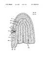
- FIGS. 1A and 1Bare cross-sectional and plan diagrams, respectively, of a heat exchange panel of the prior art referred to by a reference number 100 and disclosed by William Elkins in U.S. Pat. Nos. 4,884,304 and 5,033,136 for a “Bedding System With Selective Heating and Cooling”. Similar heat exchange panels are disclosed by Elkins in U.S. Pat. Nos. 3,830,676 for a “Process of Making a Controlled Thermal Device” and U.S. Pat. No. 4,691,762 for a “Personal Temperature Control System”.
- the heat exchange panel 100includes a first layer 102 and a second layer 104 .
- the first layer 102 and the second layer 104are sealed together at a common border 106 and at fences 108 .
- a liquid 120is pumped so that it flows into an inlet port 122 , through channels 124 between the fences 108 , and out of an outlet port 126 .
- the pressure of the liquid 120causes the channels 124 to bulge to a certain thickness that depends upon the spacing of the fences 108 .
- the panel 100makes external thermal contact at the bulges over the channels 124 .
- the fences 108should be spaced as close together as possible in order for the panel 100 to be as thin as possible. However, spacing the fences 108 closer together requires an increase in the number of fences 108 and thereby reduces the area of the channels 124 where the panel 100 can make thermal contact.
- the border 106 and the fences 108are straight and essentially without wrinkles or ripples.
- the straight border 106 and fences 108cause the panel 100 to buckle when it is expanded with the liquid 120 .
- the bucklingimpedes the flow of the liquid 120 and prevents the panel 100 from conforming closely to complex shapes.
- Elastic materialcould be used to alleviate these problems, however, the dimensions of elastic materials are more difficult to control.
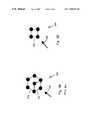
- FIG. 2Ais a plan diagram of a heat exchange panel referred to by a reference number 200 that was developed in part to improve upon the heat exchange panel 100 .
- the heat exchange panel 200includes a first layer that is similar to the first layer 102 ( FIG. 1A ) and a second layer similar to the second layer 104 ( FIG. 1A ).
- the first layer and second layers of the panel 200are sealed together at a common border 206 , at fences 208 , and at dots of a dot matrix 210 .
- the dot matrix 210is organized into first imaginary parallel lines L 12 , second parallel lines 213 , and third parallel lines 214 for connecting each of the dots to the nearest adjacent dots of the dot matrix 210 .
- FIG. 2Bshows each of the dots in the dot pattern. Each is at the center of an arc of six nearest adjacent dots. The six adjacent dots form a hexagonal pattern 216 . Groups of four dots consisting of the center dot and a contiguous three of the nearest adjacent dots form a parallelogram 217 .
- the liquid 120is pumped to flow into an inlet port 222 , between the fences 208 , in a nominal direction 225 through the dot matrix 210 , and out of an outlet port 226 .
- the pressure of the liquid 120causes the channels 224 to bulge between the dots of the dot matrix 210 to a certain thickness that depends upon the spacing of the dots.
- the panel 200makes external thermal contact at these bulges.
- the dots of the dot matrix 210should be spaced as close together as possible in order for the panel 200 to be as thin as possible for conforming to complex shapes of various portions of the human body and avoiding warm spots due to relative stagnation of the liquid flow.
- increasing the number of dots of the dot matrix 210reduces the area of the bulges where the panel 200 can make thermal contact. Consequently, it is important to space the dots of the dot matrix 210 as close together as possible while using a minimum number of dots.
- the heat exchange panel 200 having the dot matrix 210 having the lines 212 – 14 crossing at angles of 600 with the hexagonal pattern 216is not optimum in this respect.
- the panel 200differs from the panel 100 by having trapezoid and triangular shaped wrinkles in the border 206 and the fences 208 .
- the wrinklesreduce the tendency to buckle when the panel 200 is inflated and enable the panel 200 to conform better to complex shapes as compared to the panel 100 .
- the hard or, in other words, adrupt corners of the wrinklesdecrease the laminar flow of the liquid 120 enabling thermal zones of warmer liquid to form, thereby reducing the performance of the heat exchange panel 200 .
- the heat exchange panel of the present inventionincludes first and second layers which are conformable to complex shapes and have seals between the layers at a common border, at fences, and at dots of a dot matrix.
- the dot matrixis organized into first imaginary parallel lines and second imaginary parallel lines that connect each of the dots to the nearest adjacent dots at a 90° angle.
- the first and second parallel linesare generally 45° to the direction of fluid flow.
- the seals at the border and the fencesare rippled with no sharp changes in direction (curvilinear nipples).
- An advantage of a heat exchange panel of the present inventionis that a dot matrix attachment pattern is organized for providing a greater area of thermal contact by minimizing the number of dot attachments for a given panel thickness when inflated and maintaining a more constant panel thickness.
- Another advantage of a heat exchange panel of the present inventionis that border and fence seals are rippled thereby reducing buckling when the panel is inflated.
- An advantage of an active heat exchange panel of the present inventionis that a dot matrix pattern provides a more uniform temperature through better mixing of a fluid flow.
- border and fence sealshave smooth ripples i.e., ripples having no sharp changes in direction as stated above (curvilinear ripples) thereby providing greater compliance and reducing areas of stagnation for a more uniform temperature.
- FIGS. 1A and 1Bare plan and cross-sectional diagrams, respectively, of a first flexible heat exchange panel prior art
- FIG. 2Ais a plan diagram of a second flexible heat exchange panel of the prior art
- FIG. 2Bis an expanded sect in of the plan diagram of the heat exchange panel of FIG. 2B ;
- FIGS. 3A and 3Bare plan and cross-sectional diagrams, respectively, of a flexible heat exchange panel of the present invention.
- FIG. 3Cis an expanded section of the plan diagram of the heat exchange panel of FIGS. 3A–B ;
- FIG. 4is a block diagram of a system of the present invention using the heat exchange panel of FIGS. 3A–C .
- FIGS. 3A and 3Bare a plan and a cross-sectional diagram, respectively, of a heat exchange panel of the present invention and referred to by a reference number 300 .
- the heat exchange panel 300includes a first layer 302 and a second layer 304 .
- the first layer 302 and the second layer 304which layers are conformable to complex shapes are sealed together at a common border 306 , at fences 308 , and at dots of a dot matrix 310 .
- the common border 306is near to the perimeters of the first layer 302 and the second layer 304 but it does not need to be at the exact outside of the first layer 302 or the second layer 304 .
- the dot matrix 310is organized into first imaginary parallel lines 312 and second imaginary parallel lines 314 for connecting each of the dots to the nearest adjacent dots of the dot matrix 310 .
- the lines 312 and 314are approximately perpendicular within a range ⁇ 20°.
- the lines 212 – 14cross at angles of about 60°, thereby requiring a greater number of dots in the dot matrix 210 ( FIGS. 2A–B ) and reducing the area of thermal contact unless the panel 200 is allowed to be thicker.
- the panel 300is filled with a gel, a liquid, or other flexible medium having a desired temperature for transferring heat to or from an external body.
- the panel 300is then wrapped about an external body in a manner to make the greatest area of thermal contact in order to transfer heat between the body and the medium.
- the panel 300is used for cooling a limb, torso, neck, or head of a human being.
- the mediumis replaced when its temperature increases or decreases outside of a desirable range.
- the panel 300is used in an active application where a fluid 320 is pumped to flow into an inlet port 322 , between the fences 308 , through channels 324 in a nominal direction 325 around and past the dots of the dot matrix 310 , and out of an outlet port 326 .
- inlet port 322 and outlet port 326are contiguous.
- the movement of the fluid 320 around the dots of the dot matrix 310causes a continuous mixing of the fluid 320 .
- the mixingis important for avoiding warm spots and maintaining a uniform temperature.
- FIG. 3Cshows an expanded view of a typical section 330 of the panel 300 .
- Each of the dots in the dot patternis a corner of a square pattern 332 .
- the dots of the dot matrix 310may be customized at the bends of the channels 324 to maintain an angle of approximately 45° of the lines 312 and 314 to the direction of the flow of the fluid 320 in the locality of the bends.
- the second parallel lines 213are generally arranged parallel to the nominal direction 225 ( FIGS. 2A–B ) of the flow of the liquid 210 resulting in clear channels where the liquid 210 can avoid mixing.
- the border 306 and the fences 308are smoothly rippled with ripple cycle lengths that are substantially less than the lengths of the border 306 or the fences 308 .
- the resulting smooth ripplesare generally sinusoidal and have a repeating (cyclic) pattern. Such ripples further promote mixing of the fluid 320 .
- the inlet port 322 and the outlet port 326are preferred to have openings in the seal in the border 306 as shown in FIG. 3A .
- the ports 322 and 326may be reversed, thereby reversing the nominal direction 325 of fluid flow.
- the inlet port 322 and/or the outlet port 326may have openings in the first layer 302 or the second layer 304 .
- the fluid 320is a liquid, however, a gas may be used.
- the dots of the dot matrix 310have a diameter of about 0.100 inches and a center to center spacing of about 0.250 inches when the panel 300 is flat.
- the channels 324bulge to a height of about 0.060 to 0.080 inches high by about 0.100 to 0.120 inches wide.
- the first layer 302 and the second layer 304are an impermeable laminate having a fabric, such as Nylon, and three layers of Ether-based Polyurethane.
- the first layer of Polyurethane applied to the fabrichas a relatively low density
- the second layerhas a relatively high density
- the third layerhas a relatively low density in the laminating process that is available from Highland Industries of Framingham, Mass.
- a Radio Frequency (RF) heat sealing processavailable from Ocean Vendors of Byron, Calif., is used for sealing the first layer 302 to the second layer 304 at the border 306 , the fences 308 , and the dots of the dot matrix 310 so that the fabric of the laminate is on the outside of the panel 300 .
- Plates for the sealing processare made of Magnesium with a photo engraving process available from Custom Photo Engraving of Redwood City, Calif. Further information for the materials and processes for constructing the heat exchange panel 300 is disclosed by William Elkins in the U.S. Pat. Nos. 3,830,676, 4,691,762, 4,884,304, and 5,033,136 incorporated herein by reference.
- FIG. 4is a block diagram of a preferred embodiment of a system of the present invention and referred to by a reference number 400 .
- the system 400includes at least one heat exchange panel 300 , the fluid 320 , a heat transfer device such as a heater or a cooler 402 having a temperature control, a reservoir/pump 404 , and conduits 406 , 408 , and 410 .
- the cooler 402cools the fluid 320 to a selected temperature and passes the cooled fluid 320 through the conduit 406 to the heat exchange panel 300 .
- the cooled fluid 320passes through the heat exchange panel 300 where it absorbs or passes heat energy through the first layer 302 and/or the second layer 304 from or to a human body or other external source of heat that is to be cooled or heated. From the heat exchange panel 300 the fluid 320 passes through the conduit 408 to the reservoir/pump 404 .
- the reservoir/pump 404stores a supply of the fluid and pumps the fluid 320 through the conduit 410 to the cooler 402 completing a fluid circuit.
Landscapes
- Health & Medical Sciences (AREA)
- Vascular Medicine (AREA)
- Thermal Sciences (AREA)
- Engineering & Computer Science (AREA)
- Biomedical Technology (AREA)
- Heart & Thoracic Surgery (AREA)
- Physics & Mathematics (AREA)
- Life Sciences & Earth Sciences (AREA)
- Animal Behavior & Ethology (AREA)
- General Health & Medical Sciences (AREA)
- Public Health (AREA)
- Veterinary Medicine (AREA)
- Thermotherapy And Cooling Therapy Devices (AREA)
- Heat-Exchange Devices With Radiators And Conduit Assemblies (AREA)
Abstract
Description
Claims (7)
Priority Applications (3)
| Application Number | Priority Date | Filing Date | Title |
|---|---|---|---|
| US09/127,256US7198093B1 (en) | 1998-07-31 | 1998-07-31 | Compliant heat exchange panel |
| TW088113062ATW425280B (en) | 1998-07-31 | 1999-07-30 | Compliant heat exchange panel |
| PCT/US1999/017298WO2000006062A1 (en) | 1998-07-31 | 1999-07-30 | Compliant heat exchange panel |
Applications Claiming Priority (1)
| Application Number | Priority Date | Filing Date | Title |
|---|---|---|---|
| US09/127,256US7198093B1 (en) | 1998-07-31 | 1998-07-31 | Compliant heat exchange panel |
Publications (1)
| Publication Number | Publication Date |
|---|---|
| US7198093B1true US7198093B1 (en) | 2007-04-03 |
Family
ID=22429158
Family Applications (1)
| Application Number | Title | Priority Date | Filing Date |
|---|---|---|---|
| US09/127,256Expired - Fee RelatedUS7198093B1 (en) | 1998-07-31 | 1998-07-31 | Compliant heat exchange panel |
Country Status (3)
| Country | Link |
|---|---|
| US (1) | US7198093B1 (en) |
| TW (1) | TW425280B (en) |
| WO (1) | WO2000006062A1 (en) |
Cited By (32)
| Publication number | Priority date | Publication date | Assignee | Title |
|---|---|---|---|---|
| US20050256556A1 (en)* | 2004-05-17 | 2005-11-17 | Coolsystems, Inc. | Modular apparatus for therapy of an animate body |
| US20060191063A1 (en)* | 2004-05-11 | 2006-08-31 | William Elkins | Garment for a cooling and hydration system |
| US20080234788A1 (en)* | 2005-11-07 | 2008-09-25 | Wasowski Peter Z | Grounded Pressure Cooling |
| US20090066079A1 (en)* | 2007-09-12 | 2009-03-12 | Coolsystems, Inc. | Make-brake connector assembly with opposing latches |
| US20100139294A1 (en)* | 2008-12-05 | 2010-06-10 | Coolsystems, Inc. | Cooling System Having A Bypass Valve To Regulate Fluid Flow |
| US20100145421A1 (en)* | 2008-12-05 | 2010-06-10 | Coolsystems, Inc. | Therapeutic Cooling and/or Heating System Including A Thermo-Conductive Material |
| US7837638B2 (en) | 2007-02-13 | 2010-11-23 | Coolsystems, Inc. | Flexible joint wrap |
| US20110098792A1 (en)* | 2009-10-22 | 2011-04-28 | Lowe Mark H | Therapeutic wrap |
| US20110106023A1 (en)* | 2009-11-04 | 2011-05-05 | Lowe Mark H | System for providing treatment to a mammal |
| WO2012091759A1 (en) | 2010-12-30 | 2012-07-05 | Coolsystems, Inc. | Reinforced therapeutic wrap and method |
| US8460224B2 (en) | 2010-04-09 | 2013-06-11 | Michael L. Wilford | Therapeutic compression apparatus |
| US9132057B2 (en) | 2012-07-09 | 2015-09-15 | Michael L. Wilford | Therapeutic wrap |
| US9250029B1 (en)* | 2011-03-18 | 2016-02-02 | Christopher Snowden Moore | Detachable article warmer |
| US9510994B2 (en) | 2014-02-07 | 2016-12-06 | Michael L Wilford | Therapeutic wrap with pattern zone |
| US9615967B2 (en) | 2010-12-30 | 2017-04-11 | Coolsystems, Inc. | Reinforced therapeutic wrap and method |
| WO2018136814A1 (en) | 2017-01-19 | 2018-07-26 | Coolsystems, Inc. | Systems and methods for rapid contrast therapy |
| US10456320B2 (en) | 2013-10-01 | 2019-10-29 | Coolsystems, Inc. | Hand and foot wraps |
| US10463565B2 (en) | 2011-06-17 | 2019-11-05 | Coolsystems, Inc. | Adjustable patient therapy device |
| WO2020006316A1 (en) | 2018-06-27 | 2020-01-02 | Coolsystems, Inc. | Thermal performance optimization in a thermal therapy device |
| EP3636229A1 (en) | 2018-10-12 | 2020-04-15 | Cédric Carabalona | Machine and system for cryotherapy treatment of a zone of a human or animal body |
| US10845133B2 (en)* | 2017-10-10 | 2020-11-24 | Other Lab, Llc | Conformable heat exchanger system and method |
| US10859295B2 (en) | 2016-04-13 | 2020-12-08 | ZeoThermal Technologies, LLC | Cooling and heating platform |
| US11143467B2 (en) | 2015-05-20 | 2021-10-12 | Other Lab, Llc | Membrane heat exchanger system and method |
| US11173575B2 (en) | 2019-01-29 | 2021-11-16 | Treau, Inc. | Film heat exchanger coupling system and method |
| US11638675B2 (en) | 2018-11-07 | 2023-05-02 | Zenith Technical Innovations, Llc | System and method for heat or cold therapy and compression therapy |
| US11672693B2 (en) | 2014-08-05 | 2023-06-13 | Avent, Inc. | Integrated multisectional heat exchanger |
| US11779508B2 (en) | 2021-06-25 | 2023-10-10 | Aquilo Sports Llc | Therapeutic pressure, thermal, and/or other treatment modality systems and methods |
| US11850183B2 (en) | 2019-08-20 | 2023-12-26 | Michael L. Wilford | Head wrap |
| US11857491B2 (en) | 2019-03-13 | 2024-01-02 | Breg, Inc. | Integrated cold therapy-compression therapy assembly and associated treatment protocols |
| USD1089665S1 (en) | 2023-11-30 | 2025-08-19 | Michael L. Wilford | Shoulder wrap |
| USD1089667S1 (en) | 2023-11-30 | 2025-08-19 | Michael L. Wilford | Lumbar wrap |
| USD1089666S1 (en) | 2023-11-30 | 2025-08-19 | Michael L. Wilford | Cervical wrap |
Families Citing this family (1)
| Publication number | Priority date | Publication date | Assignee | Title |
|---|---|---|---|---|
| WO2010019577A1 (en) | 2008-08-11 | 2010-02-18 | Infinite Power Solutions, Inc. | Energy device with integral collector surface for electromagnetic energy harvesting and method thereof |
Citations (34)
| Publication number | Priority date | Publication date | Assignee | Title |
|---|---|---|---|---|
| US1958899A (en)* | 1931-06-30 | 1934-05-15 | Macadams Jesse Edward | Heat transfer apparatus |
| FR819022A (en)* | 1937-03-10 | 1937-10-08 | Anciens Etablissements Lamblin | Cooling radiator for airplanes and other applications. |
| US3261042A (en) | 1964-04-14 | 1966-07-19 | Gentex Corp | Buoyant jacket |
| US3320682A (en) | 1965-03-02 | 1967-05-23 | Michael T Sliman | Curler bonnet |
| US3738367A (en) | 1971-02-11 | 1973-06-12 | Angelica Corp | Patient garment with temperature control |
| US3830676A (en) | 1973-02-28 | 1974-08-20 | Acurex Corp | Process of making a contoured thermal device |
| US4147921A (en) | 1977-09-09 | 1979-04-03 | Clairol Inc. | Heat treating articles |
| US4149541A (en) | 1977-10-06 | 1979-04-17 | Moore-Perk Corporation | Fluid circulating pad |
| US4471759A (en)* | 1981-04-28 | 1984-09-18 | B. Shawn Buckley | Method of forming a solar collector or hot water storage tank and solar water heating apparatus using same |
| US4597384A (en)* | 1984-06-29 | 1986-07-01 | Gaymar Industries, Inc. | Sequential compression sleeve |
| US4678027A (en)* | 1984-12-14 | 1987-07-07 | Paul Mueller Company | Dual-walled coiled plate heat exchanger with vented interface |
| US4691762A (en) | 1983-04-01 | 1987-09-08 | Life Support Systems, Inc. | Personal temperature control system |
| US4738119A (en) | 1987-02-09 | 1988-04-19 | Westinghouse Electric Corp. | Integral cooling garment for protection against heat stress |
| US4884304A (en) | 1988-09-28 | 1989-12-05 | Life Support Systems, Inc. | Bedding system with selective heating and cooling |
| US4955435A (en) | 1987-04-08 | 1990-09-11 | Du Pont Canada, Inc. | Heat exchanger fabricated from polymer compositions |
| US5002270A (en) | 1990-01-22 | 1991-03-26 | Shine Anthony G | Exercise vest |
| US5014695A (en)* | 1988-10-04 | 1991-05-14 | Benak Arnold M | Kidney cooling jacket |
| US5033136A (en) | 1988-09-28 | 1991-07-23 | Life Support Systems, Inc. | Bedding system with selective heating and cooling |
| US5080166A (en)* | 1987-04-15 | 1992-01-14 | Itrag Ag | Plate-shaped heating element, in particular for floor heating |
| US5086771A (en) | 1991-09-05 | 1992-02-11 | Cincinnati Sub-Zero Products, Inc. | Configured pad for therapeutic cooling effect |
| US5163425A (en) | 1985-05-27 | 1992-11-17 | Masao Nambu | Deformable cap for scalp cooling |
| US5241951A (en) | 1990-09-05 | 1993-09-07 | Breg, Inc. | Therapeutic nonambient temperature fluid circulation system |
| US5353605A (en) | 1992-10-28 | 1994-10-11 | Coolight Research & Development Ltd. | Personal air cooling device |
| US5417720A (en) | 1990-09-05 | 1995-05-23 | Breg, Inc. | Nonambient temperature pad conformable to a body for therapeutic treatment thereof |
| US5564124A (en) | 1995-04-20 | 1996-10-15 | Bio-Medical Devices, Inc | Personal body ventilation system |
| US5792216A (en) | 1994-06-21 | 1998-08-11 | Mallincrodt Medical, Inc. | Methods of preventing hypothermia using an upper body warming blanket |
| US5913885A (en) | 1991-05-22 | 1999-06-22 | Life Science Holdings, Inc. | Brain cooling device and method for cooling |
| US5967225A (en) | 1998-01-16 | 1999-10-19 | Jenkins; Donny Ray | Body heating/cooling apparatus |
| US5970519A (en) | 1998-02-20 | 1999-10-26 | Weber; Stanley | Air cooling garment for medical personnel |
| US6030412A (en) | 1991-05-22 | 2000-02-29 | Life Science Holdings, Inc. | Apparatus and method for cooling the brain, brain stem and associated neurologic tissues |
| US6117164A (en) | 1997-06-06 | 2000-09-12 | Dj Orthopedics, Llc | Flexible multijoint therapeutic pads |
| US6178562B1 (en)* | 2000-01-28 | 2001-01-30 | Coolsystems, Inc | Cap and vest garment components of an animate body heat exchanger |
| US6551347B1 (en) | 1988-09-28 | 2003-04-22 | Life Enhancement Technologies, Inc. | Cooling/heating system |
| US6695872B2 (en) | 2000-01-28 | 2004-02-24 | Coolsystems, Inc. | Therapy component of an animate body heat exchanger and method of manufacturing such component |
- 1998
- 1998-07-31USUS09/127,256patent/US7198093B1/ennot_activeExpired - Fee Related
- 1999
- 1999-07-30TWTW088113062Apatent/TW425280B/ennot_activeIP Right Cessation
- 1999-07-30WOPCT/US1999/017298patent/WO2000006062A1/enactiveApplication Filing
Patent Citations (35)
| Publication number | Priority date | Publication date | Assignee | Title |
|---|---|---|---|---|
| US1958899A (en)* | 1931-06-30 | 1934-05-15 | Macadams Jesse Edward | Heat transfer apparatus |
| FR819022A (en)* | 1937-03-10 | 1937-10-08 | Anciens Etablissements Lamblin | Cooling radiator for airplanes and other applications. |
| US3261042A (en) | 1964-04-14 | 1966-07-19 | Gentex Corp | Buoyant jacket |
| US3320682A (en) | 1965-03-02 | 1967-05-23 | Michael T Sliman | Curler bonnet |
| US3738367A (en) | 1971-02-11 | 1973-06-12 | Angelica Corp | Patient garment with temperature control |
| US3830676A (en) | 1973-02-28 | 1974-08-20 | Acurex Corp | Process of making a contoured thermal device |
| US4147921A (en) | 1977-09-09 | 1979-04-03 | Clairol Inc. | Heat treating articles |
| US4149541A (en) | 1977-10-06 | 1979-04-17 | Moore-Perk Corporation | Fluid circulating pad |
| US4471759A (en)* | 1981-04-28 | 1984-09-18 | B. Shawn Buckley | Method of forming a solar collector or hot water storage tank and solar water heating apparatus using same |
| US4691762A (en) | 1983-04-01 | 1987-09-08 | Life Support Systems, Inc. | Personal temperature control system |
| US4597384A (en)* | 1984-06-29 | 1986-07-01 | Gaymar Industries, Inc. | Sequential compression sleeve |
| US4678027A (en)* | 1984-12-14 | 1987-07-07 | Paul Mueller Company | Dual-walled coiled plate heat exchanger with vented interface |
| US5163425A (en) | 1985-05-27 | 1992-11-17 | Masao Nambu | Deformable cap for scalp cooling |
| US4738119A (en) | 1987-02-09 | 1988-04-19 | Westinghouse Electric Corp. | Integral cooling garment for protection against heat stress |
| US4955435A (en) | 1987-04-08 | 1990-09-11 | Du Pont Canada, Inc. | Heat exchanger fabricated from polymer compositions |
| US5080166A (en)* | 1987-04-15 | 1992-01-14 | Itrag Ag | Plate-shaped heating element, in particular for floor heating |
| US4884304A (en) | 1988-09-28 | 1989-12-05 | Life Support Systems, Inc. | Bedding system with selective heating and cooling |
| US6551347B1 (en) | 1988-09-28 | 2003-04-22 | Life Enhancement Technologies, Inc. | Cooling/heating system |
| US5033136A (en) | 1988-09-28 | 1991-07-23 | Life Support Systems, Inc. | Bedding system with selective heating and cooling |
| US5014695A (en)* | 1988-10-04 | 1991-05-14 | Benak Arnold M | Kidney cooling jacket |
| US5002270A (en) | 1990-01-22 | 1991-03-26 | Shine Anthony G | Exercise vest |
| US5241951B1 (en) | 1990-09-05 | 1999-07-06 | Breg Inc | Therapeutic nonambient temperature fluid circulation system |
| US5241951A (en) | 1990-09-05 | 1993-09-07 | Breg, Inc. | Therapeutic nonambient temperature fluid circulation system |
| US5417720A (en) | 1990-09-05 | 1995-05-23 | Breg, Inc. | Nonambient temperature pad conformable to a body for therapeutic treatment thereof |
| US5913885A (en) | 1991-05-22 | 1999-06-22 | Life Science Holdings, Inc. | Brain cooling device and method for cooling |
| US6030412A (en) | 1991-05-22 | 2000-02-29 | Life Science Holdings, Inc. | Apparatus and method for cooling the brain, brain stem and associated neurologic tissues |
| US5086771A (en) | 1991-09-05 | 1992-02-11 | Cincinnati Sub-Zero Products, Inc. | Configured pad for therapeutic cooling effect |
| US5353605A (en) | 1992-10-28 | 1994-10-11 | Coolight Research & Development Ltd. | Personal air cooling device |
| US5792216A (en) | 1994-06-21 | 1998-08-11 | Mallincrodt Medical, Inc. | Methods of preventing hypothermia using an upper body warming blanket |
| US5564124A (en) | 1995-04-20 | 1996-10-15 | Bio-Medical Devices, Inc | Personal body ventilation system |
| US6117164A (en) | 1997-06-06 | 2000-09-12 | Dj Orthopedics, Llc | Flexible multijoint therapeutic pads |
| US5967225A (en) | 1998-01-16 | 1999-10-19 | Jenkins; Donny Ray | Body heating/cooling apparatus |
| US5970519A (en) | 1998-02-20 | 1999-10-26 | Weber; Stanley | Air cooling garment for medical personnel |
| US6178562B1 (en)* | 2000-01-28 | 2001-01-30 | Coolsystems, Inc | Cap and vest garment components of an animate body heat exchanger |
| US6695872B2 (en) | 2000-01-28 | 2004-02-24 | Coolsystems, Inc. | Therapy component of an animate body heat exchanger and method of manufacturing such component |
Cited By (62)
| Publication number | Priority date | Publication date | Assignee | Title |
|---|---|---|---|---|
| US7565705B2 (en)* | 2004-05-11 | 2009-07-28 | Biocool Technologies, Llc | Garment for a cooling and hydration system |
| US20060191063A1 (en)* | 2004-05-11 | 2006-08-31 | William Elkins | Garment for a cooling and hydration system |
| US11013635B2 (en) | 2004-05-17 | 2021-05-25 | Coolsystems, Inc. | Modular apparatus for therapy of an animate body |
| US7896910B2 (en) | 2004-05-17 | 2011-03-01 | Coolsystems, Inc. | Modular apparatus for therapy of an animate body |
| US20090005841A1 (en)* | 2004-05-17 | 2009-01-01 | Tamara Lynn Schirrmacher | Modular apparatus for therapy of an animate body |
| US20050256556A1 (en)* | 2004-05-17 | 2005-11-17 | Coolsystems, Inc. | Modular apparatus for therapy of an animate body |
| US9883967B2 (en) | 2005-11-07 | 2018-02-06 | Vasper Systems Llc | Grounded pressure cooling |
| US20080234788A1 (en)* | 2005-11-07 | 2008-09-25 | Wasowski Peter Z | Grounded Pressure Cooling |
| US8273114B2 (en) | 2005-11-07 | 2012-09-25 | Vasper Systems Llc | Grounded pressure cooling |
| US20110028873A1 (en)* | 2007-02-13 | 2011-02-03 | Miros Robert H J | Flexible joint wrap |
| US7837638B2 (en) | 2007-02-13 | 2010-11-23 | Coolsystems, Inc. | Flexible joint wrap |
| US9980844B2 (en) | 2007-02-13 | 2018-05-29 | Coolsystems, Inc. | Flexible joint wrap |
| US7731244B2 (en) | 2007-09-12 | 2010-06-08 | Coolsystems, Inc. | Make-brake connector assembly with opposing latches |
| US20090066079A1 (en)* | 2007-09-12 | 2009-03-12 | Coolsystems, Inc. | Make-brake connector assembly with opposing latches |
| US20100139294A1 (en)* | 2008-12-05 | 2010-06-10 | Coolsystems, Inc. | Cooling System Having A Bypass Valve To Regulate Fluid Flow |
| US20100145421A1 (en)* | 2008-12-05 | 2010-06-10 | Coolsystems, Inc. | Therapeutic Cooling and/or Heating System Including A Thermo-Conductive Material |
| US20110098792A1 (en)* | 2009-10-22 | 2011-04-28 | Lowe Mark H | Therapeutic wrap |
| WO2011050330A2 (en) | 2009-10-22 | 2011-04-28 | Coolsystems, Inc. | Therapeutic wrap |
| EP3714848A1 (en) | 2009-10-22 | 2020-09-30 | Coolsystems, Inc. | Temperature and flow control methods in a thermal therapy device |
| EP3308753A1 (en) | 2009-10-22 | 2018-04-18 | Coolsystems, Inc. | Temperature and flow control methods in a thermal therapy device |
| US9943437B2 (en) | 2009-10-22 | 2018-04-17 | Coolsystems, Inc. | Temperature and flow control methods in a thermal therapy device |
| EP2937065A2 (en) | 2009-10-22 | 2015-10-28 | Coolsystems, Inc. | Temperature and flow control methods in a thermal therapy device |
| US20110106023A1 (en)* | 2009-11-04 | 2011-05-05 | Lowe Mark H | System for providing treatment to a mammal |
| US8460224B2 (en) | 2010-04-09 | 2013-06-11 | Michael L. Wilford | Therapeutic compression apparatus |
| US11547625B2 (en) | 2010-12-30 | 2023-01-10 | Avent, Inc. | Reinforced therapeutic wrap and method |
| CN103402466B (en)* | 2010-12-30 | 2016-03-02 | 酷尔系统公司 | The treatment wrappage strengthened and method |
| US9615967B2 (en) | 2010-12-30 | 2017-04-11 | Coolsystems, Inc. | Reinforced therapeutic wrap and method |
| US8597217B2 (en) | 2010-12-30 | 2013-12-03 | Coolsystems, Inc. | Reinforced therapeutic wrap and method |
| CN103402466A (en)* | 2010-12-30 | 2013-11-20 | 酷尔系统公司 | Reinforced therapeutic wrap and method |
| AU2011353118B2 (en)* | 2010-12-30 | 2016-02-25 | Coolsystems, Inc. | Reinforced therapeutic wrap and method |
| WO2012091759A1 (en) | 2010-12-30 | 2012-07-05 | Coolsystems, Inc. | Reinforced therapeutic wrap and method |
| US9250029B1 (en)* | 2011-03-18 | 2016-02-02 | Christopher Snowden Moore | Detachable article warmer |
| US10463565B2 (en) | 2011-06-17 | 2019-11-05 | Coolsystems, Inc. | Adjustable patient therapy device |
| US9931240B2 (en) | 2012-07-09 | 2018-04-03 | Michael L Wilford | Therapeutic Wrap |
| US9132057B2 (en) | 2012-07-09 | 2015-09-15 | Michael L. Wilford | Therapeutic wrap |
| US9962285B2 (en) | 2012-07-09 | 2018-05-08 | Michael L Wilford | Therapeutic wrap |
| US10806627B2 (en) | 2012-07-09 | 2020-10-20 | Michael L Wilford | Therapeutic wrap |
| US10456320B2 (en) | 2013-10-01 | 2019-10-29 | Coolsystems, Inc. | Hand and foot wraps |
| US9510994B2 (en) | 2014-02-07 | 2016-12-06 | Michael L Wilford | Therapeutic wrap with pattern zone |
| US11672693B2 (en) | 2014-08-05 | 2023-06-13 | Avent, Inc. | Integrated multisectional heat exchanger |
| US11885577B2 (en) | 2015-05-20 | 2024-01-30 | Other Lab, Llc | Heat exchanger array system and method for an air thermal conditioner |
| US11143467B2 (en) | 2015-05-20 | 2021-10-12 | Other Lab, Llc | Membrane heat exchanger system and method |
| US10859295B2 (en) | 2016-04-13 | 2020-12-08 | ZeoThermal Technologies, LLC | Cooling and heating platform |
| WO2018136814A1 (en) | 2017-01-19 | 2018-07-26 | Coolsystems, Inc. | Systems and methods for rapid contrast therapy |
| US12193969B2 (en) | 2017-01-19 | 2025-01-14 | Avent, Inc. | Systems and methods for rapid contrast therapy |
| US11484438B2 (en) | 2017-01-19 | 2022-11-01 | Avent, Inc | Systems and methods for rapid contrast therapy |
| US10845133B2 (en)* | 2017-10-10 | 2020-11-24 | Other Lab, Llc | Conformable heat exchanger system and method |
| US11168950B2 (en)* | 2017-10-10 | 2021-11-09 | Other Lab, Llc | Conformable heat exchanger system and method |
| US11054194B2 (en) | 2017-10-10 | 2021-07-06 | Other Lab, Llc | Conformable heat exchanger system and method |
| WO2020006316A1 (en) | 2018-06-27 | 2020-01-02 | Coolsystems, Inc. | Thermal performance optimization in a thermal therapy device |
| EP4595935A2 (en) | 2018-06-27 | 2025-08-06 | Avent, Inc. | Thermal performance optimization in a thermal therapy device |
| EP3636229A1 (en) | 2018-10-12 | 2020-04-15 | Cédric Carabalona | Machine and system for cryotherapy treatment of a zone of a human or animal body |
| FR3087106A1 (en) | 2018-10-12 | 2020-04-17 | Cedric Carabalona | MACHINE AND SYSTEM FOR TREATMENT BY CRYOTHERAPY OF AN AREA OF A HUMAN OR ANIMAL BODY |
| US11638675B2 (en) | 2018-11-07 | 2023-05-02 | Zenith Technical Innovations, Llc | System and method for heat or cold therapy and compression therapy |
| US11253958B2 (en) | 2019-01-29 | 2022-02-22 | Treau, Inc. | Polymer film heat exchanger sealing system and method |
| US11173575B2 (en) | 2019-01-29 | 2021-11-16 | Treau, Inc. | Film heat exchanger coupling system and method |
| US11857491B2 (en) | 2019-03-13 | 2024-01-02 | Breg, Inc. | Integrated cold therapy-compression therapy assembly and associated treatment protocols |
| US11850183B2 (en) | 2019-08-20 | 2023-12-26 | Michael L. Wilford | Head wrap |
| US11779508B2 (en) | 2021-06-25 | 2023-10-10 | Aquilo Sports Llc | Therapeutic pressure, thermal, and/or other treatment modality systems and methods |
| USD1089665S1 (en) | 2023-11-30 | 2025-08-19 | Michael L. Wilford | Shoulder wrap |
| USD1089667S1 (en) | 2023-11-30 | 2025-08-19 | Michael L. Wilford | Lumbar wrap |
| USD1089666S1 (en) | 2023-11-30 | 2025-08-19 | Michael L. Wilford | Cervical wrap |
Also Published As
| Publication number | Publication date |
|---|---|
| TW425280B (en) | 2001-03-11 |
| WO2000006062A9 (en) | 2000-11-02 |
| WO2000006062A1 (en) | 2000-02-10 |
Similar Documents
| Publication | Publication Date | Title |
|---|---|---|
| US7198093B1 (en) | Compliant heat exchange panel | |
| US7077858B2 (en) | Flexible heat exchangers for medical cooling and warming applications | |
| JP7075701B2 (en) | Devices and equipment | |
| EP1389987B1 (en) | Localized bodily cooling/heating apparatus | |
| JP7005103B2 (en) | Fluid cassette with polymer membrane and integrated inlet and outlet tubes for patient heat exchange system | |
| US11992434B2 (en) | Cold plate design in heat exchanger for intravascular temperature management catheter and/or heat exchange pad | |
| US6551347B1 (en) | Cooling/heating system | |
| US6695872B2 (en) | Therapy component of an animate body heat exchanger and method of manufacturing such component | |
| US6681844B1 (en) | Plate type heat exchanger | |
| EP3091949B1 (en) | Patient heat exchange system with transparent wall for viewing circulating refrigerant | |
| AU2014381670A1 (en) | Heat exchange system for patient temperature control with multiple coolant chambers for multiple heat exchange modalities | |
| CN106102668A (en) | Patient heat exchange system with and only two fluid circuits | |
| US20050061473A1 (en) | Flexible heat exchangers | |
| US20180207027A1 (en) | Heat exchange pad for thermal temperature management | |
| JP2002058694A (en) | Cooling/warming device for living body | |
| CN111256494B (en) | Heat exchangers, thermal management systems for vehicles and vehicles | |
| JPH10300260A (en) | Absorption chiller / heater | |
| CN212132949U (en) | Flexible energy exchange structure and temperature adjusting product with same | |
| CN210441717U (en) | Liquid cooling heat dissipation device | |
| RU1778484C (en) | Stack of counter-current plate-type heat exchanger | |
| JP2002340350A (en) | Cooling/heating mat | |
| JP2731083B2 (en) | Heat storage device | |
| JP2007178100A (en) | Plate heat exchanger | |
| JPH0614767U (en) | Heat dissipation jacket |
Legal Events
| Date | Code | Title | Description |
|---|---|---|---|
| AS | Assignment | Owner name:ORISA TECHNOLOGIES CORPORATION, CALIFORNIA Free format text:ASSIGNMENT OF ASSIGNORS INTEREST;ASSIGNOR:ELKINS, WILLIAM;REEL/FRAME:009370/0087 Effective date:19980730 | |
| AS | Assignment | Owner name:COOLSYSTEMS, INC., CALIFORNIA Free format text:ASSIGNMENT OF ASSIGNORS INTEREST;ASSIGNOR:ORISA TECHNOLOGIES CORPORATION;REEL/FRAME:011600/0050 Effective date:19981014 | |
| STCF | Information on status: patent grant | Free format text:PATENTED CASE | |
| AS | Assignment | Owner name:COMERICA BANK,MICHIGAN Free format text:SECURITY AGREEMENT;ASSIGNOR:COOLSYSTEMS, INC.;REEL/FRAME:024445/0923 Effective date:20100521 Owner name:COMERICA BANK, MICHIGAN Free format text:SECURITY AGREEMENT;ASSIGNOR:COOLSYSTEMS, INC.;REEL/FRAME:024445/0923 Effective date:20100521 | |
| FPAY | Fee payment | Year of fee payment:4 | |
| AS | Assignment | Owner name:COOLSYSTEMS, INC., CALIFORNIA Free format text:RELEASE BY SECURED PARTY;ASSIGNOR:COMERICA BANK;REEL/FRAME:025495/0785 Effective date:20101213 | |
| FPAY | Fee payment | Year of fee payment:8 | |
| FEPP | Fee payment procedure | Free format text:MAINTENANCE FEE REMINDER MAILED (ORIGINAL EVENT CODE: REM.); ENTITY STATUS OF PATENT OWNER: SMALL ENTITY | |
| LAPS | Lapse for failure to pay maintenance fees | Free format text:PATENT EXPIRED FOR FAILURE TO PAY MAINTENANCE FEES (ORIGINAL EVENT CODE: EXP.); ENTITY STATUS OF PATENT OWNER: SMALL ENTITY | |
| STCH | Information on status: patent discontinuation | Free format text:PATENT EXPIRED DUE TO NONPAYMENT OF MAINTENANCE FEES UNDER 37 CFR 1.362 | |
| FP | Lapsed due to failure to pay maintenance fee | Effective date:20190403 | |
| AS | Assignment | Owner name:AVENT, INC, GEORGIA Free format text:ASSIGNMENT OF ASSIGNORS INTEREST;ASSIGNOR:COOLSYSTEMS, INC.;REEL/FRAME:060165/0671 Effective date:20220609 |