US7197282B2 - Mobile station loop-back signal processing - Google Patents
Mobile station loop-back signal processingDownload PDFInfo
- Publication number
- US7197282B2 US7197282B2US10/135,095US13509502AUS7197282B2US 7197282 B2US7197282 B2US 7197282B2US 13509502 AUS13509502 AUS 13509502AUS 7197282 B2US7197282 B2US 7197282B2
- Authority
- US
- United States
- Prior art keywords
- network
- loop
- samples
- transmit
- signals
- Prior art date
- Legal status (The legal status is an assumption and is not a legal conclusion. Google has not performed a legal analysis and makes no representation as to the accuracy of the status listed.)
- Expired - Lifetime, expires
Links
- 238000012545processingMethods0.000titleclaimsabstractdescription80
- 238000004891communicationMethods0.000claimsabstractdescription38
- 239000002131composite materialSubstances0.000claimsabstractdescription34
- 238000000034methodMethods0.000claimsdescription86
- 239000011159matrix materialSubstances0.000claimsdescription71
- 230000000694effectsEffects0.000claimsdescription14
- 238000011045prefiltrationMethods0.000claimsdescription13
- 230000015654memoryEffects0.000claimsdescription10
- 238000001228spectrumMethods0.000claimsdescription8
- 230000004044responseEffects0.000claimsdescription7
- 230000000717retained effectEffects0.000claims16
- 230000005540biological transmissionEffects0.000abstractdescription82
- 238000013459approachMethods0.000description52
- 230000007480spreadingEffects0.000description36
- 230000000875corresponding effectEffects0.000description25
- 238000010586diagramMethods0.000description22
- 238000001914filtrationMethods0.000description18
- 230000008569processEffects0.000description18
- 230000002441reversible effectEffects0.000description14
- 239000013598vectorSubstances0.000description11
- 230000001934delayEffects0.000description9
- 238000005457optimizationMethods0.000description8
- 230000006870functionEffects0.000description7
- 230000007274generation of a signal involved in cell-cell signalingEffects0.000description6
- 239000000203mixtureSubstances0.000description6
- 238000012937correctionMethods0.000description5
- 230000007812deficiencyEffects0.000description5
- 238000009472formulationMethods0.000description5
- 238000004088simulationMethods0.000description5
- 230000008901benefitEffects0.000description4
- 230000015572biosynthetic processEffects0.000description4
- 230000008859changeEffects0.000description4
- 230000002596correlated effectEffects0.000description4
- 238000006880cross-coupling reactionMethods0.000description4
- 230000006872improvementEffects0.000description4
- 238000005259measurementMethods0.000description4
- 238000005562fadingMethods0.000description3
- 230000010363phase shiftEffects0.000description3
- 238000005070samplingMethods0.000description3
- 238000000926separation methodMethods0.000description3
- 230000008054signal transmissionEffects0.000description3
- 238000012935AveragingMethods0.000description2
- 238000004458analytical methodMethods0.000description2
- 238000013461designMethods0.000description2
- 230000003631expected effectEffects0.000description2
- 238000012886linear functionMethods0.000description2
- 230000004048modificationEffects0.000description2
- 238000012986modificationMethods0.000description2
- 230000009467reductionEffects0.000description2
- 230000011664signalingEffects0.000description2
- 230000005477standard modelEffects0.000description2
- QVWYCTGTGHDWFQ-AWEZNQCLSA-N(2s)-2-[[4-[2-chloroethyl(2-methylsulfonyloxyethyl)amino]benzoyl]amino]pentanedioic acidChemical compoundCS(=O)(=O)OCCN(CCCl)C1=CC=C(C(=O)N[C@@H](CCC(O)=O)C(O)=O)C=C1QVWYCTGTGHDWFQ-AWEZNQCLSA-N0.000description1
- 108010003272Hyaluronate lyaseProteins0.000description1
- 238000007476Maximum LikelihoodMethods0.000description1
- 230000009471actionEffects0.000description1
- 239000000654additiveSubstances0.000description1
- 230000000996additive effectEffects0.000description1
- 230000003321amplificationEffects0.000description1
- 230000003750conditioning effectEffects0.000description1
- 230000008878couplingEffects0.000description1
- 238000010168coupling processMethods0.000description1
- 238000005859coupling reactionMethods0.000description1
- 230000009977dual effectEffects0.000description1
- 230000002708enhancing effectEffects0.000description1
- 239000000284extractSubstances0.000description1
- 229910000078germaneInorganic materials0.000description1
- 238000009499grossingMethods0.000description1
- 230000010354integrationEffects0.000description1
- 238000003199nucleic acid amplification methodMethods0.000description1
- 230000002093peripheral effectEffects0.000description1
- 238000012163sequencing techniqueMethods0.000description1
- 230000003595spectral effectEffects0.000description1
- 230000003068static effectEffects0.000description1
- 238000011410subtraction methodMethods0.000description1
- 230000001360synchronised effectEffects0.000description1
- 230000009897systematic effectEffects0.000description1
- 238000012546transferMethods0.000description1
Images


Classifications
- H—ELECTRICITY
- H04—ELECTRIC COMMUNICATION TECHNIQUE
- H04L—TRANSMISSION OF DIGITAL INFORMATION, e.g. TELEGRAPHIC COMMUNICATION
- H04L1/00—Arrangements for detecting or preventing errors in the information received
- H04L1/24—Testing correct operation
- H—ELECTRICITY
- H04—ELECTRIC COMMUNICATION TECHNIQUE
- H04L—TRANSMISSION OF DIGITAL INFORMATION, e.g. TELEGRAPHIC COMMUNICATION
- H04L27/00—Modulated-carrier systems
- H04L27/32—Carrier systems characterised by combinations of two or more of the types covered by groups H04L27/02, H04L27/10, H04L27/18 or H04L27/26
- H04L27/34—Amplitude- and phase-modulated carrier systems, e.g. quadrature-amplitude modulated carrier systems
- H04L27/36—Modulator circuits; Transmitter circuits
- H04L27/366—Arrangements for compensating undesirable properties of the transmission path between the modulator and the demodulator
- H04L27/367—Arrangements for compensating undesirable properties of the transmission path between the modulator and the demodulator using predistortion
- H—ELECTRICITY
- H04—ELECTRIC COMMUNICATION TECHNIQUE
- H04B—TRANSMISSION
- H04B7/00—Radio transmission systems, i.e. using radiation field
- H04B7/005—Control of transmission; Equalising
- H—ELECTRICITY
- H04—ELECTRIC COMMUNICATION TECHNIQUE
- H04B—TRANSMISSION
- H04B7/00—Radio transmission systems, i.e. using radiation field
- H04B7/02—Diversity systems; Multi-antenna system, i.e. transmission or reception using multiple antennas
- H04B7/022—Site diversity; Macro-diversity
- H—ELECTRICITY
- H04—ELECTRIC COMMUNICATION TECHNIQUE
- H04B—TRANSMISSION
- H04B7/00—Radio transmission systems, i.e. using radiation field
- H04B7/02—Diversity systems; Multi-antenna system, i.e. transmission or reception using multiple antennas
- H04B7/04—Diversity systems; Multi-antenna system, i.e. transmission or reception using multiple antennas using two or more spaced independent antennas
- H04B7/06—Diversity systems; Multi-antenna system, i.e. transmission or reception using multiple antennas using two or more spaced independent antennas at the transmitting station
- H04B7/0613—Diversity systems; Multi-antenna system, i.e. transmission or reception using multiple antennas using two or more spaced independent antennas at the transmitting station using simultaneous transmission
- H04B7/0615—Diversity systems; Multi-antenna system, i.e. transmission or reception using multiple antennas using two or more spaced independent antennas at the transmitting station using simultaneous transmission of weighted versions of same signal
- H04B7/0619—Diversity systems; Multi-antenna system, i.e. transmission or reception using multiple antennas using two or more spaced independent antennas at the transmitting station using simultaneous transmission of weighted versions of same signal using feedback from receiving side
- H04B7/0621—Feedback content
- H04B7/0626—Channel coefficients, e.g. channel state information [CSI]
- H—ELECTRICITY
- H04—ELECTRIC COMMUNICATION TECHNIQUE
- H04B—TRANSMISSION
- H04B7/00—Radio transmission systems, i.e. using radiation field
- H04B7/02—Diversity systems; Multi-antenna system, i.e. transmission or reception using multiple antennas
- H04B7/04—Diversity systems; Multi-antenna system, i.e. transmission or reception using multiple antennas using two or more spaced independent antennas
- H04B7/06—Diversity systems; Multi-antenna system, i.e. transmission or reception using multiple antennas using two or more spaced independent antennas at the transmitting station
- H04B7/0613—Diversity systems; Multi-antenna system, i.e. transmission or reception using multiple antennas using two or more spaced independent antennas at the transmitting station using simultaneous transmission
- H04B7/0615—Diversity systems; Multi-antenna system, i.e. transmission or reception using multiple antennas using two or more spaced independent antennas at the transmitting station using simultaneous transmission of weighted versions of same signal
- H04B7/0619—Diversity systems; Multi-antenna system, i.e. transmission or reception using multiple antennas using two or more spaced independent antennas at the transmitting station using simultaneous transmission of weighted versions of same signal using feedback from receiving side
- H04B7/0636—Feedback format
- H—ELECTRICITY
- H04—ELECTRIC COMMUNICATION TECHNIQUE
- H04L—TRANSMISSION OF DIGITAL INFORMATION, e.g. TELEGRAPHIC COMMUNICATION
- H04L1/00—Arrangements for detecting or preventing errors in the information received
- H04L1/0001—Systems modifying transmission characteristics according to link quality, e.g. power backoff
- H04L1/0002—Systems modifying transmission characteristics according to link quality, e.g. power backoff by adapting the transmission rate
- H04L1/0003—Systems modifying transmission characteristics according to link quality, e.g. power backoff by adapting the transmission rate by switching between different modulation schemes
- H—ELECTRICITY
- H04—ELECTRIC COMMUNICATION TECHNIQUE
- H04L—TRANSMISSION OF DIGITAL INFORMATION, e.g. TELEGRAPHIC COMMUNICATION
- H04L25/00—Baseband systems
- H04L25/02—Details ; arrangements for supplying electrical power along data transmission lines
- H04L25/0202—Channel estimation
- H04L25/0204—Channel estimation of multiple channels
- H—ELECTRICITY
- H04—ELECTRIC COMMUNICATION TECHNIQUE
- H04L—TRANSMISSION OF DIGITAL INFORMATION, e.g. TELEGRAPHIC COMMUNICATION
- H04L25/00—Baseband systems
- H04L25/02—Details ; arrangements for supplying electrical power along data transmission lines
- H04L25/0202—Channel estimation
- H04L25/0224—Channel estimation using sounding signals
- H04L25/0226—Channel estimation using sounding signals sounding signals per se
- H—ELECTRICITY
- H04—ELECTRIC COMMUNICATION TECHNIQUE
- H04L—TRANSMISSION OF DIGITAL INFORMATION, e.g. TELEGRAPHIC COMMUNICATION
- H04L25/00—Baseband systems
- H04L25/02—Details ; arrangements for supplying electrical power along data transmission lines
- H04L25/0262—Arrangements for detecting the data rate of an incoming signal
- H—ELECTRICITY
- H04—ELECTRIC COMMUNICATION TECHNIQUE
- H04L—TRANSMISSION OF DIGITAL INFORMATION, e.g. TELEGRAPHIC COMMUNICATION
- H04L25/00—Baseband systems
- H04L25/02—Details ; arrangements for supplying electrical power along data transmission lines
- H04L25/03—Shaping networks in transmitter or receiver, e.g. adaptive shaping networks
- H04L25/03006—Arrangements for removing intersymbol interference
- H04L25/03343—Arrangements at the transmitter end
- H—ELECTRICITY
- H04—ELECTRIC COMMUNICATION TECHNIQUE
- H04B—TRANSMISSION
- H04B1/00—Details of transmission systems, not covered by a single one of groups H04B3/00 - H04B13/00; Details of transmission systems not characterised by the medium used for transmission
- H04B1/69—Spread spectrum techniques
- H04B1/707—Spread spectrum techniques using direct sequence modulation
- H04B1/7097—Interference-related aspects
- H04B1/7103—Interference-related aspects the interference being multiple access interference
- H04B1/7105—Joint detection techniques, e.g. linear detectors
- H—ELECTRICITY
- H04—ELECTRIC COMMUNICATION TECHNIQUE
- H04B—TRANSMISSION
- H04B7/00—Radio transmission systems, i.e. using radiation field
- H04B7/02—Diversity systems; Multi-antenna system, i.e. transmission or reception using multiple antennas
- H04B7/04—Diversity systems; Multi-antenna system, i.e. transmission or reception using multiple antennas using two or more spaced independent antennas
- H04B7/06—Diversity systems; Multi-antenna system, i.e. transmission or reception using multiple antennas using two or more spaced independent antennas at the transmitting station
- H04B7/0613—Diversity systems; Multi-antenna system, i.e. transmission or reception using multiple antennas using two or more spaced independent antennas at the transmitting station using simultaneous transmission
- H04B7/0615—Diversity systems; Multi-antenna system, i.e. transmission or reception using multiple antennas using two or more spaced independent antennas at the transmitting station using simultaneous transmission of weighted versions of same signal
- H04B7/0617—Diversity systems; Multi-antenna system, i.e. transmission or reception using multiple antennas using two or more spaced independent antennas at the transmitting station using simultaneous transmission of weighted versions of same signal for beam forming
- H—ELECTRICITY
- H04—ELECTRIC COMMUNICATION TECHNIQUE
- H04L—TRANSMISSION OF DIGITAL INFORMATION, e.g. TELEGRAPHIC COMMUNICATION
- H04L1/00—Arrangements for detecting or preventing errors in the information received
- H04L1/12—Arrangements for detecting or preventing errors in the information received by using return channel
- H04L1/16—Arrangements for detecting or preventing errors in the information received by using return channel in which the return channel carries supervisory signals, e.g. repetition request signals
- H—ELECTRICITY
- H04—ELECTRIC COMMUNICATION TECHNIQUE
- H04L—TRANSMISSION OF DIGITAL INFORMATION, e.g. TELEGRAPHIC COMMUNICATION
- H04L25/00—Baseband systems
- H04L25/02—Details ; arrangements for supplying electrical power along data transmission lines
- H04L25/0202—Channel estimation
- H—ELECTRICITY
- H04—ELECTRIC COMMUNICATION TECHNIQUE
- H04L—TRANSMISSION OF DIGITAL INFORMATION, e.g. TELEGRAPHIC COMMUNICATION
- H04L25/00—Baseband systems
- H04L25/02—Details ; arrangements for supplying electrical power along data transmission lines
- H04L25/0202—Channel estimation
- H04L25/0212—Channel estimation of impulse response
- H—ELECTRICITY
- H04—ELECTRIC COMMUNICATION TECHNIQUE
- H04L—TRANSMISSION OF DIGITAL INFORMATION, e.g. TELEGRAPHIC COMMUNICATION
- H04L25/00—Baseband systems
- H04L25/02—Details ; arrangements for supplying electrical power along data transmission lines
- H04L25/0202—Channel estimation
- H04L25/0224—Channel estimation using sounding signals
- H04L25/0228—Channel estimation using sounding signals with direct estimation from sounding signals
- H—ELECTRICITY
- H04—ELECTRIC COMMUNICATION TECHNIQUE
- H04L—TRANSMISSION OF DIGITAL INFORMATION, e.g. TELEGRAPHIC COMMUNICATION
- H04L25/00—Baseband systems
- H04L25/02—Details ; arrangements for supplying electrical power along data transmission lines
- H04L25/0202—Channel estimation
- H04L25/024—Channel estimation channel estimation algorithms
- H04L25/0242—Channel estimation channel estimation algorithms using matrix methods
- H04L25/0244—Channel estimation channel estimation algorithms using matrix methods with inversion
Definitions
- the present inventiongenerally applies to wireless communication systems, and particularly applies to using receiver loop-back signals to improve communication system performance.
- Wireless communicationinvolves, in the most general sense, transmitting information from one location to another.
- a transmittergenerates one or more transmit signals that is somehow varied, i.e., modulated, in accordance with desired transmit information.
- a receiverextracts the transmitted information from a received signal by detecting and decoding its signal modulations. In an ideal system, the originally transmitted signal modulations and, hence, the transmitted data, are perfectly preserved in the received signal.
- Received signalsseldom have perfect correspondence to transmitted signals because of downlink channel distortions.
- Propagation path characteristics of the radio mediuminclude time-varying attenuation, phase shift, fading, and multipath reflections. Further variance between the transmit information and recovered received information arises from the non-ideal performance of transmitters and receivers.
- Signal transmission and receptioninvolves signal filtering, amplification, and modulation, all of which may impart signal distortion.
- wireless receivers“learn” downlink channel characteristics and use the “learned” channel characteristics to compensate received signal distortions based on the estimated downlink channel.
- a common approach to downlink channel estimationinvolves the transmitter sending known information as part of the transmit signal. By looking at distortions in the known portion(s) of the received signal, the receiver develops estimates of the downlink channel, which it then uses to compensate the received signal. Because distortion changes rather rapidly in mobile environments, the typical mobile station receiver frequently updates its downlink channel estimates.
- one or more network transmitterstransmit signals to one or more mobile stations, which, in turn, transmit signals back to one or more network receivers.
- the mobile stationscommonly perform downlink channel estimation to compensate their respective received signals and, similarly, the network receiver(s) perform uplink channel estimation to compensate the signals received from the mobile stations.
- a wireless receiverwhether at the mobile station or the network, to improve its reception performance by compensating its received signal using estimates of the channel through which the signal was received.
- a wireless transmitterpre-compensates its transmit signal for expected downlink channel distortions. That is, if the wireless transmitter has access to reasonably good estimates of the channel through which its transmitted signal will travel, it can alter the transmit signal in a manner that lessens the effects of transmit channel distortions on the signal received at the wireless receiver.
- transmit signal pre-compensationis in obtaining downlink channel estimates. Obtaining such estimates can be challenging because the process generally involves obtaining loop-back information from the receiver(s) that actually receive the transmitted signal to which pre-compensation is applied.
- the present inventionprovides methods and apparatus for forming loop-back signals at mobile stations to be transmitted to the network, and for processing such loop-back signals at a wireless communication network to determine downlink channel characteristics.
- the networkforms one or more combined transmit signals that include individual information signals for each of a plurality of mobile stations.
- Each mobile stationreceives a composite signal including information intended for the other mobile stations, and transmits a loop-back signal derived from the composite signal back to the network for processing.
- the networkdetermines transmit channel compensation information, which it uses to pre-compensate the signals transmitted by the network to the mobile stations.
- the mobile stationsestimate downlink channels and convey such estimates as loop-back information to the network, which uses the received estimates for transmit pre-compensation.
- Loop-back processing techniquesin which the network estimates downlink channel characteristics based on analyzing loop-back signal samples from the mobile stations rely on the network storing or otherwise memorizing transmit signal information for the combined transmit signal or signals transmitted to the mobile stations. With such information, the network compares the loop-back information received from the mobile stations to corresponding memorized information to determine transmit channel characteristics, which may include selected transmit and receive processing, as well as the physical downlink channel. More particularly, loop-back signal processing at the network may include block-processing approaches wherein blocks of loop-back samples are correlated with memorized transmit signal information to obtain transmit channel characteristics.
- Kalman FilteringLeast Squares Forever
- Exponential Filtering approachesSuch approaches themselves include various refinements, including the use of Kalman Trackers to track loop-back signal changes, wherein the effect of transmit signal dynamic encoding changes on loop-back signal characteristics are removed by pre-filtering the loop-back signals in advance of the Kalman Trackers using, for example, Kalman Filtering.
- transmit signal compensationmay pre-compensate the combined transmit signals at the transmit modulation rate (transmit rate pre-compensation), or pre-compensate the individual information symbol streams intended for the different mobile stations at the information symbol rate (information rate pre-compensation), or combinations thereof.
- the networkmemorizes the combined transmit signals transmitted by it to the mobile stations, while in the latter case it memorizes the individual information symbol streams intended for the different mobile stations.
- the mobile stationsderive loop-back samples from the composite signal received by each mobile station.
- each mobile stationloops back signal samples obtained from the composite signal received by that mobile station.
- Such loop-back informationenables the network to determine the combining characteristics of its combined transmit signal or signals as received by the mobile stations through the downlink channel(s), and use these characteristics to pre-compensate, such as by pre-filtering, the combined transmit signal(s) at the network for the expected downlink channel characteristics.
- each mobile stationgenerally loops back processed signal samples derived from processing the composite signal received at that mobile station. For example, if the mobile stations use RAKE or GRAKE receivers, each mobile station might loop back “soft” output values obtained from the composite signal by its receiver. Regardless, one notable aspect of this approach is that, in contrast to the composite signal loop-back above, each mobile station loops back samples of its intended information signal separated from the received composite signal. With such loop-back information, the network can determine the relative interference between the individual information signals (i.e., individual symbol streams) intended for the different mobile stations, and can therefore pre-compensate the individual information streams at the network for such observed interference in advance of forming the combined transmit signals.
- the individual information signalsi.e., individual symbol streams
- the mobile stationsmay loop back composite received signal samples, and the network may derive the processed output values that would be output at each mobile station, e.g., the soft output values. That is, the network might model the composite received signal processing employed by the mobile stations to predict the values being extracted from the composite received signal by each mobile station. With this technique, the mobile stations feed back composite received signal samples, which simplifies in some respects loop-back signal generation at the mobile stations, yet the network applies transmit pre-compensation to the individual information symbol streams using symbol rate processing.
- the ability to derive processed samples representative of the processed sample values being generated at each mobile stationfurther enables the network to combine pre-compensation of its combined transmit symbols with pre-compensation of the individual information symbol streams from which the combined transmit symbols are formed. That is, the network can efficiently combine transmit rate and symbol rate pre-compensation.
- Such combined transmit pre-compensationenables the network to simultaneously increase transmission efficiency and reduce interference at the mobile stations. Transmit efficiency may be improved by tailoring combined transmit signal powers through adjustment of the combining weights used to form the combined transmit signals, while interference at the mobile stations may be reduced by compensating the information symbol streams for inter-signal interference as experienced at the mobile stations.
- the present inventionis adaptable for use in essentially any type of wireless communication network.
- the networkuses Time Division Multiple Access (TDMA) techniques
- the networkmight employ a plurality of transmit antennas for transmitting combined transmit signals to one or more mobile stations.
- transmit pre-compensationmight involve the use of a transmit pre-filter having filter coefficients that determine the weighted combinations used to form the combined transmit signals, and wherein loop-back processing operates to adjust such transmit pre-filtering based on the determined transmit channel characteristics.
- the networkmight transmit a single combined signal from a single transmit antenna to a plurality of mobile terminals.
- the networkmight use processed sample loop-back information to determine undesirable cross-correlations between the individual information signals intended for the different mobile stations. With determination of such cross-correlation estimates, the network can, as noted earlier, compensate the individual information symbol streams for the estimated cross-correlation.
- CDMACode Division Multiple Access
- the networkuses estimated transmit channel characteristics to pre-compensate it transmit signal(s) for the expected effects of the transmit channel.
- pre-compensationinvolves, in the various exemplary embodiments, pre-compensation of the individual information signals intended for the different mobile stations based on cross-correlation compensation of those signal streams, and/or pre-compensation of the combined information streams used to form the combined transmit signal(s).
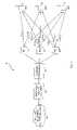
- FIG. 1is a diagram of an exemplary wireless communication network according to one embodiment of the present invention.
- FIG. 2is a diagram of exemplary transmit pre-compensation processing functions.
- FIG. 3is a functional block diagram of network transmissions to a mobile station according to an exemplary embodiment of the present invention.
- FIG. 4is a more detailed functional block diagram of the network transmission arrangement of FIG. 3 .
- FIG. 5is a functional block diagram illustrating exemplary network reception and processing of the loop-back signals generated in the illustrations of FIGS. 3 and 4 .
- FIG. 6is a diagram of an exemplary base station transmitter.
- FIG. 7Ais a diagram of an exemplary mobile station receiving combined transmit signals.
- FIG. 7Bis a diagram of an exemplary mobile station transmitter providing loop-back.
- FIG. 8is a diagram of exemplary transmit pre-compensation functions for CDMA-type transmissions.
- FIG. 9is a diagram of exemplary transmit pre-compensation using network transmitters with differently polarized antennas.
- FIG. 10Ais a diagram of exemplary transmit pre-compensation combining symbol rate and transmit rate pre-compensation.
- FIG. 10Bis a diagram of an exemplary alternate embodiment for combined transmit pre-compensation.
- FIG. 11is a diagram of an exemplary downlink channel span.
- FIG. 12Ais a diagram of the overall downlink/uplink (loop-back channel).
- FIG. 12Bis a diagram of an exemplary ordering of estimated downlink and uplink channels as used in some embodiments of transmit pre-compensation.
- FIG. 13is a diagram of another exemplary embodiment for transmit pre-compensation.
- FIG. 14is a diagram of an exemplary RAKE receiver-based mobile station.
- FIG. 15is a diagram of exemplary loop-back signal formation.
- FIG. 16is a diagram of exemplary transmit pre-compensation based on mobile-estimated transmit channel information.
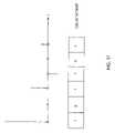
- FIG. 17is a diagram of an exemplary propagation path delay bitmap.
- the present inventionis directly applicable to a wide variety of wireless communication network types, such as those based on TDMA schemes, and those based on CDMA schemes.
- Exemplary standards to which the present invention appliesinclude, but are not limited to, the TIA/EIA/IS-136, TIA/EIA/IS-95, and TIA/EIA/IS-2000 (cdma2000) published by the Telecommunications Industry (TIA) Association and the Electronics Industry Association (EIA), and Wideband CDMA (WCDMA).
- the present inventioninvolves a fixed network of stations transmitting information using one or more antennas to one or more outstations (e.g., remote receivers) such as mobile stations.
- the mobile stationsreceive overlapping transmitted signals from the multiple network antennas.
- the mobile stationstransmit signals back to the network stations from which the network stations can determine characteristics of the downlink propagation channels from each network transmitting antenna to each mobile station.
- the network stationsthen precondition the transmitted signals for each network transmitting antenna to enhance network transmissions.
- Such enhancementsmight include, but are not limited to, improvements in network transmission efficiency, and improvements in signal quality at the mobile stations.
- each mobile stationreceives a network-transmitted signal in an allocated channel bandwidth and samples the received signal.
- the received signal samplesare then combined with signal samples originating at the mobile station and the combined sample stream is then converted to a continuous signal using transmit filters, up-converted and transmitted from the mobile station back to the network.
- This loop-back signal from the mobile station to the networkallows the network to determine downlink channel characteristics, as seen by the mobile station.
- the network stations of the preferred implementationreceive, possibly using multiple antennas, the signals transmitted by the mobile stations and process these received signals to determine characteristics of the uplink propagation paths from the mobile station transmitters to the network receivers.
- the determined uplink propagation channel characteristicsare then employed in correlating loop-back signals with the signals transmitted by the network antennas to determine characteristics of the downlink propagation paths from the network's transmitting antennas to the mobile stations.
- the networkuses the determined downlink propagation path characteristics to condition the signals transmitted from the network antennas to the mobile stations to, for example, maximize transmission efficiency and received signal quality.
- FIG. 1illustrates an exemplary wireless communication network generally referred to by the numeral 10 .
- Network 10is generally like the wireless networks presented in the previously incorporated parent applications, and it should be understood that presentation of network 10 is simplified for clarity. Network 10 might include considerably more sophistication in actual implementation, and a number of network entities that might be included in an actual wireless network are not shown. However, such complexities are not germane to understanding the present invention.
- network 10comprises one or more base stations (BSs) 12 that, in combination with an interface/control entity 14 , provide wireless communication support to a plurality of mobile stations (MSs) 16 .
- the network 10further includes a transmit processing system 18 , which might be a distributed system, to provide pre-compensation processing for the signals transmitted by the network to the MSs 16 .
- BSsbase stations
- MSsmobile stations
- the interface/control entity 14provides traffic routing and overall control, such as call setup, etc., for the BSs 12 , and interfaces the network 10 to one or more external networks 20 , such as the Public Switched Telephone Network (PSTN) and the Internet.
- PSTNPublic Switched Telephone Network
- the interface/control entity 14might be, for example, a Mobile Switching Center (MSC), a packet-based gateway router, such as a Packet Data Serving Node (PDSN), or a mixture of such entities.
- MSCMobile Switching Center
- PDSNPacket Data Serving Node
- the present inventionapplies to both circuit-switched and packet-switched network arrangements, and to combinations thereof.
- FIG. 2illustrates an exemplary embodiment of network 10 .
- transmit processing system 18comprises pre-compensation processor 30 , loop-back processor 32 , and supporting memory 34 .
- Memory 34comprises, in exemplary embodiments, one or more memory devices and/or storage systems, and may include, but is not limited to, solid-state memories, magnetic memory such as disk drives, or combinations thereof.
- BSs 12each comprise, in at least some exemplary embodiments, an interface/control processor 40 , radio transmitters 42 , radio receivers 44 , and one or more antennas 46 .
- a single BS 12might represent a set of receiver/transmitter radio resources supporting one or more sectors of network 10 and operating under control of an MSC, for example.
- each BS 12might represent a Base Station System (BSS), including a Base Station Controller (BSC) with an associated plurality of Radio Base Stations (RBSs) or Base Transceiver Systems (BTSs).
- BSSBase Station Controller
- RBSsRadio Base Stations
- BTSsBase Transceiver Systems
- one or more BSs 12can be used to provide multiple transmission sites for the associated network 10 .
- a given BS 12operates as a single transmission site transmitting a single, combined transmit signal to a plurality of MSs 16 , while in other embodiments, it transmits one or more combined transmit signals from two or more relatively closely spaced transmission antennas or antenna elements.
- each BS 12serves as a network transmitter with one or more transmitting antennas when used in practicing loop-back as disclosed in the parent applications.
- Each receiveri.e., MS 16
- receives signals from the network antennas 46 in an assigned frequency channelconverts the signals to representative samples, combines locally generated samples such as pilot code samples to the received samples, then converts the combined samples to a transmit signal for transmission back to the network 10 as a loop-back signal.
- the loop-back signal transmitted back to the network 10 from each MS 16comprises the looped-back received signal and the locally generated signal samples, the latter being useful to the network 10 to separate out the uplink propagation path characteristics.
- various methods of signal combining at the MSs 16are disclosed that can be advantageous in different circumstances.
- the network 10In operation, the network 10 generates combined pre-transmit signals T 1 ′, T 2 ′, and T 3 ′, based on forming a combination of information symbol streams S 1 , S 2 , and S 3 , each containing desired information for a corresponding one of the MSs 16 (i.e., MS 1 , MS 2 , and MS 3 ).
- Transmit processing system 18transfers the combined pre-transmit symbols to respective ones of the BSs 12 , such that a first base station 12 transmits combined transmit signal T 1 , a second base station 12 transmits combined transmit signal T 2 , and a third BS 12 transmits combined transmit signal T 3 , T 1 , T 2 , and T 3 are formed at the respective BSs 12 based on, for example, modulating a carrier signal at the desired transmit frequency with the combined symbol information contained in the pre-transmit signals T 1 ′, T 2 ′, and T 3 ′.
- FIG. 3depicts the network 10 as it relates to the determination of downlink channels between multiple network transmit antennas 46 - 1 through 46 -n, which may be co-located at a single network transmission site, e.g., positioned at a single BS 12 , and a first receiver, e.g., a given MS 16 .
- a single network transmission sitee.g., positioned at a single BS 12
- a first receivere.g., a given MS 16 .
- x i [m]is a complex baseband signal transmitted by the i-th transmit antenna, e.g., 46 -i, and is output by the i-th summer as the sum of two signals: (1) the information signal s i [m]; and (2) a pilot signal p i [m].
- the signal s i [m]is a data-bearing signal transmitted from the i-th network transmit
- p i [m]is a pre-determined signal that generally carries no data but is useful in aiding network-determination of loop-back information.
- FIG. 4illustrates a more detailed block diagram.
- c i1 [m]is the downlink channel from the i-th network transmit antenna to the first MS 16
- d i1 [m]is the uplink channel from the first MS 16 to the i-th network receive antenna, which may be the same as network transmit antenna 46 -i, or co-located therewith.
- the signal p 1 [m]is a pilot signal being transmitted on the uplink channel by MS 16 , and this pilot signal is known to the network 10 .
- the goalis to determine the downlink channel characteristics ⁇ c 11 [m], . . . ,c n1 [m] ⁇ based on:
- the time ordering of FIG. 4may be, for purposes of analysis, re-imagined in a reverse order where the uplink channels are positioned in advance of the downlink channels.
- a proposed exemplary method for determining the downlink channels at the network 10is as follows:
- Step (3)An exemplary embodiment for Step (3) above is presented here.
- ⁇ right arrow over (v) ⁇ ibe a vector of N consecutive samples of v i [m]
- ⁇ right arrow over (r) ⁇ ito be a vector of N consecutive samples of r i [m]
- r ⁇ iA i1 ⁇ x ⁇ [ c ⁇ 11 c ⁇ 2 ⁇ 1 ⁇ c ⁇ n1 ] ⁇ c ⁇ 1 + ( v ⁇ i + w ⁇ i ) , 1 ⁇ i ⁇ n ( 1 )
- ⁇ right arrow over (c) ⁇ i1is a vector of non-zero taps of c i1 [m]
- ⁇ right arrow over (w) ⁇ iis a vector representing all other sources of interference and noise at the i-th network receive antenna
- a i1is a convolution matrix whose entries only depend on ⁇ s 1i [m], s 2i [m], . . . , s ni [m] ⁇ .
- the signals received from all the network receive antennase.g., all the receive antennas at BS 12 , may be expressed as a function of all of the downlink channels as follows,
- the quality of the above estimatedepends on the properties of (B 1 H B 1 ), which should be as close as possible to a scaled diagonal matrix. To this end, one would like each x i [m] to be as uncorrelated as possible with the other x j [m]'s transmitted by network 10 , and would further like each x i [m] to have deterministic auto-correlation as close as possible to a delta function.
- the worst estimation performancearises when the (B 1 H B 1 ) matrix is singular, i.e. in this case even with no noise at all, the downlink channels cannot be uniquely determined by the network 10 .
- the pilot signals, ⁇ p 1 [m], . . . ,p n [m] ⁇are added by network 10 to its transmissions to ensure that (B 1 H B 1 ) does not become singular, and to make (B 1 H B 1 ) as close as possible to a scalar identity matrix.
- the network 10can determine the downlink channel estimates ⁇ 11 [m], . . . , ⁇ n1 [m] ⁇ by treating the downlink channel(s) as a linear time-invariant channel with n 2 inputs and n outputs. That is, the known inputs are ⁇ s 11 [m], . . . , s n1 [m]; . . . ; s 1n [m], . . . , s nn [m] ⁇ , and the known outputs (the received feedback signals) are ⁇ r 1 [m], . . . ,r n [m] ⁇ .
- a modulator 48modulates an RF carrier signal provided by RF generator 50 responsive to one of the combined transmit signals T 1 ′, T 2 ′, and so on, generically represented as combined transmit signal Tx′.
- the combined transmit signalsmay be, as detailed above, formed by summing one or more individual information signals intended for a specific MS 16 , or selected ones in a group of MSs 16 , along with a known pilot signal.
- carrier generation at each of the network transmit sitescan be synchronized by using, for example, a synchronization signal generated by network 10 .
- transmit processing system 18can generate a synchronization signal (or signals) for maintaining synchronization between the BSs 12 , such that the combined transmit signals are transmitted with the desired synchronization.
- each MS 16receives a composite signal representing a combination of the transmissions from each one of the BSs 12 .
- the particular manner in which the transmit signals combine at each MS 16depends on the downlink propagation characteristics between that MS 16 and the respective ones of the BSs 12 .
- Each MS 16transmits a loop-back signal to the network 10 , which the network 10 , via loop-back processor 32 , processes to determine downlink channel characteristics, such that the network's transmissions to the MSs 16 may be pre-compensated for expected downlink channel distortions.
- MSs 16form the loop-back signals to include samples from the received composite signal, or using processed samples obtained from the MS's receiver.
- looped back composite signal samplesgenerally are used by the network 10 to perform transmit rate pre-compensation, while the processed samples looped back from the MSs 16 generally are used to perform symbol rate pre-compensation. Distinctions between these two pre-compensation approaches are discussed in more detail later.
- the overall operation of network 10 with regard to loop-back signal processingis such that downlink propagation information is obtained by comparing loop-back information obtained from the loop-back signals with corresponding transmit information, after removal of the uplink propagation effects from the loop-back signals. That is, information in the loop-back signals representative of the network's own transmissions is processed to remove the effects of uplink propagation, such that comparing that information with original transmit information reveals the effects of downlink propagation.
- network 10stores, at least temporarily, transmit signal information in memory 34 for use by loop-back processor 32 .
- comparison-type processingincluding correlation of loop-back symbol information with the corresponding information symbol information in previously transmitted portions of the information symbol streams S 1 , S 2 , and S 3 .
- Comparison processingmight, particularly where composite signal information is looped back, be based on the combined transmit signals (e.g., T 1 ′, T 2 ′, and so on), in which case, the combined transmit signals are saved to memory 34 as the transmit information used by loop-back processor 32 .
- FIG. 7Aillustrates exemplary details for MSs 16 .
- the exemplary MS 16comprises a switch/duplexer 60 coupling a receiver 62 and transmitter 64 to an antenna assembly 61 , a baseband processor 66 , a system processor 68 , and a user interface 70 .
- User Interface 70typically comprises a keypad, display screen, and audio input/output systems (not shown), while system processor 68 provides overall control of the MS 16 , and often provides specific control of User Interface 70 .
- Baseband processor 66generally provides signal processing functions for received signal processing and transmit signal generation.
- FIG. 7Billustrates additional transmitter details, and depicts an exemplary transmitter 64 as comprising a summing circuit 72 , a modulator 74 , and a power amplifier (PA) 76 .
- the receiver 62couples samples of the composite received signal back to the transmitter 64 via the summing circuit 72 .
- PApower amplifier
- the summing circuit 72may be used to combine signal samples looped back from the receiver 62 with pilot code information. That is, the MS 16 generates its loop-back signal as a combination of its received signal information and known pilot information. In this manner, the network 10 can more easily identify uplink channel affects by examining distortions in the received pilot information, since that information is known to the network 10 and was transmitted only through the uplink channel.
- FIG. 8illustrates an exemplary embodiment of the present invention in which a single antenna, represented as a single BS 12 , transmits pre-compensated signals to a plurality of MSs 16 .
- the transmit processing system 18comprises a “matrix pre-combiner” as pre-compensation processor 30 , and includes loop-back processor 32 and memory 34 as before, as well as a spread spectrum coder 80 .
- Pre-compensation processor 30pre-compensates individual information symbol streams, S 1 , S 2 , and S 3 , for expected cross-correlation interference using symbol rate processing, based on knowledge of the CDMA spreading codes used in coder 80 and on the determined downlink channel characteristics, to minimize interference between signals destined for different receivers. That is, spread spectrum coder 80 encodes the pre-compensated symbol streams, S 1 ′, S 2 ′, and S 3 ′ for CDMA transmission.
- pre-compensation processor 30In generating the pre-compensated symbol streams, pre-compensation processor 30 compensating the corresponding input symbol streams, S 1 , S 2 , and S 3 , for cross-correlation interference determined from the loop-back signals from MS 1 , MS 2 , and MS 3 by loop-back processor 32 .
- Such pre-compensationinvolves, in some embodiments of the present invention, determining a cross-correlation matrix between wanted and unwanted signals at each MS 16 based on processing loop-back information from the MSs 16 .
- loop-back processor 32determines coefficients for a cross-correlation compensation matrix by which the individual information streams S 1 , S 2 , and S 3 are multiplied such that the signals received by each MS 16 combine in a manner that tends to reduce wanted and unwanted signal cross-correlation.
- FIG. 9illustrates yet another application, in which dual polarized network antennas are co-located at a network transmitter 82 .
- the two antennasmight comprise orthogonally polarized antennas.
- information for the MSs 16is preconditioned for transmission by the two antennas using transmit rate processing (e.g., chiprate processing) to optimize transmission to each MS 16 independently.
- transmit rate processinge.g., chiprate processing
- Network 10generally requires, in both FIGS. 8 and 9 , downlink channel information to optimize transmissions to the MSs 16 .
- FIG. 9illustrates the presence of an informational deficiency when determining two downlink channels from only one loop-back signal, which however was solved in the parent applications by transmitting at least one “dummy” pilot signal as well as the information bearing signals.
- FIG. 10Adepicts network 10 as a combination of the approaches illustrated in FIGS. 8 and 9 , in which transmissions to the MSs 16 are optimized using both transmit rate processing to increase transmission efficiency, and symbol rate processing to pre-cancel interference between information symbols intended for different MSs 16 .
- the illustrationdepicts a scenario where the network 10 transmits “n” combined transmit signals to “m” MSs 16 .
- network 10comprises transmit processing system 18 , CMDA coders 80 , network transmitters 42 and corresponding network antennas 46 .
- transmitters 42might comprise the transmitter portion of BSs 12 , as shown in earlier embodiments.
- Transmit processing system 18comprises, in this embodiment, matrix pre-combiner 86 , pre-filters 88 , and summing circuits 90 .
- pre-combiner 86receives individual information symbol streams S 1 , S 2 , . . . Sm, corresponding to the desired information for each of the MSs 16 , e.g., MS 1 , MS 2 , . . . , MSm.
- Pre-combiner 86compensates these individual symbol streams for expected downlink cross-correlation interference based on cross-correlation estimates generated by loop-back processor 32 , which determines such estimates based on loop-back information obtained from the loop-back signals from the MSs 16 .
- symbol streams S 1 , S 2 , . . . Sm for transmission to respective MSs MS 1 , MS 2 , . . . MSmenter pre-combiner 86 , which forms linear combinations of the symbol streams based on the total downlink channel characteristics and correlations between the spreading codes used in CDMA coders 80 - 1 , 80 - 2 , . . . 80 - m , comprised of codes 1 , 2 , . . . m.
- the symbolsmay be bits or higher order symbols such as complex 8 Phase Shift Keying (PSK) constellation points.
- PSKPhase Shift Keying
- the total downlink channel in this contextmeans the channel describing propagation from the output of coder(i) (which is input to the pre-filters 88 of first index i) to the receiver output of the j-th MS 16 , which may be the output of a RAKE combiner.
- the downlink channelincludes the pre-filters 88 after the CDMA coders 80 , and thus comprises a “net” downlink channel inclusive of the diversity effect of using up to ‘n’ antennas 46 for transmitting to each MS 16 .
- the linear combinations of symbols S 1 to Smare denoted by X 1 to Xm and represent multi-level values that are not necessarily equal to symbol constellation values. These Xi values are generated at the symbol rate and multiplied by corresponding spreading code(i) to form a chip-rate stream.
- transmit rate processingdenotes processing performed at the spreading chip rate on the linear combinations of the individual information symbol streams
- symbol rate processingdenotes the cross-correlation pre-compensation performed at the underlying information symbol rate.
- the symbol streamsare already equal to the final chip-rate and the CDMA coders 80 merely perform a 1:1 symbol-wise scrambling that does not further increase the chip rate.
- the error correction coding prior to the formation of symbols S 1 to Smis a small factor in the total spreading, and the final spreading from symbol rate to chip rate performed by coders 1 to m is by a large factor.
- the chip-rate streams of complex numbers from coders 80 - 1 to 80 -mare transmitted using any or all of antennas 46 - 1 to 46 - n , after pre-filtering by pre-filters 88 - 1 to 88 - m , in such a way as to maximize transmission efficiency.
- more powershould be transmitted from the antenna 46 having the lowest path loss to a target MS 16 , and this characteristic is achieved by practicing the teachings of the parent applications.
- the pre-filter Pij(z) for conditioning the signals from coder 88 -i for antennas 46 - 1 to 46 - ncan be equal to the time-reverse conjugate transpose of the matrix Cji(z) describing the downlink propagation channels from antenna j to receiver i, where each Cji is a z-polynomial for a multipath channel.
- the total power transmitted for each MS 16may be scaled by an overall power control factor to maintain a desired signal level at the MSs 16 to combat noise and interference other than the interference cancelled by pre-combiner 86 .
- the target desired signal levelmay be signaled from each receiver (i.e., MS 16 ) to the network 10 by a signal quality feedback channel, or else may be deduced by the network from the loop-back signals returned from each receiver, wherein the noise and un-cancelled interference levels will be evident.
- FIG. 10Bshows a slightly more general form for the arrangement illustrated in FIG. 10A .
- the inputs to all the chip-rate pre-filters Pij(z) associated with transmission to the same MS 16are identical.
- the symbol-rate pre-combiningproduces different symbol combinations for each antenna 46 , as disclosed in the parent applications for non-CDMA systems.
- pre-combinations to be transmitted by the same antenna 46were added.
- the pre-combinationsare first spread using respective CDMA coders 80 to obtain CDMA coded spread-spectrum signals to be transmitted from each antenna 46 , which are then also subjected to separate chip-rate pre-filtering via pre-filters 88 prior to addition by summing circuits 90.
- symbol rate processingcancels mutual interference between the transmissions included in the network's joint transmission scheme. That is, symbol rate pre-compensation reduces interference between the signals intended for the different MSs 16 that are included in the combined transmit signals from network 10 .
- transmit rate processinghere embodied as chip-rate pre-filtering, optimizes or otherwise improves the signal-to-noise plus interference ratio (SNIR) due to interference from other transmissions not included in the network's transmit scheme.
- SNIRsignal-to-noise plus interference ratio
- the combined optimization of both symbol-rate and chip-rate pre-compensation filteringrequires knowledge of the downlink propagation channels, which may be provided by loop-back signals from the MSs 16 .
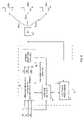
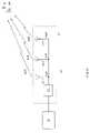
- FIG. 11illustrates an exemplary downlink channel span. While the downlink channel in this context obviously includes the physical medium between the network 10 and the MSs 16 , it further includes at least a portion of the transmission and reception systems in the network transmitters and MS receivers, respectively. Thus, transmit signal pre-compensation may be used to compensate not only for the physical channel propagation characteristics, but for the characteristics of the transmitting and receiving systems as well. Hence, the downlink channel might be more comprehensively referred to as the “transmit channel.”
- the transmitter 42 in a given network BS 12comprises an input filter 41 , an upconverter/modulator 43 , a PA 45 , and antenna 46 .
- the input filter 41filters the I and Q signal samples received from, for example, the transmit processing system 18 . After filtering, these signals drive the modulator 43 , which outputs the modulated RF carrier signal to the PA 45 , which amplifies it to a level suitable for transmission by antenna 46 .
- the BS 12might include a plurality of transmitter resources for simultaneously generating multiple transmit signals.
- FIG. 11represents a simplification in at least some respects.
- the signal transmitted from BS 12is received by a given one of the MSs 16 , which, here, comprises antenna 61 , switch/duplexer 60 , receiver 62 , transmitter 64 and combiner 96 , which might comprise a portion of the baseband processor 66 shown earlier.
- Receiver 62comprises downconverter 91 , filter 92 , and sampler 94 . Together, these elements receive, filter, downconvert, and digitize the received signal to produce a baseband sample stream of I and Q signal samples (I j , Q j ).
- Transmitter 64comprises filter 98 , upconverter (modulator) 74 , and PA 76 . Together, the transmitter elements generate a transmit signal for transmission by antenna 61 .
- signal transmitted from MS 16generally includes loop-back information for determination of downlink channel characteristics by the network 10 .
- the span of the downlink channel—transmit channel—is illustrated as spanning from the I I , Q I sample inputs of the transmit filter 41 at BS 12 to the I j , Q j sample outputs from sample 94 at the MS 16 .
- the span of the uplink channel from MS 16 to network 10is defined similarly as being from the input of samples I J , Q J to the MS transmitter filter 98 to the output the network equivalent of receiver sampler 94 . If, at the MS 16 , received samples from sampler 94 are connected directly into transmit filter 98 , the loop-back channel defined from network 10 to the MS 16 and back is simply the product of the downlink and uplink channels defined above.
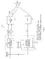
- FIG. 12Aillustrates the various downlink and uplink channel combinations involved for the various loop-back signal components at a given one of the MSs 16 .
- the complex samples transmitted by the network 10pass through the downlink channel 100 as described above, where they are received by the MS 16 .
- Combiner 96 in the MS 16combines the signal received from the network 10 with locally generated pilot signal information, which combined information is then returned by the MS 16 to the network 10 via transmission through the uplink channel 102 .
- the network 10receives complex samples including a component comprising loop-back sample data that has passed through both the downlink channel 100 and the uplink channel 102 , and pilot signal sample data that has passed through only the uplink channel 102 .
- FIG. 12Billustrates that the overall loop channel is unchanged by imagining the order of the uplink and downlink to be reversed.
- the samples that occur between the uplink channel 102 and the downlink channel 100do not correspond with samples that arise in the real situation.
- These “intermediate samples”are however useful in that they allow the network 10 to estimate the downlink channel 100 by comparing, e.g., correlating, the loop-back signals received from the MSs 16 with the calculated intermediate samples.
- Intermediate samplesmay be calculated by the network 10 based on passing the known downlink samples that were input to transmit filter 98 at the MS 16 through an estimated uplink channel 102 ′ as determined from the pilot codes added to the looped-back signal. Such intermediate samples may then be passed through an estimated downlink channel 100 ′ to generate derived samples subjected to the overall estimated uplink/downlink channel information.
- the parent applicationsdisclose an informational deficiency as regards being able to determine more than one downlink channel from a single loop-back signal.
- an informational deficiencywas overcome in the invention of the parent applications by transmitting independent pilot symbol streams to non-existent receivers through fictitious channels, the fictitious channels being chosen such that the pilot symbol streams are nominally not received at the actual receiver when the network has accurate estimates of the downlink channels. That is, the network 10 generated actual and dummy pilot signals, and then adjusted the dummy pilot signals to reduce interference at the single receiver (e.g., MS 16 ).
- the number of such dummy pilot signals requiredis generally equal to the difference between the number of network antennas and the number of receivers. If the number of receivers is greater than the number of antennas, it may be that no pilot transmissions are needed to solve the informational deficiency problem.
- the addition of at least one dummy pilot signalcan substantially reduce the probability of this occurrence, as is explored more fully later herein.
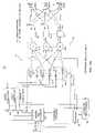
- FIG. 13illustrates another variation on network 10 as regards loop-back processing and transmit signal pre-compensation.
- the network 10includes a network RF transmission system 110 , and a RF receiving system 112 .
- These transmission and reception systemsmay comprise, in some embodiments, one or more BSs 12 , or might comprise discrete transmitter/receiver arrangements.
- the network 10transmits combined transmit signals to MSs 16 —MS 1 , MS 2 , . . . , MSm—through transmission system 110 , and receives loop-back signals from these m MSs 16 via receiving system 112 .
- transmit processing system 18provides transmit signal pre-compensation and loop-back signal processing.
- memory 34is not explicitly shown to avoid overcrowding the illustrated elements.
- pre-compensation processor 30comprises “n” Kalman Trackers 114 , with each Tracker utilizing a 3n ⁇ 3n Kalman “P-matrix,” a matrix pre-combiner 116 , and spreaders/combiners 118 .
- Loop-back processor 32comprises despreaders/combiners 120 , i.e., RAKE receiver resources, matrix combiner 122 , and Inter-Symbol Interference cancellers 124 .
- the illustrated configurationaccommodates a type of loop-back useful in adapting symbol-rate combining for interference pre-cancellation at one or more network transmitters.
- Symbol streams S 1 , S 2 , . . . Sm destined for respective MSs 16are input to matrix pre-combiner 116 , which is a linear matrix combiner operative at the symbol rate to produce symbol-rate combined values X 1 , X 2 , . . . XL for transmission by transmitters and antennas index 1 to n within transmission system 110 .
- the L symbol-rate signalsare spread with respective spreading codes 1 . . .
- Lwhich are not necessarily different, but may be any of the same, different, orthogonal and non-orthogonal codes.
- the outputs of the L spreadersare at a chip rate, which is in general an elevated rate compared to the underlying information symbol rate.
- the L spread signalsmay then be linearly combined using the chip-rate spreaders/combiners 118 to produce n combined outputs for transmission by respective transmitters 1 to n in transmission system 110 .
- Lis equal to the number m of MSs 16 , and the number of transmitters n is one. In another exemplary embodiment, L equals twice m (2m) and the number of transmitters in the transmission system 110 is two.
- the spreaders/combiners 118then combine signals X 1 to Xm for transmission by transmitter ( 1 ) and signals X(m+1) to X(2m) for transmission by transmitter ( 2 ).
- Spreading code(i) in the latter casewould be equal to spreading code(i+m), so that signals destined for MS(i) from either transmitter ( 1 ) or transmitter ( 2 ) are spread with the same code.
- the chip rate combining polynomials in the latter caseare preferably the time-reversed conjugate transpose of the channel polynomials from the relevant transmitter to the relevant receiver. That is, the combining polynomials are formed as time-reversed conjugate transposes of the estimated downlink channels for the transmitters ( 1 ) and ( 2 ) within RF transmission system 110 relative to the MSs 16 .
- the signals transmitted by network 10propagate through multipath channels Cij from antennae) to MS(i).
- MS(i)correlates its received signal with shifts of its assigned CDMA spreading code (i), then combines the correlations with RAKE tap weights to form RAKE combined soft symbols.
- the soft symbolsare then decoded using for example a soft-decision convolutional error correction decoder to reproduce intended information. If the soft symbol values contain too much interference from symbol streams intended for other ones of the MSs 16 , the error correction may not be error-free. Therefore, the network 10 adapts the symbol rate precombining matrix polynomials used by matrix pre-combiner 116 to reduce interference on all of the soft values produced by the RAKE receivers at all MSs 16 .
- the MSs 16typified by MS(i) loop back the RAKE combined soft values to the network 10 so that the network 10 can determine, based on knowledge of the intended symbol streams S 1 to Sm, how much cross-interference is still present at the MSs 16 .
- Each MS 16therefore re-spreads its RAKE receiver soft output values from symbol rate to uplink chip rate using an uplink spreading code assigned to the given MS 16 .
- the MSs 16may add uplink pilot codes to assist the network 10 in determining the uplink channels from the MSs 16 to the network 10 , to facilitate separation of the uplink and downlink channel affects on the loop-back signals. However, this action is not in theory strictly necessary to determine whether a given loop-back signal depends on unintended symbol streams. If an uplink pilot code is not used, the network 10 correlates the signal received from MS(i) with shifts of uplink spreading code(i) and, using knowledge of the intended symbol stream Si for MS(i), RAKE combines the correlations to reproduce a RAKE-combined soft symbol value stream for each MS 16 .
- the network 10may use receive interference cancellation matrices as disclosed in the parent applications to ensure that the signals received from MS 1 to MSm are separated. The separated soft-values are then correlated with symbol streams S 1 to Sm to determine if a given soft value stream contains interference from one or more unintended symbol streams. The network 10 then adjusts the symbol-rate combining matrix polynomials used by matrix pre-combiner 116 to reduce the levels of unintended interference.
- the network 10correlates the signal samples received at antenna(j)—i.e., an antenna within the receiving system 112 —delayed by k chips with uplink spreading code(i) over a soft symbol period and obtains a correlation value Vijk which is the looped-back soft-symbol value from MS(i) multiplied by uplink channel propagation coefficient Cijk, and with additive interference from other soft values associated with other ones of the MSs 16 .
- the soft value stream corresponding to each MS 16may be correlated with the symbol streams intended for the other MSs 16 to determine how much interference exists in each soft value stream from unintended symbol streams. That is, the soft value stream for MS(k) is correlated with the information symbol streams, S(i) where k ⁇ i to determine cross correlation interference between the symbol stream intended for MS(k) and the symbol streams intended for the other MSs 16 .
- the amount of interference between symbol streamsis a complex amount denoted by a complex factor to be determined. If the spreading codes used for transmission to each MS 16 exhibit a constant cross-correlation from one symbol period to the next, this complex amount may be determined by averaging the correlations of separated, looped-back soft-value stream(k) with symbol stream S(i) to obtain an interference polynomial Iik. If the symbol-rate pre-cancellation matrix used by matrix pre-combiner 116 performed perfectly, polynomial Iik would have zero coefficients for i not equal to k. That is, the interference matrix I would be a diagonal matrix of polynomials representing only interference between successive symbols of the same symbol stream. This type of interference, recognizable as Inter-Symbol interference within the same symbol stream does not have to be cancelled by network 10 , as each MS 16 can be equipped with an equalizer to handle ISI after the RAKE combining within the MSs' receivers.
- the network 10can use pilot code correlations to determine uplink channel polynomials, which are then used to determine a receive interference cancellation matrix used by matrix combiner 122 in separating the uplink signals.
- the known pilot codesmay then be subtracted from the separated uplink signals to leave only the loop-back fraction or portion of the signals received by the network 10 from the MSs 16 .
- the loop-back portion of the received signalsis then used by Kalman Trackers 114 as before to determine a cross-interference matrix, the values of which are used to update the symbol-rate pre-cancellation matrix of matrix pre-combiner 116 .
- the cross-interference matrixcan be reapplied to the known downlink transmissions to determine what each MS 16 receives. This information can then be operated on by the previously determined uplink estimates using the pilot codes to determine the loop-back signals received at network 10 . The determined loop-back signal can then be subtracted from the total signal received at the network from a particular MS 16 , leaving only the pilot code information from that MS 16 , from which a better determination of the uplink channel for that MS 16 can be made. The improvement in estimation of the uplink results from having removed interference to the pilot from the loop-back signal by the above process.
- the signals determined to have been received at the MSs 16can be added to the known pilot signals added at the MSs 16 , and the whole used to obtain a better estimate of the uplink channels.
- the pilot codes operated on by the uplink channels from the various MSs 16can be subtracted at the network 10 to remove pilot code interference from the loop-back signals before analyzing them for determination of downlink channel estimates. Either of the above approaches or any variation thereof can then be iterated to the extent allowed by available processing power at the network 10 in order to obtain successively refined estimates of the uplink and downlink channel polynomial matrices.
- received signal samplescan be combined with known pilot symbols and/or uplink information symbols in a variety of ways. That is, the loop-back signal transmitted by each MS 16 may be formed using any number of techniques, or through combinations of selected techniques.
- the MSs 16use linear addition to combine signal information received from the network 10 through the downlink channel with locally generated information, e.g., pilot code information.
- each received signal sampleis added to a corresponding pilot code sample, and the sum is then upconverted and transmitted by the MS 16 . Since both the pilot code information and the original transmissions received by the MS 16 are known to the network 10 , it can separate the combined loop-back signal received from the MS 16 as long as the pilot code and the original transmissions from the network 10 are sufficiently uncorrelated.
- Another exemplary methoduses an alternating approach to loop-back signal formation.
- MSs 16form their loop-back signals by alternating loop-back signal segments with transmissions of pilot code or information-bearing signal segments by time-multiplexing. That is, the return transmission from each MS 16 to the network 10 alternately comprises loop-back of network transmissions and locally generated transmissions.
- the locally generated transmissionsmay comprise pilot code information, may comprise data transmissions (i.e., information bearing transmissions), or some combination thereof.
- Segments of pilot code transmissionpreferably occur sufficiently close in time to segments of loop-back transmission such that the propagation channels between the network 10 and the MS 16 do not change substantially between the two times, or, at least, can be interpolated accurately from one type of symbol to another type of symbol.
- a convenient signal segment size for time-multiplexing between loop-back and locally generated signal transmissions at the MS 16is one such lower-speed symbol time or an integer number of such symbol times.
- a set of samples received at the MS 16is collected over a downlink symbol period and transmitted as a loop-back symbol from the MS 16 , followed by transmission of a symbol of data or pilot code originating at the MS 16 , and then another looped-back downlink symbol and so on, with the pattern repeating.
- Each such symbolcan comprise a fixed number of chips, and the pattern of loop-back and pilot code or data symbols transmitted by the MS 16 need not be strictly alternating, but can be in any pattern agreed upon a priori between the network 10 and the MSs 16 .
- the patternmeets the timing requirement that the uplink and downlink channels are sufficiently unchanged between transmissions of the loop-back signal and the MS's pilot and/or data signal.
- looped-back signalscan be soft symbols formed at the MSs 16 , the soft symbols then being combined with optional pilot symbols and transmitted back to the network 10 .
- the soft symbols in the case of a CDMA implementation of network 10can be the output of RAKE combiners at the MSs 16 , and the soft symbols combined with pilot symbols can be respread by the MSs 16 for transmission back to the network 10 using uplink spreading codes assigned to each of the MSs 16 .
- the uplink pilot symbols transmitted by the MSs 16need not be known symbols, but may be uplink traffic symbols such as digitally coded voice or data traffic.
- Uplink data trafficcould be acknowledgements of receipt of downlink data packets to form a packet acknowledge/request (ARQ) system, for example.
- ARQpacket acknowledge/request
- the network 10estimates uplink channel information based on correlating the signals received at the network 10 with the uplink spreading codes applied by the MSs 16 during the transmission of pilot symbols. Using the estimated uplink channel for a given MS 16 , the network 10 estimates the soft loop-back symbols that were generated by the MS 16 by despreading the uplink signal for the MS 16 , using a RAKE receiver for example, then subtracting uplink ISI using the corresponding one of the ISI subtractors 124 shown in FIG. 10A .
- ISI subtractionis facilitated if soft symbols and pilot symbols are interlaced, so that the ISI from symbols adjacent to the unknown soft symbols results from the known pilot symbols.
- the soft loop-back symbols reproduced in the network 10tell it what the corresponding MS 16 is receiving at the output of MS's receiver.
- These estimated soft symbolsshould comprise only the intended signal for a MS 16 , which will be achieved if the downlink interference pre-cancellation matrix used by matrix pre-combiner 116 is accurate. If there are errors in the downlink interference pre-cancellation matrix however, the soft symbols will contain interference from information symbol streams intended for other mobile terminal receivers.
- the amount of such cross-interferencemay be estimated by correlating the soft symbols estimated for a given one of the MSs 16 with the information symbol streams S(i) intended for the other ones of the MSs 16 .
- An exemplary method for determining the cross-interference between the individual information symbol streams S(i)is to set up and solve a set of simultaneous equations for the unknown interference coefficients.
- the soft symbol SSi,j emerging at instant(i) from MS(j)may be described in terms of the symbol stream S(i,k) transmitted to mobile MS(k) at instant(i) as follows:
- the above implementationmay be used to demonstrate an alternative exemplary method of solving for interference or channel coefficients rather than collecting and then analyzing blocks of signal samples at the network 10 .
- This alternative methoduses the technique of continuous sequential least squares estimation, which enables a refinement to be carried out to a previous set of estimates upon receipt of each new signal sample or loop-back symbol. Thus, it is not necessary to wait for the collection of a minimum block of data in order to obtain a solution for the unknown quantities, providing a previous estimate, however coarse, was already available.
- the Kalman Filteris a suitable sequential least squares algorithm, but other approaches include sequential least squares with exponential de-weighting of older data, or continuous least squares with no exponential de-weighting. All three techniques, abbreviated to Kalman, Exponential Forgetting, and Least Squares Forever respectively, are essentially identical in their mathematical formulations and programming, and differ only in one detail step.
- the general mathematical formulationas applicable to the Kalman process contemplated herein for example, comprises the following steps:
- a navigational analogyillustrates such potential freewheeling, wherein obtaining a new measurement that suggests a position on a given line running NE-SW, which does not run exactly through a previous position estimate.
- the new positionis not uniquely determined by the new measurement alone, but a best update of the position involves moving from the old position along a perpendicular dropped to the given NE-SW line, which conforms the position to the new measurement with the least change from the old position.
- This approachcauses minimum disturbance to the coordinates in the planes not determined by the new measurement.
- moving along a perpendicular towards the new constraint lineis not always optimum, depending on how “stiff” the previous solution was in latitude and longitude respectively.
- the above approachrecords such “stiffness” of previous solutions in the P-matrix of the above formulation, which thus determines the best direction in which to move the old interference cancellation solution to obtain a refined interference cancellation solution.
- the transmit interference pre-cancellation matrix used by matrix pre-combiner 116is updated by Kalman Trackers 114 in such a way as to drive the off-diagonal polynomials of the interference matrix I towards zero, thereby improving the cancellation of interference between symbol streams intended for different MSs 16 .
- individual information symbol streams S 1 , S 2 , . . . Smare intended for transmission to respective ones of the plurality of MSs 16 , MS 1 , MS 2 , . . . MSm.
- the symbol streamsare combined in interference pre-cancellation matrix pre-combiner 116 to produce mixed sample streams X 1 , X 2 , . . . XL, which are still at the symbol rate.
- Mixed sample Xk at instant iis denoted by Xk(i) and depends on S 1 (i) . . . Sm(i) and also on S 1 (i ⁇ 1) . . . Sm(i ⁇ 1) as well as S 1 (i+1) .
- Spreaders/combiners 118then multiply the mixed sample streams by respective spread-spectrum codes for transmission to the MSs 16 .
- the spread-spectrum codesmay be orthogonal codes such as those selected from a Walsh code set scrambled with a common, multiplicative, complex scrambling sequence. Non-orthogonal spreading codes also may be used.
- the output of spreaders/combiners 118is applied to transmission system 110 , which, as noted earlier, can include a single antenna at a single site; diversity transmission using cross-polarized antennas at the same site, or diversity transmission using multiple antennas at different sites, as described herein and in the parent applications.
- Transmit processing system 18may be extended such that transmission system 110 includes chip rate pre-filtering to optimize or otherwise improve transmission efficiency by directing transmit signals to particular ones of the MSs 16 through the lowest loss downlink channel(s).
- FIG. 14illustrates exemplary details for the MS 16 similar to those shown earlier in FIGS. 7A and 11 , for example.
- the MS receiver 62explicitly includes RAKE receiver resources. More particularly, receiver 62 in this exemplary embodiment includes receiver/downconverter resources 130 and despreading/RAKE combining resources 132 .
- MS 16receives a composite received signal from the network 10 , which it processes, despreads, and RAKE combines to produce soft output values representative of the information symbols specifically intended for that MS 16 , allowing, of course, for some amount of interference from the unwanted signals and other interference within the composite received signal.
- duplexer/switch 60comprises a duplexer to isolate transmit and receive frequencies on the MS antenna 61 ; where MS 16 alternates between transmission and reception, duplexer 60 might simply comprise a switch operative to alternately connect the receiver 62 and transmitter 64 with the antenna 61 .
- the soft output values obtained at the output of the despreading/RAKE combining resources 132are available for loop-back to the network 10 .
- a summer 72might be used to combine the soft symbols with pilot and/or data symbols generated locally at the MS 16 .
- the soft symbol valuesare obtained based on receiver/downconverter resources 130 amplifying, downconverting, and digitizing the received composite signal to generate a stream of complex numbers.
- De-spreading/RAKE combining resources 132multiplies these complex samples by a locally generated despreading code or codes corresponding to the code or codes used for spreading at the network 10 .
- the despreader/RAKE combiner resources 132average the resultant product over each symbol period to produce symbol-rate despread sample streams.
- RAKE receiver operationsdiffer from conventional RAKE receiver processing in that the MS 16 loops back soft output values obtained by RAKE combining at the MS 16 . That is, the despreading/RAKE combining resources 132 provide soft output values (soft symbols) for error-correction decoding by a soft decoder (not shown, but may be part of baseband processor 66 ), as well as providing the determined soft symbols for looping back via the transmitter 64 .
- the MS 16may combine, using summer 72 for example, known pilot symbols or other locally generated information with the soft symbol output from the receiver 62 . Such combining may, as noted earlier herein, involve linear combining and/or time-multiplexed combining. With a time-multiplexing approach, the MS 16 does not necessarily multiplex all soft symbols with pilot symbols, but only a sufficient number to allow network 10 to determine cross-interference between the different symbol streams intended for the MSs 16 from the loop-back symbols.
- one method of additively combining pilot symbols with soft symbolsadds a pilot symbol value (which may be real or complex) to a complex soft symbol value on a one for one basis, i.e. the pilot symbol stream is time-aligned with the soft-symbol stream.
- a pilot symbol valuewhich may be real or complex
- the pilot symbol streamis time-aligned with the soft-symbol stream.
- certain advantagesmay obtain from adding the pilot symbol stream to the soft-symbol stream with a half-symbol time offset, so that the same pilot symbol adds to the last half of one soft symbol and the first half of the next.
- the network 10uses correspondingly offset integration periods when correlating the loop-back signal to despread the soft symbols as compared to despreading the pilot symbols.
- Waveform Ais obtained by linearly adding soft symbol values to pilot symbol values that are time-aligned with the soft-symbol periods.
- Waveform Billustrates linear addition of the soft-symbol values to pilot code symbols shifted to the left by half a symbol period.
- Waveform Cillustrates the result of alternately time-multiplexing a soft-symbol with a pilot symbol to produce a loop-back symbol stream of double the underlying symbol rate. If the symbols are complex, as is the case generally, the real-value combining illustrated in FIG. 15 applies likewise to combining the corresponding imaginary values.
- loop-back signal variationsare possible, such as time-multiplexing only half the soft symbol values with half as many pilot symbol values per unit time in order to maintain a combined symbol rate equal to the original soft-symbol rate.
- Other variationscan comprise linear addition of a pilot symbol stream that is of a different symbol rate than the soft symbol stream rate, or multiplexing two out of every three soft symbols with one pilot symbol every three symbol periods, or other such combinations.
- the network 10can, for a given MS 16 , improve estimation of both uplink and downlink channels by the following iterative methods:
- the uplink symbols originating at a given MS 16are not known pilot signals but rather unknown uplink traffic symbols that the network 10 must decode
- removal of the loop-back signal interferencereduces errors in decoding the uplink traffic symbols.
- Such interference removalmay be based on the network 10 remembering what it transmitted on the downlink for comparison with returned loop-back signals corresponding to those remembered transmissions. Variations of such methods can be used where the MS 16 forms its loop-back uplink transmission either by combining samples directly from the received composite signal (i.e., non-despread downlink values) with pilot code samples, or by combining de-spread soft symbol values with pilot symbol values.
- the time-multiplexing method of combining received downlink signals with pilot signalsis used by the MS 16 , such as shown in Waveform C of FIG. 15 , there is much reduced interference between pilot and downlink signals, except for the effect of multipath smearing at the edges of the symbol period. If desired, the above subtraction method can still be used to remove the residual smearing effect.
- the combined symbolsare respread using an uplink spreading code in spreader 134 of MS transmitter 64 .
- the uplink spreading code timingis generally given a predetermined alignment with the soft symbols and the pilot symbols so that the network 10 knows a priori where symbol boundaries lie.
- the re-spread combined symbols output by the spreader 134are upconverted to a transmit frequency by up-converter 136 , and then amplified to a transmit power level by transmitter PA 138 for transmission as the loop-back signal back to the network 10 .
- the network 10receives signals from the m MSs 16 in receiving system 112 , which may comprise one or more receiving antennas at one or more sites. These received signals are filtered, amplified, downconverted, sampled and digitized to produce streams of complex numbers for despreading and separation of the loop-back signals from the different MSs 16 .
- One method of enhancing separation of the loop-back signals received from multiple MSs 16appears in FIG. 13 , which method may be termed “post-RAKE interference cancellation.”
- the complex sample streams output from receiving system 112are despread by despreader/RAKE combiner 120 using shifts of the corresponding uplink spreading codes used by respective MSs 16 to produce despread streams.
- the despread streams corresponding to different timing shifts, i.e. to different multipath rays,are then weighted with multipath channel coefficient estimates and RAKE-combined.
- the RAKE combiningmay also include combining signals de-spread from multiple receive-system antennas, i.e. diversity combining.
- the diversity-combined symbolsmay comprise diversity combined pilot symbol streams from which the uplink channels are estimated, and looped-back soft symbol streams from the MSs 16 .
- the pilot symbols used by the MSs 16are known to the network 10 and may be subtracted or gated out of the RAKE combined sample streams.
- the RAKE combined soft sample streamsalso may comprise some mutual interference between signals looped back from the different MSs 16 .
- Such loop-back signal interferencecan be removed by application of the post-RAKE interference cancellation matrix to the loop-back symbol streams in interference-cancellation matrix combiner 122 .
- Such interference cancellationinvolves multiplying the loop-back symbol streams by the inverse or adjoint of a cross-coupling matrix derived from uplink channel estimates and correlations between the known uplink codes (both of which may be time-variable from one symbol period to the next).
- Such post-RAKE interference cancellationmay leave Intersymbol Interference between adjacent looped back symbols un-cancelled within the obtained soft output value streams output by the interference cancellation combiner 122 .
- ISI subtractors 124subtract this ISI using estimates of uplink channels and the autocorrelation of each spreading code. ISI subtraction can be equated with equalizing when the post-RAKE interference rejection employed by the network 10 uses the adjoint rather than the inverse of the cross-coupling matrix.
- the difference between the adjoint versus the inverse matrix approachis that omission of division by the cross-coupling matrix determinant (an IIR filter) in the case of the adjoint matrix leaves ISI uncompensated.
- dividing by a reduced determinantleaves some ISI un-cancelled due to some poles being omitted from consideration by virtue of using the reduced determinant.
- ISI subtraction as implemented by ISI subtractors 124represents an ill-conditioned process due to determinant roots near the unit circle, it is possible instead to adapt the Kalman Trackers 114 to process looped back symbols with known ISI. Regardless, the principle of Kalman Tracker operation is the same, namely, to predict the looped back soft symbols for the MSs 16 using the current values of parameters that the included Kalman filters are supposed to be tracking; to compare these predicted values with actual values observed at the outputs of the ISI subtractors 124 (or directly from interference-cancellation combiner 122 ); and then refine the tracked parameters in such a direction as to better approximate the observed values.
- Kalman Trackerwithin Kalman Trackers 114 to process each signal looped back from a corresponding MS 16 , and each Tracker tracks 3n residual interference coefficients, giving 3 n 2 coefficients representing n 2 3-coefficient polynomials.
- the order of these polynomialsdepends on how the extent of neighboring symbol interference for each symbol(i) at each MS 16 . If more than the immediately adjacent symbols have an effect on the current symbol(i), the polynomial order would be greater than 2, for example 4 (for five coefficients), and each Kalman Tracker at the network 10 would then track 5n parameters.
- the estimated residual interference coefficients output from the Kalman Trackers 114are used to refine the coefficients of the interference pre-cancellation matrix polynomials that form the interference cancellation matrix used in the matrix pre-combiner 116 such that each MS 16 receives only its intended symbol stream with insignificant interference from symbol streams intended for other MSs 16 .
- the presumption that these coefficients are relatively constantmust be true. If the effective averaging time of the Kalman filters used by Kalman Trackers 114 is more than one symbol period, then the downlink channels must not change significantly over that number of symbol periods; nor may the cross-correlation between downlink codes used to spread the various signals transmitted from the network 10 vary from symbol period to symbol period. The latter requirement is satisfied if the same spreading code chip block is used to spread each successive symbol of the same symbol stream. Using time-varying downlink spreading codes that exhibited constant autocorrelation and cross-correlation properties would also satisfy the requirement.
- the Kalman Trackers 114are made responsive to changes in interference at the MSs 16 arising from changes in the downlink channels between the network 10 , while being isolated from those changes arising in cross-correlation variations arising from dynamically changing downlink spreading codes.
- Crepresents the RAKE tap weightings used in a given one of the MSs 16 , which are based on downlink channel estimates made by that MS 16 . These values are more or less smoothed versions of the instantaneous downlink channel values C k (t).
- the network 10can employ a standard model representing how the MS 16 derives these smoothed RAKE tap weights, the model allowing the C values to be computed at the network 10 given a history of network-estimated Ck(t) values prior to the current time instant “t.”
- H j (t)The coefficients H j (t) are totally known from the spreading codes and information symbol streams transmitted by the network 10 .
- H j (t)simply represents the correlation over the symbol interval “t” between the code segment used for that symbol and the sum of everything transmitted from the network antenna, i.e., the composite CDMA signal, with a relative shift of “j” chips.
- These valuescan be formed in real time by the network 10 , to obtain a sequence of H-values at the information symbol rate, using each MS's code, the H-values being passed to the Kalman Trackers 114 for the respective MS 16 .
- the above equationexpresses the expected loop-back soft symbol value as a linear function of the values C k (t) to be estimated, if C i # (t) are considered to be known. Therefore, the above expression is a suitable formula for predicting the loop-back value for Step 2 of the above-described Kalman process.
- the Kalman processproceeds by using the appropriate correlations H, computed for each symbol period anew, to explain the systematic variation in the loop-back value due to changing downlink spreading codes, thus leaving only the unknown channel variations to be tracked by the Kalman Trackers 114 .
- the standard model employed by the network 10 for deriving RAKE tap weightsis used to update the values C i # (t).
- the network 10might not receive soft output values as part of the loop-back signals from the various MSs 16 , but rather might derive such information based on processing loop-back samples of the composite signals received at the MSs 16 based on the network's models of the receivers 62 used in the MSs 16 .
- the standard RAKE model used by network 10can be different for each MS 16 .
- the types of MSs 16 involved in the transmit pre-compensation schemeare known to the network 10 based on a number of approaches.
- the network 10interrogates the MSs 16 to obtain “classmark” information, which the network 10 then relates to RAKE tap models in a repertoire of RAKE tap models stored against classmarks in the network 10 .
- the network 10obtains such information from a database of information relating to the particular subscriber and accessed by mobile telephone number “MIN” (Mobile Identification Number) or “IMSI” (International Mobile Subscriber Identification), or from a database of MS characteristics accessed by the MSs' ESN (Electronic Serial Numbers).
- MINMobile Identification Number
- IMSIInternational Mobile Subscriber Identification
- the latter approachmay be more appropriate when the IMSI relates to a “smart card” or other intelligent peripheral rather than to a particular mobile phone (i.e., MS 16 ).
- a known model of the method used by the mobile terminal to derive RAKE tap weights from channel estimatesmay alternatively be used in a non-linear Kalman filter formulation.
- the exemplary embodiments of network 10as a multiple-input, multiple-output (MIMO) system, discussed above illustrate that performance on the downlink can be improved through the use of MS feedback. That is, transmit signal pre-compensation may be performed by the network 10 to, among other things, improve transmission efficiencies and reduce interference at the MSs 16 . Such pre-compensation processing is based on the network's knowledge of downlink channel conditions as acquired by processing loop-back signals from the MSs 16 . The discussion now turns to additional exemplary approaches directed to formulation of downlink channel information at the MSs 16 for return transmission to the network 10 .
- MIMOmultiple-input, multiple-output
- transmit signal pre-compensationuses mobile-estimated downlink channel state information received at the network 10 via loop-back signaling by the involved MSs 16 .
- This mobile-estimated approach to determination of downlink channel informationinvolves the MSs 16 formulating loop-back information as specifically-defined bit sequences from which the network 10 re-constructs downlink channel state information that may then be used in transmit signal pre-compensation as generally described above.
- each MS 16transmitting bit sequences whose structure is known a priori to the network on a reverse channel, wherein the bit sequences represent downlink channel state information as estimated by the MSs 16 .
- the network 10might, within a given network service area in which a particular group of one or more MSs 16 are operating, define a common feedback channel (CFC) as a shared reverse link on which the MSs 16 in that group transmit loop-back information in the specified format.
- CFCcommon feedback channel
- the MSs 16may use that existing reverse link; hence, implementing the method does not require any change to the architecture of existing MSs 16 .
- Such digital reverse linksare defined by essentially all of the existing and developing wireless communication standards.
- An exemplary embodiment of the mobile-estimated methoddefines a common feedback channel (CFC) per site or individual sector of network service coverage, and all MSs 16 within that site can share the CFC for feeding back their channel state information to the network 10 .
- CFCcommon feedback channel
- simulations of this approachdemonstrate that the power dedicated to the CFC can be of the same order as the power currently dedicated to one voice channel on the reverse link of the WCDMA standard. For example, assuming four network transmit antennas, which may be co-located at a given BS 12 supporting the network area of interest, and further assuming one receive antenna at a given MS 16 , simulations indicate transmit pre-compensation performance within 1 dB of that obtainable with perfect downlink channel knowledge.
- the network 10schedules sharing of the CFC resource between individual mobiles in a group of MSs 16 . That is, the MSs 16 in the group share the CFC as a common reverse link channel in TDMA fashion, with the network 10 scheduling use of the CFC by each MS 16 .
- each MS 16estimates its downlink channels, and the resulting estimated channel coefficients are converted, in a manner described more fully later herein, to a sequence of 2 ⁇ P ⁇ B bits, where P and B are design parameters. Any subsets of these 2 ⁇ P ⁇ B bits can be used by the network 10 to reconstruct the original downlink channel coefficients (naturally, the larger the number of bits used for this reconstruction, the better the quality of the resulting reconstruction).
- multiple MSs 16share a common downlink channel in TDMA fashion.
- the IS-856 standarddefining a High Data Rate packet service using CDMA, is a notable example of such a scheme.
- the network 10schedules the MSs 16 on the downlink channel such that each is served according to a desired scheduling scheme, such as according to a proportional fairness scheduling algorithm.
- the network 10may request that the next-scheduled MS 16 report feedback information to the network, i.e., report current downlink channel estimates to the network 10 .
- the network 10can apply transmit signal pre-compensation to the signals transmitted to the reporting MS 16 during the scheduled service to that MS 16 .
- the network 10can schedule which MSs 16 report feedback information to it on the time-shared CFC based on its scheduling of forward link service to the MSs 16 .
- FIG. 16illustrates the use of multiple antennas 46 - 1 , 46 - 2 , and so on, at a given network BS 12 ; however, a single antenna 46 with multiple transmitting elements may be used as well.
- antennas 46 - 1 through 46 -Mtransmit signals to a given MS 16 , denoted as MS 1 .
- the MS 1includes one receive antenna 61 .
- M network antennasare used to transmit to a MS 16 having one receive antenna. It should be noted that the same method can be applied to the case with multiple receive antennas at the MS 16 (i.e., the method applies where spatial diversity is employed at the receiver).
- FIG. 16there are Mdownlink channels from the BTS to MS 1 , and the medium part of the channel from the m-th transmit antenna of the M transmit antennas to MS 1 has an impulse response g m (t) in the continuous-time domain. Given a sampling interval Ts at the mobile receiver, one can model the m-th downlink channel as,
- Each MS 16can form an estimate of its own g m (t) according to:
- T Sthe sampling interval
- T sthe sampling interval
- the sampling interval T scould be less than one chip duration. Note that the “Q” index value in Eq. 9 is not necessarily the same as the “K” index value in Eq. 8.
- each estimated ⁇ m (t)can be conceptually associated with a discrete-time finite impulse response filter with Q non-zero coefficients, i.e.,
- an exemplary embodiment of mobile-estimated channel feedbackforms a scalar-valued sequence s[n] from the ⁇ m [n]'s according to:
- the p m [n] 'sare independent, real-valued, pre-determined, pseudo-random sequences.
- the sequencesmay be i.i.d. samples uniformly distributed between [ ⁇ 1,+1].
- the two sequences ⁇ b R [n] ⁇ n ⁇ 1 P and ⁇ b I [n] ⁇ n ⁇ 1 Pconstitute a digital representation of the M ⁇ Q non-zero coefficients and the Q delays of the estimated downlink channels, as estimated by the MS 16 .
- the MS 16transmits the 2 ⁇ P ⁇ B bits to the network 10 using the digital reverse link.
- these 2 ⁇ P ⁇ B bitsare detected (for example, using a RAKE receiver if direct spread CDMA is used on the reverse link).
- the detected versions of the received b R [n] at the network 10are denoted as ⁇ circumflex over (b) ⁇ R [n] and the detected versions of the b I [n] are denoted as ⁇ circumflex over (b) ⁇ R [n].
- the network 10Given knowledge of the sequences p m [n]'s at the network 10 , the network 10 can estimate ⁇ m [n] from ⁇ circumflex over (b) ⁇ R [n] and ⁇ circumflex over (b) ⁇ I [n].
- the network 10models the ⁇ [n]'s according to:
- the networkmay form ⁇ tilde over (g) ⁇ m [n] as the solution to the following optimization problem:
- the network 10may use those determined estimates to configure transmit pre-compensation.
- the network 10may form the complex conjugates of the estimated channel impulse responses, and use these conjugate values to configure the transmit pre-filters 88 as are shown, for example in FIG. 10A .
- transmit pre-compensation schemesmight employ the determined downlink channel coefficients, and the above exemplary procedure for determining the mobile-estimated downlink channel estimates at the network 10 outlined above is not limited to the particular filtering configurations depicted in the various illustrations.
- the MS 16may separately report the estimated downlink path delays to the network 10 , which, in some respects, can simplify the network's optimization-based approach to determining the mobile-estimated downlink channel coefficients.
- FIG. 17illustrates an exemplary approach to representing downlink channel path delays by a simple bit map on a grid with spacing T s .
- the final estimate of the non-zero coefficients of the downlink channels(i.e., the solution to the optimization of Eq. 17) may then be formed according to:
- a _ ⁇( R T ⁇ R ) ⁇ R _ - 1 ⁇ R ⁇ ⁇ s _ ⁇ . ( 21 )
- the above channel state informationgenerally is developed for a plurality of MSs 16 , all providing downlink channel state information to the network 10 .
- the CFC defined for a given network area or sectormay be shared in TDMA fashion by a plurality of MSs 16 , such that each MS 16 uses the CFC for allocated periods or as otherwise commanded by the network to return downlink channel state information to the network 10 .
- the network 10schedules usage of the CFC by the MSs 16 “on-the-fly.” In at least some embodiments, such CFC scheduling is driven by the downlink scheduling performed by the network 10 .
- a given plurality of MSs 16simultaneously receive downlink traffic on a given channel (e.g., assigned frequency).
- a given channele.g., assigned frequency
- individual ones in a group of MSs 16share a common downlink channel, which is assigned in TDMA fashion to selected ones of the MSs 16 . That is, a single downlink traffic channel from network 10 to a defined group of MSs 16 is divided into timeslots and, generally, only one of the MSs 16 in the group receives downlink traffic in any given timeslot.
- the High Data Rate (HDR) extensions of IS-2000, described in TIA/EIA/IS-856 standard, and the High Speed Downlink Packet Access (HSDPA) mode of WCDMAare examples of such shared downlink traffic channels. Where the network 10 uses shared downlink traffic channels, the network 10 schedules which MSs 16 receives data on which downlink timeslot.
- the network 10Prior to transmitting data to a particular MS 16 on the downlink channel, the network 10 requests that the particular MS 16 transmit loop-back information (i.e., requests that it feed back bit sequences b R [n] and b I [n] on the CFC), or other designated uplink channel.
- the CFCmay be divided into timeslots, with the network 10 requesting particular ones of the MSs 16 to transmit loop-back information at particular times on the CFC.
- the network 10might define multiple CFCs corresponding to different service areas, and thereby received loop-back information for different pluralities of MSs 16 on each of the CFCs. Such arrangements might use a common transmit processing system 18 and associated network transmitters 42 , or might use different such entities to support the different groups of MSs 16 .
- timeslot configuration of the CFCmay be made consistent with the particular air interface(s) used by the network 10 . For example, if network 10 is based on WCDMA standards, the basic 0.66 millisecond timeslot of WCDMA may be adopted for the CFC. Similarly, received signal quality measures defined for other traffic channels may be used as a reference for setting CFC transmit power.
- MS transmit power for CFC transmissionsis set such that approximately the same SNR is achieved at the BS 12 for received CFC transmissions as for the uplink voice channels.
- the power transmitted by each MS 16 associated with a given CFCis controlled so that an SNR of ⁇ 16 dB is maintained at the network's receiver.
- each network transmit antennauses a single receive antenna.
- the downlink channel from each network transmit antenna to each MS 16is modeled as a CASE-3 channel (i.e., each downlink channel has 4 independently fading, chip-spaced rays with strengths 0, ⁇ 3, ⁇ 6, and ⁇ 9 dB).
- a pilot signalis transmitted on each network transmit antenna at the BS 12 , and 25% of the total power transmitted from the BS is devoted to these pilot signals.
- BPSKBinary Phase Shift Keying
- the network 10detects these transmitted bits where the power transmitted by each MS 16 on the CFC is controlled so that the SNR at BS 12 is maintained substantially at the target value. From the detected bits for each MS 16 , the network 10 generates an estimate of the downlink channel coefficients seen by each MS 16 . These estimated downlink channel coefficients are then used by the network 10 to create a bank of matched filters. In an exemplary embodiment, one matched filter is created for each of the M network transmit antennas 46 at BS 12 .
- the bank of matched filtersmight, in some embodiments, be implemented in transmit processing system 18 , as in the pre-filters 88 shown in FIG. 10A for example. However, as was noted earlier, other filtering configurations might use the mobile-estimated downlink channel information.
- the bank of matched filtersmight be implemented in signal processing resources directly in the BS 12 .
- this latter possibilityillustrates the inherent flexibility regarding implementation of transmit signal pre-compensation in the context of the present invention. That is, the transmit signal pre-compensation may be consolidated in transmit processing system 18 for example, or some or all of the functionality of that entity may be distributed across various elements within network 10 .
- implementation of the above matched filtersessentially creates a new single-input/single-output (SISO) channel between the BS 12 and each of the involved MSs 16 .
- SISOsingle-input/single-output
- this SISO channelresults in a certain data rate that can be reliably transmitted to the MS 16 from the BS 12 .
- the network 10develops estimates of the downlink channels based on the loop-back information comprising, in this embodiment, mobile-estimated downlink channel state information, returned by the MSs 16 , its knowledge of the downlink channel(s) is something less than perfect.
- SNRblock error rate
- SNRis defined as the total power transmitted from all the transmit antennas at the BS 12 divided by the power of the thermal noise at the MSs' receivers (where such noise is band limited by the receiver filtering).
- the mobile-estimated approachrepresents only one of a number of exemplary embodiments described herein. More generally, the present invention discloses various approaches to loop-back signal generation at one or more MSs 16 , and subsequent transmit signal pre-compensation by the network 10 supporting communication with those MSs 16 based on downlink channel information obtained from processing the loop-back signals at the network 10 .
- a MS 16may form such the loop-back signal by linearly combining samples of its composite received signal with locally generated pilot and/or data samples, or may form the loop-back signal based on time-multiplexing received signal samples with locally generated samples (pilot and/or data), or may send loop-back information on a different code channel or frequency.
- the combination of such loop-back and locally generated samples in the loop-back signalpermits the network 10 to strip out the effects of the uplink channel, leaving it able to determine the downlink channel characteristics, which determination provides the network 10 its basis for pre-compensating its transmit signals for the downlink.
- pre-compensationmay be performed at the information symbol rate, as where the network 10 determines cross-coupling between the combined information streams it transmits, and pre-compensates the individual streams for such downlink-channel induced cross-correlations.
- the network 10performs pre-compensation at the transmission modulation rate, e.g., chip rate processing, in which case it adjusts the coefficients in its transmit pre-filters based on its estimated downlink channel characteristics.
- Transmit-rate pre-compensation processinggenerally requires MSs 16 to loop back samples essentially taken directly from their received signals
- symbol-rate processinggenerally requires them to loop-back processed received signal samples (e.g., de-spread soft symbol values).
- the MSs 16loop back received signal samples, and the network 10 estimates the processed samples that would have been obtained by the MSs 16 , based on modeling their receiver processes.
- Still other exemplary embodimentsshift, at least to some extent, downlink channel state estimation to the MSs 16 , such that the loop-back signal is formed as a special sequence of bits from which convey channel estimation information to the network 10 .
- the network 10uses the mobile-estimate downlink information obtained from the MSs 16 to configure its transmit signal pre-filtering as a set of matched filters intended to compensate for the expected effects of the downlink channels between it and the MSs 16 .
Landscapes
- Engineering & Computer Science (AREA)
- Computer Networks & Wireless Communication (AREA)
- Signal Processing (AREA)
- Power Engineering (AREA)
- Quality & Reliability (AREA)
- Mobile Radio Communication Systems (AREA)
Abstract
Description
- “Interference Cancellation in a CDMA Receiving System,” application Ser. No. 09/945,002, filed Aug. 31, 2001;
- “Communications System Employing Non-Polluting Pilot Codes,” application Ser. No. 09/915,895, filed Jul. 26, 2001;
- “Communication System Employing Transmit Macro-Diversity,” application Ser. No. 09/915,896, filed Jul. 26, 2001; and
- “Communication System Employing Channel Estimation Loop-Back Signals,” application Ser. No. 09/939,006, filed Aug. 24, 2001.
Further, this application explicitly incorporates by reference herein the disclosure in its entirety from each of the above-named applications.
- (a) the signals {r1[m], . . . ,rn[m]} received at the
network 10; - (b) the network's known transmitted signals {x1[m], . . . ,xn[m]}; and
- (c) the pilot signals
p 1[m]transmitted by theMSs 16.
- (a) the signals {r1[m], . . . ,rn[m]} received at the
- 1. Using the known uplink pilot signal,
p 1[m], thenetwork 10 jointly estimates all the uplink channels {d11[m], . . . ,dn1[m]} from the received signals {r1[m], . . . ,rn[m]}. A variety of estimation techniques may be used for this purpose, as are well understood by those skilled in the art. - 2. The
network 10 forms an estimate of the intermediate signals {s 1[m], . . . ,s n[m]} shown inFIG. 5 . The estimate fors n[m] is simply the convolution of xi[m], which is known to network10, with the estimate of uplink channel di1[m] obtained in Step (1) above. - 3. Lastly,
network 10 jointly estimates the downlink channels {c11[m], . . . ,cn1[m]}, i.e., estimates one or more downlink channel parameters, using the estimates of the intermediate signals, {s 1[m], . . . ,s n[m]} and the uplink received signals {r1[m], . . . ,rn[m]}. In this estimation, {s 1[m], . . . ,s n[m]} serve as a set of known pilot signals. That is, given {s 1[m], . . . ,s n[m]}, the signals {r1[m], . . . ,rn[m]} received atnetwork 10 are a linear function of the downlink channel taps {c11[m], . . . ,cn1[m]}, and a variety of well-known estimation techniques can be used for jointly estimating the downlink channel characteristics {c11[m], . . . ,cn1[m]} from {r1[m], . . . ,rn[m]}.
- 1. Using the known uplink pilot signal,
where {right arrow over (c)}i1is a vector of non-zero taps of ci1[m], {right arrow over (w)}iis a vector representing all other sources of interference and noise at the i-th network receive antenna, and Ai1is a convolution matrix whose entries only depend on {
An estimate of vector {right arrow over (c)}1can be obtained as {right arrow over (c)}1estimate=(B1HB1)−1B1H{right arrow over (r)}, where B1His the Hermitian of matrix B1.
- 1. INITIALIZATION: Assuming there are M parameters to be estimated, there is an M×M matrix denoted by P which is initialized to a large diagonal matrix. The initial parameter values may be set to some intuitive starting point. For example, for interference coefficient estimation, it may be assumed initially that I−1+1(j,k)=0, and that Io(j,k)=0 for j not equal to k (i.e. that there is no Intersymbol Interference and no cross-interference) and that Io(j,j) equals the mean magnitude of looped back soft symbol streams) from MS(j). In the current problem, M=3N and comprises the 3N values of IL(j,k) for a particular value of j and the 3 values of L and the N values of k. There are N separate instances of
steps 1 to 8 with N separate P-matrices, corresponding to eachMS 16, i.e. each separate value of “j”. - 2. PREDICTION: Using the known transmitted symbol streams and the current best estimate of the interference matrix, the
network 10 predicts what the value of the next looped-back soft symbol should be. - 3. ESTIMATION: The
network 10 determines an estimate of the actual value of the looped back soft symbol from the loop-back signal received at thenetwork 10, using uplink channel estimates as described earlier. - 4. COMPUTATION: The
network 10 computes the error E between the soft symbol predicted inStep 2 and the “measured” soft symbol from Step 3. - 5. MODIFICATION: The
network 10 modifies the estimates of the subset of 3N I-matrix values in such a direction as to reduce what the error calculated in Step 4 would have been, using the formula,
Inew=Iold−E.P.G/(1+G#PG) (4)- where Inew and Iold are column vectors of the 3N updated and previous values of the I-matrix values; P is the associated 3N×3N Kalman matrix in
Kalman Tracker 114; G is a column vector of 3N values, which is the gradient of error E with respect to each I-value. The G-values may be deduced bynetwork 10 based on differentiating the equation for the soft symbol SSi,j given above with respect to each I-value in turn, which yields the coefficient of each I-value, namely the associated symbol of a symbol stream. Thus the Gradient vector is:- S(i−1,1)
- S(i,I)
- S(i+1,1)
- S(i−1,2)
- S(i,2)
- S(i+1,2)
- S(i−1,N)
- S(i,N)
- S(i+1,N)
- where Inew and Iold are column vectors of the 3N updated and previous values of the I-matrix values; P is the associated 3N×3N Kalman matrix in
- 6. REDUCTION: The
network 10 reduces the determined P-matrix using the formula
P<=P−PGG#P/(I+G#PG) (5) - 7. MODIFICATION: Increase the P-matrix by either
- Adding a Q-matrix, usually diagonal (for Kalman), or -Multiplying the elements of P by a constant greater than unity (for Exponential Forgetting);
- or, -for “Least Squares Forever”, the P-matrix is not changed in this step, but allowed to collapse forever with successive reductions at step (6).
- 8. REPETITION: The
network 10 repeats fromStep 2 to process each new loop-back symbol.
In the above steps, all quantities can be complex numbers and the superscript # denotes the conjugate transpose. Further, the P-matrix has Hermitian symmetry and at Step 6 only half of the off-diagonal values of P need be updated, e.g. the upper triangular half, and the remainder of P's values set equal to their complex conjugates. This procedure compensates for rounding errors in such algorithms, which errors allows growth of a non-Hermitian error part within matrix P unless P is forced by this error compensation measure to remain Hermitian.
- 1. INITIALIZATION: Assuming there are M parameters to be estimated, there is an M×M matrix denoted by P which is initialized to a large diagonal matrix. The initial parameter values may be set to some intuitive starting point. For example, for interference coefficient estimation, it may be assumed initially that I−1+1(j,k)=0, and that Io(j,k)=0 for j not equal to k (i.e. that there is no Intersymbol Interference and no cross-interference) and that Io(j,j) equals the mean magnitude of looped back soft symbol streams) from MS(j). In the current problem, M=3N and comprises the 3N values of IL(j,k) for a particular value of j and the 3 values of L and the N values of k. There are N separate instances of
- 1. Estimate uplink channels by correlation of the loop-back signal with the added pilot code.
- 2. Apply the estimated uplink channel to the pilot code to obtain a pilot subtraction sequence and subtract the pilot subtraction sequence from the loop-back signal to obtain a pilot-free loop-back signal.
- 3. Apply the estimated uplink channel to the known downlink transmitted symbol stream to obtain a sequence for correlating with the pilot-free loop-back signal to obtain downlink channel estimates.
- 4. Apply the estimated downlink and uplink channels to the known downlink transmitted symbol stream to obtain a downlink subtraction sequence and subtract the downlink subtraction sequence from the loop-back signal to obtain a downlink-free loop-back signal.
- 5.
Repeat step 1 using the downlink-free loop-back signal in place of the original loop-back signal to obtain improved uplink estimates. - 6. Iterate from
step 2 using the improved uplink estimates until no further significant improvement is obtained.
SSu(t)=Ci#(t)·Hi−k(t)·Ck(t) (6)
Gk=Ci#(t)·Hi−k(t), (7)
with implied summation over the index i. Thus, the Kalman process proceeds by using the appropriate correlations H, computed for each symbol period anew, to explain the systematic variation in the loop-back value due to changing downlink spreading codes, thus leaving only the unknown channel variations to be tracked by the
Each
where TS, the sampling interval, is used to quantize the delays τk's. For example, in a wireless system employing direct spread CDMA on the downlink, the sampling interval Tscould be less than one chip duration. Note that the “Q” index value in Eq. 9 is not necessarily the same as the “K” index value in Eq. 8. That is, the
where the âm,k,{circumflex over (n)}kare the estimated path coefficients (downlink channel coefficients) and corresponding estimated delays.
where the pm[n] 's are independent, real-valued, pre-determined, pseudo-random sequences. For example, the sequences may be i.i.d. samples uniformly distributed between [−1,+1].
bR[n]=QB(sR[n])n=1, . . . ,P (12)
bI[n]=QB(sI[n])n=1, . . . ,P (13)
where QB(•) denotes a B-bit quantizer.
ŝ[n]={circumflex over (b)}R[n]+j{circumflex over (b)}I[n] n=1, . . . P, (14)
and denote estimated values of ĝm[n], formed at the
where,
where the optimization in Eq. 17 is a joint optimization over the ãm,k's and the ñk's, which in turn define {{tilde over (g)}m[n]}m=1Maccording to Eq. 16. Where the mobile-estimated delays are known to the
ŝ=[ŝ[1],ŝ[2], . . . , ŝ[P]]T (18)
Similarly, a composite vector of all the non-zero channel coefficients is defined as:
ã=└ã11, . . . , ã1Q;ã21, . . . ,ã2Q; . . . ;ãM1, . . . ,ãMQ┘, (19)
which has dimension (M×Q). With the above, Eq. 15 may be expressed in matrix notation as,
{tilde over (s)}=Rã, (20)
where R is a convolution matrix with P rows and (M×Q ) columns whose entries only depend on the sequences pm[n]'s and the known delays ñk's, and where{tilde over (s)}=[{tilde over (s)}[1],{tilde over (s)}[2], . . . ,{tilde over (s)}[P]]T.
Claims (42)
Priority Applications (5)
| Application Number | Priority Date | Filing Date | Title |
|---|---|---|---|
| US10/135,095US7197282B2 (en) | 2001-07-26 | 2002-04-30 | Mobile station loop-back signal processing |
| US10/367,145US6996375B2 (en) | 2001-07-26 | 2003-02-14 | Transmit diversity and separating multiple loopback signals |
| AU2003223745AAU2003223745A1 (en) | 2002-04-30 | 2003-04-25 | Mobile station loop-back signal processing |
| GB0424647AGB2404824B (en) | 2002-04-30 | 2003-04-25 | Mobile station loop-back signal processing |
| PCT/US2003/012933WO2003094460A2 (en) | 2002-04-30 | 2003-04-25 | Mobile station loop-back signal processing |
Applications Claiming Priority (5)
| Application Number | Priority Date | Filing Date | Title |
|---|---|---|---|
| US09/915,895US7224942B2 (en) | 2001-07-26 | 2001-07-26 | Communications system employing non-polluting pilot codes |
| US09/915,896US6996380B2 (en) | 2001-07-26 | 2001-07-26 | Communication system employing transmit macro-diversity |
| US09/939,006US20030045297A1 (en) | 2001-08-24 | 2001-08-24 | Communication system employing channel estimation loop-back signals |
| US09/945,002US7209511B2 (en) | 2001-08-31 | 2001-08-31 | Interference cancellation in a CDMA receiving system |
| US10/135,095US7197282B2 (en) | 2001-07-26 | 2002-04-30 | Mobile station loop-back signal processing |
Related Parent Applications (4)
| Application Number | Title | Priority Date | Filing Date |
|---|---|---|---|
| US09/915,895Continuation-In-PartUS7224942B2 (en) | 2001-07-26 | 2001-07-26 | Communications system employing non-polluting pilot codes |
| US09/915,896Continuation-In-PartUS6996380B2 (en) | 2001-07-26 | 2001-07-26 | Communication system employing transmit macro-diversity |
| US09/939,006Continuation-In-PartUS20030045297A1 (en) | 2001-07-26 | 2001-08-24 | Communication system employing channel estimation loop-back signals |
| US09/945,002Continuation-In-PartUS7209511B2 (en) | 2001-07-26 | 2001-08-31 | Interference cancellation in a CDMA receiving system |
Related Child Applications (1)
| Application Number | Title | Priority Date | Filing Date |
|---|---|---|---|
| US10/367,145Continuation-In-PartUS6996375B2 (en) | 2001-07-26 | 2003-02-14 | Transmit diversity and separating multiple loopback signals |
Publications (2)
| Publication Number | Publication Date |
|---|---|
| US20030036359A1 US20030036359A1 (en) | 2003-02-20 |
| US7197282B2true US7197282B2 (en) | 2007-03-27 |
Family
ID=29399211
Family Applications (1)
| Application Number | Title | Priority Date | Filing Date |
|---|---|---|---|
| US10/135,095Expired - LifetimeUS7197282B2 (en) | 2001-07-26 | 2002-04-30 | Mobile station loop-back signal processing |
Country Status (4)
| Country | Link |
|---|---|
| US (1) | US7197282B2 (en) |
| AU (1) | AU2003223745A1 (en) |
| GB (1) | GB2404824B (en) |
| WO (1) | WO2003094460A2 (en) |
Cited By (69)
| Publication number | Priority date | Publication date | Assignee | Title |
|---|---|---|---|---|
| US20060007895A1 (en)* | 2001-06-06 | 2006-01-12 | Coralli Alessandro V | Method and apparatus for canceling pilot interference in a wireless communication system |
| US20060073790A1 (en)* | 2004-10-06 | 2006-04-06 | Mark Kent | Method and system for weight determination in a spatial multiplexing MIMO system for WCDMA/HSDPA |
| US20060141934A1 (en)* | 2004-12-23 | 2006-06-29 | Pfister Henry D | Traffic interference cancellation |
| US20060142041A1 (en)* | 2004-12-23 | 2006-06-29 | Stefano Tomasin | Adaptation of transmit subchannel gains in a system with interference cancellation |
| US20060209732A1 (en)* | 2005-03-17 | 2006-09-21 | Qualcomm Incorporated | Pilot signal transmission for an orthogonal frequency division wireless communication system |
| US20060209973A1 (en)* | 2005-03-17 | 2006-09-21 | Alexei Gorokhov | Pilot signal transmission for an orthogonal frequency division wireless communication system |
| US20070041463A1 (en)* | 2005-08-22 | 2007-02-22 | Nec Laboratories America, Inc. | Superimposed Training for Multiple Antenna Communications |
| US20070093261A1 (en)* | 2005-10-24 | 2007-04-26 | Jilei Hou | Iterative interference cancellation system and method |
| US20070097853A1 (en)* | 2005-10-27 | 2007-05-03 | Qualcomm Incorporated | Shared signaling channel |
| US20070097927A1 (en)* | 2005-10-27 | 2007-05-03 | Alexei Gorokhov | Puncturing signaling channel for a wireless communication system |
| US20070097897A1 (en)* | 2005-10-27 | 2007-05-03 | Qualcomm Incorporated | Method and apparatus for bootstraping information in a communication system |
| US20070097908A1 (en)* | 2005-10-27 | 2007-05-03 | Qualcomm Incorporated | Scalable frequency band operation in wireless communication systems |
| US20070105595A1 (en)* | 2005-10-31 | 2007-05-10 | Narayan Prasad | Joint scheduling and grouping for sdma systems |
| US20070111664A1 (en)* | 2001-06-06 | 2007-05-17 | Qualcomm Incorporated | Method and apparatus for canceling pilot interference in a wireless communication system |
| US20070127412A1 (en)* | 2001-07-26 | 2007-06-07 | Telefonaktiebolaget L.M. Ericsson | Communications System Employing Non-Polluting Pilot Codes |
| US20070147329A1 (en)* | 2005-12-06 | 2007-06-28 | Soriaga Joseph B | Method and system for signal reconstruction from spatially and temporally correlated received samples |
| US20070195865A1 (en)* | 2005-11-30 | 2007-08-23 | Qualcomm Incorporated | Multi-stage receiver for wireless communication |
| US20070280147A1 (en)* | 2006-05-30 | 2007-12-06 | Severine Catreux-Erceg | Method and apparatus to improve closed loop transmit diversity modes performance via interference suppression in a WCDMA network equipped with a rake receiver |
| US20080151829A1 (en)* | 2005-10-27 | 2008-06-26 | Qualcomm Incorporated | Acknowledgement of control messages in a wireless communication system |
| US20080254788A1 (en)* | 2005-11-11 | 2008-10-16 | Telefonaktiebolaget L M Ericsson (Publ) | Complexity Reduction In Power Estimation |
| US20090068965A1 (en)* | 2007-09-06 | 2009-03-12 | Northrop Grumman Systems Corporation | Method, Apparatus and System for an Omni Digital Package for Reducing Interference |
| US20090208263A1 (en)* | 2008-02-19 | 2009-08-20 | Konica Minolta Business Technologies, Inc. | Fixing device and image forming apparatus |
| US20090238208A1 (en)* | 2004-12-14 | 2009-09-24 | Matsushita Electric Industrial Co., Ltd. | Wireless communication apparatus |
| US7633905B1 (en) | 2005-09-02 | 2009-12-15 | Magnolia Broadband Inc. | Calibrating a transmit diversity communication device |
| WO2010062405A1 (en)* | 2008-11-26 | 2010-06-03 | Advanced Receiver Technologies, Llc | Efficient despread and respread of multi-rate cdma signals |
| US20110158361A1 (en)* | 2009-12-30 | 2011-06-30 | Dent Paul W | Radio channel analyzer to determine doppler shifts across multiple frequencies of a wideband signal |
| WO2011077324A2 (en) | 2009-12-23 | 2011-06-30 | Telefonaktiebolaget L M Ericsson (Publ) | Mimo channel loopback |
| US8098569B2 (en) | 2000-09-13 | 2012-01-17 | Qualcomm Incorporated | Signaling method in an OFDM multiple access system |
| US8213368B2 (en) | 2007-07-13 | 2012-07-03 | Telefonaktiebolaget Lm Ericsson (Publ) | Adaptive compression of channel feedback based on second order channel statistics |
| US8406695B2 (en) | 2004-12-23 | 2013-03-26 | Qualcomm Incorporated | Joint interference cancellation of pilot, overhead and traffic channels |
| US8422955B2 (en) | 2004-12-23 | 2013-04-16 | Qualcomm Incorporated | Channel estimation for interference cancellation |
| US8446892B2 (en) | 2005-03-16 | 2013-05-21 | Qualcomm Incorporated | Channel structures for a quasi-orthogonal multiple-access communication system |
| US8462859B2 (en) | 2005-06-01 | 2013-06-11 | Qualcomm Incorporated | Sphere decoding apparatus |
| US8582509B2 (en) | 2005-10-27 | 2013-11-12 | Qualcomm Incorporated | Scalable frequency band operation in wireless communication systems |
| US8582548B2 (en) | 2005-11-18 | 2013-11-12 | Qualcomm Incorporated | Frequency division multiple access schemes for wireless communication |
| US8599945B2 (en) | 2005-06-16 | 2013-12-03 | Qualcomm Incorporated | Robust rank prediction for a MIMO system |
| US8611284B2 (en) | 2005-05-31 | 2013-12-17 | Qualcomm Incorporated | Use of supplemental assignments to decrement resources |
| US8644292B2 (en) | 2005-08-24 | 2014-02-04 | Qualcomm Incorporated | Varied transmission time intervals for wireless communication system |
| US8693405B2 (en) | 2005-10-27 | 2014-04-08 | Qualcomm Incorporated | SDMA resource management |
| US8879511B2 (en) | 2005-10-27 | 2014-11-04 | Qualcomm Incorporated | Assignment acknowledgement for a wireless communication system |
| US8885628B2 (en) | 2005-08-08 | 2014-11-11 | Qualcomm Incorporated | Code division multiplexing in a single-carrier frequency division multiple access system |
| US8917654B2 (en) | 2005-04-19 | 2014-12-23 | Qualcomm Incorporated | Frequency hopping design for single carrier FDMA systems |
| US9088384B2 (en) | 2005-10-27 | 2015-07-21 | Qualcomm Incorporated | Pilot symbol transmission in wireless communication systems |
| US9130810B2 (en) | 2000-09-13 | 2015-09-08 | Qualcomm Incorporated | OFDM communications methods and apparatus |
| US9137822B2 (en) | 2004-07-21 | 2015-09-15 | Qualcomm Incorporated | Efficient signaling over access channel |
| US9136974B2 (en) | 2005-08-30 | 2015-09-15 | Qualcomm Incorporated | Precoding and SDMA support |
| US9144060B2 (en) | 2005-10-27 | 2015-09-22 | Qualcomm Incorporated | Resource allocation for shared signaling channels |
| US9143305B2 (en) | 2005-03-17 | 2015-09-22 | Qualcomm Incorporated | Pilot signal transmission for an orthogonal frequency division wireless communication system |
| US9148256B2 (en) | 2004-07-21 | 2015-09-29 | Qualcomm Incorporated | Performance based rank prediction for MIMO design |
| US9154211B2 (en) | 2005-03-11 | 2015-10-06 | Qualcomm Incorporated | Systems and methods for beamforming feedback in multi antenna communication systems |
| US9172453B2 (en) | 2005-10-27 | 2015-10-27 | Qualcomm Incorporated | Method and apparatus for pre-coding frequency division duplexing system |
| US9172411B2 (en)* | 2002-09-20 | 2015-10-27 | Iii Holdings 1, Llc | Advanced signal processors for interference cancellation in baseband receivers |
| US9179319B2 (en) | 2005-06-16 | 2015-11-03 | Qualcomm Incorporated | Adaptive sectorization in cellular systems |
| US9209956B2 (en) | 2005-08-22 | 2015-12-08 | Qualcomm Incorporated | Segment sensitive scheduling |
| US9225416B2 (en) | 2005-10-27 | 2015-12-29 | Qualcomm Incorporated | Varied signaling channels for a reverse link in a wireless communication system |
| US9246560B2 (en) | 2005-03-10 | 2016-01-26 | Qualcomm Incorporated | Systems and methods for beamforming and rate control in a multi-input multi-output communication systems |
| US9307544B2 (en) | 2005-04-19 | 2016-04-05 | Qualcomm Incorporated | Channel quality reporting for adaptive sectorization |
| US9551785B1 (en) | 1999-04-07 | 2017-01-24 | James L. Geer | Method and apparatus for the detection of objects using electromagnetic wave attenuation patterns |
| US9660776B2 (en) | 2005-08-22 | 2017-05-23 | Qualcomm Incorporated | Method and apparatus for providing antenna diversity in a wireless communication system |
| US20210258883A1 (en)* | 2020-02-10 | 2021-08-19 | Samsung Electronics Co., Ltd. | Method and apparatus for loopback gain step calibration on rf chain with phase shifter |
| US11146313B2 (en) | 2013-03-15 | 2021-10-12 | Rearden, Llc | Systems and methods for radio frequency calibration exploiting channel reciprocity in distributed input distributed output wireless communications |
| US11190247B2 (en) | 2004-04-02 | 2021-11-30 | Rearden, Llc | System and method for distributed antenna wireless communications |
| US11190947B2 (en) | 2014-04-16 | 2021-11-30 | Rearden, Llc | Systems and methods for concurrent spectrum usage within actively used spectrum |
| US11290162B2 (en) | 2014-04-16 | 2022-03-29 | Rearden, Llc | Systems and methods for mitigating interference within actively used spectrum |
| US11394436B2 (en) | 2004-04-02 | 2022-07-19 | Rearden, Llc | System and method for distributed antenna wireless communications |
| US11451281B2 (en) | 2013-03-12 | 2022-09-20 | Rearden, Llc | Systems and methods for exploiting inter-cell multiplexing gain in wireless cellular systems via distributed input distributed output technology |
| US11451275B2 (en) | 2004-04-02 | 2022-09-20 | Rearden, Llc | System and method for distributed antenna wireless communications |
| US11818604B2 (en) | 2012-11-26 | 2023-11-14 | Rearden, Llc | Systems and methods for exploiting inter-cell multiplexing gain in wireless cellular systems via distributed input distributed output technology |
| US12166280B2 (en) | 2014-04-16 | 2024-12-10 | Rearden, Llc | Systems and methods for distributing radioheads |
Families Citing this family (108)
| Publication number | Priority date | Publication date | Assignee | Title |
|---|---|---|---|---|
| US7298785B2 (en)* | 2001-07-04 | 2007-11-20 | Kabushiki Kaisha Toyota Chuo Kenkyusho | Multicarrier demodulation method and apparatus, and multicarrier modulation method and apparatus |
| US8161144B2 (en)* | 2001-08-15 | 2012-04-17 | National Instruments Corporation | Defining a switch device route based on required signal characteristics and resource dependencies |
| US7773699B2 (en)* | 2001-10-17 | 2010-08-10 | Nortel Networks Limited | Method and apparatus for channel quality measurements |
| US20050232256A1 (en)* | 2002-03-29 | 2005-10-20 | Jason White | Applying object oriented concepts to switch system configurations |
| US20040116146A1 (en)* | 2002-12-13 | 2004-06-17 | Sadowsky John S. | Cellular system with link diversity feedback |
| US20060251024A1 (en)* | 2003-02-22 | 2006-11-09 | Hai Wang | Arrangements and method for power estimation |
| US7327700B2 (en)* | 2003-05-30 | 2008-02-05 | Redpine Signals, Inc. | Flexible multi-channel multi-thread media access controller and physical layer interface for wireless networks |
| EP1635516B1 (en)* | 2003-06-18 | 2015-11-18 | Nippon Telegraph And Telephone Corporation | Radio packet communication method |
| JP2007500970A (en)* | 2003-07-31 | 2007-01-18 | サンドブリッジ テクノロジーズ インコーポレーテッド | Rake receiver with multipath interference capability |
| DE10337445B3 (en)* | 2003-08-14 | 2005-06-30 | Siemens Ag | Method for operating a radio communication system, receiving station and transmitting station for a radio communication system |
| US7437135B2 (en)* | 2003-10-30 | 2008-10-14 | Interdigital Technology Corporation | Joint channel equalizer interference canceller advanced receiver |
| US7616698B2 (en) | 2003-11-04 | 2009-11-10 | Atheros Communications, Inc. | Multiple-input multiple output system and method |
| US7164890B2 (en)* | 2003-11-21 | 2007-01-16 | Telefonaktiebologet Lm Ericsson (Publ) | Link adaptation for point-to-multipoint channel |
| EP1538774A1 (en)* | 2003-12-02 | 2005-06-08 | Siemens Aktiengesellschaft | Method of operating a transmitting station in a radio communication system and corresponding transmitter |
| JP3947166B2 (en)* | 2004-01-09 | 2007-07-18 | 株式会社東芝 | COMMUNICATION SYSTEM, COMMUNICATION DEVICE, AND COMMUNICATION METHOD |
| US7400692B2 (en) | 2004-01-14 | 2008-07-15 | Interdigital Technology Corporation | Telescoping window based equalization |
| US7693975B2 (en)* | 2004-03-02 | 2010-04-06 | Hewlett-Packard Development Company, L.P. | Network device applying kalman filter |
| WO2005086386A1 (en)* | 2004-03-09 | 2005-09-15 | Alexandr Vasilievich Garmonov | Signal transmitting method (variants) and device for carrying out said method |
| US9826537B2 (en)* | 2004-04-02 | 2017-11-21 | Rearden, Llc | System and method for managing inter-cluster handoff of clients which traverse multiple DIDO clusters |
| US9819403B2 (en)* | 2004-04-02 | 2017-11-14 | Rearden, Llc | System and method for managing handoff of a client between different distributed-input-distributed-output (DIDO) networks based on detected velocity of the client |
| US7711030B2 (en) | 2004-07-30 | 2010-05-04 | Rearden, Llc | System and method for spatial-multiplexed tropospheric scatter communications |
| US10200094B2 (en)* | 2004-04-02 | 2019-02-05 | Rearden, Llc | Interference management, handoff, power control and link adaptation in distributed-input distributed-output (DIDO) communication systems |
| US8542763B2 (en) | 2004-04-02 | 2013-09-24 | Rearden, Llc | Systems and methods to coordinate transmissions in distributed wireless systems via user clustering |
| US7599420B2 (en) | 2004-07-30 | 2009-10-06 | Rearden, Llc | System and method for distributed input distributed output wireless communications |
| US10187133B2 (en) | 2004-04-02 | 2019-01-22 | Rearden, Llc | System and method for power control and antenna grouping in a distributed-input-distributed-output (DIDO) network |
| US7418053B2 (en)* | 2004-07-30 | 2008-08-26 | Rearden, Llc | System and method for distributed input-distributed output wireless communications |
| US7633994B2 (en) | 2004-07-30 | 2009-12-15 | Rearden, LLC. | System and method for distributed input-distributed output wireless communications |
| US7636381B2 (en) | 2004-07-30 | 2009-12-22 | Rearden, Llc | System and method for distributed input-distributed output wireless communications |
| US7885354B2 (en) | 2004-04-02 | 2011-02-08 | Rearden, Llc | System and method for enhancing near vertical incidence skywave (“NVIS”) communication using space-time coding |
| US8170081B2 (en) | 2004-04-02 | 2012-05-01 | Rearden, LLC. | System and method for adjusting DIDO interference cancellation based on signal strength measurements |
| US8654815B1 (en) | 2004-04-02 | 2014-02-18 | Rearden, Llc | System and method for distributed antenna wireless communications |
| US10886979B2 (en)* | 2004-04-02 | 2021-01-05 | Rearden, Llc | System and method for link adaptation in DIDO multicarrier systems |
| US9312929B2 (en) | 2004-04-02 | 2016-04-12 | Rearden, Llc | System and methods to compensate for Doppler effects in multi-user (MU) multiple antenna systems (MAS) |
| US8160121B2 (en) | 2007-08-20 | 2012-04-17 | Rearden, Llc | System and method for distributed input-distributed output wireless communications |
| US10425134B2 (en) | 2004-04-02 | 2019-09-24 | Rearden, Llc | System and methods for planned evolution and obsolescence of multiuser spectrum |
| US10277290B2 (en) | 2004-04-02 | 2019-04-30 | Rearden, Llc | Systems and methods to exploit areas of coherence in wireless systems |
| US10749582B2 (en) | 2004-04-02 | 2020-08-18 | Rearden, Llc | Systems and methods to coordinate transmissions in distributed wireless systems via user clustering |
| US11309943B2 (en) | 2004-04-02 | 2022-04-19 | Rearden, Llc | System and methods for planned evolution and obsolescence of multiuser spectrum |
| KR20060046335A (en)* | 2004-06-01 | 2006-05-17 | 삼성전자주식회사 | Apparatus and Method for Feedback of Channel State Information Using Arithmetic Coding |
| US7058117B1 (en) | 2004-07-26 | 2006-06-06 | Sandbridge Technologies, Inc. | Rake receiver with multi-path interference accommodation |
| US9685997B2 (en) | 2007-08-20 | 2017-06-20 | Rearden, Llc | Systems and methods to enhance spatial diversity in distributed-input distributed-output wireless systems |
| US7613423B2 (en)* | 2004-09-10 | 2009-11-03 | Samsung Electronics Co., Ltd. | Method of creating active multipaths for mimo wireless systems |
| US7649861B2 (en)* | 2004-11-30 | 2010-01-19 | Intel Corporation | Multiple antenna multicarrier communication system and method with reduced mobile-station processing |
| US7822128B2 (en)* | 2004-12-03 | 2010-10-26 | Intel Corporation | Multiple antenna multicarrier transmitter and method for adaptive beamforming with transmit-power normalization |
| US8077758B2 (en)* | 2005-02-10 | 2011-12-13 | Interdigital Technology Corporation | Signal separation techniques to provide robust spread spectrum signal decoding |
| US20060203794A1 (en)* | 2005-03-10 | 2006-09-14 | Qualcomm Incorporated | Systems and methods for beamforming in multi-input multi-output communication systems |
| US20090213950A1 (en)* | 2005-03-17 | 2009-08-27 | Qualcomm Incorporated | Pilot signal transmission for an orthogonal frequency division wireless communication system |
| US7398106B2 (en)* | 2005-03-31 | 2008-07-08 | Adc Telecommunications, Inc. | Dynamic readjustment of power |
| US20060223514A1 (en)* | 2005-03-31 | 2006-10-05 | Adc Telecommunications, Inc. | Signal enhancement through diversity |
| US7423988B2 (en)* | 2005-03-31 | 2008-09-09 | Adc Telecommunications, Inc. | Dynamic reconfiguration of resources through page headers |
| US20060222020A1 (en)* | 2005-03-31 | 2006-10-05 | Adc Telecommunications, Inc. | Time start in the forward path |
| US20060223515A1 (en)* | 2005-03-31 | 2006-10-05 | Adc Telecommunications, Inc. | SNMP management in a software defined radio |
| US7583735B2 (en)* | 2005-03-31 | 2009-09-01 | Adc Telecommunications, Inc. | Methods and systems for handling underflow and overflow in a software defined radio |
| US7474891B2 (en)* | 2005-03-31 | 2009-01-06 | Adc Telecommunications, Inc. | Dynamic digital up and down converters |
| US7593450B2 (en)* | 2005-03-31 | 2009-09-22 | Adc Telecommunications, Inc. | Dynamic frequency hopping |
| US20060221913A1 (en)* | 2005-03-31 | 2006-10-05 | Adc Telecommunications, Inc. | Integrated network management of a software defined radio system |
| US7640019B2 (en)* | 2005-03-31 | 2009-12-29 | Adc Telecommunications, Inc. | Dynamic reallocation of bandwidth and modulation protocols |
| US7424307B2 (en)* | 2005-03-31 | 2008-09-09 | Adc Telecommunications, Inc. | Loss of page synchronization |
| US20060222019A1 (en)* | 2005-03-31 | 2006-10-05 | Adc Telecommunications, Inc. | Time stamp in the reverse path |
| US20060227805A1 (en)* | 2005-03-31 | 2006-10-12 | Adc Telecommunications, Inc. | Buffers handling multiple protocols |
| US9184870B2 (en)* | 2005-04-01 | 2015-11-10 | Qualcomm Incorporated | Systems and methods for control channel signaling |
| US20060229019A1 (en)* | 2005-04-12 | 2006-10-12 | Azimuth Systems, Inc. | Channel sounding method and apparatus |
| US7907911B2 (en)* | 2005-08-16 | 2011-03-15 | Alcatel-Lucent Usa Inc. | Scheduling multi-user transmission in the downlink of a multi-antenna wireless communication system |
| EP3709554B1 (en) | 2005-08-23 | 2021-09-22 | Apple Inc. | Pilot design for ofdm systems with four transmit antennas |
| US20070047495A1 (en)* | 2005-08-29 | 2007-03-01 | Qualcomm Incorporated | Reverse link soft handoff in a wireless multiple-access communication system |
| WO2007033676A1 (en)* | 2005-09-26 | 2007-03-29 | Aalborg Universitet | A method of non-orthogonal spatial multiplexing in a mlmo communication system |
| US7813448B2 (en)* | 2005-10-31 | 2010-10-12 | Broadcom Corporation | Cyclic delay diversity in a wireless system |
| US7893873B2 (en)* | 2005-12-20 | 2011-02-22 | Qualcomm Incorporated | Methods and systems for providing enhanced position location in wireless communications |
| US7640034B2 (en)* | 2005-12-22 | 2009-12-29 | Intel Corporation | System, apparatus and method of estimating quality of signal |
| US8831607B2 (en)* | 2006-01-05 | 2014-09-09 | Qualcomm Incorporated | Reverse link other sector communication |
| US8493953B1 (en)* | 2006-02-14 | 2013-07-23 | L-3 Communications | Method and device for mitigation of multi-user interference in code division multiple access |
| US7714780B2 (en)* | 2006-03-10 | 2010-05-11 | Broadcom Corporation | Beamforming RF circuit and applications thereof |
| US20080130765A1 (en)* | 2006-12-05 | 2008-06-05 | Jim Wight | Method and Apparatus for Multiple Input Multiple Output Wireless |
| US20100003034A1 (en)* | 2007-01-30 | 2010-01-07 | Georgia Tech Research Corporation | Systems and methods for adaptive polarization transmission |
| EP2122744B1 (en)* | 2007-02-19 | 2016-05-04 | Telefonaktiebolaget LM Ericsson (publ) | An apparatus and a method for directing a received signal in an antenna system |
| US7949063B2 (en)* | 2007-02-27 | 2011-05-24 | Telefonaktiebolaget Lm Ericsson (Publ) | Method and apparatus for impairment correlation estimation in MIMO systems |
| EP2804330B1 (en)* | 2007-06-20 | 2018-03-21 | Telefonaktiebolaget LM Ericsson (publ) | System and apparatus for interference suppression using macrodiversity in mobile wireless networks |
| US8675743B2 (en) | 2007-08-03 | 2014-03-18 | Apple Inc. | Feedback scheduling to reduce feedback rates in MIMO systems |
| US8989155B2 (en) | 2007-08-20 | 2015-03-24 | Rearden, Llc | Systems and methods for wireless backhaul in distributed-input distributed-output wireless systems |
| US8958408B1 (en) | 2008-06-05 | 2015-02-17 | The Boeing Company | Coded aperture scanning |
| US8509205B2 (en)* | 2008-06-05 | 2013-08-13 | The Boeing Company | Multicode aperture transmitter/receiver |
| WO2010000312A1 (en)* | 2008-07-01 | 2010-01-07 | Nokia Siemens Networks Oy | Apparatus for ranging, in particular for use in a multiple user multiple input multiple output wireless telecommunications network |
| US8014436B2 (en)* | 2008-07-02 | 2011-09-06 | Telefonaktiebolaget L M Ericsson (Publ) | Multi-dimensional signal of reduced peak-to-RMS ratio |
| US20100067435A1 (en)* | 2008-09-18 | 2010-03-18 | Krishna Balachandran | Architecture to support network-wide multiple-in-multiple-out wireless communication over an uplink |
| US9883511B1 (en)* | 2012-12-05 | 2018-01-30 | Origin Wireless, Inc. | Waveform design for time-reversal systems |
| US10447094B2 (en)* | 2016-05-03 | 2019-10-15 | Origin Wireless, Inc. | Method, system, and apparatus for wireless power transmission based on power waveforming |
| US10440705B2 (en)* | 2012-12-05 | 2019-10-08 | Origin Wireless, Inc. | Method, apparatus, server, and systems of time-reversal technology |
| US10609711B1 (en)* | 2015-03-05 | 2020-03-31 | Origin Wireless, Inc. | Time-reversal scalability for high network densification |
| KR101430981B1 (en)* | 2008-10-13 | 2014-08-18 | 삼성전자주식회사 | Apparatus and method for transmitting dynamic channel information in a MIMO system |
| WO2010083892A1 (en)* | 2009-01-26 | 2010-07-29 | Nokia Siemens Networks Oy | Precoding in telecommunication network |
| US9136932B2 (en)* | 2009-11-09 | 2015-09-15 | Telefonaktiebolaget L M Ecrisson (publ) | Method and arrangement for tuning polarizations for orthogonally polarized antennas |
| US8605604B1 (en)* | 2009-12-23 | 2013-12-10 | Marvell International Ltd. | WLAN module test system |
| CN202231722U (en)* | 2011-10-18 | 2012-05-23 | 华为技术有限公司 | Repeater station |
| US9768860B2 (en)* | 2012-09-07 | 2017-09-19 | Agency For Science, Technology And Research | Method and system for high bandwidth and low power body channel communication |
| CA2885817A1 (en)* | 2012-10-02 | 2014-04-10 | Rearden, Llc | Systems and methods for wireless bacichaul in distributed-input distributed-output wireless systems |
| US11050468B2 (en) | 2014-04-16 | 2021-06-29 | Rearden, Llc | Systems and methods for mitigating interference within actively used spectrum |
| US9923657B2 (en) | 2013-03-12 | 2018-03-20 | Rearden, Llc | Systems and methods for exploiting inter-cell multiplexing gain in wireless cellular systems via distributed input distributed output technology |
| US10488535B2 (en) | 2013-03-12 | 2019-11-26 | Rearden, Llc | Apparatus and method for capturing still images and video using diffraction coded imaging techniques |
| US9973246B2 (en) | 2013-03-12 | 2018-05-15 | Rearden, Llc | Systems and methods for exploiting inter-cell multiplexing gain in wireless cellular systems via distributed input distributed output technology |
| US9392549B2 (en)* | 2013-06-11 | 2016-07-12 | Broadcom Corporation | Reducing precoder signaling overhead for MIMO communication system |
| US9874626B2 (en)* | 2014-12-15 | 2018-01-23 | The Boeing Company | Multicode transmitter |
| US9756578B2 (en)* | 2015-04-10 | 2017-09-05 | Qualcomm Incorporated | Systems and methods for transmit power control |
| KR102251970B1 (en)* | 2015-05-07 | 2021-05-14 | 삼성전자 주식회사 | Apparatus and method for cancelling self interference signal in communication system supporting full duplex scheme |
| US9432224B1 (en)* | 2015-08-31 | 2016-08-30 | Huawei Technologies Co., Ltd. | Method and apparatus for low-complexity ISI estimation using sparse discontinuous time-domain pilots |
| WO2017064758A1 (en)* | 2015-10-13 | 2017-04-20 | 富士通株式会社 | Control system and control method |
| US20170109233A1 (en)* | 2015-10-20 | 2017-04-20 | Sandisk Technologies Inc. | Data encoding using an adjoint matrix |
| WO2019201452A1 (en)* | 2018-04-20 | 2019-10-24 | Telefonaktiebolaget Lm Ericsson (Publ) | Method and apparatus for energy efficient transmission and reception of a signal using aliasing |
| US10887863B2 (en)* | 2019-03-01 | 2021-01-05 | Apple Inc. | Receiver for secure time-of-arrival calculation |
Citations (51)
| Publication number | Priority date | Publication date | Assignee | Title |
|---|---|---|---|---|
| US4995057A (en) | 1988-11-02 | 1991-02-19 | At&T Bell Laboratories | Technique for achieving the theoretical coding gain of digital signals incorporating error correction |
| US5237612A (en) | 1991-03-29 | 1993-08-17 | Ericsson Ge Mobile Communications Inc. | Cellular verification and validation system |
| US5481572A (en) | 1994-08-02 | 1996-01-02 | Ericsson Inc. | Method of and apparatus for reducing the complexitiy of a diversity combining and sequence estimation receiver |
| US5499272A (en) | 1994-05-31 | 1996-03-12 | Ericsson Ge Mobile Communications Inc. | Diversity receiver for signals with multipath time dispersion |
| US5509052A (en) | 1994-05-25 | 1996-04-16 | Motorola, Inc. | Base storage of handset's base registrations |
| US5594941A (en) | 1994-01-11 | 1997-01-14 | Ericsson Inc. | A cellular/satellite communications system with generation of a plurality of sets of intersecting antenna beams |
| US5642358A (en) | 1994-04-08 | 1997-06-24 | Ericsson Inc. | Multiple beamwidth phased array |
| US5724666A (en) | 1994-03-24 | 1998-03-03 | Ericsson Inc. | Polarization diversity phased array cellular base station and associated methods |
| WO1998009381A1 (en) | 1996-08-29 | 1998-03-05 | The Board Of Trustees Of The Leland Stanford Junior University | High capacity wireless communication using spatial subchannels |
| US5790596A (en)* | 1996-03-15 | 1998-08-04 | Motorola, Inc. | Radiotelephone communication unit displaying chronological information |
| WO1998037671A1 (en) | 1997-02-25 | 1998-08-27 | Globespan Semiconductor Inc. | An adaptive pre-equalizer for use in data communications equipment |
| US5812935A (en) | 1993-04-17 | 1998-09-22 | Hughes Electronics | Cellular system employing base station transmit diversity according to transmission quality level |
| US5845199A (en) | 1996-12-05 | 1998-12-01 | Ericsson Inc. | Simulcasting system with diversity reception |
| US5867791A (en) | 1994-12-08 | 1999-02-02 | Telefonaktiebolaget Lm Ericsson | Up link macro diversity method and apparatus in a digital mobile radio communication system |
| US5883888A (en) | 1996-12-03 | 1999-03-16 | Telefonaktiebolaget Lm Ericsson | Seamless soft handoff in a CDMA cellular communications system |
| US5887027A (en) | 1997-12-24 | 1999-03-23 | Lucent Technologies Inc. | Method of upstream channel modeling for PCM modem |
| WO1999021375A2 (en) | 1997-10-23 | 1999-04-29 | Telefonaktiebolaget Lm Ericsson (Publ) | Random access in a mobile telecommunications system |
| US5909460A (en) | 1995-12-07 | 1999-06-01 | Ericsson, Inc. | Efficient apparatus for simultaneous modulation and digital beamforming for an antenna array |
| US5930248A (en) | 1997-03-04 | 1999-07-27 | Telefonaktiebolaget Lm Ericsson | Radio communication system selectively using multicast with variable offset time |
| US5940741A (en)* | 1996-12-20 | 1999-08-17 | Motorola, Inc., | Method and apparatus arranged to reduce traffic on a network channel |
| US5940742A (en) | 1994-01-11 | 1999-08-17 | Ericsson Inc. | Two-way paging system and apparatus |
| EP0936781A1 (en) | 1998-02-16 | 1999-08-18 | Alcatel | Method for pre-distorting signals transmitted over non-reciprocal channels |
| US5953637A (en)* | 1996-12-20 | 1999-09-14 | Airnet Communications Corporation | Time slot recovery for remote in-band translator in time division multiple access wireless system |
| US5963874A (en) | 1995-09-29 | 1999-10-05 | Telefonaktiebolaget Lm Ericsson | Radio station arranged for space-diversity and polarization diversity reception |
| US5991282A (en) | 1997-05-28 | 1999-11-23 | Telefonaktiebolaget Lm Ericsson | Radio communication system with diversity reception on a time-slot by time-slot basis |
| US6006075A (en) | 1996-06-18 | 1999-12-21 | Telefonaktiebolaget L M Ericsson (Publ) | Method and apparatus for transmitting communication signals using transmission space diversity and frequency diversity |
| US6011972A (en)* | 1996-04-19 | 2000-01-04 | Samsung Electronics Co., Ltd. | Technique for setting cell coverage |
| US6067324A (en) | 1998-06-30 | 2000-05-23 | Motorola, Inc. | Method and system for transmitting and demodulating a communications signal using an adaptive antenna array in a wireless communication system |
| US6081566A (en) | 1994-08-02 | 2000-06-27 | Ericsson, Inc. | Method and apparatus for interference rejection with different beams, polarizations, and phase references |
| US6104933A (en) | 1997-06-23 | 2000-08-15 | Telefonaktiebolaget Lm Ericsson | Method and apparatus for control of base stations in macro diversity radio systems |
| EP1067710A1 (en) | 1999-07-08 | 2001-01-10 | Alcatel | Mobile telecommunication system comprising an adaptive base station antenna |
| US6181739B1 (en) | 1995-11-22 | 2001-01-30 | Telefonaktiebolaget Lm Ericsson (Publ) | Signal-to-noise ratio determination using digital signal processing |
| EP1075122A1 (en) | 1999-06-29 | 2001-02-07 | Mitsubishi Electric Information Technology Centre Europe B.V. | Measurement of impulse response for a pseudo-random code which changes according to the slip factor |
| EP1087545A1 (en) | 1999-09-24 | 2001-03-28 | National University Of Singapore | Downlink beamforming method |
| US6215810B1 (en)* | 1998-01-20 | 2001-04-10 | Samsung Electronics Co., Inc. | Parallel hopping hybrid direct sequence/slow frequency hopping CDMA system |
| WO2001035548A1 (en) | 1999-11-09 | 2001-05-17 | Arraycomm, Inc. | Downlink signal processing in cdma systems utilizing arrays of antennas |
| US6272322B1 (en)* | 2000-02-04 | 2001-08-07 | Atheros Communications, Inc. | Real-time transceiver gain and path loss calibration for wireless systems |
| WO2001097474A2 (en) | 2000-06-15 | 2001-12-20 | Mitsubishi Denki Kabushiki Kaisha | Adaptive precoding |
| WO2001099453A1 (en) | 2000-06-23 | 2001-12-27 | Matsushita Electric Industrial Co., Ltd. | Communication terminal apparatus, base station apparatus, and radio communication method |
| US20020036996A1 (en)* | 1995-06-30 | 2002-03-28 | Ozluturk Fatih M. | Initial power control for spread-spectrum communications |
| US20020037715A1 (en)* | 1998-06-15 | 2002-03-28 | Sbc Technology Resources, Inc. | Enhanced wireless handset, including direct handset-to-handset communication mode |
| US20020039882A1 (en)* | 2000-08-15 | 2002-04-04 | Lockheed Martin Corporation | Method and apparatus for determining the context of a handheld device |
| EP1207645A1 (en) | 2000-11-16 | 2002-05-22 | Lucent Technologies Inc. | Feedback technique for wireless systems with multiple transmit and receive antennas |
| US6434366B1 (en) | 2000-05-31 | 2002-08-13 | Motorola, Inc. | Method and system for estimating adaptive array weights used to transmit a signal to a receiver in a wireless communication system |
| US6438374B1 (en)* | 1999-05-26 | 2002-08-20 | Lucent Technologies Inc. | Dynamic multi-step overload control for message processing in wireless communication service network |
| US6473467B1 (en) | 2000-03-22 | 2002-10-29 | Qualcomm Incorporated | Method and apparatus for measuring reporting channel state information in a high efficiency, high performance communications system |
| US20040032836A1 (en)* | 2001-07-09 | 2004-02-19 | Francesco Grilli | Method and apparatus for time-aligning transmissions from multiple base stations in a CDMA communication system |
| US6747963B1 (en)* | 1999-04-12 | 2004-06-08 | Samsung Electronics Co., Ltd. | Apparatus and method for gated transmission in a CDMA communication system |
| US6763225B1 (en)* | 1999-05-26 | 2004-07-13 | Motorola, Inc. | Phase alignment transmit diversity system for radio communications systems |
| US6810246B1 (en)* | 2000-10-23 | 2004-10-26 | Verizon Laboratories Inc. | Method and system for analyzing digital wireless network performance |
| US20050018754A1 (en)* | 1999-03-15 | 2005-01-27 | Lg Electronics Inc. | Pilot signals for synchronization and/or channel estimation |
Family Cites Families (1)
| Publication number | Priority date | Publication date | Assignee | Title |
|---|---|---|---|---|
| US36996A (en)* | 1862-11-25 | Improvement in portable fences |
- 2002
- 2002-04-30USUS10/135,095patent/US7197282B2/ennot_activeExpired - Lifetime
- 2003
- 2003-04-25GBGB0424647Apatent/GB2404824B/ennot_activeExpired - Fee Related
- 2003-04-25AUAU2003223745Apatent/AU2003223745A1/ennot_activeAbandoned
- 2003-04-25WOPCT/US2003/012933patent/WO2003094460A2/ennot_activeApplication Discontinuation
Patent Citations (57)
| Publication number | Priority date | Publication date | Assignee | Title |
|---|---|---|---|---|
| US4995057A (en) | 1988-11-02 | 1991-02-19 | At&T Bell Laboratories | Technique for achieving the theoretical coding gain of digital signals incorporating error correction |
| US5237612A (en) | 1991-03-29 | 1993-08-17 | Ericsson Ge Mobile Communications Inc. | Cellular verification and validation system |
| US5812935A (en) | 1993-04-17 | 1998-09-22 | Hughes Electronics | Cellular system employing base station transmit diversity according to transmission quality level |
| US6088593A (en) | 1994-01-11 | 2000-07-11 | Ericsson Inc. | Two-way paging system and apparatus |
| US5812947A (en) | 1994-01-11 | 1998-09-22 | Ericsson Inc. | Cellular/satellite communications systems with improved frequency re-use |
| US5594941A (en) | 1994-01-11 | 1997-01-14 | Ericsson Inc. | A cellular/satellite communications system with generation of a plurality of sets of intersecting antenna beams |
| US5619503A (en) | 1994-01-11 | 1997-04-08 | Ericsson Inc. | Cellular/satellite communications system with improved frequency re-use |
| US5631898A (en) | 1994-01-11 | 1997-05-20 | Ericsson Inc. | Cellular/satellite communications system with improved frequency re-use |
| US5848060A (en) | 1994-01-11 | 1998-12-08 | Ericsson Inc. | Cellular/satellite communications system with improved frequency re-use |
| US5940742A (en) | 1994-01-11 | 1999-08-17 | Ericsson Inc. | Two-way paging system and apparatus |
| US5724666A (en) | 1994-03-24 | 1998-03-03 | Ericsson Inc. | Polarization diversity phased array cellular base station and associated methods |
| US5642358A (en) | 1994-04-08 | 1997-06-24 | Ericsson Inc. | Multiple beamwidth phased array |
| US5509052A (en) | 1994-05-25 | 1996-04-16 | Motorola, Inc. | Base storage of handset's base registrations |
| US5499272A (en) | 1994-05-31 | 1996-03-12 | Ericsson Ge Mobile Communications Inc. | Diversity receiver for signals with multipath time dispersion |
| US6081566A (en) | 1994-08-02 | 2000-06-27 | Ericsson, Inc. | Method and apparatus for interference rejection with different beams, polarizations, and phase references |
| US5481572A (en) | 1994-08-02 | 1996-01-02 | Ericsson Inc. | Method of and apparatus for reducing the complexitiy of a diversity combining and sequence estimation receiver |
| US5867791A (en) | 1994-12-08 | 1999-02-02 | Telefonaktiebolaget Lm Ericsson | Up link macro diversity method and apparatus in a digital mobile radio communication system |
| US20020036996A1 (en)* | 1995-06-30 | 2002-03-28 | Ozluturk Fatih M. | Initial power control for spread-spectrum communications |
| US5963874A (en) | 1995-09-29 | 1999-10-05 | Telefonaktiebolaget Lm Ericsson | Radio station arranged for space-diversity and polarization diversity reception |
| US6181739B1 (en) | 1995-11-22 | 2001-01-30 | Telefonaktiebolaget Lm Ericsson (Publ) | Signal-to-noise ratio determination using digital signal processing |
| US5909460A (en) | 1995-12-07 | 1999-06-01 | Ericsson, Inc. | Efficient apparatus for simultaneous modulation and digital beamforming for an antenna array |
| US5790596A (en)* | 1996-03-15 | 1998-08-04 | Motorola, Inc. | Radiotelephone communication unit displaying chronological information |
| US6011972A (en)* | 1996-04-19 | 2000-01-04 | Samsung Electronics Co., Ltd. | Technique for setting cell coverage |
| US6006075A (en) | 1996-06-18 | 1999-12-21 | Telefonaktiebolaget L M Ericsson (Publ) | Method and apparatus for transmitting communication signals using transmission space diversity and frequency diversity |
| WO1998009381A1 (en) | 1996-08-29 | 1998-03-05 | The Board Of Trustees Of The Leland Stanford Junior University | High capacity wireless communication using spatial subchannels |
| US6144711A (en) | 1996-08-29 | 2000-11-07 | Cisco Systems, Inc. | Spatio-temporal processing for communication |
| US5883888A (en) | 1996-12-03 | 1999-03-16 | Telefonaktiebolaget Lm Ericsson | Seamless soft handoff in a CDMA cellular communications system |
| US5845199A (en) | 1996-12-05 | 1998-12-01 | Ericsson Inc. | Simulcasting system with diversity reception |
| US5953637A (en)* | 1996-12-20 | 1999-09-14 | Airnet Communications Corporation | Time slot recovery for remote in-band translator in time division multiple access wireless system |
| US5940741A (en)* | 1996-12-20 | 1999-08-17 | Motorola, Inc., | Method and apparatus arranged to reduce traffic on a network channel |
| WO1998037671A1 (en) | 1997-02-25 | 1998-08-27 | Globespan Semiconductor Inc. | An adaptive pre-equalizer for use in data communications equipment |
| US5930248A (en) | 1997-03-04 | 1999-07-27 | Telefonaktiebolaget Lm Ericsson | Radio communication system selectively using multicast with variable offset time |
| US5991282A (en) | 1997-05-28 | 1999-11-23 | Telefonaktiebolaget Lm Ericsson | Radio communication system with diversity reception on a time-slot by time-slot basis |
| US6104933A (en) | 1997-06-23 | 2000-08-15 | Telefonaktiebolaget Lm Ericsson | Method and apparatus for control of base stations in macro diversity radio systems |
| WO1999021375A2 (en) | 1997-10-23 | 1999-04-29 | Telefonaktiebolaget Lm Ericsson (Publ) | Random access in a mobile telecommunications system |
| US5887027A (en) | 1997-12-24 | 1999-03-23 | Lucent Technologies Inc. | Method of upstream channel modeling for PCM modem |
| US6215810B1 (en)* | 1998-01-20 | 2001-04-10 | Samsung Electronics Co., Inc. | Parallel hopping hybrid direct sequence/slow frequency hopping CDMA system |
| EP0936781A1 (en) | 1998-02-16 | 1999-08-18 | Alcatel | Method for pre-distorting signals transmitted over non-reciprocal channels |
| US20020037715A1 (en)* | 1998-06-15 | 2002-03-28 | Sbc Technology Resources, Inc. | Enhanced wireless handset, including direct handset-to-handset communication mode |
| US6067324A (en) | 1998-06-30 | 2000-05-23 | Motorola, Inc. | Method and system for transmitting and demodulating a communications signal using an adaptive antenna array in a wireless communication system |
| US20050018754A1 (en)* | 1999-03-15 | 2005-01-27 | Lg Electronics Inc. | Pilot signals for synchronization and/or channel estimation |
| US6747963B1 (en)* | 1999-04-12 | 2004-06-08 | Samsung Electronics Co., Ltd. | Apparatus and method for gated transmission in a CDMA communication system |
| US6763225B1 (en)* | 1999-05-26 | 2004-07-13 | Motorola, Inc. | Phase alignment transmit diversity system for radio communications systems |
| US6438374B1 (en)* | 1999-05-26 | 2002-08-20 | Lucent Technologies Inc. | Dynamic multi-step overload control for message processing in wireless communication service network |
| EP1075122A1 (en) | 1999-06-29 | 2001-02-07 | Mitsubishi Electric Information Technology Centre Europe B.V. | Measurement of impulse response for a pseudo-random code which changes according to the slip factor |
| EP1067710A1 (en) | 1999-07-08 | 2001-01-10 | Alcatel | Mobile telecommunication system comprising an adaptive base station antenna |
| EP1087545A1 (en) | 1999-09-24 | 2001-03-28 | National University Of Singapore | Downlink beamforming method |
| WO2001035548A1 (en) | 1999-11-09 | 2001-05-17 | Arraycomm, Inc. | Downlink signal processing in cdma systems utilizing arrays of antennas |
| US6272322B1 (en)* | 2000-02-04 | 2001-08-07 | Atheros Communications, Inc. | Real-time transceiver gain and path loss calibration for wireless systems |
| US6473467B1 (en) | 2000-03-22 | 2002-10-29 | Qualcomm Incorporated | Method and apparatus for measuring reporting channel state information in a high efficiency, high performance communications system |
| US6434366B1 (en) | 2000-05-31 | 2002-08-13 | Motorola, Inc. | Method and system for estimating adaptive array weights used to transmit a signal to a receiver in a wireless communication system |
| WO2001097474A2 (en) | 2000-06-15 | 2001-12-20 | Mitsubishi Denki Kabushiki Kaisha | Adaptive precoding |
| WO2001099453A1 (en) | 2000-06-23 | 2001-12-27 | Matsushita Electric Industrial Co., Ltd. | Communication terminal apparatus, base station apparatus, and radio communication method |
| US20020039882A1 (en)* | 2000-08-15 | 2002-04-04 | Lockheed Martin Corporation | Method and apparatus for determining the context of a handheld device |
| US6810246B1 (en)* | 2000-10-23 | 2004-10-26 | Verizon Laboratories Inc. | Method and system for analyzing digital wireless network performance |
| EP1207645A1 (en) | 2000-11-16 | 2002-05-22 | Lucent Technologies Inc. | Feedback technique for wireless systems with multiple transmit and receive antennas |
| US20040032836A1 (en)* | 2001-07-09 | 2004-02-19 | Francesco Grilli | Method and apparatus for time-aligning transmissions from multiple base stations in a CDMA communication system |
Non-Patent Citations (6)
| Title |
|---|
| Initial Estimation of Communication Efficiency of Indoor Wireless Channels, G. J. Foschini and R. A. Valenzuela, Wireless Networks 3, pp. 141-154, 1997; Lucent Technologies, Bell Labs Innovations, Crawford Hill Laboratory, Holmdel, NJ 07733, USA. |
| Kawakami E et al: "Multi-Stage Interference Canceller Systems With Accurate Radio Channel Estimation Under Fading Environment" 1997 IEEE 6<SUP>th </SUP>International Conference on Universal Personal Communication Record. San Diego, Oct. 12-16, 1997, IEEE International Conference on Universal Personal Communications, New York, IEEE, US, vol. 2 conf. 6, Oct. 12, 1997, pp. 475-479, XP010248754 ISBN: 0-7803-3777-8. |
| Montalbano, G. et al: "Spatio-temporal array processing for matched filter bound Ioptimization in SDMA downlink transmission" Signals, Systems, and Electronics, 1998, ISSSE 98. 1998 URSI International Symposium on Pisa, Italy Sep. 29-Oct. 2, 1998, New York, NY, USA, IEEE, US, Sep. 29, 1998, pp. 416-421, XP010316826 ISBN: 0-7803-4900-8. |
| On Limits of Wireless Communications in a Fading Environment When Using Multiple Antennas, G. J. Foschini and M.J. Gans, Wireless Personal Communications, vol. 6 (No.3), pp. 311-335, Kluwer Academic Publishers, Mar. 1998; Lucent Technologies, Bell Labs Innovations, Crawford Hill Laboratory-R137, 791 Holmdel-Keyport Road, Holmdel, NJ 07733-0400, USA. |
| Thompson, J. S. et al: "Downlink transmit diversity schemes for CDMA networks" IIEE Proceedings: Communications, Institution of Electrical Engineers, GB, vol. 147 Ino. 6, Dec. 11, 2000, pp. 371-380, XP006013998 ISSN: 1350-2425. |
| Ying-Chang, Liang et al: "Transmit Antenna Array Techniques for Cellular CDMA System" Personal, Indoor and Mobile Radio Communications, 1998. The Ninth IEEE International Symposium on Boston, MA, USA, Sep. 8-11, 1998, New York, NY, USA <IEEE, US, Sep. 8, 1998, pp. 1396-1400, XP010314608 ISBN: 0-7803-4872-9. |
Cited By (131)
| Publication number | Priority date | Publication date | Assignee | Title |
|---|---|---|---|---|
| US9551785B1 (en) | 1999-04-07 | 2017-01-24 | James L. Geer | Method and apparatus for the detection of objects using electromagnetic wave attenuation patterns |
| US9426012B2 (en) | 2000-09-13 | 2016-08-23 | Qualcomm Incorporated | Signaling method in an OFDM multiple access system |
| US9130810B2 (en) | 2000-09-13 | 2015-09-08 | Qualcomm Incorporated | OFDM communications methods and apparatus |
| US8098568B2 (en) | 2000-09-13 | 2012-01-17 | Qualcomm Incorporated | Signaling method in an OFDM multiple access system |
| US10313069B2 (en) | 2000-09-13 | 2019-06-04 | Qualcomm Incorporated | Signaling method in an OFDM multiple access system |
| US11032035B2 (en) | 2000-09-13 | 2021-06-08 | Qualcomm Incorporated | Signaling method in an OFDM multiple access system |
| US8098569B2 (en) | 2000-09-13 | 2012-01-17 | Qualcomm Incorporated | Signaling method in an OFDM multiple access system |
| US8644264B2 (en) | 2001-06-06 | 2014-02-04 | Qualcomm Incorporated | Method and apparatus for canceling pilot interference in a wireless communication system |
| US8611311B2 (en) | 2001-06-06 | 2013-12-17 | Qualcomm Incorporated | Method and apparatus for canceling pilot interference in a wireless communication system |
| US20060007895A1 (en)* | 2001-06-06 | 2006-01-12 | Coralli Alessandro V | Method and apparatus for canceling pilot interference in a wireless communication system |
| US7903770B2 (en) | 2001-06-06 | 2011-03-08 | Qualcomm Incorporated | Method and apparatus for canceling pilot interference in a wireless communication system |
| US20070111664A1 (en)* | 2001-06-06 | 2007-05-17 | Qualcomm Incorporated | Method and apparatus for canceling pilot interference in a wireless communication system |
| US20110069736A1 (en)* | 2001-06-06 | 2011-03-24 | Qualcomm Incorporated | Method and apparatus for canceling pilot interference in a wireless communication system |
| US8265565B2 (en)* | 2001-07-26 | 2012-09-11 | Telefonaktiebolaget Lm Ericsson (Publ) | Communications system employing non-polluting pilot codes |
| US20070127412A1 (en)* | 2001-07-26 | 2007-06-07 | Telefonaktiebolaget L.M. Ericsson | Communications System Employing Non-Polluting Pilot Codes |
| US9172411B2 (en)* | 2002-09-20 | 2015-10-27 | Iii Holdings 1, Llc | Advanced signal processors for interference cancellation in baseband receivers |
| US11190247B2 (en) | 2004-04-02 | 2021-11-30 | Rearden, Llc | System and method for distributed antenna wireless communications |
| US11394436B2 (en) | 2004-04-02 | 2022-07-19 | Rearden, Llc | System and method for distributed antenna wireless communications |
| US11451275B2 (en) | 2004-04-02 | 2022-09-20 | Rearden, Llc | System and method for distributed antenna wireless communications |
| US11646773B2 (en) | 2004-04-02 | 2023-05-09 | Rearden, Llc | System and method for distributed antenna wireless communications |
| US11923931B2 (en) | 2004-04-02 | 2024-03-05 | Rearden, Llc | System and method for distributed antenna wireless communications |
| US10849156B2 (en) | 2004-07-21 | 2020-11-24 | Qualcomm Incorporated | Efficient signaling over access channel |
| US10237892B2 (en) | 2004-07-21 | 2019-03-19 | Qualcomm Incorporated | Efficient signaling over access channel |
| US11039468B2 (en) | 2004-07-21 | 2021-06-15 | Qualcomm Incorporated | Efficient signaling over access channel |
| US9148256B2 (en) | 2004-07-21 | 2015-09-29 | Qualcomm Incorporated | Performance based rank prediction for MIMO design |
| US10517114B2 (en) | 2004-07-21 | 2019-12-24 | Qualcomm Incorporated | Efficient signaling over access channel |
| US9137822B2 (en) | 2004-07-21 | 2015-09-15 | Qualcomm Incorporated | Efficient signaling over access channel |
| US10194463B2 (en) | 2004-07-21 | 2019-01-29 | Qualcomm Incorporated | Efficient signaling over access channel |
| US7483675B2 (en)* | 2004-10-06 | 2009-01-27 | Broadcom Corporation | Method and system for weight determination in a spatial multiplexing MIMO system for WCDMA/HSDPA |
| US20060073790A1 (en)* | 2004-10-06 | 2006-04-06 | Mark Kent | Method and system for weight determination in a spatial multiplexing MIMO system for WCDMA/HSDPA |
| US20090238208A1 (en)* | 2004-12-14 | 2009-09-24 | Matsushita Electric Industrial Co., Ltd. | Wireless communication apparatus |
| US7848354B2 (en)* | 2004-12-14 | 2010-12-07 | Panasonic Corporation | Wireless communication apparatus |
| US8406695B2 (en) | 2004-12-23 | 2013-03-26 | Qualcomm Incorporated | Joint interference cancellation of pilot, overhead and traffic channels |
| US20060141934A1 (en)* | 2004-12-23 | 2006-06-29 | Pfister Henry D | Traffic interference cancellation |
| US20060142041A1 (en)* | 2004-12-23 | 2006-06-29 | Stefano Tomasin | Adaptation of transmit subchannel gains in a system with interference cancellation |
| US8442441B2 (en)* | 2004-12-23 | 2013-05-14 | Qualcomm Incorporated | Traffic interference cancellation |
| US8099123B2 (en) | 2004-12-23 | 2012-01-17 | Qualcomm Incorporated | Adaptation of transmit subchannel gains in a system with interference cancellation |
| US8422955B2 (en) | 2004-12-23 | 2013-04-16 | Qualcomm Incorporated | Channel estimation for interference cancellation |
| US9246560B2 (en) | 2005-03-10 | 2016-01-26 | Qualcomm Incorporated | Systems and methods for beamforming and rate control in a multi-input multi-output communication systems |
| US9154211B2 (en) | 2005-03-11 | 2015-10-06 | Qualcomm Incorporated | Systems and methods for beamforming feedback in multi antenna communication systems |
| US8547951B2 (en) | 2005-03-16 | 2013-10-01 | Qualcomm Incorporated | Channel structures for a quasi-orthogonal multiple-access communication system |
| US8446892B2 (en) | 2005-03-16 | 2013-05-21 | Qualcomm Incorporated | Channel structures for a quasi-orthogonal multiple-access communication system |
| US20060209973A1 (en)* | 2005-03-17 | 2006-09-21 | Alexei Gorokhov | Pilot signal transmission for an orthogonal frequency division wireless communication system |
| US9143305B2 (en) | 2005-03-17 | 2015-09-22 | Qualcomm Incorporated | Pilot signal transmission for an orthogonal frequency division wireless communication system |
| US20060209732A1 (en)* | 2005-03-17 | 2006-09-21 | Qualcomm Incorporated | Pilot signal transmission for an orthogonal frequency division wireless communication system |
| US9520972B2 (en) | 2005-03-17 | 2016-12-13 | Qualcomm Incorporated | Pilot signal transmission for an orthogonal frequency division wireless communication system |
| US9461859B2 (en) | 2005-03-17 | 2016-10-04 | Qualcomm Incorporated | Pilot signal transmission for an orthogonal frequency division wireless communication system |
| US8917654B2 (en) | 2005-04-19 | 2014-12-23 | Qualcomm Incorporated | Frequency hopping design for single carrier FDMA systems |
| US9036538B2 (en) | 2005-04-19 | 2015-05-19 | Qualcomm Incorporated | Frequency hopping design for single carrier FDMA systems |
| US9307544B2 (en) | 2005-04-19 | 2016-04-05 | Qualcomm Incorporated | Channel quality reporting for adaptive sectorization |
| US9408220B2 (en) | 2005-04-19 | 2016-08-02 | Qualcomm Incorporated | Channel quality reporting for adaptive sectorization |
| US8611284B2 (en) | 2005-05-31 | 2013-12-17 | Qualcomm Incorporated | Use of supplemental assignments to decrement resources |
| US8462859B2 (en) | 2005-06-01 | 2013-06-11 | Qualcomm Incorporated | Sphere decoding apparatus |
| US9179319B2 (en) | 2005-06-16 | 2015-11-03 | Qualcomm Incorporated | Adaptive sectorization in cellular systems |
| US8599945B2 (en) | 2005-06-16 | 2013-12-03 | Qualcomm Incorporated | Robust rank prediction for a MIMO system |
| US9693339B2 (en) | 2005-08-08 | 2017-06-27 | Qualcomm Incorporated | Code division multiplexing in a single-carrier frequency division multiple access system |
| US8885628B2 (en) | 2005-08-08 | 2014-11-11 | Qualcomm Incorporated | Code division multiplexing in a single-carrier frequency division multiple access system |
| US9246659B2 (en) | 2005-08-22 | 2016-01-26 | Qualcomm Incorporated | Segment sensitive scheduling |
| US9660776B2 (en) | 2005-08-22 | 2017-05-23 | Qualcomm Incorporated | Method and apparatus for providing antenna diversity in a wireless communication system |
| US20070041463A1 (en)* | 2005-08-22 | 2007-02-22 | Nec Laboratories America, Inc. | Superimposed Training for Multiple Antenna Communications |
| US9209956B2 (en) | 2005-08-22 | 2015-12-08 | Qualcomm Incorporated | Segment sensitive scheduling |
| US9860033B2 (en) | 2005-08-22 | 2018-01-02 | Qualcomm Incorporated | Method and apparatus for antenna diversity in multi-input multi-output communication systems |
| US9240877B2 (en) | 2005-08-22 | 2016-01-19 | Qualcomm Incorporated | Segment sensitive scheduling |
| US7551648B2 (en)* | 2005-08-22 | 2009-06-23 | Nec Laboratories America, Inc. | Superimposed training for multiple antenna communications |
| US8644292B2 (en) | 2005-08-24 | 2014-02-04 | Qualcomm Incorporated | Varied transmission time intervals for wireless communication system |
| US8787347B2 (en) | 2005-08-24 | 2014-07-22 | Qualcomm Incorporated | Varied transmission time intervals for wireless communication system |
| US9136974B2 (en) | 2005-08-30 | 2015-09-15 | Qualcomm Incorporated | Precoding and SDMA support |
| US7885618B1 (en)* | 2005-09-02 | 2011-02-08 | Magnolia Broadband Inc. | Generating calibration data for a transmit diversity communication device |
| US7633905B1 (en) | 2005-09-02 | 2009-12-15 | Magnolia Broadband Inc. | Calibrating a transmit diversity communication device |
| US11296808B2 (en) | 2005-09-23 | 2022-04-05 | Iii Holdings 1, Llc | Advanced signal processors for interference cancellation in baseband receivers |
| US8472877B2 (en) | 2005-10-24 | 2013-06-25 | Qualcomm Incorporated | Iterative interference cancellation system and method |
| US20070093261A1 (en)* | 2005-10-24 | 2007-04-26 | Jilei Hou | Iterative interference cancellation system and method |
| US8879511B2 (en) | 2005-10-27 | 2014-11-04 | Qualcomm Incorporated | Assignment acknowledgement for a wireless communication system |
| US9225488B2 (en) | 2005-10-27 | 2015-12-29 | Qualcomm Incorporated | Shared signaling channel |
| US20080151829A1 (en)* | 2005-10-27 | 2008-06-26 | Qualcomm Incorporated | Acknowledgement of control messages in a wireless communication system |
| US8582509B2 (en) | 2005-10-27 | 2013-11-12 | Qualcomm Incorporated | Scalable frequency band operation in wireless communication systems |
| US9144060B2 (en) | 2005-10-27 | 2015-09-22 | Qualcomm Incorporated | Resource allocation for shared signaling channels |
| US8565194B2 (en) | 2005-10-27 | 2013-10-22 | Qualcomm Incorporated | Puncturing signaling channel for a wireless communication system |
| US8477684B2 (en) | 2005-10-27 | 2013-07-02 | Qualcomm Incorporated | Acknowledgement of control messages in a wireless communication system |
| US9088384B2 (en) | 2005-10-27 | 2015-07-21 | Qualcomm Incorporated | Pilot symbol transmission in wireless communication systems |
| US9172453B2 (en) | 2005-10-27 | 2015-10-27 | Qualcomm Incorporated | Method and apparatus for pre-coding frequency division duplexing system |
| US20070097853A1 (en)* | 2005-10-27 | 2007-05-03 | Qualcomm Incorporated | Shared signaling channel |
| US10805038B2 (en) | 2005-10-27 | 2020-10-13 | Qualcomm Incorporated | Puncturing signaling channel for a wireless communication system |
| US20070097927A1 (en)* | 2005-10-27 | 2007-05-03 | Alexei Gorokhov | Puncturing signaling channel for a wireless communication system |
| US9210651B2 (en) | 2005-10-27 | 2015-12-08 | Qualcomm Incorporated | Method and apparatus for bootstraping information in a communication system |
| US8842619B2 (en) | 2005-10-27 | 2014-09-23 | Qualcomm Incorporated | Scalable frequency band operation in wireless communication systems |
| US9225416B2 (en) | 2005-10-27 | 2015-12-29 | Qualcomm Incorporated | Varied signaling channels for a reverse link in a wireless communication system |
| US20070097908A1 (en)* | 2005-10-27 | 2007-05-03 | Qualcomm Incorporated | Scalable frequency band operation in wireless communication systems |
| US8045512B2 (en) | 2005-10-27 | 2011-10-25 | Qualcomm Incorporated | Scalable frequency band operation in wireless communication systems |
| US20070097897A1 (en)* | 2005-10-27 | 2007-05-03 | Qualcomm Incorporated | Method and apparatus for bootstraping information in a communication system |
| US8693405B2 (en) | 2005-10-27 | 2014-04-08 | Qualcomm Incorporated | SDMA resource management |
| US7852802B2 (en)* | 2005-10-31 | 2010-12-14 | Nec Laboratories America, Inc. | Joint scheduling and grouping for SDMA systems |
| US20070105595A1 (en)* | 2005-10-31 | 2007-05-10 | Narayan Prasad | Joint scheduling and grouping for sdma systems |
| US7912461B2 (en)* | 2005-11-11 | 2011-03-22 | Telefonaktiebolaget L M Ericsson (Publ) | Complexity reduction in power estimation |
| US20080254788A1 (en)* | 2005-11-11 | 2008-10-16 | Telefonaktiebolaget L M Ericsson (Publ) | Complexity Reduction In Power Estimation |
| US8681764B2 (en) | 2005-11-18 | 2014-03-25 | Qualcomm Incorporated | Frequency division multiple access schemes for wireless communication |
| US8582548B2 (en) | 2005-11-18 | 2013-11-12 | Qualcomm Incorporated | Frequency division multiple access schemes for wireless communication |
| US8107549B2 (en)* | 2005-11-30 | 2012-01-31 | Qualcomm, Incorporated | Multi-stage receiver for wireless communication |
| US20070195865A1 (en)* | 2005-11-30 | 2007-08-23 | Qualcomm Incorporated | Multi-stage receiver for wireless communication |
| US8385388B2 (en) | 2005-12-06 | 2013-02-26 | Qualcomm Incorporated | Method and system for signal reconstruction from spatially and temporally correlated received samples |
| US20070147329A1 (en)* | 2005-12-06 | 2007-06-28 | Soriaga Joseph B | Method and system for signal reconstruction from spatially and temporally correlated received samples |
| US20070280147A1 (en)* | 2006-05-30 | 2007-12-06 | Severine Catreux-Erceg | Method and apparatus to improve closed loop transmit diversity modes performance via interference suppression in a WCDMA network equipped with a rake receiver |
| US7634235B2 (en)* | 2006-05-30 | 2009-12-15 | Broadcom Corporation | Method and apparatus to improve closed loop transmit diversity modes performance via interference suppression in a WCDMA network equipped with a rake receiver |
| US8213368B2 (en) | 2007-07-13 | 2012-07-03 | Telefonaktiebolaget Lm Ericsson (Publ) | Adaptive compression of channel feedback based on second order channel statistics |
| US7826808B2 (en)* | 2007-09-06 | 2010-11-02 | Northrop Grumman Systems Corporation | Method, apparatus and system for an omni digital package for reducing interference |
| US20090068965A1 (en)* | 2007-09-06 | 2009-03-12 | Northrop Grumman Systems Corporation | Method, Apparatus and System for an Omni Digital Package for Reducing Interference |
| US20090208263A1 (en)* | 2008-02-19 | 2009-08-20 | Konica Minolta Business Technologies, Inc. | Fixing device and image forming apparatus |
| WO2010062405A1 (en)* | 2008-11-26 | 2010-06-03 | Advanced Receiver Technologies, Llc | Efficient despread and respread of multi-rate cdma signals |
| WO2011077324A2 (en) | 2009-12-23 | 2011-06-30 | Telefonaktiebolaget L M Ericsson (Publ) | Mimo channel loopback |
| EP2790364A1 (en) | 2009-12-30 | 2014-10-15 | TELEFONAKTIEBOLAGET LM ERICSSON (publ) | Radio channel analyzer to determine doppler shifts across multiple frequencies of a wideband signal |
| WO2011080644A2 (en) | 2009-12-30 | 2011-07-07 | Telefonaktiebolaget L M Ericsson (Publ) | Radio channel analyzer to determine doppler shifts across multiple frequencies of a wideband signal |
| US20110158361A1 (en)* | 2009-12-30 | 2011-06-30 | Dent Paul W | Radio channel analyzer to determine doppler shifts across multiple frequencies of a wideband signal |
| US8401487B2 (en) | 2009-12-30 | 2013-03-19 | Telefonaktiebolaget L M Ericsson (Publ) | Radio channel analyzer to determine doppler shifts across multiple frequencies of a wideband signal |
| US11818604B2 (en) | 2012-11-26 | 2023-11-14 | Rearden, Llc | Systems and methods for exploiting inter-cell multiplexing gain in wireless cellular systems via distributed input distributed output technology |
| US11901992B2 (en) | 2013-03-12 | 2024-02-13 | Rearden, Llc | Systems and methods for exploiting inter-cell multiplexing gain in wireless cellular systems via distributed input distributed output technology |
| US11451281B2 (en) | 2013-03-12 | 2022-09-20 | Rearden, Llc | Systems and methods for exploiting inter-cell multiplexing gain in wireless cellular systems via distributed input distributed output technology |
| US12224819B2 (en) | 2013-03-15 | 2025-02-11 | Rearden, Llc | Systems and methods for radio frequency calibration exploiting channel reciprocity in distributed input distributed output wireless communications |
| US12355520B2 (en) | 2013-03-15 | 2025-07-08 | Rearden, Llc | Systems and methods for radio frequency calibration exploiting channel reciprocity in distributed input distributed output wireless communications |
| US11581924B2 (en) | 2013-03-15 | 2023-02-14 | Rearden, Llc | Systems and methods for radio frequency calibration exploiting channel reciprocity in distributed input distributed output wireless communications |
| US11146313B2 (en) | 2013-03-15 | 2021-10-12 | Rearden, Llc | Systems and methods for radio frequency calibration exploiting channel reciprocity in distributed input distributed output wireless communications |
| US12355519B2 (en) | 2013-03-15 | 2025-07-08 | Rearden, Llc | Systems and methods for radio frequency calibration exploiting channel reciprocity in distributed input distributed output wireless communications |
| US12244369B2 (en) | 2013-03-15 | 2025-03-04 | Rearden, Llc | Systems and methods for radio frequency calibration exploiting channel reciprocity in distributed input distributed output wireless communications |
| US12166546B2 (en) | 2013-03-15 | 2024-12-10 | Rearden, Llc | Systems and methods for radio frequency calibration exploiting channel reciprocity in distributed input distributed output wireless communications |
| US12237888B2 (en) | 2013-03-15 | 2025-02-25 | Rearden, Llc | Systems and methods for radio frequency calibration exploiting channel reciprocity in distributed input distributed output wireless communications |
| US11290162B2 (en) | 2014-04-16 | 2022-03-29 | Rearden, Llc | Systems and methods for mitigating interference within actively used spectrum |
| US12170401B2 (en) | 2014-04-16 | 2024-12-17 | Rearden, Llc | Systems and methods for distributing radioheads |
| US12166280B2 (en) | 2014-04-16 | 2024-12-10 | Rearden, Llc | Systems and methods for distributing radioheads |
| US12341582B2 (en) | 2014-04-16 | 2025-06-24 | Rearden, Llc | Systems and methods for mitigating interference within actively used spectrum |
| US11190947B2 (en) | 2014-04-16 | 2021-11-30 | Rearden, Llc | Systems and methods for concurrent spectrum usage within actively used spectrum |
| US20210258883A1 (en)* | 2020-02-10 | 2021-08-19 | Samsung Electronics Co., Ltd. | Method and apparatus for loopback gain step calibration on rf chain with phase shifter |
| US11140633B2 (en)* | 2020-02-10 | 2021-10-05 | Samsung Electronics Co., Ltd. | Method and apparatus for loopback gain step calibration on RF chain with phase shifter |
Also Published As
| Publication number | Publication date |
|---|---|
| US20030036359A1 (en) | 2003-02-20 |
| AU2003223745A8 (en) | 2003-11-17 |
| GB0424647D0 (en) | 2004-12-08 |
| GB2404824A (en) | 2005-02-09 |
| AU2003223745A1 (en) | 2003-11-17 |
| WO2003094460A2 (en) | 2003-11-13 |
| WO2003094460A3 (en) | 2004-02-05 |
| GB2404824B (en) | 2006-03-01 |
Similar Documents
| Publication | Publication Date | Title |
|---|---|---|
| US7197282B2 (en) | Mobile station loop-back signal processing | |
| US6658047B1 (en) | Adaptive channel equalizer | |
| KR100948007B1 (en) | Wireless transmission using an adaptive transmit antenna array | |
| US7339980B2 (en) | Successive interference cancellation in a generalized RAKE receiver architecture | |
| US7623571B2 (en) | Wideband multiple access telecommunication method and apparatus | |
| US7167507B2 (en) | Equalizer and method for performing equalization in a wireless communications system | |
| US8018903B2 (en) | Closed-loop transmit diversity scheme in frequency selective multipath channels | |
| CA2157661C (en) | Method and system for demodulation of downlink cdma signals | |
| US7463672B2 (en) | Technique for adaptive multiuser equalization in code division multiple access systems | |
| RU2484582C2 (en) | Method and apparatus for successive interference subtraction with covariance root processing | |
| US6996375B2 (en) | Transmit diversity and separating multiple loopback signals | |
| US20040076224A1 (en) | Multipath interference-resistant receivers for closed-loop transmit diversity (CLTD) in code-division multiple access (CDMA) systems | |
| US7965796B2 (en) | Channel estimation in a radio receiver | |
| US20140003469A1 (en) | Transmit processing using receiver functions | |
| EP1758258A2 (en) | Nonlinear precoding in code-division multiple access communication system | |
| JP4322918B2 (en) | Reception device, reception method, and wireless communication system | |
| US20030072282A1 (en) | Code division multiple access downlink receiver | |
| US8098717B1 (en) | Hybrid equalizer | |
| US8259854B2 (en) | Channel estimation using common and dedicated pilots | |
| US7039094B2 (en) | Adaptive rake receiving apparatus constrained with at least one constraint for use in mobile communication system and method therefor | |
| US7184465B2 (en) | Signal processing method and apparatus for a spread spectrum radio communication receiver | |
| WO2007020563A1 (en) | Method and apparatus of multiple antennas transmission | |
| WO2005002067A2 (en) | Multi-carrier spread spectrum using non-linear modification of sub-carrier bands | |
| KR100789355B1 (en) | Receiver, Receiving Method, and Wireless Communication System | |
| Buzzi et al. | Partially blind adaptive MMSE interference rejection in asynchronous DS/CDMA networks over frequency-selective fading channels |
Legal Events
| Date | Code | Title | Description |
|---|---|---|---|
| AS | Assignment | Owner name:ERICSSON INC., NORTH CAROLINA Free format text:ASSIGNMENT OF ASSIGNORS INTEREST;ASSIGNORS:DENT, PAUL W.;ZANGI, KAMBIZ C.;KRASNY, LEONID;REEL/FRAME:013163/0036;SIGNING DATES FROM 20020716 TO 20020719 | |
| STCF | Information on status: patent grant | Free format text:PATENTED CASE | |
| FPAY | Fee payment | Year of fee payment:4 | |
| AS | Assignment | Owner name:CLUSTER LLC, DELAWARE Free format text:ASSIGNMENT OF ASSIGNORS INTEREST;ASSIGNOR:ERICSSON INC.;REEL/FRAME:030192/0273 Effective date:20130211 | |
| AS | Assignment | Owner name:UNWIRED PLANET, LLC, NEVADA Free format text:ASSIGNMENT OF ASSIGNORS INTEREST;ASSIGNOR:CLUSTER LLC;REEL/FRAME:030201/0389 Effective date:20130213 | |
| AS | Assignment | Owner name:CLUSTER LLC, SWEDEN Free format text:NOTICE OF GRANT OF SECURITY INTEREST IN PATENTS;ASSIGNOR:UNWIRED PLANET, LLC;REEL/FRAME:030369/0601 Effective date:20130213 | |
| FEPP | Fee payment procedure | Free format text:PAYOR NUMBER ASSIGNED (ORIGINAL EVENT CODE: ASPN); ENTITY STATUS OF PATENT OWNER: LARGE ENTITY | |
| FPAY | Fee payment | Year of fee payment:8 | |
| MAFP | Maintenance fee payment | Free format text:PAYMENT OF MAINTENANCE FEE, 12TH YEAR, LARGE ENTITY (ORIGINAL EVENT CODE: M1553); ENTITY STATUS OF PATENT OWNER: LARGE ENTITY Year of fee payment:12 |