US7195839B2 - Battery cell with improved pressure relief vent - Google Patents
Battery cell with improved pressure relief ventDownload PDFInfo
- Publication number
- US7195839B2 US7195839B2US10/365,197US36519703AUS7195839B2US 7195839 B2US7195839 B2US 7195839B2US 36519703 AUS36519703 AUS 36519703AUS 7195839 B2US7195839 B2US 7195839B2
- Authority
- US
- United States
- Prior art keywords
- vent
- groove
- cell
- reduced thickness
- metal plate
- Prior art date
- Legal status (The legal status is an assumption and is not a legal conclusion. Google has not performed a legal analysis and makes no representation as to the accuracy of the status listed.)
- Expired - Lifetime, expires
Links
- 229910052751metalInorganic materials0.000claimsabstractdescription97
- 239000002184metalSubstances0.000claimsabstractdescription97
- NUJOXMJBOLGQSY-UHFFFAOYSA-Nmanganese dioxideChemical compoundO=[Mn]=ONUJOXMJBOLGQSY-UHFFFAOYSA-N0.000claimsdescription22
- 239000003792electrolyteSubstances0.000claimsdescription13
- OKTJSMMVPCPJKN-UHFFFAOYSA-NCarbonChemical compound[C]OKTJSMMVPCPJKN-UHFFFAOYSA-N0.000claimsdescription12
- 229910000831SteelInorganic materials0.000claimsdescription12
- 239000010959steelSubstances0.000claimsdescription12
- 239000011701zincSubstances0.000claimsdescription12
- HCHKCACWOHOZIP-UHFFFAOYSA-NZincChemical compound[Zn]HCHKCACWOHOZIP-UHFFFAOYSA-N0.000claimsdescription8
- 229910052725zincInorganic materials0.000claimsdescription7
- 229910052799carbonInorganic materials0.000claimsdescription5
- 230000002093peripheral effectEffects0.000claimsdescription5
- 238000009792diffusion processMethods0.000claimsdescription4
- NINIDFKCEFEMDL-UHFFFAOYSA-NSulfurChemical compound[S]NINIDFKCEFEMDL-UHFFFAOYSA-N0.000claimsdescription3
- BHEPBYXIRTUNPN-UHFFFAOYSA-Nhydridophosphorus(.) (triplet)Chemical compound[PH]BHEPBYXIRTUNPN-UHFFFAOYSA-N0.000claimsdescription3
- WPBNNNQJVZRUHP-UHFFFAOYSA-Lmanganese(2+);methyl n-[[2-(methoxycarbonylcarbamothioylamino)phenyl]carbamothioyl]carbamate;n-[2-(sulfidocarbothioylamino)ethyl]carbamodithioateChemical compound[Mn+2].[S-]C(=S)NCCNC([S-])=S.COC(=O)NC(=S)NC1=CC=CC=C1NC(=S)NC(=O)OCWPBNNNQJVZRUHP-UHFFFAOYSA-L0.000claimsdescription3
- 239000011593sulfurSubstances0.000claimsdescription3
- 229910052717sulfurInorganic materials0.000claimsdescription3
- 239000007864aqueous solutionSubstances0.000claimsdescription2
- 210000004027cellAnatomy0.000description142
- 238000013461designMethods0.000description40
- 239000000463materialSubstances0.000description21
- 238000000034methodMethods0.000description17
- 239000000203mixtureSubstances0.000description17
- 238000004519manufacturing processMethods0.000description16
- PXHVJJICTQNCMI-UHFFFAOYSA-NNickelChemical compound[Ni]PXHVJJICTQNCMI-UHFFFAOYSA-N0.000description10
- 230000008569processEffects0.000description10
- KWYUFKZDYYNOTN-UHFFFAOYSA-MPotassium hydroxideChemical compound[OH-].[K+]KWYUFKZDYYNOTN-UHFFFAOYSA-M0.000description9
- 239000011230binding agentSubstances0.000description9
- 239000011149active materialSubstances0.000description8
- 239000007789gasSubstances0.000description8
- 238000012360testing methodMethods0.000description8
- -1ethylene butylene, and ethylene propyleneChemical group0.000description7
- 229910002804graphiteInorganic materials0.000description7
- NIXOWILDQLNWCW-UHFFFAOYSA-N2-Propenoic acidNatural productsOC(=O)C=CNIXOWILDQLNWCW-UHFFFAOYSA-N0.000description6
- 229920002125Sokalan®Polymers0.000description6
- 239000010439graphiteSubstances0.000description6
- 238000000465mouldingMethods0.000description6
- 229920006362Teflon®Polymers0.000description5
- 230000004913activationEffects0.000description5
- 229910052759nickelInorganic materials0.000description5
- 239000007787solidSubstances0.000description5
- XLYOFNOQVPJJNP-UHFFFAOYSA-NwaterSubstancesOXLYOFNOQVPJJNP-UHFFFAOYSA-N0.000description5
- SMZOUWXMTYCWNB-UHFFFAOYSA-N2-(2-methoxy-5-methylphenyl)ethanamineChemical compoundCOC1=CC=C(C)C=C1CCNSMZOUWXMTYCWNB-UHFFFAOYSA-N0.000description4
- PPBRXRYQALVLMV-UHFFFAOYSA-NStyreneChemical compoundC=CC1=CC=CC=C1PPBRXRYQALVLMV-UHFFFAOYSA-N0.000description4
- 238000004458analytical methodMethods0.000description4
- 239000011324beadSubstances0.000description4
- 230000008901benefitEffects0.000description4
- 230000006835compressionEffects0.000description4
- 238000007906compressionMethods0.000description4
- 238000012423maintenanceMethods0.000description4
- 210000003850cellular structureAnatomy0.000description3
- 230000007797corrosionEffects0.000description3
- 238000005260corrosionMethods0.000description3
- 230000006378damageEffects0.000description3
- 229910052738indiumInorganic materials0.000description3
- APFVFJFRJDLVQX-UHFFFAOYSA-Nindium atomChemical compound[In]APFVFJFRJDLVQX-UHFFFAOYSA-N0.000description3
- 239000000314lubricantSubstances0.000description3
- 238000005259measurementMethods0.000description3
- 230000007246mechanismEffects0.000description3
- 239000002245particleSubstances0.000description3
- 230000000750progressive effectEffects0.000description3
- 238000003860storageMethods0.000description3
- 239000000758substrateSubstances0.000description3
- 238000012546transferMethods0.000description3
- 229910001369BrassInorganic materials0.000description2
- KAKZBPTYRLMSJV-UHFFFAOYSA-NButadieneChemical compoundC=CC=CKAKZBPTYRLMSJV-UHFFFAOYSA-N0.000description2
- XEEYBQQBJWHFJM-UHFFFAOYSA-NIronChemical compound[Fe]XEEYBQQBJWHFJM-UHFFFAOYSA-N0.000description2
- RRHGJUQNOFWUDK-UHFFFAOYSA-NIsopreneChemical compoundCC(=C)C=CRRHGJUQNOFWUDK-UHFFFAOYSA-N0.000description2
- 229920002633Kraton (polymer)Polymers0.000description2
- 239000004698PolyethyleneSubstances0.000description2
- 239000004743PolypropyleneSubstances0.000description2
- ATJFFYVFTNAWJD-UHFFFAOYSA-NTinChemical compound[Sn]ATJFFYVFTNAWJD-UHFFFAOYSA-N0.000description2
- GWEVSGVZZGPLCZ-UHFFFAOYSA-NTitan oxideChemical compoundO=[Ti]=OGWEVSGVZZGPLCZ-UHFFFAOYSA-N0.000description2
- 239000002253acidSubstances0.000description2
- 229910052782aluminiumInorganic materials0.000description2
- XAGFODPZIPBFFR-UHFFFAOYSA-NaluminiumChemical compound[Al]XAGFODPZIPBFFR-UHFFFAOYSA-N0.000description2
- TZCXTZWJZNENPQ-UHFFFAOYSA-Lbarium sulfateChemical compound[Ba+2].[O-]S([O-])(=O)=OTZCXTZWJZNENPQ-UHFFFAOYSA-L0.000description2
- 239000010951brassSubstances0.000description2
- 238000006243chemical reactionMethods0.000description2
- 229910017052cobaltInorganic materials0.000description2
- 239000010941cobaltSubstances0.000description2
- GUTLYIVDDKVIGB-UHFFFAOYSA-Ncobalt atomChemical compound[Co]GUTLYIVDDKVIGB-UHFFFAOYSA-N0.000description2
- 239000004020conductorSubstances0.000description2
- 229920001577copolymerPolymers0.000description2
- 230000000994depressogenic effectEffects0.000description2
- 239000011262electrochemically active materialSubstances0.000description2
- 239000008151electrolyte solutionSubstances0.000description2
- 239000003349gelling agentSubstances0.000description2
- 239000007788liquidSubstances0.000description2
- 229920000573polyethylenePolymers0.000description2
- 229920000642polymerPolymers0.000description2
- 229920001155polypropylenePolymers0.000description2
- 239000000047productSubstances0.000description2
- 238000007789sealingMethods0.000description2
- 239000000126substanceSubstances0.000description2
- 238000012935AveragingMethods0.000description1
- 229920013683CelanesePolymers0.000description1
- VGGSQFUCUMXWEO-UHFFFAOYSA-NEtheneChemical compoundC=CVGGSQFUCUMXWEO-UHFFFAOYSA-N0.000description1
- 239000005977EthyleneSubstances0.000description1
- UFHFLCQGNIYNRP-UHFFFAOYSA-NHydrogenChemical compound[H][H]UFHFLCQGNIYNRP-UHFFFAOYSA-N0.000description1
- DGAQECJNVWCQMB-PUAWFVPOSA-MIlexoside XXIXChemical compoundC[C@@H]1CC[C@@]2(CC[C@@]3(C(=CC[C@H]4[C@]3(CC[C@@H]5[C@@]4(CC[C@@H](C5(C)C)OS(=O)(=O)[O-])C)C)[C@@H]2[C@]1(C)O)C)C(=O)O[C@H]6[C@@H]([C@H]([C@@H]([C@H](O6)CO)O)O)O.[Na+]DGAQECJNVWCQMB-PUAWFVPOSA-M0.000description1
- 229910001209Low-carbon steelInorganic materials0.000description1
- 239000004727NorylSubstances0.000description1
- 229920001207NorylPolymers0.000description1
- 239000004677NylonSubstances0.000description1
- ZLMJMSJWJFRBEC-UHFFFAOYSA-NPotassiumChemical compound[K]ZLMJMSJWJFRBEC-UHFFFAOYSA-N0.000description1
- 239000004115Sodium SilicateSubstances0.000description1
- 208000027418Wounds and injuryDiseases0.000description1
- XLOMVQKBTHCTTD-UHFFFAOYSA-NZinc monoxideChemical compound[Zn]=OXLOMVQKBTHCTTD-UHFFFAOYSA-N0.000description1
- 229910001297Zn alloyInorganic materials0.000description1
- 239000000853adhesiveSubstances0.000description1
- 230000001070adhesive effectEffects0.000description1
- 239000002313adhesive filmSubstances0.000description1
- 238000013459approachMethods0.000description1
- 230000015572biosynthetic processEffects0.000description1
- 229910052797bismuthInorganic materials0.000description1
- JCXGWMGPZLAOME-UHFFFAOYSA-Nbismuth atomChemical compound[Bi]JCXGWMGPZLAOME-UHFFFAOYSA-N0.000description1
- CJZGTCYPCWQAJB-UHFFFAOYSA-Lcalcium stearateChemical compound[Ca+2].CCCCCCCCCCCCCCCCCC([O-])=O.CCCCCCCCCCCCCCCCCC([O-])=OCJZGTCYPCWQAJB-UHFFFAOYSA-L0.000description1
- 239000008116calcium stearateSubstances0.000description1
- 235000013539calcium stearateNutrition0.000description1
- 238000005266castingMethods0.000description1
- 238000003486chemical etchingMethods0.000description1
- 239000007795chemical reaction productSubstances0.000description1
- 238000004140cleaningMethods0.000description1
- 150000001875compoundsChemical class0.000description1
- 239000012141concentrateSubstances0.000description1
- 238000005520cutting processMethods0.000description1
- 229910003460diamondInorganic materials0.000description1
- 239000010432diamondSubstances0.000description1
- 229920000359diblock copolymerPolymers0.000description1
- 238000007599dischargingMethods0.000description1
- 239000013536elastomeric materialSubstances0.000description1
- 230000005518electrochemistryEffects0.000description1
- 239000007772electrode materialSubstances0.000description1
- 239000002001electrolyte materialSubstances0.000description1
- 238000009713electroplatingMethods0.000description1
- 238000005516engineering processMethods0.000description1
- 238000005530etchingMethods0.000description1
- 238000001125extrusionMethods0.000description1
- 230000009969flowable effectEffects0.000description1
- 238000005242forgingMethods0.000description1
- 238000000227grindingMethods0.000description1
- 229910052739hydrogenInorganic materials0.000description1
- 239000001257hydrogenSubstances0.000description1
- ZMFWDTJZHRDHNW-UHFFFAOYSA-Nindium;trihydrateChemical compoundO.O.O.[In]ZMFWDTJZHRDHNW-UHFFFAOYSA-N0.000description1
- 239000004615ingredientSubstances0.000description1
- 208000014674injuryDiseases0.000description1
- 238000003780insertionMethods0.000description1
- 230000037431insertionEffects0.000description1
- 230000002452interceptive effectEffects0.000description1
- 150000002500ionsChemical class0.000description1
- 229910052742ironInorganic materials0.000description1
- 230000001788irregularEffects0.000description1
- 239000000178monomerSubstances0.000description1
- 229920001778nylonPolymers0.000description1
- 230000003287optical effectEffects0.000description1
- 238000012856packingMethods0.000description1
- 238000007747platingMethods0.000description1
- 238000005498polishingMethods0.000description1
- 229920006380polyphenylene oxidePolymers0.000description1
- 229920001343polytetrafluoroethylenePolymers0.000description1
- 239000004810polytetrafluoroethyleneSubstances0.000description1
- 239000011591potassiumSubstances0.000description1
- 229910052700potassiumInorganic materials0.000description1
- 238000004382pottingMethods0.000description1
- 239000000843powderSubstances0.000description1
- QQONPFPTGQHPMA-UHFFFAOYSA-NpropyleneNatural productsCC=CQQONPFPTGQHPMA-UHFFFAOYSA-N0.000description1
- 125000004805propylene groupChemical group[H]C([H])([H])C([H])([*:1])C([H])([H])[*:2]0.000description1
- 230000000717retained effectEffects0.000description1
- 238000005096rolling processMethods0.000description1
- 150000003839saltsChemical class0.000description1
- 239000000565sealantSubstances0.000description1
- 238000007493shaping processMethods0.000description1
- 239000011734sodiumSubstances0.000description1
- 229910052708sodiumInorganic materials0.000description1
- NTHWMYGWWRZVTN-UHFFFAOYSA-Nsodium silicateChemical compound[Na+].[Na+].[O-][Si]([O-])=ONTHWMYGWWRZVTN-UHFFFAOYSA-N0.000description1
- 229910052911sodium silicateInorganic materials0.000description1
- 239000000243solutionSubstances0.000description1
- 229920002994synthetic fiberPolymers0.000description1
- 239000012209synthetic fiberSubstances0.000description1
- BFKJFAAPBSQJPD-UHFFFAOYSA-NtetrafluoroetheneChemical groupFC(F)=C(F)FBFKJFAAPBSQJPD-UHFFFAOYSA-N0.000description1
- 239000011800void materialSubstances0.000description1
Images


Classifications
- H—ELECTRICITY
- H01—ELECTRIC ELEMENTS
- H01M—PROCESSES OR MEANS, e.g. BATTERIES, FOR THE DIRECT CONVERSION OF CHEMICAL ENERGY INTO ELECTRICAL ENERGY
- H01M6/00—Primary cells; Manufacture thereof
- H01M6/04—Cells with aqueous electrolyte
- H01M6/06—Dry cells, i.e. cells wherein the electrolyte is rendered non-fluid
- H01M6/08—Dry cells, i.e. cells wherein the electrolyte is rendered non-fluid with cup-shaped electrodes
- H01M6/085—Dry cells, i.e. cells wherein the electrolyte is rendered non-fluid with cup-shaped electrodes of the reversed type, i.e. anode in the centre
- H—ELECTRICITY
- H01—ELECTRIC ELEMENTS
- H01M—PROCESSES OR MEANS, e.g. BATTERIES, FOR THE DIRECT CONVERSION OF CHEMICAL ENERGY INTO ELECTRICAL ENERGY
- H01M50/00—Constructional details or processes of manufacture of the non-active parts of electrochemical cells other than fuel cells, e.g. hybrid cells
- H01M50/30—Arrangements for facilitating escape of gases
- H01M50/317—Re-sealable arrangements
- H—ELECTRICITY
- H01—ELECTRIC ELEMENTS
- H01M—PROCESSES OR MEANS, e.g. BATTERIES, FOR THE DIRECT CONVERSION OF CHEMICAL ENERGY INTO ELECTRICAL ENERGY
- H01M6/00—Primary cells; Manufacture thereof
- H01M6/04—Cells with aqueous electrolyte
- H01M6/06—Dry cells, i.e. cells wherein the electrolyte is rendered non-fluid
- H01M6/08—Dry cells, i.e. cells wherein the electrolyte is rendered non-fluid with cup-shaped electrodes
- H—ELECTRICITY
- H01—ELECTRIC ELEMENTS
- H01M—PROCESSES OR MEANS, e.g. BATTERIES, FOR THE DIRECT CONVERSION OF CHEMICAL ENERGY INTO ELECTRICAL ENERGY
- H01M4/00—Electrodes
- H01M4/02—Electrodes composed of, or comprising, active material
- H01M4/36—Selection of substances as active materials, active masses, active liquids
- H01M4/38—Selection of substances as active materials, active masses, active liquids of elements or alloys
- H01M4/42—Alloys based on zinc
- H—ELECTRICITY
- H01—ELECTRIC ELEMENTS
- H01M—PROCESSES OR MEANS, e.g. BATTERIES, FOR THE DIRECT CONVERSION OF CHEMICAL ENERGY INTO ELECTRICAL ENERGY
- H01M4/00—Electrodes
- H01M4/02—Electrodes composed of, or comprising, active material
- H01M4/36—Selection of substances as active materials, active masses, active liquids
- H01M4/48—Selection of substances as active materials, active masses, active liquids of inorganic oxides or hydroxides
- H01M4/50—Selection of substances as active materials, active masses, active liquids of inorganic oxides or hydroxides of manganese
- Y—GENERAL TAGGING OF NEW TECHNOLOGICAL DEVELOPMENTS; GENERAL TAGGING OF CROSS-SECTIONAL TECHNOLOGIES SPANNING OVER SEVERAL SECTIONS OF THE IPC; TECHNICAL SUBJECTS COVERED BY FORMER USPC CROSS-REFERENCE ART COLLECTIONS [XRACs] AND DIGESTS
- Y02—TECHNOLOGIES OR APPLICATIONS FOR MITIGATION OR ADAPTATION AGAINST CLIMATE CHANGE
- Y02E—REDUCTION OF GREENHOUSE GAS [GHG] EMISSIONS, RELATED TO ENERGY GENERATION, TRANSMISSION OR DISTRIBUTION
- Y02E60/00—Enabling technologies; Technologies with a potential or indirect contribution to GHG emissions mitigation
- Y02E60/10—Energy storage using batteries
Definitions
- the present inventiongenerally relates to an electrochemical battery cell. More particularly, the present invention relates to battery cells with improved pressure relief vents.
- Electrochemical cellsare capable of generating gas, during storage, during normal operation, and, especially, under common abusive conditions, such as forced deep discharging and, for primary cells, charging.
- Cellsare designed to release internal pressure in a controlled manner.
- a common approachis to provide a pressure relief mechanism, or vent, which releases gases from the cell when the internal pressure exceeds a predetermined level.
- Pressure relief ventsoften take up additional internal volume because clearance is generally needed between the vent and other cell or battery components in order to insure proper mechanical operation of the mechanism.
- Such cellshave a positive electrode containing manganese dioxide, a negative electrode containing zinc, and an alkaline aqueous electrolyte typically containing potassium hydroxide. They often have a cylindrical steel can that serves as the cell container, with the positive electrode (cathode) formed in a hollow cylindrical shape against the interior surface of the can. A gelled negative electrode (anode) is centrally disposed within the cylindrical cavity in the cathode. An ion-permeable, electrically insulating separator is placed between the anode and adjacent surfaces of both the cathode and the bottom of the can.
- Electrolyte solutionis contained within both the anode and the cathode.
- the canwhich is in direct contact with the cathode, serves as the cathode current collector.
- the open top portion of the canis closed with a closing element, typically including an annular polymeric seal.
- An outer coveris generally placed over the seal to serve as a negative terminal for the cell.
- the sealalso electrically insulates the negative terminal from the can.
- An anode current collectorusually in the form of a brass nail or wire, extends through an aperture in the center of the seal and into the anode within the cell. The end of the anode current collector on the outside of the cell makes electrical contact with the negative terminal.
- the bottom of the canmay be flat, or it may be formed to have a central protruding nubbin that serves as the positive terminal of the cell. If the can bottom is flat, a separate metal cover is normally affixed to the can bottom as the positive terminal. A jacket, often an electrically insulating, adhesive film label, is generally placed around the side walls of the can.
- Cellsmay include additional features. For example, an inner cover or a bushing may be disposed between the seal and the negative terminal to provide a rigid member for maintaining a compressive seal between the seal and the surface of the can and/or anode current collector. In such cells the seal also typically contains a pressure relief vent. This feature usually includes a thinned area, which is designed to rupture when the internal pressure goes above a predetermined level. Examples of cells with seal designs of this type can be found in U.S. Pat. Nos. 5,227,261 and 6,312,850. However, this type of seal requires a relatively large amount of volume in order for the pressure relief vent to function as intended.
- the groovemay be in the form of: a circle, a partial circle, one or more curved lines, one or more straight lines, or two or more intersecting straight and/or curved lines.
- the groovesmay be formed in the plate in any of a number of possible ways, such as by stamping, coining, scoring, and etching.
- the groovesmay be formed when a cover or a can is formed, for example by stamping and/or drawing, using punches and dies, such as in a multiple-stage progressive die set or transfer press tooling. One or more steps of such a process can be modified and/or added to include the formation of the vent grooves.
- Some grooved vent designsare expensive because they are complex and require more expensive tooling. Some designs require tooling that is more difficult to maintain. Others add unnecessarily to the difficulty and cost of manufacturing because the designs are not symmetrical, placing more stresses on the equipment and tooling, and increasing the frequency and cost of maintenance and replacement. Other grooved vent designs may be unsuitable for use in an electrochemical cell because, when the vent operates, a portion of the vent-containing plate may be ejected from the cell. Yet other grooved vent designs require too much clearance for the vent to function, making less internal volume available for active materials, or do not open a large enough area to relieve the internal cell pressure quickly enough to avoid damage or injury.
- the cellcomprises a positive electrode, a negative electrode, and an electrolyte; a container comprising a side wall, an open end and a closed end, the closed end comprising a first metal plate; a closing element, comprising at least one member selected from the group consisting of a second metal plate and a seal, disposed in and closing the open end of the container; and a pressure relief vent, comprising at least one interrupted annular reduced thickness groove, formed in a vent-containing metal plate.
- the reduced thickness grooveis interrupted in at least two places, each by an unthinned section of the vent-containing metal plate, to form at least two reduced thickness arcs.
- the ventis capable of opening at the groove, when an internal cell pressure exceeds a predetermined difference above an external pressure, such that an area of the vent-containing plate radially inside the groove remains attached to an area of the vent-containing plate radially outside the groove by one or more of the unthinned sections interrupting the groove.
- the vent-containing metal plateis at least one member of the group consisting of the first metal plate and the second metal plate.
- the cellcomprises a positive electrode comprising manganese dioxide, a negative electrode comprising zinc, and an electrolyte comprising an alkaline aqueous solution; a container comprising a side wall, an open end and a closed end, the closed end comprising a first metal plate; a closing element, comprising at least one member selected from the group consisting of a second metal plate and a seal, disposed in and closing the open end of the container; and a pressure relief vent, comprising an annular ring formed in the first metal plate.
- the positive electrodeis disposed adjacent to the side wall of the container, and the negative electrode is disposed in a cavity within the positive electrode.
- the annular ringcomprises a reduced thickness groove that is interrupted in at least two places, each by an unthinned section of the first metal plate, to form at least two reduced thickness arcs.
- the ventis capable of opening at one or more of the arcs, when an internal cell pressure exceeds a predetermined difference above an external pressure, such that an area of the first metal plate radially inside the annular ring remains attached to an area of the first metal plate radially outside the annular ring by one or more of the unthinned sections interrupting the groove.
- the canfor use as an electrochemical battery cell container.
- the cancomprises a side wall, an open end, and a closed end, the closed end comprising an integral metal plate.
- the metal platecomprises a first surface, a second surface, and an interrupted annular reduced thickness groove formed in at least one of the first and second surfaces.
- the reduced thickness grooveis interrupted in at least two places, each by an unthinned section of the vent-containing metal plate, to form at least two reduced thickness arcs.
- the plateis capable of opening at one or more of the arcs, when exposed to a pressure differential between the first and second surfaces above a predetermined level, such that an area of the plate radially inside the groove remains attached to an area of the plate radially outside the groove by one or more of the unthinned sections interrupting the groove.
- FIG. 1is a full sectional view showing a cross-section of an embodiment of the battery cell of the invention
- FIG. 2is a plan view showing the outer surface of a variation of the bottom of the container of the cell of FIG. 1 ;
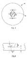
- FIG. 3is a partial sectional view showing a cross-section of the container bottom in FIG. 2 taken at III—III;
- FIG. 4is a partial sectional view of the container bottom in FIG. 3 after opening of a pressure relief vent;
- FIG. 5is a partial sectional view of a reduced thickness groove in a container bottom
- FIG. 6is a partial sectional view showing a cross-section of a portion of a second embodiment of the battery cell of the invention.
- FIG. 7is a plan view showing dimensions of the bottom of the container in FIG. 2 ;
- FIG. 8is a partial sectional view showing dimensions of the reduced thickness groove and container bottom in FIG. 5 .
- a battery cell according to the present inventioncomprises a pressure relief vent mechanism in a metal plate near either or both of the bottom or top of the cell.
- the plate or plates containing the pressure relief vent and the additional space required for the vent to properly openconsume a small amount of the total cell volume, so the internal volume of the cell that may contain the electrochemically active materials can be maximized.
- the pressure relief ventis designed to be reliable, with a small variability in the pressure at which the vent will operate. It is also designed for ease and economy of manufacture.
- FIG. 1An embodiment of a battery cell according to the present invention is shown in FIG. 1 .
- the cell 10 in FIG. 1is a cylindrical alkaline cell, but the invention may be adapted to other cell shapes and electrochemical systems.
- the cell 10has a positive electrode (cathode) 22 , comprising manganese dioxide as the active positive material and an electrically conductive material such as graphite, and a negative electrode (anode) 26 , comprising zinc particles in a gelled aqueous electrolyte solution, in a container 12 .
- An ionically conductive, electrically nonconductive separator 24is disposed between the electrodes.
- the cathode 22is formed in a hollow cylindrical shape against the inner surface of the side wall 18 of the container 12 .
- the inner surface of the cathode 22 and the bottom 14 of the container 12form a cavity, lined with the separator 24 , within which the anode 26 is disposed.
- the cell container 12 in FIG. 1is a metal can with a metal plate forming a closed end (bottom) 14 .
- the metal plate 14may be an integral part of the container 12 , such as in a drawn or extruded can, as shown in FIG. 1 .
- the containermay be a tube, such as an extruded tube or a seamed tube, with a metal plate affixed thereto.
- the open end 16 of the container 12is closed with a closing element 38 .
- the closing element 38comprises at least a seal 32 , which may be in the form of a polymeric gasket or grommet, or a metal plate (not shown) that can cooperate with the container 12 to enclose the internal cell components and keep them sealed inside the cell 10 .
- the closing element 38also comprises a negative contact terminal 30 disposed over the seal 32 .
- the negative contact terminal 30may comprise the metal plate of the closing element 38 .
- the closing element 38may comprise one or more additional components, such as an anode current collector 28 , a separate metal plate disposed between the negative terminal 30 and the seal 32 , and a compression bushing (not shown).
- the compression bushingmay be used to hold the seal 32 in compression against the anode current collector 28 .
- the anode current collector 28may be connected to the negative terminal 30 by a weld 34 , or the negative terminal 30 may be biased against the anode current collector 28 to maintain electrical contact.
- the closing elementmay be supported by an annular bead 36 near the top of the side wall 18 of the container 12 .
- the cell 10 in FIG. 1has a pressure relief vent 40 in the bottom 14 of the container 12 to release gas from the cell 10 in a controlled manner if the internal pressure increases above a predetermined level.
- a pressure relief ventmay be formed in a metal plate in the closing element (e.g., in either a negative terminal or in a separate cover between the negative terminal and the seal), or a pressure relief vent may be formed in both the closed end of the can and in the closing element.
- the inventioncan also be used in combination with a conventional pressure relief vent in the seal, e.g., to provide a redundant vent.
- the cell 10has a positive contact terminal 42 disposed on the bottom 14 of the container 12 , extending over the vent 40 .
- the positive terminal 42may be affixed with welds 54 or by other means that will keep the positive terminal 42 in physical and electrical contact with the bottom 14 of the container 12 .
- the welds 54are positioned on the peripheral flange 48 of the positive terminal 42 , close to the upstanding wall 46 of the nubbin 44 to minimize any constraint by the positive terminal 42 on bulging of the bottom 14 of the container 12 when pressure builds up inside the cell 10 .
- the positive terminal 42has a protruding nubbin 44 .
- the positive terminal 42not only provides an electrical contact surface, but it also provides an attractive, corrosion resistant cover over the bottom 14 of the container 12 and protects the vent 40 from damage.
- the nubbin 44provides an open space into which the vent 40 can open without interference from another cell or an external electrical contact.
- the positive terminal 42also helps to contain internal cell components when the internal pressure is released through the open vent 40 .
- One or more openings 56may also be provided in positive terminal 42 to allow gas to escape.
- the cell 10may be used as a single cell battery or as a component cell in a multiple cell battery.
- a jacket 20When used as a single cell battery, a jacket 20 , sometimes in the form of a heat-shrinkable adhesive label, is disposed around the side wall 18 of the container 12 , with the distal edges of the jacket 20 generally extending over the edges of the container 12 .
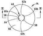
- FIG. 2is a plan view of the outer surface of the bottom 14 of the container 12 of the cell 10 of FIG. 1 .
- the pressure relief vent 40is an interrupted annular ring 58 , in the form of a broken reduced thickness groove, formed in the metal plate 14 comprising the closed bottom end of the cell 10 .
- the unthinned sections 62 a and 62 binterrupt the groove 58 to form two reduced thickness arcs 60 a and 60 b . Adjacent ends of the arcs 60 a and 60 b are separated from each other by unthinned sections 62 a and 62 b .
- Annular ring 58defines an area inside the ring 64 and an area outside the ring 66 .
- the arcs 60 a and 60 bmay be formed in either surface of the metal plate 14 , but forming them in the outer surface provides a smooth surface in contact with internal components of the cell 10 .
- FIG. 3which is a cross section of the container bottom 14 in FIG. 2 taken at III—III, the metal plate 14 has a thickness 68 beyond the reduced thickness arcs 60 a and 60 b .
- the arcs 60 a and 60 beach comprise a groove having a depth 72 , each groove defining a thinned thickness 70 of metal plate 14 at the deepest part of the groove.
- the pressure relief vent 40operates to release gas and/or liquid from inside the cell 10 when the internal pressure of the cell 10 exceeds a predetermined limit.
- the limitis selected such that the vent 40 will open before either the can 12 ruptures elsewhere or the negative terminal 30 or part of the closing element 38 is ejected from the cell 10 .
- the metal plate 14tears or fractures at one or more of the reduced thickness arcs 60 a and 60 b .
- the pressure inside the cell 10is reduced when gas or liquid escapes from the resultant opening(s) in the metal plate 14 .
- the metal plate 14 in FIG. 3is shown after the vent 40 opens in FIG. 4 .
- Portions 74 a and 74 b of the area inside the annular ring 64are deflected generally outward, away from the cell 10 .
- the area inside the ring 64remains attached to the area outside the ring 66 at one or both of the unthinned sections 62 a and 62 b , creating hinges at which the outward deflected portions 74 a and 74 b swing open.
- FIG. 4shows the vent open at both reduced thickness arcs. Generally the vent will open at only one arc—the weaker one. Therefore, the invention can provide redundant vents. If one arc is unable to operate as intended, the vent can open at the other arc to release pressure from the cell.
- the cell 10may have a positive terminal cover extending over the vent 40 . This can provide protection for the vent, insure adequate clearance to the outside of the vent 40 , and provide some containment for material released from inside the cell 10 when the vent 40 opens.
- the space between the metal plate 14 and the inside of the nubbin 44 of the positive terminal 42allows the vent 40 to open outward without the terminal 42 interfering with the outward deflected portions 74 a and 74 b.
- a positive terminal cover 42may not be necessary, as long as there is sufficient clearance on the outside of vent 40 for proper vent operation. In such cells the area inside the annular ring 64 is retained by at least one of the unthinned sections 62 a and 62 b.
- the arcs 60 a and 60 b shown in FIG. 3have a stylized shape with straight vertical walls, a flat horizontal bottom, and a sharp corner between the walls and bottom.
- the side walls and bottomtend not to be straight or flat, and corners within and at the edges of the groove tend to be somewhat rounded.
- the thinned groovesmay have other cross-sectional shapes than that shown in FIG. 3 . For example, they may have a U- or a V-shape, or a trapezoidal shape such as the groove 160 shown in FIG. 5 .
- a pressure relief ventmay be formed, in a similar fashion, in a metal plate in a closing element in the open end of the container.
- Providing a cover, such as the negative terminal cover in FIG. 1 , over the vent-containing metal plate in the closing elementcan provide the same advantages as described above for the positive terminal cover when the vent is in the closed end of the container.
- the ventmust be able to open sufficiently, without interference from the negative terminal cover to relieve internal cell pressure within the desired time.
- a pressure relief vent in the closing elementmay require an additional cell component compared to the cell in FIG. 1 , but in some circumstances forming a vent in a separate metal plate may be easier than forming a vent in a metal plate that is an integral part of the can (e.g., if the can is particularly small in diameter).
- the vent-containing metal plate in the cell shown in FIG. 1is substantially flat.
- the volume taken up by the metal plate and ventcan be greater.
- the metal platemay bulge outward to a greater extent before the vent opens, requiring more clearance to the outside of the vent. Therefore, when the annulus containing the interrupted thinned groove does not protrude from the surface of the metal plate, more space is generally available for active materials.
- the pressure relief venthas two reduced thickness arcs disposed on a single annular ring.
- the ventmay include additional reduced thickness grooves. Additional reduced thickness grooves may be disposed radially inside or outside the annular ring on which the reduced thickness arcs are disposed. They may be straight or curved grooves, intersecting or nonintersecting, though the tooling required to make vents with nonintersecting grooves tends to be simpler, easier to make, and easier to maintain.
- the vent-containing platemay have more than one annular ring, each of which comprises an interrupted reduced thickness groove with a different radius of curvature. Such a vent can be designed to open at different pressures. For instance, the grooves on an inner ring may be designed to open at a relatively low pressure and have a relatively small open area, while those on an outer ring may open at a higher internal pressure to create a larger open area.
- each of the reduced thickness arcshas a single radius of curvature; in other words, the radius of curvature of the radial midpoint of the arc is constant at all points on the arc, and the radii of curvature of the arcs have a common locus (i.e., the radial midpoints of the arcs are all disposed on the same annulus).
- the arcscan be curved arc shapes that do not have single radii of curvature.
- the arc radiican be different from the radius of an annular ring on which the arcs lie; in such embodiments the arcs lie on a broader annulus than that in FIG. 2 .
- Such a vent designmay be particularly useful for another cell shape, such as an oval, rather than a circular, cylindrical shape, so the arc shapes could match the cross-sectional shape of the side wall of the cell container.
- vent designsrequire as little of the total cell volume as practical and not produce ejected parts when the vent opens.
- a simple designis usually better than a more complex design that has no additional advantages.
- Pressure relief vents of the inventioncan be made using any suitable method or combination of methods for producing reduced thickness grooves in metal plates. Suitable methods include, but are not limited to, stamping, casting, forging, rolling, cutting, grinding, laser scribing, and chemical etching. Stamping methods, such as coining, are particularly well suited.
- stamping methodssuch as coining, are particularly well suited.
- the ventWhen the vent is disposed in the bottom of a can, the can may be made by deep drawing or impact extrusion, and the vent may be formed in the can bottom, either as a separate process or as part of the can manufacturing process using either transfer or progressive die technology. In an example of a combined process, cans are deep drawn on a press using a progressive die. A strip of metal is fed into the die and is indexed through a series of punches and dies.
- Each punch and diedraws the can deeper and/or forms the can closer to its final shape.
- One or more of the punch and diesets coins the reduced thickness grooves into the bottom of the can. This is generally done near the end of the process.
- the formed canscomplete with pressure relief vents in their bottoms, are punched out of the strip of metal.
- the thickness of the can side wall and bottomcan be controlled by a combination of selection of the characteristics and thickness of the metal strip and the amount and location of metal stretching (and thinning) during drawing (a result of the die design).
- One or more separate stepscan also be used to flatten or otherwise shape the can bottom after forming the reduced thickness grooves, since coining the grooves tends to distort the can bottom shape.
- the reduced thickness grooves of the pressure relief ventcan be formed by coining, either during the can/metal plate manufacturing process, or as a separate process.
- coiningforce is applied to the metal, located between a punch and a die.
- Either or both of the punch and diecan include projections, which cause the metal to flow into the desired shape.
- a pressure relief ventIn designing a pressure relief vent, it is desirable to take into account manufacturing considerations, such as cost and ease of die design and fabrication, operating speeds of equipment, stresses on forming equipment, wear and maintenance of tooling (e.g., punches and dies), variability in manufactured articles, and tolerances of specified dimensions. It may be desirable to make compromises when some manufacturing considerations are in conflict with others.
- radially symmetrical vent designscontribute to minimizing stresses on the tooling. This tends to reduce the required frequency of maintenance of the tooling, the frequency of tooling replacement, and the variability in vent dimensions, thereby making a positive contribution to product cost, quality, and reliability. It is desirable, to the extent practical, to incorporate into the vent design shapes for which tooling is easy to fabricate, wear resistant, and easy to maintain. Therefore, simplicity of the vent design is generally desirable.
- the pressure relief vent designmust be able to operate effectively to release excessive pressure from the cell in a controlled, safe manner.
- a good vent designwill open at the desired pressure differential between the inside and outside of the cell and do so quickly enough and with a sufficiently large open area. Desirable characteristics can also include a minimum vent activation pressure that is well beyond the normal operating pressure of the cell, a maximum vent activation pressure that is well below the pressure at which an uncontrolled release would occur, and low variability in vent activation pressure. It can also be advantageous for the vent to open fully, to create the maximum opening area, in a very short time. It may also be desirable for the vent to operate in such a way as to minimize cell distortion (e.g., bulging of the can) before, during, and after opening.
- vent activation pressureand the way in which the vent opens.
- metal type and characteristicse.g., hardness, tensile stress, and elongation
- unthinned thickness of the vent-containing platethickness of the vent-containing plate in the thinned grooves
- thickness of the vent-containing plate in the thinned groovescross-sectional shapes of the grooves
- diameter of the vent-containing plateplanar shapes and dimensions of the grooves
- locations of the grooves on the vent-containing plateand widths of the unthinned sections interrupting the groove arcs.
- Computer modeling software using finite element analysiscan be a useful tool for designing pressure relief vents; it can take such factors into account.
- the can material and thicknessmay be selected based on other requirements, such as the cell electrochemistry, size, and method of closing and sealing. Those same factors are also important in determining the desired pressure at which the pressure relief vent should open.
- Finite element analysiscan then be used to predict the vent activation pressure for a given vent design and to refine the design to meet the needs of a particular cell.
- the embodiment of the electrochemical battery cell of the invention shown in FIG. 1is a cylindrical alkaline Zn/MnO 2 cell with a container comprising a metal can with a closed bottom end and an open top end.
- a closing elementis disposed in the open end of the can to seal the active materials and electrolyte in the cell. This embodiment is described in further detail below.
- the canmay be made of any suitable metal.
- a suitable metalis one that can be formed into the desired shape and can be adapted to seal the contents within the cell. It will be sufficiently stable, in contact with both the internal components of the cell and the intended external environment, to provide acceptable performance, even after storage for long periods of time. Since it also functions as the cathode current collector, the can will have good electrical conductivity.
- Steelis typically used for alkaline Zn/MnO 2 cells.
- the external surface of the steel containermay be plated to provide corrosion resistance, high electrical conductivity, and an attractive appearance.
- the internal surface of at least that portion of the side wall in contact with the cathodemay be coated with a material, such as graphite, to provide good electrical contact between the can and the cathode.
- a suitable material for alkaline Zn/MnO 2 cell cansis a low carbon, aluminum killed, SAE 1006 or equivalent steel substrate comprising maximums of 0.08 weight percent carbon, 0.45 weight percent manganese, 0.025 weight percent phosphorous and 0.02 weight percent sulfur.
- the grain size of the steelis ASTM 8 to 12.
- the steel stripmay have the following mechanical properties: 45,000 pound maximum yield strength; 60,000 pound ultimate strength; 25 percent minimum elongation in 2 inches (50.8 mm); and 82 maximum Rockwell 15T hardness.
- the can side walls and bottomare typically from about 0.005 inch (0.13 mm) to about 0.014 inch (0.36 mm) thick, usually no more than about 0.010 inch (0.25 mm). At less than 0.005 inch (0.13 mm), the can sides and/or bottom can bulge too much at acceptable internal cell pressures. This can cause problems getting batteries into and out of battery compartments. If the can is more than 0.014 inch (0.36 mm) thick, the volume of the cell available for active materials may be unnecessarily reduced.
- the can walls and bottommay be the same thickness or different thicknesses.
- the can side wallcan have different thicknesses in different areas to achieve the strength where needed but minimize the amount and volume of material elsewhere.
- the cathodeis formed in the shape of a hollow circular cylinder against the inner surface of the can side wall.
- a common alkaline Zn/MnO 2 cell cathodecomprises a mixture of MnO 2 active material and particles of graphite, which is used to increase the electrical conductivity of the electrode.
- the MnO 2is often an electrolytic manganese dioxide (EMD).
- EMDelectrolytic manganese dioxide
- Suitable alkaline cell grade EMDcan be obtained from Kerr-McGee Chemical Corp. (Oklahoma City, Okla., USA) and Erachem Comilog, Inc. (Baltimore, Md., USA).
- the EMDis a high-potential EMD (pH-voltage of at least 0.86 volt) with a potassium content less than 200 ppm, as disclosed in International Patent Publication No. WO 01/11703 A1, published 15 Feb. 2001.
- the graphitemay be an alkaline grade graphite powder, an expanded graphite, or a mixture thereof.
- a suitable expanded graphite, according to International Patent Publication No. WO 99/00270, published 6 Jan. 1999,is available from Superior Graphite Co. (Chicago, Ill., USA).
- the mixturetypically also comprises water (with or without electrolyte salt), and may also include small (typically less than 2 percent by weight) amounts of other materials, generally to improve performance in some way. Examples of such performance-enhancing materials include niobium-doped TiO 2 , as disclosed in International Patent Application No. WO 00/79622 A1, and barium sulfate.
- a binderis added to the cathode mixture to strengthen the cathode.
- the bindermay also have some additional desirable properties.
- the bindermay function as a lubricant when the cathode is formed or may retain electrolyte in the cell, facilitating ion mobility during discharge.
- a minimal amount of binder(or none) is used in order to maximize the amounts of active and electrically conductive materials.
- a binderWhen a binder is used it generally comprises about 0.1 to 6, more typically 0.2 to 2, weight percent of the solid components of the positive electrode mixture.
- Suitable binders for alkaline Zn/MnO 2 cathodesinclude monomers and polymers of materials such as acrylic acid, acrylic acid salts, tetrafluoroethylene, calcium stearate, acrylic acid/sodium sulfonate copolymer, and copolymers of styrene and one or more of butadiene, isoprene, ethylene butylene, and ethylene propylene. Binder materials may be used alone or in combination.
- CARBOPOL® 940an acrylic acid in the 100% acid form from B. F.
- Coathylene HA 1681(a polyethylene from Hoechst Celanese), KRATON® G1702 (a diblock copolymer of styrene, ethylene, and propylene from Kraton Polymers Business), poly (acrylic acid-co-sodium 4-styrene sulfonate) have been found to provide good electrode strength.
- Mixed binderssuch as a mixture of CARBOPOL® 940 and either TEFLON® T30B or TEFLON® 6C (tetrafluoroethylenes from E. I. du Pont de Nemours & Co.), can be advantageous.
- a CARBOPOL® to TEFLON® weight ratio of from 1:4 to 4:1can be advantageous.
- the higher the ratiothe stronger the cathode.
- the cathodeis stronger with a CARBOPOL® to TEFLON® weight ratio of 3:1 than with a ratio of 1:1 or 1:3.
- the binder level in the cathodemay be about 0.2 to 2, preferably 0.2 to 1, weight percent, based on the solid, undissolved components in the cathode mixture.
- the amount of water in the mixtureis generally from about 1.5 to 8.0 percent, based on the weight of the solid, undissolved ingredients in the cathode prior to molding.
- a typical range for use in making impact molded cathodesis 6 to 8 percent.
- a typical range for use in ring moldingis 1.5 to 6 percent.
- ring moldingTwo common methods of forming alkaline cell cathodes are ring molding and impact molding.
- ring moldingone or more (usually 3 to 5) rings are formed and then inserted into the can in a stack (one ring on top of another). Good physical and electrical contact between the can and the cathode are desirable.
- the outside diameter of the ringsmay be made slightly larger than the inside diameter of the can to produce an interference fit, or the rings may be slightly smaller than the can to facilitate insertion, after which the rings are reformed slightly by applying force to the inside and/or top surface, thereby forcing cathode mixture firmly against the can.
- impact moldingthe desired quantity of cathode mixture is put into the bottom of the can and molded to the desired dimensions using a ram that is inserted into the center of the can.
- the percent solids packing of the molded cathode mixtureis typically about 70 to 79 percent, with 72 percent being most typical in impact molded cathodes and 75–79 percent being most typical in ring molded cathodes.
- a separatoris inserted into the cavity formed in the cathode to separate the anode from both the cathode and the can bottom.
- the separatoris typically one or two layers of a porous, wet-laid material of nonwoven synthetic fibers, such as 0.004 inch (0.10 mm) thick VLZ 105 grade separator from Nippon Kodoshi Corp. of Kochi-ken, Japan or 0.003 inch (0.08 mm) thick grade FS2100/063 separator from Freudenberg Vliesstoffe KG of Neuenburg, Germany.
- Each layer of separatorcan be folded and preformed into an elongated basket shape from a long strip of separator material.
- the separatorcovers the entire inside surface of the molded cathode and any exposed inside surface of the can bottom and extends upward beyond the top of the molded cathode, often high enough to contact the inside surface of the closing element when the cell is completed.
- the anode mixtureis typically a flowable gel that is dispensed into the cavity in the cathode and separator.
- the gelcomprises a mixture of gelled zinc particles.
- the zincmay be in powder or flake form, or a combination of the two.
- An unamalgamated zinc alloycomprising bismuth, indium, and aluminum may be used.
- Zinc powderpreferably having a d 50 of about 110 ⁇ m, may be obtained from Umicore (Brussels, Belgium), and zinc flake (e.g., grade 5454.3) may be obtained from Transmet Corp. (Columbus, Ohio, USA).
- the anodealso comprises water, potassium hydroxide electrolyte, and a gelling agent.
- Acrylic acid in the 100% acid formsuch as CARBOPOL® 940 from B. F. Goodrich Specialty Chemicals (Cleveland, Ohio, USA) is a common gelling agent. Small amounts of other materials may also be added to the anode mixture and/or electrolyte to minimize gas generation in the cell and/or enhance discharge performance. Examples of such materials include In(OH) 3 , ZnO, and sodium silicate.
- the total KOH concentration in the electrolyte in the completed cellincluding the anode, the cathode, and any additional electrolyte or water added to the cell, will generally be from about 36 to about 40 weight percent.
- the relative amounts of cathode and anode in the cellare balanced so that if the cell were completely discharged there would be a small amount of one of the anode and cathode remaining. A slight excess of anode is often desirable.
- the nominal ratio of anode to cathodebased on theoretical input capacities of each (assuming a 1.33 electron discharge of the MnO 2 ) may be between 0.90:1 and 0.99:1.
- the closing elementcan include an anode current collector.
- the current collectorextends through an opening in the seal to make contact with the negative terminal cover.
- the anode collectorcan be in the form of a nail or pin.
- the collectorcan be made of brass, coated with a high hydrogen overvoltage material, such as indium or tin. Indium may be applied to the collector by burnishing, as disclosed in U.S. Pat. No. 5,188,869. Alternatively, tin may be applied by plating.
- the cell in FIG. 1has a pressure relief vent formed in the can bottom to allow the use of a low volume closing element that does not include a pressure relief vent.
- the pressure relief vent of the inventionis a low volume vent, it can be formed in a metal plate that is part of a low volume closing element.
- the closing element in FIG. 1has a metal cover, which also serves as the negative contact terminal of the cell, and an annular gasket between the cover and the can.
- the coveris electrically conductive and can be made of a metal, such as steel.
- the coveris often plated with nickel on the outer surface to make it corrosion resistant.
- the covercan also be coated on the inside surface to prevent gas-producing reactions if electrolyte and/or electrode materials come in contact with it.
- the gasketcan be an elastomeric material capable of creating a compressive seal between the can and the cover.
- Suitable gasket materialsinclude nylon, polyethylene, polypropylene, polytetrafluoroethylene, blends of polymers (e.g., polypropylene and an impact modified poly(phenylene oxide) such as NORYL® EXTENDTM PPX7110 and PPX7125, from General Electric Co. of Pittsfield, Mass., USA), and other polymeric materials with relatively low cold-flow rates under compression.
- a sealantmay also be used at the interface between the gasket and can or between the gasket and cover.
- the can side wallhas an annular bead just below the gasket to support the closing member.
- FIG. 6An example of a cell 110 in which the cover is crimped over the outside of the open top of the can is shown in FIG. 6 .
- the top edge of the can 112is curled outward for strength.
- the open end of the can, beneath the curled edge,is necked inward so the cover 130 does not extend radially outward farther than the outside diameter of the main body of the can.
- the anode current collector 128is electrically connected to the center of the cover.
- the peripheral edge of the coveris crimped inward against the gasket so the cover is locked in place under the curled edge of the can.
- the gasket 132not only forms a compressive seal between the cover and can, but it extends across the inside surface of the cover and forms a compressive seal around the current collector, protecting the cover from the cell contents.
- This designis low in volume and has the additional advantage that little or no axial loading is placed on the can during cell closing. This can eliminate the need for a bead in the can to support the closing member and make the use of a can with a thinner side wall possible.
- Other low volume designsmay be used in cells of the invention. Examples include the designs disclosed in U.S. Pat. Nos.
- Cans suitable for use in LR6 type cellswere made with pressure relief vents in their bottom ends as follows.
- Canswere deep drawn from an aluminum-killed, low carbon steel strip (carbon content of approximately 0.04%) having a nominal thickness of 0.010 inch (0.254 mm), a Vickers microhardness of approximately 120, and a grain size of ASTM 8 to 12.
- the stripwas plated with nickel on the outside surface and nickel and cobalt on the inside surface and was diffusion annealed.
- the canswere manufactured on a U.S. Baird multiple transfer press.
- a stamping die incorporating replaceable carbide insertswas used to fabricate the vent.
- a single coining stepwas used to form the reduced thickness grooves of pressure relief vents into the outside surfaces of the can bottoms.
- the raised portions of the carbide inserts that physically impact against can bottoms to form the grooveswere polished to a surface finish of 2 microinches (0.051 ⁇ m) or less using a diamond paste polishing compound. This was followed by a can bottom flattening step, to insure a flat bottom.
- a water-based lubricantwas used to cool and lubricate the steel and die during forming. The finished cans were cleaned by an alkaline cleaning solution to remove lubricant and other residue.
- Nominal dimensions of the desired LR6 canswere those shown in Table 1.
- the pressure relief vent design selectedis shown in detail in FIGS. 7 and 8 .
- Each of the reduced thickness arcshas a single radius of curvature equal to the radius of curvature of the annular ring.
- the maximum internal pressure at which the pressure relief vent would open in completed cells, including terminal covers and jackets,was set at 1650 pounds per square inch (psi) (116.0 kg/cm 2 ).
- the minimum cell vent pressurewas set at 1050 psi (73.8 kg/cm 2 ). These limits for individual LR6 cells corresponded to can vent pressures of 800 to 1400 psi (56.2 to 98.4 kg/cm 2 ).
- the desired nominal dimensions of the pressure relief ventwere selected to be those in Table 2 to produce a can with an average vent pressure between 1000 and 1150 psi (between 70.3 and 80.8 kg/cm 2 ).
- the shape of the groovewas selected to facilitate manufacturing. Tooling was easily maintained with the wall angle and the width at the bottom of the groove shown. The tooling was initially set for a groove thickness of approximately 0.003 inch (0.076 mm) and then adjusted until the desired average vent pressure was obtained. Adjusting the groove thickness can also be a convenient means of maintaining the desired vent pressure during the manufacturing process. It may be desirable to set a minimum groove thickness limit; 0.002 inch (0.051 mm) was selected as the minimum thickness in this example.
- the width of the unthinned sections between the ends of the reduced thickness arcswas selected to be 0.060 inch (1.52 mm) to insure that the area of the can bottom within the annular ring would remain attached to the area radially outside the annular ring when the vent opened.
- FIG. 7 & 8Ref. Description Dimension R Radius of curvature of annular ring 0.100 in. (from longitudinal axis of can to (2.54 mm) radial midpoint of ring) W Width of unthinned section between reduced 0.060 in. thickness arcs (between radial midpoints (1.52 mm) of arcs) D Depth of groove 0.007 in. (0.18 mm) T Groove thickness 0.003 in. (0.076 mm) G Width of groove at bottom 0.004 in. (0.10 mm) A Angle of groove wall (from vertical) 30 deg. L Arc length of reduce thickness arc (each arc) 145 deg.
- FIGS. 7 and 8are stylized drawings, showing grooves with regular, flat surfaces and sharp angles. Actual formed pressure relief vents will have grooves with surfaces that are somewhat irregular. In measuring dimensions on actual formed vents, averaging can be used to compensate for irregularities. Potting and cross sectioning can be used to prepare cans for measurement of the pressure relief vent dimensions. Other methods can also be used to produce comparable results. Nondestructive measurements of the groove depth can be made using an instrument such as a SmartScope Model ZIP 250 (Optical Gaging Products, Inc., Rochester, N.Y., USA). The thickness of the can at the bottom of the groove (groove thickness) can be calculated by subtracting this groove depth measurement from the unthinned bottom thickness, which can be measured with a micrometer gauge.
- Cans from Example 1were tested to evaluate the pressure at which the pressure relief vents would open. Because cans are more easily tested when they are empty than after they have been used in cells, a correlation was first established between the results of cell and can vent pressure. Live cells were tested hydraulically for both convenience and to closely approximate the way in which pressure builds up in cells. Empty cans were tested using a pneumatic tester as a matter of convenience.
- Pneumatic testing of empty canswas done using a Fastest Pneumatic Can Vent Tester, Model FES0-04, available from Fastest Corporation, St. Paul, Minn., USA. Each can was tested by placing it into a test fixture, sealing the open end of the can against the fixture, and pressurizing the inside of the can at a selected rate of about 50 lbs./sec. (3.5 kg/sec.) until the pressure relief vent opened. The rate of pressurization was controlled by adjusting a needle valve on the pressure inlet so that the time interval between pressure readings of 300 and 800 psi (21.1 and 56.2 kg/cm 2 ) was 10 seconds. The pressure within the can was monitored with an electronic gauge meter with a peak hold feature.
- the vent pressure of a canwas the peak pressure reading from this gauge after the vent had opened. The can was also observed to determine if the area inside the vent remained connected to the area outside the vent, and if so, whether at one or both of the unthinned sections between the reduced thickness arcs of the vent.
- the test fixturewas designed specifically for this testing. The test fixture design can affect the test results, so the correlation between cell and can vent pressures will depend on the test fixtures used.
- Cans suitable for use in LR03 type cellswere made with the nominal dimensions shown in Table 3.
- the can manufacturing processwas as described in Example 1, using 0.010 inch (0.25 mm) thick steel strip.
- the selected pressure relief vent designwas that shown in FIGS. 7 and 8 , with the nominal dimensions shown in Table 4.
- the shape of the groove (depth, wall angle, and width at the bottom) and the width of the unthinned sections between the ends of the arcswere kept the same as in Example 1.
- the radius of curvature of the annular ringwas reduced to produce a desired nominal can vent pressure of 1800 psi (126.5 kg/cm 2 ).
- FIGS. 7 & 8Ref. Description Dimension R Radius of curvature of annular ring (from 0.070 in. longitudinal axis of can to radial midpoint (1.78 mm) of ring) W Width of unthinned section between reduced 0.060 in. thickness arcs (between radial midpoints (1.52 mm) of arcs) D Depth of groove 0.007 in. (0.18 mm) T Groove thickness 0.003 in. (0.076 mm) G Width of groove at bottom 0.004 in. (0.10 mm) A Angle of groove wall (from vertical) 30 deg. L Arc length of reduce thickness arc (each arc) 160 deg.
- Vent pressures of cans from Example 3were determined in the same manner as in Example 2. The actual can vent pressure averaged 1848 psi (129.9 kg/cm 2 ), with a standard deviation of 79 psi (5.6 kg/cm 2 ).
- a pressure relief ventwas designed according to FIG. 7 for LR6 cell cans made from 0.008 inch (0.20 mm) thick steel strip.
- the nominal can dimensionsare shown in Table 5, and the nominal vent dimensions are shown in Table 6. Because the cans were made for use in cells with a different closing element design than the cans in Example 1, the outside diameter of the top portion of the can is different. Reducing the can bottom thickness from 0.010 inch (0.25 mm), as in Example 1, also reduced the can vent pressure, because the required vent pressure will also be lower, so the same vent dimensions as used in Example 1 could be used in Example 5.
- FIGS. 7 & 8Ref. Description Dimension R Radius of curvature of annular ring (from 0.100 in. longitudinal axis of can to radial midpoint (2.54 mm) of ring) W Width of unthinned section between reduced 0.060 in. thickness arcs (between radial midpoints (1.52 mm) of arcs) D Depth of groove 0.007 in. (0.18 mm) T Groove thickness 0.003 in. (0.076 mm) G Width of groove at bottom 0.004 in. (0.10 mm) A Angle of groove wall (from vertical) 30 deg. L Arc length of reduce thickness arc (each arc) 145 deg.
- Cans from Example 5were vent tested as in Example 2.
- the vent pressuresaveraged 865 psi (60.8 kg/cm 2 ), with a standard deviation of 31.3 psi (2.2 kg/cm 2 ).
- no ejection of any portion of the can bottomoccurred; the section of the can bottom inside the annular ring remained attached to the can in all cases.
- a pressure relief ventwas designed for cans to be used in a LR20 type cell. Nominal can dimensions are shown in Table 7, and nominal pressure relief vent dimensions are shown in Table 8.
- the shape of the groove (depth, wall angle, and width at the bottom) and the width of the unthinned sections between the ends of the arcswere kept the same as in Example 1.
- the radius of curvature of the annular ringwas increased to produce a desired nominal can vent pressure of 475 psi (33.4 kg/cm 2 ).
- the selected pressure relief vent designwas that shown in FIG. 7 , with the nominal dimensions shown in Table 8.
- FIGS. 7 & 8Ref. Description Dimension
- RRadius of curvature of annular ring (from 0.1745 in. longitudinal axis of can to radial midpoint (4.43 mm) of ring)
- WWidth of unthinned section between reduced 0.060 in. thickness arcs (between radial midpoints (1.52 mm) of arcs)
- DDepth of groove 0.007 in. (0.18 mm)
- a Angle of groove wall(from vertical) 30 deg.
- LArc length of reduce thickness arc (each arc) 160 deg.
- vent pressureswere not exactly at the preselected nominal values in Examples 2, 4, and 6, they were within about 10%, showing that finite element analysis is a useful tool for pressure relief vent design. If necessary, adjustments to the actual average vent pressures can be made by changing the radius of curvature of the reduced thickness grooves. Alternatively, vent pressures can be adjusted by changing one or more other vent design parameters, such as the width of the unthinned section between the ends of the reduced thickness arcs, the width at the bottom of the groove, and the groove thickness.
- the inventionis useful in cells of various sizes, such as cells with container outside diameters from about 0.4 inch (10 mm) to about 1.4 inch (36 mm), and with pressure relief vents having an interrupted annular ring (groove) radius of curvature about 0.06 inch (1.5 mm) to about 0.18 inch (4.6 mm).
- an annular ring radius of curvature of 0.100 inch (2.54 mm)has been demonstrated, but other radii of curvature, e.g., from about 0.085 inch (2.16 mm) to about 0.115 inch (2.92 mm), and beyond, can be expected to be suitable, by adjusting other vent design dimensions.
Landscapes
- Chemical & Material Sciences (AREA)
- Chemical Kinetics & Catalysis (AREA)
- Electrochemistry (AREA)
- General Chemical & Material Sciences (AREA)
- Engineering & Computer Science (AREA)
- Manufacturing & Machinery (AREA)
- Sealing Battery Cases Or Jackets (AREA)
- Gas Exhaust Devices For Batteries (AREA)
Abstract
Description
| TABLE 1 | |||
| Description | Dimension | ||
| Can height | 1.926 in. | ||
| (48.92 mm) | |||
| Height to top of can step | 1.807 in. | ||
| (from bottom outside) | (45.90 mm) | ||
| Outside diameter of can | 0.568 in. | ||
| (above can step) | (14.43 mm) | ||
| Inside diameter of can body | 0.526 in. | ||
| (below can step) | (13.36 mm) | ||
| Can bottom corner radius of | 0.025 in. | ||
| curvature (outside surface) | (0.64 mm) | ||
| Can side wall thickness | 0.0103 in. | ||
| above step | (0.26 mm) | ||
| Can side wall thickness | 0.0098 in. | ||
| below step | (0.25 mm) | ||
| Can bottom thickness | 0.010 in. | ||
| (unthinned) | (0.25 mm) | ||
| TABLE 2 | ||
| FIG. 7 & 8 | ||
| Ref. | Description | Dimension |
| R | Radius of curvature of annular ring | 0.100 in. |
| (from longitudinal axis of can to | (2.54 mm) | |
| radial midpoint of ring) | ||
| W | Width of unthinned section between reduced | 0.060 in. |
| thickness arcs (between radial midpoints | (1.52 mm) | |
| of arcs) | ||
| D | Depth of groove | 0.007 in. |
| (0.18 mm) | ||
| T | Groove thickness | 0.003 in. |
| (0.076 mm) | ||
| G | Width of groove at bottom | 0.004 in. |
| (0.10 mm) | ||
| A | Angle of groove wall (from vertical) | 30 deg. |
| L | Arc length of reduce thickness arc (each arc) | 145 deg. |
| TABLE 3 | |||
| Description | Dimension | ||
| Can height | 1.689 in. | ||
| (42.90 mm) | |||
| Height to top of can step | 1.569 in. | ||
| (from bottom outside) | (39.86 mm) | ||
| Outside diameter of can | 0.4115 in. | ||
| (above can step) | (10.45 mm) | ||
| Inside diameter of can body | 0.380 in. | ||
| (below can step) | (9.66 mm) | ||
| Can bottom corner radius of | 0.020 in. | ||
| curvature (outside surface) | (0.51 mm) | ||
| Can side wall thickness | 0.010 in. | ||
| above step | (0.25 mm) | ||
| Can side wall thickness | 0.008 in. | ||
| below step | (0.21 mm) | ||
| Can bottom thickness | 0.0090–0.0105 in. | ||
| (unthinned) | (0.23–0.27 mm) | ||
| TABLE 4 | ||
| FIGS. 7 & 8 | ||
| Ref. | Description | Dimension |
| R | Radius of curvature of annular ring (from | 0.070 in. |
| longitudinal axis of can to radial midpoint | (1.78 mm) | |
| of ring) | ||
| W | Width of unthinned section between reduced | 0.060 in. |
| thickness arcs (between radial midpoints | (1.52 mm) | |
| of arcs) | ||
| D | Depth of groove | 0.007 in. |
| (0.18 mm) | ||
| T | Groove thickness | 0.003 in. |
| (0.076 mm) | ||
| G | Width of groove at bottom | 0.004 in. |
| (0.10 mm) | ||
| A | Angle of groove wall (from vertical) | 30 deg. |
| L | Arc length of reduce thickness arc (each arc) | 160 deg. |
| TABLE 5 | |||
| Description | Dimension | ||
| Can height | 1.924 in. | ||
| (48.86 mm) | |||
| Height to top of can step | 1.766 in. | ||
| (from bottom outside) | (44.86 mm) | ||
| Outside diameter of can | 0.582 in. | ||
| (above can step) | (14.78 mm) | ||
| Inside diameter of can body | 0.530 in. | ||
| (below can step) | (13.46 mm) | ||
| Can bottom corner radius of | 0.025 in. | ||
| curvature (outside surface) | (0.64 mm) | ||
| Can side wall thickness | 0.008 in. | ||
| above step | (0.20 mm) | ||
| Can side wall thickness | 0.008 in. | ||
| below step | (0.20 mm) | ||
| Can bottom thickness | 0.007–0.009 in. | ||
| (unthinned) | (0.18–0.23 mm) | ||
| TABLE 6 | ||
| FIGS. 7 & 8 | ||
| Ref. | Description | Dimension |
| R | Radius of curvature of annular ring (from | 0.100 in. |
| longitudinal axis of can to radial midpoint | (2.54 mm) | |
| of ring) | ||
| W | Width of unthinned section between reduced | 0.060 in. |
| thickness arcs (between radial midpoints | (1.52 mm) | |
| of arcs) | ||
| D | Depth of groove | 0.007 in. |
| (0.18 mm) | ||
| T | Groove thickness | 0.003 in. |
| (0.076 mm) | ||
| G | Width of groove at bottom | 0.004 in. |
| (0.10 mm) | ||
| A | Angle of groove wall (from vertical) | 30 deg. |
| L | Arc length of reduce thickness arc (each arc) | 145 deg. |
| TABLE 7 | |||
| Description | Dimension | ||
| Can height | 2.346 in. | ||
| (59.59 mm) | |||
| Height to midpoint of can | 2.088 in. | ||
| step (from bottom outside) | (53.04 mm) | ||
| Outside diameter of can | 1.319 in. | ||
| (above can step) | (33.50 mm) | ||
| Inside diameter of can body | 1.277 in. | ||
| (below can step) | (32.44 mm) | ||
| Can bottom corner radius of | 0.038 in. | ||
| curvature (outside surface) | (0.97 mm) | ||
| Can side wall thickness | 0.0110–0.0125 in. | ||
| above step | (0.28–0.32 mm) | ||
| Can side wall thickness | 0.0090–0.0110 in. | ||
| below step | (0.23–0.28 mm) | ||
| Can bottom thickness | 0.0095–0.0105 in. | ||
| (unthinned) | (0.24–0.27 mm) | ||
| TABLE 8 | ||
| FIGS. 7 & 8 | ||
| Ref. | Description | Dimension |
| R | Radius of curvature of annular ring (from | 0.1745 in. |
| longitudinal axis of can to radial midpoint | (4.43 mm) | |
| of ring) | ||
| W | Width of unthinned section between reduced | 0.060 in. |
| thickness arcs (between radial midpoints | (1.52 mm) | |
| of arcs) | ||
| D | Depth of groove | 0.007 in. |
| (0.18 mm) | ||
| T | Groove thickness | 0.003 in. |
| (0.076 mm) | ||
| G | Width of groove at bottom | 0.004 in. |
| (0.10 mm) | ||
| A | Angle of groove wall (from vertical) | 30 deg. |
| L | Arc length of reduce thickness arc (each arc) | 160 deg. |
Claims (35)
Priority Applications (14)
| Application Number | Priority Date | Filing Date | Title |
|---|---|---|---|
| US10/365,197US7195839B2 (en) | 2003-02-11 | 2003-02-11 | Battery cell with improved pressure relief vent |
| US10/439,096US6861174B2 (en) | 2003-02-11 | 2003-05-15 | Electrochemical cell with low volume cover assembly |
| CNB2004800037231ACN100359715C (en) | 2003-02-11 | 2004-02-09 | Electrochemical cell with low volume cap assembly |
| EP04709479.2AEP1595299B1 (en) | 2003-02-11 | 2004-02-09 | Battery cell with improved pressure relief vent |
| DE602004029233TDE602004029233D1 (en) | 2003-02-11 | 2004-02-09 | ELECTROCHEMICAL CELL WITH LOW VOLUME COVER ASSEMBLY |
| PCT/US2004/003743WO2004073093A2 (en) | 2003-02-11 | 2004-02-09 | Electrochemical cell with low volume cover assembly |
| JP2006503431AJP4829776B2 (en) | 2003-02-11 | 2004-02-09 | Battery cell with improved pressure relief |
| PCT/US2004/003742WO2004073092A2 (en) | 2003-02-11 | 2004-02-09 | Battery cell with improved pressure relief vent |
| EP04709454AEP1595298B1 (en) | 2003-02-11 | 2004-02-09 | Electrochemical cell with low volume cover assembly |
| CNB2004800037246ACN100382357C (en) | 2003-02-11 | 2004-02-09 | Battery cell with improved pressure relief vent |
| HK06104483.0AHK1084241B (en) | 2003-02-11 | 2004-02-09 | Electrochemical cell with low volume cover assembly |
| AT04709454TATE482479T1 (en) | 2003-02-11 | 2004-02-09 | ELECTROCHEMICAL CELL WITH LOW VOLUME COVER ASSEMBLY |
| JP2006503432AJP5224573B2 (en) | 2003-02-11 | 2004-02-09 | Electrochemical cell with small volume cover assembly |
| US11/700,638US8076015B2 (en) | 2003-02-11 | 2007-01-31 | Battery cell with improved pressure relief vent |
Applications Claiming Priority (1)
| Application Number | Priority Date | Filing Date | Title |
|---|---|---|---|
| US10/365,197US7195839B2 (en) | 2003-02-11 | 2003-02-11 | Battery cell with improved pressure relief vent |
Related Child Applications (2)
| Application Number | Title | Priority Date | Filing Date |
|---|---|---|---|
| US10/439,096Continuation-In-PartUS6861174B2 (en) | 2003-02-11 | 2003-05-15 | Electrochemical cell with low volume cover assembly |
| US11/700,638ContinuationUS8076015B2 (en) | 2003-02-11 | 2007-01-31 | Battery cell with improved pressure relief vent |
Publications (2)
| Publication Number | Publication Date |
|---|---|
| US20040157115A1 US20040157115A1 (en) | 2004-08-12 |
| US7195839B2true US7195839B2 (en) | 2007-03-27 |
Family
ID=32824584
Family Applications (3)
| Application Number | Title | Priority Date | Filing Date |
|---|---|---|---|
| US10/365,197Expired - LifetimeUS7195839B2 (en) | 2003-02-11 | 2003-02-11 | Battery cell with improved pressure relief vent |
| US10/439,096Expired - LifetimeUS6861174B2 (en) | 2003-02-11 | 2003-05-15 | Electrochemical cell with low volume cover assembly |
| US11/700,638Expired - Fee RelatedUS8076015B2 (en) | 2003-02-11 | 2007-01-31 | Battery cell with improved pressure relief vent |
Family Applications After (2)
| Application Number | Title | Priority Date | Filing Date |
|---|---|---|---|
| US10/439,096Expired - LifetimeUS6861174B2 (en) | 2003-02-11 | 2003-05-15 | Electrochemical cell with low volume cover assembly |
| US11/700,638Expired - Fee RelatedUS8076015B2 (en) | 2003-02-11 | 2007-01-31 | Battery cell with improved pressure relief vent |
Country Status (7)
| Country | Link |
|---|---|
| US (3) | US7195839B2 (en) |
| EP (1) | EP1595299B1 (en) |
| JP (1) | JP4829776B2 (en) |
| CN (2) | CN100382357C (en) |
| AT (1) | ATE482479T1 (en) |
| DE (1) | DE602004029233D1 (en) |
| WO (1) | WO2004073092A2 (en) |
Cited By (4)
| Publication number | Priority date | Publication date | Assignee | Title |
|---|---|---|---|---|
| US20080026286A1 (en)* | 2006-07-31 | 2008-01-31 | Eveready Battery Company, Inc. | Nail-type current collector with non-conductive core and surface metallization for electrochemical cell |
| WO2010120906A3 (en)* | 2009-04-15 | 2011-01-13 | Johnson Controls - Saft Advanced Power Solutions Llc | Vent for electrochemical cell |
| US20110091749A1 (en)* | 2009-10-15 | 2011-04-21 | Ac Propulsion, Inc. | Battery Pack |
| US20140233156A1 (en)* | 2012-06-28 | 2014-08-21 | Nichicon Corporation | Pressure valve for electrolytic capacitor, and electrolytic capacitor using same |
Families Citing this family (63)
| Publication number | Priority date | Publication date | Assignee | Title |
|---|---|---|---|---|
| CN101577347B (en)* | 2003-08-18 | 2012-05-30 | 鲍尔热尼系统公司 | Method for manufacturing nickel zinc batteries |
| US20080163478A1 (en)* | 2003-08-18 | 2008-07-10 | Powergenix Systems, Inc. | Method for manufacturing nickel zinc batteries |
| KR100700564B1 (en)* | 2004-11-10 | 2007-03-28 | 엘지전자 주식회사 | Battery and mobile terminal with same |
| US8703330B2 (en)* | 2005-04-26 | 2014-04-22 | Powergenix Systems, Inc. | Nickel zinc battery design |
| KR100686827B1 (en)* | 2005-07-11 | 2007-02-26 | 삼성에스디아이 주식회사 | Lithium secondary battery |
| KR101304125B1 (en) | 2005-09-02 | 2013-09-05 | 에이일이삼 시스템즈 인코포레이티드 | Battery cell design and method of its construction |
| US8084158B2 (en)* | 2005-09-02 | 2011-12-27 | A123 Systems, Inc. | Battery tab location design and method of construction |
| FR2894381B1 (en)* | 2005-12-05 | 2008-02-15 | Batscap Sa | ELECTRIC ENERGY STORAGE SYSTEM |
| US20070148533A1 (en)* | 2005-12-23 | 2007-06-28 | Anglin David L | Batteries |
| US7875376B2 (en)* | 2006-05-24 | 2011-01-25 | Eveready Battery Company, Inc. | Battery can having off-center C-shaped vent |
| US8158280B2 (en) | 2006-05-24 | 2012-04-17 | Eveready Battery Company, Inc. | Battery container having cruciform vent and cover |
| US7572545B2 (en)* | 2006-05-24 | 2009-08-11 | Everyready Battery Company, Inc. | Battery can having vent and asymmetric welded cover |
| JP2010505220A (en)* | 2006-09-29 | 2010-02-18 | シェンチェン ビーエーケー バッテリー カンパニー リミテッド | Battery case and battery |
| KR100948001B1 (en)* | 2006-12-11 | 2010-03-18 | 주식회사 엘지화학 | Climping shape lithium ion secondary battery with enhanced safety |
| US20080148554A1 (en)* | 2006-12-20 | 2008-06-26 | Brien Merrill | Batteries |
| KR100869803B1 (en)* | 2007-01-31 | 2008-11-21 | 삼성에스디아이 주식회사 | Battery module |
| JP4435801B2 (en)* | 2007-04-10 | 2010-03-24 | パナソニック株式会社 | Alkaline battery |
| US20100221599A1 (en)* | 2007-05-15 | 2010-09-02 | Yasushi Sumihiro | Aa cell battery |
| US8236441B2 (en) | 2007-07-24 | 2012-08-07 | A123 Systems, Inc. | Battery cell design and methods of its construction |
| KR100882916B1 (en)* | 2007-08-27 | 2009-02-10 | 삼성에스디아이 주식회사 | Secondary battery |
| AU2008304111B2 (en) | 2007-09-27 | 2014-04-24 | Amgen Inc. | Pharmaceutical formulations |
| WO2009073492A2 (en)* | 2007-11-30 | 2009-06-11 | A123 Systems, Inc. | Battery cell design with asymmetrical terminals |
| WO2009123888A1 (en)* | 2008-04-02 | 2009-10-08 | Powergenix Systems, Inc. | Cylindrical nickel-zinc cell with negative can |
| JP4667483B2 (en)* | 2008-04-08 | 2011-04-13 | パナソニック株式会社 | Alkaline battery and method for producing the same |
| US8486546B2 (en)* | 2008-12-01 | 2013-07-16 | Samsung Sdi Co., Ltd. | Cap assembly and secondary battery using the same with notched vent member |
| KR101023880B1 (en)* | 2009-06-08 | 2011-03-22 | 삼성에스디아이 주식회사 | Secondary battery |
| KR101075343B1 (en)* | 2009-09-01 | 2011-10-19 | 삼성에스디아이 주식회사 | Secondary battery |
| WO2011046952A1 (en)* | 2009-10-13 | 2011-04-21 | Powergenix Systems, Inc. | Cylindrical nickel-zinc cell with positive can |
| KR101082305B1 (en)* | 2009-11-17 | 2011-11-09 | 삼성에스디아이 주식회사 | Case for Secondary Battery and Secondary Battery having the same |
| JP5623089B2 (en)* | 2010-01-28 | 2014-11-12 | 冨士発條株式会社 | Battery sealing plate, method for manufacturing the sealing plate, and manufacturing mold |
| US8597809B2 (en)* | 2010-02-18 | 2013-12-03 | Samsung Sdi Co., Ltd. | Rechargeable battery |
| DE102011006225B4 (en) | 2011-03-28 | 2025-10-16 | Robert Bosch Gmbh | Battery cell |
| CN102201555A (en)* | 2011-04-15 | 2011-09-28 | 宁波光华电池有限公司 | Negative electrode assembly for alkaline zinc-manganese battery |
| US9252400B2 (en)* | 2011-09-07 | 2016-02-02 | Tesla Motors, Inc. | Battery cap assembly with high efficiency vent |
| KR101897822B1 (en)* | 2011-12-02 | 2018-09-13 | 삼성에스디아이 주식회사 | Battery pack |
| JP6049805B2 (en)* | 2015-06-01 | 2016-12-21 | 日立オートモティブシステムズ株式会社 | Secondary battery |
| US20180175333A1 (en)* | 2015-06-16 | 2018-06-21 | Sony Corporation | Battery, battery can, battery pack, electronic device, electric vehicle, power storage device, and power system |
| CN107949927A (en)* | 2015-09-09 | 2018-04-20 | 株式会社村田制作所 | Battery, battery case, battery pack, electronic device, electric vehicle, power storage device, and power system |
| US10627048B2 (en)* | 2015-12-16 | 2020-04-21 | Hexagon Technology, As | Pressure vessel dome vents |
| BR112018070505B1 (en) | 2016-04-06 | 2022-11-29 | Hexagon Technology As | PRESSURE VESSEL, PRESSURE VESSEL BALL AND METHOD OF MANUFACTURING A PRESSURE VESSEL BALL |
| DE102016004648A1 (en)* | 2016-04-16 | 2017-10-19 | Daimler Ag | Pressure relief device for a battery case, battery case with the pressure relief device, battery and method for depressurizing a battery |
| US10088110B2 (en) | 2016-05-17 | 2018-10-02 | Hexagon Technology As | Pressure vessel liner venting via nanotextured surface |
| US11127619B2 (en)* | 2016-06-07 | 2021-09-21 | Applied Materials, Inc. | Workpiece carrier for high power with enhanced edge sealing |
| US10608299B2 (en) | 2016-08-09 | 2020-03-31 | Nio Usa, Inc. | Cooling system for a battery pack system for quickly addressing thermal runaway |
| EP3306699B1 (en)* | 2016-10-10 | 2018-08-22 | VARTA Microbattery GmbH | Lithium cell |
| KR102704695B1 (en)* | 2016-11-22 | 2024-09-10 | 삼성에스디아이 주식회사 | Secondary Battery |
| CN106785105A (en)* | 2016-12-23 | 2017-05-31 | 东莞威胜储能技术有限公司 | A kind of liquid metal cell and its sealed insulation device |
| US10476115B2 (en) | 2017-05-31 | 2019-11-12 | Nio Usa, Inc. | Battery cell cooling plate with cell vents |
| KR102570969B1 (en)* | 2018-02-01 | 2023-08-25 | 삼성에스디아이 주식회사 | Cylindrical lithium ion secondary battery |
| CN108390130A (en)* | 2018-04-28 | 2018-08-10 | 华霆(合肥)动力技术有限公司 | Heat sink, battery modules and electric vehicle |
| CN108565492A (en)* | 2018-06-12 | 2018-09-21 | 无锡凯帕德瑞科技有限公司 | A kind of lithium ion battery and its shell |
| KR102323809B1 (en) | 2018-06-18 | 2021-11-09 | 주식회사 엘지에너지솔루션 | The Apparatus For Venting And The Method For Manufacturing Thereof |
| CN112335100B (en)* | 2018-06-21 | 2022-08-26 | 松下知识产权经营株式会社 | Battery |
| US10804515B2 (en)* | 2018-08-08 | 2020-10-13 | Duracell U.S. Operations, Inc. | Batteries having vents |
| CN113169347B (en)* | 2018-11-30 | 2023-10-20 | 松下知识产权经营株式会社 | Battery cell |
| KR102825222B1 (en)* | 2019-08-13 | 2025-06-25 | 에스케이온 주식회사 | Secondary battery and battery module having thereof |
| CN111900452B (en)* | 2020-06-24 | 2022-05-10 | 先进储能材料国家工程研究中心有限责任公司 | Vertical sealed cylindrical battery and preparation method thereof |
| CN111900451B (en)* | 2020-06-24 | 2022-05-10 | 先进储能材料国家工程研究中心有限责任公司 | Conical surface sealing type cylindrical battery and preparation method thereof |
| EP4170803A4 (en)* | 2020-08-11 | 2023-09-13 | Ningde Amperex Technology Limited | ELECTROCHEMICAL DEVICE AND ELECTRONIC DEVICE |
| KR20230028505A (en)* | 2021-07-29 | 2023-02-28 | 컨템포러리 엠퍼렉스 테크놀로지 씨오., 리미티드 | Battery, electric device, battery manufacturing method and device |
| CN117501506A (en)* | 2022-05-09 | 2024-02-02 | 宁德时代新能源科技股份有限公司 | Apparatus and method for preparing battery cells |
| CN115693011B (en)* | 2022-11-17 | 2024-01-26 | 宁德时代新能源科技股份有限公司 | Housing components, battery cells, batteries and electrical equipment |
| WO2025138258A1 (en)* | 2023-12-29 | 2025-07-03 | 宁德时代新能源科技股份有限公司 | Battery cell, battery, and electrical device |
Citations (38)
| Publication number | Priority date | Publication date | Assignee | Title |
|---|---|---|---|---|
| US3074602A (en) | 1958-11-26 | 1963-01-22 | Shillady Marion Charlton | Pressure relief devices for pressure vessels and methods of making the same |
| US3831822A (en) | 1972-06-12 | 1974-08-27 | Nat Can Corp | Safety aerosol can |
| US3918610A (en) | 1974-10-23 | 1975-11-11 | Aluminum Co Of America | Safety vent for a pressure container |
| US4010044A (en) | 1975-01-29 | 1977-03-01 | Standard Oil Company | Battery vent |
| US4175166A (en) | 1978-05-02 | 1979-11-20 | Power Conversion, Inc. | Sealed container construction capable of safely venting internal pressure |
| US4256812A (en) | 1979-05-31 | 1981-03-17 | Yuasa Battery Company Limited | Sealed type battery |
| US4484691A (en) | 1975-11-03 | 1984-11-27 | Duracell Inc. | Pressure release device |
| US4601959A (en) | 1984-04-17 | 1986-07-22 | Saft America, Inc. | Vent construction for batteries |
| US4698282A (en) | 1986-06-02 | 1987-10-06 | Power Conversion Inc. | Safety vent device for electrochemical cells |
| US4722874A (en)* | 1986-08-01 | 1988-02-02 | Moli Energy Limited | Electrochemical cell pressure relief devices |
| US4789608A (en) | 1987-03-26 | 1988-12-06 | Saft America, Inc. | Pressure venting device |
| US4803136A (en) | 1985-09-30 | 1989-02-07 | Emerson Electric Co. | Method of manufacturing a safety vented container and product |
| US4842965A (en) | 1986-09-27 | 1989-06-27 | Hitachi Maxell, Ltd. | Non aqueous electrochemical battery with explosion proof arrangement and a method of the production thereof |
| JPH01309253A (en) | 1988-06-07 | 1989-12-13 | Asahi Chem Ind Co Ltd | sealed battery |
| JPH02284348A (en) | 1989-04-25 | 1990-11-21 | Matsushita Electric Ind Co Ltd | Manufacture of cap-formed terminal assembly with cutting edge |
| US5042675A (en) | 1990-05-04 | 1991-08-27 | Ballard Battery Systems Corporation | Container pressure release vent |
| JPH03226964A (en) | 1990-01-31 | 1991-10-07 | Seiko Electronic Components Ltd | Battery equipped with safety valve |
| JPH04242069A (en) | 1991-01-10 | 1992-08-28 | Sanyo Electric Co Ltd | Sealed type battery with safety valve |
| US5197622A (en) | 1992-08-17 | 1993-03-30 | Gte Products Corporation | Vent pressure relief device |
| JPH09139197A (en) | 1995-11-16 | 1997-05-27 | Denso Corp | Sealed type battery |
| JPH09161738A (en) | 1995-12-13 | 1997-06-20 | Toshiba Battery Co Ltd | Explosionproof grooving method for battery container and nonaqueous electrolyte battery |
| US5702840A (en) | 1995-12-22 | 1997-12-30 | Daewoo Electronics Co., Ltd. | Vent cap for a lithium battery |
| JPH1012209A (en) | 1996-06-18 | 1998-01-16 | Sanritsuto Kogyo Kk | Lithium secondary battery |
| JPH1076338A (en) | 1996-07-09 | 1998-03-24 | Matsushita Electric Ind Co Ltd | Manufacturing method of oval sealed battery case and battery by the manufacturing method |
| JPH1092397A (en) | 1996-09-19 | 1998-04-10 | Matsushita Electric Ind Co Ltd | Explosion-proof battery can |
| US5741606A (en) | 1995-07-31 | 1998-04-21 | Polystor Corporation | Overcharge protection battery vent |
| JPH117929A (en) | 1997-06-17 | 1999-01-12 | Shin Kobe Electric Mach Co Ltd | Battery |
| JPH11213978A (en) | 1998-01-23 | 1999-08-06 | Hitachi Ltd | Explosion-proof electrical element |
| JPH11250886A (en) | 1998-03-04 | 1999-09-17 | Serumu:Kk | Explosion-proof structure for secondary battery |
| US6159631A (en) | 1998-08-27 | 2000-12-12 | Polystor Corporation | Overcharge safety vents on prismatic cells |
| EP1079454A2 (en) | 1999-08-27 | 2001-02-28 | Toshiba Battery Co., Ltd. | Flat non-aqueous electrolyte secondary cell |
| US6265101B1 (en) | 1998-08-21 | 2001-07-24 | Eveready Battery Company, Inc. | Battery constructions having increased internal volume for active components |
| JP2001234296A (en) | 2000-02-21 | 2001-08-28 | Nisshin Steel Co Ltd | Stainless steel sheet for battery case, and its manufacturing method |
| JP2001236929A (en) | 2000-02-22 | 2001-08-31 | Sumitomo Metal Ind Ltd | Titanium battery case |
| US6303246B1 (en) | 1997-05-09 | 2001-10-16 | Toyo Kohan Co., Ltd. | Hermetically sealed cell and sealing body |
| US6346342B1 (en)* | 1999-11-19 | 2002-02-12 | Eveready Battery Company, Inc. | Battery having pressure relief mechanism formed in container |
| US6348281B1 (en)* | 1999-11-19 | 2002-02-19 | Eveready Battery Company, Inc. | Electrochemical cell having venting cover |
| US6410186B1 (en) | 1998-08-21 | 2002-06-25 | Eveready Battery Company, Inc. | Battery construction having double seam cover closure |
Family Cites Families (35)
| Publication number | Priority date | Publication date | Assignee | Title |
|---|---|---|---|---|
| US1490455A (en) | 1921-04-20 | 1924-04-15 | Nat Carbon Co Inc | Electric battery |
| US1836720A (en) | 1925-08-26 | 1931-12-15 | Martin L Martus | Primary battery |
| US2392795A (en) | 1940-03-11 | 1946-01-08 | Ray O Vac Co | Dry cell |
| US2396693A (en) | 1942-04-18 | 1946-03-19 | Nat Carbon Co Inc | Dry cell and process for manufacturing the same |
| US2552091A (en) | 1945-12-22 | 1951-05-08 | Union Carbide & Carbon Corp | Dry cell |
| US2580664A (en) | 1946-05-07 | 1952-01-01 | Union Carbide & Carbon Corp | Dry cell |
| US2541931A (en) | 1947-07-09 | 1951-02-13 | Marathon Battery Company | Leakproof dry cell |
| US2837593A (en) | 1955-11-23 | 1958-06-03 | Hamilton Watch Co | Primary cell case |
| BE787331A (en) | 1971-08-09 | 1973-02-08 | Union Carbide Corp | VALVE CAP FOR DRY BATTERIES |
| US3802921A (en) | 1972-03-28 | 1974-04-09 | Union Carbide Corp | Separator for primary galvanic cells |
| US3841913A (en) | 1972-12-15 | 1974-10-15 | Esb Inc | Unitary cathode cover |
| US4052537A (en) | 1976-10-01 | 1977-10-04 | P. R. Mallory & Co. Inc. | Electrical device |
| US4469764A (en) | 1982-12-14 | 1984-09-04 | Union Carbide Corporation | Seal closure for a galvanic dry cell |
| DE3337570C2 (en)* | 1983-10-15 | 1986-03-13 | Varta Batterie Ag, 3000 Hannover | Galvanic primary element that can be discharged at high temperatures |
| JPS60155172A (en)* | 1983-12-08 | 1985-08-15 | エクソン リサ−チ アンド エンヂニアリング コムパニ− | Epoxylation of vicinal diol under presence of water and carbonyl-containing hydrocarbon cocatalyst |
| JPH0690543B2 (en)* | 1983-12-28 | 1994-11-14 | コニカ株式会社 | Development method |
| JPS60140361U (en)* | 1984-02-28 | 1985-09-17 | 日本電池株式会社 | sealed battery |
| JPS60155172U (en)* | 1984-03-24 | 1985-10-16 | 日本電池株式会社 | Sealed cylindrical alkaline storage battery |
| US4725515A (en) | 1987-05-07 | 1988-02-16 | Eveready Battery Company | Button cell construction with internally compressed gasket |
| CH674318A5 (en) | 1987-08-28 | 1990-05-31 | List Ag | |
| US4842955A (en)* | 1987-09-14 | 1989-06-27 | Allied-Signal Inc. | Homogeneous, metastable BAg-group brazing alloys |
| JP2661115B2 (en) | 1988-03-14 | 1997-10-08 | 日本電気株式会社 | IC card |
| US5662717A (en) | 1995-05-05 | 1997-09-02 | Rayovac Corporation | Metal-air cathode can having reduced corner radius and electrochemical cells made therewith |
| US5591541A (en) | 1995-05-05 | 1997-01-07 | Rayovac Corporation | High steel content thin walled anode can |
| US5567538A (en) | 1995-05-05 | 1996-10-22 | Rayovac Corporation | Metal-air cell having thin-walled anode and cathode cans |
| US5582932A (en) | 1995-05-05 | 1996-12-10 | Rayovac Corporation | Tempered thin-walled cathode can |
| US5919586A (en) | 1997-03-28 | 1999-07-06 | Rayovac Corporation | Toed-in anode can and electrochemical cell made therewith |
| US5846672A (en) | 1997-11-14 | 1998-12-08 | Eveready Battery Company, Inc. | Indented electrode cup for a miniature galvanic cell |
| US6197445B1 (en) | 1998-03-06 | 2001-03-06 | Rayovac Corporation | Air depolarized electrochemical cells |
| US6294283B1 (en) | 1998-08-21 | 2001-09-25 | Eveready Battery Company, Inc. | Electrochemical cell having low profile seal assembly |
| US6265096B1 (en)* | 1998-08-21 | 2001-07-24 | Eveready Battery Company, Inc. | Electrochemical cell having collector electrically insulated from cover |
| JP2000277079A (en)* | 1999-03-25 | 2000-10-06 | Matsushita Electric Ind Co Ltd | Cylindrical alkaline storage battery |
| JP3645138B2 (en)* | 1999-10-28 | 2005-05-11 | Fdk株式会社 | Explosion-proof sealed structure of cylindrical alkaline battery |
| JP2001338629A (en)* | 2000-05-26 | 2001-12-07 | Fdk Corp | Explosion-proof sealed cylindrical battery |
| US6368745B1 (en) | 2000-06-21 | 2002-04-09 | Eveready Battery Company, Inc. | Battery construction having cover assembly |
- 2003
- 2003-02-11USUS10/365,197patent/US7195839B2/ennot_activeExpired - Lifetime
- 2003-05-15USUS10/439,096patent/US6861174B2/ennot_activeExpired - Lifetime
- 2004
- 2004-02-09DEDE602004029233Tpatent/DE602004029233D1/ennot_activeExpired - Lifetime
- 2004-02-09CNCNB2004800037246Apatent/CN100382357C/ennot_activeExpired - Fee Related
- 2004-02-09EPEP04709479.2Apatent/EP1595299B1/ennot_activeExpired - Lifetime
- 2004-02-09ATAT04709454Tpatent/ATE482479T1/ennot_activeIP Right Cessation
- 2004-02-09CNCNB2004800037231Apatent/CN100359715C/ennot_activeExpired - Fee Related
- 2004-02-09JPJP2006503431Apatent/JP4829776B2/ennot_activeExpired - Fee Related
- 2004-02-09WOPCT/US2004/003742patent/WO2004073092A2/enactiveApplication Filing
- 2007
- 2007-01-31USUS11/700,638patent/US8076015B2/ennot_activeExpired - Fee Related
Patent Citations (38)
| Publication number | Priority date | Publication date | Assignee | Title |
|---|---|---|---|---|
| US3074602A (en) | 1958-11-26 | 1963-01-22 | Shillady Marion Charlton | Pressure relief devices for pressure vessels and methods of making the same |
| US3831822A (en) | 1972-06-12 | 1974-08-27 | Nat Can Corp | Safety aerosol can |
| US3918610A (en) | 1974-10-23 | 1975-11-11 | Aluminum Co Of America | Safety vent for a pressure container |
| US4010044A (en) | 1975-01-29 | 1977-03-01 | Standard Oil Company | Battery vent |
| US4484691A (en) | 1975-11-03 | 1984-11-27 | Duracell Inc. | Pressure release device |
| US4175166A (en) | 1978-05-02 | 1979-11-20 | Power Conversion, Inc. | Sealed container construction capable of safely venting internal pressure |
| US4256812A (en) | 1979-05-31 | 1981-03-17 | Yuasa Battery Company Limited | Sealed type battery |
| US4601959A (en) | 1984-04-17 | 1986-07-22 | Saft America, Inc. | Vent construction for batteries |
| US4803136A (en) | 1985-09-30 | 1989-02-07 | Emerson Electric Co. | Method of manufacturing a safety vented container and product |
| US4698282A (en) | 1986-06-02 | 1987-10-06 | Power Conversion Inc. | Safety vent device for electrochemical cells |
| US4722874A (en)* | 1986-08-01 | 1988-02-02 | Moli Energy Limited | Electrochemical cell pressure relief devices |
| US4842965A (en) | 1986-09-27 | 1989-06-27 | Hitachi Maxell, Ltd. | Non aqueous electrochemical battery with explosion proof arrangement and a method of the production thereof |
| US4789608A (en) | 1987-03-26 | 1988-12-06 | Saft America, Inc. | Pressure venting device |
| JPH01309253A (en) | 1988-06-07 | 1989-12-13 | Asahi Chem Ind Co Ltd | sealed battery |
| JPH02284348A (en) | 1989-04-25 | 1990-11-21 | Matsushita Electric Ind Co Ltd | Manufacture of cap-formed terminal assembly with cutting edge |
| JPH03226964A (en) | 1990-01-31 | 1991-10-07 | Seiko Electronic Components Ltd | Battery equipped with safety valve |
| US5042675A (en) | 1990-05-04 | 1991-08-27 | Ballard Battery Systems Corporation | Container pressure release vent |
| JPH04242069A (en) | 1991-01-10 | 1992-08-28 | Sanyo Electric Co Ltd | Sealed type battery with safety valve |
| US5197622A (en) | 1992-08-17 | 1993-03-30 | Gte Products Corporation | Vent pressure relief device |
| US5741606A (en) | 1995-07-31 | 1998-04-21 | Polystor Corporation | Overcharge protection battery vent |
| JPH09139197A (en) | 1995-11-16 | 1997-05-27 | Denso Corp | Sealed type battery |
| JPH09161738A (en) | 1995-12-13 | 1997-06-20 | Toshiba Battery Co Ltd | Explosionproof grooving method for battery container and nonaqueous electrolyte battery |
| US5702840A (en) | 1995-12-22 | 1997-12-30 | Daewoo Electronics Co., Ltd. | Vent cap for a lithium battery |
| JPH1012209A (en) | 1996-06-18 | 1998-01-16 | Sanritsuto Kogyo Kk | Lithium secondary battery |
| JPH1076338A (en) | 1996-07-09 | 1998-03-24 | Matsushita Electric Ind Co Ltd | Manufacturing method of oval sealed battery case and battery by the manufacturing method |
| JPH1092397A (en) | 1996-09-19 | 1998-04-10 | Matsushita Electric Ind Co Ltd | Explosion-proof battery can |
| US6303246B1 (en) | 1997-05-09 | 2001-10-16 | Toyo Kohan Co., Ltd. | Hermetically sealed cell and sealing body |
| JPH117929A (en) | 1997-06-17 | 1999-01-12 | Shin Kobe Electric Mach Co Ltd | Battery |
| JPH11213978A (en) | 1998-01-23 | 1999-08-06 | Hitachi Ltd | Explosion-proof electrical element |
| JPH11250886A (en) | 1998-03-04 | 1999-09-17 | Serumu:Kk | Explosion-proof structure for secondary battery |
| US6265101B1 (en) | 1998-08-21 | 2001-07-24 | Eveready Battery Company, Inc. | Battery constructions having increased internal volume for active components |
| US6410186B1 (en) | 1998-08-21 | 2002-06-25 | Eveready Battery Company, Inc. | Battery construction having double seam cover closure |
| US6159631A (en) | 1998-08-27 | 2000-12-12 | Polystor Corporation | Overcharge safety vents on prismatic cells |
| EP1079454A2 (en) | 1999-08-27 | 2001-02-28 | Toshiba Battery Co., Ltd. | Flat non-aqueous electrolyte secondary cell |
| US6346342B1 (en)* | 1999-11-19 | 2002-02-12 | Eveready Battery Company, Inc. | Battery having pressure relief mechanism formed in container |
| US6348281B1 (en)* | 1999-11-19 | 2002-02-19 | Eveready Battery Company, Inc. | Electrochemical cell having venting cover |
| JP2001234296A (en) | 2000-02-21 | 2001-08-28 | Nisshin Steel Co Ltd | Stainless steel sheet for battery case, and its manufacturing method |
| JP2001236929A (en) | 2000-02-22 | 2001-08-31 | Sumitomo Metal Ind Ltd | Titanium battery case |
Non-Patent Citations (1)
| Title |
|---|
| Oberg, E.; Jones, F.D.; Horton, H.L.; Ryffell, H.H.; Machinery's Handbook (26th edition); Aug. 21, 2001; Industrial Press; 407.* |
Cited By (7)
| Publication number | Priority date | Publication date | Assignee | Title |
|---|---|---|---|---|
| US20080026286A1 (en)* | 2006-07-31 | 2008-01-31 | Eveready Battery Company, Inc. | Nail-type current collector with non-conductive core and surface metallization for electrochemical cell |
| US20080070098A1 (en)* | 2006-07-31 | 2008-03-20 | Ray Robert E Jr | Electrochemical cell and current collector assembly therefor |
| WO2010120906A3 (en)* | 2009-04-15 | 2011-01-13 | Johnson Controls - Saft Advanced Power Solutions Llc | Vent for electrochemical cell |
| US8945740B2 (en) | 2009-04-15 | 2015-02-03 | Johnson Controls—SAFT Advanced Power Solutions LLC | Vent for electrochemical cell |
| US20110091749A1 (en)* | 2009-10-15 | 2011-04-21 | Ac Propulsion, Inc. | Battery Pack |
| US20140233156A1 (en)* | 2012-06-28 | 2014-08-21 | Nichicon Corporation | Pressure valve for electrolytic capacitor, and electrolytic capacitor using same |
| US9299502B2 (en)* | 2012-06-28 | 2016-03-29 | Nichicon Corporation | Pressure valve for electrolytic capacitor, and electrolytic capacitor using same |
Also Published As
| Publication number | Publication date |
|---|---|
| DE602004029233D1 (en) | 2010-11-04 |
| CN1748330A (en) | 2006-03-15 |
| WO2004073092A2 (en) | 2004-08-26 |
| US20070134547A1 (en) | 2007-06-14 |
| HK1084241A1 (en) | 2006-07-21 |
| US8076015B2 (en) | 2011-12-13 |
| US20040157115A1 (en) | 2004-08-12 |
| WO2004073092A3 (en) | 2005-07-21 |
| ATE482479T1 (en) | 2010-10-15 |
| JP2006517724A (en) | 2006-07-27 |
| US6861174B2 (en) | 2005-03-01 |
| CN100359715C (en) | 2008-01-02 |
| EP1595299B1 (en) | 2018-03-28 |
| US20040157120A1 (en) | 2004-08-12 |
| CN100382357C (en) | 2008-04-16 |
| EP1595299A2 (en) | 2005-11-16 |
| CN1748329A (en) | 2006-03-15 |
| JP4829776B2 (en) | 2011-12-07 |
Similar Documents
| Publication | Publication Date | Title |
|---|---|---|
| US7195839B2 (en) | Battery cell with improved pressure relief vent | |
| US6333124B1 (en) | Metal outer can for a battery and method of manufacturing same | |
| US8268468B2 (en) | Battery can having off-center vent | |
| US8158280B2 (en) | Battery container having cruciform vent and cover | |
| US7572545B2 (en) | Battery can having vent and asymmetric welded cover | |
| EP1110256B1 (en) | Electrochemical cell having collector electrically insulated from cover | |
| EP1108269A1 (en) | Battery construction having pressure release mechanism | |
| EP1595298B1 (en) | Electrochemical cell with low volume cover assembly | |
| HK1084241B (en) | Electrochemical cell with low volume cover assembly |
Legal Events
| Date | Code | Title | Description |
|---|---|---|---|
| AS | Assignment | Owner name:H & T TRUELOVE & MACLEAN, CONNECTICUT Free format text:ASSIGNMENT OF ASSIGNORS INTEREST;ASSIGNORS:BOUFFARD, RICHARD L.;ELSDON, JR., PAUL R.;SOSNOVICH, JR., RICHARD J.;AND OTHERS;REEL/FRAME:013984/0358;SIGNING DATES FROM 20030220 TO 20030224 Owner name:EVEREADY BATTERY COMPANY, INC., OHIO Free format text:ASSIGNMENT OF ASSIGNORS INTEREST;ASSIGNORS:LI, HUAXIN;LEWIS, PETER M.;RAY, ROBERT E. JR.;AND OTHERS;REEL/FRAME:013984/0380;SIGNING DATES FROM 20030207 TO 20030224 | |
| STCF | Information on status: patent grant | Free format text:PATENTED CASE | |
| FPAY | Fee payment | Year of fee payment:4 | |
| FPAY | Fee payment | Year of fee payment:8 | |
| AS | Assignment | Owner name:ENERGIZER BRANDS, LLC, MISSOURI Free format text:ASSIGNMENT OF ASSIGNORS INTEREST;ASSIGNOR:EVEREADY BATTERY COMPANY, INC.;REEL/FRAME:036019/0814 Effective date:20150601 | |
| AS | Assignment | Owner name:JPMORGAN CHASE BANK, N.A., AS AGENT, ILLINOIS Free format text:SECURITY AGREEMENT;ASSIGNOR:ENERGIZER BRANDS, LLC;REEL/FRAME:036106/0392 Effective date:20150630 | |
| AS | Assignment | Owner name:ENERGIZER BRANDS, LLC, MISSOURI Free format text:CORRECTIVE ASSIGNMENT TO CORRECT THE APPLICATION NUMBER 29/499,135 PREVIOUSLY RECORDED AT REEL: 036019 FRAME: 814. ASSIGNOR(S) HEREBY CONFIRMS THE ASSIGNMENT;ASSIGNOR:EVEREADY BATTERY COMPANY;REEL/FRAME:040054/0660 Effective date:20160601 | |
| MAFP | Maintenance fee payment | Free format text:PAYMENT OF MAINTENANCE FEE, 12TH YEAR, LARGE ENTITY (ORIGINAL EVENT CODE: M1553); ENTITY STATUS OF PATENT OWNER: LARGE ENTITY Year of fee payment:12 | |
| AS | Assignment | Owner name:ENERGIZER BRANDS, LLC, MISSOURI Free format text:TERMINATION AND RELEASE OF SECURITY INTEREST IN PATENT RIGHTS;ASSIGNOR:JPMORGAN CHASE BANK, N.A., AS ADMINISTRATIVE AGENT;REEL/FRAME:048888/0300 Effective date:20190102 Owner name:JPMORGAN CHASE BANK, N.A., AS ADMINISTRATIVE AGENT, ILLINOIS Free format text:PATENT SECURITY AGREEMENT;ASSIGNORS:ENERGIZER HOLDINGS, INC.;AMERICAN COVERS, LLC;ASSOCIATED PRODUCTS, LLC;AND OTHERS;REEL/FRAME:048029/0246 Effective date:20190102 Owner name:JPMORGAN CHASE BANK, N.A., AS ADMINISTRATIVE AGENT Free format text:PATENT SECURITY AGREEMENT;ASSIGNORS:ENERGIZER HOLDINGS, INC.;AMERICAN COVERS, LLC;ASSOCIATED PRODUCTS, LLC;AND OTHERS;REEL/FRAME:048029/0246 Effective date:20190102 | |
| AS | Assignment | Owner name:JPMORGAN CHASE BANK, N.A., AS ADMINISTRATIVE AGENT, ILLINOIS Free format text:PATENT SECURITY AGREEMENT;ASSIGNORS:ENERGIZER BRANDS, LLC;ENERGIZER AUTO, INC.;REEL/FRAME:054875/0651 Effective date:20201222 Owner name:JPMORGAN CHASE BANK, N.A., AS ADMINISTRATIVE AGENT, ILLINOIS Free format text:PATENT SECURITY AGREEMENT;ASSIGNORS:ENERGIZER BRANDS, LLC;ENERGIZER AUTO, INC.;REEL/FRAME:054875/0504 Effective date:20201222 |