US7195290B2 - Apparatus for a fire-rated duct - Google Patents
Apparatus for a fire-rated ductDownload PDFInfo
- Publication number
- US7195290B2 US7195290B2US10/705,967US70596703AUS7195290B2US 7195290 B2US7195290 B2US 7195290B2US 70596703 AUS70596703 AUS 70596703AUS 7195290 B2US7195290 B2US 7195290B2
- Authority
- US
- United States
- Prior art keywords
- fire
- duct
- fasteners
- liner
- assembly
- Prior art date
- Legal status (The legal status is an assumption and is not a legal conclusion. Google has not performed a legal analysis and makes no representation as to the accuracy of the status listed.)
- Expired - Lifetime
Links
- 230000009970fire resistant effectEffects0.000claimsabstractdescription78
- 239000000463materialSubstances0.000claimsabstractdescription4
- 239000000565sealantSubstances0.000claimsdescription12
- 230000000712assemblyEffects0.000claimsdescription10
- 238000000429assemblyMethods0.000claimsdescription10
- 230000008878couplingEffects0.000claimsdescription10
- 238000010168coupling processMethods0.000claimsdescription10
- 238000005859coupling reactionMethods0.000claimsdescription10
- 230000007246mechanismEffects0.000claimsdescription9
- 238000009434installationMethods0.000claimsdescription8
- 238000004519manufacturing processMethods0.000claimsdescription8
- 229910000831SteelInorganic materials0.000claimsdescription6
- 239000010959steelSubstances0.000claimsdescription6
- 239000000779smokeSubstances0.000claimsdescription5
- 238000009428plumbingMethods0.000claimsdescription2
- 238000009413insulationMethods0.000description8
- 238000000034methodMethods0.000description6
- 239000011324beadSubstances0.000description5
- 238000005253claddingMethods0.000description4
- 238000005304joiningMethods0.000description4
- 229910001335Galvanized steelInorganic materials0.000description3
- 239000000919ceramicSubstances0.000description3
- 238000005553drillingMethods0.000description3
- 239000008397galvanized steelSubstances0.000description3
- 230000014759maintenance of locationEffects0.000description3
- 229910052751metalInorganic materials0.000description3
- 239000002184metalSubstances0.000description3
- 238000010276constructionMethods0.000description2
- 239000011888foilSubstances0.000description2
- 239000013521masticSubstances0.000description2
- 229910001220stainless steelInorganic materials0.000description2
- 239000010935stainless steelSubstances0.000description2
- 238000009423ventilationMethods0.000description2
- 230000006978adaptationEffects0.000description1
- 229910052782aluminiumInorganic materials0.000description1
- XAGFODPZIPBFFR-UHFFFAOYSA-NaluminiumChemical compound[Al]XAGFODPZIPBFFR-UHFFFAOYSA-N0.000description1
- 230000004888barrier functionEffects0.000description1
- 239000011248coating agentSubstances0.000description1
- 238000000576coating methodMethods0.000description1
- 238000004891communicationMethods0.000description1
- 239000002131composite materialSubstances0.000description1
- 230000001934delayEffects0.000description1
- 230000000694effectsEffects0.000description1
- 238000009429electrical wiringMethods0.000description1
- 239000000835fiberSubstances0.000description1
- 230000009191jumpingEffects0.000description1
- 230000013011matingEffects0.000description1
- 238000012986modificationMethods0.000description1
- 230000004048modificationEffects0.000description1
- 230000008569processEffects0.000description1
- 238000011084recoveryMethods0.000description1
- 230000002787reinforcementEffects0.000description1
- 230000000284resting effectEffects0.000description1
- 238000012552reviewMethods0.000description1
- 238000010079rubber tappingMethods0.000description1
- 238000000926separation methodMethods0.000description1
- 238000004513sizingMethods0.000description1
- 239000002904solventSubstances0.000description1
- 238000012546transferMethods0.000description1
Images


Classifications
- F—MECHANICAL ENGINEERING; LIGHTING; HEATING; WEAPONS; BLASTING
- F24—HEATING; RANGES; VENTILATING
- F24F—AIR-CONDITIONING; AIR-HUMIDIFICATION; VENTILATION; USE OF AIR CURRENTS FOR SCREENING
- F24F13/00—Details common to, or for air-conditioning, air-humidification, ventilation or use of air currents for screening
- F24F13/02—Ducting arrangements
- F24F13/0209—Ducting arrangements characterised by their connecting means, e.g. flanges
- F—MECHANICAL ENGINEERING; LIGHTING; HEATING; WEAPONS; BLASTING
- F16—ENGINEERING ELEMENTS AND UNITS; GENERAL MEASURES FOR PRODUCING AND MAINTAINING EFFECTIVE FUNCTIONING OF MACHINES OR INSTALLATIONS; THERMAL INSULATION IN GENERAL
- F16L—PIPES; JOINTS OR FITTINGS FOR PIPES; SUPPORTS FOR PIPES, CABLES OR PROTECTIVE TUBING; MEANS FOR THERMAL INSULATION IN GENERAL
- F16L23/00—Flanged joints
- F16L23/12—Flanged joints specially adapted for particular pipes
- F16L23/14—Flanged joints specially adapted for particular pipes for rectangular pipes
- F—MECHANICAL ENGINEERING; LIGHTING; HEATING; WEAPONS; BLASTING
- F16—ENGINEERING ELEMENTS AND UNITS; GENERAL MEASURES FOR PRODUCING AND MAINTAINING EFFECTIVE FUNCTIONING OF MACHINES OR INSTALLATIONS; THERMAL INSULATION IN GENERAL
- F16L—PIPES; JOINTS OR FITTINGS FOR PIPES; SUPPORTS FOR PIPES, CABLES OR PROTECTIVE TUBING; MEANS FOR THERMAL INSULATION IN GENERAL
- F16L25/00—Construction or details of pipe joints not provided for in, or of interest apart from, groups F16L13/00 - F16L23/00
- F16L25/0009—Joints for pipes with a square or rectangular cross-section
- F—MECHANICAL ENGINEERING; LIGHTING; HEATING; WEAPONS; BLASTING
- F16—ENGINEERING ELEMENTS AND UNITS; GENERAL MEASURES FOR PRODUCING AND MAINTAINING EFFECTIVE FUNCTIONING OF MACHINES OR INSTALLATIONS; THERMAL INSULATION IN GENERAL
- F16L—PIPES; JOINTS OR FITTINGS FOR PIPES; SUPPORTS FOR PIPES, CABLES OR PROTECTIVE TUBING; MEANS FOR THERMAL INSULATION IN GENERAL
- F16L59/00—Thermal insulation in general
- F16L59/14—Arrangements for the insulation of pipes or pipe systems
- F16L59/145—Arrangements for the insulation of pipes or pipe systems providing fire-resistance
- A—HUMAN NECESSITIES
- A62—LIFE-SAVING; FIRE-FIGHTING
- A62C—FIRE-FIGHTING
- A62C2/00—Fire prevention or containment
- A62C2/06—Physical fire-barriers
- F—MECHANICAL ENGINEERING; LIGHTING; HEATING; WEAPONS; BLASTING
- F24—HEATING; RANGES; VENTILATING
- F24F—AIR-CONDITIONING; AIR-HUMIDIFICATION; VENTILATION; USE OF AIR CURRENTS FOR SCREENING
- F24F2221/00—Details or features not otherwise provided for
- F24F2221/30—Details or features not otherwise provided for comprising fireproof material
- Y—GENERAL TAGGING OF NEW TECHNOLOGICAL DEVELOPMENTS; GENERAL TAGGING OF CROSS-SECTIONAL TECHNOLOGIES SPANNING OVER SEVERAL SECTIONS OF THE IPC; TECHNICAL SUBJECTS COVERED BY FORMER USPC CROSS-REFERENCE ART COLLECTIONS [XRACs] AND DIGESTS
- Y10—TECHNICAL SUBJECTS COVERED BY FORMER USPC
- Y10S—TECHNICAL SUBJECTS COVERED BY FORMER USPC CROSS-REFERENCE ART COLLECTIONS [XRACs] AND DIGESTS
- Y10S138/00—Pipes and tubular conduits
- Y10S138/04—Air conditioning
Definitions
- the present inventionrelates to ducting systems, and more particularly to a fire-rated duct.
- the stair pressurization systemdelivers a continuous supply of fresh air which: (a) supplies breathable air to the persons existing via the stairwell; (b) pressurizes the stairwell to prevent the passage of smoke from any floors exposed to fire conditions into the stairwell; (c) assists in removing any smoke that may have entered the stairwell during the opening and closing of doors.
- the FRD- 1 fire-rated duct systemis a 2 hour UL/JLC Listed ventilation duct that is comprises of a support framework fabricated from 1 ⁇ 8′′ (3 mm) thick steel that is welded into the required type of fitting and then clad with a fire resistant composite panel using specially tested fasteners. While effective in a fire, the FRD- 1 duct system is expensive due to the labour involved in the manufacture of the product and its increased weight due to the thickness of steel required to support the panels make it less economical than many of the other competing products.
- the FRD- 2 fire-rated duct systemis a 2 hour ULC Listed duct and is similar to FRD- 1 duct system in outer appearance but one of its principal applications is for use as a kitchen exhaust and solvent recovery duct system.
- the FRD- 2 duct systemcomprises a double wall construction with a welded inner liner, an insulated cavity and FRD- 1 as an outer casing. While effective in use where fire temperatures could reach high levels in a relatively short time, the additional weight of the inner liner and insulation as well as the additional fabrication costs resulting from the addition of the inner assemblies makes this system only practical for special applications.
- a number of ceramic insulation manufacturersprovide “wrap systems” that involve wrapping previously installed ventilation systems with one or two layers of ceramic insulation that has a foil scrim outer layer. Each insulation wrap is overlapped by the next wrap and sealed with foil backed tape to create a seal. Each end overlaps the starting end as well so that there is no butt seams in the system. Stainless steel bands are then wrapped around the outer layer of insulation which holds the insulation in place during a fire.
- Perceived shortcomings of these systemsinclude: (a) the need for multiple skilled tradesmen to install the finished system that can result in project scheduling issues; (b) ease of damage to the aluminum scrim outer coating that could result in a reduced fire resistance level and lead to the spread of ceramic fibers throughout the building; (c) the inability to ensure the system is correctly installed as per the factory guidelines; improper installation could result in a system offering little or no protection; (d) the thickness of the insulation wrap material results in an increased outer dimension for the duct work.
- the drawback of such board systemsinclude: (a) as with the insulation wraps, there is the need for multiple tradesmen to install the finished system which can result in project scheduling issues; (b) the fire-resistant cladding boards are subject to being damaged from impacts during or after installation; (c) the fire-resistant cladding boards are also susceptible to damage when exposed to high levels of moisture; (d) it is also not always possible to ensure installation of the fire-resistant cladding as per the manufacturers guidelines; and improper installation may result in a system offering little or no protection.
- the present inventionprovides a fire-resistant duct system that prevents the passage of heat from one fire compartment to another through the components of the duct system. By preventing the passage of heat, the fire is prevented from jumping from one fire compartment to another by igniting combustible in the non fire involved compartment.
- the present inventionprovides a duct assembly suitable for fire-rated applications, the duct assembly comprises: a liner section having an inner surface and an outer surface and a first end and a second end; a non-combustible layer, the non-combustible layer is attached to and surrounding the outer surface of the duct liner; a flange assembly for the first end of the liner section, the flange assembly is removable from the first end; another flange assembly for the second end of the liner section, the flange assembly is removable from the second end; a fire-resistant sealant applied to joints between the liner section and the flange assemblies to prevent the flow of air between the inner surface of the liner section and exterior to the duct assembly; and wherein one or both of the flange assemblies are connected to the liner section during fabrication at a factory.
- the present inventionprovides a fire-rated duct assembly comprising: an inner duct liner having a first end, a second end, an inner surface and an outer surface; one or more fire-resistant panels, the fire-resistant panels being attached to the outside surface of the inner duct liner using one or more fasteners; a first connector member and fasteners, the fasteners coupling the connector member to one end of the inner duct liner and the fire-resistant panel; a second connector member and fasteners, the fasteners coupling the second connector member to the second end of the inner duct liner and the fire-resistant panel; wherein the connector members, the inner duct liner and the fire-resistant panels are assembled at a factory so that the duct assembly is shipped as a unit.
- the present inventionprovides a fire-rated duct assembly comprising: a rectangular inner duct liner having a first end, a second end, an inner surface and an outer surface; a plurality of fire-resistant panels, each of the fire-resistant panels being attached to one side of the outside surface of the rectangular inner duct liner using one or more fasteners; a first flanged connector member and fasteners, the fasteners coupling the first flanged connector member to one end of the rectangular inner duct liner and the fire-resistant panels; a second flanged connector member and fasteners, the fasteners coupling the second flanged connector member to the second end of the rectangular inner duct liner and the fire-resistant panels; a fire-resistant sealant is applied to the inner duct liner and the fire-resistant panels to seal the inner duct liner from air flow exterior to the duct assembly; one of the flanged connector members including a fastening mechanism for connecting one or more of the duct assemblies in a field site;
- the present inventionprovides a duct assembly for providing a fire-rated conduit
- the duct assemblycomprises: an inner duct liner having a first end, a second end, an inner surface and an outer surface; one or more fire-resistant panels, the fire-resistant panels are attached to the outside surface of the inner duct liner using one or more fasteners; a first connector member and fasteners, the fasteners couple the connector member to one end of the inner duct liner and the fire-resistant panel; a second connector member and fasteners, the fasteners couple the second connector member to the second end of the inner duct liner and the fire-resistant panel; wherein the connector members, the inner duct liner and the fire-resistant panels are formed into an assembly at a factory, the assembly being shipped as a unit; and wherein the assembly forms a conduit section.
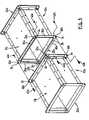
- FIG. 1is an isometric view of a rectangular duct system or assembly in accordance with the present invention
- FIG. 2is an exploded isometric view of the duct assembly shown in FIG. 1 ;
- FIG. 3is a longitudinal cross-sectional view of the duct assembly shown in FIG. 1 ;
- FIG. 4is a cross-sectional view of the duct assembly shown in FIG. 1 ;
- FIG. 5is an isometric view showing a mechanism for joining duct sections together according to the present invention.
- FIG. 6is a longitudinal cross-sectional view of the assembled duct sections shown in FIG. 5 .
- FIGS. 1 to 4show a fire-rated duct system in accordance with the present invention and indicated generally by reference 10 .
- like referencesindicate like elements or features.
- the fire-rated duct system 10is described in the context of an HVAC application, it is to be appreciated that the duct system 10 has wider applicability.
- the duct system 10is suitable for other applications including encasing or surrounding electrical wiring and wiring runs, plumbing runs, communication lines and data networks, in addition to smoke evacuation.
- the fire-rated duct system 10comprises an inner duct liner 12 , fire-resistant side panels 14 (shown individually as 14 a and 14 b ), and a fire-resistant top-bottom panel 16 (indicated individually by reference 16 a and 16 b ).
- the fire-rated duct system 10also includes corner angle sections 20 (indicated individually by references 20 a , 20 b , 20 c and 20 d ), and end connector frames 22 (indicated individually by references 22 a and 22 b ).
- the inner duct liner 12is fabricated from galvanized steel or other metal as required and is formed into a square or rectangular tube.
- the thickness of the galvanized steel used to fabricate the inner duct liner 12will vary by the size of the duct being fabricated and should be gauged in accordance with standard ASHRAE or SMACNA guidelines as a minimum.
- the inner duct liner 12 fabricated according to the guidelinesmay have thickness ranging between 26 gauge (i.e. on the thin side) to 18 gauge (i.e. on the thick side).
- the inner duct liner 12may be formed as follows: (a) forming one piece of metal into a tube; or (b) forming two pieces of metal into “L” shaped sections and joining them together; or (c) using four separate pieces or panels and joining them to form a tube.
- a male-female joint or lockis formed on the opposing longitudinal edges of the panels that are to be joined together. Due to the stresses that may be exerted during a fire, it is preferred that the longitudinal joint of the tube be of either a snap lock or a ‘Pittsburgh-type’ lock mechanism. If the snap lock is used, rivets are used for reinforcement through the male-female joint to prevent the male leg of the lock from popping out of the female pocket.
- the fire-resistant side panels 14 and the fire-resistant top-bottom panels 16are cut so that the corners of bottom-top panel 16 overlaps the side panel 14 at the corner by the thickness of the side panel 14 so as to form a closed corner.
- the fire-resistant side panels 14are attached to the inner liner 12 to form edges that are flush with the ends 18 of the inner duct liner 12 .
- the fire-resistant panels 14 and 16are attached to the inner liner 12 by drilling two holes 24 a and 24 b through the fire-resistant panel 16 and the inner liner 12 at the approximate midpoint of the inner liner 12 .
- the holes 24 a and 24 bmay be spaced approximately 6′′ to 8′′ (150 to 200 mm) apart.
- Steel or stainless steel rivets 26( FIG. 3 ) are inserted through the holes 24 a and 24 b and mechanically drawn tight which results in the inner liner 12 and the fire-resistant panels 14 , 16 being drawn together.
- a 1 ⁇ 8′′ (3 mm) bead of fire-resistant sealantis placed along the top and bottom longitudinal edges 15 of the side fire-resistant panels 14 a and 14 b . This serves to form a seal and fill any voids between the top 16 a and bottom 16 b fire-resistant panels and the side fire-resistant panels 14 a and 14 b . As described above, the end edges 17 of the top and bottom panels 16 a and 16 b are aligned with the end edges 19 of the side panels 14 a and 14 b.
- the corner angle members 20are fabricated from steel, for example, a flat light gauge galvanized steel, and are formed so as to create a 90 degree bend with equal legs 21 ( FIG. 2 ) measuring approximately 2′′ (50 mm).
- the corner angle members 20are installed over each of the corners formed by the longitudinal edges of the respective top and bottom fire-resistant panels 16 and the respective side fire-resistant panels 14 .
- the corner angle members 20create a finished corner and also a structure joint while minimizing thermal transfer.
- the corner angle members 20include holes for receiving fasteners 28 , such as rivets, as shown in FIGS. 1 and 3 .
- the holes in the corner angle members 20are aligned with respective holes in the fire-resistant panels 14 and 16 and in the inner duct liner 12 .
- the holes in the corner angle members 20may be punched during fabrication, or alternatively, the holes may be drilled through the corner angle members 20 , the respective fire-resistant panel 14 or 16 , and the inner liner 12 .
- the holesare located about 1′′ (50 mm) from the edge of the corner angle members 20 .
- additional holesare drilled on both legs 21 each of the corner angle members 20 at approximate 8′′ (200 mm) centers starting approximately 9′′ (225 mm) from the end 18 ( FIG. 2 ) of the inner liner 12 so that the spacing between the fasteners are equal.
- the fastener 28e.g.
- suitable fasteners 28include screws, bolts, and the like.
- the end connector frames 22comprise four flange profile sections 30 and four corner pieces 32 .
- the flange profile sections 30are indicated individually by references 30 a , 30 b , 30 c and 30 d
- the corner pieces 32are indicated individually by references 32 a , 32 b , 32 c and 32 d .
- the flange profiles 30are fabricated as roll formed flange and the corner pieces 32 are stamped using die fabrication techniques.
- the roll formed flange 30includes parallel legs 31 (shown as 31 a and 31 b in FIG. 2 ).
- the stamped corner piece 32has two equal legs 33 (indicated by references 33 a and 33 b and shown in broken outline in FIG.
- the parallel legs 31are formed having a spacing so that the leg 33 of the corner piece 32 is slid into place with a slight friction fit. The friction fit prevents the finished end connector frame 22 from being fabricated out of square.
- the two parallel legs 31( FIG. 2 ) are formed so that the distance between the inner 31 b and outer 31 a legs is equal to the mean thickness of the inner duct liner 12 and the fire-resistant panels 14 or 16 . This distance is consistent and should allow for the variances in the thickness of the inner liner 12 .
- the thickness of the inner liner 12may vary from a low of 0.021′′ (0.5 mm) to a high of 0.051′′ (1.3 mm).
- the duct sections 11(shown individually as 11 a and 11 b in FIG. 5 ) are connected together using the end connector frames 22 (shown individually as 22 a and 22 b in FIG. 5 ) as will be described in more detail below.
- each leg 33 of the corner piece 32has a shoulder 34 that terminates approximately 1 ⁇ 2′′ (12.5 mm) from the perpendicular leg.
- the shoulder 34provides a stop for the flange profile section 30 , when the leg 33 of the corner piece 32 is inserted between the parallel legs 31 of the flange profile section 30 .
- the inner leg 31 b of the roll formed flange profile 30does not interfere with the mechanical lock used on the inner liner 12 .
- each roll formed flange profile section 30is cut approximately 1′′ (25 mm) shorter than the inside dimension of the required duct section so that when the end connector frame 22 is assembled the distance between inner face of the legs 31 a of the opposing roll formed flange profile 30 is equal to the inside dimension of the inner duct liner 12 .
- each of the duct sections 11requires two complete end connector frames 22 .
- a bead of fire-resistant sealant 36Prior to installing each of the connector frames 22 , a bead of fire-resistant sealant 36 as shown in FIG. 4 .
- the fire-resistant sealant 36comprises a bead of about 1 ⁇ 4′′ to 3 ⁇ 8′′ (6–10 mm) which is injected between the horizontal legs 31 of each one of the roll formed flange profile sections 30 so that said bead is resting against the vertical leg 35 ( FIG. 4 ) of the flange profile section 30 .
- the connector frame 22is slid over the end of the duct section 11 and is pushed on until the end of the duct section 11 comes into contact with the corner pieces 32 of the connector frames 22 . At this point the end of the duct section 11 is also sealed to the connector frame 22 by embedding the end of the duct section 11 into the bead of the fire resistant sealant 36 .
- the connector frame 22is attached to the duct section 11 by drilling through the outer horizontal leg 31 b of the roll formed flange section 30 a at a point 1′′ (25 mm) from the edge of the leg and 1 ⁇ 2′′ (12 mm) from the end of the leg 31 b .
- the holeshould continue through the fire-resistant panel 16 a (or fire-resistant panel 14 for the sides of the duct section 11 ), through the inner duct liner 12 and through the inner horizontal leg 31 a of the flange section 30 a ( FIG. 3 ).
- a rivet 38is inserted into the hole and drawn tight by mechanical means so that the horizontal legs 31 of the flange section 30 a are pulled tight with the fire-resistant panel 16 a and the inner liner 12 to form the duct section 11 .
- Thisis repeated at the opposite end of the flange 30 a and at approximately 8′′ (200 mm) centers between the end attachments. This procedure is repeated for each of the flange sections 30 of the connector frame 22 .
- the rivets 38are substituted with removable fasteners such as a bolt and nut arrangement. This allows the flange sections 30 , i.e. the connector frame 22 , to be removed in the field or the connector frame 22 to be shipped separate from the duct system 10 which is assembled at a factory site.
- the connector frames 22 a and 22 bare typically attached to both ends of the duct section 11 (following the procedure as described with reference to FIG. 3 ) during fabrication at the factory prior to shipping.
- the duct section 11is shipped with one attached connector frame 22 , and one unattached connector frame 22 , for example, to permit the installation of the duct section 11 through an existing opening in the floor or wall.
- the uninstalled connector frame 22is then attached to the duct section 11 in the field in the manner as described above with reference to FIG. 3 .
- the longitudinal seams of the inner duct liner 12 and the interface between the inner duct liner 12 and the corner pieces 32should be sealed with the fire resistant sealant 36 , as used to seal the flange profile section 30 to the inner duct liner 12 (as described above) to create an airtight seal.
- FIGS. 5 and 6illustrate a method for connecting together a first duct section 11 a to a second duct section 11 b according to another aspect of the present invention.
- a fire resistant sealant 39is applied to the connector frame 22 of the first duct section 11 a .
- the fire-resistant sealant 39is applied to be located within the lower half of the flange sections 30 relative to the inner duct liner 12 .
- the fire-resistant sealantmay comprise either a mastic or a tape and is applied immediately prior to joining together the duct sections 11 a and 11 b .
- the second duct section 11 bis drawn towards the first section so that the holes 34 in the corner pieces 32 on the respective connector frames 22 are aligned.
- bolt fasteners 40(indicated individually as 40 a , 40 b , 40 c , 40 d ) and nut fasteners 42 (indicated individually as 42 a , 42 b , 42 c , 40 d ) are used to couple together adjacent connector frames 22 .
- the bolt 40 ais inserted through the holes 34 for respective corner pieces 32 a , and the nut 42 a is tightened finger tight.
- the bolts 40 b , 40 c , 40 d and the nuts 42 b , 42 c , 42 dare applied to the other corner pieces 32 b , 32 c , 32 d and finger tightened.
- Each of the bolts 40is then tightened with a wrench until snug and the mating faces of the respective corner pieces 32 are touching.
- the duct sections 11Due to the variety of sizes possible for the duct sections 11 , it may be necessary to install additional fasteners between adjacent corner pieces 32 , for example, the corner pieces 32 a and 32 d , and the corner pieces 32 b and 32 c .
- the additional fastenersare provided to prevent the flange sections 30 from separating at a midpoint between the corner bolts 40 , for example, during fire situations.
- the first mechanismcomprises a roll formed retention clip 50 .
- the shape of and roll forming process for fabricating the retention clip 50provides a spring-like force which securely holds the adjacent flange sections 30 together when the clip 50 is applied or snapped over the top edges of the flange sections 30 .
- the roll formed retention clips 50are approximately 6′′ (150 mm) long and mounted on approximate 12′′ (300 mm) centers. The length of the clip 50 and centers will vary due to the duct size.
- the second mechanismcomprises using self-drilling/self-tapping screws 60 .
- the screws 60are installed through the vertical legs of the roll formed flange pieces 30 .
- the screws 60are located approximately on center of the vertical legs and installed on approximately 6 to 8′′ (150 to 200 mm) centers.
- the fire-rated duct assembly 10is assembled at the factory and delivered to a job site.
- one or more of the connector flange ends 22may be removed (i.e. using removable fasteners) to permit the duct section 11 to be modified, e.g. cut to length or passed a precut opening, and then the connector flange member 22 is reconnected using the fasteners.
- the duct assembly 10is field modifiable without necessary voiding the UL rating or other certifications or approvals. This in turn prevents project delays due to the time needed for factory fabrication of sized duct sections.
- the duct assembly 10is shipped from the factory with one of the connector flange member 22 separate from the duct section 11 . This allows installation of the duct section 11 in the field, for example, through an existing or undersized opening in a wall or slab floor, that would not be possible with the connector flange member 22 installed on the duct section 11 .
Landscapes
- Engineering & Computer Science (AREA)
- General Engineering & Computer Science (AREA)
- Mechanical Engineering (AREA)
- Chemical & Material Sciences (AREA)
- Combustion & Propulsion (AREA)
- Building Environments (AREA)
- Duct Arrangements (AREA)
- Respiratory Apparatuses And Protective Means (AREA)
Abstract
Description
Claims (16)
Priority Applications (2)
| Application Number | Priority Date | Filing Date | Title |
|---|---|---|---|
| US10/705,967US7195290B2 (en) | 2003-11-13 | 2003-11-13 | Apparatus for a fire-rated duct |
| CA002450977ACA2450977C (en) | 2003-11-13 | 2003-11-26 | Apparatus for a fire-rated duct |
Applications Claiming Priority (1)
| Application Number | Priority Date | Filing Date | Title |
|---|---|---|---|
| US10/705,967US7195290B2 (en) | 2003-11-13 | 2003-11-13 | Apparatus for a fire-rated duct |
Publications (2)
| Publication Number | Publication Date |
|---|---|
| US20050116470A1 US20050116470A1 (en) | 2005-06-02 |
| US7195290B2true US7195290B2 (en) | 2007-03-27 |
Family
ID=34573375
Family Applications (1)
| Application Number | Title | Priority Date | Filing Date |
|---|---|---|---|
| US10/705,967Expired - LifetimeUS7195290B2 (en) | 2003-11-13 | 2003-11-13 | Apparatus for a fire-rated duct |
Country Status (2)
| Country | Link |
|---|---|
| US (1) | US7195290B2 (en) |
| CA (1) | CA2450977C (en) |
Cited By (17)
| Publication number | Priority date | Publication date | Assignee | Title |
|---|---|---|---|---|
| US20090022569A1 (en)* | 2007-07-18 | 2009-01-22 | Ram Developing Llc | Method and apparatus for attaching flange portions to ducts |
| US20090190307A1 (en)* | 2005-09-19 | 2009-07-30 | Chatsworth Products, Inc. | Ducted exhaust equipment enclosure |
| US20090309358A1 (en)* | 2008-06-12 | 2009-12-17 | Richard Gray | Air flow ducts |
| US20100061059A1 (en)* | 2005-09-19 | 2010-03-11 | Chatsworth Products, Inc. | Ducted exhaust equipment enclosure |
| US8685302B2 (en) | 2012-02-20 | 2014-04-01 | Honeywell International Inc. | Monolithic acoustically-treated composite structures and methods for fabricating the same |
| US8730665B2 (en) | 2005-09-19 | 2014-05-20 | Chatsworth Products, Inc. | Vertical exhaust duct |
| US9074788B2 (en) | 2012-01-06 | 2015-07-07 | William Christopher Duffy | Fire-rated modular duct assembly suitable for exhausting flammable or hazardous gases, vapours and other materials |
| US9371941B1 (en)* | 2013-11-06 | 2016-06-21 | Ptm Manufacturing, Llc | Exterior ductwork system |
| US10024569B2 (en) | 2013-10-10 | 2018-07-17 | William Christopher Duffy | Fire-rated modular duct assembly and improvements therein |
| CN110567216A (en)* | 2019-10-10 | 2019-12-13 | 王剑 | Long-acting refrigeration equipment for cold chain transportation |
| CN111059385A (en)* | 2020-01-09 | 2020-04-24 | 叶飞 | But quick connect's fire prevention air pipe for boats and ships |
| US10775072B2 (en) | 2016-03-03 | 2020-09-15 | Carrier Corporation | Cover channel, cover frame, insulating panel, air handling unit and method for manufacturing a cover channel |
| US10876757B2 (en) | 2018-05-01 | 2020-12-29 | Miles Volpe | Telescopic vent |
| US11212928B2 (en) | 2005-09-19 | 2021-12-28 | Chatsworth Products, Inc. | Vertical exhaust duct for electronic equipment enclosure |
| US11259446B2 (en) | 2005-09-19 | 2022-02-22 | Chatsworth Products, Inc. | Vertical exhaust duct for electronic equipment enclosure |
| US11397008B2 (en) | 2018-03-26 | 2022-07-26 | Van-Packer Company | Pre-fabricated grease duct system |
| US11549719B2 (en)* | 2016-07-25 | 2023-01-10 | Instad Pre Fabrication Pte Ltd | Duct panel |
Families Citing this family (27)
| Publication number | Priority date | Publication date | Assignee | Title |
|---|---|---|---|---|
| US7163030B2 (en)* | 2002-07-11 | 2007-01-16 | Jeffrey Allen Hermanson | Rectangular and square double wall ducting systems |
| US20090200801A1 (en)* | 2008-02-08 | 2009-08-13 | Shinfuji Kuuchou Co., Ltd. | Duct and the manufacturing method |
| US8276425B2 (en) | 2007-10-02 | 2012-10-02 | Mestek Machinery, Inc. | Ductmaking apparatus |
| US8499604B2 (en)* | 2008-10-01 | 2013-08-06 | Mestek Machinery, Inc. | Duct making apparatus and method |
| US9285066B2 (en)* | 2009-01-15 | 2016-03-15 | Cheminee Securite International Ltee | Positive pressure pipe coupling |
| US10539337B2 (en) | 2009-11-24 | 2020-01-21 | Jeffrey Allen Hermanson | Sealed and/or reinforced flanged ring connector for single- and double-wall HVAC ducting |
| WO2011066298A1 (en)* | 2009-11-24 | 2011-06-03 | Jeffrey Allen Hermanson | Standing seam connectors for ducting |
| SE535187C2 (en)* | 2010-09-10 | 2012-05-15 | Fumex Ab | Joint construction, ventilation arm and ventilation system |
| JP2013210166A (en)* | 2012-03-30 | 2013-10-10 | Nippon Light Metal Co Ltd | Frame body and tubular body |
| DE202012010570U1 (en)* | 2012-11-07 | 2012-11-27 | Berliner Wartungs- und Kundendienst GmbH | air duct |
| GB2514533B (en)* | 2013-03-08 | 2020-01-29 | Ronald Dalgarno Michael | Thermally insulated duct members |
| CA2948236C (en)* | 2014-05-07 | 2022-02-01 | Michael Ronald DALGARNO | Modular insulated ducting system |
| CN107980086B (en)* | 2015-02-23 | 2021-01-26 | 肯尼思·詹姆斯·达尔加诺 | Fire-proof pipeline system |
| CN105863092B (en)* | 2016-04-05 | 2018-05-18 | 上海十三冶建设有限公司 | A kind of installation method of smoke control system fire-proof plate |
| US10976070B1 (en) | 2017-03-31 | 2021-04-13 | Albers Mechanical Contractors, Inc. | Foam core duct system protected by metal sleeves with integral flanges |
| CN107084518B (en)* | 2017-05-22 | 2019-07-30 | 中国五冶集团有限公司 | Large-scale arc-shape wind pipe |
| US11441810B2 (en) | 2017-11-21 | 2022-09-13 | Durasystems Barriers Inc. | Pre-fabricated modular fire-rated conduit assembly |
| DE102018005993A1 (en)* | 2018-07-31 | 2020-02-06 | Karl-Heinz Rinklin | Fire-protected ventilation duct for building equipment |
| JP7185280B2 (en)* | 2019-01-22 | 2022-12-07 | 株式会社新富士空調 | Duct with reinforcing ribs |
| US11333390B2 (en)* | 2020-03-25 | 2022-05-17 | Durasystems Barriers Inc. | Fire-rated ventilation duct and improvements therein |
| US11739945B2 (en)* | 2020-12-10 | 2023-08-29 | Haier Us Appliance Solutions, Inc. | Oven appliance spill management system |
| CN112879655B (en)* | 2020-12-25 | 2022-06-21 | 成都建工工业设备安装有限公司 | Installation method for fire damper of parallel air pipe |
| US11781777B2 (en)* | 2021-01-22 | 2023-10-10 | Super Heat Incorporated | Ducting system for HVAC application |
| CN113776183B (en)* | 2021-09-13 | 2022-08-23 | 河北都创机电工程有限公司 | Air conditioner ventilation pipeline convenient to installation and dismantlement |
| CN115540316A (en)* | 2022-10-10 | 2022-12-30 | 中建八局第二建设有限公司 | Fireproof plate coating mechanism of smoke-proof and exhaust-proof air pipe |
| CN118031343B (en)* | 2024-04-07 | 2024-07-19 | 广州品发机电科技有限公司 | Multifunctional full-automatic composite air pipe |
| CN118998456B (en)* | 2024-10-23 | 2024-12-20 | 山东迈凯诺安防科技有限公司 | An integrated floating bead silicon crystal refractory air duct |
Citations (51)
| Publication number | Priority date | Publication date | Assignee | Title |
|---|---|---|---|---|
| US2183174A (en)* | 1937-03-15 | 1939-12-12 | Smith Robert Wiley | Insulated duct construction |
| US2226523A (en)* | 1940-01-06 | 1940-12-24 | Wm Burchenal | Conduit construction |
| US3198561A (en) | 1963-05-13 | 1965-08-03 | W M Anderson Company | High pressure duct connection |
| US3630549A (en) | 1970-01-22 | 1971-12-28 | John A Grimm | Frame and cleat joint connector for ducts |
| US3800846A (en)* | 1972-02-14 | 1974-04-02 | J Kurz | Fire damper duct adaptor |
| US3811714A (en)* | 1972-04-24 | 1974-05-21 | Johns Manville | Corner adaptors for expansion joints |
| US3923326A (en) | 1974-01-04 | 1975-12-02 | Georg Mez | Flange connection |
| US4133566A (en) | 1977-06-23 | 1979-01-09 | Miller Robert B | High pressure duct clamp and method of use |
| US4380188A (en)* | 1981-01-28 | 1983-04-19 | Barber-Colman Company | Heat-retarding air distribution unit |
| US4509778A (en) | 1982-12-06 | 1985-04-09 | Ductmate Industries | Duct joint assembly |
| US4537430A (en) | 1978-10-19 | 1985-08-27 | Exanno Products Limited | Duct joining system |
| US4557297A (en)* | 1983-03-07 | 1985-12-10 | Bisco Products, Inc. | Flue gas duct assembly |
| US4572553A (en) | 1983-12-30 | 1986-02-25 | Siegfried Geldner | Flange connector |
| US4662661A (en)* | 1978-01-26 | 1987-05-05 | Ductmate Industries, Inc. | Flange type duct joint assembly and seal arrangement therefor |
| US4725083A (en)* | 1985-04-06 | 1988-02-16 | Michael Komotzki | Flanged joint for two sheet material air channel sections of rectangular cross section |
| US4765375A (en) | 1986-01-30 | 1988-08-23 | Kenji Nakajima | Duct |
| US4804207A (en)* | 1987-01-24 | 1989-02-14 | Metallpraecis Berchem | Connector pipe segment |
| US4836585A (en) | 1986-06-04 | 1989-06-06 | Markfield Schauer | Shaped flange for connecting air duct segments |
| US4940264A (en)* | 1983-04-13 | 1990-07-10 | Georg Mez | Flange connection |
| US5069484A (en) | 1990-02-09 | 1991-12-03 | Met-Coil Systems Corporation | Duct joining system |
| US5103549A (en) | 1988-06-10 | 1992-04-14 | Ductmate Industries, Inc. | Method for connecting the ends of a pair of oval duct sections |
| US5129690A (en) | 1988-06-10 | 1992-07-14 | Ductmate Industries, Inc. | Apparatus for connecting the ends of a pair of oval duct sections |
| US5133580A (en) | 1990-02-17 | 1992-07-28 | Metu-System Meinig Kg | Butt connection between two air duct sections made sheet of metal |
| US5135270A (en) | 1988-06-10 | 1992-08-04 | Ductmate Industries, Inc. | Apparatus for connecting the ends of a pair of oval duct sections |
| US5171184A (en)* | 1991-08-21 | 1992-12-15 | Press Mechanical, Inc. | Tensioned fire damper assembly and method |
| US5219403A (en)* | 1990-02-14 | 1993-06-15 | Gerard C. Murphy | Plastic self-insulating ductwork system |
| US5378028A (en) | 1993-01-25 | 1995-01-03 | Mez Industries, Inc. | Apparatus for connecting oval duct sections |
| GB2284989A (en) | 1993-12-03 | 1995-06-28 | Winstone Wallboards Ltd | Protecting ducts against fire |
| US5450879A (en)* | 1994-06-14 | 1995-09-19 | Met-Coil Systems Corporation | Cornerless slip-on flange system for duct connections |
| JPH08178404A (en) | 1994-12-20 | 1996-07-12 | Takasago Thermal Eng Co Ltd | Air conditioning and smoke exhaust ducts |
| US5564758A (en) | 1995-01-17 | 1996-10-15 | Century Manufacturing Co., Inc. | Angled plates for connecting ducts |
| US5575131A (en)* | 1993-02-25 | 1996-11-19 | National Gypsum Company | Multiple use corner clip |
| US5653482A (en) | 1995-12-15 | 1997-08-05 | Ficchi, Jr.; Vincent | Seal system for duct network |
| US5673947A (en) | 1994-04-22 | 1997-10-07 | De Waal Staal B.V. | Device for butt joining of ducts for carrying gaseous medium and having a rectangular or square cross section |
| US5775414A (en)* | 1996-06-13 | 1998-07-07 | Graham; Robert G. | High temperature high pressure air-to-air heat exchangers and assemblies useful therein |
| US5865478A (en)* | 1997-05-22 | 1999-02-02 | Lin; Hung Da | Coupling device for duct |
| US6109665A (en) | 1995-12-21 | 2000-08-29 | Metu-System Meining Kg | Butt joint of air duct sections |
| US6148867A (en)* | 1995-09-14 | 2000-11-21 | Johns Manville International, Inc. | Duct liners |
| US6213522B1 (en)* | 1998-12-31 | 2001-04-10 | Certainteed Corporation | Device for securing adjacent segments of fibrous glass duct work and the like and a system including said device |
| US6231704B1 (en)* | 1997-07-14 | 2001-05-15 | David J. Carpinetti | Apparatus for on-site installation of air duct system |
| US6412519B1 (en) | 2001-01-24 | 2002-07-02 | Met-Coil Systems Corporation | Duct connecting system having double walled transverse flanges |
| US20020121778A1 (en) | 2001-03-01 | 2002-09-05 | Staffan Tigerfeldt | Ventilation duct construction and method |
| US6460573B1 (en) | 2000-01-31 | 2002-10-08 | Engel Industries | Companion duct system |
| US6471256B1 (en) | 2000-01-31 | 2002-10-29 | Engel Industries, Inc. | Companion duct flanges |
| US6502716B1 (en)* | 2001-04-10 | 2003-01-07 | John R. Kolesar | Duct corner dispenser and method of dispensing duct corners |
| US20030006611A1 (en) | 2001-07-03 | 2003-01-09 | Shuey Alan B. | Fabricated oval duct connector |
| US6547287B1 (en) | 2001-10-11 | 2003-04-15 | Met-Coil Systems Corporation | Duct connecting system having integral transverse flanges |
| US6550823B1 (en) | 1999-08-05 | 2003-04-22 | Emil Siegwart | Flange connection for pipes, in particular, air pipes |
| US6561553B1 (en) | 1999-11-16 | 2003-05-13 | Robert Issagholian-Havai | Angle plate fastening method and apparatus for air duct flange connectors |
| US20030160452A1 (en) | 2001-01-17 | 2003-08-28 | Lindab Ab | Coupling ring for ventilation ducts, and method of connecting ventilation ducts |
| US6848720B2 (en)* | 2002-08-09 | 2005-02-01 | The Boeing Company | Shrouded fluid-conducting apparatus |
- 2003
- 2003-11-13USUS10/705,967patent/US7195290B2/ennot_activeExpired - Lifetime
- 2003-11-26CACA002450977Apatent/CA2450977C/ennot_activeExpired - Lifetime
Patent Citations (54)
| Publication number | Priority date | Publication date | Assignee | Title |
|---|---|---|---|---|
| US2183174A (en)* | 1937-03-15 | 1939-12-12 | Smith Robert Wiley | Insulated duct construction |
| US2226523A (en)* | 1940-01-06 | 1940-12-24 | Wm Burchenal | Conduit construction |
| US3198561A (en) | 1963-05-13 | 1965-08-03 | W M Anderson Company | High pressure duct connection |
| US3630549A (en) | 1970-01-22 | 1971-12-28 | John A Grimm | Frame and cleat joint connector for ducts |
| US3800846A (en)* | 1972-02-14 | 1974-04-02 | J Kurz | Fire damper duct adaptor |
| US3811714A (en)* | 1972-04-24 | 1974-05-21 | Johns Manville | Corner adaptors for expansion joints |
| US3923326A (en) | 1974-01-04 | 1975-12-02 | Georg Mez | Flange connection |
| US4133566A (en) | 1977-06-23 | 1979-01-09 | Miller Robert B | High pressure duct clamp and method of use |
| US4662661B1 (en)* | 1978-01-26 | 1997-05-13 | Ductmate Ind Inc | Flange type duct joint assembly and seal arrangement therefor |
| US4662661A (en)* | 1978-01-26 | 1987-05-05 | Ductmate Industries, Inc. | Flange type duct joint assembly and seal arrangement therefor |
| US4537430A (en) | 1978-10-19 | 1985-08-27 | Exanno Products Limited | Duct joining system |
| US4380188A (en)* | 1981-01-28 | 1983-04-19 | Barber-Colman Company | Heat-retarding air distribution unit |
| US4509778A (en) | 1982-12-06 | 1985-04-09 | Ductmate Industries | Duct joint assembly |
| US4557297A (en)* | 1983-03-07 | 1985-12-10 | Bisco Products, Inc. | Flue gas duct assembly |
| US4940264A (en)* | 1983-04-13 | 1990-07-10 | Georg Mez | Flange connection |
| US4572553A (en) | 1983-12-30 | 1986-02-25 | Siegfried Geldner | Flange connector |
| US4725083A (en)* | 1985-04-06 | 1988-02-16 | Michael Komotzki | Flanged joint for two sheet material air channel sections of rectangular cross section |
| US4765375A (en) | 1986-01-30 | 1988-08-23 | Kenji Nakajima | Duct |
| US4836585A (en) | 1986-06-04 | 1989-06-06 | Markfield Schauer | Shaped flange for connecting air duct segments |
| US4804207A (en)* | 1987-01-24 | 1989-02-14 | Metallpraecis Berchem | Connector pipe segment |
| US5103549A (en) | 1988-06-10 | 1992-04-14 | Ductmate Industries, Inc. | Method for connecting the ends of a pair of oval duct sections |
| US5129690A (en) | 1988-06-10 | 1992-07-14 | Ductmate Industries, Inc. | Apparatus for connecting the ends of a pair of oval duct sections |
| US5135270A (en) | 1988-06-10 | 1992-08-04 | Ductmate Industries, Inc. | Apparatus for connecting the ends of a pair of oval duct sections |
| US5069484A (en) | 1990-02-09 | 1991-12-03 | Met-Coil Systems Corporation | Duct joining system |
| US5219403A (en)* | 1990-02-14 | 1993-06-15 | Gerard C. Murphy | Plastic self-insulating ductwork system |
| US5133580A (en) | 1990-02-17 | 1992-07-28 | Metu-System Meinig Kg | Butt connection between two air duct sections made sheet of metal |
| US5171184A (en)* | 1991-08-21 | 1992-12-15 | Press Mechanical, Inc. | Tensioned fire damper assembly and method |
| US5378028A (en) | 1993-01-25 | 1995-01-03 | Mez Industries, Inc. | Apparatus for connecting oval duct sections |
| US5575131A (en)* | 1993-02-25 | 1996-11-19 | National Gypsum Company | Multiple use corner clip |
| GB2284989A (en) | 1993-12-03 | 1995-06-28 | Winstone Wallboards Ltd | Protecting ducts against fire |
| US5673947A (en) | 1994-04-22 | 1997-10-07 | De Waal Staal B.V. | Device for butt joining of ducts for carrying gaseous medium and having a rectangular or square cross section |
| US5450879A (en)* | 1994-06-14 | 1995-09-19 | Met-Coil Systems Corporation | Cornerless slip-on flange system for duct connections |
| JPH08178404A (en) | 1994-12-20 | 1996-07-12 | Takasago Thermal Eng Co Ltd | Air conditioning and smoke exhaust ducts |
| US5564758A (en) | 1995-01-17 | 1996-10-15 | Century Manufacturing Co., Inc. | Angled plates for connecting ducts |
| US6148867A (en)* | 1995-09-14 | 2000-11-21 | Johns Manville International, Inc. | Duct liners |
| US5653482A (en) | 1995-12-15 | 1997-08-05 | Ficchi, Jr.; Vincent | Seal system for duct network |
| US6109665A (en) | 1995-12-21 | 2000-08-29 | Metu-System Meining Kg | Butt joint of air duct sections |
| US5775414A (en)* | 1996-06-13 | 1998-07-07 | Graham; Robert G. | High temperature high pressure air-to-air heat exchangers and assemblies useful therein |
| US5865478A (en)* | 1997-05-22 | 1999-02-02 | Lin; Hung Da | Coupling device for duct |
| US6231704B1 (en)* | 1997-07-14 | 2001-05-15 | David J. Carpinetti | Apparatus for on-site installation of air duct system |
| US6213522B1 (en)* | 1998-12-31 | 2001-04-10 | Certainteed Corporation | Device for securing adjacent segments of fibrous glass duct work and the like and a system including said device |
| US6550823B1 (en) | 1999-08-05 | 2003-04-22 | Emil Siegwart | Flange connection for pipes, in particular, air pipes |
| US6561553B1 (en) | 1999-11-16 | 2003-05-13 | Robert Issagholian-Havai | Angle plate fastening method and apparatus for air duct flange connectors |
| US6460573B1 (en) | 2000-01-31 | 2002-10-08 | Engel Industries | Companion duct system |
| US6471256B1 (en) | 2000-01-31 | 2002-10-29 | Engel Industries, Inc. | Companion duct flanges |
| US20030160452A1 (en) | 2001-01-17 | 2003-08-28 | Lindab Ab | Coupling ring for ventilation ducts, and method of connecting ventilation ducts |
| US6758502B2 (en) | 2001-01-17 | 2004-07-06 | Lindab Ab | Coupling ring for ventilation ducts, and method of connecting ventilation ducts |
| US6412519B1 (en) | 2001-01-24 | 2002-07-02 | Met-Coil Systems Corporation | Duct connecting system having double walled transverse flanges |
| US20020121778A1 (en) | 2001-03-01 | 2002-09-05 | Staffan Tigerfeldt | Ventilation duct construction and method |
| US6502716B1 (en)* | 2001-04-10 | 2003-01-07 | John R. Kolesar | Duct corner dispenser and method of dispensing duct corners |
| US20030006611A1 (en) | 2001-07-03 | 2003-01-09 | Shuey Alan B. | Fabricated oval duct connector |
| US6505864B1 (en) | 2001-07-03 | 2003-01-14 | Ductmate Industries, Inc. | Fabricated oval duct connector |
| US6547287B1 (en) | 2001-10-11 | 2003-04-15 | Met-Coil Systems Corporation | Duct connecting system having integral transverse flanges |
| US6848720B2 (en)* | 2002-08-09 | 2005-02-01 | The Boeing Company | Shrouded fluid-conducting apparatus |
Non-Patent Citations (1)
| Title |
|---|
| Canadian Office Action, dated Aug. 2, 2006, Canadian Patent Application No. 2,450,977 (3 pages). |
Cited By (49)
| Publication number | Priority date | Publication date | Assignee | Title |
|---|---|---|---|---|
| US11212928B2 (en) | 2005-09-19 | 2021-12-28 | Chatsworth Products, Inc. | Vertical exhaust duct for electronic equipment enclosure |
| US11547020B2 (en) | 2005-09-19 | 2023-01-03 | Chatsworth Products, Inc. | Vertical exhaust duct for electronic equipment enclosure |
| US12082379B2 (en) | 2005-09-19 | 2024-09-03 | Chatsworth Products, Inc. | Vertical exhaust duct for electronic equipment enclosure |
| US20100061059A1 (en)* | 2005-09-19 | 2010-03-11 | Chatsworth Products, Inc. | Ducted exhaust equipment enclosure |
| US7804685B2 (en)* | 2005-09-19 | 2010-09-28 | Chatsworth Products, Inc. | Ducted exhaust equipment enclosure |
| US11785745B2 (en) | 2005-09-19 | 2023-10-10 | Chatsworth Products, Inc. | Vertical exhaust duct for electronic equipment enclosure |
| US11678447B2 (en) | 2005-09-19 | 2023-06-13 | Chatsworth Products, Inc. | Vertical exhaust duct for electronic equipment enclosure |
| US8107238B2 (en) | 2005-09-19 | 2012-01-31 | Chatsworth Products, Inc. | Ducted exhaust equipment enclosure |
| US10334761B2 (en) | 2005-09-19 | 2019-06-25 | Chatsworth Products, Inc. | Method of venting heated air from electronic equipment enclosure |
| US8730665B2 (en) | 2005-09-19 | 2014-05-20 | Chatsworth Products, Inc. | Vertical exhaust duct |
| US8737068B2 (en) | 2005-09-19 | 2014-05-27 | Chatsworth Products, Inc. | Ducted exhaust equipment enclosure |
| US11259446B2 (en) | 2005-09-19 | 2022-02-22 | Chatsworth Products, Inc. | Vertical exhaust duct for electronic equipment enclosure |
| US9084369B2 (en) | 2005-09-19 | 2015-07-14 | Chatsworth Products, Inc. | Vertical exhaust duct |
| US9119329B2 (en) | 2005-09-19 | 2015-08-25 | Chatsworth Products, Inc. | Ducted exhaust equipment enclosure |
| US10791640B2 (en) | 2005-09-19 | 2020-09-29 | Chatsworth Products, Inc. | Vertical exhaust duct for electronic equipment enclosure |
| US10765037B2 (en) | 2005-09-19 | 2020-09-01 | Chatsworth Products, Inc. | Vertical exhaust duct for electronic equipment enclosure |
| US10624232B2 (en) | 2005-09-19 | 2020-04-14 | Chatsworth Products, Inc. | Ducted exhaust equipment enclosure |
| US10568239B2 (en) | 2005-09-19 | 2020-02-18 | Chatsworth Products, Inc. | Method of venting heated air from electronic equipment enclosure |
| US10440847B2 (en) | 2005-09-19 | 2019-10-08 | Chatsworth Products, Inc. | Vertical exhaust duct for electronic equipment enclosure |
| US9801309B2 (en) | 2005-09-19 | 2017-10-24 | Chatsworth Products, Inc. | Ducted exhaust equipment enclosure |
| US9974198B2 (en) | 2005-09-19 | 2018-05-15 | Chatsworth Products, Inc. | Vertical exhaust duct for electronic equipment enclosure |
| US20090190307A1 (en)* | 2005-09-19 | 2009-07-30 | Chatsworth Products, Inc. | Ducted exhaust equipment enclosure |
| US10123462B2 (en) | 2005-09-19 | 2018-11-06 | Chatsworth Products, Inc. | Ducted exhaust equipment enclosure |
| US9212770B2 (en)* | 2007-07-18 | 2015-12-15 | RAM Developing, LLC | Method and apparatus for attaching flange portions to ducts |
| US20090022569A1 (en)* | 2007-07-18 | 2009-01-22 | Ram Developing Llc | Method and apparatus for attaching flange portions to ducts |
| US10180264B2 (en) | 2007-07-18 | 2019-01-15 | Ram Developing Llc | Method and apparatus for attaching flange portions to ducts |
| US20090309358A1 (en)* | 2008-06-12 | 2009-12-17 | Richard Gray | Air flow ducts |
| US8040673B2 (en) | 2008-09-08 | 2011-10-18 | Chatsworth Products, Inc. | Ducted exhaust equipment enclosure |
| US11706898B2 (en) | 2008-09-08 | 2023-07-18 | Chatsworth Products, Inc. | Ducted exhaust equipment enclosure |
| US20120013229A1 (en)* | 2008-09-08 | 2012-01-19 | William Krietzman | Ducted exhaust equipment enclosure |
| US11464132B2 (en) | 2008-09-08 | 2022-10-04 | Chatsworth Products, Inc. | Ducted exhaust equipment enclosure |
| US12052843B2 (en) | 2008-09-08 | 2024-07-30 | Chatsworth Products, Inc. | Ducted exhaust equipment enclosure |
| US9557071B2 (en) | 2012-01-06 | 2017-01-31 | William Christopher Duffy | Fire-rated modular duct assembly suitable for exhausting flammable or hazardous gases, vapours and other materials |
| US9074788B2 (en) | 2012-01-06 | 2015-07-07 | William Christopher Duffy | Fire-rated modular duct assembly suitable for exhausting flammable or hazardous gases, vapours and other materials |
| USRE50587E1 (en) | 2012-01-06 | 2025-09-16 | Vaughanair Canada Ulc | Fire-rated modular duct assembly suitable for exhausting flammable or hazardous gases, vapours and other materials |
| USRE49087E1 (en) | 2012-01-06 | 2022-05-31 | Durasystems Barriers Inc. | Fire-rated modular duct assembly suitable for exhausting flammable or hazardous gases, vapours and other materials |
| US9976768B2 (en) | 2012-01-06 | 2018-05-22 | DuraSystems | Fire-rated modular duct assembly suitable for exhausting flammable or hazardous gases, vapours and other materials |
| US9469390B2 (en) | 2012-02-20 | 2016-10-18 | Honeywell International Inc. | Monolithic acoustically-treated composite structures and methods for fabricating the same |
| US8685302B2 (en) | 2012-02-20 | 2014-04-01 | Honeywell International Inc. | Monolithic acoustically-treated composite structures and methods for fabricating the same |
| US10024569B2 (en) | 2013-10-10 | 2018-07-17 | William Christopher Duffy | Fire-rated modular duct assembly and improvements therein |
| US9371941B1 (en)* | 2013-11-06 | 2016-06-21 | Ptm Manufacturing, Llc | Exterior ductwork system |
| US9709296B1 (en) | 2013-11-06 | 2017-07-18 | Ptm Manufacturing, Llc | Ductwork system |
| US10775072B2 (en) | 2016-03-03 | 2020-09-15 | Carrier Corporation | Cover channel, cover frame, insulating panel, air handling unit and method for manufacturing a cover channel |
| US11549719B2 (en)* | 2016-07-25 | 2023-01-10 | Instad Pre Fabrication Pte Ltd | Duct panel |
| US11397008B2 (en) | 2018-03-26 | 2022-07-26 | Van-Packer Company | Pre-fabricated grease duct system |
| US10876757B2 (en) | 2018-05-01 | 2020-12-29 | Miles Volpe | Telescopic vent |
| CN110567216A (en)* | 2019-10-10 | 2019-12-13 | 王剑 | Long-acting refrigeration equipment for cold chain transportation |
| CN111059385A (en)* | 2020-01-09 | 2020-04-24 | 叶飞 | But quick connect's fire prevention air pipe for boats and ships |
| CN111059385B (en)* | 2020-01-09 | 2020-12-18 | 江苏丰源船舶工程有限公司 | But quick connect's fire prevention air pipe for boats and ships |
Also Published As
| Publication number | Publication date |
|---|---|
| CA2450977A1 (en) | 2005-05-13 |
| CA2450977C (en) | 2007-10-16 |
| US20050116470A1 (en) | 2005-06-02 |
Similar Documents
| Publication | Publication Date | Title |
|---|---|---|
| US7195290B2 (en) | Apparatus for a fire-rated duct | |
| US11339567B2 (en) | Fire-retardant panel with frame | |
| US7797893B2 (en) | Apparatus for reinforcing and firestopping around a duct extending through a structural panel | |
| US6105334A (en) | Fire resistant lighting enclosure | |
| US10920416B2 (en) | Drywall and sealing device for sealing a connection joint of a drywall | |
| US12152802B2 (en) | Fire-rated ventilation duct and improvements therein | |
| US9273462B2 (en) | System and method of manufacture for building panels | |
| US7685792B2 (en) | Apparatus for enhancing reinforcing and firestopping around a duct extending through a structural panel | |
| US7856775B2 (en) | Thermal insulation and sealing means for a safing slot | |
| JP4049564B2 (en) | Fireproof partition wall and its construction method | |
| US11713903B2 (en) | Ducting systems | |
| US20150176274A1 (en) | System and method for lateral transfer plate having a punched tab | |
| RU2767836C1 (en) | Construction system and method for building a structure | |
| Brandon et al. | Mitigation of fire damages in multi-storey timber buildings: Statistical analysis and guidelines for design | |
| US9428904B2 (en) | Modular joint barrier retainer assembly and method | |
| WO2021189125A1 (en) | Fire-rated ventilation duct and improvements therein | |
| CA3163189A1 (en) | A fire resistant ventilation duct and a method of manufacturing and installing such ventilation duct | |
| AU2017101778B4 (en) | A firestopping device and associated method | |
| US7140646B2 (en) | Shield for wall penetration of flexible tubing | |
| JP3169526B2 (en) | Fireproof building boards | |
| Mikkola et al. | Prevention of fire spread within structures | |
| Wemhoff | Model Code for the Prevention of Residential HAC Distribution System Leakage and HAC-Induced Building Leakage | |
| Wemhoff | Model Code for the Control of Residential HVAC Distribution System Leakage and HVAC-Induced Building Leakage | |
| JPH04258454A (en) | Panel constructing method | |
| JP2006207296A (en) | Fire stop structure in frame method |
Legal Events
| Date | Code | Title | Description |
|---|---|---|---|
| STCF | Information on status: patent grant | Free format text:PATENTED CASE | |
| FPAY | Fee payment | Year of fee payment:4 | |
| FPAY | Fee payment | Year of fee payment:8 | |
| FEPP | Fee payment procedure | Free format text:MAINTENANCE FEE REMINDER MAILED (ORIGINAL EVENT CODE: REM.); ENTITY STATUS OF PATENT OWNER: SMALL ENTITY | |
| FEPP | Fee payment procedure | Free format text:11.5 YR SURCHARGE- LATE PMT W/IN 6 MO, SMALL ENTITY (ORIGINAL EVENT CODE: M2556); ENTITY STATUS OF PATENT OWNER: SMALL ENTITY | |
| MAFP | Maintenance fee payment | Free format text:PAYMENT OF MAINTENANCE FEE, 12TH YR, SMALL ENTITY (ORIGINAL EVENT CODE: M2553); ENTITY STATUS OF PATENT OWNER: SMALL ENTITY Year of fee payment:12 | |
| AS | Assignment | Owner name:DURASYSTEMS BARRIERS INC., CANADA Free format text:ASSIGNMENT OF ASSIGNORS INTEREST;ASSIGNOR:DUFFY, WILLIAM CHRISTOPHER;REEL/FRAME:051133/0086 Effective date:20191127 | |
| AS | Assignment | Owner name:VAUGHANAIR CANADA ULC, MARYLAND Free format text:ASSIGNMENT OF ASSIGNORS INTEREST;ASSIGNOR:DURASYSTEMS BARRIERS INC.;REEL/FRAME:068137/0383 Effective date:20240624 | |
| AS | Assignment | Owner name:M&T BANK, NEW YORK Free format text:SECURITY INTEREST;ASSIGNOR:VAUGHANAIR CANADA ULC;REEL/FRAME:068262/0031 Effective date:20240624 |