US7195250B2 - Surface vehicle vertical trajectory planning - Google Patents
Surface vehicle vertical trajectory planningDownload PDFInfo
- Publication number
- US7195250B2 US7195250B2US10/629,243US62924303AUS7195250B2US 7195250 B2US7195250 B2US 7195250B2US 62924303 AUS62924303 AUS 62924303AUS 7195250 B2US7195250 B2US 7195250B2
- Authority
- US
- United States
- Prior art keywords
- profile
- vehicle
- storage device
- profiles
- microprocessor
- Prior art date
- Legal status (The legal status is an assumption and is not a legal conclusion. Google has not performed a legal analysis and makes no representation as to the accuracy of the status listed.)
- Expired - Lifetime, expires
Links
Images


Classifications
- G—PHYSICS
- G01—MEASURING; TESTING
- G01C—MEASURING DISTANCES, LEVELS OR BEARINGS; SURVEYING; NAVIGATION; GYROSCOPIC INSTRUMENTS; PHOTOGRAMMETRY OR VIDEOGRAMMETRY
- G01C21/00—Navigation; Navigational instruments not provided for in groups G01C1/00 - G01C19/00
- G01C21/26—Navigation; Navigational instruments not provided for in groups G01C1/00 - G01C19/00 specially adapted for navigation in a road network
- B—PERFORMING OPERATIONS; TRANSPORTING
- B60—VEHICLES IN GENERAL
- B60G—VEHICLE SUSPENSION ARRANGEMENTS
- B60G17/00—Resilient suspensions having means for adjusting the spring or vibration-damper characteristics, for regulating the distance between a supporting surface and a sprung part of vehicle or for locking suspension during use to meet varying vehicular or surface conditions, e.g. due to speed or load
- B60G17/015—Resilient suspensions having means for adjusting the spring or vibration-damper characteristics, for regulating the distance between a supporting surface and a sprung part of vehicle or for locking suspension during use to meet varying vehicular or surface conditions, e.g. due to speed or load the regulating means comprising electric or electronic elements
- B60G17/0195—Resilient suspensions having means for adjusting the spring or vibration-damper characteristics, for regulating the distance between a supporting surface and a sprung part of vehicle or for locking suspension during use to meet varying vehicular or surface conditions, e.g. due to speed or load the regulating means comprising electric or electronic elements characterised by the regulation being combined with other vehicle control systems
- B—PERFORMING OPERATIONS; TRANSPORTING
- B60—VEHICLES IN GENERAL
- B60G—VEHICLE SUSPENSION ARRANGEMENTS
- B60G17/00—Resilient suspensions having means for adjusting the spring or vibration-damper characteristics, for regulating the distance between a supporting surface and a sprung part of vehicle or for locking suspension during use to meet varying vehicular or surface conditions, e.g. due to speed or load
- B60G17/015—Resilient suspensions having means for adjusting the spring or vibration-damper characteristics, for regulating the distance between a supporting surface and a sprung part of vehicle or for locking suspension during use to meet varying vehicular or surface conditions, e.g. due to speed or load the regulating means comprising electric or electronic elements
- B60G17/016—Resilient suspensions having means for adjusting the spring or vibration-damper characteristics, for regulating the distance between a supporting surface and a sprung part of vehicle or for locking suspension during use to meet varying vehicular or surface conditions, e.g. due to speed or load the regulating means comprising electric or electronic elements characterised by their responsiveness, when the vehicle is travelling, to specific motion, a specific condition, or driver input
- B60G17/0165—Resilient suspensions having means for adjusting the spring or vibration-damper characteristics, for regulating the distance between a supporting surface and a sprung part of vehicle or for locking suspension during use to meet varying vehicular or surface conditions, e.g. due to speed or load the regulating means comprising electric or electronic elements characterised by their responsiveness, when the vehicle is travelling, to specific motion, a specific condition, or driver input to an external condition, e.g. rough road surface, side wind
- G—PHYSICS
- G01—MEASURING; TESTING
- G01C—MEASURING DISTANCES, LEVELS OR BEARINGS; SURVEYING; NAVIGATION; GYROSCOPIC INSTRUMENTS; PHOTOGRAMMETRY OR VIDEOGRAMMETRY
- G01C7/00—Tracing profiles
- G01C7/02—Tracing profiles of land surfaces
- G01C7/04—Tracing profiles of land surfaces involving a vehicle which moves along the profile to be traced
- B—PERFORMING OPERATIONS; TRANSPORTING
- B60—VEHICLES IN GENERAL
- B60G—VEHICLE SUSPENSION ARRANGEMENTS
- B60G2400/00—Indexing codes relating to detected, measured or calculated conditions or factors
- B60G2400/80—Exterior conditions
- B60G2400/82—Ground surface
- B60G2400/821—Uneven, rough road sensing affecting vehicle body vibration
- B—PERFORMING OPERATIONS; TRANSPORTING
- B60—VEHICLES IN GENERAL
- B60G—VEHICLE SUSPENSION ARRANGEMENTS
- B60G2400/00—Indexing codes relating to detected, measured or calculated conditions or factors
- B60G2400/80—Exterior conditions
- B60G2400/82—Ground surface
- B60G2400/824—Travel path sensing; Track monitoring
- B—PERFORMING OPERATIONS; TRANSPORTING
- B60—VEHICLES IN GENERAL
- B60G—VEHICLE SUSPENSION ARRANGEMENTS
- B60G2401/00—Indexing codes relating to the type of sensors based on the principle of their operation
- B60G2401/16—GPS track data
- B—PERFORMING OPERATIONS; TRANSPORTING
- B60—VEHICLES IN GENERAL
- B60G—VEHICLE SUSPENSION ARRANGEMENTS
- B60G2500/00—Indexing codes relating to the regulated action or device
- B60G2500/20—Spring action or springs
- B—PERFORMING OPERATIONS; TRANSPORTING
- B60—VEHICLES IN GENERAL
- B60G—VEHICLE SUSPENSION ARRANGEMENTS
- B60G2600/00—Indexing codes relating to particular elements, systems or processes used on suspension systems or suspension control systems
- B60G2600/18—Automatic control means
- B60G2600/182—Active control means
- B—PERFORMING OPERATIONS; TRANSPORTING
- B60—VEHICLES IN GENERAL
- B60G—VEHICLE SUSPENSION ARRANGEMENTS
- B60G2600/00—Indexing codes relating to particular elements, systems or processes used on suspension systems or suspension control systems
- B60G2600/18—Automatic control means
- B60G2600/187—Digital Controller Details and Signal Treatment
- B60G2600/1876—Artificial intelligence
- B—PERFORMING OPERATIONS; TRANSPORTING
- B60—VEHICLES IN GENERAL
- B60G—VEHICLE SUSPENSION ARRANGEMENTS
- B60G2600/00—Indexing codes relating to particular elements, systems or processes used on suspension systems or suspension control systems
- B60G2600/18—Automatic control means
- B60G2600/187—Digital Controller Details and Signal Treatment
- B60G2600/1877—Adaptive Control
- B—PERFORMING OPERATIONS; TRANSPORTING
- B60—VEHICLES IN GENERAL
- B60G—VEHICLE SUSPENSION ARRANGEMENTS
- B60G2600/00—Indexing codes relating to particular elements, systems or processes used on suspension systems or suspension control systems
- B60G2600/18—Automatic control means
- B60G2600/187—Digital Controller Details and Signal Treatment
- B60G2600/1879—Fuzzy Logic Control
- B—PERFORMING OPERATIONS; TRANSPORTING
- B60—VEHICLES IN GENERAL
- B60G—VEHICLE SUSPENSION ARRANGEMENTS
- B60G2600/00—Indexing codes relating to particular elements, systems or processes used on suspension systems or suspension control systems
- B60G2600/60—Signal noise suppression; Electronic filtering means
- B60G2600/604—Signal noise suppression; Electronic filtering means low pass
- B—PERFORMING OPERATIONS; TRANSPORTING
- B60—VEHICLES IN GENERAL
- B60G—VEHICLE SUSPENSION ARRANGEMENTS
- B60G2800/00—Indexing codes relating to the type of movement or to the condition of the vehicle and to the end result to be achieved by the control action
- B60G2800/01—Attitude or posture control
- B60G2800/014—Pitch; Nose dive
- B—PERFORMING OPERATIONS; TRANSPORTING
- B60—VEHICLES IN GENERAL
- B60G—VEHICLE SUSPENSION ARRANGEMENTS
- B60G2800/00—Indexing codes relating to the type of movement or to the condition of the vehicle and to the end result to be achieved by the control action
- B60G2800/01—Attitude or posture control
- B60G2800/019—Inclination due to load distribution or road gradient
- B60G2800/0192—Inclination due to load distribution or road gradient longitudinal with regard to vehicle
- B—PERFORMING OPERATIONS; TRANSPORTING
- B60—VEHICLES IN GENERAL
- B60G—VEHICLE SUSPENSION ARRANGEMENTS
- B60G2800/00—Indexing codes relating to the type of movement or to the condition of the vehicle and to the end result to be achieved by the control action
- B60G2800/24—Steering, cornering
- B—PERFORMING OPERATIONS; TRANSPORTING
- B60—VEHICLES IN GENERAL
- B60G—VEHICLE SUSPENSION ARRANGEMENTS
- B60G2800/00—Indexing codes relating to the type of movement or to the condition of the vehicle and to the end result to be achieved by the control action
- B60G2800/90—System Controller type
- B60G2800/91—Suspension Control
- B60G2800/912—Attitude Control; levelling control
- B—PERFORMING OPERATIONS; TRANSPORTING
- B60—VEHICLES IN GENERAL
- B60G—VEHICLE SUSPENSION ARRANGEMENTS
- B60G2800/00—Indexing codes relating to the type of movement or to the condition of the vehicle and to the end result to be achieved by the control action
- B60G2800/90—System Controller type
- B60G2800/91—Suspension Control
- B60G2800/915—Suspension load distribution
- G—PHYSICS
- G01—MEASURING; TESTING
- G01C—MEASURING DISTANCES, LEVELS OR BEARINGS; SURVEYING; NAVIGATION; GYROSCOPIC INSTRUMENTS; PHOTOGRAMMETRY OR VIDEOGRAMMETRY
- G01C21/00—Navigation; Navigational instruments not provided for in groups G01C1/00 - G01C19/00
- G01C21/26—Navigation; Navigational instruments not provided for in groups G01C1/00 - G01C19/00 specially adapted for navigation in a road network
- G01C21/28—Navigation; Navigational instruments not provided for in groups G01C1/00 - G01C19/00 specially adapted for navigation in a road network with correlation of data from several navigational instruments
- G01C21/30—Map- or contour-matching
Definitions
- the inventionrelates to active vehicle suspensions, and more particularly to active vehicle suspension systems including vertical trajectory planning systems.
- a vehicle suspension system for a surface vehicle having a payload compartment and a surface engaging deviceincludes a controllable suspension element for applying a force between the payload compartment and the surface engaging device, and a profile storage device, for storing a plurality of profiles of paths.
- the profilesinclude vertical deflection data.
- the systemfurther includes a profile retrieving microprocessor, coupled to the controllable suspension element and to the profile storage device, for retrieving from the profile storage device one of the profiles, the one profile corresponding to the path on which the vehicle is traveling.
- an active vehicle suspensionin a vehicle for operating on a path, the vehicle having a payload compartment and a surface engaging device, includes a force applying element coupling the payload compartment and the surface engaging device, for applying a force between the payload compartment and the surface engaging device to vary the vertical position of the payload compartment relative to the surface engaging device, a profile storage device for storing a vertical profile of the path, and a trajectory plan development subsystem, communicatingly coupled to the force applying element and to the profile storage device, for developing a trajectory plan responsive to the stored profile and for issuing commands to the force applying element, the commands corresponding to the trajectory plan.
- a method for operating an active vehicle suspension system in a surface vehicle having a data storage deviceincludes the steps of: determining the location of the surface vehicle; determining if there is stored in the surface vehicle a vertical trajectory plan corresponding to the location; responsive to a determination that there is stored in the vehicle suspension system the vertical trajectory plan, retrieving the plan; executing the plan.
- a method for operating an active vehicle suspension in a surface vehicle having a sensing device to sense the vertical profile of a path and a data storage deviceincludes the steps of sensing a vertical profile of a path; recording the profile; and comparing the recorded profile with profiles stored in a database to find if the sensed profile matches one of the stored profiles.
- an active suspension system for a surface vehicle for operating on a pathincludes an active suspension; a profile sensor for sensing a profile of the path; a path profile storage device for storing a database of path profiles; and a path profile microprocessor, coupled to the storage device and to the profile sensor, for comparing the sensed profile with the database of profiles.
- an active suspension system for a surface vehicleincludes an active suspension; a locator system for determining the location of the surface vehicle; a trajectory plan storage device, for storing a database of trajectory plans corresponding to locations; and a trajectory plan microprocessor for determining if the database contains a trajectory plan corresponding to the determined location, for retrieving the corresponding trajectory plan, and for transmitting to the active suspension instructions, based on the corresponding trajectory plan.
- a method for determining the location of a surface vehicleincludes storing a plurality of profiles of paths, the path profiles associated with locations and containing only vertical deflections of the path, measured at increments; sensing vertical deflection of a path on which the vehicle is currently traveling; and comparing the sensed vertical deflections with the path profiles.
- a method for developing a trajectory plan for use with a vehiclethat includes a vehicle suspension system that includes a trajectory planning system for developing a trajectory plan, and a controllable suspension element for urging a point on the vehicle to follow the trajectory plan includes recording a profile that includes data points, the data points representing positive and negative vertical deflections of a travel path; smoothing data of the profile, the smoothing providing positive and negative values; and recording the smoothed data as the trajectory plan.
- a method for developing a trajectory plan for use with an active vehicle suspensionincludes operating the vehicle on a section of road; recording data points representative of a profile of the section of road; and smoothing the data to provide the trajectory plan.
- the smoothingpreserves positive and negative values of the data points.
- a method for operating a vehiclethat includes a controllable suspension element, a microprocessor, and sensors for measuring at least one of vertical deflection, force applied by the controllable suspension, vertical velocity, and vertical acceleration, includes storing a library of a plurality of profiles; driving the vehicle over a road section and recording data measured by the sensors to provide measured data; and comparing the measured data with the plurality of profiles to determine a degree of match.
- a method for developing an optimized trajectory plan for a vehicle that includes a controllable suspension elementincludes a first developing, by a microprocessor, using a first characteristic value, of a first trajectory plan corresponding to a profile; a first executing, of the first trajectory plan, the first executing including recording performance data corresponding to the first trajectory plan; a first modifying, of the first characteristic value to provide a second characteristic value; a second developing, using the second characteristic value, by the microprocessor, of a second trajectory plan corresponding to the profile; a second executing, of the second trajectory plan, the second executing including recording a measure of performance data corresponding to the second trajectory plan; a first comparing of the performance data corresponding to the executing of the first trajectory plan and the performance data corresponding to the executing of the second trajectory plan to determine better performance data; and a first storing, as a current characteristic value, of a one of the first characteristic value and the second characteristic value corresponding to the better performance data.
- a method for developing a trajectory plan for use by a vehicle including a payload compartment, a wheel, a plurality of sensors for measuring a corresponding plurality of states of the vehicle, and a controllable suspension element for exerting force between the wheel and the payload compartmentincludes recording a profile including data points measured by the sensors, the data points representing positive and negative vertical values; and storing the profile as one of a series of commands causing the controllable suspension element to exert a force, and a series of states of the vehicle as measured by at least one of the sensors.
- an active vehicle suspension for a surface vehicleincluding a payload compartment and a surface engaging device, the vehicle for operating along a path, includes a controllable suspension element for modifying the displacement between the payload compartment and the surface engaging device responsive to vertical displacements in the path; and a trajectory developing subsystem for issuing commands to the controllable suspension element causing the controllable suspension element to exert a force to modify the displacement between the payload compartment and the surface engaging device prior to the surface engaging device encountering the vertical displacement.
- a method for operating a vehicleincluding a payload compartment and a front surface engaging device and a rear surface engaging device, the vehicle further including a suspension system, the suspension system including a front controllable suspension element for exerting a force between the front surface engaging device and the payload compartment to modify the distance between the front surface engaging device and the payload compartment, the front controllable suspension element having a centered position, the front controllable suspension element including a centering subsystem for urging the front controllable suspension element toward the centered position, the suspension system further including a rear controllable suspension element for exerting a force between the rear surface engaging device and the payload compartment to modify the distance between the rear surface engaging device and the payload compartment, the rear controllable suspension element having a centered position, the rear controllable suspension element including a controllable centering subsystem for urging the rear controllable suspension element toward the centered position, includes operating the vehicle on a road segment including disturbances so that the front surface engaging device encounters the disturbances before the
- a surface vehiclein another aspect of the invention, includes a payload compartment; a front surface engaging device; a rear surface engaging device; and a suspension system including a front controllable suspension element for exerting a force between the front surface engaging device and the payload compartment to modify the distance between the front surface engaging device and the payload compartment, the front controllable suspension element having a centered position, the front controllable suspension element including a centering subsystem for urging the front controllable suspension element toward the centered position, the front controllable suspension element further including a measuring system to measure the amplitude of a road disturbance encountered by the front surface engaging device; and a rear controllable suspension element for exerting a force between the rear surface engaging device and the payload compartment to modify the distance between the rear surface engaging device and the payload compartment, the rear controllable suspension element having a centered position, the rear controllable suspension element including a controllable centering subsystem for urging the rear controllable suspension element toward the centered position; and controlling circuitry, responsive to the measuring system
- a method for operating a vehicleincluding a payload compartment and a first surface engaging device and a second surface engaging device, the vehicle further including a suspension system, the suspension system including a first controllable suspension element for exerting a force between the first surface engaging device and the payload compartment to modify the distance between the first surface engaging device and the payload compartment, the suspension system further including a second controllable suspension element for exerting a force between the second surface engaging device and the payload compartment to modify the distance between the second surface engaging device and the payload compartment, each of the first controllable suspension element and the second suspension element includes associated sensors to measure at least one of vertical acceleration, vertical velocity, vertical road deflection, suspension displacement, and force applied by the controllable suspension, includes operating the vehicle on a road segment having disturbances so that the first surface engaging device encounters the disturbances before the second surface engaging device; measuring, by the sensors associated with the first controllable suspension element, the disturbances; and based on the measuring, causing the second controllable suspension element to exert
- a method for operating a vehicleincluding a payload compartment and a surface engaging device the vehicle further including a suspension system, the suspension system including a controllable suspension element for exerting a force between a surface engaging device and the payload compartment to modify the distance between the surface engaging device and the payload compartment, the surface controllable suspension element having a centered position, the controllable suspension element including a reactionary operating mode and a trajectory plan operating mode, the method includes driving the vehicle on a road segment having vertical disturbances; determining the amplitude of the disturbances; responsive to a determining that an amplitude of a one of the disturbances is less than a first threshold amount, operating the controllable suspension element in the reactionary mode; responsive to a determining that the amplitude of the one of the disturbances is greater than the first threshold amount and less than a second threshold amount, disabling the centering system; and responsive to a determining that the amplitude of the one of the disturbances is greater than the second threshold amount, causing the
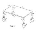
- FIG. 1is a diagrammatic view of a vehicle having a controllable suspension
- FIG. 2 ais a partially block diagram, partially diagrammatic representation of a controllable suspension according to the invention.
- FIG. 2 bis a partially block diagram, partially diagrammatic representation of a controllable suspension according to the invention.
- FIG. 2 cis a partially block diagram, partially diagrammatic representation of a controllable suspension
- FIG. 3is a diagrammatic view of the operation of a prior art active suspension
- FIGS. 4 a – 4 care diagrammatic views of the operation of an active suspension according to the invention.
- FIG. 5is a diagrammatic view of the operation of the operation of an active suspension according to the invention.
- FIGS. 6 a , 6 b , and 6 care flow diagrams illustrating the operation of a suspension system according to the invention.
- FIG. 7is a diagrammatic view illustrating a method of trajectory plan development
- FIG. 8is a diagram illustrating a method of collecting data in accordance with the invention.
- FIG. 9is a block diagram of a process for optimizing a trajectory plan
- FIGS. 10 a , 10 b , and 10 care diagrams of a vehicle operating on a road surface in accordance with the invention.
- FIGS. 11 a – 11 care diagrams illustrating the operation of a vehicle operating on a road surface in accordance with the invention.
- a suspension systemincludes surface engaging devices, such as wheels 14 connected to payload compartment 16 (represented diagrammatically as a plane) of the vehicle by a controllable suspension element 18 .
- the suspension systemmay include conventional suspension elements (not shown), such as a coil or leaf spring arrangement or damper. While one embodiment of the invention is an automobile, so that the surface engaging devices are wheels and the payload includes passengers, the invention may also be practiced in other types of vehicles, such as cargo carrying vehicles.
- Payload compartment 16may be a planar structure or may be enclosed on some or all sides.
- the surface engaging devicesmay include tracks or runners.
- the inventionmay also be practiced in vehicles that engage the surface through some form of levitation, such as magnetic or pneumatic levitation, so that the surface engaging devices include devices that do not require physical contact with the surface, and so that the surface may include tracks or open terrain.
- levitationsuch as magnetic or pneumatic levitation
- the inventionwill be described as embodied in an automobile.
- Controllable suspension elements 18may be one of a variety of suspension elements that receive, or are capable of being adapted to receive, control signals from a microprocessor and to respond to the signals.
- Controllable suspension elements 18may be components of a conventional active suspension system, in which the controllable suspension elements can respond to the control signals by varying the vertical displacement between the passenger compartment 16 and wheel 14 by applying a force. Suitable active suspension systems are described in U.S. Pat. Nos. 4,960,290 and 4,981,309 incorporated by reference herein.
- the forcemay be transmitted through some element such as a linear or rotary actuator, ball screw, pneumatic system, or hydraulic system, and may include intervening elements between the wheel and the force producing element.
- the controllable active suspensionmay also comprise an adaptive active vehicle suspension such as described in U.S. Pat. No. 5,432,700, in which signals may be used to modify adaptive parameters and gains.
- Controllable suspension elements 18may also be components of a conventional suspension system, which apply forces between passenger compartment 16 and wheel 14 reactively, in response to vertical forces resulting from wheel 14 passing over uneven surfaces.
- the controllable suspension elementsmay respond to the control signals by extending or compressing a spring, by changing a damping rate, or in other ways.
- the inventionwill be described in an embodiment in which the controllable suspension element is an active suspension element. Referring now to FIG. 2 a , there is shown a block diagram of a suspension according to the invention.
- Controllable suspension element 18is coupled to a microprocessor 20 which is in turn coupled to profile storage device 22 and optional locator system 24 .
- the suspension systemfurther includes sensors 11 , 13 , and 15 associated with payload compartment 16 , controllable suspension elements 18 , and wheels 14 , respectively. Sensors, 11 , 13 , and 15 are coupled to microprocessor 20 . Locator system 24 may receive signals from an external source, such as a positioning satellite 23 . For convenience, only one of the controllable suspension elements 18 is shown. The remaining wheels 14 , controllable suspension elements 18 , and the respective sensors 11 , 13 , and 15 are coupled to microprocessor 20 substantially as shown in FIG. 2 a.
- Microprocessor 20may be a single microprocessor as shown. Alternatively, the functions performed by microprocessor 20 may be performed by a number of microprocessors or equivalent devices, some of which can be located remotely from vehicle 10 , and may wirelessly communicate with components of the suspension system, which are located on vehicle 10 .
- Profile storage device 22may be any one of a number of types of writable memory storage, such as RAM, or mass storage devices such as a magnetic or writable optical disk. Profile storage device 22 may be included in the vehicle as shown, or may be at some remote location, with a broadcasting system for wirelessly communicating path profile data to the vehicle.
- Locator system 24may be one of a number of systems for providing longitudinal and latitudinal position, such as the Global Positioning System (GPS) or an inertial navigation system (INS). Locator system 24 may include systems, which provide for user input to indicate location and may also include profile matching systems that compare the profile of the path being driven by the vehicle with the profiles stored in memory storage.
- GPSGlobal Positioning System
- INSinertial navigation system
- the path being driven onis a roadway.
- the inventionmay be used in other types of vehicles that do not operate on roadways, such as open terrain vehicles and vehicles that operate on rails.
- the pathcan be typically defined by a location and a direction.
- the inventionwill be described as embodied in an automobile for operating on a roadway.
- a suspension system incorporating the inventionmay also include a trajectory planning subsystem, which includes (referring to FIG. 2 a ) microprocessor 20 , profile storage device 22 , and locator system 24 .
- Locator system 24detects the location of the vehicle, and microprocessor 20 retrieves a copy of the profile of the road, if available, from a plurality of profiles stored in profile storage device 22 .
- Microprocessor 20calculates or retrieves a trajectory plan responsive to the road profile, and issues control signals to controllable suspension element 18 to execute the trajectory plan.
- the profile retrieval, trajectory calculation, and suspension controlmay be performed by a single microprocessor as shown, or may be done by separate microprocessors if desired.
- the trajectory plan development processis described more fully in connection with FIGS. 6 a and 6 b . If controllable suspension element 18 is an active suspension acting reactively to road forces, microprocessor 20 may issue an adjusted control signal to controllable suspension element 18 based in part on the road profile.
- a road profileincludes a series of vertical (z-axis) deflections from a reference point.
- the z-axis deflection measurementsare typically taken at uniform distances from the location taken in the direction of travel.
- a road profilecan also contain additional data such as x-axis and y-axis deflection; compass heading; steering angle; or other information such as may be included in navigation systems, such as commercially available vehicle navigation products.
- the additional datamay involve greater processing capability of microprocessor 20 and profile storage device 22 , but may be advantageous in using “dead reckoning” or pattern matching techniques described below to more precisely locate the vehicle or in uniquely associating a road profile with a location. Additionally, the additional data may be advantageous in determining, for example, the degree to which traction should be considered in developing the trajectory.
- a trajectory planis a pre-determined path in space of a point or set of points on the payload compartment.
- the trajectorymay represent at least two points, respectively forward and rearward on the payload compartment.
- the trajectory planmay represent at least two points, one on each side of the vehicle. In a four wheeled vehicle, it may be convenient to use for trajectory plan development four points on the payload compartment, one near each wheel. Pairs of the points could be averaged (such as averaging the two points on each side of the vehicle to consider roll in the development of the trajectory plan, or averaging the two points in the front and the rear, respectively, to consider pitch in the development of the trajectory plan). For simplicity of explanation, the invention will be described in terms of a single point.
- the microprocessorissues control signals to controllable suspension element 18 to cause the vehicle to follow the trajectory plan. More detail on trajectory plans and the execution of trajectory plans are set forth in the examples that follow.
- the trajectory planmay take a number of factors into account, for example matching the pitch or roll of the vehicle to the pitch or roll expected by the passengers; minimizing the vertical acceleration of the payload compartment; maximizing the stroke of the suspension available to absorb bumps or dips, (hereinafter “disturbances”) in the road; minimizing the amplitude or occurrence of accelerations of an undesirable frequency, such as frequencies around 0.1 Hz, which tends to induce nausea; maximizing tire traction; or others.
- the trajectory planmay also include “anticipating” a disturbance in the road and reacting to it before it is encountered, as will be described below in the discussion of FIG. 5 . Further, particularly if the suspension system includes a conventional spring to support the weight of the car and the operation of the active suspension element extends or compresses the conventional spring, the trajectory plan may take power consumption into account.
- FIG. 2 bthere is shown another embodiment of the invention incorporating a trajectory plan storage device 25 .
- Elements of FIG. 2 bare similar to elements of FIG. 2 a , except profile device 22 of FIG. 2 a is replaced by a trajectory plan storage device 25 .
- Trajectory plan storage device 25may be any one of a number of types of writable memory storage, such as RAM, or mass storage devices such as a magnetic or writable optical disk.
- Trajectory plan storage device 25may be included in the vehicle as shown, or may be at some remote location, with a broadcasting system for wirelessly communicating path profile data to the vehicle.
- Operation of the embodiment of FIG. 2 bis similar to the operation of the embodiment of FIG. 2 a , except that microprocessor 20 retrieves and calculates trajectory plans that are associated with locations rather than being associated with profiles.
- FIG. 2 cAnother embodiment of the invention, shown in FIG. 2 c , includes both the profile storage device of FIG. 2 a and the trajectory plan storage device of FIG. 2 b .
- the storage devicesmay be separate devices or may be different portions of a single memory device. Operation of embodiments including trajectory plan storage device 25 are described further in the discussion of FIG. 6 c.
- FIG. 3shows an example of the operation of a conventional active suspension without a trajectory planning subsystem.
- front wheel 14 f ′encounters sloped section 41 , the distance between payload compartment 16 ′ and front wheel 14 f ′ is shortened.
- suspension element 18 f ′is “nosed in” to slope 41 , and in extreme cases may reach or approach a “bottomed out” condition, such that there is little or no suspension travel left to accommodate bumps in the rising surface.
- a “centered” positionis typically the condition of the suspension when there is no upward or downward force, other than the weight of the vehicle, on the suspension. The centered position is not necessarily a position at which there is equal suspension available for upward and downward disturbances.
- Microprocessor 20 of FIG. 2 afurnishes a computed trajectory plan 47 , which closely matches the road surface, including sloped section 41 , and issues appropriate control signals to controllable suspension elements 18 f and 18 r to follow the trajectory plan.
- the trajectory plancan be followed by exerting no force to shorten or lengthen the distance between wheels 14 f and 14 r and payload compartment 16 , or if the suspension system includes a conventional spring, the trajectory plan can be followed by exerting only enough force to counteract acceleration resulting from force exerted by the spring.
- FIGS. 4 a – 4 cillustrates the principle that following the trajectory plan may occur with little or no net force being applied by the controllable suspension element 18 and that execution of the trajectory planning subsystem may affect the normal operation of an active suspension.
- the vehicleis experiencing upward acceleration, and the normal reactionary operation of the active suspension would shorten the distance between wheel 14 f and the payload compartment 16 as shown in FIG. 3 .
- the active suspensionWith a suspension according to the invention, operating with a trajectory plan, the active suspension could remain in a centered position, so that the vehicle payload compartment follows trajectory plan 47 .
- the operational example of FIGS. 4 b – 4 ccould be combined with the operational example of FIG. 5 below so that the vehicle payload compartment follows trajectory plan 47 .
- FIG. 5shows another example of the operation of an active suspension with a trajectory planning subsystem.
- Road profile 50includes a large bump 52 .
- Microprocessor 20(of FIG. 2 a or 2 b ) furnishes a computed trajectory plan 54 appropriate for road profile 50 .
- controllable suspension element 18exerts a force to gradually lengthen the distance between wheel 14 and payload compartment 16 .
- the normal operation of the controllable suspension element 18causes controllable suspension element 18 to exert a force, which shortens the distance between payload compartment 16 and wheel 14 .
- controllable suspension element 18When wheel 14 reaches the crown 57 of bump 52 , controllable suspension element 18 begins to exert a force, which lengthens the distance between payload compartment 16 and wheel 14 . After wheel 14 has passed the end of bump 52 , controllable suspension element 18 exert a force shortening the distance between payload compartment 16 and wheel 14 .
- the example of FIG. 5illustrates the principle that the trajectory planning subsystem may cause the controllable suspension element 18 to exert a force to lengthen or shorten the distance between wheel 14 and payload compartment 16 even on a level road and further illustrates the principle that the trajectory plan may cause the controllable suspension element to react to a disturbance in the road before the disturbance is encountered.
- FIG. 5illustrates several advantages of a suspension system according to the invention.
- the vertical displacement of the payload compartmentis spread over a larger distance and over a longer period of time than if the suspension system reacted to bump 52 when the tire encountered bump 52 .
- the vertical displacement, vertical velocity and vertical acceleration of payload compartment 16are low, so passengers encounter less discomfort than with a suspension system without trajectory planning.
- the trajectory planning subsystemeffectively provides for large bump 52 , and the normal operation of the controllable suspension element is still available to handle disturbances that are not indicated in the road profile.
- the active suspension element in reactionary operating modeneed only react to the difference between the profile and the actual road surface.
- the active suspension systemneed only provide for the difference between the actual and the stored profile of bump 52 .
- the trajectory planmay take perceptual thresholds of vehicle occupants into account. For example, in FIG. 5 , even less vertical acceleration would be encountered by the occupants of the vehicle if the trajectory plan began rising before point 56 and returned the vehicle to the equilibrium position after point 58 . However, the difference in vertical acceleration may not be enough to be perceived by the vehicle occupants, so the active suspension need not react before point 56 or continue to react past point 58 . Additionally, if the vehicle includes a conventional suspension spring, the force applied by the active suspension between points 56 and 57 may need to exert a force to extend the spring in addition to a force to lift the vehicle, so not beginning the rise of the trajectory plan until point 56 may consume less power than beginning the rise earlier.
- sensors 11 , 13 , 15collect road profile information and transmit the information to microprocessor 20 which records the road profile in profile storage device 22 .
- the profile microprocessorcompares the road profile information with road profiles that have been previously stored in profile storage device 22 . The comparison may be accomplished using a pattern matching system as described below. If the road profile information matches a road profile that has previously been stored, at step 62 a , the profile is retrieved, and microprocessor 20 calculates a trajectory plan appropriate for that profile.
- sensors 11 , 13 , 15furnish signal representations of the road profile that may be used to modify, if necessary, the profile stored in profile storage device 22 .
- controllable suspension element 18acts in a reactionary mode.
- step 70locator system 24 determines the location and direction of the vehicle.
- trajectory plan microprocessor 20examines stored profiles in profile storage device 22 to see if there is a profile associated with that location. If there is a profile associated with that location, at step 74 a microprocessor 20 retrieves the profile and calculates or retrieves a trajectory plan. Depending on how the data is stored and processed, step 72 may also consider direction of travel in addition to location in determining whether there is an associated profile.
- sensors 11 , 13 , 15provide signals representative of the road profile that may be used to modify, if necessary, the profile stored in profile storage device 22 .
- a controllable suspension 18acts as a reactionary active suspension.
- sensors 11 , 13 , 15furnish signals representative of the road profile, which is stored in profile storage device 22 .
- FIG. 6 cthere is shown a method for developing, modifying, and executing a trajectory plan in an embodiment of the invention as shown in FIG. 2 b and having some device to locate the vehicle, such as the locator system 24 , or the profile storage device 22 of FIG. 2 a .
- locator system 24determines the location and direction of the vehicle.
- trajectory plan microprocessor 20examines trajectory plans in trajectory plan storage device 25 to see if there is a trajectory plan associated with that location. If there is a trajectory plan associated with that location, at step 174 a microprocessor 20 retrieves the trajectory plan and transmits the information to controllable suspension element 18 , which executes the trajectory plan.
- step 172may also consider direction of travel in addition to location in determining whether there is an associated profile.
- signals from sensors 11 , 13 , 15 representative of the actual profilemay be recorded so that the trajectory plan associated with the location can later be modified to provide a smoother or more comfortable ride.
- a controllable suspension 18acts as a reactionary active suspension.
- signals representative of the trajectory resulting from the reactionary operation of the controllable suspension 18are recorded as the trajectory plan so that the stored trajectory plan can be modified to provide a smoother or more comfortable ride.
- the trajectory planmay be stored in a variety of forms, as will be described below in the discussion of FIG. 8 . Additionally, if the trajectory plan is calculated using characteristics (such as filter break points or window widths as will be described below), the characteristic may be stored, and the trajectory plan calculated “on the fly.” This method allows the system to operate with less storage, but requires more computational power.
- characteristicssuch as filter break points or window widths as will be described below
- FIGS. 6 a , 6 b , and 6 cillustrate one of the learning features of the invention.
- the profile or trajectory plan, or bothmay be modified, so that the trajectory plan furnished by microprocessor 20 may be used to provide for a smoother ride for the occupants of the vehicle during subsequent rides over the same portion of road.
- the vehicle suspension systemmay employ an optimization process shown below in FIG. 9 .
- locator system 24 of FIG. 2 aincorporating a high precision GPS system, such as a differential system accurate to within centimeters.
- Another methodis to include in locator system 24 of FIG. 2 a a GPS system having a lower degree of precision (such as a non-differential system accurate to within about 50 meters or some other locator system not incorporating GPS) and a supplementary pattern matching system.
- One pattern matching systemincludes a search for a known sequence of data in a target string of data.
- One method of pattern matching particularly useful for data that increases and decreases from a base pointincludes multiplying a known sequence of n numbers by strings of corresponding length in a target string. The n products are then summed, and when the sum peaks, there is a high degree of match. Other methods of pattern matching (with other methods of determining a high degree of match) may be used.
- Pattern matchingcan be usefully applied to a trajectory planning active suspension by recording a pattern of z-axis deflections from a base point and using the pattern of z-axis deflections as the search string.
- Pattern matchingcan then be used in at least two ways. In one application, the GPS system is used to get an approximate (within 30 meters) location of the vehicle, and pattern matching is then used to locate the vehicle more precisely, by using for the target string, the previously recorded pattern of z-axis deflections stored in profile storage device 22 of FIG. 2 a . In a second application, pattern matching is used to compare the pattern of z-axis deflections as measured by sensors 11 , 13 , and 15 of FIG. 2 a with patterns of z-axis deflections stored in profile storage device 22 to determine if there is a profile stored in memory.
- a “dead reckoning” systemmay also be used.
- a vehicle change in locationis estimated by keeping track of the distance the vehicle travels and the direction the vehicle travels. When the vehicle has been located precisely, the distance the vehicle travels may be tracked by counting wheel rotations, and the direction of travel may be tracked by recording the wheel angle or steering angle.
- a dead reckoning systemis very useful if GPS readings are difficult (such as if there are nearby tall buildings) and also reduces the frequency at which GPS readings need be taken.
- FIG. 7there is shown a diagrammatic view of an automobile and a road surface, illustrating the development of a trajectory plan.
- Line 80represents the road profile as stored by profile device 22 of FIG. 2 a .
- Line 82represents the road profile 80 which has been bidirectionally low-pass filtered using a break frequency in the range of 1 Hz, and is used as the trajectory plan; the bidirectional filtering eliminates phase lag inaccuracies that may be present with single directional filtering.
- controllable suspension element 18 of FIG. 2 aurges the payload compartment of automobile 84 to follow the trajectory plan represented by line 82 .
- the high frequency, low amplitude disturbances in the roadare easily handled by the normal operation of the active suspension. Developing of a trajectory plan by low pass filtering is very useful in dealing with the situation as described in FIGS. 3 and 4 a – 4 c.
- Processing the road profile data in the time domain to develop trajectory plansis advantageous when the velocity of the vehicle is constant; that is, each trip across the road segment is at the same velocity.
- processing the data in the spatial domainmay be more useful than processing the data in the time domain. It may be more convenient to store data in spatial form, and processing the data in the spatial domain may make it unnecessary to transform the data to temporal form. Additionally, processing the data in the spatial domain allows the trajectory plan to be calculated including velocity as a variable; that is, the trajectory plan may vary, depending on the velocity. If the data is processed in the spatial domain, it may be advisable to perform some amount of time domain translation, for example to minimize acceleration at objectionable frequencies, such as the 0.1 Hz “seasick” frequency.
- Trajectory plan developmentmay take into account factors in addition to the spatial or time domain filtered road profile.
- the trajectory planmay take into account large disturbances in the road as shown in FIG. 5 , and discussed in the corresponding portion of the disclosure.
- FIG. 8there is shown a method of collecting data points that facilitates processing the data in either the time domain or the spatial domain.
- FIG. 8also shows a method of converting data from the time domain to the spatial domain.
- Data from sensors 11 , 13 , 15are collected at time interval ⁇ t 92 .
- a typical range of values for ⁇ tis 0.1 ms (equivalent to a 10 kHz sampling rate) to 1 ms. (equivalent to a 1 kHz sampling rate).
- the data points taken during the interval 94 in which the vehicle has traveled distance ⁇ xare combined and averaged. The averaged data is then used as data for determining a road profile and used to calculate a trajectory plan.
- Typical values for ⁇ xare four to eight inches (10.2 to 20.3 cm); ⁇ x intervals may be measured by sensors in the vehicle drive train, which may also provide readings for the vehicle speedometer and odometer. The number n of time intervals ⁇ t 92 taken during the interval in which the vehicle has traveled distance ⁇ x varies with the velocity of the vehicle.
- the averaged data pointsare processed to determine a profile consisting of z-axis deflections relative to time (that is, a time domain representation of the profile). Since the data from sensors 11 , 13 , 15 may represent suspension displacement, velocity, or acceleration; the processing may include mathematical manipulation of some of the data to obtain z-axis deflections.
- the time domain representation of the profileis converted to a spatial domain profile consisting of z-axis deflections relative to a spatial measure (such as distance traveled) or to a position in space by processing the time domain data points by the distance traveled or by the velocity from a reference location.
- a profile consisting of z-axis deflections relative to distance traveledcan also be developed by collecting data in the spatial domain directly, at spatial intervals of ⁇ x′ 96 (which if desired may further include averaging data points taken over larger spatial interval ⁇ x 94 , including m intervals of distance ⁇ x′).
- a road profile that is expressed in the spatial domainis independent of the velocity of the vehicle.
- Representing the profile in the spatial domainmay be desirable if the profile is supplemented by location information determined by GPS systems, inertial navigation systems, pattern matching, or dead reckoning, or other methods using spatial terms; if there exists a database of profiles corresponding to the location, and if the corresponding profiles are expressed in spatial terms; or if the section of road is traveled over at widely varying velocities.
- the profilemay be recorded as a series of data points representing states of the vehicle, which are measured by sensors 11 , 13 , and 15 .
- data from some or all of the sensors 11 , 13 , 15are stored in their native dimensions (that is, forces, accelerations and velocities are stored, respectively, as forces, accelerations and velocities, and are not converted to other units of measure, such as vertical deflection).
- the datamay be averaged over time or distance, as described above. This implementation is especially useful for use with pattern matching systems, which are described above.
- pattern matchingis performed by comparing the state of the vehicle as measured by sensors 11 , 13 , and 15 with recorded profiles (expressed as vehicle states) to determine the degree of match. Recording the profile as a series of data points also lends itself to including in the profile data, in addition to states of the vehicle measured by sensors 11 , 13 , and 15 , additional data. Additional data may include lateral acceleration, velocity, or suspension displacement, compass heading, steering angle, or other data such as may be included in commercially available navigation systems. The additional data may be used to provide more precise pattern matching.
- One method of developing a trajectory planis to smooth the data representing the profile in a manner that provides positive and negative values.
- One method of smoothingis to low pass filter, preferably bi-directionally, the profile data.
- the filteris a spatial filter; in one implementation the spatial filter is a real low-pass filter having a fixed break point on the order of 15 to 30 feet (4.6 to 9.1 meters).
- filteringcan be accomplished in either the time or frequency domains (temporal data can be transformed to the frequency domain through use of a Fourier transform).
- the filterscould be real or complex filters of various orders or dimensions.
- the trajectory plancan be developed using multiple passes in each direction of the filter.
- While low-pass filtering of the temporal or spatial datais one method of developing a trajectory plan, other methods of smoothing profile data may be used to develop a trajectory plan.
- Other forms of data smoothinginclude anti-causal and non-linear filtering, averaging, windowed averaging, and others.
- the datais expressed in positive and negative terms; for example a bump may be treated as a positive value and a depression (or “pothole”) treated as a negative value.
- the data smoothingmaintains positive and negative values. Maintaining positive and negative values in the data enables the trajectory plan to urge the controllable suspension element to apply a force in either direction, for example, to shorten the distance between the wheel and the passenger compartment in the case of a bump and to lengthen the distance between the wheel and the passenger compartment in the case of a depression. Maintaining positive and negative data values is not required for active suspension systems that modify controller parameters such as gain, and therefore expressing the data in a form that is always positive, such as root-mean-square, is sufficient.
- Active suspension systemsthat control gain control how the suspension will exert a force to shorten or lengthen the distance between the wheel and the passenger compartment responsive to a road disturbance only when the road disturbance is encountered; whether the disturbance is positive or negative can be determined when the disturbance is encountered.
- An active suspension system according to the inventionexerts a force to lengthen or shorten the distance between the wheel and the passenger compartment before the disturbance is encountered; therefore it is desirable that data for a suspension system according to the invention retain positive and negative values.
- a filter used to develop the trajectory planmay have either a fixed break point or a variable break point.
- FIG. 9shows a method for optimizing a trajectory plan.
- a profileis determined, either by passing over the road, or by retrieving a profile from a database.
- a trajectory planis developed.
- the measure(s) of performanceis compared with the measures of any previous trajectory plans that may have been calculated for that profile, and the characteristic corresponding with the better performance according to the performance measures is retained.
- “better performance”may be either a higher or lower value of the performance measure.
- the performance measureis measure (for example of power consumption, vertical velocity, vertical acceleration) in which a lower value is “better performance.”
- the specific trajectory plan characteristic value or values that can be modifieddepends on the method that was used to develop the trajectory plan. For example, if the trajectory plan was developed by low pass filtering the profile data, the break point of the filter may be the characteristic value that is modified; if the trajectory plan was developed using windowed averaging, the size of the window may be the characteristic value that is modified.
- the trajectory plansare developed by smoothing the profile data, using a low pass filter.
- the first trajectory planmay be developed using an initial seed value for the break frequency of the low pass filter.
- the initial seed valuemay be selected based on the smoothness of the road, using a longer (or lower frequency) break point if the road is smooth, and a shorter (or higher frequency) break point if the road is rough.
- Subsequent trajectory plansare developed using filters having different break points (in either the spatial or temporal domains). An adequately optimized condition may exist if neither an increase nor a decrease of the filter break point results in a better measure or measures of performance or if some pre-determined threshold of performance is reached.
- the process described aboveis consistent with the concept of finding a local maximum in system performance.
- Known optimization techniquescan be applied that may allow the system to find a global performance maximum. For example, if only a single characteristic is varied, the characteristic may be varied over the entire range of possible values for the characteristic and performance calculated for each value.
- more sophisticated gradient-based search algorithmscan be applied to improve the speed with which an optimum condition can be found.
- Gradient based methodscan also be used to find optimum performance (local or global) when more than one characteristic at a time is allowed to vary.
- the process of FIG. 9may be modified in a number of ways.
- the length of road section to which the process of FIG. 9 is appliedmay be varied.
- the process of FIG. 9may be executed by a computer remote from the vehicle and downloaded to the vehicle.
- the process of FIG. 9may be executed by a microprocessor onboard the vehicle.
- a single characteristicmay be varied over a limited range of values and the characteristic corresponding to the best measure of performance retained.
- the processmay be performed when the computational capacity of the vehicle is not being used, such as when the vehicle is parked.
- Executions of the trajectory planmay be either actual passes of the vehicle over the stretch of road, or may be simulated, at a convenient time, such as when the car is parked or not moving.
- a trajectory planis a pre-determined path in space of a point or set of points on the payload compartment.
- the trajectory planmay be stored in spatial terms, or may be stored as a succession of forces to be applied by controllable suspension element 18 between payload compartment 16 and wheel 14 to cause a point, such as a point in the passenger compartment, to follow the trajectory prescribed by the trajectory plan.
- the trajectory planmay also be stored as a succession of vehicle states that would be measured by sensors 11 , 13 , 15 if the trajectory plan were executed, or as a set of commands to the controllable suspension.
- Calculating and storing the trajectory plan in terms of force applied or in terms of vehicle statessimplifies the calculation of the trajectory plan by eliminating mathematical manipulation of data to get the data in the proper unit of measure. For example, if the trajectory plan is expressed in terms of forces to be applied by the controllable suspension, the profile data can be low-pass filtered to obtain a trajectory plan that is also expressed in terms of forces to be applied by the controllable suspension. The need for converting the data from force to acceleration to velocity to displacement is eliminated.
- FIGS. 3 , 4 a – 4 c , and 5 and the corresponding portions of the disclosureillustrated the principle that the execution of the trajectory planning subsystem may affect the normal reactionary operation of an active suspension.
- a normal reactionary operation of the suspension elementmay cause the vehicle to “nose in” to a hill.
- the controllable suspension using a trajectory plancauses the vehicle to follow a pre-determined path in space (that is, the trajectory plan) and pitch, rather than “nosing in” to a hill.
- the trajectory planmay cause the controllable suspension to exert no force even if there is a road disturbance.
- the trajectory planmay cause the controllable suspension to exert a force related to a road disturbance before encountering the disturbance.
- the trajectory planmay cause the controllable suspension to continue to exert a force related to a road disturbance even after the disturbance has been traversed.
- FIGS. 10 a – 10 ceach show diagrammatic views of a vehicle and a road surface, illustrating the application of the invention to the front and rear wheels.
- the “front to rear” featureis especially useful when a vehicle is traversing a portion of road for the first time, and for which no road profile is available.
- the vehicles of FIGS. 10 a and 10 buse information from sensors associated with a front wheel to develop a trajectory plan for the rear wheel. This feature of the invention is illustrated by showing the trajectory of a point 114 in the passenger compartment above a front wheel 14 f , and the trajectory of a point 116 in the passenger compartment above a rear wheel 14 r .
- Front and rear wheels 14 f and 14 rare mechanically coupled to payload compartment 16 by corresponding controllable suspension elements 18 f and 18 r , respectively.
- the vehicleis operating on a road that has a disturbance 112 a that has a height h 1 , which is greater than the available suspension stroke with the suspension in a centered position, and which is smaller than total combined suspension stroke (that is the combined available upwards and downwards suspension travel with the suspension element in a centered position).
- the suspensionreacts to keep the trajectory of point 114 flat.
- the microprocessormay record the profile of the road and smooth the profile data to provide a trajectory plan for execution by the rear wheel controllable suspension element 18 r .
- controllable suspension element 18 rexerts a force to lengthen the distance between wheel 14 r and passenger compartment 16 , urging point 116 gradually upward.
- wheel 14 fengages disturbance 112 a
- the normal reactionary mode action of the controllable suspension element 18 ris to exert a force to cause point 116 to follow the trajectory plan 124 .
- controllable suspension elementSince the controllable suspension element has lengthened the distance between the wheel and the passenger compartment, more suspension stroke is available, and the controllable suspension element can absorb disturbance 112 a without reaching or approaching a bottomed out situation.
- a trajectory such as trajectory 124is more comfortable for passengers in the vehicle because it avoids rapid vertical accelerations and velocities.
- FIG. 10 bAnother feature of the invention is illustrated in FIG. 10 b .
- a vehicle similar to the vehicle of FIG. 10 ahas a centering system for maintaining available suspension stroke and preventing the suspension element from bottoming out. If the suspension element approaches a bottomed out or topped out condition, the centering system urges the suspension element system toward a centered position, which preserves suspension travel but allows some vertical acceleration of the passenger compartment.
- Road disturbance 112 bhas a height h2 that is slightly less than the available suspension stroke with the suspension element in a centered position.
- the controllable suspension element 18 facts to keep the passenger compartment level and to prevent vertical acceleration of the passenger compartment.
- the centering systemacts to prevent the suspension element from bottoming out by allowing some vertical movement of the passenger compartment as indicated at point 126 of path 128 .
- the sensorsrecord the height h2 of the disturbance. Since the height of the disturbance 112 b is less than the available suspension travel, the controllable suspension disables the centering system for the rear wheel.
- the rear wheel 14 rtraverses the disturbance 112 b , there is no vertical movement of the passenger compartment, as indicated by path 130 .
- FIG. 10 cA variation of the example of FIG. 10 b is shown in FIG. 10 c .
- the rear control suspension elementexerts a force so that the path of 130 of rear point 116 follows the same trajectory as the front point 114 . This lessens the amount of pitch experienced by the passengers.
- the rear suspension elementmay operate as in FIG. 10 b.
- FIGS. 11 a and 11 bthere is shown another feature of the invention.
- front controllable suspension element 18 facts to keep the passenger compartment level.
- the leveling action of the front controllable suspension elementcontinues until point 132 in which the front controllable suspension element 18 f is “nosed in” and approaches bottoming out as discussed above in the discussion of FIG. 3 .
- a centering subsystemurges the front controllable suspension element 18 f toward a centered position, at, for example, point 134 .
- the occupants of the vehicleparticularly the front seat passengers experience a “nosed in” sensation, and experience the upward acceleration after the wheel has encountered the hill, that is after they expect it. This can be disconcerting to the occupants.
- the passengersexperience vertical acceleration that is greater than the passengers would have experienced if the front suspension element had remained in a centered position and not acted to keep the car level.
- the vertical acceleration, suspension displacement, and other measurementsare recorded by the microprocessor, which then develops a response for the rear suspension element.
- the microprocessorissues a command to the rear suspension element to remain in a centered position and not to react to the upslope.
- the resultis that the rear point 116 follows a path that is similar to the upslope of the road, and which causes the occupants of the vehicle, especially the occupants of the back seat, to experience less vertical acceleration and velocity when the rear wheel encounters the upslope than when the front wheel encounters the upslope. Additionally, they experience the amount of upward acceleration that they expect, and experience the upward acceleration when they expect it.
- FIGS. 11 a and 11 billustrates the feature that a controllable suspension according to the invention may react to some road stimuli less than a conventional reactive suspension.
- the operational example of FIG. 11 bmay be combined with the operational example of FIG. 10 a to lessen the upward acceleration at point 136 of FIG. 11 a – 11 b so that the actual trajectory spread the upward acceleration over a longer horizontal distance, such as in trajectory 130 A of FIG. 11 c.
- Vehicle suspension systems not using information from a front suspension element to affect the operation of a rear wheel suspension elementcannot perform the ride-improving actions shown in FIGS. 10 a , 10 b , and 11 b .
- Vehicle suspensions that use information from a front suspension element to change characteristics of a control system of a rear suspension elementcannot cause the rear suspension element to apply a force before a disturbance is encountered.
Landscapes
- Engineering & Computer Science (AREA)
- Radar, Positioning & Navigation (AREA)
- Remote Sensing (AREA)
- Mechanical Engineering (AREA)
- Automation & Control Theory (AREA)
- Physics & Mathematics (AREA)
- General Physics & Mathematics (AREA)
- Multimedia (AREA)
- Vehicle Body Suspensions (AREA)
Abstract
Description
Claims (14)
Priority Applications (16)
| Application Number | Priority Date | Filing Date | Title |
|---|---|---|---|
| US10/629,243US7195250B2 (en) | 2000-03-27 | 2003-07-28 | Surface vehicle vertical trajectory planning |
| JP2004034527AJP2004249976A (en) | 2003-02-18 | 2004-02-12 | Surface vehicle vertical trajectory planning |
| EP11160772.7AEP2351658A3 (en) | 2003-02-18 | 2004-02-17 | Surface vehicle suspension and operation |
| EP04100619.8AEP1449688B1 (en) | 2003-02-18 | 2004-02-17 | Surface vehicle vertical trajectory planning |
| CN2008100811754ACN101239572B (en) | 2003-02-18 | 2004-02-18 | Surface vehicle vertical trajectory planning |
| CN2008100811735ACN101239575B (en) | 2003-02-18 | 2004-02-18 | Surface vehicle vertical trajectory planning |
| CNA2004100054188ACN1524719A (en) | 2003-02-18 | 2004-02-18 | Vertical trajectory design for land vehicles |
| CN200810081174XACN101239571B (en) | 2003-02-18 | 2004-02-18 | Surface vehicle vertical trajectory planning |
| US11/608,622US7434816B2 (en) | 2000-03-27 | 2006-12-08 | Surface vehicle vertical trajectory planning |
| US11/670,849US7878510B2 (en) | 2000-03-27 | 2007-02-02 | Surface vehicle vertical trajectory planning |
| HK08112558.1AHK1118768B (en) | 2003-02-18 | 2008-11-17 | Surface vehicle vertical trajectory planning |
| HK08112559.0AHK1118769B (en) | 2003-02-18 | 2008-11-17 | Surface vehicle vertical trajectory planning |
| HK08112560.7AHK1118770B (en) | 2003-02-18 | 2008-11-17 | Surface vehicle vertical trajectory planning |
| US12/974,190US8517395B2 (en) | 2000-03-27 | 2010-12-21 | Surface vehicle vertical trajectory planning |
| US13/922,456US8948968B2 (en) | 2000-03-27 | 2013-06-20 | Surface vehicle vertical trajectory planning |
| US14/543,002US9417075B2 (en) | 2000-03-27 | 2014-11-17 | Surface vehicle vertical trajectory planning |
Applications Claiming Priority (3)
| Application Number | Priority Date | Filing Date | Title |
|---|---|---|---|
| US53584900A | 2000-03-27 | 2000-03-27 | |
| US10/368,187US20040046335A1 (en) | 2000-03-27 | 2003-02-18 | Surface vehicle vertical trajectory planning |
| US10/629,243US7195250B2 (en) | 2000-03-27 | 2003-07-28 | Surface vehicle vertical trajectory planning |
Related Parent Applications (2)
| Application Number | Title | Priority Date | Filing Date |
|---|---|---|---|
| US53584900AContinuation-In-Part | 2000-03-27 | 2000-03-27 | |
| US10/368,187Continuation-In-PartUS20040046335A1 (en) | 2000-03-27 | 2003-02-18 | Surface vehicle vertical trajectory planning |
Related Child Applications (2)
| Application Number | Title | Priority Date | Filing Date |
|---|---|---|---|
| US11/608,622ContinuationUS7434816B2 (en) | 2000-03-27 | 2006-12-08 | Surface vehicle vertical trajectory planning |
| US11/670,849ContinuationUS7878510B2 (en) | 2000-03-27 | 2007-02-02 | Surface vehicle vertical trajectory planning |
Publications (2)
| Publication Number | Publication Date |
|---|---|
| US20040251643A1 US20040251643A1 (en) | 2004-12-16 |
| US7195250B2true US7195250B2 (en) | 2007-03-27 |
Family
ID=32737990
Family Applications (6)
| Application Number | Title | Priority Date | Filing Date |
|---|---|---|---|
| US10/629,243Expired - LifetimeUS7195250B2 (en) | 2000-03-27 | 2003-07-28 | Surface vehicle vertical trajectory planning |
| US11/608,622Expired - Fee RelatedUS7434816B2 (en) | 2000-03-27 | 2006-12-08 | Surface vehicle vertical trajectory planning |
| US11/670,849Expired - Fee RelatedUS7878510B2 (en) | 2000-03-27 | 2007-02-02 | Surface vehicle vertical trajectory planning |
| US12/974,190Expired - Fee RelatedUS8517395B2 (en) | 2000-03-27 | 2010-12-21 | Surface vehicle vertical trajectory planning |
| US13/922,456Expired - Fee RelatedUS8948968B2 (en) | 2000-03-27 | 2013-06-20 | Surface vehicle vertical trajectory planning |
| US14/543,002Expired - Fee RelatedUS9417075B2 (en) | 2000-03-27 | 2014-11-17 | Surface vehicle vertical trajectory planning |
Family Applications After (5)
| Application Number | Title | Priority Date | Filing Date |
|---|---|---|---|
| US11/608,622Expired - Fee RelatedUS7434816B2 (en) | 2000-03-27 | 2006-12-08 | Surface vehicle vertical trajectory planning |
| US11/670,849Expired - Fee RelatedUS7878510B2 (en) | 2000-03-27 | 2007-02-02 | Surface vehicle vertical trajectory planning |
| US12/974,190Expired - Fee RelatedUS8517395B2 (en) | 2000-03-27 | 2010-12-21 | Surface vehicle vertical trajectory planning |
| US13/922,456Expired - Fee RelatedUS8948968B2 (en) | 2000-03-27 | 2013-06-20 | Surface vehicle vertical trajectory planning |
| US14/543,002Expired - Fee RelatedUS9417075B2 (en) | 2000-03-27 | 2014-11-17 | Surface vehicle vertical trajectory planning |
Country Status (4)
| Country | Link |
|---|---|
| US (6) | US7195250B2 (en) |
| EP (2) | EP1449688B1 (en) |
| JP (1) | JP2004249976A (en) |
| CN (1) | CN1524719A (en) |
Cited By (43)
| Publication number | Priority date | Publication date | Assignee | Title |
|---|---|---|---|---|
| US20050285356A1 (en)* | 2004-06-04 | 2005-12-29 | Malit Romeo F | Apparatus and method for set and forget driveby itself and or assisted any wheeled transportations and marking pavements of embedded data (peaks/valleys) by "reading" and "writing"; a systems for reading/writing vibrations of the road surfaces upon body of vehicles by sensors, printing cement/asphalt and processes for making same |
| US20060173596A1 (en)* | 2005-01-28 | 2006-08-03 | Hohmann Michael F | Automated vehicle suspension system |
| US20060224286A1 (en)* | 2005-03-30 | 2006-10-05 | Honda Motor Co., Ltd. | Control system for adjustable damping force damper |
| US20070168092A1 (en)* | 2000-03-27 | 2007-07-19 | Bose Corporation, A Delaware Corporation | Surface vehicle vertical trajectory planning |
| US20100217455A1 (en)* | 2007-09-13 | 2010-08-26 | Continental Teves Ag & Co. Ohg | Establishing quality parameters of a digital map |
| US20110186360A1 (en)* | 2005-08-29 | 2011-08-04 | Mobile Intelligence Corporation | Jumping for Reaching Denied Terrain |
| WO2014004119A1 (en) | 2012-06-27 | 2014-01-03 | Bose Corporation | Active wheel damping |
| WO2014004118A1 (en) | 2012-06-27 | 2014-01-03 | Bose Corporation | Anti-causal vehicle suspension |
| US9174508B2 (en) | 2013-03-15 | 2015-11-03 | Levant Power Corporation | Active vehicle suspension |
| US9260011B2 (en) | 2008-04-17 | 2016-02-16 | Levant Power Corporation | Hydraulic energy transfer |
| US9440508B2 (en) | 2014-11-25 | 2016-09-13 | Seth M. LACHICA | Active vehicle suspension system and method for managing drive energy |
| US9440507B2 (en) | 2013-03-15 | 2016-09-13 | Levant Power Corporation | Context aware active suspension control system |
| US9643467B2 (en) | 2014-11-10 | 2017-05-09 | Bose Corporation | Variable tracking active suspension system |
| US9689382B2 (en) | 2010-06-16 | 2017-06-27 | ClearMotion, Inc. | Integrated energy generating damper |
| US9694639B2 (en) | 2013-03-15 | 2017-07-04 | ClearMotion, Inc. | Distributed active suspension control system |
| US9702349B2 (en) | 2013-03-15 | 2017-07-11 | ClearMotion, Inc. | Active vehicle suspension system |
| US9702424B2 (en) | 2014-10-06 | 2017-07-11 | ClearMotion, Inc. | Hydraulic damper, hydraulic bump-stop and diverter valve |
| WO2017151720A1 (en) | 2016-03-02 | 2017-09-08 | Bose Corporation | Vehicle plant active suspension control based on vehicle position |
| US9855814B2 (en) | 2013-04-23 | 2018-01-02 | ClearMotion, Inc. | Active suspension with structural actuator |
| US10384871B2 (en)* | 2017-03-19 | 2019-08-20 | Gal Zuckerman | Next generation on-road vehicles and related methods of usage |
| US20190322204A1 (en)* | 2017-03-19 | 2019-10-24 | Gal Zuckerman | Systems and methods for autonomously altering shape and functionality of on-road vehicles |
| US10814690B1 (en) | 2017-04-18 | 2020-10-27 | Apple Inc. | Active suspension system with energy storage device |
| CN112092562A (en)* | 2019-06-18 | 2020-12-18 | 奥迪股份公司 | Controlled pitch tilt of vehicle |
| US10899340B1 (en) | 2017-06-21 | 2021-01-26 | Apple Inc. | Vehicle with automated subsystems |
| US10906370B1 (en) | 2017-09-15 | 2021-02-02 | Apple Inc. | Active suspension system |
| US10960723B1 (en) | 2017-09-26 | 2021-03-30 | Apple Inc. | Wheel-mounted suspension actuators |
| US11046143B1 (en) | 2015-03-18 | 2021-06-29 | Apple Inc. | Fully-actuated suspension system |
| US20210256467A1 (en)* | 2017-03-19 | 2021-08-19 | Gal Zuckerman | Systems and methods for autonomously delivering consumer items in disposable packages |
| US11124035B1 (en) | 2017-09-25 | 2021-09-21 | Apple Inc. | Multi-stage active suspension actuator |
| US11173766B1 (en) | 2017-09-07 | 2021-11-16 | Apple Inc. | Suspension system with locking structure |
| US11179991B1 (en) | 2019-09-23 | 2021-11-23 | Apple Inc. | Suspension systems |
| US11285773B1 (en) | 2018-09-12 | 2022-03-29 | Apple Inc. | Control system |
| US11345209B1 (en) | 2019-06-03 | 2022-05-31 | Apple Inc. | Suspension systems |
| US11358431B2 (en) | 2017-05-08 | 2022-06-14 | Apple Inc. | Active suspension system |
| US11634167B1 (en) | 2018-09-14 | 2023-04-25 | Apple Inc. | Transmitting axial and rotational movement to a hub |
| US20230192143A1 (en)* | 2017-03-19 | 2023-06-22 | Gal Zuckerman | Systems And Methods For Autonomously Delivering Packages Using A Plurality Of Package Containers |
| US11707961B1 (en) | 2020-04-28 | 2023-07-25 | Apple Inc. | Actuator with reinforcing structure for torsion resistance |
| US11828339B1 (en) | 2020-07-07 | 2023-11-28 | Apple Inc. | Vibration control system |
| US11932072B2 (en) | 2021-03-08 | 2024-03-19 | DRiV Automotive Inc. | Suspension control system and method with event detection based on unsprung mass acceleration data and pre-emptive road data |
| US11938922B1 (en) | 2019-09-23 | 2024-03-26 | Apple Inc. | Motion control system |
| US12017498B2 (en) | 2021-06-07 | 2024-06-25 | Apple Inc. | Mass damper system |
| US12168375B1 (en) | 2023-01-26 | 2024-12-17 | Apple Inc. | Motion control system |
| US12251973B2 (en) | 2022-06-10 | 2025-03-18 | Apple Inc. | Vibration absorber |
Families Citing this family (93)
| Publication number | Priority date | Publication date | Assignee | Title |
|---|---|---|---|---|
| US20050242052A1 (en)* | 2004-04-30 | 2005-11-03 | O'connor Michael L | Method and apparatus for gantry crane sway determination and positioning |
| JP4514520B2 (en)* | 2004-06-02 | 2010-07-28 | 株式会社日立製作所 | Adaptive vehicle travel control system and adaptive vehicle travel control method |
| JP4525918B2 (en) | 2005-04-15 | 2010-08-18 | トヨタ自動車株式会社 | Damping force generating system and vehicle suspension system including the same |
| JP4852919B2 (en)* | 2005-07-25 | 2012-01-11 | アイシン・エィ・ダブリュ株式会社 | Vehicle ride control system and vehicle ride control method |
| US20070208484A1 (en)* | 2006-03-06 | 2007-09-06 | Denso Corporation | Vehicle cruise control system and road condition estimating system |
| DE102006039353A1 (en)* | 2006-08-22 | 2008-03-06 | Daimler Ag | Device and method for influencing the spring force characteristic of an active chassis of a motor vehicle |
| JP4539694B2 (en)* | 2007-08-28 | 2010-09-08 | トヨタ自動車株式会社 | Vehicle height adjustment device |
| US20090164063A1 (en)* | 2007-12-20 | 2009-06-25 | International Business Machines Corporation | Vehicle-mounted tool for monitoring road surface defects |
| US8451140B2 (en)* | 2007-12-20 | 2013-05-28 | International Business Machines Corporation | Monitoring road surface conditions |
| US9033122B2 (en) | 2009-01-07 | 2015-05-19 | Fox Factory, Inc. | Method and apparatus for an adjustable damper |
| US10047817B2 (en) | 2009-01-07 | 2018-08-14 | Fox Factory, Inc. | Method and apparatus for an adjustable damper |
| US8627932B2 (en) | 2009-01-07 | 2014-01-14 | Fox Factory, Inc. | Bypass for a suspension damper |
| US20100170760A1 (en) | 2009-01-07 | 2010-07-08 | John Marking | Remotely Operated Bypass for a Suspension Damper |
| US20120305350A1 (en) | 2011-05-31 | 2012-12-06 | Ericksen Everet O | Methods and apparatus for position sensitive suspension damping |
| US10060499B2 (en) | 2009-01-07 | 2018-08-28 | Fox Factory, Inc. | Method and apparatus for an adjustable damper |
| US9452654B2 (en) | 2009-01-07 | 2016-09-27 | Fox Factory, Inc. | Method and apparatus for an adjustable damper |
| US11306798B2 (en) | 2008-05-09 | 2022-04-19 | Fox Factory, Inc. | Position sensitive suspension damping with an active valve |
| US8393446B2 (en) | 2008-08-25 | 2013-03-12 | David M Haugen | Methods and apparatus for suspension lock out and signal generation |
| US9140325B2 (en) | 2009-03-19 | 2015-09-22 | Fox Factory, Inc. | Methods and apparatus for selective spring pre-load adjustment |
| EP3666347B1 (en) | 2008-11-25 | 2021-10-20 | Fox Factory, Inc. | Computer usable storage medium for virtual competition |
| US10036443B2 (en) | 2009-03-19 | 2018-07-31 | Fox Factory, Inc. | Methods and apparatus for suspension adjustment |
| US9422018B2 (en) | 2008-11-25 | 2016-08-23 | Fox Factory, Inc. | Seat post |
| US8185269B2 (en)* | 2008-12-16 | 2012-05-22 | GM Global Technology Operations LLC | Active suspension system for a vehicle and method of operating the same |
| US10821795B2 (en) | 2009-01-07 | 2020-11-03 | Fox Factory, Inc. | Method and apparatus for an adjustable damper |
| US9038791B2 (en) | 2009-01-07 | 2015-05-26 | Fox Factory, Inc. | Compression isolator for a suspension damper |
| US12122205B2 (en) | 2009-01-07 | 2024-10-22 | Fox Factory, Inc. | Active valve for an internal bypass |
| US11299233B2 (en) | 2009-01-07 | 2022-04-12 | Fox Factory, Inc. | Method and apparatus for an adjustable damper |
| US8936139B2 (en) | 2009-03-19 | 2015-01-20 | Fox Factory, Inc. | Methods and apparatus for suspension adjustment |
| EP3543045B1 (en)* | 2009-05-04 | 2021-06-16 | Fox Factory, Inc. | Suspension system for a vehicle |
| SE534036C2 (en)* | 2009-06-10 | 2011-04-12 | Scania Cv Ab | Method and module for determining speed setpoints for a vehicle control system. |
| EP2312180B1 (en) | 2009-10-13 | 2019-09-18 | Fox Factory, Inc. | Apparatus for controlling a fluid damper |
| US8672106B2 (en) | 2009-10-13 | 2014-03-18 | Fox Factory, Inc. | Self-regulating suspension |
| US10697514B2 (en) | 2010-01-20 | 2020-06-30 | Fox Factory, Inc. | Remotely operated bypass for a suspension damper |
| US9162573B2 (en) | 2010-06-03 | 2015-10-20 | Polaris Industries Inc. | Electronic throttle control |
| EP2402239B1 (en) | 2010-07-02 | 2020-09-02 | Fox Factory, Inc. | Adjustable seat post |
| WO2012032655A1 (en)* | 2010-09-10 | 2012-03-15 | トヨタ自動車株式会社 | Suspension system |
| EP3929459A1 (en) | 2011-09-12 | 2021-12-29 | Fox Factory, Inc. | Methods and apparatus for suspension set up |
| SE536264C2 (en)* | 2011-12-22 | 2013-07-23 | Scania Cv Ab | Method and module for controlling the speed of a vehicle through simulation |
| US11279199B2 (en) | 2012-01-25 | 2022-03-22 | Fox Factory, Inc. | Suspension damper with by-pass valves |
| US9463678B2 (en) | 2012-02-15 | 2016-10-11 | Floor Master | System for reducing roll and pitch in a moving vehicle |
| US10330171B2 (en) | 2012-05-10 | 2019-06-25 | Fox Factory, Inc. | Method and apparatus for an adjustable damper |
| KR101394172B1 (en)* | 2012-09-19 | 2014-05-15 | 한국해양과학기술원 | Method for caculating track shearing displacement |
| US9205717B2 (en) | 2012-11-07 | 2015-12-08 | Polaris Industries Inc. | Vehicle having suspension with continuous damping control |
| EP2917054B1 (en) | 2012-11-07 | 2018-09-05 | Polaris Industries Inc. | Vehicle having suspension with continuous damping control |
| US9452655B2 (en)* | 2012-12-18 | 2016-09-27 | Valid Manufacturing Ltd. | Electronic height control for recreational vehicles |
| EP2765325B1 (en) | 2013-02-08 | 2018-04-04 | ContiTech USA, Inc. | Air spring with stepper motor driven pneumatic valve |
| FR3007327B1 (en)* | 2013-06-21 | 2018-02-02 | Psa Automobiles Sa. | METHOD AND DEVICE FOR CONTROLLING AN ACTIVE SUSPENSION SYSTEM OF A VEHICLE |
| US9109913B2 (en) | 2013-09-30 | 2015-08-18 | Ford Global Technologies, Llc | Roadway-induced ride quality reconnaissance and route planning |
| DE102013016974A1 (en) | 2013-10-14 | 2014-03-20 | Daimler Ag | Method for detecting road ahead level profile of vehicle, involves storing information about street height profile used for detecting road ahead level profile for vehicle-traveled lane, in storage units |
| KR101504252B1 (en)* | 2013-11-28 | 2015-03-19 | 현대모비스 주식회사 | System for controlling speed of vehicle on curved road and method thereof |
| CN105022853B (en)* | 2014-04-30 | 2018-06-19 | 上海通用汽车有限公司 | A kind of appraisal procedure of vehicle ground line designing scheme |
| JP6322812B2 (en)* | 2014-08-21 | 2018-05-16 | パナソニックIpマネジメント株式会社 | Information management apparatus, vehicle, and information management method |
| CN107406094B (en) | 2014-10-31 | 2020-04-14 | 北极星工业有限公司 | System and method for controlling a vehicle |
| DE102015005964A1 (en)* | 2015-05-08 | 2016-11-10 | Man Truck & Bus Ag | Method for controlling or controlling the damper force of adjustable dampers in motor vehicles, in particular in commercial vehicles |
| MX2017014403A (en) | 2015-05-15 | 2018-04-11 | Polaris Inc | UTILITY VEHICLE. |
| DE102015007670A1 (en)* | 2015-06-16 | 2016-12-22 | Audi Ag | Method for efficiently transmitting a road height profile |
| DE102015211894A1 (en)* | 2015-06-26 | 2016-12-29 | Bayerische Motoren Werke Aktiengesellschaft | Method and device for providing data of a route profile in a vehicle |
| DE102015211892A1 (en)* | 2015-06-26 | 2016-12-29 | Bayerische Motoren Werke Aktiengesellschaft | A method, apparatus, computer program and computer program product for processing data of a route profile for a vehicle |
| JP2017094970A (en)* | 2015-11-25 | 2017-06-01 | トヨタ自動車株式会社 | Vehicular attitude control apparatus |
| US10737546B2 (en) | 2016-04-08 | 2020-08-11 | Fox Factory, Inc. | Electronic compression and rebound control |
| CN110121438B (en) | 2016-11-18 | 2023-01-31 | 北极星工业有限公司 | vehicles with adjustable suspension |
| US10406884B2 (en) | 2017-06-09 | 2019-09-10 | Polaris Industries Inc. | Adjustable vehicle suspension system |
| US10737544B2 (en) | 2017-07-24 | 2020-08-11 | Ford Global Technologies, Llc | Systems and methods to control a suspension of a vehicle |
| CN107390695B (en)* | 2017-08-10 | 2020-11-24 | 三一海洋重工有限公司 | Crane motion trajectory planning method and device |
| CN107554227A (en)* | 2017-08-14 | 2018-01-09 | 歌尔股份有限公司 | Mobile robot's height adaptive chassis and adaptive approach |
| CA3079128A1 (en)* | 2017-10-19 | 2019-04-25 | Saf-Holland, Inc. | Dynamic heavy-duty vehicle suspension arrangement |
| CN107871505B (en)* | 2017-11-06 | 2021-12-17 | 大连大学 | Intelligent voice action control equipment |
| US11007837B2 (en) | 2018-01-30 | 2021-05-18 | Ford Global Technologies, Llc | Methods and apparatus for optimizing vehicle ride performance |
| CN108944328B (en)* | 2018-04-04 | 2021-07-27 | 燕山大学 | A vehicle active suspension control method based on single-line lidar longitudinal preview |
| US10946736B2 (en) | 2018-06-05 | 2021-03-16 | Polaris Industries Inc. | All-terrain vehicle |
| US10946897B2 (en) | 2018-09-04 | 2021-03-16 | Ford Global Technologies, Llc | System and methods for steering control in assisted vehicle operation |
| US11801726B2 (en)* | 2018-11-01 | 2023-10-31 | ClearMotion, Inc. | Vehicle control based on localization and road data |
| US10987987B2 (en) | 2018-11-21 | 2021-04-27 | Polaris Industries Inc. | Vehicle having adjustable compression and rebound damping |
| DE102018130233A1 (en)* | 2018-11-29 | 2020-06-04 | Wabco Gmbh | Procedure for adjusting the height of a trailer |
| DE102018222762A1 (en)* | 2018-12-21 | 2020-06-25 | Continental Automotive Gmbh | Method for adapting a transfer function of an active chassis of a vehicle |
| CN109703316B (en)* | 2019-01-24 | 2020-07-31 | 中北大学 | High, medium and low three-level composite quick response suspension device |
| CN109990036B (en)* | 2019-01-24 | 2020-07-31 | 中北大学 | A three-stage gas-liquid composite quick-response suspension control method |
| WO2020159961A1 (en)* | 2019-01-28 | 2020-08-06 | Aptiv Technologies Limited | Detecting road anomalies |
| DK180407B1 (en)* | 2019-01-28 | 2021-04-21 | Motional Ad Llc | Detecting road anomalies |
| DE102019105566B4 (en)* | 2019-03-05 | 2023-01-05 | Benteler Automobiltechnik Gmbh | Chassis arrangement for a motor vehicle and method for operating a motor vehicle |
| GB2582898B (en)* | 2019-03-12 | 2021-07-21 | Jaguar Land Rover Ltd | Vehicle control system and method |
| MX2021012802A (en) | 2019-04-30 | 2021-11-12 | Polaris Inc | VEHICLE. |
| KR102648181B1 (en)* | 2019-06-19 | 2024-03-15 | 현대자동차주식회사 | Active vehicle height controll method |
| US20220379679A1 (en)* | 2019-11-04 | 2022-12-01 | ClearMotion, Inc. | Vehicle system control based on road feature detection and classification |
| US11691674B2 (en) | 2020-05-15 | 2023-07-04 | Polaris Industries Inc. | Off-road vehicle |
| US12187127B2 (en) | 2020-05-15 | 2025-01-07 | Polaris Industries Inc. | Off-road vehicle |
| US12397878B2 (en) | 2020-05-20 | 2025-08-26 | Polaris Industries Inc. | Systems and methods of adjustable suspensions for off-road recreational vehicles |
| MX2022015902A (en) | 2020-07-17 | 2023-01-24 | Polaris Inc | Adjustable suspensions and vehicle operation for off-road recreational vehicles. |
| GB2597452B (en) | 2020-07-21 | 2023-05-17 | Jaguar Land Rover Ltd | Vehicle active suspension control system and method |
| WO2022139933A1 (en) | 2020-12-23 | 2022-06-30 | ClearMotion, Inc. | Vehicle localization systems and methods |
| JP2023012108A (en)* | 2021-07-13 | 2023-01-25 | 日立Astemo株式会社 | Control device for force generating mechanism and method for controlling force generating mechanism |
| JP2023068985A (en)* | 2021-11-04 | 2023-05-18 | ヤマハ発動機株式会社 | vehicle |
| MX2023006716A (en) | 2022-06-13 | 2023-12-14 | Polaris Inc | POWER TRAIN FOR UTILITY VEHICLE. |
Citations (9)
| Publication number | Priority date | Publication date | Assignee | Title |
|---|---|---|---|---|
| US5432700A (en) | 1992-12-21 | 1995-07-11 | Ford Motor Company | Adaptive active vehicle suspension system |
| JPH10109513A (en) | 1996-10-04 | 1998-04-28 | Tokico Ltd | Suspension control device |
| US5899288A (en)* | 1997-11-12 | 1999-05-04 | Case Corporation | Active suspension system for a work vehicle |
| JPH11304663A (en) | 1998-04-24 | 1999-11-05 | Hino Motors Ltd | Estimation operation device of center-of-gravity height of vehicle |
| JP2000318634A (en) | 1993-03-17 | 2000-11-21 | Denso Corp | Vehicle control device |
| JP2000338865A (en) | 1999-05-26 | 2000-12-08 | Komatsu Engineering Kk | Data gathering device for digital road map |
| GB2353872A (en) | 1999-08-28 | 2001-03-07 | Roke Manor Research | Vehicle drive control, speed warning and navigation apparatus |
| EP1138530A2 (en) | 2000-03-27 | 2001-10-04 | Bose Corporation | Surface vehicle vertical trajectory planning |
| DE10028911A1 (en) | 2000-06-10 | 2001-12-20 | Bosch Gmbh Robert | Intelligent predictive system (IPS) for predicting vehicle behavior and controlling component, e.g. lights, gears, brakes, behavior according to forthcoming road path and gradient |
Family Cites Families (60)
| Publication number | Priority date | Publication date | Assignee | Title |
|---|---|---|---|---|
| JPS58407A (en)* | 1981-09-14 | 1983-01-05 | Honda Motor Co Ltd | Rear wheel height adjustment and suspension system |
| JPS58174007A (en)* | 1982-04-06 | 1983-10-13 | Nissan Motor Co Ltd | Automobile height adjustment device |
| JPS608719A (en) | 1983-06-28 | 1985-01-17 | Fujitsu Ltd | infrared detector |
| JPS6092912A (en)* | 1983-10-27 | 1985-05-24 | Nippon Denso Co Ltd | Car height control device |
| JPS6092916A (en)* | 1983-10-27 | 1985-05-24 | Honda Motor Co Ltd | Control unit for car suspension |
| JPH0645288B2 (en)* | 1984-05-31 | 1994-06-15 | 三菱自動車工業株式会社 | Vehicle suspension system |
| US4685689A (en) | 1984-05-31 | 1987-08-11 | Mitsubishi Jidosha Kogyo Kabushiki Kaisha | Vehicle suspension responsive to vertical acceleration and change in height |
| JP2589461B2 (en)* | 1984-06-09 | 1997-03-12 | 株式会社豊田中央研究所 | Active suspension device |
| JPS6171333A (en) | 1984-08-22 | 1986-04-12 | パーク、デイビス アンド カンパニー | Guide apparatus |
| DE3439000A1 (en) | 1984-10-25 | 1986-04-30 | Teldix Gmbh, 6900 Heidelberg | Integrated-navigation device |
| US4647068A (en)* | 1985-01-16 | 1987-03-03 | Toyota Jidosha Kabushiki Kaisha | Rear suspension controller |
| US5774851A (en)* | 1985-08-15 | 1998-06-30 | Canon Kabushiki Kaisha | Speech recognition apparatus utilizing utterance length information |
| JPS6280112A (en)* | 1985-10-02 | 1987-04-13 | Toyota Motor Corp | suspension control device |
| JPS62289422A (en) | 1986-06-10 | 1987-12-16 | Mazda Motor Corp | Control device of four-wheel device automobile |
| JPH023900A (en)* | 1988-06-16 | 1990-01-09 | Nissan Motor Co Ltd | Current location display device for mobile objects |
| JPH0278907A (en) | 1988-09-16 | 1990-03-19 | Hitachi Ltd | Navigation system using map data and location system for moving body |
| JP2745416B2 (en)* | 1989-01-19 | 1998-04-28 | 富士重工業株式会社 | Vehicle height control method for vehicle with vehicle height adjustment device |
| US5287277A (en)* | 1989-02-03 | 1994-02-15 | Fuji Jukogyo Kabushiki Kaisha | Method and apparatus for controlling height of a vehicle |
| JPH0792388B2 (en)* | 1989-04-17 | 1995-10-09 | 住友電気工業株式会社 | Position detector |
| US4960290A (en) | 1989-05-10 | 1990-10-02 | Bose Corporation | Wheel assembly suspending |
| US4981309A (en) | 1989-08-31 | 1991-01-01 | Bose Corporation | Electromechanical transducing along a path |
| JPH0419214A (en)* | 1990-05-10 | 1992-01-23 | Mitsubishi Motors Corp | Suspension device for vehicle |
| NO172658C (en) | 1991-03-22 | 1993-08-18 | Norwegian Contractors | offshore platform |
| JP3111497B2 (en)* | 1991-03-26 | 2000-11-20 | いすゞ自動車株式会社 | Height adjustment device |
| JP3111504B2 (en) | 1991-04-30 | 2000-11-27 | いすゞ自動車株式会社 | Suspension control device |
| US5497324A (en) | 1991-05-20 | 1996-03-05 | General Motors Corporation | Vehicle suspension system with gain scheduling |
| DE69219006T2 (en)* | 1991-05-21 | 1997-11-13 | Matsushita Electric Ind Co Ltd | Vehicle position determining device |
| JPH04362411A (en)* | 1991-06-10 | 1992-12-15 | Toyota Central Res & Dev Lab Inc | Active suspension control device for automobile |
| JPH0590904A (en) | 1991-09-27 | 1993-04-09 | Nec Corp | Control signal generating circuit |
| DE69210930T2 (en) | 1991-09-27 | 1996-11-28 | Nessim Igal Levy | Position determination procedure |
| JP3163757B2 (en)* | 1992-06-29 | 2001-05-08 | 日産自動車株式会社 | Suspension control device |
| JPH06171333A (en) | 1992-12-11 | 1994-06-21 | Mazda Motor Corp | Suspension device for vehicle |
| JP3537160B2 (en) | 1993-07-09 | 2004-06-14 | オリンパス株式会社 | Optical lens molding die |
| JP3085048B2 (en)* | 1993-09-14 | 2000-09-04 | トヨタ自動車株式会社 | Air suspension |
| JPH07117666A (en)* | 1993-10-25 | 1995-05-09 | Sumitomo Metal Ind Ltd | Railway vehicle height control method |
| FR2714727B1 (en) | 1994-01-06 | 1996-02-23 | Sagem | Land navigation process. |
| JPH07205629A (en) | 1994-01-26 | 1995-08-08 | Nissan Motor Co Ltd | Hydraulic active suspension controller |
| JP3305518B2 (en) | 1994-11-22 | 2002-07-22 | 本田技研工業株式会社 | Vehicle control device |
| US5699056A (en)* | 1994-12-28 | 1997-12-16 | Omron Corporation | Traffic information system |
| JPH08271272A (en)* | 1995-03-29 | 1996-10-18 | Matsushita Electric Ind Co Ltd | Navigation device |
| JPH0911723A (en) | 1995-06-27 | 1997-01-14 | Nec Eng Ltd | Variable damper device |
| DE19600734C2 (en)* | 1996-01-11 | 2003-03-06 | Zahnradfabrik Friedrichshafen | Method for controlling units and / or systems of a motor vehicle |
| JPH09304083A (en) | 1996-05-14 | 1997-11-28 | Toyota Motor Corp | Vehicle alarm system |
| DE69731585T2 (en)* | 1996-07-15 | 2005-12-01 | Toyota Jidosha K.K., Toyota | Vehicle driving state predicting device and warning device using the device |
| US5987378A (en) | 1996-10-24 | 1999-11-16 | Trimble Navigation Limited | Vehicle tracker mileage-time monitor and calibrator |
| JP3328939B2 (en)* | 1996-11-25 | 2002-09-30 | トヨタ自動車株式会社 | Creation of vehicle navigation device and road shape data used for it |
| JPH10300480A (en) | 1997-04-25 | 1998-11-13 | Toyota Motor Corp | Map data using vehicle running state calculating device and map data using vehicle running state calculating method |
| JPH1191550A (en) | 1997-09-26 | 1999-04-06 | Mazda Motor Corp | Alarm device for vehicle |
| US6000703A (en)* | 1997-11-12 | 1999-12-14 | Case Corporation | Active suspension system for a work vehicle having adjustable performance parameters |
| JP4392074B2 (en)* | 1999-03-26 | 2009-12-24 | 株式会社ザナヴィ・インフォマティクス | Car navigation system |
| JP2000318643A (en) | 1999-05-07 | 2000-11-21 | Suzuki Motor Corp | Center pillar reinforcing structure for automobile |
| US6233510B1 (en) | 1999-10-15 | 2001-05-15 | Meritor Heavy Vehicle Technology, Llc | Method and system for predicting road profile |
| US7195250B2 (en) | 2000-03-27 | 2007-03-27 | Bose Corporation | Surface vehicle vertical trajectory planning |
| JP4697507B2 (en)* | 2000-08-31 | 2011-06-08 | 日立オートモティブシステムズ株式会社 | Suspension control device |
| US7333882B2 (en) | 2004-02-12 | 2008-02-19 | Hitachi, Ltd. | Suspension control apparatus |
| US20050206099A1 (en) | 2004-03-17 | 2005-09-22 | Visteon Global Technologies, Inc. | Frequency domain ride control for low bandwidth active suspension systems |
| JP4930346B2 (en) | 2007-11-29 | 2012-05-16 | トヨタ自動車株式会社 | Suspension system |
| DE102008053002A1 (en) | 2008-03-25 | 2009-10-01 | Volkswagen Ag | Method and system for influencing the movement of a controllable in his movements vehicle structure of a motor vehicle and vehicle |
| DE112009005342B4 (en) | 2009-11-04 | 2019-06-27 | Nira Dynamics Ab | Classification of the road surface |
| WO2012029184A1 (en) | 2010-09-03 | 2012-03-08 | トヨタ自動車株式会社 | Vehicle control device |
- 2003
- 2003-07-28USUS10/629,243patent/US7195250B2/ennot_activeExpired - Lifetime
- 2004
- 2004-02-12JPJP2004034527Apatent/JP2004249976A/enactivePending
- 2004-02-17EPEP04100619.8Apatent/EP1449688B1/ennot_activeExpired - Lifetime
- 2004-02-17EPEP11160772.7Apatent/EP2351658A3/ennot_activeWithdrawn
- 2004-02-18CNCNA2004100054188Apatent/CN1524719A/enactivePending
- 2006
- 2006-12-08USUS11/608,622patent/US7434816B2/ennot_activeExpired - Fee Related
- 2007
- 2007-02-02USUS11/670,849patent/US7878510B2/ennot_activeExpired - Fee Related
- 2010
- 2010-12-21USUS12/974,190patent/US8517395B2/ennot_activeExpired - Fee Related
- 2013
- 2013-06-20USUS13/922,456patent/US8948968B2/ennot_activeExpired - Fee Related
- 2014
- 2014-11-17USUS14/543,002patent/US9417075B2/ennot_activeExpired - Fee Related
Patent Citations (9)
| Publication number | Priority date | Publication date | Assignee | Title |
|---|---|---|---|---|
| US5432700A (en) | 1992-12-21 | 1995-07-11 | Ford Motor Company | Adaptive active vehicle suspension system |
| JP2000318634A (en) | 1993-03-17 | 2000-11-21 | Denso Corp | Vehicle control device |
| JPH10109513A (en) | 1996-10-04 | 1998-04-28 | Tokico Ltd | Suspension control device |
| US5899288A (en)* | 1997-11-12 | 1999-05-04 | Case Corporation | Active suspension system for a work vehicle |
| JPH11304663A (en) | 1998-04-24 | 1999-11-05 | Hino Motors Ltd | Estimation operation device of center-of-gravity height of vehicle |
| JP2000338865A (en) | 1999-05-26 | 2000-12-08 | Komatsu Engineering Kk | Data gathering device for digital road map |
| GB2353872A (en) | 1999-08-28 | 2001-03-07 | Roke Manor Research | Vehicle drive control, speed warning and navigation apparatus |
| EP1138530A2 (en) | 2000-03-27 | 2001-10-04 | Bose Corporation | Surface vehicle vertical trajectory planning |
| DE10028911A1 (en) | 2000-06-10 | 2001-12-20 | Bosch Gmbh Robert | Intelligent predictive system (IPS) for predicting vehicle behavior and controlling component, e.g. lights, gears, brakes, behavior according to forthcoming road path and gradient |
Cited By (88)
| Publication number | Priority date | Publication date | Assignee | Title |
|---|---|---|---|---|
| US7878510B2 (en) | 2000-03-27 | 2011-02-01 | Bose Corporation | Surface vehicle vertical trajectory planning |
| US8948968B2 (en)* | 2000-03-27 | 2015-02-03 | Bose Corporation | Surface vehicle vertical trajectory planning |
| US20070168092A1 (en)* | 2000-03-27 | 2007-07-19 | Bose Corporation, A Delaware Corporation | Surface vehicle vertical trajectory planning |
| US9417075B2 (en)* | 2000-03-27 | 2016-08-16 | Bose Corporation | Surface vehicle vertical trajectory planning |
| US7434816B2 (en) | 2000-03-27 | 2008-10-14 | Bose Corporation | Surface vehicle vertical trajectory planning |
| US8517395B2 (en) | 2000-03-27 | 2013-08-27 | Bose Corporation | Surface vehicle vertical trajectory planning |
| US20110160959A1 (en)* | 2000-03-27 | 2011-06-30 | Knox Lawrence D | Surface Vehicle Vertical Trajectory Planning |
| US20140012467A1 (en)* | 2000-03-27 | 2014-01-09 | Bose Corporation | Surface Vehicle Vertical Trajectory Planning |
| US20150160021A1 (en)* | 2000-03-27 | 2015-06-11 | Bose Corporation | Surface Vehicle Vertical Trajectory Planning |
| US20050285356A1 (en)* | 2004-06-04 | 2005-12-29 | Malit Romeo F | Apparatus and method for set and forget driveby itself and or assisted any wheeled transportations and marking pavements of embedded data (peaks/valleys) by "reading" and "writing"; a systems for reading/writing vibrations of the road surfaces upon body of vehicles by sensors, printing cement/asphalt and processes for making same |
| US7513508B2 (en)* | 2004-06-04 | 2009-04-07 | Romeo Fernando Malit | Computer assisted driving of vehicles |
| US7334801B2 (en)* | 2005-01-28 | 2008-02-26 | Hohmann Michael F | Automated vehicle suspension system |
| US20060173596A1 (en)* | 2005-01-28 | 2006-08-03 | Hohmann Michael F | Automated vehicle suspension system |
| US7593797B2 (en)* | 2005-03-30 | 2009-09-22 | Honda Motor Co., Ltd. | Control system for adjustable damping force damper |
| US20060224286A1 (en)* | 2005-03-30 | 2006-10-05 | Honda Motor Co., Ltd. | Control system for adjustable damping force damper |
| US8365847B2 (en)* | 2005-08-29 | 2013-02-05 | Mobile Intelligence Corporation | Jumping for reaching denied terrain |
| US20110186360A1 (en)* | 2005-08-29 | 2011-08-04 | Mobile Intelligence Corporation | Jumping for Reaching Denied Terrain |
| US8577596B2 (en)* | 2007-09-13 | 2013-11-05 | Continental Teves Ag & Co. Ohg | Establishing quality parameters of a digital map |
| US20100217455A1 (en)* | 2007-09-13 | 2010-08-26 | Continental Teves Ag & Co. Ohg | Establishing quality parameters of a digital map |
| US9597939B2 (en) | 2008-04-17 | 2017-03-21 | ClearMotion, Inc. | Hydraulic energy transfer |
| US9260011B2 (en) | 2008-04-17 | 2016-02-16 | Levant Power Corporation | Hydraulic energy transfer |
| US9689382B2 (en) | 2010-06-16 | 2017-06-27 | ClearMotion, Inc. | Integrated energy generating damper |
| WO2014004118A1 (en) | 2012-06-27 | 2014-01-03 | Bose Corporation | Anti-causal vehicle suspension |
| WO2014004119A1 (en) | 2012-06-27 | 2014-01-03 | Bose Corporation | Active wheel damping |
| US8938333B2 (en) | 2012-06-27 | 2015-01-20 | Bose Corporation | Active wheel damping |
| US9102209B2 (en) | 2012-06-27 | 2015-08-11 | Bose Corporation | Anti-causal vehicle suspension |
| EP3424758A2 (en) | 2012-06-27 | 2019-01-09 | ClearMotion Acquisition l LLC | Active wheel damping |
| US9174508B2 (en) | 2013-03-15 | 2015-11-03 | Levant Power Corporation | Active vehicle suspension |
| US9707814B2 (en) | 2013-03-15 | 2017-07-18 | ClearMotion, Inc. | Active stabilization system for truck cabins |
| US9597940B2 (en) | 2013-03-15 | 2017-03-21 | ClearMotion, Inc. | Active vehicle suspension |
| US10160276B2 (en) | 2013-03-15 | 2018-12-25 | ClearMotion, Inc. | Contactless sensing of a fluid-immersed electric motor |
| US9676244B2 (en) | 2013-03-15 | 2017-06-13 | ClearMotion, Inc. | Integrated active suspension smart valve |
| US9440507B2 (en) | 2013-03-15 | 2016-09-13 | Levant Power Corporation | Context aware active suspension control system |
| US9694639B2 (en) | 2013-03-15 | 2017-07-04 | ClearMotion, Inc. | Distributed active suspension control system |
| US9702349B2 (en) | 2013-03-15 | 2017-07-11 | ClearMotion, Inc. | Active vehicle suspension system |
| US10029534B2 (en) | 2013-03-15 | 2018-07-24 | ClearMotion, Inc. | Hydraulic actuator with on-demand energy flow |
| US9550404B2 (en) | 2013-03-15 | 2017-01-24 | Levant Power Corporation | Active suspension with on-demand energy flow |
| US9809078B2 (en) | 2013-03-15 | 2017-11-07 | ClearMotion, Inc. | Multi-path fluid diverter valve |
| US9855814B2 (en) | 2013-04-23 | 2018-01-02 | ClearMotion, Inc. | Active suspension with structural actuator |
| US9702424B2 (en) | 2014-10-06 | 2017-07-11 | ClearMotion, Inc. | Hydraulic damper, hydraulic bump-stop and diverter valve |
| US11407268B2 (en) | 2014-11-10 | 2022-08-09 | Clearmotion Acquisition I Llc | Variable tracking active suspension system |
| US9643467B2 (en) | 2014-11-10 | 2017-05-09 | Bose Corporation | Variable tracking active suspension system |
| US10464387B2 (en) | 2014-11-10 | 2019-11-05 | Clearmotion Acquisition I Llc | User interface for variable active seat tracking |
| US9440508B2 (en) | 2014-11-25 | 2016-09-13 | Seth M. LACHICA | Active vehicle suspension system and method for managing drive energy |
| US11945279B1 (en) | 2015-03-18 | 2024-04-02 | Apple Inc. | Motion control system |
| US11046143B1 (en) | 2015-03-18 | 2021-06-29 | Apple Inc. | Fully-actuated suspension system |
| US10369908B2 (en) | 2016-03-02 | 2019-08-06 | Clearmotion Acquisition I Llc | Vehicle seat active suspension control based on vehicle position |
| US10035439B2 (en) | 2016-03-02 | 2018-07-31 | Clearmotion Acquisition I Llc | Vehicle seat active suspension control based on vehicle position |
| US12122271B2 (en) | 2016-03-02 | 2024-10-22 | Clearmotion Acquisition I Llc | Vehicle seat active suspension control based on vehicle position |
| WO2017151720A1 (en) | 2016-03-02 | 2017-09-08 | Bose Corporation | Vehicle plant active suspension control based on vehicle position |
| US11599845B2 (en)* | 2017-03-19 | 2023-03-07 | Gal Zuckerman | Systems and methods for autonomously delivering consumer items in disposable packages |
| US12337875B2 (en)* | 2017-03-19 | 2025-06-24 | Gal Zuckerman | Systems and methods for autonomously delivering packages using a plurality of package containers |
| US20230192143A1 (en)* | 2017-03-19 | 2023-06-22 | Gal Zuckerman | Systems And Methods For Autonomously Delivering Packages Using A Plurality Of Package Containers |
| US10384871B2 (en)* | 2017-03-19 | 2019-08-20 | Gal Zuckerman | Next generation on-road vehicles and related methods of usage |
| US11046230B2 (en)* | 2017-03-19 | 2021-06-29 | Gal Zuckerman | Systems and methods for autonomously altering shape and functionality of on-road vehicles |
| US20210256467A1 (en)* | 2017-03-19 | 2021-08-19 | Gal Zuckerman | Systems and methods for autonomously delivering consumer items in disposable packages |
| US20190322204A1 (en)* | 2017-03-19 | 2019-10-24 | Gal Zuckerman | Systems and methods for autonomously altering shape and functionality of on-road vehicles |
| US10814690B1 (en) | 2017-04-18 | 2020-10-27 | Apple Inc. | Active suspension system with energy storage device |
| US12115827B2 (en) | 2017-05-08 | 2024-10-15 | Apple Inc. | Motion control system |
| US11701942B2 (en) | 2017-05-08 | 2023-07-18 | Apple Inc. | Motion control system |
| US11358431B2 (en) | 2017-05-08 | 2022-06-14 | Apple Inc. | Active suspension system |
| US11702065B1 (en) | 2017-06-21 | 2023-07-18 | Apple Inc. | Thermal management system control |
| US10899340B1 (en) | 2017-06-21 | 2021-01-26 | Apple Inc. | Vehicle with automated subsystems |
| US11173766B1 (en) | 2017-09-07 | 2021-11-16 | Apple Inc. | Suspension system with locking structure |
| US10906370B1 (en) | 2017-09-15 | 2021-02-02 | Apple Inc. | Active suspension system |
| US11065931B1 (en) | 2017-09-15 | 2021-07-20 | Apple Inc. | Active suspension system |
| US11124035B1 (en) | 2017-09-25 | 2021-09-21 | Apple Inc. | Multi-stage active suspension actuator |
| US12043073B1 (en) | 2017-09-25 | 2024-07-23 | Apple Inc. | Multi-stage active suspension actuator |
| US10960723B1 (en) | 2017-09-26 | 2021-03-30 | Apple Inc. | Wheel-mounted suspension actuators |
| US11285773B1 (en) | 2018-09-12 | 2022-03-29 | Apple Inc. | Control system |
| US12097740B1 (en) | 2018-09-12 | 2024-09-24 | Apple Inc. | Control system |
| US11634167B1 (en) | 2018-09-14 | 2023-04-25 | Apple Inc. | Transmitting axial and rotational movement to a hub |
| US11345209B1 (en) | 2019-06-03 | 2022-05-31 | Apple Inc. | Suspension systems |
| US12054028B1 (en) | 2019-06-03 | 2024-08-06 | Apple Inc. | Motion control systems |
| CN112092562B (en)* | 2019-06-18 | 2024-02-02 | 奥迪股份公司 | Vehicle controlled pitch tilt |
| CN112092562A (en)* | 2019-06-18 | 2020-12-18 | 奥迪股份公司 | Controlled pitch tilt of vehicle |
| US11654737B2 (en)* | 2019-06-18 | 2023-05-23 | Audi Ag | Controlled pitch of a vehicle |
| US11938922B1 (en) | 2019-09-23 | 2024-03-26 | Apple Inc. | Motion control system |
| US12134292B1 (en) | 2019-09-23 | 2024-11-05 | Apple Inc. | Motion control systems |
| US11731476B1 (en) | 2019-09-23 | 2023-08-22 | Apple Inc. | Motion control systems |
| US11179991B1 (en) | 2019-09-23 | 2021-11-23 | Apple Inc. | Suspension systems |
| US11707961B1 (en) | 2020-04-28 | 2023-07-25 | Apple Inc. | Actuator with reinforcing structure for torsion resistance |
| US11828339B1 (en) | 2020-07-07 | 2023-11-28 | Apple Inc. | Vibration control system |
| US12215747B1 (en) | 2020-07-07 | 2025-02-04 | Apple Inc. | Vibration control system |
| US11932072B2 (en) | 2021-03-08 | 2024-03-19 | DRiV Automotive Inc. | Suspension control system and method with event detection based on unsprung mass acceleration data and pre-emptive road data |
| US12017498B2 (en) | 2021-06-07 | 2024-06-25 | Apple Inc. | Mass damper system |
| US12251973B2 (en) | 2022-06-10 | 2025-03-18 | Apple Inc. | Vibration absorber |
| US12168375B1 (en) | 2023-01-26 | 2024-12-17 | Apple Inc. | Motion control system |
Also Published As
| Publication number | Publication date |
|---|---|
| EP1449688A3 (en) | 2006-02-08 |
| HK1118768A1 (en) | 2009-02-20 |
| CN1524719A (en) | 2004-09-01 |
| US7434816B2 (en) | 2008-10-14 |
| EP1449688A2 (en) | 2004-08-25 |
| JP2004249976A (en) | 2004-09-09 |
| HK1118770A1 (en) | 2009-02-20 |
| EP2351658A2 (en) | 2011-08-03 |
| US20070168092A1 (en) | 2007-07-19 |
| EP1449688B1 (en) | 2014-06-11 |
| HK1118769A1 (en) | 2009-02-20 |
| US20140012467A1 (en) | 2014-01-09 |
| US9417075B2 (en) | 2016-08-16 |
| US7878510B2 (en) | 2011-02-01 |
| US8517395B2 (en) | 2013-08-27 |
| US20150160021A1 (en) | 2015-06-11 |
| US20040251643A1 (en) | 2004-12-16 |
| US20110160959A1 (en) | 2011-06-30 |
| EP2351658A3 (en) | 2013-10-30 |
| US20070096405A1 (en) | 2007-05-03 |
| US8948968B2 (en) | 2015-02-03 |
Similar Documents
| Publication | Publication Date | Title |
|---|---|---|
| US7195250B2 (en) | Surface vehicle vertical trajectory planning | |
| US20040046335A1 (en) | Surface vehicle vertical trajectory planning | |
| EP1138530B1 (en) | Surface vehicle vertical trajectory planning | |
| US11801726B2 (en) | Vehicle control based on localization and road data | |
| US10828953B2 (en) | Self-driving vehicle with integrated active suspension | |
| US7222007B2 (en) | Attitude sensing system for an automotive vehicle relative to the road | |
| CN103963593B (en) | Adaptive active suspension system with road previewing | |
| US9694812B2 (en) | Method for determining a target curve incline of a motor vehicle during traveling of a curved roadway section | |
| JP2004249976A5 (en) | ||
| US6725140B2 (en) | Method and apparatus for determining lateral velocity of a motor vehicle in closed form for all road and driving conditions | |
| US20210268943A1 (en) | Active seat suspension with high frequency input cancellation | |
| HK1068012A (en) | Surface vehicle vertical trajectory planning | |
| HK1118768B (en) | Surface vehicle vertical trajectory planning | |
| HK1118769B (en) | Surface vehicle vertical trajectory planning | |
| HK1118770B (en) | Surface vehicle vertical trajectory planning | |
| GURIDIS et al. | Reconstruction and mapping of the road profile from on-board sensors |
Legal Events
| Date | Code | Title | Description |
|---|---|---|---|
| AS | Assignment | Owner name:BOSE CORPORATION, MASSACHUSETTS Free format text:ASSIGNMENT OF ASSIGNORS INTEREST;ASSIGNORS:KNOX, LAWRENCE D.;LACKRITZ, NEAL M.;PARISON, JAMES A.;AND OTHERS;REEL/FRAME:015064/0230;SIGNING DATES FROM 20040128 TO 20040129 | |
| STCF | Information on status: patent grant | Free format text:PATENTED CASE | |
| FPAY | Fee payment | Year of fee payment:4 | |
| FPAY | Fee payment | Year of fee payment:8 | |
| AS | Assignment | Owner name:CLEARMOTION ACQUISITION I LLC, MASSACHUSETTS Free format text:NUNC PRO TUNC ASSIGNMENT;ASSIGNOR:BOSE CORPORATION;REEL/FRAME:044979/0920 Effective date:20171214 | |
| MAFP | Maintenance fee payment | Free format text:PAYMENT OF MAINTENANCE FEE, 12TH YEAR, LARGE ENTITY (ORIGINAL EVENT CODE: M1553); ENTITY STATUS OF PATENT OWNER: LARGE ENTITY Year of fee payment:12 | |
| AS | Assignment | Owner name:FRANKLIN STRATEGIC SERIES - FRANKLIN SMALL CAP GROWTH FUND, CALIFORNIA Free format text:PATENT SECURITY AGREEMENT;ASSIGNOR:CLEARMOTION, INC.;REEL/FRAME:058644/0007 Effective date:20211221 Owner name:FRANKLIN TEMPLETON INVESTMENT FUNDS - FRANKLIN U.S. OPPORTUNITIES FUND, CALIFORNIA Free format text:PATENT SECURITY AGREEMENT;ASSIGNOR:CLEARMOTION, INC.;REEL/FRAME:058644/0007 Effective date:20211221 Owner name:FRANKLIN STRATEGIC SERIES - FRANKLIN GROWTH OPPORTUNITIES FUND, CALIFORNIA Free format text:PATENT SECURITY AGREEMENT;ASSIGNOR:CLEARMOTION, INC.;REEL/FRAME:058644/0007 Effective date:20211221 Owner name:WIL FUND I, L.P., CALIFORNIA Free format text:PATENT SECURITY AGREEMENT;ASSIGNOR:CLEARMOTION, INC.;REEL/FRAME:058644/0007 Effective date:20211221 Owner name:ACADIA WOODS PARTNERS, LLC, NEW YORK Free format text:PATENT SECURITY AGREEMENT;ASSIGNOR:CLEARMOTION, INC.;REEL/FRAME:058644/0007 Effective date:20211221 Owner name:NEWVIEW CAPITAL FUND I, L.P., CALIFORNIA Free format text:PATENT SECURITY AGREEMENT;ASSIGNOR:CLEARMOTION, INC.;REEL/FRAME:058644/0007 Effective date:20211221 | |
| AS | Assignment | Owner name:ACADIA WOODS PARTNERS, LLC, NEW YORK Free format text:AMENDED & RESTATED PATENT SECURITY AGREEMENT;ASSIGNORS:CLEARMOTION, INC.;CLEARMOTION ACQUISITION I LLC;REEL/FRAME:059361/0433 Effective date:20220310 | |
| AS | Assignment | Owner name:BRILLIANCE JOURNEY LIMITED, VIRGIN ISLANDS, BRITISH Free format text:CORRECTIVE ASSIGNMENT TO CORRECT THE ADDING ASSIGNEE PREVIOUSLY RECORDED AT REEL: 059361 FRAME: 0433. ASSIGNOR(S) HEREBY CONFIRMS THE SECURITY AGREEMENT;ASSIGNORS:CLEARMOTION, INC.;CLEARMOTION ACQUISITION I LLC;REEL/FRAME:060130/0001 Effective date:20220310 Owner name:THE PRIVATE SHARES FUND, CALIFORNIA Free format text:CORRECTIVE ASSIGNMENT TO CORRECT THE ADDING ASSIGNEE PREVIOUSLY RECORDED AT REEL: 059361 FRAME: 0433. ASSIGNOR(S) HEREBY CONFIRMS THE SECURITY AGREEMENT;ASSIGNORS:CLEARMOTION, INC.;CLEARMOTION ACQUISITION I LLC;REEL/FRAME:060130/0001 Effective date:20220310 Owner name:TEW LIMITED PARTNERSHIP, MARYLAND Free format text:CORRECTIVE ASSIGNMENT TO CORRECT THE ADDING ASSIGNEE PREVIOUSLY RECORDED AT REEL: 059361 FRAME: 0433. ASSIGNOR(S) HEREBY CONFIRMS THE SECURITY AGREEMENT;ASSIGNORS:CLEARMOTION, INC.;CLEARMOTION ACQUISITION I LLC;REEL/FRAME:060130/0001 Effective date:20220310 Owner name:FHW LIMITED PARTNERSHIP, MARYLAND Free format text:CORRECTIVE ASSIGNMENT TO CORRECT THE ADDING ASSIGNEE PREVIOUSLY RECORDED AT REEL: 059361 FRAME: 0433. ASSIGNOR(S) HEREBY CONFIRMS THE SECURITY AGREEMENT;ASSIGNORS:CLEARMOTION, INC.;CLEARMOTION ACQUISITION I LLC;REEL/FRAME:060130/0001 Effective date:20220310 Owner name:MICROSOFT GLOBAL FINANCE, WASHINGTON Free format text:CORRECTIVE ASSIGNMENT TO CORRECT THE ADDING ASSIGNEE PREVIOUSLY RECORDED AT REEL: 059361 FRAME: 0433. ASSIGNOR(S) HEREBY CONFIRMS THE SECURITY AGREEMENT;ASSIGNORS:CLEARMOTION, INC.;CLEARMOTION ACQUISITION I LLC;REEL/FRAME:060130/0001 Effective date:20220310 Owner name:BRIDGESTONE AMERICAS, INC., TENNESSEE Free format text:CORRECTIVE ASSIGNMENT TO CORRECT THE ADDING ASSIGNEE PREVIOUSLY RECORDED AT REEL: 059361 FRAME: 0433. ASSIGNOR(S) HEREBY CONFIRMS THE SECURITY AGREEMENT;ASSIGNORS:CLEARMOTION, INC.;CLEARMOTION ACQUISITION I LLC;REEL/FRAME:060130/0001 Effective date:20220310 Owner name:WIL FUND I, L.P., CALIFORNIA Free format text:CORRECTIVE ASSIGNMENT TO CORRECT THE ADDING ASSIGNEE PREVIOUSLY RECORDED AT REEL: 059361 FRAME: 0433. ASSIGNOR(S) HEREBY CONFIRMS THE SECURITY AGREEMENT;ASSIGNORS:CLEARMOTION, INC.;CLEARMOTION ACQUISITION I LLC;REEL/FRAME:060130/0001 Effective date:20220310 Owner name:NEWVIEW CAPITAL FUND I, LP, CALIFORNIA Free format text:CORRECTIVE ASSIGNMENT TO CORRECT THE ADDING ASSIGNEE PREVIOUSLY RECORDED AT REEL: 059361 FRAME: 0433. ASSIGNOR(S) HEREBY CONFIRMS THE SECURITY AGREEMENT;ASSIGNORS:CLEARMOTION, INC.;CLEARMOTION ACQUISITION I LLC;REEL/FRAME:060130/0001 Effective date:20220310 Owner name:FRANKLIN STRATEGIC SERIES - FRANKLIN SMALL CAP GROWTH FUND, CALIFORNIA Free format text:CORRECTIVE ASSIGNMENT TO CORRECT THE ADDING ASSIGNEE PREVIOUSLY RECORDED AT REEL: 059361 FRAME: 0433. ASSIGNOR(S) HEREBY CONFIRMS THE SECURITY AGREEMENT;ASSIGNORS:CLEARMOTION, INC.;CLEARMOTION ACQUISITION I LLC;REEL/FRAME:060130/0001 Effective date:20220310 Owner name:FRANKLIN TEMPLETON INVESTMENT FUNDS - FRANKLIN U.S. OPPORTUNITIES FUND, CALIFORNIA Free format text:CORRECTIVE ASSIGNMENT TO CORRECT THE ADDING ASSIGNEE PREVIOUSLY RECORDED AT REEL: 059361 FRAME: 0433. ASSIGNOR(S) HEREBY CONFIRMS THE SECURITY AGREEMENT;ASSIGNORS:CLEARMOTION, INC.;CLEARMOTION ACQUISITION I LLC;REEL/FRAME:060130/0001 Effective date:20220310 Owner name:FRANKLIN STRATEGIC SERIES - FRANKLIN GROWTH OPPORTUNITIES FUND, CALIFORNIA Free format text:CORRECTIVE ASSIGNMENT TO CORRECT THE ADDING ASSIGNEE PREVIOUSLY RECORDED AT REEL: 059361 FRAME: 0433. ASSIGNOR(S) HEREBY CONFIRMS THE SECURITY AGREEMENT;ASSIGNORS:CLEARMOTION, INC.;CLEARMOTION ACQUISITION I LLC;REEL/FRAME:060130/0001 Effective date:20220310 Owner name:ACADIA WOODS PARTNERS, LLC, NEW YORK Free format text:CORRECTIVE ASSIGNMENT TO CORRECT THE ADDING ASSIGNEE PREVIOUSLY RECORDED AT REEL: 059361 FRAME: 0433. ASSIGNOR(S) HEREBY CONFIRMS THE SECURITY AGREEMENT;ASSIGNORS:CLEARMOTION, INC.;CLEARMOTION ACQUISITION I LLC;REEL/FRAME:060130/0001 Effective date:20220310 | |
| AS | Assignment | Owner name:CLEARMOTION ACQUISITION I LLC, MASSACHUSETTS Free format text:TERMINATION OF AMENDED & RESTATED PATENT SECURITY AGREEMENT;ASSIGNOR:ACADIA WOODS PARTNERS, LLC;REEL/FRAME:062687/0713 Effective date:20220906 Owner name:CLEARMOTION, INC., MASSACHUSETTS Free format text:TERMINATION OF AMENDED & RESTATED PATENT SECURITY AGREEMENT;ASSIGNOR:ACADIA WOODS PARTNERS, LLC;REEL/FRAME:062687/0713 Effective date:20220906 | |
| AS | Assignment | Owner name:CLEARMOTION ACQUISITION I LLC, MASSACHUSETTS Free format text:TERMINATION OF AMENDED & RESTATED PATENT SECURITY AGREEMENT;ASSIGNORS:FRANKLIN STRATEGIC SERIES - FRANKLIN GROWTH OPPORTUNITIES FUND ;FRANKLIN STRATEGIC SERIES - FRANKLIN SMALL CAP GROWTH FUND ;FRANKLIN TEMPLETON INVESTMENT FUNDS - FRANKLIN U.S. OPPORTUNITIES FUND ;AND OTHERS;REEL/FRAME:062705/0684 Effective date:20220906 Owner name:CLEARMOTION, INC., MASSACHUSETTS Free format text:TERMINATION OF AMENDED & RESTATED PATENT SECURITY AGREEMENT;ASSIGNORS:FRANKLIN STRATEGIC SERIES - FRANKLIN GROWTH OPPORTUNITIES FUND ;FRANKLIN STRATEGIC SERIES - FRANKLIN SMALL CAP GROWTH FUND ;FRANKLIN TEMPLETON INVESTMENT FUNDS - FRANKLIN U.S. OPPORTUNITIES FUND ;AND OTHERS;REEL/FRAME:062705/0684 Effective date:20220906 |