US7195211B2 - Electronically controlled grade crossing gate system and method - Google Patents
Electronically controlled grade crossing gate system and methodDownload PDFInfo
- Publication number
- US7195211B2 US7195211B2US10/881,959US88195904AUS7195211B2US 7195211 B2US7195211 B2US 7195211B2US 88195904 AUS88195904 AUS 88195904AUS 7195211 B2US7195211 B2US 7195211B2
- Authority
- US
- United States
- Prior art keywords
- gate arm
- position sensor
- controller
- gate
- assembly
- Prior art date
- Legal status (The legal status is an assumption and is not a legal conclusion. Google has not performed a legal analysis and makes no representation as to the accuracy of the status listed.)
- Expired - Lifetime, expires
Links
- 238000000034methodMethods0.000titleclaimsabstractdescription18
- 230000004044responseEffects0.000claimsabstractdescription5
- 238000004891communicationMethods0.000claimsdescription29
- 230000033001locomotionEffects0.000claimsdescription22
- 230000004907fluxEffects0.000claimsdescription18
- 238000001514detection methodMethods0.000claimsdescription17
- 238000012544monitoring processMethods0.000claimsdescription13
- 230000008569processEffects0.000claimsdescription5
- 238000005452bendingMethods0.000claimsdescription3
- 238000005259measurementMethods0.000claimsdescription2
- 238000006073displacement reactionMethods0.000claims3
- 238000005336crackingMethods0.000claims1
- 238000010586diagramMethods0.000description22
- 238000012423maintenanceMethods0.000description17
- 230000009467reductionEffects0.000description13
- 230000008859changeEffects0.000description9
- QSHDDOUJBYECFT-UHFFFAOYSA-NmercuryChemical compound[Hg]QSHDDOUJBYECFT-UHFFFAOYSA-N0.000description9
- 229910052753mercuryInorganic materials0.000description8
- 238000007689inspectionMethods0.000description5
- 230000003213activating effectEffects0.000description3
- 230000036461convulsionEffects0.000description3
- 230000000694effectsEffects0.000description3
- 230000006870functionEffects0.000description3
- 230000009471actionEffects0.000description2
- 238000013459approachMethods0.000description2
- 239000000835fiberSubstances0.000description2
- 230000003137locomotive effectEffects0.000description2
- 230000035945sensitivityEffects0.000description2
- 239000007787solidSubstances0.000description2
- 230000000007visual effectEffects0.000description2
- 230000005355Hall effectEffects0.000description1
- 238000004458analytical methodMethods0.000description1
- 230000004888barrier functionEffects0.000description1
- 230000008901benefitEffects0.000description1
- 230000000295complement effectEffects0.000description1
- 238000003745diagnosisMethods0.000description1
- 238000009429electrical wiringMethods0.000description1
- 230000008030eliminationEffects0.000description1
- 238000003379elimination reactionMethods0.000description1
- 238000005516engineering processMethods0.000description1
- 230000005284excitationEffects0.000description1
- 238000009434installationMethods0.000description1
- 230000010354integrationEffects0.000description1
- 230000007257malfunctionEffects0.000description1
- 238000007726management methodMethods0.000description1
- 238000004519manufacturing processMethods0.000description1
- 229910052751metalInorganic materials0.000description1
- 239000002184metalSubstances0.000description1
- 238000012986modificationMethods0.000description1
- 230000004048modificationEffects0.000description1
- 230000000737periodic effectEffects0.000description1
- 238000012545processingMethods0.000description1
- 230000005855radiationEffects0.000description1
- 230000000630rising effectEffects0.000description1
- 238000009987spinningMethods0.000description1
- 210000003462veinAnatomy0.000description1
Images


Classifications
- B—PERFORMING OPERATIONS; TRANSPORTING
- B61—RAILWAYS
- B61L—GUIDING RAILWAY TRAFFIC; ENSURING THE SAFETY OF RAILWAY TRAFFIC
- B61L29/00—Safety means for rail/road crossing traffic
- B61L29/08—Operation of gates; Combined operation of gates and signals
- B61L29/12—Manual operation
- B61L29/16—Manual operation electrically
Definitions
- the present inventiongenerally relates to automatic grade crossing gate systems and more particularly to a system and method for electronically controlling and monitoring a grade crossing gate system.
- Grade crossing gate systemsare common means of warning and controlling approaching traffic at a highway-rail grade crossing or road-road crossing. Grade crossings where streets and railroad tracks intersect are notorious for collisions between roadway and rail vehicles.
- Various types of grade crossing warning systemsare used to alert pedestrians and roadway vehicle operators about the presence of an oncoming train. Passive warning systems include signs and markings on the roadway that indicate the location of the crossing. Active warning systems include an audible signal from a locomotive horn and various types of wayside warning systems. Some of the grade crossing warning systems are activated by an approaching train and may include visual and audible alarms as well as physical barriers.
- grade crossing warning systemsare subject to normal equipment reliability and operability concerns. Reliable operation of such equipment is important for the safety of locomotives, vehicles and human life.
- routine maintenance and inspectionsare performed on grade crossing warning equipment. In particular, an inspector visits the site of each crossing periodically to inspect the equipment and to confirm its proper operation. Unexpected failures may occur in spite of such efforts, and such failures may remain undetected for a period of time.
- FIG. 1shows an elevation view of a railroad crossing gate 10 , which includes a mast or pole 14 having a base 16 , which is securely fastened to a concrete foundation 18 .
- the mast 14supports and carries a cross-arm 26 bearing the words “Railroad Crossing”, a warning bell 34 , signal lamps 28 .
- the mast 14also supports and carries a controller unit 36 and an electrical junction box 38 .
- Flexible connection 42connects the controller 36 to the junction box 38 .
- a counterweight 22counteracts the weight of the gate arm 12 reducing the amount of mechanical power required of a motor in the controller 36 to raise and lower the gate arm 12 , thereby making it feasible to use less-costly fractional or low horsepower motors.
- the gate arm 12is coupled to a controller 36 , which bi-directionally brakes the crossing gate arm travel movement.
- a main shaft 24 bearing a gear assemblyruns through the controller 36 .
- the pinion gearmeshes with and drives a series of reduction gears. This gear assembly in turn drives the main output shaft 24 , which in turn drives the gate arm 12 between its two extreme positions.
- a position detecting systemfor detecting the position of the gate arm 12 during its motion.
- This type of position detecting systemmay take the form of cam operated contact fingers, a mercury level switch or any other type of system that is useful for determining the position of the gate arm 12 .
- the cam operated contact fingersare in contact with the gate arm 12 or the gear teeth inside the controller 36 .
- the mechanical cams' profilesare designed in such a way that as the gate arm 12 moves, the mechanical contacts are closed and opened at appropriate intervals to activate different warning systems e.g. lights 32 , and bell 34 , etc.
- the mechanical cams and the switchesare located inside the controller unit 36 .
- the controller 36is activated by a remote control unit or a wayside bungalow 44 with its own control unit 46 .
- Flexible connection 48connects the remote control unit 44 to the junction box 38 .
- a system for electronically controlling a grade crossing gate systemincludes a gate arm, a gate arm moving assembly, a position sensor assembly and a controller.
- the gate arm moving assemblyis configured to move the gate arm and the position sensor assembly is configured to sense a position of the gate arm.
- the position sensor assemblyis a non-contact position sensor assembly.
- the controlleris coupled to the gate arm moving assembly and the position sensor assembly and it is configured to receive an incoming command related to the gate arm. The controller activates the gate arm moving assembly in response to the incoming command and communicates with the position sensor assembly to monitor the position of the gate arm.
- an electronic system for controlling a grade crossing gateincludes a gate arm, a gate arm moving assembly, a position sensor assembly, a controller and a remotely located control unit.
- the gate arm moving assemblyis configured to move the gate arm and the position sensor assembly is configured to sense a position of the gate arm.
- the position sensor assemblyis a non-contact position sensor assembly.
- the controlleris coupled to the gate arm moving assembly and the position sensor assembly and it is configured to receive an incoming command related to the gate arm.
- the controlleractivates the gate arm moving assembly in response to an incoming command and communicates with the position sensor assembly to monitor the position of the gate arm.
- the remotely located control unitis configured to communicate with the controller to control and monitor the operation of the gate arm, the gate arm moving assembly, the position sensor assembly and/or the controller.
- a methodfor electronically controlling a grade crossing gate system having a gate arm.
- the methodincludes sensing a position of the gate arm by non-contact means and controlling a movement of the gate arm in accordance with an incoming command related to the gate arm.
- FIG. 1is an elevation view of a conventional grade crossing gate system.
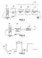
- FIG. 2is a block diagram of a grade crossing gate system constructed in accordance with an exemplary embodiment of the invention.
- FIG. 3is a block diagram of a gate arm moving assembly shown in the system of FIG. 2 .
- FIG. 4is a block diagram of the gate arm moving assembly of the system of FIG. 2 with a transverse flux machine as the motor.
- FIG. 5is a schematic diagram of a pulse width modulated signal sent by a controller shown in the system of FIG. 2 to drive the motor in the gate arm moving assembly at varying speeds.
- FIG. 6is a schematic diagram of a tip position sensor within the position sensor assembly that is in a vertical orientation.
- FIG. 7is a schematic diagram of the tip position sensor in a horizontal orientation.
- FIG. 8is a schematic diagram of a gear position sensor within the position sensor assembly with a gear tooth sensor.
- FIG. 9is a schematic diagram of a shaft position sensor within the position sensor assembly with an encoder disk having continuous pattern cuts.
- FIG. 10is a schematic diagram of a shaft reference position sensor within the position sensor assembly with an encoder disk having predetermined angle cuts.
- FIG. 11illustrates a process for monitoring and controlling the grade crossing gate system of FIG. 2 .
- FIG. 12is a block diagram of the grade crossing gate system constructed in accordance with another exemplary embodiment of the invention.
- FIG. 13is a block diagram of the controller in communication with a remote control unit shown in the system of FIG. 12 .
- FIG. 2is a block diagram of a grade crossing gate system 20 constructed in accordance with an exemplary embodiment of the invention.
- the systemincludes a gate arm moving assembly 62 that moves the gate arm 12 , a position sensor assembly 92 that tracks the position of the gate arm 12 in motion and a gate arm safety monitoring system 142 that monitors the safety of the gate arm 12 .
- the system 20further includes a gate arm intrusion sensing assembly 132 that checks if anything comes in the way of the gate arm 12 and a controller 122 that controls and coordinates the overall functioning of the system.
- the system 20also includes fail-safe electronics 152 .
- the fail-safe electronics 152works in parallel with the controller 122 at all times and ensures that the most important and basic operations of the grade crossing gate system 20 (e.g. bringing the gate arm 12 to an upright position as a default configuration) are executed even in case of any fault with the controller 122 .
- the system 20further includes warning system 162 that is used in general to warn the roadway traffic.
- FIG. 3is a block diagram of one embodiment of the gate arm moving assembly 62 of FIG. 2 .
- the gate arm moving assembly 62uses motor control electronics 82 , a motor 76 and a gear assembly 64 to move the gate arm 12 .
- the motor 76is driven to rotate the main shaft on which gate arm 12 is held.
- This applicationdemands a high torque (e.g., about 150 Newton meter) at very low speeds (e.g., 1–2 revolutions per minute). In one embodiment of this invention, this is achieved by means of multi-stage gear reduction, which reduces the speed and steps up the torque.
- Motor control electronics 82receives a signal from the controller 122 and controls the speed of the motor 76 .
- the motor 76in turn moves the gear assembly 64 .
- a brushed/brushless DC gear motoris used with additional step down gears at the output of the motor to further reduce the speed to the required level of 1–2 rpm.
- this schemethere are multi-level gear reductions from the motor output to the final shaft. For instance, there are three reduction gears in series being driven by the motor 76 —a first reduction gear 66 , a second reduction gear 68 , and a third reduction gear 72 .
- the gate arm 12is driven in the up or down direction by the output shaft of the third reduction gear 72 .
- transverse flux machine 78Another embodiment of the invention involves the use of a transverse flux machine 78 to achieve the appropriate torque-speed combination using at the maximum a single stage gear reduction.
- Transverse flux machine technologyis capable of producing high torque with a high torque-to-weight ratio for the machine.
- This embodiment of the inventioninvolves the use of this high torque machine specifically for driving the gate arm 12 . Since this machine is capable of generating high torques, it can be used to directly drive the gate arm 12 without any gear or with a maximum of single stage gear. Moreover, this is an embodiment of the invention where the space required is reduced.
- FIG. 4shows a block diagram of the gate arm moving assembly 62 of FIG. 2 with a transverse flux machine 78 as the motor.
- Motor control electronics 82receives a signal from the controller 122 and controls the speed of the transverse flux machine 78 .
- the transverse flux machine 78drives the gate arm 12 using the single-stage gear 74 .
- the transverse flux machine 78when used with a single stage gear or with no gear occupies much less space as compared to a conventional DC motor with multi-stage gear reductions.
- the overall efficiencyis higher as the number of gears is reduced or eliminated.
- the transverse flux machine 78 and the single stage gear 74can be mounted directly on the shaft on which the gate arm 12 is mounted so that assembly is easier.
- the number of partsis reduced and the system 20 has a high reliability. Reduced requirements for space due to elimination of multiple gears improves system efficiency because of a reduction in number of gear stages.
- system integrationbecomes easier as there are fewer parts to put together.
- accurate position and speed controlis possible by closed loop control of the transverse flux machine 78 .
- system complexityis reduced due to far less number of mechanical components. Reliability is increased due to reduction in the number of mechanical parts. This embodiment also achieves a reduction in fabrication costs.
- the gate arm moving assembly 62 of both FIG. 3 and FIG. 4 embodimentsreceives an incoming command related to the gate arm from the controller 122 .
- the signal in these embodimentis a Pulse Width Modulated (PWM) signal and it is generated by a micro-controller 124 in the controller 122 and is used to vary the speed of the motor 76 in FIG. 3 or the transverse flux machine 78 in FIG. 4 through a solid state driver (not shown), which in turn moves the gate arm 12 .
- a command from the wayside bungalow 44determines whether the gate arm 12 has to be lowered (i.e., closed) or kept in vertical position (i.e., opened). Once the controller 122 receives a command either to open or close, the motor 76 or the transverse flux machine 78 is activated to position the gate arm 12 accordingly.
- the controller 122deactivates the solenoid, releases the brake and then runs the motor 76 or the transverse flux machine 78 in a forward direction. This brings the gate arm 12 to a ‘closed’ or horizontal position. Again, when the gate has to be opened and the gate arm 12 has to be raised, the motor 76 or the transverse flux machine 78 is made to run in a reverse direction till the gate arm 12 comes to a vertical position. At the end of the travel of gate arm 12 , i.e. at the vertical position, the solenoid is activated again, the brake is applied and thereby the gate arm 12 is held stationary in the vertical position.
- This configuration of the brakeensures a fail-safe operation during power failure.
- the solenoidautomatically gets de-activated and thereby releases the brake.
- the gate arm 12comes down by its own weight and rests in a horizontal position.
- a counterweight(not shown) nearly balances the weight of the gate arm 12 and slows down the downward motion of the gate arm 12 .
- FIG. 5is a schematic diagram of a PWM signal 84 sent by the controller 122 to drive the motor 76 or the transverse flux machine 78 at varying speeds.
- the horizontal axis 86represents a time axis of the PWM signal 84 and the vertical axis 88 represents a voltage axis of the PWM signal 84 .
- the figurerepresents the changing pulse value over time.
- T 1is the cycle time when power is supplied and T 2 is the cycle time when power is not supplied.
- the duty cycle of the signal 84is T 1 /(T 1 +T 2 ).
- Speed of the gate arm 12is varied by controlling the duty cycle of the PWM signal 84 .
- the position of the gate arm 12 in motionis continuously tracked by the controller 122 by deploying another subsystem—the position sensor assembly 92 .
- the position sensor assembly 92includes a tip position sensor 94 , a gear position sensor 108 , a shaft position sensor 112 , and a shaft reference position sensor 114 .
- the position of the gate arm 12is continuously monitored and tracked by position sensor assembly 92 to activate warning systems at different predetermined positions of the gate arm 12 .
- the position of the gate armis sensed right from the vertical position, i.e., 90 degrees, to the horizontal position, i.e., 0 degrees.
- the flashlight 164 and bell 166are also activated at pre-programmed positions to activate their operations appropriately with the help of solid-state switch.
- the up/down indications sensed from tip position sensor 94are sent back to the controller 122 and logged for the gate operations.
- FIG. 6is a schematic diagram of the tip position sensor 94 in a vertical orientation.
- the tip position sensor 94comprises a tube of mercury 102 and mercury switch 104 embedded in the tube.
- the mercury levelfalls below the mercury switch 104 and as a result the circuitry 104 remains electrically open.
- FIG. 7is a schematic diagram of the tip position sensor 94 in a horizontal orientation 98 .
- the mercuryflows over the mercury switch 104 .
- Mercurybeing a metal, the circuit 104 gets closed and the position of the arm is sensed as horizontal.
- FIG. 8is a schematic diagram of the gear position sensor 108 of the system of FIG. 2 with a gear tooth sensor.
- the gear position sensor 108is a proximity sensor mounted in alignment with gear tooth teeth 106 in the system 20 .
- the teeth 106 of the gearpass in front of the proximity sensor 108 one after another. Every time a gear tooth 106 passes in front of the proximity sensor 108 , the proximity sensor 108 senses the movement and produces an output pulse.
- the output pulses from the proximity sensor 108are sent to an electronics read-out logic (not shown), which is a part of the controller 122 .
- the electronics read-out logiccounts the number of output pulses and determines the angular position of the gate arm 12 from the number of output pulses.
- an existing gearis used as a sensing element and so no extra position encoder is required.
- gear tooth sensor 108can be used to sense direction and speed apart from the pulse per tooth of the gear.
- the gear tooth sensor 108can be configured to receive the position count of the gate arm in three different ways in three different embodiments of the invention
- the two-channel gear tooth sensor 108is a ‘quadrature’ sensor.
- the quadrature sensorhas two sensing elements inside the sensor, and it produces two digital pulses per tooth.
- Channel Aleads channel B by 90 degrees if the gear spins clockwise.
- Channel Bleads channel A by 90 degrees if the gear spins counter-clockwise.
- quadrature countersavailable that can resolve the two channels and sense that when traveling clockwise, the counter should see, in order, Channel A—low to high, Channel B—low to high, Channel A—high to low, Channel B—high to low. On any deviation from this order, the counter is programmed to subtract this count and not to add it. So, if the gear chatters, and for instance Channel A goes high, then low, then high, then low, etc., the counter counts up/down/up/down, etc. and the true position stays.
- gear tooth sensor 108is a two-channel sensor with a ‘D flip flop’ Speed/Direction sensing element.
- Gear tooth sensor 108has two digital outputs, one is one pulse per tooth, and the other is direction. When the gear spins clockwise, the direction signal is ‘low’. When the gear spins counter-clockwise, the direction signal is ‘high’.
- This sensoroperates with the same two elements as described above. Inside this sensor, there is a D flip flop (Dff) logic element where Channel A is the input to ‘D’, and the flip flop is clocked with the rising edge of channel B. When spinning, the direction signal is updated once per tooth.
- DffD flip flop
- the gear tooth sensor 108is a ‘Quadrature Counter’ with speed and direction sensor elements. It starts with the two elements and pulses 90 degrees apart. This sensor again produces two digital outputs for speed and direction. Unlike the D flip flop speed/direction sensor described above, this sensor updates direction four times per tooth (every edge). Even if the gear chatters at times, the speed and direction sensors are able to distinguish the two digital output pulses.
- the position sensor assembly 92can also be configured to sense any backlash effect or a jerk of the gate arm 12 .
- the position sensor assembly 92 of this embodimentoffers a low cost and low maintenance solution for the practical problems of distinguishing a backlash or a jerk of the gate arm 12 from a substantial change in position of rest or motion of the gate arm 12 .
- an external gear systemcan also be used along with a proximity sensor.
- a gear tooth sensor 108 and its read-out electronicscan be used to sense the position of the gate arm 12 .
- the read-out electronicsis part of the controller 122 .
- the gear tooth sensor 108can be any other type of proximity sensor, for instance, an eddy current sensor or a Hall effect sensor or a magneto-resistive sensor.
- the position sensor assembly 92also deploys a shaft position sensor 112 and a shaft reference position sensor 114 to track the angular position of the shaft.
- an incremental encoding methodis followed and absolute position of the shaft is detected. Accordingly, as the gate arm 12 moves from its reference, the shaft position sensor 112 produces the pulses per unit distance movement.
- FIG. 9is a schematic diagram of the shaft position sensor 112 of the system of FIG. 2 with an encoder disk 116 having continuous pattern cuts.
- absolute switchinguses a metallic cam type disk 116 , such that whenever an edge of the disk 116 crosses a shaft position sensor 112 , the sensor produces a change in its output.
- the sensor outputis used to detect the angular position of the shaft.
- the metallic cam type disk 116 in this embodimenthas continuous pattern cuts along its circumference. Every time this pattern crosses the sensor 112 , it produces a pulse due to unit angular rotation of the main shaft.
- the position of the gate arm 12as measured from a reference is directly proportional to the pulse count.
- the electronic read-out logic(not shown) is part of the controller 122 and it senses the pulses to give out the exact angular position of the shaft in degrees. That is also the angular position of the gate arm 12 .
- the position sensor assembly 92uses an absolute position detection technique to sense the position of the gate arm 12 .
- FIG. 10is a schematic diagram of the shaft reference position sensor 114 of FIG. 2 .
- An encoder disk 118 with a pattern cut all along its outer circumferenceis used in this embodiment of the position sensor assembly 92 .
- the encoder disk 118can have a 90 degrees sector cut along its circumference.
- the depth of the cutcan vary from one embodiment to another. In one embodiment, the depth of the cut can be the full the thickness of the encoder disk. In another embodiment, the cut can be less than the thickness of the encoder disk. In operation, whenever the cut-edge of the encoder disk 118 passes the sensor 114 , the sensor output changes. In another embodiment, a number of encoder disks 118 can be aligned and mounted on the main shaft to get differential angular measurement of the shaft.
- the position sensor assembly 92is used for activating different warning systems of the grade crossing gate system 20 .
- the position sensor assembly 92uses the output pulses from the gear tooth sensor 108 of the grade crossing gate system 20 to sense the position of the gate arm 12 by using the following relationship:
- This embodiment of the inventionis capable of position detection at any required angle. It is also easy to adjust the position of the encoder disks to any required angle. The operation is completely non-contact position sensor in method and switching.
- the signals sent from the position sensor assembly 92 to the controller 122can also be used to activate different warning systems of the railroad grade crossing gate system 20 .
- the warning system 162includes a warning flashlight 164 and a warning bell 166 . Timing of the warning systems 164 and 166 depends on the position of the gate arm 12 as sensed by the position sensor assembly 92 .
- the gate system 20uses the position of the gate arm 12 to activate the warning system.
- the position of the gate arm 12is also used to control the motor, which drives the gate arm main shaft using external gear.
- This embodiment of the inventionuses the position sensor assembly 92 that in turn uses the existing gear of the gate system 20 to get the position of the gate arm 12 in degrees.
- the inventionis not limited to the above-described functions of the position sensor assembly 92 .
- the position sensor assembly 92can also be configured to sense any backlash effect or a jerk of the gate arm 12 .
- the position sensor assembly 92indicates speed, direction and position of the gate arm 12 . These extra parameters can be used for motor control and safety logics to improve the performance of the whole grade crossing system 20 .
- a combination of data obtained from the position sensors 94 , 108 , 112 or 114can also be used to sense a situation where the gate arm 12 is inadvertently intercepted on its motion.
- the gate arm safety monitoring system 142monitors the safety of the gate arm 12 from any potential damage all through its motion.
- the gate arm safety monitoring system 142includes a stress detection system 144 and a stress threshold detection circuitry 146 .
- the stress detection system 144determines the stress level at the base of the fixture holding the gate arm 12 .
- the stress threshold detection circuitry 146is analog circuitry that compares the stress level sensed with a predetermined threshold value and sends an appropriate warning signal that the gate arm 12 is damaged.
- the stress threshold detection circuitry 146is also used to send this information back to the way-side bungalow 44 for immediate replacement of the gate arm 12 to enhance the safety of road vehicles.
- the gate arm safety monitoring system 142may have the capability of detecting the strain variation at the shear joint bolts of the railroad crossing gate arm 12 .
- the stress detection system 144would be placed in a way so that the sensitivity is optimum and the routing the electrical wiring does not interfere with the operation of the gate arm 12 .
- the gate arm safety monitoring system 142is deployed to detect any breakage or bending of the gate arm 12 . This information is used for taking necessary corrective actions.
- the gate arm 12is designed in such a way that it tears off at a shear joint bolts position to protect the supporting controller 122 in the event of a vehicular collision.
- the stress detecting systemwhich may be a strain gauge 144 , is placed at the base of the gate arm 12 and the outputs are sent to the stress threshold detection circuitry 146 . Under break or bend situations, a finite amount of stress is generated at the shear joint bolts position. This is detected by the stress threshold detection circuitry 146 and, subsequently, a break or bend decision is formulated.
- strain gauges at the shear joint bolts positionis done in such a way that optimum sensitivity to the breakage or bending of the gate arm 12 is detected. This arrangement does not affect the intended operation of gate arm 12 . It should be appreciated that other types of stress detecting elements can also be used.
- the gate arm intrusion sensing assembly 132continuously monitors whether there is any potential intrusion into the path of motion of the gate arm 12 .
- the gate arm intrusion sensing assembly 132includes an arm position sensor 134 and a motor current sensor 136 .
- the gate arm 12uses itself as an antenna and initiates the micro-power radio frequency (RF) radiation only during operation of gate system, i.e., while closing and opening the gate. If any object comes in the vicinity of gate arm 12 and intercepts the RF waves, the reflected RF waves indicate that an obstructing object is present. This detection is further used in the grade crossing gate system 20 to give feedback to the warning system 162 and to initiate necessary contingency warning action.
- the gate arm intrusion sensing assembly 132improves the fault diagnosis and control of the grade crossing gate system 20 .
- the highway grade crossing gate system 20lowers its arm 12 to block vehicle access and raises its arm 12 to an upright position to permit vehicle access across a railroad crossing.
- vehicles, pedestrians or any other objectscan come under the gate arm 12 and therefore can block the operation of gate system 20 to close/open the gate.
- a vehicle or a pedestrianmay pass through the ‘entry’ gate and then get stranded in between the ‘entry’ and the ‘exit’ gates.
- a methodis described by which objects causing gate arm intrusion and thereby hindering the operation of grade crossing gate system 20 can be identified.
- the gate arm intrusion sensing assembly 132senses the position of the gate arm 12 using the arm position sensor 134 .
- the gate arm intrusion sensing assembly 132also senses the motor current flowing through the motor 76 using the motor current sensor 136 . If the position of the arm 12 is sensed to be unchanging and if at the same time the motor current tends to increase, it indicates that the motor 76 is trying to overcome a resistance on the motion of the gate arm 12 . The intrusion on the gate arm 12 is thus confirmed. This is a proactive method of detection of intrusion where the detection happens before any contact between an intruding object and the gate arm 12 .
- the fail-safe electronics 152take over the command from the controller 122 in time of a power failure and failure of any other kind.
- Fail-safe electronics 152include fail-safe logic circuitry 154 and a fail-safe timer 156 .
- the fail-safe electronics 152uses discrete hardware to complement the controller 122 , which takes care of a minimum required operation of the gate system 20 during failure of the micro-controller 124 . One such operation is bringing the gate arm 12 down to a horizontal position during a failure.
- the fail-safe timer 156synchronizes the operation of the fail-safe logic circuitry 154 in keeping with an internal clock.
- Embodiments of the inventionare not limited to the above-described functionalities of the fail-safe electronics 152 . There are many other fail-time operations that can be performed by the fail-safe electronics 152 such as activating the warning system 162 and its components like the flashlight 164 and warning bell 166 .
- the controller 122is the central unit that controls and coordinates all the activities of the grade crossing gate system 20 .
- the controller 122includes a micro-controller 124 and a solid state switch 126 configured to communicate in power-line communication mode.
- the micro-controller 124is an analog-to-digital converter accessible through all analog input port. The function of the micro-controller 124 is to convert the analog D.C. voltage to a digital format recognizable by the central processing unit.
- the micro-controller 124 in the controller 122has two modes—“operation mode” and “maintenance mode”. The mode is selected using a maintenance switch operated by the maintenance/operational engineer. In “operation mode”, the controller continuously tracks for the external command. If the gate system 20 is commanded to lower the gate arm 12 , then the controller 122 generates a pulse width modulated (PWM) signal to drive the motor to horizontally position the gate arm 12 . In “maintenance mode”, field data and a maintenance log in a flash memory are accessed using a hand held system or by a remote terminal. Field programmability improves the maintenance of the system and helps in developing maintenance information related to the lifetime management of the grade crossing gate system.
- PWMpulse width modulated
- Embodiments of the inventionare not limited to the above-described configuration of the micro-controller 124 .
- the controller 122may include solid-state equipment, relays, microprocessors, software, hardware, firmware, etc. or combinations thereof.
- the controller 122includes logic for activating the gate arm moving assembly 62 in coordination with the position sensor assembly 92 . This way, the controller 122 moves the gate arm 12 and at the same time, tracks the position of the gate arm 12 in motion by using a non-contact position sensor methodology as described above.
- the logic of operation of the controller 122also includes coordination with the operation of the gate arm safety monitoring system 142 for monitoring the safety of the gate arm 12 and coordination with the operation of the gate arm intrusion sensing assembly 132 for detecting if anything comes in the way of the gate arm 12 .
- the controller 122matches the output of the position sensor assembly 92 with the motor current sensor to determine whether there is any increase in the motor current and thereby ascertains any intrusion. All other read-out logic circuits in the system 20 are structurally and functionally part of the controller 122 .
- the controller 122activates appropriate fail-time or warning alerts if a threshold level of any excitation is exceeded.
- the command signals issued by the controller 122may take the form of a simple go/no-go decision wherein proper and improper performances are differentiated. Alternatively, more robust information may be developed depending upon the type of situation being monitored, the sophistication of the sensor involved and logic performed by controller 122 . For example, a history of field or performance data may be recorded with future performance being predicted on the basis of the data trend. For audio performance data, the information may include volume, frequency, and pattern of sound verses time. For visual performance data, the information may include wavelength, intensity and pattern of light verses time. One may appreciate that the information stored by the controller 122 is directly responsive to known failure modes and performance characteristics of the particular type of situation being monitored.
- the controlleris equipped with power-line communication enabled circuitry 126 to communicate in power-line communication mode. Power-line communication mode is explained below in greater details.
- the controller 122may be equipped to communicate with contact based sensing operations.
- the controller 122may be located outside the grade crossing system and within a wayside equipment box near the grade crossing gate system 20 .
- Field data and maintenance logare stored in non-volatile memory connected to the controller 122 .
- the dataare accessed using a hand held system or by a remote control unit 44 for further analysis. For instance, a change in the time interval between the delivery of a command signal and the operation of the gate arm 12 may be indicative of a developing problem.
- Early recognition of a change in the system characteristicsmay permit problems to be fixed before they result in a condition wherein the component or a subsystem fails to respond in a safe manner.
- microcontroller 124 of the gate arm controller 122is enhanced with an additional feature of ‘field programmability’.
- This featureensures that the software program of the microcontroller 124 can be readily changed or updated when needed. The need to change or update the program may arise, for instance, when a fault is diagnosed in the previous version of the program or a change takes place in an operating regulation of FRA or a new regulation is brought in force, etc.
- the software program of the microcontroller 124can be changed or updated using a hand-held system or from a remote control unit.
- the ‘field programmability’ featureeliminates the need to uninstall the whole controller 122 or its microcontroller 124 and send it to a factory for maintenance.
- the overall operation of the system 20is illustrated in FIG. 11 using a process flow chart.
- the processstarts with sensing an incoming command as in step 182 followed by sensing an initial position of the gate arm 12 as in step 184 .
- the controller 122sends a signal to move the gate arm 12 in step 186 .
- step 188it is determined whether the operation is fail-safe at all times. In case of any failure of operation, there is a take-over by the fail-safe electronics in step 192 and fail-safe takeover alert is activated in step 222 .
- safety of the gate arm 12is assessed in step 196 and gate arm safety alert 224 is generated in case the gate arm 12 is sensed not to be safe any more.
- An intrusion on gate arm 12is proactively sensed in step 198 .
- This stepincludes checking for a change in the position of the gate arm 12 as in step 202 and checking for a change in the motor current 204 concurrently. At any time, if the position of the gate arms 12 does not change and the motor current also increases at the same time, it is confirmed that the motion of the gate arm 12 is intruded. Gate arm intrusion alert 226 is activated at that instant.
- the position of the gate arm 12is continuously monitored by different non-contact methods e.g., by sensing relative rotation of gear as in step 206 , sensing absolute rotation of shaft as in step 208 , and sensing position of the tip of the gate arm 12 as in step 212 .
- the controller 122waits for a next command as in step 216 .
- the micro-controller 124 of the controller 122operates in two modes—“operation mode” and “maintenance mode”. The mode is selected using a maintenance switch, operated by the maintenance/operational engineer.
- FIG. 12is a block diagram of a grade crossing gate system 30 constructed in accordance with this exemplary embodiment of the invention.
- the system 30is similar to the system 20 of FIG. 2 , except that this embodiment includes a remote control unit 44 to communicate with the gate arm controller 122 of the grade crossing gate system 30 from a remote location.
- the remote control unit 44includes a microcontroller 46 and a power-line communication module 172 .
- the power-line communication module 172enables power-line communication between the remote control unit controller 46 and the gate arm controller 122 .
- Remote control unit 44may take any form, such as a wireless, landline, and/or fiber optic communications system having a transmitter and a remote receiver. Remote control unit 44 may include and make use of access to the Internet or other global information network.
- a remote control unit controller 46such as a computerized data processor or an analog micro-controller operated by a railroad or rail crossing service provider, may receive the communication signals from the controller 122 . Communication signals from the controller 122 may be received by the remote control unit controller 46 regarding the operation or malfunction of a number of components or subsystems. The readiness of grade crossing gate systems throughout the network may thus be easily and automatically monitored at a central location.
- the remote control unitmay have an additional database to store different operational and field maintenance data in relation to different components, subsystems and the system 40 .
- data regarding the make, model, location, installation date, service history, etc. of each a component or a subsystem throughout the networkmay be maintained in a database accessible by the remote control unit controller 46 . Similar communication may be transmitted from the remote control unit controller 46 to the grade crossing system controller 122 in relation to operation of a number of components or subsystems.
- FIG. 13is a block diagram of the gate arm controller 122 in communication with the remote control unit 44 of FIG. 12 .
- the communication lines in the system of FIG. 13include a command carrying line 174 , a power-line communication line 176 and a ground line 178 .
- a command carrying line 174typically there are two communication lines between a receiving unit and a transmitting unit. One of the lines carries power and the other line is grounded.
- the power-line 176is configured to additionally carry the intended communication between the gate arm controller 122 and the remote control unit 44 .
- the two-way communication provided by the grade crossing gate system 30 of FIG. 12may be used to augment the normal flow of control commands as well as to ensure better quality, reliability, maintainability and operability of the grade crossing gate system.
- Wireless communication modefurther includes communication in radio frequency mode. Communication in wireless is helpful for applications, which are powered using solar panels. In such applications, power is supplied locally and there is no power line connecting the grade crossing gate system 30 and the remote control unit or the wayside bungalow 44 . The communication between the grade crossing gate system 30 and remote control unit or the wayside bungalow 44 happens in such cases using wireless signals.
Landscapes
- Engineering & Computer Science (AREA)
- Mechanical Engineering (AREA)
- Train Traffic Observation, Control, And Security (AREA)
Abstract
Description
Claims (29)
Priority Applications (3)
| Application Number | Priority Date | Filing Date | Title |
|---|---|---|---|
| US10/881,959US7195211B2 (en) | 2004-06-29 | 2004-06-29 | Electronically controlled grade crossing gate system and method |
| CA002510618ACA2510618A1 (en) | 2004-06-29 | 2005-06-23 | Electronically controlled grade crossing gate system and method |
| US11/675,321US20070130834A1 (en) | 2004-06-29 | 2007-02-15 | Electronically controlled grade crossing gate system and method |
Applications Claiming Priority (1)
| Application Number | Priority Date | Filing Date | Title |
|---|---|---|---|
| US10/881,959US7195211B2 (en) | 2004-06-29 | 2004-06-29 | Electronically controlled grade crossing gate system and method |
Related Child Applications (1)
| Application Number | Title | Priority Date | Filing Date |
|---|---|---|---|
| US11/675,321DivisionUS20070130834A1 (en) | 2004-06-29 | 2007-02-15 | Electronically controlled grade crossing gate system and method |
Publications (2)
| Publication Number | Publication Date |
|---|---|
| US20050284987A1 US20050284987A1 (en) | 2005-12-29 |
| US7195211B2true US7195211B2 (en) | 2007-03-27 |
Family
ID=35504570
Family Applications (2)
| Application Number | Title | Priority Date | Filing Date |
|---|---|---|---|
| US10/881,959Expired - LifetimeUS7195211B2 (en) | 2004-06-29 | 2004-06-29 | Electronically controlled grade crossing gate system and method |
| US11/675,321AbandonedUS20070130834A1 (en) | 2004-06-29 | 2007-02-15 | Electronically controlled grade crossing gate system and method |
Family Applications After (1)
| Application Number | Title | Priority Date | Filing Date |
|---|---|---|---|
| US11/675,321AbandonedUS20070130834A1 (en) | 2004-06-29 | 2007-02-15 | Electronically controlled grade crossing gate system and method |
Country Status (2)
| Country | Link |
|---|---|
| US (2) | US7195211B2 (en) |
| CA (1) | CA2510618A1 (en) |
Cited By (62)
| Publication number | Priority date | Publication date | Assignee | Title |
|---|---|---|---|---|
| US20070130834A1 (en)* | 2004-06-29 | 2007-06-14 | General Electric Company | Electronically controlled grade crossing gate system and method |
| US20080296442A1 (en)* | 2007-06-04 | 2008-12-04 | Andrew Lawrence Ruggiero | Methods and systems for verifying the operation of a railroad gate |
| US20090184214A1 (en)* | 2008-01-17 | 2009-07-23 | Lockheed Martin Corporation | System and Method for Train Operation Approaching Grade Crossings |
| US20090194642A1 (en)* | 2007-10-30 | 2009-08-06 | Railway Equipment Company | Gate monitoring system |
| US7619407B2 (en) | 2008-04-10 | 2009-11-17 | Magic Technologies, Inc. | Gear tooth sensor with single magnetoresistive bridge |
| US20090315543A1 (en)* | 2008-06-24 | 2009-12-24 | Magic Technologies, Inc. | Gear tooth sensor (GTS) with magnetoresistive bridge |
| US20100106308A1 (en)* | 2008-10-27 | 2010-04-29 | Lennox Industries, Inc. | System and method for zoning a distributed-architecture heating, ventilation and air conditioning network |
| USD648642S1 (en) | 2009-10-21 | 2011-11-15 | Lennox Industries Inc. | Thin cover plate for an electronic system controller |
| USD648641S1 (en) | 2009-10-21 | 2011-11-15 | Lennox Industries Inc. | Thin cover plate for an electronic system controller |
| US8239066B2 (en) | 2008-10-27 | 2012-08-07 | Lennox Industries Inc. | System and method of use for a user interface dashboard of a heating, ventilation and air conditioning network |
| US8255086B2 (en) | 2008-10-27 | 2012-08-28 | Lennox Industries Inc. | System recovery in a heating, ventilation and air conditioning network |
| US8260444B2 (en) | 2010-02-17 | 2012-09-04 | Lennox Industries Inc. | Auxiliary controller of a HVAC system |
| US8295981B2 (en) | 2008-10-27 | 2012-10-23 | Lennox Industries Inc. | Device commissioning in a heating, ventilation and air conditioning network |
| US8352081B2 (en) | 2008-10-27 | 2013-01-08 | Lennox Industries Inc. | Communication protocol system and method for a distributed-architecture heating, ventilation and air conditioning network |
| US8352080B2 (en) | 2008-10-27 | 2013-01-08 | Lennox Industries Inc. | Communication protocol system and method for a distributed-architecture heating, ventilation and air conditioning network |
| US8433446B2 (en) | 2008-10-27 | 2013-04-30 | Lennox Industries, Inc. | Alarm and diagnostics system and method for a distributed-architecture heating, ventilation and air conditioning network |
| US8437877B2 (en) | 2008-10-27 | 2013-05-07 | Lennox Industries Inc. | System recovery in a heating, ventilation and air conditioning network |
| US8437878B2 (en) | 2008-10-27 | 2013-05-07 | Lennox Industries Inc. | Alarm and diagnostics system and method for a distributed architecture heating, ventilation and air conditioning network |
| US8442693B2 (en) | 2008-10-27 | 2013-05-14 | Lennox Industries, Inc. | System and method of use for a user interface dashboard of a heating, ventilation and air conditioning network |
| US8452456B2 (en) | 2008-10-27 | 2013-05-28 | Lennox Industries Inc. | System and method of use for a user interface dashboard of a heating, ventilation and air conditioning network |
| US8452906B2 (en) | 2008-10-27 | 2013-05-28 | Lennox Industries, Inc. | Communication protocol system and method for a distributed-architecture heating, ventilation and air conditioning network |
| US8463442B2 (en) | 2008-10-27 | 2013-06-11 | Lennox Industries, Inc. | Alarm and diagnostics system and method for a distributed architecture heating, ventilation and air conditioning network |
| US8463443B2 (en) | 2008-10-27 | 2013-06-11 | Lennox Industries, Inc. | Memory recovery scheme and data structure in a heating, ventilation and air conditioning network |
| US8543243B2 (en) | 2008-10-27 | 2013-09-24 | Lennox Industries, Inc. | System and method of use for a user interface dashboard of a heating, ventilation and air conditioning network |
| US8548630B2 (en) | 2008-10-27 | 2013-10-01 | Lennox Industries, Inc. | Alarm and diagnostics system and method for a distributed-architecture heating, ventilation and air conditioning network |
| US8560125B2 (en) | 2008-10-27 | 2013-10-15 | Lennox Industries | Communication protocol system and method for a distributed-architecture heating, ventilation and air conditioning network |
| US8564400B2 (en) | 2008-10-27 | 2013-10-22 | Lennox Industries, Inc. | Communication protocol system and method for a distributed-architecture heating, ventilation and air conditioning network |
| US8600559B2 (en) | 2008-10-27 | 2013-12-03 | Lennox Industries Inc. | Method of controlling equipment in a heating, ventilation and air conditioning network |
| US8600558B2 (en) | 2008-10-27 | 2013-12-03 | Lennox Industries Inc. | System recovery in a heating, ventilation and air conditioning network |
| US8615326B2 (en) | 2008-10-27 | 2013-12-24 | Lennox Industries Inc. | System and method of use for a user interface dashboard of a heating, ventilation and air conditioning network |
| US8655490B2 (en) | 2008-10-27 | 2014-02-18 | Lennox Industries, Inc. | System and method of use for a user interface dashboard of a heating, ventilation and air conditioning network |
| US8655491B2 (en) | 2008-10-27 | 2014-02-18 | Lennox Industries Inc. | Alarm and diagnostics system and method for a distributed architecture heating, ventilation and air conditioning network |
| US8661165B2 (en) | 2008-10-27 | 2014-02-25 | Lennox Industries, Inc. | Device abstraction system and method for a distributed architecture heating, ventilation and air conditioning system |
| US8694164B2 (en) | 2008-10-27 | 2014-04-08 | Lennox Industries, Inc. | Interactive user guidance interface for a heating, ventilation and air conditioning system |
| US8725298B2 (en) | 2008-10-27 | 2014-05-13 | Lennox Industries, Inc. | Alarm and diagnostics system and method for a distributed architecture heating, ventilation and conditioning network |
| US8744629B2 (en) | 2008-10-27 | 2014-06-03 | Lennox Industries Inc. | System and method of use for a user interface dashboard of a heating, ventilation and air conditioning network |
| US8762666B2 (en) | 2008-10-27 | 2014-06-24 | Lennox Industries, Inc. | Backup and restoration of operation control data in a heating, ventilation and air conditioning network |
| US8774210B2 (en) | 2008-10-27 | 2014-07-08 | Lennox Industries, Inc. | Communication protocol system and method for a distributed-architecture heating, ventilation and air conditioning network |
| US8788100B2 (en) | 2008-10-27 | 2014-07-22 | Lennox Industries Inc. | System and method for zoning a distributed-architecture heating, ventilation and air conditioning network |
| US8798796B2 (en) | 2008-10-27 | 2014-08-05 | Lennox Industries Inc. | General control techniques in a heating, ventilation and air conditioning network |
| US8802981B2 (en) | 2008-10-27 | 2014-08-12 | Lennox Industries Inc. | Flush wall mount thermostat and in-set mounting plate for a heating, ventilation and air conditioning system |
| US8855825B2 (en) | 2008-10-27 | 2014-10-07 | Lennox Industries Inc. | Device abstraction system and method for a distributed-architecture heating, ventilation and air conditioning system |
| US8874815B2 (en) | 2008-10-27 | 2014-10-28 | Lennox Industries, Inc. | Communication protocol system and method for a distributed architecture heating, ventilation and air conditioning network |
| US8892797B2 (en) | 2008-10-27 | 2014-11-18 | Lennox Industries Inc. | Communication protocol system and method for a distributed-architecture heating, ventilation and air conditioning network |
| US8977794B2 (en) | 2008-10-27 | 2015-03-10 | Lennox Industries, Inc. | Communication protocol system and method for a distributed-architecture heating, ventilation and air conditioning network |
| US8994539B2 (en) | 2008-10-27 | 2015-03-31 | Lennox Industries, Inc. | Alarm and diagnostics system and method for a distributed-architecture heating, ventilation and air conditioning network |
| US9152155B2 (en) | 2008-10-27 | 2015-10-06 | Lennox Industries Inc. | Device abstraction system and method for a distributed-architecture heating, ventilation and air conditioning system |
| US9261888B2 (en) | 2008-10-27 | 2016-02-16 | Lennox Industries Inc. | System and method of use for a user interface dashboard of a heating, ventilation and air conditioning network |
| US9268345B2 (en) | 2008-10-27 | 2016-02-23 | Lennox Industries Inc. | System and method of use for a user interface dashboard of a heating, ventilation and air conditioning network |
| US9325517B2 (en) | 2008-10-27 | 2016-04-26 | Lennox Industries Inc. | Device abstraction system and method for a distributed-architecture heating, ventilation and air conditioning system |
| US9377768B2 (en) | 2008-10-27 | 2016-06-28 | Lennox Industries Inc. | Memory recovery scheme and data structure in a heating, ventilation and air conditioning network |
| US9432208B2 (en) | 2008-10-27 | 2016-08-30 | Lennox Industries Inc. | Device abstraction system and method for a distributed architecture heating, ventilation and air conditioning system |
| US9632490B2 (en) | 2008-10-27 | 2017-04-25 | Lennox Industries Inc. | System and method for zoning a distributed architecture heating, ventilation and air conditioning network |
| US9678486B2 (en) | 2008-10-27 | 2017-06-13 | Lennox Industries Inc. | Device abstraction system and method for a distributed-architecture heating, ventilation and air conditioning system |
| CN107905148A (en)* | 2017-12-10 | 2018-04-13 | 柳州市力万科技有限公司 | Electric railing control system |
| US20180346003A1 (en)* | 2017-06-01 | 2018-12-06 | Siemens Industry, Inc. | Railroad crossing gate monitoring and alarm system |
| RU193496U1 (en)* | 2019-06-06 | 2019-10-30 | Сергей Алексеевич Виноградов | RAILWAY SECURITY CONTROL DEVICE |
| US11273854B2 (en) | 2018-05-21 | 2022-03-15 | C.D.L. Electric Company, Inc. | User interface for grade crossing gate controller |
| US11411514B2 (en) | 2019-09-13 | 2022-08-09 | Rolls-Royce Corporation | Electric machine with torque control |
| US20230093221A1 (en)* | 2021-09-23 | 2023-03-23 | Railway Equipment Company, Inc. | Warning light control system with variable flashing rate |
| US20230109820A1 (en)* | 2021-10-11 | 2023-04-13 | C.D.L. Electric Company, Inc. | Quick-replacement gear for grade crossing gate mechanism |
| US20230118555A1 (en)* | 2021-10-20 | 2023-04-20 | Railway Equipment Company, Inc. | Warning light assembly with orientation sensor, and railway crossing installation including the same |
Families Citing this family (35)
| Publication number | Priority date | Publication date | Assignee | Title |
|---|---|---|---|---|
| US20150235094A1 (en) | 2014-02-17 | 2015-08-20 | General Electric Company | Vehicle imaging system and method |
| US11124207B2 (en) | 2014-03-18 | 2021-09-21 | Transportation Ip Holdings, Llc | Optical route examination system and method |
| US20110285842A1 (en)* | 2002-06-04 | 2011-11-24 | General Electric Company | Mobile device positioning system and method |
| US9919723B2 (en) | 2002-06-04 | 2018-03-20 | General Electric Company | Aerial camera system and method for determining size parameters of vehicle systems |
| US9875414B2 (en) | 2014-04-15 | 2018-01-23 | General Electric Company | Route damage prediction system and method |
| US9873442B2 (en) | 2002-06-04 | 2018-01-23 | General Electric Company | Aerial camera system and method for identifying route-related hazards |
| US10110795B2 (en) | 2002-06-04 | 2018-10-23 | General Electric Company | Video system and method for data communication |
| US20080061948A1 (en)* | 2006-08-18 | 2008-03-13 | Daniel Perez | System and method for communicating with gate operators via a power line |
| US20080099633A1 (en)* | 2006-10-31 | 2008-05-01 | Quantum Engineering, Inc. | Method and apparatus for sounding horn on a train |
| US8028961B2 (en)* | 2006-12-22 | 2011-10-04 | Central Signal, Llc | Vital solid state controller |
| US7908114B2 (en)* | 2007-05-15 | 2011-03-15 | General Electric Company | System and method for aligning a railroad signaling system |
| CZ305310B6 (en)* | 2008-06-16 | 2015-07-29 | Ažd Praha S. R. O. | Method of controlling and checking mechanical caution of light level crossing warning systems employing electromechanical drive of barrier and apparatus for making the same |
| US7950608B2 (en)* | 2008-11-04 | 2011-05-31 | Progress Rai Services Corp | System, method and apparatus for railroad gate flasher assembly having a sealed, rodent-proof connection between in-place foundation and utility mast |
| EP2576316A2 (en) | 2010-05-31 | 2013-04-10 | Central Signal, LLC | Train detection |
| JP5743318B2 (en)* | 2011-02-09 | 2015-07-01 | 大同信号株式会社 | Railroad crossing breaker |
| JP6076045B2 (en)* | 2012-11-02 | 2017-02-08 | 大同信号株式会社 | Railroad crossing breaker |
| US8898965B1 (en)* | 2013-02-22 | 2014-12-02 | Railroad Signal International, LLC | Integral solar/wind turbine railroad signal bungalow assembly |
| US9338526B2 (en)* | 2013-04-04 | 2016-05-10 | Behrouz Golabil | Enhanced updating of control mechanisms |
| US9272721B2 (en)* | 2013-04-18 | 2016-03-01 | Siemens Industry, Inc. | User configurable horizontal brake feature for railroad crossing gates |
| DE102014218883A1 (en)* | 2014-09-19 | 2016-03-24 | Siemens Aktiengesellschaft | Method for determining the position of a barrier in a barrier-shaft drive and barrier-shaft drive |
| US9809237B2 (en)* | 2016-01-29 | 2017-11-07 | Siemens Industry, Inc. | Gate crossing arm collision detection system and method |
| CA2991900A1 (en)* | 2017-01-13 | 2018-07-13 | David K. Fox | Railroad crossing gate lamp system |
| WO2019199310A1 (en)* | 2018-04-12 | 2019-10-17 | Siemens Industry, Inc. | A highway grade crossing gate system including a gate mechanism to rotate a gate arm with human machine interface and voltage reduction circuit |
| US11938985B2 (en)* | 2019-06-11 | 2024-03-26 | Siemens Mobility, Inc. | Smart cam for digitalization of a gate mechanism |
| US12012137B2 (en) | 2019-09-24 | 2024-06-18 | Railway Equipment Company, Inc. | Railroad crossing gate light out detector apparatus and method |
| US11052929B1 (en)* | 2020-01-03 | 2021-07-06 | Westinghouse Air Brake Technologies Corporation | Obstruction detection system |
| JP7690292B2 (en)* | 2020-01-24 | 2025-06-10 | 日本信号株式会社 | Method and device for measuring the operation time of a barrier rod, and barrier device and monitoring device using the same |
| US20230271639A1 (en)* | 2020-08-06 | 2023-08-31 | Siemens Mobility, Inc. | Reconfigurable pcb for brake operation of exit and entrance crossing gate mechanism |
| US12095401B2 (en)* | 2021-06-25 | 2024-09-17 | Siemens Mobility, Inc. | Dynamic load system and method for simulating a crossing gate mechanism |
| PL243918B1 (en)* | 2021-07-21 | 2023-10-30 | Politechnika Swietokrzyska | A set of barrier drive shaft position sensors |
| US12384435B2 (en)* | 2021-08-24 | 2025-08-12 | Siemens Mobility, Inc. | Automated counterbalance system and method for determining counterbalance and adjusting counterweights of a crossing gate |
| US20240034376A1 (en)* | 2022-07-28 | 2024-02-01 | Siemens Mobility, Inc. | Device and method for responding to loss-of-brake on a railroad crossing gate mechanism |
| US20240034370A1 (en)* | 2022-07-28 | 2024-02-01 | Siemens Mobility, Inc. | Device and method for detecting and controlling an arm position of a railroad crossing gate mechanism |
| US12384436B2 (en) | 2022-08-19 | 2025-08-12 | Siemens Mobility, Inc. | Device and method for detecting an obstruction of a railroad crossing gate |
| US20240194047A1 (en)* | 2022-12-13 | 2024-06-13 | Siemens Mobility, Inc. | Crossing gate mechanism with integrated maintenance status alarm |
Citations (11)
| Publication number | Priority date | Publication date | Assignee | Title |
|---|---|---|---|---|
| US3964704A (en) | 1974-09-23 | 1976-06-22 | Harmon Industries, Inc. | Operating mechanism for railroad crossing gate |
| US3987989A (en) | 1974-04-05 | 1976-10-26 | Erico Rail Products Company | Railway signal system |
| US4090685A (en) | 1977-02-22 | 1978-05-23 | Westinghouse Air Brake Company | Grade crossing assembly |
| US5712521A (en)* | 1991-11-22 | 1998-01-27 | Detela; Andrej | Hybrid synchronous machine with transverse magnetic flux |
| US5834914A (en) | 1997-09-08 | 1998-11-10 | Safetran Systems Corporation | Railroad crossing gate mechanism control system |
| US6105905A (en) | 1999-01-25 | 2000-08-22 | Spence; Roy | Railway gate system |
| US6161438A (en)* | 1998-10-20 | 2000-12-19 | Wayne-Dalton Corp. | System and related methods for detecting a force profile deviation of a garage door |
| US6267332B1 (en)* | 2000-01-07 | 2001-07-31 | Robert E. Almblad | Railroad safety system |
| US6307339B1 (en)* | 1998-11-23 | 2001-10-23 | Western-Cullen-Hayes, Inc. | Bi-directionally dynamically braked gate crossing mechanism controller |
| US6688561B2 (en) | 2001-12-27 | 2004-02-10 | General Electric Company | Remote monitoring of grade crossing warning equipment |
| US6863246B2 (en)* | 2002-12-31 | 2005-03-08 | Quantum Engineering, Inc. | Method and system for automated fault reporting |
Family Cites Families (1)
| Publication number | Priority date | Publication date | Assignee | Title |
|---|---|---|---|---|
| US7195211B2 (en)* | 2004-06-29 | 2007-03-27 | General Electric Company | Electronically controlled grade crossing gate system and method |
- 2004
- 2004-06-29USUS10/881,959patent/US7195211B2/ennot_activeExpired - Lifetime
- 2005
- 2005-06-23CACA002510618Apatent/CA2510618A1/ennot_activeAbandoned
- 2007
- 2007-02-15USUS11/675,321patent/US20070130834A1/ennot_activeAbandoned
Patent Citations (11)
| Publication number | Priority date | Publication date | Assignee | Title |
|---|---|---|---|---|
| US3987989A (en) | 1974-04-05 | 1976-10-26 | Erico Rail Products Company | Railway signal system |
| US3964704A (en) | 1974-09-23 | 1976-06-22 | Harmon Industries, Inc. | Operating mechanism for railroad crossing gate |
| US4090685A (en) | 1977-02-22 | 1978-05-23 | Westinghouse Air Brake Company | Grade crossing assembly |
| US5712521A (en)* | 1991-11-22 | 1998-01-27 | Detela; Andrej | Hybrid synchronous machine with transverse magnetic flux |
| US5834914A (en) | 1997-09-08 | 1998-11-10 | Safetran Systems Corporation | Railroad crossing gate mechanism control system |
| US6161438A (en)* | 1998-10-20 | 2000-12-19 | Wayne-Dalton Corp. | System and related methods for detecting a force profile deviation of a garage door |
| US6307339B1 (en)* | 1998-11-23 | 2001-10-23 | Western-Cullen-Hayes, Inc. | Bi-directionally dynamically braked gate crossing mechanism controller |
| US6105905A (en) | 1999-01-25 | 2000-08-22 | Spence; Roy | Railway gate system |
| US6267332B1 (en)* | 2000-01-07 | 2001-07-31 | Robert E. Almblad | Railroad safety system |
| US6688561B2 (en) | 2001-12-27 | 2004-02-10 | General Electric Company | Remote monitoring of grade crossing warning equipment |
| US6863246B2 (en)* | 2002-12-31 | 2005-03-08 | Quantum Engineering, Inc. | Method and system for automated fault reporting |
Cited By (80)
| Publication number | Priority date | Publication date | Assignee | Title |
|---|---|---|---|---|
| US20070130834A1 (en)* | 2004-06-29 | 2007-06-14 | General Electric Company | Electronically controlled grade crossing gate system and method |
| US20080296442A1 (en)* | 2007-06-04 | 2008-12-04 | Andrew Lawrence Ruggiero | Methods and systems for verifying the operation of a railroad gate |
| US7789348B2 (en) | 2007-06-04 | 2010-09-07 | General Electric Company | Methods and systems for verifying the operation of a railroad gate |
| US9205852B2 (en)* | 2007-10-30 | 2015-12-08 | Railway Equipment Company, Inc. | Gate monitoring system |
| US20090194642A1 (en)* | 2007-10-30 | 2009-08-06 | Railway Equipment Company | Gate monitoring system |
| US20110284698A1 (en)* | 2007-10-30 | 2011-11-24 | Railway Equipment Company, Inc. | Gate monitoring system |
| US8066230B2 (en)* | 2007-10-30 | 2011-11-29 | Railway Equipment Company, Inc. | Gate monitoring system |
| US8550409B2 (en)* | 2007-10-30 | 2013-10-08 | Railway Equipment Company, Inc. | Gate monitoring system |
| US20140034785A1 (en)* | 2007-10-30 | 2014-02-06 | Railway Equipment Company, Inc. | Gate monitoring system |
| US20090184214A1 (en)* | 2008-01-17 | 2009-07-23 | Lockheed Martin Corporation | System and Method for Train Operation Approaching Grade Crossings |
| US7832691B2 (en)* | 2008-01-17 | 2010-11-16 | Lockheed Martin Corporation | System and method for train operation approaching grade crossings |
| US7619407B2 (en) | 2008-04-10 | 2009-11-17 | Magic Technologies, Inc. | Gear tooth sensor with single magnetoresistive bridge |
| US20090315543A1 (en)* | 2008-06-24 | 2009-12-24 | Magic Technologies, Inc. | Gear tooth sensor (GTS) with magnetoresistive bridge |
| US8203332B2 (en) | 2008-06-24 | 2012-06-19 | Magic Technologies, Inc. | Gear tooth sensor (GTS) with magnetoresistive bridge |
| US8694164B2 (en) | 2008-10-27 | 2014-04-08 | Lennox Industries, Inc. | Interactive user guidance interface for a heating, ventilation and air conditioning system |
| US8798796B2 (en) | 2008-10-27 | 2014-08-05 | Lennox Industries Inc. | General control techniques in a heating, ventilation and air conditioning network |
| US9678486B2 (en) | 2008-10-27 | 2017-06-13 | Lennox Industries Inc. | Device abstraction system and method for a distributed-architecture heating, ventilation and air conditioning system |
| US8295981B2 (en) | 2008-10-27 | 2012-10-23 | Lennox Industries Inc. | Device commissioning in a heating, ventilation and air conditioning network |
| US8352081B2 (en) | 2008-10-27 | 2013-01-08 | Lennox Industries Inc. | Communication protocol system and method for a distributed-architecture heating, ventilation and air conditioning network |
| US8352080B2 (en) | 2008-10-27 | 2013-01-08 | Lennox Industries Inc. | Communication protocol system and method for a distributed-architecture heating, ventilation and air conditioning network |
| US8433446B2 (en) | 2008-10-27 | 2013-04-30 | Lennox Industries, Inc. | Alarm and diagnostics system and method for a distributed-architecture heating, ventilation and air conditioning network |
| US8437877B2 (en) | 2008-10-27 | 2013-05-07 | Lennox Industries Inc. | System recovery in a heating, ventilation and air conditioning network |
| US8437878B2 (en) | 2008-10-27 | 2013-05-07 | Lennox Industries Inc. | Alarm and diagnostics system and method for a distributed architecture heating, ventilation and air conditioning network |
| US8442693B2 (en) | 2008-10-27 | 2013-05-14 | Lennox Industries, Inc. | System and method of use for a user interface dashboard of a heating, ventilation and air conditioning network |
| US8452456B2 (en) | 2008-10-27 | 2013-05-28 | Lennox Industries Inc. | System and method of use for a user interface dashboard of a heating, ventilation and air conditioning network |
| US8452906B2 (en) | 2008-10-27 | 2013-05-28 | Lennox Industries, Inc. | Communication protocol system and method for a distributed-architecture heating, ventilation and air conditioning network |
| US8463442B2 (en) | 2008-10-27 | 2013-06-11 | Lennox Industries, Inc. | Alarm and diagnostics system and method for a distributed architecture heating, ventilation and air conditioning network |
| US8463443B2 (en) | 2008-10-27 | 2013-06-11 | Lennox Industries, Inc. | Memory recovery scheme and data structure in a heating, ventilation and air conditioning network |
| US8543243B2 (en) | 2008-10-27 | 2013-09-24 | Lennox Industries, Inc. | System and method of use for a user interface dashboard of a heating, ventilation and air conditioning network |
| US8548630B2 (en) | 2008-10-27 | 2013-10-01 | Lennox Industries, Inc. | Alarm and diagnostics system and method for a distributed-architecture heating, ventilation and air conditioning network |
| US9651925B2 (en) | 2008-10-27 | 2017-05-16 | Lennox Industries Inc. | System and method for zoning a distributed-architecture heating, ventilation and air conditioning network |
| US8560125B2 (en) | 2008-10-27 | 2013-10-15 | Lennox Industries | Communication protocol system and method for a distributed-architecture heating, ventilation and air conditioning network |
| US8564400B2 (en) | 2008-10-27 | 2013-10-22 | Lennox Industries, Inc. | Communication protocol system and method for a distributed-architecture heating, ventilation and air conditioning network |
| US8600559B2 (en) | 2008-10-27 | 2013-12-03 | Lennox Industries Inc. | Method of controlling equipment in a heating, ventilation and air conditioning network |
| US8600558B2 (en) | 2008-10-27 | 2013-12-03 | Lennox Industries Inc. | System recovery in a heating, ventilation and air conditioning network |
| US8615326B2 (en) | 2008-10-27 | 2013-12-24 | Lennox Industries Inc. | System and method of use for a user interface dashboard of a heating, ventilation and air conditioning network |
| US8255086B2 (en) | 2008-10-27 | 2012-08-28 | Lennox Industries Inc. | System recovery in a heating, ventilation and air conditioning network |
| US8655490B2 (en) | 2008-10-27 | 2014-02-18 | Lennox Industries, Inc. | System and method of use for a user interface dashboard of a heating, ventilation and air conditioning network |
| US8655491B2 (en) | 2008-10-27 | 2014-02-18 | Lennox Industries Inc. | Alarm and diagnostics system and method for a distributed architecture heating, ventilation and air conditioning network |
| US8661165B2 (en) | 2008-10-27 | 2014-02-25 | Lennox Industries, Inc. | Device abstraction system and method for a distributed architecture heating, ventilation and air conditioning system |
| US8239066B2 (en) | 2008-10-27 | 2012-08-07 | Lennox Industries Inc. | System and method of use for a user interface dashboard of a heating, ventilation and air conditioning network |
| US8725298B2 (en) | 2008-10-27 | 2014-05-13 | Lennox Industries, Inc. | Alarm and diagnostics system and method for a distributed architecture heating, ventilation and conditioning network |
| US8744629B2 (en) | 2008-10-27 | 2014-06-03 | Lennox Industries Inc. | System and method of use for a user interface dashboard of a heating, ventilation and air conditioning network |
| US8761945B2 (en) | 2008-10-27 | 2014-06-24 | Lennox Industries Inc. | Device commissioning in a heating, ventilation and air conditioning network |
| US8762666B2 (en) | 2008-10-27 | 2014-06-24 | Lennox Industries, Inc. | Backup and restoration of operation control data in a heating, ventilation and air conditioning network |
| US8774210B2 (en) | 2008-10-27 | 2014-07-08 | Lennox Industries, Inc. | Communication protocol system and method for a distributed-architecture heating, ventilation and air conditioning network |
| US8788100B2 (en) | 2008-10-27 | 2014-07-22 | Lennox Industries Inc. | System and method for zoning a distributed-architecture heating, ventilation and air conditioning network |
| US9632490B2 (en) | 2008-10-27 | 2017-04-25 | Lennox Industries Inc. | System and method for zoning a distributed architecture heating, ventilation and air conditioning network |
| US9432208B2 (en) | 2008-10-27 | 2016-08-30 | Lennox Industries Inc. | Device abstraction system and method for a distributed architecture heating, ventilation and air conditioning system |
| US8802981B2 (en) | 2008-10-27 | 2014-08-12 | Lennox Industries Inc. | Flush wall mount thermostat and in-set mounting plate for a heating, ventilation and air conditioning system |
| US8855825B2 (en) | 2008-10-27 | 2014-10-07 | Lennox Industries Inc. | Device abstraction system and method for a distributed-architecture heating, ventilation and air conditioning system |
| US8874815B2 (en) | 2008-10-27 | 2014-10-28 | Lennox Industries, Inc. | Communication protocol system and method for a distributed architecture heating, ventilation and air conditioning network |
| US8892797B2 (en) | 2008-10-27 | 2014-11-18 | Lennox Industries Inc. | Communication protocol system and method for a distributed-architecture heating, ventilation and air conditioning network |
| US8977794B2 (en) | 2008-10-27 | 2015-03-10 | Lennox Industries, Inc. | Communication protocol system and method for a distributed-architecture heating, ventilation and air conditioning network |
| US8994539B2 (en) | 2008-10-27 | 2015-03-31 | Lennox Industries, Inc. | Alarm and diagnostics system and method for a distributed-architecture heating, ventilation and air conditioning network |
| US9152155B2 (en) | 2008-10-27 | 2015-10-06 | Lennox Industries Inc. | Device abstraction system and method for a distributed-architecture heating, ventilation and air conditioning system |
| US20100106308A1 (en)* | 2008-10-27 | 2010-04-29 | Lennox Industries, Inc. | System and method for zoning a distributed-architecture heating, ventilation and air conditioning network |
| US9261888B2 (en) | 2008-10-27 | 2016-02-16 | Lennox Industries Inc. | System and method of use for a user interface dashboard of a heating, ventilation and air conditioning network |
| US9268345B2 (en) | 2008-10-27 | 2016-02-23 | Lennox Industries Inc. | System and method of use for a user interface dashboard of a heating, ventilation and air conditioning network |
| US9325517B2 (en) | 2008-10-27 | 2016-04-26 | Lennox Industries Inc. | Device abstraction system and method for a distributed-architecture heating, ventilation and air conditioning system |
| US9377768B2 (en) | 2008-10-27 | 2016-06-28 | Lennox Industries Inc. | Memory recovery scheme and data structure in a heating, ventilation and air conditioning network |
| USD648642S1 (en) | 2009-10-21 | 2011-11-15 | Lennox Industries Inc. | Thin cover plate for an electronic system controller |
| USD648641S1 (en) | 2009-10-21 | 2011-11-15 | Lennox Industries Inc. | Thin cover plate for an electronic system controller |
| US9574784B2 (en) | 2010-02-17 | 2017-02-21 | Lennox Industries Inc. | Method of starting a HVAC system having an auxiliary controller |
| US9599359B2 (en) | 2010-02-17 | 2017-03-21 | Lennox Industries Inc. | Integrated controller an HVAC system |
| US8788104B2 (en) | 2010-02-17 | 2014-07-22 | Lennox Industries Inc. | Heating, ventilating and air conditioning (HVAC) system with an auxiliary controller |
| US8260444B2 (en) | 2010-02-17 | 2012-09-04 | Lennox Industries Inc. | Auxiliary controller of a HVAC system |
| US20180346003A1 (en)* | 2017-06-01 | 2018-12-06 | Siemens Industry, Inc. | Railroad crossing gate monitoring and alarm system |
| US10589766B2 (en)* | 2017-06-01 | 2020-03-17 | Siemens Mobility, Inc. | Railroad crossing gate monitoring and alarm system |
| CN107905148A (en)* | 2017-12-10 | 2018-04-13 | 柳州市力万科技有限公司 | Electric railing control system |
| US11414109B2 (en) | 2018-05-21 | 2022-08-16 | C.D.L. Electric Company, Inc. | Double-sided terminal board for grade crossing gate controller |
| US11273854B2 (en) | 2018-05-21 | 2022-03-15 | C.D.L. Electric Company, Inc. | User interface for grade crossing gate controller |
| US11383742B2 (en)* | 2018-05-21 | 2022-07-12 | C.D.L. Electric Company, Inc. | Grade crossing gate arm position detection system |
| RU193496U1 (en)* | 2019-06-06 | 2019-10-30 | Сергей Алексеевич Виноградов | RAILWAY SECURITY CONTROL DEVICE |
| US11411514B2 (en) | 2019-09-13 | 2022-08-09 | Rolls-Royce Corporation | Electric machine with torque control |
| US20230093221A1 (en)* | 2021-09-23 | 2023-03-23 | Railway Equipment Company, Inc. | Warning light control system with variable flashing rate |
| US12114404B2 (en)* | 2021-09-23 | 2024-10-08 | Railway Equipment Company, Inc. | Warning light control system with variable flashing rate |
| US20230109820A1 (en)* | 2021-10-11 | 2023-04-13 | C.D.L. Electric Company, Inc. | Quick-replacement gear for grade crossing gate mechanism |
| US11753782B2 (en)* | 2021-10-11 | 2023-09-12 | C.D.L. Electric Company, Inc. | Quick-replacement gear for grade crossing gate mechanism |
| US20230118555A1 (en)* | 2021-10-20 | 2023-04-20 | Railway Equipment Company, Inc. | Warning light assembly with orientation sensor, and railway crossing installation including the same |
Also Published As
| Publication number | Publication date |
|---|---|
| CA2510618A1 (en) | 2005-12-29 |
| US20050284987A1 (en) | 2005-12-29 |
| US20070130834A1 (en) | 2007-06-14 |
Similar Documents
| Publication | Publication Date | Title |
|---|---|---|
| US7195211B2 (en) | Electronically controlled grade crossing gate system and method | |
| US9067609B2 (en) | Vital solid state controller | |
| US10665118B2 (en) | Railroad crossing and adjacent signalized intersection vehicular traffic control preemption systems and methods | |
| CA1159538A (en) | Electrically controlled safety mechanism for highway exit ramp | |
| US20030122039A1 (en) | Remote monitoring of grade crossing warning equipment | |
| WO2013151990A1 (en) | Rail crossing remote diagnostics | |
| WO2014059487A1 (en) | Supplementary warning system for level crossing activated by train | |
| CN216467864U (en) | Railway monitoring system | |
| CA2710041C (en) | Vehicle detection system | |
| CN113859331A (en) | A railway monitoring system and monitoring method thereof | |
| AU2018201898B2 (en) | System and method for controlling a level crossing | |
| CN213422094U (en) | Position monitoring system of loader | |
| EP1849679B1 (en) | Safety system for railroad level-crossing | |
| KR100417832B1 (en) | Apparatus for electronic unit of railroad crossing | |
| CN112482265B (en) | Barrier gate system, automatic driving vehicle and method for vehicle to pass through barrier gate | |
| KR100811874B1 (en) | Crossing automatic shutoff device | |
| CN103895671A (en) | Safety anti-collision system at rail transit level crossing and application of safety anti-collision system | |
| CN2201486Y (en) | Mine slope well cart escaping-proof control mechanism | |
| ITVR940042A1 (en) | VEHICLE ANTI-COLLISION SYSTEM. | |
| MXPA02003081A (en) | Device and method for saving motive energy in rail vehicles. | |
| US11964684B2 (en) | Controlling a level crossing and railway control arrangement | |
| CN2734572Y (en) | Wireless check piece of railway locomotive | |
| WO2008080175A2 (en) | Vehicle detection system | |
| KR20100005870U (en) | Roadbed automatic watch and alarm system that use track circuit and power supply | |
| US20130088370A1 (en) | Crossing gate tip sensor |
Legal Events
| Date | Code | Title | Description |
|---|---|---|---|
| AS | Assignment | Owner name:GENERAL ELECTRIC COMPANY, NEW YORK Free format text:ASSIGNMENT OF ASSIGNORS INTEREST;ASSIGNORS:KANDE, MALLIKARJUN SHIVARAYA;KOTTISA, VIDYADHAR (NMN);DAVENPORT, DAVID MICHAEL;AND OTHERS;REEL/FRAME:015545/0410 Effective date:20040629 | |
| FEPP | Fee payment procedure | Free format text:PAYOR NUMBER ASSIGNED (ORIGINAL EVENT CODE: ASPN); ENTITY STATUS OF PATENT OWNER: LARGE ENTITY | |
| STCF | Information on status: patent grant | Free format text:PATENTED CASE | |
| FPAY | Fee payment | Year of fee payment:4 | |
| FPAY | Fee payment | Year of fee payment:8 | |
| FEPP | Fee payment procedure | Free format text:PAYER NUMBER DE-ASSIGNED (ORIGINAL EVENT CODE: RMPN); ENTITY STATUS OF PATENT OWNER: LARGE ENTITY Free format text:PAYOR NUMBER ASSIGNED (ORIGINAL EVENT CODE: ASPN); ENTITY STATUS OF PATENT OWNER: LARGE ENTITY | |
| MAFP | Maintenance fee payment | Free format text:PAYMENT OF MAINTENANCE FEE, 12TH YEAR, LARGE ENTITY (ORIGINAL EVENT CODE: M1553); ENTITY STATUS OF PATENT OWNER: LARGE ENTITY Year of fee payment:12 | |
| AS | Assignment | Owner name:KB SIGNALING INC., NEW YORK Free format text:CHANGE OF NAME;ASSIGNOR:ALSTOM SIGNALING INC.;REEL/FRAME:069848/0902 Effective date:20240830 Owner name:ALSTOM SIGNALING INC., NEW YORK Free format text:ASSIGNMENT OF ASSIGNORS INTEREST;ASSIGNOR:ALSTOM HOLDINGS SA;REEL/FRAME:069848/0607 Effective date:20240703 |