US7195014B2 - Portable continuous positive airway pressure system - Google Patents
Portable continuous positive airway pressure systemDownload PDFInfo
- Publication number
- US7195014B2 US7195014B2US11/128,552US12855205AUS7195014B2US 7195014 B2US7195014 B2US 7195014B2US 12855205 AUS12855205 AUS 12855205AUS 7195014 B2US7195014 B2US 7195014B2
- Authority
- US
- United States
- Prior art keywords
- patient
- vest
- panel
- air
- collar
- Prior art date
- Legal status (The legal status is an assumption and is not a legal conclusion. Google has not performed a legal analysis and makes no representation as to the accuracy of the status listed.)
- Expired - Fee Related
Links
- 208000001797obstructive sleep apneaDiseases0.000claimsdescription5
- 208000037265diseases, disorders, signs and symptomsDiseases0.000claimsdescription4
- 208000035475disorderDiseases0.000claimsdescription4
- 241001631457CannulaSpecies0.000description4
- 239000006260foamSubstances0.000description4
- 230000008901benefitEffects0.000description2
- 238000011513continuous positive airway pressure therapyMethods0.000description2
- 238000002560therapeutic procedureMethods0.000description2
- 230000003466anti-cipated effectEffects0.000description1
- 238000013459approachMethods0.000description1
- 238000004891communicationMethods0.000description1
- 238000010276constructionMethods0.000description1
- 239000004744fabricSubstances0.000description1
- 239000012530fluidSubstances0.000description1
- 230000014759maintenance of locationEffects0.000description1
- 239000000463materialSubstances0.000description1
- 230000001737promoting effectEffects0.000description1
- 230000005855radiationEffects0.000description1
- 238000000638solvent extractionMethods0.000description1
- 230000003068static effectEffects0.000description1
- 230000032258transportEffects0.000description1
- XLYOFNOQVPJJNP-UHFFFAOYSA-NwaterSubstancesOXLYOFNOQVPJJNP-UHFFFAOYSA-N0.000description1
- PICXIOQBANWBIZ-UHFFFAOYSA-Nzinc;1-oxidopyridine-2-thioneChemical class[Zn+2].[O-]N1C=CC=CC1=S.[O-]N1C=CC=CC1=SPICXIOQBANWBIZ-UHFFFAOYSA-N0.000description1
Images


Classifications
- A—HUMAN NECESSITIES
- A61—MEDICAL OR VETERINARY SCIENCE; HYGIENE
- A61M—DEVICES FOR INTRODUCING MEDIA INTO, OR ONTO, THE BODY; DEVICES FOR TRANSDUCING BODY MEDIA OR FOR TAKING MEDIA FROM THE BODY; DEVICES FOR PRODUCING OR ENDING SLEEP OR STUPOR
- A61M16/00—Devices for influencing the respiratory system of patients by gas treatment, e.g. ventilators; Tracheal tubes
- A61M16/0057—Pumps therefor
- A—HUMAN NECESSITIES
- A61—MEDICAL OR VETERINARY SCIENCE; HYGIENE
- A61M—DEVICES FOR INTRODUCING MEDIA INTO, OR ONTO, THE BODY; DEVICES FOR TRANSDUCING BODY MEDIA OR FOR TAKING MEDIA FROM THE BODY; DEVICES FOR PRODUCING OR ENDING SLEEP OR STUPOR
- A61M16/00—Devices for influencing the respiratory system of patients by gas treatment, e.g. ventilators; Tracheal tubes
- A61M16/021—Devices for influencing the respiratory system of patients by gas treatment, e.g. ventilators; Tracheal tubes operated by electrical means
- A—HUMAN NECESSITIES
- A61—MEDICAL OR VETERINARY SCIENCE; HYGIENE
- A61M—DEVICES FOR INTRODUCING MEDIA INTO, OR ONTO, THE BODY; DEVICES FOR TRANSDUCING BODY MEDIA OR FOR TAKING MEDIA FROM THE BODY; DEVICES FOR PRODUCING OR ENDING SLEEP OR STUPOR
- A61M16/00—Devices for influencing the respiratory system of patients by gas treatment, e.g. ventilators; Tracheal tubes
- A61M16/06—Respiratory or anaesthetic masks
- A—HUMAN NECESSITIES
- A61—MEDICAL OR VETERINARY SCIENCE; HYGIENE
- A61M—DEVICES FOR INTRODUCING MEDIA INTO, OR ONTO, THE BODY; DEVICES FOR TRANSDUCING BODY MEDIA OR FOR TAKING MEDIA FROM THE BODY; DEVICES FOR PRODUCING OR ENDING SLEEP OR STUPOR
- A61M2205/00—General characteristics of the apparatus
- A61M2205/82—Internal energy supply devices
- A61M2205/8206—Internal energy supply devices battery-operated
Definitions
- CPAP therapyis widely known. This therapy is predominately used to treat obstructive sleep apnea (OSA), as well as other disorders.
- CPAP therapyis used to deliver pressurized air, to a patient's airway.
- conventional CPAP systemsinclude a bedside “generator” that operates off either wall current or a large external battery. This generator is a blower or pump that creates a supply of pressurized air.
- a physicianwould typically prescribe a maximum CPAP in the range of 5–15 cm of water to treat the disorder. For patient comfort, the generator device may “ramp up” to the prescribed pressure over a period of several minutes.
- the bedside generatoris connected to the patient via a long flexible hose that transports the pressurized air from the generator to an interface worn by the patient.
- interfaceThe term of art in this industry for the mask-like portion of the system is “interface” and the term is generic for oral, oral-nasal, or nasal designs. There are a wide variety of interfaces that are used and preferred by patients. It is important that the interface fit the patient securely to deliver pressurized air without substantial leakage.
- the present inventionis a portable CPAP unit that integrates a blower unit into a vest worn by the patient.
- the vestis relatively thick and made of foam covered with a cloth material.
- the vestprovides space to house both the air handling system, power supply and control electronics in a balanced arrangement around the neck.
- the vestincludes a collar portion that is worn around the neck.
- the collar portionconnects with first and second extended panel portions carried over the shoulder onto the chest of the user.
- the vestis shaped such that its profile adjacent the patient's neck fits within the contours of the patient's neck and is sized so that it does not protrude beyond planes defined by the patient's body.
- the vestcontains a blower unit.
- the blower unitincludes a clamshell housing defining a complex air path for a motor/impeller unit that is also contained within the clamshell housing.
- the motor/impeller unit and its associated diffuser housingare mechanically isolated from the clamshell housing, and together they form the blower unit.
- a motor control unit and battery packare placed within the vest to create a self-contained portable wearable CPAP device for treating obstructive sleep apnea (OSA) and other disorders.
- OSAobstructive sleep apnea
- the vestitself is coupled to the remote air pressure generator and it serves to transfer air from the generator to the interface.
- the vestserves to decouple the user and most importantly the nasal interface from the remote generator. It has been found that decoupling the mask improves acceptance of the therapy and in this embodiment the vest allows air to pass through the vest from the generator to the interface.
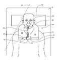
- FIG. 1is a schematic top view of a patient, lying down, wearing the wearable CPAP unit;
- FIG. 3is an isometric view showing the orientation, relationship and position of various elements of the wearable CPAP unit
- FIG. 4is an isometric view of the impeller diffuser inlet and outlet portion of the device
- FIG. 5is a schematic top view of an alternate embodiment
- FIG. 6is a view of an interface particularly suited for use in the system.
- FIG. 7is an enlarged perspective view of one of the cannulas of the interface of FIG. 6 .
- FIG. 1shows the general configuration of a portable self-contained wearable CPAP vest 14 being worn by a patient or user 10 who is depicted in a supine position on a bed 11 with a pillow 16 under his head.
- the vest 14has a rounded neck portion or collar 30 positioned at the nape of the neck of the user.
- the collar 30connects with and flares out onto a first panel 26 and a second panel 28 that lie over the chest of the user 10 .
- Each panel 26 , 28has a lower edge 29 , 31 , respectively, and an inner edge 33 , 35 , respectively.
- the optimal size and shape of the collar 30 and the panels 26 and 28will depend upon the stature of the user 10 .
- the cross-section of the collar 30 proximate the neck of the userbe of reduced cross-section or diameter, and have a contoured shape such that it fits within the nape of the neck and does not act as a “pillow” or interfere with the patient's actual pillow 16 when the patient 10 reclines.
- FIG. 2which shows a supine patient 10 and an associated plane 32 defined by and extending from the back of the head to the shoulder blades. It is preferred to have the collar 30 not completely fill the nape of the neck so that the collar 30 does not touch or extend beyond the plane 32 toward the bed 11 .
- the exterior edges of the panel portions 26 and 28lie within the shoulder-width of the patient and within the head-to-shoulder plane identified by reference numeral 34 in FIG. 1 . It has been found that when these several conditions are met the patient 10 may rest on his side and roll over in his sleep with the head and shoulders in a natural posture. When appropriately sized, the collar 30 and panels 26 , 28 do not interfere with the comfort of the patient. These geometric and dimensional attributes define the shape of a vest 14 that may be worn unobtrusively during sleep. It has been found that these design attributes associated with these cross-sectional areas and bulk of the panels are designed not to interfere with patient comfort.
- connection hose 22couples the vest 14 to a user interface or mask 24 .
- the mask 24serves as an air delivery device and other interfaces may be readily substituted within the context of the invention.
- the proximal end of the hose 22couples to one panel portion 26 of the vest 14 at an outlet 20 .
- air entering the vest via inlet 18is pressurized within the vest 14 and transferred to the hose 22 and thence to the mask 24 or other interface structure.
- the distal ends of the panels 26 and 28may be connected together by a clasp 27 or other device to keep the vest oriented on the patient.
- the panelsmay be fixed to the clothing of the user 10 by structures (not shown) to maintain orientation of the panels 26 , 28 with respect to the chest of the user.
- FIG. 3shows a blower unit housing 40 in panel 26 of the vest 14 .
- This blower unit housing 40contains within it, a motor/impeller and associated diffuser scroll unit 42 .
- Many mechanical features and structures and relationships further described,have been found to be effective in suppressing noise generated by the pressurization of air within the vest 14 . These features are described in connection with FIG. 4 .
- the blower unit housing 40 and motor/impeller unithave together several attributes that will, in combination, produce a very quiet blower that is believed to be an important characteristic for acceptance of the vest by the user. It is advantageous for the motor impeller unit to use very low power to allow portable battery operation and to prevent excessive heat build up in the device or in air exiting the device.
- the second panel 28 of the vest 14contains a battery pack 36 coupled to an electronic motor control unit 38 .
- the battery pack 36being compact in nature and has sufficient capacity to operate the vest 14 for periods of time approximating ten hours or so.
- Buttons (not shown) on the control unit 38are exteriorized for use by the patient 10 .
- the control unit 38carries motor control functions (e.g. an on/off switch) and a charging receptacle or jack to permit the patient 10 to recharge the battery pack 36 .
- the partitioning of the battery pack 36 , control unit 38 and blower unit housing 40is intended to equalize the weight of the side panels 26 and 28 to make them roughly equivalent, which helps maintain the vest 14 in position on the wearer or user 10 . To achieve this result, it is permissible to reorganize the distribution of weight throughout the vest and it is anticipated that the battery pack may be split or placed elsewhere in the vest 10 . Electrical connections, not shown to simplify the figure, are buried within the foam of the vest 10 and connect the control unit 38 with the battery pack 36 and the motor within the blower unit housing 40 .
- a short hose 22couples the outlet 20 to a user interface or distribution device, such as a mask 24 (shown in FIG. 1 ) or nasal cannula (not shown) to provide CPAP flow to the patient's airways.
- a short light hose 22produces less pull on the mask 24 or interface worn by the patient promoting less movement of the mask on the patient face with subsequently a better seal. Also, not being connected to a bed-side CPAP unit provides freedom of movement for the patient.
- air inlet 18 for the blower unit housing 40near the bottom of one side, or adjacent one panel, of the vest 14 as seen with reference to inlet 18 on FIG. 1 and FIG. 2 .
- This locationdirects noise away from patient and bed partner and is generally unobstructed during sleep for most patients.
- Other alternative locationsare contemplated including connections on the upper surface of the collar or panel away from the patient.
- the blower unit housing 40is shown with a cross-section taken at line 4 — 4 in FIG. 3 .
- This figuredepicts the motor/impeller and associated scroll housing 42 contained within the blower housing 40 .
- the clamshell housing 40defines a labyrinthine air path between an inlet 18 to the motor/impeller unit inlet annulus 54 .
- the motor/impeller and scroll unit 42accelerate the airflow and increase the kinetic energy in the airflow.
- the diffuser scrollis formed integrally with the motor and it serves to convert the kinetic energy to a static pressure delivered to the outlet 20 that is also the end of the “scroll” passage shown as the short tube 21 .
- DC brushless motor elementsare adjacent to the impeller wheel 55 .
- the impeller wheel 55is supported cantilever fashion on an axle by two bearings 53 and 57 , each of which is below the impeller 55 .
- the motor elements, impeller 55 , and diffuser scroll 42form an independent mechanical unit that is isolated from the blower housing 40 . It may be suspended by or mounted on a foam pad or a set of rubber standoffs (not shown). Thus, the motor/impeller elements lie within a “cocoon” like chamber 58 and are mechanically isolated from the remainder of the blower unit 40 .
- the preferred constructionis a clamshell with a top 44 or lid fitting on top of a lower 46 clamshell portion.
- the housingis lined with a foam and it has a complex passage diverting air flowing along path 60 through two ninety degree turns depicted in the figure by flow arrows 62 and 64 to turn the airflow through a tortuous path to the inlet annulus 54 of the impeller 55 .
- flow arrows 62 and 64depicted in the figure by flow arrows 62 and 64 to turn the airflow through a tortuous path to the inlet annulus 54 of the impeller 55 .
- These baffleshelp suppress the radiation or conduction of noise emanating from the motor/impeller.
- the vest 14houses and supports operational components such as the blower unit housing 40 with motor impeller and scroll unit 42 , the battery pack 36 and the control unit 38 .
- the vest 14supports the hose 22 that carries air from the operational components to the user interface 24 .
- One of the advantages achieved by this arrangement over the conventional bedside CPAP machineis that forces that tend to pull a mask away from a patient's nose and mouth are significantly reduced.
- the “head gear” required to hold the interface to the patient's faceneed not be elaborate.
- the embodiment of FIG. 1lacks the conventional straps used to secure the interface to the face.
- the vestis very stable in position on the patient and most patient motion does not result in significant forces applied to the mask or interface. If the compliant tube 22 is biased toward the face, then a force is generated to retain the interface on the face.
- FIG. 5depicts an alternative embodiment where a user interface 105 connects via a vest 114 to a traditional bedside CPAP unit 115 .
- the vest 114supports a hose section 120 between the vest 114 and the CPAP unit 115 .
- the vest 114supports a hose section 125 between the vest 114 and the user interface 105 .
- Hose sections 120 and 125are in fluid communication, and may be continuous or may be in discrete sections, to allow air from the CPAP unit to pass to the user interface 105 .
- the vestmay include a conduit 126 passing from the inside edge 130 of one panel 131 to the outside edge 132 of the panel 131 , with hose section 125 connected to the inside edge and hose section 120 connected to the outside edge.
- the vest 114bears and disperses to the patient's torso the mechanical forces transmitted by the hose section 120 , so that those forces are not transmitted to the hose section 125 . In this manner, the user interface 105 is de-coupled from these forces and therefore the interface is held in place without significant head gear.
- the FIG. 5 embodimentprovides no straps to hold the mask in place.
- the vest 114may include operational components, as described above with respect to the FIG. 1 embodiment, and allow the user to selectively couple the hose section 125 to the outlet of the in-vest blower or to the outlet of a conventional bedside CPAP unit, as desired.
- FIG. 6shows a nasal mask or interface 200 that uses only very “light” retention straps 210 to keep the interface 200 on the face of the user.
- the mask 200includes two nasal cannulas 220 , 221 which, in use, are inserted into the patient's nostrils. These cannulas or portals 220 , 221 are designed to experience minimal lateral movement and are stabilized by the mask 200 fitted over the patient's nose.
- the mask 200is sized to cover the patient's nose, but not the mouth.
- FIG. 7illustrates one of the cannulas 220 .
Landscapes
- Health & Medical Sciences (AREA)
- Emergency Medicine (AREA)
- Pulmonology (AREA)
- Engineering & Computer Science (AREA)
- Anesthesiology (AREA)
- Biomedical Technology (AREA)
- Heart & Thoracic Surgery (AREA)
- Hematology (AREA)
- Life Sciences & Earth Sciences (AREA)
- Animal Behavior & Ethology (AREA)
- General Health & Medical Sciences (AREA)
- Public Health (AREA)
- Veterinary Medicine (AREA)
- Professional, Industrial, Or Sporting Protective Garments (AREA)
- Respiratory Apparatuses And Protective Means (AREA)
Abstract
Description
Claims (2)
Priority Applications (2)
| Application Number | Priority Date | Filing Date | Title |
|---|---|---|---|
| US11/128,552US7195014B2 (en) | 2005-03-22 | 2005-05-13 | Portable continuous positive airway pressure system |
| US11/635,338US20070089743A1 (en) | 2005-03-22 | 2006-12-07 | Portable continuous positive airway pressure system |
Applications Claiming Priority (2)
| Application Number | Priority Date | Filing Date | Title |
|---|---|---|---|
| US66410805P | 2005-03-22 | 2005-03-22 | |
| US11/128,552US7195014B2 (en) | 2005-03-22 | 2005-05-13 | Portable continuous positive airway pressure system |
Related Child Applications (1)
| Application Number | Title | Priority Date | Filing Date |
|---|---|---|---|
| US11/635,338ContinuationUS20070089743A1 (en) | 2005-03-22 | 2006-12-07 | Portable continuous positive airway pressure system |
Publications (2)
| Publication Number | Publication Date |
|---|---|
| US20060213516A1 US20060213516A1 (en) | 2006-09-28 |
| US7195014B2true US7195014B2 (en) | 2007-03-27 |
Family
ID=37033956
Family Applications (2)
| Application Number | Title | Priority Date | Filing Date |
|---|---|---|---|
| US11/128,552Expired - Fee RelatedUS7195014B2 (en) | 2005-03-22 | 2005-05-13 | Portable continuous positive airway pressure system |
| US11/635,338AbandonedUS20070089743A1 (en) | 2005-03-22 | 2006-12-07 | Portable continuous positive airway pressure system |
Family Applications After (1)
| Application Number | Title | Priority Date | Filing Date |
|---|---|---|---|
| US11/635,338AbandonedUS20070089743A1 (en) | 2005-03-22 | 2006-12-07 | Portable continuous positive airway pressure system |
Country Status (1)
| Country | Link |
|---|---|
| US (2) | US7195014B2 (en) |
Cited By (25)
| Publication number | Priority date | Publication date | Assignee | Title |
|---|---|---|---|---|
| US20070163600A1 (en)* | 2006-01-11 | 2007-07-19 | Leslie Hoffman | User interface and head gear for a continuous positive airway pressure device |
| USD578650S1 (en) | 2007-09-17 | 2008-10-14 | Adams Phillip M | Positive airway pressure apparatus |
| WO2008131202A1 (en)* | 2007-04-20 | 2008-10-30 | Cardinal Health 212, Llc | Acoustic attenuation chamber |
| USD580061S1 (en) | 2007-09-17 | 2008-11-04 | Adams Phillip M | Positive airway pressure apparatus |
| USD580062S1 (en) | 2007-09-17 | 2008-11-04 | Adams Phillip M | Positive airway pressure apparatus |
| USD580060S1 (en) | 2007-09-17 | 2008-11-04 | Adams Phillip M | Positive airway pressure apparatus |
| USD582554S1 (en) | 2007-09-17 | 2008-12-09 | Adams Philip M | Positive airway pressure apparatus |
| USD583059S1 (en) | 2007-09-17 | 2008-12-16 | Adams Phillip M | Positive airway pressure apparatus |
| US20090039210A1 (en)* | 2007-08-10 | 2009-02-12 | Yates Steven T | CPAP Hose Support System |
| US20090071480A1 (en)* | 2007-09-17 | 2009-03-19 | Adams Phillip M | Compact continuous positive airway pressure apparatus and method |
| US7516743B2 (en)* | 2006-04-20 | 2009-04-14 | Viasys Sleep Systems, Llc | Continuous positive airway pressure device and configuration for employing same |
| USD595529S1 (en) | 2008-05-28 | 2009-07-07 | Todd Deetsch | Pillow insert |
| USD595531S1 (en) | 2008-05-28 | 2009-07-07 | Todd Deetsch | Pillow with cross straps |
| USD595530S1 (en) | 2008-05-28 | 2009-07-07 | Todd Deetsch | Pillow with X straps |
| US20100170513A1 (en)* | 2009-01-08 | 2010-07-08 | Bowditch Nathaniel L | Self-contained, intermittent positive airway pressure systems and methods for treating sleep apnea, snoring, and other respiratory disorders |
| WO2011062633A1 (en)* | 2009-11-19 | 2011-05-26 | Resmed Motor Technologies, Inc. | Blower |
| US20120174922A1 (en)* | 2009-07-17 | 2012-07-12 | Alexander Virr | Respirator |
| US8327846B2 (en) | 2011-02-08 | 2012-12-11 | Hancock Medical, Inc. | Positive airway pressure system with head position control |
| US8631791B2 (en) | 2006-04-10 | 2014-01-21 | Somnetics Global Pte. Ltd. | Apparatus and methods for administration of positive airway pressure therapies |
| US9084859B2 (en) | 2011-03-14 | 2015-07-21 | Sleepnea Llc | Energy-harvesting respiratory method and device |
| USD776802S1 (en) | 2015-03-06 | 2017-01-17 | Hancock Medical, Inc. | Positive airway pressure system console |
| US10314989B2 (en) | 2013-01-28 | 2019-06-11 | Hancock Medical, Inc. | Position control devices and methods for use with positive airway pressure systems |
| US10632009B2 (en) | 2016-05-19 | 2020-04-28 | Hancock Medical, Inc. | Positional obstructive sleep apnea detection system |
| USD899816S1 (en) | 2018-08-20 | 2020-10-27 | Todd Douglas Deetsch | Pillow for a person's head |
| US10881829B2 (en) | 2014-08-18 | 2021-01-05 | Resmed Inc. | Portable pap device with humidification |
Families Citing this family (41)
| Publication number | Priority date | Publication date | Assignee | Title |
|---|---|---|---|---|
| US7588033B2 (en) | 2003-06-18 | 2009-09-15 | Breathe Technologies, Inc. | Methods, systems and devices for improving ventilation in a lung area |
| CN1905917B (en) | 2003-08-18 | 2011-08-03 | 门罗生命公司 | Method and device for non-invasive ventilation with nasal interface |
| EP1675639A4 (en)* | 2003-09-25 | 2009-12-02 | Resmed Ltd | Ventilator mask and system |
| EP3936180B1 (en) | 2004-04-02 | 2023-11-29 | Fisher & Paykel Healthcare Limited | Breathing assistance apparatus |
| JP2009508645A (en) | 2005-09-20 | 2009-03-05 | ルッツ フレイテッグ, | System, method and apparatus for assisting patient breathing |
| US8427020B2 (en)* | 2006-04-20 | 2013-04-23 | Carefusion 212, Llc | Blower assembly with integral injection molded suspension mount |
| JP5191005B2 (en) | 2006-05-18 | 2013-04-24 | ブリーズ テクノロジーズ, インコーポレイテッド | Method and device for tracheostomy |
| DE202007019687U1 (en) | 2006-07-14 | 2015-07-14 | Fisher & Paykel Healthcare Ltd. | Respiratory support device |
| EP2068992B1 (en) | 2006-08-03 | 2016-10-05 | Breathe Technologies, Inc. | Devices for minimally invasive respiratory support |
| DE112008000204T5 (en)* | 2007-01-19 | 2009-12-17 | Banyan Licensing, LLC, Fort Lauderdale | Pillows and procedures for use in respiratory assisted respiratory masks |
| US20080178879A1 (en)* | 2007-01-29 | 2008-07-31 | Braebon Medical Corporation | Impeller for a wearable positive airway pressure device |
| US20080216831A1 (en)* | 2007-03-08 | 2008-09-11 | Mcginnis William J | Standalone cpap device and method of using |
| WO2008144589A1 (en) | 2007-05-18 | 2008-11-27 | Breathe Technologies, Inc. | Methods and devices for sensing respiration and providing ventilation therapy |
| EP2200686A4 (en) | 2007-09-26 | 2017-11-01 | Breathe Technologies, Inc. | Methods and devices for providing inspiratory and expiratory flow relief during ventilation therapy |
| EP2203206A4 (en) | 2007-09-26 | 2017-12-06 | Breathe Technologies, Inc. | Methods and devices for treating sleep apnea |
| AU2008319519A1 (en)* | 2007-10-30 | 2009-05-07 | Fisher & Paykel Healthcare Limited | Fan unit with bypass vent holes |
| US8776793B2 (en) | 2008-04-18 | 2014-07-15 | Breathe Technologies, Inc. | Methods and devices for sensing respiration and controlling ventilator functions |
| WO2009129506A1 (en) | 2008-04-18 | 2009-10-22 | Breathe Technologies, Inc. | Methods and devices for sensing respiration and controlling ventilator functions |
| US10792451B2 (en) | 2008-05-12 | 2020-10-06 | Fisher & Paykel Healthcare Limited | Patient interface and aspects thereof |
| WO2010003064A1 (en)* | 2008-07-02 | 2010-01-07 | Aeiomed, Inc. | Methods for battery power management of positive airway pressure apparatus |
| US11660413B2 (en) | 2008-07-18 | 2023-05-30 | Fisher & Paykel Healthcare Limited | Breathing assistance apparatus |
| CN102196837B (en) | 2008-08-22 | 2015-09-09 | 呼吸科技公司 | Methods and devices for providing mechanical ventilation utilizing an open airway interface |
| US10252020B2 (en) | 2008-10-01 | 2019-04-09 | Breathe Technologies, Inc. | Ventilator with biofeedback monitoring and control for improving patient activity and health |
| US9132250B2 (en) | 2009-09-03 | 2015-09-15 | Breathe Technologies, Inc. | Methods, systems and devices for non-invasive ventilation including a non-sealing ventilation interface with an entrainment port and/or pressure feature |
| CN111420208B (en) | 2009-04-02 | 2023-07-04 | 呼吸科技公司 | Methods, systems and devices for non-invasive open ventilation using a gas delivery nozzle within an outer tube |
| US9962512B2 (en) | 2009-04-02 | 2018-05-08 | Breathe Technologies, Inc. | Methods, systems and devices for non-invasive ventilation including a non-sealing ventilation interface with a free space nozzle feature |
| CN111905220B (en)* | 2009-05-12 | 2024-01-09 | 费雪派克医疗保健有限公司 | Patient interface and aspects thereof |
| US8931481B2 (en)* | 2009-06-04 | 2015-01-13 | Redmed Limited | Flow generator chassis assembly with suspension seal |
| WO2011029074A1 (en) | 2009-09-03 | 2011-03-10 | Breathe Technologies, Inc. | Methods, systems and devices for non-invasive ventilation including a non-sealing ventilation interface with an entrainment port and/or pressure feature |
| NO20093496A1 (en)* | 2009-12-09 | 2011-06-06 | E Innovation As | Device for breathing air unit |
| CA2807416C (en) | 2010-08-16 | 2019-02-19 | Breathe Technologies, Inc. | Methods, systems and devices using lox to provide ventilatory support |
| US9616190B2 (en) | 2010-08-27 | 2017-04-11 | Resmed Limited | PAP system |
| CA2811423C (en) | 2010-09-30 | 2019-03-12 | Breathe Technologies, Inc. | Methods, systems and devices for humidifying a respiratory tract |
| EP2624903B1 (en) | 2010-10-08 | 2018-05-16 | Fisher & Paykel Healthcare Limited | Breathing assistance apparatus |
| EP4169558A1 (en)* | 2011-06-21 | 2023-04-26 | ResMed Pty Ltd | Pap system |
| CN119345556A (en) | 2012-03-06 | 2025-01-24 | 瑞思迈发动机及马达技术股份有限公司 | Traffic Generator |
| US20140014110A1 (en)* | 2012-07-16 | 2014-01-16 | Phillip M. Adams | Remotely controlled positive airway-pressure apparatus and method |
| WO2014097518A1 (en)* | 2012-12-17 | 2014-06-26 | 日本電産コパル電子株式会社 | Cpap device |
| US10792449B2 (en) | 2017-10-03 | 2020-10-06 | Breathe Technologies, Inc. | Patient interface with integrated jet pump |
| TWI790597B (en) | 2020-05-21 | 2023-01-21 | 佳音醫療器材股份有限公司 | Device for alleviating obstructive sleep apnea |
| TWM630465U (en)* | 2022-04-28 | 2022-08-01 | 高昌生醫股份有限公司 | mobile respirator |
Citations (2)
| Publication number | Priority date | Publication date | Assignee | Title |
|---|---|---|---|---|
| US4019508A (en)* | 1976-05-21 | 1977-04-26 | Research Development Systems, Inc. | Wearable, self-contained fully mobile personal breathing apparatus for surgeons and operating room personnel |
| USH1360H (en)* | 1991-04-24 | 1994-10-04 | The United States Of America, As Represented By The Secretary Of The Army | Lightweight protective gas mask and hood |
Family Cites Families (16)
| Publication number | Priority date | Publication date | Assignee | Title |
|---|---|---|---|---|
| US4379656A (en)* | 1977-07-14 | 1983-04-12 | Darling Phillip H | Buoyancy control valve for scuba diving vests |
| US4430995A (en)* | 1981-05-29 | 1984-02-14 | Hilton Joseph R | Power assisted air-purifying respirators |
| US4800984A (en)* | 1987-04-24 | 1989-01-31 | Cartex Corporation | Acoustical barrier for vehicles |
| FR2673380B1 (en)* | 1991-02-28 | 1993-06-18 | Intertechnique Sa | PERSONAL RESPIRATORY PROTECTION EQUIPMENT. |
| US5511542A (en)* | 1994-03-31 | 1996-04-30 | Westinghouse Electric Corporation | Lox breathing system with gas permeable-liquid impermeable heat exchange and delivery hose |
| US5490501A (en)* | 1994-05-16 | 1996-02-13 | Crowley; Thomas J. | Avalanche victim's air-from-snow breathing device |
| US5529061A (en)* | 1995-01-03 | 1996-06-25 | Stan A. Sanders | Jacket supported pressurized 02 coil |
| CA2259128A1 (en)* | 1997-02-18 | 1998-08-18 | David J. Korman | Personal air filtering and delivery systems |
| US6039043A (en)* | 1998-01-27 | 2000-03-21 | Johnson Worldwide Associates, Inc. | Underwater air supply system |
| US20030054360A1 (en)* | 1999-01-19 | 2003-03-20 | Larry Gold | Method and apparatus for the automated generation of nucleic acid ligands |
| US6615831B1 (en)* | 1999-07-02 | 2003-09-09 | Respironics, Inc. | Pressure support system and method and a pressure control valve for use in such system and method |
| US6340025B1 (en)* | 1999-10-04 | 2002-01-22 | American Biosystems, Inc. | Airway treatment apparatus with airflow enhancement |
| US6513522B1 (en)* | 2000-06-13 | 2003-02-04 | Mallinckrodt Inc. | Wearable storage system for pressurized fluids |
| AUPR315401A0 (en)* | 2001-02-16 | 2001-03-15 | Resmed Limited | An apparatus for supplying clean breathable gas |
| US7448383B2 (en)* | 2002-03-08 | 2008-11-11 | Kaerys, S.A. | Air assistance apparatus providing fast rise and fall of pressure within one patient's breath |
| AU2003903139A0 (en)* | 2003-06-20 | 2003-07-03 | Resmed Limited | Breathable gas apparatus with humidifier |
- 2005
- 2005-05-13USUS11/128,552patent/US7195014B2/ennot_activeExpired - Fee Related
- 2006
- 2006-12-07USUS11/635,338patent/US20070089743A1/ennot_activeAbandoned
Patent Citations (2)
| Publication number | Priority date | Publication date | Assignee | Title |
|---|---|---|---|---|
| US4019508A (en)* | 1976-05-21 | 1977-04-26 | Research Development Systems, Inc. | Wearable, self-contained fully mobile personal breathing apparatus for surgeons and operating room personnel |
| USH1360H (en)* | 1991-04-24 | 1994-10-04 | The United States Of America, As Represented By The Secretary Of The Army | Lightweight protective gas mask and hood |
Non-Patent Citations (1)
| Title |
|---|
| Halberstadt, Jerry, Battery Operation of CPAP Devices for Sleep Apnea Treatment, Part 2: A battery backup system for use with CPAP treatment, New Technology Publishing, Inc., http://www.newtechpub.com/sleep/magazines/psnews/power02.html. |
Cited By (46)
| Publication number | Priority date | Publication date | Assignee | Title |
|---|---|---|---|---|
| US20070163600A1 (en)* | 2006-01-11 | 2007-07-19 | Leslie Hoffman | User interface and head gear for a continuous positive airway pressure device |
| US8631791B2 (en) | 2006-04-10 | 2014-01-21 | Somnetics Global Pte. Ltd. | Apparatus and methods for administration of positive airway pressure therapies |
| US9694153B2 (en) | 2006-04-10 | 2017-07-04 | Somnetics Global Pte. Ltd. | Apparatus and methods for administration of positive airway pressure therapies |
| US7516743B2 (en)* | 2006-04-20 | 2009-04-14 | Viasys Sleep Systems, Llc | Continuous positive airway pressure device and configuration for employing same |
| US7789194B2 (en) | 2007-04-20 | 2010-09-07 | Cardinal Health 212, Inc. | Acoustic attenuation chamber |
| WO2008131202A1 (en)* | 2007-04-20 | 2008-10-30 | Cardinal Health 212, Llc | Acoustic attenuation chamber |
| US20090039210A1 (en)* | 2007-08-10 | 2009-02-12 | Yates Steven T | CPAP Hose Support System |
| US20110203592A1 (en)* | 2007-09-17 | 2011-08-25 | Adams Phillip M | Compact continuous positive airway pressure apparatus and method |
| USD580060S1 (en) | 2007-09-17 | 2008-11-04 | Adams Phillip M | Positive airway pressure apparatus |
| US20090071480A1 (en)* | 2007-09-17 | 2009-03-19 | Adams Phillip M | Compact continuous positive airway pressure apparatus and method |
| USD580062S1 (en) | 2007-09-17 | 2008-11-04 | Adams Phillip M | Positive airway pressure apparatus |
| US8353290B2 (en)* | 2007-09-17 | 2013-01-15 | Adams Phillip M | Compact continuous positive airway pressure apparatus and method |
| USD578650S1 (en) | 2007-09-17 | 2008-10-14 | Adams Phillip M | Positive airway pressure apparatus |
| US9782552B1 (en) | 2007-09-17 | 2017-10-10 | Phillip M. Adams | Compact continuous positive airway pressure apparatus and method |
| USD580061S1 (en) | 2007-09-17 | 2008-11-04 | Adams Phillip M | Positive airway pressure apparatus |
| USD582554S1 (en) | 2007-09-17 | 2008-12-09 | Adams Philip M | Positive airway pressure apparatus |
| US9044561B2 (en) | 2007-09-17 | 2015-06-02 | Phillip M. Adams | Compact continuous positive airway pressure apparatus and method |
| USD583059S1 (en) | 2007-09-17 | 2008-12-16 | Adams Phillip M | Positive airway pressure apparatus |
| US8011362B2 (en) | 2007-09-17 | 2011-09-06 | Adams Phillip M | Compact continuous positive airway pressure apparatus and method |
| USD595530S1 (en) | 2008-05-28 | 2009-07-07 | Todd Deetsch | Pillow with X straps |
| USD595531S1 (en) | 2008-05-28 | 2009-07-07 | Todd Deetsch | Pillow with cross straps |
| USD595529S1 (en) | 2008-05-28 | 2009-07-07 | Todd Deetsch | Pillow insert |
| US8517017B2 (en) | 2009-01-08 | 2013-08-27 | Hancock Medical, Inc. | Self-contained, intermittent positive airway pressure systems and methods for treating sleep apnea, snoring, and other respiratory disorders |
| US10112025B2 (en) | 2009-01-08 | 2018-10-30 | Hancock Medical, Inc. | Self-contained, intermittent positive airway pressure systems and methods for treating sleep apnea, snoring, and other respiratory disorders |
| US20100170513A1 (en)* | 2009-01-08 | 2010-07-08 | Bowditch Nathaniel L | Self-contained, intermittent positive airway pressure systems and methods for treating sleep apnea, snoring, and other respiratory disorders |
| US9248248B2 (en)* | 2009-07-17 | 2016-02-02 | Paftec Technologies Pty Ltd | Respirator |
| US20120174922A1 (en)* | 2009-07-17 | 2012-07-12 | Alexander Virr | Respirator |
| US10940280B2 (en) | 2009-11-19 | 2021-03-09 | Resmed Motor Technologies Inc. | Blower |
| US20120199129A1 (en)* | 2009-11-19 | 2012-08-09 | Resmed Motor Technologies, Inc. | Blower |
| US8973576B2 (en)* | 2009-11-19 | 2015-03-10 | Resmed Motor Technologies Inc | Blower |
| WO2011062633A1 (en)* | 2009-11-19 | 2011-05-26 | Resmed Motor Technologies, Inc. | Blower |
| US9662463B2 (en) | 2009-11-19 | 2017-05-30 | Resmed Motor Technologies Inc. | Blower |
| US8336546B2 (en) | 2011-02-08 | 2012-12-25 | Hancock Medical, Inc. | Positive airway pressure system with head control |
| US8327846B2 (en) | 2011-02-08 | 2012-12-11 | Hancock Medical, Inc. | Positive airway pressure system with head position control |
| US9180267B2 (en) | 2011-02-08 | 2015-11-10 | Hancock Medical, Inc. | Positive airway pressure system with head position control |
| US8919344B2 (en) | 2011-02-08 | 2014-12-30 | Hancock Medical, Inc. | Positive airway pressure system with head position control |
| US8925546B2 (en) | 2011-02-08 | 2015-01-06 | Hancock Medical, Inc. | Positive airway pressure system with head position control |
| US9084859B2 (en) | 2011-03-14 | 2015-07-21 | Sleepnea Llc | Energy-harvesting respiratory method and device |
| US10314989B2 (en) | 2013-01-28 | 2019-06-11 | Hancock Medical, Inc. | Position control devices and methods for use with positive airway pressure systems |
| US10881829B2 (en) | 2014-08-18 | 2021-01-05 | Resmed Inc. | Portable pap device with humidification |
| US11813385B2 (en) | 2014-08-18 | 2023-11-14 | Resmed Inc. | Portable pap device with humidification |
| US12233214B2 (en) | 2014-08-18 | 2025-02-25 | Resmed Inc. | Portable PAP device with humidification |
| USD776802S1 (en) | 2015-03-06 | 2017-01-17 | Hancock Medical, Inc. | Positive airway pressure system console |
| US10632009B2 (en) | 2016-05-19 | 2020-04-28 | Hancock Medical, Inc. | Positional obstructive sleep apnea detection system |
| US11660228B2 (en) | 2016-05-19 | 2023-05-30 | Oura Health Oy | Positional obstructive sleep apnea detection system |
| USD899816S1 (en) | 2018-08-20 | 2020-10-27 | Todd Douglas Deetsch | Pillow for a person's head |
Also Published As
| Publication number | Publication date |
|---|---|
| US20070089743A1 (en) | 2007-04-26 |
| US20060213516A1 (en) | 2006-09-28 |
Similar Documents
| Publication | Publication Date | Title |
|---|---|---|
| US7195014B2 (en) | Portable continuous positive airway pressure system | |
| JP5295949B2 (en) | Apparatus and method for the treatment of positive airway pressure therapy | |
| US10549057B2 (en) | CPAP mask and system | |
| US7516743B2 (en) | Continuous positive airway pressure device and configuration for employing same | |
| CN102695536B (en) | Single-Stage Axisymmetric Blowers and Portable Ventilators | |
| JP6161564B2 (en) | Breathing apparatus | |
| JP7032310B2 (en) | A device that provides airflow to the user | |
| US20070000493A1 (en) | Apparatus for maintaining airway patency | |
| KR20120089731A (en) | Integrated positive airway pressure apparatus |
Legal Events
| Date | Code | Title | Description |
|---|---|---|---|
| AS | Assignment | Owner name:HOFFMAN LABORATORIES, LLC, CALIFORNIA Free format text:ASSIGNMENT OF ASSIGNORS INTEREST;ASSIGNOR:HOFFMAN, LESLIE;REEL/FRAME:016868/0428 Effective date:20050726 | |
| AS | Assignment | Owner name:VIASYS SLEEP SOLUTIONS LLC, PENNSYLVANIA Free format text:ASSIGNMENT OF ASSIGNORS INTEREST;ASSIGNOR:HOFFMAN, LESLIE;REEL/FRAME:018555/0363 Effective date:20061109 | |
| STCF | Information on status: patent grant | Free format text:PATENTED CASE | |
| AS | Assignment | Owner name:VIASYS SLEEP SYSTEMS LLC, PENNSYLVANIA Free format text:CHANGE OF NAME;ASSIGNOR:VIASYS SLEEP SOLUTIONS LLC;REEL/FRAME:019217/0583 Effective date:20070104 | |
| FEPP | Fee payment procedure | Free format text:PAYOR NUMBER ASSIGNED (ORIGINAL EVENT CODE: ASPN); ENTITY STATUS OF PATENT OWNER: LARGE ENTITY | |
| FPAY | Fee payment | Year of fee payment:4 | |
| AS | Assignment | Owner name:CARDINAL HEALTH 212, LLC, CALIFORNIA Free format text:CHANGE OF NAME;ASSIGNOR:VIASYS SLEEP SYSTEMS, LLC;REEL/FRAME:025340/0627 Effective date:20071016 | |
| AS | Assignment | Owner name:CAREFUSION 212, LLC, CALIFORNIA Free format text:CHANGE OF NAME;ASSIGNOR:CARDINAL HEALTH 212, LLC;REEL/FRAME:025685/0415 Effective date:20090729 | |
| FPAY | Fee payment | Year of fee payment:8 | |
| FEPP | Fee payment procedure | Free format text:MAINTENANCE FEE REMINDER MAILED (ORIGINAL EVENT CODE: REM.); ENTITY STATUS OF PATENT OWNER: LARGE ENTITY | |
| LAPS | Lapse for failure to pay maintenance fees | Free format text:PATENT EXPIRED FOR FAILURE TO PAY MAINTENANCE FEES (ORIGINAL EVENT CODE: EXP.); ENTITY STATUS OF PATENT OWNER: LARGE ENTITY | |
| STCH | Information on status: patent discontinuation | Free format text:PATENT EXPIRED DUE TO NONPAYMENT OF MAINTENANCE FEES UNDER 37 CFR 1.362 | |
| FP | Lapsed due to failure to pay maintenance fee | Effective date:20190327 |