US7194550B1 - Providing a single hop communication path between a storage device and a network switch - Google Patents
Providing a single hop communication path between a storage device and a network switchDownload PDFInfo
- Publication number
- US7194550B1 US7194550B1US09/944,425US94442501AUS7194550B1US 7194550 B1US7194550 B1US 7194550B1US 94442501 AUS94442501 AUS 94442501AUS 7194550 B1US7194550 B1US 7194550B1
- Authority
- US
- United States
- Prior art keywords
- communication protocol
- incoming packet
- tcp
- switch
- networking device
- Prior art date
- Legal status (The legal status is an assumption and is not a legal conclusion. Google has not performed a legal analysis and makes no representation as to the accuracy of the status listed.)
- Expired - Fee Related, expires
Links
- 238000004891communicationMethods0.000titleclaimsdescription224
- 230000006855networkingEffects0.000claimsabstractdescription155
- 238000006243chemical reactionMethods0.000claimsabstractdescription41
- 238000012545processingMethods0.000claimsdescription49
- 238000000034methodMethods0.000claimsdescription24
- 230000004044responseEffects0.000claimsdescription16
- 230000008569processEffects0.000claimsdescription3
- 238000012546transferMethods0.000abstractdescription33
- 238000010586diagramMethods0.000description14
- 230000006978adaptationEffects0.000description4
- 235000008694Humulus lupulusNutrition0.000description3
- 239000000835fiberSubstances0.000description3
- 230000003287optical effectEffects0.000description3
- 239000000872bufferSubstances0.000description2
- 238000007726management methodMethods0.000description2
- 238000013507mappingMethods0.000description2
- 230000037361pathwayEffects0.000description2
- 101001022148Homo sapiens FurinProteins0.000description1
- 101000701936Homo sapiens Signal peptidase complex subunit 1Proteins0.000description1
- 102100030313Signal peptidase complex subunit 1Human genes0.000description1
- 238000013475authorizationMethods0.000description1
- 230000005540biological transmissionEffects0.000description1
- 238000005538encapsulationMethods0.000description1
- 239000004744fabricSubstances0.000description1
- 238000013467fragmentationMethods0.000description1
- 238000006062fragmentation reactionMethods0.000description1
- 238000009432framingMethods0.000description1
- 230000006870functionEffects0.000description1
- 239000003999initiatorSubstances0.000description1
- 238000012986modificationMethods0.000description1
- 230000004048modificationEffects0.000description1
- 238000011084recoveryMethods0.000description1
- 230000003068static effectEffects0.000description1
Images


Classifications
- H—ELECTRICITY
- H04—ELECTRIC COMMUNICATION TECHNIQUE
- H04L—TRANSMISSION OF DIGITAL INFORMATION, e.g. TELEGRAPHIC COMMUNICATION
- H04L67/00—Network arrangements or protocols for supporting network services or applications
- H04L67/01—Protocols
- H04L67/10—Protocols in which an application is distributed across nodes in the network
- H04L67/1097—Protocols in which an application is distributed across nodes in the network for distributed storage of data in networks, e.g. transport arrangements for network file system [NFS], storage area networks [SAN] or network attached storage [NAS]
- H—ELECTRICITY
- H04—ELECTRIC COMMUNICATION TECHNIQUE
- H04L—TRANSMISSION OF DIGITAL INFORMATION, e.g. TELEGRAPHIC COMMUNICATION
- H04L69/00—Network arrangements, protocols or services independent of the application payload and not provided for in the other groups of this subclass
- H04L69/08—Protocols for interworking; Protocol conversion
Definitions
- This inventionrelates generally to electronic networks and more particularly to a unified networking device configured to enable server bypassing and multi-protocol conversion.
- DASDirect Attached Storage
- NASNetwork Attached Storage
- FIG. 1is a block diagram of a prior art embodiment of an electronic network system including a storage area network (SAN) 124 .
- SANstorage area network
- storage devices 126 , 128 , 130 , 132are connected to servers 118 through a separate back-end network.
- SAN 124typically includes a number of switches connecting multiple servers to multiple storage devices so that each server may access the data on each storage device. Additional storage devices and servers may be accommodated by adding more switches to SAN 124 ; however, increasing the number of switches in SAN 124 increases the number of hops data must pass through before reaching its destination, which increases latency within SAN 124 .
- a configuration containing tens to hundreds of switchesis difficult to manage and troubleshoot. If a fault occurs, technicians may spend hours trying to identify and replace the faulty device.
- storage devicessuch as RAID 126 (Redundant Array of Independent Disks) are accessible only through SAN 124 and server 118 .
- server 118can be tied up performing simple store-and-forward operations while other perhaps more computationally intensive operations must wait.
- File transfers between storage devices as well as transfers between a storage device and an Internet Protocol (IP) switch 116must pass through one of the servers.
- IPInternet Protocol
- the servers and various types of storage devices connected by SAN 124may use several different communication protocols, particularly when new storage devices are added to a legacy storage network.
- server 118may communicate using an Ethernet protocol while Just a Bunch of Disks (JBOD) 128 communicates using a Fibre Channel (FC) protocol.
- JBODJust a Bunch of Disks
- FCFibre Channel
- Protocol conversionsare typically non-trivial operations since many protocols, like IP over Ethernet and Fibre Channel (FC) have no common layers.
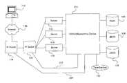
- a unified networking device in a data center environmentcommunicates directly with storage devices and servers in the data center and communicates directly with switches and routers outside of the data center environment.
- the unified networking devicemanages communications between storage devices, between a storage device and a server, between a storage device and a IP switch, and between a storage device and a router.
- the unified networking devicecomprises sixteen line cards having sixteen ports each so that the unified networking device includes two hundred fifty-six ports.
- the line cardscommunicate across a backplane with four switch cards to transfer packets from one port to another.
- Each line cardincludes four packet processors configured to process both incoming and outgoing packets for four ports.
- Each line cardalso includes four network processing units (NPUs) that perform upper layer processing on incoming and outgoing packets.
- NPUsnetwork processing units
- the unified networking deviceSince the unified networking device is able to communicate directly with network devices such as web switches and routers, the unified networking device can bypass servers and perform routine data transfers, such as large file transfer protocol (FTP) file transfers.
- the NPU of the unified networking deviceincludes a complete Transmission Control Protocol over Internet Protocol (TCP/IP) stack and applications for managing file transfers.
- TCP/IPTransmission Control Protocol over Internet Protocol
- use of the unified networking deviceunburdens the servers from mundane store-and-forward file transfers so that the servers' resources may be used for other applications.
- the unified networking devicehas a multi-protocol conversion functionality performed by the NPUs of the line cards. If a packet's protocol matches the protocol of its destination port, no conversion is needed. If the packet's protocol does not match the protocol of its destination port, but the two protocols have a common layer, an encapsulation protocol conversion method is used. If the packet's protocol does not match the protocol of its destination port and the two protocols have no common layer but the packet's protocol has a TCP-like functionality, the NPU acts as a TCP-proxy for the destination port.
- the NPUperforms a block storage conversion, reassembling the packets into an information unit and creating new packets according to the destination port's protocol.
- FIG. 1is a block diagram of a prior art embodiment of an electronic network system
- FIG. 2is a block diagram of one embodiment of an electronic network system including a unified networking device, according to the invention
- FIG. 3is block diagram of one embodiment of the unified networking device of FIG. 2 , according to the invention.
- FIG. 4is a diagram illustrating one embodiment of a data transfer, according to the invention.
- FIG. 5is a diagram illustrating another embodiment of a data transfer, according to the invention.
- FIG. 6is a flowchart of method steps for processing packets, according to one embodiment of the invention.
- FIG. 7Ais a functional block diagram of one embodiment of the block storage conversion functionality of unified networking device 210 , according to the invention.
- FIGS. 7B–7Dillustrate packets containing an information unit
- FIG. 8Ais a functional block diagram of one embodiment of the TCP-proxy functionality of unified networking device 210 , according to the invention.
- FIGS. 8B–8Dillustrate packets containing a message.
- FIG. 2is a block diagram of one embodiment of an electronic network system, according to the invention.
- An end user 110communicates via the Internet 112 with an Internet Protocol (IP) router 114 .
- IP router 114also communicates with an IP switch 116 , which in turn communicates with servers 118 .
- IPInternet Protocol
- FIG. 2a network system having any number of tiers with any number of servers is within the scope of the invention.
- IP router 114 and an IP switch 116are shown in FIG. 2 , any type of network router and any type of network switch are within the scope of the present invention.
- the network system of FIG. 2includes a unified networking device 210 that is configured to communicate with multiple types of devices.
- unified networking device 210communicates with servers 118 , RAID 126 , JBOD (Just a Bunch of Disks) 128 and 130 , and tape backup 132 .
- unified networking device 210communicates directly with IP router 114 via path 224 and with IP switch 116 via path 222 .
- storage devicessuch as RAID 126 may communicate via unified networking device 210 with IP switch 116 and IP router 114 .
- Unified networking device 210provides a single-hop communication path between a storage device and IP switch 116 and between a storage device and IP router 114 .
- a hoprefers to a device in a path between two devices in a network, where the number of hops in the path does not include the source device and the receiving device.
- RAID 126sends data to unified networking device 210 , which sends the data to server 118 , which sends the data to IP switch 116 .
- a path between RAID 126 and server 118includes one hop (unified networking device 210 ) and a path between RAID 126 and IP switch 116 includes two hops (unified networking device 210 and server 118 ).
- Another path between RAID 126 and IP switch 116includes one hop (unified networking device 210 ).
- unified networking device 210allows storage devices such as RAID 126 and JBOD 130 to exchange data without routing the data through a server or other conventional network appliance.
- unified networking device 210 , RAID 126 , JBODs 128 and 130 , servers 118 , and IP switch 116form a data center environment, where IP switch 116 is a load balancing network switch that balances network traffic among servers 118 .
- unified networking device 210manages communications between server 118 and IP switch 116 , and manages communications between server 118 and IP router 114 .
- unified networking device 210provides a single-hop communication path between any two devices that are connected to unified networking device 210 .
- Direct communication between unified networking device 210 and other devices in the networkallows unified networking device 210 to off-load some routine tasks, such as large FTP file transfers and remote tape backup, from server 118 , which frees up resources at server 118 for processing other applications. This server-bypassing is further discussed below in conjunction with FIGS. 4 & 5 .
- Unified networking device 210Communicating with various types of devices requires unified networking device 210 to implement communication protocols appropriate for each device supported, for example Gigabit Ethernet (GigE), Fibre Channel (FC), and InfiniBand (IB). Unified networking device 210 may also need to communicate using Small Computer System Interface (SCSI), Internet Protocol (IP), or other communication protocols. Unified networking device 210 is advantageously configured to perform multi-protocol conversion without assistance from a specialized protocol conversion device. The multi-protocol functionality allows unified networking device 210 to be used with legacy devices as well as newly-developed devices. Multi-protocol conversion as performed by unified networking device 210 is further described below in conjunction with FIGS. 6–8D .
- Unified networking device 210is typically a single unit, unlike the complex network of smaller devices implemented as SAN 124 .
- Unified networking device 210preferably provides two hundred and fifty six ports operable to communicate with various types of network devices; however, any number of ports is within the scope of the invention.
- Multiple unified networking device 210 rackscan be cascaded together to provide a unified networking device 210 with a larger number of ports.
- cascading multiple unified networking devices 210is disclosed in U.S.
- unified networking device 210is configured to manage communications among storage devices, such as RAID 126 and JBOD 130 , between storage devices and servers 118 , and between storage devices and IP switch 116 . In another embodiment, unified networking device 210 is further configured to manage communications between storage devices and IP router 114 . In other embodiments, unified networking device 210 is further configured to manage communications between server 118 and IP router 116 , and manage communications between server 118 and IP switch 114 .
- Unified networking device 210is simpler to implement than a typical storage area network such as SAN 124 of FIG. 1 .
- Unified networking device 210is typically implemented as a single device, instead of a multitude of interconnected devices, which reduces the amount of wires or cables in the physical environment.
- Unified networking device 210requires fewer physical connections to be maintained by support personnel. Additionally, if errors or faults occur in unified networking device 210 , a faulty component may be readily identified and replaced, in contrast to the time and effort required to physically identify and isolate a faulty device in a typical SAN.
- FIG. 3is block diagram of one embodiment of the unified networking device of FIG. 2 , according to the invention.
- Unified networking device 210includes, but is not limited to, four switch cards 202 , a passive backplane 214 , sixteen line cards including line card 212 , and two service processor cards (SPC 0 and SPC 1 ) 380 .
- Each line card 212includes sixteen ports 310 , each connected to a corresponding gigabit interface converter (GBIC) 320 , which in turn is connected to a corresponding physical layer component (PHY) 330 .
- GBICgigabit interface converter
- PHYphysical layer component
- Each PHY 330communicates with a packet processor (PP) 340 that performs layer two (switching) and layer three (routing) processing on incoming and outgoing packets.
- Each line card 212includes four packet processors (PP) 340 , where each packet processor 340 is an application specific integrated circuit (ASIC) configured to manage packets through four ports on line card 212 .
- Each packet processor 340is associated with a network processing unit (NPU) 342 , a dynamic random access memory (DRAM) 344 , and a static random access memory (SRAM) 346 .
- NPU 342in conjunction with DRAM 344 , performs higher layer (layers 3 – 7 ) processing on incoming and outgoing packets.
- SRAM 346buffers packets being processed by packet processor 340 .
- Each packet processor 340is able to simultaneously send four packets or cells across backplane 214 to any of the four switch cards 202 .
- Each switch card 202includes seventeen flow control ASICs (FLC) 204 , sixteen of which communicate with packet processors 340 and one of which communicates with service processor cards 380 .
- FLC 204is responsible for credit-based flow control queuing between line card 212 and a cross-bar switching fabric (XBAR) 206 .
- XBAR 206includes eight cross-bar ASICs.
- a scheduler 350receives requests from FLCs 204 and arbitrates access to XBAR 206 .
- a packet in the form of an optical signal or an electrical signalenters line card 212 at a port 310 .
- GBIC 320converts the optical or electrical signal into a high-speed serial differential electrical signal.
- PHY 330performs physical layer processing on the packet such as framing, clock recovery, and conversion to parallel signals, and then forwards the packet to packet processor 340 .
- Packet processor 340internally buffers the packet before performing lower layer (layer two and layer three) processing on the packet's header. Also, the packet's payload is stored in SRAM 346 until the packet is ready to be sent to switch card 202 .
- Lower layer processingincludes media access control, header parsing, destination port mapping, packet classification, and error handling. If packet processor 340 determines that the packet requires upper layer processing, then packet processor 340 sends the packet's header and a portion of its payload to NPU 342 .
- Upper layer processingincludes the handling of management and control packets and protocol conversion, if needed. Protocol conversion is further discussed below in conjunction with FIGS. 6–8D .
- Packet processor 340segments the packet into cells to reduce memory fragmentation of small packets. Each cell is preferably seventy-two bytes long, including a sixty-four byte payload and an eight byte header created by packet processor 340 .
- packet processor 340arbitrates for a connection through backplane 214 to switch card 202 . Once arbitration is complete, packet processor 340 sends the cells across backplane 214 to switch card 202 . Packet processor 340 preferably sends cells belonging to the same packet and packets belonging to the same flow (same source, destination, and priority) to the same switch card 202 to maintain cell and packet ordering.
- the cellsenter FLC 204 , which places each cell into a priority output queue (not shown).
- FLC 204sends switch requests to scheduler 350 for a cell at the head of the output queue.
- Scheduler 350receives requests from all FLCs 204 on switch card 202 , and determines which cells are switched to another FLC 204 during the next switching cycle.
- FLC 204sends the cell to XBAR 206 , which switches and sends the cell to a destination FLC 204 .
- the destination FLC 204arbitrates for a connection through backplane 214 to line card 212 .
- the destination FLC 204sends the cell across backplane 214 to a packet processor 340 that services the cell's destination port.
- Packet processor 340removes the cell's header and repackages the cell's payload into a packet.
- PHY 330processes the repackaged packet, and then GBIC 320 converts the packet to an optical signal or electrical signal and outputs the packet through its destination port 310 .
- Service processor 380transfers data between storage devices, for example between RAID 126 and JBOD 130 and between JBOD 128 and tape backup 132 ( FIG. 2 ), using the SCSI-3 protocol's third party copy feature. Data transfers between a storage device and end user 110 are discussed below in conjunction with FIGS. 4 & 5 .
- FIG. 4is a diagram illustrating one embodiment of a data transfer between end user 110 and JBOD 128 , according to the invention.
- FIG. 4shows network layers of the various devices active in the data transfer.
- An applicationsuch as a web browser at end user 110 requests a transfer of data from JBOD 128 using file transfer protocol (FTP).
- End user 110establishes a TCP peer-to-peer connection via IP router 114 and IP switch 116 to server 118 , according to a TCP three-way handshake.
- End user 110sends a SYN message to server 118 to synchronize sequence numbers.
- Server 118replies with an ACK message indicating the received sequence number of end user 110 and the sequence number of server 118 .
- End user 110replies with an ACK message indicating the received sequence number of server 118 .
- An application running at server 118receives the FTP request and prepares a request to JBOD 128 in the appropriate protocol, such as FC or IB.
- server 118sends the request directly to JBOD 128
- server 118sends the request via unified networking device 210 to JBOD 128 .
- Server 118then instructs unified networking device 210 to retrieve and then deliver the requested file to end user 110 .
- Unified networking device 210receives the data from JBOD 128 and converts the data into packets of the appropriate protocol, for example Ethernet over IP. The protocol conversion functionality of unified networking device 210 is discussed below in conjunction with FIGS. 6–8D .
- Unified networking device 210then sends the data to IP switch 116 , which sends the data to IP router 114 and finally to end user 110 .
- the TCP connection between end user 110 and server 118is then closed.
- server 118establishes and maintains a TCP connection with end user 110 .
- Unified networking device 210performs the actual task of transferring data from JBOD 128 to end user 110 .
- server 118is not completely bypassed during the file transfer; however, unified networking device 210 performs the time and resource consuming store-and-forward operations.
- FIG. 5is a diagram illustrating another embodiment of a data transfer from JBOD 128 and end user 110 , according to the invention.
- server 118does not establish a TCP connection with end user 110 and is not involved in the transfer of data from JBOD 128 to end user 110 .
- An applicationsuch as a web browser at end user 110 requests a transfer of data from JBOD 128 using file transfer protocol (FTP).
- FTPfile transfer protocol
- End user 110establishes a TCP peer-to-peer connection via IP router 114 and IP switch 116 with unified networking device 210 , according to a TCP three-way handshake.
- End user 110sends a SYN message to unified networking device 210 to synchronize sequence numbers.
- Unified networking device 210replies with an ACK message indicating the received sequence number of end user 110 and the sequence number of unified networking device 210 .
- End user 110replies with an ACK message indicating the received sequence number of unified networking device 210 .
- Unified networking device 210receives the FTP request and prepares a request for a file transfer in an appropriate protocol for JBOD 128 , for example FC or IB.
- the protocol conversion functionality of unified networking deviceis discussed below in conjunction with FIGS. 6–8D .
- JBOD 128begins transferring the file to unified networking device 210 , which then forwards the file to IP switch 116 for delivery to IP router 114 and end user 110 .
- NPU 342 ( FIG. 3 ) of unified networking device 210includes a complete TCP/IP protocol stack and functionalities that allow unified networking device 210 to perform simple server functions such as FTP file transfers.
- Unified networking device 210is a TCP proxy and communicates with server 118 to request certain functionalities like authentication and authorization. Unlike TCP proxies implemented in IP switches, unified networking device 210 does not save packets for retransmission. In case of a failure, for example a lost packet, unified networking device 210 will merely request retransmission from the data source such as JBOD 128 .
- end user 110establishes a TCP peer-to-peer connection via IP router 114 with unified networking device 210 , bypassing IP switch 116 .
- unified networking device 210receives an FTP request from end user 110 and prepares a request for a file transfer in an appropriate protocol for JBOD 128 , for example FC or IB.
- JBOD 128begins transferring the file to unified networking device 210 , which then forwards the file to IP router 114 for delivery to end user 110 .
- the server bypassing functionality of unified networking device 210allows the processing power of server 118 to be used for other applications while unified networking device 210 manages file transfers to end user 110 and data backups to tape backup 132 .
- server 118may be handling other customer transactions such as customer service chat sessions, providing application services, or processing other orders for software.
- the server bypassing functionality of unified networking device 210provides additional pathways for data transfers.
- unified networking device 210can manage communications between storage devices such as RAID 126 and JBOD 128 and communications between JBOD 130 and IP router 114 , while servers 118 manage additional communications with IP switch 116 . Thus more communications occur at the same time, allowing the owner of the data being transferred to serve additional numbers of customers or users.
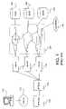
- FIG. 6is a flowchart of method steps for processing packets, according to one embodiment of the invention.
- multi-protocol processingoccurs after a packet is input to unified networking device 210 and is performed by NPU 342 in line card 212 .
- NPU 342receives an incoming packet and identifies its communication protocol.
- NPU 342identifies the destination port on unified networking device 210 and then looks up that port's protocol using a table stored in memory.
- NPU 342determines whether the packet's protocol matches the protocol of the destination port.
- step 628where PP 340 sends the packet to switch card 202 , which switches the packet to its destination port. If the protocols do not match, the method continues with step 618 where NPU 342 determines if the non-matching protocols have a common layer.
- NPU 342encapsulates the packet in the protocol of the destination port. NPU 342 strips down the packet to the common layer and then builds a new packet around the common layer to match the destination port protocol. The method then continues with step 628 , where PP 340 sends the new packet to switch card 202 , which switches the new packet to its destination port.
- NPU 342determines whether the packet's protocol has a TCP-like functionality. If the packet's protocol does not have a TCP-like functionality, then in step 624 line card 212 performs block storage conversion, which is described below in conjunction with FIGS. 7A–7D . If the packet's protocol has a TCP-like functionality, then in step 622 NPU 342 acts as a TCP-proxy for the destination device, which is described below in conjunction with FIGS. 8A–8D .
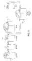
- FIG. 7Ais a functional block diagram of one embodiment of the block storage conversion functionality of unified networking device 210 , according to the invention.
- unified networking device 210communicates with two InfiniBand (IB) devices 714 and 716 , and three FibreChannel (FC) devices 718 , 720 , and 722 .
- IB and FC devicesare shown in FIG. 7A
- unified networking device 210may be configured to communicate with devices implementing any communication protocol.
- block storage conversionrefers to Small Computer System Interface (SCSI) protocol mapping over network protocols such as IB, FC, and IP.
- SCSISmall Computer System Interface
- Each supported network protocolhas an associated adaptation layer used in performing block storage.
- the IB adaptation layeris SCSI Remote Direct Memory Access protocol (SRP)
- the FC adaptation layeris FibreChannel Protocol for SCSI (FCP)
- IP adaptation layeris SCSI over IP (iSCSI).
- SCSI block storage datais quantized into information units.
- unified networking device 210includes, but is not limited to, an IB I/O controller 724 and an FC I/O controller 726 .
- Each I/O controlleris a line card 212 where each port 310 is configured to communicate using a specific protocol.
- all ports 310 of IB I/O controller 724use the IB protocol and all ports of FC I/O controller 726 use the FC protocol; however, in alternative embodiments an I/O controller may include ports 310 using different protocols (e.g., eight ports use IB and eight ports use FC).
- IB I/O controller 724 and FC I/O controller 726communicate via backplane 214 and switch cards 202 .
- each I/O controller(line card 212 ) strips each received packet down to its payload and reassembles the entire SCSI information unit.
- Packet processor 340performs layer two and layer three processing and NPU 342 performs higher layer processing.
- Each I/O controllerre-segments a received information unit into appropriate packets before sending them to the destination device.
- IB I/O controller 724 and FC I/O controller 726exchange information units across backplane 214 and switch card 202 .
- IB I/O controller 724maintains aliases 728 , 730 , and 732 for FC devices 718 , 720 , and 722 , respectively.
- IB I/O controller 724interacts with IB devices 714 and 716 as if FC devices 718 , 720 , and 722 were IB devices in communication with IB I/O controller 724 .
- IB devices 714 and 716“see” FC devices 718 , 720 , and 722 as if they were IB devices.
- IB I/O controller 724maps aliases 728 , 730 , and 732 as SRP logical units.
- FC I/O controller 726maintains aliases 734 and 736 for IB devices 714 and 716 , respectively.
- FC I/O controller 726interacts with FC devices 718 , 720 , and 722 as if IB devices 714 and 716 were FC devices in communication with FC I/O controller 726 .
- FC devices 718 , 720 , and 722“see” IB devices 714 and 716 as if they were FC devices.
- FC I/O controller 726maps aliases 734 and 736 as FCP logical units.
- IB device 714wants to send data to FC device 722 .
- IB device 714first sends an SRP request to IB I/O controller 724 addressed to the target device, FC device 722 .
- IB I/O controller 724receives the SRP request and identifies the destination device and the amount of data to be transferred.
- IB I/O controller 724generates a generic command descriptor and sends the descriptor to FC I/O controller 726 .
- IB device 714segments an information unit of the data into IB packets and sends the IB packets to IB I/O controller 724 , which accumulates the IB packets until the entire information unit has arrived.
- IB I/O controller 724then strips the IB packets of their header information and reassembles the information unit.
- IB I/O controller 724then segments the information unit into cells and sends the cells via backplane 214 and switch card 202 to FC I/O controller 726 .
- FC I/O controller 726receives the cells and reassembles the information unit. FC I/O controller 726 then segments the information unit into FC packets and sends the FC packets to FC device 722 . When FC device 722 has received all of the FC packets, FC device 722 sends an FCP response to FC I/O controller 726 to indicate the completed status of the data transfer. FC I/O controller 726 then sends the generic command descriptor back to IB I/O controller 724 , which generates an SRP response and sends the SRP response to IB device 714 to indicate that the data transfer is complete.
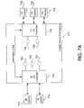
- FIG. 7Billustrates three InfiniBand packets containing segments of an information unit.
- IB device 714segments an information unit into three parts, information A, information B, and information C. Although three packets are shown in FIG. 7B , an information unit may be packaged in any number of packets.
- IB device 714then creates a packet for each information segment.
- information Ais preceded by a SCSI header, an SRP header, and an IB header.
- information Bis preceded by a SCSI header, an SRP header, and an IB header.
- information Cis preceded by a SCSI header, an SRP header, and an IB header.
- IB device 714sends packets 742 , 744 , and 746 to IB I/O controller 724 of unified networking device 210 .
- IB I/O controller 724strips packets 742 , 744 , and 746 to their payloads of information A, information B, and information C.
- Packet processor 340 of IB I/O controller 724strips the IB and SRP headers from packets 742 , 744 , and 746 , then NPU 342 strips the SCSI header from packets 742 , 744 , and 746 .
- NPU 342 of IB I/O controller 724then concatenates the payloads to rebuild the information unit 748 , as shown in FIG. 7C .
- IB I/O controller 724then sends the information unit to FC I/O controller 726 .
- NPU 342 of FC I/O controller 726segments the information unit 750 into four segments, as shown in FIG. 7C . Although four segments are shown in FIG. 7C , FC I/O controller 726 may segment the information unit into any number of segments.
- FC I/O controller 726then builds a packet for each segment of the information unit 750 .
- a first packet 752includes information 1 preceded by a SCSI header, an FCP header, and an FC header.
- a second packet 754includes information 2 preceded by a SCSI header, an FCP header, and an FC header.
- a third packet 756includes information 3 preceded by a SCSI header, an FCP header, and an FC header.
- a fourth packet 758includes information 4 preceded by a SCSI header, an FCP header, and an FC header.
- FC I/O controller 726then sends packets 752 , 754 , 756 , and 758 to FC device 722 .
- NPU 342 of FC I/O controller 726adds the SCSI header to packets 752 , 754 , 756 , and 758 , then packet processor 340 adds the FCP and FC headers to packets 752 , 754 , 756 , and 758 .
- FIG. 8Ais a functional block diagram of one embodiment of the TCP-proxy functionality of unified networking device 210 , according to the invention.
- the TCP-proxy functionality of unified networking device 210operates when the protocols of the sending device and the destination device do not have a common layer, such as IP, and the sending device formats outgoing data as TCP messages.
- unified networking device 210includes, but is not limited to, an Ethernet I/O controller 824 and FC I/O controller 726 , which communicate via backplane 214 and switch card 202 (not shown).
- Each I/O controlleris a line card 212 where each port 310 is configured to communicate using a specific protocol.
- all ports 310 of Ethernet I/O controller 824use the Ethernet protocol and all ports of FC I/O controller 726 use the FC protocol; however, in alternative embodiments an I/O controller may include ports 310 using different protocols (e.g., eight ports use Ethernet and eight ports use FC).
- Ethernet I/O controller 824communicates with two Ethernet devices 814 and 816 using Ethernet over TCP/IP packets.
- Ethernet I/O controller 824maintains aliases 828 , 830 , and 832 representing FC devices 718 , 720 , and 722 , respectively.
- FC I/O controller 726maintains aliases 834 and 836 representing Ethernet devices 814 and 816 , respectively.
- Ethernet device 814wants to send data to FC device 722 .
- Ethernet device 814establishes a TCP connection with alias 832 of Ethernet I/O controller 824 .
- Ethernet device 814then sends Ethernet packets representing a TCP message to Ethernet I/O controller 824 .
- Ethernet I/O controller 824accumulates the Ethernet packets, discarding the Ethernet, IP, and TCP header information, until the entire TCP message is received.
- Packet processor 340 of Ethernet I/O controller 824removes the Ethernet and IP headers and NPU 342 removes the TCP headers.
- Ethernet I/O controller 824then segments the message portion of TCP (containing the information unit between initiator and target) into cells and sends the cells via backplane 214 and switch card 202 to FC I/O controller 726 .
- FC I/O controller 726accumulates the cells until the entire message arrives.
- FC I/O controller 726then segments the message into FC packets and sends the FC packets to FC device 722 .
- Ethernet I/O controller 824acts as a TCP-proxy for FC devices 718 , 720 , and 722 .
- Ethernet I/O controller 824sends acknowledgments for each packet to Ethernet device 814 , which interprets the acknowledgments as coming from alias 832 that represents FC device 722 .
- An NPU 342 on Ethernet I/O controller 824implements a complete TCP/IP protocol stack.
- Ethernet device 816wants to receive data from FC device 720 .
- Ethernet device 816sends packets to Ethernet I/O controller 824 , performing a TCP “handshake” with alias 830 .
- Ethernet I/O controller 824generates a generic command descriptor that identifies the requested data and sends the descriptor to FC I/O controller 726 .
- FC I/O controller 726requests the data from FC device 720 , which sees the request as originating from alias 836 .
- FC device 720sends FC packets containing the requested data to FC I/O controller 726 , which accumulates the packets until the entire requested data is received.
- FC I/O controller 726then segments the data into cells and sends the cells to Ethernet I/O controller 824 , where the cells are accumulated to form a TCP message.
- Ethernet I/O controller 824then segments the TCP message into Ethernet over TCP/IP packets and sends the packets to Ethernet device 816 .
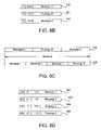
- FIG. 8Billustrates three FibreChannel packets containing segments of a message.
- FC device 720segments the message into three parts, message A, message B, and message C. Although three packets are shown in FIG. 8B , a message may be packaged in any number of packets.
- a first packet 842includes message A preceded by an FCP header and an FC header.
- a second packet 844includes message B preceded by an FCP header and an FC header.
- a third packet 846includes message C preceded by an FCP header and an FC header.
- FC device 720sends packets 842 , 844 , and 846 to FC I/O controller 726 of unified networking device 210 .
- FC I/O controller 726strips packets 842 , 844 , and 846 to their payloads of message A, message B, and message C.
- Packet processor 340 of FC I/O controller 726removes the FC header from packets 842 , 844 , and 846
- NPU 342removes the FCP header from packets 842 , 844 , and 846 .
- NPU 342 of FC I/O controller 726then concatenates message A, message B, and message C to form a complete message 848 as shown in FIG. 8C .
- FC I/O controller 726sends the complete message to Ethernet I/O controller 824 .
- Ethernet I/O controller 824receives the complete message and segments the message 850 into four parts, as shown in FIG. 8C . Although message 850 has four parts, a message may be segmented into any number of parts. Ethernet I/O controller 824 then creates an Ethernet packet for each message part.
- a first Ethernet packet 852includes message 1 preceded by a TCP header, an IP header, and an Ethernet header.
- a second Ethernet packet 854includes message 2 preceded by a TCP header, an IP header, and an Ethernet header.
- a third packet 856includes message 3 preceded by a TCP header, an IP header, and an Ethernet header.
- a fourth packet 858includes message 4 preceded by a TCP header, an IP header, and an Ethernet header.
- Ethernet I/O controller 824then sends packets 852 , 854 , 856 , and 858 to Ethernet device 816 .
- NPU 342 of Ethernet I/O controller 824adds the TCP header to packets 852 , 854 , 856 , and 858
- packet processor 340add the IP and Ethernet headers to packets 852 , 854 , 856 , and 858 .
- the multi-protocol conversion functionality of unified networking device 210provides flexibility in the implementation of a data center. For example, legacy storage devices containing valuable customer data may communicate with newly developed servers or other devices which use a new or different protocol. A user of unified networking device 210 can swap a line card 212 with a new line card 212 configured to implement the protocol of the new device. In an alternate embodiment, an existing line card 212 can be reprogrammed to implement the new protocol, thus requiring no new equipment. A user of unified networking device 210 also has more flexibility in selecting devices to use in the data center. Since unified networking device 210 has the multi-protocol conversion functionality, the user may select the best performing devices for use in the data center without being limited to devices that use one particular protocol. For example, the user may mix and match InfiniBand devices, FibreChannel devices, Ethernet devices, Universal Serial Bus (USB) devices, or any other type of networking devices.
- USBUniversal Serial Bus
- Unified networking device 210provides a direct, single-hop path between storage devices, between a storage device and a server, between a storage device and a network switch, and between a storage device and a router. Unified networking device 210 also provides a direct, single-hop path between a server and a router, and between a server and a network switch. Unified networking device 210 can be configured to communicate with any type of networking device. By providing these direct pathways between devices, unified networking device 210 allows communications such as data transfers to bypass a server, freeing up server resources that can be allocated to other tasks. Unified networking device 210 also includes a multi-protocol conversion functionality such that the various devices that communicate via unified networking device 210 are not required to use the same communication protocol.
Landscapes
- Engineering & Computer Science (AREA)
- Computer Networks & Wireless Communication (AREA)
- Signal Processing (AREA)
- Computer Security & Cryptography (AREA)
- Data Exchanges In Wide-Area Networks (AREA)
Abstract
Description
Claims (66)
Priority Applications (1)
| Application Number | Priority Date | Filing Date | Title |
|---|---|---|---|
| US09/944,425US7194550B1 (en) | 2001-08-30 | 2001-08-30 | Providing a single hop communication path between a storage device and a network switch |
Applications Claiming Priority (1)
| Application Number | Priority Date | Filing Date | Title |
|---|---|---|---|
| US09/944,425US7194550B1 (en) | 2001-08-30 | 2001-08-30 | Providing a single hop communication path between a storage device and a network switch |
Publications (1)
| Publication Number | Publication Date |
|---|---|
| US7194550B1true US7194550B1 (en) | 2007-03-20 |
Family
ID=37863954
Family Applications (1)
| Application Number | Title | Priority Date | Filing Date |
|---|---|---|---|
| US09/944,425Expired - Fee RelatedUS7194550B1 (en) | 2001-08-30 | 2001-08-30 | Providing a single hop communication path between a storage device and a network switch |
Country Status (1)
| Country | Link |
|---|---|
| US (1) | US7194550B1 (en) |
Cited By (35)
| Publication number | Priority date | Publication date | Assignee | Title |
|---|---|---|---|---|
| KR100385100B1 (en)* | 1993-05-04 | 2003-08-14 | 헌터 더글라스 인터내셔널 엔. 브이. | Cell phone |
| US20040177130A1 (en)* | 2003-03-07 | 2004-09-09 | International Business Machines Corporation | Use of virtual targets for preparing and servicing requests for server-free data transfer operations |
| US20050243870A1 (en)* | 2004-04-14 | 2005-11-03 | Balogh Dan A | Method of transferring call transition messages between network controllers of different radio technologies |
| US20060069789A1 (en)* | 2004-09-27 | 2006-03-30 | Kridner Jason D | Apparatus and method for improved transfer of files using an internet protocol |
| US20070185973A1 (en)* | 2006-02-07 | 2007-08-09 | Dot Hill Systems, Corp. | Pull data replication model |
| US20080005307A1 (en)* | 2006-06-29 | 2008-01-03 | Witness Systems, Inc. | Systems and methods for providing recording as a network service |
| US20080072003A1 (en)* | 2006-03-28 | 2008-03-20 | Dot Hill Systems Corp. | Method and apparatus for master volume access during colume copy |
| US20080159260A1 (en)* | 2006-12-15 | 2008-07-03 | Brocade Communications Systems, Inc. | Fibre channel over ethernet frame |
| US20080159277A1 (en)* | 2006-12-15 | 2008-07-03 | Brocade Communications Systems, Inc. | Ethernet over fibre channel |
| US20080177954A1 (en)* | 2007-01-18 | 2008-07-24 | Dot Hill Systems Corp. | Method and apparatus for quickly accessing backing store metadata |
| US20080177957A1 (en)* | 2007-01-18 | 2008-07-24 | Dot Hill Systems Corp. | Deletion of rollback snapshot partition |
| US20080181243A1 (en)* | 2006-12-15 | 2008-07-31 | Brocade Communications Systems, Inc. | Ethernet forwarding in high performance fabrics |
| US20080256311A1 (en)* | 2007-04-11 | 2008-10-16 | Dot Hill Systems Corp. | Snapshot preserved data cloning |
| US20080256141A1 (en)* | 2007-04-11 | 2008-10-16 | Dot Hill Systems Corp. | Method and apparatus for separating snapshot preserved and write data |
| US20080281877A1 (en)* | 2007-05-10 | 2008-11-13 | Dot Hill Systems Corp. | Backing store re-initialization method and apparatus |
| US20080281875A1 (en)* | 2007-05-10 | 2008-11-13 | Dot Hill Systems Corp. | Automatic triggering of backing store re-initialization |
| US20080320258A1 (en)* | 2007-06-25 | 2008-12-25 | Dot Hill Systems Corp. | Snapshot reset method and apparatus |
| EP2061181A1 (en)* | 2007-11-15 | 2009-05-20 | Hewlett-Packard Development Company, L.P. | Communication methods and systems |
| US20090132701A1 (en)* | 2007-11-20 | 2009-05-21 | Robert Snively | Duplicate address discovery and action |
| US20090292813A1 (en)* | 2007-12-17 | 2009-11-26 | Brocade Communications Systems, Inc. | Address Assignment in Fibre Channel Over Ethernet Environments |
| US20090296726A1 (en)* | 2008-06-03 | 2009-12-03 | Brocade Communications Systems, Inc. | ACCESS CONTROL LIST MANAGEMENT IN AN FCoE ENVIRONMENT |
| US20100183011A1 (en)* | 2007-06-11 | 2010-07-22 | Blade Network Technologies, Inc. | Sequential frame forwarding |
| US20100265824A1 (en)* | 2007-11-09 | 2010-10-21 | Blade Network Technologies, Inc | Session-less Load Balancing of Client Traffic Across Servers in a Server Group |
| US20110026527A1 (en)* | 2007-06-11 | 2011-02-03 | Blade Network Technologies, Inc. | Tag-based interface between a switching device and servers for use in frame processing and forwarding |
| US20110026403A1 (en)* | 2007-11-09 | 2011-02-03 | Blade Network Technologies, Inc | Traffic management of client traffic at ingress location of a data center |
| US8595352B2 (en) | 2006-03-22 | 2013-11-26 | Brocade Communications Systems, Inc. | Protocols for connecting intelligent service modules in a storage area network |
| US8848575B2 (en) | 2009-02-23 | 2014-09-30 | Brocade Communications Systems, Inc. | High availability and multipathing for fibre channel over ethernet |
| US20150092771A1 (en)* | 2013-10-02 | 2015-04-02 | Evertz Microsystems Ltd. | Video router |
| US9426067B2 (en) | 2012-06-12 | 2016-08-23 | International Business Machines Corporation | Integrated switch for dynamic orchestration of traffic |
| US20180198709A1 (en)* | 2004-11-16 | 2018-07-12 | Intel Corporation | Packet coalescing |
| CN110495149A (en)* | 2017-05-26 | 2019-11-22 | 西门子股份公司 | Data transmission method and device |
| CN110781152A (en)* | 2019-10-09 | 2020-02-11 | 济南浪潮数据技术有限公司 | Multi-protocol data sharing architecture |
| US20200076925A1 (en)* | 2018-08-29 | 2020-03-05 | Tianjin Chip Sea Innovation Technology Co. Ltd. | Software-defined Interconnection Method and Apparatus for Heterogeneous Protocol Data |
| US11343317B2 (en) | 2017-05-25 | 2022-05-24 | Siemens Aktiengesellschaft | Data transmission method and device |
| US12207013B2 (en) | 2020-08-31 | 2025-01-21 | Evertz Microsystems Ltd. | Systems and methods for down-sampled video routing |
Citations (8)
| Publication number | Priority date | Publication date | Assignee | Title |
|---|---|---|---|---|
| US5751710A (en)* | 1996-06-11 | 1998-05-12 | Cisco Technology, Inc. | Technique for connecting cards of a distributed network switch |
| US5828905A (en)* | 1995-11-13 | 1998-10-27 | Mitsubishi Chemical America, Inc. | Adapter and method of connecting devices associated with at least three different protocols |
| US6000020A (en)* | 1997-04-01 | 1999-12-07 | Gadzoox Networks, Inc. | Hierarchical storage management from a mirrored file system on a storage network segmented by a bridge |
| US6400730B1 (en)* | 1999-03-10 | 2002-06-04 | Nishan Systems, Inc. | Method and apparatus for transferring data between IP network devices and SCSI and fibre channel devices over an IP network |
| US6535518B1 (en)* | 2000-02-10 | 2003-03-18 | Simpletech Inc. | System for bypassing a server to achieve higher throughput between data network and data storage system |
| US6601101B1 (en)* | 2000-03-15 | 2003-07-29 | 3Com Corporation | Transparent access to network attached devices |
| US6724757B1 (en)* | 1999-01-15 | 2004-04-20 | Cisco Technology, Inc. | Configurable network router |
| US6894979B1 (en)* | 2001-04-24 | 2005-05-17 | Crossroads Systems, Inc. | Network analyzer/sniffer with multiple protocol capabilities |
- 2001
- 2001-08-30USUS09/944,425patent/US7194550B1/ennot_activeExpired - Fee Related
Patent Citations (8)
| Publication number | Priority date | Publication date | Assignee | Title |
|---|---|---|---|---|
| US5828905A (en)* | 1995-11-13 | 1998-10-27 | Mitsubishi Chemical America, Inc. | Adapter and method of connecting devices associated with at least three different protocols |
| US5751710A (en)* | 1996-06-11 | 1998-05-12 | Cisco Technology, Inc. | Technique for connecting cards of a distributed network switch |
| US6000020A (en)* | 1997-04-01 | 1999-12-07 | Gadzoox Networks, Inc. | Hierarchical storage management from a mirrored file system on a storage network segmented by a bridge |
| US6724757B1 (en)* | 1999-01-15 | 2004-04-20 | Cisco Technology, Inc. | Configurable network router |
| US6400730B1 (en)* | 1999-03-10 | 2002-06-04 | Nishan Systems, Inc. | Method and apparatus for transferring data between IP network devices and SCSI and fibre channel devices over an IP network |
| US6535518B1 (en)* | 2000-02-10 | 2003-03-18 | Simpletech Inc. | System for bypassing a server to achieve higher throughput between data network and data storage system |
| US6601101B1 (en)* | 2000-03-15 | 2003-07-29 | 3Com Corporation | Transparent access to network attached devices |
| US6894979B1 (en)* | 2001-04-24 | 2005-05-17 | Crossroads Systems, Inc. | Network analyzer/sniffer with multiple protocol capabilities |
Non-Patent Citations (8)
| Title |
|---|
| Clark, Tom, "iSNS: Technical overview of discovery in IP SANs," InfoStor, <http://is.pennet.com/Articles/Articles<SUB>-</SUB>Display.cfm?Section=Articles&Subsection=Display&Article<SUB>-</SUB>ID=126602&KEYWORD=iscsi>, Nov. 2001. |
| Dot Hill Systems Corp., "SAN Tutorial," (visited Apr. 3, 2001), <http://www.the-storage-in.com/topic01.htm>. |
| Ottem, Erik, "SANs for High Availability Systems," Gadzoox Networks whitepaper 2001. |
| Tanner, Dan, "IP-based storage: The buzz on the wire," InfoStor, <http://is.pennet.com/Articles/Article<SUB>-</SUB>Display.cfm?Section=Articles&Subsection=Display&Article<SUB>-</SUB>ID=104660&KEYWORD=iscsi>, Jun. 2001. |
| U.S. Appl. No. 09/892,216, Chamdani et al., filed Jun. 25, 2001. |
| U.S. Appl. No. 09/895,288, Chamdani et al., filed Jun. 29, 2001. |
| U.S. Appl. No. 09/943,660, Chamdani et al., filed Aug. 30, 2001. |
| U.S. Appl. No. 09/943,842, Chamdani et al., filed Aug. 30, 2001. |
Cited By (77)
| Publication number | Priority date | Publication date | Assignee | Title |
|---|---|---|---|---|
| KR100385100B1 (en)* | 1993-05-04 | 2003-08-14 | 헌터 더글라스 인터내셔널 엔. 브이. | Cell phone |
| US7660866B2 (en) | 2003-03-07 | 2010-02-09 | International Business Machines Corporation | Use of virtual targets for preparing and servicing requests for server-free data transfer operations |
| US20040177130A1 (en)* | 2003-03-07 | 2004-09-09 | International Business Machines Corporation | Use of virtual targets for preparing and servicing requests for server-free data transfer operations |
| US20080288670A1 (en)* | 2003-03-07 | 2008-11-20 | International Business Machines Corporation | Use of virtual targets for preparing and servicing requests for server-free data transfer operations |
| US7461131B2 (en)* | 2003-03-07 | 2008-12-02 | International Business Machines Corporation | Use of virtual targets for preparing and servicing requests for server-free data transfer operations |
| US20050243870A1 (en)* | 2004-04-14 | 2005-11-03 | Balogh Dan A | Method of transferring call transition messages between network controllers of different radio technologies |
| US7978683B2 (en)* | 2004-04-14 | 2011-07-12 | Alcatel-Lucent Usa Inc. | Method of transferring call transition messages between network controllers of different radio technologies |
| US20060069789A1 (en)* | 2004-09-27 | 2006-03-30 | Kridner Jason D | Apparatus and method for improved transfer of files using an internet protocol |
| US10652147B2 (en)* | 2004-11-16 | 2020-05-12 | Intel Corporation | Packet coalescing |
| US20180198709A1 (en)* | 2004-11-16 | 2018-07-12 | Intel Corporation | Packet coalescing |
| US20070185973A1 (en)* | 2006-02-07 | 2007-08-09 | Dot Hill Systems, Corp. | Pull data replication model |
| US8990153B2 (en) | 2006-02-07 | 2015-03-24 | Dot Hill Systems Corporation | Pull data replication model |
| US20110072104A2 (en)* | 2006-02-07 | 2011-03-24 | Dot Hill Systems Corporation | Pull data replication model |
| US20110087792A2 (en)* | 2006-02-07 | 2011-04-14 | Dot Hill Systems Corporation | Data replication method and apparatus |
| US20070186001A1 (en)* | 2006-02-07 | 2007-08-09 | Dot Hill Systems Corp. | Data replication method and apparatus |
| US8595352B2 (en) | 2006-03-22 | 2013-11-26 | Brocade Communications Systems, Inc. | Protocols for connecting intelligent service modules in a storage area network |
| US7783850B2 (en) | 2006-03-28 | 2010-08-24 | Dot Hill Systems Corporation | Method and apparatus for master volume access during volume copy |
| US20080072003A1 (en)* | 2006-03-28 | 2008-03-20 | Dot Hill Systems Corp. | Method and apparatus for master volume access during colume copy |
| US7660307B2 (en)* | 2006-06-29 | 2010-02-09 | Verint Americas Inc. | Systems and methods for providing recording as a network service |
| US20080005307A1 (en)* | 2006-06-29 | 2008-01-03 | Witness Systems, Inc. | Systems and methods for providing recording as a network service |
| US20080159260A1 (en)* | 2006-12-15 | 2008-07-03 | Brocade Communications Systems, Inc. | Fibre channel over ethernet frame |
| US20080181243A1 (en)* | 2006-12-15 | 2008-07-31 | Brocade Communications Systems, Inc. | Ethernet forwarding in high performance fabrics |
| US20080159277A1 (en)* | 2006-12-15 | 2008-07-03 | Brocade Communications Systems, Inc. | Ethernet over fibre channel |
| US20080177957A1 (en)* | 2007-01-18 | 2008-07-24 | Dot Hill Systems Corp. | Deletion of rollback snapshot partition |
| US8751467B2 (en) | 2007-01-18 | 2014-06-10 | Dot Hill Systems Corporation | Method and apparatus for quickly accessing backing store metadata |
| US7831565B2 (en) | 2007-01-18 | 2010-11-09 | Dot Hill Systems Corporation | Deletion of rollback snapshot partition |
| US20080177954A1 (en)* | 2007-01-18 | 2008-07-24 | Dot Hill Systems Corp. | Method and apparatus for quickly accessing backing store metadata |
| US8656123B2 (en) | 2007-04-11 | 2014-02-18 | Dot Hill Systems Corporation | Snapshot preserved data cloning |
| US20090307450A1 (en)* | 2007-04-11 | 2009-12-10 | Dot Hill Systems Corporation | Snapshot Preserved Data Cloning |
| US7975115B2 (en) | 2007-04-11 | 2011-07-05 | Dot Hill Systems Corporation | Method and apparatus for separating snapshot preserved and write data |
| US20080256141A1 (en)* | 2007-04-11 | 2008-10-16 | Dot Hill Systems Corp. | Method and apparatus for separating snapshot preserved and write data |
| US7716183B2 (en) | 2007-04-11 | 2010-05-11 | Dot Hill Systems Corporation | Snapshot preserved data cloning |
| US20080256311A1 (en)* | 2007-04-11 | 2008-10-16 | Dot Hill Systems Corp. | Snapshot preserved data cloning |
| US7783603B2 (en) | 2007-05-10 | 2010-08-24 | Dot Hill Systems Corporation | Backing store re-initialization method and apparatus |
| US20080281875A1 (en)* | 2007-05-10 | 2008-11-13 | Dot Hill Systems Corp. | Automatic triggering of backing store re-initialization |
| US20080281877A1 (en)* | 2007-05-10 | 2008-11-13 | Dot Hill Systems Corp. | Backing store re-initialization method and apparatus |
| US8001345B2 (en) | 2007-05-10 | 2011-08-16 | Dot Hill Systems Corporation | Automatic triggering of backing store re-initialization |
| US20110026527A1 (en)* | 2007-06-11 | 2011-02-03 | Blade Network Technologies, Inc. | Tag-based interface between a switching device and servers for use in frame processing and forwarding |
| US9667442B2 (en) | 2007-06-11 | 2017-05-30 | International Business Machines Corporation | Tag-based interface between a switching device and servers for use in frame processing and forwarding |
| US8559429B2 (en) | 2007-06-11 | 2013-10-15 | International Business Machines Corporation | Sequential frame forwarding |
| US20100183011A1 (en)* | 2007-06-11 | 2010-07-22 | Blade Network Technologies, Inc. | Sequential frame forwarding |
| US20080320258A1 (en)* | 2007-06-25 | 2008-12-25 | Dot Hill Systems Corp. | Snapshot reset method and apparatus |
| US8200631B2 (en) | 2007-06-25 | 2012-06-12 | Dot Hill Systems Corporation | Snapshot reset method and apparatus |
| US8204858B2 (en) | 2007-06-25 | 2012-06-19 | Dot Hill Systems Corporation | Snapshot reset method and apparatus |
| US20110026403A1 (en)* | 2007-11-09 | 2011-02-03 | Blade Network Technologies, Inc | Traffic management of client traffic at ingress location of a data center |
| US8553537B2 (en) | 2007-11-09 | 2013-10-08 | International Business Machines Corporation | Session-less load balancing of client traffic across servers in a server group |
| US20100265824A1 (en)* | 2007-11-09 | 2010-10-21 | Blade Network Technologies, Inc | Session-less Load Balancing of Client Traffic Across Servers in a Server Group |
| US8867341B2 (en) | 2007-11-09 | 2014-10-21 | International Business Machines Corporation | Traffic management of client traffic at ingress location of a data center |
| US20090132397A1 (en)* | 2007-11-15 | 2009-05-21 | Hewlett-Packard Development Company, L.P. | Communication methods and systems |
| US8219449B2 (en) | 2007-11-15 | 2012-07-10 | Hewlett-Packard Development Company, L.P. | Communication methods and systems |
| EP2061181A1 (en)* | 2007-11-15 | 2009-05-20 | Hewlett-Packard Development Company, L.P. | Communication methods and systems |
| US8583780B2 (en) | 2007-11-20 | 2013-11-12 | Brocade Communications Systems, Inc. | Discovery of duplicate address in a network by reviewing discovery frames received at a port |
| US20090132701A1 (en)* | 2007-11-20 | 2009-05-21 | Robert Snively | Duplicate address discovery and action |
| US8108454B2 (en) | 2007-12-17 | 2012-01-31 | Brocade Communications Systems, Inc. | Address assignment in Fibre Channel over Ethernet environments |
| US20090292813A1 (en)* | 2007-12-17 | 2009-11-26 | Brocade Communications Systems, Inc. | Address Assignment in Fibre Channel Over Ethernet Environments |
| US20090296726A1 (en)* | 2008-06-03 | 2009-12-03 | Brocade Communications Systems, Inc. | ACCESS CONTROL LIST MANAGEMENT IN AN FCoE ENVIRONMENT |
| US8848575B2 (en) | 2009-02-23 | 2014-09-30 | Brocade Communications Systems, Inc. | High availability and multipathing for fibre channel over ethernet |
| US9906446B2 (en) | 2012-06-12 | 2018-02-27 | International Business Machines Corporation | Integrated switch for dynamic orchestration of traffic |
| US9660910B2 (en) | 2012-06-12 | 2017-05-23 | International Business Machines Corporation | Integrated switch for dynamic orchestration of traffic |
| US9426067B2 (en) | 2012-06-12 | 2016-08-23 | International Business Machines Corporation | Integrated switch for dynamic orchestration of traffic |
| US20150092771A1 (en)* | 2013-10-02 | 2015-04-02 | Evertz Microsystems Ltd. | Video router |
| US9942139B2 (en)* | 2013-10-02 | 2018-04-10 | Evertz Microsystems Ltd. | Video router |
| US9654391B2 (en)* | 2013-10-02 | 2017-05-16 | Evertz Microsystems Ltd. | Video router |
| US10164877B2 (en)* | 2013-10-02 | 2018-12-25 | Evertz Microsystems Ltd. | Video router |
| US20190081893A1 (en)* | 2013-10-02 | 2019-03-14 | Evertz Microsystems Ltd. | Video router |
| US12149443B2 (en) | 2013-10-02 | 2024-11-19 | Evertz Microsystems Ltd. | Video router |
| US11418442B2 (en) | 2013-10-02 | 2022-08-16 | Evertz Microsystems Ltd. | Video router |
| US10587506B2 (en)* | 2013-10-02 | 2020-03-10 | Evertz Microsystems Ltd. | Video router |
| US20170279711A1 (en)* | 2013-10-02 | 2017-09-28 | Evertz Microsystems Ltd. | Video router |
| US11343317B2 (en) | 2017-05-25 | 2022-05-24 | Siemens Aktiengesellschaft | Data transmission method and device |
| CN110495149B (en)* | 2017-05-26 | 2022-04-08 | 西门子股份公司 | Data transmission method and device |
| EP3618378A4 (en)* | 2017-05-26 | 2020-09-09 | Siemens Aktiengesellschaft | DATA TRANSFER METHOD AND DEVICE |
| CN110495149A (en)* | 2017-05-26 | 2019-11-22 | 西门子股份公司 | Data transmission method and device |
| US20200076925A1 (en)* | 2018-08-29 | 2020-03-05 | Tianjin Chip Sea Innovation Technology Co. Ltd. | Software-defined Interconnection Method and Apparatus for Heterogeneous Protocol Data |
| CN110781152B (en)* | 2019-10-09 | 2022-04-22 | 济南浪潮数据技术有限公司 | Multi-protocol data sharing architecture |
| CN110781152A (en)* | 2019-10-09 | 2020-02-11 | 济南浪潮数据技术有限公司 | Multi-protocol data sharing architecture |
| US12207013B2 (en) | 2020-08-31 | 2025-01-21 | Evertz Microsystems Ltd. | Systems and methods for down-sampled video routing |
Similar Documents
| Publication | Publication Date | Title |
|---|---|---|
| US7194550B1 (en) | Providing a single hop communication path between a storage device and a network switch | |
| US6687758B2 (en) | Port aggregation for network connections that are offloaded to network interface devices | |
| US7110394B1 (en) | Packet switching apparatus including cascade ports and method for switching packets | |
| US7346702B2 (en) | System and method for highly scalable high-speed content-based filtering and load balancing in interconnected fabrics | |
| EP1690359B1 (en) | Apparatus and method for performing fast fibre channel write operations over relatively high latency networks | |
| US6400730B1 (en) | Method and apparatus for transferring data between IP network devices and SCSI and fibre channel devices over an IP network | |
| EP0889624B1 (en) | Trunking ethernet-compatible networks | |
| US7145866B1 (en) | Virtual network devices | |
| US8438321B2 (en) | Method and system for supporting hardware acceleration for iSCSI read and write operations and iSCSI chimney | |
| US20160191571A1 (en) | Applications processing in a network apparatus | |
| US6795866B1 (en) | Method and apparatus for forwarding packet fragments | |
| US6233245B1 (en) | Method and apparatus for management of bandwidth in a data communication network | |
| US20030103455A1 (en) | Mechanism for implementing class redirection in a cluster | |
| WO2001059966A1 (en) | Method and apparatus for transferring data between different network devices over an ip network | |
| Telikepalli et al. | Storage area network extension solutions and their performance assessment | |
| CN102656850A (en) | Method for processing a plurality of data and switching device for switching communication packets | |
| US6925078B1 (en) | Network adaptor driver with destination based ordering | |
| JP2012521103A (en) | Method and system for providing a logical network layer for transmitting input / output data | |
| US20050192967A1 (en) | Apparatus and method for performing fast fibre channel write operations over relatively high latency networks | |
| US7580410B2 (en) | Extensible protocol processing system | |
| US8527661B1 (en) | Gateway for connecting clients and servers utilizing remote direct memory access controls to separate data path from control path | |
| EP1759317B1 (en) | Method and system for supporting read operations for iscsi and iscsi chimney | |
| EP1540473B1 (en) | System and method for network interfacing in a multiple network environment | |
| US7706316B1 (en) | Processing an incoming packet of unknown protocol by encapsulating the packet and sending it to another processor | |
| JP3792538B2 (en) | System and method for peer level communication using a network interface card |
Legal Events
| Date | Code | Title | Description |
|---|---|---|---|
| AS | Assignment | Owner name:SANERA SYSTEMS INC., CALIFORNIA Free format text:ASSIGNMENT OF ASSIGNORS INTEREST;ASSIGNORS:CHAMDANI, JOSEPH I.;CHERABUDDI, RAJ;MUDDU, SUDHAKAR;REEL/FRAME:012417/0977 Effective date:20010912 | |
| FEPP | Fee payment procedure | Free format text:PAYOR NUMBER ASSIGNED (ORIGINAL EVENT CODE: ASPN); ENTITY STATUS OF PATENT OWNER: LARGE ENTITY | |
| STCF | Information on status: patent grant | Free format text:PATENTED CASE | |
| AS | Assignment | Owner name:BROCADE COMMUNICATIONS SYSTEMS, INC., CALIFORNIA Free format text:ASSIGNMENT OF ASSIGNORS INTEREST;ASSIGNOR:SANERA SYSTEMS, INC.;REEL/FRAME:020271/0577 Effective date:20071206 | |
| FEPP | Fee payment procedure | Free format text:PAYER NUMBER DE-ASSIGNED (ORIGINAL EVENT CODE: RMPN); ENTITY STATUS OF PATENT OWNER: LARGE ENTITY Free format text:PAYOR NUMBER ASSIGNED (ORIGINAL EVENT CODE: ASPN); ENTITY STATUS OF PATENT OWNER: LARGE ENTITY | |
| AS | Assignment | Owner name:BANK OF AMERICA, N.A. AS ADMINISTRATIVE AGENT, CAL Free format text:SECURITY AGREEMENT;ASSIGNORS:BROCADE COMMUNICATIONS SYSTEMS, INC.;FOUNDRY NETWORKS, INC.;INRANGE TECHNOLOGIES CORPORATION;AND OTHERS;REEL/FRAME:022012/0204 Effective date:20081218 Owner name:BANK OF AMERICA, N.A. AS ADMINISTRATIVE AGENT,CALI Free format text:SECURITY AGREEMENT;ASSIGNORS:BROCADE COMMUNICATIONS SYSTEMS, INC.;FOUNDRY NETWORKS, INC.;INRANGE TECHNOLOGIES CORPORATION;AND OTHERS;REEL/FRAME:022012/0204 Effective date:20081218 | |
| AS | Assignment | Owner name:WELLS FARGO BANK, NATIONAL ASSOCIATION, AS COLLATE Free format text:SECURITY AGREEMENT;ASSIGNORS:BROCADE COMMUNICATIONS SYSTEMS, INC.;FOUNDRY NETWORKS, LLC;INRANGE TECHNOLOGIES CORPORATION;AND OTHERS;REEL/FRAME:023814/0587 Effective date:20100120 | |
| FPAY | Fee payment | Year of fee payment:4 | |
| FPAY | Fee payment | Year of fee payment:8 | |
| AS | Assignment | Owner name:INRANGE TECHNOLOGIES CORPORATION, CALIFORNIA Free format text:RELEASE BY SECURED PARTY;ASSIGNOR:BANK OF AMERICA, N.A., AS ADMINISTRATIVE AGENT;REEL/FRAME:034792/0540 Effective date:20140114 Owner name:FOUNDRY NETWORKS, LLC, CALIFORNIA Free format text:RELEASE BY SECURED PARTY;ASSIGNOR:BANK OF AMERICA, N.A., AS ADMINISTRATIVE AGENT;REEL/FRAME:034792/0540 Effective date:20140114 Owner name:BROCADE COMMUNICATIONS SYSTEMS, INC., CALIFORNIA Free format text:RELEASE BY SECURED PARTY;ASSIGNOR:BANK OF AMERICA, N.A., AS ADMINISTRATIVE AGENT;REEL/FRAME:034792/0540 Effective date:20140114 | |
| AS | Assignment | Owner name:BROCADE COMMUNICATIONS SYSTEMS, INC., CALIFORNIA Free format text:RELEASE BY SECURED PARTY;ASSIGNOR:WELLS FARGO BANK, NATIONAL ASSOCIATION, AS COLLATERAL AGENT;REEL/FRAME:034804/0793 Effective date:20150114 Owner name:FOUNDRY NETWORKS, LLC, CALIFORNIA Free format text:RELEASE BY SECURED PARTY;ASSIGNOR:WELLS FARGO BANK, NATIONAL ASSOCIATION, AS COLLATERAL AGENT;REEL/FRAME:034804/0793 Effective date:20150114 | |
| AS | Assignment | Owner name:BROCADE COMMUNICATIONS SYSTEMS LLC, CALIFORNIA Free format text:CHANGE OF NAME;ASSIGNOR:BROCADE COMMUNICATIONS SYSTEMS, INC.;REEL/FRAME:044891/0536 Effective date:20171128 | |
| AS | Assignment | Owner name:AVAGO TECHNOLOGIES INTERNATIONAL SALES PTE. LIMITED, SINGAPORE Free format text:ASSIGNMENT OF ASSIGNORS INTEREST;ASSIGNOR:BROCADE COMMUNICATIONS SYSTEMS LLC;REEL/FRAME:047270/0247 Effective date:20180905 Owner name:AVAGO TECHNOLOGIES INTERNATIONAL SALES PTE. LIMITE Free format text:ASSIGNMENT OF ASSIGNORS INTEREST;ASSIGNOR:BROCADE COMMUNICATIONS SYSTEMS LLC;REEL/FRAME:047270/0247 Effective date:20180905 | |
| FEPP | Fee payment procedure | Free format text:MAINTENANCE FEE REMINDER MAILED (ORIGINAL EVENT CODE: REM.); ENTITY STATUS OF PATENT OWNER: LARGE ENTITY | |
| LAPS | Lapse for failure to pay maintenance fees | Free format text:PATENT EXPIRED FOR FAILURE TO PAY MAINTENANCE FEES (ORIGINAL EVENT CODE: EXP.); ENTITY STATUS OF PATENT OWNER: LARGE ENTITY | |
| STCH | Information on status: patent discontinuation | Free format text:PATENT EXPIRED DUE TO NONPAYMENT OF MAINTENANCE FEES UNDER 37 CFR 1.362 | |
| FP | Lapsed due to failure to pay maintenance fee | Effective date:20190320 |