US7194290B2 - Portable wireless terminal device - Google Patents
Portable wireless terminal deviceDownload PDFInfo
- Publication number
- US7194290B2 US7194290B2US10/743,411US74341103AUS7194290B2US 7194290 B2US7194290 B2US 7194290B2US 74341103 AUS74341103 AUS 74341103AUS 7194290 B2US7194290 B2US 7194290B2
- Authority
- US
- United States
- Prior art keywords
- case
- screen
- display
- television broadcast
- main body
- Prior art date
- Legal status (The legal status is an assumption and is not a legal conclusion. Google has not performed a legal analysis and makes no representation as to the accuracy of the status listed.)
- Expired - Fee Related, expires
Links
- 230000007246mechanismEffects0.000claimsabstractdescription49
- 238000004891communicationMethods0.000claimsabstractdescription11
- 230000009471actionEffects0.000description8
- 238000010276constructionMethods0.000description7
- 238000000034methodMethods0.000description2
- 230000008569processEffects0.000description2
- 230000008859changeEffects0.000description1
- 230000010365information processingEffects0.000description1
- 230000004044responseEffects0.000description1
Images


Classifications
- H—ELECTRICITY
- H04—ELECTRIC COMMUNICATION TECHNIQUE
- H04M—TELEPHONIC COMMUNICATION
- H04M1/00—Substation equipment, e.g. for use by subscribers
- H04M1/02—Constructional features of telephone sets
- H04M1/0202—Portable telephone sets, e.g. cordless phones, mobile phones or bar type handsets
- H04M1/0206—Portable telephones comprising a plurality of mechanically joined movable body parts, e.g. hinged housings
- H04M1/0208—Portable telephones comprising a plurality of mechanically joined movable body parts, e.g. hinged housings characterized by the relative motions of the body parts
- H04M1/0235—Slidable or telescopic telephones, i.e. with a relative translation movement of the body parts; Telephones using a combination of translation and other relative motions of the body parts
- H—ELECTRICITY
- H04—ELECTRIC COMMUNICATION TECHNIQUE
- H04N—PICTORIAL COMMUNICATION, e.g. TELEVISION
- H04N5/00—Details of television systems
- H04N5/64—Constructional details of receivers, e.g. cabinets or dust covers
- H—ELECTRICITY
- H04—ELECTRIC COMMUNICATION TECHNIQUE
- H04M—TELEPHONIC COMMUNICATION
- H04M1/00—Substation equipment, e.g. for use by subscribers
- H04M1/02—Constructional features of telephone sets
- H04M1/0202—Portable telephone sets, e.g. cordless phones, mobile phones or bar type handsets
- H04M1/0206—Portable telephones comprising a plurality of mechanically joined movable body parts, e.g. hinged housings
- H04M1/0208—Portable telephones comprising a plurality of mechanically joined movable body parts, e.g. hinged housings characterized by the relative motions of the body parts
- H04M1/0214—Foldable telephones, i.e. with body parts pivoting to an open position around an axis parallel to the plane they define in closed position
- H—ELECTRICITY
- H04—ELECTRIC COMMUNICATION TECHNIQUE
- H04M—TELEPHONIC COMMUNICATION
- H04M1/00—Substation equipment, e.g. for use by subscribers
- H04M1/02—Constructional features of telephone sets
- H04M1/0202—Portable telephone sets, e.g. cordless phones, mobile phones or bar type handsets
- H04M1/0206—Portable telephones comprising a plurality of mechanically joined movable body parts, e.g. hinged housings
- H04M1/0208—Portable telephones comprising a plurality of mechanically joined movable body parts, e.g. hinged housings characterized by the relative motions of the body parts
- H04M1/0225—Rotatable telephones, i.e. the body parts pivoting to an open position around an axis perpendicular to the plane they define in closed position
- H04M1/0227—Rotatable in one plane, i.e. using a one degree of freedom hinge
- H—ELECTRICITY
- H04—ELECTRIC COMMUNICATION TECHNIQUE
- H04M—TELEPHONIC COMMUNICATION
- H04M1/00—Substation equipment, e.g. for use by subscribers
- H04M1/02—Constructional features of telephone sets
- H04M1/0202—Portable telephone sets, e.g. cordless phones, mobile phones or bar type handsets
- H04M1/0206—Portable telephones comprising a plurality of mechanically joined movable body parts, e.g. hinged housings
- H04M1/0208—Portable telephones comprising a plurality of mechanically joined movable body parts, e.g. hinged housings characterized by the relative motions of the body parts
- H04M1/0225—Rotatable telephones, i.e. the body parts pivoting to an open position around an axis perpendicular to the plane they define in closed position
- H04M1/0233—Including a rotatable display body part
- H—ELECTRICITY
- H04—ELECTRIC COMMUNICATION TECHNIQUE
- H04M—TELEPHONIC COMMUNICATION
- H04M1/00—Substation equipment, e.g. for use by subscribers
- H04M1/02—Constructional features of telephone sets
- H04M1/0202—Portable telephone sets, e.g. cordless phones, mobile phones or bar type handsets
- H04M1/0206—Portable telephones comprising a plurality of mechanically joined movable body parts, e.g. hinged housings
- H04M1/0208—Portable telephones comprising a plurality of mechanically joined movable body parts, e.g. hinged housings characterized by the relative motions of the body parts
- H04M1/0235—Slidable or telescopic telephones, i.e. with a relative translation movement of the body parts; Telephones using a combination of translation and other relative motions of the body parts
- H04M1/0237—Sliding mechanism with one degree of freedom
- H—ELECTRICITY
- H04—ELECTRIC COMMUNICATION TECHNIQUE
- H04M—TELEPHONIC COMMUNICATION
- H04M1/00—Substation equipment, e.g. for use by subscribers
- H04M1/72—Mobile telephones; Cordless telephones, i.e. devices for establishing wireless links to base stations without route selection
- H04M1/724—User interfaces specially adapted for cordless or mobile telephones
- H04M1/72403—User interfaces specially adapted for cordless or mobile telephones with means for local support of applications that increase the functionality
Definitions
- the present inventionrelates to portable wireless terminal devices, such as portable telephones, which have a rectangular display screen.
- Portable telephoneshave made enormous progress in recent years as portable information processing terminal devices having not only a telephone communications function but also a mail function, an internet function and a camera function and adapted to process a wide variety of information. Efforts are recently made to develop portable telephones having a television broadcast receiving function (see, for example, JP-A No. 1999-215217).
- Common portable telephoneshave a vertically elongated case to ensure portability.
- the casehas a receiver at the upper end of the front side thereof, a transmitter at the lower end of the front side, and a plurality of manual keys and a display in the region between the receiver and the transmitter.
- the displayis in the form of a vertically elongated rectangle in conformity with the vertically elongated shape of the case.
- FIGS. 15 and 16show a portable telephone which is proposed to overcome the above problem and wherein a flip portion 92 is supported by a first pivot 94 and a second pivot 95 on a main portion 91 (see JP-A No. 2001-169166).
- the main body 91has a plurality of manual keys 96 on the front side thereof and a transmitter 98 below the arrangement of keys 96 .
- the flip portion 92is provided with a display 93 having a vertically elongated rectangular screen on the front side thereof and a receiver 97 above the display 93 .
- the screen of the display 93is positioned as vertically elongated as shown in FIG. 15 , while when the television broadcast receiving function is activated, the flip portion is turned about the first pivot 94 and the second pivot 95 to position the display screen as horizontally elongated as shown in FIG. 16 . This makes it possible to display the received images over the entire screen of the display 93 .
- the manual keys 96 on the main portion 91will face sideways as viewed by the user.
- the conventional telephone shown in FIG. 15accordingly has the problem that the keys 96 are difficult to manipulate for a change of channel or in response to an incoming call since the keys are not positioned face-to-face with the user.
- An object of the present inventionis to provide a portable wireless terminal device having a display screen adapted to present in its entirety received images of television broadcasts and manual keys which are easy to manipulate even while the user is watching the television broadcast.
- the present inventionprovides a portable wireless terminal device comprising a portable main body and having a television broadcast receiving function and a wireless communications function, the main body having a plurality of manual keys and a display provided on a front side thereof.
- the main bodycomprises a first case having the plurality of keys, a second case having the display, and a connecting mechanism for interconnecting the two cases, the display comprising a screen having a predetermined aspect ratio.
- the connecting mechanismcomprises a pivot mechanism for rotating the second case relative to the first case along a plane parallel to the screen.
- the displayis activated in a first screen position wherein the screen is elongated vertically, while for receiving a television broadcast, the display is activated in a second screen position wherein the screen is elongated horizontally.
- the screen of the displayis brought into the first screen position, whereby the display is positioned as elongated vertically in alignment with the main body for the display to present on its screen information required for wireless communication.
- the display screenis rotated through 90 degrees relative to the first case to the second screen position, whereby the display is positioned as elongated horizontally in conformity with the aspect ratio of horizontally elongated received images of television broadcasts. This makes it possible to utilize the entire screen of the display for showing television broadcast received images.
- Both the display and the manual key arrangementare provided on the front side of the main body, and the screen of the display is rotatable from the first screen position to the second screen position on a plane by the rotation of the second case, so that both the display and the manual key arrangement remain facing toward the user even after the rotation of the second case. This enables the user to manipulate keys easily while watching the television broadcast.
- the connecting mechanismcomprises a slide mechanism for slidingly moving the second case relative to the first case in a direction orthogonal to both a pivot of the pivot mechanism and the direction of arrangement of the two cases, and the distance between the first case and the second case can be shortened when the display is in the first screen position or the second screen position.
- This specific constructionenables the user to watch the television broadcast, with the display positioned close to the first case by slidingly moving the second case.
- the connecting mechanismcomprises a latch structure for softly holding the second case in the first screen position and the second screen position relative to the first screen.
- television broadcast received imagescan be presented on the display screen in its entirety, and the user can readily manipulate manual keys while watching the television broadcast.
- FIG. 1is a perspective view of a foldable portable telephone according to the invention
- FIG. 2is a perspective view showing the telephone with a second case thereof rotated through 90 degrees;
- FIG. 3is a perspective view showing the telephone with its second case brought closer to a first case
- FIG. 4is a sectional view showing the interior of the second case in the state of FIG. 1 ;
- FIG. 5is a view in section taken along the line A—A in FIG. 4 ;
- FIG. 6is a sectional view showing the process of rotating the second case through 90 degrees and thereafter slidingly moving the second case relative to the first case;
- FIG. 7is a view in section taken along the line B—B in FIG. 6 ;
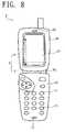
- FIG. 8is a front view of a portable telephone of a second embodiment
- FIG. 9is a front view showing the telephone with a second case thereof rotated through 90 degrees
- FIG. 10is a front view showing the telephone with its second case brought closer to a first case
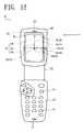
- FIG. 11is a front view of a portable telephone of a third embodiment
- FIG. 12is a front view showing the telephone with a second case thereof moved away from a first case
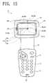
- FIG. 13is a perspective view showing the telephone with the second case thereof rotated through 90 degrees;
- FIG. 14is a perspective view showing the telephone with its second case brought closer to the first case
- FIG. 15is a front view of a conventional portable telephone.
- FIG. 16is a front view showing the telephone with a flip portion thereof rotated about a first pivot and a second pivot.
- the foldable portable telephone of the present inventionhas a television broadcast receiving function and a wireless communications function.
- the telephonehas a main body 1 , which comprises a first case 10 vertically elongated as shown in FIG. 1 , a second case 20 similarly vertically elongated, a hinge mechanism 30 for making the two cases 10 , 20 closable or openable, and a connecting mechanism 4 for making the two cases 10 , 20 rotatable and slidable relative to each other.
- the connecting mechanism 4comprises a pivot mechanism 5 for rotating the second case 20 relative to the first case 10 , and a slide mechanism 6 for slidingly moving the second case 20 relative to the first case 10 .
- the lower end of the second case 20is connected to the upper end of the first case 10 by the hinge mechanism 30 and the connecting mechanism 4 , whereby the first case 10 and the second case 20 are closable toward or openable from each other by the action of the hinge mechanism 30 .
- the first case 10has a flat rectangular front surface.
- the case 10has a plurality of manual keys 11 arranged on the front side, and a transmitter 12 disposed below the arrangement of keys 11 .
- the second case 20has a flat rectangular front surface.
- a rectangular display 21having a predetermined aspect ratio, with its long side positioned vertically in conformity with the vertically elongated shape of the main body 1 , and a receiver 22 disposed above the display 21 .
- the first case 10is connected to one rotatable end of the hinge mechanism 30 .
- a support plate 70Projecting from the other rotatable end of the mechanism 30 is a support plate 70 having a front surface and a rear surface which are parallel to the front surface of the second case 20 .
- a pair of engaging pins 71 , 71 in alignment with each otherare elastically supported on and retractably attached to the front and rear sides of the support plate 70 .
- an L-shaped compartment 23 for movably accommodating the support plate 70extends into the second case 20 from a lateral side wall 27 and end wall 28 thereof.
- the inner surfaces of the second case 20 defining the compartment 23 and opposed respectively to the front and rear surfaces of the support plate 70are provided with a pair of slide grooves 26 , 26 opposed to each other for guiding the sliding movement of the support plate 70 .
- a first bearing portion 24is formed at the lower end of each of the slide grooves 26 , 26 , and a second bearing portion 25 at the upper end thereof.
- the engaging pins 71 , 71 on the support plate 70are slidably fitted in the respective slide grooves 26 between the first bearing portions 24 , 24 and the second bearing portions 25 , 25 .
- the pivot mechanism 5comprises the pair of first bearing portions 24 , 24 of the compartment 23 and the pair of engaging pins 71 , 71 projecting from the respective front and rear sides of the support plate 70 .
- the second case 20is rotatable about the engaging pins 71 , 71 serving as pivots.
- the slide mechanism 6comprises the pair of slide grooves 26 , 26 formed in the inner surfaces of the second case 20 defining the support plate compartment 23 and the pair of engaging pins 71 , 71 projecting from the front and rear sides of the support plate 70 .
- the first case 10 and the second case 20are opened by the action of the hinge mechanism 30 as shown in FIG. 1 , whereby the screen of the display 21 is set in a vertically elongated screen position, and required information such as the telephone number of the incoming caller is presented on the screen of the display 21 .
- the second case 20 in its opened positionis pushed sideways as shown in FIG. 1 , whereby the second case 20 is rotated through 90 degrees about the engaging pins 71 , 71 by the action of the pivot mechanism 5 .
- the rotationbrings the display screen of the second case 20 from the vertically elongated screen position shown in FIG. 1 to a horizontally elongated position shown in FIG. 2 .
- the orientation of the image on the display 21 relative to the screen thereofis changed toward a direction 90 degrees different for the display to show images as oriented normally for the horizontally elongated screen.
- the engaging pins 71 , 71are positioned perpendicular to the surface of the second case 20 , the screen of the display 21 of the second case 20 is rotated on the same plane at this time.
- the display 21 of the second case 20 and the arrangement of manual keys 11 on the first case 10are therefore both positioned face-to-face with the user even after the rotation of the second case 20 .
- the second case 20is further pushed sideways as indicated by an arrow in FIG. 2 , with the display screen of the second case 20 in the horizontally elongated screen position illustrated. This releases the engaging pins 71 , 71 from soft holding engagement with the first bearing portions 24 , 24 , bringing the second case 20 closer to the first case 10 relative thereto by the action of the slide mechanism 6 as shown in FIG. 3 .
- the slide grooves 26 for guiding the movement of the second case 20are formed on planes parallel to the screen of the display 21 of the second case 20 . Accordingly, the screen of the display 21 of the second case 20 and the arrangement of manual keys 11 on the first case 10 are positioned face-to-face with the user even after the movement of the second case 20 .
- the screen of the display 21can be utilized in its entirety for displaying received images of television broadcasts. Since the display 21 and the arrangement of manual keys 11 are both positioned face-to-face with the user even while the user is watching the television broadcast, the user can readily manipulate keys while watching the television broadcast.
- the second case 20is brought close to the first case 10 , with both the screen of the display 21 of the second case 20 and the arrangement of key 11 on the first case 10 positioned as opposed to the user. This enables the user to watch the television broadcast on the main body 1 as compacted widthwise thereof.
- FIGS. 8 to 10show a portable telephone of this embodiment, wherein a second case 20 is rotatable and slidable relative to the first case 10 by the same connecting mechanism 4 as in the first embodiment, whereas the main body 2 of this embodiment has no hinge mechanism.
- the first case 10 and the second case 20both vertically elongated, are attached to each other only by the connecting mechanism 4 .
- a support plate 70is attached to the upper end of the first case 10 , and engaging pins 71 , 71 projecting from the front side and rear side of the support plate 70 are slidably fitted in respective slide grooves 26 , 26 between first bearing portions 24 , 24 and second bearing portions 25 , 25 .
- the grooves 26 , 26are formed in the inner surfaces of the second case 20 which define a compartment 23 for accommodating the support plate. In this way, the same pivot mechanism 5 and slide mechanism 6 as in the first embodiment are provided.
- a display 21 of the second case 20moves on the same plane. This enables the user to watch the television broadcast on the display 21 with the received images presented on the entire screen thereof and to readily manipulate keys while watching the television broadcast.
- FIGS. 11 to 14show a portable telephone of this embodiment which has the same construction as the first embodiment except the construction for rotating and slidingly moving a second case 80 relative to a first case 10 by the action of a connecting mechanism 40 . Accordingly, a description will be given only of the construction for rotating and slidingly moving the second case 80 by the action of the connecting mechanism 40 . As to the other construction, like parts are designated by like reference numerals for the other construction and will not be described repeatedly.
- a support plate 72has a front surface and a rear surface which are parallel to the surface of the second case 80 and is attached to the upper end of the first case 10 .
- a pair of engaging pins 73 , 73 in alignment with each otherare elastically supported on and retractably attached to the front and rear sides of the support plate 72 .
- the second case 80is internally provided with a compartment 81 for movably accommodating the support plate 72 .
- the inner surfaces of the second case 80 defining the compartment 81 and opposed respectively to the front and rear surfaces of the support plate 72are provided with a pair of first slide grooves 85 , 85 opposed to each other for guiding the sliding movement of the support plate 72 .
- the first slide grooves 85 , 85extend longitudinally of the second case 80 and have first bearing portions 82 , 82 at their upper ends and second bearing portions 83 , 83 at their lower ends.
- the compartment-defining inner surfaces of the second case 80have a pair of second slide grooves 86 , 86 orthogonal to the first slide grooves 85 , 85 and each having the second bearing portion 83 as one end.
- a third bearing portion 84is formed at the other end of each second slide groove 86 .
- the engaging pins 73 , 73 on the support plate 72are slidably fitted in the first slide grooves 85 or the second slide grooves 86 between the first bearing portions 82 , 82 and the third bearing portions 84 , 84 .
- a pivot mechanism 50comprises the pair of second bearing portions 83 , 83 formed in the compartment-defining inner surface of the second case 80 , and the pair of engaging pins 73 , 73 projecting from the front and rear sides of the support plate 72 .
- the engaging pins 73 , 73are softly held in the second bearing portions 83 , 83 .
- the second case 80is rotatable about the pins 73 , 73 in this state.
- a slide mechanism 60comprises the pair of first slide grooves 85 , 85 and the pair of second slide grooves 86 , 86 which are formed in the compartment-defining inner surfaces of the second case 80 , and the pair of engaging pins 73 , 73 projecting from the front and rear sides of the support plate 72 .
- the second case 80When a television broadcast is to be watched using the portable telephone of the present embodiment, the second case 80 is first pulled away from the first case 10 with the main body 3 in a contracted state as shown in FIG. 11 . This releases the engaging pins 73 , 73 from the first bearing portions 82 , 82 , and the slide mechanism 60 acts to move the second case 80 to a position where the pins 73 , 73 are opposed to the second bearing portions 83 , 83 as shown in FIG. 12 .
- the second case 80 in the state shown in FIG. 12is pushed sideways as indicated by an arrow, whereby the case 80 is rotated through 90 degrees about the engaging pins 73 , 73 by the action of the pivot mechanism 50 .
- the rotationshifts the screen of the display 21 of the second case 80 from the vertically elongated screen position shown in FIG. 12 to the horizontally elongated screen position shown in FIG. 13 . Further the rotation changes the orientation of the image on the display 21 relative to the screen toward a direction 90 degrees different, permitting the display 21 to show images as positioned normally for the horizontally elongated screen.
- the engaging pins 73 , 73are positioned perpendicular to the surface of the second case 80 , the screen of the display 21 in the case 80 rotates on the same plane at this time. Consequently, the display 21 of the second case 80 and the arrangement of key 11 are both positioned face-to-face with the user even after the rotation.
- the second case 80is further pushed toward the first case 10 with the screen of the display 21 of the second case 80 set in the horizontally elongated position as seen in FIG. 13 .
- the first slide grooves 85 , 85 and the second slide grooves 86 , 86 for guiding the movement of the second case 80are formed on planes parallel to the screen of the display 21 of the second case 80 , so that the display screen of the case 80 and the arrangement of manual keys 11 on the first case 10 are positioned face-to-face with the user even after the case 80 is thus moved.
- the display 21moves on the same plane. This enables the user to view television broadcast images as presented on the entire screen of the display 21 and to readily manipulate keys while watching the television broadcast.
Landscapes
- Engineering & Computer Science (AREA)
- Signal Processing (AREA)
- Multimedia (AREA)
- Telephone Set Structure (AREA)
- Mobile Radio Communication Systems (AREA)
- Telephone Function (AREA)
Abstract
Description
Claims (4)
Applications Claiming Priority (2)
| Application Number | Priority Date | Filing Date | Title |
|---|---|---|---|
| JP2003002425AJP3796222B2 (en) | 2003-01-08 | 2003-01-08 | Portable wireless terminal |
| JP2003-002425 | 2003-01-08 |
Publications (2)
| Publication Number | Publication Date |
|---|---|
| US20040137940A1 US20040137940A1 (en) | 2004-07-15 |
| US7194290B2true US7194290B2 (en) | 2007-03-20 |
Family
ID=32708860
Family Applications (1)
| Application Number | Title | Priority Date | Filing Date |
|---|---|---|---|
| US10/743,411Expired - Fee RelatedUS7194290B2 (en) | 2003-01-08 | 2003-12-23 | Portable wireless terminal device |
Country Status (2)
| Country | Link |
|---|---|
| US (1) | US7194290B2 (en) |
| JP (1) | JP3796222B2 (en) |
Cited By (19)
| Publication number | Priority date | Publication date | Assignee | Title |
|---|---|---|---|---|
| US20050141099A1 (en)* | 2003-12-26 | 2005-06-30 | Samsung Electronics Co., Ltd. | Appearing and disappearing type image pickup device |
| US20060023102A1 (en)* | 2004-07-22 | 2006-02-02 | Hiroki Ueno | Imaging device |
| US20060067680A1 (en)* | 2004-09-30 | 2006-03-30 | Microtek International Inc. | Portable image capturing device |
| US20060121852A1 (en)* | 2004-12-03 | 2006-06-08 | Samsung Electronics Co., Ltd. | Portable apparatus |
| US20060199606A1 (en)* | 2005-03-02 | 2006-09-07 | Sharp Kabushiki Kaisha | Folding cellular phone |
| USD566082S1 (en)* | 2005-12-22 | 2008-04-08 | Samsung Electronics Co., Ltd. | Mobile phone |
| US20080151481A1 (en)* | 2006-09-28 | 2008-06-26 | Fujifilm Corporation | Portable device |
| USD583791S1 (en)* | 2007-12-28 | 2008-12-30 | Samsung Electronics Co., Ltd. | Mobile phone |
| USD583793S1 (en)* | 2008-02-04 | 2008-12-30 | Samsung Electronics Co., Ltd. | Mobile phone |
| US20100151902A1 (en)* | 2008-12-15 | 2010-06-17 | Nokia Corporation | Method and Apparatus for Rotating a First and/or Second Portion of an Electronic Device |
| USD624107S1 (en)* | 2009-06-05 | 2010-09-21 | Freedom Scientific, Inc. | Hand held multi position magnifier camera |
| US20100302435A1 (en)* | 2009-05-29 | 2010-12-02 | Motorola, Inc. | Pivoting Structure Coupled to a Rotatable Housing Structure |
| US20110025908A1 (en)* | 2009-07-29 | 2011-02-03 | Hon Hai Precision Industry Co., Ltd. | Portable electronic device with slidable image capturing assembly |
| US20110286158A1 (en)* | 2010-05-20 | 2011-11-24 | Fih (Hong Kong) Limited | Rotating mechanism and electronic device using same |
| US20110308994A1 (en)* | 2008-06-24 | 2011-12-22 | Chuan Hung Lin | Protection Device for Memory Module |
| CN102668521A (en)* | 2009-11-09 | 2012-09-12 | 夏普株式会社 | Mobile terminal |
| CN104238653A (en)* | 2013-06-20 | 2014-12-24 | 联想(北京)有限公司 | Locking device and electronic equipment |
| US20160044808A1 (en)* | 2014-08-07 | 2016-02-11 | Mitsubishi Steel Mfg. Co., Ltd. | Opening and closing device, and electronic device |
| US10931803B2 (en)* | 2019-05-25 | 2021-02-23 | Shenzhen Xgear Technology Co., Ltd. | Mobile phone bracket with liftable panel |
Families Citing this family (46)
| Publication number | Priority date | Publication date | Assignee | Title |
|---|---|---|---|---|
| US6839576B2 (en)* | 2002-12-30 | 2005-01-04 | Motorola, Inc. | Multiple axis hinge assembly |
| JP4192024B2 (en)* | 2003-04-17 | 2008-12-03 | 加藤電機株式会社 | Mounting device for portable terminal |
| US7149557B2 (en)* | 2003-05-12 | 2006-12-12 | Siemens Communications, Inc. | Mobile communication device having extendable display |
| USD508029S1 (en)* | 2003-07-23 | 2005-08-02 | Lg Electronics Inc. | Mobile phone |
| KR100694258B1 (en)* | 2003-07-25 | 2007-03-14 | 엘지전자 주식회사 | Slide type mobile terminal |
| US8155718B2 (en) | 2003-09-03 | 2012-04-10 | Samsung Electronics Co., Ltd. | Sliding/hinge apparatus for sliding/rotating type mobile terminals |
| US7529571B2 (en) | 2003-09-03 | 2009-05-05 | Samsung Electronics Co., Ltd. | Sliding/hinge apparatus for sliding/rotating type mobile terminals |
| TWI233743B (en)* | 2004-03-05 | 2005-06-01 | Benq Corp | Hand-held electronic device and input method thereof |
| CN101707676B (en)* | 2004-03-08 | 2012-05-30 | 夏普株式会社 | Information communication terminal device and control method thereof |
| USD512395S1 (en)* | 2004-04-06 | 2005-12-06 | Samsung Electronics Co., Ltd. | Cellular phone |
| USD501838S1 (en)* | 2004-05-05 | 2005-02-15 | Samsung Electronics Co., Ltd. | Portable telephone |
| USD511509S1 (en)* | 2004-06-07 | 2005-11-15 | Samsung Electronics Co., Ltd. | Cellular phone |
| JPWO2006038499A1 (en)* | 2004-10-01 | 2008-07-31 | シャープ株式会社 | Mobile information terminal |
| JP4522233B2 (en) | 2004-11-17 | 2010-08-11 | パナソニック株式会社 | Mobile device |
| US7580518B2 (en)* | 2004-12-01 | 2009-08-25 | Motorola, Inc. | Dual-axes hinge part for hinged components |
| US7499540B2 (en) | 2004-12-30 | 2009-03-03 | Motorola, Inc. | Device having pivotable hinges |
| USD518812S1 (en)* | 2005-01-03 | 2006-04-11 | Samsung Electronics Co., Ltd. | Cellular phone |
| JP2006191438A (en)* | 2005-01-07 | 2006-07-20 | Matsushita Electric Ind Co Ltd | Mobile device |
| CN100477894C (en)* | 2005-02-22 | 2009-04-08 | 华硕电脑股份有限公司 | Rotary sliding module of display and mobile device adopting same |
| US20060270469A1 (en)* | 2005-05-25 | 2006-11-30 | Jon Godston | Wireless communication device and method of operation thereof |
| JP4548238B2 (en)* | 2005-06-20 | 2010-09-22 | パナソニック株式会社 | Switchgear and electronic device using the same |
| KR100726468B1 (en)* | 2005-06-27 | 2007-06-11 | (주)케이티에프테크놀로지스 | Hinge device and portable terminal using same |
| US7904125B2 (en)* | 2005-08-26 | 2011-03-08 | Lg Electronics Inc. | Slide module for portable terminal |
| KR100751940B1 (en)* | 2005-10-21 | 2007-08-24 | 엘지전자 주식회사 | Slide module and portable terminal having the slide module |
| TWI283982B (en)* | 2005-11-17 | 2007-07-11 | Benq Corp | Electronic device with movable and rotatable upper and lower housings |
| BRPI0618862A2 (en) | 2005-11-22 | 2011-09-13 | Sharp Kk | mobile phone |
| CN100493106C (en)* | 2006-01-26 | 2009-05-27 | 宏达国际电子股份有限公司 | Dynamic sliding module and its electronic device |
| US20070171195A1 (en) | 2006-01-26 | 2007-07-26 | Samsung Electronics Co., Ltd. | Sliding/swing-type portable terminal capable of positioning liquid crystal display at center portion thereof and method of using the same |
| CN101375583B (en) | 2006-03-29 | 2011-08-03 | 夏普株式会社 | mobile phone |
| US8243021B2 (en)* | 2006-03-31 | 2012-08-14 | Intel Corporation | Slide and rotate display configurations for a handheld computing device |
| US7846027B2 (en)* | 2006-05-30 | 2010-12-07 | Nokia Corporation | Handheld electronic devices |
| WO2008053610A1 (en)* | 2006-11-05 | 2008-05-08 | Toyo Sangyo Co., Ltd. | Mobile telephone |
| TWM312852U (en)* | 2006-11-07 | 2007-05-21 | Altek Corp | Digital image capturing device with a slidable LCD |
| US7996051B2 (en)* | 2007-02-21 | 2011-08-09 | Sony Ericsson Mobile Communications Ab | Wireless communications device with hinge |
| US7970444B2 (en)* | 2007-02-28 | 2011-06-28 | Sony Ericsson Mobile Communications Ab | Pivoting mobile terminal |
| JP4416804B2 (en) | 2007-03-26 | 2010-02-17 | シャープ株式会社 | Mobile device |
| JP4693069B2 (en)* | 2008-03-31 | 2011-06-01 | 日本電気株式会社 | Sliding / rotating mounting unit and mobile phone using the same |
| JP5073563B2 (en)* | 2008-04-10 | 2012-11-14 | 株式会社山本精密 | Case mutual connection unit and portable terminal |
| US20100016038A1 (en)* | 2008-07-15 | 2010-01-21 | Sony Ericsson Mobile Communications Ab | Portable communication device having an open channel hinge assembly |
| EP2309705A4 (en)* | 2008-07-28 | 2014-06-04 | Sharp Kk | Mobile terminal |
| JP5354184B2 (en)* | 2009-04-03 | 2013-11-27 | 日本電気株式会社 | Rotating unit and mobile phone |
| JP5561771B2 (en) | 2009-08-28 | 2014-07-30 | Necカシオモバイルコミュニケーションズ株式会社 | Device provided with housing and portable device |
| TWI439215B (en)* | 2010-05-28 | 2014-05-21 | Asustek Comp Inc | Docking station and electronic apparatus using the same |
| WO2014017202A1 (en)* | 2012-07-23 | 2014-01-30 | シャープ株式会社 | Display device |
| CN108900661A (en)* | 2018-06-08 | 2018-11-27 | Oppo广东移动通信有限公司 | Electronic device and control method thereof |
| CN112073564A (en)* | 2019-05-25 | 2020-12-11 | 长沙赛鲸电子科技有限公司 | A mobile phone bracket with a panel that can be lifted and lowered |
Citations (8)
| Publication number | Priority date | Publication date | Assignee | Title |
|---|---|---|---|---|
| JPH0578077A (en) | 1991-09-20 | 1993-03-30 | Mitsubishi Electric Corp | Entrance / exit device for curved man conveyor |
| JPH11215217A (en) | 1998-01-23 | 1999-08-06 | Toshiba Corp | Portable information terminal |
| JP3088157B2 (en) | 1991-11-25 | 2000-09-18 | 積水化学工業株式会社 | building |
| JP2001156893A (en) | 1999-11-29 | 2001-06-08 | Nec Saitama Ltd | Display system and its method for communication apparatus |
| US20010004269A1 (en)* | 1999-12-14 | 2001-06-21 | Junichiro Shibata | Portable terminal |
| US20030064758A1 (en)* | 2001-09-28 | 2003-04-03 | Nec Corporation | Foldable portable information terminal |
| JP2003338866A (en) | 2002-05-22 | 2003-11-28 | Fujitsu Ltd | Mobile phone |
| JP2004134999A (en) | 2002-10-09 | 2004-04-30 | Matsushita Electric Ind Co Ltd | Mobile communication terminal |
Family Cites Families (9)
| Publication number | Priority date | Publication date | Assignee | Title |
|---|---|---|---|---|
| JPH0578077U (en)* | 1992-03-25 | 1993-10-22 | 東京電子工業株式会社 | Portable magnifying reader with rotating mechanism on display unit |
| JP2002135380A (en)* | 2000-10-27 | 2002-05-10 | Matsushita Electric Ind Co Ltd | Foldable portable electronic devices |
| KR100470172B1 (en)* | 2001-06-22 | 2005-02-04 | 주식회사 임팩트라 | Mobile Station having Display Part Convertible Vertical into Horizontal |
| JP3770146B2 (en)* | 2001-10-29 | 2006-04-26 | 三菱電機株式会社 | Portable information terminal |
| KR100486611B1 (en)* | 2001-12-18 | 2005-05-03 | 주식회사 팬택앤큐리텔 | A personal mobile telephone haivng a LCD apparatus being capable of rotating |
| JP3088157U (en)* | 2002-02-25 | 2002-08-30 | 株式会社ゴールドライフ | Mobile phone |
| JP4061473B2 (en)* | 2002-04-26 | 2008-03-19 | 日本電気株式会社 | Folding mobile phone |
| JP3940640B2 (en)* | 2002-06-26 | 2007-07-04 | 京セラ株式会社 | Portable radio |
| JP3872390B2 (en)* | 2002-07-24 | 2007-01-24 | 京セラ株式会社 | Mobile terminal device |
- 2003
- 2003-01-08JPJP2003002425Apatent/JP3796222B2/ennot_activeExpired - Fee Related
- 2003-12-23USUS10/743,411patent/US7194290B2/ennot_activeExpired - Fee Related
Patent Citations (9)
| Publication number | Priority date | Publication date | Assignee | Title |
|---|---|---|---|---|
| JPH0578077A (en) | 1991-09-20 | 1993-03-30 | Mitsubishi Electric Corp | Entrance / exit device for curved man conveyor |
| JP3088157B2 (en) | 1991-11-25 | 2000-09-18 | 積水化学工業株式会社 | building |
| JPH11215217A (en) | 1998-01-23 | 1999-08-06 | Toshiba Corp | Portable information terminal |
| JP2001156893A (en) | 1999-11-29 | 2001-06-08 | Nec Saitama Ltd | Display system and its method for communication apparatus |
| US20010004269A1 (en)* | 1999-12-14 | 2001-06-21 | Junichiro Shibata | Portable terminal |
| JP2001169166A (en) | 1999-12-14 | 2001-06-22 | Nec Corp | Portable terminal |
| US20030064758A1 (en)* | 2001-09-28 | 2003-04-03 | Nec Corporation | Foldable portable information terminal |
| JP2003338866A (en) | 2002-05-22 | 2003-11-28 | Fujitsu Ltd | Mobile phone |
| JP2004134999A (en) | 2002-10-09 | 2004-04-30 | Matsushita Electric Ind Co Ltd | Mobile communication terminal |
Cited By (28)
| Publication number | Priority date | Publication date | Assignee | Title |
|---|---|---|---|---|
| US20050141099A1 (en)* | 2003-12-26 | 2005-06-30 | Samsung Electronics Co., Ltd. | Appearing and disappearing type image pickup device |
| US7483074B2 (en)* | 2003-12-26 | 2009-01-27 | Samsung Electronics Co., Ltd. | Appearing and disappearing type image pickup device |
| US20060023102A1 (en)* | 2004-07-22 | 2006-02-02 | Hiroki Ueno | Imaging device |
| US20060067680A1 (en)* | 2004-09-30 | 2006-03-30 | Microtek International Inc. | Portable image capturing device |
| US20060121852A1 (en)* | 2004-12-03 | 2006-06-08 | Samsung Electronics Co., Ltd. | Portable apparatus |
| US7587226B2 (en) | 2005-03-02 | 2009-09-08 | Sharp Kabushiki Kaisha | Folding cellular phone |
| US20060199606A1 (en)* | 2005-03-02 | 2006-09-07 | Sharp Kabushiki Kaisha | Folding cellular phone |
| USD566082S1 (en)* | 2005-12-22 | 2008-04-08 | Samsung Electronics Co., Ltd. | Mobile phone |
| US20080151481A1 (en)* | 2006-09-28 | 2008-06-26 | Fujifilm Corporation | Portable device |
| US7856258B2 (en)* | 2006-09-28 | 2010-12-21 | Fujifilm Corporation | Portable device |
| USD583791S1 (en)* | 2007-12-28 | 2008-12-30 | Samsung Electronics Co., Ltd. | Mobile phone |
| USD583793S1 (en)* | 2008-02-04 | 2008-12-30 | Samsung Electronics Co., Ltd. | Mobile phone |
| US20110308994A1 (en)* | 2008-06-24 | 2011-12-22 | Chuan Hung Lin | Protection Device for Memory Module |
| US20100151902A1 (en)* | 2008-12-15 | 2010-06-17 | Nokia Corporation | Method and Apparatus for Rotating a First and/or Second Portion of an Electronic Device |
| US20100302435A1 (en)* | 2009-05-29 | 2010-12-02 | Motorola, Inc. | Pivoting Structure Coupled to a Rotatable Housing Structure |
| US8179473B2 (en)* | 2009-05-29 | 2012-05-15 | Motorola Mobility, Inc. | Pivoting structure coupled to a rotatable housing structure |
| USD624107S1 (en)* | 2009-06-05 | 2010-09-21 | Freedom Scientific, Inc. | Hand held multi position magnifier camera |
| US8248521B2 (en)* | 2009-07-29 | 2012-08-21 | Hon Hai Precision Industry Co., Ltd. | Portable electronic device with slidable image capturing assembly |
| US20110025908A1 (en)* | 2009-07-29 | 2011-02-03 | Hon Hai Precision Industry Co., Ltd. | Portable electronic device with slidable image capturing assembly |
| CN102668521A (en)* | 2009-11-09 | 2012-09-12 | 夏普株式会社 | Mobile terminal |
| CN102668521B (en)* | 2009-11-09 | 2014-08-27 | 夏普株式会社 | portable terminal |
| US20110286158A1 (en)* | 2010-05-20 | 2011-11-24 | Fih (Hong Kong) Limited | Rotating mechanism and electronic device using same |
| US8270160B2 (en)* | 2010-05-20 | 2012-09-18 | Shenzhen Futaihong Precision Industry Co., Ltd. | Rotating mechanism and electronic device using same |
| CN104238653A (en)* | 2013-06-20 | 2014-12-24 | 联想(北京)有限公司 | Locking device and electronic equipment |
| CN104238653B (en)* | 2013-06-20 | 2017-11-07 | 联想(北京)有限公司 | A kind of locking device and electronic equipment |
| US20160044808A1 (en)* | 2014-08-07 | 2016-02-11 | Mitsubishi Steel Mfg. Co., Ltd. | Opening and closing device, and electronic device |
| US9413971B2 (en)* | 2014-08-07 | 2016-08-09 | Mitsubishi Steel Mfg. Co., Ltd. | Opening and closing device, and electronic device |
| US10931803B2 (en)* | 2019-05-25 | 2021-02-23 | Shenzhen Xgear Technology Co., Ltd. | Mobile phone bracket with liftable panel |
Also Published As
| Publication number | Publication date |
|---|---|
| JP2004215180A (en) | 2004-07-29 |
| US20040137940A1 (en) | 2004-07-15 |
| JP3796222B2 (en) | 2006-07-12 |
Similar Documents
| Publication | Publication Date | Title |
|---|---|---|
| US7194290B2 (en) | Portable wireless terminal device | |
| US7813775B2 (en) | Portable terminal foldable to form a triangular prism | |
| US8250712B2 (en) | Hinge device having a plurality of axes for a portable terminal and a connection member having the plurality of axes | |
| US7991442B2 (en) | Multiple opening and closing type mobile communication terminal | |
| US7916473B2 (en) | Portable terminal | |
| US8938276B2 (en) | Side sliding type mobile terminal | |
| US7809414B2 (en) | Portable information terminal, opening/closing operation method, and display method | |
| FI118073B (en) | Portable, at least two modes of use including foldable electronic device and hinged mechanism therefor | |
| US8509862B2 (en) | Rotation hinge apparatus for a portable terminal, dual hinge apparatus having the same, swing-type portable terminal, and sliding/rotation-type portable terminal | |
| US20060030381A1 (en) | Sliding/hinge apparatus for sliding/rotating type mobile terminals | |
| US7761123B2 (en) | Sliding and swing type portable terminal | |
| US20060037175A1 (en) | Dual axis hinge apparatus for portable terminal | |
| US20070293285A1 (en) | Portable terminal with hinge stopper | |
| US20070293286A1 (en) | Sliding module for mobile phone | |
| US8520378B2 (en) | Swing-type portable communication apparatus and hinge mechanism thereof | |
| US7974665B2 (en) | Dual-axis rotation folder-type mobile communication terminal and hinge device thereof | |
| KR100800711B1 (en) | Free stop hinge device of mobile terminal | |
| JP4210288B2 (en) | Portable wireless terminal | |
| KR100595674B1 (en) | Slide device of slide type portable terminal | |
| KR101134851B1 (en) | Mobile terminal | |
| KR100700567B1 (en) | Handheld terminal | |
| KR100648643B1 (en) | Sliding Terminal | |
| KR100631513B1 (en) | Rotating device for display unit of slide phone | |
| KR200370668Y1 (en) | Mobile terminal of slide type movable the right and left | |
| KR100664274B1 (en) | Horizontal rotating hinge device of mobile terminal |
Legal Events
| Date | Code | Title | Description |
|---|---|---|---|
| AS | Assignment | Owner name:SANYO ELECTRIC CO., LTD., JAPAN Free format text:ASSIGNMENT OF ASSIGNORS INTEREST;ASSIGNOR:MATSUNAMI, KANAKO;REEL/FRAME:014842/0681 Effective date:20031201 | |
| FEPP | Fee payment procedure | Free format text:PAYOR NUMBER ASSIGNED (ORIGINAL EVENT CODE: ASPN); ENTITY STATUS OF PATENT OWNER: LARGE ENTITY | |
| STCF | Information on status: patent grant | Free format text:PATENTED CASE | |
| AS | Assignment | Owner name:KYOCERA CORPORATION, JAPAN Free format text:ASSIGNMENT OF ASSIGNORS INTEREST;ASSIGNOR:SANYO ELECTRIC CO., LTD.;REEL/FRAME:022764/0839 Effective date:20081225 | |
| FPAY | Fee payment | Year of fee payment:4 | |
| FPAY | Fee payment | Year of fee payment:8 | |
| FEPP | Fee payment procedure | Free format text:MAINTENANCE FEE REMINDER MAILED (ORIGINAL EVENT CODE: REM.); ENTITY STATUS OF PATENT OWNER: LARGE ENTITY | |
| LAPS | Lapse for failure to pay maintenance fees | Free format text:PATENT EXPIRED FOR FAILURE TO PAY MAINTENANCE FEES (ORIGINAL EVENT CODE: EXP.); ENTITY STATUS OF PATENT OWNER: LARGE ENTITY | |
| STCH | Information on status: patent discontinuation | Free format text:PATENT EXPIRED DUE TO NONPAYMENT OF MAINTENANCE FEES UNDER 37 CFR 1.362 | |
| FP | Lapsed due to failure to pay maintenance fee | Effective date:20190320 |