US7193826B2 - Motor disconnect arrangement for a variable speed drive - Google Patents
Motor disconnect arrangement for a variable speed driveDownload PDFInfo
- Publication number
- US7193826B2 US7193826B2US10/789,327US78932704AUS7193826B2US 7193826 B2US7193826 B2US 7193826B2US 78932704 AUS78932704 AUS 78932704AUS 7193826 B2US7193826 B2US 7193826B2
- Authority
- US
- United States
- Prior art keywords
- inverter
- motors
- compressors
- motor
- inverters
- Prior art date
- Legal status (The legal status is an assumption and is not a legal conclusion. Google has not performed a legal analysis and makes no representation as to the accuracy of the status listed.)
- Expired - Lifetime, expires
Links
Images


Classifications
- H—ELECTRICITY
- H02—GENERATION; CONVERSION OR DISTRIBUTION OF ELECTRIC POWER
- H02H—EMERGENCY PROTECTIVE CIRCUIT ARRANGEMENTS
- H02H7/00—Emergency protective circuit arrangements specially adapted for specific types of electric machines or apparatus or for sectionalised protection of cable or line systems, and effecting automatic switching in the event of an undesired change from normal working conditions
- H02H7/08—Emergency protective circuit arrangements specially adapted for specific types of electric machines or apparatus or for sectionalised protection of cable or line systems, and effecting automatic switching in the event of an undesired change from normal working conditions for dynamo-electric motors
- H02H7/0833—Emergency protective circuit arrangements specially adapted for specific types of electric machines or apparatus or for sectionalised protection of cable or line systems, and effecting automatic switching in the event of an undesired change from normal working conditions for dynamo-electric motors for electric motors with control arrangements
Definitions
- the present inventionrelates generally to variable speed drives. More specifically, the present invention relates to an arrangement for disconnecting or removing a failed motor from a variable speed drive that has multiple independent inverter outputs.
- Many water chiller or refrigeration applicationsuse multiple refrigeration circuits, i.e., two or more refrigeration circuits, each having one or more compressors dedicated to the refrigeration circuit.
- One purpose of the multiple or redundant refrigerant circuits and compressorsis to provide improved reliability of the overall system by having one or more refrigerant circuits and compressors remain operational to provide a reduced level of cooling capacity in the event that a refrigerant circuit and/or compressor fails and can no longer provide cooling capacity.
- the corresponding compressor motor for each compressor of a refrigeration circuitcan be connected to the AC power grid at the system location.
- the connection of each compressor motor to the power gridpermits the remaining refrigerant circuits and compressors to remain operational even if one refrigerant circuit and/or compressor has a failure.
- a drawback to connecting the compressor motors to the power gridis that all of the motors are provided only one input voltage and frequency, and thus, can generate only one output speed.
- variable speed drivecan be inserted between the system power grid and the motor to provide the motor with power at a variable frequency and variable voltage.
- variable speed operation of the motorscan be obtained by providing a corresponding variable speed drive for each compressor motor or by connecting all of the compressor motors in parallel to the inverter output of a variable speed drive.
- One drawback to connecting the compressor motors in parallel to the single inverter output of the variable speed driveis that a fault or failure of one of the motors may disable the variable speed drive and thus prevent the other motors connected to the variable speed drive from operating the remaining compressors on the chiller system.
- This disabling of the other motors connected to the variable speed drivedefeats the function of the redundant refrigerant circuits because all of the refrigerant circuits are disabled as a result of the disabling of the motors and the variable speed drive.
- One embodiment of the present inventionis directed to a drive system for a plurality of motors having a variable speed drive and a plurality of connecting mechanisms connected in series with the variable speed drive.
- the variable speed driveincludes a converter stage to convert an AC voltage to a DC voltage, a DC link stage to filter and store energy from the converter stage, and an inverter stage having a plurality of inverters electrically connected in parallel to the DC link stage.
- the converter stageis configured to be electrically connectable to an AC power source.
- the DC link stageis electrically connected to the converter stage.
- Each inverter of the plurality of invertersis configured to convert a DC voltage to an AC voltage to power a corresponding motor of the plurality of motors and operates substantially independently of other inverters of the plurality of inverters.
- Each connecting mechanism of the plurality of connecting mechanismsis connected in series between an inverter of the plurality of inverters and a corresponding motor of the plurality of motors.
- Each connecting mechanismis configured to disconnect the inverter from the corresponding motor in response to receiving a control signal.
- Another embodiment of the present inventionis directed to a chiller system having a plurality of compressors incorporated into at least one refrigerant circuit.
- Each refrigerant circuithas at least one compressor, a condenser arrangement and an evaporator arrangement connected in a closed refrigerant loop.
- a corresponding motordrives each compressor of the plurality of compressors.
- a variable speed drivepowers the corresponding motors of the plurality of compressors and includes a converter stage, a DC link stage and an inverter stage.
- the inverter stagehas a plurality of inverters each electrically connected in parallel to the DC link stage and each powering a corresponding motor of a compressor of the plurality of compressors.
- the chiller systemalso includes a plurality of contactors.
- Each contactor of the plurality of contactorsis connected in series between an inverter of the plurality of inverters and a corresponding motor of a compressor of the plurality of compressors and is configured to enable or disable a connection between the inverter and the corresponding motor of a compressor of the plurality of compressors in response to receiving a control signal.
- Still another embodiment of the present inventionis directed to a drive system for a multiple compressor chiller system having a plurality of motors.
- the drive systemincluding a variable speed drive having a converter stage to convert an AC voltage to a DC voltage, a DC link stage to filter and store energy from the converter stage, and an inverter stage having a plurality of inverters electrically connected in parallel to the DC link stage.
- the converter stageis configured to be electrically connectable to an AC power source.
- the DC link stageis electrically connected to the converter stage.
- Each inverter of the plurality of invertersis configured to convert a DC voltage to an AC voltage to power a corresponding motor of the plurality of motors and operates substantially independently of other inverters of the plurality of inverters.
- the drive systemalso includes means for isolating a motor of the plurality motor from other motors of the plurality of motors in response to detecting a fault condition in the motor of the plurality of motors.
- One advantage of the present inventionis that it can isolate a failed motor connected to a variable speed drive without affecting operation of other motors connected to the variable speed drive.
- Another advantage of the present inventionis that it can be used to reliably and cost-effectively drive multiple motors at variable speeds.
- FIG. 1illustrates a general application of the present invention.
- FIG. 3illustrates an embodiment of the present invention used in a refrigeration or chiller system.
- FIG. 1illustrates generally an application of the present invention.
- An AC power source 102supplies a variable speed drive (VSD) 104 , which powers a plurality of motors 106 .
- VSDvariable speed drive
- a plurality of contactors 108 or other connect/disconnect means or devicesare connected in series between the VSD 104 and the plurality of motors 106 .
- the motors 106are preferably used to drive corresponding compressors of a refrigeration or chiller system (see FIG. 3 ).
- the AC power source 102provides single phase or multi-phase (e.g., three phase), fixed voltage, and fixed frequency AC power to the VSD 104 from an AC power grid or distribution system that is present at a site.
- the AC power source 102preferably can supply an AC voltage or line voltage of 200 V, 230 V, 380 V, 460 V, or 600 V at a line frequency of 50 Hz or 60 Hz to the VSD 104 , depending on the corresponding AC power grid.
- the VSD 104receives AC power having a particular fixed line voltage and fixed line frequency from the AC power source 102 and provides AC power to each of the motors 106 at desired voltages and desired frequencies, both of which can be varied to satisfy particular requirements.
- the VSD 104can provide AC power to each of the motors 106 that may have higher voltages and frequencies and lower voltages and frequencies than the rated voltage and frequency of each motor 106 .
- the VSD 104may again provide higher and lower frequencies but only the same or lower voltages than the rated voltage and frequency of each motor 106 .
- a contactor 108is connected in series between each output of the VSD 104 and its corresponding motor 106 to disconnect, isolate or remove that motor 106 from the VSD 104 in the event of a failure of the motor 106 . By removing a failed motor 106 from the VSD 104 , the other motors 106 connected to the VSD 104 can continue to operate normally.
- a microprocessor, controller or control panel 110is used to control the contactors 108 by sending signals (or not sending signals) to the contactors 108 that energize and de-energize the contactors 108 in response to particular system and motor 106 conditions as detected or sensed by sensors, detectors, probes or other similar devices.
- the contactors 108can have normally open contacts that are closed (energized) by the control panel 110 during operation of the motors 106 . If the control panel 110 detects a fault, short, ground or other anomalous condition in a motor 106 (or possibly the corresponding motor load), the control panel 110 can open (de-energize) the contacts in the contactor 108 in order to disconnect or isolate the failed motor 106 from the other motors 106 connected to the VSD 104 .
- the contactor 108can have any suitable arrangement of contacts or other connection devices or mechanisms so long as the contactor 108 can operate to disconnect or isolate a faulted motor 106 from the VSD 104 .
- the contacts in contactor 108are normally closed contacts that can be opened (energized) by the control panel 110 in response to the detection of a fault in the motor 106 .
- the VSD 104By disconnecting or isolating a damaged or failed motor 106 from the VSD 104 , in particular the DC bus of the DC link of the VSD 104 (see FIG. 2 ), the VSD 104 does not fail and can provide the appropriate power to the remaining motors 106 to permit the remaining motors 106 to operate normally.
- the contactors 108can be controlled by the control panel 110 to enable and disable operation of the motors 106 without the detection of a fault or failure in the motor 106 .
- the enabling and disabling of the motors 106can be used to control the corresponding motor loads connected to the motors 106 , e.g., compressors (see FIG. 3 ). For example, by disabling a motor 106 by de-energizing a contactor 108 , the corresponding motor load of the motor 106 is disabled, which may be desirable depending on the particular application of the motor load.
- the motor loadis a compressor as discussed above, then the disabling of the motor 106 and compressor can be used to adjust the capacity of the system that incorporates the motor 106 and compressor. Conversely, the enabling of a motor 106 and compressor by energizing contactor 108 can be used to increase the capacity of the corresponding system.
- the motors 106are preferably induction motors that are capable of being operated at variable speeds.
- the induction motorscan have any suitable pole arrangement including two poles, four poles or six poles. However, any suitable motor that can be operated at variable speeds can be used with the present invention.
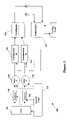
- FIG. 2illustrates schematically some of the components in one embodiment of the VSD 104 .
- the VSD 104can have three stages: a converter or rectifier stage 202 , a DC link stage 204 and an output stage having a plurality of inverters 206 .
- the converter 202converts the fixed line frequency, fixed line voltage AC power from the AC power source 102 into DC power.
- the converter 202can be in a rectifier arrangement composed of electronic switches that can only be turned on either by gating, when using silicon controlled rectifiers, or by being forward biased, when using diodes.
- the converter 202can be in a converter arrangement composed of electronic switches that can be gated both on and off, to generate a controlled DC voltage and to shape the input current signal to appear sinusoidal, if so desired.
- the converter arrangement of converter 202can have several different configurations including a boost conversion configuration (DC voltage varies from a value equal to the square root of two (2) times the RMS AC input voltage to a value greater than the square root of two (2) times the RMS AC input voltage), a buck conversion configuration (DC voltage varies from zero (0) to a value less than the square root of two (2) times the RMS AC input voltage), and a boost/buck configuration (DC voltage varies from zero (0) to a value that can be greater than or less than the square root of two (2) times the RMS AC input voltage).
- a boost conversion configurationDC voltage varies from a value equal to the square root of two (2) times the RMS AC input voltage to a value greater than the square root of two (2) times the RMS AC input voltage
- buck conversion configurationDC voltage varies from zero (0)
- the converter arrangement of converter 202has an additional level of flexibility over the rectifier arrangement, in that the AC power cannot only be rectified to DC power, but that the DC power level can also be controlled to a specific value.
- the DC link 204filters the DC power from the converter 202 and provides energy storage components such as capacitors and/or inductors.
- the inverters 206are connected in parallel on the DC link 204 and each inverter 206 converts the DC power from the DC link 204 into a variable frequency, variable voltage AC power for a corresponding motor 106 .
- the output of each inverter 206is then connected to a corresponding contactor or connecting mechanism 108 which is connected in series between the inverter 206 and the motor 106 .
- the inverters 206are jointly controlled by a control system such that each inverter 206 provides AC power at the same desired voltage and frequency to corresponding motors based on a common control signal or control instruction provided to the inverters 206 .
- the use of the contactors 108 to enable and disable the motors 106can be used with the joint control of the inverters 206 to provide a further level of control to the motors 106 .
- the inverters 206are individually controlled by a control system to permit each inverter 206 to provide AC power at different desired voltages and frequencies to corresponding motors 106 based on separate control signals or control instructions provided to each inverter 206 .
- This capabilitypermits the inverters 206 of the VSD 104 to more effectively satisfy motor 106 and system demands and loads independent of the requirements of other motors 106 and systems connected to other inverters 206 .
- one inverter 206can be providing full power to a motor 106
- another inverter 206is providing half power to another motor 106 .
- the control of the inverters 206 in either embodimentcan be by the control panel 110 or other suitable control device.
- each motor 106 to be powered by the VSD 104there is a corresponding inverter 206 in the output stage of the VSD 104 and contactor 108 connected between the motor 106 and the inverter 206 .
- the number of motors 106 that can be powered by the VSD 104is dependent upon the number of inverters 206 that are incorporated into the VSD 104 .
- VSD 104While it is preferred for the VSD 104 to have between 2 and 3 inverters 206 , it is to be understood that more than 3 inverters 206 can be used so long as the DC link 204 can provide and maintain the appropriate DC voltage to each of the inverters 206 .
- the converter 202can utilize diodes or silicon controlled rectifiers (SCRs) as the power switching mechanisms.
- the diodes and SCRscan provide the converter 202 with a large current surge capability and a low failure rate.
- the converter 202can utilize a diode or thyristor rectifier coupled to a boost DC/DC converter or a pulse width modulated boost rectifier to provide a boosted DC voltage to the DC link 204 in order to obtain an output voltage from the VSD 104 greater than the input voltage of the VSD 104 .
- the DC link 204can be composed of capacitors and inductors, which are passive devices that exhibit high reliability rates and very low failure rates.
- the inverters 206are power modules that can include power transistors or integrated bipolar power transistor (IGBT) power switches with diodes connected in parallel. Furthermore, it is to be understood that the VSD 104 can incorporate different components from those discussed above and shown in FIG. 2 so long as the inverters 206 of the VSD 104 can provide the motors 106 with appropriate output voltages and frequencies.
- IGBTintegrated bipolar power transistor
- the VSD 104can prevent large inrush currents from reaching the motors 106 during the startup of the motors 106 .
- the inverters 206 of the VSD 104can provide the AC power source 102 with power having about a unity power factor.
- the ability of the VSD 104 to adjust both the input voltage and input frequency received by the motor 106permits a system equipped with VSD 104 to be operated on a variety of foreign and domestic power grids without having to alter the motors 106 for different power sources.
- FIG. 3illustrates generally one embodiment of the present invention incorporated in a refrigeration system.
- the HVAC, refrigeration or liquid chiller system 300has two compressors incorporated in corresponding refrigerant circuits, but it is to be understood that the system 300 can have one refrigerant circuit or more than two refrigerant circuits for providing the desired system load and more than a single compressor for a corresponding refrigerant circuit.
- the system 300includes a first compressor 302 , a second compressor 303 , a condenser arrangement 308 , expansion devices, a water chiller or evaporator arrangement 310 and a control panel 110 .
- the control panel 110can include an analog to digital (A/D) converter, a microprocessor, a non-volatile memory, and an interface board to control operation of the refrigeration system 300 .
- the control panel 110can also be used to control the operation of the VSD 104 , the motors 106 , the contactors 108 and the compressors 302 and 303 .
- a conventional HVAC, refrigeration or liquid chiller system 300includes many other features that are not shown in FIG. 3 . These features have been purposely omitted to simplify the drawing for ease of illustration.
- the compressors 302 and 303compress a refrigerant vapor and deliver it to the condenser 308 .
- the compressors 302 and 303are preferably connected in separate refrigeration circuits, i.e., the refrigerant output by the compressors 302 and 303 are not mixed and travel in separate circuits through the system 300 before reentering the compressors 302 and 303 to begin another cycle.
- the separate refrigeration circuitspreferably use a single condenser housing 308 and a single evaporator housing 310 for the corresponding heat exchanges.
- the condenser housing 308 and evaporator housing 310maintain the separate refrigerant circuits either through a partition or other dividing means within the corresponding housing or with separate coil arrangements.
- the refrigerant output by the compressors 302 and 303can be combined into a single refrigerant circuit to travel through the system 300 before being separated to reenter the compressors 302 and 303 .
- the compressors 302 and 303are preferably screw compressors or centrifugal compressors, however the compressors can be any suitable type of compressor including reciprocating compressors, scroll compressors, rotary compressors or other type of compressor.
- the output capacity of the compressors 302 and 303can be based on the operating speed of the compressors 302 and 303 , which operating speed is dependent on the output speed of the motors 106 driven by the inverters 206 of the VSD 104 .
- the refrigerant vapor delivered to the condenser 308enters into a heat exchange relationship with a fluid, e.g., air or water, and undergoes a phase change to a refrigerant liquid as a result of the heat exchange relationship with the fluid.
- the condensed liquid refrigerant from condenser 308flows through corresponding expansion devices to an evaporator 310 .
- the evaporator 310can include connections for a supply line and a return line of a cooling load.
- a secondary liquidwhich is preferably water, but can be any other suitable secondary liquid, e.g., ethylene, calcium chloride brine or sodium chloride brine, travels into the evaporator 310 via a return line and exits the evaporator 310 via a supply line.
- the liquid refrigerant in the evaporator 310enters into a heat exchange relationship with the secondary liquid to chill the temperature of the secondary liquid.
- the refrigerant liquid in the evaporator 310undergoes a phase change to a refrigerant vapor as a result of the heat exchange relationship with the secondary liquid.
- the vapor refrigerant in the evaporator 310then returns to the compressors 302 and 303 to complete the cycle. It is to be understood that any suitable configuration of condenser 308 and evaporator 310 can be used in the system 300 , provided that the appropriate phase change of the refrigerant in the condenser 304 and evaporator 306 is obtained.
- control panel, microprocessor or controller 110in addition to controlling the contactors 108 , can provide control signals to the VSD 104 to control the operation of the VSD 104 , and particularly the operation of inverters 206 , (and possibly motors 106 ) to provide the optimal operational setting for the VSD 104 and motors 106 depending on the particular sensor readings received by the control panel 110 .
- control signalsto the VSD 104 to control the operation of the VSD 104 , and particularly the operation of inverters 206 , (and possibly motors 106 ) to provide the optimal operational setting for the VSD 104 and motors 106 depending on the particular sensor readings received by the control panel 110 .
- inverters 206and possibly motors 106
- the control panel 110can adjust the output voltage and frequency from the inverters 206 to correspond to changing conditions in the refrigeration system 300 , i.e., the control panel 110 can increase or decrease the output voltage and frequency of the inverters 206 of the VSD 104 in response to increasing or decreasing load conditions on the compressors 302 and 303 in order to obtain a desired operating speed of the motors 106 and a desired capacity of the compressors 302 and 303 .
Landscapes
- Control Of Multiple Motors (AREA)
Abstract
Description
Claims (24)
Priority Applications (2)
| Application Number | Priority Date | Filing Date | Title |
|---|---|---|---|
| US10/789,327US7193826B2 (en) | 2004-02-27 | 2004-02-27 | Motor disconnect arrangement for a variable speed drive |
| US11/688,105US20070151265A1 (en) | 2004-02-27 | 2007-03-19 | Startup control system and method for a multiple compressor chiller system |
Applications Claiming Priority (1)
| Application Number | Priority Date | Filing Date | Title |
|---|---|---|---|
| US10/789,327US7193826B2 (en) | 2004-02-27 | 2004-02-27 | Motor disconnect arrangement for a variable speed drive |
Related Child Applications (1)
| Application Number | Title | Priority Date | Filing Date |
|---|---|---|---|
| US11/688,105Continuation-In-PartUS20070151265A1 (en) | 2004-02-27 | 2007-03-19 | Startup control system and method for a multiple compressor chiller system |
Publications (2)
| Publication Number | Publication Date |
|---|---|
| US20050190511A1 US20050190511A1 (en) | 2005-09-01 |
| US7193826B2true US7193826B2 (en) | 2007-03-20 |
Family
ID=34887251
Family Applications (1)
| Application Number | Title | Priority Date | Filing Date |
|---|---|---|---|
| US10/789,327Expired - LifetimeUS7193826B2 (en) | 2004-02-27 | 2004-02-27 | Motor disconnect arrangement for a variable speed drive |
Country Status (1)
| Country | Link |
|---|---|
| US (1) | US7193826B2 (en) |
Cited By (14)
| Publication number | Priority date | Publication date | Assignee | Title |
|---|---|---|---|---|
| US20100033123A1 (en)* | 2008-08-08 | 2010-02-11 | Shunxin Zhou | System for realizing rotor variable frequency speed control asynchronously and simultaneously by driving multiple motors via one inverter |
| US20110072836A1 (en)* | 2009-09-30 | 2011-03-31 | Thermo Fisher Scientific (Asheville) Llc | Refrigeration system having a variable speed compressor |
| US20110072837A1 (en)* | 2009-09-30 | 2011-03-31 | Thermo Fisher Scientific (Asheville) Llc | Refrigeration system mounted within a deck |
| US20140253011A1 (en)* | 2005-11-04 | 2014-09-11 | Sky Climber Llc | Motor control system |
| US8925346B2 (en) | 2012-02-07 | 2015-01-06 | Thermo Fisher Scientific (Asheville) Llc | High performance freezer having cylindrical cabinet |
| US9318974B2 (en) | 2014-03-26 | 2016-04-19 | Solaredge Technologies Ltd. | Multi-level inverter with flying capacitor topology |
| US20170310234A1 (en)* | 2016-04-26 | 2017-10-26 | General Electric Company | Power converter topology for use in an energy storage system |
| US9941813B2 (en) | 2013-03-14 | 2018-04-10 | Solaredge Technologies Ltd. | High frequency multi-level inverter |
| US10256753B2 (en) | 2017-03-09 | 2019-04-09 | Regal Beloit America, Inc. | AC motor systems with drive circuits and methods of use |
| US10439540B1 (en) | 2018-03-29 | 2019-10-08 | Regal Beloit America, Inc. | Drive circuit for electric motors |
| US11196362B2 (en) | 2017-10-30 | 2021-12-07 | Annexair Inc. | System for controlling a plurality of synchronous permanent magnet electronically commutated motors |
| US11480373B2 (en)* | 2012-08-30 | 2022-10-25 | Johnson Controls Tyco IP Holdings LLP | Variable speed drive control for chiller coast-through |
| US11855563B2 (en) | 2018-04-16 | 2023-12-26 | Regal Beloit America, Inc. | Motor controllers and methods for controlling drive circuit bypass signals |
| US12244245B2 (en) | 2021-10-18 | 2025-03-04 | Carrier Corporation | Transport refrigeration system with paralleled inverters |
Families Citing this family (16)
| Publication number | Priority date | Publication date | Assignee | Title |
|---|---|---|---|---|
| US7164242B2 (en)* | 2004-02-27 | 2007-01-16 | York International Corp. | Variable speed drive for multiple loads |
| US7207183B2 (en)* | 2004-04-12 | 2007-04-24 | York International Corp. | System and method for capacity control in a multiple compressor chiller system |
| US7555912B2 (en)* | 2005-03-01 | 2009-07-07 | York International Corporation | System for precharging a DC link in a variable speed drive |
| US7619906B2 (en)* | 2005-03-01 | 2009-11-17 | York International Corporation | System for precharging a DC link in a variable speed drive |
| US7005829B2 (en)* | 2005-03-01 | 2006-02-28 | York International Corp. | System for precharging a DC link in a variable speed drive |
| US8096139B2 (en)* | 2005-10-17 | 2012-01-17 | Carrier Corporation | Refrigerant system with variable speed drive |
| US8144438B2 (en)* | 2008-10-03 | 2012-03-27 | General Electric Company | Motor control center communication system |
| US8353174B1 (en) | 2008-10-03 | 2013-01-15 | Johnson Controls Technology Company | Control method for vapor compression system |
| CN102884695B (en) | 2010-05-04 | 2016-03-30 | 江森自控科技公司 | variable speed drive |
| US9081052B2 (en)* | 2011-09-30 | 2015-07-14 | Hewlett-Packard Development Company, L.P. | Monitoring module and method for determining the status of electrical components |
| WO2013149639A1 (en)* | 2012-04-02 | 2013-10-10 | Siemens Aktiengesellschaft | Electrical drive arrangement |
| WO2014120651A1 (en)* | 2013-01-30 | 2014-08-07 | Trane International Inc. | Multiple load control for variable frequency drive harmonic mitigation |
| JP2015084622A (en)* | 2013-10-25 | 2015-04-30 | 三菱重工オートモーティブサーマルシステムズ株式会社 | Driving device and driving method for switching element; and vehicular air conditioner |
| KR102366592B1 (en)* | 2015-09-24 | 2022-02-23 | 엘지전자 주식회사 | Chiller |
| US20180287545A1 (en)* | 2017-04-03 | 2018-10-04 | Ge Energy Power Conversion Technology Limited | Dynamic Parameter Limiting Based on Asset Performance and Health Status |
| CN113555948B (en)* | 2021-06-26 | 2024-10-29 | 华为数字能源技术有限公司 | Power supply control system, power supply control method, and communication device |
Citations (54)
| Publication number | Priority date | Publication date | Assignee | Title |
|---|---|---|---|---|
| US2442021A (en) | 1944-11-16 | 1948-05-25 | Westinghouse Electric Corp | Sectionalized variable-speed drive |
| US3390320A (en) | 1966-06-13 | 1968-06-25 | Lorain Prod Corp | Transistor inverter for synchronized operation with a like paralleled inverter |
| US3621365A (en) | 1970-08-13 | 1971-11-16 | Garrett Corp | Parallel coupled static inverters |
| US3909687A (en) | 1974-03-05 | 1975-09-30 | Westinghouse Electric Corp | Flux control system for controlled induction motors |
| US4150425A (en) | 1978-02-09 | 1979-04-17 | Nasa | Module failure isolation circuit for paralleled inverters |
| US4151725A (en) | 1977-05-09 | 1979-05-01 | Borg-Warner Corporation | Control system for regulating large capacity rotating machinery |
| US4152902A (en) | 1976-01-26 | 1979-05-08 | Lush Lawrence E | Control for refrigeration compressors |
| GB1579045A (en) | 1976-11-19 | 1980-11-12 | Electric Power Res Inst | Variable speed drive unit for compressor of heat pump |
| JPS60102878A (en) | 1983-11-07 | 1985-06-07 | Nippon Electric Ind Co Ltd | Parallel redundancy synchronous operation type inverter |
| US4546423A (en) | 1982-02-23 | 1985-10-08 | Tokyo Shibaura Denki Kabushiki Kaisha | Multiple inverters with overcurrent and shoot-through protection |
| US4787211A (en) | 1984-07-30 | 1988-11-29 | Copeland Corporation | Refrigeration system |
| US4877388A (en) | 1986-08-11 | 1989-10-31 | Fanuc Ltd. | Mold clamping apparatus in an injection molding machine |
| US4958118A (en) | 1989-08-28 | 1990-09-18 | A. O. Smith Corporation | Wide range, self-starting single phase motor speed control |
| US5010287A (en) | 1988-02-24 | 1991-04-23 | Matsushita Electric Works, Ltd. | Induction motor control system |
| US5235504A (en) | 1991-03-15 | 1993-08-10 | Emerson Electric Co. | High power-factor converter for motor drives and power supplies |
| US5283708A (en)* | 1990-09-27 | 1994-02-01 | Allen-Bradley Company, Inc. | Overload current protection apparatus |
| US5350992A (en) | 1991-09-17 | 1994-09-27 | Micro-Trak Systems, Inc. | Motor control circuit |
| WO1995006973A1 (en) | 1993-08-31 | 1995-03-09 | Abb Industry Oy | Power supply arrangement for a multiple electric motor line drive |
| US5446645A (en) | 1992-02-18 | 1995-08-29 | Hitachi, Ltd. | Inverter apparatus and uinterruptible power supply using the same |
| US5488279A (en) | 1990-12-28 | 1996-01-30 | Sawafuji Electric Co., Ltd. | Dual power refrigerator |
| EP0695024A2 (en) | 1994-07-01 | 1996-01-31 | Sharp Kabushiki Kaisha | Air conditioning device |
| US5492273A (en) | 1992-05-27 | 1996-02-20 | General Electric Company | Heating ventilating and/or air conditioning system having a variable speed indoor blower motor |
| US5503248A (en) | 1994-04-06 | 1996-04-02 | Otis Elevator Company | Maintaining open loop current drive to linear induction motor |
| US5509504A (en) | 1994-04-06 | 1996-04-23 | Otis Elevator Company | Velocity regulated, open current loop, variable voltage, variable frequency, linear induction motor drive for an elevator car door |
| US5528114A (en) | 1992-11-27 | 1996-06-18 | Sanyo Electric Co., Ltd. | Apparatus for driving two motors |
| WO1997018420A1 (en) | 1995-10-26 | 1997-05-22 | Jdm, Ltd. | Variable speed liquid refrigerant pump |
| US5691625A (en)* | 1996-09-23 | 1997-11-25 | General Electric Company | Using sensed stator terminal voltages for determining alternator rotor position for cranking an engine |
| US5797729A (en)* | 1996-02-16 | 1998-08-25 | Aspen Systems, Inc. | Controlling multiple variable speed compressors |
| US5845509A (en) | 1997-09-26 | 1998-12-08 | Shaw; David N. | Variable speed parallel centrifugal compressors for HVAC and refrigeration systems |
| US5894736A (en) | 1996-04-11 | 1999-04-20 | York International Corporation | Methods and apparatuses for detecting surge in centrifugal compressors |
| US5896021A (en) | 1997-02-06 | 1999-04-20 | General Electric Company | Removal of moisture from induction motors |
| US6008616A (en) | 1994-12-12 | 1999-12-28 | Kabushiki Kaisha Meidensha | Pole change induction motor and control apparatus and method for the same |
| US6018957A (en) | 1998-12-07 | 2000-02-01 | Carrier Corporation | Method and apparatus for controlling beats and minimizing pulsation effects in multiple compressor installations |
| US6023137A (en)* | 1997-10-01 | 2000-02-08 | General Electric Company | Use of traction inverter for supplying power for non-traction applications |
| US6031738A (en) | 1998-06-16 | 2000-02-29 | Wisconsin Alumni Research Foundation | DC bus voltage balancing and control in multilevel inverters |
| EP1022844A2 (en) | 1999-01-19 | 2000-07-26 | Matsushita Electric Industrial Co., Ltd. | Power supply device and air conditioner using the same |
| US6124697A (en) | 1997-08-20 | 2000-09-26 | Wilkerson; Alan W. | AC inverter drive |
| EP1055885A2 (en) | 1999-05-25 | 2000-11-29 | Sharp Kabushiki Kaisha | Air conditioner |
| US6185946B1 (en) | 1999-05-07 | 2001-02-13 | Thomas B. Hartman | System for sequencing chillers in a loop cooling plant and other systems that employ all variable-speed units |
| US6229722B1 (en) | 1997-10-09 | 2001-05-08 | Kabushiki Kaisha Toshiba | Multiple inverter system |
| US6252751B1 (en)* | 1998-12-23 | 2001-06-26 | Hamilton Sundstrand Corporation | Method and apparatus for distributing alternating electrical current to motors via a direct current bus |
| US6325142B1 (en) | 1998-01-05 | 2001-12-04 | Capstone Turbine Corporation | Turbogenerator power control system |
| DE10047629A1 (en) | 2000-09-26 | 2002-04-11 | Linde Ag | Method for operating compressors in refrigeration and air-conditioning installations, involves using two-pole asynchronous motors to drive compressors |
| US6370888B1 (en) | 2000-08-31 | 2002-04-16 | Carrier Corporation | Method for controlling variable speed drive with chiller equipped with multiple compressors |
| US6408645B1 (en) | 2000-02-14 | 2002-06-25 | Hitachi Air Conditioning Systems, Co. Ltd. | Air-conditioner, outdoor unit and refrigeration unit |
| US6434960B1 (en) | 2001-07-02 | 2002-08-20 | Carrier Corporation | Variable speed drive chiller system |
| US6459606B1 (en) | 2001-09-27 | 2002-10-01 | York International Corporation | Control system and method for four-quadrant switches in three-phase PWM AC voltage regulators |
| US6459596B1 (en) | 2000-08-18 | 2002-10-01 | The United States Of America As Represented By The Secretary Of The Navy | Method and apparatus for a Reduced parts-counts multilevel rectifier |
| EP1271067A1 (en) | 2000-04-03 | 2003-01-02 | Daikin Industries, Ltd. | Air conditioner |
| US20030041605A1 (en) | 2001-08-31 | 2003-03-06 | Carrier Corporation | Twinning interface control box kit for twinned fan coils in dual heat pump or AC system |
| US20030098668A1 (en)* | 2001-11-27 | 2003-05-29 | York International Corporation | Control loop and method for variable speed drive ride - through capability improvement |
| US6579067B1 (en) | 2001-12-31 | 2003-06-17 | Carrier Corporation | Variable speed control of multiple compressors |
| EP1376842A1 (en) | 2002-06-19 | 2004-01-02 | Fanuc Ltd. | Motor driving controller. |
| US6804127B2 (en)* | 2002-11-19 | 2004-10-12 | Wilcon Inc. | Reduced capacitance AC/DC/AC power converter |
- 2004
- 2004-02-27USUS10/789,327patent/US7193826B2/ennot_activeExpired - Lifetime
Patent Citations (54)
| Publication number | Priority date | Publication date | Assignee | Title |
|---|---|---|---|---|
| US2442021A (en) | 1944-11-16 | 1948-05-25 | Westinghouse Electric Corp | Sectionalized variable-speed drive |
| US3390320A (en) | 1966-06-13 | 1968-06-25 | Lorain Prod Corp | Transistor inverter for synchronized operation with a like paralleled inverter |
| US3621365A (en) | 1970-08-13 | 1971-11-16 | Garrett Corp | Parallel coupled static inverters |
| US3909687A (en) | 1974-03-05 | 1975-09-30 | Westinghouse Electric Corp | Flux control system for controlled induction motors |
| US4152902A (en) | 1976-01-26 | 1979-05-08 | Lush Lawrence E | Control for refrigeration compressors |
| GB1579045A (en) | 1976-11-19 | 1980-11-12 | Electric Power Res Inst | Variable speed drive unit for compressor of heat pump |
| US4151725A (en) | 1977-05-09 | 1979-05-01 | Borg-Warner Corporation | Control system for regulating large capacity rotating machinery |
| US4150425A (en) | 1978-02-09 | 1979-04-17 | Nasa | Module failure isolation circuit for paralleled inverters |
| US4546423A (en) | 1982-02-23 | 1985-10-08 | Tokyo Shibaura Denki Kabushiki Kaisha | Multiple inverters with overcurrent and shoot-through protection |
| JPS60102878A (en) | 1983-11-07 | 1985-06-07 | Nippon Electric Ind Co Ltd | Parallel redundancy synchronous operation type inverter |
| US4787211A (en) | 1984-07-30 | 1988-11-29 | Copeland Corporation | Refrigeration system |
| US4877388A (en) | 1986-08-11 | 1989-10-31 | Fanuc Ltd. | Mold clamping apparatus in an injection molding machine |
| US5010287A (en) | 1988-02-24 | 1991-04-23 | Matsushita Electric Works, Ltd. | Induction motor control system |
| US4958118A (en) | 1989-08-28 | 1990-09-18 | A. O. Smith Corporation | Wide range, self-starting single phase motor speed control |
| US5283708A (en)* | 1990-09-27 | 1994-02-01 | Allen-Bradley Company, Inc. | Overload current protection apparatus |
| US5488279A (en) | 1990-12-28 | 1996-01-30 | Sawafuji Electric Co., Ltd. | Dual power refrigerator |
| US5235504A (en) | 1991-03-15 | 1993-08-10 | Emerson Electric Co. | High power-factor converter for motor drives and power supplies |
| US5350992A (en) | 1991-09-17 | 1994-09-27 | Micro-Trak Systems, Inc. | Motor control circuit |
| US5446645A (en) | 1992-02-18 | 1995-08-29 | Hitachi, Ltd. | Inverter apparatus and uinterruptible power supply using the same |
| US5492273A (en) | 1992-05-27 | 1996-02-20 | General Electric Company | Heating ventilating and/or air conditioning system having a variable speed indoor blower motor |
| US5528114A (en) | 1992-11-27 | 1996-06-18 | Sanyo Electric Co., Ltd. | Apparatus for driving two motors |
| WO1995006973A1 (en) | 1993-08-31 | 1995-03-09 | Abb Industry Oy | Power supply arrangement for a multiple electric motor line drive |
| US5509504A (en) | 1994-04-06 | 1996-04-23 | Otis Elevator Company | Velocity regulated, open current loop, variable voltage, variable frequency, linear induction motor drive for an elevator car door |
| US5503248A (en) | 1994-04-06 | 1996-04-02 | Otis Elevator Company | Maintaining open loop current drive to linear induction motor |
| EP0695024A2 (en) | 1994-07-01 | 1996-01-31 | Sharp Kabushiki Kaisha | Air conditioning device |
| US6008616A (en) | 1994-12-12 | 1999-12-28 | Kabushiki Kaisha Meidensha | Pole change induction motor and control apparatus and method for the same |
| WO1997018420A1 (en) | 1995-10-26 | 1997-05-22 | Jdm, Ltd. | Variable speed liquid refrigerant pump |
| US5797729A (en)* | 1996-02-16 | 1998-08-25 | Aspen Systems, Inc. | Controlling multiple variable speed compressors |
| US5894736A (en) | 1996-04-11 | 1999-04-20 | York International Corporation | Methods and apparatuses for detecting surge in centrifugal compressors |
| US5691625A (en)* | 1996-09-23 | 1997-11-25 | General Electric Company | Using sensed stator terminal voltages for determining alternator rotor position for cranking an engine |
| US5896021A (en) | 1997-02-06 | 1999-04-20 | General Electric Company | Removal of moisture from induction motors |
| US6124697A (en) | 1997-08-20 | 2000-09-26 | Wilkerson; Alan W. | AC inverter drive |
| US5845509A (en) | 1997-09-26 | 1998-12-08 | Shaw; David N. | Variable speed parallel centrifugal compressors for HVAC and refrigeration systems |
| US6023137A (en)* | 1997-10-01 | 2000-02-08 | General Electric Company | Use of traction inverter for supplying power for non-traction applications |
| US6229722B1 (en) | 1997-10-09 | 2001-05-08 | Kabushiki Kaisha Toshiba | Multiple inverter system |
| US6325142B1 (en) | 1998-01-05 | 2001-12-04 | Capstone Turbine Corporation | Turbogenerator power control system |
| US6031738A (en) | 1998-06-16 | 2000-02-29 | Wisconsin Alumni Research Foundation | DC bus voltage balancing and control in multilevel inverters |
| US6018957A (en) | 1998-12-07 | 2000-02-01 | Carrier Corporation | Method and apparatus for controlling beats and minimizing pulsation effects in multiple compressor installations |
| US6252751B1 (en)* | 1998-12-23 | 2001-06-26 | Hamilton Sundstrand Corporation | Method and apparatus for distributing alternating electrical current to motors via a direct current bus |
| EP1022844A2 (en) | 1999-01-19 | 2000-07-26 | Matsushita Electric Industrial Co., Ltd. | Power supply device and air conditioner using the same |
| US6185946B1 (en) | 1999-05-07 | 2001-02-13 | Thomas B. Hartman | System for sequencing chillers in a loop cooling plant and other systems that employ all variable-speed units |
| EP1055885A2 (en) | 1999-05-25 | 2000-11-29 | Sharp Kabushiki Kaisha | Air conditioner |
| US6408645B1 (en) | 2000-02-14 | 2002-06-25 | Hitachi Air Conditioning Systems, Co. Ltd. | Air-conditioner, outdoor unit and refrigeration unit |
| EP1271067A1 (en) | 2000-04-03 | 2003-01-02 | Daikin Industries, Ltd. | Air conditioner |
| US6459596B1 (en) | 2000-08-18 | 2002-10-01 | The United States Of America As Represented By The Secretary Of The Navy | Method and apparatus for a Reduced parts-counts multilevel rectifier |
| US6370888B1 (en) | 2000-08-31 | 2002-04-16 | Carrier Corporation | Method for controlling variable speed drive with chiller equipped with multiple compressors |
| DE10047629A1 (en) | 2000-09-26 | 2002-04-11 | Linde Ag | Method for operating compressors in refrigeration and air-conditioning installations, involves using two-pole asynchronous motors to drive compressors |
| US6434960B1 (en) | 2001-07-02 | 2002-08-20 | Carrier Corporation | Variable speed drive chiller system |
| US20030041605A1 (en) | 2001-08-31 | 2003-03-06 | Carrier Corporation | Twinning interface control box kit for twinned fan coils in dual heat pump or AC system |
| US6459606B1 (en) | 2001-09-27 | 2002-10-01 | York International Corporation | Control system and method for four-quadrant switches in three-phase PWM AC voltage regulators |
| US20030098668A1 (en)* | 2001-11-27 | 2003-05-29 | York International Corporation | Control loop and method for variable speed drive ride - through capability improvement |
| US6579067B1 (en) | 2001-12-31 | 2003-06-17 | Carrier Corporation | Variable speed control of multiple compressors |
| EP1376842A1 (en) | 2002-06-19 | 2004-01-02 | Fanuc Ltd. | Motor driving controller. |
| US6804127B2 (en)* | 2002-11-19 | 2004-10-12 | Wilcon Inc. | Reduced capacitance AC/DC/AC power converter |
Non-Patent Citations (1)
| Title |
|---|
| Murphy, J.M.D., "Thyristor Control of A.C. Motors", Principles of Variable-Frequency A.C. Drives, Oct. 10, 1975, pp. 3-4, 111-114, & 120-121, Pergamon Press, New York. |
Cited By (34)
| Publication number | Priority date | Publication date | Assignee | Title |
|---|---|---|---|---|
| US20140253011A1 (en)* | 2005-11-04 | 2014-09-11 | Sky Climber Llc | Motor control system |
| US9647596B2 (en)* | 2005-11-04 | 2017-05-09 | Sky Climber Llc | Motor control system having a reactive power reducing input power system |
| US20100033123A1 (en)* | 2008-08-08 | 2010-02-11 | Shunxin Zhou | System for realizing rotor variable frequency speed control asynchronously and simultaneously by driving multiple motors via one inverter |
| US8159177B2 (en)* | 2008-08-08 | 2012-04-17 | Shunxin Zhou | System for realizing rotor variable frequency speed control asynchronously and simultaneously by driving multiple motors via one inverter |
| AU2008360356B2 (en)* | 2008-08-08 | 2014-07-24 | Shunxin Zhou | A system for driving asynchronously multiple motors by one inverter and for realizing frequency variation and speed adjusting of rotors |
| US8011201B2 (en) | 2009-09-30 | 2011-09-06 | Thermo Fisher Scientific (Asheville) Llc | Refrigeration system mounted within a deck |
| US8011191B2 (en) | 2009-09-30 | 2011-09-06 | Thermo Fisher Scientific (Asheville) Llc | Refrigeration system having a variable speed compressor |
| US20110072837A1 (en)* | 2009-09-30 | 2011-03-31 | Thermo Fisher Scientific (Asheville) Llc | Refrigeration system mounted within a deck |
| US10072876B2 (en) | 2009-09-30 | 2018-09-11 | Thermo Fisher Scientific (Asheville) Llc | Refrigeration system having a variable speed compressor |
| US20110072836A1 (en)* | 2009-09-30 | 2011-03-31 | Thermo Fisher Scientific (Asheville) Llc | Refrigeration system having a variable speed compressor |
| US10845097B2 (en) | 2009-09-30 | 2020-11-24 | Thermo Fisher Scientific (Asheville) Llc | Refrigeration system having a variable speed compressor |
| US9835360B2 (en) | 2009-09-30 | 2017-12-05 | Thermo Fisher Scientific (Asheville) Llc | Refrigeration system having a variable speed compressor |
| US10816243B2 (en) | 2009-09-30 | 2020-10-27 | Thermo Fisher Scientific (Asheville) Llc | Refrigeration system having a variable speed compressor |
| US8925346B2 (en) | 2012-02-07 | 2015-01-06 | Thermo Fisher Scientific (Asheville) Llc | High performance freezer having cylindrical cabinet |
| US11480373B2 (en)* | 2012-08-30 | 2022-10-25 | Johnson Controls Tyco IP Holdings LLP | Variable speed drive control for chiller coast-through |
| US9941813B2 (en) | 2013-03-14 | 2018-04-10 | Solaredge Technologies Ltd. | High frequency multi-level inverter |
| US12119758B2 (en) | 2013-03-14 | 2024-10-15 | Solaredge Technologies Ltd. | High frequency multi-level inverter |
| US11742777B2 (en) | 2013-03-14 | 2023-08-29 | Solaredge Technologies Ltd. | High frequency multi-level inverter |
| US11545912B2 (en) | 2013-03-14 | 2023-01-03 | Solaredge Technologies Ltd. | High frequency multi-level inverter |
| US11296590B2 (en) | 2014-03-26 | 2022-04-05 | Solaredge Technologies Ltd. | Multi-level inverter |
| US11632058B2 (en) | 2014-03-26 | 2023-04-18 | Solaredge Technologies Ltd. | Multi-level inverter |
| US10886832B2 (en) | 2014-03-26 | 2021-01-05 | Solaredge Technologies Ltd. | Multi-level inverter |
| US12136890B2 (en) | 2014-03-26 | 2024-11-05 | Solaredge Technologies Ltd. | Multi-level inverter |
| US10886831B2 (en) | 2014-03-26 | 2021-01-05 | Solaredge Technologies Ltd. | Multi-level inverter |
| US9318974B2 (en) | 2014-03-26 | 2016-04-19 | Solaredge Technologies Ltd. | Multi-level inverter with flying capacitor topology |
| US11855552B2 (en) | 2014-03-26 | 2023-12-26 | Solaredge Technologies Ltd. | Multi-level inverter |
| US20170310234A1 (en)* | 2016-04-26 | 2017-10-26 | General Electric Company | Power converter topology for use in an energy storage system |
| US9859808B2 (en)* | 2016-04-26 | 2018-01-02 | General Electric Company | Power converter topology for use in an energy storage system |
| US10256753B2 (en) | 2017-03-09 | 2019-04-09 | Regal Beloit America, Inc. | AC motor systems with drive circuits and methods of use |
| US11936323B2 (en) | 2017-10-30 | 2024-03-19 | Annexair Inc. | System for controlling a plurality of synchronous permanent magnet electronically commutated motors |
| US11196362B2 (en) | 2017-10-30 | 2021-12-07 | Annexair Inc. | System for controlling a plurality of synchronous permanent magnet electronically commutated motors |
| US10439540B1 (en) | 2018-03-29 | 2019-10-08 | Regal Beloit America, Inc. | Drive circuit for electric motors |
| US11855563B2 (en) | 2018-04-16 | 2023-12-26 | Regal Beloit America, Inc. | Motor controllers and methods for controlling drive circuit bypass signals |
| US12244245B2 (en) | 2021-10-18 | 2025-03-04 | Carrier Corporation | Transport refrigeration system with paralleled inverters |
Also Published As
| Publication number | Publication date |
|---|---|
| US20050190511A1 (en) | 2005-09-01 |
Similar Documents
| Publication | Publication Date | Title |
|---|---|---|
| US7193826B2 (en) | Motor disconnect arrangement for a variable speed drive | |
| US7164242B2 (en) | Variable speed drive for multiple loads | |
| WO2005086335A9 (en) | Variable speed drive for multiple loads | |
| JP4741009B2 (en) | Electronically controlled transformer using DC link voltage | |
| US8014110B2 (en) | Variable speed drive with integral bypass contactor | |
| US7005829B2 (en) | System for precharging a DC link in a variable speed drive | |
| US7619906B2 (en) | System for precharging a DC link in a variable speed drive | |
| US7332885B2 (en) | Ride-through method and system for HVAC&R chillers | |
| US8004803B2 (en) | Variable speed drive | |
| US20070151265A1 (en) | Startup control system and method for a multiple compressor chiller system | |
| WO2006121907A1 (en) | Variable speed drive for a chiller system | |
| US7555912B2 (en) | System for precharging a DC link in a variable speed drive | |
| US7081734B1 (en) | Ride-through method and system for HVACandR chillers |
Legal Events
| Date | Code | Title | Description |
|---|---|---|---|
| AS | Assignment | Owner name:YORK INTERNATIONAL CORPORATION, PENNSYLVANIA Free format text:ASSIGNMENT OF ASSIGNORS INTEREST;ASSIGNORS:CRANE, CURTIS CHRISTIAN;SLOTHOWER, SCOTT VICTOR;REEL/FRAME:015038/0560 Effective date:20040223 | |
| STCF | Information on status: patent grant | Free format text:PATENTED CASE | |
| FEPP | Fee payment procedure | Free format text:PAYOR NUMBER ASSIGNED (ORIGINAL EVENT CODE: ASPN); ENTITY STATUS OF PATENT OWNER: LARGE ENTITY | |
| FPAY | Fee payment | Year of fee payment:4 | |
| CC | Certificate of correction | ||
| FPAY | Fee payment | Year of fee payment:8 | |
| MAFP | Maintenance fee payment | Free format text:PAYMENT OF MAINTENANCE FEE, 12TH YEAR, LARGE ENTITY (ORIGINAL EVENT CODE: M1553); ENTITY STATUS OF PATENT OWNER: LARGE ENTITY Year of fee payment:12 | |
| AS | Assignment | Owner name:JOHNSON CONTROLS TYCO IP HOLDINGS LLP, WISCONSIN Free format text:ASSIGNMENT OF ASSIGNORS INTEREST;ASSIGNOR:YORK INTERNATIONAL CORPORATION;REEL/FRAME:058562/0695 Effective date:20210617 | |
| AS | Assignment | Owner name:JOHNSON CONTROLS TYCO IP HOLDINGS LLP, WISCONSIN Free format text:NUNC PRO TUNC ASSIGNMENT;ASSIGNOR:YORK INTERNATIONAL CORPORATION;REEL/FRAME:058956/0981 Effective date:20210806 |