US7193645B1 - Video system and method of operating a video system - Google Patents
Video system and method of operating a video systemDownload PDFInfo
- Publication number
- US7193645B1 US7193645B1US09/626,568US62656800AUS7193645B1US 7193645 B1US7193645 B1US 7193645B1US 62656800 AUS62656800 AUS 62656800AUS 7193645 B1US7193645 B1US 7193645B1
- Authority
- US
- United States
- Prior art keywords
- video
- interest
- images
- additional
- camera
- Prior art date
- Legal status (The legal status is an assumption and is not a legal conclusion. Google has not performed a legal analysis and makes no representation as to the accuracy of the status listed.)
- Expired - Lifetime, expires
Links
- 238000000034methodMethods0.000titleclaimsabstractdescription21
- 238000003384imaging methodMethods0.000claimsabstractdescription8
- 230000005236sound signalEffects0.000claimsabstractdescription8
- 230000004044responseEffects0.000claimsabstractdescription7
- 238000012544monitoring processMethods0.000claimsdescription9
- 230000033001locomotionEffects0.000claimsdescription6
- 238000012545processingMethods0.000abstractdescription11
- 238000009432framingMethods0.000description10
- 230000008859changeEffects0.000description6
- 235000009508confectioneryNutrition0.000description5
- 229920000535Tan IIPolymers0.000description4
- 230000009471actionEffects0.000description2
- 238000004458analytical methodMethods0.000description2
- 238000010586diagramMethods0.000description2
- 239000000835fiberSubstances0.000description2
- 244000025254Cannabis sativaSpecies0.000description1
- 125000000174L-prolyl groupChemical group[H]N1C([H])([H])C([H])([H])C([H])([H])[C@@]1([H])C(*)=O0.000description1
- 241000282372Panthera oncaSpecies0.000description1
- 238000013459approachMethods0.000description1
- 230000005540biological transmissionEffects0.000description1
- 230000015572biosynthetic processEffects0.000description1
- 230000008878couplingEffects0.000description1
- 238000010168coupling processMethods0.000description1
- 238000005859coupling reactionMethods0.000description1
- 238000001514detection methodMethods0.000description1
- 238000005516engineering processMethods0.000description1
- 238000010921in-depth analysisMethods0.000description1
- 238000010348incorporationMethods0.000description1
- 238000012806monitoring deviceMethods0.000description1
- 230000003287optical effectEffects0.000description1
- 230000008569processEffects0.000description1
- 238000012552reviewMethods0.000description1
- 238000003786synthesis reactionMethods0.000description1
- 230000007704transitionEffects0.000description1
Images


Classifications
- H—ELECTRICITY
- H04—ELECTRIC COMMUNICATION TECHNIQUE
- H04N—PICTORIAL COMMUNICATION, e.g. TELEVISION
- H04N5/00—Details of television systems
- H04N5/222—Studio circuitry; Studio devices; Studio equipment
- H04N5/2224—Studio circuitry; Studio devices; Studio equipment related to virtual studio applications
- H—ELECTRICITY
- H04—ELECTRIC COMMUNICATION TECHNIQUE
- H04N—PICTORIAL COMMUNICATION, e.g. TELEVISION
- H04N23/00—Cameras or camera modules comprising electronic image sensors; Control thereof
- H04N23/60—Control of cameras or camera modules
- H04N23/66—Remote control of cameras or camera parts, e.g. by remote control devices
- H—ELECTRICITY
- H04—ELECTRIC COMMUNICATION TECHNIQUE
- H04N—PICTORIAL COMMUNICATION, e.g. TELEVISION
- H04N5/00—Details of television systems
- H04N5/222—Studio circuitry; Studio devices; Studio equipment
- H—ELECTRICITY
- H04—ELECTRIC COMMUNICATION TECHNIQUE
- H04N—PICTORIAL COMMUNICATION, e.g. TELEVISION
- H04N5/00—Details of television systems
- H04N5/76—Television signal recording
- H04N5/765—Interface circuits between an apparatus for recording and another apparatus
- H04N5/77—Interface circuits between an apparatus for recording and another apparatus between a recording apparatus and a television camera
Definitions
- This inventionrelates to video systems and methods of operating such systems, and more particularly, to video systems employing multiple cameras to produce images of a moving object of interest from different spatial perspectives.
- U.S. Pat. No. 5,729,471 and 5,745,126disclose a multiple camera television system in which an object of interest can be viewed from multiple spatial perspectives using cameras that provide different views of a scene.
- the present inventionprovides a camera system and method of operation of the camera system that uses multiple cameras to produce video images from multiple spatial perspectives, and permits the replay of those images to view an event from the different spatial perspectives.
- a video imaging system constructed in accordance with this inventionincludes a master video camera for producing video images of a moving object of interest, a plurality of additional video cameras each positioned at a different location for producing additional video images of the object of interest from different spatial perspectives, and a control system for controlling the additional video cameras to track the object of interest imaged by the master video camera.
- the systemgenerates video images using a method comprising the steps of producing a master video image of a moving object of interest, producing additional video images of the object of interest from different spatial perspectives, and controlling size of the object of interest in the additional video images in response to the size of the object of interest in the master video image.
- the inventionfurther encompasses a method of presenting a video image comprising the steps of producing a plurality of video images of an object of interest from a plurality of spatial perspectives, displaying one of said video images for a period of time, selecting a frame in the displayed video image, and switching the displayed video image among a plurality of corresponding frames of said plurality of video images to display the object of interest from multiple spatial perspectives, giving the illusion of a single camera moving around the frozen object(s).
- This inventionalso encompasses the recording of point source sound by placing microphones at the camera locations such that the microphones receive sound waves originating within of the field of view of the cameras, and processing audio signals produced by the microphones to produce an audio output signal representative of sound being produced at a particular location in the area occupied by an event being recorded.
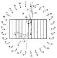
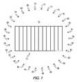
- FIG. 1is a schematic representation of a camera system constructed in accordance with the present invention
- FIG. 2is block diagram of the camera system of FIG. 1 showing additional components not shown in FIG. 1 ;
- FIG. 3is schematic representation of a camera that can be used in the system of FIG. 1 ;
- FIG. 4is a schematic representation of the camera system of FIG. 1 with various locations of objects of interest identified in the area of interest;
- FIG. 5is a schematic representation showing the various parameters that are measured or calculated when practicing the method of the present invention.
- FIGS. 6 a , 6 b , 6 c , 6 d and 6 eare frames of video images that illustrate the operation of the present invention.
- FIGS. 7 a , 7 b , 7 c , 7 d and 7 eare additional frames of video images that illustrate the operation of the present invention.
- FIG. 1is a schematic representation of a camera system 10 constructed in accordance with the present invention as it can be applied to a television broadcast of an American football game.
- the systemincludes a plurality of television cameras 12 , 14 , 16 , 18 , 20 , 22 , 24 , 26 , 28 , 30 , 32 , 34 , 36 , 38 , 40 , 42 , 44 , 46 , 48 , 50 , 52 , 54 , 56 , 58 , 60 , 62 , 64 , 66 , 68 and 70 positioned at different locations around the field of play 72 . While this example shows the use of thirty cameras, it should understood the invention is not limited to a particular number of cameras, and a greater or smaller number of cameras can be used within the scope of the invention.
- the camerasare located at spaced positions to provide video images of various objects of interest in the field of play from various spatial perspectives.
- FIG. 2is block diagram of the camera system of FIG. 1 showing additional components not shown in FIG. 1 . While only three cameras are shown in FIG. 2 , it will be understood that all of the cameras would be connected to the computer 84 in a manner similar to that shown in FIG. 2 .
- camera 12is shown as the master camera, and is coupled to a camera monitoring unit 74 that monitors the various parameters of the master camera that will be needed to coordinate the operation of the additional cameras 14 – 70 .
- the illustrated additional cameras 42 , 70are shown to be coupled to camera positioning and monitoring units 76 and 78 .
- the positioning and monitoring units 76 and 78receive control signals from the computer and control the position, focus and framing of the additional cameras in response to the control signals.
- the positioning and monitoring units 76 and 78also send signals to the computer that are representative of the operational status of the additional cameras.
- Master camera 12 and its associated monitoring unit 74are connected, either by wires 80 and 82 , or other suitable signal carrying media such as fiber optics or radio links, to a computer 84 , or other signal processing device for performing the system control, processing and storage functions.
- cameras 42 and 70 , and their associated positioning and monitoring units 76 and 78are connected, either by wires 86 , 88 , 90 and 92 , or other suitable signal carrying media such as fiber optics or radio links, to the computer 84 , so that operation of the cameras can be coordinated and video signals from the cameras can be recorded for future viewing and/or additional processing. Audio information collected by microphones at the camera locations can also be transmitted to the computer or another signal processing device by the same signal carrying media or by separate signal carrying media.
- the master camerais used to follow an object of interest in the event.
- the object of interestmight be a football or a particular player.
- information signals representative of the camera's movements, focus and framingare sent from the monitoring unit 74 to the computer 84 .
- the computerprocesses this information and provides control signals to the other cameras thereby directing the other cameras to follow the object of interest.
- a user interface 94is connected to the computer by wire 96 or another suitable control channel and used to direct the computer to provide a video output on line 98 for display 100 , and/or for further processing or transmission.
- FIG. 3is a schematic representation of one of the additional cameras 42 in a system constructed in accordance with the invention.
- FIG. 3shows the various parameters that must be known, such as the location of the camera shown as coordinates x, y and z, and parameters that can be controlled by the associated camera positioning and monitoring device, such as the pan direction 102 , the tilt direction 104 , and the rotational angle 106 .
- the pan, tilt and rotational angles of the individual camerascan be controlled by mounting the cameras on a robotic platform with the position of the platform being controlled automatically by various known arrangements of servo motors and mechanical couplings.
- the focus and zoom functionscan also be controlled remotely in accordance with known remote control technology, such as the Pro/Four Video Products 2000RP remote positioner.
- the location of the cameras with respect to each otherwould be determined using known techniques, such as by using a global positioning system or using triangulation to determine the location of the cameras with respect to predetermined landmarks in the scene, such as the corners of a football field.
- this informationcan be combined with information retrieved from the master camera, such as the distance from the master camera to an object of interest in the scene, to determine the movement, zoom and focus parameters for the additional cameras.
- This informationwill be supplied by the computer to the individual additional camera monitoring and control units to focus the additional cameras and to adjust the framing so that the object of interest is substantially the same size in each of the video images produced by the cameras.
- the master camerais manually controlled to focus on, and follow an object of interest.
- the object of interestshould be positioned within a portion of the camera's field of view, referred to as the “sweet spot”.
- the sweet spotis a portion of the camera's field of view that contains the object of interest.
- the sweet spotwould typically be near the center of a camera's field of view, but through the use of appropriate signal processing, other parts of the field of view could be used.
- the framing of an object at the sweet spotwould change in relation to the action being shot. For example, at the beginning of a football play, the shot might be wider to include most of the players, but as the focus is narrowed to one or two players, so would the framing of the master camera, and thus the slave cameras.
- the other camerasare automatically controlled to track the object of interest in a manner that permits subsequent viewing of the various images recorded by the cameras. That is, the automatically controlled additional cameras should focus on the object of interest and adjust the field of view so that the object of interest is substantially the same size in the images recorded by the various cameras.
- the inventionwill calculate the position of the object of interest, for example using an X-Y-Z coordinate system, where X and Y are perpendicular axes in a horizontal plane upon which the event being observed occurs. The Z direction is normal to the horizontal plane. Then all of the additional cameras will move in unison to track the object that is being tracked by the master camera. The zoom and focus of the additional cameras will be controlled so that the object of interest in each of the video images will be substantially the same size.
- video images produced by each camerawill be stored in the computer or a similar storage device. In the preferred embodiment, the images would be stored in a digital disc recorder, such as the Pinnacle Thunder or Tektronics Profile.
- FIG. 4assume that camera 12 is the master camera and is initially focused on an object of interest, such as a football player at location 108 .
- the computercan calculate the information needed to direct all of the additional cameras to focus on the object of interest and to adjust the frame size so that the object of interest appears to be substantially the same size in the video images produced by each of the cameras. This calculated information is then sent to the camera positioning units associated with each of the additional cameras, and the positioning units move the cameras to the correct position.
- the tilt angle of the master camerawill change to following the object. If the field of view is not changed at the master camera, the object of interest will appear smaller due the increased distance D 2 between the master camera and the object of interest.
- Camera 42which is located directly across the field from the master camera will be directed to change its tilt angle to follow the object of interest and will also have to increase its field of view (zoom out) so that the object of interest is substantially the same size in the image produced by camera 42 as it is in the image produced by the master camera. All of the other cameras will be directed to change their tilt angle, pan angle and zoom to image the object of interest from their respective spatial perspectives and to ensure that the object of interest is substantially the same size in their respective images as in the image produced by the master camera.
- the object of interestsubsequently moves along line 112 toward point 114 , the distance between the object of interest and camera 12 does not change, and assuming the that the framing size remains constant, the size of the object in the image produced by camera 12 will remain the same. However, since the distance between the object of interest and all of the other cameras has changed, all of the other cameras will have to adjust their zoom to keep the size of the object of interest in their images substantially the same as in the image produced by the master camera.
- a Cartesian coordinate systemwill be defined in which the field of play lies in an X,Y plane, with the Z direction being perpendicular to the plane.
- the master camerawill be manually controlled to focus on an object of interest, also referred to as a target.
- the target location on the fieldwill be derived from the master camera's pointing characteristics. Pan, tilt and zoom information from the master camera will be monitored, in the preferred embodiment using optical encoders, and fed back to the computer system.
- the computer systemwill then calculate the location of the target in X,Y space.
- a Z coordinatecan be assigned to the focal plane of field to provide the desired framing. For example, a Z coordinate of 4 feet above ground level would be appropriate for systems covering a football game.
- FIG. 5is a schematic representation of the relationships between a camera 12 and the target 116 .
- the master camera tilt angle (CT)can be used to calculate the line of sight distance, or focal distance (FD), and ground distance (GD) from the master camera, using the following formulas where Z is the height of the master camera above the X,Y plane.
- the camera pan informationcan be used to calculate the X and Y coordinates of the target. This is determined by finding the difference in the X position between the master camera location and the target location (DX) and the difference in the Y position between the master camera location and the target location (DY) using the following equations.
- CX,CYcamera's position in the world
- CX,CYcan be added to (DX,DY) to obtain the real world target coordinates of (TX,TY).
- Zoom information for the master cameracan be arrived at in two ways. Either by the computer telling the camera zoom what field of view is wanted or the computer getting the information from the camera zoom. In this example we will have the computer control zoom based on field of view (FV).
- the above stepsprovide all of the information needed from the master camera. This information can now be used to control the “slave” cameras.
- the robotic slave camera positioning systemmust be told where to point.
- the position of the slave camera in the world coordinatesis (CX,CY,Z).
- the CT, CP, FD, and FAare then sent to the slave camera robotic positioning system, which will cause the slave camera to track the target and match the framing of the master camera.
- This inventionis particularly suitable for providing improved video replay images.
- the video images of an event of interest from a plurality of the cameraswill be stored in a suitable storage medium, such as a digital data file or videotape system.
- a suitable storage mediumsuch as a digital data file or videotape system.
- one of the video imageswill be played until a particular video frame of the event of interest is depicted in the video. At that time, the video will be frozen to display the particular video frame.
- the displaywill then switch among frames in the video images that were produced by the other cameras.
- the frames of the video images that were produced by the other camerasmay be frames that correspond in time to the originally selected frame, or they may be other frames, such as those recorded at successive instants of time.
- the video imageshave been recorded from different spatial locations, that in the preferred embodiment encompass views surrounding the scene, this will effectively rotate the object being displayed.
- the cut between video sourcescan be done in a number of well-known ways, for example using a routing switcher such as the Grass Valley SMS 7000 or the Pesa Jaguar. Once a desired degree of rotation has been achieved, the video images from the camera positioned at the location viewing the desired angle of view can be played to continue full motion video.
- moving videocan be displayed by switching among the video images from the various cameras.
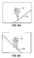
- FIGS. 6 a , 6 b , 6 c , 6 d and 6 eare simulated frames of video images that illustrate the operation of the present invention in a video replay mode.
- video images produced by camera 26 in FIG. 1are displayed on a monitor.
- the viewerwishes to see if player 118 has stepped on sideline 120 .
- a particular frame of the video produced by camera 26is selected and shown in FIG. 6 a .
- the viewercannot see if the player's left foot has hit sideline 120 .
- the corresponding frame produced by camera 34is shown in FIG. 6 b . In this frame it is apparent that the player's foot has touched the line 120 .
- FIGS. 6 c , 6 d and 6 eshows the corresponding frame from the video recorded by cameras 42 , 48 and 56 respectively. It should be apparent that by switching among corresponding frames of images recorded by the various cameras, the image of the player is effectively rotated on the display. Once a particular frame has been selected from the available frames, the full motion video can be resumed by running the video recorded from the camera that recorded the selected frame.
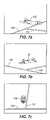
- FIGS. 7 a , 7 b , 7 c , 7 d and 7 eare simulated frames of video images that further illustrate the operation of the present invention.
- the viewerdesires to determine if the player 122 has crossed line 124 at the time that he crossed the sideline 126 .
- FIG. 7 ais a frame from the image recorded by camera 26 . From the spatial perspective of camera 26 , the viewer cannot tell if the player has crossed line 124 .
- FIG. 7 bis a frame recorded from camera 32 . Here again, the viewer cannot tell if the player has crossed line 124 .
- FIG. 7 cBy switching to the frame recorded by camera 36 , as shown in FIG. 7 c , the viewer can clearly see that the play is to the left of line 124 .
- FIGS. 7 d and 7 eshow corresponding frames recorded from cameras 48 and 58 , respectively.
- FIGS. 7 a , 7 b , 7 c , 7 d and 7 eagain illustrate how the invention uses a frozen image to effectively rotate the image on the display to provide information that might not be obtained from a fixed camera position.
- synthesized video imagescan be created by interpolating information in images taken by different cameras to produce views from spatial perspectives where cameras do not actually exist. Such synthesis can result in smoother transitions between images when the object of interest is rotated in the display.
- interpolation softwareavailable from Realviz Corporation could be used to perform the necessary image interpolation.
- This inventioncan be used as part of a live broadcast or as a replay device, giving a 360° view of an object or objects.
- camerascan be installed either at field level or at some point above the field level such as the mezzanine level of a stadium.
- the video images provided by the camera system of this inventionare similar to a virtual camera that can revolve around and object, as the object remains frozen.
- the image produced by the master cameracan be framed wide or tight, and the images produced by the additional cameras will automatically track the image produced by the master camera.
- This inventionfurther encompasses the detection, recording and playback of point specific audio.
- microphonesBy placing microphones at some or all of the camera locations such that the microphones receive sound from the direction of the field of view of the cameras, audio signals can be produced and fed to the computer for processing. Since the computer will have information concerning the position of the microphones, the audio signals produced by these microphones can be processed to produce an audio output signal representative of sound being produced at a particular location in the area occupied by the event being recorded. For example, since the distance from the camera to the object of interest can be calculated as shown above, if a microphone is mounted at the camera location, the time required for sound produced in the vicinity of the object of interest to reach the microphone location can be calculated.
- the microphonesSince the microphones are located at various distances with respect to the object of interest, the sound produced in the vicinity of the object of interest will reach the microphones at different times. By adding a time delay to the signals produced by the microphones to account for the differences in distance from the microphones to the vicinity of the object of interest, and subsequently combining the signals (for example by adding the signals), the sound produced in the vicinity of the object of interest can be recovered. This will produce an audio signal having a higher signal to noise ration than an audio signal produced by any of the individual microphones.
- the microphonescan be connected to the computer or another signal processing device using an arrangement similar to that shown in FIG. 2 .
- a director of a televised sporting eventcan produce replays of the events that permit an in-depth analysis of the action by combining information contained in video images taken from different spatial perspectives.
- the inventionalso provides the ability to change video framing during recording of an event.
- this inventionhas many practical applications, such as, golf swing analysis, and telecasts of basketball, gymnastics, track and field, boxing and entertainment events.
- Another exampleis the use of this invention in the movie industry.
- high definition video camerasin place of traditional film cameras to record a scene from a multiple of perspectives, a more complete record of the scene can be obtained, providing for more options in editing of the video for incorporation into a final video sequence. This could reduce the number of times that a scene would have to be recorded to obtain a desired video sequence.
Landscapes
- Engineering & Computer Science (AREA)
- Multimedia (AREA)
- Signal Processing (AREA)
- Studio Devices (AREA)
Abstract
Description
Z2+GD2=√{square root over (FD)}
GD*SIN(CP)=DX
GD*COS(CP)=DY
Then the camera's position in the world (CX,CY) can be added to (DX,DY) to obtain the real world target coordinates of (TX,TY).
90−ATAN 2(FV/2,FD)=FA
The above steps provide all of the information needed from the master camera. This information can now be used to control the “slave” cameras. First, the robotic slave camera positioning system must be told where to point. The position of the slave camera in the world coordinates is (CX,CY,Z).
TX−CX=DX
TY−CY=DY
√{square root over ((DX2+DY2))}=GD
The Camera Tilt (CT) angle can be found using the formula:
90−ATAN 2(GD,Z)=CT
The Camera Pan (CP) angle can be found using the formula:
90−ATAN 2(DX,DY)=CP
The Camera Focal Distance (FD) can be found using the formula:
√{square root over ((GD2+Z2))}=FD
The Focal Angle (FA) can be found using the formula:
90−ATAN 2(FV/2,GD)=FA
The CT, CP, FD, and FA are then sent to the slave camera robotic positioning system, which will cause the slave camera to track the target and match the framing of the master camera.
Claims (15)
Priority Applications (3)
| Application Number | Priority Date | Filing Date | Title |
|---|---|---|---|
| US09/626,568US7193645B1 (en) | 2000-07-27 | 2000-07-27 | Video system and method of operating a video system |
| PCT/US2001/019507WO2002011431A1 (en) | 2000-07-27 | 2001-06-18 | Video system and method of operating a video system |
| AU2001268546AAU2001268546A1 (en) | 2000-07-27 | 2001-06-18 | Video system and method of operating a video system |
Applications Claiming Priority (1)
| Application Number | Priority Date | Filing Date | Title |
|---|---|---|---|
| US09/626,568US7193645B1 (en) | 2000-07-27 | 2000-07-27 | Video system and method of operating a video system |
Publications (1)
| Publication Number | Publication Date |
|---|---|
| US7193645B1true US7193645B1 (en) | 2007-03-20 |
Family
ID=24510943
Family Applications (1)
| Application Number | Title | Priority Date | Filing Date |
|---|---|---|---|
| US09/626,568Expired - LifetimeUS7193645B1 (en) | 2000-07-27 | 2000-07-27 | Video system and method of operating a video system |
Country Status (3)
| Country | Link |
|---|---|
| US (1) | US7193645B1 (en) |
| AU (1) | AU2001268546A1 (en) |
| WO (1) | WO2002011431A1 (en) |
Cited By (56)
| Publication number | Priority date | Publication date | Assignee | Title |
|---|---|---|---|---|
| US20030210329A1 (en)* | 2001-11-08 | 2003-11-13 | Aagaard Kenneth Joseph | Video system and methods for operating a video system |
| US20040017389A1 (en)* | 2002-07-25 | 2004-01-29 | Hao Pan | Summarization of soccer video content |
| US20040109007A1 (en)* | 2002-12-09 | 2004-06-10 | Griss Martin L. | Directed guidance of viewing devices |
| US20050141039A1 (en)* | 2003-12-03 | 2005-06-30 | Canon Kabushiki Kaisha | Image capture apparatus and control method |
| US20060158526A1 (en)* | 2004-12-21 | 2006-07-20 | Kotaro Kashiwa | Image editing apparatus, image pickup apparatus, image editing method, and program |
| US20060228018A1 (en)* | 2005-04-12 | 2006-10-12 | Gil Abramovich | Reconfigurable machine vision system |
| US20070094602A1 (en)* | 2005-10-25 | 2007-04-26 | Sony Corporation | Display control device, and associated method of identifying content |
| US20070252674A1 (en)* | 2004-06-30 | 2007-11-01 | Joakim Nelson | Face Image Correction |
| US20080143842A1 (en)* | 2006-12-06 | 2008-06-19 | Sony United Kingdom Limited | Camera arrangement and method |
| US20090052805A1 (en)* | 2007-08-20 | 2009-02-26 | Michael James Knee | Video framing control |
| US20090118600A1 (en)* | 2007-11-02 | 2009-05-07 | Ortiz Joseph L | Method and apparatus for skin documentation and analysis |
| US20090231431A1 (en)* | 2008-03-17 | 2009-09-17 | International Business Machines Corporation | Displayed view modification in a vehicle-to-vehicle network |
| US20090231433A1 (en)* | 2008-03-17 | 2009-09-17 | International Business Machines Corporation | Scene selection in a vehicle-to-vehicle network |
| US20090231432A1 (en)* | 2008-03-17 | 2009-09-17 | International Business Machines Corporation | View selection in a vehicle-to-vehicle network |
| US20090231158A1 (en)* | 2008-03-17 | 2009-09-17 | International Business Machines Corporation | Guided video feed selection in a vehicle-to-vehicle network |
| US20090237510A1 (en)* | 2008-03-19 | 2009-09-24 | Microsoft Corporation | Visualizing camera feeds on a map |
| US20090251545A1 (en)* | 2008-04-06 | 2009-10-08 | Shekarri Nache D | Systems And Methods For Incident Recording |
| US20100085437A1 (en)* | 2008-10-07 | 2010-04-08 | The Boeing Company | Method and system involving controlling a video camera to track a movable target object |
| US20110085789A1 (en)* | 2009-10-13 | 2011-04-14 | Patrick Campbell | Frame Linked 2D/3D Camera System |
| US20110181716A1 (en)* | 2010-01-22 | 2011-07-28 | Crime Point, Incorporated | Video surveillance enhancement facilitating real-time proactive decision making |
| US8170413B2 (en) | 2010-03-31 | 2012-05-01 | James Cameron | Single seat-kill camera system |
| US20120169889A1 (en)* | 2006-10-26 | 2012-07-05 | Broadcom Corporation | Image creation with software controllable depth of field |
| US8427545B2 (en) | 2006-12-06 | 2013-04-23 | Sony Europe Limited | Method and an apparatus for generating image content |
| WO2013117801A1 (en)* | 2012-02-08 | 2013-08-15 | Nokia Corporation | Video viewing angle selection |
| US8527340B2 (en) | 2011-03-07 | 2013-09-03 | Kba2, Inc. | Systems and methods for analytic data gathering from image providers at an event or geographic location |
| US8655163B2 (en) | 2012-02-13 | 2014-02-18 | Cameron Pace Group Llc | Consolidated 2D/3D camera |
| US20140211982A1 (en)* | 2007-11-26 | 2014-07-31 | Proiam, Llc | Enrollment apparatus, system, and method |
| US20140240511A1 (en)* | 2013-02-25 | 2014-08-28 | Xerox Corporation | Automatically focusing a spectral imaging system onto an object in a scene |
| US20150189170A1 (en)* | 2012-10-05 | 2015-07-02 | Fuji Xerox Co., Ltd. | Information processing apparatus, information processing system and non-transitory computer readable medium |
| US20150201160A1 (en)* | 2014-01-10 | 2015-07-16 | Revolve Robotics, Inc. | Systems and methods for controlling robotic stands during videoconference operation |
| US9264474B2 (en) | 2013-05-07 | 2016-02-16 | KBA2 Inc. | System and method of portraying the shifting level of interest in an object or location |
| US20160227128A1 (en)* | 2015-01-29 | 2016-08-04 | Electronics And Telecommunications Research Institute | Multi-camera control apparatus and method to maintain location and size of object in continuous viewpoint switching service |
| US9485499B2 (en) | 2011-11-22 | 2016-11-01 | Israel Aerospace Industries Ltd. | System and method for processing multicamera array images |
| US20170048462A1 (en)* | 2015-08-14 | 2017-02-16 | Qualcomm Incorporated | Camera zoom based on sensor data |
| US9646444B2 (en) | 2000-06-27 | 2017-05-09 | Mesa Digital, Llc | Electronic wireless hand held multimedia device |
| US9674435B1 (en)* | 2016-07-06 | 2017-06-06 | Lawrence Maxwell Monari | Virtual reality platforms for capturing content for virtual reality displays |
| US10129569B2 (en) | 2000-10-26 | 2018-11-13 | Front Row Technologies, Llc | Wireless transmission of sports venue-based data including video to hand held devices |
| US10129579B2 (en) | 2015-10-15 | 2018-11-13 | At&T Mobility Ii Llc | Dynamic video image synthesis using multiple cameras and remote control |
| US20190108743A1 (en)* | 2017-10-08 | 2019-04-11 | Magik Eye Inc. | Calibrating a sensor system including multiple movable sensors |
| US10269384B2 (en) | 2008-04-06 | 2019-04-23 | Taser International, Inc. | Systems and methods for a recorder user interface |
| US10281979B2 (en)* | 2014-08-21 | 2019-05-07 | Canon Kabushiki Kaisha | Information processing system, information processing method, and storage medium |
| US10931883B2 (en) | 2018-03-20 | 2021-02-23 | Magik Eye Inc. | Adjusting camera exposure for three-dimensional depth sensing and two-dimensional imaging |
| US11002537B2 (en) | 2016-12-07 | 2021-05-11 | Magik Eye Inc. | Distance sensor including adjustable focus imaging sensor |
| US11019249B2 (en) | 2019-05-12 | 2021-05-25 | Magik Eye Inc. | Mapping three-dimensional depth map data onto two-dimensional images |
| US11062468B2 (en) | 2018-03-20 | 2021-07-13 | Magik Eye Inc. | Distance measurement using projection patterns of varying densities |
| US11113887B2 (en)* | 2018-01-08 | 2021-09-07 | Verizon Patent And Licensing Inc | Generating three-dimensional content from two-dimensional images |
| CN113573157A (en)* | 2021-07-23 | 2021-10-29 | 维沃移动通信(杭州)有限公司 | Video recording method, video recording device, electronic equipment and readable storage medium |
| US11199397B2 (en) | 2017-10-08 | 2021-12-14 | Magik Eye Inc. | Distance measurement using a longitudinal grid pattern |
| US11320537B2 (en) | 2019-12-01 | 2022-05-03 | Magik Eye Inc. | Enhancing triangulation-based three-dimensional distance measurements with time of flight information |
| US20220264075A1 (en)* | 2021-02-17 | 2022-08-18 | flexxCOACH VR | 360-degree virtual-reality system for dynamic events |
| US11474245B2 (en) | 2018-06-06 | 2022-10-18 | Magik Eye Inc. | Distance measurement using high density projection patterns |
| US11475584B2 (en) | 2018-08-07 | 2022-10-18 | Magik Eye Inc. | Baffles for three-dimensional sensors having spherical fields of view |
| US11474209B2 (en) | 2019-03-25 | 2022-10-18 | Magik Eye Inc. | Distance measurement using high density projection patterns |
| US11483503B2 (en) | 2019-01-20 | 2022-10-25 | Magik Eye Inc. | Three-dimensional sensor including bandpass filter having multiple passbands |
| US11580662B2 (en) | 2019-12-29 | 2023-02-14 | Magik Eye Inc. | Associating three-dimensional coordinates with two-dimensional feature points |
| US11688088B2 (en) | 2020-01-05 | 2023-06-27 | Magik Eye Inc. | Transferring the coordinate system of a three-dimensional camera to the incident point of a two-dimensional camera |
Families Citing this family (5)
| Publication number | Priority date | Publication date | Assignee | Title |
|---|---|---|---|---|
| US7106361B2 (en) | 2001-02-12 | 2006-09-12 | Carnegie Mellon University | System and method for manipulating the point of interest in a sequence of images |
| US7027083B2 (en) | 2001-02-12 | 2006-04-11 | Carnegie Mellon University | System and method for servoing on a moving fixation point within a dynamic scene |
| JP3787841B2 (en)* | 2002-06-05 | 2006-06-21 | ソニー株式会社 | Display device and display method |
| US20080291271A1 (en)* | 2007-05-21 | 2008-11-27 | Sony Ericsson Mobile Communications Ab | Remote viewfinding |
| CN105828206A (en)* | 2016-03-22 | 2016-08-03 | 乐视网信息技术(北京)股份有限公司 | Multi-video on-demand method and device |
Citations (39)
| Publication number | Priority date | Publication date | Assignee | Title |
|---|---|---|---|---|
| US3217098A (en)* | 1962-08-29 | 1965-11-09 | Robert A Oswald | Method of policing horse races |
| US3969588A (en) | 1974-11-29 | 1976-07-13 | Video And Audio Artistry Corporation | Audio pan generator |
| US4684990A (en) | 1985-04-12 | 1987-08-04 | Ampex Corporation | Method and apparatus for combining multiple video images in three dimensions |
| US4741038A (en) | 1986-09-26 | 1988-04-26 | American Telephone And Telegraph Company, At&T Bell Laboratories | Sound location arrangement |
| US4905081A (en) | 1986-11-06 | 1990-02-27 | British Broadcasting Corporation | Method and apparatus for transmitting and receiving 3D video pictures |
| US5101268A (en)* | 1989-12-05 | 1992-03-31 | Sony Corporation | Visual point position control apparatus |
| US5164827A (en)* | 1991-08-22 | 1992-11-17 | Sensormatic Electronics Corporation | Surveillance system with master camera control of slave cameras |
| US5363297A (en) | 1992-06-05 | 1994-11-08 | Larson Noble G | Automated camera-based tracking system for sports contests |
| US5434617A (en)* | 1993-01-29 | 1995-07-18 | Bell Communications Research, Inc. | Automatic tracking camera control system |
| US5448291A (en)* | 1993-06-30 | 1995-09-05 | Wickline; Dennis E. | Live video theater and method of presenting the same utilizing multiple cameras and monitors |
| US5495576A (en) | 1993-01-11 | 1996-02-27 | Ritchey; Kurtis J. | Panoramic image based virtual reality/telepresence audio-visual system and method |
| EP0714081A1 (en) | 1994-11-22 | 1996-05-29 | Sensormatic Electronics Corporation | Video surveillance system |
| US5590094A (en)* | 1991-11-25 | 1996-12-31 | Sony Corporation | System and methd for reproducing sound |
| US5598208A (en)* | 1994-09-26 | 1997-01-28 | Sony Corporation | Video viewing and recording system |
| US5617490A (en) | 1994-06-27 | 1997-04-01 | Sanyo Electric Co., Ltd. | Camera system with neural network compensator for measuring 3-D position |
| US5668595A (en) | 1992-03-23 | 1997-09-16 | Canon Kabushiki Kaisha | Multi-lens imaging apparatus having a mechanism for combining a plurality of images without displacement of registration |
| US5675377A (en) | 1995-06-30 | 1997-10-07 | Telefonaktiebolaget Lm Ericsson | True three-dimensional imaging and display system |
| US5684937A (en) | 1992-12-14 | 1997-11-04 | Oxaal; Ford | Method and apparatus for performing perspective transformation on visible stimuli |
| US5699444A (en) | 1995-03-31 | 1997-12-16 | Synthonics Incorporated | Methods and apparatus for using image data to determine camera location and orientation |
| US5729471A (en)* | 1995-03-31 | 1998-03-17 | The Regents Of The University Of California | Machine dynamic selection of one video camera/image of a scene from multiple video cameras/images of the scene in accordance with a particular perspective on the scene, an object in the scene, or an event in the scene |
| WO1998047291A2 (en) | 1997-04-16 | 1998-10-22 | Isight Ltd. | Video teleconferencing |
| US5831619A (en) | 1994-09-29 | 1998-11-03 | Fujitsu Limited | System for generating image of three-dimensional object seen from specified viewpoint |
| US5850352A (en) | 1995-03-31 | 1998-12-15 | The Regents Of The University Of California | Immersive video, including video hypermosaicing to generate from multiple video views of a scene a three-dimensional video mosaic from which diverse virtual video scene images are synthesized, including panoramic, scene interactive and stereoscopic images |
| US5892538A (en) | 1995-06-30 | 1999-04-06 | Ericsson Inc. | True three-dimensional imaging and display system |
| US5912700A (en)* | 1996-01-10 | 1999-06-15 | Fox Sports Productions, Inc. | System for enhancing the television presentation of an object at a sporting event |
| US5963203A (en) | 1997-07-03 | 1999-10-05 | Obvious Technology, Inc. | Interactive video icon with designated viewing position |
| US6002743A (en) | 1996-07-17 | 1999-12-14 | Telymonde; Timothy D. | Method and apparatus for image acquisition from a plurality of cameras |
| US6009188A (en) | 1996-02-16 | 1999-12-28 | Microsoft Corporation | Method and system for digital plenoptic imaging |
| US6014163A (en) | 1997-06-09 | 2000-01-11 | Evans & Sutherland Computer Corporation | Multi-camera virtual set system employing still store frame buffers for each camera |
| WO2000008856A1 (en) | 1998-08-07 | 2000-02-17 | Koninklijke Philips Electronics N.V. | Figure tracking in a multiple camera system |
| US6038368A (en) | 1996-02-05 | 2000-03-14 | Sony Corporation | System for acquiring, reviewing, and editing sports video segments |
| US6069961A (en) | 1996-11-27 | 2000-05-30 | Fujitsu Limited | Microphone system |
| US6133946A (en) | 1998-01-06 | 2000-10-17 | Sportvision, Inc. | System for determining the position of an object |
| US6160544A (en)* | 1997-05-12 | 2000-12-12 | Tokyo Broadcasting System, Inc. | Digital video distribution system |
| WO2001008417A1 (en) | 1999-07-26 | 2001-02-01 | Joseph Charles Bok | System, apparatus, and method for telemetry and monitoring of desired targets |
| US6275258B1 (en) | 1996-12-17 | 2001-08-14 | Nicholas Chim | Voice responsive image tracking system |
| US20020005902A1 (en)* | 2000-06-02 | 2002-01-17 | Yuen Henry C. | Automatic video recording system using wide-and narrow-field cameras |
| US20020118286A1 (en) | 2001-02-12 | 2002-08-29 | Takeo Kanade | System and method for servoing on a moving fixation point within a dynamic scene |
| US6507366B1 (en)* | 1998-04-16 | 2003-01-14 | Samsung Electronics Co., Ltd. | Method and apparatus for automatically tracking a moving object |
- 2000
- 2000-07-27USUS09/626,568patent/US7193645B1/ennot_activeExpired - Lifetime
- 2001
- 2001-06-18AUAU2001268546Apatent/AU2001268546A1/ennot_activeAbandoned
- 2001-06-18WOPCT/US2001/019507patent/WO2002011431A1/enactiveApplication Filing
Patent Citations (43)
| Publication number | Priority date | Publication date | Assignee | Title |
|---|---|---|---|---|
| US3217098A (en)* | 1962-08-29 | 1965-11-09 | Robert A Oswald | Method of policing horse races |
| US3969588A (en) | 1974-11-29 | 1976-07-13 | Video And Audio Artistry Corporation | Audio pan generator |
| US4684990A (en) | 1985-04-12 | 1987-08-04 | Ampex Corporation | Method and apparatus for combining multiple video images in three dimensions |
| US4741038A (en) | 1986-09-26 | 1988-04-26 | American Telephone And Telegraph Company, At&T Bell Laboratories | Sound location arrangement |
| US4905081A (en) | 1986-11-06 | 1990-02-27 | British Broadcasting Corporation | Method and apparatus for transmitting and receiving 3D video pictures |
| US5101268A (en)* | 1989-12-05 | 1992-03-31 | Sony Corporation | Visual point position control apparatus |
| US5164827A (en)* | 1991-08-22 | 1992-11-17 | Sensormatic Electronics Corporation | Surveillance system with master camera control of slave cameras |
| EP0529317A1 (en) | 1991-08-22 | 1993-03-03 | Sensormatic Electronics Corporation | Surveillance system with master camera control of slave cameras |
| US5590094A (en)* | 1991-11-25 | 1996-12-31 | Sony Corporation | System and methd for reproducing sound |
| US5668595A (en) | 1992-03-23 | 1997-09-16 | Canon Kabushiki Kaisha | Multi-lens imaging apparatus having a mechanism for combining a plurality of images without displacement of registration |
| US5363297A (en) | 1992-06-05 | 1994-11-08 | Larson Noble G | Automated camera-based tracking system for sports contests |
| US5684937A (en) | 1992-12-14 | 1997-11-04 | Oxaal; Ford | Method and apparatus for performing perspective transformation on visible stimuli |
| US5495576A (en) | 1993-01-11 | 1996-02-27 | Ritchey; Kurtis J. | Panoramic image based virtual reality/telepresence audio-visual system and method |
| US5434617A (en)* | 1993-01-29 | 1995-07-18 | Bell Communications Research, Inc. | Automatic tracking camera control system |
| US5448291A (en)* | 1993-06-30 | 1995-09-05 | Wickline; Dennis E. | Live video theater and method of presenting the same utilizing multiple cameras and monitors |
| US5617490A (en) | 1994-06-27 | 1997-04-01 | Sanyo Electric Co., Ltd. | Camera system with neural network compensator for measuring 3-D position |
| US5598208A (en)* | 1994-09-26 | 1997-01-28 | Sony Corporation | Video viewing and recording system |
| US5831619A (en) | 1994-09-29 | 1998-11-03 | Fujitsu Limited | System for generating image of three-dimensional object seen from specified viewpoint |
| EP0714081A1 (en) | 1994-11-22 | 1996-05-29 | Sensormatic Electronics Corporation | Video surveillance system |
| US5729471A (en)* | 1995-03-31 | 1998-03-17 | The Regents Of The University Of California | Machine dynamic selection of one video camera/image of a scene from multiple video cameras/images of the scene in accordance with a particular perspective on the scene, an object in the scene, or an event in the scene |
| US5745126A (en) | 1995-03-31 | 1998-04-28 | The Regents Of The University Of California | Machine synthesis of a virtual video camera/image of a scene from multiple video cameras/images of the scene in accordance with a particular perspective on the scene, an object in the scene, or an event in the scene |
| US5699444A (en) | 1995-03-31 | 1997-12-16 | Synthonics Incorporated | Methods and apparatus for using image data to determine camera location and orientation |
| US5850352A (en) | 1995-03-31 | 1998-12-15 | The Regents Of The University Of California | Immersive video, including video hypermosaicing to generate from multiple video views of a scene a three-dimensional video mosaic from which diverse virtual video scene images are synthesized, including panoramic, scene interactive and stereoscopic images |
| US5892538A (en) | 1995-06-30 | 1999-04-06 | Ericsson Inc. | True three-dimensional imaging and display system |
| US5675377A (en) | 1995-06-30 | 1997-10-07 | Telefonaktiebolaget Lm Ericsson | True three-dimensional imaging and display system |
| US6154250A (en)* | 1996-01-10 | 2000-11-28 | Fox Sports Productions, Inc. | System for enhancing the television presentation of an object at a sporting event |
| US5912700A (en)* | 1996-01-10 | 1999-06-15 | Fox Sports Productions, Inc. | System for enhancing the television presentation of an object at a sporting event |
| US6038368A (en) | 1996-02-05 | 2000-03-14 | Sony Corporation | System for acquiring, reviewing, and editing sports video segments |
| US6009188A (en) | 1996-02-16 | 1999-12-28 | Microsoft Corporation | Method and system for digital plenoptic imaging |
| US6002743A (en) | 1996-07-17 | 1999-12-14 | Telymonde; Timothy D. | Method and apparatus for image acquisition from a plurality of cameras |
| US6069961A (en) | 1996-11-27 | 2000-05-30 | Fujitsu Limited | Microphone system |
| US6275258B1 (en) | 1996-12-17 | 2001-08-14 | Nicholas Chim | Voice responsive image tracking system |
| WO1998047291A2 (en) | 1997-04-16 | 1998-10-22 | Isight Ltd. | Video teleconferencing |
| US6160544A (en)* | 1997-05-12 | 2000-12-12 | Tokyo Broadcasting System, Inc. | Digital video distribution system |
| US6014163A (en) | 1997-06-09 | 2000-01-11 | Evans & Sutherland Computer Corporation | Multi-camera virtual set system employing still store frame buffers for each camera |
| US5963203A (en) | 1997-07-03 | 1999-10-05 | Obvious Technology, Inc. | Interactive video icon with designated viewing position |
| US6133946A (en) | 1998-01-06 | 2000-10-17 | Sportvision, Inc. | System for determining the position of an object |
| US6507366B1 (en)* | 1998-04-16 | 2003-01-14 | Samsung Electronics Co., Ltd. | Method and apparatus for automatically tracking a moving object |
| WO2000008856A1 (en) | 1998-08-07 | 2000-02-17 | Koninklijke Philips Electronics N.V. | Figure tracking in a multiple camera system |
| US6359647B1 (en)* | 1998-08-07 | 2002-03-19 | Philips Electronics North America Corporation | Automated camera handoff system for figure tracking in a multiple camera system |
| WO2001008417A1 (en) | 1999-07-26 | 2001-02-01 | Joseph Charles Bok | System, apparatus, and method for telemetry and monitoring of desired targets |
| US20020005902A1 (en)* | 2000-06-02 | 2002-01-17 | Yuen Henry C. | Automatic video recording system using wide-and narrow-field cameras |
| US20020118286A1 (en) | 2001-02-12 | 2002-08-29 | Takeo Kanade | System and method for servoing on a moving fixation point within a dynamic scene |
Non-Patent Citations (4)
| Title |
|---|
| Glossary: Optical: Focal Length, 1998-2006, URL address: http://www.dpreview.com/learn/?/key=focal+length.* |
| Martzke, "CBS gives instant replay at 21<SUP>st </SUP>century look," USA Today, Jan. 23, 2001, p. 3C. |
| Nikon Coolpix 990 User Guide, Apr. 15, 2000; URL address: http://www.cs.mtu.edu/~shene/DigiCam/User-Guide/990/ON-CAMERA-LENS/optical-zoom.html.* |
| Rander, "A Multi-Camera Method for 3D Digitization of Dynamic, Real-World Events," Submitted in partial fulfillment of the requirements for the degree of Doctor of Philosophy in Electrical and Computer Engineering, May 1998. |
Cited By (99)
| Publication number | Priority date | Publication date | Assignee | Title |
|---|---|---|---|---|
| US9646444B2 (en) | 2000-06-27 | 2017-05-09 | Mesa Digital, Llc | Electronic wireless hand held multimedia device |
| US10129569B2 (en) | 2000-10-26 | 2018-11-13 | Front Row Technologies, Llc | Wireless transmission of sports venue-based data including video to hand held devices |
| US20110211096A1 (en)* | 2001-11-08 | 2011-09-01 | Kenneth Joseph Aagaard | Video system and methods for operating a video system |
| US8675073B2 (en) | 2001-11-08 | 2014-03-18 | Kenneth Joseph Aagaard | Video system and methods for operating a video system |
| US20030210329A1 (en)* | 2001-11-08 | 2003-11-13 | Aagaard Kenneth Joseph | Video system and methods for operating a video system |
| US20040017389A1 (en)* | 2002-07-25 | 2004-01-29 | Hao Pan | Summarization of soccer video content |
| US7657836B2 (en)* | 2002-07-25 | 2010-02-02 | Sharp Laboratories Of America, Inc. | Summarization of soccer video content |
| US20040109007A1 (en)* | 2002-12-09 | 2004-06-10 | Griss Martin L. | Directed guidance of viewing devices |
| US7589852B2 (en)* | 2003-12-03 | 2009-09-15 | Canon Kabushiki Kaisha | Image capture apparatus and control method |
| US20050141039A1 (en)* | 2003-12-03 | 2005-06-30 | Canon Kabushiki Kaisha | Image capture apparatus and control method |
| US20070252674A1 (en)* | 2004-06-30 | 2007-11-01 | Joakim Nelson | Face Image Correction |
| US8208010B2 (en)* | 2004-06-30 | 2012-06-26 | Sony Ericsson Mobile Communications Ab | Face image correction using multiple camera angles |
| US20060158526A1 (en)* | 2004-12-21 | 2006-07-20 | Kotaro Kashiwa | Image editing apparatus, image pickup apparatus, image editing method, and program |
| US10068158B2 (en) | 2004-12-21 | 2018-09-04 | Sony Corporation | Image processing systems and methods for automatically generating image album data from multiple cameras |
| US8599275B2 (en)* | 2004-12-21 | 2013-12-03 | Sony Corporation | Image editing apparatus, image pickup apparatus, image editing method, and program |
| US20060228018A1 (en)* | 2005-04-12 | 2006-10-12 | Gil Abramovich | Reconfigurable machine vision system |
| US20070094602A1 (en)* | 2005-10-25 | 2007-04-26 | Sony Corporation | Display control device, and associated method of identifying content |
| US8009232B2 (en)* | 2005-10-25 | 2011-08-30 | Sony Corporation | Display control device, and associated method of identifying content |
| US8879870B2 (en)* | 2006-10-26 | 2014-11-04 | Broadcom Corporation | Image creation with software controllable depth of field |
| US20120169889A1 (en)* | 2006-10-26 | 2012-07-05 | Broadcom Corporation | Image creation with software controllable depth of field |
| US8848066B2 (en) | 2006-12-06 | 2014-09-30 | Sony Europe Limited | Method and an apparatus for generating image content |
| US20080143842A1 (en)* | 2006-12-06 | 2008-06-19 | Sony United Kingdom Limited | Camera arrangement and method |
| US8013899B2 (en)* | 2006-12-06 | 2011-09-06 | Sony United Kingdom Limited | Camera arrangement and method |
| US8427545B2 (en) | 2006-12-06 | 2013-04-23 | Sony Europe Limited | Method and an apparatus for generating image content |
| US8587679B2 (en) | 2007-08-20 | 2013-11-19 | Snell Limited | Video framing control in which operator framing of narrow view image controls automatic framing of wide view image |
| US20090052805A1 (en)* | 2007-08-20 | 2009-02-26 | Michael James Knee | Video framing control |
| US8102432B2 (en)* | 2007-08-20 | 2012-01-24 | Snell Limited | Video framing control in which operator framing of narrow view image controls automatic framing of wide view image |
| US20090118600A1 (en)* | 2007-11-02 | 2009-05-07 | Ortiz Joseph L | Method and apparatus for skin documentation and analysis |
| US20140211982A1 (en)* | 2007-11-26 | 2014-07-31 | Proiam, Llc | Enrollment apparatus, system, and method |
| US9043483B2 (en) | 2008-03-17 | 2015-05-26 | International Business Machines Corporation | View selection in a vehicle-to-vehicle network |
| US10671259B2 (en) | 2008-03-17 | 2020-06-02 | International Business Machines Corporation | Guided video feed selection in a vehicle-to-vehicle network |
| US20090231431A1 (en)* | 2008-03-17 | 2009-09-17 | International Business Machines Corporation | Displayed view modification in a vehicle-to-vehicle network |
| US20090231432A1 (en)* | 2008-03-17 | 2009-09-17 | International Business Machines Corporation | View selection in a vehicle-to-vehicle network |
| US8345098B2 (en) | 2008-03-17 | 2013-01-01 | International Business Machines Corporation | Displayed view modification in a vehicle-to-vehicle network |
| US8400507B2 (en)* | 2008-03-17 | 2013-03-19 | International Business Machines Corporation | Scene selection in a vehicle-to-vehicle network |
| US20090231433A1 (en)* | 2008-03-17 | 2009-09-17 | International Business Machines Corporation | Scene selection in a vehicle-to-vehicle network |
| US9123241B2 (en) | 2008-03-17 | 2015-09-01 | International Business Machines Corporation | Guided video feed selection in a vehicle-to-vehicle network |
| US20090231158A1 (en)* | 2008-03-17 | 2009-09-17 | International Business Machines Corporation | Guided video feed selection in a vehicle-to-vehicle network |
| US8237791B2 (en)* | 2008-03-19 | 2012-08-07 | Microsoft Corporation | Visualizing camera feeds on a map |
| US20090237510A1 (en)* | 2008-03-19 | 2009-09-24 | Microsoft Corporation | Visualizing camera feeds on a map |
| US10354689B2 (en) | 2008-04-06 | 2019-07-16 | Taser International, Inc. | Systems and methods for event recorder logging |
| US11386929B2 (en) | 2008-04-06 | 2022-07-12 | Axon Enterprise, Inc. | Systems and methods for incident recording |
| US12431167B2 (en) | 2008-04-06 | 2025-09-30 | Axon Enterprise, Inc. | Incident recording systems and methods |
| US20090251311A1 (en)* | 2008-04-06 | 2009-10-08 | Smith Patrick W | Systems And Methods For Cooperative Stimulus Control |
| US11854578B2 (en) | 2008-04-06 | 2023-12-26 | Axon Enterprise, Inc. | Shift hub dock for incident recording systems and methods |
| US10269384B2 (en) | 2008-04-06 | 2019-04-23 | Taser International, Inc. | Systems and methods for a recorder user interface |
| US20090251545A1 (en)* | 2008-04-06 | 2009-10-08 | Shekarri Nache D | Systems And Methods For Incident Recording |
| US10446183B2 (en) | 2008-04-06 | 2019-10-15 | Taser International, Inc. | Systems and methods for a recorder user interface |
| US10872636B2 (en) | 2008-04-06 | 2020-12-22 | Axon Enterprise, Inc. | Systems and methods for incident recording |
| US8199194B2 (en)* | 2008-10-07 | 2012-06-12 | The Boeing Company | Method and system involving controlling a video camera to track a movable target object |
| US20100085437A1 (en)* | 2008-10-07 | 2010-04-08 | The Boeing Company | Method and system involving controlling a video camera to track a movable target object |
| US8090251B2 (en) | 2009-10-13 | 2012-01-03 | James Cameron | Frame linked 2D/3D camera system |
| US20110085789A1 (en)* | 2009-10-13 | 2011-04-14 | Patrick Campbell | Frame Linked 2D/3D Camera System |
| US20110181716A1 (en)* | 2010-01-22 | 2011-07-28 | Crime Point, Incorporated | Video surveillance enhancement facilitating real-time proactive decision making |
| US8306415B2 (en) | 2010-03-31 | 2012-11-06 | Vincent Pace | Single seat-kill camera system |
| US8170413B2 (en) | 2010-03-31 | 2012-05-01 | James Cameron | Single seat-kill camera system |
| US9020832B2 (en) | 2011-03-07 | 2015-04-28 | KBA2 Inc. | Systems and methods for analytic data gathering from image providers at an event or geographic location |
| US8527340B2 (en) | 2011-03-07 | 2013-09-03 | Kba2, Inc. | Systems and methods for analytic data gathering from image providers at an event or geographic location |
| US9485499B2 (en) | 2011-11-22 | 2016-11-01 | Israel Aerospace Industries Ltd. | System and method for processing multicamera array images |
| US8805158B2 (en) | 2012-02-08 | 2014-08-12 | Nokia Corporation | Video viewing angle selection |
| WO2013117801A1 (en)* | 2012-02-08 | 2013-08-15 | Nokia Corporation | Video viewing angle selection |
| US8655163B2 (en) | 2012-02-13 | 2014-02-18 | Cameron Pace Group Llc | Consolidated 2D/3D camera |
| US20150189170A1 (en)* | 2012-10-05 | 2015-07-02 | Fuji Xerox Co., Ltd. | Information processing apparatus, information processing system and non-transitory computer readable medium |
| US9942471B2 (en)* | 2012-10-05 | 2018-04-10 | Fuji Xerox Co., Ltd. | Information processing apparatus, information processing system and non-transitory computer readable medium |
| US20140240511A1 (en)* | 2013-02-25 | 2014-08-28 | Xerox Corporation | Automatically focusing a spectral imaging system onto an object in a scene |
| US9264474B2 (en) | 2013-05-07 | 2016-02-16 | KBA2 Inc. | System and method of portraying the shifting level of interest in an object or location |
| US9615053B2 (en)* | 2014-01-10 | 2017-04-04 | Revolve Robotics, Inc. | Systems and methods for controlling robotic stands during videoconference operation |
| US20150201160A1 (en)* | 2014-01-10 | 2015-07-16 | Revolve Robotics, Inc. | Systems and methods for controlling robotic stands during videoconference operation |
| US10281979B2 (en)* | 2014-08-21 | 2019-05-07 | Canon Kabushiki Kaisha | Information processing system, information processing method, and storage medium |
| US9786064B2 (en)* | 2015-01-29 | 2017-10-10 | Electronics And Telecommunications Research Institute | Multi-camera control apparatus and method to maintain location and size of object in continuous viewpoint switching service |
| US20160227128A1 (en)* | 2015-01-29 | 2016-08-04 | Electronics And Telecommunications Research Institute | Multi-camera control apparatus and method to maintain location and size of object in continuous viewpoint switching service |
| US20170048462A1 (en)* | 2015-08-14 | 2017-02-16 | Qualcomm Incorporated | Camera zoom based on sensor data |
| US10397484B2 (en)* | 2015-08-14 | 2019-08-27 | Qualcomm Incorporated | Camera zoom based on sensor data |
| US10129579B2 (en) | 2015-10-15 | 2018-11-13 | At&T Mobility Ii Llc | Dynamic video image synthesis using multiple cameras and remote control |
| US11025978B2 (en) | 2015-10-15 | 2021-06-01 | At&T Mobility Ii Llc | Dynamic video image synthesis using multiple cameras and remote control |
| US10631032B2 (en) | 2015-10-15 | 2020-04-21 | At&T Mobility Ii Llc | Dynamic video image synthesis using multiple cameras and remote control |
| US9674435B1 (en)* | 2016-07-06 | 2017-06-06 | Lawrence Maxwell Monari | Virtual reality platforms for capturing content for virtual reality displays |
| US11002537B2 (en) | 2016-12-07 | 2021-05-11 | Magik Eye Inc. | Distance sensor including adjustable focus imaging sensor |
| US11199397B2 (en) | 2017-10-08 | 2021-12-14 | Magik Eye Inc. | Distance measurement using a longitudinal grid pattern |
| US10885761B2 (en)* | 2017-10-08 | 2021-01-05 | Magik Eye Inc. | Calibrating a sensor system including multiple movable sensors |
| US20190108743A1 (en)* | 2017-10-08 | 2019-04-11 | Magik Eye Inc. | Calibrating a sensor system including multiple movable sensors |
| US11113887B2 (en)* | 2018-01-08 | 2021-09-07 | Verizon Patent And Licensing Inc | Generating three-dimensional content from two-dimensional images |
| US11062468B2 (en) | 2018-03-20 | 2021-07-13 | Magik Eye Inc. | Distance measurement using projection patterns of varying densities |
| US11381753B2 (en) | 2018-03-20 | 2022-07-05 | Magik Eye Inc. | Adjusting camera exposure for three-dimensional depth sensing and two-dimensional imaging |
| US10931883B2 (en) | 2018-03-20 | 2021-02-23 | Magik Eye Inc. | Adjusting camera exposure for three-dimensional depth sensing and two-dimensional imaging |
| US11474245B2 (en) | 2018-06-06 | 2022-10-18 | Magik Eye Inc. | Distance measurement using high density projection patterns |
| US11475584B2 (en) | 2018-08-07 | 2022-10-18 | Magik Eye Inc. | Baffles for three-dimensional sensors having spherical fields of view |
| US11483503B2 (en) | 2019-01-20 | 2022-10-25 | Magik Eye Inc. | Three-dimensional sensor including bandpass filter having multiple passbands |
| US11474209B2 (en) | 2019-03-25 | 2022-10-18 | Magik Eye Inc. | Distance measurement using high density projection patterns |
| US11019249B2 (en) | 2019-05-12 | 2021-05-25 | Magik Eye Inc. | Mapping three-dimensional depth map data onto two-dimensional images |
| US11320537B2 (en) | 2019-12-01 | 2022-05-03 | Magik Eye Inc. | Enhancing triangulation-based three-dimensional distance measurements with time of flight information |
| US11580662B2 (en) | 2019-12-29 | 2023-02-14 | Magik Eye Inc. | Associating three-dimensional coordinates with two-dimensional feature points |
| US11688088B2 (en) | 2020-01-05 | 2023-06-27 | Magik Eye Inc. | Transferring the coordinate system of a three-dimensional camera to the incident point of a two-dimensional camera |
| US20220264075A1 (en)* | 2021-02-17 | 2022-08-18 | flexxCOACH VR | 360-degree virtual-reality system for dynamic events |
| US20230217004A1 (en)* | 2021-02-17 | 2023-07-06 | flexxCOACH VR | 360-degree virtual-reality system for dynamic events |
| US11622100B2 (en)* | 2021-02-17 | 2023-04-04 | flexxCOACH VR | 360-degree virtual-reality system for dynamic events |
| US12041220B2 (en)* | 2021-02-17 | 2024-07-16 | flexxCOACH VR | 360-degree virtual-reality system for dynamic events |
| CN113573157B (en)* | 2021-07-23 | 2023-09-12 | 维沃移动通信(杭州)有限公司 | Video recording method, video recording device, electronic apparatus, and readable storage medium |
| CN113573157A (en)* | 2021-07-23 | 2021-10-29 | 维沃移动通信(杭州)有限公司 | Video recording method, video recording device, electronic equipment and readable storage medium |
Also Published As
| Publication number | Publication date |
|---|---|
| WO2002011431A1 (en) | 2002-02-07 |
| AU2001268546A1 (en) | 2002-02-13 |
Similar Documents
| Publication | Publication Date | Title |
|---|---|---|
| US7193645B1 (en) | Video system and method of operating a video system | |
| US6741250B1 (en) | Method and system for generation of multiple viewpoints into a scene viewed by motionless cameras and for presentation of a view path | |
| US9596457B2 (en) | Video system and methods for operating a video system | |
| US10582182B2 (en) | Video capture and rendering system control using multiple virtual cameras | |
| JP7123523B2 (en) | Method and system for automatically producing television programs | |
| US9751015B2 (en) | Augmented reality videogame broadcast programming | |
| US7613999B2 (en) | Navigable telepresence method and systems utilizing an array of cameras | |
| AU2010286316B2 (en) | A method and apparatus for relative control of multiple cameras | |
| US5953056A (en) | System and method for enhancing display of a sporting event | |
| CN103051830B (en) | A kind of system and method to clapped target multi-angle live event | |
| EP0669758B1 (en) | Time-varying image processor and display device | |
| US8885022B2 (en) | Virtual camera control using motion control systems for augmented reality | |
| US20150009298A1 (en) | Virtual Camera Control Using Motion Control Systems for Augmented Three Dimensional Reality | |
| WO2001028309A2 (en) | Method and system for comparing multiple images utilizing a navigable array of cameras | |
| WO2018094443A1 (en) | Multiple video camera system | |
| US9736462B2 (en) | Three-dimensional video production system | |
| JPH06105231A (en) | Image synthesizer | |
| WO2003041411A1 (en) | Video system and methods for operating a video system | |
| EP4429234A1 (en) | Image capturing system and method | |
| JPH09507620A (en) | Observing a captured object from a selected viewpoint | |
| WO2002087218A2 (en) | Navigable camera array and viewer therefore | |
| JPH0926966A (en) | Video playback method and video playback device |
Legal Events
| Date | Code | Title | Description |
|---|---|---|---|
| AS | Assignment | Owner name:CBS BROADCASTING INC., NEW YORK Free format text:ASSIGNMENT OF ASSIGNORS INTEREST;ASSIGNORS:AAGAARD, KENNETH JOHN;BARBATSOULIS, LARRY;MCMANUS, SEAN JOSEPH;AND OTHERS;REEL/FRAME:010966/0302;SIGNING DATES FROM 20000725 TO 20000726 | |
| AS | Assignment | Owner name:REVOLUTION COMPANY, LLC, NEW YORK Free format text:ASSIGNMENT OF ASSIGNORS INTEREST;ASSIGNOR:CBS BROADCASTING INC.;REEL/FRAME:011804/0192 Effective date:20010417 | |
| AS | Assignment | Owner name:PVI VIRTUAL MEDIA SERVICES, LLC, NEW YORK Free format text:ASSIGNMENT OF ASSIGNORS INTEREST;ASSIGNOR:REVOLUTION COMPANY, LLC;REEL/FRAME:016239/0140 Effective date:20050708 | |
| STCF | Information on status: patent grant | Free format text:PATENTED CASE | |
| FPAY | Fee payment | Year of fee payment:4 | |
| AS | Assignment | Owner name:ESPN TECHNOLOGY SERVICES, INC., CONNECTICUT Free format text:ASSIGNMENT OF ASSIGNORS INTEREST;ASSIGNOR:PVI VIRTUAL MEDIA SERVICES, LLC;REEL/FRAME:026054/0053 Effective date:20101210 | |
| AS | Assignment | Owner name:DISNEY ENTERPRISES, INC., CALIFORNIA Free format text:ASSIGNMENT OF ASSIGNORS INTEREST;ASSIGNOR:ESPN TECHNOLOGY SERVICES, INC.;REEL/FRAME:026061/0159 Effective date:20110330 | |
| FPAY | Fee payment | Year of fee payment:8 | |
| MAFP | Maintenance fee payment | Free format text:PAYMENT OF MAINTENANCE FEE, 12TH YEAR, LARGE ENTITY (ORIGINAL EVENT CODE: M1553); ENTITY STATUS OF PATENT OWNER: LARGE ENTITY Year of fee payment:12 |