US7192888B1 - Low selectivity deposition methods - Google Patents
Low selectivity deposition methodsDownload PDFInfo
- Publication number
- US7192888B1 US7192888B1US09/643,004US64300400AUS7192888B1US 7192888 B1US7192888 B1US 7192888B1US 64300400 AUS64300400 AUS 64300400AUS 7192888 B1US7192888 B1US 7192888B1
- Authority
- US
- United States
- Prior art keywords
- nucleation layer
- deposition method
- layer
- deposition
- forming
- Prior art date
- Legal status (The legal status is an assumption and is not a legal conclusion. Google has not performed a legal analysis and makes no representation as to the accuracy of the status listed.)
- Expired - Lifetime, expires
Links
Images

Classifications
- H—ELECTRICITY
- H01—ELECTRIC ELEMENTS
- H01L—SEMICONDUCTOR DEVICES NOT COVERED BY CLASS H10
- H01L21/00—Processes or apparatus adapted for the manufacture or treatment of semiconductor or solid state devices or of parts thereof
- H01L21/02—Manufacture or treatment of semiconductor devices or of parts thereof
- H01L21/02104—Forming layers
- H01L21/02107—Forming insulating materials on a substrate
- H01L21/02225—Forming insulating materials on a substrate characterised by the process for the formation of the insulating layer
- H01L21/0226—Forming insulating materials on a substrate characterised by the process for the formation of the insulating layer formation by a deposition process
- H01L21/02263—Forming insulating materials on a substrate characterised by the process for the formation of the insulating layer formation by a deposition process deposition from the gas or vapour phase
- H01L21/02271—Forming insulating materials on a substrate characterised by the process for the formation of the insulating layer formation by a deposition process deposition from the gas or vapour phase deposition by decomposition or reaction of gaseous or vapour phase compounds, i.e. chemical vapour deposition
- C—CHEMISTRY; METALLURGY
- C23—COATING METALLIC MATERIAL; COATING MATERIAL WITH METALLIC MATERIAL; CHEMICAL SURFACE TREATMENT; DIFFUSION TREATMENT OF METALLIC MATERIAL; COATING BY VACUUM EVAPORATION, BY SPUTTERING, BY ION IMPLANTATION OR BY CHEMICAL VAPOUR DEPOSITION, IN GENERAL; INHIBITING CORROSION OF METALLIC MATERIAL OR INCRUSTATION IN GENERAL
- C23C—COATING METALLIC MATERIAL; COATING MATERIAL WITH METALLIC MATERIAL; SURFACE TREATMENT OF METALLIC MATERIAL BY DIFFUSION INTO THE SURFACE, BY CHEMICAL CONVERSION OR SUBSTITUTION; COATING BY VACUUM EVAPORATION, BY SPUTTERING, BY ION IMPLANTATION OR BY CHEMICAL VAPOUR DEPOSITION, IN GENERAL
- C23C16/00—Chemical coating by decomposition of gaseous compounds, without leaving reaction products of surface material in the coating, i.e. chemical vapour deposition [CVD] processes
- C23C16/02—Pretreatment of the material to be coated
- C23C16/0272—Deposition of sub-layers, e.g. to promote the adhesion of the main coating
- C—CHEMISTRY; METALLURGY
- C23—COATING METALLIC MATERIAL; COATING MATERIAL WITH METALLIC MATERIAL; CHEMICAL SURFACE TREATMENT; DIFFUSION TREATMENT OF METALLIC MATERIAL; COATING BY VACUUM EVAPORATION, BY SPUTTERING, BY ION IMPLANTATION OR BY CHEMICAL VAPOUR DEPOSITION, IN GENERAL; INHIBITING CORROSION OF METALLIC MATERIAL OR INCRUSTATION IN GENERAL
- C23C—COATING METALLIC MATERIAL; COATING MATERIAL WITH METALLIC MATERIAL; SURFACE TREATMENT OF METALLIC MATERIAL BY DIFFUSION INTO THE SURFACE, BY CHEMICAL CONVERSION OR SUBSTITUTION; COATING BY VACUUM EVAPORATION, BY SPUTTERING, BY ION IMPLANTATION OR BY CHEMICAL VAPOUR DEPOSITION, IN GENERAL
- C23C16/00—Chemical coating by decomposition of gaseous compounds, without leaving reaction products of surface material in the coating, i.e. chemical vapour deposition [CVD] processes
- C23C16/44—Chemical coating by decomposition of gaseous compounds, without leaving reaction products of surface material in the coating, i.e. chemical vapour deposition [CVD] processes characterised by the method of coating
- C23C16/455—Chemical coating by decomposition of gaseous compounds, without leaving reaction products of surface material in the coating, i.e. chemical vapour deposition [CVD] processes characterised by the method of coating characterised by the method used for introducing gases into reaction chamber or for modifying gas flows in reaction chamber
- C23C16/45523—Pulsed gas flow or change of composition over time
- C23C16/45525—Atomic layer deposition [ALD]
- H—ELECTRICITY
- H01—ELECTRIC ELEMENTS
- H01L—SEMICONDUCTOR DEVICES NOT COVERED BY CLASS H10
- H01L21/00—Processes or apparatus adapted for the manufacture or treatment of semiconductor or solid state devices or of parts thereof
- H01L21/02—Manufacture or treatment of semiconductor devices or of parts thereof
- H01L21/02104—Forming layers
- H01L21/02107—Forming insulating materials on a substrate
- H01L21/02109—Forming insulating materials on a substrate characterised by the type of layer, e.g. type of material, porous/non-porous, pre-cursors, mixtures or laminates
- H01L21/02112—Forming insulating materials on a substrate characterised by the type of layer, e.g. type of material, porous/non-porous, pre-cursors, mixtures or laminates characterised by the material of the layer
- H01L21/02172—Forming insulating materials on a substrate characterised by the type of layer, e.g. type of material, porous/non-porous, pre-cursors, mixtures or laminates characterised by the material of the layer the material containing at least one metal element, e.g. metal oxides, metal nitrides, metal oxynitrides or metal carbides
- H01L21/02175—Forming insulating materials on a substrate characterised by the type of layer, e.g. type of material, porous/non-porous, pre-cursors, mixtures or laminates characterised by the material of the layer the material containing at least one metal element, e.g. metal oxides, metal nitrides, metal oxynitrides or metal carbides characterised by the metal
- H01L21/02183—Forming insulating materials on a substrate characterised by the type of layer, e.g. type of material, porous/non-porous, pre-cursors, mixtures or laminates characterised by the material of the layer the material containing at least one metal element, e.g. metal oxides, metal nitrides, metal oxynitrides or metal carbides characterised by the metal the material containing tantalum, e.g. Ta2O5
- H—ELECTRICITY
- H01—ELECTRIC ELEMENTS
- H01L—SEMICONDUCTOR DEVICES NOT COVERED BY CLASS H10
- H01L21/00—Processes or apparatus adapted for the manufacture or treatment of semiconductor or solid state devices or of parts thereof
- H01L21/02—Manufacture or treatment of semiconductor devices or of parts thereof
- H01L21/02104—Forming layers
- H01L21/02107—Forming insulating materials on a substrate
- H01L21/02109—Forming insulating materials on a substrate characterised by the type of layer, e.g. type of material, porous/non-porous, pre-cursors, mixtures or laminates
- H01L21/02112—Forming insulating materials on a substrate characterised by the type of layer, e.g. type of material, porous/non-porous, pre-cursors, mixtures or laminates characterised by the material of the layer
- H01L21/02123—Forming insulating materials on a substrate characterised by the type of layer, e.g. type of material, porous/non-porous, pre-cursors, mixtures or laminates characterised by the material of the layer the material containing silicon
- H01L21/0217—Forming insulating materials on a substrate characterised by the type of layer, e.g. type of material, porous/non-porous, pre-cursors, mixtures or laminates characterised by the material of the layer the material containing silicon the material being a silicon nitride not containing oxygen, e.g. SixNy or SixByNz
- H—ELECTRICITY
- H01—ELECTRIC ELEMENTS
- H01L—SEMICONDUCTOR DEVICES NOT COVERED BY CLASS H10
- H01L21/00—Processes or apparatus adapted for the manufacture or treatment of semiconductor or solid state devices or of parts thereof
- H01L21/02—Manufacture or treatment of semiconductor devices or of parts thereof
- H01L21/02104—Forming layers
- H01L21/02107—Forming insulating materials on a substrate
- H01L21/02109—Forming insulating materials on a substrate characterised by the type of layer, e.g. type of material, porous/non-porous, pre-cursors, mixtures or laminates
- H01L21/02112—Forming insulating materials on a substrate characterised by the type of layer, e.g. type of material, porous/non-porous, pre-cursors, mixtures or laminates characterised by the material of the layer
- H01L21/02172—Forming insulating materials on a substrate characterised by the type of layer, e.g. type of material, porous/non-porous, pre-cursors, mixtures or laminates characterised by the material of the layer the material containing at least one metal element, e.g. metal oxides, metal nitrides, metal oxynitrides or metal carbides
- H01L21/02175—Forming insulating materials on a substrate characterised by the type of layer, e.g. type of material, porous/non-porous, pre-cursors, mixtures or laminates characterised by the material of the layer the material containing at least one metal element, e.g. metal oxides, metal nitrides, metal oxynitrides or metal carbides characterised by the metal
- H01L21/02178—Forming insulating materials on a substrate characterised by the type of layer, e.g. type of material, porous/non-porous, pre-cursors, mixtures or laminates characterised by the material of the layer the material containing at least one metal element, e.g. metal oxides, metal nitrides, metal oxynitrides or metal carbides characterised by the metal the material containing aluminium, e.g. Al2O3
- H—ELECTRICITY
- H01—ELECTRIC ELEMENTS
- H01L—SEMICONDUCTOR DEVICES NOT COVERED BY CLASS H10
- H01L21/00—Processes or apparatus adapted for the manufacture or treatment of semiconductor or solid state devices or of parts thereof
- H01L21/02—Manufacture or treatment of semiconductor devices or of parts thereof
- H01L21/02104—Forming layers
- H01L21/02107—Forming insulating materials on a substrate
- H01L21/02109—Forming insulating materials on a substrate characterised by the type of layer, e.g. type of material, porous/non-porous, pre-cursors, mixtures or laminates
- H01L21/022—Forming insulating materials on a substrate characterised by the type of layer, e.g. type of material, porous/non-porous, pre-cursors, mixtures or laminates the layer being a laminate, i.e. composed of sublayers, e.g. stacks of alternating high-k metal oxides
- H—ELECTRICITY
- H01—ELECTRIC ELEMENTS
- H01L—SEMICONDUCTOR DEVICES NOT COVERED BY CLASS H10
- H01L21/00—Processes or apparatus adapted for the manufacture or treatment of semiconductor or solid state devices or of parts thereof
- H01L21/02—Manufacture or treatment of semiconductor devices or of parts thereof
- H01L21/02104—Forming layers
- H01L21/02107—Forming insulating materials on a substrate
- H01L21/02225—Forming insulating materials on a substrate characterised by the process for the formation of the insulating layer
- H01L21/0226—Forming insulating materials on a substrate characterised by the process for the formation of the insulating layer formation by a deposition process
- H01L21/02263—Forming insulating materials on a substrate characterised by the process for the formation of the insulating layer formation by a deposition process deposition from the gas or vapour phase
- H01L21/02271—Forming insulating materials on a substrate characterised by the process for the formation of the insulating layer formation by a deposition process deposition from the gas or vapour phase deposition by decomposition or reaction of gaseous or vapour phase compounds, i.e. chemical vapour deposition
- H01L21/0228—Forming insulating materials on a substrate characterised by the process for the formation of the insulating layer formation by a deposition process deposition from the gas or vapour phase deposition by decomposition or reaction of gaseous or vapour phase compounds, i.e. chemical vapour deposition deposition by cyclic CVD, e.g. ALD, ALE, pulsed CVD
- H—ELECTRICITY
- H10—SEMICONDUCTOR DEVICES; ELECTRIC SOLID-STATE DEVICES NOT OTHERWISE PROVIDED FOR
- H10D—INORGANIC ELECTRIC SEMICONDUCTOR DEVICES
- H10D1/00—Resistors, capacitors or inductors
- H10D1/01—Manufacture or treatment
- H10D1/041—Manufacture or treatment of capacitors having no potential barriers
- H10D1/042—Manufacture or treatment of capacitors having no potential barriers using deposition processes to form electrode extensions
- H—ELECTRICITY
- H10—SEMICONDUCTOR DEVICES; ELECTRIC SOLID-STATE DEVICES NOT OTHERWISE PROVIDED FOR
- H10D—INORGANIC ELECTRIC SEMICONDUCTOR DEVICES
- H10D1/00—Resistors, capacitors or inductors
- H10D1/60—Capacitors
- H10D1/68—Capacitors having no potential barriers
- H10D1/692—Electrodes
- H10D1/711—Electrodes having non-planar surfaces, e.g. formed by texturisation
- H10D1/712—Electrodes having non-planar surfaces, e.g. formed by texturisation being rough surfaces, e.g. using hemispherical grains
- H—ELECTRICITY
- H10—SEMICONDUCTOR DEVICES; ELECTRIC SOLID-STATE DEVICES NOT OTHERWISE PROVIDED FOR
- H10D—INORGANIC ELECTRIC SEMICONDUCTOR DEVICES
- H10D1/00—Resistors, capacitors or inductors
- H10D1/60—Capacitors
- H10D1/68—Capacitors having no potential barriers
- H10D1/692—Electrodes
- H10D1/711—Electrodes having non-planar surfaces, e.g. formed by texturisation
- H10D1/716—Electrodes having non-planar surfaces, e.g. formed by texturisation having vertical extensions
Definitions
- This inventionrelates to methods of atomic layer deposition and methods of low selectivity chemical vapor deposition.
- Atomic layer depositionis recognized as a deposition technique that forms high quality materials with minimal defects and tight statistical process control. Even so, it is equally recognized that ALD can have limited application. In some circumstances, the theoretically expected quality of an ALD layer is not achieved.
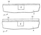
- FIG. 1shows a cross-sectional fragmentary view of a deposition substrate at one processing step in accordance with an aspect of the invention.
- FIG. 2shows the deposition substrate of FIG. 1 at a processing step subsequent to that shown in FIG. 1 .
- FIG. 3shows the deposition substrate of FIG. 1 at an alternative processing step subsequent to that shown in FIG. 1 .
- FIG. 4shows the deposition substrate of FIG. 1 at a processing step subsequent to that shown in FIG. 3 .
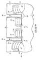
- FIG. 5shows a cross-sectional fragmentary view of a semiconductive wafer portion at a processing step in accordance with an aspect of the invention.
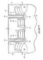
- FIG. 6shows the semiconductive wafer of FIG. 5 at a processing step subsequent to that shown in FIG. 5 .
- One aspect of the inventionprovides a deposition method that includes forming a nucleation layer over a substrate, forming a layer of a first substance at least one monolayer thick chemisorbed on the nucleation layer, and forming a layer of a second substance at least one monolayer thick chemisorbed. on the first substance.
- a chemisorption product of the first and second substancemay include silicon and nitrogen, or aluminum and oxygen, or tantalum and oxygen.
- the nucleation layermay comprise silicon nitride, aluminum oxide, or tantalum oxide.
- a thickness of the. nucleation layermay be less than about 20 Angstroms.
- a low selectivity deposition methodin another aspect of the invention, includes forming a first part of a nucleation layer on a first surface of a substrate and forming a second part of a nucleation layer. on a second surface of a substrate.
- a deposition layermay then be formed on the first and second parts of the nucleation layer substantially non-selectively on the first part of the nucleation layer compared to the second part.
- Substantially non-selective depositionoccurs even though the first and second surfaces of the substrate exhibit a property of the deposition layer forming less readily on the first surface compared to the second surface.
- the deposition layermay comprise a monolayer of a first chemisorbed specie.
- the deposition layermay be formed by chemical vapor deposition or atomic layer deposition.
- the first and second part of the nucleation layermay be formed simultaneously.
- the nucleation layermay form substantially non-selectively on the first surface of the substrate compared to the second surface.
- a thickness of the first part of the nucleation layermay be. greater than 50% of a thickness of the second part, or even greater than 80% of the thickness of the second part.
- the first surface of the substratemay exhibit a property of chemisorbing the first specie at a slower rate compared, to the second surface.
- a deposition methodin another aspect, includes simultaneously forming a first part of a nucleation layer on an insulative oxide material and a second part of the nucleation layer on a semiconductive material.
- the nucleation layermay be contacted with an initiation precursor.
- An initiation layer at last one monolayer thickmay be formed on the first and second parts of the nucleation layer substantially non-selectively on the first part of the nucleation layer compared to the second part.
- a nucleation layercomprising silicon and nitrogen may be formed substantially non-selectively on a first and a second surface of a substrate.
- a monolayer of a first substancemay be chemisorbed on the nucleation layer.
- a monolayer of a second substancemay be chemisorbed on the first substance, wherein a chemisorption product of the first and second substances comprises silicon nitride.
- a deposition methodmay include atomic layer depositing a nucleation substance chemisorbed on a first surface and a second surface of a substrate substantially non-selectively.
- the first surfacemay exhibit a property of chemisorbing an atomic layer deposition precursor at a slower rate compared to the second surface.
- the nucleation substancemay exhibit a property of chemisorbing the precursor at an approximately equal rate over the first surface compared to over the second surface.
- Atomic layer depositioninvolves formation of successive atomic layers on a substrate. Such layers may comprise an epitaxial, polycrystalline, amorphous, etc. material. ALD may also be referred to as atomic layer epitaxy, atomic layer processing, etc. Further, the invention may encompass other deposition methods not traditionally referred to as ALD, for example, chemical vapor deposition (CVD), but nevertheless including the method steps described herein. The deposition methods herein may be described in the context of formation on a semiconductor wafer. However, the invention encompasses deposition on a variety of substrates besides semiconductor substrates.
- semiconductor substrateor “semiconductive substrate” is defined to mean any construction comprising semiconductive material, including, but not limited to, bulk semiconductive materials such as a semiconductive wafer (either alone or in assemblies comprising other materials thereon), and semiconductive material layers (either alone or in assemblies comprising other materials).
- substraterefers to any supporting structure, including, but not limited to, the semiconductive substrates described above.
- ALDincludes exposing an initial substrate to a first chemical specie to accomplish chemisorption of the specie onto the substrate.
- the chemisorptionforms a monolayer that is uniformly one atom or molecule thick on the entire exposed initial substrate. Practically, as further described below, chemisorption might not occur on all portions of the substrate. Nevertheless, such an imperfect monolayer is still a monolayer in the context of this document.
- the first specieis purged from over the substrate and a second chemical specie is provided to chemisorb onto the first monolayer of the first specie.
- the second specieis then purged and the steps are repeated with exposure of the second specie monolayer to the first specie.
- the two monolayersmay be of the same specie.
- additional speciesmay be successively chemisorbed and purged just as described for the first and second species.
- ALDis often described as a self-limiting process, in that a finite number of sites exist on a substrate to which the first specie may form chemical bonds. The second specie might only bond to the first specie ad thus may also be self-limiting. Once all of the finite number of sites on a substrate are bonded with a first specie, the first specie will often not bond to other of the first specie already bonded with the substrate.
- process conditionscan be varied in ALD as discussed below to promote such bonding and render ALD not self-limiting. Accordingly, ALD may also encompass a specie forming other than one monolayer at a time by stacking of a specie, forming a layer more than one atom or molecule thick.
- ALDatomic layer deposition
- materials that may be deposited by ALDinclude silicon nitride, zirconium oxide, tantalum oxide, aluminum oxide, and others.
- specie pairs for ALD of silicon nitrideinclude NH 3 /SiHCl 3 and others.
- ALDoffers a variety of advantages and improvements over other methods of forming materials on a substrate.
- ALD layers formed on a substratemay also possess thickness variations caused by variations in the composition and/or surface properties of the underlying substrate. Such disadvantage can limit the application of ALD methods to exclude applications where ALD might otherwise be particularly advantageous.
- ALDatomic layer deposition
- a layer of polysiliconmay include isolated areas where a surface defect reduces the likelihood of formation of a material on the surface defect by ALD.
- the differences in deposition ratemay create thickness variations in the deposited material.
- a desiremay exist to simultaneously deposit a material over two dissimilar types of substrate.
- a surface of borophosphosilicate glass (BPSG) and a surface of polysiliconcan be two dissimilar types of substrate. Observations indicate that formation of silicon nitride by ALD simultaneously on BPSG and polysilicon produces a thickness variation in the deposited silicon nitride.
- the thickness of the silicon nitride deposited on the BPSGcan be less than 50% of the thickness of the silicon nitride deposited on the polysilicon.
- a variety of other circumstancesare conceivable wherein a substantially uniform thickness of a material deposited by ALD is desired on dissimilar portions of a substrate, such as a semiconductive substrate compared to an insulative or a conductive substrate.
- a deposition methodmay include forming a nucleation layer over a substrate.
- the nucleation layermay exhibit a first value of an electrical property, for example, dielectric constant, conductivity, current leakage, permitivity, capacitance, etc.
- a substrate 2is shown including a first part 4 and a second part 6 .
- Second part 6may comprise a composition different from first part 4 or second part 6 may comprise the same composition but exhibit a property that causes deposition to occur more readily on second part 6 compared to first part 4 .
- FIG. 2shows a deposition layer 8 formed on first part 4 and second part 6 of substrate 2 .
- the thickness of deposition layer 8 that is over first part 4is less than 50% of a thickness of deposition layer 8 that is over second part 6 .
- the nucleation layermay operate to provide at least somewhat uniform surface properties for the deposition and decrease thickness variations such as shown in FIG. 2 . Even so, a nucleation layer may interface between a substrate. and a subsequently deposited deposition layer in a manner that only insignificantly influences the overall properties of the combined nucleation and deposition layer. That is, a deposition layer deposited directly on a substrate without a nucleation layer generally will possess some designated purpose or designated property. A nucleation layer may be selected such that only an insignificant impact is imposed upon the desired purpose or property.
- a nucleation layermay find advantageous use even in circumstances where a substrate possesses both a homogeneous composition and homogeneous surface properties.
- Such a nucleation layermay interface between a substrate and a deposition layer to enhance the rate of formation of the deposition layer or to otherwise provide an advantageous property or result.
- a first monolayer of a first chemisorbed speciemay form more rapidly over BPSG if a nucleation layer is first formed.
- the thickness of a nucleation layermay also influence its suitability.
- ALDis selected with the desire to form high quality very thin layers of material.
- a nucleation layermay be selected that only insignificantly impacts the deposition layer.
- the potential advantages of selecting ALD for forming a layer of the materialmay be diminished.
- a nucleation layer having a thickness of only one atom or moleculemay be formed to minimize any potential impact.
- a more thick nucleation layermay also ii provide little impact.
- a thickness of a nucleation layermay comprise less than about 20 Angstroms. Further, the thickness may comprise less than about 6 Angstroms. Still further, the thickness may comprise about 2.5 Angstroms.
- a monolayer of silicon nitridemay comprise about 2.5 Angstroms.
- a nucleation layer 10is shown formed over substrate 2 .
- substrate 2includes first part 4 on which deposition occurs less readily compared to second part 6 .
- first part 4on which deposition occurs less readily compared to second part 6 .
- such a propertymay be caused by first part 4 possessing a different composition than second part 6 or exhibiting a different surface property than second part 6 .
- Suchis in contrast to another advantageous use of nucleation layer 10 even when a substrate possesses homogeneous composition and exhibits homogeneous surface properties.
- a deposition layer 12may be formed on nucleation layer 10 without the thickness variation illustrated in FIG. 2 .
- Deposition layer 12may be formed by any deposition method presently known to those skilled in the art or later developed, but preferably by ALD as defined herein. Other deposition methods may also be suitable.
- a suitable deposition methodmay include forming a layer of a first substance at least one monolayer thick chemisorbed on the nucleation layer and forming a layer of a second substance at least one monolayer thick chemisorbed on the first substance.
- a chemisorption product of the layersmay comprise deposition layer 12 .
- Deposition layer 12may exhibit a second value of the electrical property exhibited by nucleation layer 10 at a first value. Examples of electrical properties are listed above. Deposition layer 12 and nucleation layer 10 combined may exhibit a third value of the electrical property that is more near the second value than the first value. The third value and second value may be approximately equal.
- the methodmay include at least once additionally forming successive monolayers of the first substance and the second substance. In such case, all monolayers may be comprised by deposition layer 12 .
- Nucleation layer 10may possess a variety of compositions and exhibit a variety of properties and still comprise a suitable interface between deposition layer 12 and a substrate, for example substrate 2 .
- nucleation layer 10may comprise a compound the same as a deposition product of the first and second substances in the chemisorbed monolayers described above.
- a chemisorption product of the first and second substancemay comprise silicon and nitrogen.
- a nucleation layermay also comprise silicon and nitrogen. More specifically, the chemisorption product that produces deposition layer 12 may comprise silicon nitride and nucleation 10 may also comprise silicon nitride.
- a nucleation layermay comprise an approximately homogeneous composition. In an approximately homogeneous composition, only insignificant differences in composition exist throughout the nucleation layer. However, a nucleation layer may also possess a composition wherein one part of the nucleation layer differs from a composition of another part of the nucleation layer as to a component, a proportion of a component, or both.
- a nucleation layerthat comprises silicon nitride but a part of the nucleation layer further comprises oxygen, for example, comprising silicon oxynitride.
- a deposition methodin another aspect of the invention, includes forming a first part of a nucleation layer on a first surface of a substrate and forming a second part of a nucleation layer on a second surface of the substrate. Forming the first and second part of the nucleation layer may occur simultaneously. Alternatively, the first part and the second part of the nucleation layer may be formed separately. When formed simultaneously, the nucleation layer may form substantially non-selectively on the first surface of the substrate compared to the second surface.
- the thickness of a nucleation layeris one measure of the selectivity of forming a nucleation layer.
- non-selective formation of a nucleation layermay occur when the thickness of the first part of the nucleation layer on the first surface of a substrate is greater than 50% of the thickness of the second part formed on the second surface of the substrate. More particularly, non-selective formation occurs when the thickness of the first part is greater than 80% of the thickness of the second part.
- One advantage of the present inventionis that substantially nonselective formation of a nucleation layer may occur even though ALD on the same surface occurs selectively, that is, at a greater than 2 to 1 ratio of deposition rate.
- Such a depositionmay produce a deposition layer having a thickness over the first surface that is less than 50% of the thickness over the second surface.
- the second part of the nucleation layer on the second surface of the substratemay comprise a plurality of components also comprised by the first part.
- the first and second parts of the nucleation layermay comprise silicon nitride.
- the first and second parts of the nucleation layermay even consist essentially of the same components in approximately same proportions.
- the first and second parts of the nucleation layermay comprise an approximately homogeneous composition.
- the composition of the first part of the nucleation layermay also differ from the composition of the second part of the nucleation layer. In such a circumstance, the first and second parts of the nucleation layer may still both comprise silicon nitride.
- the first partmay further comprise oxygen, for example, as in silicon oxynitride.
- the present aspect of the inventionmay further include forming a monolayer of a first chemisorbed specie on the first and second parts of the nucleation layer substantially non-selectively on the first part of the nucleation layer compared to the second part.
- Such non-selective formation of a monolayer of a first chemisorbed speciemay occur even though the first surface of the substrate exhibits a property of chemisorbing the first specie at a slower rate compared to the second surface.
- the nucleation layermay operate to interface between a deposition layer and a substrate to alter properties such that deposition occurs substantially non-selectively.
- the deposition methodmay further comprise forming a monolayer of a second chemisorbed specie different from the first specie on the first specie layer.
- the nucleation layercomprise a material also comprised by the first and second specie layers combined.
- the first and second specie layers, in combinationmay comprise silicon and nitrogen.
- the nucleation layermay similarly comprise silicon and nitrogen.
- a deposition methodin another aspect of the invention, includes simultaneously forming a first part of a nucleation layer on an insulative oxide material and a second part of the nucleation layer on a semiconductive material. The nucleation layer may then be contacted with an initiation precursor. The method further includes forming an initiation layer at least one monolayer thick on the first and second parts of the nucleation layer substantially non-selectively on the first part of the nucleation layer compared to the second part. The method further may comprise contacting the initiation layer with a deposition precursor and forming a deposition layer at least one monolayer thick on the initiation layer.
- the method selectedmay be in situ with regard to subsequent formation of the deposition layer or it may be ex situ.
- ALDmay itself comprise one example of an in situ method. For example, a substrate may be placed in a first chamber and the first and second parts of a nucleation layer formed thereon by ALD. Without removing the substrate from the chamber, a monolayer of a first chemisorbed precursor may then be formed on the nucleation layer also by ALD.
- ALDatomic layer deposition
- temperaturesmay remain below about 550 Celsius (° C.) and pressure may remain below about 20 Torr.
- the increased temperature, pressure, or bothcorrespondingly increases the likelihood that a deposition specie will chemisorb substantially non-selectively on the first and second surfaces of the substrate as described above and shown in FIG. 3 .
- ALDatomic layer deposition
- traditional ALD of silicon nitridemay occur at a temperature of from about 400° C. to about 550° C. and a pressure of less than about 100 milliTorr.
- a temperature of from about 400° C. to about 550° C. and a pressure of less than about 100 milliTorrmay be used as a source of silicon.
- CVDchemical vapor deposition
- the general technology of CVDincludes a variety of more specific processes, including, but not limited to, plasma enhanced CVD and others.
- CVDis commonly used to form non-selectively a complete, deposited material on a substrate.
- One characteristic of CVDis the simultaneous presence of multiple species in the deposition chamber that react to form the deposited material. Such condition is contrasted with the purging criteria for traditional ALD wherein a substrate is contacted with a single deposition specie and chemisorbs to a substrate or previously deposited specie.
- a nontraditional ALD process regimemay provide simultaneously contacted species of a type or under conditions such that ALD chemisorption, rather than CVD reaction occurs.
- U.S. patent application Ser. No. 09/619,449 filed Jul. 19, 2000 by Garo J. Derderian and Gurtej S. Sandhu entitled “Deposition Methods” and assigned to Micron Technologies, Inc.discloses a nontraditional ALD process and is herein incorporated by reference.
- Derderian et al.describe a deposition method including contacting a substrate with a first initiation precursor and forming a first portion of an initiation layer on the substrate. At least a part of the substrate is contacted with a second initiation precursor different from the first initiation precursor and a second portion of the initiation layer is formed on the substrate.
- the inventionmay include simultaneously contacting a substrate with a plurality of initiation precursors, forming on the substrate an initiation layer comprising components derived from each of the plurality of initiation precursors.
- the plurality of initiation precursorsdo not react together as in CVD. Rather, they chemisorb to the substrate, providing a surface onto which a deposition specie may next chemisorb to form a complete layer of desired material.
- deposition of the materialoccurs largely independent of the composition or surface properties of an underlying substrate.
- deposition ratecan be a frequent issue in performing CVD.
- High deposition ratesare often desired to increase production output as long as such rates do not significantly diminish the quality of a deposited material. Accordingly, depending on the particular type of CVD technique, a process regime is selected that produces as high a deposition rate as is possible without significant negative impacts on material quality.
- deposition rateis a less significant issue. Accordingly, observation indicates that lower pressures, temperatures, plasma intensities, reactant concentrations, etc., than would otherwise be traditionally accepted may be used to produce a nucleation layer.
- CVD of a nucleation layermay thus occur at a deposition rate that conventionally might not qualify for a suitable CVD process.
- traditional CVD of silicon nitridemay occur at a temperature between about 600° C. to about 800° C. and a pressure between about 100 milliTorr to about 2 Torr, depending on the selected temperature. If temperature is toward the low end of the range, then pressure is generally toward the high end of the range to stay within the traditional process regime.
- Exemplary parameters for nontraditional CVD of a nucleation layermay fall below one or both of such ranges or be in the low end of both ranges. Different ranges are conceivable, as determinable by those skilled in the art, depending on deposition precursors, substrate composition, surface properties, and other factors.
- CVDis typically a non-selective form of deposition
- the non-traditional process regimecan produce a suitable nucleation layer having a thickness of one atom or molecule or more.
- formation of an approximately 4 to 6 Angstrom silicon nitride nucleation layer from ammonia and dichlorosilane (DCS)has been achieved at a pressure of less than approximately 1.5 Torr, a temperature of approximately 645° C., and a processing time of about 2 minutes.
- the same reaction chamber or toolmay be used. both for CVD of a nucleation layer and ALD of a deposition layer.
- the hybrid structure of the CVD nucleation layer and ALD deposition layermay be formed possessing the advantageous qualities of an ALD material and such formation may be accomplished in situ.
- forming a deposition layermay occur by unconventional CVD in a process regime so far outside conventional CVD that the deposition is substantially selective. That is, multiple deposition species may contact the substrate together in the deposition chamber.
- temperature and pressureare low enough that the thickness of the deposition layer over a first part of a substrate is less than 50% of a thickness of the deposition layer over a second part, as shown in FIG. 2 .
- Exemplary parametersinclude less than about 645° C. and less than about 500 milliTorr or perhaps different ranges, as determinable by those skilled in the art, depending on above mentioned factors. In such a process regime, pressure might bear a more significant effect on selectivity compared to temperature.
- the unconventional CVD process regimemay be conducive to forming a deposition layer only about 1 to 5 atoms or molecules thick. Accordingly, by using a nucleation layer in keeping with the various aspects of the present invention, unconventional CVD may also be used to form a deposition layer.
- any of the above-described ALD or CVD techniquesmay be used.
- a substratemay be placed in a first chamber and the first and second parts of a nucleation layer formed on the substrate.
- the substratemay then be removed from the first chamber and placed in a second chamber different from the first. Formation of an ALD precursor monolayer or unconventional CVD layer may then occur in the second chamber.
- the first chambermay comprise any tool suitable for accomplishing CVD or ALD.
- the first chambermay further comprise any tool suitable for accomplishing techniques such as rapid thermal nitridation (RTN), remote plasma nitridation (RPN), techniques for accomplishing growth of a material (as opposed to deposition) on a substrate, and other techniques.
- RTN, RPN, and other techniquescan involve growth of a nucleation layer non-selectively on first and second surfaces of a substrate.
- RTNoften occurs in an ammonia ambient at a temperature of greater than 700° C. Temperature may be limited to about 800° C. in circumstances where thermal budget limitations exist.
- RPNis performed similarly except that a plasma is used to provide reactive nitrogen radicals in a manner that provides reduction of process temperature. Accordingly, RPN may be preferred in a circumstance with a sensitive thermal budget.
- Material growth techniquesmay produce a nucleation layer the composition and selectivity of which can be influenced by the composition of the underlying substrate.
- one potential substrateis one wherein first part 4 of substrate 2 in FIG. 1 comprises BPSG and second part 6 comprises polysilicon.
- BPSGcomprises silicon, oxygen, boron, and phosphorous.
- Polysiliconcomprises primarily silicon. Both materials comprise silicon, accordingly, thermal growth techniques may produce a silicon-containing material grown on the substrate.
- Nitride growth techniquesmay produce silicon nitride on both materials.
- the silicon nitride material grown on BPSGmay also include oxygen, for example, the material may comprise silicon oxynitride.
- the boron and phosphorous dopants of BPSGwill not be incorporated into the grown material.
- one part of a substratecomprises silicon and another part of the substrate does not comprise silicon.
- a nitride or other grown materialwill form on the substrate will depend on the susceptibility of the non-silicon-comprising material to such growth technique. Accordingly, a grown nucleation layer may form substantially non-selectively on a substrate or it may form selectively on a substrate depending on the criteria discussed above. Nevertheless, it is conceivable within the various aspects of the invention that an ex situ processing method may form a first and a second part of a nucleation layer simultaneously and substantially non-selectively on a first and second surface of a substrate.
- Suchmay occur even though the first surface of the substrate exhibits a property of chemisorbing a first precursor at a slower rate compared to the second surface.
- Deposition of a materialmay subsequently occur on the ex situ formed nucleation layer also substantially non-selectively.
- FIG. 5shows a semiconductive wafer construction 20 having partially formed dynamic random access memory (DRAM) cells formed thereon.
- Semiconductive wafer construction 20includes a semiconductive material 22 , for example, a bulk silicon wafer, and a field oxide 23 formed on semiconductive material 22 . Node locations 25 , 27 , and 29 are formed within semiconductive material 22 .
- Word lines 24are formed over field oxide 23 and word lines 26 are formed over semiconductive material 22 .
- An oxide layer 32 formed over word lines 24 and 26prevents diffusion of dopants within a BPSG layer 34 into word lines 24 and 26 .
- Capacitor openings 38 and 40are formed through BPSG layer 34 to expose node locations 25 and 29 , respectively.
- a storage node layer 36is formed on BPSG layer 34 and in electrical connection with node locations 25 and 29 .
- Storage node layer 36may comprise polysilicon, or more preferably rugged polysilicon.
- Rugged polysiliconmay include hemispherical grain polysilicon, spherical grain polysilicon, etc.
- Formation of silicon nitride as a capacitor dielectric on storage node layer 36is desired. Formation of silicon nitride on BPSG layer 34 as a dopant diffusion barrier is also desired. Formation of silicon nitride as a capacitor dielectric by ALD offers the advantage of a thin capacitor layer that possesses low electrical tunneling probability and low defect densities compared to traditional CVD silicon nitride. Simultaneous formation of silicon nitride over storage node layer 36 and BPSG layer 34 would also afford processing advantages. As described above, observation indicates that ALD of silicon nitride forms preferentially on polysilicon compared to BPSG.
- the various aspects of the present inventionallow formation of a nucleation layer (not shown due to its preferably small thickness) on storage node layer 36 and BPSG layer 34 followed by formation of a deposition layer 42 as shown in FIG. 6 on the nucleation layer.
- the nucleation layermay be formed simultaneously and non-selectively on storage node layer 36 and BPSG layer 34 .
- the nucleation layermay comprise silicon nitride, but may instead comprise some other compound. Accordingly, the nucleation layer may comprise a material that is not a suitable capacitor dielectric and/or dopant diffusion barrier.
- a silicon nitride nucleation layermay be formed in situ in a low pressure CVD hot wall batch reactor at about 645° C. and about 1.5 Torr. Processing time may be varied to form a layer of a thickness suitable for nucleation. Subsequently, a deposition layer may be formed on the nucleation layer within the low pressure CVD hot wall batch reactor.
- the deposition layermay be formed by ALD.
- a silicon nitride nucleation layermay be formed ex situ using RTN at about 800° C. for about 60 seconds in an ammonia ambient.
- the substrate and nucleation layermay then be removed to a deposition device suitable for the deposition layer formation, such as by, ALD.
Landscapes
- Chemical & Material Sciences (AREA)
- Engineering & Computer Science (AREA)
- Chemical Kinetics & Catalysis (AREA)
- Manufacturing & Machinery (AREA)
- Physics & Mathematics (AREA)
- Computer Hardware Design (AREA)
- Microelectronics & Electronic Packaging (AREA)
- Power Engineering (AREA)
- General Physics & Mathematics (AREA)
- Condensed Matter Physics & Semiconductors (AREA)
- General Chemical & Material Sciences (AREA)
- Materials Engineering (AREA)
- Mechanical Engineering (AREA)
- Metallurgy (AREA)
- Organic Chemistry (AREA)
- Chemical Vapour Deposition (AREA)
Abstract
Description
Claims (56)
Priority Applications (3)
| Application Number | Priority Date | Filing Date | Title |
|---|---|---|---|
| US09/643,004US7192888B1 (en) | 2000-08-21 | 2000-08-21 | Low selectivity deposition methods |
| US10/299,140US6987073B2 (en) | 2000-08-21 | 2002-11-18 | Low selectivity deposition methods |
| US11/725,740US20070190775A1 (en) | 2000-08-21 | 2007-03-19 | Low selectivity deposition methods |
Applications Claiming Priority (1)
| Application Number | Priority Date | Filing Date | Title |
|---|---|---|---|
| US09/643,004US7192888B1 (en) | 2000-08-21 | 2000-08-21 | Low selectivity deposition methods |
Related Child Applications (2)
| Application Number | Title | Priority Date | Filing Date |
|---|---|---|---|
| US10/299,140DivisionUS6987073B2 (en) | 2000-08-21 | 2002-11-18 | Low selectivity deposition methods |
| US11/725,740ContinuationUS20070190775A1 (en) | 2000-08-21 | 2007-03-19 | Low selectivity deposition methods |
Publications (1)
| Publication Number | Publication Date |
|---|---|
| US7192888B1true US7192888B1 (en) | 2007-03-20 |
Family
ID=24578966
Family Applications (3)
| Application Number | Title | Priority Date | Filing Date |
|---|---|---|---|
| US09/643,004Expired - LifetimeUS7192888B1 (en) | 2000-08-21 | 2000-08-21 | Low selectivity deposition methods |
| US10/299,140Expired - Fee RelatedUS6987073B2 (en) | 2000-08-21 | 2002-11-18 | Low selectivity deposition methods |
| US11/725,740AbandonedUS20070190775A1 (en) | 2000-08-21 | 2007-03-19 | Low selectivity deposition methods |
Family Applications After (2)
| Application Number | Title | Priority Date | Filing Date |
|---|---|---|---|
| US10/299,140Expired - Fee RelatedUS6987073B2 (en) | 2000-08-21 | 2002-11-18 | Low selectivity deposition methods |
| US11/725,740AbandonedUS20070190775A1 (en) | 2000-08-21 | 2007-03-19 | Low selectivity deposition methods |
Country Status (1)
| Country | Link |
|---|---|
| US (3) | US7192888B1 (en) |
Cited By (1)
| Publication number | Priority date | Publication date | Assignee | Title |
|---|---|---|---|---|
| US20110223320A1 (en)* | 2010-03-09 | 2011-09-15 | Zhe Song | Methods Of Forming Material Over A Substrate And Methods Of Forming Capacitors |
Families Citing this family (13)
| Publication number | Priority date | Publication date | Assignee | Title |
|---|---|---|---|---|
| US6458416B1 (en)* | 2000-07-19 | 2002-10-01 | Micron Technology, Inc. | Deposition methods |
| WO2002070142A1 (en)* | 2000-12-06 | 2002-09-12 | Angstron Systems, Inc. | Method and apparatus for improved temperature control in atomic layer deposition |
| US6878402B2 (en)* | 2000-12-06 | 2005-04-12 | Novellus Systems, Inc. | Method and apparatus for improved temperature control in atomic layer deposition |
| US7368014B2 (en)* | 2001-08-09 | 2008-05-06 | Micron Technology, Inc. | Variable temperature deposition methods |
| US6551893B1 (en)* | 2001-11-27 | 2003-04-22 | Micron Technology, Inc. | Atomic layer deposition of capacitor dielectric |
| KR100459724B1 (en)* | 2002-09-11 | 2004-12-03 | 삼성전자주식회사 | Semiconductor device having a SiN etch stopper by low temperature ALD and fabricating method the same |
| US6972473B2 (en)* | 2003-08-12 | 2005-12-06 | Tessera, Inc. | Structure and method of making an enhanced surface area capacitor |
| US9202758B1 (en)* | 2005-04-19 | 2015-12-01 | Globalfoundries Inc. | Method for manufacturing a contact for a semiconductor component and related structure |
| EP1790758A1 (en)* | 2005-11-25 | 2007-05-30 | Interuniversitair Microelektronica Centrum ( Imec) | Atomic layer deposition (ald) method for producing a high quality layer |
| US20100099251A1 (en)* | 2008-10-22 | 2010-04-22 | Applied Materials, Inc. | Method for nitridation pretreatment |
| TWI545628B (en)* | 2011-06-20 | 2016-08-11 | 應用材料股份有限公司 | N-type metal film deposition with starting layer |
| US10388515B2 (en) | 2015-11-16 | 2019-08-20 | Taiwan Semiconductor Manufacturing Company, Ltd. | Treatment to control deposition rate |
| US11830730B2 (en)* | 2017-08-29 | 2023-11-28 | Asm Ip Holding B.V. | Layer forming method and apparatus |
Citations (68)
| Publication number | Priority date | Publication date | Assignee | Title |
|---|---|---|---|---|
| US3785853A (en) | 1972-05-24 | 1974-01-15 | Unicorp Inc | Continuous deposition reactor |
| US4058430A (en) | 1974-11-29 | 1977-11-15 | Tuomo Suntola | Method for producing compound thin films |
| US4369105A (en) | 1981-03-25 | 1983-01-18 | The Dow Chemical Company | Substituted cobalt oxide spinels |
| US4789648A (en)* | 1985-10-28 | 1988-12-06 | International Business Machines Corporation | Method for producing coplanar multi-level metal/insulator films on a substrate and for forming patterned conductive lines simultaneously with stud vias |
| US4831003A (en) | 1987-09-14 | 1989-05-16 | Exxon Research And Engineering Company | Catalyst composition and process of making |
| US4913090A (en) | 1987-10-02 | 1990-04-03 | Mitsubishi Denki Kabushiki Kaisha | Chemical vapor deposition apparatus having cooling heads adjacent to gas dispersing heads in a single chamber |
| US5116640A (en) | 1989-10-24 | 1992-05-26 | Sharp Kabushiki Kaisha | Process for preparing an electroluminescent device |
| US5124278A (en)* | 1990-09-21 | 1992-06-23 | Air Products And Chemicals, Inc. | Amino replacements for arsine, antimony and phosphine |
| JPH05251339A (en) | 1991-08-14 | 1993-09-28 | Fujitsu Ltd | Semiconductor substrate and manufacturing method thereof |
| US5270247A (en) | 1991-07-12 | 1993-12-14 | Fujitsu Limited | Atomic layer epitaxy of compound semiconductor |
| US5273930A (en)* | 1992-09-03 | 1993-12-28 | Motorola, Inc. | Method of forming a non-selective silicon-germanium epitaxial film |
| US5281274A (en) | 1990-06-22 | 1994-01-25 | The United States Of America As Represented By The Secretary Of The Navy | Atomic layer epitaxy (ALE) apparatus for growing thin films of elemental semiconductors |
| US5366953A (en)* | 1991-03-19 | 1994-11-22 | Conductus, Inc. | Method of forming grain boundary junctions in high temperature superconductor films |
| US5366555A (en) | 1990-06-11 | 1994-11-22 | Kelly Michael A | Chemical vapor deposition under a single reactor vessel divided into separate reaction regions with its own depositing and exhausting means |
| US5413671A (en) | 1993-08-09 | 1995-05-09 | Advanced Micro Devices, Inc. | Apparatus and method for removing deposits from an APCVD system |
| US5462603A (en) | 1993-06-24 | 1995-10-31 | Tokyo Electron Limited | Semiconductor processing apparatus |
| US5480818A (en) | 1992-02-10 | 1996-01-02 | Fujitsu Limited | Method for forming a film and method for manufacturing a thin film transistor |
| US5597609A (en) | 1994-03-09 | 1997-01-28 | Leybold Aktiengesellschaft | Process and apparatus for the continuous or semi-continuous coating of eyeglass lenses |
| US5597756A (en)* | 1995-06-21 | 1997-01-28 | Micron Technology, Inc. | Process for fabricating a cup-shaped DRAM capacitor using a multi-layer partly-sacrificial stack |
| US5616208A (en) | 1993-09-17 | 1997-04-01 | Tokyo Electron Limited | Vacuum processing apparatus, vacuum processing method, and method for cleaning the vacuum processing apparatus |
| EP0794568A2 (en) | 1996-03-05 | 1997-09-10 | Applied Materials, Inc. | Blanket-selective deposition of cvd aluminum and reflectivity improvement using a self-aligning ultra-thin layer |
| US5747113A (en) | 1996-07-29 | 1998-05-05 | Tsai; Charles Su-Chang | Method of chemical vapor deposition for producing layer variation by planetary susceptor rotation |
| US5879459A (en) | 1997-08-29 | 1999-03-09 | Genus, Inc. | Vertically-stacked process reactor and cluster tool system for atomic layer deposition |
| US5916365A (en) | 1996-08-16 | 1999-06-29 | Sherman; Arthur | Sequential chemical vapor deposition |
| US5929526A (en)* | 1997-06-05 | 1999-07-27 | Micron Technology, Inc. | Removal of metal cusp for improved contact fill |
| US5937300A (en) | 1994-10-12 | 1999-08-10 | Nec Corporation | Semiconductor apparatus and fabrication method thereof |
| US5985770A (en) | 1997-08-21 | 1999-11-16 | Micron Technology, Inc. | Method of depositing silicon oxides |
| US5997588A (en) | 1995-10-13 | 1999-12-07 | Advanced Semiconductor Materials America, Inc. | Semiconductor processing system with gas curtain |
| US6042652A (en)* | 1999-05-01 | 2000-03-28 | P.K. Ltd | Atomic layer deposition apparatus for depositing atomic layer on multiple substrates |
| US6060383A (en)* | 1998-08-10 | 2000-05-09 | Nogami; Takeshi | Method for making multilayered coaxial interconnect structure |
| US6066358A (en)* | 1995-11-21 | 2000-05-23 | Applied Materials, Inc. | Blanket-selective chemical vapor deposition using an ultra-thin nucleation layer |
| US6083832A (en) | 1997-10-21 | 2000-07-04 | Nec Corporation | Method of manufacturing semiconductor device |
| US6114099A (en) | 1996-11-21 | 2000-09-05 | Virginia Tech Intellectual Properties, Inc. | Patterned molecular self-assembly |
| US6139695A (en) | 1995-08-07 | 2000-10-31 | Akashic Memories Corporation | Modular deposition system having batch processing and serial thin film deposition |
| US6143659A (en) | 1997-11-18 | 2000-11-07 | Samsung Electronics, Co., Ltd. | Method for manufacturing aluminum metal interconnection layer by atomic layer deposition method |
| US6165916A (en) | 1997-09-12 | 2000-12-26 | Kabushiki Kaisha Toshiba | Film-forming method and film-forming apparatus |
| US6174377B1 (en) | 1997-03-03 | 2001-01-16 | Genus, Inc. | Processing chamber for atomic layer deposition processes |
| US6203613B1 (en) | 1999-10-19 | 2001-03-20 | International Business Machines Corporation | Atomic layer deposition with nitrate containing precursors |
| US6203618B1 (en) | 1998-03-31 | 2001-03-20 | Canon Kabushiki Kaisha | Exhaust system and vacuum processing apparatus |
| US6235571B1 (en)* | 1999-03-31 | 2001-05-22 | Micron Technology, Inc. | Uniform dielectric layer and method to form same |
| US6258690B1 (en)* | 1996-03-29 | 2001-07-10 | Nec Corporation | Method of manufacturing semiconductor device |
| US6270572B1 (en) | 1998-08-07 | 2001-08-07 | Samsung Electronics Co., Ltd. | Method for manufacturing thin film using atomic layer deposition |
| US6287965B1 (en) | 1997-07-28 | 2001-09-11 | Samsung Electronics Co, Ltd. | Method of forming metal layer using atomic layer deposition and semiconductor device having the metal layer as barrier metal layer or upper or lower electrode of capacitor |
| US6290824B1 (en) | 1992-10-28 | 2001-09-18 | Hitachi, Ltd. | Magnetic film forming system |
| US6307184B1 (en) | 1999-07-12 | 2001-10-23 | Fsi International, Inc. | Thermal processing chamber for heating and cooling wafer-like objects |
| US6306216B1 (en) | 1999-07-15 | 2001-10-23 | Moohan Co., Ltd. | Apparatus for deposition of thin films on wafers through atomic layer epitaxial process |
| US6330201B2 (en) | 1998-05-19 | 2001-12-11 | Nec Corporation | Semiconductor memory device exhibiting improved high speed and stable write operations |
| US6335561B2 (en) | 1998-01-20 | 2002-01-01 | Rohm Co., Ltd. | Semiconductor device having a passivation film |
| US6338874B1 (en)* | 1993-01-28 | 2002-01-15 | Applied Materials, Inc. | Method for multilayer CVD processing in a single chamber |
| US6355561B1 (en) | 2000-11-21 | 2002-03-12 | Micron Technology, Inc. | ALD method to improve surface coverage |
| US6358377B1 (en) | 2000-10-11 | 2002-03-19 | Guardian Industries Corp. | Apparatus for sputter-coating glass and corresponding method |
| US6368954B1 (en)* | 2000-07-28 | 2002-04-09 | Advanced Micro Devices, Inc. | Method of copper interconnect formation using atomic layer copper deposition |
| US6399921B1 (en) | 1996-06-17 | 2002-06-04 | Mattson Technology, Inc. | System and method for thermal processing of a semiconductor substrate |
| US20020066411A1 (en) | 2000-12-06 | 2002-06-06 | Chiang Tony P. | Method and apparatus for improved temperature control in atomic layer deposition |
| US6447908B2 (en) | 1996-12-21 | 2002-09-10 | Electronics And Telecommunications Research Institute | Method for manufacturing phosphor-coated particles and method for forming cathodoluminescent screen using the same for field emission display |
| US20020125516A1 (en) | 2000-08-30 | 2002-09-12 | Marsh Eugene P. | RuSixOy-containing adhesion layers and process for fabricating the same |
| US6458416B1 (en)* | 2000-07-19 | 2002-10-01 | Micron Technology, Inc. | Deposition methods |
| US6479902B1 (en)* | 2000-06-29 | 2002-11-12 | Advanced Micro Devices, Inc. | Semiconductor catalytic layer and atomic layer deposition thereof |
| US6500763B2 (en)* | 1999-12-14 | 2002-12-31 | Samsung Electronics Co., Ltd. | Method for manufacturing an electrode of a capacitor |
| US6620723B1 (en) | 2000-06-27 | 2003-09-16 | Applied Materials, Inc. | Formation of boride barrier layers using chemisorption techniques |
| US6627503B2 (en) | 2000-02-11 | 2003-09-30 | Sharp Laboratories Of America, Inc. | Method of forming a multilayer dielectric stack |
| US6630201B2 (en) | 2001-04-05 | 2003-10-07 | Angstron Systems, Inc. | Adsorption process for atomic layer deposition |
| US6727169B1 (en) | 1999-10-15 | 2004-04-27 | Asm International, N.V. | Method of making conformal lining layers for damascene metallization |
| US20040097022A1 (en)* | 2002-05-07 | 2004-05-20 | Werkhoven Christiaan J. | Silicon-on-insulator structures and methods |
| US20050101119A1 (en) | 2003-11-06 | 2005-05-12 | Taiwan Semiconductor Manufacturing Co., Ltd. | Insulating layer having graded densification |
| US20050124171A1 (en) | 2003-07-07 | 2005-06-09 | Vaartstra Brian A. | Method of forming trench isolation in the fabrication of integrated circuitry |
| US20050124158A1 (en) | 2003-10-15 | 2005-06-09 | Lopatin Sergey D. | Silver under-layers for electroless cobalt alloys |
| US20050124153A1 (en) | 1999-10-02 | 2005-06-09 | Uri Cohen | Advanced seed layery for metallic interconnects |
Family Cites Families (16)
| Publication number | Priority date | Publication date | Assignee | Title |
|---|---|---|---|---|
| US6319522B1 (en) | 1990-07-13 | 2001-11-20 | Gropep Limited | Growth-promoting agent |
| US5112881A (en)* | 1990-08-24 | 1992-05-12 | University Of Lowell | Photocrosslinked second order nonlinear optical polymers |
| US5413871A (en)* | 1993-02-25 | 1995-05-09 | General Electric Company | Thermal barrier coating system for titanium aluminides |
| US5747115A (en)* | 1993-09-30 | 1998-05-05 | The United States Of America As Represented By The Secretary Of The Navy | UV-curable and non-volatile pigmented coatings |
| US5500555A (en)* | 1994-04-11 | 1996-03-19 | Lsi Logic Corporation | Multi-layer semiconductor package substrate with thermally-conductive prepeg layer |
| JP3058251B2 (en)* | 1996-04-17 | 2000-07-04 | オリンパス光学工業株式会社 | Illumination optics |
| US6142059A (en) | 1996-11-27 | 2000-11-07 | Case Corporation | Method and apparatus for sensing the orientation of a mechanical actuator |
| US5878458A (en) | 1997-06-23 | 1999-03-09 | Higginbotham; William Earl | Electronic card lock cleaner |
| JP3371775B2 (en) | 1997-10-31 | 2003-01-27 | 株式会社日立製作所 | Polishing method |
| WO1999028290A1 (en)* | 1997-12-03 | 1999-06-10 | Massachusetts Institute Of Technology | Synthesis of oligoarylamines, and uses and reagents related thereto |
| US6203619B1 (en) | 1998-10-26 | 2001-03-20 | Symetrix Corporation | Multiple station apparatus for liquid source fabrication of thin films |
| US7094690B1 (en)* | 2000-08-31 | 2006-08-22 | Micron Technology, Inc. | Deposition methods and apparatuses providing surface activation |
| US6420230B1 (en)* | 2000-08-31 | 2002-07-16 | Micron Technology, Inc. | Capacitor fabrication methods and capacitor constructions |
| WO2002103103A2 (en)* | 2001-06-18 | 2002-12-27 | Honeywell International Inc. | Fluorine-containing compounds and polymers derived therefrom |
| US7368014B2 (en)* | 2001-08-09 | 2008-05-06 | Micron Technology, Inc. | Variable temperature deposition methods |
| US6778229B2 (en)* | 2001-10-02 | 2004-08-17 | Fujitsu Display Technologies Corporation | Liquid crystal display device and method of fabricating the same |
- 2000
- 2000-08-21USUS09/643,004patent/US7192888B1/ennot_activeExpired - Lifetime
- 2002
- 2002-11-18USUS10/299,140patent/US6987073B2/ennot_activeExpired - Fee Related
- 2007
- 2007-03-19USUS11/725,740patent/US20070190775A1/ennot_activeAbandoned
Patent Citations (70)
| Publication number | Priority date | Publication date | Assignee | Title |
|---|---|---|---|---|
| US3785853A (en) | 1972-05-24 | 1974-01-15 | Unicorp Inc | Continuous deposition reactor |
| US4058430A (en) | 1974-11-29 | 1977-11-15 | Tuomo Suntola | Method for producing compound thin films |
| US4369105A (en) | 1981-03-25 | 1983-01-18 | The Dow Chemical Company | Substituted cobalt oxide spinels |
| US4789648A (en)* | 1985-10-28 | 1988-12-06 | International Business Machines Corporation | Method for producing coplanar multi-level metal/insulator films on a substrate and for forming patterned conductive lines simultaneously with stud vias |
| US4831003A (en) | 1987-09-14 | 1989-05-16 | Exxon Research And Engineering Company | Catalyst composition and process of making |
| US4913090A (en) | 1987-10-02 | 1990-04-03 | Mitsubishi Denki Kabushiki Kaisha | Chemical vapor deposition apparatus having cooling heads adjacent to gas dispersing heads in a single chamber |
| US5116640A (en) | 1989-10-24 | 1992-05-26 | Sharp Kabushiki Kaisha | Process for preparing an electroluminescent device |
| US5366555A (en) | 1990-06-11 | 1994-11-22 | Kelly Michael A | Chemical vapor deposition under a single reactor vessel divided into separate reaction regions with its own depositing and exhausting means |
| US5281274A (en) | 1990-06-22 | 1994-01-25 | The United States Of America As Represented By The Secretary Of The Navy | Atomic layer epitaxy (ALE) apparatus for growing thin films of elemental semiconductors |
| US5124278A (en)* | 1990-09-21 | 1992-06-23 | Air Products And Chemicals, Inc. | Amino replacements for arsine, antimony and phosphine |
| US5366953A (en)* | 1991-03-19 | 1994-11-22 | Conductus, Inc. | Method of forming grain boundary junctions in high temperature superconductor films |
| US5270247A (en) | 1991-07-12 | 1993-12-14 | Fujitsu Limited | Atomic layer epitaxy of compound semiconductor |
| JPH05251339A (en) | 1991-08-14 | 1993-09-28 | Fujitsu Ltd | Semiconductor substrate and manufacturing method thereof |
| US5480818A (en) | 1992-02-10 | 1996-01-02 | Fujitsu Limited | Method for forming a film and method for manufacturing a thin film transistor |
| US5273930A (en)* | 1992-09-03 | 1993-12-28 | Motorola, Inc. | Method of forming a non-selective silicon-germanium epitaxial film |
| US6290824B1 (en) | 1992-10-28 | 2001-09-18 | Hitachi, Ltd. | Magnetic film forming system |
| US6338874B1 (en)* | 1993-01-28 | 2002-01-15 | Applied Materials, Inc. | Method for multilayer CVD processing in a single chamber |
| US5462603A (en) | 1993-06-24 | 1995-10-31 | Tokyo Electron Limited | Semiconductor processing apparatus |
| US5413671A (en) | 1993-08-09 | 1995-05-09 | Advanced Micro Devices, Inc. | Apparatus and method for removing deposits from an APCVD system |
| US5616208A (en) | 1993-09-17 | 1997-04-01 | Tokyo Electron Limited | Vacuum processing apparatus, vacuum processing method, and method for cleaning the vacuum processing apparatus |
| US5597609A (en) | 1994-03-09 | 1997-01-28 | Leybold Aktiengesellschaft | Process and apparatus for the continuous or semi-continuous coating of eyeglass lenses |
| US5937300A (en) | 1994-10-12 | 1999-08-10 | Nec Corporation | Semiconductor apparatus and fabrication method thereof |
| US5597756A (en)* | 1995-06-21 | 1997-01-28 | Micron Technology, Inc. | Process for fabricating a cup-shaped DRAM capacitor using a multi-layer partly-sacrificial stack |
| US6139695A (en) | 1995-08-07 | 2000-10-31 | Akashic Memories Corporation | Modular deposition system having batch processing and serial thin film deposition |
| US5997588A (en) | 1995-10-13 | 1999-12-07 | Advanced Semiconductor Materials America, Inc. | Semiconductor processing system with gas curtain |
| US6066358A (en)* | 1995-11-21 | 2000-05-23 | Applied Materials, Inc. | Blanket-selective chemical vapor deposition using an ultra-thin nucleation layer |
| EP0794568A2 (en) | 1996-03-05 | 1997-09-10 | Applied Materials, Inc. | Blanket-selective deposition of cvd aluminum and reflectivity improvement using a self-aligning ultra-thin layer |
| US6258690B1 (en)* | 1996-03-29 | 2001-07-10 | Nec Corporation | Method of manufacturing semiconductor device |
| US6399921B1 (en) | 1996-06-17 | 2002-06-04 | Mattson Technology, Inc. | System and method for thermal processing of a semiconductor substrate |
| US5747113A (en) | 1996-07-29 | 1998-05-05 | Tsai; Charles Su-Chang | Method of chemical vapor deposition for producing layer variation by planetary susceptor rotation |
| US5916365A (en) | 1996-08-16 | 1999-06-29 | Sherman; Arthur | Sequential chemical vapor deposition |
| US6114099A (en) | 1996-11-21 | 2000-09-05 | Virginia Tech Intellectual Properties, Inc. | Patterned molecular self-assembly |
| US6447908B2 (en) | 1996-12-21 | 2002-09-10 | Electronics And Telecommunications Research Institute | Method for manufacturing phosphor-coated particles and method for forming cathodoluminescent screen using the same for field emission display |
| US6174377B1 (en) | 1997-03-03 | 2001-01-16 | Genus, Inc. | Processing chamber for atomic layer deposition processes |
| US5929526A (en)* | 1997-06-05 | 1999-07-27 | Micron Technology, Inc. | Removal of metal cusp for improved contact fill |
| US6287965B1 (en) | 1997-07-28 | 2001-09-11 | Samsung Electronics Co, Ltd. | Method of forming metal layer using atomic layer deposition and semiconductor device having the metal layer as barrier metal layer or upper or lower electrode of capacitor |
| US5985770A (en) | 1997-08-21 | 1999-11-16 | Micron Technology, Inc. | Method of depositing silicon oxides |
| US5879459A (en) | 1997-08-29 | 1999-03-09 | Genus, Inc. | Vertically-stacked process reactor and cluster tool system for atomic layer deposition |
| US6165916A (en) | 1997-09-12 | 2000-12-26 | Kabushiki Kaisha Toshiba | Film-forming method and film-forming apparatus |
| US6083832A (en) | 1997-10-21 | 2000-07-04 | Nec Corporation | Method of manufacturing semiconductor device |
| US6143659A (en) | 1997-11-18 | 2000-11-07 | Samsung Electronics, Co., Ltd. | Method for manufacturing aluminum metal interconnection layer by atomic layer deposition method |
| US6335561B2 (en) | 1998-01-20 | 2002-01-01 | Rohm Co., Ltd. | Semiconductor device having a passivation film |
| US6203618B1 (en) | 1998-03-31 | 2001-03-20 | Canon Kabushiki Kaisha | Exhaust system and vacuum processing apparatus |
| US6330201B2 (en) | 1998-05-19 | 2001-12-11 | Nec Corporation | Semiconductor memory device exhibiting improved high speed and stable write operations |
| US6270572B1 (en) | 1998-08-07 | 2001-08-07 | Samsung Electronics Co., Ltd. | Method for manufacturing thin film using atomic layer deposition |
| US6060383A (en)* | 1998-08-10 | 2000-05-09 | Nogami; Takeshi | Method for making multilayered coaxial interconnect structure |
| US6235571B1 (en)* | 1999-03-31 | 2001-05-22 | Micron Technology, Inc. | Uniform dielectric layer and method to form same |
| US6042652A (en)* | 1999-05-01 | 2000-03-28 | P.K. Ltd | Atomic layer deposition apparatus for depositing atomic layer on multiple substrates |
| US6307184B1 (en) | 1999-07-12 | 2001-10-23 | Fsi International, Inc. | Thermal processing chamber for heating and cooling wafer-like objects |
| US6306216B1 (en) | 1999-07-15 | 2001-10-23 | Moohan Co., Ltd. | Apparatus for deposition of thin films on wafers through atomic layer epitaxial process |
| US20050124153A1 (en) | 1999-10-02 | 2005-06-09 | Uri Cohen | Advanced seed layery for metallic interconnects |
| US6727169B1 (en) | 1999-10-15 | 2004-04-27 | Asm International, N.V. | Method of making conformal lining layers for damascene metallization |
| US6203613B1 (en) | 1999-10-19 | 2001-03-20 | International Business Machines Corporation | Atomic layer deposition with nitrate containing precursors |
| US6500763B2 (en)* | 1999-12-14 | 2002-12-31 | Samsung Electronics Co., Ltd. | Method for manufacturing an electrode of a capacitor |
| US6627503B2 (en) | 2000-02-11 | 2003-09-30 | Sharp Laboratories Of America, Inc. | Method of forming a multilayer dielectric stack |
| US6620723B1 (en) | 2000-06-27 | 2003-09-16 | Applied Materials, Inc. | Formation of boride barrier layers using chemisorption techniques |
| US6479902B1 (en)* | 2000-06-29 | 2002-11-12 | Advanced Micro Devices, Inc. | Semiconductor catalytic layer and atomic layer deposition thereof |
| US6627260B2 (en) | 2000-07-19 | 2003-09-30 | Micron Technology, Inc. | Deposition methods |
| US6458416B1 (en)* | 2000-07-19 | 2002-10-01 | Micron Technology, Inc. | Deposition methods |
| US6368954B1 (en)* | 2000-07-28 | 2002-04-09 | Advanced Micro Devices, Inc. | Method of copper interconnect formation using atomic layer copper deposition |
| US20020125516A1 (en) | 2000-08-30 | 2002-09-12 | Marsh Eugene P. | RuSixOy-containing adhesion layers and process for fabricating the same |
| US6358377B1 (en) | 2000-10-11 | 2002-03-19 | Guardian Industries Corp. | Apparatus for sputter-coating glass and corresponding method |
| US6596636B2 (en) | 2000-11-21 | 2003-07-22 | Micron Technology, Inc. | ALD method to improve surface coverage |
| US6355561B1 (en) | 2000-11-21 | 2002-03-12 | Micron Technology, Inc. | ALD method to improve surface coverage |
| US20020066411A1 (en) | 2000-12-06 | 2002-06-06 | Chiang Tony P. | Method and apparatus for improved temperature control in atomic layer deposition |
| US6630201B2 (en) | 2001-04-05 | 2003-10-07 | Angstron Systems, Inc. | Adsorption process for atomic layer deposition |
| US20040097022A1 (en)* | 2002-05-07 | 2004-05-20 | Werkhoven Christiaan J. | Silicon-on-insulator structures and methods |
| US20050124171A1 (en) | 2003-07-07 | 2005-06-09 | Vaartstra Brian A. | Method of forming trench isolation in the fabrication of integrated circuitry |
| US20050124158A1 (en) | 2003-10-15 | 2005-06-09 | Lopatin Sergey D. | Silver under-layers for electroless cobalt alloys |
| US20050101119A1 (en) | 2003-11-06 | 2005-05-12 | Taiwan Semiconductor Manufacturing Co., Ltd. | Insulating layer having graded densification |
Non-Patent Citations (17)
| Title |
|---|
| Aarik et al, "Effect of Growth Conditions on Formation of TiO2-II Thin Films in Atomic Layer Deposition Process", Journal of Crystal Growth, vol. 181, Aug. 1977, pp. 259-264. |
| Aarik et al, "Effect of Growth Conditions on Formation of TiO2-II Thin Films in Atomic Layer Deposition Process", Journal of Crystal Growth, vol. 181, Aug. 1997, pp. 259-264. |
| Aarik, et al, "Control of Thin Film Structure by Reactant Pressure in Atomic Layer Deposition of TiO<SUB>2</SUB>.", Journal of Crystal Growth, 169 (1996) pp. 496-502. |
| George, et al., "Surface Chemistry for atomic Layer Growth", Journal of Physical Chemistry, vol. 100, No. 31, pp. 13121-13121, Aug. 1, 1996. |
| Kiyoko et al., Patent Abstract Application No. 04-024917 (JP 9224917, Sep./1993),"Semiconductor Substrate and Its Manufacture." |
| Ritala, et al., "Atomic Layer Epitaxy-A Valuable Tool for Nanotechnology?" Nanotechnology, vol. 10, No. 1, pp. 19-24, Mar. 1999. |
| Skarp, "ALE-Reactor for Large Area Depositions", Applied Surface Science, vol. 112, Mar. 1997, pp. 251-254. |
| Suntola, "Atomic Layer Epitaxy", Handbook of Crystal Growth, vol. 3, Chapter 14, pp. 602-663, 1994. |
| Suntola, "Surface Chemistry of Materials Deposition at Atomic Layer Level", Applied Surface Science, vol. 100/101, Mar. 1996, pp. 391-398. |
| U.S. Appl. No. 09/652,533, Sandhu (as amended Feb. 22, 2002), filed Aug. 2000. |
| U.S. Appl. No. 09/652,533, Sandhu, filed Aug. 2000. |
| U.S. Appl. No. 09/653,553, Sandhu (as amended Jan. 6, 2003 & Jun. 23, 2003) filed Aug. 31, 2000. |
| U.S. Appl. No. 09/927,230, Doan, filed Aug. 2001. |
| U.S. patent application Ser. No. 09/652,533, Sandhu et al., filed Aug. 31, 2000. |
| U.S. patent application Ser. No. 09/652,533, Sandhu, filed Aug. 2000. |
| U.S. patent application Ser. No. 09/927,230, Doan, filed Aug. 2001. |
| Vernon, S.M., "Low-cost, high-efficiency solar cells utilizing GaAs-on-Si technology." Dialog Abstract of Report No. NREL/TP-451-5353; Apr. 1993. |
Cited By (3)
| Publication number | Priority date | Publication date | Assignee | Title |
|---|---|---|---|---|
| US20110223320A1 (en)* | 2010-03-09 | 2011-09-15 | Zhe Song | Methods Of Forming Material Over A Substrate And Methods Of Forming Capacitors |
| US8501268B2 (en) | 2010-03-09 | 2013-08-06 | Micron Technology, Inc. | Methods of forming material over a substrate and methods of forming capacitors |
| US9499907B2 (en) | 2010-03-09 | 2016-11-22 | Micron Technology, Inc. | Methods of forming material over a substrate and methods of forming capacitors |
Also Published As
| Publication number | Publication date |
|---|---|
| US20030073308A1 (en) | 2003-04-17 |
| US6987073B2 (en) | 2006-01-17 |
| US20070190775A1 (en) | 2007-08-16 |
Similar Documents
| Publication | Publication Date | Title |
|---|---|---|
| US20070190775A1 (en) | Low selectivity deposition methods | |
| US7087535B2 (en) | Deposition methods | |
| US7741173B2 (en) | Method for forming a metal oxide film | |
| US7053432B2 (en) | Enhanced surface area capacitor fabrication methods | |
| US7288808B2 (en) | Capacitor constructions with enhanced surface area | |
| US7109542B2 (en) | Capacitor constructions having a conductive layer | |
| US6472323B1 (en) | Method of depositing tungsten nitride using a source gas comprising silicon | |
| US5856704A (en) | Capacitor, integrated circuitry, diffusion barriers, and method for forming an electrically conductive diffusion barrier | |
| US8481122B2 (en) | Methods of forming material over substrates | |
| US20060063346A1 (en) | Method of forming a layer and method of forming a capacitor of a semiconductor device having the same | |
| US20020058391A1 (en) | Capacitor for a semiconductor device and method for forming the same | |
| US6977407B2 (en) | Even nucleation between silicon and oxide surfaces for thin silicon nitride film growth | |
| JP2000124424A (en) | Method for forming dielectric film of capacitor having partially different thickness | |
| US6207489B1 (en) | Method for manufacturing capacitor of semiconductor memory device having tantalum oxide film | |
| GB2358284A (en) | Capacitor with tantalum oxide Ta2O5 dielectric layer and silicon nitride layer formed on lower electrode surface | |
| KR100500940B1 (en) | Method for fabricating capacitor in semiconductor device | |
| KR100583155B1 (en) | Capacitor with dielectric film mixed with hafnium, lanthanum and oxygen, and method of manufacturing same | |
| US5966624A (en) | Method of manufacturing a semiconductor structure having a crystalline layer | |
| US6734100B2 (en) | Method of forming ruthenium thin film using plasma enhanced process | |
| US20040005788A1 (en) | Method of forming a silicon nitride dielectric layer | |
| JP3045158B1 (en) | Method for forming CVD-TiN film | |
| US6140204A (en) | Process for producing a semiconductor device having hemispherical grains (HSG) | |
| KR100548846B1 (en) | Manufacturing method of capacitor with improved doping uniformity | |
| KR100546163B1 (en) | Capacitor Formation Method of Semiconductor Device | |
| KR20060011622A (en) | Capacitor of semiconductor device and manufacturing method thereof |
Legal Events
| Date | Code | Title | Description |
|---|---|---|---|
| AS | Assignment | Owner name:MICRON TECHNOLOGY, INC., IDAHO Free format text:ASSIGNMENT OF ASSIGNORS INTEREST;ASSIGNOR:MERCALDI, GARRY A.;REEL/FRAME:011031/0146 Effective date:20000811 | |
| AS | Assignment | Owner name:MICRON TECHNOLOGY, INC., IDAHO Free format text:ASSIGNMENT OF ASSIGNORS INTEREST;ASSIGNOR:MERCALDI, GARRY A.;REEL/FRAME:011527/0109 Effective date:20000811 | |
| FEPP | Fee payment procedure | Free format text:PAYOR NUMBER ASSIGNED (ORIGINAL EVENT CODE: ASPN); ENTITY STATUS OF PATENT OWNER: LARGE ENTITY | |
| STCF | Information on status: patent grant | Free format text:PATENTED CASE | |
| CC | Certificate of correction | ||
| FPAY | Fee payment | Year of fee payment:4 | |
| FPAY | Fee payment | Year of fee payment:8 | |
| AS | Assignment | Owner name:U.S. BANK NATIONAL ASSOCIATION, AS COLLATERAL AGENT, CALIFORNIA Free format text:SECURITY INTEREST;ASSIGNOR:MICRON TECHNOLOGY, INC.;REEL/FRAME:038669/0001 Effective date:20160426 Owner name:U.S. BANK NATIONAL ASSOCIATION, AS COLLATERAL AGEN Free format text:SECURITY INTEREST;ASSIGNOR:MICRON TECHNOLOGY, INC.;REEL/FRAME:038669/0001 Effective date:20160426 | |
| AS | Assignment | Owner name:MORGAN STANLEY SENIOR FUNDING, INC., AS COLLATERAL AGENT, MARYLAND Free format text:PATENT SECURITY AGREEMENT;ASSIGNOR:MICRON TECHNOLOGY, INC.;REEL/FRAME:038954/0001 Effective date:20160426 Owner name:MORGAN STANLEY SENIOR FUNDING, INC., AS COLLATERAL Free format text:PATENT SECURITY AGREEMENT;ASSIGNOR:MICRON TECHNOLOGY, INC.;REEL/FRAME:038954/0001 Effective date:20160426 | |
| AS | Assignment | Owner name:U.S. BANK NATIONAL ASSOCIATION, AS COLLATERAL AGENT, CALIFORNIA Free format text:CORRECTIVE ASSIGNMENT TO CORRECT THE REPLACE ERRONEOUSLY FILED PATENT #7358718 WITH THE CORRECT PATENT #7358178 PREVIOUSLY RECORDED ON REEL 038669 FRAME 0001. ASSIGNOR(S) HEREBY CONFIRMS THE SECURITY INTEREST;ASSIGNOR:MICRON TECHNOLOGY, INC.;REEL/FRAME:043079/0001 Effective date:20160426 Owner name:U.S. BANK NATIONAL ASSOCIATION, AS COLLATERAL AGEN Free format text:CORRECTIVE ASSIGNMENT TO CORRECT THE REPLACE ERRONEOUSLY FILED PATENT #7358718 WITH THE CORRECT PATENT #7358178 PREVIOUSLY RECORDED ON REEL 038669 FRAME 0001. ASSIGNOR(S) HEREBY CONFIRMS THE SECURITY INTEREST;ASSIGNOR:MICRON TECHNOLOGY, INC.;REEL/FRAME:043079/0001 Effective date:20160426 | |
| AS | Assignment | Owner name:JPMORGAN CHASE BANK, N.A., AS COLLATERAL AGENT, ILLINOIS Free format text:SECURITY INTEREST;ASSIGNORS:MICRON TECHNOLOGY, INC.;MICRON SEMICONDUCTOR PRODUCTS, INC.;REEL/FRAME:047540/0001 Effective date:20180703 Owner name:JPMORGAN CHASE BANK, N.A., AS COLLATERAL AGENT, IL Free format text:SECURITY INTEREST;ASSIGNORS:MICRON TECHNOLOGY, INC.;MICRON SEMICONDUCTOR PRODUCTS, INC.;REEL/FRAME:047540/0001 Effective date:20180703 | |
| AS | Assignment | Owner name:MICRON TECHNOLOGY, INC., IDAHO Free format text:RELEASE BY SECURED PARTY;ASSIGNOR:U.S. BANK NATIONAL ASSOCIATION, AS COLLATERAL AGENT;REEL/FRAME:047243/0001 Effective date:20180629 | |
| MAFP | Maintenance fee payment | Free format text:PAYMENT OF MAINTENANCE FEE, 12TH YEAR, LARGE ENTITY (ORIGINAL EVENT CODE: M1553); ENTITY STATUS OF PATENT OWNER: LARGE ENTITY Year of fee payment:12 | |
| AS | Assignment | Owner name:MICRON TECHNOLOGY, INC., IDAHO Free format text:RELEASE BY SECURED PARTY;ASSIGNOR:MORGAN STANLEY SENIOR FUNDING, INC., AS COLLATERAL AGENT;REEL/FRAME:050937/0001 Effective date:20190731 | |
| AS | Assignment | Owner name:MICRON TECHNOLOGY, INC., IDAHO Free format text:RELEASE BY SECURED PARTY;ASSIGNOR:JPMORGAN CHASE BANK, N.A., AS COLLATERAL AGENT;REEL/FRAME:051028/0001 Effective date:20190731 Owner name:MICRON SEMICONDUCTOR PRODUCTS, INC., IDAHO Free format text:RELEASE BY SECURED PARTY;ASSIGNOR:JPMORGAN CHASE BANK, N.A., AS COLLATERAL AGENT;REEL/FRAME:051028/0001 Effective date:20190731 |