US7192557B2 - Methods and systems for releasing intracellular material from cells within microfluidic samples of fluids - Google Patents
Methods and systems for releasing intracellular material from cells within microfluidic samples of fluidsDownload PDFInfo
- Publication number
- US7192557B2 US7192557B2US10/014,519US1451901AUS7192557B2US 7192557 B2US7192557 B2US 7192557B2US 1451901 AUS1451901 AUS 1451901AUS 7192557 B2US7192557 B2US 7192557B2
- Authority
- US
- United States
- Prior art keywords
- lysing
- microdroplet
- cell
- module
- downstream
- Prior art date
- Legal status (The legal status is an assumption and is not a legal conclusion. Google has not performed a legal analysis and makes no representation as to the accuracy of the status listed.)
- Expired - Lifetime, expires
Links
Images


Classifications
- G—PHYSICS
- G01—MEASURING; TESTING
- G01N—INVESTIGATING OR ANALYSING MATERIALS BY DETERMINING THEIR CHEMICAL OR PHYSICAL PROPERTIES
- G01N1/00—Sampling; Preparing specimens for investigation
- G01N1/28—Preparing specimens for investigation including physical details of (bio-)chemical methods covered elsewhere, e.g. G01N33/50, C12Q
- G01N1/40—Concentrating samples
- G01N1/4077—Concentrating samples by other techniques involving separation of suspended solids
- B—PERFORMING OPERATIONS; TRANSPORTING
- B01—PHYSICAL OR CHEMICAL PROCESSES OR APPARATUS IN GENERAL
- B01L—CHEMICAL OR PHYSICAL LABORATORY APPARATUS FOR GENERAL USE
- B01L3/00—Containers or dishes for laboratory use, e.g. laboratory glassware; Droppers
- B01L3/50—Containers for the purpose of retaining a material to be analysed, e.g. test tubes
- B01L3/502—Containers for the purpose of retaining a material to be analysed, e.g. test tubes with fluid transport, e.g. in multi-compartment structures
- B01L3/5027—Containers for the purpose of retaining a material to be analysed, e.g. test tubes with fluid transport, e.g. in multi-compartment structures by integrated microfluidic structures, i.e. dimensions of channels and chambers are such that surface tension forces are important, e.g. lab-on-a-chip
- B01L3/50273—Containers for the purpose of retaining a material to be analysed, e.g. test tubes with fluid transport, e.g. in multi-compartment structures by integrated microfluidic structures, i.e. dimensions of channels and chambers are such that surface tension forces are important, e.g. lab-on-a-chip characterised by the means or forces applied to move the fluids
- B—PERFORMING OPERATIONS; TRANSPORTING
- B01—PHYSICAL OR CHEMICAL PROCESSES OR APPARATUS IN GENERAL
- B01L—CHEMICAL OR PHYSICAL LABORATORY APPARATUS FOR GENERAL USE
- B01L3/00—Containers or dishes for laboratory use, e.g. laboratory glassware; Droppers
- B01L3/50—Containers for the purpose of retaining a material to be analysed, e.g. test tubes
- B01L3/502—Containers for the purpose of retaining a material to be analysed, e.g. test tubes with fluid transport, e.g. in multi-compartment structures
- B01L3/5027—Containers for the purpose of retaining a material to be analysed, e.g. test tubes with fluid transport, e.g. in multi-compartment structures by integrated microfluidic structures, i.e. dimensions of channels and chambers are such that surface tension forces are important, e.g. lab-on-a-chip
- B01L3/502738—Containers for the purpose of retaining a material to be analysed, e.g. test tubes with fluid transport, e.g. in multi-compartment structures by integrated microfluidic structures, i.e. dimensions of channels and chambers are such that surface tension forces are important, e.g. lab-on-a-chip characterised by integrated valves
- B—PERFORMING OPERATIONS; TRANSPORTING
- B01—PHYSICAL OR CHEMICAL PROCESSES OR APPARATUS IN GENERAL
- B01L—CHEMICAL OR PHYSICAL LABORATORY APPARATUS FOR GENERAL USE
- B01L3/00—Containers or dishes for laboratory use, e.g. laboratory glassware; Droppers
- B01L3/50—Containers for the purpose of retaining a material to be analysed, e.g. test tubes
- B01L3/502—Containers for the purpose of retaining a material to be analysed, e.g. test tubes with fluid transport, e.g. in multi-compartment structures
- B01L3/5027—Containers for the purpose of retaining a material to be analysed, e.g. test tubes with fluid transport, e.g. in multi-compartment structures by integrated microfluidic structures, i.e. dimensions of channels and chambers are such that surface tension forces are important, e.g. lab-on-a-chip
- B01L3/502769—Containers for the purpose of retaining a material to be analysed, e.g. test tubes with fluid transport, e.g. in multi-compartment structures by integrated microfluidic structures, i.e. dimensions of channels and chambers are such that surface tension forces are important, e.g. lab-on-a-chip characterised by multiphase flow arrangements
- B01L3/502784—Containers for the purpose of retaining a material to be analysed, e.g. test tubes with fluid transport, e.g. in multi-compartment structures by integrated microfluidic structures, i.e. dimensions of channels and chambers are such that surface tension forces are important, e.g. lab-on-a-chip characterised by multiphase flow arrangements specially adapted for droplet or plug flow, e.g. digital microfluidics
- F—MECHANICAL ENGINEERING; LIGHTING; HEATING; WEAPONS; BLASTING
- F04—POSITIVE - DISPLACEMENT MACHINES FOR LIQUIDS; PUMPS FOR LIQUIDS OR ELASTIC FLUIDS
- F04B—POSITIVE-DISPLACEMENT MACHINES FOR LIQUIDS; PUMPS
- F04B19/00—Machines or pumps having pertinent characteristics not provided for in, or of interest apart from, groups F04B1/00 - F04B17/00
- F04B19/006—Micropumps
- F—MECHANICAL ENGINEERING; LIGHTING; HEATING; WEAPONS; BLASTING
- F04—POSITIVE - DISPLACEMENT MACHINES FOR LIQUIDS; PUMPS FOR LIQUIDS OR ELASTIC FLUIDS
- F04B—POSITIVE-DISPLACEMENT MACHINES FOR LIQUIDS; PUMPS
- F04B19/00—Machines or pumps having pertinent characteristics not provided for in, or of interest apart from, groups F04B1/00 - F04B17/00
- F04B19/20—Other positive-displacement pumps
- F04B19/24—Pumping by heat expansion of pumped fluid
- B—PERFORMING OPERATIONS; TRANSPORTING
- B01—PHYSICAL OR CHEMICAL PROCESSES OR APPARATUS IN GENERAL
- B01L—CHEMICAL OR PHYSICAL LABORATORY APPARATUS FOR GENERAL USE
- B01L2200/00—Solutions for specific problems relating to chemical or physical laboratory apparatus
- B01L2200/06—Fluid handling related problems
- B01L2200/0647—Handling flowable solids, e.g. microscopic beads, cells, particles
- B—PERFORMING OPERATIONS; TRANSPORTING
- B01—PHYSICAL OR CHEMICAL PROCESSES OR APPARATUS IN GENERAL
- B01L—CHEMICAL OR PHYSICAL LABORATORY APPARATUS FOR GENERAL USE
- B01L2200/00—Solutions for specific problems relating to chemical or physical laboratory apparatus
- B01L2200/10—Integrating sample preparation and analysis in single entity, e.g. lab-on-a-chip concept
- B—PERFORMING OPERATIONS; TRANSPORTING
- B01—PHYSICAL OR CHEMICAL PROCESSES OR APPARATUS IN GENERAL
- B01L—CHEMICAL OR PHYSICAL LABORATORY APPARATUS FOR GENERAL USE
- B01L2300/00—Additional constructional details
- B01L2300/06—Auxiliary integrated devices, integrated components
- B01L2300/0681—Filter
- B—PERFORMING OPERATIONS; TRANSPORTING
- B01—PHYSICAL OR CHEMICAL PROCESSES OR APPARATUS IN GENERAL
- B01L—CHEMICAL OR PHYSICAL LABORATORY APPARATUS FOR GENERAL USE
- B01L2300/00—Additional constructional details
- B01L2300/18—Means for temperature control
- B01L2300/1805—Conductive heating, heat from thermostatted solids is conducted to receptacles, e.g. heating plates, blocks
- B—PERFORMING OPERATIONS; TRANSPORTING
- B01—PHYSICAL OR CHEMICAL PROCESSES OR APPARATUS IN GENERAL
- B01L—CHEMICAL OR PHYSICAL LABORATORY APPARATUS FOR GENERAL USE
- B01L2400/00—Moving or stopping fluids
- B01L2400/04—Moving fluids with specific forces or mechanical means
- B01L2400/0403—Moving fluids with specific forces or mechanical means specific forces
- B01L2400/0442—Moving fluids with specific forces or mechanical means specific forces thermal energy, e.g. vaporisation, bubble jet
- B—PERFORMING OPERATIONS; TRANSPORTING
- B01—PHYSICAL OR CHEMICAL PROCESSES OR APPARATUS IN GENERAL
- B01L—CHEMICAL OR PHYSICAL LABORATORY APPARATUS FOR GENERAL USE
- B01L2400/00—Moving or stopping fluids
- B01L2400/04—Moving fluids with specific forces or mechanical means
- B01L2400/0475—Moving fluids with specific forces or mechanical means specific mechanical means and fluid pressure
- B01L2400/0487—Moving fluids with specific forces or mechanical means specific mechanical means and fluid pressure fluid pressure, pneumatics
- B—PERFORMING OPERATIONS; TRANSPORTING
- B01—PHYSICAL OR CHEMICAL PROCESSES OR APPARATUS IN GENERAL
- B01L—CHEMICAL OR PHYSICAL LABORATORY APPARATUS FOR GENERAL USE
- B01L2400/00—Moving or stopping fluids
- B01L2400/06—Valves, specific forms thereof
- B01L2400/0633—Valves, specific forms thereof with moving parts
- B—PERFORMING OPERATIONS; TRANSPORTING
- B01—PHYSICAL OR CHEMICAL PROCESSES OR APPARATUS IN GENERAL
- B01L—CHEMICAL OR PHYSICAL LABORATORY APPARATUS FOR GENERAL USE
- B01L2400/00—Moving or stopping fluids
- B01L2400/06—Valves, specific forms thereof
- B01L2400/0688—Valves, specific forms thereof surface tension valves, capillary stop, capillary break
- B—PERFORMING OPERATIONS; TRANSPORTING
- B01—PHYSICAL OR CHEMICAL PROCESSES OR APPARATUS IN GENERAL
- B01L—CHEMICAL OR PHYSICAL LABORATORY APPARATUS FOR GENERAL USE
- B01L7/00—Heating or cooling apparatus; Heat insulating devices
- B01L7/52—Heating or cooling apparatus; Heat insulating devices with provision for submitting samples to a predetermined sequence of different temperatures, e.g. for treating nucleic acid samples
- Y—GENERAL TAGGING OF NEW TECHNOLOGICAL DEVELOPMENTS; GENERAL TAGGING OF CROSS-SECTIONAL TECHNOLOGIES SPANNING OVER SEVERAL SECTIONS OF THE IPC; TECHNICAL SUBJECTS COVERED BY FORMER USPC CROSS-REFERENCE ART COLLECTIONS [XRACs] AND DIGESTS
- Y10—TECHNICAL SUBJECTS COVERED BY FORMER USPC
- Y10T—TECHNICAL SUBJECTS COVERED BY FORMER US CLASSIFICATION
- Y10T436/00—Chemistry: analytical and immunological testing
- Y10T436/11—Automated chemical analysis
- Y—GENERAL TAGGING OF NEW TECHNOLOGICAL DEVELOPMENTS; GENERAL TAGGING OF CROSS-SECTIONAL TECHNOLOGIES SPANNING OVER SEVERAL SECTIONS OF THE IPC; TECHNICAL SUBJECTS COVERED BY FORMER USPC CROSS-REFERENCE ART COLLECTIONS [XRACs] AND DIGESTS
- Y10—TECHNICAL SUBJECTS COVERED BY FORMER USPC
- Y10T—TECHNICAL SUBJECTS COVERED BY FORMER US CLASSIFICATION
- Y10T436/00—Chemistry: analytical and immunological testing
- Y10T436/25—Chemistry: analytical and immunological testing including sample preparation
- Y10T436/25375—Liberation or purification of sample or separation of material from a sample [e.g., filtering, centrifuging, etc.]
Definitions
- the present inventionrelates to methods and systems for processing samples using microfluidic systems. More particularly, the invention relates to microfluidic systems for processing fluid samples containing cells to release intracellular material from the cells.
- Microfluidic devicesare typically formed of substrates (made of silicon, glass, ceramic, plastic and/or quartz) which include a network of micro-channels through which fluid flows under the control of a propulsion mechanism.
- the micro channelstypically have at least one dimension which is on the order of nanometers to hundreds of microns.
- Microfluidic devicesprocess minute amounts of fluid sample to determine the physical and chemical properties of the sample.
- Microfluidic devicesoffer several advantages over a traditional macro-scale instrumentation. For example, in general, they require substantial smaller fluid samples, use far less reagent, and process these fluids at substantially greater speeds than macro-scale equipment.
- the accuracy of such fluid processingdepends upon the relative amounts of sample and reagent used. For example, when a sample is analyzed for a DNA “fingerprint,” the results may depend upon the concentration of reagents used to amplify DNA present in the sample. Thus, if an improper ratio of sample to reagent is used, the result may be inaccurate. Because microfluidic devices process samples and reagents in minute amounts, even a small absolute uncertainty in the amount of reagent or sample used can introduce uncertainty to the results of a microfluidic analysis.
- Variances in the amount of samples and reagents processed by a microfluidic devicemay originate from several sources. For example, some microfluidic devices manipulate continuous, flowing streams of liquid. Changes in the viscosity of the liquid can alter the flow rate of the streams and, correspondingly, the time required to introduce a predetermined amount of material to a given location of the microfluidic device. Sample dilution may occur where a liquid flow stream is used to move sample components from one location to another within a microfluidic device.
- Microfluidic analysis of cells within body fluidsis especially challenging due to the relatively small number of cells available for analysis and the inherent difficulty in manipulating such fluids.
- the present inventionrelates to a microfluidic system and method for processing a cell-containing fluid, such as, for example, a liquid containing bacterial cells or human cells.
- a cell-containing fluidsuch as, for example, a liquid containing bacterial cells or human cells.
- the systemincludes a lysing zone to receive the cell-containing sample and a positioning element to position the cell-containing sample in a lysing position in the vicinity of a lysing mechanism.
- the lysing mechanismreleases intracellular material, such as DNA or RNA, from the cells.
- the lysing mechanismincludes electrodes for generating an electric field sufficient to release intracellular contents from the cells.
- the lysing mechanismmay lyse the cells using chemical, heat and/or ultrasonic techniques or any combination of these techniques.
- the lysing zonereleases intracellular contents from cells of the cell-containing fluid and then prepares from this fluid a microdroplet which contains intracellular contents released from the cells.
- the microdropletis preferably prepared from only a portion of the cell-containing fluid.
- a preferred microdropletincludes less than about 90 percent of the cell-containing fluid.
- the lysing zonereceives a microdroplet of cell-containing fluid and releases the intracellular contents of the cells within the droplet.
- the positioning elementsassist in placing the cell containing fluid sample in the vicinity of the lysing mechanism so that the lysing mechanism can release intracellular material from the cells.
- These elementspreferably operate differently from a valve, which would completely obstruct passage of material between upstream and downstream locations adjacent the valve. Rather, they typically provide resistance to fluid flow at a desired location (the lysing position) to thereby control fluid placement.
- the positioning elementis disposed downstream of the lysing mechanism to position an upstream portion of a cell-containing sample (such as a microdroplet) in the lysing position.
- the positioning elementpreferably increases a surface tension of a downstream surface of the cell-containing sample to thereby inhibit downstream movement of the sample.
- the positioning elementmay include an amount of reduced-wetting material, such as a hydrophobic material, disposed to contact a portion of the downstream surface of the cell-containing microdroplet.
- the positioning elementis disposed upstream of the lysing zone to position a downstream portion of the cell-containing microdroplet in the lysing position.
- the positioning elementincludes a vent, which substantially equalizes a gas pressure upstream of the cell-containing microdroplet with a gas pressure downstream of the cell-containing microdroplet to thereby stop downstream movement of the cell-containing microdroplet.
- a valveis preferably disposed to subsequently obstruct passage of gas between the lysing zone and the vent to allow an upstream gas pressure to once again move the droplet further downstream for additional processing.
- the microfluidic systemmay include a mixing zone downstream of the enrichment zone and/or lysing zone, to mix the microdroplet which emerges from these zones with a predetermined amount of reagent material.
- the inventionin another aspect, relates to a microfluidic substrate for processing the intracellular contents of cells suspended in fluids.
- the substrateincludes a lysing module, a microdroplet formation module, mixing module and an amplification module.
- the lysing modulereleases intracellular material from cells within the sample to thereby form a lysed sample.
- the microdroplet formation modulethen forms a first microdroplet of fluid from the lysed sample and forwards it to a mixing module for mixing with a microdroplet of reagent.
- the amplification moduleamplifies intercellular material within the microdroplet formed from the mixture.
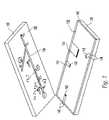
- FIG. 1shows a microfluidic system according to the invention
- FIG. 2shows an expanded view of a microfluidic device.
- FIG. 3shows a schematic of a microfluidic device of the microfluidic system of FIG. 1 ;
- FIG. 4shows a top view of the microfluidic device of FIG. 3 ;
- FIG. 5shows a partial cross-sectional view of the microfluidic device of FIG. 4 ;
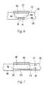
- FIG. 6shows a partial cross-sectional view of an upper substrate from the microfluidic device of FIG. 2 ;
- FIG. 7shows a second partial cross-sectional view of an upper substrate from the microfluidic device of FIG. 2 ;
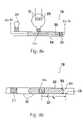
- FIG. 8 ashows a top view of a microdroplet preparation zone of the microfluidic device of FIG. 4 before preparation of a microdroplet;
- FIG. 8 bshows cross sectional view of the microdroplet preparation zone of FIG. 8 a
- FIG. 9 ashows a top view of a microdroplet preparation zone of the microfluidic device of FIG. 4 after preparation of a microdroplet;
- FIG. 9 bshows a cross sectional side view of the microdroplet preparation zone of FIG. 9 a
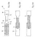
- FIGS. 10 a – 10 cshow cross sectional side views of a capillary assisted fluid barrier of the present invention
- FIGS. 11 a – 11 cshow top views of a fluid barrier comprising a vent
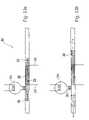
- FIGS. 12 a and 12 bshow top view s of the lysing module of the microfluidic device of FIG. 4 , before and after preparation of a lysed sample;
- FIGS. 13 a and 13 bshow a second embodiment of a lysing module of the invention
- FIG. 14shows a pulsing circuit associated with the lysing module of FIG. 4 ;
- FIGS. 15 a – 15 cshow a second microdroplet preparation module of the invention.
- the present inventionrelates to microfluidic systems and methods for processing materials, such as samples and reagents. More specifically, the invention relates to microfluidic systems and methods for processing particle containing fluids.
- the fluid component of the particle-containing fluidis a gas or, preferably, a liquid. In either case, the fluid entrains particles, which tend to move with the fluid.
- the particles of the particle-containing fluidare preferably whole cells, such as bacterial cells or cells of an animal, such as a human. However, they may include intracellular material from such cells.
- a system of the inventionmay be used to process a sample of bacterial cells to determine whether the bacteria are pathogenic.
- FIG. 1depicts a microfluidic system 100 that includes a microfluidic device 110 and corresponding cartridge 120 , which receive one or more fluid samples and process the samples under the control of computer 127 and data acquisition and control board (DAQ) 126 .
- DAQdata acquisition and control board
- Computer 127preferably performs high level functions, such as supplying a user interface that allows a user to select desired operations, notifying the DAQ 126 as to the selected operations, and displaying for the user the results of such operations. These operations include, for example, subjecting a sample to process steps within the various process zones of the microfluidic device.
- the computer 127may be a portable computer to facilitate transport of the microfluidic system.
- Computer 127is connected to DAQ 126 via connection 128 , which provides data I/O, power, ground, reset, and other functional connectivity.
- a wireless link 132 between the computer 127 and the DAQ 126may be provided for data and control signal exchange via wireless elements 132 ( a ) and 132 ( b ).
- the data linkis a wireless link
- the DAQ 126may have separate power source, such as a battery.
- DAQ 126controls the operation of microfluidic device 110 in accordance with the high level instructions received from computer 127 . More specifically, to implement a desired operation requested by computer 127 , DAQ 126 supplies the appropriate electrical control signals to cartridge 120 via contacts 125 .
- Cartridge 120provides electrical and optical connections 121 for electrical and optical signals between the DAQ 126 and the microfluidic substrate 110 , thereby allowing DAQ 126 to control the operation of the substrate.
- the chip carrier cartridge 120is shown being inserted into (or removed from) an interface hardware receptacle of the DAQ 126 having electrical and optical contacts 125 standardized to mate with corresponding contacts 121 of the chip carrier cartridge 120 .
- Most contactsare for electrical signals, while certain ones are for optical signals (IR, visible, UV, etc.) in the case of optically monitored or optically excited microfluidic processors.
- the entire DAQ 126may be a single ASIC chip that is incorporated into the Chip Carrier Cartridge 120 , wherein contacts 121 , 125 would become conductive pathways on a printed circuit board.
- FIG. 2illustrates the general structure of a preferred type of microfluidic device.
- the deviceincludes an upper substrate 130 , which is bonded to a lower substrate 132 to form a fluid network.
- the upper substrate 130 depicted in FIG. 2is preferably formed of glass and has a microfluidic network 134 in its bottom surface 136 .
- substrates composed of silicon, glass, ceramic, plastic, and/or quartzare all acceptable in the context of the present invention.
- the microfluidic networkincludes a plurality of zones.
- the number of zones, as well as the overall topology of the microfluidic network,will depend upon the particular application which the microfluidic device is designed to perform.
- the zones of the microfluidic devicemay have any cross-sectional shape, such as generally arcuate or generally polygonal.
- a zonemay include channels, chambers or other substantially enclosed spaces.
- substantially enclosedit is meant that materials enter or exit the zones only through predetermined pathways. Examples of such pathways include channels, microchannels and the like, which interconnect the various zones.
- the zonespreferably have at least one micro-scale dimension, such as less than about 250 ⁇ m or, more preferably, less than about 75 ⁇ m.
- the channels and chambers of the microfluidic networkare etched in the bottom surface 136 of the upper substrate 130 using known photolithographic techniques. More specifically, transparent templates or masks containing opaque designs are used to photo-define objects on the surface of the substrate.
- the patterns on the templatesare generated with computer-aided-design programs and can delineate structures with line-widths of less than one micron. Once a template is generated, it can be used almost indefinitely to produce identical replicate structures. Consequently, even extremely complex microfluidic networks can be reproduced in mass quantities and at low incremental unit cost.
- the upper substratemay be formed using injection molding techniques, wherein the micro-channels are formed during the molding process.
- the lower substrate 132may include a glass base 138 and an oxide layer 140 .
- resistive heaters 142 and electric leads 144are formed using photo-lithographic techniques.
- the leads 144connect to terminals 146 which are exposed at the edge of the substrate to permit electrical connection to cartridge 120 , thereby permitting DAQ 126 to control the heaters. More specifically, to activate a heater 142 , DAQ 126 applies a voltage across a pair of terminals 146 (via cartridge 120 ) to supply current through leads 146 and heater 142 , thereby heating the resistive heater element 142 .
- Metal heater elements 142are positioned so that, when the upper and lower substrates are bonded together, the heaters reside directly beneath certain regions of the fluid network of the upper substrate so as to be able to heat the contents of these regions.
- the silicon oxide layer 140prevents the heating elements 142 from directly contacting with material in the microfluidic network.
- the oxide layer 140 , heating elements 142 , and resistive leads 144are fabricated using well-known photolithographic techniques, such as those used to etch the microfluidic network.
- FIG. 3illustrates a top-down view of microfluidic device 110 .
- the substratehas a sample input module 150 and reagent input module 152 to allow sample and reagent materials, respectively, to be input to device 110 .
- input modules 150 , 152are disposed to allow automatic material input using a computer controlled laboratory robot 154 .
- the substratealso includes process modules 156 , 158 , 160 , 166 and 162 for processing the sample and reagent materials.
- a samplemay be subjected to various physical and chemical process steps.
- enrichment module 156prepares a fluid sample having a relatively high concentration of cell particles
- lysing module 160releases intracellular material from the cell particles
- mixing module 166mixes the resultant sample with certain reagents.
- an amplification process module 162may be used to amplify and detect minute quantities of DNA within a sample.
- Various modules of microfluidic device 110are connected, such as by channels 164 , to allow materials to be moved from one location to another within the device 110 .
- Actuators 168 , 170 , 172 associated with the microfluidic deviceprovide a motive force, such as a gas pressure, to move the sample and reagent material along the channels and zones.
- a first actuator 168moves material downstream from process module 156 to process module 158 .
- a second actuator 170moves material downstream to mixing process module 160 .
- actuator 170 or an additional actuatormoves the material to mixing module 166 , where the material mixes with a reagent moved by actuator 172 .
- actuator 172or another actuator, moves the mixed material to module 162 .
- each actuatoris preferably responsible for moving materials within only a subset of the modules of device 110 , sample materials can be controlled more precisely than if a single actuator were responsible for moving material throughout the entire device.
- the various functional elements, of microfluidic device 110are preferably under computer control to allow automatic sample processing and analysis. Actuators 168 , 170 , 172 are connected to contacts 112 .
- a microfluidic device 901includes an enrichment module 156 for concentrating samples received therein. These samples include particle-containing fluids, such as bacterial cell-containing fluids.
- enrichment module 156receives a flow of particle-containing fluid from an input port 180 of input module 150 , and allows the fluid to pass through the zone while accumulating particles within the zone. Thus, as more fluid flows through the zone, the particle concentration increases within the module.
- the resultant concentrated fluid sampleis referred to herein as an enriched particle sample.
- the enrichment moduleincludes an enrichment chamber 931 ( FIG. 5 ), a flow through member 900 , valves 915 , 919 , and sample introduction channel 929 .
- Valve 919is connected between the flow through member 900 and actuator 168 as shown, and valve 915 is connected between the flow through member and a down stream channel 937 which leads to process module 158 .
- These valvesmay be of any type suitable for use in a microfluidic device, such as thermally actuated valves, as discussed in co-pending application Ser. No. 09/953,921, filed Sep. 18, 2001.
- the valvesmaybe reversible between the open and closed states to allow reuse of enrichment module 931 .
- the flow through memberis also connected to the sample input module 150 via the sample introduction channel 929 to allow fluid to flow into the enrichment zone.
- Valve 913is connected to this sample introduction channel to control the in-flow and outflow of fluid from the input port.
- FIG. 5is a cross-sectional view of the enrichment zone which shows the flow through member in greater detail.
- flow through member 900has first and second surfaces 941 , 943 .
- First surface 941is preferably adjacent enrichment chamber 931 .
- Second surface 943is preferably spaced apart from the enrichment chamber 931 by flow through member 900 .
- Flow through member 900is preferably formed of a material having pathways smaller than the diameter of the particles to be enriched, such as pores of less than about 2 microns in diameter, for example, about 0.45 microns.
- Suitable materials for constructing flow through member 900include, for example, filter media such as paper or textiles, polymers having a network of pathways, and glassy materials, such as glass flits.
- FIGS. 6 and 7depict cross sectional views of upper substrate 130 that illustrate an enrichment zone 931 .
- fluidexits enrichment zone 931 through surface 941 , passes through member 900 and enters a space 400 .
- Space 400may include an absorbent material 402 to absorb the exiting fluid.
- space 400preferably provides a substantially self-contained region in which fluid exiting the enrichment zone can collect without contacting exterior portions of the microfluidic system 100 .
- Space 400is formed during the fabrication of upper substrate 130 .
- microfluidic featuressuch as zones and channels, are fabricated at surface 136 of substrate 130 .
- Space 400is fabricated at a surface 137 , which is preferably disposed on the other side of substrate 130 , opposite surface 136 .
- surface 136is mated with lower substrate 132 , fluid can exit enrichment zone 931 via flow through member 900 .
- Flow through member 900 and absorbent material 402do not require adhesives or other fasteners for positioning within substrate 130 . Rather flow through member 900 and absorbent material 402 may be formed of a shape and size that substantially corresponds to space 400 . Friction then holds flow through member 900 and absorbent material 402 in place once they are positioned in space 400 . Any residual gap at locations 404 between flow through member 900 and substrate 130 should be small enough to prevent particles from exiting enrichment zone 931 through the gap 404 . Naturally, adhesive or other fastening means may be used to secure flow through member 900 or absorbent material 402 .
- a flow through memberis formed integrally with a substrate by using microfabrication techniques, such as chemical etching, that introduce pores or other pathways into the substrate.
- the poresprovide fluid passage between enrichment zone 931 and an outer portion of the substrate.
- valves 915 , 919are initially closed, and valve 913 is open.
- a particle-containing fluidis introduced into input port 180 . Since valve 913 is open, it allows the sample to pass along channel 929 into enrichment zone 931 .
- enrichment zone 931can be configured to receive samples directly, such as by injection. Since valves 915 and 919 are closed, fluid is substantially prevented from escaping into actuator 977 and downstream channel 937 .
- flow through member 900provides the only path for fluid to exit the enrichment channel.
- Fluidpasses through surface 941 and exits enrichment zone 931 via second surface 943 , while particles accumulate within the zone.
- Enrichment zone 931can therefore receive a volume of fluid that is larger than the volume of the enrichment chamber 931 .
- the concentration of particles within the chamberincreases relative to the concentration in the particle-containing fluid supplied at the sample input.
- the concentration or number of cells in zone 931preferably becomes great enough to perform a polymerase chain reaction (PCR) analysis of polynucleotides released from the cells in a downstream processing module.
- PCRpolymerase chain reaction
- Enrichment zone 931thus prepares an enriched particle sample from particles of particle-containing fluids received therein.
- the enriched particle samplehas a substantially higher ratio of particles per volume of fluid (PPVF) than the corresponding ratio of the particle-containing fluid received by the enrichment zone.
- the PPVF of the enriched particle sampleis preferably at least about 25 times, preferably about 250 times, more preferably about 1,000 times greater than the PPVF of the particle-containing fluid.
- valve 913is closed thereby blocking further flow of fluid into the enrichment zone, and preventing material in zone 931 from returning to the sample introduction port 180 .
- Valves 915 , 919are then opened, preferably upon actuating heat sources associated therewith. When opened, valve 919 allows actuator 168 to push enriched sample, and valve 915 allows the enriched sample to move downstream.
- Actuator 168provides a motive force that moves the enriched particle sample from enrichment zone 931 .
- Actuator 168is preferably a gas actuator, which provides a gas pressure upon actuation of a heat source 975 , which is in thermal communication with a volume of gas 977 . Actuation of heat source 975 raises the temperature and, therefore the pressure, of gas 977 . The flow through member and the fluid therein substantially prevents gas from escaping the enrichment zone. Thus, the resulting gas pressure moves the enriched particle sample downstream from the enrichment zone 931 .
- the gas actuatormay include elements to facilitate alternative pressure generation techniques such as chemical pressure generation.
- the actuatormay decrease a volume of gas associated with an upstream portion of the enrichment zone to thereby create a pressure differential across the sample that moves the sample from the enrichment zone.
- An example of such an elementis a mechanical actuator, such as a plunger or diagram.
- the gas actuatormay decrease a pressure downstream from the zone relative to a pressure upstream.
- the gas actuatormay include a cooling element in thermal contact with a volume of gas associated with a downstream portion of the zone. Contraction of the gas upon actuating the cooling element creates a gas pressure difference between the upstream and downstream portions of the enrichment zone to move the enriched particle sample from the enrichment zone.
- a mechanical actuatormay be used increase a volume of gas associated with a downstream portion of the enrichment zone to thereby decrease the pressure of the gas and move the enriched particle sample from the enrichment zone.
- the enriched particle sampleis preferably moved downstream with essentially no dilution thereof, i.e., the concentration of the enriched particles is not substantially decreased upon movement from the enrichment zone 931 .
- removal of particles from the enrichment channel of the present inventiondoes not require diluting or otherwise contacting the particles with a fluid different from the fluid of the particle-containing fluid introduced to the enrichment channel.
- removal of the adsorbed substancesrequires an elution fluid, which contacts and thereby dilutes the substances.
- the enriched particle sampleis preferably received by downstream channel 937 .
- Downstream channel 937leads to other processing modules, which perform further processing of the enriched particle sample.
- the enriched particle sampleis received by a microdroplet preparation module 158 , which prepares a microdroplet sample comprising a portion of the enriched particle sample.
- a microdroplet 802is a discrete sample having a predetermined volume between, for example, about 1.0 picoliter and about 0.5 microliters.
- microdroplets prepared by microdroplet preparation moduleprovide a known amount of sample for further processing.
- the volume of the microdroplet prepared by the microdroplet preparation moduleis preferably essentially independent of the viscosity, electrical conductivity, and osmotic strength of the fluid of the microdroplet.
- Microdroplet 802is preferably defined by upstream and downstream boundaries each formed by a respective gas liquid interface 804 , 806 .
- the liquid of the interfaceis formed by a surface of a liquid forming the microdroplet.
- the gas of the interfaceis present in the microfluidic channels of microfluidic device 901 .
- microdroplet preparation module 158prepares a microdroplet 802 from a microfluidic sample received therein.
- This moduleincludes a microdroplet preparation zone 800 , a positioning element 979 , a gas actuator 170 , and a valve 216 which cooperate to prepare microdroplet 800 from microfluidic samples received from the enrichment zone.
- a positioning elementinhibits the downstream progress of a microfluidic sample to thereby position the sample at a desired location.
- the positioning elementdoes not permanently inhibit progress of the sample. Rather, it allows the microfluidic sample to continue downstream at a predetermined later time.
- microfluidic sample 808that reaches positioning element 979 is positioned downstream from an opening 820 of gas actuator 170 . Accordingly, a first portion 821 of microfluidic sample 808 is disposed upstream from opening 820 and a second portion 822 of microfluidic sample 808 is disposed downstream from opening 820 .
- gas actuator 170is actuated, such as by DAQ 126 , to thereby generate a gas pressure sufficient to separate microdroplet 802 from the second portion 822 of microfluidic sample 808 .
- the gas pressureis preferably provided by the actuation of a heat source 958 , which heats a volume of gas associated with gas actuator 170 . As the pressure increases, the gas expands, thereby separating a microdroplet 802 from the rest of sample 808 .
- Microdroplet 802may comprise only a portion, such as less than about 75%, or less than about 50%, of microfluidic sample 808 received by microdroplet preparation zone 800 .
- microdroplet 802are determined by the volume of the channel between fluid barrier 979 and opening 820 .
- a length ii of microdroplet 802corresponds to a distance d 4 between positioning element 979 and opening 820 .
- a microfluidic devicecan be configured to prepare microdroplets of any volume by varying the length between the fluid barrier and corresponding actuator opening.
- gas actuator 170overcomes the inhibitory effect of positioning element 979 , thereby driving microdroplet 802 to a location downstream of microdroplet preparation zone 800 while the second portion 822 of the microfluidics sample moves upstream from microdroplet 802 to cell lysis module 160 .
- a lysing module 160receives the microdroplet 802 prepared by microdroplet preparation zone 800 .
- lysing module 160releases material from inside the particles, such as by releasing intracellular material from cells.
- lysing module 160includes a lysing zone 950 , a lysing mechanism within the lysing zone (such as electrodes 954 ), and a vented positioning element 200 positioned upstream from the lysing zone.
- the lysing mechanismpreferably includes a set of electrodes or other structures for generating electric fields within the lysing zone.
- the vented positioning elementpreferably includes a vent 202 , a valve 204 , and a second positioning element 206 for inhibiting fluid from flowing into the vent.
- actuator 170 of the microdroplet preparation module 158drives a microdroplet into cell lysis module 160 .
- vented positioning element 200positions microdroplet 802 in a lysing position with respect to electrodes 954 . More specifically, as the microdroplet arrives in lysing module 160 it passes the opening of positioning element 200 , because second positioning element 206 inhibits the microdroplet from flowing into vent 202 .
- the propulsion gas from actuator 170dissipates through vent 202 , thereby substantially equalizing gas pressure upstream of microdroplet 802 with a pressure downstream of microdroplet 802 .
- the microdropletstops movement at a lysing position just downstream from barrier 200 .
- substantially all of microdroplet 802is disposed between an upstream edge 212 and a downstream edge 214 of electrodes 954 .
- a pulse circuit of DAQ 126supplies a pulsed voltage signal across electrodes 954 .
- electrodes 954generate a pulsed electric field in the vicinity of the electrodes. Because the microdroplet is position in this vicinity, cells within the microdroplet are subjected to the pulsed field. Preferably, substantially all of the cells, such as greater than about 75%, of the microdroplet are subjected to an electric field sufficient to release intracellular material therefrom.
- the lysing modulethus prepares a lysed microdroplet comprising a predetermined amount of sample.
- a preferred pulse circuitis shown in FIG. 14 .
- this circuitgenerates a sequence of voltage pulses that yields a corresponding sequence of electrical field pulses in the vicinity of electrodes 954 having an amplitude and duration sufficient to release a desired amount of intracellular material from cells within the microdroplet.
- Intracellular material present in lysed microdropletis accessible to further process steps.
- DNA and/or RNA released from cellsis accessible for amplification by a polymerase chain reaction.
- lysingdoes not require that the cells be completely ruptured. Rather, lysing refers to the release of intracellular material.
- the electric fieldmay increase the porosity of cell membranes by an amount that allows release of intracellular material without permanent rupture of the membranes.
- lysing mechanismsmay also be employed to release intracellular material from cells.
- materialmay be released by subjecting cells to other forces including for example osmotic shock or pressure.
- Chemicals, selected from the group of surfactants, solvents, and antibioticsmay be contacted with the cells.
- Mechanical shear methodsmay also be used to release intracellular materials.
- the lysed microdropletmay be moved downstream to mixing module 160 for further processing.
- valve 216which is disposed upstream of lysing zone 950 , is closed.
- Valve 204is also closed to prevent gas from exiting lysing zone 950 via vent.
- Actuator 170is then actuated, as described above, to provide a gas pressure sufficient to move lysed microdroplet downstream of lysing zone 950 .
- a lysing module 300includes a lysing zone 302 which is configured to prepare a lysed microdroplet 304 of predetermined volume from a microfluidic sample 306 , which may have an indeterminate volume.
- Lysing zone 302preferably includes a lysing mechanism such as electrodes 308 .
- Electrical leads 310provide a connection to a pulse circuit of DAQ 126 , via contacts 112 , between microfluidic cartridge 110 and chip carrier 120 , and contacts 125 (as shown in FIGS. 1 and 3 ).
- a positioning element 312is disposed downstream of lysing zone 302 .
- An actuator 314is disposed upstream from lysing zone. Actuator 314 preferably includes a second positioning element 316 to prevent fluid from the microfluidic sample from entering therein.
- Lysing zone 302operates as follows.
- the microfluidic sample 306enters lysing zone 302 and moves downstream until a downstream interface 316 of the microfluidic sample 306 encounters positioning element 312 .
- the positioning element 312preferably increases a surface tension of the downstream interface of the microfluidic sample 306 , thereby inhibiting further downstream movement and positioning a portion of the microfluidic sample in a lysing position with respect to electrodes 308 .
- the lysing positionis defined as the location of the portion of the microfluidic sample disposed downstream of actuator 314 and upstream of positioning element 312 .
- actuator 314 and positioning element 312are disposed adjacent electrodes 308 such that substantially all of the material present in the lysing position is subjected to the electric field upon actuating electrodes 308 .
- Actuation of electrodes 308 in the embodiment described aboveprovides an electrical field sufficient to release intracellular material from cells present in the portion of the microfluidic sample in the lysing position. Once a sufficient amount of intracellular material has been released, actuator 314 is actuated to prepare lysed microdroplet 304 from the microfluidic sample 306 . Actuator 314 preferably provides a gas pressure sufficient to move the lysed microdroplet 304 to a downstream portion of a microfluidic device such as mixing module 166 .
- a lysed sample prepared by lysing module 160is received by mixing module 166 .
- Mixing module 166includes a mixing zone 958 .
- the lysed cell sampleis contacted, such as by mixing, with an amount of reagent received from the reagent source module 152 .
- Reagent source module 152includes a reagent microdroplet preparation zone (RMPZ) 434 , which preferably operates to prepare a microdroplet having a predetermined volume of reagent.
- RMPZreagent microdroplet preparation zone
- Reagent input module 152is essentially the same as microdroplet formation module 158 , however, it is specifically designed for formation of a microdroplet of reagent having a predetermined volume which will yield a desired ratio of reagent to sample when mixed with the microdroplet from cell lysing module 160 .
- Module 152includes an input port 420 , a valve 422 , and an actuator 172 , each of which joins a reagent source channel 428 .
- An overflow channel 424which also joins reagents source channel 428 , may also be provided.
- Actuator 172may include a second positioning element 432 to prevent liquid from entering therein.
- Reagent materialswhich preferably comprise at least one liquid, are introduced via input port 420 , such as with a pipette or syringe.
- suitable reagent materialsinclude substances to facilitate further processing of the lysed cell sample, such as enzymes and other materials for amplifying DNA therein by polymerase chain reaction (PCR).
- the reagent materialmoves downstream within reagent source channel 428 until a downstream portion of the reagent material contacts a positioning element 426 . Any additional reagent material that continues to be received within reagent source module preferably enters overflow channel 424 .
- valve 422is closed to prevent reagent from exiting reagent source channel via reagent source port 420 .
- Mixing zone 958 of the mixing moduleincludes adjoined first and second channels 410 , 412 . Materials moving downstream toward mixing zone 958 contact one another and preferably mix therein. Because of the micro-scale dimensions of mixing zone 958 , the sample and reagent materials preferably mix by diffusion even in the absence of other sources of mass transport, such as mechanical agitation. It should be understood however, that agitation forces, such as acoustic waves may be applied to enhance mixing within mixing zone 958 .
- Reagent source module 152 and mixing module 166preferably operate as follows.
- actuator 172is actuated to prepare a microdroplet of reagent.
- the microdroplet of reagentis prepared from the portion of reagent material downstream of an opening 430 of actuator 172 and upstream of positioning element 427 .
- the volume of the microdroplet of reagentis determined by the distance between the positioning element 426 and the actuator opening 430 .
- the microdroplet of reagentmoves downstream toward channel 412 of reagent mixing zone. Meanwhile, a sample of lysed material, such as a lysed microdroplet, is moved downstream from lysing zone 950 toward channel 410 of mixing zone 958 .
- Actuator 170may provide the motive force to move the lysed microdroplet downstream.
- another actuatormay be disposed upstream of lysing zone 950 but downstream of actuator 170 to provide the necessary motive force.
- the sample and reagent materialenter a downstream channel 438 of mixing zone 958 , where the materials contact and mix. Because both the lysed sample and reagent material are mixed in the form of microdroplets, mixing zone 958 prepares an amount of mixed material having a predetermined ratio of sample to reagent.
- the volumes of microdroplets prepared within microfluidic device 110are preferably independent of physical properties, such as viscosity, electrical conductivity, and osmotic strength, of the microdroplets.
- mixing zone 958prepares an amount of mixed material having a sample to reagent material that is also independent of the physical and chemical properties of the mixed materials.
- a vent 440which is downstream of the various zones of the microfluidic device 110 ensures that downstream pressure buildup does not inhibit downstream movement of samples within microfluidic device 110 .
- DNA manipulation zone 971of DNA manipulation module 162 .
- Module 162can perform, for example, restriction, digestion, ligation, hybridization and amplification of DNA material.
- DNA manipulation zone 971is configured to perform PCR amplification of nucleic acids present within the lysed cell sample.
- Vent 440prevents pressure from increasing within zone 971 as the lysed cell sample and reagent are being introduced thereto.
- Valves 972 and 973 of DNA manipulation module 162may be closed to prevent substances therein zone from exiting, such as by evaporation, during PCR amplification.
- the DNA manipulation zoneis configured with heat sources under control of computer 127 to allow thermal cycling of DNA manipulation zone during amplification, as understood by one of skill in the art.
- System 901includes also includes a detector 981 to detect the presence of amplified polynucleotides produced by PCR.
- Detector 981is preferably an optical detector in optical communication, such as by a fiber optic 981 , with zone 971 .
- a light sourcesuch as a laser diode, introduces light to DNA Manipulation zone 971 to generate fluorescence indicative of the amount of amplified polynucleotides present therein. The fluorescence arises from fluorescent tags, included in the reagent and associated with the polynucleotides upon amplification.
- a positioning element 979may be formed by a non-wetting material disposed to contact a microfluidic sample.
- the physico-chemical properties of the non-wetting materialare chosen upon considering the type of liquid forming the microfluidic sample.
- the positioning elementpreferably comprises a hydrophobic material.
- An exemplary hydrophobic materialincludes a non-polar organic compound, such as an aliphatic silane, which can be formed by modifying an internal surface of microfluidic device 901 .
- the non-wetting materialmay comprise a hydrophilic material.
- microfluidic sample 808encounters positioning element 979 , the liquid of the microfluidic sample experiences an increased surface tension at downstream interface 810 , which increased surface tension inhibits continued downstream motion of microfluidic sample 808 .
- Increasing the gas pressure difference between upstream and downstream portions of the microfluidic sampleovercomes the resistance and moves the microfluidic sample downstream.
- a CAFBcomprises an upstream feed zone 702 , a loading zone 704 , and a stop zone 706 .
- a microfluidic sample 720 encountering the CAFBmoves downstream until a downstream interface 710 of the microfluidic sample contacts upstream surfaces 712 of the loading zone 704 .
- capillary actioncauses the microfluidic sample to move downstream until the downstream sample interface 710 encounters the opening 714 between the loading zone 704 and the stop zone 706 .
- Surface tensionresists the tendency of the microfluidic sample to continue downstream past opening 714 .
- the microfluidic sample 720is positioned at a predetermined location along the channel axis with respect to positioning element 700 .
- the volume of the microfluidic sample encountering the CAFBpreferably has a larger volume than a volume of the loading zone 704 to ensure that the microfluidic sample will advance fully to opening.
- the depth d 1 of the loading zone 704is preferably about 50% or less of the respective depths d 2 , d 3 of the feed and stop zones.
- a MRC r 1 of a microdroplet interface in the loading zoneis preferably smaller than a MRC r 2 of a droplet interface within the feed zone or a MRC r 3 of a droplet interface within the stop zone.
- the MRC r 2is preferably larger than the MRC r 3 .
- the contact angle of the fluid with the wallis substantially constant throughout the capillary assisted loading zone.
- a positioning element 500operates to position a microfluidic sample 502 by reducing the gas pressure acting upon an upstream portion 504 of the microfluidic sample relative to the gas pressure acting upon a downstream portion 506 of the microfluidic sample.
- Positioning element 500includes a vent 508 disposed in gaseous communication with a zone 510 along which microfluidic sample 502 moves. Vent 508 preferably communicates with zone 510 via a passage 526 .
- the zonemay be for example, a channel or conduit.
- Positioning element 500may also include a second positioning element 516 , such as a non-wetting material, to substantially prevent fluid from the microfluidic sample from contacting the vent.
- Valve 512is preferably thermally actuated and includes a mass 514 of thermally responsive substance (TRS).
- TRSthermally responsive substance
- An actuator 518is disposed upstream of positioning element 500 .
- Actuator 518is preferably a gas actuator and may include a heat source 520 to heat a gas associated with actuator 518 .
- Actuator 518may include a positioning element 522 , such as non-wetting material, to substantially prevent fluid from the microfluidic sample from entering therein.
- Positioning element 500preferably operates as follows. Referring to FIG. 11 a , microfluidic sample 502 moves downstream in the direction of arrow 524 . Microfluidic sample is preferably moved by a gas pressure provided from an upstream actuator, which is not shown in FIGS. 11 a – 11 c . The gas pressure acts upon upstream portion 504 .
- upstream portion 504passes the opening of vent 508 , the upstream gas dissipates through vent 508 , thereby reducing the upstream pressure.
- the pressure reductionwhich preferably equalizes the downstream and upstream pressures, reduces or eliminates the motive force tending to urge the microfluidic sample downstream.
- valve 512is closed to prevent passage of gas between zone 510 and vent 508 .
- TRS 514moves into passage 526 .
- the actuation of actuator 518provides a motive force to move microfluidic sample 502 downstream in the direction of arrow 528 for further processing.
- a microdroplet preparation module 652has a microdroplet preparation zone 650 , an active fluid positioning element 654 , an actuator 656 , and a valve 658 .
- a second actuator 660is operatively associated with the active positioning element 654 to introduce a microfluidic sample 666 to the microdroplet preparation zone 650 .
- Second actuator 660is preferably located upstream from valve 658 .
- Microdroplet preparation module 652prepares a microdroplet 668 , which has a predetermined volume from the microfluidic sample 666 received therein.
- microfluidic preparation module 652receives the microfluidic sample 666 , which moves downstream because of a motive force provided by the second actuator 660 .
- the motive forceis preferably an upstream gas pressure, which is greater than a downstream gas pressure acting upon the microfluidic sample 666 .
- the microfluidic samplemoves downstream until a downstream portion 670 thereof encounters active positioning element 654 , which preferably comprises a sensor 672 having electrical leads 674 .
- the leads 674are in electrical communication with I/O pins of the microfluidic device to allow signals from sensor 672 to be received by a DAQ.
- Sensing element 672is preferably a pair of electrical contacts. To sense the presence of the liquid, DAQ 126 applies a small voltage across leads 674 and measures the resultant current. As the liquid of the microfluidic sample contacts the first and second contacts, the current passing therebetween changes, thereby indicating to DAQ 126 that the liquid has arrived at sensor 672 .
- the DAQinstructs second actuator 660 to decrease a downstream motive force acting upon the microfluidic sample 666 .
- DAQmay reduce a current flowing through a heat source 676 associated with second actuator 660 thereby reducing a temperature of a gas therein. The temperature reduction reduces the gas pressure acting upon a upstream portion 678 of microfluidic sample thereby inhibiting the downstream motion of the microfluidic sample 666 .
- the microfluidic sampleis positioned such that a first portion 680 is located downstream of actuator 656 and a second portion 682 is located upstream of actuator 656 .
- DAQ 126actuates actuator 656 to provide a motive force which prepares the microdroplet 668 from the first portion 680 of microfluidic sample 666 .
- Microdroplet 668moves downstream while the second portion 682 of the microfluidic sample 666 moves upstream from actuator 656 .
- valve 658may be closed to substantially isolate the actuator 656 from second actuator 660 and other upstream portions of the microfluidic device.
- the active positioning elementpreferably operates as a closed loop element that provides feedback from sensor 672 to the DAQ.
- the feedbackis indicated when a microfluidic sample has reached a predetermined position within the microfluidic device.
- the DAQchanges the state of the actuator providing the motive force to move the microdroplet.
- the various actuators of microfluidic device 110provide an example of how multiple actuators may cooperate to move material between different locations of microfluidic device 110 .
- actuator 168moves material, such as an enriched sample, between enrichment zone 931 and microdroplet preparation module 158 .
- Actuator 170prepares a microdroplet from the enriched sample and, in so doing, moves the microdroplet to the lysing zone 950 .
- Actuator 170is used to move material from the lysing zone 950 to mixing module 166 . It should be noted, however, that another actuator may be disposed intermediate between lysing zone 950 and microdroplet preparation zone to move the lysed sample downstream to the mixing module 166 .
- Actuators of device 110may also cooperate in moving two amounts of material simultaneously.
- actuator 172 and actuator 170cooperate to mix reagent and lysed microdroplets.
- Such cooperative actuatorscan be controlled independently of one another to ensure proper mixing. For example, if one material is known to be more viscous, the motive force moving that material can be increased independently of the motive force moving the other material.
- the multiple actuators and modules of microfluidic device 110are preferably operatively connectable and isolatable by the valves of microfluidic device. For example, a closed state of either of valves 915 , 216 operatively isolates microdroplet preparation module 170 from enrichment module 156 .
- one or more actuatorscan be used to move materials between predetermined locations within microfluidic device 110 , without perturbing or contacting material present in an operatively isolated module.
- the ability to operatively connect and isolate desired modulesis advantageous in microfluidic devices having many process functions.
- these valvesalso control the direction of the propulsive force of the actuators by preventing the expanding gas from traveling in certain directions, while permitting it to expand in the desired direction. This also extends the range over which an actuator can propel a microdroplet, by preventing the gas from dissipating in certain areas upstream from the microdroplet.
Landscapes
- Chemical & Material Sciences (AREA)
- Health & Medical Sciences (AREA)
- Engineering & Computer Science (AREA)
- Analytical Chemistry (AREA)
- General Health & Medical Sciences (AREA)
- Dispersion Chemistry (AREA)
- Hematology (AREA)
- Clinical Laboratory Science (AREA)
- Chemical Kinetics & Catalysis (AREA)
- Mechanical Engineering (AREA)
- General Engineering & Computer Science (AREA)
- Physics & Mathematics (AREA)
- Life Sciences & Earth Sciences (AREA)
- Biochemistry (AREA)
- General Physics & Mathematics (AREA)
- Immunology (AREA)
- Pathology (AREA)
- Apparatus Associated With Microorganisms And Enzymes (AREA)
Abstract
Description
Claims (31)
Priority Applications (10)
| Application Number | Priority Date | Filing Date | Title |
|---|---|---|---|
| US10/014,519US7192557B2 (en) | 2001-03-28 | 2001-12-14 | Methods and systems for releasing intracellular material from cells within microfluidic samples of fluids |
| US10/075,371US7323140B2 (en) | 2001-03-28 | 2002-02-15 | Moving microdroplets in a microfluidic device |
| ES02715213.1TES2683698T3 (en) | 2001-07-26 | 2002-03-27 | Methods and systems for microfluidic processing |
| JP2003517550AJP4596776B2 (en) | 2001-07-26 | 2002-03-27 | Microfluidic processing method and system |
| PCT/US2002/009440WO2003012406A1 (en) | 2001-07-26 | 2002-03-27 | Methods and systems for microfluidic processing |
| EP18185265.8AEP3427834A1 (en) | 2001-07-26 | 2002-03-27 | Methods and systems for microfluidic processing |
| EP02715213.1AEP1438567B1 (en) | 2001-07-26 | 2002-03-27 | Methods and systems for microfluidic processing |
| US11/929,971US8273308B2 (en) | 2001-03-28 | 2007-10-30 | Moving microdroplets in a microfluidic device |
| US13/620,452US8703069B2 (en) | 2001-03-28 | 2012-09-14 | Moving microdroplets in a microfluidic device |
| US14/255,861US20140227710A1 (en) | 2001-03-28 | 2014-04-17 | Moving microdroplets in a microfluidic device |
Applications Claiming Priority (4)
| Application Number | Priority Date | Filing Date | Title |
|---|---|---|---|
| US09/819,105US7010391B2 (en) | 2001-03-28 | 2001-03-28 | Methods and systems for control of microfluidic devices |
| US30763801P | 2001-07-26 | 2001-07-26 | |
| US09/953,921US6575188B2 (en) | 2001-07-26 | 2001-09-18 | Methods and systems for fluid control in microfluidic devices |
| US10/014,519US7192557B2 (en) | 2001-03-28 | 2001-12-14 | Methods and systems for releasing intracellular material from cells within microfluidic samples of fluids |
Related Parent Applications (2)
| Application Number | Title | Priority Date | Filing Date |
|---|---|---|---|
| US09/819,105Continuation-In-PartUS7010391B2 (en) | 2001-03-28 | 2001-03-28 | Methods and systems for control of microfluidic devices |
| US09/953,921Continuation-In-PartUS6575188B2 (en) | 2001-03-28 | 2001-09-18 | Methods and systems for fluid control in microfluidic devices |
Related Child Applications (1)
| Application Number | Title | Priority Date | Filing Date |
|---|---|---|---|
| US10/075,371Continuation-In-PartUS7323140B2 (en) | 2001-03-28 | 2002-02-15 | Moving microdroplets in a microfluidic device |
Publications (2)
| Publication Number | Publication Date |
|---|---|
| US20020142482A1 US20020142482A1 (en) | 2002-10-03 |
| US7192557B2true US7192557B2 (en) | 2007-03-20 |
Family
ID=27486402
Family Applications (1)
| Application Number | Title | Priority Date | Filing Date |
|---|---|---|---|
| US10/014,519Expired - LifetimeUS7192557B2 (en) | 2001-03-28 | 2001-12-14 | Methods and systems for releasing intracellular material from cells within microfluidic samples of fluids |
Country Status (1)
| Country | Link |
|---|---|
| US (1) | US7192557B2 (en) |
Cited By (81)
| Publication number | Priority date | Publication date | Assignee | Title |
|---|---|---|---|---|
| US20040115097A1 (en)* | 2001-04-09 | 2004-06-17 | Achim Wixforth | Mixing deivce and mixing method for mixing small amounts of liquid |
| WO2005011867A2 (en) | 2003-07-31 | 2005-02-10 | Handylab, Inc. | Processing particle-containing samples |
| US20050084424A1 (en)* | 2001-03-28 | 2005-04-21 | Karthik Ganesan | Systems and methods for thermal actuation of microfluidic devices |
| US20060043284A1 (en)* | 2002-11-29 | 2006-03-02 | Nec Corporation | Micro chip, liquid feeding method using the micro chip, and mass analyzing system |
| US20060166226A1 (en)* | 2005-01-21 | 2006-07-27 | Thermogen Inc. | DNA amplification device |
| US20070137062A1 (en)* | 2005-07-05 | 2007-06-21 | Eck Gary A | Increased Negative Static Pressure Drying |
| US20080050804A1 (en)* | 2001-03-28 | 2008-02-28 | Kalyan Handique | Moving microdroplets in a microfluidic device |
| US20090136386A1 (en)* | 2007-07-13 | 2009-05-28 | Handylab, Inc. | Rack for Sample Tubes and Reagent Holders |
| US20100021910A1 (en)* | 2008-07-18 | 2010-01-28 | Canon U.S. Life Sciences, Inc. | Methods and Systems for Microfluidic DNA Sample Preparation |
| USRE41780E1 (en) | 2003-03-14 | 2010-09-28 | Lawrence Livermore National Security, Llc | Chemical amplification based on fluid partitioning in an immiscible liquid |
| US20110014605A1 (en)* | 2009-07-17 | 2011-01-20 | Canon U.S. Life Sciences, Inc. | Methods and systems for dna isolation on a microfluidic device |
| US20110027151A1 (en)* | 2007-07-13 | 2011-02-03 | Handylab, Inc. | Reagent tube |
| US20110053798A1 (en)* | 2009-09-02 | 2011-03-03 | Quantalife, Inc. | System for mixing fluids by coalescence of multiple emulsions |
| US20110086780A1 (en)* | 2008-09-23 | 2011-04-14 | Quantalife, Inc. | System for forming an array of emulsions |
| US20110212516A1 (en)* | 2008-09-23 | 2011-09-01 | Ness Kevin D | Flow-based thermocycling system with thermoelectric cooler |
| US20110217712A1 (en)* | 2010-03-02 | 2011-09-08 | Quantalife, Inc. | Emulsion chemistry for encapsulated droplets |
| US8043581B2 (en) | 2001-09-12 | 2011-10-25 | Handylab, Inc. | Microfluidic devices having a reduced number of input and output connections |
| US8088616B2 (en) | 2006-03-24 | 2012-01-03 | Handylab, Inc. | Heater unit for microfluidic diagnostic system |
| US8105783B2 (en) | 2007-07-13 | 2012-01-31 | Handylab, Inc. | Microfluidic cartridge |
| US8133671B2 (en) | 2007-07-13 | 2012-03-13 | Handylab, Inc. | Integrated apparatus for performing nucleic acid extraction and diagnostic testing on multiple biological samples |
| USD665095S1 (en) | 2008-07-11 | 2012-08-07 | Handylab, Inc. | Reagent holder |
| USD669191S1 (en) | 2008-07-14 | 2012-10-16 | Handylab, Inc. | Microfluidic cartridge |
| US8287820B2 (en) | 2007-07-13 | 2012-10-16 | Handylab, Inc. | Automated pipetting apparatus having a combined liquid pump and pipette head system |
| US8323900B2 (en) | 2006-03-24 | 2012-12-04 | Handylab, Inc. | Microfluidic system for amplifying and detecting polynucleotides in parallel |
| US8324372B2 (en) | 2007-07-13 | 2012-12-04 | Handylab, Inc. | Polynucleotide capture materials, and methods of using same |
| US8440149B2 (en) | 2001-02-14 | 2013-05-14 | Handylab, Inc. | Heat-reduction methods and systems related to microfluidic devices |
| US8470586B2 (en) | 2004-05-03 | 2013-06-25 | Handylab, Inc. | Processing polynucleotide-containing samples |
| USD692162S1 (en) | 2011-09-30 | 2013-10-22 | Becton, Dickinson And Company | Single piece reagent holder |
| US8617905B2 (en) | 1995-09-15 | 2013-12-31 | The Regents Of The University Of Michigan | Thermal microvalves |
| US8663920B2 (en) | 2011-07-29 | 2014-03-04 | Bio-Rad Laboratories, Inc. | Library characterization by digital assay |
| US8709787B2 (en) | 2006-11-14 | 2014-04-29 | Handylab, Inc. | Microfluidic cartridge and method of using same |
| US8709762B2 (en) | 2010-03-02 | 2014-04-29 | Bio-Rad Laboratories, Inc. | System for hot-start amplification via a multiple emulsion |
| US8730479B2 (en) | 2010-03-25 | 2014-05-20 | Bio-Rad Laboratories, Inc. | Detection system for droplet-based assays |
| US8852862B2 (en) | 2004-05-03 | 2014-10-07 | Handylab, Inc. | Method for processing polynucleotide-containing samples |
| US8883490B2 (en) | 2006-03-24 | 2014-11-11 | Handylab, Inc. | Fluorescence detector for microfluidic diagnostic system |
| US8895311B1 (en) | 2001-03-28 | 2014-11-25 | Handylab, Inc. | Methods and systems for control of general purpose microfluidic devices |
| US8951939B2 (en) | 2011-07-12 | 2015-02-10 | Bio-Rad Laboratories, Inc. | Digital assays with multiplexed detection of two or more targets in the same optical channel |
| US9040288B2 (en) | 2006-03-24 | 2015-05-26 | Handylab, Inc. | Integrated system for processing microfluidic samples, and method of using the same |
| US9050594B2 (en) | 2012-02-13 | 2015-06-09 | Neumodx Molecular, Inc. | System and method for processing and detecting nucleic acids |
| US9089844B2 (en) | 2010-11-01 | 2015-07-28 | Bio-Rad Laboratories, Inc. | System for forming emulsions |
| US9132394B2 (en) | 2008-09-23 | 2015-09-15 | Bio-Rad Laboratories, Inc. | System for detection of spaced droplets |
| US9186677B2 (en) | 2007-07-13 | 2015-11-17 | Handylab, Inc. | Integrated apparatus for performing nucleic acid extraction and diagnostic testing on multiple biological samples |
| US9222623B2 (en) | 2013-03-15 | 2015-12-29 | Genmark Diagnostics, Inc. | Devices and methods for manipulating deformable fluid vessels |
| US9222954B2 (en) | 2011-09-30 | 2015-12-29 | Becton, Dickinson And Company | Unitized reagent strip |
| US9222128B2 (en) | 2011-03-18 | 2015-12-29 | Bio-Rad Laboratories, Inc. | Multiplexed digital assays with combinatorial use of signals |
| US9259735B2 (en) | 2001-03-28 | 2016-02-16 | Handylab, Inc. | Methods and systems for control of microfluidic devices |
| US20160077031A1 (en)* | 2014-09-15 | 2016-03-17 | Sensirion Ag | Integrated chemical sensor chip |
| US9347059B2 (en) | 2011-04-25 | 2016-05-24 | Bio-Rad Laboratories, Inc. | Methods and compositions for nucleic acid analysis |
| US9382532B2 (en) | 2012-10-25 | 2016-07-05 | Neumodx Molecular, Inc. | Method and materials for isolation of nucleic acid materials |
| US9393560B2 (en) | 2010-03-25 | 2016-07-19 | Bio-Rad Laboratories, Inc. | Droplet transport system for detection |
| US9399215B2 (en) | 2012-04-13 | 2016-07-26 | Bio-Rad Laboratories, Inc. | Sample holder with a well having a wicking promoter |
| US9417190B2 (en) | 2008-09-23 | 2016-08-16 | Bio-Rad Laboratories, Inc. | Calibrations and controls for droplet-based assays |
| US9492797B2 (en) | 2008-09-23 | 2016-11-15 | Bio-Rad Laboratories, Inc. | System for detection of spaced droplets |
| US9500664B2 (en) | 2010-03-25 | 2016-11-22 | Bio-Rad Laboratories, Inc. | Droplet generation for droplet-based assays |
| US9498778B2 (en) | 2014-11-11 | 2016-11-22 | Genmark Diagnostics, Inc. | Instrument for processing cartridge for performing assays in a closed sample preparation and reaction system |
| US9598722B2 (en) | 2014-11-11 | 2017-03-21 | Genmark Diagnostics, Inc. | Cartridge for performing assays in a closed sample preparation and reaction system |
| US9604213B2 (en) | 2012-02-13 | 2017-03-28 | Neumodx Molecular, Inc. | System and method for processing and detecting nucleic acids |
| US9618139B2 (en) | 2007-07-13 | 2017-04-11 | Handylab, Inc. | Integrated heater and magnetic separator |
| USD787087S1 (en) | 2008-07-14 | 2017-05-16 | Handylab, Inc. | Housing |
| US9764322B2 (en) | 2008-09-23 | 2017-09-19 | Bio-Rad Laboratories, Inc. | System for generating droplets with pressure monitoring |
| US9765389B2 (en) | 2011-04-15 | 2017-09-19 | Becton, Dickinson And Company | Scanning real-time microfluidic thermocycler and methods for synchronized thermocycling and scanning optical detection |
| US9957553B2 (en) | 2012-10-24 | 2018-05-01 | Genmark Diagnostics, Inc. | Integrated multiplex target analysis |
| US10005080B2 (en) | 2014-11-11 | 2018-06-26 | Genmark Diagnostics, Inc. | Instrument and cartridge for performing assays in a closed sample preparation and reaction system employing electrowetting fluid manipulation |
| US20180221878A1 (en)* | 2015-10-09 | 2018-08-09 | Sysmex Corporation | Specimen treatment chip, specimen treatment apparatus, and specimen treatment method |
| US10093963B2 (en) | 2012-02-13 | 2018-10-09 | Neumodx Molecular, Inc. | System and method for processing biological samples |
| US10495656B2 (en) | 2012-10-24 | 2019-12-03 | Genmark Diagnostics, Inc. | Integrated multiplex target analysis |
| US10512910B2 (en) | 2008-09-23 | 2019-12-24 | Bio-Rad Laboratories, Inc. | Droplet-based analysis method |
| USD881409S1 (en) | 2013-10-24 | 2020-04-14 | Genmark Diagnostics, Inc. | Biochip cartridge |
| US10822644B2 (en) | 2012-02-03 | 2020-11-03 | Becton, Dickinson And Company | External files for distribution of molecular diagnostic tests and determination of compatibility between tests |
| US10900066B2 (en) | 2006-03-24 | 2021-01-26 | Handylab, Inc. | Microfluidic system for amplifying and detecting polynucleotides in parallel |
| US20210123936A1 (en)* | 2018-07-10 | 2021-04-29 | Precision Planting Llc | Agricultural sampling system and related methods |
| US11130128B2 (en) | 2008-09-23 | 2021-09-28 | Bio-Rad Laboratories, Inc. | Detection method for a target nucleic acid |
| US11426727B2 (en) | 2020-04-28 | 2022-08-30 | Siemens Healthcare Diagnostics Inc. | Acoustophoretic lysis devices and methods |
| US11453906B2 (en) | 2011-11-04 | 2022-09-27 | Handylab, Inc. | Multiplexed diagnostic detection apparatus and methods |
| US11485968B2 (en) | 2012-02-13 | 2022-11-01 | Neumodx Molecular, Inc. | Microfluidic cartridge for processing and detecting nucleic acids |
| US11648561B2 (en) | 2012-02-13 | 2023-05-16 | Neumodx Molecular, Inc. | System and method for processing and detecting nucleic acids |
| US11806718B2 (en) | 2006-03-24 | 2023-11-07 | Handylab, Inc. | Fluorescence detector for microfluidic diagnostic system |
| US12090480B2 (en) | 2008-09-23 | 2024-09-17 | Bio-Rad Laboratories, Inc. | Partition-based method of analysis |
| US12097495B2 (en) | 2011-02-18 | 2024-09-24 | Bio-Rad Laboratories, Inc. | Methods and compositions for detecting genetic material |
| US12162008B2 (en) | 2008-09-23 | 2024-12-10 | Bio-Rad Laboratories, Inc. | Partition-based method of analysis |
| US12168231B2 (en) | 2008-09-23 | 2024-12-17 | Bio-Rad Laboratories, Inc. | Method of analysis |
Families Citing this family (30)
| Publication number | Priority date | Publication date | Assignee | Title |
|---|---|---|---|---|
| US20030138819A1 (en)* | 2001-10-26 | 2003-07-24 | Haiqing Gong | Method for detecting disease |
| US7338760B2 (en)* | 2001-10-26 | 2008-03-04 | Ntu Ventures Private Limited | Sample preparation integrated chip |
| US20040086872A1 (en)* | 2002-10-31 | 2004-05-06 | Childers Winthrop D. | Microfluidic system for analysis of nucleic acids |
| US20040157220A1 (en)* | 2003-02-10 | 2004-08-12 | Purnima Kurnool | Methods and apparatus for sample tracking |
| WO2004091763A2 (en) | 2003-04-10 | 2004-10-28 | President And Fellows Of Harvard College | Formation and control of fluidic species |
| US7357898B2 (en)* | 2003-07-31 | 2008-04-15 | Agency For Science, Technology And Research | Microfluidics packages and methods of using same |
| BRPI0414004A (en) | 2003-08-27 | 2006-10-24 | Harvard College | electronic control of fluidic species |
| JP2008512128A (en)* | 2004-09-09 | 2008-04-24 | マイクロフルイディク システムズ インコーポレイテッド | Extraction apparatus and sample preparation method |
| US8053214B2 (en)* | 2004-09-09 | 2011-11-08 | Microfluidic Systems, Inc. | Apparatus and method of extracting and optically analyzing an analyte from a fluid-based sample |
| KR100612877B1 (en)* | 2004-12-01 | 2006-08-14 | 삼성전자주식회사 | Novel heating material, method and apparatus for lysing cells using the heating material |
| US7785868B2 (en)* | 2004-12-02 | 2010-08-31 | Microfluidic Systems, Inc. | Apparatus to automatically lyse a sample |
| KR100601982B1 (en)* | 2005-01-20 | 2006-07-18 | 삼성전자주식회사 | Cell lysis method by heat-cooling process through endothermic reaction |
| PL1883474T3 (en) | 2005-05-25 | 2021-10-18 | Boehringer Ingelheim Vetmedica Gmbh | System for the integrated and automated analysis of dna or protein and method for operating said type of system |
| US10816563B2 (en) | 2005-05-25 | 2020-10-27 | Boehringer Ingelheim Vetmedica Gmbh | System for operating a system for the integrated and automated analysis of DNA or protein |
| US7618588B2 (en)* | 2005-08-10 | 2009-11-17 | Microfluidic Systems, Inc. | Disposable integrated heater and tube assembly for thermally-driven chemical reactions |
| US7858366B2 (en)* | 2006-08-24 | 2010-12-28 | Microfluidic Systems, Inc | Integrated airborne substance collection and detection system |
| US20080050724A1 (en)* | 2006-08-24 | 2008-02-28 | Microfluidic Systems, Inc. | Method of detecting one or more limited copy targets |
| US7633606B2 (en)* | 2006-08-24 | 2009-12-15 | Microfluidic Systems, Inc. | Integrated airborne substance collection and detection system |
| US7705739B2 (en)* | 2006-08-24 | 2010-04-27 | Microfluidic Systems, Inc. | Integrated airborne substance collection and detection system |
| US20100104485A1 (en)* | 2008-10-28 | 2010-04-29 | Microfluidic Systems, Inc. | Flow-through thermal cycling device |
| WO2012072822A1 (en) | 2010-12-03 | 2012-06-07 | Mindseeds Laboratories Srl | Microanalysis of cellular function |
| EP2646830B1 (en) | 2010-12-03 | 2016-04-13 | Cellply S.R.L. | Rapid screening of monoclonal antibodies |
| KR20140122751A (en) | 2012-02-08 | 2014-10-20 | 프레지던트 앤드 펠로우즈 오브 하바드 칼리지 | Droplet formation using fluid breakup |
| CN105170207B (en)* | 2015-09-29 | 2017-06-16 | 北京工业大学 | A kind of microlayer model control chip based on branch structure |
| KR20190023067A (en) | 2016-06-14 | 2019-03-07 | 첼플리 에스.알.엘. | Screening kit and method |
| WO2018065110A1 (en) | 2016-10-07 | 2018-04-12 | Boehringer Ingelheim Vetmedica Gmbh | Analysis device and method for testing a sample |
| US10953403B2 (en) | 2016-10-07 | 2021-03-23 | Boehringer Ingelheim Vetmedica Gmbh | Method and analysis system for testing a sample |
| CN108707536A (en)* | 2018-04-10 | 2018-10-26 | 广东顺德墨赛生物科技有限公司 | Drop formation method and system |
| CA3122712A1 (en)* | 2018-12-10 | 2020-06-18 | Combinati Incorporated | Microfluidic array for sample digitization |
| CN115788818B (en)* | 2023-02-08 | 2023-06-16 | 中国科学技术大学 | Liquid metal driving device |
Citations (137)
| Publication number | Priority date | Publication date | Assignee | Title |
|---|---|---|---|---|
| US1616419A (en) | 1925-04-03 | 1927-02-01 | Everlasting Valve Co | Automatic shut-off device for gas in case of fire |
| US1773401A (en) | 1927-10-20 | 1930-08-19 | Luther D Lovekin | Fusible-plug water release |
| US3528449A (en) | 1968-02-27 | 1970-09-15 | Trw Inc | Fluid flow control apparatus |
| US4139005A (en) | 1977-09-01 | 1979-02-13 | Dickey Gilbert C | Safety release pipe cap |
| US4612959A (en) | 1985-05-07 | 1986-09-23 | Mobil Oil Corporation | Valveless shut-off and transfer device |
| US4654127A (en) | 1984-04-11 | 1987-03-31 | Sentech Medical Corporation | Self-calibrating single-use sensing device for clinical chemistry and method of use |
| US4673657A (en) | 1983-08-26 | 1987-06-16 | The Regents Of The University Of California | Multiple assay card and system |
| US4946562A (en) | 1987-01-29 | 1990-08-07 | Medtest Systems, Inc. | Apparatus and methods for sensing fluid components |
| US4949742A (en) | 1989-04-26 | 1990-08-21 | Spectra-Physics, Inc. | Temperature operated gas valve |
| US4963498A (en) | 1985-08-05 | 1990-10-16 | Biotrack | Capillary flow device |
| US4989626A (en) | 1988-11-11 | 1991-02-05 | Hitachi, Ltd. | Apparatus for and method of controlling the opening and closing of channel for liquid |
| US5001417A (en) | 1987-06-01 | 1991-03-19 | Abbott Laboratories | Apparatus for measuring electrolytes utilizing optical signals related to the concentration of the electrolytes |
| US5004583A (en) | 1987-01-29 | 1991-04-02 | Medtest Systems, Inc. | Universal sensor cartridge for use with a universal analyzer for sensing components in a multicomponent fluid |
| US5053199A (en) | 1989-02-21 | 1991-10-01 | Boehringer Mannheim Corporation | Electronically readable information carrier |
| US5061336A (en) | 1989-05-01 | 1991-10-29 | Soane Technologies, Inc. | Gel casting method and apparatus |
| US5064618A (en) | 1987-08-29 | 1991-11-12 | Thorn Emi Plc | Sensor arrangements |
| US5071531A (en) | 1989-05-01 | 1991-12-10 | Soane Technologies, Inc. | Casting of gradient gels |
| US5126002A (en) | 1989-09-29 | 1992-06-30 | Glory Kogyo Kabushiki Kaisha | Leaf paper bundling apparatus |
| US5126022A (en) | 1990-02-28 | 1992-06-30 | Soane Tecnologies, Inc. | Method and device for moving molecules by the application of a plurality of electrical fields |
| US5135627A (en) | 1990-10-15 | 1992-08-04 | Soane Technologies, Inc. | Mosaic microcolumns, slabs, and separation media for electrophoresis and chromatography |
| US5135872A (en) | 1989-04-28 | 1992-08-04 | Sangstat Medical Corporation | Matrix controlled method of delayed fluid delivery for assays |
| US5147606A (en) | 1990-08-06 | 1992-09-15 | Miles Inc. | Self-metering fluid analysis device |
| US5208163A (en) | 1990-08-06 | 1993-05-04 | Miles Inc. | Self-metering fluid analysis device |
| US5250263A (en) | 1990-11-01 | 1993-10-05 | Ciba-Geigy Corporation | Apparatus for processing or preparing liquid samples for chemical analysis |
| US5282950A (en) | 1991-07-15 | 1994-02-01 | Boehringer Mannheim Gmbh | Electrochemical analysis system |
| US5296375A (en) | 1992-05-01 | 1994-03-22 | Trustees Of The University Of Pennsylvania | Mesoscale sperm handling devices |
| US5304487A (en) | 1992-05-01 | 1994-04-19 | Trustees Of The University Of Pennsylvania | Fluid handling in mesoscale analytical devices |
| US5304477A (en) | 1991-07-08 | 1994-04-19 | Fuji Oil Company, Limited | Process for producing hard fats using 1,3-specific lipase and mixture of palmitic, lauric and behemic acids |
| US5311896A (en) | 1989-04-10 | 1994-05-17 | Niilo Kaartinen | Method for producing a heatable and refrigerable element for a system handling small quantities of liquid, and an element manufactured by the method |
| US5316727A (en) | 1989-09-08 | 1994-05-31 | Terumo Kabushiki Kaisha | Measuring apparatus |
| US5339486A (en) | 1993-03-10 | 1994-08-23 | Persic Jr William V | Golf ball cleaner |
| US5372946A (en) | 1992-12-10 | 1994-12-13 | International Technidyne Corporation | Blood coagulation time test apparatus and method |
| US5374395A (en) | 1993-10-14 | 1994-12-20 | Amoco Corporation | Diagnostics instrument |
| US5411708A (en) | 1991-08-06 | 1995-05-02 | Moscetta; Pompeo | Apparatus for the determination of analytes in liquid samples |
| US5486335A (en) | 1992-05-01 | 1996-01-23 | Trustees Of The University Of Pennsylvania | Analysis based on flow restriction |
| US5498392A (en) | 1992-05-01 | 1996-03-12 | Trustees Of The University Of Pennsylvania | Mesoscale polynucleotide amplification device and method |
| US5503803A (en) | 1988-03-28 | 1996-04-02 | Conception Technologies, Inc. | Miniaturized biological assembly |
| US5519635A (en) | 1993-09-20 | 1996-05-21 | Hitachi Ltd. | Apparatus for chemical analysis with detachable analytical units |
| US5559432A (en) | 1992-02-27 | 1996-09-24 | Logue; Delmar L. | Joystick generating a polar coordinates signal utilizing a rotating magnetic field within a hollow toroid core |
| US5565171A (en) | 1993-05-28 | 1996-10-15 | Governors Of The University Of Alberta | Continuous biochemical reactor for analysis of sub-picomole quantities of complex organic molecules |
| US5569364A (en) | 1992-11-05 | 1996-10-29 | Soane Biosciences, Inc. | Separation media for electrophoresis |
| US5580523A (en) | 1994-04-01 | 1996-12-03 | Bard; Allen J. | Integrated chemical synthesizers |
| US5585089A (en) | 1988-12-28 | 1996-12-17 | Protein Design Labs, Inc. | Humanized immunoglobulins |
| US5585069A (en) | 1994-11-10 | 1996-12-17 | David Sarnoff Research Center, Inc. | Partitioned microelectronic and fluidic device array for clinical diagnostics and chemical synthesis |
| US5587128A (en) | 1992-05-01 | 1996-12-24 | The Trustees Of The University Of Pennsylvania | Mesoscale polynucleotide amplification devices |
| US5589136A (en) | 1995-06-20 | 1996-12-31 | Regents Of The University Of California | Silicon-based sleeve devices for chemical reactions |
| US5599503A (en) | 1990-11-26 | 1997-02-04 | Ciba-Geigy Corporation | Detector cell |
| US5599432A (en) | 1993-11-11 | 1997-02-04 | Ciba-Geigy Corporation | Device and a method for the electrophoretic separation of fluid substance mixtures |
| US5603351A (en) | 1995-06-07 | 1997-02-18 | David Sarnoff Research Center, Inc. | Method and system for inhibiting cross-contamination in fluids of combinatorial chemistry device |
| US5605662A (en) | 1993-11-01 | 1997-02-25 | Nanogen, Inc. | Active programmable electronic devices for molecular biological analysis and diagnostics |
| US5628890A (en) | 1995-09-27 | 1997-05-13 | Medisense, Inc. | Electrochemical sensor |
| US5631337A (en) | 1996-01-19 | 1997-05-20 | Soane Bioscience | Thermoreversible hydrogels comprising linear copolymers and their use in electrophoresis |
| US5632876A (en) | 1995-06-06 | 1997-05-27 | David Sarnoff Research Center, Inc. | Apparatus and methods for controlling fluid flow in microchannels |
| US5632957A (en) | 1993-11-01 | 1997-05-27 | Nanogen | Molecular biological diagnostic systems including electrodes |
| US5637469A (en) | 1992-05-01 | 1997-06-10 | Trustees Of The University Of Pennsylvania | Methods and apparatus for the detection of an analyte utilizing mesoscale flow systems |
| US5639423A (en) | 1992-08-31 | 1997-06-17 | The Regents Of The University Of Calfornia | Microfabricated reactor |
| US5652149A (en) | 1992-12-08 | 1997-07-29 | Westinghouse Electric Corporation | Mixing apparatus & method for an optical agglutination assay device |
| US5681529A (en) | 1994-08-25 | 1997-10-28 | Nihon Medi-Physics Co., Ltd. | Biological fluid analyzing device |
| US5683657A (en) | 1994-03-24 | 1997-11-04 | Gamera Bioscience, Corp. | DNA meltometer |
| US5699157A (en) | 1996-07-16 | 1997-12-16 | Caliper Technologies Corp. | Fourier detection of species migrating in a microchannel |
| US5726404A (en)* | 1996-05-31 | 1998-03-10 | University Of Washington | Valveless liquid microswitch |
| US5726026A (en) | 1992-05-01 | 1998-03-10 | Trustees Of The University Of Pennsylvania | Mesoscale sample preparation device and systems for determination and processing of analytes |
| US5731212A (en) | 1994-12-20 | 1998-03-24 | International Technidyne Corporation | Test apparatus and method for testing cuvette accommodated samples |
| US5747666A (en) | 1997-03-26 | 1998-05-05 | Willis; John P. | Point-of-care analyzer module |
| US5750015A (en) | 1990-02-28 | 1998-05-12 | Soane Biosciences | Method and device for moving molecules by the application of a plurality of electrical fields |
| US5763262A (en) | 1986-09-18 | 1998-06-09 | Quidel Corporation | Immunodiagnostic device |
| US5770029A (en) | 1996-07-30 | 1998-06-23 | Soane Biosciences | Integrated electrophoretic microdevices |
| US5772966A (en) | 1997-01-24 | 1998-06-30 | Maracas; George N. | Assay dispensing apparatus |
| US5779868A (en) | 1996-06-28 | 1998-07-14 | Caliper Technologies Corporation | Electropipettor and compensation means for electrophoretic bias |
| US5787032A (en) | 1991-11-07 | 1998-07-28 | Nanogen | Deoxyribonucleic acid(DNA) optical storage using non-radiative energy transfer between a donor group, an acceptor group and a quencher group |
| US5788814A (en) | 1996-04-09 | 1998-08-04 | David Sarnoff Research Center | Chucks and methods for positioning multiple objects on a substrate |
| US5800690A (en) | 1996-07-03 | 1998-09-01 | Caliper Technologies Corporation | Variable control of electroosmotic and/or electrophoretic forces within a fluid-containing structure via electrical forces |
| US5827481A (en) | 1997-07-31 | 1998-10-27 | Hewlett-Packard Company | Cartridge system for effecting sample acquisition and introduction |
| US5842106A (en) | 1995-06-06 | 1998-11-24 | Sarnoff Corporation | Method of producing micro-electrical conduits |
| US5842787A (en) | 1997-10-09 | 1998-12-01 | Caliper Technologies Corporation | Microfluidic systems incorporating varied channel dimensions |
| US5846396A (en) | 1994-11-10 | 1998-12-08 | Sarnoff Corporation | Liquid distribution system |
| US5849486A (en) | 1993-11-01 | 1998-12-15 | Nanogen, Inc. | Methods for hybridization analysis utilizing electrically controlled hybridization |
| US5849598A (en) | 1996-03-15 | 1998-12-15 | Washington University | Method for transferring micro quantities of liquid samples to discrete locations |
| US5849489A (en) | 1991-11-07 | 1998-12-15 | Nanogen, Inc. | Hybridization of polynucleotides conjugated with chromophores and fluorophores to generate donor-to-donor energy transfer system |
| US5856174A (en) | 1995-06-29 | 1999-01-05 | Affymetrix, Inc. | Integrated nucleic acid diagnostic device |
| US5858188A (en) | 1990-02-28 | 1999-01-12 | Aclara Biosciences, Inc. | Acrylic microchannels and their use in electrophoretic applications |
| US5863502A (en) | 1996-01-24 | 1999-01-26 | Sarnoff Corporation | Parallel reaction cassette and associated devices |
| US5863801A (en) | 1996-06-14 | 1999-01-26 | Sarnoff Corporation | Automated nucleic acid isolation |
| US5869004A (en) | 1997-06-09 | 1999-02-09 | Caliper Technologies Corp. | Methods and apparatus for in situ concentration and/or dilution of materials in microfluidic systems |
| US5872010A (en) | 1995-07-21 | 1999-02-16 | Northeastern University | Microscale fluid handling system |
| US5874046A (en) | 1996-10-30 | 1999-02-23 | Raytheon Company | Biological warfare agent sensor system employing ruthenium-terminated oligonucleotides complementary to target live agent DNA sequences |
| US5876675A (en) | 1997-08-05 | 1999-03-02 | Caliper Technologies Corp. | Microfluidic devices and systems |
| US5882465A (en) | 1997-06-18 | 1999-03-16 | Caliper Technologies Corp. | Method of manufacturing microfluidic devices |
| US5883211A (en) | 1996-01-19 | 1999-03-16 | Aclara Biosciences, Inc. | Thermoreversible hydrogels comprising linear copolymers and their use in electrophoresis |
| US5885470A (en) | 1997-04-14 | 1999-03-23 | Caliper Technologies Corporation | Controlled fluid transport in microfabricated polymeric substrates |
| US5885432A (en) | 1992-11-05 | 1999-03-23 | Soane Biosciences | Un-crosslinked polymeric media for electrophoresis |
| US5895762A (en) | 1996-03-25 | 1999-04-20 | Diasys Corporation | Apparatus and method for handling fluid samples of body materials |
| US5900130A (en) | 1997-06-18 | 1999-05-04 | Alcara Biosciences, Inc. | Method for sample injection in microchannel device |
| US5912124A (en) | 1996-06-14 | 1999-06-15 | Sarnoff Corporation | Padlock probe detection |
| US5912134A (en) | 1994-09-02 | 1999-06-15 | Biometric Imaging, Inc. | Disposable cartridge and method for an assay of a biological sample |
| US5916776A (en) | 1997-08-27 | 1999-06-29 | Sarnoff Corporation | Amplification method for a polynucleotide |
| US5916522A (en) | 1997-08-07 | 1999-06-29 | Careside, Inc. | Electrochemical analytical cartridge |
| US5919711A (en) | 1997-08-07 | 1999-07-06 | Careside, Inc. | Analytical cartridge |
| US5927547A (en) | 1996-05-31 | 1999-07-27 | Packard Instrument Company | System for dispensing microvolume quantities of liquids |
| US5932799A (en) | 1997-07-21 | 1999-08-03 | Ysi Incorporated | Microfluidic analyzer module |
| US5935401A (en) | 1996-09-18 | 1999-08-10 | Aclara Biosciences | Surface modified electrophoretic chambers |
| US5939291A (en) | 1996-06-14 | 1999-08-17 | Sarnoff Corporation | Microfluidic method for nucleic acid amplification |
| US5942443A (en) | 1996-06-28 | 1999-08-24 | Caliper Technologies Corporation | High throughput screening assay systems in microscale fluidic devices |
| US5948227A (en) | 1997-12-17 | 1999-09-07 | Caliper Technologies Corp. | Methods and systems for performing electrophoretic molecular separations |
| US5955028A (en) | 1996-08-02 | 1999-09-21 | Caliper Technologies Corp. | Analytical system and method |
| US5958203A (en) | 1996-06-28 | 1999-09-28 | Caliper Technologies Corportion | Electropipettor and compensation means for electrophoretic bias |
| US5959291A (en) | 1997-06-27 | 1999-09-28 | Caliper Technologies Corporation | Method and apparatus for measuring low power signals |
| US5958694A (en) | 1997-10-16 | 1999-09-28 | Caliper Technologies Corp. | Apparatus and methods for sequencing nucleic acids in microfluidic systems |
| US5965886A (en) | 1996-03-27 | 1999-10-12 | Sarnoff Corporation | Infrared imager using room temperature capacitance sensor |
| US5964995A (en) | 1997-04-04 | 1999-10-12 | Caliper Technologies Corp. | Methods and systems for enhanced fluid transport |
| US5965410A (en) | 1997-09-02 | 1999-10-12 | Caliper Technologies Corp. | Electrical current for controlling fluid parameters in microchannels |
| US5964997A (en) | 1997-03-21 | 1999-10-12 | Sarnoff Corporation | Balanced asymmetric electronic pulse patterns for operating electrode-based pumps |
| US5976336A (en) | 1997-04-25 | 1999-11-02 | Caliper Technologies Corp. | Microfluidic devices incorporating improved channel geometries |
| US5980719A (en) | 1997-05-13 | 1999-11-09 | Sarnoff Corporation | Electrohydrodynamic receptor |
| US5989402A (en) | 1997-08-29 | 1999-11-23 | Caliper Technologies Corp. | Controller/detector interfaces for microfluidic systems |
| US5993750A (en) | 1997-04-11 | 1999-11-30 | Eastman Kodak Company | Integrated ceramic micro-chemical plant |
| US5992820A (en) | 1997-11-19 | 1999-11-30 | Sarnoff Corporation | Flow control in microfluidics devices by controlled bubble formation |
| US5993611A (en) | 1997-09-24 | 1999-11-30 | Sarnoff Corporation | Capacitive denaturation of nucleic acid |
| US5997708A (en) | 1997-04-30 | 1999-12-07 | Hewlett-Packard Company | Multilayer integrated assembly having specialized intermediary substrate |
| US6001307A (en) | 1996-04-26 | 1999-12-14 | Kyoto Daiichi Kagaku Co., Ltd. | Device for analyzing a sample |
| US6001231A (en) | 1997-07-15 | 1999-12-14 | Caliper Technologies Corp. | Methods and systems for monitoring and controlling fluid flow rates in microfluidic systems |
| US6012902A (en) | 1997-09-25 | 2000-01-11 | Caliper Technologies Corp. | Micropump |
| US6048734A (en) | 1995-09-15 | 2000-04-11 | The Regents Of The University Of Michigan | Thermal microvalves in a fluid flow method |
| US6054034A (en) | 1990-02-28 | 2000-04-25 | Aclara Biosciences, Inc. | Acrylic microchannels and their use in electrophoretic applications |
| US6057149A (en) | 1995-09-15 | 2000-05-02 | The University Of Michigan | Microscale devices and reactions in microscale devices |
| US6102897A (en) | 1996-11-19 | 2000-08-15 | Lang; Volker | Microvalve |
| US6130098A (en)* | 1995-09-15 | 2000-10-10 | The Regents Of The University Of Michigan | Moving microdroplets |
| US6168948B1 (en) | 1995-06-29 | 2001-01-02 | Affymetrix, Inc. | Miniaturized genetic analysis systems and methods |
| US6287254B1 (en) | 1999-11-02 | 2001-09-11 | W. Jean Dodds | Animal health diagnosis |
| US6306273B1 (en) | 1999-04-13 | 2001-10-23 | Aclara Biosciences, Inc. | Methods and compositions for conducting processes in microfluidic devices |
| US6368871B1 (en) | 1997-08-13 | 2002-04-09 | Cepheid | Non-planar microstructures for manipulation of fluid samples |
| US20020055167A1 (en)* | 1999-06-25 | 2002-05-09 | Cepheid | Device incorporating a microfluidic chip for separating analyte from a sample |
| US20020054835A1 (en) | 1998-06-29 | 2002-05-09 | Robotti Karla M. | Chemico-mechanical microvalve and devices comprising the same |
| US6440725B1 (en) | 1997-12-24 | 2002-08-27 | Cepheid | Integrated fluid manipulation cartridge |
| US6534295B2 (en)* | 1997-11-14 | 2003-03-18 | California Institute Of Technology | Cell lysis device |
| US6544734B1 (en)* | 1998-10-09 | 2003-04-08 | Cynthia G. Briscoe | Multilayered microfluidic DNA analysis system and method |
| US6819027B2 (en) | 2002-03-04 | 2004-11-16 | Cepheid | Method and apparatus for controlling ultrasonic transducer |
Family Cites Families (1)
| Publication number | Priority date | Publication date | Assignee | Title |
|---|---|---|---|---|
| US5428946A (en)* | 1994-01-21 | 1995-07-04 | Hansen, Deceased; Elmer K. | Row crop cutter and conveyor |
- 2001
- 2001-12-14USUS10/014,519patent/US7192557B2/ennot_activeExpired - Lifetime
Patent Citations (169)
| Publication number | Priority date | Publication date | Assignee | Title |
|---|---|---|---|---|
| US1616419A (en) | 1925-04-03 | 1927-02-01 | Everlasting Valve Co | Automatic shut-off device for gas in case of fire |
| US1773401A (en) | 1927-10-20 | 1930-08-19 | Luther D Lovekin | Fusible-plug water release |
| US3528449A (en) | 1968-02-27 | 1970-09-15 | Trw Inc | Fluid flow control apparatus |
| US4139005A (en) | 1977-09-01 | 1979-02-13 | Dickey Gilbert C | Safety release pipe cap |
| US4673657A (en) | 1983-08-26 | 1987-06-16 | The Regents Of The University Of California | Multiple assay card and system |
| US4654127A (en) | 1984-04-11 | 1987-03-31 | Sentech Medical Corporation | Self-calibrating single-use sensing device for clinical chemistry and method of use |
| US4612959A (en) | 1985-05-07 | 1986-09-23 | Mobil Oil Corporation | Valveless shut-off and transfer device |
| US4963498A (en) | 1985-08-05 | 1990-10-16 | Biotrack | Capillary flow device |
| US5763262A (en) | 1986-09-18 | 1998-06-09 | Quidel Corporation | Immunodiagnostic device |
| US5004583A (en) | 1987-01-29 | 1991-04-02 | Medtest Systems, Inc. | Universal sensor cartridge for use with a universal analyzer for sensing components in a multicomponent fluid |
| US4946562A (en) | 1987-01-29 | 1990-08-07 | Medtest Systems, Inc. | Apparatus and methods for sensing fluid components |
| US5001417A (en) | 1987-06-01 | 1991-03-19 | Abbott Laboratories | Apparatus for measuring electrolytes utilizing optical signals related to the concentration of the electrolytes |
| US5064618A (en) | 1987-08-29 | 1991-11-12 | Thorn Emi Plc | Sensor arrangements |
| US5503803A (en) | 1988-03-28 | 1996-04-02 | Conception Technologies, Inc. | Miniaturized biological assembly |
| US4989626A (en) | 1988-11-11 | 1991-02-05 | Hitachi, Ltd. | Apparatus for and method of controlling the opening and closing of channel for liquid |
| US5585089A (en) | 1988-12-28 | 1996-12-17 | Protein Design Labs, Inc. | Humanized immunoglobulins |
| US5053199A (en) | 1989-02-21 | 1991-10-01 | Boehringer Mannheim Corporation | Electronically readable information carrier |
| US5311896A (en) | 1989-04-10 | 1994-05-17 | Niilo Kaartinen | Method for producing a heatable and refrigerable element for a system handling small quantities of liquid, and an element manufactured by the method |
| US4949742A (en) | 1989-04-26 | 1990-08-21 | Spectra-Physics, Inc. | Temperature operated gas valve |
| US5135872A (en) | 1989-04-28 | 1992-08-04 | Sangstat Medical Corporation | Matrix controlled method of delayed fluid delivery for assays |
| US5061336A (en) | 1989-05-01 | 1991-10-29 | Soane Technologies, Inc. | Gel casting method and apparatus |
| US5071531A (en) | 1989-05-01 | 1991-12-10 | Soane Technologies, Inc. | Casting of gradient gels |
| US5316727A (en) | 1989-09-08 | 1994-05-31 | Terumo Kabushiki Kaisha | Measuring apparatus |
| US5126002A (en) | 1989-09-29 | 1992-06-30 | Glory Kogyo Kabushiki Kaisha | Leaf paper bundling apparatus |
| US5126022A (en) | 1990-02-28 | 1992-06-30 | Soane Tecnologies, Inc. | Method and device for moving molecules by the application of a plurality of electrical fields |
| US5858188A (en) | 1990-02-28 | 1999-01-12 | Aclara Biosciences, Inc. | Acrylic microchannels and their use in electrophoretic applications |
| US5750015A (en) | 1990-02-28 | 1998-05-12 | Soane Biosciences | Method and device for moving molecules by the application of a plurality of electrical fields |
| US6054034A (en) | 1990-02-28 | 2000-04-25 | Aclara Biosciences, Inc. | Acrylic microchannels and their use in electrophoretic applications |
| US5208163A (en) | 1990-08-06 | 1993-05-04 | Miles Inc. | Self-metering fluid analysis device |
| US5147606A (en) | 1990-08-06 | 1992-09-15 | Miles Inc. | Self-metering fluid analysis device |
| US5135627A (en) | 1990-10-15 | 1992-08-04 | Soane Technologies, Inc. | Mosaic microcolumns, slabs, and separation media for electrophoresis and chromatography |
| US5250263A (en) | 1990-11-01 | 1993-10-05 | Ciba-Geigy Corporation | Apparatus for processing or preparing liquid samples for chemical analysis |
| US5599503A (en) | 1990-11-26 | 1997-02-04 | Ciba-Geigy Corporation | Detector cell |
| US5304477A (en) | 1991-07-08 | 1994-04-19 | Fuji Oil Company, Limited | Process for producing hard fats using 1,3-specific lipase and mixture of palmitic, lauric and behemic acids |
| US5282950A (en) | 1991-07-15 | 1994-02-01 | Boehringer Mannheim Gmbh | Electrochemical analysis system |
| US5411708A (en) | 1991-08-06 | 1995-05-02 | Moscetta; Pompeo | Apparatus for the determination of analytes in liquid samples |
| US5849489A (en) | 1991-11-07 | 1998-12-15 | Nanogen, Inc. | Hybridization of polynucleotides conjugated with chromophores and fluorophores to generate donor-to-donor energy transfer system |
| US5787032A (en) | 1991-11-07 | 1998-07-28 | Nanogen | Deoxyribonucleic acid(DNA) optical storage using non-radiative energy transfer between a donor group, an acceptor group and a quencher group |
| US5559432A (en) | 1992-02-27 | 1996-09-24 | Logue; Delmar L. | Joystick generating a polar coordinates signal utilizing a rotating magnetic field within a hollow toroid core |
| US5427946A (en) | 1992-05-01 | 1995-06-27 | Trustees Of The University Of Pennsylvania | Mesoscale sperm handling devices |
| US5486335A (en) | 1992-05-01 | 1996-01-23 | Trustees Of The University Of Pennsylvania | Analysis based on flow restriction |
| US5637469A (en) | 1992-05-01 | 1997-06-10 | Trustees Of The University Of Pennsylvania | Methods and apparatus for the detection of an analyte utilizing mesoscale flow systems |
| US5296375A (en) | 1992-05-01 | 1994-03-22 | Trustees Of The University Of Pennsylvania | Mesoscale sperm handling devices |
| US5304487A (en) | 1992-05-01 | 1994-04-19 | Trustees Of The University Of Pennsylvania | Fluid handling in mesoscale analytical devices |
| US5498392A (en) | 1992-05-01 | 1996-03-12 | Trustees Of The University Of Pennsylvania | Mesoscale polynucleotide amplification device and method |
| US5587128A (en) | 1992-05-01 | 1996-12-24 | The Trustees Of The University Of Pennsylvania | Mesoscale polynucleotide amplification devices |
| US5955029A (en) | 1992-05-01 | 1999-09-21 | Trustees Of The University Of Pennsylvania | Mesoscale polynucleotide amplification device and method |
| US5726026A (en) | 1992-05-01 | 1998-03-10 | Trustees Of The University Of Pennsylvania | Mesoscale sample preparation device and systems for determination and processing of analytes |
| US5635358A (en) | 1992-05-01 | 1997-06-03 | Trustees Of The University Of Pennsylvania | Fluid handling methods for use in mesoscale analytical devices |
| US5866345A (en) | 1992-05-01 | 1999-02-02 | The Trustees Of The University Of Pennsylvania | Apparatus for the detection of an analyte utilizing mesoscale flow systems |
| US5928880A (en) | 1992-05-01 | 1999-07-27 | Trustees Of The University Of Pennsylvania | Mesoscale sample preparation device and systems for determination and processing of analytes |
| US5646039A (en) | 1992-08-31 | 1997-07-08 | The Regents Of The University Of California | Microfabricated reactor |
| US5639423A (en) | 1992-08-31 | 1997-06-17 | The Regents Of The University Of Calfornia | Microfabricated reactor |
| US5674742A (en) | 1992-08-31 | 1997-10-07 | The Regents Of The University Of California | Microfabricated reactor |
| US5885432A (en) | 1992-11-05 | 1999-03-23 | Soane Biosciences | Un-crosslinked polymeric media for electrophoresis |
| US5569364A (en) | 1992-11-05 | 1996-10-29 | Soane Biosciences, Inc. | Separation media for electrophoresis |
| US5652149A (en) | 1992-12-08 | 1997-07-29 | Westinghouse Electric Corporation | Mixing apparatus & method for an optical agglutination assay device |
| US5372946A (en) | 1992-12-10 | 1994-12-13 | International Technidyne Corporation | Blood coagulation time test apparatus and method |
| US5339486A (en) | 1993-03-10 | 1994-08-23 | Persic Jr William V | Golf ball cleaner |
| US5565171A (en) | 1993-05-28 | 1996-10-15 | Governors Of The University Of Alberta | Continuous biochemical reactor for analysis of sub-picomole quantities of complex organic molecules |
| US5519635A (en) | 1993-09-20 | 1996-05-21 | Hitachi Ltd. | Apparatus for chemical analysis with detachable analytical units |
| US5374395A (en) | 1993-10-14 | 1994-12-20 | Amoco Corporation | Diagnostics instrument |
| US5849486A (en) | 1993-11-01 | 1998-12-15 | Nanogen, Inc. | Methods for hybridization analysis utilizing electrically controlled hybridization |
| US5632957A (en) | 1993-11-01 | 1997-05-27 | Nanogen | Molecular biological diagnostic systems including electrodes |
| US5605662A (en) | 1993-11-01 | 1997-02-25 | Nanogen, Inc. | Active programmable electronic devices for molecular biological analysis and diagnostics |
| US5929208A (en) | 1993-11-01 | 1999-07-27 | Nanogen, Inc. | Methods for electronic synthesis of polymers |
| US5599432A (en) | 1993-11-11 | 1997-02-04 | Ciba-Geigy Corporation | Device and a method for the electrophoretic separation of fluid substance mixtures |
| US5683657A (en) | 1994-03-24 | 1997-11-04 | Gamera Bioscience, Corp. | DNA meltometer |
| US5580523A (en) | 1994-04-01 | 1996-12-03 | Bard; Allen J. | Integrated chemical synthesizers |
| US5681529A (en) | 1994-08-25 | 1997-10-28 | Nihon Medi-Physics Co., Ltd. | Biological fluid analyzing device |
| US5912134A (en) | 1994-09-02 | 1999-06-15 | Biometric Imaging, Inc. | Disposable cartridge and method for an assay of a biological sample |
| US5846396A (en) | 1994-11-10 | 1998-12-08 | Sarnoff Corporation | Liquid distribution system |
| US5585069A (en) | 1994-11-10 | 1996-12-17 | David Sarnoff Research Center, Inc. | Partitioned microelectronic and fluidic device array for clinical diagnostics and chemical synthesis |
| US5593838A (en) | 1994-11-10 | 1997-01-14 | David Sarnoff Research Center, Inc. | Partitioned microelectronic device array |
| US5863708A (en) | 1994-11-10 | 1999-01-26 | Sarnoff Corporation | Partitioned microelectronic device array |
| US5643738A (en) | 1994-11-10 | 1997-07-01 | David Sarnoff Research Center, Inc. | Method of synthesis of plurality of compounds in parallel using a partitioned solid support |
| US5681484A (en) | 1994-11-10 | 1997-10-28 | David Sarnoff Research Center, Inc. | Etching to form cross-over, non-intersecting channel networks for use in partitioned microelectronic and fluidic device arrays for clinical diagnostics and chemical synthesis |
| US5755942A (en) | 1994-11-10 | 1998-05-26 | David Sarnoff Research Center, Inc. | Partitioned microelectronic device array |
| US5731212A (en) | 1994-12-20 | 1998-03-24 | International Technidyne Corporation | Test apparatus and method for testing cuvette accommodated samples |
| US5842106A (en) | 1995-06-06 | 1998-11-24 | Sarnoff Corporation | Method of producing micro-electrical conduits |
| US5632876A (en) | 1995-06-06 | 1997-05-27 | David Sarnoff Research Center, Inc. | Apparatus and methods for controlling fluid flow in microchannels |
| US5603351A (en) | 1995-06-07 | 1997-02-18 | David Sarnoff Research Center, Inc. | Method and system for inhibiting cross-contamination in fluids of combinatorial chemistry device |
| US5980704A (en) | 1995-06-07 | 1999-11-09 | David Sarnoff Research Center Inc. | Method and system for inhibiting cross-contamination in fluids of combinatorial chemistry device |
| US5589136A (en) | 1995-06-20 | 1996-12-31 | Regents Of The University Of California | Silicon-based sleeve devices for chemical reactions |
| US6326211B1 (en)* | 1995-06-29 | 2001-12-04 | Affymetrix, Inc. | Method of manipulating a gas bubble in a microfluidic device |
| US6197595B1 (en)* | 1995-06-29 | 2001-03-06 | Affymetrix, Inc. | Integrated nucleic acid diagnostic device |
| US5922591A (en) | 1995-06-29 | 1999-07-13 | Affymetrix, Inc. | Integrated nucleic acid diagnostic device |
| US6043080A (en) | 1995-06-29 | 2000-03-28 | Affymetrix, Inc. | Integrated nucleic acid diagnostic device |
| US5856174A (en) | 1995-06-29 | 1999-01-05 | Affymetrix, Inc. | Integrated nucleic acid diagnostic device |
| US6168948B1 (en) | 1995-06-29 | 2001-01-02 | Affymetrix, Inc. | Miniaturized genetic analysis systems and methods |
| US5872010A (en) | 1995-07-21 | 1999-02-16 | Northeastern University | Microscale fluid handling system |
| US6130098A (en)* | 1995-09-15 | 2000-10-10 | The Regents Of The University Of Michigan | Moving microdroplets |
| US6057149A (en) | 1995-09-15 | 2000-05-02 | The University Of Michigan | Microscale devices and reactions in microscale devices |
| US6048734A (en) | 1995-09-15 | 2000-04-11 | The Regents Of The University Of Michigan | Thermal microvalves in a fluid flow method |
| US5628890A (en) | 1995-09-27 | 1997-05-13 | Medisense, Inc. | Electrochemical sensor |
| US5883211A (en) | 1996-01-19 | 1999-03-16 | Aclara Biosciences, Inc. | Thermoreversible hydrogels comprising linear copolymers and their use in electrophoresis |
| US5631337A (en) | 1996-01-19 | 1997-05-20 | Soane Bioscience | Thermoreversible hydrogels comprising linear copolymers and their use in electrophoresis |
| US5863502A (en) | 1996-01-24 | 1999-01-26 | Sarnoff Corporation | Parallel reaction cassette and associated devices |
| US5849598A (en) | 1996-03-15 | 1998-12-15 | Washington University | Method for transferring micro quantities of liquid samples to discrete locations |
| US5895762A (en) | 1996-03-25 | 1999-04-20 | Diasys Corporation | Apparatus and method for handling fluid samples of body materials |
| US5965886A (en) | 1996-03-27 | 1999-10-12 | Sarnoff Corporation | Infrared imager using room temperature capacitance sensor |
| US5788814A (en) | 1996-04-09 | 1998-08-04 | David Sarnoff Research Center | Chucks and methods for positioning multiple objects on a substrate |
| US6001307A (en) | 1996-04-26 | 1999-12-14 | Kyoto Daiichi Kagaku Co., Ltd. | Device for analyzing a sample |
| US5726404A (en)* | 1996-05-31 | 1998-03-10 | University Of Washington | Valveless liquid microswitch |
| US5927547A (en) | 1996-05-31 | 1999-07-27 | Packard Instrument Company | System for dispensing microvolume quantities of liquids |
| US5939291A (en) | 1996-06-14 | 1999-08-17 | Sarnoff Corporation | Microfluidic method for nucleic acid amplification |
| US5912124A (en) | 1996-06-14 | 1999-06-15 | Sarnoff Corporation | Padlock probe detection |
| US5863801A (en) | 1996-06-14 | 1999-01-26 | Sarnoff Corporation | Automated nucleic acid isolation |
| US6046056A (en) | 1996-06-28 | 2000-04-04 | Caliper Technologies Corporation | High throughput screening assay systems in microscale fluidic devices |
| US5958203A (en) | 1996-06-28 | 1999-09-28 | Caliper Technologies Corportion | Electropipettor and compensation means for electrophoretic bias |
| US5779868A (en) | 1996-06-28 | 1998-07-14 | Caliper Technologies Corporation | Electropipettor and compensation means for electrophoretic bias |
| US5972187A (en) | 1996-06-28 | 1999-10-26 | Caliper Technologies Corporation | Electropipettor and compensation means for electrophoretic bias |
| US5880071A (en) | 1996-06-28 | 1999-03-09 | Caliper Technologies Corporation | Electropipettor and compensation means for electrophoretic bias |
| US5942443A (en) | 1996-06-28 | 1999-08-24 | Caliper Technologies Corporation | High throughput screening assay systems in microscale fluidic devices |
| US5800690A (en) | 1996-07-03 | 1998-09-01 | Caliper Technologies Corporation | Variable control of electroosmotic and/or electrophoretic forces within a fluid-containing structure via electrical forces |
| US5965001A (en) | 1996-07-03 | 1999-10-12 | Caliper Technologies Corporation | Variable control of electroosmotic and/or electrophoretic forces within a fluid-containing structure via electrical forces |
| US5699157A (en) | 1996-07-16 | 1997-12-16 | Caliper Technologies Corp. | Fourier detection of species migrating in a microchannel |
| US5852495A (en) | 1996-07-16 | 1998-12-22 | Caliper Technologies Corporation | Fourier detection of species migrating in a microchannel |
| US5770029A (en) | 1996-07-30 | 1998-06-23 | Soane Biosciences | Integrated electrophoretic microdevices |
| US6007690A (en) | 1996-07-30 | 1999-12-28 | Aclara Biosciences, Inc. | Integrated microfluidic devices |
| US5955028A (en) | 1996-08-02 | 1999-09-21 | Caliper Technologies Corp. | Analytical system and method |
| US5935401A (en) | 1996-09-18 | 1999-08-10 | Aclara Biosciences | Surface modified electrophoretic chambers |
| US6056860A (en) | 1996-09-18 | 2000-05-02 | Aclara Biosciences, Inc. | Surface modified electrophoretic chambers |
| US5874046A (en) | 1996-10-30 | 1999-02-23 | Raytheon Company | Biological warfare agent sensor system employing ruthenium-terminated oligonucleotides complementary to target live agent DNA sequences |
| US6102897A (en) | 1996-11-19 | 2000-08-15 | Lang; Volker | Microvalve |
| US5772966A (en) | 1997-01-24 | 1998-06-30 | Maracas; George N. | Assay dispensing apparatus |
| US5964997A (en) | 1997-03-21 | 1999-10-12 | Sarnoff Corporation | Balanced asymmetric electronic pulse patterns for operating electrode-based pumps |
| US5747666A (en) | 1997-03-26 | 1998-05-05 | Willis; John P. | Point-of-care analyzer module |
| US5964995A (en) | 1997-04-04 | 1999-10-12 | Caliper Technologies Corp. | Methods and systems for enhanced fluid transport |
| US5993750A (en) | 1997-04-11 | 1999-11-30 | Eastman Kodak Company | Integrated ceramic micro-chemical plant |
| US5885470A (en) | 1997-04-14 | 1999-03-23 | Caliper Technologies Corporation | Controlled fluid transport in microfabricated polymeric substrates |
| US5976336A (en) | 1997-04-25 | 1999-11-02 | Caliper Technologies Corp. | Microfluidic devices incorporating improved channel geometries |
| US5997708A (en) | 1997-04-30 | 1999-12-07 | Hewlett-Packard Company | Multilayer integrated assembly having specialized intermediary substrate |
| US5980719A (en) | 1997-05-13 | 1999-11-09 | Sarnoff Corporation | Electrohydrodynamic receptor |
| US5869004A (en) | 1997-06-09 | 1999-02-09 | Caliper Technologies Corp. | Methods and apparatus for in situ concentration and/or dilution of materials in microfluidic systems |
| US6004515A (en) | 1997-06-09 | 1999-12-21 | Calipher Technologies Corp. | Methods and apparatus for in situ concentration and/or dilution of materials in microfluidic systems |
| US5900130A (en) | 1997-06-18 | 1999-05-04 | Alcara Biosciences, Inc. | Method for sample injection in microchannel device |
| US5882465A (en) | 1997-06-18 | 1999-03-16 | Caliper Technologies Corp. | Method of manufacturing microfluidic devices |
| US5959291A (en) | 1997-06-27 | 1999-09-28 | Caliper Technologies Corporation | Method and apparatus for measuring low power signals |
| US6001231A (en) | 1997-07-15 | 1999-12-14 | Caliper Technologies Corp. | Methods and systems for monitoring and controlling fluid flow rates in microfluidic systems |
| US5932799A (en) | 1997-07-21 | 1999-08-03 | Ysi Incorporated | Microfluidic analyzer module |
| US5827481A (en) | 1997-07-31 | 1998-10-27 | Hewlett-Packard Company | Cartridge system for effecting sample acquisition and introduction |
| US5876675A (en) | 1997-08-05 | 1999-03-02 | Caliper Technologies Corp. | Microfluidic devices and systems |
| US5919711A (en) | 1997-08-07 | 1999-07-06 | Careside, Inc. | Analytical cartridge |
| US5916522A (en) | 1997-08-07 | 1999-06-29 | Careside, Inc. | Electrochemical analytical cartridge |
| US6893879B2 (en) | 1997-08-13 | 2005-05-17 | Cepheid | Method for separating analyte from a sample |
| US6368871B1 (en) | 1997-08-13 | 2002-04-09 | Cepheid | Non-planar microstructures for manipulation of fluid samples |
| US5916776A (en) | 1997-08-27 | 1999-06-29 | Sarnoff Corporation | Amplification method for a polynucleotide |
| US5989402A (en) | 1997-08-29 | 1999-11-23 | Caliper Technologies Corp. | Controller/detector interfaces for microfluidic systems |
| US5965410A (en) | 1997-09-02 | 1999-10-12 | Caliper Technologies Corp. | Electrical current for controlling fluid parameters in microchannels |
| US5993611A (en) | 1997-09-24 | 1999-11-30 | Sarnoff Corporation | Capacitive denaturation of nucleic acid |
| US6012902A (en) | 1997-09-25 | 2000-01-11 | Caliper Technologies Corp. | Micropump |
| US5957579A (en) | 1997-10-09 | 1999-09-28 | Caliper Technologies Corp. | Microfluidic systems incorporating varied channel dimensions |
| US5842787A (en) | 1997-10-09 | 1998-12-01 | Caliper Technologies Corporation | Microfluidic systems incorporating varied channel dimensions |
| US5958694A (en) | 1997-10-16 | 1999-09-28 | Caliper Technologies Corp. | Apparatus and methods for sequencing nucleic acids in microfluidic systems |
| US6534295B2 (en)* | 1997-11-14 | 2003-03-18 | California Institute Of Technology | Cell lysis device |
| US5992820A (en) | 1997-11-19 | 1999-11-30 | Sarnoff Corporation | Flow control in microfluidics devices by controlled bubble formation |
| US5948227A (en) | 1997-12-17 | 1999-09-07 | Caliper Technologies Corp. | Methods and systems for performing electrophoretic molecular separations |
| US6440725B1 (en) | 1997-12-24 | 2002-08-27 | Cepheid | Integrated fluid manipulation cartridge |
| US20020054835A1 (en) | 1998-06-29 | 2002-05-09 | Robotti Karla M. | Chemico-mechanical microvalve and devices comprising the same |
| US6544734B1 (en)* | 1998-10-09 | 2003-04-08 | Cynthia G. Briscoe | Multilayered microfluidic DNA analysis system and method |
| US6572830B1 (en)* | 1998-10-09 | 2003-06-03 | Motorola, Inc. | Integrated multilayered microfludic devices and methods for making the same |
| US6887693B2 (en) | 1998-12-24 | 2005-05-03 | Cepheid | Device and method for lysing cells, spores, or microorganisms |
| US6306273B1 (en) | 1999-04-13 | 2001-10-23 | Aclara Biosciences, Inc. | Methods and compositions for conducting processes in microfluidic devices |
| US20020055167A1 (en)* | 1999-06-25 | 2002-05-09 | Cepheid | Device incorporating a microfluidic chip for separating analyte from a sample |
| US6664104B2 (en) | 1999-06-25 | 2003-12-16 | Cepheid | Device incorporating a microfluidic chip for separating analyte from a sample |
| US6878540B2 (en) | 1999-06-25 | 2005-04-12 | Cepheid | Device for lysing cells, spores, or microorganisms |
| US6287254B1 (en) | 1999-11-02 | 2001-09-11 | W. Jean Dodds | Animal health diagnosis |
| US6819027B2 (en) | 2002-03-04 | 2004-11-16 | Cepheid | Method and apparatus for controlling ultrasonic transducer |
Non-Patent Citations (23)
| Title |
|---|
| B. Scott Broyles et al., "Sample Filtration, Concentration, and Separation Integrated on Microfluidic Devices", Anal. Chem., vol. 75:11, pp. 2761-2767 (2003). |
| Bernhard H. Weigl et al., Microfluidic Diffusion-Based Separation and Detection, SCIENCE, www.sciencemag.org, Jan. 15, 1999, vol. 283, pp. 346-347. |
| Bing He et al., Microfabricated Filters for Microfluidic Analytical Systems, Anal. Chem. 1999, 71, pp. 1464-1468. |
| Brahmassandra, et al., "On-Chip DNA Band Detection in Microfabricated Separation Systems", Part of the SPIE Conference on Microfluidic Devices and Systems (Santa Clara, CA), vol. 3515, pp. 242-251 (1998). |
| Burns et al., 1998, "An Integrated Nanoliter DNA Analysis Device," Science 282:484-487. |
| Carlen, et al., "Paraffin Actuated Surface Micromachined Valves", Center for Integrated Microsystems (Department of Electrical Engineering and Computer Science, University of Michigan, Ann Arbor, MI), pp. 1-5. |
| E.T. Lagally et al., Single-Molecule DNA Amplification and Analysis in an Integrated Microfluidic Device, Anal. Chem. 2001, 73, pp. 565-570. |
| EP Communication dated Aug. 9, 2006. |
| Handique and Burns, 2001, "Mathematical Modeling of Drop Mixing in a Slit-Type Microchannel", J. Micromech. Microeng. 11:548-554. |
| Handique et al., 2000, "Nanoliter Liquid Metering in Microchannels Using Hydrophobic Patterns," Anal. Chem. 72:4100-4109. |
| Handique et al., 2001, "On-Chip Thermopneumatic Pressure for Discrete Drop Pumping," Anal. Chem. 73:1831-1838. |
| Handique, et al., "Microfluidic flow control using selective hydrophobic patterning" SPIE, vol. 3224, pp. 185-195 (1997). |
| Handique, et al., "Nanoliter-Volume Discrete Drop Injection and Pumping in Microfabricated Chemical Analysis Systems", Solid-State Sensor and Actuator Workshop (Hilton Head, South Carolina), pp. 346-349 (1998). |
| James P. Brody et al., Diffusion-based extraction in a microfabricated device, Sensors and Actuators, vol. A58, No. 1, Jan. 1997, pp. 13-18. |
| Jörg P. Kutter et al., Solid Phase Extraction on Microfluidic Devices, J. Microcolumn Separations, 2000 12(2), pp. 93-97. |
| Julia Khandurina et al., Microfabricated Porous Membrane Structure for Sample Concentration and Electrophoretic Analysis, Anal. Chem. 1999, 71, pp. 1815-1819. |
| Larry C. Waters et al., Microchip Device for Cell Lysis, Multiplex PCR Amplification, and Electrophoretic Sizing, Anal. Chem. 1998, 70, pp. 158-162. |
| M. Allen Northrup et al., A Miniature Analytical Instrument for Nucleic Acids Based on Micromachined Silicon Reaction Chambers, Analytical Chemistry, vol. 70, No. 5, Mar. 1, 1998, pp. 918-922. |
| M. Sofi Ibrahim et al., Real-Time Microchip PCR for Detecting Single-Base Differences in Viral and Human DNA, Anal. Chem. 1998, 70, pp. 2013-2017. |
| Martin U. Kopp et al., Chemical Amplification: Continuous-Flow PCR on a Chip, SCIENCE, www.sciencemag.org., vol. 280, May 15, 1998, pp. 1046-1048. |
| Philip L. Ross et al., Analysis of DNA Fragments from Conventional and Microfabricated PCR Devices Using Delayed Extraction MALDI-TOF Mass Spectrometry, Anal. Chem. 1998, 70, pp. 2067-2073. |
| Richard D. Oleschuk et al., Trapping of Bead-Based Reagents within Microfluidic Systems: On-Chip Solid-Phase Extraction and Electrochromatography, Anal. Chem. 2000, 72, pp. 585-590. |
| Supplementary European Search Report dated Jun. 3, 2005. |
Cited By (238)
| Publication number | Priority date | Publication date | Assignee | Title |
|---|---|---|---|---|
| US8617905B2 (en) | 1995-09-15 | 2013-12-31 | The Regents Of The University Of Michigan | Thermal microvalves |
| US9051604B2 (en) | 2001-02-14 | 2015-06-09 | Handylab, Inc. | Heat-reduction methods and systems related to microfluidic devices |
| US8440149B2 (en) | 2001-02-14 | 2013-05-14 | Handylab, Inc. | Heat-reduction methods and systems related to microfluidic devices |
| US8734733B2 (en) | 2001-02-14 | 2014-05-27 | Handylab, Inc. | Heat-reduction methods and systems related to microfluidic devices |
| US9528142B2 (en) | 2001-02-14 | 2016-12-27 | Handylab, Inc. | Heat-reduction methods and systems related to microfluidic devices |
| US10619191B2 (en) | 2001-03-28 | 2020-04-14 | Handylab, Inc. | Systems and methods for thermal actuation of microfluidic devices |
| US9259735B2 (en) | 2001-03-28 | 2016-02-16 | Handylab, Inc. | Methods and systems for control of microfluidic devices |
| US20080050804A1 (en)* | 2001-03-28 | 2008-02-28 | Kalyan Handique | Moving microdroplets in a microfluidic device |
| US8420015B2 (en) | 2001-03-28 | 2013-04-16 | Handylab, Inc. | Systems and methods for thermal actuation of microfluidic devices |
| US8703069B2 (en) | 2001-03-28 | 2014-04-22 | Handylab, Inc. | Moving microdroplets in a microfluidic device |
| US9677121B2 (en) | 2001-03-28 | 2017-06-13 | Handylab, Inc. | Systems and methods for thermal actuation of microfluidic devices |
| US20050084424A1 (en)* | 2001-03-28 | 2005-04-21 | Karthik Ganesan | Systems and methods for thermal actuation of microfluidic devices |
| US8273308B2 (en) | 2001-03-28 | 2012-09-25 | Handylab, Inc. | Moving microdroplets in a microfluidic device |
| US7829025B2 (en) | 2001-03-28 | 2010-11-09 | Venture Lending & Leasing Iv, Inc. | Systems and methods for thermal actuation of microfluidic devices |
| US8894947B2 (en) | 2001-03-28 | 2014-11-25 | Handylab, Inc. | Systems and methods for thermal actuation of microfluidic devices |
| US8895311B1 (en) | 2001-03-28 | 2014-11-25 | Handylab, Inc. | Methods and systems for control of general purpose microfluidic devices |
| US10351901B2 (en) | 2001-03-28 | 2019-07-16 | Handylab, Inc. | Systems and methods for thermal actuation of microfluidic devices |
| US10571935B2 (en) | 2001-03-28 | 2020-02-25 | Handylab, Inc. | Methods and systems for control of general purpose microfluidic devices |
| US20040115097A1 (en)* | 2001-04-09 | 2004-06-17 | Achim Wixforth | Mixing deivce and mixing method for mixing small amounts of liquid |
| US8323985B2 (en) | 2001-04-09 | 2012-12-04 | Beckman Coulter, Inc. | Mixing device and mixing method for mixing small amounts of liquid |
| US8323584B2 (en) | 2001-09-12 | 2012-12-04 | Handylab, Inc. | Method of controlling a microfluidic device having a reduced number of input and output connections |
| US8043581B2 (en) | 2001-09-12 | 2011-10-25 | Handylab, Inc. | Microfluidic devices having a reduced number of input and output connections |
| US9028773B2 (en) | 2001-09-12 | 2015-05-12 | Handylab, Inc. | Microfluidic devices having a reduced number of input and output connections |
| US8685341B2 (en) | 2001-09-12 | 2014-04-01 | Handylab, Inc. | Microfluidic devices having a reduced number of input and output connections |
| US20060043284A1 (en)* | 2002-11-29 | 2006-03-02 | Nec Corporation | Micro chip, liquid feeding method using the micro chip, and mass analyzing system |
| USRE47080E1 (en) | 2003-03-14 | 2018-10-09 | Lawrence Livermore National Security, Llc | Chemical amplification based on fluid partitioning |
| USRE46322E1 (en) | 2003-03-14 | 2017-02-28 | Lawrence Livermore National Security, Llc | Method for chemical amplification based on fluid partitioning in an immiscible liquid |
| USRE48788E1 (en) | 2003-03-14 | 2021-10-26 | Lawrence Livermore National Security, Llc | Chemical amplification based on fluid partitioning |
| USRE43365E1 (en) | 2003-03-14 | 2012-05-08 | Lawrence Livermore National Security, Llc | Apparatus for chemical amplification based on fluid partitioning in an immiscible liquid |
| USRE41780E1 (en) | 2003-03-14 | 2010-09-28 | Lawrence Livermore National Security, Llc | Chemical amplification based on fluid partitioning in an immiscible liquid |
| USRE45539E1 (en) | 2003-03-14 | 2015-06-02 | Lawrence Livermore National Security, Llc | Method for chemical amplification based on fluid partitioning in an immiscible liquid |
| US12139745B2 (en) | 2003-07-31 | 2024-11-12 | Handylab, Inc. | Processing particle-containing samples |
| US10865437B2 (en) | 2003-07-31 | 2020-12-15 | Handylab, Inc. | Processing particle-containing samples |
| US7731906B2 (en) | 2003-07-31 | 2010-06-08 | Handylab, Inc. | Processing particle-containing samples |
| US20060205085A1 (en)* | 2003-07-31 | 2006-09-14 | Kalyan Handique | Processing particle-containing samples |
| US8679831B2 (en) | 2003-07-31 | 2014-03-25 | Handylab, Inc. | Processing particle-containing samples |
| US11078523B2 (en) | 2003-07-31 | 2021-08-03 | Handylab, Inc. | Processing particle-containing samples |
| US10731201B2 (en) | 2003-07-31 | 2020-08-04 | Handylab, Inc. | Processing particle-containing samples |
| WO2005011867A2 (en) | 2003-07-31 | 2005-02-10 | Handylab, Inc. | Processing particle-containing samples |
| US9670528B2 (en) | 2003-07-31 | 2017-06-06 | Handylab, Inc. | Processing particle-containing samples |
| US11441171B2 (en) | 2004-05-03 | 2022-09-13 | Handylab, Inc. | Method for processing polynucleotide-containing samples |
| US10604788B2 (en) | 2004-05-03 | 2020-03-31 | Handylab, Inc. | System for processing polynucleotide-containing samples |
| US10364456B2 (en) | 2004-05-03 | 2019-07-30 | Handylab, Inc. | Method for processing polynucleotide-containing samples |
| US10443088B1 (en) | 2004-05-03 | 2019-10-15 | Handylab, Inc. | Method for processing polynucleotide-containing samples |
| US10494663B1 (en) | 2004-05-03 | 2019-12-03 | Handylab, Inc. | Method for processing polynucleotide-containing samples |
| US8470586B2 (en) | 2004-05-03 | 2013-06-25 | Handylab, Inc. | Processing polynucleotide-containing samples |
| US8852862B2 (en) | 2004-05-03 | 2014-10-07 | Handylab, Inc. | Method for processing polynucleotide-containing samples |
| US20060166226A1 (en)* | 2005-01-21 | 2006-07-27 | Thermogen Inc. | DNA amplification device |
| US7659110B2 (en)* | 2005-01-21 | 2010-02-09 | Thermogen Inc. | DNA amplification device |
| US20070137062A1 (en)* | 2005-07-05 | 2007-06-21 | Eck Gary A | Increased Negative Static Pressure Drying |
| US11142785B2 (en) | 2006-03-24 | 2021-10-12 | Handylab, Inc. | Microfluidic system for amplifying and detecting polynucleotides in parallel |
| US11806718B2 (en) | 2006-03-24 | 2023-11-07 | Handylab, Inc. | Fluorescence detector for microfluidic diagnostic system |
| US10695764B2 (en) | 2006-03-24 | 2020-06-30 | Handylab, Inc. | Fluorescence detector for microfluidic diagnostic system |
| US10913061B2 (en) | 2006-03-24 | 2021-02-09 | Handylab, Inc. | Integrated system for processing microfluidic samples, and method of using the same |
| US10799862B2 (en) | 2006-03-24 | 2020-10-13 | Handylab, Inc. | Integrated system for processing microfluidic samples, and method of using same |
| US10821436B2 (en) | 2006-03-24 | 2020-11-03 | Handylab, Inc. | Integrated system for processing microfluidic samples, and method of using the same |
| US8883490B2 (en) | 2006-03-24 | 2014-11-11 | Handylab, Inc. | Fluorescence detector for microfluidic diagnostic system |
| US11085069B2 (en) | 2006-03-24 | 2021-08-10 | Handylab, Inc. | Microfluidic system for amplifying and detecting polynucleotides in parallel |
| US11141734B2 (en) | 2006-03-24 | 2021-10-12 | Handylab, Inc. | Fluorescence detector for microfluidic diagnostic system |
| US10857535B2 (en) | 2006-03-24 | 2020-12-08 | Handylab, Inc. | Integrated system for processing microfluidic samples, and method of using same |
| US8088616B2 (en) | 2006-03-24 | 2012-01-03 | Handylab, Inc. | Heater unit for microfluidic diagnostic system |
| US9040288B2 (en) | 2006-03-24 | 2015-05-26 | Handylab, Inc. | Integrated system for processing microfluidic samples, and method of using the same |
| US11666903B2 (en) | 2006-03-24 | 2023-06-06 | Handylab, Inc. | Integrated system for processing microfluidic samples, and method of using same |
| US10900066B2 (en) | 2006-03-24 | 2021-01-26 | Handylab, Inc. | Microfluidic system for amplifying and detecting polynucleotides in parallel |
| US10843188B2 (en) | 2006-03-24 | 2020-11-24 | Handylab, Inc. | Integrated system for processing microfluidic samples, and method of using the same |
| US9080207B2 (en) | 2006-03-24 | 2015-07-14 | Handylab, Inc. | Microfluidic system for amplifying and detecting polynucleotides in parallel |
| US8323900B2 (en) | 2006-03-24 | 2012-12-04 | Handylab, Inc. | Microfluidic system for amplifying and detecting polynucleotides in parallel |
| US12162007B2 (en) | 2006-03-24 | 2024-12-10 | Handylab, Inc. | Integrated system for processing microfluidic samples, and method of using same |
| US11959126B2 (en) | 2006-03-24 | 2024-04-16 | Handylab, Inc. | Microfluidic system for amplifying and detecting polynucleotides in parallel |
| US10821446B1 (en) | 2006-03-24 | 2020-11-03 | Handylab, Inc. | Fluorescence detector for microfluidic diagnostic system |
| US9802199B2 (en) | 2006-03-24 | 2017-10-31 | Handylab, Inc. | Fluorescence detector for microfluidic diagnostic system |
| US9815057B2 (en) | 2006-11-14 | 2017-11-14 | Handylab, Inc. | Microfluidic cartridge and method of making same |
| US12128405B2 (en) | 2006-11-14 | 2024-10-29 | Handylab, Inc. | Microfluidic valve and method of making same |
| US12030050B2 (en) | 2006-11-14 | 2024-07-09 | Handylab, Inc. | Microfluidic cartridge and method of making same |
| US10710069B2 (en) | 2006-11-14 | 2020-07-14 | Handylab, Inc. | Microfluidic valve and method of making same |
| US8709787B2 (en) | 2006-11-14 | 2014-04-29 | Handylab, Inc. | Microfluidic cartridge and method of using same |
| US8765076B2 (en) | 2006-11-14 | 2014-07-01 | Handylab, Inc. | Microfluidic valve and method of making same |
| US9701957B2 (en) | 2007-07-13 | 2017-07-11 | Handylab, Inc. | Reagent holder, and kits containing same |
| US11845081B2 (en) | 2007-07-13 | 2023-12-19 | Handylab, Inc. | Integrated apparatus for performing nucleic acid extraction and diagnostic testing on multiple biological samples |
| US12397295B2 (en) | 2007-07-13 | 2025-08-26 | Handylab, Inc. | Integrated apparatus for performing nucleic acid extraction and diagnostic testing on multiple biological samples |
| US9238223B2 (en) | 2007-07-13 | 2016-01-19 | Handylab, Inc. | Microfluidic cartridge |
| US10625262B2 (en) | 2007-07-13 | 2020-04-21 | Handylab, Inc. | Integrated apparatus for performing nucleic acid extraction and diagnostic testing on multiple biological samples |
| US10632466B1 (en) | 2007-07-13 | 2020-04-28 | Handylab, Inc. | Integrated apparatus for performing nucleic acid extraction and diagnostic testing on multiple biological samples |
| US10590410B2 (en) | 2007-07-13 | 2020-03-17 | Handylab, Inc. | Polynucleotide capture materials, and methods of using same |
| US9259734B2 (en) | 2007-07-13 | 2016-02-16 | Handylab, Inc. | Integrated apparatus for performing nucleic acid extraction and diagnostic testing on multiple biological samples |
| US8710211B2 (en) | 2007-07-13 | 2014-04-29 | Handylab, Inc. | Polynucleotide capture materials, and methods of using same |
| US20090136386A1 (en)* | 2007-07-13 | 2009-05-28 | Handylab, Inc. | Rack for Sample Tubes and Reagent Holders |
| US9347586B2 (en) | 2007-07-13 | 2016-05-24 | Handylab, Inc. | Automated pipetting apparatus having a combined liquid pump and pipette head system |
| US8182763B2 (en) | 2007-07-13 | 2012-05-22 | Handylab, Inc. | Rack for sample tubes and reagent holders |
| US10717085B2 (en) | 2007-07-13 | 2020-07-21 | Handylab, Inc. | Integrated apparatus for performing nucleic acid extraction and diagnostic testing on multiple biological samples |
| US12128402B2 (en) | 2007-07-13 | 2024-10-29 | Handylab, Inc. | Microfluidic cartridge |
| US8415103B2 (en) | 2007-07-13 | 2013-04-09 | Handylab, Inc. | Microfluidic cartridge |
| US20110027151A1 (en)* | 2007-07-13 | 2011-02-03 | Handylab, Inc. | Reagent tube |
| US8324372B2 (en) | 2007-07-13 | 2012-12-04 | Handylab, Inc. | Polynucleotide capture materials, and methods of using same |
| US10844368B2 (en) | 2007-07-13 | 2020-11-24 | Handylab, Inc. | Diagnostic apparatus to extract nucleic acids including a magnetic assembly and a heater assembly |
| US8105783B2 (en) | 2007-07-13 | 2012-01-31 | Handylab, Inc. | Microfluidic cartridge |
| US11060082B2 (en) | 2007-07-13 | 2021-07-13 | Handy Lab, Inc. | Polynucleotide capture materials, and systems using same |
| US10234474B2 (en) | 2007-07-13 | 2019-03-19 | Handylab, Inc. | Automated pipetting apparatus having a combined liquid pump and pipette head system |
| US10179910B2 (en) | 2007-07-13 | 2019-01-15 | Handylab, Inc. | Rack for sample tubes and reagent holders |
| US10625261B2 (en) | 2007-07-13 | 2020-04-21 | Handylab, Inc. | Integrated apparatus for performing nucleic acid extraction and diagnostic testing on multiple biological samples |
| US10139012B2 (en) | 2007-07-13 | 2018-11-27 | Handylab, Inc. | Integrated heater and magnetic separator |
| US8287820B2 (en) | 2007-07-13 | 2012-10-16 | Handylab, Inc. | Automated pipetting apparatus having a combined liquid pump and pipette head system |
| US11549959B2 (en) | 2007-07-13 | 2023-01-10 | Handylab, Inc. | Automated pipetting apparatus having a combined liquid pump and pipette head system |
| US8216530B2 (en) | 2007-07-13 | 2012-07-10 | Handylab, Inc. | Reagent tube |
| US9217143B2 (en) | 2007-07-13 | 2015-12-22 | Handylab, Inc. | Polynucleotide capture materials, and methods of using same |
| US11466263B2 (en) | 2007-07-13 | 2022-10-11 | Handylab, Inc. | Diagnostic apparatus to extract nucleic acids including a magnetic assembly and a heater assembly |
| US10875022B2 (en) | 2007-07-13 | 2020-12-29 | Handylab, Inc. | Integrated apparatus for performing nucleic acid extraction and diagnostic testing on multiple biological samples |
| US10100302B2 (en) | 2007-07-13 | 2018-10-16 | Handylab, Inc. | Polynucleotide capture materials, and methods of using same |
| US8133671B2 (en) | 2007-07-13 | 2012-03-13 | Handylab, Inc. | Integrated apparatus for performing nucleic acid extraction and diagnostic testing on multiple biological samples |
| US11266987B2 (en) | 2007-07-13 | 2022-03-08 | Handylab, Inc. | Microfluidic cartridge |
| US11254927B2 (en) | 2007-07-13 | 2022-02-22 | Handylab, Inc. | Polynucleotide capture materials, and systems using same |
| US9618139B2 (en) | 2007-07-13 | 2017-04-11 | Handylab, Inc. | Integrated heater and magnetic separator |
| US10065185B2 (en) | 2007-07-13 | 2018-09-04 | Handylab, Inc. | Microfluidic cartridge |
| US10071376B2 (en) | 2007-07-13 | 2018-09-11 | Handylab, Inc. | Integrated apparatus for performing nucleic acid extraction and diagnostic testing on multiple biological samples |
| US9186677B2 (en) | 2007-07-13 | 2015-11-17 | Handylab, Inc. | Integrated apparatus for performing nucleic acid extraction and diagnostic testing on multiple biological samples |
| USD665095S1 (en) | 2008-07-11 | 2012-08-07 | Handylab, Inc. | Reagent holder |
| USD669191S1 (en) | 2008-07-14 | 2012-10-16 | Handylab, Inc. | Microfluidic cartridge |
| USD787087S1 (en) | 2008-07-14 | 2017-05-16 | Handylab, Inc. | Housing |
| US9513196B2 (en) | 2008-07-18 | 2016-12-06 | Canon U.S. Life Sciences, Inc. | Methods and systems for microfluidic DNA sample preparation |
| US8313906B2 (en) | 2008-07-18 | 2012-11-20 | Canon U.S. Life Sciences, Inc. | Methods and systems for microfluidic DNA sample preparation |
| US20100021910A1 (en)* | 2008-07-18 | 2010-01-28 | Canon U.S. Life Sciences, Inc. | Methods and Systems for Microfluidic DNA Sample Preparation |
| US11633739B2 (en) | 2008-09-23 | 2023-04-25 | Bio-Rad Laboratories, Inc. | Droplet-based assay system |
| US12090480B2 (en) | 2008-09-23 | 2024-09-17 | Bio-Rad Laboratories, Inc. | Partition-based method of analysis |
| US9132394B2 (en) | 2008-09-23 | 2015-09-15 | Bio-Rad Laboratories, Inc. | System for detection of spaced droplets |
| US11130128B2 (en) | 2008-09-23 | 2021-09-28 | Bio-Rad Laboratories, Inc. | Detection method for a target nucleic acid |
| US9243288B2 (en) | 2008-09-23 | 2016-01-26 | Bio-Rad Laboratories, Inc. | Cartridge with lysis chamber and droplet generator |
| US11130134B2 (en) | 2008-09-23 | 2021-09-28 | Bio-Rad Laboratories, Inc. | Method of performing droplet-based assays |
| US9764322B2 (en) | 2008-09-23 | 2017-09-19 | Bio-Rad Laboratories, Inc. | System for generating droplets with pressure monitoring |
| US9248417B2 (en) | 2008-09-23 | 2016-02-02 | Bio-Rad Laboratories, Inc. | System for droplet-based assays using an array of emulsions |
| US12168231B2 (en) | 2008-09-23 | 2024-12-17 | Bio-Rad Laboratories, Inc. | Method of analysis |
| US12162008B2 (en) | 2008-09-23 | 2024-12-10 | Bio-Rad Laboratories, Inc. | Partition-based method of analysis |
| US9649635B2 (en) | 2008-09-23 | 2017-05-16 | Bio-Rad Laboratories, Inc. | System for generating droplets with push-back to remove oil |
| US9636682B2 (en) | 2008-09-23 | 2017-05-02 | Bio-Rad Laboratories, Inc. | System for generating droplets—instruments and cassette |
| US9623384B2 (en) | 2008-09-23 | 2017-04-18 | Bio-Rad Laboratories, Inc. | System for transporting emulsions from an array to a detector |
| US9126160B2 (en) | 2008-09-23 | 2015-09-08 | Bio-Rad Laboratories, Inc. | System for forming an array of emulsions |
| US10512910B2 (en) | 2008-09-23 | 2019-12-24 | Bio-Rad Laboratories, Inc. | Droplet-based analysis method |
| US9216392B2 (en) | 2008-09-23 | 2015-12-22 | Bio-Rad Laboratories, Inc. | System for forming an array of emulsions |
| US20110212516A1 (en)* | 2008-09-23 | 2011-09-01 | Ness Kevin D | Flow-based thermocycling system with thermoelectric cooler |
| US11612892B2 (en) | 2008-09-23 | 2023-03-28 | Bio-Rad Laboratories, Inc. | Method of performing droplet-based assays |
| US9492797B2 (en) | 2008-09-23 | 2016-11-15 | Bio-Rad Laboratories, Inc. | System for detection of spaced droplets |
| US8633015B2 (en) | 2008-09-23 | 2014-01-21 | Bio-Rad Laboratories, Inc. | Flow-based thermocycling system with thermoelectric cooler |
| US20110092376A1 (en)* | 2008-09-23 | 2011-04-21 | Quantalife, Inc. | System for droplet-based assays using an array of emulsions |
| US9156010B2 (en) | 2008-09-23 | 2015-10-13 | Bio-Rad Laboratories, Inc. | Droplet-based assay system |
| US20110086780A1 (en)* | 2008-09-23 | 2011-04-14 | Quantalife, Inc. | System for forming an array of emulsions |
| US10258989B2 (en) | 2008-09-23 | 2019-04-16 | Bio-Rad Laboratories, Inc. | Method of making a device for generating droplets |
| US10258988B2 (en) | 2008-09-23 | 2019-04-16 | Bio-Rad Laboratories, Inc. | Device for generating droplets |
| US9417190B2 (en) | 2008-09-23 | 2016-08-16 | Bio-Rad Laboratories, Inc. | Calibrations and controls for droplet-based assays |
| US10279350B2 (en) | 2008-09-23 | 2019-05-07 | Bio-Rad Laboratories, Inc. | Method of generating droplets |
| US8304185B2 (en) | 2009-07-17 | 2012-11-06 | Canon U.S. Life Sciences, Inc. | Methods and systems for DNA isolation on a microfluidic device |
| US9938519B2 (en) | 2009-07-17 | 2018-04-10 | Canon U.S. Life Sciences, Inc. | Methods and systems for DNA isolation on a microfluidic device |
| US20110014605A1 (en)* | 2009-07-17 | 2011-01-20 | Canon U.S. Life Sciences, Inc. | Methods and systems for dna isolation on a microfluidic device |
| US9116088B2 (en) | 2009-07-17 | 2015-08-25 | Canon U.S. Life Sciences, Inc. | Methods and systems for DNA isolation on a microfluidic device |
| US20110053798A1 (en)* | 2009-09-02 | 2011-03-03 | Quantalife, Inc. | System for mixing fluids by coalescence of multiple emulsions |
| US10166522B2 (en) | 2009-09-02 | 2019-01-01 | Bio-Rad Laboratories, Inc. | System for mixing fluids by coalescence of multiple emulsions |
| US10677693B2 (en) | 2009-09-02 | 2020-06-09 | Bio-Rad Laboratories, Inc. | System for mixing fluids by coalescence of multiple emulsions |
| US9194861B2 (en) | 2009-09-02 | 2015-11-24 | Bio-Rad Laboratories, Inc. | Method of mixing fluids by coalescence of multiple emulsions |
| US10378048B2 (en) | 2010-03-02 | 2019-08-13 | Bio-Rad Laboratories, Inc. | Emulsion chemistry for encapsulated droplets |
| US9598725B2 (en) | 2010-03-02 | 2017-03-21 | Bio-Rad Laboratories, Inc. | Emulsion chemistry for encapsulated droplets |
| US11060136B2 (en) | 2010-03-02 | 2021-07-13 | Bio-Rad Laboratories, Inc. | Emulsion chemistry for encapsulated droplets |
| US20110217712A1 (en)* | 2010-03-02 | 2011-09-08 | Quantalife, Inc. | Emulsion chemistry for encapsulated droplets |
| US11866771B2 (en) | 2010-03-02 | 2024-01-09 | Bio-Rad Laboratories, Inc. | Emulsion chemistry for encapsulated droplets |
| US8709762B2 (en) | 2010-03-02 | 2014-04-29 | Bio-Rad Laboratories, Inc. | System for hot-start amplification via a multiple emulsion |
| US8730479B2 (en) | 2010-03-25 | 2014-05-20 | Bio-Rad Laboratories, Inc. | Detection system for droplet-based assays |
| US9393560B2 (en) | 2010-03-25 | 2016-07-19 | Bio-Rad Laboratories, Inc. | Droplet transport system for detection |
| US9500664B2 (en) | 2010-03-25 | 2016-11-22 | Bio-Rad Laboratories, Inc. | Droplet generation for droplet-based assays |
| US10099219B2 (en) | 2010-03-25 | 2018-10-16 | Bio-Rad Laboratories, Inc. | Device for generating droplets |
| US10272432B2 (en) | 2010-03-25 | 2019-04-30 | Bio-Rad Laboratories, Inc. | Device for generating droplets |
| US10744506B2 (en) | 2010-03-25 | 2020-08-18 | Bio-Rad Laboratories, Inc. | Device for generating droplets |
| US12103005B2 (en) | 2010-03-25 | 2024-10-01 | Bio-Rad Laboratories, Inc. | Method of emulsion formation and modification |
| US9089844B2 (en) | 2010-11-01 | 2015-07-28 | Bio-Rad Laboratories, Inc. | System for forming emulsions |
| US12097495B2 (en) | 2011-02-18 | 2024-09-24 | Bio-Rad Laboratories, Inc. | Methods and compositions for detecting genetic material |
| US9222128B2 (en) | 2011-03-18 | 2015-12-29 | Bio-Rad Laboratories, Inc. | Multiplexed digital assays with combinatorial use of signals |
| US11788127B2 (en) | 2011-04-15 | 2023-10-17 | Becton, Dickinson And Company | Scanning real-time microfluidic thermocycler and methods for synchronized thermocycling and scanning optical detection |
| US10781482B2 (en) | 2011-04-15 | 2020-09-22 | Becton, Dickinson And Company | Scanning real-time microfluidic thermocycler and methods for synchronized thermocycling and scanning optical detection |
| US9765389B2 (en) | 2011-04-15 | 2017-09-19 | Becton, Dickinson And Company | Scanning real-time microfluidic thermocycler and methods for synchronized thermocycling and scanning optical detection |
| US10760073B2 (en) | 2011-04-25 | 2020-09-01 | Bio-Rad Laboratories, Inc. | Methods and compositions for nucleic acid analysis |
| US9347059B2 (en) | 2011-04-25 | 2016-05-24 | Bio-Rad Laboratories, Inc. | Methods and compositions for nucleic acid analysis |
| US9885034B2 (en) | 2011-04-25 | 2018-02-06 | Bio-Rad Laboratories, Inc. | Methods and compositions for nucleic acid analysis |
| US10190115B2 (en) | 2011-04-25 | 2019-01-29 | Bio-Rad Laboratories, Inc. | Methods and compositions for nucleic acid analysis |
| US11939573B2 (en) | 2011-04-25 | 2024-03-26 | Bio-Rad Laboratories, Inc. | Methods and compositions for nucleic acid analysis |
| US8951939B2 (en) | 2011-07-12 | 2015-02-10 | Bio-Rad Laboratories, Inc. | Digital assays with multiplexed detection of two or more targets in the same optical channel |
| US8663920B2 (en) | 2011-07-29 | 2014-03-04 | Bio-Rad Laboratories, Inc. | Library characterization by digital assay |
| US9480983B2 (en) | 2011-09-30 | 2016-11-01 | Becton, Dickinson And Company | Unitized reagent strip |
| USD905269S1 (en) | 2011-09-30 | 2020-12-15 | Becton, Dickinson And Company | Single piece reagent holder |
| USD831843S1 (en) | 2011-09-30 | 2018-10-23 | Becton, Dickinson And Company | Single piece reagent holder |
| USD1029291S1 (en) | 2011-09-30 | 2024-05-28 | Becton, Dickinson And Company | Single piece reagent holder |
| US9222954B2 (en) | 2011-09-30 | 2015-12-29 | Becton, Dickinson And Company | Unitized reagent strip |
| US10076754B2 (en) | 2011-09-30 | 2018-09-18 | Becton, Dickinson And Company | Unitized reagent strip |
| USD742027S1 (en) | 2011-09-30 | 2015-10-27 | Becton, Dickinson And Company | Single piece reagent holder |
| USD692162S1 (en) | 2011-09-30 | 2013-10-22 | Becton, Dickinson And Company | Single piece reagent holder |
| US11453906B2 (en) | 2011-11-04 | 2022-09-27 | Handylab, Inc. | Multiplexed diagnostic detection apparatus and methods |
| US10822644B2 (en) | 2012-02-03 | 2020-11-03 | Becton, Dickinson And Company | External files for distribution of molecular diagnostic tests and determination of compatibility between tests |
| US11142757B2 (en) | 2012-02-13 | 2021-10-12 | Neumodx Molecular, Inc. | Microfluidic cartridge for processing and detecting nucleic acids |
| US9403165B2 (en) | 2012-02-13 | 2016-08-02 | Neumodx Molecular, Inc. | Microfluidic cartridge for processing and detecting nucleic acids |
| US9339812B2 (en) | 2012-02-13 | 2016-05-17 | Neumodx Molecular, Inc. | System and method for processing and detecting nucleic acids |
| US10010888B2 (en) | 2012-02-13 | 2018-07-03 | Neumodx Molecular, Inc. | System and method for processing and detecting nucleic acids |
| US10041062B2 (en) | 2012-02-13 | 2018-08-07 | Neumodx Molecular, Inc. | System and method for processing and detecting nucleic acids |
| US9738887B2 (en) | 2012-02-13 | 2017-08-22 | Neumodx Molecular, Inc. | Microfluidic cartridge for processing and detecting nucleic acids |
| US10557132B2 (en) | 2012-02-13 | 2020-02-11 | Neumodx Molecular, Inc. | Microfluidic cartridge for processing and detecting nucleic acids |
| US9050594B2 (en) | 2012-02-13 | 2015-06-09 | Neumodx Molecular, Inc. | System and method for processing and detecting nucleic acids |
| US9604213B2 (en) | 2012-02-13 | 2017-03-28 | Neumodx Molecular, Inc. | System and method for processing and detecting nucleic acids |
| US11931740B2 (en) | 2012-02-13 | 2024-03-19 | Neumodx Molecular, Inc. | System and method for processing and detecting nucleic acids |
| US9433940B2 (en) | 2012-02-13 | 2016-09-06 | Neumodx Molecular, Inc. | Microfluidic cartridge for processing and detecting nucleic acids |
| US9441219B2 (en) | 2012-02-13 | 2016-09-13 | Neumodx Molecular, Inc. | System and method for processing and detecting nucleic acids |
| US9101930B2 (en) | 2012-02-13 | 2015-08-11 | Neumodx Molecular, Inc. | Microfluidic cartridge for processing and detecting nucleic acids |
| US11717829B2 (en) | 2012-02-13 | 2023-08-08 | Neumodx Molecular, Inc. | System and method for processing and detecting nucleic acids |
| US11708597B2 (en) | 2012-02-13 | 2023-07-25 | Neumodx Molecular, Inc. | Pin-based valve actuation system for processing biological samples |
| US11485968B2 (en) | 2012-02-13 | 2022-11-01 | Neumodx Molecular, Inc. | Microfluidic cartridge for processing and detecting nucleic acids |
| US9452430B1 (en) | 2012-02-13 | 2016-09-27 | Neumodx Molecular, Inc. | Microfluidic cartridge for processing and detecting nucleic acids |
| US10093963B2 (en) | 2012-02-13 | 2018-10-09 | Neumodx Molecular, Inc. | System and method for processing biological samples |
| US11655467B2 (en) | 2012-02-13 | 2023-05-23 | Neumodx Molecular, Inc. | System and method for processing and detecting nucleic acids |
| US11648561B2 (en) | 2012-02-13 | 2023-05-16 | Neumodx Molecular, Inc. | System and method for processing and detecting nucleic acids |
| US9399215B2 (en) | 2012-04-13 | 2016-07-26 | Bio-Rad Laboratories, Inc. | Sample holder with a well having a wicking promoter |
| US10495656B2 (en) | 2012-10-24 | 2019-12-03 | Genmark Diagnostics, Inc. | Integrated multiplex target analysis |
| US11952618B2 (en) | 2012-10-24 | 2024-04-09 | Roche Molecular Systems, Inc. | Integrated multiplex target analysis |
| US9957553B2 (en) | 2012-10-24 | 2018-05-01 | Genmark Diagnostics, Inc. | Integrated multiplex target analysis |
| USD900330S1 (en) | 2012-10-24 | 2020-10-27 | Genmark Diagnostics, Inc. | Instrument |
| US9382532B2 (en) | 2012-10-25 | 2016-07-05 | Neumodx Molecular, Inc. | Method and materials for isolation of nucleic acid materials |
| US9540636B2 (en) | 2012-10-25 | 2017-01-10 | Neumodx Molecular, Inc. | Method and materials for isolation of nucleic acid materials |
| US10633647B2 (en) | 2012-10-25 | 2020-04-28 | Neumodx Molecular, Inc. | Method and materials for isolation of nucleic acid materials |
| US9222623B2 (en) | 2013-03-15 | 2015-12-29 | Genmark Diagnostics, Inc. | Devices and methods for manipulating deformable fluid vessels |
| US10391489B2 (en) | 2013-03-15 | 2019-08-27 | Genmark Diagnostics, Inc. | Apparatus and methods for manipulating deformable fluid vessels |
| US9453613B2 (en) | 2013-03-15 | 2016-09-27 | Genmark Diagnostics, Inc. | Apparatus, devices, and methods for manipulating deformable fluid vessels |
| US9410663B2 (en) | 2013-03-15 | 2016-08-09 | Genmark Diagnostics, Inc. | Apparatus and methods for manipulating deformable fluid vessels |
| US10807090B2 (en) | 2013-03-15 | 2020-10-20 | Genmark Diagnostics, Inc. | Apparatus, devices, and methods for manipulating deformable fluid vessels |
| USD881409S1 (en) | 2013-10-24 | 2020-04-14 | Genmark Diagnostics, Inc. | Biochip cartridge |
| US9562871B2 (en)* | 2014-09-15 | 2017-02-07 | Sensirion Ag | Integrated chemical sensor chip |
| US20160077031A1 (en)* | 2014-09-15 | 2016-03-17 | Sensirion Ag | Integrated chemical sensor chip |
| US9498778B2 (en) | 2014-11-11 | 2016-11-22 | Genmark Diagnostics, Inc. | Instrument for processing cartridge for performing assays in a closed sample preparation and reaction system |
| US10864522B2 (en) | 2014-11-11 | 2020-12-15 | Genmark Diagnostics, Inc. | Processing cartridge and method for detecting a pathogen in a sample |
| US10005080B2 (en) | 2014-11-11 | 2018-06-26 | Genmark Diagnostics, Inc. | Instrument and cartridge for performing assays in a closed sample preparation and reaction system employing electrowetting fluid manipulation |
| US9598722B2 (en) | 2014-11-11 | 2017-03-21 | Genmark Diagnostics, Inc. | Cartridge for performing assays in a closed sample preparation and reaction system |
| US20180221878A1 (en)* | 2015-10-09 | 2018-08-09 | Sysmex Corporation | Specimen treatment chip, specimen treatment apparatus, and specimen treatment method |
| US11325120B2 (en)* | 2015-10-09 | 2022-05-10 | Sysmex Corporation | Specimen treatment chip, specimen treatment apparatus, and specimen treatment method |
| US20210123936A1 (en)* | 2018-07-10 | 2021-04-29 | Precision Planting Llc | Agricultural sampling system and related methods |
| US12000853B2 (en)* | 2018-07-10 | 2024-06-04 | Precision Planting Llc | Agricultural sampling, sample preparation and analysis system and related methods |
| US12055557B2 (en) | 2018-07-10 | 2024-08-06 | Precision Planting Llc | Agricultural sampling system and related methods |
| US11426727B2 (en) | 2020-04-28 | 2022-08-30 | Siemens Healthcare Diagnostics Inc. | Acoustophoretic lysis devices and methods |
Also Published As
| Publication number | Publication date |
|---|---|
| US20020142482A1 (en) | 2002-10-03 |
Similar Documents
| Publication | Publication Date | Title |
|---|---|---|
| US7192557B2 (en) | Methods and systems for releasing intracellular material from cells within microfluidic samples of fluids | |
| US20210123090A1 (en) | Moving microdroplets in a microfluidic device | |
| US7270786B2 (en) | Methods and systems for processing microfluidic samples of particle containing fluids | |
| US8273308B2 (en) | Moving microdroplets in a microfluidic device | |
| EP1438567B1 (en) | Methods and systems for microfluidic processing | |
| JP2005514718A5 (en) | ||
| CN100503838C (en) | Microfluidic systems for the analysis of nucleic acids | |
| US7932098B2 (en) | Microfluidic system utilizing thin-film layers to route fluid | |
| EP1587626B1 (en) | Microfluidic device with thin-film electronic devices | |
| US20040086872A1 (en) | Microfluidic system for analysis of nucleic acids | |
| KR20200015896A (en) | Fluid test cassette | |
| US12071657B2 (en) | Nucleic acid amplification | |
| US20240024874A1 (en) | Microfluidic magnetic microbead interaction | |
| HK1061258A (en) | Microfluidic system for analyzing nucleic acids |
Legal Events
| Date | Code | Title | Description |
|---|---|---|---|
| AS | Assignment | Owner name:HANDLAB, INC., MICHIGAN Free format text:ASSIGNMENT OF ASSIGNORS INTEREST;ASSIGNORS:WU, BETTY;GANESAN, KARTHIK;HANDIQUE, KALYAN;AND OTHERS;REEL/FRAME:012601/0944 Effective date:20011213 | |
| STCF | Information on status: patent grant | Free format text:PATENTED CASE | |
| AS | Assignment | Owner name:VENTURE LENDING & LEASING IV, INC., CALIFORNIA Free format text:SECURITY INTEREST;ASSIGNOR:HANDYLAB, INC.;REEL/FRAME:022320/0064 Effective date:20070814 Owner name:VENTURE LENDING & LEASING V, INC., CALIFORNIA Free format text:SECURITY INTEREST;ASSIGNOR:HANDYLAB, INC.;REEL/FRAME:022320/0064 Effective date:20070814 Owner name:VENTURE LENDING & LEASING IV, INC.,CALIFORNIA Free format text:SECURITY INTEREST;ASSIGNOR:HANDYLAB, INC.;REEL/FRAME:022320/0064 Effective date:20070814 Owner name:VENTURE LENDING & LEASING V, INC.,CALIFORNIA Free format text:SECURITY INTEREST;ASSIGNOR:HANDYLAB, INC.;REEL/FRAME:022320/0064 Effective date:20070814 | |
| FEPP | Fee payment procedure | Free format text:PAYOR NUMBER ASSIGNED (ORIGINAL EVENT CODE: ASPN); ENTITY STATUS OF PATENT OWNER: LARGE ENTITY | |
| FEPP | Fee payment procedure | Free format text:PAT HOLDER NO LONGER CLAIMS SMALL ENTITY STATUS, ENTITY STATUS SET TO UNDISCOUNTED (ORIGINAL EVENT CODE: STOL); ENTITY STATUS OF PATENT OWNER: LARGE ENTITY | |
| FPAY | Fee payment | Year of fee payment:4 | |
| SULP | Surcharge for late payment | ||
| FPAY | Fee payment | Year of fee payment:8 | |
| MAFP | Maintenance fee payment | Free format text:PAYMENT OF MAINTENANCE FEE, 12TH YEAR, LARGE ENTITY (ORIGINAL EVENT CODE: M1553); ENTITY STATUS OF PATENT OWNER: LARGE ENTITY Year of fee payment:12 |