US7191503B2 - Method of manufacturing a piezoelectric actuator - Google Patents
Method of manufacturing a piezoelectric actuatorDownload PDFInfo
- Publication number
- US7191503B2 US7191503B2US10/380,547US38054703AUS7191503B2US 7191503 B2US7191503 B2US 7191503B2US 38054703 AUS38054703 AUS 38054703AUS 7191503 B2US7191503 B2US 7191503B2
- Authority
- US
- United States
- Prior art keywords
- piezoelectric
- metallic layer
- piezoelectric element
- press
- polyimide
- Prior art date
- Legal status (The legal status is an assumption and is not a legal conclusion. Google has not performed a legal analysis and makes no representation as to the accuracy of the status listed.)
- Expired - Fee Related, expires
Links
- 238000004519manufacturing processMethods0.000titledescription7
- 238000000034methodMethods0.000claimsabstractdescription32
- 239000000853adhesiveSubstances0.000claimsabstractdescription27
- 230000001070adhesive effectEffects0.000claimsabstractdescription27
- 229920001721polyimidePolymers0.000claimsabstractdescription26
- 239000004642PolyimideSubstances0.000claimsabstractdescription22
- 239000011248coating agentSubstances0.000claimsabstract3
- 238000000576coating methodMethods0.000claimsabstract3
- 239000000463materialSubstances0.000claimsdescription9
- XAGFODPZIPBFFR-UHFFFAOYSA-NaluminiumChemical compound[Al]XAGFODPZIPBFFR-UHFFFAOYSA-N0.000claimsdescription7
- 239000002904solventSubstances0.000claimsdescription5
- 229910052782aluminiumInorganic materials0.000claimsdescription4
- 229910001220stainless steelInorganic materials0.000claimsdescription4
- 239000010935stainless steelSubstances0.000claimsdescription4
- 229920001971elastomerPolymers0.000claimsdescription3
- 238000001816coolingMethods0.000claimsdescription2
- 238000006116polymerization reactionMethods0.000claimsdescription2
- 239000007787solidSubstances0.000claimsdescription2
- 238000010438heat treatmentMethods0.000claims1
- 238000003825pressingMethods0.000claims1
- 235000012431wafersNutrition0.000description19
- 239000000758substrateSubstances0.000description11
- 238000006073displacement reactionMethods0.000description9
- 239000007788liquidSubstances0.000description8
- 229910052751metalInorganic materials0.000description8
- 239000002184metalSubstances0.000description8
- 230000008569processEffects0.000description8
- 238000005086pumpingMethods0.000description5
- 238000007789sealingMethods0.000description4
- XLYOFNOQVPJJNP-UHFFFAOYSA-NwaterSubstancesOXLYOFNOQVPJJNP-UHFFFAOYSA-N0.000description4
- 230000009471actionEffects0.000description3
- 239000000919ceramicSubstances0.000description3
- 239000010408filmSubstances0.000description3
- CSCPPACGZOOCGX-UHFFFAOYSA-NAcetoneChemical compoundCC(C)=OCSCPPACGZOOCGX-UHFFFAOYSA-N0.000description2
- LFQSCWFLJHTTHZ-UHFFFAOYSA-NEthanolChemical compoundCCOLFQSCWFLJHTTHZ-UHFFFAOYSA-N0.000description2
- 230000008901benefitEffects0.000description2
- 230000006835compressionEffects0.000description2
- 238000007906compressionMethods0.000description2
- 230000005684electric fieldEffects0.000description2
- 239000012530fluidSubstances0.000description2
- 238000012360testing methodMethods0.000description2
- 229910001369BrassInorganic materials0.000description1
- 229920004943Delrin®Polymers0.000description1
- 229920000459Nitrile rubberPolymers0.000description1
- 229920001646UPILEXPolymers0.000description1
- DHKHKXVYLBGOIT-UHFFFAOYSA-Nacetaldehyde Diethyl AcetalNatural productsCCOC(C)OCCDHKHKXVYLBGOIT-UHFFFAOYSA-N0.000description1
- 125000002777acetyl groupChemical class[H]C([H])([H])C(*)=O0.000description1
- 238000009835boilingMethods0.000description1
- 239000007767bonding agentSubstances0.000description1
- 239000010951brassSubstances0.000description1
- 230000008859changeEffects0.000description1
- 238000009826distributionMethods0.000description1
- 239000000428dustSubstances0.000description1
- 229920006332epoxy adhesivePolymers0.000description1
- 239000004519greaseSubstances0.000description1
- 238000010030laminatingMethods0.000description1
- 238000003475laminationMethods0.000description1
- 238000003754machiningMethods0.000description1
- 230000013011matingEffects0.000description1
- 150000002739metalsChemical class0.000description1
- 238000000465mouldingMethods0.000description1
- 239000003921oilSubstances0.000description1
- 239000004033plasticSubstances0.000description1
- 230000004044responseEffects0.000description1
- 230000035939shockEffects0.000description1
- 229920002379silicone rubberPolymers0.000description1
- 239000007779soft materialSubstances0.000description1
- 238000005476solderingMethods0.000description1
- 239000010409thin filmSubstances0.000description1
- 238000013022ventingMethods0.000description1
- 238000005303weighingMethods0.000description1
Images


Classifications
- H—ELECTRICITY
- H10—SEMICONDUCTOR DEVICES; ELECTRIC SOLID-STATE DEVICES NOT OTHERWISE PROVIDED FOR
- H10N—ELECTRIC SOLID-STATE DEVICES NOT OTHERWISE PROVIDED FOR
- H10N30/00—Piezoelectric or electrostrictive devices
- F—MECHANICAL ENGINEERING; LIGHTING; HEATING; WEAPONS; BLASTING
- F04—POSITIVE - DISPLACEMENT MACHINES FOR LIQUIDS; PUMPS FOR LIQUIDS OR ELASTIC FLUIDS
- F04B—POSITIVE-DISPLACEMENT MACHINES FOR LIQUIDS; PUMPS
- F04B43/00—Machines, pumps, or pumping installations having flexible working members
- F04B43/02—Machines, pumps, or pumping installations having flexible working members having plate-like flexible members, e.g. diaphragms
- F04B43/04—Pumps having electric drive
- F04B43/043—Micropumps
- F04B43/046—Micropumps with piezoelectric drive
- H—ELECTRICITY
- H10—SEMICONDUCTOR DEVICES; ELECTRIC SOLID-STATE DEVICES NOT OTHERWISE PROVIDED FOR
- H10N—ELECTRIC SOLID-STATE DEVICES NOT OTHERWISE PROVIDED FOR
- H10N30/00—Piezoelectric or electrostrictive devices
- H10N30/01—Manufacture or treatment
- H10N30/06—Forming electrodes or interconnections, e.g. leads or terminals
- H—ELECTRICITY
- H10—SEMICONDUCTOR DEVICES; ELECTRIC SOLID-STATE DEVICES NOT OTHERWISE PROVIDED FOR
- H10N—ELECTRIC SOLID-STATE DEVICES NOT OTHERWISE PROVIDED FOR
- H10N30/00—Piezoelectric or electrostrictive devices
- H10N30/20—Piezoelectric or electrostrictive devices with electrical input and mechanical output, e.g. functioning as actuators or vibrators
- H10N30/204—Piezoelectric or electrostrictive devices with electrical input and mechanical output, e.g. functioning as actuators or vibrators using bending displacement, e.g. unimorph, bimorph or multimorph cantilever or membrane benders
- H10N30/2047—Membrane type
- H—ELECTRICITY
- H10—SEMICONDUCTOR DEVICES; ELECTRIC SOLID-STATE DEVICES NOT OTHERWISE PROVIDED FOR
- H10N—ELECTRIC SOLID-STATE DEVICES NOT OTHERWISE PROVIDED FOR
- H10N30/00—Piezoelectric or electrostrictive devices
- H10N30/80—Constructional details
- H10N30/802—Circuitry or processes for operating piezoelectric or electrostrictive devices not otherwise provided for, e.g. drive circuits
- H—ELECTRICITY
- H10—SEMICONDUCTOR DEVICES; ELECTRIC SOLID-STATE DEVICES NOT OTHERWISE PROVIDED FOR
- H10N—ELECTRIC SOLID-STATE DEVICES NOT OTHERWISE PROVIDED FOR
- H10N30/00—Piezoelectric or electrostrictive devices
- H10N30/80—Constructional details
- H10N30/87—Electrodes or interconnections, e.g. leads or terminals
- H10N30/877—Conductive materials
- Y—GENERAL TAGGING OF NEW TECHNOLOGICAL DEVELOPMENTS; GENERAL TAGGING OF CROSS-SECTIONAL TECHNOLOGIES SPANNING OVER SEVERAL SECTIONS OF THE IPC; TECHNICAL SUBJECTS COVERED BY FORMER USPC CROSS-REFERENCE ART COLLECTIONS [XRACs] AND DIGESTS
- Y10—TECHNICAL SUBJECTS COVERED BY FORMER USPC
- Y10T—TECHNICAL SUBJECTS COVERED BY FORMER US CLASSIFICATION
- Y10T29/00—Metal working
- Y10T29/42—Piezoelectric device making
- Y—GENERAL TAGGING OF NEW TECHNOLOGICAL DEVELOPMENTS; GENERAL TAGGING OF CROSS-SECTIONAL TECHNOLOGIES SPANNING OVER SEVERAL SECTIONS OF THE IPC; TECHNICAL SUBJECTS COVERED BY FORMER USPC CROSS-REFERENCE ART COLLECTIONS [XRACs] AND DIGESTS
- Y10—TECHNICAL SUBJECTS COVERED BY FORMER USPC
- Y10T—TECHNICAL SUBJECTS COVERED BY FORMER US CLASSIFICATION
- Y10T29/00—Metal working
- Y10T29/49—Method of mechanical manufacture
- Y10T29/49002—Electrical device making
- Y10T29/49117—Conductor or circuit manufacturing
- Y10T29/49124—On flat or curved insulated base, e.g., printed circuit, etc.
- Y10T29/49128—Assembling formed circuit to base
Definitions
- the present inventionis in the field of the manufacture of ferroelectric actuators and miniature diaphragm pumps using these actuators as the prime mover.
- the actuatorsare piezoelectric.
- This inventionis a method for making a high-displacement ferroelectric actuator, in this case a piezoelectric actuator.
- This piezoelectric actuatormay then be used as the diaphragm in a small diaphragm pump.
- the pumpis small, lightweight, quiet, and efficient.
- the best modea round pump about 40 mm [1.5′′] in] diameter by about 13 mm [0.5′′] thick and weighing approximately 35 g [one ounce], can pump upwards of 450 milliliters of water or other fluids per minute.
- These pumping ratesare accomplished using a six-volt battery at 25 ma driving through a small electronic driver circuit, approximately 25 mm [1′′] square. This circuit forms part of the invention.
- the one way valve[s] necessary for operation of the inventionare flex valves in which a thin film of polyimide acts as the working element.
- FIG. 1is a perspective view of the pump of the invention with the parts in the positions they would be for the best mode.
- FIG. 2is a sectional view of the pump along line 2 — 2 of FIG. 1 .
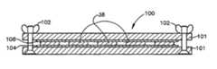
- FIG. 3is a sectional view of the press used to make the piezoelectric actuators of the invention.
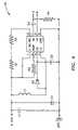
- FIG. 4shows the driver circuit for the piezoelectric actuator used with the pump.
- FIG. 5is a partially diagrammatic view showing an alternative embodiment of the invention in which the pump chamber is reduced in size.
- FIG. 6is a partially diagrammatic view showing another alternative embodiment of a pump in which the inlet and outlet are perpendicular to the plane of the actuator.
- FIG. 1shows how the piezoelectric actuator of the present invention may be used in a miniature diaphragm pump.
- the pump 10is generally in the form of a circular short cylinder. It includes the pump body 12 , piezoelectric actuator 14 , pump cover 16 and piezoelectric actuator electronic driver circuit 18 .
- the pump body 12has lugs 20 for mounting the pump to any substrate. Inlet 22 and outlet 24 are part of the pump body 12 though they could be separate pieces otherwise fastened to the pump body.
- the pump cover 16is essentially the same diameter and of the same material as the pump body 12 . The material would ordinarily be of a standard plastic such as acetal [DELRIN®], PVC, or PC, or of a metal such as stainless steel or brass.
- the cover 16may be fastened to the pump body 12 by any means such as by a fast-curing adhesive while the pump body 12 and cover 16 are under compression such as by clamping.
- the pump coverhas an opening 26 for venting the space above the actuator 14 .
- the dimensions of the pumpdepend on the particular application. In the best mode the pump body 12 is about 40 mm [1.5′′] in diameter.
- a pump chamber 30is formed in the center of the pump body 12 , for example by molding or machining.
- the pump chamber 30is about 28 mm [1.125′′] in diameter or about 3 mm [1 ⁇ 8′′] less in diameter than the diameter of the piezoelectric actuator 14 .
- the chamber 30is about 6 mm [0.25′′] deep.
- a seat 32about 3 mm [0.125′′] wide and about 2 mm [0.070′′] deep is provided in the pump body 12 at the top of the pump chamber 30 .
- the piezoelectric actuator 14is mounted on the seat 32 to form the diaphragm in the top of the pump chamber 30 .
- a sealing washer 34the same diameter as the piezoelectric actuator is put on the seat 32 to seal the pump chamber when the piezoelectric actuator 14 is put in place.
- the sealing washer 34may be of a relatively soft material such as Buna-N or silicon rubber to account for any irregularities in the mating surfaces and ensure a good seal between the actuator 14 and the pump body 12 .
- an o-ring seal 36is placed on top of the piezoelectric actuator 14 to hold the piezoelectric actuator 14 in place and seal it from the cover 16 .
- the cover 16of the same outside diameter as the pump body 12 base but only about 1 ⁇ 8′′ thick is then put in place.
- Sealing washer 34 and o-ring seal 36are referred to collectively as the pump seals, even though they both have the additional function of fixing the actuator 14 in place with respect to the pump body 12 .
- the cover 16is then fastened to the body 12 while under compression, for example by adhesive under clamping pressure, to seal the piezoelectric actuator 14 to the body 12 and fix the actuator 14 in place to allow pumping action.
- the process for making the piezoelectric actuator 14generally is as follows:
- a piezoelectric wafer 38 formed of a polycrystalline ferroelectric material such as PZT5A available from Morgan Electro Ceramicsis obtained. As the name implies this material is actually a ceramic. It is processed into the high displacement piezoelectric actuator 14 by laminating the piezoelectric wafer 38 between a metal substrate layer 40 and an outer metal layer 42 as shown in FIG. 2 ., where the thicknesses of the three layers and the adhesive between them are exaggerated for clarity.
- the bonding agent 41 between the layers 38 and 40is a polyimide adhesive. This lamination process does several things: It ruggedizes the piezoelectric actuator 14 because the metal layers keep the piezoelectric from fracturing during high displacement.
- piezoelectric actuator devicescan be used in environments as hot as a continuous 200° C., compared to only 115° C. for a conventional piezoelectric.
- the significant increase in temperatureis due to the polyimide adhesive used in the bonding process which is unaffected by temperatures up to 200° C.
- Epoxy adhesives used in conventional piezoelectricsnormally can withstand temperatures up to only 115° C. This increase in operating temperature would allow the pumps of this invention to be used in a variety of pump applications, even pumping boiling water continuously.
- the piezoelectric wafers 38are available from the vendor mentioned in various shapes and thicknesses.
- circular wafers 25 mm [1′′] in diameter and 0.2 mm [0.008′′] thickwere found to be optimum.
- Square waferswere tried but did not give maximum displacement. In general the thinner the wafer, the greater the displacement at a given voltage, but the lower the force.
- the 0.2 mm [8-mil] thicknessgives the best flow rate for the diameter of the wafer.
- stainless steel 0.1 mm [0.004′′] thickis used for the substrate layer 40 , the layer in contact with the pumped liquid.
- Stainless steelis chosen for its compatibility with many liquids, including water, its fatigue resistance, its electrical conductivity and its ready availability at low cost.
- Aluminum 0.05 mm [0.001′′] thickis used for the outer layer 42 primarily for its electrical conductivity in transmitting the actuating voltage to the piezoelectric wafer 38 across its surface, but also for its robustness and ready availability at low cost.
- the diameter of the piezoelectric wafer 38being about 25 mm [1′′] as noted above, the diameter of the substrate layer 40 is about 40 mm [1.25′′].
- the setback of the wafer 38 from the edge of the substrate layer 40is an important feature of the invention. This leaves a rim that serves as a clamping surface for the actuator assembly. This means that the entire piezoelectric wafer 38 is free and relatively unconstrained, except insofar as it is bonded to the substrate 40 and the outer layer 42 . This allows maximum displacement of the actuator 14 , ensuring maximum flow of liquid through the pump.
- the diameter of the outer layer 42is smaller than the diameter of the wafer 38 . This setback of the outer layer 42 from the edge of the wafer 38 is done to prevent arcing over of the driving voltage from the outer layer 42 to the substrate layer 40 .
- the piezoelectric actuator of the inventionis flat.
- the actuatoris dome-shaped, it being supposed that this shape is necessary for maximum displacement of the actuator and therefore maximum capacity of the pump for a given size actuator.
- Special molds and methodsare proliferated to produce the shapes of the actuator considered necessary, or to produce a prestress in the actuator that is supposed to increase its displacement.
- Our tests of the inventionhave shown, however, that a dome shape is not necessary, and that the flat actuator has a higher pumping capacity for a given size than any known pump in the prior art. As such the actuator is much simpler to produce in large quantities, as the following will demonstrate.
- the flat shapealso means that the pump may be smaller for a given application.
- a flat actuatoris also inherently easier to mount in any given application than a dome shaped actuator would be.
- pumps using the actuatorhave been shown to have sufficiently long life for numerous applications. Many manufacturers whose names are household words are using or testing this invention.
- the process for making the piezoelectric actuator 14specifically is as follows:
- the press 100is the result of an effort to develop a low cost, rapid process for manufacturing piezoelectric actuators.
- the presstakes advantage of the thermal expansion of the aluminum plates 101 which creates the necessary pressure to cause the polyimide adhesive to bond to the piezoelectric wafer 38 and metal layers 40 , 42 while it is at curing temperature.
- the presscan be put into the oven, and taken out, while the oven is at temperature thereby allowing continuous operation during the manufacturing process.
- the abrupt change in temperaturedoes not affect the piezoelectric actuators 14 since they will remain under pressure even while the press is removed from the oven and allowed to assume room temperature.
- this press processis one of further driving off the solvent and curing the polyimide at a relatively low temperature.
- Prior art processes for making similar piezoelectric actuatorsrequire the mold/press to be taken to much higher temperatures, high enough to melt the polyimide adhesive. Furthermore, since such high temperatures depole the piezoelectric ceramic, it is necessary to pole it again at the end of the process. The present invention eliminates this step altogether, thus contributing to the lower cost of manufacturing the piezoelectric actuators.
- the principle of the piezoelectric actuator pump 10is the same as for any diaphragm pump. Normally the diaphragm in a diaphragm pump is operated by a cam or a pushrod connected to a motor or engine. This is not the case in the piezoelectric actuator pump 10 .
- the piezoelectric actuator 14acts as the diaphragm and moves when a pulsed electric field is imposed across the piezoelectric wafer 38 by means of the enclosing layers 40 and 42 . This varying electric field causes the piezoelectric actuator 14 to expand and contract. As the actuator 14 expands, with its edge constrained, it assumes a slight dome shape as the center of the actuator moves away from the pump chamber 30 . This draws liquid into the pump chamber 30 through the inlet 22 . When the piezoelectric actuator 14 contracts it moves toward the liquid, forcing it out of the pump chamber 30 through outlet 24 .
- Piezoelectric actuatorsperform better when the peak-to-peak voltage is not evenly balanced. They respond better to a positive voltage than the same negative voltage. Thus the circuit 18 has been designed to produce alternating current with the voltage offset to 150 volts positive and 50 volts negative. This is sufficient voltage for the piezoelectric actuator to make a very efficient pump. While a sinusoidal wave will work, at the lower frequencies and voltages, a square wave makes the piezoelectric more efficient. Values of the circuit components in FIG. 4 are as follows:
- U1is an IMP 528 chip designated an electroluminescent lamp driver. In this circuit, with the other components, it serves to shape the pulses and amplify them to the 200 volt peak-to-peak value needed to drive the piezoelectric actuator 14 .
- the values of R 1 and R 2are chosen to vary the frequency of the output between about 35 Hz and about 85 Hz, depending on the particular application.
- This circuitis composed of miniaturized components so it may be contained in a box 302 approximately 25 mm [1′′] square by 6 mm [1 ⁇ 4′′] deep. It has only eleven off-the-shelf surface mount components.
- the box 302may be mounted anywhere in proximity to the pump 10 . In the best mode it is mounted on top of the pump, as shown in FIGS. 1 and 2 , for example by an appropriate adhesive.
- Leads 15run from the driver circuit 18 and are fastened to spring loaded contacts 304 such as those sold by the ECT Company under the trademark POGO®. These contacts 304 are mounted in a box 306 on top of pump cover 16 and project through the pump cover 16 to make contact with the two layers 40 and 42 .
- This small driver circuiteliminates the need for the large power supplies and transformers used in prior art piezoelectric applications.
- the leads 15could be run through an opening in the cover 16 and fastened electrically to the layers 40 and 42 , as by soldering.
- O-ring 36is soft enough to accommodate the soldered point on the substrate layer 42 .
- An inline flex valve 200was invented that is well adapted to the action of the piezoelectric actuator 14 as shown in FIG. 2 .
- the working element of the flex valveis an elliptical disk 202 of polyimide film about 0.05 mm [0.002′′] thick.
- the disk 202is the same size and shape as the end of a short piece of rigid tube 204 formed at about a 45° angle to the axis of the rigid tube 204 .
- the inside diameter of the rigid tube 204is the same as the inside diameter of the inlet 22 or outlet 24 of the pump body 12 .
- Rigid tube 204is captured in the end of the flexible system conduit 206 which slips over the inlet/outlet 22 , 24 and carries the system liquid, as shown in FIG. 2 .
- Valve disk 202is attached to the nether end of the slanted surface at the point designated 203 by any sufficient means such as by adhesive or thermal bonding.
- a similar flex valve 200may be placed in the outlet 24 . Both disks 202 of both valves would point in the same direction downstream. However, it was found in operating the pump 10 that it would pump at full capacity with no valve at all in the outlet. It is postulated that the liquid in the inlet circuit, even with the inlet valve partially open, provides enough inertia to act as a closed inlet valve. Operation with only the inlet valve is considered to be the best mode.
- This flex valve 200is an important feature of the invention. It is of absolute minimum bulk. The mass of the disk 202 is also about as light as it could possibly be so it reacts rapidly to the action of the actuator 14 . When it is open it presents virtually no resistance to the system flow. Mounted at the 45° angle, it has to move through an angle of only 45° to fully open, whereas if it were mounted perpendicular to the flow it would have to move through an angle twice as large. It is of extreme simplicity and low cost of materials and fabrication. Also no part of the valve 200 projects into pump chamber 30 . This minimizes the volume of pump chamber 30 which helps make the pump self-priming and increases its efficiency. Further contributing to these characteristics is that the flex valve 200 is biased closed when the pump is not operating.
- FIGS. 5 and 6show alternative embodiments of the pump of the invention.
- the pump in FIG. 5is essentially the same as that of FIG. 2 except that the pump chamber 30 is reduced in thickness to that of the sealing washer 34 . This improves the self-priming ability of the pump.
- the pump in FIG. 6also has a minimally thick pump chamber 30 . Further, the inlet 22 and outlet 24 are perpendicular to the plane of the actuator 14 , a configuration that may be more convenient in some applications.
- the bottom of the pump bodycomprises a piezoelectric actuator 14 arranged identically but as a mirror image of the piezoelectric actuator 14 just described, with the substrate layers 40 facing each other across the pump chamber 30 .
- two of the pumps above describedare mounted side by side in one pump body.
- the actuator; seals; inlets and outlets, with one-way valve in the inlets only; pump covers; and driversare positioned in one or more of the configurations described above.
- the driversare in series electrically, with the pumps operating in parallel fluidwise in the system in which they are deployed.
- This inventionhas particular application for water cooling of the CPU in computers but may have wider applications wherever a very small pump of relatively high flow rate and minimum power consumption is needed to move liquids at very low cost.
- the piezoelectric actuatorby itself can have very many other applications, such as speakers, audible alarms, automotive sensors, sound generators for active noise cancellation, and accelerometers.
Landscapes
- Engineering & Computer Science (AREA)
- Mechanical Engineering (AREA)
- General Engineering & Computer Science (AREA)
- Manufacturing & Machinery (AREA)
- Reciprocating Pumps (AREA)
Abstract
Description
- I. U.S. Pat. Nos. 5,471,721, 5,632,841, 5,849,125, 6,162,313, 6,042,345, 6,060,811, and 6,071,087 showing either prestressing of piezoelectric actuators, or dome-shaped piezoelectric actuators, or both. This prior art is generally in apposite because the present invention does not use a prestressed or dome-shaped piezoelectric actuator.
- II. U.S. Pat. Nos. 6,179,584, 6,213,735, 5,271,724, 5,759,015, 5,876,187, 6,227,809 showing so-called micropumps. Such pumps generally pump only a drop of fluid at a time; because of the small forces and low Reynolds numbers involved, this prior art is generally in apposite.
- III. U.S. Pat. Nos. 4,034,780, 4,095,615 showing flapper valves. These are flappers mounted on a separate hinge. No prior art was found showing a flex valve with a miniature pump.
- IV. U.S. Pat. Nos. 5,084,345, 4,859,530, 3,936,342, 5,049,421 showing use of polyimide adhesives for various purposes, including bonding metals and other materials to film.
- V. U.S. Pat. Nos. 4,939,405, 5,945,768 showing electrical driver circuits for piezoelectric actuators.
- VI. U.S. Pat. Nos. 6,227,824, 6,033,191, 6,109,889, German WO 87/07218 showing various kinds of pumps incorporating piezoelectric actuators.
- 1. The
piezoelectric wafer 38 and and enclosinglayers - 2. The
piezoelectric wafer 38 is then coated on both sides with athin layer 41, not more than 0.1 mm [0.005″], of a high performance polyimide gel adhesive such as that available from Ranbar Inc. The gel should contain a minimum of 25% solids to allow sufficient material for a good bond after the solvent is driven off - 3. The
piezoelectric wafer 38 is then placed under a standard heat lamp for about 5 minutes to remove most of the solvent from the gel and start the polyimide gel polymerization process. Both sides of the piezoelectric must be cured under the heat lamp since both sides are to be bonded to metal. - 4. Once the adhesive is dry to the touch, the
piezoelectric wafer 38 is then placed between thesubstrate layer 40 and theouter layer 42. - 5. The assembly is placed in a special press. This press was developed specifically for making
piezoelectric actuators 14 and provides uniform temperature and pressure to ensure a good bond between the three components of the actuator. Referring to the best mode shown inFIG. 3 the press comprises two 300 mm [12″] square by 6 mm [¼″] thick plates ofaluminum 101 held together withthumbscrews 102, four on each edge. To ensure uniform pressure while in the press, thebottom plate 101 of the press is covered with a sheet of lowcost polyimide film 104 such as Upilex available from Ube Industries Ltd. Thepiezoelectric actuators 38 are placed on the film and a sheet of high temperature, 4 mm [⅛″]thick rubber 106 is placed over the piezoelectric actuators. The rubber on top and the film on bottom cushion thepiezoelectric actuators 38 providing even distribution of pressure when the press is taken to temperature. Of course other dimensions of the press plates are possible. - 6. Once the piezoelectric actuators are placed in the press the
thumbscrews 102 are made finger tight. - 7. The press is then placed in a standard convection oven for thirty minutes at about 200° C.
- 8. The press is removed from the oven, allowed to cool to a safe temperature, and the
actuators 14 removed from the press.
| 8 to 20 | |||
| R2 | |||
| 8 to 20 MΩ | |||
| R3 | 680 | ||
| R4 | |||
| 1 MΩ | |||
| C1 | 0.1 μF | ||
| C2 | 0.1 μF | ||
| C3 | 0.1 μF[200 v] | ||
| C4 | 0.47 μF[200] | ||
| L1 | 680 μH | ||
| D1 | BAS21 diode | ||
Claims (20)
Priority Applications (2)
| Application Number | Priority Date | Filing Date | Title |
|---|---|---|---|
| US10/380,547US7191503B2 (en) | 2000-09-18 | 2001-09-14 | Method of manufacturing a piezoelectric actuator |
| US11/265,386US20060056999A1 (en) | 2000-09-18 | 2005-11-03 | Piezoelectric actuator and pump using same |
Applications Claiming Priority (3)
| Application Number | Priority Date | Filing Date | Title |
|---|---|---|---|
| US23324800P | 2000-09-18 | 2000-09-18 | |
| PCT/US2001/028947WO2002022358A1 (en) | 2000-09-18 | 2001-09-14 | Piezoelectric actuator and pump using same |
| US10/380,547US7191503B2 (en) | 2000-09-18 | 2001-09-14 | Method of manufacturing a piezoelectric actuator |
Related Child Applications (1)
| Application Number | Title | Priority Date | Filing Date |
|---|---|---|---|
| US11/265,386DivisionUS20060056999A1 (en) | 2000-09-18 | 2005-11-03 | Piezoelectric actuator and pump using same |
Publications (2)
| Publication Number | Publication Date |
|---|---|
| US20040021398A1 US20040021398A1 (en) | 2004-02-05 |
| US7191503B2true US7191503B2 (en) | 2007-03-20 |
Family
ID=22876498
Family Applications (2)
| Application Number | Title | Priority Date | Filing Date |
|---|---|---|---|
| US10/380,547Expired - Fee RelatedUS7191503B2 (en) | 2000-09-18 | 2001-09-14 | Method of manufacturing a piezoelectric actuator |
| US11/265,386AbandonedUS20060056999A1 (en) | 2000-09-18 | 2005-11-03 | Piezoelectric actuator and pump using same |
Family Applications After (1)
| Application Number | Title | Priority Date | Filing Date |
|---|---|---|---|
| US11/265,386AbandonedUS20060056999A1 (en) | 2000-09-18 | 2005-11-03 | Piezoelectric actuator and pump using same |
Country Status (9)
| Country | Link |
|---|---|
| US (2) | US7191503B2 (en) |
| JP (1) | JP2004517240A (en) |
| KR (1) | KR20030034192A (en) |
| CN (1) | CN1269637C (en) |
| CA (1) | CA2431677A1 (en) |
| DE (1) | DE10196634T5 (en) |
| GB (1) | GB2387965B (en) |
| MX (1) | MXPA03002388A (en) |
| WO (1) | WO2002022358A1 (en) |
Cited By (13)
| Publication number | Priority date | Publication date | Assignee | Title |
|---|---|---|---|---|
| US20060083639A1 (en)* | 2004-10-12 | 2006-04-20 | Industrial Technology Research Institute | PDMS valve-less micro pump structure and method for producing the same |
| US20060232171A1 (en)* | 2005-04-13 | 2006-10-19 | Par Technologies, Llc | Piezoelectric diaphragm assembly with conductors on flexible film |
| US20060255064A1 (en)* | 2005-05-10 | 2006-11-16 | Par Technologies, Llc | Fluid container with integrated valve |
| US20080018200A1 (en)* | 2004-04-02 | 2008-01-24 | Adaptivenergy, Llc | Piezoelectric devices and methods and circuits for driving same |
| US20080174620A1 (en)* | 2006-10-03 | 2008-07-24 | Adaptivenergy, Llc. | Synthetic jets |
| US20080246367A1 (en)* | 2006-12-29 | 2008-10-09 | Adaptivenergy, Llc | Tuned laminated piezoelectric elements and methods of tuning same |
| US20080304983A1 (en)* | 2007-06-08 | 2008-12-11 | Satoshi Yamada | Diaphragm air pump |
| US20090174289A1 (en)* | 2007-12-28 | 2009-07-09 | Adaptivenergy Llc | Magnetic impulse energy harvesting device and method |
| US20090313798A1 (en)* | 2006-12-29 | 2009-12-24 | Adaptiv Energy ,Llc | Rugged piezoelectric actuators and methods of fabricating same |
| US20100156245A1 (en)* | 2008-12-23 | 2010-06-24 | Research In Motion Limited | Coating for actuator and method of applying coating |
| US20110141691A1 (en)* | 2009-12-11 | 2011-06-16 | Slaton David S | Systems and methods for manufacturing synthetic jets |
| US20240026871A1 (en)* | 2020-12-09 | 2024-01-25 | Sony Group Corporation | Diaphragm pump, electronic apparatus, manufacturing apparatus, and manufacturing method |
| US12404850B2 (en) | 2018-05-18 | 2025-09-02 | Fraunhofer-Gesellschaft zur Förderung der angewandten Forschung e.V. | Method for producing a micropump with mechanically biased diaphragm actuator |
Families Citing this family (57)
| Publication number | Priority date | Publication date | Assignee | Title |
|---|---|---|---|---|
| US6451017B1 (en)* | 2000-01-10 | 2002-09-17 | Hydrocision, Inc. | Surgical instruments with integrated electrocautery |
| GB0208687D0 (en)* | 2002-04-16 | 2002-05-29 | Davis John B | Elastomer-glass fluid control elements |
| JP4279662B2 (en)* | 2003-12-26 | 2009-06-17 | アルプス電気株式会社 | Small pump |
| US7538473B2 (en)* | 2004-02-03 | 2009-05-26 | S.C. Johnson & Son, Inc. | Drive circuits and methods for ultrasonic piezoelectric actuators |
| US7723899B2 (en) | 2004-02-03 | 2010-05-25 | S.C. Johnson & Son, Inc. | Active material and light emitting device |
| US7312554B2 (en)* | 2004-04-02 | 2007-12-25 | Adaptivenergy, Llc | Piezoelectric devices and methods and circuits for driving same |
| US7290993B2 (en)* | 2004-04-02 | 2007-11-06 | Adaptivenergy Llc | Piezoelectric devices and methods and circuits for driving same |
| US20050225201A1 (en)* | 2004-04-02 | 2005-10-13 | Par Technologies, Llc | Piezoelectric devices and methods and circuits for driving same |
| US7484940B2 (en)* | 2004-04-28 | 2009-02-03 | Kinetic Ceramics, Inc. | Piezoelectric fluid pump |
| US7219848B2 (en) | 2004-11-03 | 2007-05-22 | Meadwestvaco Corporation | Fluid sprayer employing piezoelectric pump |
| JP3949135B2 (en)* | 2004-11-17 | 2007-07-25 | シャープ株式会社 | Piezoelectric pump and Stirling refrigerator |
| US7267043B2 (en) | 2004-12-30 | 2007-09-11 | Adaptivenergy, Llc | Actuators with diaphragm and methods of operating same |
| US20060147329A1 (en)* | 2004-12-30 | 2006-07-06 | Tanner Edward T | Active valve and active valving for pump |
| US7258533B2 (en) | 2004-12-30 | 2007-08-21 | Adaptivenergy, Llc | Method and apparatus for scavenging energy during pump operation |
| US20060232167A1 (en)* | 2005-04-13 | 2006-10-19 | Par Technologies Llc | Piezoelectric diaphragm with aperture(s) |
| US20060245949A1 (en)* | 2005-04-13 | 2006-11-02 | Par Technologies, Llc | Electromagnetically bonded pumps and pump subassemblies and methods of fabrication |
| US20060245951A1 (en)* | 2005-04-13 | 2006-11-02 | Par Technologies, Llc | Multilayer valve structures, methods of making, and pumps using same |
| US20060232162A1 (en)* | 2005-04-13 | 2006-10-19 | Par Technologies, Llc | Electrically driven mechanical actuators and methods of operating same |
| US20060232166A1 (en)* | 2005-04-13 | 2006-10-19 | Par Technologies Llc | Stacked piezoelectric diaphragm members |
| JP4887652B2 (en)* | 2005-04-21 | 2012-02-29 | ソニー株式会社 | Jet generator and electronic device |
| CN100335779C (en)* | 2005-07-15 | 2007-09-05 | 清华大学 | Travelling wave driven prezoelectric ceramic pump capable of realizing forward-reverse fluid flow |
| US20070075286A1 (en)* | 2005-10-04 | 2007-04-05 | Par Technologies, Llc | Piezoelectric valves drive |
| US20070129681A1 (en)* | 2005-11-01 | 2007-06-07 | Par Technologies, Llc | Piezoelectric actuation of piston within dispensing chamber |
| JP4805658B2 (en)* | 2005-11-09 | 2011-11-02 | 日東工器株式会社 | Pump using unimorph diaphragm |
| WO2007061610A1 (en)* | 2005-11-18 | 2007-05-31 | Par Technologies, Llc | Human powered piezoelectric power generating device |
| TW200728605A (en)* | 2006-01-20 | 2007-08-01 | Univ Tamkang | Thermo-buckled micro-actuator unit made of polymer with high thermal expansion coefficient |
| CN101438057A (en)* | 2006-03-07 | 2009-05-20 | 流体公司 | Fluidic energy transfer devices |
| US20070267940A1 (en)* | 2006-05-15 | 2007-11-22 | Par Technologies, Llc. | Compressor and compression using motion amplification |
| JP2008038829A (en)* | 2006-08-09 | 2008-02-21 | Alps Electric Co Ltd | Piezoelectric pump and piezoelectric vibrator |
| CN101490419B (en)* | 2006-12-09 | 2011-02-02 | 株式会社村田制作所 | Piezoelectric pump |
| JP4848319B2 (en)* | 2007-02-16 | 2011-12-28 | アルプス電気株式会社 | Piezoelectric pump |
| US20090050299A1 (en)* | 2007-08-21 | 2009-02-26 | Tektronix, Inc. | Cooling facility for an electronic component |
| JP4840505B2 (en)* | 2007-12-03 | 2011-12-21 | 株式会社村田製作所 | Piezoelectric pump |
| JP2009293507A (en)* | 2008-06-05 | 2009-12-17 | Alps Electric Co Ltd | Piezoelectric pump |
| TW201011954A (en)* | 2008-09-15 | 2010-03-16 | Micro Base Technology Corp | Conduction wire structure applied to the inner of micro piezoelectric pump |
| CN101404260B (en)* | 2008-10-14 | 2010-06-02 | 江苏稳润光电有限公司 | LED display packaging method |
| US8215930B2 (en)* | 2008-10-30 | 2012-07-10 | Phillips 66 Company | Diaphragm pumps and transporting drag reducers |
| WO2010050982A1 (en)* | 2008-10-31 | 2010-05-06 | Hewlett-Packard Development Company, L.P. | Electrostatic liquid-ejection actuation mechanism |
| CN102459899B (en)* | 2009-06-03 | 2016-05-11 | Kci医疗资源有限公司 | Pumps with Disc Chamber |
| RU2011154213A (en)* | 2009-06-03 | 2013-07-20 | ДЗЕ ТЕКНОЛОДЖИ ПАРТНЕРШИП ПиЭлСи | HYDRAULIC DISK PUMP |
| CA2711021C (en) | 2009-10-13 | 2013-09-17 | Research In Motion Limited | Coating for actuator and method of applying coating |
| KR101363554B1 (en)* | 2009-12-04 | 2014-02-18 | 가부시키가이샤 무라타 세이사쿠쇼 | Piezoelectric micro-blower |
| CN103026066A (en)* | 2010-08-09 | 2013-04-03 | 凯希特许有限公司 | Systems and methods for measuring pressure applied by a piezoelectric pump |
| US20120170216A1 (en)* | 2011-01-04 | 2012-07-05 | General Electric Company | Synthetic jet packaging |
| US20130069488A1 (en)* | 2011-07-01 | 2013-03-21 | Lockheed Martin Corporation | Piezoelectric pressure sensitive transducer apparatus and method |
| CN102652634B (en)* | 2012-05-11 | 2014-02-05 | 赵亨来 | Heart-type circulation device |
| DE102012010509B4 (en)* | 2012-05-21 | 2021-10-28 | Fraunhofer-Gesellschaft zur Förderung der angewandten Forschung e.V. | Device for generating a flow |
| JP6428769B2 (en)* | 2014-04-30 | 2018-11-28 | 株式会社村田製作所 | Inhaler |
| CN104373325B (en)* | 2014-10-11 | 2016-08-24 | 北京联合大学 | Arcuate segments equal pipe Valveless piezoelectric pump |
| TWI602995B (en) | 2016-09-05 | 2017-10-21 | 研能科技股份有限公司 | Fluid control device |
| TWI625468B (en) | 2016-09-05 | 2018-06-01 | 研能科技股份有限公司 | Fluid control device |
| TWI613367B (en) | 2016-09-05 | 2018-02-01 | 研能科技股份有限公司 | Fluid control device |
| DE102016123774B3 (en)* | 2016-12-08 | 2018-02-01 | Makita Corporation | A carburettor for an internal combustion engine of an implement and method for controlling a fuel flow in an idling operation of a carburetor |
| CN110792746B (en)* | 2019-09-04 | 2023-07-14 | 鲁班嫡系机器人(深圳)有限公司 | Piezoelectric driving device and equipment |
| IT202100023240A1 (en)* | 2021-09-08 | 2023-03-08 | St Microelectronics Srl | MEMS ACTUATOR AND RELATED MANUFACTURING PROCESS |
| TWI817615B (en)* | 2022-07-18 | 2023-10-01 | 研能科技股份有限公司 | Fluid pump module |
| CN119393323B (en)* | 2024-12-31 | 2025-05-02 | 恒脉微电子(杭州)有限公司 | A synthetic jet pump device with lateral air outlet |
Citations (49)
| Publication number | Priority date | Publication date | Assignee | Title |
|---|---|---|---|---|
| US2731419A (en)* | 1954-08-12 | 1956-01-17 | Gen Electric | Ferroelectric ceramic composition |
| US3936342A (en) | 1973-02-15 | 1976-02-03 | Toagosei Chemical Industry Co., Ltd. | Steel plate bonding process and primer composition |
| US3960635A (en) | 1971-06-07 | 1976-06-01 | N.V. Hollandse Signaalapparaten | Method for the fabrication of printed circuits |
| US4034780A (en) | 1976-01-26 | 1977-07-12 | Aquology Corporation | Check valve |
| US4095615A (en) | 1976-05-21 | 1978-06-20 | Ramco Manufacturing, Inc. | Check valve and siphon tube assembly employing same |
| GB2013311A (en) | 1978-01-28 | 1979-08-08 | Freudenberg Carl | Nonreturn valves |
| JPS592385A (en)* | 1982-06-28 | 1984-01-07 | Murata Mfg Co Ltd | Electronic parts |
| US4431937A (en)* | 1981-10-26 | 1984-02-14 | Sfe Technologies | Piezoelectric crystal assembly including protective mounting and covering means |
| GB2161902A (en) | 1984-07-18 | 1986-01-22 | Black & Decker Inc | Non-return flap valve for vacuum cleaner |
| EP0202836A1 (en) | 1985-05-14 | 1986-11-26 | AlliedSignal Inc. | Air supply pump |
| WO1987007218A1 (en) | 1986-05-30 | 1987-12-03 | Siemens Aktiengesellschaft | Piezoelectrically operated fluid pump |
| US4859530A (en) | 1987-07-09 | 1989-08-22 | Ethyl Corporation | High temperature adhesive for polymide films |
| US4939405A (en) | 1987-12-28 | 1990-07-03 | Misuzuerie Co. Ltd. | Piezo-electric vibrator pump |
| JPH02276280A (en)* | 1989-04-18 | 1990-11-13 | Toyota Motor Corp | piezoelectric laminate |
| US5049421A (en) | 1989-01-30 | 1991-09-17 | Dresser Industries, Inc. | Transducer glass bonding technique |
| US5084345A (en) | 1990-11-26 | 1992-01-28 | E. I. Du Pont De Nemours And Company | Laminates utilizing chemically etchable adhesives |
| GB2250911A (en) | 1990-12-17 | 1992-06-24 | Zanussi Elettrodomestici | Dishwasher with discharge pump and non-return valve |
| US5156710A (en)* | 1991-05-06 | 1992-10-20 | International Business Machines Corporation | Method of laminating polyimide to thin sheet metal |
| GB2262972A (en) | 1990-12-17 | 1993-07-07 | Rapid Developments Limited | One way valve |
| US5271724A (en) | 1990-08-31 | 1993-12-21 | Westonbridge International Limited | Valve equipped with a position detector and a micropump incorporating said valve |
| US5338164A (en) | 1993-05-28 | 1994-08-16 | Rockwell International Corporation | Positive displacement micropump |
| US5471721A (en) | 1993-02-23 | 1995-12-05 | Research Corporation Technologies, Inc. | Method for making monolithic prestressed ceramic devices |
| US5632841A (en) | 1995-04-04 | 1997-05-27 | The United States Of America As Represented By The Administrator Of The National Aeronautics And Space Administration | Thin layer composite unimorph ferroelectric driver and sensor |
| US5759015A (en) | 1993-12-28 | 1998-06-02 | Westonbridge International Limited | Piezoelectric micropump having actuation electrodes and stopper members |
| US5816780A (en) | 1997-04-15 | 1998-10-06 | Face International Corp. | Piezoelectrically actuated fluid pumps |
| US5849125A (en)* | 1997-02-07 | 1998-12-15 | Clark; Stephen E. | Method of manufacturing flextensional transducer using pre-curved piezoelectric ceramic layer |
| US5854380A (en)* | 1996-06-07 | 1998-12-29 | Unitika Ltd. | Polyimide precursor solution process for the production thereof coating or film obtained therefrom and process for producing the film |
| US5876187A (en) | 1995-03-09 | 1999-03-02 | University Of Washington | Micropumps with fixed valves |
| US5909905A (en) | 1995-09-07 | 1999-06-08 | The United States Of America As Represented By The Administrator Of The National Aeronautics And Space Administration | Method of making thermally stable, piezoelectric and proelectric polymeric substrates |
| US5945768A (en) | 1997-05-08 | 1999-08-31 | Alliedsignal Inc. | Piezoelectric drive circuit |
| US6030480A (en) | 1997-07-25 | 2000-02-29 | Face International Corp. | Method for manufacturing multi-layered high-deformation piezoelectric actuators and sensors |
| US6033191A (en) | 1997-05-16 | 2000-03-07 | Institut Fur Mikrotechnik Mainz Gmbh | Micromembrane pump |
| US6042345A (en) | 1997-04-15 | 2000-03-28 | Face International Corporation | Piezoelectrically actuated fluid pumps |
| US6052300A (en) | 1998-11-09 | 2000-04-18 | Face International Corporation | DC-AC converter circuit using resonating multi-layer piezoelectric transformer |
| US6060811A (en) | 1997-07-25 | 2000-05-09 | The United States Of America As Represented By The United States National Aeronautics And Space Administration | Advanced layered composite polylaminate electroactive actuator and sensor |
| US6071088A (en) | 1997-04-15 | 2000-06-06 | Face International Corp. | Piezoelectrically actuated piston pump |
| US6071087A (en) | 1996-04-03 | 2000-06-06 | The United States Of America As Represented By The Administrator Of The National Aeronautics And Space Administration | Ferroelectric pump |
| US6104127A (en) | 1997-05-14 | 2000-08-15 | Honda Giken Kogyo Kabushiki Kaisha | Piezoelectric type actuator having stable resonance frequency |
| US6109889A (en) | 1995-12-13 | 2000-08-29 | Hahn-Schickard-Gesellschaft Fur Angewandte Forschung E.V. | Fluid pump |
| US6114797A (en) | 1997-05-27 | 2000-09-05 | Face International Corp. | Ignition circuit with piezoelectric transformer |
| US6124678A (en) | 1998-10-08 | 2000-09-26 | Face International Corp. | Fluorescent lamp excitation circuit having a multi-layer piezoelectric acoustic transformer and methods for using the same |
| US6156145A (en) | 1998-08-21 | 2000-12-05 | Face International Corp. | Method of manufacturing multi-layered flextensional piezoelectric transducer |
| US6162313A (en) | 1997-07-29 | 2000-12-19 | Eurocopter Deutschland Gmbh | Method for producing a composite structure including a piezoelectric element |
| US6179584B1 (en) | 1996-12-11 | 2001-01-30 | Gesim Gesellschaft Fur Silizium-Mikrosysteme Mbh | Microejector pump |
| US6213735B1 (en) | 1996-11-22 | 2001-04-10 | Evotec Biosystem Ag | Micromechanical ejection pump for separating small fluid volumes from a flowing sample fluid |
| US6227809B1 (en) | 1995-03-09 | 2001-05-08 | University Of Washington | Method for making micropumps |
| US6227824B1 (en) | 1995-09-15 | 2001-05-08 | HAN-SCHICKARD-GESELLSCHAFT FüR ANGEWANDTE FORSCHUNG E.V. | Fluid pump without non-return valves |
| US6512323B2 (en) | 2000-03-22 | 2003-01-28 | Caterpillar Inc. | Piezoelectric actuator device |
| US7070674B2 (en) | 2002-12-20 | 2006-07-04 | Caterpillar | Method of manufacturing a multi-layered piezoelectric actuator |
Family Cites Families (5)
| Publication number | Priority date | Publication date | Assignee | Title |
|---|---|---|---|---|
| US3029743A (en)* | 1960-04-14 | 1962-04-17 | Curtiss Wright Corp | Ceramic diaphragm pump |
| US3963380A (en)* | 1975-01-06 | 1976-06-15 | Thomas Jr Lyell J | Micro pump powered by piezoelectric disk benders |
| US4056654A (en)* | 1975-07-24 | 1977-11-01 | Kkf Corporation | Coating compositions, processes for depositing the same, and articles resulting therefrom |
| DE3724290A1 (en)* | 1987-07-22 | 1989-02-02 | Siemens Ag | ELECTRODE FOR PIEZOELECTRIC COMPOSITES |
| US6152323A (en)* | 1998-06-19 | 2000-11-28 | Immel; Nancy K. | Liquid container dispensing apparatus |
- 2001
- 2001-09-14JPJP2002526587Apatent/JP2004517240A/enactivePending
- 2001-09-14CNCNB01818796XApatent/CN1269637C/ennot_activeExpired - Fee Related
- 2001-09-14WOPCT/US2001/028947patent/WO2002022358A1/enactiveSearch and Examination
- 2001-09-14DEDE10196634Tpatent/DE10196634T5/ennot_activeWithdrawn
- 2001-09-14KRKR10-2003-7003953Apatent/KR20030034192A/ennot_activeWithdrawn
- 2001-09-14GBGB0308623Apatent/GB2387965B/ennot_activeExpired - Fee Related
- 2001-09-14CACA002431677Apatent/CA2431677A1/ennot_activeAbandoned
- 2001-09-14MXMXPA03002388Apatent/MXPA03002388A/enunknown
- 2001-09-14USUS10/380,547patent/US7191503B2/ennot_activeExpired - Fee Related
- 2005
- 2005-11-03USUS11/265,386patent/US20060056999A1/ennot_activeAbandoned
Patent Citations (53)
| Publication number | Priority date | Publication date | Assignee | Title |
|---|---|---|---|---|
| US2731419A (en)* | 1954-08-12 | 1956-01-17 | Gen Electric | Ferroelectric ceramic composition |
| US3960635A (en) | 1971-06-07 | 1976-06-01 | N.V. Hollandse Signaalapparaten | Method for the fabrication of printed circuits |
| US3936342A (en) | 1973-02-15 | 1976-02-03 | Toagosei Chemical Industry Co., Ltd. | Steel plate bonding process and primer composition |
| US4034780A (en) | 1976-01-26 | 1977-07-12 | Aquology Corporation | Check valve |
| US4095615A (en) | 1976-05-21 | 1978-06-20 | Ramco Manufacturing, Inc. | Check valve and siphon tube assembly employing same |
| GB2013311A (en) | 1978-01-28 | 1979-08-08 | Freudenberg Carl | Nonreturn valves |
| US4431937A (en)* | 1981-10-26 | 1984-02-14 | Sfe Technologies | Piezoelectric crystal assembly including protective mounting and covering means |
| JPS592385A (en)* | 1982-06-28 | 1984-01-07 | Murata Mfg Co Ltd | Electronic parts |
| GB2161902A (en) | 1984-07-18 | 1986-01-22 | Black & Decker Inc | Non-return flap valve for vacuum cleaner |
| EP0202836A1 (en) | 1985-05-14 | 1986-11-26 | AlliedSignal Inc. | Air supply pump |
| WO1987007218A1 (en) | 1986-05-30 | 1987-12-03 | Siemens Aktiengesellschaft | Piezoelectrically operated fluid pump |
| US4859530A (en) | 1987-07-09 | 1989-08-22 | Ethyl Corporation | High temperature adhesive for polymide films |
| US4939405A (en) | 1987-12-28 | 1990-07-03 | Misuzuerie Co. Ltd. | Piezo-electric vibrator pump |
| US5049421A (en) | 1989-01-30 | 1991-09-17 | Dresser Industries, Inc. | Transducer glass bonding technique |
| JPH02276280A (en)* | 1989-04-18 | 1990-11-13 | Toyota Motor Corp | piezoelectric laminate |
| US5271724A (en) | 1990-08-31 | 1993-12-21 | Westonbridge International Limited | Valve equipped with a position detector and a micropump incorporating said valve |
| US5084345A (en) | 1990-11-26 | 1992-01-28 | E. I. Du Pont De Nemours And Company | Laminates utilizing chemically etchable adhesives |
| GB2262972A (en) | 1990-12-17 | 1993-07-07 | Rapid Developments Limited | One way valve |
| GB2250911A (en) | 1990-12-17 | 1992-06-24 | Zanussi Elettrodomestici | Dishwasher with discharge pump and non-return valve |
| US5156710A (en)* | 1991-05-06 | 1992-10-20 | International Business Machines Corporation | Method of laminating polyimide to thin sheet metal |
| US5589725A (en) | 1993-02-23 | 1996-12-31 | Research Corporation Tech., Inc. | Monolithic prestressed ceramic devices and method for making same |
| US5471721A (en) | 1993-02-23 | 1995-12-05 | Research Corporation Technologies, Inc. | Method for making monolithic prestressed ceramic devices |
| US5338164A (en) | 1993-05-28 | 1994-08-16 | Rockwell International Corporation | Positive displacement micropump |
| US5759015A (en) | 1993-12-28 | 1998-06-02 | Westonbridge International Limited | Piezoelectric micropump having actuation electrodes and stopper members |
| US5876187A (en) | 1995-03-09 | 1999-03-02 | University Of Washington | Micropumps with fixed valves |
| US6227809B1 (en) | 1995-03-09 | 2001-05-08 | University Of Washington | Method for making micropumps |
| US5632841A (en) | 1995-04-04 | 1997-05-27 | The United States Of America As Represented By The Administrator Of The National Aeronautics And Space Administration | Thin layer composite unimorph ferroelectric driver and sensor |
| US6734603B2 (en) | 1995-04-04 | 2004-05-11 | The United States Of America As Represented By The National Aeronautics And Space Administration | Thin layer composite unimorph ferroelectric driver and sensor |
| US6379809B1 (en) | 1995-09-07 | 2002-04-30 | The United States Of America As Represented By The Administrator Of The National Aeronautics And Space Administration | Thermally stable, piezoelectric and pyroelectric polymeric substrates and method relating thereto |
| US5909905A (en) | 1995-09-07 | 1999-06-08 | The United States Of America As Represented By The Administrator Of The National Aeronautics And Space Administration | Method of making thermally stable, piezoelectric and proelectric polymeric substrates |
| US6227824B1 (en) | 1995-09-15 | 2001-05-08 | HAN-SCHICKARD-GESELLSCHAFT FüR ANGEWANDTE FORSCHUNG E.V. | Fluid pump without non-return valves |
| US6109889A (en) | 1995-12-13 | 2000-08-29 | Hahn-Schickard-Gesellschaft Fur Angewandte Forschung E.V. | Fluid pump |
| US6071087A (en) | 1996-04-03 | 2000-06-06 | The United States Of America As Represented By The Administrator Of The National Aeronautics And Space Administration | Ferroelectric pump |
| US5854380A (en)* | 1996-06-07 | 1998-12-29 | Unitika Ltd. | Polyimide precursor solution process for the production thereof coating or film obtained therefrom and process for producing the film |
| US6213735B1 (en) | 1996-11-22 | 2001-04-10 | Evotec Biosystem Ag | Micromechanical ejection pump for separating small fluid volumes from a flowing sample fluid |
| US6179584B1 (en) | 1996-12-11 | 2001-01-30 | Gesim Gesellschaft Fur Silizium-Mikrosysteme Mbh | Microejector pump |
| US5849125A (en)* | 1997-02-07 | 1998-12-15 | Clark; Stephen E. | Method of manufacturing flextensional transducer using pre-curved piezoelectric ceramic layer |
| US6042345A (en) | 1997-04-15 | 2000-03-28 | Face International Corporation | Piezoelectrically actuated fluid pumps |
| US5816780A (en) | 1997-04-15 | 1998-10-06 | Face International Corp. | Piezoelectrically actuated fluid pumps |
| US6071088A (en) | 1997-04-15 | 2000-06-06 | Face International Corp. | Piezoelectrically actuated piston pump |
| US5945768A (en) | 1997-05-08 | 1999-08-31 | Alliedsignal Inc. | Piezoelectric drive circuit |
| US6104127A (en) | 1997-05-14 | 2000-08-15 | Honda Giken Kogyo Kabushiki Kaisha | Piezoelectric type actuator having stable resonance frequency |
| US6033191A (en) | 1997-05-16 | 2000-03-07 | Institut Fur Mikrotechnik Mainz Gmbh | Micromembrane pump |
| US6114797A (en) | 1997-05-27 | 2000-09-05 | Face International Corp. | Ignition circuit with piezoelectric transformer |
| US6030480A (en) | 1997-07-25 | 2000-02-29 | Face International Corp. | Method for manufacturing multi-layered high-deformation piezoelectric actuators and sensors |
| US6060811A (en) | 1997-07-25 | 2000-05-09 | The United States Of America As Represented By The United States National Aeronautics And Space Administration | Advanced layered composite polylaminate electroactive actuator and sensor |
| US6162313A (en) | 1997-07-29 | 2000-12-19 | Eurocopter Deutschland Gmbh | Method for producing a composite structure including a piezoelectric element |
| US6257293B1 (en) | 1998-07-21 | 2001-07-10 | Face International Corp. | Apparatus for manufacturing multi-layered high deformation piezoelectric actuators and sensors |
| US6156145A (en) | 1998-08-21 | 2000-12-05 | Face International Corp. | Method of manufacturing multi-layered flextensional piezoelectric transducer |
| US6124678A (en) | 1998-10-08 | 2000-09-26 | Face International Corp. | Fluorescent lamp excitation circuit having a multi-layer piezoelectric acoustic transformer and methods for using the same |
| US6052300A (en) | 1998-11-09 | 2000-04-18 | Face International Corporation | DC-AC converter circuit using resonating multi-layer piezoelectric transformer |
| US6512323B2 (en) | 2000-03-22 | 2003-01-28 | Caterpillar Inc. | Piezoelectric actuator device |
| US7070674B2 (en) | 2002-12-20 | 2006-07-04 | Caterpillar | Method of manufacturing a multi-layered piezoelectric actuator |
Non-Patent Citations (4)
| Title |
|---|
| GB Examination Report mailed Jun. 4, 2004 in corresponding GB application No. GB0308623.8. |
| GB Examination Report mailed Nov. 9, 2004 in corresponding GB application No. GB0423682.4. |
| International Preliminary Examination Report mailed Oct. 3, 2002 in corresponding PCT Application PCT/US01/28947. |
| International Search Report mailed Jan. 24, 2002 in corresponding PCT Application No. PCT/US01/28947. |
Cited By (16)
| Publication number | Priority date | Publication date | Assignee | Title |
|---|---|---|---|---|
| US7969064B2 (en)* | 2004-04-02 | 2011-06-28 | Par Technologies, Llc. | Piezoelectric devices and methods and circuits for driving same |
| US20080018200A1 (en)* | 2004-04-02 | 2008-01-24 | Adaptivenergy, Llc | Piezoelectric devices and methods and circuits for driving same |
| US20060083639A1 (en)* | 2004-10-12 | 2006-04-20 | Industrial Technology Research Institute | PDMS valve-less micro pump structure and method for producing the same |
| US20060232171A1 (en)* | 2005-04-13 | 2006-10-19 | Par Technologies, Llc | Piezoelectric diaphragm assembly with conductors on flexible film |
| US20060255064A1 (en)* | 2005-05-10 | 2006-11-16 | Par Technologies, Llc | Fluid container with integrated valve |
| US20060264829A1 (en)* | 2005-05-10 | 2006-11-23 | Par Technologies, Llc | Disposable fluid container with integrated pump motive assembly |
| US20080174620A1 (en)* | 2006-10-03 | 2008-07-24 | Adaptivenergy, Llc. | Synthetic jets |
| US20090313798A1 (en)* | 2006-12-29 | 2009-12-24 | Adaptiv Energy ,Llc | Rugged piezoelectric actuators and methods of fabricating same |
| US20080246367A1 (en)* | 2006-12-29 | 2008-10-09 | Adaptivenergy, Llc | Tuned laminated piezoelectric elements and methods of tuning same |
| US20080304983A1 (en)* | 2007-06-08 | 2008-12-11 | Satoshi Yamada | Diaphragm air pump |
| US20090174289A1 (en)* | 2007-12-28 | 2009-07-09 | Adaptivenergy Llc | Magnetic impulse energy harvesting device and method |
| US20100156245A1 (en)* | 2008-12-23 | 2010-06-24 | Research In Motion Limited | Coating for actuator and method of applying coating |
| US8179027B2 (en)* | 2008-12-23 | 2012-05-15 | Research In Motion Limited | Coating for actuator and method of applying coating |
| US20110141691A1 (en)* | 2009-12-11 | 2011-06-16 | Slaton David S | Systems and methods for manufacturing synthetic jets |
| US12404850B2 (en) | 2018-05-18 | 2025-09-02 | Fraunhofer-Gesellschaft zur Förderung der angewandten Forschung e.V. | Method for producing a micropump with mechanically biased diaphragm actuator |
| US20240026871A1 (en)* | 2020-12-09 | 2024-01-25 | Sony Group Corporation | Diaphragm pump, electronic apparatus, manufacturing apparatus, and manufacturing method |
Also Published As
| Publication number | Publication date |
|---|---|
| GB0308623D0 (en) | 2003-05-21 |
| US20060056999A1 (en) | 2006-03-16 |
| CA2431677A1 (en) | 2002-03-21 |
| CN1474749A (en) | 2004-02-11 |
| KR20030034192A (en) | 2003-05-01 |
| MXPA03002388A (en) | 2004-09-06 |
| JP2004517240A (en) | 2004-06-10 |
| CN1269637C (en) | 2006-08-16 |
| WO2002022358A1 (en) | 2002-03-21 |
| GB2387965A (en) | 2003-10-29 |
| US20040021398A1 (en) | 2004-02-05 |
| GB2387965B (en) | 2005-05-18 |
| DE10196634T5 (en) | 2005-04-07 |
Similar Documents
| Publication | Publication Date | Title |
|---|---|---|
| US7191503B2 (en) | Method of manufacturing a piezoelectric actuator | |
| US7198250B2 (en) | Piezoelectric actuator and pump using same | |
| EP2568176B1 (en) | Fluid control device | |
| EP2568174B1 (en) | Fluid control device | |
| US6450773B1 (en) | Piezoelectric vacuum pump and method | |
| CN108050051B (en) | Fluid control device and pump | |
| US6261066B1 (en) | Micromembrane pump | |
| EP2767715B1 (en) | Fluid-control device, and method for adjusting fluid-control device | |
| EP2568175B1 (en) | Fluid control device | |
| US6395638B1 (en) | Method for producing a micromembrane pump body | |
| CA2878279C (en) | Systems and methods for regulating the resonant frequency of a disc pump cavity | |
| EP2568177A1 (en) | Fluid control device | |
| US20090148318A1 (en) | Piezoelectric Pump | |
| EP2092406A1 (en) | Thermal management system for embedded environment and method for making same | |
| JP2014240662A (en) | Fluid control device | |
| GB2403846A (en) | Piezoelectric actuator and pump | |
| JP2007146778A (en) | Bending oscillator and diaphragm type pump | |
| JP2007138884A (en) | Piezoelectric pump |
Legal Events
| Date | Code | Title | Description |
|---|---|---|---|
| AS | Assignment | Owner name:PAR TECHNOLOGIES LLC, VIRGINIA Free format text:ASSIGNMENT OF ASSIGNORS INTEREST;ASSIGNOR:EAST, W. JOE;REEL/FRAME:014167/0883 Effective date:20030521 | |
| AS | Assignment | Owner name:PARKER-HANNIFIN CORPORATION, OHIO Free format text:SECURITY AGREEMENT;ASSIGNOR:PAR TECHNOLOGIES, LLC;REEL/FRAME:018507/0606 Effective date:20061012 | |
| STCF | Information on status: patent grant | Free format text:PATENTED CASE | |
| AS | Assignment | Owner name:ADAPTIVENERGY, LLC, VIRGINIA Free format text:CHANGE OF NAME;ASSIGNOR:PAR TECHNOLOGIES, LLC;REEL/FRAME:019580/0180 Effective date:20070419 | |
| REMI | Maintenance fee reminder mailed | ||
| AS | Assignment | Owner name:PAR TECHNOLOGIES, LLC, DISTRICT OF COLUMBIA Free format text:CHANGE OF NAME;ASSIGNOR:ADAPTIVENERGY, LLC;REEL/FRAME:025627/0066 Effective date:20101109 | |
| FPAY | Fee payment | Year of fee payment:4 | |
| SULP | Surcharge for late payment | ||
| FPAY | Fee payment | Year of fee payment:8 | |
| AS | Assignment | Owner name:PARKER HANNIFIN CORPORATION, OHIO Free format text:ASSIGNMENT OF ASSIGNORS INTEREST;ASSIGNOR:PAR TECHNOLOGIES, LLC;REEL/FRAME:035162/0214 Effective date:20141229 | |
| FEPP | Fee payment procedure | Free format text:MAINTENANCE FEE REMINDER MAILED (ORIGINAL EVENT CODE: REM.); ENTITY STATUS OF PATENT OWNER: LARGE ENTITY | |
| LAPS | Lapse for failure to pay maintenance fees | Free format text:PATENT EXPIRED FOR FAILURE TO PAY MAINTENANCE FEES (ORIGINAL EVENT CODE: EXP.); ENTITY STATUS OF PATENT OWNER: LARGE ENTITY | |
| STCH | Information on status: patent discontinuation | Free format text:PATENT EXPIRED DUE TO NONPAYMENT OF MAINTENANCE FEES UNDER 37 CFR 1.362 | |
| FP | Lapsed due to failure to pay maintenance fee | Effective date:20190320 |