US7190990B2 - Cellular surgery utilizing confocal microscopy - Google Patents
Cellular surgery utilizing confocal microscopyDownload PDFInfo
- Publication number
- US7190990B2 US7190990B2US10/698,294US69829403AUS7190990B2US 7190990 B2US7190990 B2US 7190990B2US 69829403 AUS69829403 AUS 69829403AUS 7190990 B2US7190990 B2US 7190990B2
- Authority
- US
- United States
- Prior art keywords
- tissue
- laser
- confocal
- treatment
- cells
- Prior art date
- Legal status (The legal status is an assumption and is not a legal conclusion. Google has not performed a legal analysis and makes no representation as to the accuracy of the status listed.)
- Expired - Fee Related
Links
- 238000011282treatmentMethods0.000claimsabstractdescription74
- 238000003384imaging methodMethods0.000claimsdescription11
- 238000000034methodMethods0.000claimsdescription9
- 238000004624confocal microscopyMethods0.000claimsdescription6
- 238000005286illuminationMethods0.000claimsdescription5
- 238000001356surgical procedureMethods0.000abstractdescription16
- 230000001413cellular effectEffects0.000abstractdescription7
- 230000006378damageEffects0.000abstractdescription7
- 238000010226confocal imagingMethods0.000abstractdescription4
- 239000012141concentrateSubstances0.000abstractdescription2
- 210000001519tissueAnatomy0.000description101
- 210000004027cellAnatomy0.000description74
- 230000007246mechanismEffects0.000description13
- 230000000694effectsEffects0.000description10
- 238000001727in vivoMethods0.000description7
- 230000003287optical effectEffects0.000description7
- 210000003491skinAnatomy0.000description7
- 239000003814drugSubstances0.000description6
- 229940079593drugDrugs0.000description6
- 238000001149thermolysisMethods0.000description5
- 238000002679ablationMethods0.000description3
- 230000004913activationEffects0.000description3
- 238000010586diagramMethods0.000description3
- 230000002500effect on skinEffects0.000description3
- 239000003550markerSubstances0.000description3
- 239000000463materialSubstances0.000description3
- XUMBMVFBXHLACL-UHFFFAOYSA-NMelaninChemical compoundO=C1C(=O)C(C2=CNC3=C(C(C(=O)C4=C32)=O)C)=C2C4=CNC2=C1CXUMBMVFBXHLACL-UHFFFAOYSA-N0.000description2
- 230000008901benefitEffects0.000description2
- 210000002752melanocyteAnatomy0.000description2
- 238000006303photolysis reactionMethods0.000description2
- 230000015843photosynthesis, light reactionEffects0.000description2
- 230000003595spectral effectEffects0.000description2
- 239000000126substanceSubstances0.000description2
- 238000012800visualizationMethods0.000description2
- 206010004146Basal cell carcinomaDiseases0.000description1
- CURLTUGMZLYLDI-UHFFFAOYSA-NCarbon dioxideChemical compoundO=C=OCURLTUGMZLYLDI-UHFFFAOYSA-N0.000description1
- 102000008186CollagenHuman genes0.000description1
- 108010035532CollagenProteins0.000description1
- 229910052691ErbiumInorganic materials0.000description1
- 229910052689HolmiumInorganic materials0.000description1
- 210000000270basal cellAnatomy0.000description1
- 239000008280bloodSubstances0.000description1
- 210000004369bloodAnatomy0.000description1
- 229910002092carbon dioxideInorganic materials0.000description1
- 230000036755cellular responseEffects0.000description1
- 210000003679cervix uteriAnatomy0.000description1
- 230000015271coagulationEffects0.000description1
- 238000005345coagulationMethods0.000description1
- 229920001436collagenPolymers0.000description1
- 210000000805cytoplasmAnatomy0.000description1
- 230000003247decreasing effectEffects0.000description1
- 210000001787dendriteAnatomy0.000description1
- 230000001066destructive effectEffects0.000description1
- UYAHIZSMUZPPFV-UHFFFAOYSA-NerbiumChemical compound[Er]UYAHIZSMUZPPFV-UHFFFAOYSA-N0.000description1
- KJZYNXUDTRRSPN-UHFFFAOYSA-Nholmium atomChemical compound[Ho]KJZYNXUDTRRSPN-UHFFFAOYSA-N0.000description1
- 238000000338in vitroMethods0.000description1
- 238000002430laser surgeryMethods0.000description1
- 230000003902lesionEffects0.000description1
- 230000001795light effectEffects0.000description1
- 239000004973liquid crystal related substanceSubstances0.000description1
- 238000001000micrographMethods0.000description1
- 238000000386microscopyMethods0.000description1
- 230000004048modificationEffects0.000description1
- 238000012986modificationMethods0.000description1
- 210000002200mouth mucosaAnatomy0.000description1
- 238000011275oncology therapyMethods0.000description1
- 230000010287polarizationEffects0.000description1
- 230000008569processEffects0.000description1
- 230000001681protective effectEffects0.000description1
- 230000000452restraining effectEffects0.000description1
- 230000008685targetingEffects0.000description1
- 230000000451tissue damageEffects0.000description1
- 231100000827tissue damageToxicity0.000description1
- 210000000515toothAnatomy0.000description1
Images


Classifications
- G—PHYSICS
- G02—OPTICS
- G02B—OPTICAL ELEMENTS, SYSTEMS OR APPARATUS
- G02B26/00—Optical devices or arrangements for the control of light using movable or deformable optical elements
- G02B26/08—Optical devices or arrangements for the control of light using movable or deformable optical elements for controlling the direction of light
- G02B26/10—Scanning systems
- G02B26/12—Scanning systems using multifaceted mirrors
- A—HUMAN NECESSITIES
- A61—MEDICAL OR VETERINARY SCIENCE; HYGIENE
- A61B—DIAGNOSIS; SURGERY; IDENTIFICATION
- A61B18/00—Surgical instruments, devices or methods for transferring non-mechanical forms of energy to or from the body
- A61B18/18—Surgical instruments, devices or methods for transferring non-mechanical forms of energy to or from the body by applying electromagnetic radiation, e.g. microwaves
- A61B18/20—Surgical instruments, devices or methods for transferring non-mechanical forms of energy to or from the body by applying electromagnetic radiation, e.g. microwaves using laser
- G—PHYSICS
- G02—OPTICS
- G02B—OPTICAL ELEMENTS, SYSTEMS OR APPARATUS
- G02B21/00—Microscopes
- G02B21/0004—Microscopes specially adapted for specific applications
- G02B21/0012—Surgical microscopes
- G—PHYSICS
- G02—OPTICS
- G02B—OPTICAL ELEMENTS, SYSTEMS OR APPARATUS
- G02B21/00—Microscopes
- G02B21/0004—Microscopes specially adapted for specific applications
- G02B21/002—Scanning microscopes
- G02B21/0024—Confocal scanning microscopes (CSOMs) or confocal "macroscopes"; Accessories which are not restricted to use with CSOMs, e.g. sample holders
- G02B21/0028—Confocal scanning microscopes (CSOMs) or confocal "macroscopes"; Accessories which are not restricted to use with CSOMs, e.g. sample holders specially adapted for specific applications, e.g. for endoscopes, ophthalmoscopes, attachments to conventional microscopes
- A—HUMAN NECESSITIES
- A61—MEDICAL OR VETERINARY SCIENCE; HYGIENE
- A61B—DIAGNOSIS; SURGERY; IDENTIFICATION
- A61B18/00—Surgical instruments, devices or methods for transferring non-mechanical forms of energy to or from the body
- A61B18/18—Surgical instruments, devices or methods for transferring non-mechanical forms of energy to or from the body by applying electromagnetic radiation, e.g. microwaves
- A61B18/20—Surgical instruments, devices or methods for transferring non-mechanical forms of energy to or from the body by applying electromagnetic radiation, e.g. microwaves using laser
- A61B18/203—Surgical instruments, devices or methods for transferring non-mechanical forms of energy to or from the body by applying electromagnetic radiation, e.g. microwaves using laser applying laser energy to the outside of the body
- A—HUMAN NECESSITIES
- A61—MEDICAL OR VETERINARY SCIENCE; HYGIENE
- A61B—DIAGNOSIS; SURGERY; IDENTIFICATION
- A61B18/00—Surgical instruments, devices or methods for transferring non-mechanical forms of energy to or from the body
- A61B2018/00315—Surgical instruments, devices or methods for transferring non-mechanical forms of energy to or from the body for treatment of particular body parts
- A61B2018/00452—Skin
- A—HUMAN NECESSITIES
- A61—MEDICAL OR VETERINARY SCIENCE; HYGIENE
- A61B—DIAGNOSIS; SURGERY; IDENTIFICATION
- A61B18/00—Surgical instruments, devices or methods for transferring non-mechanical forms of energy to or from the body
- A61B2018/00636—Sensing and controlling the application of energy
- A—HUMAN NECESSITIES
- A61—MEDICAL OR VETERINARY SCIENCE; HYGIENE
- A61B—DIAGNOSIS; SURGERY; IDENTIFICATION
- A61B2562/00—Details of sensors; Constructional details of sensor housings or probes; Accessories for sensors
- A61B2562/02—Details of sensors specially adapted for in-vivo measurements
- A61B2562/0233—Special features of optical sensors or probes classified in A61B5/00
- A61B2562/0242—Special features of optical sensors or probes classified in A61B5/00 for varying or adjusting the optical path length in the tissue
- A—HUMAN NECESSITIES
- A61—MEDICAL OR VETERINARY SCIENCE; HYGIENE
- A61B—DIAGNOSIS; SURGERY; IDENTIFICATION
- A61B90/00—Instruments, implements or accessories specially adapted for surgery or diagnosis and not covered by any of the groups A61B1/00 - A61B50/00, e.g. for luxation treatment or for protecting wound edges
- A61B90/20—Surgical microscopes characterised by non-optical aspects
Definitions
- the present inventionrelates to a system (method and apparatus) for cellular surgery utilizing confocal microscopy, and relates particularly to, a system for cellular surgery which provides for confocal imaging of tissue and treatment of one or more cells of the tissue being imaged.
- Cellular surgeryis herein defined as surface or subsurface excision, ablation, thermolysis, photo-drug activation, or photo-chemical or photo-acoustical changes, on a region of tissue characterized by one or more individual cells.
- Confocal microscopyinvolves scanning tissue to produce microscopic sectional images of surface or subsurface tissue. Such microscopic imaged sections may be made in-vivo and can image at cellular resolutions. Examples of confocal scanning microscopes are found in U.S. Pat. No. 5,788,639, issued Aug. 4, 1998 to James M. Zavislan, and in Milind Rajadhyaksha et al., “In vivo Confocal Scanning Laser Microscopy of Human Skin: Melanin provides strong contrast,” The Journal of Investigative Dermatology, Volume 104, No. 6, June 1995, pages 1–7. For further information concerning the system of the Zavislan application, see Milind Rajadhyaksha and James M.
- Zavislan“Confocal laser microscope images tissue in vivo,” Laser Focus World, February 1997, pages 119–127. These systems have confocal optics which direct light to the patient's tissue and image the returned reflected light. These confocal systems although useful for examination of lesions or other diseased tissue have no capability for treatment of cells, such as, for example, to cause thermolysis, photolysis, or ablation of imaged cells.
- a microsurgical instrument with electronic visualization of tissue being treatedis described in U.S. Pat. No. 5,653,706, in which energy from a single laser is applied to selected locations under skin to provided localized photothermolysis of tissue at such locations. Visualization of the tissue is provided by a CCD video camera in the instrument. Confocal microscopy is not utilized for tissue imaging.
- the principal object of the present inventionis to provide an improved system for generating confocal images of in-vivo tissue which enables surgical treatment of tissue being imaged.
- a further object of the present inventionis to provide an improved system for generating confocal images of in-vivo tissue which enables surgical treatment either to be localized to a small region of tissue being imaged, or to be non-localized over a region of tissue including that small region of tissue.
- Another object of the present inventionis to provide an improved system for generating through confocal optics images of in-vivo tissue which enables laser surgical treatment of the tissue being imaged, allows for evaluating the effectiveness of such treatment by simultaneously or sequentially imaging the treated tissue, and for modifying the operating parameters of the laser and/or confocal optics in subsequent treatments of the tissue.
- the present inventionembodies a system including a laser for producing a laser beam, and confocal optics for scanning and focusing the beam in tissue and collecting returned light from the tissue.
- a detectoris provided which confocally detects the returned light and produces signals in accordance with the detected returned light representing confocal images. Responsive to the signals, such confocal images are visualized on a display.
- the systemfurther includes a programmed controller for enabling the operator to select one or more cells of the tissue in the visualized confocal images for surgical treatment.
- the controlleroperates the laser and confocal optics in a first mode at a first set of operating parameters to treat the tissue when the confocal optics focus the laser beam at least one region associated with the selected cells in the tissue, but at all other times operates the laser and confocal optics in a second mode at a second set of operating parameters which does not damage the tissue.
- the regionmay include at least one of the selected cells and other cells of the tissue surrounding the selected cell, thereby providing non-localized treatment.
- the regionmay also be localized to at least one of said selected cells, thereby providing localized treatment.
- the above operating parametersmay include the energy density, pulse width, duty cycle, power, or wavelength of the laser, and the scan rate, field of view, or depth of focus provided by the confocal optics.
- At the first set of operating parameterssufficient laser energy exposure is provided to the tissue to effect treatment of the tissue. All or some of the operating parameters may differ between the first and second sets of operating parameters.
- the present inventionalso embodies an apparatus having a confocal imaging system which focuses a first laser beam through confocal optics to tissue and provides confocal images of the tissue.
- a treatment systemis provided which focuses a second laser beam through the confocal optics coaxial with the first laser beam for treating one or more selected locations in the imaged tissue.
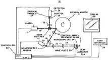
- FIG. 1is a block diagram of a system in accordance with the present invention
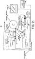
- FIG. 2is a block diagram of another system in accordance with the present invention.
- FIG. 3is a block diagram of a further system in accordance with the present invention.
- System 10includes a first laser 12 (Laser 1 ) for producing light (a laser beam) at an infrared wavelength along a path 13 through beam-splitter 14 onto a rotating polygon mirror 16 .
- Polygon mirror 16has a plurality of mirror facets to reflect the beam from laser 12 at varying angles responsive to the rotation of mirror 16 , i.e., to repeatedly scan the beam.
- the reflected beam from rotating polygon mirror 16travels along a path 17 through relay and focusing lenses 18 and 19 onto a galvanometer mirror 20 .
- Lenses 18 and 19image the beam reflected by the polygon mirror facet onto galvanometer mirror 20 .
- Galvanometer mirror 20reflects the beam incident thereto at a controlled angle through lenses 21 and 22 along a path 23 to an objective focusing lens 24 .
- Lenses 21 and 22image the beam reflected by galvanometer mirror 20 onto objective lens 24 .
- a quarter-wave plate 29is provided in path 23 between lens 22 and objective lens 24 .
- the beam through objective lens 24is then focused at a spot at the confocal image/treatment plane in a tissue of a patient.
- This tissuemay represent any natural or surgically exposed surface of the body of the patent, such as skin, teeth, oral mucosa, cervix, or internal body tissue during surgery.
- the returned reflected light from the tissueis collected by objective lens 24 .
- the reflected lighttravels from objective lens 24 through lenses 22 and 21 to galvanometer mirror 20 .
- Mirror 20reflects the light to rotating polygon mirror 16 via lenses 19 and 18 , and then polygon mirror 16 reflects the light onto beam-splitter 14 .
- Beam-splitter 14reflects the light through lens 26 onto a detector 28 , via a confocal pinhole 27 to produce a confocal image on detector 28 .
- the detectorreceives the scattered light returned from tissue representing the confocal image.
- Detector 28may be a solid-state detector, such as an avalanche photodiode.
- the above described componentsprovide a confocal imaging subsystem in system 10 , and such components may be situated within a confocal head of a microscope.
- the imaging laser beamis linearly polarized
- beam-splitter 14is a polarizing beam-splitter.
- Quarter-wave plate 29is located in path 23 between lenses 22 and 24 for converting specularly reflected light from the tissue to a polarization state orthogonal to the incident illumination of the laser beam to the tissue; this orthogonally polarized light is reflected by beam-splitter 14 to detector 28 .
- a shutter 25may be placed in front of detector 28 to protect detector 28 from possible damage from the light returned from the tissue via beam-splitter 14 .
- Shutter 25may be a mechanical shutter, liquid crystal shutter, absorptive filter, or other type of similar optically protective material or mechanism.
- the rotating polygon mirror 16 and galvanometer mirror 20provide a scanning mechanism in system 10 for scanning the beam of laser 12 in two orthogonal dimensions through the tissue.
- other scanning mechanismsmay be used, such as two galvanometer mirrors which direct the beam of laser 12 along paths 17 and 23 , respectively, holographic or diffractive scanning, or transverse mechanical scanning of objective lens 24 .
- a mechanical actuator stage 24 amay be provided to move objective lens 24 along its optical axis to control the depth of the focused spot in the tissue.
- the scanning mechanism, lenses 18 , 19 , 21 , 22 and 24 , plate 29 , beam-splitter 14 , shutter 25 , and pinhole 27are referred generally to as confocal optics.
- a programmed controller 30controls the operation of system 10 .
- Controller 30can enable laser 12 and control the laser's operating parameters, such as the energy density (or intensity), pulse width, power, duty cycle, and wavelength, of the beam emitted from laser 12 .
- Controller 30also controls the operating (or beam delivery) parameters of the confocal optics, such as the scan rate of the scanning mechanism, depth of focus in the tissue, setting of shutter 25 , and area of illumination (scan width and height), i.e., the field of view of the confocal optics.
- the scanning mechanismis controlled by controller 30 by enabling the rotation of polygon mirror 16 via a motor (not shown), and the angular position of galvanometer mirror 20 .
- the controller 30controls the depth of focus in the tissue of the laser beam by setting the position of the objective lens 24 via actuator stage 24 a .
- the controllermay monitor the position of the scanning mechanism and/or lens 24 during scanning, or direct the scanning mechanism and/or lens 24 to provide the focused spot at a specific position in the tissue.
- the controlleroperates the laser and confocal optics in a visualizing mode where the laser does not damage the tissue, and in a treatment mode to treat the tissue.
- Detector 28provides controller 30 signals representing confocal images. As the scanning mechanism scans the tissue, successive frames of confocal images are provided in real-time to controller 30 from detector 28 .
- the controller 30drives a display 32 to display as a raster scan the confocal images.
- the displayed confocal imageis a two-dimensional digital image composed of an x-y pixel array.
- a user interface 34such as a mouse, keyboard, light pen, or the like, allows an operator to input to controller 30 selected cell or cells (a region of cells) shown on display 32 for subsequent surgical treatment.
- Controller 30is programmed to translate the x-y pixel coordinates of the locations of selected cell or cells on display 32 into terms of the mechanical position of the scanning mechanism of system 10 , i.e., the position of mirrors 20 and 16 when focusing the beam from laser 12 at the locations of such cells.
- the raster scan of the confocal image on display 32is on a time-scale corresponding with the position of scanning through tissue.
- an operatorsuch as a physician, first manually positions the confocal optics of system 10 such that objective lens 24 is placed over the tissue to be treated.
- the confocal opticsare mechanically stabilized to the tissue surface, such as described in U.S. patent application Ser. No. 08/942,431, filed Oct. 1, 1997 by James M. Zavislan.
- the controlleroperates the laser 12 and confocal optics in a visualizing mode at a set of operating parameters (visualizing mode parameters) in which the energy exposure of the tissue to the beam does not damage the tissue.
- the confocal opticsprovide controller 30 , via signals from detector 28 , confocal images of the tissue.
- the confocal imaged section of the tissueappears as a microscopic picture showing surface or subsurface cells of the tissue.
- the operatorcan adjust the depth of the tissue being imaged by fixing the position of objective lens 24 and then moving the tissue, or by restraining the tissue and moving the objective lens 24 along its optical axis via actuator 24 a . In this manner, the operator visualizes the tissue to identify the nominal tissue area to be treated.
- a histological signatureis a spatial or spectral characteristic which identifies the cells in the displayed image.
- Spectral characteristicsrefer to fluorescent or absorptive features of the cells in the displayed image, such as a melanocyte which appears fluorescent in dermal tissue.
- Spatial characteristicsrefer to the specific geometry or orientation of cells, such as, for example, nucleus to cytoplasm area ratio, the shape of melanocytic dendrites, or birefringence of tissue structures.
- Controller 30translates those selected cell or cells in terms of the position of the scanning mechanism when focusing the beam from laser 12 at locations of such cells.
- the usermay also select via interface 34 the set of operating parameters of laser 12 and the confocal optics (treatment mode parameters) during a treatment mode to provide the desired energy exposure of the tissue to effect surgical treatment.
- the set of operating parameters of laser 12 and the confocal opticstreatment mode parameters
- the time of the laser at each selected locationcan be increased or decreased during treatment.
- the operating parameters of the confocal opticsmay be the same for both treatment and visualizing modes.
- System 10can perform at each selected location either localized or non-localized treatment of tissue depending on the treatment mode parameters and the concentration or distribution of laser energy exposure to the tissue.
- Energy exposureis defined as the product of the laser power and the average time at a selected location in the tissue.
- laser 12 and the confocal opticsconcentrate the energy or optical effect to a specific targeted small region of tissue that generally includes the selected cell or cells. This small region may be a volume of tissue of approximately 20 micrometers by 20 micrometers by 20 micrometers or less.
- the wavelength of the laser beam during treatment modeshould be chosen to provide concentration of energy at the desired depth of treatment in the tissue.
- the wavelength of the laser beam during treatment modeshould be chosen which can selectively heat or ablate the tissue, photo-chemically or photo-mechanically effect the issue, or photo-activate a drug in the tissue. Such localized treatment is described later in more detail.
- laser 12 and the confocal opticsdistribute the energy or optical effect over a region of tissue greater than the small subregion that generally includes the selected cell or cells. This region thus includes the cells surrounding the selected cell or cells. Such surrounding cells may or not be confocally imaged.
- Non-localized treatmentis useful where the selected cells define a histological marker of a larger region desired to be treated.
- the wavelength of laser 12 and the focus of the beamshould be chosen during treatment mode to distribute treatment to the region, which may or may not be within the field of view of the confocal optics. Distribution of the laser energy over the region of tissue may by either a single laser shot for gross treatment (such as coagulation) of the tissue region, or multiple laser shots at several locations within the region.
- the operation of laser 12is modulated by controller 30 between its visualizing and treatment mode parameters during a scan to implement localized or non-localized treatment at the selected locations.
- the operation of the confocal opticsmay be either modulated between their visualizing and treatment mode parameters, or maintained constant during a scan at their treatment mode parameters.
- controller 30operates the laser and the confocal optics at the treatment mode parameters when the scanning mechanism locates the focused spot at such positions associated with the selected cell or cells, but at all other times operates the laser and confocal optics at the visualizing mode parameters which do not cause tissue damage.
- treatmentmay occur at selected locations over multiple scans. The increased energy exposure of the tissue at the selected locations may cause a thermal effect on the selected cells, such as thermolysis.
- controller 30may operate shutter 25 to protect detector 28 when beam-splitter 14 reflects sufficiently at the wavelength of the treating laser beam such that excessive power is received in light at detector 28 .
- the operatormay simultaneously view the tissue during treatment on display 32 or sequentially between treatments at different locations in the tissue.
- the operatorviews confocal images of the treated tissue on display 34 to determine the effectiveness of the localized or non-localized treatment.
- the selected cell or cellsserve as a marker for treatment in the treated region of tissue. If the treatment was not sufficiently effective, i.e., the tissue received an insufficient energy exposure, the operator can repeat the treatment at the same or different treatment mode parameters, such as increasing the energy density of laser 12 . If the operator determines that the treatment was effective, the operator may select another area of tissue for treatment.
- system 10allows an operator to select individual cells or groups of cells for localized or non-localized treatment in the layers of the epithelia, supporting stroma, or in capillaries flowing through the skin.
- basal cells, squamous cells, melanocytes, or collagencan be treated.
- confocal images of the skincan show individual cells in blood moving through capillaries. As cells move through a capillary, they can individually be selected by the operator and treated.
- controller 34may be programmed to identify histological signatures of cell or cells, automatically select such cell or cells for treatment, and then treats the cells in the manner so described.
- System 10may effect localized surgical treatment of tissue by operating laser 12 at an energy density and wavelength sufficient to cause photo-chemical changes or photolysis.
- laser 12may be operated in a mode to provide two-photon treatment by emitting high energy femtosecond laser pulses.
- Such laser pulsescause second-order light effects (two-photon) at selected cell or cells which effect treatment by destroying the cells.
- This destructive cellular effectis described in “Cellular response to near-infrared femtosecond laser pulses in two-photon microscopes” by König, et al., Optics Letters, Vol. 22, No. 2, Jan. 15, 1997.
- System 40is identical with system 10 , except that another laser 42 is used to implement treatment instead of laser 12 .
- controller 30 in system 40preferably, in conjunction with the confocal optics, operates laser 12 only at operating parameters (i.e., its visualizing mode parameters) which do not cause damage to the tissue.
- Laser 42provide light (a laser beam) at either the same wavelength as laser 12 during treatment or a different wavelength.
- the wavelength of laser 42may be from the extreme ultraviolet to the infrared, 192 nanometers to 10.6 micrometers.
- the refractive objective lens 24 and other lenses of the confocal opticsmay be replaced by optical elements which operate in this wavelength range, such as reflective surface or transmissive refractive materials at both the treatment beam (from laser 42 ) and the visualizing beam (from laser 12 ) wavelengths.
- the beam from laser 42 when enabledis reflected by a beam-splitter 44 through the confocal optics coaxially with the beam from laser 12 , and the beam from laser 12 when enabled passes through beam-splitter 44 along path 13 .
- controller 30can enable laser 42 and control the laser's operating parameters.
- the focused spot of the beam from laser 42forms in the vicinity of the focused spot of the beam from laser 12 in the tissue.
- system 40The operation of system 40 is the same as that of system 10 for producing confocal images and for selecting and treating tissue, except that controller 30 instead of operating laser 12 to effect localized or non-localized treatment of tissue, operates laser 42 as to effect such treatment.
- System 50is identical to system 10 , except that another laser 52 is used to implement treatment instead of laser 12 .
- Controller 30 in system 50preferably, in conjunction with the confocal optics, operates laser 12 only at operating parameters (i.e., its visualizing mode parameters) which do not cause damage to the tissue.
- Laser 52provide light (a laser beam) at either the same wavelength as laser 12 during treatment or a different wavelength.
- the wavelength of laser 52may be from the extreme ultraviolet to the infrared, 192 nanometers to 10.6 micrometers.
- the refractive objective lens 24 and other lenses of the confocal opticsmay be replaced by optical elements which operate in this wavelength range, such as reflective surface or transmissive refractive materials at both the treatment beam (from laser 52 ) and the visualizing beam (from laser 12 ) wavelengths.
- Two galvanometer mirrors 54 and 56provide a scanning mechanism for the beam from laser 52 .
- Relay and focusing lenses 58 and 59are located in the path of the beam reflected from mirror 54 to image the light from mirror 54 onto mirror 56 .
- Relay and focusing lens 60 and 61are located in the path of the beam reflected from mirror 56 to image the light from mirror 56 onto a beam-splitter 62 .
- Beam-splitter 62reflects the beam from mirror 56 coaxially with the path of the beam from laser 12 through the confocal optics, i.e., objective lens 24 .
- controller 30can enable laser 52 and control the laser's operating parameters.
- the focused spot of the beam from laser 52forms in the vicinity of the focused spot of the beam from laser 12 in the tissue.
- Laser 52 , mirror 54 and 56 , lenses 58 – 61 , and beam-splitter 62 , and objective lens 24provides a treatment subsystem in system 40 controlled by controller 30 .
- system 50operates the same as system 10 for producing confocal images and for selecting and treating tissue, except: After the operator has selected the cell or cells to be surgically treated, controller 30 translates the x-y position of the cells on display 32 in terms of the positions of mirrors 54 and 56 . Mirror 54 and 56 then are positioned to selectively project the beam from laser 52 at the location of such selected cell or cells, while laser 52 is operated by controller 30 at treatment mode parameters to effect treatment.
- Both systems 40 or 50may be operated to provide the same localized and non-localized treatment as discussed in system 10 using their respective lasers 42 or 52 .
- systems 40 and 50can provide localized photo-drug activation of selected confocally imaged cells in which lasers 42 or 52 , respectively, are at operating parameters (wavelength) during treatment which photoactivate a photo-dynamic drug present in such cells.
- This drugis non-active when introduced into the patient prior to treatment, but activated in tissue by the treating laser beam.
- photo-dynamic drugsare often used in certain cancer therapy.
- the activation by the treating laser beammay also be done by the two-photon process, as described above.
- Systems 10 , 40 or 50may be used to perform ablation on confocally imaged areas on the surface of skin, such as in the removal of dermal plaque or basal cell carcinoma. These systems may interatively treat surface tissue to successively remove portions of the plaque until the plaque has been entirely ablated. Between each iteration, the skin surface is confocally imaged on display 32 to determine the location of the next treatment.
- their respective treating lasers 42 or 52provide a laser beam which is absorptive.
- Lasers 42 or 52may be an excimer, holmium, erbium or CO 2 laser.
- laser 12 to effect treatmentmay be operated at a high peak power.
- systems 10 , 40 or 50may be used to perform localized selective thermolysis in which the laser beam effecting treatment operates at a wavelength which is selectively absorbed by certain chromophors of selected cell or cells in the confocally imaged tissue, but only nominally absorbed, i.e., non-damaging, to surrounding cells.
- energy of the treating beamis localized to the cells to be treated.
- Localized selective thermolysis by a laseris described in the publication by Jeffrey Dover and Kenneth Arndt,“Illustrated Cutaneous Laser Surgery, A Practitioner's Guide,” Appleton and Lange, Norwalk, Conn. (1990), page 17.
- Absent controller 30 , display 32 and user interface 34 , systems 10 , 40 or 50may be adapted to be hand-held by an operator.
Landscapes
- Physics & Mathematics (AREA)
- Health & Medical Sciences (AREA)
- Optics & Photonics (AREA)
- Surgery (AREA)
- General Health & Medical Sciences (AREA)
- General Physics & Mathematics (AREA)
- Analytical Chemistry (AREA)
- Chemical & Material Sciences (AREA)
- Life Sciences & Earth Sciences (AREA)
- Otolaryngology (AREA)
- Nuclear Medicine, Radiotherapy & Molecular Imaging (AREA)
- Heart & Thoracic Surgery (AREA)
- Medical Informatics (AREA)
- Molecular Biology (AREA)
- Animal Behavior & Ethology (AREA)
- Engineering & Computer Science (AREA)
- Public Health (AREA)
- Veterinary Medicine (AREA)
- Biomedical Technology (AREA)
- Electromagnetism (AREA)
- Ophthalmology & Optometry (AREA)
- Radiology & Medical Imaging (AREA)
- Microscoopes, Condenser (AREA)
- Laser Surgery Devices (AREA)
- Radiation-Therapy Devices (AREA)
- Investigating, Analyzing Materials By Fluorescence Or Luminescence (AREA)
Abstract
Description
Claims (7)
Priority Applications (1)
| Application Number | Priority Date | Filing Date | Title |
|---|---|---|---|
| US10/698,294US7190990B2 (en) | 1997-03-19 | 2003-10-31 | Cellular surgery utilizing confocal microscopy |
Applications Claiming Priority (4)
| Application Number | Priority Date | Filing Date | Title |
|---|---|---|---|
| US4105097P | 1997-03-19 | 1997-03-19 | |
| US09/044,355US5995867A (en) | 1997-03-19 | 1998-03-19 | Cellular surgery utilizing confocal microscopy |
| US09/438,065US6668186B1 (en) | 1997-03-19 | 1999-11-10 | Cellular surgery utilizing confocal microscopy |
| US10/698,294US7190990B2 (en) | 1997-03-19 | 2003-10-31 | Cellular surgery utilizing confocal microscopy |
Related Parent Applications (1)
| Application Number | Title | Priority Date | Filing Date |
|---|---|---|---|
| US09/438,065DivisionUS6668186B1 (en) | 1997-03-19 | 1999-11-10 | Cellular surgery utilizing confocal microscopy |
Publications (2)
| Publication Number | Publication Date |
|---|---|
| US20040092827A1 US20040092827A1 (en) | 2004-05-13 |
| US7190990B2true US7190990B2 (en) | 2007-03-13 |
Family
ID=21914455
Family Applications (3)
| Application Number | Title | Priority Date | Filing Date |
|---|---|---|---|
| US09/044,355Expired - LifetimeUS5995867A (en) | 1997-03-19 | 1998-03-19 | Cellular surgery utilizing confocal microscopy |
| US09/438,065Expired - LifetimeUS6668186B1 (en) | 1997-03-19 | 1999-11-10 | Cellular surgery utilizing confocal microscopy |
| US10/698,294Expired - Fee RelatedUS7190990B2 (en) | 1997-03-19 | 2003-10-31 | Cellular surgery utilizing confocal microscopy |
Family Applications Before (2)
| Application Number | Title | Priority Date | Filing Date |
|---|---|---|---|
| US09/044,355Expired - LifetimeUS5995867A (en) | 1997-03-19 | 1998-03-19 | Cellular surgery utilizing confocal microscopy |
| US09/438,065Expired - LifetimeUS6668186B1 (en) | 1997-03-19 | 1999-11-10 | Cellular surgery utilizing confocal microscopy |
Country Status (8)
| Country | Link |
|---|---|
| US (3) | US5995867A (en) |
| EP (1) | EP1003429B1 (en) |
| JP (1) | JP4383545B2 (en) |
| AT (1) | ATE409005T1 (en) |
| AU (1) | AU6569198A (en) |
| DE (1) | DE69840046D1 (en) |
| ES (1) | ES2313745T3 (en) |
| WO (1) | WO1998041158A1 (en) |
Cited By (6)
| Publication number | Priority date | Publication date | Assignee | Title |
|---|---|---|---|---|
| US20120026417A1 (en)* | 2009-04-17 | 2012-02-02 | Sony Corporation | Imaging device |
| US8260401B2 (en) | 2006-07-26 | 2012-09-04 | University Of Rochester | Non-invasive in-vivo imaging of mechanoreceptors in skin using confocal microscopy |
| US8620409B2 (en) | 2008-08-04 | 2013-12-31 | University Of Utah Research Foundation | Dye application for confocal imaging of cellular microstructure |
| US9677869B2 (en) | 2012-12-05 | 2017-06-13 | Perimeter Medical Imaging, Inc. | System and method for generating a wide-field OCT image of a portion of a sample |
| CN107096997A (en)* | 2017-05-10 | 2017-08-29 | 华中科技大学 | A kind of three-dimensional microstructures based on continuous laser inscribe system and method |
| US10577573B2 (en) | 2017-07-18 | 2020-03-03 | Perimeter Medical Imaging, Inc. | Sample container for stabilizing and aligning excised biological tissue samples for ex vivo analysis |
Families Citing this family (64)
| Publication number | Priority date | Publication date | Assignee | Title |
|---|---|---|---|---|
| US6745067B1 (en) | 1998-09-14 | 2004-06-01 | Lucid, Inc. | System for marking the locations of imaged tissue with respect to the surface of the tissue |
| US6517532B1 (en) | 1997-05-15 | 2003-02-11 | Palomar Medical Technologies, Inc. | Light energy delivery head |
| ATE409005T1 (en)* | 1997-03-19 | 2008-10-15 | Lucid Inc | CELL SURGERY USING CONFOCAL MICROSCOPY |
| ES2226133T3 (en) | 1997-05-15 | 2005-03-16 | Palomar Medical Technologies, Inc. | DERMATOLOGICAL TREATMENT DEVICE. |
| WO2000053261A1 (en)* | 1999-03-08 | 2000-09-14 | Asah Medico A/S | An apparatus for tissue treatment and having a monitor for display of tissue features |
| JP3554760B2 (en)* | 1997-12-12 | 2004-08-18 | 横河電機株式会社 | Confocal microscope |
| EP1066488A1 (en)* | 1998-02-26 | 2001-01-10 | Lucid, Inc. | Confocal microscope for facilitating cryosurgery of tissue |
| ES2245506T3 (en) | 1998-03-12 | 2006-01-01 | Palomar Medical Technologies, Inc. | ELECTROMAGNETIC RADIATION APPLICATION SYSTEM ON SKIN. |
| JP2002524780A (en)* | 1998-09-14 | 2002-08-06 | ルーシド インコーポレーテッド | Surgical biopsy imaging method |
| US7227630B1 (en) | 1998-09-14 | 2007-06-05 | Lucid, Inc. | Imaging of surgical biopsies |
| US6352502B1 (en)* | 1998-12-03 | 2002-03-05 | Lightouch Medical, Inc. | Methods for obtaining enhanced spectroscopic information from living tissue, noninvasive assessment of skin condition and detection of skin abnormalities |
| US6522407B2 (en) | 1999-01-22 | 2003-02-18 | The Regents Of The University Of California | Optical detection dental disease using polarized light |
| WO2000055669A1 (en)* | 1999-03-18 | 2000-09-21 | Lucid, Inc. | System and method for enhancing confocal reflectance images of tissue specimens |
| US6720547B1 (en)* | 1999-03-18 | 2004-04-13 | Lucid, Inc. | System and method for enhancing confocal reflectance images of tissue specimens |
| EP1087716B1 (en)* | 1999-04-14 | 2005-10-19 | Koninklijke Philips Electronics N.V. | Hair-removing device with a controllable laser source |
| WO2000069333A1 (en)* | 1999-05-19 | 2000-11-23 | The Regents Of The University Of California | Optical detection of dental disease using polarized light |
| US6494878B1 (en)* | 2000-05-12 | 2002-12-17 | Ceramoptec Industries, Inc. | System and method for accurate optical treatment of an eye's fundus |
| DE10024404A1 (en)* | 2000-05-19 | 2001-11-22 | Leica Microsystems | Confocal optical scanning microscopy produces signals influencing object and initiating measurement in accordance with given scanning locations |
| US6450949B1 (en) | 2000-06-30 | 2002-09-17 | Inner Vision Imaging, Inc. | Endoscope |
| US6613042B1 (en)* | 2000-06-30 | 2003-09-02 | Nikolai Tankovich | Rainbow laser |
| US6530882B1 (en)* | 2000-06-30 | 2003-03-11 | Inner Vision Imaging, L.L.C. | Endoscope having microscopic and macroscopic magnification |
| AU7189801A (en)* | 2000-07-07 | 2002-01-21 | Bristol Myers Squibb Co | Electrophysiology configuration suitable for high throughput screening of compounds for drug discovery |
| US7359748B1 (en)* | 2000-07-26 | 2008-04-15 | Rhett Drugge | Apparatus for total immersion photography |
| US7321394B1 (en) | 2000-09-29 | 2008-01-22 | Lucid, Inc. | Automatic gain control for a confocal imaging system |
| US7003345B1 (en) | 2000-10-17 | 2006-02-21 | Lucid, Inc. | System and method for enhancing microscope images of tissue using citric acid and agents of the like |
| US7139122B1 (en)* | 2000-10-17 | 2006-11-21 | Lucid, Inc. | System and method for enhancing confocal reflectance images of tissue specimens |
| JP4685229B2 (en)* | 2000-10-31 | 2011-05-18 | オリンパス株式会社 | Laser microscope |
| EP2314246A1 (en)* | 2001-05-23 | 2011-04-27 | Palomar Medical Technologies, Inc. | Cooling system for a photocosmetic device |
| US6687035B2 (en)* | 2001-06-07 | 2004-02-03 | Leica Microsystems Heildelberg Gmbh | Method and apparatus for ROI-scan with high temporal resolution |
| FR2834349B1 (en)* | 2001-12-28 | 2004-04-09 | Mauna Kea Technologies | CONFOCAL IMAGING APPARATUS ESPECIALLY FOR ENDOSCOPES |
| US7721743B2 (en)* | 2002-01-10 | 2010-05-25 | Katana Technologies Gmbh | Device and procedure for refractive laser surgery |
| WO2003068064A1 (en)* | 2002-02-12 | 2003-08-21 | Science & Engineering Associates, Inc. | Cancer detection and adaptive dose optimization treatment system |
| US20040133112A1 (en)* | 2002-03-08 | 2004-07-08 | Milind Rajadhyaksha | System and method for macroscopic and confocal imaging of tissue |
| WO2004000098A2 (en) | 2002-06-19 | 2003-12-31 | Palomar Medical Technologies, Inc. | Method and apparatus for treatment of cutaneous and subcutaneous conditions |
| EP2522294A2 (en) | 2002-10-23 | 2012-11-14 | Palomar Medical Technologies, Inc. | Phototreatment device for use with coolants and topical substances |
| CN102135661B (en)* | 2003-05-20 | 2014-06-04 | 卢西德有限公司 | Confocal microscope for imaging of selected locations of the body of a patient |
| JP3803673B2 (en)* | 2004-02-02 | 2006-08-02 | オリンパス株式会社 | Measuring method and measuring device |
| US7792570B2 (en)* | 2004-04-07 | 2010-09-07 | Northeastern University | Opto-acoustic signal detection with coherent confocal microscopy |
| EP1737373B1 (en)* | 2004-04-15 | 2010-09-22 | Koninklijke Philips Electronics N.V. | A device for the treatment of skin by means of a radiation beam |
| CN100471464C (en)* | 2004-10-05 | 2009-03-25 | 皇家飞利浦电子股份有限公司 | Skin treatment equipment with radiation emission protection |
| US7856985B2 (en) | 2005-04-22 | 2010-12-28 | Cynosure, Inc. | Method of treatment body tissue using a non-uniform laser beam |
| WO2006124800A2 (en) | 2005-05-12 | 2006-11-23 | Lucid, Inc. | Confocal scanning microscope having optical and scanning systems which provide a handheld imaging head |
| FI118937B (en)* | 2005-07-13 | 2008-05-15 | Picodeon Ltd Oy | diode Pump |
| WO2007006850A2 (en)* | 2005-07-13 | 2007-01-18 | Picodeon Ltd Oy | Radiation arrangement |
| US20070021807A1 (en)* | 2005-07-20 | 2007-01-25 | Eastman Kodak Company | Device for optically stimulating collagen formation in tissue |
| JP2007029603A (en) | 2005-07-29 | 2007-02-08 | Fujinon Corp | Optical diagnostic treatment apparatus |
| CN101309631A (en) | 2005-09-15 | 2008-11-19 | 帕洛玛医疗技术公司 | Skin optical characterization device |
| US7864996B2 (en)* | 2006-02-17 | 2011-01-04 | Lucid, Inc. | System for macroscopic and confocal imaging of tissue |
| US7586957B2 (en) | 2006-08-02 | 2009-09-08 | Cynosure, Inc | Picosecond laser apparatus and methods for its operation and use |
| WO2009094451A2 (en)* | 2008-01-22 | 2009-07-30 | Board Of Regents, The University Of Texas System | Systems, devices and methods for imaging and surgery |
| CA3194784A1 (en) | 2008-05-20 | 2009-11-26 | University Health Network | Device and method for fluorescence-based imaging and monitoring |
| WO2010146588A2 (en)* | 2009-06-16 | 2010-12-23 | Technion- Research And Development Foundation Ltd. | Miniature disease diagnostic system |
| US9919168B2 (en) | 2009-07-23 | 2018-03-20 | Palomar Medical Technologies, Inc. | Method for improvement of cellulite appearance |
| JP5452180B2 (en) | 2009-11-13 | 2014-03-26 | オリンパス株式会社 | Microscope equipment |
| US9333036B2 (en) | 2010-01-22 | 2016-05-10 | Board Of Regents, The University Of Texas System | Systems, devices and methods for imaging and surgery |
| ES2878548T3 (en) | 2012-02-26 | 2021-11-19 | Caliber Imaging & Diagnostics Inc | Tissue specimen stage for an optical sectioning microscope |
| EP2839552A4 (en) | 2012-04-18 | 2015-12-30 | Cynosure Inc | PICOSECOND LASER APPARATUS AND METHOD OF PROCESSING TARGET TISSUES USING THE SAME |
| US9709791B2 (en) | 2012-08-15 | 2017-07-18 | Lucid, Inc. | Systems and methods for imaging tissue |
| US20140272767A1 (en)* | 2013-03-15 | 2014-09-18 | Convergent Dental, Inc. | System and method for optical imaging, magnification, fluorescence, and reflectance |
| US10285757B2 (en) | 2013-03-15 | 2019-05-14 | Cynosure, Llc | Picosecond optical radiation systems and methods of use |
| JP6769949B2 (en) | 2014-07-24 | 2020-10-14 | ユニバーシティー ヘルス ネットワーク | Data collection and analysis for diagnostic purposes |
| WO2019165426A1 (en) | 2018-02-26 | 2019-08-29 | Cynosure, Inc. | Q-switched cavity dumped sub-nanosecond laser |
| US11280990B2 (en) | 2018-02-26 | 2022-03-22 | Caliber Imaging & Diagnostics, Inc. | System and method for macroscopic and microscopic imaging ex-vivo tissue |
| AU2019288652B2 (en)* | 2018-06-22 | 2023-06-08 | Avava, Inc. | Feedback detection for a treatment device |
Citations (25)
| Publication number | Priority date | Publication date | Assignee | Title |
|---|---|---|---|---|
| US4408602A (en) | 1981-01-14 | 1983-10-11 | Asahi Kogaku Kogyo Kabushiki Kaisha | Laser knife device |
| US5034613A (en) | 1989-11-14 | 1991-07-23 | Cornell Research Foundation, Inc. | Two-photon laser microscopy |
| US5035693A (en) | 1987-03-16 | 1991-07-30 | Michael Kratzer | Device for selective destruction of cells |
| US5065008A (en) | 1989-10-18 | 1991-11-12 | Fuji Photo Film Co., Ltd. | Scanning microscope and scanning mechanism for the same |
| US5089384A (en) | 1988-11-04 | 1992-02-18 | Amoco Corporation | Method and apparatus for selective cell destruction using amplified immunofluorescence |
| US5200838A (en) | 1988-05-27 | 1993-04-06 | The University Of Connecticut | Lateral effect imaging system |
| US5364390A (en) | 1988-05-19 | 1994-11-15 | Refractive Laser Research And Development, Inc. | Handpiece and related apparatus for laser surgery and dentistry |
| WO1995003089A1 (en)* | 1993-07-21 | 1995-02-02 | Lucid Technologies, Inc. | Laser treatment system with electronic visualization |
| US5458594A (en) | 1991-08-28 | 1995-10-17 | Siemens Aktiengesellschaft | Method and apparatus for the treatment of hard biological material, such as hard dental material, using lasers |
| US5493116A (en) | 1993-10-26 | 1996-02-20 | Metrologix, Inc. | Detection system for precision measurements and high resolution inspection of high aspect ratio structures using particle beam devices |
| US5501655A (en) | 1992-03-31 | 1996-03-26 | Massachusetts Institute Of Technology | Apparatus and method for acoustic heat generation and hyperthermia |
| US5582168A (en) | 1991-07-17 | 1996-12-10 | Georgia Tech Research Corp. | Apparatus and methods for measuring characteristics of biological tissues and similar materials |
| US5608519A (en) | 1995-03-20 | 1997-03-04 | Gourley; Paul L. | Laser apparatus and method for microscopic and spectroscopic analysis and processing of biological cells |
| US5632741A (en) | 1995-01-20 | 1997-05-27 | Lucid Technologies, Inc. | Epilation system |
| US5753230A (en) | 1994-03-18 | 1998-05-19 | The Scripps Research Institute | Methods and compositions useful for inhibition of angiogenesis |
| US5760950A (en) | 1996-07-25 | 1998-06-02 | Advanced Scanning, Ltd. | Scanning confocal microscope |
| US5784162A (en) | 1993-08-18 | 1998-07-21 | Applied Spectral Imaging Ltd. | Spectral bio-imaging methods for biological research, medical diagnostics and therapy |
| US5788639A (en) | 1995-07-13 | 1998-08-04 | Lucid Technologies, Inc. | Confocal imaging through thick dermal tissue |
| US5839445A (en)* | 1996-07-25 | 1998-11-24 | Con-S Ltd. | Method of diagnosis of diseases using confocal microscope |
| US5848177A (en) | 1994-12-29 | 1998-12-08 | Board Of Trustees Operating Michigan State University | Method and system for detection of biological materials using fractal dimensions |
| US5995867A (en)* | 1997-03-19 | 1999-11-30 | Lucid Inc | Cellular surgery utilizing confocal microscopy |
| US5995866A (en) | 1995-03-21 | 1999-11-30 | Lemelson; Jerome | Method and apparatus for scanning and evaluating matter |
| US6042603A (en)* | 1996-10-30 | 2000-03-28 | Photogen, Inc. | Method for improved selectivity in photo-activation of molecular agents |
| US6099522A (en) | 1989-02-06 | 2000-08-08 | Visx Inc. | Automated laser workstation for high precision surgical and industrial interventions |
| US6166385A (en) | 1995-09-19 | 2000-12-26 | Cornell Research Foundation, Inc. | Multi-photon laser microscopy |
Family Cites Families (10)
| Publication number | Priority date | Publication date | Assignee | Title |
|---|---|---|---|---|
| US4289378A (en) | 1978-06-21 | 1981-09-15 | Ernst Remy | Apparatus for adjusting the focal point of an operating laser beam focused by an objective |
| US4395397A (en)* | 1981-09-17 | 1983-07-26 | Sidney Farber Cancer Institute, Inc. | Apparatus and method for killing unwanted cells |
| ITFI940095A1 (en)* | 1994-05-23 | 1995-11-23 | Molteni & C | PHOTODYNAMIC CONJUGATES WITH BIOCIDE PROPERTIES |
| US5795755A (en)* | 1994-07-05 | 1998-08-18 | Lemelson; Jerome H. | Method of implanting living cells by laser poration at selected sites |
| NO180167C (en)* | 1994-09-08 | 1997-02-26 | Photocure As | Photochemical method for introducing molecules into the cytosol of cells |
| WO1996021938A1 (en)* | 1995-01-13 | 1996-07-18 | The General Hospital Corporation | Video-rate confocal scanning laser microscope |
| US6424852B1 (en) | 1996-10-18 | 2002-07-23 | Lucid, Inc. | System for confocal imaging within dermal tissue |
| US5832931A (en)* | 1996-10-30 | 1998-11-10 | Photogen, Inc. | Method for improved selectivity in photo-activation and detection of molecular diagnostic agents |
| US5836877A (en)* | 1997-02-24 | 1998-11-17 | Lucid Inc | System for facilitating pathological examination of a lesion in tissue |
| US5874266A (en)* | 1997-03-27 | 1999-02-23 | Palsson; Bernhard O. | Targeted system for removing tumor cells from cell populations |
- 1998
- 1998-03-19ATAT98911824Tpatent/ATE409005T1/ennot_activeIP Right Cessation
- 1998-03-19JPJP54079498Apatent/JP4383545B2/ennot_activeExpired - Fee Related
- 1998-03-19EPEP98911824Apatent/EP1003429B1/ennot_activeExpired - Lifetime
- 1998-03-19USUS09/044,355patent/US5995867A/ennot_activeExpired - Lifetime
- 1998-03-19WOPCT/US1998/005399patent/WO1998041158A1/enactiveApplication Filing
- 1998-03-19ESES98911824Tpatent/ES2313745T3/ennot_activeExpired - Lifetime
- 1998-03-19DEDE69840046Tpatent/DE69840046D1/ennot_activeExpired - Lifetime
- 1998-03-19AUAU65691/98Apatent/AU6569198A/ennot_activeAbandoned
- 1999
- 1999-11-10USUS09/438,065patent/US6668186B1/ennot_activeExpired - Lifetime
- 2003
- 2003-10-31USUS10/698,294patent/US7190990B2/ennot_activeExpired - Fee Related
Patent Citations (27)
| Publication number | Priority date | Publication date | Assignee | Title |
|---|---|---|---|---|
| US4408602A (en) | 1981-01-14 | 1983-10-11 | Asahi Kogaku Kogyo Kabushiki Kaisha | Laser knife device |
| US5035693A (en) | 1987-03-16 | 1991-07-30 | Michael Kratzer | Device for selective destruction of cells |
| US5364390A (en) | 1988-05-19 | 1994-11-15 | Refractive Laser Research And Development, Inc. | Handpiece and related apparatus for laser surgery and dentistry |
| US5200838A (en) | 1988-05-27 | 1993-04-06 | The University Of Connecticut | Lateral effect imaging system |
| US5089384A (en) | 1988-11-04 | 1992-02-18 | Amoco Corporation | Method and apparatus for selective cell destruction using amplified immunofluorescence |
| US6099522A (en) | 1989-02-06 | 2000-08-08 | Visx Inc. | Automated laser workstation for high precision surgical and industrial interventions |
| US5065008A (en) | 1989-10-18 | 1991-11-12 | Fuji Photo Film Co., Ltd. | Scanning microscope and scanning mechanism for the same |
| US5034613A (en) | 1989-11-14 | 1991-07-23 | Cornell Research Foundation, Inc. | Two-photon laser microscopy |
| US5582168A (en) | 1991-07-17 | 1996-12-10 | Georgia Tech Research Corp. | Apparatus and methods for measuring characteristics of biological tissues and similar materials |
| US5458594A (en) | 1991-08-28 | 1995-10-17 | Siemens Aktiengesellschaft | Method and apparatus for the treatment of hard biological material, such as hard dental material, using lasers |
| US5501655A (en) | 1992-03-31 | 1996-03-26 | Massachusetts Institute Of Technology | Apparatus and method for acoustic heat generation and hyperthermia |
| US5653706A (en) | 1993-07-21 | 1997-08-05 | Lucid Technologies Inc. | Dermatological laser treatment system with electronic visualization of the area being treated |
| WO1995003089A1 (en)* | 1993-07-21 | 1995-02-02 | Lucid Technologies, Inc. | Laser treatment system with electronic visualization |
| US5784162A (en) | 1993-08-18 | 1998-07-21 | Applied Spectral Imaging Ltd. | Spectral bio-imaging methods for biological research, medical diagnostics and therapy |
| US5493116A (en) | 1993-10-26 | 1996-02-20 | Metrologix, Inc. | Detection system for precision measurements and high resolution inspection of high aspect ratio structures using particle beam devices |
| US5753230A (en) | 1994-03-18 | 1998-05-19 | The Scripps Research Institute | Methods and compositions useful for inhibition of angiogenesis |
| US5848177A (en) | 1994-12-29 | 1998-12-08 | Board Of Trustees Operating Michigan State University | Method and system for detection of biological materials using fractal dimensions |
| US5632741A (en) | 1995-01-20 | 1997-05-27 | Lucid Technologies, Inc. | Epilation system |
| US5608519A (en) | 1995-03-20 | 1997-03-04 | Gourley; Paul L. | Laser apparatus and method for microscopic and spectroscopic analysis and processing of biological cells |
| US5995866A (en) | 1995-03-21 | 1999-11-30 | Lemelson; Jerome | Method and apparatus for scanning and evaluating matter |
| US5788639A (en) | 1995-07-13 | 1998-08-04 | Lucid Technologies, Inc. | Confocal imaging through thick dermal tissue |
| US6166385A (en) | 1995-09-19 | 2000-12-26 | Cornell Research Foundation, Inc. | Multi-photon laser microscopy |
| US5839445A (en)* | 1996-07-25 | 1998-11-24 | Con-S Ltd. | Method of diagnosis of diseases using confocal microscope |
| US5760950A (en) | 1996-07-25 | 1998-06-02 | Advanced Scanning, Ltd. | Scanning confocal microscope |
| US6042603A (en)* | 1996-10-30 | 2000-03-28 | Photogen, Inc. | Method for improved selectivity in photo-activation of molecular agents |
| US5995867A (en)* | 1997-03-19 | 1999-11-30 | Lucid Inc | Cellular surgery utilizing confocal microscopy |
| US6668186B1 (en)* | 1997-03-19 | 2003-12-23 | Lucid, Inc. | Cellular surgery utilizing confocal microscopy |
Cited By (9)
| Publication number | Priority date | Publication date | Assignee | Title |
|---|---|---|---|---|
| US8260401B2 (en) | 2006-07-26 | 2012-09-04 | University Of Rochester | Non-invasive in-vivo imaging of mechanoreceptors in skin using confocal microscopy |
| US8620409B2 (en) | 2008-08-04 | 2013-12-31 | University Of Utah Research Foundation | Dye application for confocal imaging of cellular microstructure |
| US20120026417A1 (en)* | 2009-04-17 | 2012-02-02 | Sony Corporation | Imaging device |
| US9677869B2 (en) | 2012-12-05 | 2017-06-13 | Perimeter Medical Imaging, Inc. | System and method for generating a wide-field OCT image of a portion of a sample |
| US10359271B2 (en) | 2012-12-05 | 2019-07-23 | Perimeter Medical Imaging, Inc. | System and method for tissue differentiation in imaging |
| CN107096997A (en)* | 2017-05-10 | 2017-08-29 | 华中科技大学 | A kind of three-dimensional microstructures based on continuous laser inscribe system and method |
| CN107096997B (en)* | 2017-05-10 | 2019-09-24 | 华中科技大学 | A kind of three-dimensional microstructures inscription system and method based on continuous laser |
| US10577573B2 (en) | 2017-07-18 | 2020-03-03 | Perimeter Medical Imaging, Inc. | Sample container for stabilizing and aligning excised biological tissue samples for ex vivo analysis |
| US10894939B2 (en) | 2017-07-18 | 2021-01-19 | Perimeter Medical Imaging, Inc. | Sample container for stabilizing and aligning excised biological tissue samples for ex vivo analysis |
Also Published As
| Publication number | Publication date |
|---|---|
| US6668186B1 (en) | 2003-12-23 |
| EP1003429A1 (en) | 2000-05-31 |
| WO1998041158A1 (en) | 1998-09-24 |
| DE69840046D1 (en) | 2008-11-06 |
| JP2001517119A (en) | 2001-10-02 |
| US5995867A (en) | 1999-11-30 |
| ES2313745T3 (en) | 2009-03-01 |
| EP1003429A4 (en) | 2000-05-31 |
| EP1003429B1 (en) | 2008-09-24 |
| US20040092827A1 (en) | 2004-05-13 |
| ATE409005T1 (en) | 2008-10-15 |
| AU6569198A (en) | 1998-10-12 |
| JP4383545B2 (en) | 2009-12-16 |
Similar Documents
| Publication | Publication Date | Title |
|---|---|---|
| US7190990B2 (en) | Cellular surgery utilizing confocal microscopy | |
| US6676654B1 (en) | Apparatus for tissue treatment and having a monitor for display of tissue features | |
| US7083611B2 (en) | Method and apparatus for providing facial rejuvenation treatments | |
| US5653706A (en) | Dermatological laser treatment system with electronic visualization of the area being treated | |
| US10603215B2 (en) | System and method for determining dosimetry in ophthalmic photomedicine | |
| US6383177B1 (en) | Apparatus for tissue treatment | |
| US6494878B1 (en) | System and method for accurate optical treatment of an eye's fundus | |
| US7220254B2 (en) | Dermatological treatment with visualization | |
| JP4659761B2 (en) | Device for monitoring and controlling tissue treatment with a laser | |
| KR100454522B1 (en) | Laser dermablator and dermablation | |
| US20060253176A1 (en) | Dermatological treatment device with deflector optic | |
| CN112914515A (en) | Measuring device and non-invasive treatment device for skin properties | |
| WO1996021938A1 (en) | Video-rate confocal scanning laser microscope | |
| JP7408906B2 (en) | Diffractive optics for tissue treatment using EMR | |
| RU2181572C2 (en) | Medical laser device | |
| AU2011203543A1 (en) | System and method for determining dosimetry in ophthalmic photomedicine |
Legal Events
| Date | Code | Title | Description |
|---|---|---|---|
| STCF | Information on status: patent grant | Free format text:PATENTED CASE | |
| FPAY | Fee payment | Year of fee payment:4 | |
| SULP | Surcharge for late payment | ||
| AS | Assignment | Owner name:SQUARE 1 BANK, NORTH CAROLINA Free format text:SECURITY AGREEMENT;ASSIGNOR:LUCID, INC.;REEL/FRAME:026795/0600 Effective date:20110720 | |
| AS | Assignment | Owner name:LUCID, INC., NEW YORK Free format text:RELEASE BY SECURED PARTY;ASSIGNOR:SQUARE 1 BANK;REEL/FRAME:028207/0361 Effective date:20120511 | |
| AS | Assignment | Owner name:NORTHEAST LCD CAPITAL, LLC, MAINE Free format text:SECURITY AGREEMENT;ASSIGNOR:LUCID, INC.;REEL/FRAME:028533/0017 Effective date:20120705 | |
| FPAY | Fee payment | Year of fee payment:8 | |
| AS | Assignment | Owner name:LUCID TECHNOLOGIES, INC., NEW YORK Free format text:ASSIGNMENT OF ASSIGNORS INTEREST;ASSIGNORS:ZAVISLAN, JAMES M.;GREENWALD, ROGER J.;REEL/FRAME:037890/0734 Effective date:19980319 | |
| AS | Assignment | Owner name:LUCID, INC., NEW YORK Free format text:CHANGE OF NAME;ASSIGNOR:LUCID TECHNOLOGIES, INC.;REEL/FRAME:038051/0027 Effective date:19980518 | |
| AS | Assignment | Owner name:CALIBER IMAGING & DIAGNOSTICS, INC., NEW YORK Free format text:CHANGE OF NAME;ASSIGNOR:LUCID, INC.;REEL/FRAME:038226/0225 Effective date:20141120 | |
| FEPP | Fee payment procedure | Free format text:MAINTENANCE FEE REMINDER MAILED (ORIGINAL EVENT CODE: REM.); ENTITY STATUS OF PATENT OWNER: SMALL ENTITY | |
| LAPS | Lapse for failure to pay maintenance fees | Free format text:PATENT EXPIRED FOR FAILURE TO PAY MAINTENANCE FEES (ORIGINAL EVENT CODE: EXP.); ENTITY STATUS OF PATENT OWNER: SMALL ENTITY | |
| STCH | Information on status: patent discontinuation | Free format text:PATENT EXPIRED DUE TO NONPAYMENT OF MAINTENANCE FEES UNDER 37 CFR 1.362 | |
| FP | Lapsed due to failure to pay maintenance fee | Effective date:20190313 | |
| AS | Assignment | Owner name:WESTERN ALLIANCE BANK, CALIFORNIA Free format text:SECURITY INTEREST;ASSIGNOR:CALIBER IMAGING & DIAGNOSTICS, INC.;REEL/FRAME:051094/0824 Effective date:20191120 |