US7190775B2 - High quality audio conferencing with adaptive beamforming - Google Patents
High quality audio conferencing with adaptive beamformingDownload PDFInfo
- Publication number
- US7190775B2 US7190775B2US10/697,670US69767003AUS7190775B2US 7190775 B2US7190775 B2US 7190775B2US 69767003 AUS69767003 AUS 69767003AUS 7190775 B2US7190775 B2US 7190775B2
- Authority
- US
- United States
- Prior art keywords
- signal
- conferencing system
- audio conferencing
- microphone
- adaptive beamforming
- Prior art date
- Legal status (The legal status is an assumption and is not a legal conclusion. Google has not performed a legal analysis and makes no representation as to the accuracy of the status listed.)
- Expired - Lifetime, expires
Links
Images


Classifications
- H—ELECTRICITY
- H04—ELECTRIC COMMUNICATION TECHNIQUE
- H04M—TELEPHONIC COMMUNICATION
- H04M9/00—Arrangements for interconnection not involving centralised switching
- H04M9/08—Two-way loud-speaking telephone systems with means for conditioning the signal, e.g. for suppressing echoes for one or both directions of traffic
- H04M9/10—Two-way loud-speaking telephone systems with means for conditioning the signal, e.g. for suppressing echoes for one or both directions of traffic with switching of direction of transmission by voice frequency
- H—ELECTRICITY
- H04—ELECTRIC COMMUNICATION TECHNIQUE
- H04M—TELEPHONIC COMMUNICATION
- H04M9/00—Arrangements for interconnection not involving centralised switching
- H04M9/08—Two-way loud-speaking telephone systems with means for conditioning the signal, e.g. for suppressing echoes for one or both directions of traffic
Definitions
- teleconferencing systemsare commonplace when meetings extend across multiple locations. Attendees typically gather in an office or meeting room and are seated at various locations about the room. The room used for the teleconference is typically not equipped with special sound tailoring materials, and echoes of both near and far-end voices add to the noise level. If the room is large enough, some attendees may be seated away from the conference table, distancing themselves from the microphones. Some of the attendees may not actively participate, or may contribute only occasionally. Their presence, however, adds to the number of sources of room noise as pencil tapping, paper rustling, and side conversations develop. These noise sources further degrade the sound quality experienced by the far-end party.
- the majority of teleconferencing systemshave microphones deployed at one, two, or at most three locations.
- the microphonesare typically positioned on the surface of a conference table, distributed in a manner that provides the best pickup of the most significant contributors to the meeting. This selection of microphone positions may make some of the contributors difficult to hear. Occasional participants are frequently forced to move closer to a microphone when they speak, creating additional room noise as they switch seats or move chairs.
- an audio conferencing systemcomprising at least one loudspeaker for converting a first electrical signal into sound, a plurality of conference stations in spaced relation, and a signal processor.
- Each of the plurality of conference stationsmay comprise a directional microphone for converting sound into a directional microphone signal, and the directional microphone signals may collectively form a plurality of directional microphone signals.
- the signal processormay modify at least one of the plurality of directional microphone signals and a receive signal, and may produce at least one of a transmit signal and the first electrical signal.
- the modifyingmay comprise an algorithm to perform acoustic echo cancellation, and the modifying may also comprise an adaptive beamforming technique.
- the adaptive beamforming techniquemay comprise at least one of a normalized least mean squares algorithm and a recursive least squares algorithm.
- the modifyingmay combine the plurality of directional microphone signals in order to selectively attenuate or amplify a sound source.
- the modifyingmay select for separate processing at least two groups of directional microphone signals from the plurality of directional microphone signals.
- the modifying of each of the at least two groupsmay use an adaptive beamforming technique.
- An embodiment of the present inventionmay also comprise at least one omni-directional microphone for converting a sound field into an omni-directional microphone signal.
- the modifying in such an embodimentmay comprise combining at least one of the plurality of directional microphone signals and the at least one omni-directional microphone signal, based upon at least one room condition.
- the at least one room conditionmay comprise at least one of background noise, a level of acoustic echo, and the detection of side conversations.
- each of the conference stationsmay comprise a transducer for producing an acoustic test signal, and the signal processor may use a test signal to determine at least one of microphone and room acoustic characteristics.
- the contribution to the transmit signal of a selected sound source relative to other sound sourcesmay be increased or decreased from a location remote from the audio conferencing system.
- An embodiment of the present inventionmay comprise an interface compatible with a communication network, and the interface may couple the transmit signal to the communication network, and the communication network to the receive signal.
- the communication networkmay be a packet network.
- An embodiment in accordance with the present inventionmay also comprise a manual input device used for at least one of controlling calls and entering system parameters, and the signal processor may be a digital signal processor.
- Such a methodmay comprise receiving a first electrical signal, and transducing each of a plurality of sound fields into a microphone signal.
- the microphone signalsmay collectively form a plurality of microphone signals.
- the methodmay also comprise processing at least one of the plurality of microphone signals and the first electrical signal to produce a second electrical signal, and transmitting the second electrical signal.
- the processingmay comprise an algorithm to perform acoustic echo cancellation, and the processing may comprise an adaptive beamforming technique.
- the adaptive beamforming techniquemay comprise at least one of a normalized least mean squares algorithm and a recursive least squares algorithm.
- the processingmay also comprise selecting at least two groups of microphone signals from the plurality of microphone signals, and each of the at least two groups of microphone signals may be used in a separate adaptive beamforming arrangement.
- the processingmay use at least one parameter representative of at least one of a microphone acoustic characteristic, a transmission delay, and an acoustic characteristic of a room.
- the processingmay be modified remotely during operation, and the processing may be performed using a digital signal processor.
- At least one of the first electrical signal and the second electrical signalmay be a digital signal, and at least one of the first electrical signal and the second electrical signal may be compliant with a packet protocol.
- Another embodiment of the present inventionmay comprise generating a first electrical test signal, converting the first electrical test signal to an acoustic test signal at a first location, sampling the acoustic test signal at a second location, transforming the sampled acoustic test signal into a second electrical test signal, and deriving at least one of a microphone acoustic characteristic, a transmission delay, and an acoustic characteristic of a room using the second electrical test signal.
- a method in accordance with the present inventionmay comprise receiving a plurality of microphone signals, selecting at least two groups of microphone signals from the plurality of microphone signals, and processing each of the at least two groups of microphone signals using an adaptive beamforming technique. The processing may produce an output signal for each of the at least two groups of microphone signals, and may combine the output signals.
- An embodiment of the present inventionmay also comprise performing acoustic echo cancellation on at least a portion of the plurality of microphone signals.
- the selectingmay be based upon at least one of an amplitude of a microphone signal, a propagation delay, and an input from a user, and the adaptive beamforming technique may comprise at least one of a normalized least mean squares algorithm and a recursive least squares algorithm.
- FIG. 1is a block diagram showing an overhead view of an exemplary audio teleconferencing environment comprising a conference room, a conference table surrounded by conference attendees, a loudspeaker, and a group of spatially dispersed microphones, in accordance with an embodiment of the present invention.
- FIG. 2Ais a block diagram illustrating three adaptive beamforming groups in an overhead view of an exemplary audio teleconferencing environment comprising a conference room, a conference table surrounded by conference attendees, a loudspeaker, and a group of spatially dispersed microphones, in accordance with an embodiment of the present invention.
- FIG. 2Bis a block diagram illustrating an overhead view of another exemplary audio teleconferencing environment comprising a conference room, a conference table surrounded by conference attendees, a loudspeaker, a group of spatially dispersed directional microphones, and a number of spatially dispersed omni-directional microphones, in accordance with an embodiment of the present invention.
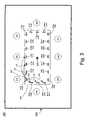
- FIG. 3is a block diagram showing an overhead view of another exemplary audio teleconferencing environment comprising a conference room, a conference table surrounded by conference attendees, a loudspeaker, and a number of conference stations, in accordance with an embodiment of the present invention.
- FIG. 4is a block diagram of an exemplary embodiment of an audio teleconferencing system supporting adaptive beamforming, in accordance with an embodiment of the present invention.
- FIG. 5is a block diagram of another exemplary embodiment of an audio teleconferencing system supporting adaptive beamforming, in accordance with an embodiment of the present invention.
- FIG. 6is a flowchart of an exemplary method of operating a high-quality audio conferencing system with adaptive beamforming, in accordance with an embodiment of the present invention.
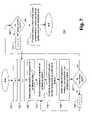
- FIG. 7is a flowchart of an exemplary method of deriving audio conference system and conference room acoustic characteristics in an audio conference system such as the audio conference system illustrated in FIG. 5 , in accordance with an embodiment of the present invention.
- aspects of the present inventionrelate to audio conferencing systems.
- certain aspects of the present inventionrelate to a system and method for providing high quality audio conferencing using adaptive beamforming techniques.
- FIG. 1is a block diagram showing an overhead view of an exemplary audio teleconferencing environment 100 comprising a conference room 105 , a conference table 107 surrounded by conference attendees 140 – 147 , a loudspeaker 108 , and a group of spatially dispersed microphones 110 – 129 , in accordance with an embodiment of the present invention.
- the microphones 110 – 129may be directional microphones, and may be positioned, for example, at regular intervals along the edges, or just under the lip of the conference table 107 . A spacing of, for example, 6–12 inches may be used between microphones. Although 20 microphones are shown in FIG.
- a greater or lesser number of microphonesmay be used in an embodiment in accordance with the present invention, depending upon the spacing, the dimensions of the conference table 107 , and microphone placement.
- the loudspeaker 108may be a single loudspeaker located near the center of conference table 107 , or it may comprise two or more loudspeakers located in the ceiling above the conference table 107 , or on the walls of the conference room 105 .
- the conference attendees 140 – 147are engaged in an audio teleconferencing session with a far-end party (not shown).
- each attendeemay include, for example, speech, the noise of papers shuffling, the tapping of a pencil, or the movement of feet or furniture.
- Each of these soundstake a number of paths within the conference environment 100 . Each path is either a direct path, by which the sound arrives first at the receiver, or an indirect path in which the sound energy is bounced from surface to surface within the audio teleconferencing environment 100 .
- the shortest, most direct speech path for each participantis of primary interest.
- the speech energy which takes an indirect path, and the other sounds of attendee activity listed aboveare potential sources of noise that may be picked up by the microphones 110 – 129 and transmitted to the far-end teleconference attendees.
- the speech energy from conference participant 147may take a direct path 147 a and/or an indirect path 147 b to microphone 120 .
- the speech energy from loudspeaker 108may take a direct path 108 a and/or an indirect path 108 b to microphone 120 .
- FIG. 1the illustration of FIG. 1 has been simplified for clarity, and that the speech energy from loudspeaker 108 and conference participant 147 will, in all likelihood, travel over a much larger number of indirect paths on its journey to microphone 120 than those illustrated in FIG. 1 .
- Each of the indirect paths, and all but one of the direct paths from a conference participant 140 – 147 and a microphone 110 – 129constitute an additional source of noise in the signals from microphones 110 – 120 .
- the signal received from the far-end conference locationis played back through loudspeaker 108 , and is received by one or more of the microphones 110 – 129 .
- the portion of the far-end signal received by microphones 110 – 129is normally referred to as “acoustic echo”.
- An embodiment of the present inventionmay minimize the acoustic echo in the signals from each of the microphones 110 – 129 before proceeding to combine the microphone signals for transmission to the far-end party.
- the speech signal received from the far-end and played back through loudspeaker 108may be used as a reference signal in the cancellation of the acoustic echo in the signals from microphones 110 – 129 .
- an embodiment in accordance with the present inventionmay combine the signals from one or more groups of microphones selected from, for example, the microphones 110 – 129 of FIG. 1 , in order to implement one or more adaptive beamforming groups.
- the number of adaptive beamforming groups and the number of microphones in each adaptive beamforming groupmay be arranged to enhance the reception of speech signals from a selected set of conference participants 140 – 147 .
- an embodiment of the present inventionmay identify a primary microphone for each of a predetermined number of “dominant” speakers among conference participants 140 – 147 based upon, for example, the power level from each of the microphones 110 – 129 .
- Such an embodimentmay then select one or more neighboring microphones for each of the identified primary microphones.
- Information about the spatial relationship of the microphones 110 – 129may be provided during system installation or setup using, for example, a keypad, a console unit, or a remote control.
- Each of the identified primary microphones and its selected neighboring microphonesform an adaptive beamforming group.
- a combined signal for each adaptive beamforming groupmay be calculated from the sampled, digitized speech of each of the microphones in the adaptive beamforming group.
- Such an embodiment of the present inventionmay use a normalized least mean squares or recursive least squares algorithm to implement an adaptive beamforming arrangement using the spatially-distributed, directional microphones in each of the adaptive beamforming groups.
- the adaptive beamforming algorithm used for the adaptive beamforming group for each dominant speakermay operate independently from that of other adaptive beamforming groups. In this manner, the signals from each of the microphones of an adaptive beamforming group may be combined to minimize contributions of sounds not originating from the dominant speaker for that adaptive beamforming group, and to maximize the signal of the dominant speaker assigned to that beamforming group.
- the processing for the above algorithmsmay be performed, for example, using a digital signal processor.
- the algorithms of the above described arrangementmay compute the power level of the signals from microphones 110 – 129 , and rank order them in decreasing order of signal power.
- the algorithmsmay then select or identify a predetermined number, N, of microphones with the greatest signal power.
- Each one of the identified microphonesmay then be considered to be a “primary” microphone for one of N dominant speakers from conference participants 140 – 147 .
- an embodiment of the present inventionmay select N groups of microphones based upon, for example, the proximity of each microphone to a given primary microphone, coverage pattern of each microphone relative to the coverage pattern of a primary microphone, a combination of the above, including a heuristic-based approach.
- FIG. 2Ais a block diagram illustrating three adaptive beamforming groups 240 a , 242 a , 245 a in an overhead view of an exemplary audio teleconferencing environment 200 comprising a conference room 205 , a conference table 207 surrounded by conference attendees 240 – 247 , a loudspeaker 208 , and a group of spatially dispersed microphones 210 – 229 , in accordance with an embodiment of the present invention.
- the microphones 210 – 229may be directional microphones, and may be positioned, for example, at regular intervals along the edges, or just under the lip of the conference table 207 . A spacing of, for example, 6–12 inches may be used between microphones 210 – 229 .
- adaptive beamforming group 240 acomprises a primary microphone 218 and two neighbor microphones 217 , 219
- adaptive beamforming group 242 acomprises a primary microphone 213 and two neighbor microphones 212 , 214
- adaptive beamforming group 245 acomprises a primary microphone 226 and one neighbor microphone 225 .
- Parameters used in an embodiment of the present inventionmay include the periodicity of identification of the dominant speakers, the algorithm used for the computation of the speech power from microphones 210 – 229 , the maximum number of dominant speakers/adaptive beamforming groups, and criteria used for selection of the neighbor microphones that make up each adaptive beamforming group, to name just a few of the factors.
- the acoustic signals received from the loudspeaker 208 by one or more of the microphones 210 a – 229 aare collectively referred to as “acoustic echo”.
- An embodiment in accordance with the present inventionmay minimize the components of acoustic echo in the signals from each of the microphones 210 – 229 before performing further processing of the microphone signals for transmission to the far-end party.
- the speech signal received from the far-end and played back through loudspeaker 208may be used as a reference signal in the cancellation of the acoustic echo in the signals from the microphones 210 – 229 .
- the signals from each of the microphones of each adaptive beamforming groupmay be combined using, for example, a normalized least mean squares (NLMS) or a recursive least squares (RLS) algorithm. Details concerning the application of the normalized least mean squares and recursive least squares algorithms may be found in “Microphone Arrays”, M. Brandstein and D. Ward, Eds., Springer-Verlag, New York, 2001, and will not be provided here.
- the resulting signals, one for each adaptive beamforming groupmay be further combined before transmission to the intended recipient.
- the number of adaptive beamforming groups included in the transmit signalmay be controlled remotely by the far-end participants using, for example, a key pad, a console device, or a remote control attached to an audio conferencing system.
- a keypadmay be used to increase or decrease the number of participants whose speech audio is included in the signal transmitted to the far end from the near-end audio teleconferencing environment 200 .
- a messagemay also be sent to the near-end audio conferencing system to increase or decrease the relative speech amplitude of an identified adaptive beamforming group corresponding to a particular dominant speaker.
- a far-end conference participantmay include or exclude speakers by increasing or reducing the number of active adaptive beamforming groups, and by adjusting the portion of the total conference audio signal taken from each adaptive beamforming group.
- FIG. 2Bis a block diagram illustrating an overhead view of another exemplary audio teleconferencing environment 250 comprising a conference room 255 , a conference table 257 surrounded by conference attendees 290 – 297 , a loudspeaker 258 , a group of spatially dispersed directional microphones 260 – 279 , and a number of spatially dispersed omni-directional microphones 280 – 283 , in accordance with an embodiment of the present invention.
- the directional microphones 260 – 279may be positioned, for example, at regular intervals along the edges, or just under the lip of the conference table 257 . A spacing of, for example, 6–12 inches may be used between directional microphones 260 – 279 .
- adaptive beamforming group 290 acomprises a primary directional microphone 268 and two neighbor directional microphones 267 , 269
- adaptive beamforming group 292 acomprises a primary directional microphone 263 and two neighbor directional microphones 262 , 264
- adaptive beamforming group 295 acomprises a primary directional microphone 276 and one neighbor directional microphone 275 .
- the identification of the dominant speakers and, therefore, the selection of the primary and neighbor microphones for each dominant speaker in FIG. 2Bmay be periodically re-evaluated, in order to track the dynamics of group interaction.
- Parameters used in an embodiment of the present inventionmay include the periodicity of identification of the dominant speakers, the algorithm used for the computation of the speech power from microphones 260 – 279 , the maximum number of dominant speakers/adaptive beamforming groups, and criteria used for selection of the neighbor microphones that make up each adaptive beamforming group, to name just a few of the factors.
- the acoustic signals received from the loudspeaker 258 by one or more of the directional microphones 260 a – 279 aare collectively referred to as “acoustic echo”.
- An embodiment in accordance with the present inventionmay minimize the components of acoustic echo in the signals from each of the directional microphones 260 – 279 before performing further processing of the microphone signals for transmission to the far-end party. Cancellation of acoustic echo may also be applied to the signals from the omni-directional microphones 280 – 283 .
- the speech signal received from the far-end and played back through loudspeaker 258may be used as a reference signal in the cancellation of the acoustic echo in the signals from the directional microphones 260 – 279 , and the omni-directional microphones 280 – 283 .
- the signals from each of the directional microphones of each adaptive beamforming groupmay be combined using, for example, a normalized least mean squares (NLMS) or a recursive least squares (RLS) algorithm.
- NLMSnormalized least mean squares
- RLSrecursive least squares
- the resulting signals, one for each adaptive beamforming group,may be further combined before transmission to the intended recipient.
- FIG. 2Bcomprises omni-directional microphones 280 – 283 , in addition to the directional microphones 260 – 279 .
- the omni-directional microphones 280 – 283may be positioned about the surface of conference table 255 , or at intervals along the edge, or just under the lip, of conference table 255 .
- FIG. 2Bshows four omni-directional microphones 280 – 283 , an embodiment of the present invention may incorporate a greater or lesser number without departing from the spirit of the present invention.
- the signals from omni-directional microphones 280 – 283may be selected for use in place of, or in addition to, the directional microphones 260 – 279 .
- Thismay be based upon room conditions such as, for example, room noise, the level of acoustic echo, and the detection of side conversations, most typically by non-dominant speakers.
- room conditionssuch as, for example, room noise, the level of acoustic echo, and the detection of side conversations, most typically by non-dominant speakers.
- an embodiment of the present inventionmay switch from the use of the adaptive beamforming approach using directional microphones 260 – 279 , to an approach using the signals from the omni-directional microphones 280 – 283 .
- the switching from one mode to the othermay use a graceful “fade-in” and “fade-out”, to minimize the undesirable acoustic impact of switching.
- An embodiment in accordance with the present inventionmay smoothly vary the directional adaptive array coefficients of each of the active adaptive beamforming groups over a period of time, to approximate the omni-directional configuration.
- the directional adaptive array coefficients associated with the adaptive beamforming groups 290 a , 292 a , 295 amay be gradually modified to approximate an omni-directional configuration over a second or so.
- the algorithmsmay perform the identification of the adaptive beamforming groups as described above (e.g., forming adaptive beamforming groups 290 a , 292 a , 295 a ), may then initially configure the adaptive array coefficients to approximate an omni-directional arrangement, and may then gradually modify the operation of the adaptive beamforming groups 280 – 283 to provide more selective reception of the speech from the identified dominant speakers.
- the transition from the use of the omni-directional microphones 280 – 283 to the use of the use of adaptive beamforming using the directional microphones 260 – 279may also be performed over a period of a second or so.
- An embodiment of the present inventionmay provide the control flexibility to allow a user to modify the operation of the switching algorithm between the omni-directional microphones, and the adaptive beamforming approach using directional microphones.
- the usermay also be permitted to restrict operation to the use of either mode of operation (i.e., using adaptive beamforming with directional microphones, or using omni-directional microphones).
- the number of adaptive beamforming groups included in the transmit signalmay be controlled remotely by the far-end participants using, for example, a key pad, a console device, or a remote control attached to an audio conferencing system.
- a keypadmay be used to increase or decrease the number of participants whose speech audio is included in the signal transmitted to the far end from the near-end audio teleconferencing environment 250 .
- a messagemay also be sent to the near-end audio conferencing system to increase or decrease the relative speech amplitude of an identified adaptive beamforming group corresponding to a particular dominant speaker.
- a far-end conference participantmay include or exclude speakers by increasing or reducing the number of active adaptive beamforming groups and/or by adjusting the portion of the total conference audio signal taken from each adaptive beamforming group, and may adjust or restrict the switching from operation using adaptive beamforming, to the use of omni-directional microphones.
- FIG. 3is a block diagram showing an overhead view of another exemplary audio teleconferencing environment 300 comprising a conference room 305 , a conference table 307 surrounded by conference attendees 340 – 347 , a loudspeaker 308 , and a number of conference stations 310 – 329 , in accordance with an embodiment of the present invention.
- the conference stations 310 – 329may be positioned, for example, at regular intervals of between approximately 6 and 12 inches along the edges, or just under the lip of the conference table 307 .
- 20 conference stationsare shown in FIG. 3 , a greater or lesser number of conference stations may be used in an embodiment in accordance with the present invention, depending upon the spacing, the dimensions of the conference table 307 , and conference station placement.
- the loudspeaker 308may be a single loudspeaker located near the center of conference table 307 , or it may comprise two or more loudspeakers located in the ceiling above the conference table 307 , or on the walls of the conference room 305 .
- the conference attendees 340 – 347are engaged in an audio teleconferencing session with a far-end party (not shown).
- each of the conference stations 310 - 329may comprise one of microphones 310 a – 329 a .
- the acoustic signals received from the loudspeaker 308 by one or more of the microphones 310 a – 329 a of the conference stations 310 – 329are collectively referred to as “acoustic echo”.
- An embodiment in accordance with the present inventionmay minimize the components of acoustic echo in the signals from each of the microphones 310 a – 329 a before proceeding to combine the microphone signals for transmission to the far-end party.
- the speech signal received from the far-end and played back through loudspeaker 308may be used as a reference signal in the cancellation of the acoustic echo in the signals from the microphones 310 a – 329 a .
- the details of acoustic echo cancellationare well know in the art, and are not described here.
- each of the conference stations 310 – 329may also comprise a corresponding acoustic emitter 310 b – 329 b , respectively.
- Each of the microphones 310 a – 329 a of each of the conference stations 310 – 329functions in a manner similar to that of the microphones 210 – 229 of FIG. 2 in converting the sound energy within the audio teleconferencing environment 300 to an electrical representation, and may be a directional microphone.
- Each of the acoustic emitters 310 b – 329 b of the conference stations 310 – 329are in close proximity to the associated microphones 310 a – 315 a , for example, within the same housing, and each may be used to generate an acoustic test signal to be received by a microphone in one of the conference stations 310 – 329 .
- Such a test signalmay enable an embodiment in accordance with the present invention to make measurements of, for example, the acoustic delay between one of the conference stations 310 – 329 , and each of the other of the conference stations 310 – 329 .
- the propagation delay of the path 330 from the acoustic emitter 310 b of the conference station 310 to the microphone 311 a of conference station 311may be determined using this technique.
- the propagation delay of the path 331 from the acoustic emitter 310 b of the conference station 310 to the microphone 312 a of conference station 312may be determined using this technique.
- FIG. 3illustrates only six paths 330 , 331 , 332 , 333 , 334 , 335 , the illustration has been simplified for clarity, and an embodiment of the present invention is not limited in this manner.
- the propagation delay, and therefore the distance, between any two conference stations 310 – 329may be determined in this manner in an embodiment of the present invention.
- the acoustic emitters 310 b – 329 bmay enable an embodiment of the present invention to measure other characteristics of the audio teleconferencing environment 300 .
- An example of such a characteristicis a characterization of the frequency response of the path from one of the conference stations 310 – 329 and any of the other of the conference stations 310 – 329 .
- the embodiment illustrated in FIG. 3may selectively combine the signals from one or more groups of microphones selected from, for example, the microphones 310 a – 329 a of FIG. 3 , in order to implement one or more adaptive beamforming groups.
- the number of adaptive beamforming groups and the number of microphones in each adaptive beamforming groupmay be arranged to enhance the reception of speech signals from a selected set of conference participants 340 – 347 .
- an embodiment of the present inventionmay identify a predetermined number of “dominant” speakers among conference participants 340 – 347 based upon, for example, the power level from each of the microphones 310 a – 329 a .
- a primary microphonemay then be identified for each of the dominant speakers.
- Using information about the spatial relationship of the microphones 310 a – 329 asuch an embodiment may then select one or more neighboring microphones for each of the identified primary microphones.
- Each of the identified primary microphones and its selected neighboring microphonesmay then be used to form an adaptive beamforming group.
- a combined signal for each adaptive beamforming groupmay be calculated from the sampled, digitized speech of each of the microphones in the adaptive beamforming group.
- Such an embodiment of the present inventionmay use, for example, a normalized least mean squares or recursive least squares algorithm to implement an adaptive beamforming arrangement using the spatially-distributed microphones in each of the adaptive beamforming groups.
- the adaptive beamforming algorithm used for the adaptive beamforming group for each dominant speakermay operate independently from the that of other adaptive beamforming groups. In this manner, the signals from each of the microphones of an adaptive beamforming group may be combined to minimize contributions from sounds not originating from the dominant speaker for that adaptive beamforming group, and to maximize the signal of the dominant speaker assigned to that adaptive beamforming group.
- the processing for the above algorithmsmay be performed, for example, using a digital signal processor.
- the algorithms used to combine the signals from each of the microphones 310 a – 329 amay incorporate information regarding the acoustic characteristics of the audio teleconferencing environment 300 .
- the delay between the signals emitted by a particular acoustic emitter 310 b – 329 b and its detection by one or more of the microphones 310 a – 329 amay be used to calculate distances between the conference stations 310 – 329 .
- Amplitude information for the signals from the microphones 310 a – 329 amay be used in combination with distance information to aid in determining the suitability of a particular microphone 310 a – 329 a for inclusion in an adaptive beamforming group.
- Such distance and amplitude informationmay be generated through testing performed using the acoustic emitters 310 b – 329 b and the microphones 310 a – 329 a of conference stations 310 – 329 . Using the information derived from such testing, an embodiment of the present invention more effectively combines the speech signals from conference participants.
- FIG. 4is a block diagram of an exemplary embodiment of an audio teleconferencing system 400 supporting adaptive beamforming, in accordance with an embodiment of the present invention.
- the audio teleconferencing system 400comprises a spatially dispersed group of microphones 410 – 429 (microphones 413 – 427 not shown, for clarity), a loudspeaker 408 , a keypad 430 , and a signal processor 440 .
- the microphones 410 – 429may correspond, for example, to the microphones 110 – 129 of FIG. 1 .
- the signal processor 440receives signals from the microphones 410 – 429 and combines the signals from groups of microphones in the manner described above with respect to FIG. 2 .
- This combiningmay use a set of algorithms that may include, for example, adaptive beamforming algorithms based upon a normalized least mean squares or recursive least squares approach, to produce a transmit signal 460 for transmission to a far-end teleconference location.
- the signal processor 440also processes a receive signal 450 from a far-end teleconferencing location, producing an electrical signal that is converted into sound by loudspeaker 408 .
- the keypad 430permits the users of audio conferencing system 400 to control teleconference system operation. This may include such functions as, for example, placing calls using the public switched telephone (PSTN) or a packet-based network, and the adjustment of system parameters of audio teleconferencing system 400 .
- the keypad 430may also be used to control a compatible audio conferencing system at the far-end such that the amplitude of the audio for selected far-end attendees may be increased or decreased.
- a user of audio conferencing system 400may use a key press on the keypad 430 to identify the far-end conference participant whose speech signal should be increased or decreased in amplitude. For example, by pressing on the “*” key on keypad 430 while a particular far-end participant is speaking, a near-end conference participant may request that the far-end audio teleconferencing system increase the gain applied to the speech signal of the speaking far-end participant. In a similar fashion, pressing the “#” key on keypad 430 may request that the far-end audio conferencing system decrease the gain applied to the speech signal of the speaking far-end participant.
- the keypadmay also be used to select the number of dominant speakers included in the speech signals sent to the other party, and to enter system parameters, described above, during the installation of audio conferencing system 400 .
- the keypad 430may take other forms including, for example, a graphical interface, or a remote control device.
- FIG. 5is a block diagram of another exemplary embodiment of an audio teleconferencing system 500 supporting adaptive beamforming, in accordance with an embodiment of the present invention.
- the audio teleconferencing system 500comprises a spatially dispersed group of conference stations 510 – 529 (conference stations 513 – 527 not shown, for clarity), a loudspeaker 508 , a keypad 530 , and a signal processor 540 .
- Each of the conference stations 510 – 529comprise a microphone 510 a – 529 a and an associated acoustic emitter 510 b – 529 b .
- the audio teleconferencing system 500 of FIG. 5operates similar to the audio teleconferencing system 400 of FIG. 4 .
- the signal processor 540receives signals from the microphones 510 a – 529 a of the group of conference stations 510 – 529 and combines the signals from selected groups of microphones 510 a – 529 a using a set of algorithms including for example, adaptive beamforming algorithms based upon a normalized least mean squares or recursive least squares approach, to produce a transmit signal 560 for transmission to a far-end teleconference location.
- the signal processor 540may process a receive signal 550 from a far-end teleconferencing location and produce an electrical signal that is converted into sound by loudspeaker 508 .
- the receive signal 550 and transmit signal 560may be analog or digital signals, and may be compatible with a circuit switched network or a packet switched network.
- the keypad 530 of FIG. 5may permit a user of audio conferencing system 500 to manage system operation. This may include operations such as, placing calls using the public switched telephone network (PSTN) or a packet-based network, and the adjustment of system parameters of audio teleconferencing system 500 .
- the keypad 530may also be used to control a compatible audio teleconferencing system at the far-end of a teleconferencing call. Such control may include requesting that the audio for selected far-end attendees be increased or decreased.
- the signal processor 540 of audio conferencing system 500may use the acoustic emitters 510 b – 529 b associated with the microphone components 510 a – 529 a , respectively, and the loudspeaker 508 , to selectively generate acoustic signals within a conference room, such as the conference room 305 of FIG. 3 . In doing so, the signal processor 540 may determine various acoustic characteristics of the relationships of the microphones 510 a – 529 a in the conference stations 510 – 529 .
- a signal processorsuch as signal processor 540 may elect to send an acoustic signal to acoustic emitter 510 b , while sampling the signal received from one of the microphones associated with any of the other acoustic emitters 510 b – 529 b .
- the signal processor 540may develop a set of parameters for the arrangement of the conference stations 510 – 529 that will enable the signal processor to more effectively process the signals from the microphones 510 a – 529 a . Characteristics such as delay, phase, and relative attenuation across the audio spectrum may be determined.
- an embodiment of the present inventionmay detect the failure or absence of one or more conference stations 510 – 529 .
- FIG. 6is a flowchart of an exemplary method of operating a high-quality audio conferencing system with adaptive beamforming, in accordance with an embodiment of the present invention.
- the flowchart illustrated in FIG. 6is organized as two branches to illustrate that the activities of the two branches may proceed in parallel.
- the audio conferencing systemsamples the speech signal from the microphone component of all conference stations and the received signal from far-end (step 601 ).
- the audio conferencing systemperforms acoustic echo cancellation on the speech signal from the microphone components of all conference stations using the received signal from the far-end to produce modified speech signals (step 602 ).
- the audio conferencing systemthen processes the modified speech signals using adaptive beamforming techniques to isolate conference participants (step 603 ), and sorts the conference participants in decreasing order of averaged speech amplitude (step 604 ).
- the audio conference systemthen combines speech signals for the ‘N’ participants with largest average speech amplitude (step 605 ).
- the methodchecks whether a user at the far end has pressed the key requesting an increase in volume (step 606 ). If so, the proportion in the signal transmitted to the far end of the speech signal of the near-end participant currently having the greatest average amplitude is increased (step 607 ). If not, a check is made whether a user at the far end has pressed the key requesting a decrease in volume (step 608 ). If so the proportion in the signal transmitted to the far end of the speech signal of the near-end participant currently the greatest average amplitude is decreased (step 609 ).
- FIG. 7is a flowchart of an exemplary method of deriving audio conference system and conference room acoustic characteristics in an audio conference system such as the audio conference system 500 illustrated in FIG. 5 , in accordance with an embodiment of the present invention.
- the flowchartbegins by initializing a counter, I, used to identify the current conference station (step 701 ).
- the methodthen initializes a counter, J, used to identify the current microphone component (step 702 ).
- the acoustic emitter associated with conference station, Iis then selected (step 703 ), and the microphone of conference station, J, is selected for sampling (step 704 ).
- the audio conference systemthen generates a test signal using the acoustic emitter on conference station, I (step 705 ), and stores sample information from the microphone of conference station, J (step 706 ). A check is then made to determine whether all microphones in the system have been tested with the acoustic emitter of conference station, J (step 707 ). If not, the counter, J, is incremented (step 708 ), and the microphone from the next conference station is sampled (step 704 ). If the microphones from all conference stations have been sampled, the method checks whether the acoustic emitters of all conference stations have been tested (step 709 ).
- the counter, Iis incremented (step 710 ), and the conference station with the next untested acoustic emitter is tested (step 702 ). If all combinations of acoustic emitters and microphones have been tested, the method processes the sample data to derived conference system and room acoustic characteristics (step 711 ).
Landscapes
- Engineering & Computer Science (AREA)
- Signal Processing (AREA)
- Telephonic Communication Services (AREA)
- Circuit For Audible Band Transducer (AREA)
Abstract
Description
Claims (33)
Priority Applications (2)
| Application Number | Priority Date | Filing Date | Title |
|---|---|---|---|
| US10/697,670US7190775B2 (en) | 2003-10-29 | 2003-10-29 | High quality audio conferencing with adaptive beamforming |
| US11/685,148US8666047B2 (en) | 2003-10-29 | 2007-03-12 | High quality audio conferencing with adaptive beamforming |
Applications Claiming Priority (1)
| Application Number | Priority Date | Filing Date | Title |
|---|---|---|---|
| US10/697,670US7190775B2 (en) | 2003-10-29 | 2003-10-29 | High quality audio conferencing with adaptive beamforming |
Related Child Applications (1)
| Application Number | Title | Priority Date | Filing Date |
|---|---|---|---|
| US11/685,148ContinuationUS8666047B2 (en) | 2003-10-29 | 2007-03-12 | High quality audio conferencing with adaptive beamforming |
Publications (2)
| Publication Number | Publication Date |
|---|---|
| US20050094795A1 US20050094795A1 (en) | 2005-05-05 |
| US7190775B2true US7190775B2 (en) | 2007-03-13 |
Family
ID=34550420
Family Applications (2)
| Application Number | Title | Priority Date | Filing Date |
|---|---|---|---|
| US10/697,670Expired - LifetimeUS7190775B2 (en) | 2003-10-29 | 2003-10-29 | High quality audio conferencing with adaptive beamforming |
| US11/685,148Active2028-07-05US8666047B2 (en) | 2003-10-29 | 2007-03-12 | High quality audio conferencing with adaptive beamforming |
Family Applications After (1)
| Application Number | Title | Priority Date | Filing Date |
|---|---|---|---|
| US11/685,148Active2028-07-05US8666047B2 (en) | 2003-10-29 | 2007-03-12 | High quality audio conferencing with adaptive beamforming |
Country Status (1)
| Country | Link |
|---|---|
| US (2) | US7190775B2 (en) |
Cited By (18)
| Publication number | Priority date | Publication date | Assignee | Title |
|---|---|---|---|---|
| US20050285935A1 (en)* | 2004-06-29 | 2005-12-29 | Octiv, Inc. | Personal conferencing node |
| US20100046763A1 (en)* | 2006-08-07 | 2010-02-25 | Yamaha Corporation | Sound pickup apparatus |
| US20100074433A1 (en)* | 2008-09-22 | 2010-03-25 | Microsoft Corporation | Multichannel Acoustic Echo Cancellation |
| US20110063405A1 (en)* | 2009-09-17 | 2011-03-17 | Sony Corporation | Method and apparatus for minimizing acoustic echo in video conferencing |
| US20110103612A1 (en)* | 2009-11-03 | 2011-05-05 | Industrial Technology Research Institute | Indoor Sound Receiving System and Indoor Sound Receiving Method |
| US20110264450A1 (en)* | 2008-12-23 | 2011-10-27 | Koninklijke Philips Electronics N.V. | Speech capturing and speech rendering |
| US8457614B2 (en) | 2005-04-07 | 2013-06-04 | Clearone Communications, Inc. | Wireless multi-unit conference phone |
| US20150078581A1 (en)* | 2013-09-17 | 2015-03-19 | Alcatel Lucent | Systems And Methods For Audio Conferencing |
| CN104769670A (en)* | 2012-09-06 | 2015-07-08 | 萨热姆通信宽带简易股份有限公司 | Apparatus and method for providing a reference audio signal to an acoustic processing unit |
| US9553625B2 (en) | 2014-09-27 | 2017-01-24 | Apple Inc. | Modular functional band links for wearable devices |
| US9558755B1 (en) | 2010-05-20 | 2017-01-31 | Knowles Electronics, Llc | Noise suppression assisted automatic speech recognition |
| US9640194B1 (en) | 2012-10-04 | 2017-05-02 | Knowles Electronics, Llc | Noise suppression for speech processing based on machine-learning mask estimation |
| US9668048B2 (en) | 2015-01-30 | 2017-05-30 | Knowles Electronics, Llc | Contextual switching of microphones |
| US9699554B1 (en) | 2010-04-21 | 2017-07-04 | Knowles Electronics, Llc | Adaptive signal equalization |
| US9799330B2 (en) | 2014-08-28 | 2017-10-24 | Knowles Electronics, Llc | Multi-sourced noise suppression |
| US9838784B2 (en) | 2009-12-02 | 2017-12-05 | Knowles Electronics, Llc | Directional audio capture |
| US9978388B2 (en) | 2014-09-12 | 2018-05-22 | Knowles Electronics, Llc | Systems and methods for restoration of speech components |
| US12401942B1 (en) | 2023-05-25 | 2025-08-26 | Amazon Technologies, Inc. | Group beam selection and beam merging |
Families Citing this family (65)
| Publication number | Priority date | Publication date | Assignee | Title |
|---|---|---|---|---|
| US8019091B2 (en) | 2000-07-19 | 2011-09-13 | Aliphcom, Inc. | Voice activity detector (VAD) -based multiple-microphone acoustic noise suppression |
| US9066186B2 (en) | 2003-01-30 | 2015-06-23 | Aliphcom | Light-based detection for acoustic applications |
| US9099094B2 (en) | 2003-03-27 | 2015-08-04 | Aliphcom | Microphone array with rear venting |
| US20050221852A1 (en)* | 2004-04-05 | 2005-10-06 | D Avello Robert F | Methods for controlling processing of inputs to a vehicle wireless communication interface |
| JP3972921B2 (en)* | 2004-05-11 | 2007-09-05 | ソニー株式会社 | Voice collecting device and echo cancellation processing method |
| US7970123B2 (en)* | 2005-10-20 | 2011-06-28 | Mitel Networks Corporation | Adaptive coupling equalization in beamforming-based communication systems |
| EP1965603B1 (en) | 2005-12-19 | 2017-01-11 | Yamaha Corporation | Sound emission and collection device |
| JP4894353B2 (en)* | 2006-05-26 | 2012-03-14 | ヤマハ株式会社 | Sound emission and collection device |
| US20100027806A1 (en)* | 2006-12-14 | 2010-02-04 | Cambridge Sound Management, Llc | Distributed emitter voice lift system |
| US7689568B2 (en)* | 2006-12-28 | 2010-03-30 | Industrial Technology Research Institute | Communication system |
| JP4364251B2 (en)* | 2007-03-28 | 2009-11-11 | 株式会社東芝 | Apparatus, method and program for detecting dialog |
| US8098842B2 (en)* | 2007-03-29 | 2012-01-17 | Microsoft Corp. | Enhanced beamforming for arrays of directional microphones |
| US20090034752A1 (en)* | 2007-07-30 | 2009-02-05 | Texas Instruments Incorporated | Constrainted switched adaptive beamforming |
| US8046219B2 (en) | 2007-10-18 | 2011-10-25 | Motorola Mobility, Inc. | Robust two microphone noise suppression system |
| US8503653B2 (en)* | 2008-03-03 | 2013-08-06 | Alcatel Lucent | Method and apparatus for active speaker selection using microphone arrays and speaker recognition |
| CN101510426B (en)* | 2009-03-23 | 2013-03-27 | 北京中星微电子有限公司 | Method and system for eliminating noise |
| US8204198B2 (en)* | 2009-06-19 | 2012-06-19 | Magor Communications Corporation | Method and apparatus for selecting an audio stream |
| US8644517B2 (en)* | 2009-08-17 | 2014-02-04 | Broadcom Corporation | System and method for automatic disabling and enabling of an acoustic beamformer |
| WO2011055170A1 (en) | 2009-11-06 | 2011-05-12 | Freescale Semiconductor Inc. | Conference call system, method, and computer program product |
| CN102763432B (en) | 2010-02-17 | 2015-06-24 | 诺基亚公司 | Processing of multi-device audio capture |
| WO2012009689A1 (en)* | 2010-07-15 | 2012-01-19 | Aliph, Inc. | Wireless conference call telephone |
| US20120150542A1 (en)* | 2010-12-09 | 2012-06-14 | National Semiconductor Corporation | Telephone or other device with speaker-based or location-based sound field processing |
| US8989360B2 (en)* | 2011-03-04 | 2015-03-24 | Mitel Networks Corporation | Host mode for an audio conference phone |
| JP6064159B2 (en) | 2011-07-11 | 2017-01-25 | パナソニックIpマネジメント株式会社 | Echo cancellation apparatus, conference system using the same, and echo cancellation method |
| US20150046157A1 (en)* | 2012-03-16 | 2015-02-12 | Nuance Communications, Inc. | User Dedicated Automatic Speech Recognition |
| US9615172B2 (en)* | 2012-10-04 | 2017-04-04 | Siemens Aktiengesellschaft | Broadband sensor location selection using convex optimization in very large scale arrays |
| CN104010265A (en) | 2013-02-22 | 2014-08-27 | 杜比实验室特许公司 | Audio space rendering device and method |
| US10412208B1 (en)* | 2014-05-30 | 2019-09-10 | Apple Inc. | Notification systems for smart band and methods of operation |
| US9525934B2 (en) | 2014-12-31 | 2016-12-20 | Stmicroelectronics Asia Pacific Pte Ltd. | Steering vector estimation for minimum variance distortionless response (MVDR) beamforming circuits, systems, and methods |
| WO2016114487A1 (en)* | 2015-01-13 | 2016-07-21 | 주식회사 씨케이머티리얼즈랩 | Haptic information provision device |
| US20160221581A1 (en)* | 2015-01-29 | 2016-08-04 | GM Global Technology Operations LLC | System and method for classifying a road surface |
| US9565493B2 (en) | 2015-04-30 | 2017-02-07 | Shure Acquisition Holdings, Inc. | Array microphone system and method of assembling the same |
| US9554207B2 (en) | 2015-04-30 | 2017-01-24 | Shure Acquisition Holdings, Inc. | Offset cartridge microphones |
| WO2017190773A1 (en)* | 2016-05-03 | 2017-11-09 | Sonova Ag | Audio transmission system |
| CN108089152B (en)* | 2016-11-23 | 2020-07-03 | 杭州海康威视数字技术股份有限公司 | Equipment control method, device and system |
| US10367948B2 (en) | 2017-01-13 | 2019-07-30 | Shure Acquisition Holdings, Inc. | Post-mixing acoustic echo cancellation systems and methods |
| CN107170466B (en)* | 2017-04-14 | 2020-12-29 | 中国科学院计算技术研究所 | Audio-based mopping sound detection method |
| US10242486B2 (en)* | 2017-04-17 | 2019-03-26 | Intel Corporation | Augmented reality and virtual reality feedback enhancement system, apparatus and method |
| US10789949B2 (en)* | 2017-06-20 | 2020-09-29 | Bose Corporation | Audio device with wakeup word detection |
| US20190028817A1 (en)* | 2017-07-20 | 2019-01-24 | Wizedsp Ltd. | System and method for a directional speaker selection |
| US10110994B1 (en) | 2017-11-21 | 2018-10-23 | Nokia Technologies Oy | Method and apparatus for providing voice communication with spatial audio |
| US10356362B1 (en)* | 2018-01-16 | 2019-07-16 | Google Llc | Controlling focus of audio signals on speaker during videoconference |
| US10657981B1 (en)* | 2018-01-19 | 2020-05-19 | Amazon Technologies, Inc. | Acoustic echo cancellation with loudspeaker canceling beamformer |
| CN112335261B (en) | 2018-06-01 | 2023-07-18 | 舒尔获得控股公司 | Patterned microphone array |
| EP3804358A1 (en) | 2018-06-07 | 2021-04-14 | Sonova AG | Microphone device to provide audio with spatial context |
| US11297423B2 (en) | 2018-06-15 | 2022-04-05 | Shure Acquisition Holdings, Inc. | Endfire linear array microphone |
| US11310596B2 (en) | 2018-09-20 | 2022-04-19 | Shure Acquisition Holdings, Inc. | Adjustable lobe shape for array microphones |
| WO2020191380A1 (en) | 2019-03-21 | 2020-09-24 | Shure Acquisition Holdings,Inc. | Auto focus, auto focus within regions, and auto placement of beamformed microphone lobes with inhibition functionality |
| US11558693B2 (en) | 2019-03-21 | 2023-01-17 | Shure Acquisition Holdings, Inc. | Auto focus, auto focus within regions, and auto placement of beamformed microphone lobes with inhibition and voice activity detection functionality |
| CN113841419B (en) | 2019-03-21 | 2024-11-12 | 舒尔获得控股公司 | Ceiling array microphone enclosure and associated design features |
| CN114051738B (en) | 2019-05-23 | 2024-10-01 | 舒尔获得控股公司 | Steerable speaker array, system and method thereof |
| WO2020243471A1 (en) | 2019-05-31 | 2020-12-03 | Shure Acquisition Holdings, Inc. | Low latency automixer integrated with voice and noise activity detection |
| EP4018680A1 (en) | 2019-08-23 | 2022-06-29 | Shure Acquisition Holdings, Inc. | Two-dimensional microphone array with improved directivity |
| WO2021087377A1 (en) | 2019-11-01 | 2021-05-06 | Shure Acquisition Holdings, Inc. | Proximity microphone |
| US11552611B2 (en) | 2020-02-07 | 2023-01-10 | Shure Acquisition Holdings, Inc. | System and method for automatic adjustment of reference gain |
| USD944776S1 (en) | 2020-05-05 | 2022-03-01 | Shure Acquisition Holdings, Inc. | Audio device |
| US11706562B2 (en) | 2020-05-29 | 2023-07-18 | Shure Acquisition Holdings, Inc. | Transducer steering and configuration systems and methods using a local positioning system |
| US11736876B2 (en)* | 2021-01-08 | 2023-08-22 | Crestron Electronics, Inc. | Room monitor using cloud service |
| EP4285605A1 (en) | 2021-01-28 | 2023-12-06 | Shure Acquisition Holdings, Inc. | Hybrid audio beamforming system |
| US11540078B1 (en) | 2021-06-04 | 2022-12-27 | Google Llc | Spatial audio in video conference calls based on content type or participant role |
| US11849257B2 (en) | 2021-08-04 | 2023-12-19 | Google Llc | Video conferencing systems featuring multiple spatial interaction modes |
| US11637991B2 (en) | 2021-08-04 | 2023-04-25 | Google Llc | Video conferencing systems featuring multiple spatial interaction modes |
| WO2023059655A1 (en) | 2021-10-04 | 2023-04-13 | Shure Acquisition Holdings, Inc. | Networked automixer systems and methods |
| US12250526B2 (en) | 2022-01-07 | 2025-03-11 | Shure Acquisition Holdings, Inc. | Audio beamforming with nulling control system and methods |
| CN117746880B (en)* | 2024-02-20 | 2024-05-14 | 江苏鑫埭信息科技有限公司 | Intelligent noise reduction method and system for teleconference communication |
Citations (2)
| Publication number | Priority date | Publication date | Assignee | Title |
|---|---|---|---|---|
| US6192134B1 (en)* | 1997-11-20 | 2001-02-20 | Conexant Systems, Inc. | System and method for a monolithic directional microphone array |
| US20040125942A1 (en)* | 2002-11-29 | 2004-07-01 | Franck Beaucoup | Method of acoustic echo cancellation in full-duplex hands free audio conferencing with spatial directivity |
Family Cites Families (4)
| Publication number | Priority date | Publication date | Assignee | Title |
|---|---|---|---|---|
| US5020098A (en)* | 1989-11-03 | 1991-05-28 | At&T Bell Laboratories | Telephone conferencing arrangement |
| US6215515B1 (en)* | 1992-02-19 | 2001-04-10 | Netergy Networks, Inc. | Videocommunicating device with an on-screen telephone keypad user-interface method and arrangement |
| KR100297858B1 (en)* | 1998-12-30 | 2001-08-07 | 윤종용 | How to chair a conference call on a walkie talkie |
| JP4734714B2 (en)* | 2000-12-22 | 2011-07-27 | ヤマハ株式会社 | Sound collection and reproduction method and apparatus |
- 2003
- 2003-10-29USUS10/697,670patent/US7190775B2/ennot_activeExpired - Lifetime
- 2007
- 2007-03-12USUS11/685,148patent/US8666047B2/enactiveActive
Patent Citations (2)
| Publication number | Priority date | Publication date | Assignee | Title |
|---|---|---|---|---|
| US6192134B1 (en)* | 1997-11-20 | 2001-02-20 | Conexant Systems, Inc. | System and method for a monolithic directional microphone array |
| US20040125942A1 (en)* | 2002-11-29 | 2004-07-01 | Franck Beaucoup | Method of acoustic echo cancellation in full-duplex hands free audio conferencing with spatial directivity |
Non-Patent Citations (6)
| Title |
|---|
| "Acoustic Echo Cancellers: The Algorithm", May 15, 2003, available as of Nov. 9, 2006 at <http://www.esat, kuleuven.ac.be/~rombouts/demo/aec.html>, pp. 1-13. |
| "Demo Beamforming", Koen Eneman, available as of May 15, 2003 at <http://www.esat.kuleuven.ac.be/~eneman/demo<SUB>-</SUB>beam/demo<SUB>-</SUB>beam.html>, pp. 1-9. |
| Bernard Widrow, Robert C. Goodlin et al., "Adaptive Noise Cancelling: Principles and Applications Using Normalized Least Mean Square (NLMS) Algorithm", Proceedings of the IEEE, vol. 63, pp. 1692-1716, Dec. 1975. |
| M. Brandstein and D. Ward (EDS.), "Microphone Arrays: Signal Processing Techniques and Applications", Springer-Verlag, New York 2001. |
| Man Mohan Sondhi, "Adaptive Echo Cancellation For Voice Signals", Center For Advanced Information Processing (CAIP), Rutgers University, Piscataway, NJ, presented at CAIP Dec. 3, 2002, pp. 1-40. |
| Thomas Magesacher and Tomas Nordstrom, "Splitting The Least-Mean-Square Algorithm", Norsig-2000, 5<SUP>th </SUP>Nordic Signal Processing Symposium, Oct. 4-7, 2002, available at <http://www.norsig.no/norsig2002/Proceedings/papers/cr1100.pdf>. |
Cited By (26)
| Publication number | Priority date | Publication date | Assignee | Title |
|---|---|---|---|---|
| US20050285935A1 (en)* | 2004-06-29 | 2005-12-29 | Octiv, Inc. | Personal conferencing node |
| US8457614B2 (en) | 2005-04-07 | 2013-06-04 | Clearone Communications, Inc. | Wireless multi-unit conference phone |
| US8103018B2 (en)* | 2006-08-07 | 2012-01-24 | Yamaha Corporation | Sound pickup apparatus |
| US20100046763A1 (en)* | 2006-08-07 | 2010-02-25 | Yamaha Corporation | Sound pickup apparatus |
| US8605890B2 (en) | 2008-09-22 | 2013-12-10 | Microsoft Corporation | Multichannel acoustic echo cancellation |
| US20100074433A1 (en)* | 2008-09-22 | 2010-03-25 | Microsoft Corporation | Multichannel Acoustic Echo Cancellation |
| US20110264450A1 (en)* | 2008-12-23 | 2011-10-27 | Koninklijke Philips Electronics N.V. | Speech capturing and speech rendering |
| US8781818B2 (en)* | 2008-12-23 | 2014-07-15 | Koninklijke Philips N.V. | Speech capturing and speech rendering |
| US8441515B2 (en)* | 2009-09-17 | 2013-05-14 | Sony Corporation | Method and apparatus for minimizing acoustic echo in video conferencing |
| US20110063405A1 (en)* | 2009-09-17 | 2011-03-17 | Sony Corporation | Method and apparatus for minimizing acoustic echo in video conferencing |
| US20110103612A1 (en)* | 2009-11-03 | 2011-05-05 | Industrial Technology Research Institute | Indoor Sound Receiving System and Indoor Sound Receiving Method |
| US9838784B2 (en) | 2009-12-02 | 2017-12-05 | Knowles Electronics, Llc | Directional audio capture |
| US9699554B1 (en) | 2010-04-21 | 2017-07-04 | Knowles Electronics, Llc | Adaptive signal equalization |
| US9558755B1 (en) | 2010-05-20 | 2017-01-31 | Knowles Electronics, Llc | Noise suppression assisted automatic speech recognition |
| CN104769670A (en)* | 2012-09-06 | 2015-07-08 | 萨热姆通信宽带简易股份有限公司 | Apparatus and method for providing a reference audio signal to an acoustic processing unit |
| US9412378B2 (en)* | 2012-09-06 | 2016-08-09 | Sagemcom Broadband Sas | Device and method for supplying a reference audio signal to an acoustic processing unit |
| US20150228282A1 (en)* | 2012-09-06 | 2015-08-13 | Sagemcom Broadband Sas | Device and method for supplying a reference audio signal to an acoustic processing unit |
| CN104769670B (en)* | 2012-09-06 | 2019-05-14 | 萨热姆通信宽带简易股份有限公司 | Equipment including first interface and at least one second interface, the method realized by the equipment, storage medium |
| US9640194B1 (en) | 2012-10-04 | 2017-05-02 | Knowles Electronics, Llc | Noise suppression for speech processing based on machine-learning mask estimation |
| US9763004B2 (en)* | 2013-09-17 | 2017-09-12 | Alcatel Lucent | Systems and methods for audio conferencing |
| US20150078581A1 (en)* | 2013-09-17 | 2015-03-19 | Alcatel Lucent | Systems And Methods For Audio Conferencing |
| US9799330B2 (en) | 2014-08-28 | 2017-10-24 | Knowles Electronics, Llc | Multi-sourced noise suppression |
| US9978388B2 (en) | 2014-09-12 | 2018-05-22 | Knowles Electronics, Llc | Systems and methods for restoration of speech components |
| US9553625B2 (en) | 2014-09-27 | 2017-01-24 | Apple Inc. | Modular functional band links for wearable devices |
| US9668048B2 (en) | 2015-01-30 | 2017-05-30 | Knowles Electronics, Llc | Contextual switching of microphones |
| US12401942B1 (en) | 2023-05-25 | 2025-08-26 | Amazon Technologies, Inc. | Group beam selection and beam merging |
Also Published As
| Publication number | Publication date |
|---|---|
| US20050094795A1 (en) | 2005-05-05 |
| US20070154001A1 (en) | 2007-07-05 |
| US8666047B2 (en) | 2014-03-04 |
Similar Documents
| Publication | Publication Date | Title |
|---|---|---|
| US7190775B2 (en) | High quality audio conferencing with adaptive beamforming | |
| JP3056972B2 (en) | Voice activated switching device | |
| US10142484B2 (en) | Nearby talker obscuring, duplicate dialogue amelioration and automatic muting of acoustically proximate participants | |
| US8144886B2 (en) | Audio conferencing apparatus | |
| JP4672701B2 (en) | How to adjust co-located teleconference endpoints to avoid feedback | |
| US7848738B2 (en) | Teleconferencing system with multiple channels at each location | |
| US7983406B2 (en) | Adaptive, multi-channel teleconferencing system | |
| JPH0630138A (en) | Conference system | |
| US12342137B2 (en) | System and method utilizing discrete microphones and virtual microphones to simultaneously provide in-room amplification and remote communication during a collaboration session | |
| US7206404B2 (en) | Communications system and method utilizing centralized signal processing | |
| WO2022266761A1 (en) | System for dynamically adjusting a soundmask signal based on realtime ambient noise parameters while maintaining echo canceller calibration performance | |
| US20160112574A1 (en) | Audio conferencing system for office furniture | |
| US11637932B2 (en) | Method for optimizing speech pickup in a speakerphone system | |
| WO2009110576A1 (en) | Sound collecting device | |
| JP2008017126A (en) | Voice conference system | |
| US20240223947A1 (en) | Audio Signal Processing Method and Audio Signal Processing System | |
| JP4929673B2 (en) | Audio conferencing equipment | |
| JP2007258951A (en) | Teleconference equipment | |
| JP2007300552A (en) | Voice signal transmitting/receiving apparatus | |
| Santiago et al. | Integration of Automatic Microphone Selection with Acoustic Echo Cancellation | |
| JP2008022360A (en) | Voice communication device and voice communication system | |
| Whitlock et al. | Preamplifiers and Mixers | |
| Kellermann | Terminals and Their Influence on Communication Quality | |
| JPWO2023042699A5 (en) |
Legal Events
| Date | Code | Title | Description |
|---|---|---|---|
| AS | Assignment | Owner name:BROADCOM CORPORATION, CALIFORNIA Free format text:ASSIGNMENT OF ASSIGNORS INTEREST;ASSIGNOR:RAMBO, DARWIN;REEL/FRAME:014331/0522 Effective date:20031028 | |
| STCF | Information on status: patent grant | Free format text:PATENTED CASE | |
| AS | Assignment | Owner name:JPMORGAN CHASE BANK, N.A., NEW YORK Free format text:SECURITY AGREEMENT;ASSIGNORS:ASPECT SOFTWARE INTERMEDIATE HOLDINGS, INC.;ASPECT SOFTWARE, INC.;ASPECT COMMUNICATIONS CORPORATION;AND OTHERS;REEL/FRAME:020451/0891 Effective date:20070912 | |
| AS | Assignment | Owner name:DEUTSCHE BANK TRUST COMPANY AMERICAS, NEW YORK Free format text:SECURITY AGREEMENT;ASSIGNORS:ASPECT SOFTWARE INTERMEDIATE HOLDINGS, INC.;ASPECT SOFTWARE, INC.;ASPECT COMMUNICATIONS CORPORATION;AND OTHERS;REEL/FRAME:020462/0655 Effective date:20070912 | |
| AS | Assignment | Owner name:ASPECT COMMUNICATIONS CORPORATION,MASSACHUSETTS Free format text:RELEASE OF SECURITY INTEREST;ASSIGNOR:JPMORGAN CHASE BANK, N.A., AS ADMINISTRATIVE AGENT;REEL/FRAME:024515/0765 Effective date:20100507 Owner name:ASPECT SOFTWARE, INC.,MASSACHUSETTS Free format text:RELEASE OF SECURITY INTEREST;ASSIGNOR:JPMORGAN CHASE BANK, N.A., AS ADMINISTRATIVE AGENT;REEL/FRAME:024515/0765 Effective date:20100507 Owner name:FIRSTPOINT CONTACT TECHNOLOGIES, LLC,MASSACHUSETTS Free format text:RELEASE OF SECURITY INTEREST;ASSIGNOR:JPMORGAN CHASE BANK, N.A., AS ADMINISTRATIVE AGENT;REEL/FRAME:024515/0765 Effective date:20100507 Owner name:ASPECT SOFTWARE INTERMEDIATE HOLDINGS, INC.,MASSAC Free format text:RELEASE OF SECURITY INTEREST;ASSIGNOR:JPMORGAN CHASE BANK, N.A., AS ADMINISTRATIVE AGENT;REEL/FRAME:024515/0765 Effective date:20100507 Owner name:ASPECT COMMUNICATIONS CORPORATION, MASSACHUSETTS Free format text:RELEASE OF SECURITY INTEREST;ASSIGNOR:JPMORGAN CHASE BANK, N.A., AS ADMINISTRATIVE AGENT;REEL/FRAME:024515/0765 Effective date:20100507 Owner name:ASPECT SOFTWARE, INC., MASSACHUSETTS Free format text:RELEASE OF SECURITY INTEREST;ASSIGNOR:JPMORGAN CHASE BANK, N.A., AS ADMINISTRATIVE AGENT;REEL/FRAME:024515/0765 Effective date:20100507 Owner name:FIRSTPOINT CONTACT TECHNOLOGIES, LLC, MASSACHUSETT Free format text:RELEASE OF SECURITY INTEREST;ASSIGNOR:JPMORGAN CHASE BANK, N.A., AS ADMINISTRATIVE AGENT;REEL/FRAME:024515/0765 Effective date:20100507 Owner name:ASPECT SOFTWARE INTERMEDIATE HOLDINGS, INC., MASSA Free format text:RELEASE OF SECURITY INTEREST;ASSIGNOR:JPMORGAN CHASE BANK, N.A., AS ADMINISTRATIVE AGENT;REEL/FRAME:024515/0765 Effective date:20100507 | |
| AS | Assignment | Owner name:ASPECT COMMUNICATIONS CORPORATION,MASSACHUSETTS Free format text:RELEASE OF SECURITY INTEREST;ASSIGNOR:DEUTSCHE BANK TRUST COMPANY AMERICAS, AS SECOND LIEN ADMINSTRATIVE AGENT;REEL/FRAME:024492/0496 Effective date:20100507 Owner name:ASPECT SOFTWARE, INC.,MASSACHUSETTS Free format text:RELEASE OF SECURITY INTEREST;ASSIGNOR:DEUTSCHE BANK TRUST COMPANY AMERICAS, AS SECOND LIEN ADMINSTRATIVE AGENT;REEL/FRAME:024492/0496 Effective date:20100507 Owner name:FIRSTPOINT CONTACT TECHNOLOGIES, LLC,MASSACHUSETTS Free format text:RELEASE OF SECURITY INTEREST;ASSIGNOR:DEUTSCHE BANK TRUST COMPANY AMERICAS, AS SECOND LIEN ADMINSTRATIVE AGENT;REEL/FRAME:024492/0496 Effective date:20100507 Owner name:ASPECT SOFTWARE INTERMEDIATE HOLDINGS, INC.,MASSAC Free format text:RELEASE OF SECURITY INTEREST;ASSIGNOR:DEUTSCHE BANK TRUST COMPANY AMERICAS, AS SECOND LIEN ADMINSTRATIVE AGENT;REEL/FRAME:024492/0496 Effective date:20100507 Owner name:ASPECT COMMUNICATIONS CORPORATION, MASSACHUSETTS Free format text:RELEASE OF SECURITY INTEREST;ASSIGNOR:DEUTSCHE BANK TRUST COMPANY AMERICAS, AS SECOND LIEN ADMINSTRATIVE AGENT;REEL/FRAME:024492/0496 Effective date:20100507 Owner name:ASPECT SOFTWARE, INC., MASSACHUSETTS Free format text:RELEASE OF SECURITY INTEREST;ASSIGNOR:DEUTSCHE BANK TRUST COMPANY AMERICAS, AS SECOND LIEN ADMINSTRATIVE AGENT;REEL/FRAME:024492/0496 Effective date:20100507 Owner name:FIRSTPOINT CONTACT TECHNOLOGIES, LLC, MASSACHUSETT Free format text:RELEASE OF SECURITY INTEREST;ASSIGNOR:DEUTSCHE BANK TRUST COMPANY AMERICAS, AS SECOND LIEN ADMINSTRATIVE AGENT;REEL/FRAME:024492/0496 Effective date:20100507 Owner name:ASPECT SOFTWARE INTERMEDIATE HOLDINGS, INC., MASSA Free format text:RELEASE OF SECURITY INTEREST;ASSIGNOR:DEUTSCHE BANK TRUST COMPANY AMERICAS, AS SECOND LIEN ADMINSTRATIVE AGENT;REEL/FRAME:024492/0496 Effective date:20100507 | |
| FPAY | Fee payment | Year of fee payment:4 | |
| FPAY | Fee payment | Year of fee payment:8 | |
| SULP | Surcharge for late payment | Year of fee payment:7 | |
| AS | Assignment | Owner name:BANK OF AMERICA, N.A., AS COLLATERAL AGENT, NORTH CAROLINA Free format text:PATENT SECURITY AGREEMENT;ASSIGNOR:BROADCOM CORPORATION;REEL/FRAME:037806/0001 Effective date:20160201 Owner name:BANK OF AMERICA, N.A., AS COLLATERAL AGENT, NORTH Free format text:PATENT SECURITY AGREEMENT;ASSIGNOR:BROADCOM CORPORATION;REEL/FRAME:037806/0001 Effective date:20160201 | |
| AS | Assignment | Owner name:AVAGO TECHNOLOGIES GENERAL IP (SINGAPORE) PTE. LTD., SINGAPORE Free format text:ASSIGNMENT OF ASSIGNORS INTEREST;ASSIGNOR:BROADCOM CORPORATION;REEL/FRAME:041706/0001 Effective date:20170120 Owner name:AVAGO TECHNOLOGIES GENERAL IP (SINGAPORE) PTE. LTD Free format text:ASSIGNMENT OF ASSIGNORS INTEREST;ASSIGNOR:BROADCOM CORPORATION;REEL/FRAME:041706/0001 Effective date:20170120 | |
| AS | Assignment | Owner name:BROADCOM CORPORATION, CALIFORNIA Free format text:TERMINATION AND RELEASE OF SECURITY INTEREST IN PATENTS;ASSIGNOR:BANK OF AMERICA, N.A., AS COLLATERAL AGENT;REEL/FRAME:041712/0001 Effective date:20170119 | |
| MAFP | Maintenance fee payment | Free format text:PAYMENT OF MAINTENANCE FEE, 12TH YEAR, LARGE ENTITY (ORIGINAL EVENT CODE: M1553); ENTITY STATUS OF PATENT OWNER: LARGE ENTITY Year of fee payment:12 | |
| AS | Assignment | Owner name:AVAGO TECHNOLOGIES INTERNATIONAL SALES PTE. LIMITE Free format text:MERGER;ASSIGNOR:AVAGO TECHNOLOGIES GENERAL IP (SINGAPORE) PTE. LTD.;REEL/FRAME:047196/0097 Effective date:20180509 | |
| AS | Assignment | Owner name:AVAGO TECHNOLOGIES INTERNATIONAL SALES PTE. LIMITE Free format text:CORRECTIVE ASSIGNMENT TO CORRECT THE EXECUTION DATE PREVIOUSLY RECORDED AT REEL: 047196 FRAME: 0097. ASSIGNOR(S) HEREBY CONFIRMS THE MERGER;ASSIGNOR:AVAGO TECHNOLOGIES GENERAL IP (SINGAPORE) PTE. LTD.;REEL/FRAME:048555/0510 Effective date:20180905 |