US7190464B2 - Low coherence interferometry for detecting and characterizing plaques - Google Patents
Low coherence interferometry for detecting and characterizing plaquesDownload PDFInfo
- Publication number
- US7190464B2 US7190464B2US11/041,177US4117705AUS7190464B2US 7190464 B2US7190464 B2US 7190464B2US 4117705 AUS4117705 AUS 4117705AUS 7190464 B2US7190464 B2US 7190464B2
- Authority
- US
- United States
- Prior art keywords
- light path
- depth
- biological sample
- magnitude
- phase
- Prior art date
- Legal status (The legal status is an assumption and is not a legal conclusion. Google has not performed a legal analysis and makes no representation as to the accuracy of the status listed.)
- Expired - Fee Related, expires
Links
- 238000005305interferometryMethods0.000titledescription3
- 238000000034methodMethods0.000claimsabstractdescription114
- 239000012472biological sampleSubstances0.000claimsabstractdescription97
- 230000008859changeEffects0.000claimsdescription79
- 239000000523sampleSubstances0.000claimsdescription72
- 230000003287optical effectEffects0.000claimsdescription56
- 239000013307optical fiberSubstances0.000claimsdescription14
- 230000001747exhibiting effectEffects0.000claimsdescription5
- 230000002452interceptive effectEffects0.000claimsdescription3
- 230000005284excitationEffects0.000claims6
- 239000000835fiberSubstances0.000description60
- 238000005259measurementMethods0.000description50
- 238000001514detection methodMethods0.000description44
- 230000006870functionEffects0.000description32
- 208000037260Atherosclerotic PlaqueDiseases0.000description30
- 150000002632lipidsChemical class0.000description26
- 230000010363phase shiftEffects0.000description25
- 230000008569processEffects0.000description25
- 210000001519tissueAnatomy0.000description25
- 239000000463materialSubstances0.000description23
- 230000000875corresponding effectEffects0.000description22
- 230000010287polarizationEffects0.000description21
- 210000004369bloodAnatomy0.000description17
- 239000008280bloodSubstances0.000description17
- 230000005684electric fieldEffects0.000description17
- 238000012545processingMethods0.000description17
- 238000013459approachMethods0.000description14
- 210000001367arteryAnatomy0.000description14
- 238000010521absorption reactionMethods0.000description13
- 239000000758substrateSubstances0.000description13
- HFGPZNIAWCZYJU-UHFFFAOYSA-Nlead zirconate titanateChemical compound[O-2].[O-2].[O-2].[O-2].[O-2].[Ti+4].[Zr+4].[Pb+2]HFGPZNIAWCZYJU-UHFFFAOYSA-N0.000description11
- 229910052451lead zirconate titanateInorganic materials0.000description11
- 230000035945sensitivityEffects0.000description11
- 238000012512characterization methodMethods0.000description10
- 210000004204blood vesselAnatomy0.000description9
- 238000001914filtrationMethods0.000description9
- 210000002540macrophageAnatomy0.000description9
- 230000007704transitionEffects0.000description9
- 238000006073displacement reactionMethods0.000description8
- 230000000694effectsEffects0.000description8
- 229910052751metalInorganic materials0.000description8
- 239000002184metalSubstances0.000description8
- 238000012014optical coherence tomographyMethods0.000description8
- 230000000737periodic effectEffects0.000description8
- 230000008901benefitEffects0.000description7
- 238000009792diffusion processMethods0.000description7
- 238000003860storageMethods0.000description7
- 229910003327LiNbO3Inorganic materials0.000description6
- 208000018262Peripheral vascular diseaseDiseases0.000description6
- 238000001069Raman spectroscopyMethods0.000description6
- 208000007536ThrombosisDiseases0.000description6
- 238000004458analytical methodMethods0.000description6
- 238000004891communicationMethods0.000description6
- 238000004590computer programMethods0.000description6
- GQYHUHYESMUTHG-UHFFFAOYSA-Nlithium niobateChemical compound[Li+].[O-][Nb](=O)=OGQYHUHYESMUTHG-UHFFFAOYSA-N0.000description6
- 230000005540biological transmissionEffects0.000description5
- 210000004027cellAnatomy0.000description5
- 239000013078crystalSubstances0.000description5
- 230000001934delayEffects0.000description5
- 206010003210ArteriosclerosisDiseases0.000description4
- RTAQQCXQSZGOHL-UHFFFAOYSA-NTitaniumChemical compound[Ti]RTAQQCXQSZGOHL-UHFFFAOYSA-N0.000description4
- 230000015572biosynthetic processEffects0.000description4
- HVYWMOMLDIMFJA-DPAQBDIFSA-NcholesterolChemical compoundC1C=C2C[C@@H](O)CC[C@]2(C)[C@@H]2[C@@H]1[C@@H]1CC[C@H]([C@H](C)CCCC(C)C)[C@@]1(C)CC2HVYWMOMLDIMFJA-DPAQBDIFSA-N0.000description4
- 238000005253claddingMethods0.000description4
- 208000029078coronary artery diseaseDiseases0.000description4
- 229920001971elastomerPolymers0.000description4
- 238000005516engineering processMethods0.000description4
- 210000000497foam cellAnatomy0.000description4
- 238000003384imaging methodMethods0.000description4
- 238000002608intravascular ultrasoundMethods0.000description4
- 230000003902lesionEffects0.000description4
- 230000036961partial effectEffects0.000description4
- 230000005855radiationEffects0.000description4
- 230000002829reductive effectEffects0.000description4
- 210000003491skinAnatomy0.000description4
- 238000001228spectrumMethods0.000description4
- 239000000126substanceSubstances0.000description4
- 239000010936titaniumSubstances0.000description4
- 229910052719titaniumInorganic materials0.000description4
- 208000004476Acute Coronary SyndromeDiseases0.000description3
- 208000024172Cardiovascular diseaseDiseases0.000description3
- 102000008186CollagenHuman genes0.000description3
- 108010035532CollagenProteins0.000description3
- 102000010834Extracellular Matrix ProteinsHuman genes0.000description3
- 108010037362Extracellular Matrix ProteinsProteins0.000description3
- WQZGKKKJIJFFOK-GASJEMHNSA-NGlucoseNatural productsOC[C@H]1OC(O)[C@H](O)[C@@H](O)[C@@H]1OWQZGKKKJIJFFOK-GASJEMHNSA-N0.000description3
- 210000001744T-lymphocyteAnatomy0.000description3
- 238000002583angiographyMethods0.000description3
- 238000004364calculation methodMethods0.000description3
- 229920001436collagenPolymers0.000description3
- 230000007423decreaseEffects0.000description3
- 238000000151depositionMethods0.000description3
- 238000009795derivationMethods0.000description3
- 210000002744extracellular matrixAnatomy0.000description3
- 239000008103glucoseSubstances0.000description3
- 210000004969inflammatory cellAnatomy0.000description3
- 238000004519manufacturing processMethods0.000description3
- 239000003805procoagulantSubstances0.000description3
- 230000003595spectral effectEffects0.000description3
- 230000002885thrombogenetic effectEffects0.000description3
- 210000004509vascular smooth muscle cellAnatomy0.000description3
- 201000001320AtherosclerosisDiseases0.000description2
- 102000016942ElastinHuman genes0.000description2
- 108010014258ElastinProteins0.000description2
- 206010028980NeoplasmDiseases0.000description2
- 102000016611ProteoglycansHuman genes0.000description2
- 108010067787ProteoglycansProteins0.000description2
- XUIMIQQOPSSXEZ-UHFFFAOYSA-NSiliconChemical compound[Si]XUIMIQQOPSSXEZ-UHFFFAOYSA-N0.000description2
- 102000002262ThromboplastinHuman genes0.000description2
- 108010000499ThromboplastinProteins0.000description2
- WQZGKKKJIJFFOK-VFUOTHLCSA-Nbeta-D-glucoseChemical compoundOC[C@H]1O[C@@H](O)[C@H](O)[C@@H](O)[C@@H]1OWQZGKKKJIJFFOK-VFUOTHLCSA-N0.000description2
- 230000008033biological extinctionEffects0.000description2
- 235000012000cholesterolNutrition0.000description2
- 239000011248coating agentSubstances0.000description2
- 238000000576coating methodMethods0.000description2
- 230000003247decreasing effectEffects0.000description2
- 238000009826distributionMethods0.000description2
- 229920002549elastinPolymers0.000description2
- 230000007613environmental effectEffects0.000description2
- 239000012530fluidSubstances0.000description2
- 238000007726management methodMethods0.000description2
- 239000000203mixtureSubstances0.000description2
- 210000001616monocyteAnatomy0.000description2
- 208000010125myocardial infarctionDiseases0.000description2
- 108010071584oxidized low density lipoproteinProteins0.000description2
- 230000035515penetrationEffects0.000description2
- 230000002093peripheral effectEffects0.000description2
- 230000009467reductionEffects0.000description2
- 239000004065semiconductorSubstances0.000description2
- 229910052710siliconInorganic materials0.000description2
- 239000010703siliconSubstances0.000description2
- 230000002966stenotic effectEffects0.000description2
- 208000024891symptomDiseases0.000description2
- 238000001931thermographyMethods0.000description2
- 238000002604ultrasonographyMethods0.000description2
- 238000012800visualizationMethods0.000description2
- 238000004804windingMethods0.000description2
- 208000004434CalcinosisDiseases0.000description1
- 206010052273Dystrophic calcificationDiseases0.000description1
- 239000004593EpoxySubstances0.000description1
- 206010017711GangreneDiseases0.000description1
- 208000032843HemorrhageDiseases0.000description1
- GPXJNWSHGFTCBW-UHFFFAOYSA-NIndium phosphideChemical compound[In]#PGPXJNWSHGFTCBW-UHFFFAOYSA-N0.000description1
- 206010061218InflammationDiseases0.000description1
- 229910012463LiTaO3Inorganic materials0.000description1
- WHXSMMKQMYFTQS-UHFFFAOYSA-NLithiumChemical compound[Li]WHXSMMKQMYFTQS-UHFFFAOYSA-N0.000description1
- 208000031481Pathologic ConstrictionDiseases0.000description1
- 206010057249PhagocytosisDiseases0.000description1
- 208000000453Skin NeoplasmsDiseases0.000description1
- 206010042434Sudden deathDiseases0.000description1
- 239000002253acidSubstances0.000description1
- 230000006978adaptationEffects0.000description1
- 238000002266amputationMethods0.000description1
- 230000004888barrier functionEffects0.000description1
- 238000005452bendingMethods0.000description1
- 230000009286beneficial effectEffects0.000description1
- 230000000903blocking effectEffects0.000description1
- 230000017531blood circulationEffects0.000description1
- 230000023555blood coagulationEffects0.000description1
- 210000001124body fluidAnatomy0.000description1
- 239000010839body fluidSubstances0.000description1
- 238000004422calculation algorithmMethods0.000description1
- 239000000969carrierSubstances0.000description1
- 210000002421cell wallAnatomy0.000description1
- 239000003795chemical substances by applicationSubstances0.000description1
- 238000005229chemical vapour depositionMethods0.000description1
- 230000004087circulationEffects0.000description1
- 230000015271coagulationEffects0.000description1
- 238000005345coagulationMethods0.000description1
- 210000001072colonAnatomy0.000description1
- 150000001875compoundsChemical class0.000description1
- 210000002808connective tissueAnatomy0.000description1
- 239000000470constituentSubstances0.000description1
- 230000001276controlling effectEffects0.000description1
- 238000012937correctionMethods0.000description1
- 230000002596correlated effectEffects0.000description1
- 230000006378damageEffects0.000description1
- 230000034994deathEffects0.000description1
- 230000007812deficiencyEffects0.000description1
- 230000008021depositionEffects0.000description1
- 210000004207dermisAnatomy0.000description1
- 238000013461designMethods0.000description1
- 230000001066destructive effectEffects0.000description1
- 238000011161developmentMethods0.000description1
- 238000003745diagnosisMethods0.000description1
- 238000002405diagnostic procedureMethods0.000description1
- 238000012631diagnostic techniqueMethods0.000description1
- 238000010586diagramMethods0.000description1
- 230000004069differentiationEffects0.000description1
- 231100000676disease causative agentToxicity0.000description1
- 239000003814drugSubstances0.000description1
- 230000009977dual effectEffects0.000description1
- 238000002592echocardiographyMethods0.000description1
- 230000002526effect on cardiovascular systemEffects0.000description1
- 238000009429electrical wiringMethods0.000description1
- 230000005670electromagnetic radiationEffects0.000description1
- 230000008030eliminationEffects0.000description1
- 238000003379elimination reactionMethods0.000description1
- 210000002615epidermisAnatomy0.000description1
- 230000003628erosive effectEffects0.000description1
- 210000003238esophagusAnatomy0.000description1
- 238000011156evaluationMethods0.000description1
- 238000001704evaporationMethods0.000description1
- 230000008020evaporationEffects0.000description1
- 210000002683footAnatomy0.000description1
- 230000012010growthEffects0.000description1
- 230000002962histologic effectEffects0.000description1
- 230000006872improvementEffects0.000description1
- 230000001939inductive effectEffects0.000description1
- 230000008595infiltrationEffects0.000description1
- 238000001764infiltrationMethods0.000description1
- 230000004054inflammatory processEffects0.000description1
- 238000009413insulationMethods0.000description1
- 238000001990intravenous administrationMethods0.000description1
- 238000002955isolationMethods0.000description1
- 210000002414legAnatomy0.000description1
- 231100000518lethalToxicity0.000description1
- 230000001665lethal effectEffects0.000description1
- 239000003446ligandSubstances0.000description1
- 229910052744lithiumInorganic materials0.000description1
- 230000033001locomotionEffects0.000description1
- 239000011159matrix materialSubstances0.000description1
- 230000004060metabolic processEffects0.000description1
- 239000004005microsphereSubstances0.000description1
- 235000013336milkNutrition0.000description1
- 239000008267milkSubstances0.000description1
- 210000004080milkAnatomy0.000description1
- 238000012986modificationMethods0.000description1
- 230000004048modificationEffects0.000description1
- 238000012544monitoring processMethods0.000description1
- 239000000382optic materialSubstances0.000description1
- 230000001575pathological effectEffects0.000description1
- 230000007310pathophysiologyEffects0.000description1
- 230000008782phagocytosisEffects0.000description1
- 230000007505plaque formationEffects0.000description1
- 229920001690polydopaminePolymers0.000description1
- 230000003389potentiating effectEffects0.000description1
- 230000003449preventive effectEffects0.000description1
- 230000001902propagating effectEffects0.000description1
- 102000004169proteins and genesHuman genes0.000description1
- 108090000623proteins and genesProteins0.000description1
- 239000012217radiopharmaceuticalSubstances0.000description1
- 229940121896radiopharmaceuticalDrugs0.000description1
- 230000002799radiopharmaceutical effectEffects0.000description1
- 230000003252repetitive effectEffects0.000description1
- 230000004044responseEffects0.000description1
- 230000002441reversible effectEffects0.000description1
- 231100000241scarToxicity0.000description1
- 102000014452scavenger receptorsHuman genes0.000description1
- 108010078070scavenger receptorsProteins0.000description1
- 238000012216screeningMethods0.000description1
- 230000003248secreting effectEffects0.000description1
- 201000000849skin cancerDiseases0.000description1
- 206010040882skin lesionDiseases0.000description1
- 210000000329smooth muscle myocyteAnatomy0.000description1
- 239000007787solidSubstances0.000description1
- 238000004611spectroscopical analysisMethods0.000description1
- 230000036262stenosisEffects0.000description1
- 208000037804stenosisDiseases0.000description1
- 210000000434stratum corneumAnatomy0.000description1
- 239000000725suspensionSubstances0.000description1
- 238000010408sweepingMethods0.000description1
- 238000002560therapeutic procedureMethods0.000description1
- 230000001732thrombotic effectEffects0.000description1
- 210000003371toeAnatomy0.000description1
- 238000003325tomographyMethods0.000description1
- 210000001835visceraAnatomy0.000description1
Images


Classifications
- A—HUMAN NECESSITIES
- A61—MEDICAL OR VETERINARY SCIENCE; HYGIENE
- A61B—DIAGNOSIS; SURGERY; IDENTIFICATION
- A61B5/00—Measuring for diagnostic purposes; Identification of persons
- A61B5/02—Detecting, measuring or recording for evaluating the cardiovascular system, e.g. pulse, heart rate, blood pressure or blood flow
- A61B5/02007—Evaluating blood vessel condition, e.g. elasticity, compliance
- A—HUMAN NECESSITIES
- A61—MEDICAL OR VETERINARY SCIENCE; HYGIENE
- A61B—DIAGNOSIS; SURGERY; IDENTIFICATION
- A61B5/00—Measuring for diagnostic purposes; Identification of persons
- A61B5/0059—Measuring for diagnostic purposes; Identification of persons using light, e.g. diagnosis by transillumination, diascopy, fluorescence
- A61B5/0062—Arrangements for scanning
- A61B5/0066—Optical coherence imaging
- A—HUMAN NECESSITIES
- A61—MEDICAL OR VETERINARY SCIENCE; HYGIENE
- A61B—DIAGNOSIS; SURGERY; IDENTIFICATION
- A61B5/00—Measuring for diagnostic purposes; Identification of persons
- A61B5/0059—Measuring for diagnostic purposes; Identification of persons using light, e.g. diagnosis by transillumination, diascopy, fluorescence
- A61B5/0082—Measuring for diagnostic purposes; Identification of persons using light, e.g. diagnosis by transillumination, diascopy, fluorescence adapted for particular medical purposes
- A61B5/0084—Measuring for diagnostic purposes; Identification of persons using light, e.g. diagnosis by transillumination, diascopy, fluorescence adapted for particular medical purposes for introduction into the body, e.g. by catheters
- A61B5/0086—Measuring for diagnostic purposes; Identification of persons using light, e.g. diagnosis by transillumination, diascopy, fluorescence adapted for particular medical purposes for introduction into the body, e.g. by catheters using infrared radiation
- A—HUMAN NECESSITIES
- A61—MEDICAL OR VETERINARY SCIENCE; HYGIENE
- A61B—DIAGNOSIS; SURGERY; IDENTIFICATION
- A61B5/00—Measuring for diagnostic purposes; Identification of persons
- A61B5/145—Measuring characteristics of blood in vivo, e.g. gas concentration or pH-value ; Measuring characteristics of body fluids or tissues, e.g. interstitial fluid or cerebral tissue
- A61B5/14532—Measuring characteristics of blood in vivo, e.g. gas concentration or pH-value ; Measuring characteristics of body fluids or tissues, e.g. interstitial fluid or cerebral tissue for measuring glucose, e.g. by tissue impedance measurement
- A—HUMAN NECESSITIES
- A61—MEDICAL OR VETERINARY SCIENCE; HYGIENE
- A61B—DIAGNOSIS; SURGERY; IDENTIFICATION
- A61B5/00—Measuring for diagnostic purposes; Identification of persons
- A61B5/145—Measuring characteristics of blood in vivo, e.g. gas concentration or pH-value ; Measuring characteristics of body fluids or tissues, e.g. interstitial fluid or cerebral tissue
- A61B5/14546—Measuring characteristics of blood in vivo, e.g. gas concentration or pH-value ; Measuring characteristics of body fluids or tissues, e.g. interstitial fluid or cerebral tissue for measuring analytes not otherwise provided for, e.g. ions, cytochromes
- A—HUMAN NECESSITIES
- A61—MEDICAL OR VETERINARY SCIENCE; HYGIENE
- A61B—DIAGNOSIS; SURGERY; IDENTIFICATION
- A61B5/00—Measuring for diagnostic purposes; Identification of persons
- A61B5/145—Measuring characteristics of blood in vivo, e.g. gas concentration or pH-value ; Measuring characteristics of body fluids or tissues, e.g. interstitial fluid or cerebral tissue
- A61B5/1455—Measuring characteristics of blood in vivo, e.g. gas concentration or pH-value ; Measuring characteristics of body fluids or tissues, e.g. interstitial fluid or cerebral tissue using optical sensors, e.g. spectral photometrical oximeters
- G—PHYSICS
- G01—MEASURING; TESTING
- G01N—INVESTIGATING OR ANALYSING MATERIALS BY DETERMINING THEIR CHEMICAL OR PHYSICAL PROPERTIES
- G01N21/00—Investigating or analysing materials by the use of optical means, i.e. using sub-millimetre waves, infrared, visible or ultraviolet light
- G01N21/17—Systems in which incident light is modified in accordance with the properties of the material investigated
- G01N21/41—Refractivity; Phase-affecting properties, e.g. optical path length
- G01N21/45—Refractivity; Phase-affecting properties, e.g. optical path length using interferometric methods; using Schlieren methods
- G—PHYSICS
- G01—MEASURING; TESTING
- G01N—INVESTIGATING OR ANALYSING MATERIALS BY DETERMINING THEIR CHEMICAL OR PHYSICAL PROPERTIES
- G01N21/00—Investigating or analysing materials by the use of optical means, i.e. using sub-millimetre waves, infrared, visible or ultraviolet light
- G01N21/17—Systems in which incident light is modified in accordance with the properties of the material investigated
- G01N21/47—Scattering, i.e. diffuse reflection
- G01N21/4738—Diffuse reflection, e.g. also for testing fluids, fibrous materials
- G01N21/474—Details of optical heads therefor, e.g. using optical fibres
- G—PHYSICS
- G01—MEASURING; TESTING
- G01N—INVESTIGATING OR ANALYSING MATERIALS BY DETERMINING THEIR CHEMICAL OR PHYSICAL PROPERTIES
- G01N21/00—Investigating or analysing materials by the use of optical means, i.e. using sub-millimetre waves, infrared, visible or ultraviolet light
- G01N21/17—Systems in which incident light is modified in accordance with the properties of the material investigated
- G01N21/47—Scattering, i.e. diffuse reflection
- G01N21/4785—Standardising light scatter apparatus; Standards therefor
- G—PHYSICS
- G01—MEASURING; TESTING
- G01N—INVESTIGATING OR ANALYSING MATERIALS BY DETERMINING THEIR CHEMICAL OR PHYSICAL PROPERTIES
- G01N21/00—Investigating or analysing materials by the use of optical means, i.e. using sub-millimetre waves, infrared, visible or ultraviolet light
- G01N21/17—Systems in which incident light is modified in accordance with the properties of the material investigated
- G01N21/47—Scattering, i.e. diffuse reflection
- G01N21/49—Scattering, i.e. diffuse reflection within a body or fluid
- A—HUMAN NECESSITIES
- A61—MEDICAL OR VETERINARY SCIENCE; HYGIENE
- A61B—DIAGNOSIS; SURGERY; IDENTIFICATION
- A61B2562/00—Details of sensors; Constructional details of sensor housings or probes; Accessories for sensors
- A61B2562/02—Details of sensors specially adapted for in-vivo measurements
- A61B2562/0233—Special features of optical sensors or probes classified in A61B5/00
- A61B2562/0242—Special features of optical sensors or probes classified in A61B5/00 for varying or adjusting the optical path length in the tissue
Definitions
- the inventionconcerns a low coherence interferometric (LCI) method for detecting plaques.
- LCIlow coherence interferometric
- a methodology and system for detecting and evaluating vulnerable atherosclerotic plaques in a blood vesselFurther, measurement of the interface between the plaque and lipid pool between the plaque and the artery and measurement the thickness of the plaque with a high accuracy.
- An application area of interestis that of the diagnosis and management of cardiovascular diseases (CVD).
- CVDcardiovascular diseases
- Coronary Heart Diseaseaccounts for approximately fifty percent of the death toll attributed to CVD.
- CVDCoronary Heart Disease
- Available screening and diagnostic methodsare insufficient to identify the victims before the catastrophic event occurs.
- the recognition of the role of the vulnerable plaquehas opened new avenues of opportunity in the field of cardiovascular medicine.
- Vulnerable plaqueshave been defined as any atherosclerotic plaque with high likelihood of thrombotic complications and rapid progression.
- researchershave found that many people who experience heart attacks do not have arteries that have been severely narrowed by plaque. In fact, vulnerable plaque may be buried inside the arterial wall.
- vulnerable plaquemanifested itself as more than just debris clogging an artery, but that it was filled with different cell types that induce blood clotting.
- One particularly lethal type of vulnerable plaqueis generated through an inflammation process, leading to the formation of a large lipid core inside the artery wall, covered by a thin fibrous cap. When this thin covering over the plaque cracks and bleeds, it spills the contents of the vulnerable plaque into the bloodstream, creating clots large enough to block the artery.
- PVDPeripheral Vascular Disease
- Atheromatous or atherosclerotic plaquescharacteristically comprise a fibrous cap surrounding a central core of extracellular lipids and debris located in the central portion of the thickened vessel intima, which is known as the “atheroma”.
- the fibrous capOn the luminal side of the lipid core, the fibrous cap is comprised mainly of connective tissues, typically a dense, fibrous, extracellular matrix made up of collagens, elastins, proteoglycans and other extracellular matrix materials.
- the chronically stenotic plaque in which calcified material builds up in the artery to cause occlusion as discussed abovemay readily be distinguished from the rupture-prone vulnerable plaque, which consists of a thin fibrous cap and a large lipid core in the wall of the artery.
- the stenotic plaqueis easily detected with MRI, ultrasound, and other diagnostic techniques. Once detected, it is opened up using a stent within a catheter.
- an active atheromatous or atherosclerotic plaqueat the edges of the fibrous cap overlying the lipid core comprises the shoulder region and is enriched with macrophages.
- the macrophagescontinually phagocytose oxidized LDL through scavenger receptors, which have a high ligand specificity for oxidized LDL. Continuous phagocytosis results in the formation of foam cells, a hallmark of the atherosclerotic plaque.
- Atheromatous/atherosclerotic plaquesinclude substantial variations in the thickness of fibrous caps, the size of the atheromas, the extent of dystrophic calcification, and the relative contribution of major cell types.
- Atheromatous plaquesinclude a significant population of inflammatory cells, such as monocytes or macrophages and T lymphocytes. The emigration of monocytes into the arterial wall, and their subsequent differentiation into macrophages and ultimately foam cells, remains one of the earliest steps in plaque formation. Once there, these cells play a critical role in secreting substances that further contribute to atherosclerosis.
- the causative agent of acute coronary syndromeis fissure, erosion or rupture of a specific kind of atheromatous plaque known as a “vulnerable plaque.” It has been determined that vulnerable plaques are responsible for the majority of heart attacks, strokes, and cases of sudden death. A vulnerable plaque is structurally and functionally distinguishable from a stable atheromatous plaque. For example, a vulnerable plaque is characterized by an abundance of inflammatory cells (e.g., macrophages and/or T cells), a large lipid pool, and a thin fibrous cap. Pathologic studies have also provided a further understanding of why vulnerable plaques have a higher propensity for rupture than other atheromatous plaques.
- inflammatory cellse.g., macrophages and/or T cells
- the thickness and integrity of the fibrous cap overlying the lipid-rich coreis a principal factor in the stability of the plaque.
- atheromatous plaques prone to rupturecan be characterized as having thinner fibrous areas, increased numbers of inflammatory cells (e. g., macrophages and T cells), and a relative paucity of vascular smooth muscle cells.
- vascular smooth muscle cellsare the major source of extra cellular matrix production, and therefore, the absence of vascular smooth muscle cells from an atheromatous plaque contributes to the lack of density in its fibrous cap.
- the fibrous tissue within the capprovides structural integrity to the plaque, the interior of the atheroma is soft, weak and highly thrombogenic. It is rich in extracellular lipids and substantially devoid of living cells, but bordered by a rim of lipid-laden macrophages.
- the lipid coreis a highly thrombogenic composition, rich in tissue factor, which is one of the most potent procoagulants known.
- the lesional macrophages and foam cellsproduce a variety of procoagulant substances, including tissue factor.
- the fibrous capis the only barrier separating the circulation from the lipid core and its powerful coagulation system designed to generate thrombus.
- the rapid release of procoagulants into the blood stream at the site of ruptureforms an occlusive clot, inducing acute coronary syndrome.
- the thinner the fibrous capthe greater the instability of the thrombogenic lipid core and the greater the propensity for rupture and thrombosis.
- the critical thickness of the capis of the order of 70 microns.
- angiographyangiography
- angioscopyis a technique based on fiber-optic transmission of visible light that provides a small field of view with relatively low resolution for visualization of interior surfaces of plaque and thrombus. Because angioscopic visualization is limited to the surface of the plaque, it is generally insufficient for use in detecting actively forming atheromatous plaques and/or determining vulnerable plaques.
- IVUSintravascular ultrasound
- IVUSuses miniaturized crystals incorporated at catheter tips and provides real-time, cross-sectional and longitudinal, high-resolution images of the arterial wall with three-dimensional reconstruction capabilities.
- IVUScan detect thin caps and distinguish regions of intermediate density (e.g., intima that is rich in smooth muscle cells and fibrous tissue) from echolucent regions, but current technology does not determine which echolucent regions are composed of cholesterol pools rather than thrombosis, hemorrhage, or some combination thereof.
- intermediate densitye.g., intima that is rich in smooth muscle cells and fibrous tissue
- the spatial resolutioni.e., approximately 100 ⁇ m
- the high risk capi.e., approximately 25–75 ⁇ m
- large dense calcium depositsproduce acoustic echoes which “shadow” so that deeper plaque is not imaged.
- Intravascular thermographyis based on the premise that atheromatous plaques with dense macrophage infiltration give off more heat than non-inflamed plaque. The temperature of the plaque is inversely correlated to cap thickness. However, thermography may not provide information about eroded but non-inflamed lesions, vulnerable or otherwise, having a propensity to rupture.
- Raman spectroscopyutilizes Raman effect: a basic principle in photonic spectroscopy named after its inventor. Raman effect arises when an incident light excites molecules in a sample, which subsequently scatter the light. While most of this scattered light is at the same wavelength as the incident light, some is scattered at a different wavelength. This shift in the wavelength of the scattered light is called Raman shift. The amount of the wavelength shift and intensity depends on the size, shape, and strength of the molecule. Each molecule has its own distinct “fingerprint” Raman shift.
- Raman spectroscopyis a very sensitive technique and is capable of reporting an accurate measurement of chemical compounds. Conceivably, the ratio of lipid to proteins, such as collagen and elastin, might help detect vulnerable plaques with large lipid pools. However, it is unlikely that actively forming and/or vulnerable plaques will be reliably differentiated from stable plaques based solely on this ratio.
- Radio-based methods for detection of diseased tissueare also known in the art.
- Some devicesinclude an ion-implanted silicon radiation detector located at the tip of a probe with a preamplifier contained within the body of the probe, and connected to the detector as well as external electronics for signal handling.
- Another deviceprovides radio-pharmaceuticals for detecting diseased tissue, such as a cancerous tumor, followed by the use of a probe with one or more ion-implanted silicon detectors at its tip to locate the radio labeled diseased tissue; the detector is preferentially responsive to beta emissions.
- OCTOptical coherence tomography
- OCTmeasures the intensity of reflected near-infrared light from tissue.
- OCTis an application of to form 3D images.
- OCTprovides images with high resolutions that are approximately 10 to 20 times higher than that of IVUS, which facilitates detection of a thin fibrous cap.
- OCT techniqueshave been shown to exhibit the spatial resolution sufficient for resolving the parameters directly responsible for plaque ruptures.
- OCTis an imaging technique and, as a result, is computationally intensive and very time consuming. The resulting images from OCT require skilled interpretation for the detection of vulnerable plaques.
- Low Coherence Interferometryis an optical technique that allows for accurate, analysis of optical interfaces, and is very adaptable to the analysis of the scattering properties of heterogeneous optical media such as layered biological tissue. Furthermore, the interface between two regions in biological tissues exhibiting different optical characteristics is characterized by change in scattering, absorption, and refractive index characteristics. Of particular interest, are sensitive methods to measure the important features of the signal at the discontinuity e.g., such as between a fibrous cap and lipid pool.
- LCIlight from a broad bandwidth light source is first split into sample and reference light beams which are both retro-reflected, from a targeted region of the sample and from a reference mirror, respectively, and are subsequently recombined to generate an interference signal having maxima at the locations of constructive interference and minima at the locations of destructive interference.
- the interference signalis then employed to evaluate the characteristics of the sample.
- LCIexhibits very high resolution as the detectable interference occurs only if the optical path difference between them is less than the coherence length of the source.
- LCIcan be used in the detection and characterization of blockage sites in peripheral arteries.
- the LCI interferometercan be made out of optical fibers, and therefore can be easily integrated with catheters used by interventional radiologists to open blood vessels.
- current LCI techniquessuch as OCT, rely on amplitude measurements of the interferences signal and may lack the high resolution required for accurate detection and characterization of vulnerable plaques.
- biological sampledenotes a body fluid or tissue of a living organism.
- Biological samplesare generally optically heterogeneous, that is, they contain a plurality of scattering centers scattering irradiated light.
- the cell walls and other intra-tissue componentsform the scattering centers.
- a method for determining a characteristic of a biological samplecomprising: directing broadband light by means of a sensing light path at the biological sample, the sensing light path having an effective light path length; receiving the broadband light reflected from the biological sample by means of the sensing light path; directing the broadband light by means of a reference light path at a reference reflecting device, the reference light path having an effective light path length; and receiving the broadband light reflected from the reference reflecting device by means of the reference light path.
- the methodalso includes: adjusting the effective light path length of at least one of the reference light path and the sensing light path to facilitate an interference of the broadband light reflected from the biological sample corresponding to a first depth in the biological sample and the broadband light reflected from the reference reflecting device; and detecting the broadband light resulting from the interference of the broadband light reflected from the biological sample corresponding to the first depth in the biological sample and the broadband light reflected from the reference reflecting device, to provide an interference signal indicative of the broadband light resulting from the interference.
- the methodalso includes: determining a first phase associated with the interference signal indicative of the broadband light resulting from the interference of the broadband light reflected from the biological sample corresponding to the first depth in the biological sample and the broadband light reflected from the reference reflecting device; varying the effective light path lengths of at least one of the reference light path and the sensing light path to define a second depth; determining a second phase associated with the interference signal indicative of the broadband light resulting from the interference of the broadband light reflected from the biological sample corresponding to the second depth in the biological sample and the broadband light reflected from the reference reflecting device; and determining the characteristic of the biological sample from the first phase and the second phase.
- a system for determining a characteristic of tissue in a biological samplecomprising: a broadband light source for providing a broadband light; a sensing light path receptive to the broadband light from the broadband light source, the sensing light path configured to direct the broadband light at the biological sample and to receive the broadband light reflected from the biological sample; a reference reflecting device; and a reference light path receptive to the broadband light from the broadband light source, the reference light path configured to direct the broadband light at the reference reflecting device and to receive the broadband light reflected from the reflecting device, the reference light path coupled with the sensing light path to facilitate interference of the broadband light reflected from the biological sample and the broadband light reflected from the reference reflecting device.
- the systemalso includes means for adjusting the effective light path length of at least one of the reference light path and the sensing light path to facilitate an interference of the broadband light reflected from the biological sample corresponding to a first depth in the biological sample and the broadband light reflected from the reference reflecting device; a detector receptive to the broadband light resulting from the interference of the broadband light reflected from the biological sample and the broadband light reflected from the reference reflecting device; and means for varying effective light path lengths of at least one of the reference light path and the sensing light path to define a second depth.
- the systemfurther includes a processor configured to: (1) determine a first phase associated with the broadband light resulting from the interfering of the broadband light reflected from the biological sample and the broadband light reflected from the reference reflecting device based on the first depth; (2) determine a second phase associated with the broadband light resulting from the interference of the broadband light reflected from the biological sample and the broadband light reflected from the reference reflecting device based on a second depth; and (3) determine the characteristic of the biological sample from the first phase and the second phase.
- system for determining a characteristic of tissue in a biological samplecomprising: means for directing broadband light by means of a sensing light path at the biological sample, the sensing light path having an effective light path length; means for receiving the broadband light reflected from the biological sample by means of the sensing light path; means for directing the broadband light by means of a reference light path at a reference reflecting device, the reference light path having an effective light path length; and means for receiving the broadband light reflected from the reference reflecting device by means of the reference light path.
- the systemalso includes: means for adjusting the effective light path length of at least one of the reference light path and the sensing light path to facilitate an interference of the broadband light reflected from the biological sample corresponding to a first depth in the biological sample and the broadband light reflected from the reference reflecting device; and means for detecting the broadband light resulting from the interference of the broadband light reflected from the biological sample corresponding to the first depth in the biological sample and the broadband light reflected from the reference reflecting device, to provide an interference signal indicative of the broadband light resulting from the interference.
- the systemfurther includes: means for determining a first phase associated with the interference signal indicative of the broadband light resulting from the interference of the broadband light reflected from the biological sample corresponding to the first depth in the biological sample and the broadband light reflected from the reference reflecting device; means for varying the effective light path lengths of at least one of the reference light path and the sensing light path to define a second depth; means for determining a second phase associated with the interference signal indicative of the broadband light resulting from the interference of the broadband light reflected from the biological sample corresponding to the second depth in the biological sample and the broadband light reflected from the reference reflecting device; and means for determining the characteristic of the biological sample from the first phase and the second phase.
- Also disclosed herein in yet another exemplary embodimentis a storage medium encoded with a machine-readable computer program code for determining a characteristic of tissue in a biological sample, including instructions for causing a computer to implement the abovementioned method.
- a computer data signalembodied in a computer readable format for determining a characteristic of tissue in a biological sample, the computer data signal including instructions for causing a computer to implement the abovementioned method.
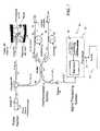
- FIG. 1is a basic all-fiber low-coherence interferometer (LCI);
- FIG. 2depicts an illustrative exponential dependence on z for a scattering material such as human tissue as a sample;
- FIG. 3Adepicts a plot of an illustrative envelope function G( ⁇ l;
- FIG. 3Bdepicts a plot of an illustrative interference signal G( ⁇ l)cos ⁇ s ;
- FIG. 4Adepicts an illustrative exponential decay for a homogeneous scattering sample with space between the probe tip and the sample;
- FIG. 4Bdepicts an illustrative exponential decay for a homogeneous scattering sample with the probe tip immersed in the sample
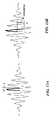
- FIG. 5Adepicts an example of an LCI profile based on observations of the walls of arteries through flowing blood
- FIG. 5Bdepicts a representation of an LCI signal for a calcified plaque on an arterial wall with a lipid pool between the plaque and the arterial wall, looking through blood;
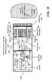
- FIG. 6depicts a system for detecting and characterizing vulnerable plaque in accordance with an exemplary embodiment
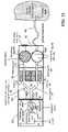
- FIG. 7depicts another system for detecting and characterizing vulnerable plaque in accordance with another exemplary embodiment
- FIG. 8Adepicts a range of unambiguous measurement for a periodic interference signal
- FIG. 8Bdepicts a plot of the interference signal for a single ramp
- FIG. 11depicts an a simplified block depicting a detection scheme employing ramp modulation
- FIG. 12Ashows a balanced interferometric signal resultant from sinusoidal modulation depicting a heavy portion oscillating at the frequency f over the peak;
- FIG. 12Bshows an unbalanced interferometric signal, and a shifted modulation pattern
- FIG. 13depicts an implementation of a sinusoidal modulation or homodyne detection scheme
- FIG. 14depicts a fiber probe and guidewire in accordance with an exemplary embodiment
- FIG. 15Adepicts a probe tip in accordance with an exemplary embodiment
- FIG. 15Bdepicts a probe tip in accordance with another exemplary embodiment
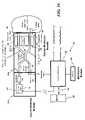
- FIG. 16depicts a minimum configuration interferometer system in accordance with an exemplary embodiment of the invention.
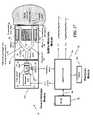
- FIG. 17depicts a configuration of an interferometer system in accordance with an exemplary embodiment of the invention.
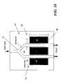
- FIG. 18depicts an illustration of a splitter-modulator module in accordance with an exemplary embodiment
- FIG. 19Adepicts a process for fabricating the splitter-modulator module in accordance with an exemplary embodiment
- FIG. 19Bdepicts a process of fabricating the splitter-modulator module in accordance with an exemplary embodiment
- FIG. 19Cdepicts a process of fabricating the splitter-modulator module in accordance with an exemplary embodiment
- FIG. 20depicts an adaptation of the interferometer system of FIG. 16 / 17 with a calibration strip
- FIG. 21Adepicts an interface for extension modules in accordance with another exemplary embodiment of the invention.
- FIG. 21Bdepicts an interface for extension in accordance with another exemplary embodiment of the invention.
- FIG. 21Cdepicts another interface for extension in accordance with yet another exemplary embodiment of the invention.
- FIG. 22depicts a miniaturized, handheld LCI system in accordance with an exemplary embodiment
- FIG. 23depicts a miniaturized, handheld LCI system in accordance with an exemplary embodiment
- FIG. 24depicts a miniaturized, handheld LCI system in accordance with an exemplary embodiment.
- LCIhigh-sensitivity low coherence interferometric
- instrumentsfor optical metrology, for use in a variety of sensing and monitoring applications, including, but not limited to, trace chemical sensing, optical properties and changes thereof, medical sensing such as detecting and characterizing vulnerable plaques and others.
- the instrumentis miniaturized, using integrated optics components such as waveguides, splitters and modulators on a single substrate such as, but not limited to, a LiNbO 3 (Lithium Niobate) chip.
- LiNbO 3Lithium Niobate
- the exemplary embodimentsmay also involve the use of a “circulator” type of optical component, including of a polarizing beam splitter and quarterwave plate, which can be combined with the light source and detector into a miniature module that prevents optical feedback into the light source while doubling the detected light.
- a “circulator” type of optical componentincluding of a polarizing beam splitter and quarterwave plate, which can be combined with the light source and detector into a miniature module that prevents optical feedback into the light source while doubling the detected light.
- a “circulator” type of optical componentincluding of a polarizing beam splitter and quarterwave plate
- one or more isolators and a waveguide coupler or devices using Faraday rotation in magneto-optic filmsmay be employed in a similar module to accomplish the same purpose.
- Disclosed herein in the exemplary embodimentsare multiple methodologies and associated systems employed to derive information from the magnitude and/or phase of an interferometric signal for detecting and characterizing vulnerable plaques.
- the exemplary embodiments described hereinare suitable for the detection and characterization of vulnerable plaques, the embodiments may further be applicable to detection of other lesions such as skin cancer and lesions lining the walls of internal organs such as the esophagus, colon, etc.
- the methods discussed hereingenerally permit an absolute measurement of the characteristics of atheromatic/atherosclerotic plaque, such as its thickness, as well as relative measurement from a given baseline for a given medium. Therefore, for relative measurements, calibration to establish a baseline may be required. For instance, for one exemplary embodiment, a calibration strip is employed to facilitate calibration. Other methodologies, such as using a sample of known index of refraction may also be employed.
- the light wavelengths discussed below for such methodsmay be in the range of about 300 to about several thousand nanometers (nm), that is, in the spectral range from near ultraviolet to near infrared light. In an exemplary embodiment, for the sake of illustration, a wavelength of about 1300 nm is employed.
- the term “light” as used hereinis not to be construed as being limited or restricted to the visible spectral range. However, it should be appreciated that LCI can occur in any interferometric system using broad frequency or wavelength bandwidth.
- an instrument as described hereincan be configured for measurement at a single depth.
- the instrumentmay be configured to measure both the amplitude and the phase of the interferometric signal as functions of depth.
- Described herein in an exemplary embodimentis a system configured to probe at variable depths and for general imaging purposes, while later embodiments may be employed for measurement at fixed depth.
- probes at various depthsmay be employed to identify the various layers and the respective thickness for each layer of an atherosclerotic plaque, while single depth measurements may be employed to ascertain particular characteristics of the medium of a layer, be it the cap, lipid or otherwise.
- the LCI system of the exemplary embodimentsis preferably configured to be rather small, fiber-optic based, using non-ionizing optical radiation and when implemented with an extensible fiber/guidewire and catheter arrangement facilitates convenient measurements without bulky equipment and apparatus.
- the techniques described in the exemplary embodimentsprovide for characterization of both the tissue structure and biochemistry.
- the exemplary embodimentsadvantageously provide real-time results with excellent spatial resolution ( ⁇ 10 microns or better), which, for a typical broadband light source at 1,300-nm center wavelength and 60 nm bandwidth, is approximately 10 times better than other techniques such as intravenous ultrasound, MRI, and the like.
- the techniques of the exemplary embodimentsdo not require expensive facilities and are relatively inexpensive to manufacture and use. In any case, emphasis is also placed on miniaturization, portability, low power and low cost.
- an LCI systems 10 , 10 bincludes, but is not limited to two optical modules: a source-detector module 20 a and a splitter-modulator module 40 a , and associated processing systems 60 .
- the source-detector module 20 aincluding, but not limited to, a broad-band light source 22 , such as a super luminescent diode (SLD) denoted hereinafter as source or SLD, attached to a single-mode fiber 23 or waveguide, an isolator 24 configured to ensure that feedback to the broad band light source 22 is maintained at less than a selected threshold.
- a broad-band light source 22such as a super luminescent diode (SLD) denoted hereinafter as source or SLD
- SLDsuper luminescent diode
- the source-detector module 20 aalso includes an optical detector 28 .
- the splitter-modulator module 40 aincludes, but is not limited to, a waveguide input 41 , a waveguide output 43 , a splitter/coupler 50 , and two waveguide light paths: one light path, which is denoted as the reference arm 42 , has adjustable length lr with a reflecting device, also referred to as a mirror 46 at its end; the other light path, which is denoted as the sensing arm 44 , allows light to penetrate to a distance z in a medium/object and captures the reflected or scattered light from the medium. It will be appreciated that the captured reflected or scattered light is likely to be only the so-called “ballistic photons”, i.e., those that are along the axis of the waveguide. Provision is also made for one or more modulators 52 , 54 in each of the reference arm 42 and sensing arm 44 respectively.
- the source-detector module 20 bincludes, but is not limited to, a polarized broad-band light source 22 , attached to a single-mode fiber 23 .
- the source-detector module 20 balso includes a polarizing beam splitter 25 with an quarter wave plate 26 employed to ensure a selected polarization configured to facilitate ensuring that feedback to the broad band light source 22 is maintained at less than a selected threshold.
- the source-detector module 20 balso includes an optical detector 28 .
- the splitter-modulator module 40 b of this embodimentincludes, but is not limited to, a waveguide inputs/output 45 , a Y-splitter-combiner 51 , and the two waveguide arms: reference arm 42 , and sensing arm 44 .
- a modulator 52 , 54in each of the reference arm 42 and sensing arm 44 respectively.
- the waveguide arms 42 , 44 and/or fibers 23are configured for single-transverse-mode transmission, and preferably, but not necessarily, polarization-maintaining waveguides or fibers.
- the waveguide and/or fiber tips of each component joinedare configured e.g., angled-cleaved in a manner to minimize reflection at the junctions.
- the LCI system 10 , 10 bmay include, but is not limited to a computer system including central processing unit (CPU) 62 , display 64 , storage 66 and the like.
- the computer systemmay include, but not be limited to, a processor(s), computer(s), controller(s), memory, storage, register(s), timing, interrupt(s), communication interface(s), and input/output signal interfaces, and the like, as well as combinations comprising at least one of the foregoing.
- computer systemmay include signal input/output for controlling and receiving signals from the source-detector module 20 as described herein. Additional features of a computer system and certain processes executed therein may be disclosed at various points herein.
- the processing performed throughout the LCI system 10 , 10 bmay be distributed in a variety of manners as will also be described at a later point herein. For example, distributing the processing performed in one ore more modules and among other processors employed.
- processes and datamay be transmitted via a communications interface, media and the like to other processors for remote processing, additional processing, storage, and database generation. Such distribution may eliminate the need for any such component or process as described or vice versa, combining distributed processes in a various computer systems.
- Each of the elements described hereinmay have additional functionality that will be described in more detail herein as well as include functionality and processing ancillary to the disclosed embodiments.
- signal connectionsmay physically take any form capable of transferring a signal, including, but not limited to, electrical, optical, or radio.
- the light reflected from the reference mirror 46 (Electric field E r ) in the reference arm 42 and the light reflected or scattered from depth z within the medium or sample (Electric field E s ) in the sensing arm 44are combined at the optical detector 28 , whose output current is proportional the combined electric fields.
- the quantity i o ( ⁇ l)is the interference or cross-correlation signal between the two optical fields, and is the signal of interest. It is given by:
- ⁇ o2 ⁇ I r ⁇ I s ⁇ ⁇ G ⁇ ( ⁇ ⁇ ⁇ l ) ⁇ ⁇ cos ⁇ ⁇ ⁇ s ⁇ ⁇
- ⁇ othe center wavelength of the light source 22
- the square root termrepresents the magnitude I s of the LCI signal. It is a function of its starting depth in the sample and the reflection, transmission, and scattering properties of the sample.
- the sampleis a scattering material such as human tissue
- theoryshows I s to have an exponential dependence on z, as illustrated in FIG. 2 for a skin sample.
- This type of profileis predicted by scattering theory in general. The specific profile depends on the type of medium or tissue being examined.
- One of the main features of LCI as applied to scattering tissuesis to experimentally obtain this profile for arbitrary tissues, whether skin for determining features such as glucose concentration, or arterial walls for the detection and characterization of vulnerable plaques.
- the interference signalexhibits maxima and minima of decreasing amplitude over a range determined by ⁇ l.
- the cosine termis the real interference. It undergoes maxima and minima and has a 2 ⁇ or 360 deg phase shift every time ⁇ l changes over a distance equal to the center wavelength of the light.
- a plot of G( ⁇ l)cos ⁇ sis shown in FIG. 3B for an interferometer with the 1,310 nm light source.
- the interference signal i oexhibits significant amplitude only over a spatial window of approximately twice the coherence length L c .
- the coherence length L cdecreases and the spatial measurement window narrows.
- the existence of this gating functionhighlights the ability of LCI to resolve depth or optical path length. It means that, out of all the possible sensing light components that are captured by or back-scattered to the sensing fiber in the interferometer, the only component that contributes to the LCI signal is that for which the reference arm length corresponds to a depth in the sample for which the interferometer is balanced, with a resolution corresponding to the coherence length. All other signals outside of the coherence length remain as parts of the dc current I s .
- the LCI signal obtainedis one that corresponds to a new depth in the sample.
- the measurement of the peak of the gating functiongives the amplitude of the profile of the LCI signal as a function of depth.
- LCIprovides a means for probing objects at precisely defined locations within the object.
- Such an approachsaves time and processing complexity over employing a high-resolution scan alone throughout the entire depth profile of interest.
- phase, ⁇ s , (Equations (2), (5)) of the interference signal i ochanges by 2 ⁇ (from a maximum to a minimum then to another maximum) as ⁇ l varies from 0 to ⁇ o . Therefore, a small change in ⁇ l results in a large phase change.
- the phase of the interference signal i ois highly sensitive to small changes of optical properties of the mediums, such as refractive indices, or depth z. Thus, while moderate to large changes may readily be observed by measuring the magnitude of the envelope G( ⁇ l), small changes are best detected by measuring the phase ⁇ s of the interference signal i o .
- the interference signal i ois repetitive.
- the range from 0 to 2 ⁇ as indicated in FIG. 3is a range for which the desired information can be measured without ambiguity. It may also be noted however, that if the coherence length L c is short enough that the amplitude difference between the main peak and secondary peaks is measurable, or if a means is provided to record a particular point of the interference signal, then phase measurement beyond 2 ⁇ may be realized by counting the fringes (the number of equivalent points traversed) starting from that point.
- the envelope G( ⁇ l), or its peak G( ⁇ l0), which may represent scattering, reflection, and absorption; and the more sensitive changes in cos ⁇ s due to small optical property changes in the specimen under study.
- the more sensitive changes in cos ⁇ s due to small optical property changes in the specimen under studyit is first preferable to separate the DC components I r and I s from G( ⁇ l) and cos ⁇ s in the interferometric signal i o described in Equation (5).
- Every type of sampleexhibits its own distinct trace signature or profile. For example, in the profile of the skin sample depicted in FIG. 3 , the portions that correspond to the stratum corneum, the epidermis, and the dermis may readily be observed.
- a homogeneously scattering samplesuch as milk or a solution containing microspheres in suspension would show a uniform exponential decay as shown in FIG. 16 . In FIG. 16 there is a space between the tip of the interferometer probe and the homogeneously scattering sample. In FIG. 17 , the probe is immersed in the fluid, so the signals from the probe tip and the beginning of the scattering profile coincide.
- FIG. 5depicts an example of LCI profile based on observations of the walls of arteries through flowing blood.
- FIG. 5Adepicts an LCI profile of an arterial wall in a set-up containing blood between the probe tip and the arterial wall simulated by a sheet of rubber.
- FIG. 5Brepresents the LCI signal for a calcified plaque on an arterial wall with a lipid pool between the plaque and the arterial wall, looking through blood.
- the step increase due to the higher scattering coefficient of the plaque and a step decrease resultant from the lower scattering of the lipid poolmay readily be observed. It will be appreciated that by then measuring from the beginning of the hump or step corresponding to the plaque to the beginning of the portion of the signal corresponding to the lipid pool, a measure of the thickness of the plaque cap may be ascertained.
- the accuracy of such a measurementis determined by the accuracy with which the transition can be detected.
- the transitionfrom the calcified plaque cap to lipid pool.
- the transitionmay not be easily detected, with sufficient accuracy, by looking at only the amplitude of the interferometric signal i o .
- it is established that such changesmay be detected from the phase information in the LCI signal.
- any change in material property, whether it is refractive index, absorption, scattering(which can be treated as a change of absorption or reflection) will affect the phase of the interferometric signal i o .
- the changeis abrupt at a given location, it will also translate into an abrupt phase shift in the signal at that location.
- Such abrupt changescan occur at the boundaries between two regions in a sample having different optical properties: refractive index, absorption, scattering, and so on.
- refractive indexrefractive index
- absorptionabsorption
- scatteringand so on.
- the phase of the interferometric signalis expected to vary by a predictable amount for a given medium.
- the thickness of the various layers of a vulnerable plaquemay be ascertained by observing such changes in a layered structure and recording their positions.
- abrupt variations in phase and or index of refractionthe order of about 0.1% per micron of scan distance are considered as likely changes in medium.
- Equation 3the phase angle ⁇ s of the LCI signal, for a depth in the sample determined by l r for an interface at depth nz (which is l s ) is written as:
- ⁇ s2 ⁇ ⁇ ⁇ o ⁇ ( n 1 ⁇ ⁇ ⁇ ⁇ z + z ⁇ ⁇ ⁇ ⁇ ⁇ n ) . ( 6 )
- phase measurementscan easily detect a phase change of such magnitude. This approach makes it possible to observe phase changes discontinuities over a small fraction of wavelength.
- amplitude measurementshave a resolution of the order of the coherence length L c
- phase measurementsprovide a resolution of the order of a fraction of a wavelength ⁇ 0 .
- the combination of amplitude change (when available) and phase changecan thus provide resolution far exceeding that of amplitude measurements alone.
- resolutions of the order of a fraction of a micronare achievable.
- phase measurements of the LCI signalfor detection of vulnerable plaques is that this large phase change occurs regardless of the amplitude of the envelope of the LCI signal, whether the signal is from a location near the surface of the sample or it is from a larger depth where the signal is much weaker due to scattering. This observation is especially significant with the study of vulnerable plaques in human arteries in the presence of blood. Scattering resultant from blood is significant and may reduce the optical signal strength by more than 20 dB before it reaches the arterial walls. Additionally, the light is further scattered by the tissues themselves.
- a phase measurement approachpermits measurement of plaque thickness with high accuracy, even when the signal strength; is highly reduced due to scattering through blood.
- the scattering coefficient ⁇can be considered analogous to the absorption coefficient, since they affect the exponential decay of the LCI signal in similar ways. This adds a term ⁇ m E s e i ⁇ m to the expression for the electric field E at the boundary between the two regions. Since the two media may have different scattering properties, the component of the LCI due to the scattering from the first medium may be identified as S 1 with respect to the incident electric field E i or its related optical power I i . Similarly, the scattering component related to the second media may be identified as S 2 ⁇ , where S 2 may be larger or smaller than S 1 .
- i o ⁇ ( ⁇ ⁇ ⁇ l )2 ⁇ I r ⁇ S 1 ⁇ I i ⁇ ⁇ G ⁇ ( ⁇ ⁇ ⁇ l ) ⁇ ⁇ [ cos ⁇ ( ⁇ s + ⁇ ⁇ ⁇ ⁇ s ) + S 2 ⁇ ⁇ m S 1 ⁇ cos ⁇ ( ⁇ s + ⁇ ⁇ m ) ] ( 8 )
- i o ( ⁇ l )2 D ⁇ square root over (I r S 1 I i ) ⁇
- FIG. 6depicts system for detecting and characterizing vulnerable plaque in accordance with an exemplary embodiment.
- a Michelson interferometersimilar to the interferometer of FIG. 1 , is employed, but also including a fiber-sensing probe 300 designed such that it can fit inside a catheter 304 to facilitate directing probing light toward the arterial walls.
- One way to change the length of the reference armis by using a moving mirror 46 such that the length of the air gap due to the mirror displacement provides the desirable length adjustment for matching a specific depth in the sample.
- the mechanical motion of a movable reflecting device 46e.g., mirror can be replaced by a cable fiber stretcher 91 applied to a length of fiber optic cable 23 .
- the cable stretcher 91may be implemented by wrapping a portion of fiber 23 in the reference arm 42 around a PZT drum 98 and applying a voltage between the inner and outer wall of the drum 98 .
- displacement of 5 to 6 millimetersis sufficient to facilitate the profiling required to characterize plaque in a blood vessel.
- This displacementmay readily be achieved and scanned by applying a voltage ramp of 500–600 volts to a 20–30 millimeters (mm) diameter PZT drum 98 with a few meters length of fiber wound around it.
- a voltage ramp500–600 volts to a 20–30 millimeters (mm) diameter PZT drum 98 with a few meters length of fiber wound around it.
- a longer length of fiber 94 or a higher voltagecan be used, up to the strain limit of the fiber, or one or more individual fiber stretchers 91 can be used in tandem.
- Logically, a longer, but smaller diameter drummay also be used to achieve the desired displacements based on a selected length of fiber 23 .
- FIG. 7depicts a LCI system 10 b utilizing an autocorrelator in accordance with an exemplary embodiment.
- the autocorrelator-based LCI system 10 bincludes three sections.
- an independent probe 300which in this instance includes a fiber 23 , which carries both the reference light and the sensing light.
- a partial mirror 46 bis employed at the tip of the fiber 23 from which part of the light can be reflected and part transmitted is employed.
- the partially reflected lightis denoted and used as the reference light, while the light that is transmitted beyond the partial mirror 46 toward the sample and back-scattered into the fiber 23 is denoted and used as the sensing light.
- the ideal reflection for the reference light from the partial mirror 46is about 33%.
- the sensing lightis very small e.g., there is little back-scattered light
- SNRsignal to noise ratio
- this approachprevents the shot noise at the detector 28 from overpowering the detected interference signal.
- the probe 300is connected to the broadband source 22 by means of a circulator 25 b via an optional isolator 24 .
- a circulator 25 bis a three-port device in which, light injected at one port is transmitted to a second port, but the light reflected from the second port is deflected to a third port (similarly, an isolator together with a splitter (similar to 25 of another embodiment) may also be used, but the circulator 25 b is more efficient).
- the electric field of the reference lightis designated as E r , starting from the value E or , (not shown) at the reflector 46 b .
- the field from the sensing lightis designated as E s , and its initial value is E os from within the sample (not shown).
- E sThe total electric field in the probe, which is the sum of E r and E s is directed to the interferometer section from the third port of the circulator. This light serves as the input to the interferometer.
- polarization-maintaining (PM) fiberin an embodiment using the interferometer, as depicted in FIG. 6 , it may be preferred for an exemplary embodiment to employ polarization-maintaining (PM) fiber.
- PM fibersin the autocorrelator embodiment, as depicted in FIG. 7 , one advantage of having the reference and sensing lights in the same fiber is that ordinary single-mode (SM) fibers may be used instead of polarization maintaining (PM) fibers for the optical system by virtue of the fact that the relative polarization between the reference light and sensing light is always maintained automatically.
- SMsingle-mode
- PMpolarization maintaining
- Maintaining polarizationensures accurate interference between the reference and sensing lights.
- the interferometer section of the LCI system 10 bincludes two arms denoted here 42 b and 44 b for consistency with a means to provide a variable relative delay between them.
- the delaymay be attained by mechanical means, such as a moving reflector denoted 46 b at the end of one arm, for example arm 42 b .
- a preferred meansis to achieve a delay is to avoid moving apparatus associated with moving mirrors and utilize an electrically activated fiber-stretching device such as cable stretcher 91 described above.
- a stretching device 91may be implemented by winding a length of the fiber 23 in each arm 42 b , 44 b around a PZT drum 98 and applying a voltage to the PZT drum 98 .
- a 15-meter length of fiber wound around a 20–30 mm PZT drumprovides a length nL of 5–10 mm, with the application of a peak voltage of about 500 volts in a 50-millisecond ramp.
- the physical lengths of the fiber arms 42 b , 52 bit is acceptable for the physical lengths of the fiber arms 42 b , 52 b to be the same and for the desired delay to be provided only by the PZT stretchers 91 , without the slower mechanical displacement.
- the interferometeris made from single-mode fibers, it is preferable to maintain the same polarization relationship between its two arms.
- Faraday rotator reflectors denoted 46 bare used on each of the two arms 42 b and 44 b at the ends of the in the interferometer.
- a splitter/coupler 50is employed to split the input light E i into two substantially equal components, which are transmitted to, and reflected back from the Faraday mirrors 46 b .
- i s ⁇ ( z )( 1 - R ) ⁇ R ⁇ I r ⁇ I s ⁇ ( z ) ⁇ exp ⁇ [ - ( ⁇ L c ) 2 ] ⁇ cos ⁇ ( 2 ⁇ ⁇ ⁇ o ) ( 10 )
- any of the various means for adjusting an optical path lengthmay be employed to adjust L, including but not limited to cable stretcher, 91 modulators e.g. 52 , 54 , movable reflecting devices, e.g., 46 , and the like, as well as combinations including at least one of the foregoing.
- a separate cable stretcher 91may be employed for the compensation addressed above and a second modulator e.g., 52 , 54 employed for the magnitude and phase detection as described herein.
- a particular advantage of the autocorrelator configuration the LCI system 10 b over the interferometer based LCI system 10is that the optical circuit may be constructed employing simple low cost SM fibers, whereas, the a Michelson interferometer based LCI system of FIG. 6 could require that the optical system to be made out of PM fibers, particularly if the probe is to be part of a catheter. Polarization maintaining fiber is much more expensive than single mode fiber.
- a first methodologyaddresses detection of the amplitude/magnitude of the envelope of the interference signal, while others address detecting the phase, or more specifically a particular phase shift ⁇ s of the interference signal i o with respect to a depth scan.
- the process for the measurement of the phase of the LCI signalis applied to the detection of vulnerable plaques in a blood vessel.
- Detection of plaques with the phase of the interferometric signalincludes a means to measuring phase changes and discontinuous phase change, such as occur at the interface between two media, particularly scattering media for example between blood and a fibrous cap, or between the cap and the lipid pool.
- Equation 6identifies ⁇ s , for the interferometer, the analogous equation for the autocorrelator would similarly be given by
- ⁇ s4 ⁇ ⁇ ⁇ o ⁇ ( n s ⁇ ⁇ ⁇ ⁇ z + z ⁇ ⁇ ⁇ ⁇ ⁇ n s ) .
- the processor 60may be configured to cause the phase and/or magnitude of the interferometric signal to be measured discretely or continuously from one target depth to another target depth. If there is no material discontinuity in the process, the phase shift is generally linear with scanning distance (or time), and its slope (rate of change, first derivative) would be substantially a constant, and the change in the slope (second derivative) would be zero. Any material discontinuity at a given point would be manifested as both in a change of the slope, and in the fact that the second derivative would have a value that is different from zero. Such a value would be positive or negative, depending on whether the index change is positive or negative.
- the process for evaluating these changes in phasecan easily be implemented digitally by storing the phase for each selected target depth during a depth scan and taking the numerical first and second derivatives.
- the magnitudevaries generally with an exponential decay with scanning distance (or time).
- any material discontinuity at a given pointwould be manifested as an abrupt change in the difference and both in a change of magnitude and thereby, the slope, and in the fact in the second derivative.
- the process for evaluating these changes in magnitudecan easily be implemented digitally by storing the magnitude for each selected target depth during a depth scan and taking the numerical first and second derivatives.
- the derivativemay not need to be mathematically robust, but simply an approximation that captures the trend information of the phase of the interferometric signal. For example, considering the phase, given by
- the threshold for measuring the abruptness of the changeis the smallest value of B that can be measured, and is a function of the sensitivity of the instrument, which ultimately depends on the detection noise (e.g., Johnson, shot, and excess intensity noises), and bandwidth in the instrument.
- the detection noisee.g., Johnson, shot, and excess intensity noises
- the abrupt index change thresholdwould be 0.1% per micron of scan distance. It was shown in a previous application that the minimum measurable phase change, as determined by noise is of the order of 10 ⁇ 5 radian or about 6 ⁇ 10 ⁇ 4 degrees.
- the first approachuses a periodic ramp applied to one of the modulators 52 , 54 .
- Another approachalso called a homodyne methodology employs a sine wave applied to one of the modulators 52 , 54 . It will be appreciated that while for the purposes of description of one or more exemplary embodiments, a particular modulator in a particular arm of the LCI system 10 is described as including a modulator, other configurations are conceivable.
- a ramp modulationis applied to one of the interferometer arms, the reference arm 42 , for example, changing l r over a distance from ⁇ b to a over a time period T, such that:
- the resultant of the modulationrepresents a sine wave of frequency f c with an arbitrary phase ⁇ c determined by b, which is amplitude-modulated (AM) by the G( ⁇ l) envelope function, now also a function of time.
- the ramp function used for modulationis periodic, this signal repeats with the periodicity of the ramp function.
- FIGS. 9A and 10Adepict the values of ⁇ l
- FIGS. 9B and 10Bdepict the envelope function as a function of time for the particular G(t) ⁇ l respectively
- FIGS. 9C and 10Cdepict the output current or interference signals for each ⁇ l, respectively.
- the modulator m 1 52may be employed to add an additional offsets denoted as ⁇ to the reference arm 42 corresponding to a group of target depth variations ⁇ z in the vicinity of target depth z.
- FIG. 11depicts a illustrative implementation of the processes 100 that may be employed in accordance with an exemplary embodiment of the invention for determination of the magnitude and/or phase of the interference signal i o .
- the bolded portions of FIG. 11depict an implementation of a detection scheme using the ramp modulator for magnitude determination.
- the optical signalis observed at the optical detector 28 and applied to a narrowband amplifier/filter 110 resulting in the interference signal i o .
- the interference signalis applied to a peak detector 112 to facilitate determination of the magnitude of the envelope of the interference signal i o .
- a ramp generator 114is utilized as the input to modulator m 1 52 ( FIGS. 1 , 6 , 7 , 16 , and 17 ) to facilitate manipulation of the length of one of the arms, in this instance, the reference arm 42 of the LCI system 10 .
- the most sensitive interferometric informationcan be derived from the phase variations of the interference signal i o resulting from small changes in material properties. For example, referring to Equation (5), a small change ⁇ n in the refractive index n, at a depth z in the sample, will result in a corresponding change in ⁇ l by the amount z ⁇ n. To analyze such a change by a ramp modulation method as described above, the ramp described above in Equation (12), is applied to the modulator m 1 52 , but, in addition, an extra optical path length z ⁇ n is also included to facilitate addressing the phase shift in the interference signal i o , yielding:
- the phase shift of interference signal i omay readily be detected using a homodyne process 101 such as depicted in the block diagram of FIG. 11 , which produces output signals proportional to the sine and cosine of the phase shift to be measured.
- the change in ⁇ l produced by the ramp modulationgenerates the interferometric signal i o in the form of a sine wave, cos( ⁇ c t+ ⁇ c + ⁇ n ) as in Equation (16), with an additional phase shifting component, denoted ⁇ n resulting from the change in the refractive index, ⁇ n.
- the parameter a of the ramp modulator 114is applied to a voltage control oscillator (VCO) 120 , configured to generate a sinusoidal function at a frequency ⁇ c proportional to the magnitude a from the ramp modulation.
- VCOvoltage control oscillator
- a closed loop controlleris employed to facilitate determination of ⁇ n as will be described herein.
- the sinusoidal function, cos( ⁇ c t) 122 from the VCO 120is phase shifted with phase angle ⁇ , as depicted at phase shifting process 124 .
- the phase angle ⁇is set to ⁇ /2, to facilitate formation of quadrature sinusoidal signals.
- the phase-shifted sinusoid 126is applied to a first multiplying demodulator 130 configured for the loop closure and denoted as a lock-in amplifier.
- the sinusoidal function cos( ⁇ c t) 122 from the VCO 120 (without the phase shift ⁇ )is also applied to a second multiplying demodulator 132 .
- the interferometric signal i o from the optical detector 28is amplified and filtered through a narrow band filter 110 around ⁇ c , to extract the signal cos( ⁇ c t+ ⁇ c + ⁇ n ), which is then applied to both multipliers 130 and 132 for multiplication by the sinusoidal signal 122 and the phase shifted sinusoidal signal 126 .
- the output of the first multiplier 130contains a term at frequency 2 ⁇ c and a DC term cos( ⁇ c + ⁇ n ⁇ ).
- the second multiplier 132following similar low-pass filtering at process 142 , the dc term is cos( ⁇ c + ⁇ n ).
- both signalsi.e., sine and cosine
- both signalse.g., Equations 17 and 18, are used with their signs being compared to determine the quadrant in which the phase is located to properly obtain the index change.
- both signalsare positive and increase or decrease in opposite manner.
- phase shifts between ⁇ 2 and ⁇they have opposite signs.
- phase shifts between ⁇ and 3 ⁇ /2both are negative, and for phase shifts between 3 ⁇ 2 and 2 ⁇ , they have opposite sign.
- the index of refraction change Ancan be retrieved in several ways.
- ⁇ ⁇ ⁇ n- b z ( 19 )
- zis the selected target probing depth
- bis the magnitude of the change in optical path length introduced to balance the interferometer of the LCI system 10 .
- a voltage proportional to bis transmitted to an optional VCO 150 to generate a sine wave of frequency proportional to b. That frequency may then be converted to a digital signal by means of an optional zero-crossing detector 152 for further utilization or display.
- Equation (19)also indicates that greater sensitivity is obtained by probing deeper into the sample. Conversely, due to scattering and absorption in the probed sample e.g., tissue, the magnitude of the returned signal (Electric field E s ) and thus the interferometric signal i o , is reduced at greater depth in the sample.
- E sElectrode field
- a signalmay be retrieved by means of a high-gain narrow-bandwidth amplifier (at the expense of measurement time).
- itcan be retrieved by means of autocorrelation, again, at the price of measurement time.
- the measurement sensitivityis, substantially independent of the magnitude of the interferometric signal i o .
- the phase shift of the interference signal i ois determined utilizing a sinusoidal modulation technique.
- a small sine wave signal of amplitude ⁇ and frequency fis applied to either of the modulators 52 or another modulator 54 (m 1 for example in FIG. 1 or FIG. 6 in this instance) for the interferometer based LCI system 10 or one of the cable stretching devices 98 of the autorcorrelator configured LCI system 10 b as depicted in FIG. 7 .
- the modulation pattern(the heavy portion of the waveform) shifts resulting in the asymmetry as shown in FIG. 12B by virtue of the optical path change z ⁇ n. Therefore, in an exemplary embodiment, for maintaining a controllable reference phase, provision is made to apply a fixed voltage to modulator m 1 52 with a fixed displacement b and resulting in a phase shift ⁇ c as in the previous case.
- Equation (2)the interferometric signal now includes a DC term J 0 , and an infinite number of harmonics J 1 , J 2 , J 3 , etc. of decreasing magnitude.
- J 0a DC term
- J 1 , J 2 , J 3 , etc.a filter centered at f and one centered at 2f respectively.
- I o02 ⁇ square root over ( I r I s ) ⁇ J o ( ⁇ ⁇ )cos( ⁇ c + ⁇ n ) DC term (25)
- i o1 ( t )4 ⁇ square root over ( I r I s ) ⁇ J 1 ( ⁇ ⁇ )sin( ⁇ c + ⁇ n )cos ⁇ t Fundamental term (26)
- i o2 ( t )4 ⁇ square root over ( I r I s ) ⁇ J 2 ( ⁇ ⁇ )cos( ⁇ c + ⁇ n )cos 2 ⁇ t
- Second harmonic term(27) where G( ⁇ l) ⁇ 1, since ⁇ l ⁇ L c .
- the DC term I o0includes the same information with respect to the argument of interest ⁇ n as the second harmonic term i o2 (t) and may be employed for ascertaining ⁇ n . However, it is not as stable as i o2 (t) and is subject to drift and other environmental factors. Furthermore, the DC term is not readily separable from the other detector DC components I r and I s . On the other hand, i o1 (t) and i o2 (t) are locked to the oscillator frequency, which can be controlled accurately. Therefore, it is preferred that i o1 (t) and i o2 (t) are selected as the interferometer outputs.
- FIG. 13depicts an implementation of a sinusoidal modulation and detection or homodyne methodology shown generally as 200 . Elements similar to earlier embodiments are similarly referenced but incremented by one hundred.
- a source 210generates a sine wave denoted cos ⁇ t of frequency f and second one of frequency 2f locked to the first one (for example, by means of a frequency doubler).
- a frequency f of about 100 KHzis employed, however, it will be evident that other frequencies may readily be utilized depending upon a particular implementation and application of the LCI system 10 or 10 b .
- the frequency selected for modulationis not critical, and may be selected in accordance with a given implementation.
- the frequency selectedis only limited by practical design constraints of a selected implementation e.g., size of components, processing requirements to implement functions, and the like.
- the sine wave at frequency fis fed to modulator m 2 54 and to the upper multiplier 230 (e.g., a lock-in amplifier), and the sine wave at frequency 2f is applied only to the lower multiplier 232 .
- a ramp generator 214similar to that employed in the above embodiments, applies a dc voltage to the m 1 modulator 52 to produce the path length bias b, which is adjustable.
- the path length bias bis adjusted to between 0 and ⁇ o to produce a phase shift ⁇ c between 0 and 2 ⁇ .
- the detected interference signal i ois amplified and passed through narrow-band filters 210 to produce signals at ⁇ and at 2 ⁇ , and these two signals are fed to the multipliers 230 and 232 respectively as shown.
- Equations (28) and (29)are identical to those in Equations (17) and (18) which were obtained from the ramp modulation scheme described earlier.
- sinusoidal modulationis more robust and does not need special precautions to generate and control the reference frequency f and the ⁇ /2 electronic phase shift as in the previous case.
- the selection of the operating frequency fis arbitrary. However, it is preferable to keep it above the shot noise frequency range, i.e., above 120 KHz, where the shot noise is not significant.
- Equations (28) and (29)may then be utilized in a fashion similar to that employed with Equations (17) and (18) in order to measure the phase shift due to the change in index of refraction ⁇ n without ambiguity between 0 to 2 ⁇ .
- the value of ⁇ nmay also be obtained from the values in Equations (28) and (29), the known values of J 1 , J 2 , and the magnitude of the I s and I r (which may be obtained via a calibration), and setting/driving ⁇ c to zero.
- a digital output indicative of the value of bmay be obtained to facilitate the computation of ⁇ n.
- the implementation depicted in FIG. 13includes optional provisions to measure the peak of the interferometric signal i o under the application of a ramp to provide information on reflection and scattering coefficients. It also contains provision to apply a signal to an optional additional modulator (such as a fiber coil around a PZT drum) to facilitate ranging measurements by means of extra delays applied to the reference arm 42 .
- an optional additional modulatorsuch as a fiber coil around a PZT drum
- phase of the interferometric signalAnother significant aspect of an exemplary embodiment of the invention employing the phase of the interferometric signal is the benefit achieved in measurement of the magnitude as described above.
- the magnitude of the interferometric signalis also measured. It should be appreciated that at the instant the added phase ⁇ c is set/driven to zero, the magnitude is at the absolute peak. Therefore, the phase measurement facilitates determination of the magnitude with the highest possible accuracy. Again, this approach is superior to existing magnitude detection methods because they do not employ the high resolution phase to control the measurement of the magnitude.
- FIG. 14represents a possible embodiment of a probe 300 for the detection and measurement of vulnerable plaques and the way it “looks” at the wall of a blood vessel.
- the probe 300includes one or more fibers 23 placed around a guide wire or inside a guide wire 302 within a FDA-approved catheter 304 .
- the illustrationshows a blood vessel including a vulnerable plaque at a location corresponding to one of the probe elements (e.g., number 3 as indicated in the figure).
- FIG. 15Adepicts a configuration for a system that uses an interferometer as the sensing instrument e.g., LCI system 10 .
- the tips of the fibers 23are angled at about 45 degrees and the 45-degree surface is reflection-coated to maximize the light output toward the wall of the blood vessel.
- the tip of the probe 300is preferably capped with an inert material such as epoxy and shaped such as to protect the fiber tips and prevent damage to the blood vessel.
- FIG. 15Bdepicts a similar embodiment for use in an autocorrelator configured LCI system 10 b , where each fiber 23 element also includes a partial reflector 46 b as discussed earlier and the optional extra delays 47 represented by lengths L 1 and L 2 .
- Sensitivityis limited by noise, once the measurement interferometric signal i o is at or about the noise level it becomes impossible to discern the measurement from noise. Therefore, appreciation of the impact and contributions of noise components becomes instructive with respect to practical considerations of measurement limitations.
- the detection of the information in Equation (28)is limited by fluctuation noise.
- the minimum detectable signalis reached when it is equal to the noise, i.e., when the signal-to-noise ratio (SNR) is equal to unity.
- the noise poweris expressed in terms of the photocurrent variance ⁇ i 2 , which consists of the detector noise ⁇ r 2 , the photon shot noise ⁇ s 2 and for the case of a broadband source 22 , the excess photon noise ⁇ e 2 .
- the SNR(for signal I o1 for a 1-ohm input resistance, for example), is given by:
- the minimum detectable index changedepends inversely on the probing depth. At a depth of 1 mm, i.e., 1000 mm, the minimum index change is ⁇ n (min) ⁇ 4 ⁇ 10 ⁇ 9 . At 2 mm probing depth then ⁇ n (min) ⁇ 2 ⁇ 10 ⁇ 9 . It also depends on the square root of the detection bandwidth, so a factor of three reduction is obtained by reducing the bandwidth from 1 KHz to 100 Hz. The improvement in sensitivity of the phase measurement approach over the amplitude measurement approach stems from the phase factor sin( ⁇ n ) in the expression for the phase signal, which does not exist in the amplitude case.
- the amplitude signalFor example, for optical power below approximately 0.1 mW or equivalently for detector current below approximately 0.1 mA, the dominant noise source is the thermal noise.
- the sensitivityis obtained in the same manner as above, but with the excess noise replaced by the thermal noise in the expression for the SNR. This changes_z ⁇ n(min) somewhat, but does not change the fact that it is a small value.
- ⁇ n (max)⁇ 1.3 ⁇ 10 ⁇ 3 at 1-mm probing depth
- ⁇ n (max)⁇ 6.5 ⁇ 10 ⁇ 4 at 2-mm probing depth.
- the range of the instrumentis the ratio of the maximum to minimum detectable signals. For the examples discussed herein, this range is 3 ⁇ 10 5 or 55 dB.
- methodology that may be employedis to use the envelope detection method or a combination of phase and envelope detections as described earlier.
- broadband light sources 22including, but not limited to, SLD's are laser type structures configured and designed to operate substantially without feedback, e.g., of the order of less than 10 ⁇ 3 , preferably less than 10 ⁇ 4 , more preferably less than 10 ⁇ 5 .
- the spectrum of the SLD light source 22may be distorted, the coherence is significantly increased and the spectrum can exhibit very large ripples and even lasing spikes, and thereby may become lasers. Therefore, to prevent distortion and maintain spectral integrity, low coherence, and broadband characteristics, reflections back into the light source 22 are avoided to maintain a broadband light source 22 .
- isolationis provided to alleviate feedback to the light source 22 .
- the source-detector module 20 a , 20 bis configured to prevent the reflected interferometer light from reaching the SLD light source 22 and upsetting its operation.
- the SLD source 22is designed and configured such that it is linearly polarized.
- SLDs and lasersare “heterostructures”, semiconductor devices consisting of a thin “active” layer sandwiched between two “cladding” layers of lower refractive index, all epitaxially grown on a single crystal substrate.
- MOCVDmetalorganic chemical vapor deposition
- One of the cladding layersis p-doped, and the other is n-doped.
- the substrateis typically n-doped, and the n-cladding layer is the first to be deposited on it.
- the structureforms a p-n semiconductor junction diode, in which the active layer is caused to emit light of energy equal to its bandgap upon the application of an electric current.
- the structureis called heterostructure because the active and clad layers are made of different material. This is in contrast with ordinary diodes in which the p-n junction is formulated between similar materials of opposite doping.
- the use of heterostructurehas made it possible to confine the electrical carriers to within the active region, thus providing high efficiency and enabling operation at room temperature.
- lightis emitted in both TE polarization (the electric field in the plane of the layer) and TM polarization (electric field perpendicular to the layer).
- the active layeris sufficiently thin such that quantum mechanical effects become manifest.
- Such thin layersare called “quantum well” (QW) layers.
- QWquantum well
- the active layercan be “strained”, i.e., a slight mismatch (of about 1%) with respect to the substrate crystal lattice can be introduced during the deposition of the QW layer.
- the straincan modify the transition characteristics responsible for light emission in beneficial ways.
- the lightis completely polarized in the TE mode if the strain is compressive.
- such a linearly polarized light source 22is employed.
- the light from the light source 22is directed through an isolator 24 configured to transmit light in one direction, while blocking light in the opposite direction.
- the lightis directed to a splitter/coupler 50 of the splitter-modulator module 40 a .
- the source-detector module 20 aalso contains a detector 28 to receive from the splitter/coupler 50 .
- the linearly polarized light from the SLD light source 22is collimated with lenses 27 and applied to a splitter 25 .
- a basic 50/50 splitter 24is employed, half of the returned light goes to the detector 28 and the other half is directed to the SLD light source 22 .
- an isolator 24may be employed to prevent feedback to the light source 22 .
- the splitter 25is a polarizing beam splitter 25 operating in cooperation with a quarter wave plate 26 , employed to prevent feedback light from reaching the light source 22 .
- the polarizing beam splitter 25facilitates the elimination of feedback to the SLD light source 22 by redirecting substantially all the reflected light from the splitter-modulator module 40 b to the detector 28 .
- the splitter 25transmits the horizontally polarized light to the quarter wave plate 26 , which coverts the light to another polarization, (for example, circular polarization). Likewise, the returning, circularly polarized light is received by the quarter wave plate 26 and is reconverted to a linear polarization. However, the linear polarization opposite, for example, vertical.
- the vertically polarized lightis transmitted to the polarizing beam splitter 25 , which directs all of the light to the detector 28 .
- this approachtransmits substantially all of the light i.e., the interference signal, to the detector 28 .
- embodiments employing the isolator 24transmits approximately half of the light to the detector 28 .
- the polarizing beam splitter 25is a device that transmits light of one polarization (say the horizontal, or TE-polarized SLD light) and reflects at 90° any light of the other polarization (e.g., vertical or TM-polarized).
- the quarter-wave plate 26is a device that converts a linearly polarized incident light to circular polarization and converts the reflected circularly polarized light to a linearly polarized of the other polarization, which is then reflected at a 90° angle by the polarizing beam splitter 25 to the detector 28 .
- an SLD chip for the light source 22has dimensions of approximately 1 mm ⁇ 0.5 mm ⁇ 0.1 mm (length ⁇ width ⁇ thickness), and emits a broadband light typically of up to 50 mW upon the application of an electric current of the order of 200–300 mA.
- the lightis TE-polarized if the active layer is a compressively strained QW.
- the FWHM spectrumis of the order of 2% to 3% of the central wavelength emission.
- a SLD light source 22 with 1.3 ⁇ m center wavelength emission and operating at 10 mW output power at room temperaturewould have a bandwidth of about 40 nm and would require about 200 mA of current.
- the SLD light source 22may be mounted on an optional thermoelectric cooler (TEC) 32 a few millimeters larger than the SLD light source 22 chip to maintain the temperature of the light source 22 within its specified limits.
- TECthermoelectric cooler
- the SLD light source 22 and associated TEC 32 peripherals in continuous operationwould have the largest power consumption in the LCI system 10 .
- the SLD junction temperaturewould rise by several degrees under the applied current and would operate at reduced efficiency.
- the utilization of a TEC 70may readily be avoided without incurring the effects of significant temperature rise by pulsed operation of the SLD light source 22 .
- Pulsed operationhas the further advantage of reducing the SLD electrical power requirement by a factor equal to the pulsing duty cycle.
- only a single pulseis sufficient to generate an interference signal and retrieve the desired information. Therefore, for example, with pulses of duration 10 ⁇ s and 1% duty factor, the LCI system 10 of an exemplary embodiment can average 1000 measurements per second without causing the temperature of the SLD light source 22 to rise significantly.
- the LCI system 10should preferably be designed for the SLD light source 22 to operate in a pulsed mode with a low duty cycle and without a TEC 32 .
- the source-detector module 20would be on the order of about 2 centimeters (cm) ⁇ 2 cm ⁇ 1 cm.
- the splitter-modulator module 40 a , and 40 b of an exemplary embodimentincludes a splitter/coupler 50 and Y-splitter/combiner 51 respectively, with a “reference” arm 42 and a “sensing” arm 44 , the reference arm 42 having a slightly longer optical path (for example, 1 to 3 mm for measurements in biological tissues) than the sensing arm 44 .
- the optical path difference between the two arms 42 , 44is configured such that the LCI system 10 balanced for the chosen probing depth z. Provision is also made to include a modulator m 1 52 and m 2 54 in the reference arm 42 and sensing arm 44 respectively.
- the splitter/coupler 50 , Y-splitter/combiner 51 reference arm 42 and a sensing arm 44are formed as waveguides in a substrate 53 .
- FIG. 18depicts an illustration of a splitter-modulator module 40 b with a Y-splitter 51 and two modulators 52 , 54 integrated on a LiNbO3 substrate 53 .
- the substrate 53 for this moduleshould preferably, but not necessarily, be selected such that the waveguides of the arms 42 , 44 and modulators 52 , 54 can be fabricated on/in it by standard lithographic and evaporation techniques.
- the waveguides of the arms 42 , 44are fabricated by thermal diffusion of titanium or other suitable metal that increases the index of refraction of the substrate 53 , evaporated through masks of appropriate width for single transverse-mode operation.
- the waveguidesare formed by annealed proton exchange in an acid bath. This process raises the refractive index in the diffusion region, thus creating a waveguide by virtue of the refractive index contrast between the diffusion region and the surrounding regions.
- is lithium niobate (LiNbO3)is employed as a substrate 53 . It will be appreciated that other possible materials, namely ferroelectric crystals, may be utilized such as lithium tantalite (LiTaO3) and possibly indium phosphide depending on configuration and implementation of the LCI system 10 .
- Lithium niobateis a ferroelectric crystal material with excellent optical transmission characteristics over a broad wavelength range from the visible to the infrared. It also has a high electro-optic coefficient, i.e., it exhibits a change of refractive index under the application of an external electric field. The refractive index change is proportional to the electric field. The speed of light in a transparent solid is slower than in vacuum because of its refractive index. When light propagates in a waveguide built into the electro-optic material, an applied electric field can alter the delay in the material, and if the electric field is time-varying, this will result in a phase modulation of the light.
- the LiNbO3 materialis very stable, the technology for making it is mature, and LiNbO3 modulators, which can be compact and are commercially available.
- the high electro-optic coefficient (refractive index change with applied electric field) of lithium niobateis exploited to facilitate implementation of a modulator, such as modulators m 1 52 and m 2 54 .
- a modulatoris implemented on or about the waveguide arms 42 , 44 , by depositing metal electrodes 56 , 58 in close proximity to the waveguide arms.
- the metal electrodes 56 , 58are deposited on the sides of the waveguide arms 42 , 44 .
- the metal electrodes 56 , 58may be deposited on the waveguide arms 42 , 44 with an appropriate insulation layer, in a selected region.
- 16 and 17also shows a diagrammatic depiction of a modulators m 1 52 , m 2 54 in each arm 42 , 44 fabricated by depositing metal films (electrodes) 56 on the outside the waveguides and a larger “common” electrode 58 between them.
- Modulation with modulator m 1 52is obtained by applying a voltage between the upper electrode 56 and the common electrode 58
- modulation with modulator m 2 54is obtained by applying a voltage between the lower 56 and the common electrodes 58 .
- the change of refractive index with applied voltageresults in a delay or a change of optical path between for the modulated arm 52 , 54 . For a given applied voltage, the optical path change depends on the length of the electrodes 56 , 58 .
- FIGS. 19A–CThe process of fabricating a modulator in an exemplary embodiment is illustrated in FIGS. 19A–C .
- Titanium and a lithium niobate substrate 53are employed.
- a waveguide patternis etched in a mask and a thin layer of titanium is vacuum-deposited onto the substrate 23 through the mask.
- the substrate 23is then heated in an oven at about 900–1000 degrees C. to diffuse the titanium into the lithium niobate substrate 23 .
- the index of refraction of the diffusion regionis slightly higher than that of the surrounding material, and this constitutes waveguides in which light is guided in the diffusion region by virtue of its higher refractive index (just as in an optical fiber where the light propagates in the higher index core).
- the metal electrodes 56 and 58 for the modulator(s) 52 , 54are deposited on the sides as shown, with a small spacing d between them.
- Application of a voltage V between one of the outer electrodes 56 and the negative center electrode 58establishes an electric field of value V/d across the waveguide e.g. reference arm 42 and/or sensing arm 44 .
- the width of the waveguideis approximately 3–5 microns, and the spacing d is only a few more microns wider.
- n othe refractive index
- rthe electro-optic coefficient
- the reference arm 42is terminated in an evaporated mirror (metal or quarter-wave stack) 46
- the sensing arm 44is terminated in an anti-reflection (AR) coating, or is covered with an index-matching agent 48 that prevents or minimizes reflection from the end of the sensing arm 44 when placed in contact with the object to be measured.
- splitter-modulator module 40 of an exemplary embodimentwould be on the order of about 2 cm ⁇ 2 cm ⁇ 0.5 cm. Smaller and larger sized modules are envisioned based on the various implementations of the exemplary embodiments employed.
- FIG. 20depicts an exemplary embodiment of the LCI system 10 , 10 b of FIGS. 16 and 17 with a calibration strip 70 in place.
- the calibration strip 70can serve the dual purpose of calibration and refractive index matching.
- the phase associated with a selected length of the reference arm 42is pre-calibrated to correspond to a set depth (or zero in one instance).
- the spot size for the light at the tip of the sensing fiber or waveguide of the sensing arm 44is on the order of a few microns.
- the LCI system 10may readily be calibrated by placing a strip of known parameters, e.g., refractive index (and the like) and appropriate thickness at the sensing end of the splitter-modulator module 40 prior to performing a measurement.
- the calibration strip 70 and associated processingmay be configured such that the LCI system 10 provides a first reading when the calibration strip 70 is not in contact with the LCI system 10 and a corrected reading when in contact with the calibration strip.
- the calibration stripmay be configured as a disposable item.
- FIGS. 21A–21Cdepict various adapters and several expansion or extension modules 90 , 92 , which can be attached to the modular LCI system 10 , 10 b of FIGS. 16 and 17 , for example, to provide additional versatility and functionality.
- FIG. 21A–21Cdepict various adapters and several expansion or extension modules 90 , 92 , which can be attached to the modular LCI system 10 , 10 b of FIGS. 16 and 17 , for example, to provide additional versatility and functionality.
- 21Adepicts an adapter 80 , configured, in one exemplary embodiment as a short section of waveguides 82 , preferably, but not necessarily, made of the same material as the splitter-modulator 40 a , 40 b , with mirror 46 and AR coating 48 , which can be attached to the splitter-modulator 40 a , 40 b (with matching fluid) to operate as an interface for various extension modules 90 , 92 .
- the purpose of the extension module 90is to provide for adequate lengths of the reference and sensing arms 42 , 44 while using a minimum of space, and for adjusting the length of the reference arm 42 and/or sensing arm 44 to enable probing at various depths for example the extension modules may even be employed to facilitate the interferometer portion of the autocorrelator embodiment for the LCI system 10 b of FIG. 17 .
- the length of the arms 42 , 44can be adjusted in any number of ways, including mechanically changing an air gap between two sections of the reference arm, moving the mirror 46 , actually modifying the length of the arm, and the like, as well as combinations including at least one of the foregoing.
- a preferred way to manipulate the length of an arm 42 , 44 , in this instance the reference arm 42is to perform this operation electromechanically.
- an extension modules 90 and 92including windings of two lengths of single-mode fibers 94 , 96 , preferably a polarization maintaining fiber (PMF), (reference and sensing arms respectively) on two drums 98 a and 98 b .
- the drum for the reference arm 42is made out of a piezoelectric material such as, but not limited to PZT (lead zirconate titanate).
- the diameter of the drums 98 a , 98 bis selected to be large enough to prevent radiation from the fibers 94 , 96 due to the bending for example, about 3–4 centimeters (cm).
- the diameter of the fibers 94 , 96 with claddingsis of the order of 0.12 mm.
- the application of a voltage to the PZT drum 98 acauses it to expand or contract, thus straining the reference fiber 94 (for example) and changing its effective length and thereby the optical path length for the reference arm 42 . Therefore, as the total length of the unstrained fiber is increased, the total expansion increases as well. For example, if the strain limit for the fiber 94 is about ⁇ l/l is 10 ⁇ 4 , then, it requires a 10-meter length of fiber 94 to provide for about a 1 mm extension.
- a length tens of metersis relatively easy to achieve if the fiber 94 is not too lossy.
- the absorption in optical fibers 94 , 96is of the order of 0.2 dB/Km. There for the losses associated with a 10 meter length would be quite small.
- the approach of using a voltage applied a piezoelectric drum e.g., 98 a wound with a fiber 94 coilis an effective means to provide changes of several millimeters in the optical path length of the reference arm 42 .
- extension module 90is configured to provide the extension of the reference and sensing arms 42 and 44 as described above and interfaces with an adapter 80 to facilitate depth profiling.
- Extension module 92also includes an evaporated metal mirror 46 to terminate the reference arm 42 , while the sensing arm 44 is terminated with a fiber probe 300 configured to facilitate probing such as may include a guidewire 302 and catheter.
- FIGS. 22 and 23depict various implementations of the extended instrument starting from the base configuration depicted in FIGS. 16 and 17 and using the adapter and the extension modules 80 , 90 , and 92 .
- FIG. 22depicts a configuration of an exemplary embodiment where in addition to the source-detector module 20 a , 20 b and splitter modulator module 40 a , 40 b and extension module 90 and adapter 80 are employed. This configuration facilitates probing at various depths as well as facilitating depth profile scanning.
- FIG. 22depicts a configuration of another exemplary embodiment where in addition to the source-detector module 20 and splitter modulator module 40 and extension module 92 including an external probe 300 are employed. This configuration facilitates probing either at a distance from the device or remote internal probing such as with a catheter and guidewire 302 .
- the LCI system 10is packaged in a small enclosure 12 and includes, but is not limited to, various modules including, but not limited to source-detector module 20 a , 20 b , splitter-modulator module 40 a , 40 b and may include one or more additional extension, adapter or interface modules such as 80 , 90 , and 92 or even calibration strip 70 .
- processing system 60including processor 62 (not shown in this view) associated controls 63 e.g., keys, selectors, pointers, and the like, display 64 , data media 66 , as well as communication interfaces 65 , and the like as well as rechargeable batteries.
- processor 62not shown in this view
- controls 63e.g., keys, selectors, pointers, and the like
- display 64e.g., data media 66
- communication interfaces 65e.g., rechargeable batteries.
- rechargeable batteriese.g., rechargeable batteries.
- the LCI system 10 as packaged in enclosure 12should be comparable in size to that of a Personal Digital Assistant (PDA) or small handheld instrument, e.g., about 8 cm ⁇ 12 cm ⁇ 3 cm to readily facilitate handheld operation. It should be appreciated, that the package could be larger or smaller as needed to fit the desired component configurations.
- PDAPersonal Digital Assistant
- small handheld instrumente.g., about 8 cm ⁇ 12 cm ⁇ 3 cm to readily facilitate handheld operation
- LCI system 10may be enclosed within the enclosure 12 , or associated with an external processing unit 14 , or remotely located, such as with a computer processing system 60 in another facility 16 .
- the LCI system 10may also include communication interfaces 65 , including wireless interfaces (e.g., infrared, radio frequency, or microwave transmitter/receiver) similar to modem computers, cell phones, PDAs, and the like to enable communication, including, but not limited to Internet communication, with external systems 14 and remote facilities 16 .
- wireless interfacese.g., infrared, radio frequency, or microwave transmitter/receiver
- a sensing portion including the source-detector module 20 a , 20 b and splitter-modulator module 40 a , 40 bcan be detachable, in the form small handheld device, while the rest of the remainder of the LCI system 10 may be in a separate package, separate computer, and the like.
- the disclosed inventioncan be embodied in the form of computer, controller, or processor implemented processes and apparatuses for practicing those processes.
- the present inventioncan also be embodied in the form of computer program code containing instructions embodied in tangible media 66 such as floppy diskettes, CD-ROMs, hard drives, memory chips, or any other computer-readable storage medium, wherein, when the computer program code is loaded into and executed by a computer, controller, or processor 62 , the computer, controller, or processor 62 becomes an apparatus for practicing the invention.
- the present inventionmay also be embodied in the form of computer program code as a data signal 68 for example, whether stored in a storage medium, loaded into and/or executed by a computer, controller, or processor 62 or transmitted over some transmission medium, such as over electrical wiring or cabling, through fiber optics, or via electromagnetic radiation, wherein, when the computer program code is loaded into and executed by a computer 62 , the computer 62 becomes an apparatus for practicing the invention.
- the computer program code segmentsconfigure the processor to create specific logic circuits.
Landscapes
- Health & Medical Sciences (AREA)
- Life Sciences & Earth Sciences (AREA)
- Physics & Mathematics (AREA)
- Pathology (AREA)
- General Health & Medical Sciences (AREA)
- Engineering & Computer Science (AREA)
- Veterinary Medicine (AREA)
- Biophysics (AREA)
- Biomedical Technology (AREA)
- Heart & Thoracic Surgery (AREA)
- Medical Informatics (AREA)
- Molecular Biology (AREA)
- Surgery (AREA)
- Animal Behavior & Ethology (AREA)
- Public Health (AREA)
- General Physics & Mathematics (AREA)
- Biochemistry (AREA)
- Analytical Chemistry (AREA)
- Chemical & Material Sciences (AREA)
- Immunology (AREA)
- Optics & Photonics (AREA)
- Cardiology (AREA)
- Emergency Medicine (AREA)
- Radiology & Medical Imaging (AREA)
- Nuclear Medicine, Radiotherapy & Molecular Imaging (AREA)
- Physiology (AREA)
- Spectroscopy & Molecular Physics (AREA)
- Vascular Medicine (AREA)
- Investigating Or Analysing Materials By Optical Means (AREA)
Abstract
Description
Id=η|Er+Es|2=Ir+Is+io(Δl) (1)
where η is the detector quantum efficiency (typically <1), Ir=ηEr,Er* is the detector current due to Eralone, Is=ηEs,Es* is the detector current due to Esalone, and the * represents the complex conjugate. Er,Er* and Es,Es* represent the optical power in the reflected reference field and reflected sensing field, respectively. The quantity io(Δl) is the interference or cross-correlation signal between the two optical fields, and is the signal of interest. It is given by:
and where λois the center wavelength of the
Δl=lr−lswherels=nz (3)
where lris the path length change in the
where Δλ is the FWHM (full width half maximum) linewidth of the
In the transition from
Application of some algebraic manipulation facilitates reduction this signal to the simpler form
io(Δl)=2D√{square root over (IrS1Ii)}|G(Δl)|cos(φs+ζ) (9)
where D is a new constant and ζ is the total phase shift. However, it should be appreciated that this derivation is not necessary to illustrate the results. It suffices to note that for the same small values of Δn discussed above and for small values of Δk (i.e., k2−k1), Δφsremains large at ˜196 degrees whereas both the amplitude step S2Γm/S1and the extra phase component φm, or ζ are negligibly small. However, for k1=10 k2(transition from a medium with large scattering to one with low scattering, then S2Γm/S1˜1.9 (a measurable increase) and the additional phase shift φmis ˜36 degrees, also measurable. Nevertheless, advantageously, Δφ2remains the largest measurable change.
where R is the power reflection coefficient at the probe tip, and where
Δ=4nL−2(nsz) (11)
where nsis the refractive index of the sample, while for the autocorrelator, an analogous equation given as
where n is the refractive index for the fiber. Likewise, as
so that in scanning from location z1to location z2within a medium of constant or slowly varying refractive index n, the phase changes from
such that its first derivative is the constant A given as:
This yields:
and writing G(Δl)˜1 for a˜λo, yields:
from the first modulator:ILP=√{square root over (IrIs)} sin(φc+φn) and (17)
from the lower modulator:ILP=√{square root over (IrIs)} cos(φc+φn) (18)
where z is the selected target probing depth and b is the magnitude of the change in optical path length introduced to balance the interferometer of the
Δl=zΔn+b+δ cos ωt (20)
and the general form of φsis:
where ω=2πf and φδ=2πδ/λo.
Taking the cosine of the equation and converting yields:
cos φs=cos(φn+φc)cos(φδ cos ωt)−sin(φn+φc)sin(φδ cos ωt). (22)
The resultant is a phase-modulated signal, which can be expanded into the Fourier-Bessel series, using:
where Jn(x) is the Bessel function of the first kind of argument x and integer order n.
Io0=2√{square root over (IrIs)}Jo(φδ)cos(φc+φn) DC term (25)
io1(t)=4√{square root over (IrIs)}J1(φδ)sin(φc+φn)cos ωtFundamental term (26)
io2(t)=4√{square root over (IrIs)}J2(φδ)cos(φc+φn)cos 2ωtSecond harmonic term (27)
where G(Δl)≈1, since Δl<<Lc.
Io1=2√{square root over (IrIs)}J1(φδ)sin(φc+φn) (28)
I02=2√{square root over (IrIs)}J2(φδ)cos(φc+φn). (29)
σi2=σr2+σs2+σe2 (30)
indicating for a broad band source only the excess intensity noise need be considered to evaluate sensitivity. In addition, analysis of the excess intensity noise permits determination of the advantages of employing a phase based techniques of detection/measurement of the interferometric signal io.
(zΔn)min≈4×10⁻⁶μm (33)
(zΔn)max=λo (34)
where nois the refractive index, and r is the electro-optic coefficient. The phase shift of a light of wavelength λ propagating in a LiNbO3 modulator is given by
where L is the length of the
Typical material properties are:
r=11.3×10⁻¹²m/V
no=2.35
Claims (70)
Priority Applications (2)
| Application Number | Priority Date | Filing Date | Title |
|---|---|---|---|
| US11/041,177US7190464B2 (en) | 2004-05-14 | 2005-01-21 | Low coherence interferometry for detecting and characterizing plaques |
| PCT/US2006/002244WO2006079011A1 (en) | 2005-01-21 | 2006-01-20 | Low coherence interferometry for detecting and characterizing plaques |
Applications Claiming Priority (2)
| Application Number | Priority Date | Filing Date | Title |
|---|---|---|---|
| US10/845,849US7184148B2 (en) | 2004-05-14 | 2004-05-14 | Low coherence interferometry utilizing phase |
| US11/041,177US7190464B2 (en) | 2004-05-14 | 2005-01-21 | Low coherence interferometry for detecting and characterizing plaques |
Related Parent Applications (1)
| Application Number | Title | Priority Date | Filing Date |
|---|---|---|---|
| US10/845,849Continuation-In-PartUS7184148B2 (en) | 2004-05-14 | 2004-05-14 | Low coherence interferometry utilizing phase |
Publications (2)
| Publication Number | Publication Date |
|---|---|
| US20050254061A1 US20050254061A1 (en) | 2005-11-17 |
| US7190464B2true US7190464B2 (en) | 2007-03-13 |
Family
ID=36282910
Family Applications (1)
| Application Number | Title | Priority Date | Filing Date |
|---|---|---|---|
| US11/041,177Expired - Fee RelatedUS7190464B2 (en) | 2004-05-14 | 2005-01-21 | Low coherence interferometry for detecting and characterizing plaques |
Country Status (2)
| Country | Link |
|---|---|
| US (1) | US7190464B2 (en) |
| WO (1) | WO2006079011A1 (en) |
Cited By (156)
| Publication number | Priority date | Publication date | Assignee | Title |
|---|---|---|---|---|
| US20060039004A1 (en)* | 2004-08-06 | 2006-02-23 | The General Hospital Corporation | Process, system and software arrangement for determining at least one location in a sample using an optical coherence tomography |
| US20060109478A1 (en)* | 2004-11-24 | 2006-05-25 | The General Hospital Corporation | Devices and arrangements for performing coherence range imaging using a common path interferometer |
| US20060227333A1 (en)* | 2003-03-31 | 2006-10-12 | Tearney Guillermo J | Speckle reduction in optical coherence tomography by path length encoded angular compounding |
| US20060279742A1 (en)* | 2005-06-01 | 2006-12-14 | The General Hospital Corporation | Apparatus, method and system for performing phase-resolved optical frequency domain imaging |
| US20070009935A1 (en)* | 2005-05-13 | 2007-01-11 | The General Hospital Corporation | Arrangements, systems and methods capable of providing spectral-domain optical coherence reflectometry for a sensitive detection of chemical and biological sample |
| US20070035743A1 (en)* | 2005-08-09 | 2007-02-15 | The General Hospital Corporation | Apparatus, methods and storage medium for performing polarization-based quadrature demodulation in optical coherence tomography |
| US20070055117A1 (en)* | 2004-05-14 | 2007-03-08 | Alphonse Gerard A | Low coherence interferometry utilizing phase |
| US20070076212A1 (en)* | 2005-09-30 | 2007-04-05 | Zuluaga Andres F | Detecting vulnerable plaque |
| US20070081236A1 (en)* | 2005-09-29 | 2007-04-12 | The General Hospital Corporation | Method and apparatus for optical imaging via spectral encoding |
| US20070171433A1 (en)* | 2006-01-20 | 2007-07-26 | The General Hospital Corporation | Systems and processes for providing endogenous molecular imaging with mid-infrared light |
| US20070177152A1 (en)* | 2006-02-01 | 2007-08-02 | The General Hospital Corporation | Methods and systems for monitoring and obtaining information of at least one portion of a sample using conformal laser therapy procedures, and providing electromagnetic radiation thereto |
| US20070188855A1 (en)* | 2006-01-19 | 2007-08-16 | The General Hospital Corporation | Apparatus for obtaining information for a structure using spectrally-encoded endoscopy teachniques and methods for producing one or more optical arrangements |
| US20070201033A1 (en)* | 2006-02-24 | 2007-08-30 | The General Hospital Corporation | Methods and systems for performing angle-resolved fourier-domain optical coherence tomography |
| US20070233056A1 (en)* | 2006-02-08 | 2007-10-04 | The General Hospital Corporation | Methods, arrangements and systems for obtaining information associated with an anatomical sample using optical microscopy |
| US20070238955A1 (en)* | 2006-01-18 | 2007-10-11 | The General Hospital Corporation | Systems and methods for generating data using one or more endoscopic microscopy techniques |
| US20070263208A1 (en)* | 2006-01-10 | 2007-11-15 | The General Hospital Corporation | Systems and methods for generating data based on one or more spectrally-encoded endoscopy techniques |
| US20070270792A1 (en)* | 2006-05-08 | 2007-11-22 | Willard Hennemann | Interferometric characterization of ablated tissue |
| US20070282403A1 (en)* | 2006-02-01 | 2007-12-06 | The General Hospital Corporation | Methods and systems for providing electromagnetic radiation to at least one portion of a sample using conformal laser therapy procedures |
| US20080021276A1 (en)* | 2006-07-21 | 2008-01-24 | Oncoscope, Inc. | Protective probe tip, particularly for use on a fiber-optic probe used in an endoscopic application |
| US20080049232A1 (en)* | 2006-08-25 | 2008-02-28 | The General Hospital Coporation | Apparatus and methods for enhancing optical coherence tomography imaging using volumetric filtering techniques |
| US20080094613A1 (en)* | 2003-01-24 | 2008-04-24 | The General Hospital Corporation | Apparatus and method for ranging and noise reduction of low coherence interferometry lci and optical coherence tomography oct signals by parallel detection of spectral bands |
| US20080100837A1 (en)* | 2002-01-24 | 2008-05-01 | The General Hospital Corporation | Apparatus and method for ranging and noise reduction of low coherence interferometry lci and optical coherence tomography oct signals by parallel detection of spectral bands |
| US20080119739A1 (en)* | 1998-03-05 | 2008-05-22 | Vascular Imaging Corporation | Optical-acoustic imaging device |
| US20080181263A1 (en)* | 2003-06-06 | 2008-07-31 | The General Hospital Corporation | Process and apparatus for a wavelength tuning source |
| US20080180683A1 (en)* | 2007-01-23 | 2008-07-31 | Volcano Corporation | Optical coherence tomography implementation |
| US20080287808A1 (en)* | 2006-09-12 | 2008-11-20 | The General Hospital Corporation | Apparatus, probe and method for providing depth assessment in an anatomical structure |
| US20080304074A1 (en)* | 2007-06-08 | 2008-12-11 | Brennan Iii James F | Optical catheter configurations combining raman spectroscopy with optical fiber-based low coherence reflectometry |
| US20090003765A1 (en)* | 2004-07-02 | 2009-01-01 | The General Hospital Corporation | Imaging system and related techniques |
| US20090024040A1 (en)* | 2007-07-20 | 2009-01-22 | Prescient Medical, Inc. | Wall-Contacting Intravascular Ultrasound Probe Catheters |
| US20090027689A1 (en)* | 2003-10-27 | 2009-01-29 | The General Hospital Corporation | Method and apparatus for performing optical imaging using frequency-domain interferometry |
| US20090043192A1 (en)* | 2001-05-01 | 2009-02-12 | The General Hospital Corporation | Method and apparatus for determination of atherosclerotic plaque type by measurement of tissue optical properties |
| US20090059360A1 (en)* | 2007-08-31 | 2009-03-05 | The General Hospital Corporation | System and method for self-interference fluorescence microscopy, and computer-accessible medium associated therewith |
| US20090116032A1 (en)* | 2007-07-18 | 2009-05-07 | Jason Michael Zara | Optical Coherence Tomography / Acoustic Radiation Force Imaging Probe |
| US20090177094A1 (en)* | 2008-01-08 | 2009-07-09 | Oncoscope, Inc. | Systems and methods for tissue examination, diagnostic, treatment, and/or monitoring |
| US20090273777A1 (en)* | 2008-04-30 | 2009-11-05 | The General Hospital Corporation | Apparatus and method for cross axis parallel spectroscopy |
| US20090323056A1 (en)* | 2007-05-04 | 2009-12-31 | The General Hospital Corporation | Methods, arrangements and systems for obtaining information associated with a sample using optical microscopy |
| US20100014810A1 (en)* | 2005-11-22 | 2010-01-21 | Vascular Imaging Corporation | Optical imaging probe connector |
| US20100053632A1 (en)* | 2004-11-12 | 2010-03-04 | Medeikon Corporation | Single Trace Multi-Channel Low Coherence Interferometric Sensor |
| US20100087732A1 (en)* | 2008-10-02 | 2010-04-08 | Vascular Imaging Corporation | Optical ultrasound receiver |
| US20100085619A1 (en)* | 2004-07-27 | 2010-04-08 | Patrick Mills | Amplified bimorph scanning mirror, optical system and method of scanning |
| US20100113906A1 (en)* | 2008-11-06 | 2010-05-06 | Prescient Medical, Inc. | Hybrid basket catheters |
| US20100113942A1 (en)* | 2008-10-31 | 2010-05-06 | Vascular Imaging Corporation | Optical imaging probe connector |
| US20100135111A1 (en)* | 2002-10-07 | 2010-06-03 | Vascular Imaging Corporation | Systems and methods for minimally-invasive optical-acoustic imaging |
| US20100150422A1 (en)* | 2008-12-10 | 2010-06-17 | The General Hospital Corporation | Systems and Methods for Extending Imaging Depth Range of Optical Coherence Tomography Through Optical Sub-Sampling |
| US7742173B2 (en) | 2006-04-05 | 2010-06-22 | The General Hospital Corporation | Methods, arrangements and systems for polarization-sensitive optical frequency domain imaging of a sample |
| US20100207037A1 (en)* | 2009-01-26 | 2010-08-19 | The General Hospital Corporation | System, method and computer-accessible medium for providing wide-field superresolution microscopy |
| US20100210937A1 (en)* | 2009-01-20 | 2010-08-19 | The General Hospital Corporation | Endoscopic biopsy apparatus, system and method |
| US7782464B2 (en) | 2006-05-12 | 2010-08-24 | The General Hospital Corporation | Processes, arrangements and systems for providing a fiber layer thickness map based on optical coherence tomography images |
| US7889348B2 (en) | 2005-10-14 | 2011-02-15 | The General Hospital Corporation | Arrangements and methods for facilitating photoluminescence imaging |
| US7933021B2 (en) | 2007-10-30 | 2011-04-26 | The General Hospital Corporation | System and method for cladding mode detection |
| US7949019B2 (en) | 2007-01-19 | 2011-05-24 | The General Hospital | Wavelength tuning source based on a rotatable reflector |
| US20110137140A1 (en)* | 2009-07-14 | 2011-06-09 | The General Hospital Corporation | Apparatus, Systems and Methods for Measuring Flow and Pressure within a Vessel |
| US20110157596A1 (en)* | 2005-10-11 | 2011-06-30 | Duke University | Systems and methods for endoscopic angle-resolved low coherence interferometry |
| US20110201924A1 (en)* | 2002-04-30 | 2011-08-18 | The General Hospital Corporation | Method and Apparatus for Improving Image Clarity and Sensitivity in Optical Tomography Using Dynamic Feedback to Control Focal Properties and Coherence Gating |
| US20110218403A1 (en)* | 2010-03-05 | 2011-09-08 | The General Hospital Corporation | Systems, methods and computer-accessible medium which provide microscopic images of at least one anatomical structure at a particular resolution |
| US8018598B2 (en) | 2004-05-29 | 2011-09-13 | The General Hospital Corporation | Process, system and software arrangement for a chromatic dispersion compensation using reflective layers in optical coherence tomography (OCT) imaging |
| US8045177B2 (en) | 2007-04-17 | 2011-10-25 | The General Hospital Corporation | Apparatus and methods for measuring vibrations using spectrally-encoded endoscopy |
| WO2012012355A1 (en)* | 2010-07-19 | 2012-01-26 | Lumetrics, Inc. | Fiber-based interferometric device for measuring axial dimensions of a human eye |
| US8175685B2 (en) | 2006-05-10 | 2012-05-08 | The General Hospital Corporation | Process, arrangements and systems for providing frequency domain imaging of a sample |
| US8208995B2 (en) | 2004-08-24 | 2012-06-26 | The General Hospital Corporation | Method and apparatus for imaging of vessel segments |
| USRE43875E1 (en) | 2004-09-29 | 2012-12-25 | The General Hospital Corporation | System and method for optical coherence imaging |
| US8351665B2 (en) | 2005-04-28 | 2013-01-08 | The General Hospital Corporation | Systems, processes and software arrangements for evaluating information associated with an anatomical structure by an optical coherence ranging technique |
| USRE44042E1 (en) | 2004-09-10 | 2013-03-05 | The General Hospital Corporation | System and method for optical coherence imaging |
| US8593619B2 (en) | 2008-05-07 | 2013-11-26 | The General Hospital Corporation | System, method and computer-accessible medium for tracking vessel motion during three-dimensional coronary artery microscopy |
| US8838213B2 (en) | 2006-10-19 | 2014-09-16 | The General Hospital Corporation | Apparatus and method for obtaining and providing imaging information associated with at least one portion of a sample, and effecting such portion(s) |
| US8861910B2 (en) | 2008-06-20 | 2014-10-14 | The General Hospital Corporation | Fused fiber optic coupler arrangement and method for use thereof |
| US20140355856A1 (en)* | 2013-05-31 | 2014-12-04 | General Photonics Corporation | Reconstruction of optical coherent tomography (oct) images of morphological features |
| US8922781B2 (en) | 2004-11-29 | 2014-12-30 | The General Hospital Corporation | Arrangements, devices, endoscopes, catheters and methods for performing optical imaging by simultaneously illuminating and detecting multiple points on a sample |
| US8965487B2 (en) | 2004-08-24 | 2015-02-24 | The General Hospital Corporation | Process, system and software arrangement for measuring a mechanical strain and elastic properties of a sample |
| US9060721B2 (en) | 2008-03-04 | 2015-06-23 | Glt Acquisition Corp. | Flowometry in optical coherence tomography for analyte level estimation |
| US9069130B2 (en) | 2010-05-03 | 2015-06-30 | The General Hospital Corporation | Apparatus, method and system for generating optical radiation from biological gain media |
| US9078560B2 (en) | 2004-08-11 | 2015-07-14 | Glt Acquisition Corp. | Method for data reduction and calibration of an OCT-based physiological monitor |
| US9087368B2 (en) | 2006-01-19 | 2015-07-21 | The General Hospital Corporation | Methods and systems for optical imaging or epithelial luminal organs by beam scanning thereof |
| US9176319B2 (en) | 2007-03-23 | 2015-11-03 | The General Hospital Corporation | Methods, arrangements and apparatus for utilizing a wavelength-swept laser using angular scanning and dispersion procedures |
| US9254089B2 (en) | 2008-07-14 | 2016-02-09 | The General Hospital Corporation | Apparatus and methods for facilitating at least partial overlap of dispersed ration on at least one sample |
| US9274001B2 (en) | 2010-01-22 | 2016-03-01 | Duke University | Dual window processing schemes for spectroscopic optical coherence tomography (OCT) and fourier domain low coherence interferometry |
| US9286673B2 (en) | 2012-10-05 | 2016-03-15 | Volcano Corporation | Systems for correcting distortions in a medical image and methods of use thereof |
| US9282931B2 (en) | 2000-10-30 | 2016-03-15 | The General Hospital Corporation | Methods for tissue analysis |
| US9292918B2 (en) | 2012-10-05 | 2016-03-22 | Volcano Corporation | Methods and systems for transforming luminal images |
| US9295391B1 (en) | 2000-11-10 | 2016-03-29 | The General Hospital Corporation | Spectrally encoded miniature endoscopic imaging probe |
| US9301687B2 (en) | 2013-03-13 | 2016-04-05 | Volcano Corporation | System and method for OCT depth calibration |
| US9307926B2 (en) | 2012-10-05 | 2016-04-12 | Volcano Corporation | Automatic stent detection |
| US9324141B2 (en) | 2012-10-05 | 2016-04-26 | Volcano Corporation | Removal of A-scan streaking artifact |
| US9330092B2 (en) | 2011-07-19 | 2016-05-03 | The General Hospital Corporation | Systems, methods, apparatus and computer-accessible-medium for providing polarization-mode dispersion compensation in optical coherence tomography |
| US9341783B2 (en) | 2011-10-18 | 2016-05-17 | The General Hospital Corporation | Apparatus and methods for producing and/or providing recirculating optical delay(s) |
| US9351642B2 (en) | 2009-03-12 | 2016-05-31 | The General Hospital Corporation | Non-contact optical system, computer-accessible medium and method for measurement at least one mechanical property of tissue using coherent speckle technique(s) |
| US9360630B2 (en) | 2011-08-31 | 2016-06-07 | Volcano Corporation | Optical-electrical rotary joint and methods of use |
| US9367965B2 (en) | 2012-10-05 | 2016-06-14 | Volcano Corporation | Systems and methods for generating images of tissue |
| US9375158B2 (en) | 2007-07-31 | 2016-06-28 | The General Hospital Corporation | Systems and methods for providing beam scan patterns for high speed doppler optical frequency domain imaging |
| US9383263B2 (en) | 2012-12-21 | 2016-07-05 | Volcano Corporation | Systems and methods for narrowing a wavelength emission of light |
| US9478940B2 (en) | 2012-10-05 | 2016-10-25 | Volcano Corporation | Systems and methods for amplifying light |
| US9486143B2 (en) | 2012-12-21 | 2016-11-08 | Volcano Corporation | Intravascular forward imaging device |
| US9510758B2 (en) | 2010-10-27 | 2016-12-06 | The General Hospital Corporation | Apparatus, systems and methods for measuring blood pressure within at least one vessel |
| US9557154B2 (en) | 2010-05-25 | 2017-01-31 | The General Hospital Corporation | Systems, devices, methods, apparatus and computer-accessible media for providing optical imaging of structures and compositions |
| US9554737B2 (en) | 2004-08-11 | 2017-01-31 | Masimo Corporation | Noninvasively measuring analyte levels in a subject |
| US9596993B2 (en) | 2007-07-12 | 2017-03-21 | Volcano Corporation | Automatic calibration systems and methods of use |
| US9612105B2 (en) | 2012-12-21 | 2017-04-04 | Volcano Corporation | Polarization sensitive optical coherence tomography system |
| US9622706B2 (en) | 2007-07-12 | 2017-04-18 | Volcano Corporation | Catheter for in vivo imaging |
| US9629528B2 (en) | 2012-03-30 | 2017-04-25 | The General Hospital Corporation | Imaging system, method and distal attachment for multidirectional field of view endoscopy |
| US9668652B2 (en) | 2013-07-26 | 2017-06-06 | The General Hospital Corporation | System, apparatus and method for utilizing optical dispersion for fourier-domain optical coherence tomography |
| US9677869B2 (en) | 2012-12-05 | 2017-06-13 | Perimeter Medical Imaging, Inc. | System and method for generating a wide-field OCT image of a portion of a sample |
| US9709379B2 (en) | 2012-12-20 | 2017-07-18 | Volcano Corporation | Optical coherence tomography system that is reconfigurable between different imaging modes |
| US9730613B2 (en) | 2012-12-20 | 2017-08-15 | Volcano Corporation | Locating intravascular images |
| US9733460B2 (en) | 2014-01-08 | 2017-08-15 | The General Hospital Corporation | Method and apparatus for microscopic imaging |
| US9770172B2 (en) | 2013-03-07 | 2017-09-26 | Volcano Corporation | Multimodal segmentation in intravascular images |
| US9784681B2 (en) | 2013-05-13 | 2017-10-10 | The General Hospital Corporation | System and method for efficient detection of the phase and amplitude of a periodic modulation associated with self-interfering fluorescence |
| US9795301B2 (en) | 2010-05-25 | 2017-10-24 | The General Hospital Corporation | Apparatus, systems, methods and computer-accessible medium for spectral analysis of optical coherence tomography images |
| US9823127B2 (en) | 2010-01-22 | 2017-11-21 | Duke University | Systems and methods for deep spectroscopic imaging of biological samples with use of an interferometer and spectrometer |
| US9829766B2 (en) | 2009-02-17 | 2017-11-28 | Analog Devices, Inc. | Electro-optic beam deflector device |
| US9858668B2 (en) | 2012-10-05 | 2018-01-02 | Volcano Corporation | Guidewire artifact removal in images |
| US9867530B2 (en) | 2006-08-14 | 2018-01-16 | Volcano Corporation | Telescopic side port catheter device with imaging system and method for accessing side branch occlusions |
| US9918643B2 (en) | 2011-08-29 | 2018-03-20 | Infraredx, Inc. | Detection of lipid core plaque cap thickness |
| US9968261B2 (en) | 2013-01-28 | 2018-05-15 | The General Hospital Corporation | Apparatus and method for providing diffuse spectroscopy co-registered with optical frequency domain imaging |
| US10058284B2 (en) | 2012-12-21 | 2018-08-28 | Volcano Corporation | Simultaneous imaging, monitoring, and therapy |
| US10070827B2 (en) | 2012-10-05 | 2018-09-11 | Volcano Corporation | Automatic image playback |
| US10117576B2 (en) | 2013-07-19 | 2018-11-06 | The General Hospital Corporation | System, method and computer accessible medium for determining eye motion by imaging retina and providing feedback for acquisition of signals from the retina |
| US10166003B2 (en) | 2012-12-21 | 2019-01-01 | Volcano Corporation | Ultrasound imaging with variable line density |
| US10191220B2 (en) | 2012-12-21 | 2019-01-29 | Volcano Corporation | Power-efficient optical circuit |
| US10219780B2 (en) | 2007-07-12 | 2019-03-05 | Volcano Corporation | OCT-IVUS catheter for concurrent luminal imaging |
| US10219887B2 (en) | 2013-03-14 | 2019-03-05 | Volcano Corporation | Filters with echogenic characteristics |
| US10226597B2 (en) | 2013-03-07 | 2019-03-12 | Volcano Corporation | Guidewire with centering mechanism |
| US10228556B2 (en) | 2014-04-04 | 2019-03-12 | The General Hospital Corporation | Apparatus and method for controlling propagation and/or transmission of electromagnetic radiation in flexible waveguide(s) |
| US10241028B2 (en) | 2011-08-25 | 2019-03-26 | The General Hospital Corporation | Methods, systems, arrangements and computer-accessible medium for providing micro-optical coherence tomography procedures |
| US10238367B2 (en) | 2012-12-13 | 2019-03-26 | Volcano Corporation | Devices, systems, and methods for targeted cannulation |
| US10285568B2 (en) | 2010-06-03 | 2019-05-14 | The General Hospital Corporation | Apparatus and method for devices for imaging structures in or at one or more luminal organs |
| US10292677B2 (en) | 2013-03-14 | 2019-05-21 | Volcano Corporation | Endoluminal filter having enhanced echogenic properties |
| US10332228B2 (en) | 2012-12-21 | 2019-06-25 | Volcano Corporation | System and method for graphical processing of medical data |
| US10413317B2 (en) | 2012-12-21 | 2019-09-17 | Volcano Corporation | System and method for catheter steering and operation |
| US10420530B2 (en) | 2012-12-21 | 2019-09-24 | Volcano Corporation | System and method for multipath processing of image signals |
| US10426590B2 (en) | 2013-03-14 | 2019-10-01 | Volcano Corporation | Filters with echogenic characteristics |
| US10478072B2 (en) | 2013-03-15 | 2019-11-19 | The General Hospital Corporation | Methods and system for characterizing an object |
| US10534129B2 (en) | 2007-03-30 | 2020-01-14 | The General Hospital Corporation | System and method providing intracoronary laser speckle imaging for the detection of vulnerable plaque |
| US10568586B2 (en) | 2012-10-05 | 2020-02-25 | Volcano Corporation | Systems for indicating parameters in an imaging data set and methods of use |
| US10577573B2 (en) | 2017-07-18 | 2020-03-03 | Perimeter Medical Imaging, Inc. | Sample container for stabilizing and aligning excised biological tissue samples for ex vivo analysis |
| US10595820B2 (en) | 2012-12-20 | 2020-03-24 | Philips Image Guided Therapy Corporation | Smooth transition catheters |
| US10638939B2 (en) | 2013-03-12 | 2020-05-05 | Philips Image Guided Therapy Corporation | Systems and methods for diagnosing coronary microvascular disease |
| US10724082B2 (en) | 2012-10-22 | 2020-07-28 | Bio-Rad Laboratories, Inc. | Methods for analyzing DNA |
| US10736494B2 (en) | 2014-01-31 | 2020-08-11 | The General Hospital Corporation | System and method for facilitating manual and/or automatic volumetric imaging with real-time tension or force feedback using a tethered imaging device |
| US10758207B2 (en) | 2013-03-13 | 2020-09-01 | Philips Image Guided Therapy Corporation | Systems and methods for producing an image from a rotational intravascular ultrasound device |
| US10776654B2 (en) | 2015-03-10 | 2020-09-15 | Infraredx, Inc. | Assessment of lipid core plaque integrity |
| US10893806B2 (en) | 2013-01-29 | 2021-01-19 | The General Hospital Corporation | Apparatus, systems and methods for providing information regarding the aortic valve |
| US10912462B2 (en) | 2014-07-25 | 2021-02-09 | The General Hospital Corporation | Apparatus, devices and methods for in vivo imaging and diagnosis |
| US10939826B2 (en) | 2012-12-20 | 2021-03-09 | Philips Image Guided Therapy Corporation | Aspirating and removing biological material |
| US10942022B2 (en) | 2012-12-20 | 2021-03-09 | Philips Image Guided Therapy Corporation | Manual calibration of imaging system |
| US10993694B2 (en) | 2012-12-21 | 2021-05-04 | Philips Image Guided Therapy Corporation | Rotational ultrasound imaging catheter with extended catheter body telescope |
| US11026591B2 (en) | 2013-03-13 | 2021-06-08 | Philips Image Guided Therapy Corporation | Intravascular pressure sensor calibration |
| US11040140B2 (en) | 2010-12-31 | 2021-06-22 | Philips Image Guided Therapy Corporation | Deep vein thrombosis therapeutic methods |
| US11141063B2 (en) | 2010-12-23 | 2021-10-12 | Philips Image Guided Therapy Corporation | Integrated system architectures and methods of use |
| US11154313B2 (en) | 2013-03-12 | 2021-10-26 | The Volcano Corporation | Vibrating guidewire torquer and methods of use |
| US11179028B2 (en) | 2013-02-01 | 2021-11-23 | The General Hospital Corporation | Objective lens arrangement for confocal endomicroscopy |
| US11272845B2 (en) | 2012-10-05 | 2022-03-15 | Philips Image Guided Therapy Corporation | System and method for instant and automatic border detection |
| US11406498B2 (en) | 2012-12-20 | 2022-08-09 | Philips Image Guided Therapy Corporation | Implant delivery system and implants |
| US11452433B2 (en) | 2013-07-19 | 2022-09-27 | The General Hospital Corporation | Imaging apparatus and method which utilizes multidirectional field of view endoscopy |
| US11490797B2 (en) | 2012-05-21 | 2022-11-08 | The General Hospital Corporation | Apparatus, device and method for capsule microscopy |
| US12201477B2 (en) | 2012-10-05 | 2025-01-21 | Philips Image Guided Therapy Corporation | Methods and systems for establishing parameters for three-dimensional imaging |
| US12343198B2 (en) | 2013-03-14 | 2025-07-01 | Philips Image Guided Therapy Corporation | Delivery catheter having imaging capabilities |
Families Citing this family (24)
| Publication number | Priority date | Publication date | Assignee | Title |
|---|---|---|---|---|
| US7254429B2 (en) | 2004-08-11 | 2007-08-07 | Glucolight Corporation | Method and apparatus for monitoring glucose levels in a biological tissue |
| US7493227B2 (en)* | 2005-03-17 | 2009-02-17 | The Board Of Trustees Of The Leland Stanford Junior University | Method for determining the complex scattering function of an optical coherence tomography sample |
| US7728985B2 (en)* | 2005-11-14 | 2010-06-01 | Imalux Corporation | Polarization-sensitive common path optical coherence reflectometry/tomography device |
| CN1815192A (en)* | 2006-03-14 | 2006-08-09 | 王辉 | Jewelry internal structure detection method and device |
| US7428055B2 (en)* | 2006-10-05 | 2008-09-23 | General Electric Company | Interferometer-based real time early fouling detection system and method |
| JP4996918B2 (en)* | 2006-12-26 | 2012-08-08 | 株式会社トプコン | Optical image measurement device and program for controlling optical image measurement device |
| US20090065478A1 (en)* | 2007-09-11 | 2009-03-12 | Dockery Kevin P | Measuring etching rates using low coherence interferometry |
| US20090073439A1 (en)* | 2007-09-15 | 2009-03-19 | The General Hospital Corporation | Apparatus, computer-accessible medium and method for measuring chemical and/or molecular compositions of coronary atherosclerotic plaques in anatomical structures |
| JP5538368B2 (en) | 2008-05-15 | 2014-07-02 | アクサン・テクノロジーズ・インコーポレーテッド | OCT coupling probe and integrated system |
| JP5591235B2 (en) | 2008-07-21 | 2014-09-17 | オプトビュー,インコーポレーテッド | Extended range imaging |
| CA2749670A1 (en) | 2009-02-04 | 2010-08-12 | The General Hospital Corporation | Apparatus and method for utilization of a high-speed optical wavelength tuning source |
| GB0904600D0 (en)* | 2009-03-18 | 2009-04-29 | Cip Technologies Ltd | Optical single-sideband transmitter |
| US9164240B2 (en)* | 2011-03-31 | 2015-10-20 | Lightlab Imaging, Inc. | Optical buffering methods, apparatus, and systems for increasing the repetition rate of tunable light sources |
| US8581643B1 (en)* | 2011-10-28 | 2013-11-12 | Lightlab Imaging, Inc. | Phase-lock loop-based clocking system, methods and apparatus |
| CN102519375B (en)* | 2011-11-14 | 2013-11-20 | 浙江大学 | Ultra-large range space measuring system and method based on light cycle and spectral domain carrier frequency |
| JP6227652B2 (en) | 2012-08-22 | 2017-11-08 | ザ ジェネラル ホスピタル コーポレイション | System, method, and computer-accessible medium for fabricating a miniature endoscope using soft lithography |
| US9057594B2 (en)* | 2012-12-10 | 2015-06-16 | The Johns Hopkins University | Sapphire lens-based optical fiber probe for optical coherence tomography |
| US11150114B1 (en)* | 2014-05-20 | 2021-10-19 | Smartsensecom, Inc. | Fiber optic electromagnetic phenomena sensor system |
| US11137519B2 (en)* | 2016-07-21 | 2021-10-05 | Rosemount Aerospace Inc. | Multi-fiber optical sensor for icing |
| NL2020869B1 (en)* | 2018-05-03 | 2019-11-12 | Fugro Tech Bv | A body for holding a fiber optic strain sensor, a system including the body, and a method for determining strain in an object. |
| US20230025985A1 (en)* | 2021-07-26 | 2023-01-26 | Open Water Internet Inc. | Large vessel occlusion early notification and emergency medical routing |
| WO2023126910A2 (en)* | 2022-01-03 | 2023-07-06 | Einat Ronen | Multi-modal diagnostic device and database service for ophthalmology and neurology |
| EP4364660A4 (en)* | 2022-09-17 | 2025-02-26 | Light Touch Technology Incorporated | BLOOD SUBSTANCE CONCENTRATION MEASURING DEVICE, BLOOD SUBSTANCE CONCENTRATION MEASURING METHOD, AND PROGRAM |
| CN119498786B (en)* | 2024-11-21 | 2025-09-12 | 北京航空航天大学 | All-optical ultrasound imaging system based on phase modulation |
Citations (107)
| Publication number | Priority date | Publication date | Assignee | Title |
|---|---|---|---|---|
| US4596466A (en)* | 1980-11-24 | 1986-06-24 | Reinhard Ulrich | Method for the measurement of lengths and displacements |
| US4883953A (en) | 1987-11-17 | 1989-11-28 | Kurashiki Boseki Kabushiki Kaisha | Spectroscopic method and apparatus for measuring sugar concentrations |
| US5202745A (en) | 1990-11-07 | 1993-04-13 | Hewlett-Packard Company | Polarization independent optical coherence-domain reflectometry |
| US5321501A (en) | 1991-04-29 | 1994-06-14 | Massachusetts Institute Of Technology | Method and apparatus for optical imaging with means for controlling the longitudinal range of the sample |
| US5341205A (en) | 1991-01-15 | 1994-08-23 | The United States Of America As Represented By The Secretary Of The Navy | Method for characterization of optical waveguide devices using partial coherence interferometry |
| US5383467A (en) | 1992-11-18 | 1995-01-24 | Spectrascience, Inc. | Guidewire catheter and apparatus for diagnostic imaging |
| US5398681A (en) | 1992-12-10 | 1995-03-21 | Sunshine Medical Instruments, Inc. | Pocket-type instrument for non-invasive measurement of blood glucose concentration |
| US5434791A (en) | 1993-06-29 | 1995-07-18 | Electronic Data Systems Corporation | Product structure management |
| US5465147A (en) | 1991-04-29 | 1995-11-07 | Massachusetts Institute Of Technology | Method and apparatus for acquiring images using a ccd detector array and no transverse scanner |
| US5491552A (en) | 1993-03-29 | 1996-02-13 | Bruker Medizintechnik | Optical interferometer employing mutually coherent light source and an array detector for imaging in strongly scattered media |
| US5501226A (en) | 1994-10-19 | 1996-03-26 | Carl Zeiss, Inc. | Short coherence length, doppler velocimetry system |
| US5507288A (en) | 1994-05-05 | 1996-04-16 | Boehringer Mannheim Gmbh | Analytical system for monitoring a substance to be analyzed in patient-blood |
| US5565986A (en) | 1994-03-30 | 1996-10-15 | Kn+E,Uml U+Ee Ttel; Alexander | Stationary optical spectroscopic imaging in turbid objects by special light focusing and signal detection of light with various optical wavelengths |
| US5582171A (en) | 1994-07-08 | 1996-12-10 | Insight Medical Systems, Inc. | Apparatus for doppler interferometric imaging and imaging guidewire |
| US5710630A (en) | 1994-05-05 | 1998-01-20 | Boehringer Mannheim Gmbh | Method and apparatus for determining glucose concentration in a biological sample |
| EP0831312A1 (en) | 1995-03-01 | 1998-03-25 | Nizhny Novgorod Center for High Technology Incubation ( NCHTI) | Optical fibre interferometer and optical fibre piezo-electric modulator |
| US5830145A (en) | 1996-09-20 | 1998-11-03 | Cardiovascular Imaging Systems, Inc. | Enhanced accuracy of three-dimensional intraluminal ultrasound (ILUS) image reconstruction |
| US5835215A (en) | 1996-05-16 | 1998-11-10 | Fuji Photo Film Co., Ltd. | Glucose concentration measuring method and apparatus with short coherence source and heterodyne interferometer |
| US5836877A (en) | 1997-02-24 | 1998-11-17 | Lucid Inc | System for facilitating pathological examination of a lesion in tissue |
| US5847827A (en) | 1995-06-23 | 1998-12-08 | Carl Zeiss Jena Gmbh | Coherence biometry and coherence tomography with dynamic coherent |
| US5850287A (en)* | 1997-07-11 | 1998-12-15 | Hewlett-Packard Company | Roller assembly having pre-aligned for on-line thickness measurements |
| US5877856A (en) | 1996-05-14 | 1999-03-02 | Carl Zeiss Jena Gmbh | Methods and arrangement for increasing contrast in optical coherence tomography by means of scanning an object with a dual beam |
| US5883717A (en) | 1996-06-04 | 1999-03-16 | Northeastern University | Optical quadrature interferometry utilizing polarization to obtain in-phase and quadrature information |
| US5892583A (en) | 1997-08-21 | 1999-04-06 | Li; Ming-Chiang | High speed inspection of a sample using superbroad radiation coherent interferometer |
| US5905572A (en) | 1997-08-21 | 1999-05-18 | Li; Ming-Chiang | Sample inspection using interference and/or correlation of scattered superbroad radiation |
| WO1999032897A2 (en) | 1997-12-23 | 1999-07-01 | Magnetic Diagnostics, Inc. | Nmr apparatus and method for non-invasive in vivo testing of a patient's body fluid glucose levels |
| US5920390A (en) | 1997-06-26 | 1999-07-06 | University Of North Carolina | Fiberoptic interferometer and associated method for analyzing tissue |
| US5921926A (en) | 1997-07-28 | 1999-07-13 | University Of Central Florida | Three dimensional optical imaging colposcopy |
| US5943133A (en) | 1996-12-04 | 1999-08-24 | The Research Foundation Of City College Of New York | System and method for performing selected optical measurements on a sample using a diffraction grating |
| US5956355A (en) | 1991-04-29 | 1999-09-21 | Massachusetts Institute Of Technology | Method and apparatus for performing optical measurements using a rapidly frequency-tuned laser |
| US5962852A (en) | 1996-01-26 | 1999-10-05 | Roche Diagnostics Gmbh | Process and device for determining an analyte contained in a scattering matrix |
| WO1999057507A1 (en) | 1998-05-01 | 1999-11-11 | Board Of Regents, The University Of Texas System | Method and apparatus for subsurface imaging |
| US5991697A (en) | 1996-12-31 | 1999-11-23 | The Regents Of The University Of California | Method and apparatus for optical Doppler tomographic imaging of fluid flow velocity in highly scattering media |
| US5994690A (en) | 1997-03-17 | 1999-11-30 | Kulkarni; Manish D. | Image enhancement in optical coherence tomography using deconvolution |
| US6002480A (en) | 1997-06-02 | 1999-12-14 | Izatt; Joseph A. | Depth-resolved spectroscopic optical coherence tomography |
| US6006128A (en) | 1997-06-02 | 1999-12-21 | Izatt; Joseph A. | Doppler flow imaging using optical coherence tomography |
| US6014214A (en) | 1997-08-21 | 2000-01-11 | Li; Ming-Chiang | High speed inspection of a sample using coherence processing of scattered superbroad radiation |
| US6020963A (en) | 1996-06-04 | 2000-02-01 | Northeastern University | Optical quadrature Interferometer |
| US6037579A (en) | 1997-11-13 | 2000-03-14 | Biophotonics Information Laboratories, Ltd. | Optical interferometer employing multiple detectors to detect spatially distorted wavefront in imaging of scattering media |
| US6053613A (en) | 1998-05-15 | 2000-04-25 | Carl Zeiss, Inc. | Optical coherence tomography with new interferometer |
| US6057920A (en) | 1998-03-30 | 2000-05-02 | Carl Zeiss Jena Gmbh | Optical coherence tomography with dynamic coherent focus |
| US6069698A (en) | 1997-08-28 | 2000-05-30 | Olympus Optical Co., Ltd. | Optical imaging apparatus which radiates a low coherence light beam onto a test object, receives optical information from light scattered by the object, and constructs therefrom a cross-sectional image of the object |
| US6111645A (en) | 1991-04-29 | 2000-08-29 | Massachusetts Institute Of Technology | Grating based phase control optical delay line |
| US6124930A (en) | 1997-07-21 | 2000-09-26 | Carl Zeiss Jena Gmbh | Method and arrangement for transverse optical coherence tomography |
| US6134003A (en) | 1991-04-29 | 2000-10-17 | Massachusetts Institute Of Technology | Method and apparatus for performing optical measurements using a fiber optic imaging guidewire, catheter or endoscope |
| US6144449A (en) | 1996-01-26 | 2000-11-07 | Boehringer Mannheim Gmbh | Low coherence interferometric device |
| US6152875A (en) | 1997-12-25 | 2000-11-28 | Fuji Photo Film Co., Ltd. | Glucose concentration measuring method and apparatus |
| US6175669B1 (en) | 1998-03-30 | 2001-01-16 | The Regents Of The Universtiy Of California | Optical coherence domain reflectometry guidewire |
| WO2001012060A2 (en) | 1999-08-17 | 2001-02-22 | Board Of Regents, The University Of Texas System | Methods for noninvasive analyte sensing |
| US6198540B1 (en) | 1997-03-26 | 2001-03-06 | Kowa Company, Ltd. | Optical coherence tomography have plural reference beams of differing modulations |
| US6201608B1 (en) | 1998-03-13 | 2001-03-13 | Optical Biopsy Technologies, Inc. | Method and apparatus for measuring optical reflectivity and imaging through a scattering medium |
| US6208415B1 (en) | 1997-06-12 | 2001-03-27 | The Regents Of The University Of California | Birefringence imaging in biological tissue using polarization sensitive optical coherent tomography |
| US6219055B1 (en) | 1995-12-20 | 2001-04-17 | Solidworks Corporation | Computer based forming tool |
| US6226089B1 (en) | 1998-07-24 | 2001-05-01 | Fuji Photo Film Co., Ltd | Method of and system for measuring glucose concentration |
| US6268921B1 (en) | 1998-09-10 | 2001-07-31 | Csem Centre Suisse D'electronique Et De Microtechnique Sa | Interferometric device for recording the depth optical reflection and/or transmission characteristics of an object |
| US6288784B1 (en) | 1998-05-15 | 2001-09-11 | Laser Diagnostics Technologies Inc. | Method and apparatus for recording three-dimensional distribution of light backscattering potential in transparent and semi-transparent structures |
| US6304373B1 (en) | 1998-03-09 | 2001-10-16 | Lucid, Inc. | Imaging system using multi-mode laser illumination to enhance image quality |
| US20010047137A1 (en) | 1998-10-08 | 2001-11-29 | University Of Kentucky Research Foundation, Kentucky Corporation | Methods and apparatus for in vivo identification and characterization of vulnerable atherosclerotic plaques |
| US6351325B1 (en) | 2000-07-28 | 2002-02-26 | Optical Biopsy Technologies, Inc. | Fiber-coupled, angled-dual-axis confocal scanning microscopes for imaging in a scattering medium |
| US6370422B1 (en) | 1998-03-19 | 2002-04-09 | Board Of Regents, The University Of Texas System | Fiber-optic confocal imaging apparatus and methods of use |
| US6377349B1 (en) | 1998-03-30 | 2002-04-23 | Carl Zeiss Jena Gmbh | Arrangement for spectral interferometric optical tomography and surface profile measurement |
| US6381025B1 (en) | 1999-08-19 | 2002-04-30 | Texas Tech University | Interferometric detection system and method |
| US6381490B1 (en) | 1999-08-18 | 2002-04-30 | Scimed Life Systems, Inc. | Optical scanning and imaging system and method |
| US6381015B1 (en) | 1997-05-26 | 2002-04-30 | Hitachi, Ltd. | Inspection apparatus using optical interferometer |
| US6384915B1 (en) | 1998-03-30 | 2002-05-07 | The Regents Of The University Of California | Catheter guided by optical coherence domain reflectometry |
| US6390978B1 (en) | 1999-10-01 | 2002-05-21 | Karl Storz Gmbh & Co. Kg | Imaging method for determining a physical or chemical condition of tissue in human or animal bodies, and system for carrying out the method |
| US6407872B1 (en) | 2001-02-16 | 2002-06-18 | Carl Zeiss, Inc. | Optical path length scanner using moving prisms |
| US6419360B1 (en) | 2000-07-01 | 2002-07-16 | Carl-Zeiss-Stiftung | Scanner |
| US6423956B1 (en) | 2000-07-28 | 2002-07-23 | Optical Biopsy Technologies | Fiber-coupled, high-speed, integrated, angled-dual-axis confocal scanning microscopes employing vertical cross-section scanning |
| US6430455B1 (en) | 1999-01-25 | 2002-08-06 | General Electric Company | Managing how current files of a product are at the time of release |
| US6437867B2 (en) | 1996-12-04 | 2002-08-20 | The Research Foundation Of The City University Of New York | Performing selected optical measurements with optical coherence domain reflectometry |
| US6441356B1 (en) | 2000-07-28 | 2002-08-27 | Optical Biopsy Technologies | Fiber-coupled, high-speed, angled-dual-axis optical coherence scanning microscopes |
| US6445939B1 (en) | 1999-08-09 | 2002-09-03 | Lightlab Imaging, Llc | Ultra-small optical probes, imaging optics, and methods for using same |
| US6445944B1 (en) | 1999-02-01 | 2002-09-03 | Scimed Life Systems | Medical scanning system and related method of scanning |
| US6456769B1 (en) | 1999-09-02 | 2002-09-24 | Asahi Kogaku Kogyo Kabushiki Kaisha | Fiber bundle and endoscope apparatus |
| US6466713B2 (en) | 2000-08-18 | 2002-10-15 | The Regents Of The University Of California | Optical fiber head for providing lateral viewing |
| US6469489B1 (en) | 1999-07-02 | 2002-10-22 | Csem Centre Suisse D'electronique Et De Microtechnique Sa | Adaptive array sensor and electrical circuit therefore |
| US6477403B1 (en) | 1999-08-09 | 2002-11-05 | Asahi Kogaku Kogyo Kabushiki Kaisha | Endoscope system |
| US6485413B1 (en) | 1991-04-29 | 2002-11-26 | The General Hospital Corporation | Methods and apparatus for forward-directed optical scanning instruments |
| US6496267B1 (en) | 1999-04-05 | 2002-12-17 | Olympus Optical Co., Ltd. | Scanning microscope |
| US6498948B1 (en) | 1999-08-25 | 2002-12-24 | Pentax Corporation | Endoscope system |
| US6501551B1 (en) | 1991-04-29 | 2002-12-31 | Massachusetts Institute Of Technology | Fiber optic imaging endoscope interferometer with at least one faraday rotator |
| US6507747B1 (en) | 1998-12-02 | 2003-01-14 | Board Of Regents, The University Of Texas System | Method and apparatus for concomitant structural and biochemical characterization of tissue |
| US20030023152A1 (en) | 2001-04-11 | 2003-01-30 | Abbink Russell E. | System for non-invasive measurement of glucose in humans |
| US20030028100A1 (en) | 2001-05-01 | 2003-02-06 | Tearney Guillermo J. | Method and apparatus for determination of atherosclerotic plaque type by measurement of tissue optical properties |
| WO2003010510A2 (en) | 2001-07-25 | 2003-02-06 | Argose, Inc. | Adjunct quantitative system and method for non-invasive measurement of in vivo analytes |
| US6519076B2 (en) | 1996-10-30 | 2003-02-11 | Photogen, Inc. | Methods and apparatus for optical imaging |
| US6522913B2 (en) | 1996-10-28 | 2003-02-18 | Ep Technologies, Inc. | Systems and methods for visualizing tissue during diagnostic or therapeutic procedures |
| US6527708B1 (en) | 1999-07-02 | 2003-03-04 | Pentax Corporation | Endoscope system |
| US20030055307A1 (en) | 2001-06-04 | 2003-03-20 | David Elmaleh | Devices for detection and therapy of atheromatous plaque |
| US6538817B1 (en) | 1999-10-25 | 2003-03-25 | Aculight Corporation | Method and apparatus for optical coherence tomography with a multispectral laser source |
| US6546272B1 (en) | 1999-06-24 | 2003-04-08 | Mackinnon Nicholas B. | Apparatus for in vivo imaging of the respiratory tract and other internal organs |
| US6549801B1 (en) | 1998-06-11 | 2003-04-15 | The Regents Of The University Of California | Phase-resolved optical coherence tomography and optical doppler tomography for imaging fluid flow in tissue with fast scanning speed and high velocity sensitivity |
| US6552796B2 (en) | 2001-04-06 | 2003-04-22 | Lightlab Imaging, Llc | Apparatus and method for selective data collection and signal to noise ratio enhancement using optical coherence tomography |
| US20030076508A1 (en) | 2001-09-20 | 2003-04-24 | Cornsweet Tom N. | Non-invasive blood glucose monitoring by interferometry |
| US6564089B2 (en) | 1999-02-04 | 2003-05-13 | University Hospital Of Cleveland | Optical imaging device |
| US6564087B1 (en) | 1991-04-29 | 2003-05-13 | Massachusetts Institute Of Technology | Fiber optic needle probes for optical coherence tomography imaging |
| US6571117B1 (en) | 2000-08-11 | 2003-05-27 | Ralf Marbach | Capillary sweet spot imaging for improving the tracking accuracy and SNR of noninvasive blood analysis methods |
| US6570659B2 (en) | 2001-03-16 | 2003-05-27 | Lightlab Imaging, Llc | Broadband light source system and method and light source combiner |
| US6577394B1 (en) | 1997-11-07 | 2003-06-10 | Lucid, Inc. | Imaging system using polarization effects to enhance image quality |
| US20030112444A1 (en) | 2001-12-18 | 2003-06-19 | Massachusetts Institute Of Technology | System and method for measuring optical distance |
| US20030137669A1 (en) | 2001-08-03 | 2003-07-24 | Rollins Andrew M. | Aspects of basic OCT engine technologies for high speed optical coherence tomography and light source and other improvements in optical coherence tomography |
| US6615071B1 (en) | 1995-09-20 | 2003-09-02 | Board Of Regents, The University Of Texas System | Method and apparatus for detecting vulnerable atherosclerotic plaque |
| US20030171691A1 (en) | 1999-06-25 | 2003-09-11 | Casscells S. Ward | Method and apparatus for detecting vulnerable atherosclerotic plaque |
| WO2003088817A2 (en) | 2002-04-19 | 2003-10-30 | Kenneth Michlitsch J | Methods and apparatus for the identification and stabilization of vulnerable plaque |
| US6701181B2 (en) | 2001-05-31 | 2004-03-02 | Infraredx, Inc. | Multi-path optical catheter |
| US20050254058A1 (en) | 2004-05-14 | 2005-11-17 | Alphonse Gerard A | Low coherence interferometry utilizing magnitude |
Family Cites Families (2)
| Publication number | Priority date | Publication date | Assignee | Title |
|---|---|---|---|---|
| US5141577A (en)* | 1990-05-18 | 1992-08-25 | Dowbrands L.P. | Closure for reclosable thermoplastic containers |
| US5963852A (en)* | 1997-03-24 | 1999-10-05 | Ericsson Inc. | Dual band mobile station |
- 2005
- 2005-01-21USUS11/041,177patent/US7190464B2/ennot_activeExpired - Fee Related
- 2006
- 2006-01-20WOPCT/US2006/002244patent/WO2006079011A1/enactiveSearch and Examination
Patent Citations (126)
| Publication number | Priority date | Publication date | Assignee | Title |
|---|---|---|---|---|
| US4596466A (en)* | 1980-11-24 | 1986-06-24 | Reinhard Ulrich | Method for the measurement of lengths and displacements |
| US4883953A (en) | 1987-11-17 | 1989-11-28 | Kurashiki Boseki Kabushiki Kaisha | Spectroscopic method and apparatus for measuring sugar concentrations |
| US5202745A (en) | 1990-11-07 | 1993-04-13 | Hewlett-Packard Company | Polarization independent optical coherence-domain reflectometry |
| US5341205A (en) | 1991-01-15 | 1994-08-23 | The United States Of America As Represented By The Secretary Of The Navy | Method for characterization of optical waveguide devices using partial coherence interferometry |
| US5459570A (en) | 1991-04-29 | 1995-10-17 | Massachusetts Institute Of Technology | Method and apparatus for performing optical measurements |
| US6111645A (en) | 1991-04-29 | 2000-08-29 | Massachusetts Institute Of Technology | Grating based phase control optical delay line |
| US6421164B2 (en) | 1991-04-29 | 2002-07-16 | Massachusetts Institute Of Technology | Interferometeric imaging with a grating based phase control optical delay line |
| US5321501A (en) | 1991-04-29 | 1994-06-14 | Massachusetts Institute Of Technology | Method and apparatus for optical imaging with means for controlling the longitudinal range of the sample |
| US5956355A (en) | 1991-04-29 | 1999-09-21 | Massachusetts Institute Of Technology | Method and apparatus for performing optical measurements using a rapidly frequency-tuned laser |
| US5465147A (en) | 1991-04-29 | 1995-11-07 | Massachusetts Institute Of Technology | Method and apparatus for acquiring images using a ccd detector array and no transverse scanner |
| US6485413B1 (en) | 1991-04-29 | 2002-11-26 | The General Hospital Corporation | Methods and apparatus for forward-directed optical scanning instruments |
| US6564087B1 (en) | 1991-04-29 | 2003-05-13 | Massachusetts Institute Of Technology | Fiber optic needle probes for optical coherence tomography imaging |
| US6501551B1 (en) | 1991-04-29 | 2002-12-31 | Massachusetts Institute Of Technology | Fiber optic imaging endoscope interferometer with at least one faraday rotator |
| US6282011B1 (en) | 1991-04-29 | 2001-08-28 | Massachusetts Institute Of Technology | Grating based phase control optical delay line |
| US6160826A (en) | 1991-04-29 | 2000-12-12 | Massachusetts Institute Of Technology | Method and apparatus for performing optical frequency domain reflectometry |
| US6134003A (en) | 1991-04-29 | 2000-10-17 | Massachusetts Institute Of Technology | Method and apparatus for performing optical measurements using a fiber optic imaging guidewire, catheter or endoscope |
| US5383467A (en) | 1992-11-18 | 1995-01-24 | Spectrascience, Inc. | Guidewire catheter and apparatus for diagnostic imaging |
| US5398681A (en) | 1992-12-10 | 1995-03-21 | Sunshine Medical Instruments, Inc. | Pocket-type instrument for non-invasive measurement of blood glucose concentration |
| US5491552A (en) | 1993-03-29 | 1996-02-13 | Bruker Medizintechnik | Optical interferometer employing mutually coherent light source and an array detector for imaging in strongly scattered media |
| US5434791A (en) | 1993-06-29 | 1995-07-18 | Electronic Data Systems Corporation | Product structure management |
| US5565986A (en) | 1994-03-30 | 1996-10-15 | Kn+E,Uml U+Ee Ttel; Alexander | Stationary optical spectroscopic imaging in turbid objects by special light focusing and signal detection of light with various optical wavelengths |
| US5507288A (en) | 1994-05-05 | 1996-04-16 | Boehringer Mannheim Gmbh | Analytical system for monitoring a substance to be analyzed in patient-blood |
| US5710630A (en) | 1994-05-05 | 1998-01-20 | Boehringer Mannheim Gmbh | Method and apparatus for determining glucose concentration in a biological sample |
| US5507288B1 (en) | 1994-05-05 | 1997-07-08 | Boehringer Mannheim Gmbh | Analytical system for monitoring a substance to be analyzed in patient-blood |
| US5582171A (en) | 1994-07-08 | 1996-12-10 | Insight Medical Systems, Inc. | Apparatus for doppler interferometric imaging and imaging guidewire |
| US5549114A (en) | 1994-10-19 | 1996-08-27 | Carl Zeiss, Inc. | Short coherence length, doppler velocimetry system |
| US5501226A (en) | 1994-10-19 | 1996-03-26 | Carl Zeiss, Inc. | Short coherence length, doppler velocimetry system |
| US5835642A (en) | 1995-03-01 | 1998-11-10 | Optical Coherence Technologies, Inc. | Optical fiber interferometer and piezoelectric modulator |
| EP0831312B1 (en) | 1995-03-01 | 2001-10-17 | Optical Coherence Technologies, Inc. | Optical fibre interferometer and optical fibre piezo-electric modulator |
| US5867268A (en) | 1995-03-01 | 1999-02-02 | Optical Coherence Technologies, Inc. | Optical fiber interferometer with PZT scanning of interferometer arm optical length |
| EP0831312A1 (en) | 1995-03-01 | 1998-03-25 | Nizhny Novgorod Center for High Technology Incubation ( NCHTI) | Optical fibre interferometer and optical fibre piezo-electric modulator |
| US5847827A (en) | 1995-06-23 | 1998-12-08 | Carl Zeiss Jena Gmbh | Coherence biometry and coherence tomography with dynamic coherent |
| US6615071B1 (en) | 1995-09-20 | 2003-09-02 | Board Of Regents, The University Of Texas System | Method and apparatus for detecting vulnerable atherosclerotic plaque |
| US6219055B1 (en) | 1995-12-20 | 2001-04-17 | Solidworks Corporation | Computer based forming tool |
| US5962852A (en) | 1996-01-26 | 1999-10-05 | Roche Diagnostics Gmbh | Process and device for determining an analyte contained in a scattering matrix |
| US6144449A (en) | 1996-01-26 | 2000-11-07 | Boehringer Mannheim Gmbh | Low coherence interferometric device |
| US6330063B1 (en) | 1996-01-26 | 2001-12-11 | Boehringer Mannheim Gmbh | Low coherence interferometer apparatus |
| US5877856A (en) | 1996-05-14 | 1999-03-02 | Carl Zeiss Jena Gmbh | Methods and arrangement for increasing contrast in optical coherence tomography by means of scanning an object with a dual beam |
| US5835215A (en) | 1996-05-16 | 1998-11-10 | Fuji Photo Film Co., Ltd. | Glucose concentration measuring method and apparatus with short coherence source and heterodyne interferometer |
| US5883717A (en) | 1996-06-04 | 1999-03-16 | Northeastern University | Optical quadrature interferometry utilizing polarization to obtain in-phase and quadrature information |
| US6020963A (en) | 1996-06-04 | 2000-02-01 | Northeastern University | Optical quadrature Interferometer |
| US5830145A (en) | 1996-09-20 | 1998-11-03 | Cardiovascular Imaging Systems, Inc. | Enhanced accuracy of three-dimensional intraluminal ultrasound (ILUS) image reconstruction |
| US6522913B2 (en) | 1996-10-28 | 2003-02-18 | Ep Technologies, Inc. | Systems and methods for visualizing tissue during diagnostic or therapeutic procedures |
| US6525862B2 (en) | 1996-10-30 | 2003-02-25 | Photogen, Inc. | Methods and apparatus for optical imaging |
| US6519076B2 (en) | 1996-10-30 | 2003-02-11 | Photogen, Inc. | Methods and apparatus for optical imaging |
| US6437867B2 (en) | 1996-12-04 | 2002-08-20 | The Research Foundation Of The City University Of New York | Performing selected optical measurements with optical coherence domain reflectometry |
| US5943133A (en) | 1996-12-04 | 1999-08-24 | The Research Foundation Of City College Of New York | System and method for performing selected optical measurements on a sample using a diffraction grating |
| US5991697A (en) | 1996-12-31 | 1999-11-23 | The Regents Of The University Of California | Method and apparatus for optical Doppler tomographic imaging of fluid flow velocity in highly scattering media |
| US5836877A (en) | 1997-02-24 | 1998-11-17 | Lucid Inc | System for facilitating pathological examination of a lesion in tissue |
| US5994690A (en) | 1997-03-17 | 1999-11-30 | Kulkarni; Manish D. | Image enhancement in optical coherence tomography using deconvolution |
| US6198540B1 (en) | 1997-03-26 | 2001-03-06 | Kowa Company, Ltd. | Optical coherence tomography have plural reference beams of differing modulations |
| US6381015B1 (en) | 1997-05-26 | 2002-04-30 | Hitachi, Ltd. | Inspection apparatus using optical interferometer |
| US6006128A (en) | 1997-06-02 | 1999-12-21 | Izatt; Joseph A. | Doppler flow imaging using optical coherence tomography |
| US6002480A (en) | 1997-06-02 | 1999-12-14 | Izatt; Joseph A. | Depth-resolved spectroscopic optical coherence tomography |
| US6208415B1 (en) | 1997-06-12 | 2001-03-27 | The Regents Of The University Of California | Birefringence imaging in biological tissue using polarization sensitive optical coherent tomography |
| US5920390A (en) | 1997-06-26 | 1999-07-06 | University Of North Carolina | Fiberoptic interferometer and associated method for analyzing tissue |
| US5850287A (en)* | 1997-07-11 | 1998-12-15 | Hewlett-Packard Company | Roller assembly having pre-aligned for on-line thickness measurements |
| US6124930A (en) | 1997-07-21 | 2000-09-26 | Carl Zeiss Jena Gmbh | Method and arrangement for transverse optical coherence tomography |
| US6141577A (en) | 1997-07-28 | 2000-10-31 | University Of Central Florida | Three dimensional optical imaging colposcopy |
| US6072765A (en) | 1997-07-28 | 2000-06-06 | University Of Central Florida | Optical disk readout method using optical coherence tomography and spectral interferometry |
| US5921926A (en) | 1997-07-28 | 1999-07-13 | University Of Central Florida | Three dimensional optical imaging colposcopy |
| US5905572A (en) | 1997-08-21 | 1999-05-18 | Li; Ming-Chiang | Sample inspection using interference and/or correlation of scattered superbroad radiation |
| US5892583A (en) | 1997-08-21 | 1999-04-06 | Li; Ming-Chiang | High speed inspection of a sample using superbroad radiation coherent interferometer |
| US6014214A (en) | 1997-08-21 | 2000-01-11 | Li; Ming-Chiang | High speed inspection of a sample using coherence processing of scattered superbroad radiation |
| US6069698A (en) | 1997-08-28 | 2000-05-30 | Olympus Optical Co., Ltd. | Optical imaging apparatus which radiates a low coherence light beam onto a test object, receives optical information from light scattered by the object, and constructs therefrom a cross-sectional image of the object |
| US6577394B1 (en) | 1997-11-07 | 2003-06-10 | Lucid, Inc. | Imaging system using polarization effects to enhance image quality |
| US6037579A (en) | 1997-11-13 | 2000-03-14 | Biophotonics Information Laboratories, Ltd. | Optical interferometer employing multiple detectors to detect spatially distorted wavefront in imaging of scattering media |
| WO1999032897A2 (en) | 1997-12-23 | 1999-07-01 | Magnetic Diagnostics, Inc. | Nmr apparatus and method for non-invasive in vivo testing of a patient's body fluid glucose levels |
| US6152875A (en) | 1997-12-25 | 2000-11-28 | Fuji Photo Film Co., Ltd. | Glucose concentration measuring method and apparatus |
| US6304373B1 (en) | 1998-03-09 | 2001-10-16 | Lucid, Inc. | Imaging system using multi-mode laser illumination to enhance image quality |
| US6252666B1 (en) | 1998-03-13 | 2001-06-26 | Optreal Biopsy Technologies, Inc. | Method and apparatus for performing optical coherence-domain reflectometry and imaging through a scattering medium employing a power-efficient interferometer |
| US6307633B1 (en) | 1998-03-13 | 2001-10-23 | Optical Biopsy Technologies, Inc. | Method and apparatus for performing scanning optical coherence confocal microscopy through a scattering medium |
| US6201608B1 (en) | 1998-03-13 | 2001-03-13 | Optical Biopsy Technologies, Inc. | Method and apparatus for measuring optical reflectivity and imaging through a scattering medium |
| US6233055B1 (en) | 1998-03-13 | 2001-05-15 | Optical Biopsy Technologies, Inc. | Method and apparatus for performing optical coherence-domain reflectometry and imaging through a scattering medium |
| US6370422B1 (en) | 1998-03-19 | 2002-04-09 | Board Of Regents, The University Of Texas System | Fiber-optic confocal imaging apparatus and methods of use |
| US6384915B1 (en) | 1998-03-30 | 2002-05-07 | The Regents Of The University Of California | Catheter guided by optical coherence domain reflectometry |
| US6175669B1 (en) | 1998-03-30 | 2001-01-16 | The Regents Of The Universtiy Of California | Optical coherence domain reflectometry guidewire |
| US6057920A (en) | 1998-03-30 | 2000-05-02 | Carl Zeiss Jena Gmbh | Optical coherence tomography with dynamic coherent focus |
| US6377349B1 (en) | 1998-03-30 | 2002-04-23 | Carl Zeiss Jena Gmbh | Arrangement for spectral interferometric optical tomography and surface profile measurement |
| US6385358B1 (en) | 1998-03-30 | 2002-05-07 | The Regents Of The University Of California | Birefringence insensitive optical coherence domain reflectometry system |
| WO1999057507A1 (en) | 1998-05-01 | 1999-11-11 | Board Of Regents, The University Of Texas System | Method and apparatus for subsurface imaging |
| US6307634B2 (en) | 1998-05-15 | 2001-10-23 | Laser Diagnostic Technologies, Inc. | Method and apparatus for recording three-dimensional distribution of light backscattering potential in transparent and semi-transparent structures |
| US6053613A (en) | 1998-05-15 | 2000-04-25 | Carl Zeiss, Inc. | Optical coherence tomography with new interferometer |
| US6288784B1 (en) | 1998-05-15 | 2001-09-11 | Laser Diagnostics Technologies Inc. | Method and apparatus for recording three-dimensional distribution of light backscattering potential in transparent and semi-transparent structures |
| US6549801B1 (en) | 1998-06-11 | 2003-04-15 | The Regents Of The University Of California | Phase-resolved optical coherence tomography and optical doppler tomography for imaging fluid flow in tissue with fast scanning speed and high velocity sensitivity |
| US6226089B1 (en) | 1998-07-24 | 2001-05-01 | Fuji Photo Film Co., Ltd | Method of and system for measuring glucose concentration |
| US6268921B1 (en) | 1998-09-10 | 2001-07-31 | Csem Centre Suisse D'electronique Et De Microtechnique Sa | Interferometric device for recording the depth optical reflection and/or transmission characteristics of an object |
| US20010047137A1 (en) | 1998-10-08 | 2001-11-29 | University Of Kentucky Research Foundation, Kentucky Corporation | Methods and apparatus for in vivo identification and characterization of vulnerable atherosclerotic plaques |
| US6507747B1 (en) | 1998-12-02 | 2003-01-14 | Board Of Regents, The University Of Texas System | Method and apparatus for concomitant structural and biochemical characterization of tissue |
| US6430455B1 (en) | 1999-01-25 | 2002-08-06 | General Electric Company | Managing how current files of a product are at the time of release |
| US6445944B1 (en) | 1999-02-01 | 2002-09-03 | Scimed Life Systems | Medical scanning system and related method of scanning |
| US6564089B2 (en) | 1999-02-04 | 2003-05-13 | University Hospital Of Cleveland | Optical imaging device |
| US6496267B1 (en) | 1999-04-05 | 2002-12-17 | Olympus Optical Co., Ltd. | Scanning microscope |
| US6546272B1 (en) | 1999-06-24 | 2003-04-08 | Mackinnon Nicholas B. | Apparatus for in vivo imaging of the respiratory tract and other internal organs |
| US20030171691A1 (en) | 1999-06-25 | 2003-09-11 | Casscells S. Ward | Method and apparatus for detecting vulnerable atherosclerotic plaque |
| US6469489B1 (en) | 1999-07-02 | 2002-10-22 | Csem Centre Suisse D'electronique Et De Microtechnique Sa | Adaptive array sensor and electrical circuit therefore |
| US6527708B1 (en) | 1999-07-02 | 2003-03-04 | Pentax Corporation | Endoscope system |
| US6445939B1 (en) | 1999-08-09 | 2002-09-03 | Lightlab Imaging, Llc | Ultra-small optical probes, imaging optics, and methods for using same |
| US6477403B1 (en) | 1999-08-09 | 2002-11-05 | Asahi Kogaku Kogyo Kabushiki Kaisha | Endoscope system |
| WO2001012060A2 (en) | 1999-08-17 | 2001-02-22 | Board Of Regents, The University Of Texas System | Methods for noninvasive analyte sensing |
| US6381490B1 (en) | 1999-08-18 | 2002-04-30 | Scimed Life Systems, Inc. | Optical scanning and imaging system and method |
| US6381025B1 (en) | 1999-08-19 | 2002-04-30 | Texas Tech University | Interferometric detection system and method |
| US6498948B1 (en) | 1999-08-25 | 2002-12-24 | Pentax Corporation | Endoscope system |
| US6456769B1 (en) | 1999-09-02 | 2002-09-24 | Asahi Kogaku Kogyo Kabushiki Kaisha | Fiber bundle and endoscope apparatus |
| US6390978B1 (en) | 1999-10-01 | 2002-05-21 | Karl Storz Gmbh & Co. Kg | Imaging method for determining a physical or chemical condition of tissue in human or animal bodies, and system for carrying out the method |
| US6538817B1 (en) | 1999-10-25 | 2003-03-25 | Aculight Corporation | Method and apparatus for optical coherence tomography with a multispectral laser source |
| US6419360B1 (en) | 2000-07-01 | 2002-07-16 | Carl-Zeiss-Stiftung | Scanner |
| US6441356B1 (en) | 2000-07-28 | 2002-08-27 | Optical Biopsy Technologies | Fiber-coupled, high-speed, angled-dual-axis optical coherence scanning microscopes |
| US6423956B1 (en) | 2000-07-28 | 2002-07-23 | Optical Biopsy Technologies | Fiber-coupled, high-speed, integrated, angled-dual-axis confocal scanning microscopes employing vertical cross-section scanning |
| US6351325B1 (en) | 2000-07-28 | 2002-02-26 | Optical Biopsy Technologies, Inc. | Fiber-coupled, angled-dual-axis confocal scanning microscopes for imaging in a scattering medium |
| US6571117B1 (en) | 2000-08-11 | 2003-05-27 | Ralf Marbach | Capillary sweet spot imaging for improving the tracking accuracy and SNR of noninvasive blood analysis methods |
| US6466713B2 (en) | 2000-08-18 | 2002-10-15 | The Regents Of The University Of California | Optical fiber head for providing lateral viewing |
| US6407872B1 (en) | 2001-02-16 | 2002-06-18 | Carl Zeiss, Inc. | Optical path length scanner using moving prisms |
| US6570659B2 (en) | 2001-03-16 | 2003-05-27 | Lightlab Imaging, Llc | Broadband light source system and method and light source combiner |
| US6552796B2 (en) | 2001-04-06 | 2003-04-22 | Lightlab Imaging, Llc | Apparatus and method for selective data collection and signal to noise ratio enhancement using optical coherence tomography |
| US20030023152A1 (en) | 2001-04-11 | 2003-01-30 | Abbink Russell E. | System for non-invasive measurement of glucose in humans |
| US20030028100A1 (en) | 2001-05-01 | 2003-02-06 | Tearney Guillermo J. | Method and apparatus for determination of atherosclerotic plaque type by measurement of tissue optical properties |
| US6701181B2 (en) | 2001-05-31 | 2004-03-02 | Infraredx, Inc. | Multi-path optical catheter |
| US20030055307A1 (en) | 2001-06-04 | 2003-03-20 | David Elmaleh | Devices for detection and therapy of atheromatous plaque |
| WO2003010510A2 (en) | 2001-07-25 | 2003-02-06 | Argose, Inc. | Adjunct quantitative system and method for non-invasive measurement of in vivo analytes |
| US20030137669A1 (en) | 2001-08-03 | 2003-07-24 | Rollins Andrew M. | Aspects of basic OCT engine technologies for high speed optical coherence tomography and light source and other improvements in optical coherence tomography |
| US20030076508A1 (en) | 2001-09-20 | 2003-04-24 | Cornsweet Tom N. | Non-invasive blood glucose monitoring by interferometry |
| US20030112444A1 (en) | 2001-12-18 | 2003-06-19 | Massachusetts Institute Of Technology | System and method for measuring optical distance |
| WO2003088817A2 (en) | 2002-04-19 | 2003-10-30 | Kenneth Michlitsch J | Methods and apparatus for the identification and stabilization of vulnerable plaque |
| US20050254058A1 (en) | 2004-05-14 | 2005-11-17 | Alphonse Gerard A | Low coherence interferometry utilizing magnitude |
| WO2005114094A1 (en) | 2004-05-14 | 2005-12-01 | Medeikon Corporation | Method and system of low coherence interferometry for analyzing biological samples |
Non-Patent Citations (27)
| Title |
|---|
| A. F. Fercher, K. Mengedoht, and W. Werner, "Eye-Length Measurement By Interferometry with Partially Coherent Light," Optic Letters, Optical Society of America, vol. 13 No. 3, Mar. 1988, pp. 186-188. |
| Akira Ishimaru, "Diffusion of Light in Turbid Material," Applied Optics, vol. 28, No. 12, Jun. 15, 1989, pp. 2210-2215. |
| Andrew M. Rollins and Joseph A. Izatt, "Optical Interferometer Designs for Optical Coherence Tomography," Optics Lett. vol. 24, No. 21, Nov. 1, 1999, pp. 1484-1486. |
| Aristide Dogariu and Gabriel Popsecu, "Measuring the Phase of Spatially Coherent Polychromatic Fields," School of Optics, University of Central Florida, vol. 89, No. 24, Dec. 9, 2002, pp. 1-2. |
| Aristide Dogariu, "High-Resolution Patial and Spectral Characterization of Optical Fields," Optics & Photonics News, Dec. 2002, pp. 21. |
| Aryan Vink, "Atherosclerotic Plaques: How Vulernable is the Definition of the Vulnerable Plaque"? Journal of Interventional Cardiology, vol. 16, No. 2, 2003, pp, 115-122. |
| B.L. Danielson and C.D. Whittenberg, "Guided-wave Reflectometry with Micrometer Resolution," Applied Optics, vol. 26, No. 14, Jul. 15, 1987. |
| C. Lentner, ed. Geigy Scientific Tables, Ciba-Geigy, Basle, Switzerland, 1984, pp. 69. |
| Gerard A. Alphonse, "Design of High-Power Superluminescent Diodes with Low Spectral Modulation," Proceedings of SPIE, vol. 4648, pp. 125-138 (2002). |
| H.C. Casey, Jr. and M.B. Panish, Heterostructure Lasers Parts A and B, Academic Press, New York, 1978. |
| J. M. Schmidt, S.H. Xiang, K.M. Yung, "Speckle in Optical Coherence Tomography" J. of Biomedical Optics, vol. 4, No. 1, Jan. 1999, pp. 95-105. |
| J. M. Schmitt, G. Kumar, Optical Scattering Properties of Soft Tissue: A Discrete Particle Model, Applied Optics, vol. 37, No. 13, May 1, 1998, pp. 2788-2797. |
| J. T. Bruulsema, et al, "Correlation Between Blood Glucose Concentration in Diabetics and Noninvasively Measured Tissue Optical Scattering Coefficient," Optics Letters, vol. 22, No. 3, Feb. 1, 1997, pp. 190. |
| Joseph M. Schmitt, "Optical Coherence Tomography (OCT): A Review," IEEE J. Select Topics in Quant. Elect. vol. 5, No. 4, Jul./Aug. 1999, pp. 1205-1215. |
| Kazumasa Takada, Itaru Yokohama, Kazumori Chida, and Juichi Noda, "New Measurement System for Fault Location in Optical Waveguide Devices Based on an Interferometric Technique," Applied Optics, vol. 26, No. 9., May 1, 1987, pp. 1603-1606. |
| Kirill V. Larin, Massoud Motamedi, Taras V. Ashitkov, and Rinat O. Esenaliev, "Specificity of Noninvasive Blood Glucose Sensing Using Optical Coherence Tomography Technique: A Pilot Study," Physics in Medicine and Biology, Phys. Med. Biol. 48 (2003) pp. 1371-1390. |
| M. Kohl, M. Cope, M. Essenpries, D. Bocker, "Influence of Glucose Concentration on Light Scattering in Tissue-Simulating Phantoms," Optics Letters, vol. 19, No. 2, Dec. 15, 1994, pp. 2170. |
| Morteza Naghavi MD, "From Vulnerable Plaque to Vulnerable Patient," Circulation, Oct. 7, 2003, pp. 1664-1672. |
| R. W. Waynant, V.M. Chenault, Overview of Non-Invasive Fluid Glucose Measurement Using Optical Techniques to Maintain Glucose Control in Diabetes Mellitus, LEOS Newsletter, vol. 12, No. 2, Apr. 1998. |
| R.J. McNichols, G.L. Cote, Optical Glucose Sensing in Biological Fluids: An Overview, Journal of Biomedical Optics, vol. 5, 2000, pp. 5-16. |
| Renu Virami, "Lessons from Sudden Coronary Death," Arterioscler Thromb Biol., May 2000, pp. 1262-1275. |
| Renu Virami, M.D., "Pathology of the Thin-Cap Fibroatheroma: A Type of Vulnerable Plaque," Journal of Interventional Cardiology, vol. 16, No. 3, 2003, pp. 267-272. |
| Rinat O. Esenaliev, Kirill V. Larin and Irina V. Larina, "Noninvasive Monitoring of Glucose Concentration with Optical Coherence Tomography," Optics Lett. vol. 28, No. 13, Jul. 1, 2001, pp. 992-994. |
| Robert C. Youngquist, Sally Carr and D.E.N. Davies, Optical Coherence-Domain Reflectometry: A New Optical Evaluation Technique, Optics Letters, vol. 12, No. 3, Mar. 1987. |
| S.L. Jacques, Skin Optics, Oregon Medical Laser Center News, Jan. 1998. |
| Sid Bennett and Steven R. Emge, "Fiber Optic Rate Gyro for Land Navigation and Platform Stabilization," Sensors Exp 1994, Cleveland, Ohio, Sep. 20, 1994. |
| Valery V. Tuchin, "Light Propagation in Tissues with Controlled Optical Properties," J. Biomedical Optics 2(04), 1997, pp. 401-417. |
Cited By (305)
| Publication number | Priority date | Publication date | Assignee | Title |
|---|---|---|---|---|
| US20080119739A1 (en)* | 1998-03-05 | 2008-05-22 | Vascular Imaging Corporation | Optical-acoustic imaging device |
| US8926519B2 (en) | 1998-03-05 | 2015-01-06 | Vascular Imaging Corporation | Opitcal-acoustic imaging device |
| US9532766B2 (en) | 1998-03-05 | 2017-01-03 | Vascular Imaging Corporation | Optical-acoustic imaging device |
| US9282931B2 (en) | 2000-10-30 | 2016-03-15 | The General Hospital Corporation | Methods for tissue analysis |
| US9295391B1 (en) | 2000-11-10 | 2016-03-29 | The General Hospital Corporation | Spectrally encoded miniature endoscopic imaging probe |
| US20090043192A1 (en)* | 2001-05-01 | 2009-02-12 | The General Hospital Corporation | Method and apparatus for determination of atherosclerotic plaque type by measurement of tissue optical properties |
| US8050747B2 (en) | 2001-05-01 | 2011-11-01 | The General Hospital Corporation | Method and apparatus for determination of atherosclerotic plaque type by measurement of tissue optical properties |
| US8150496B2 (en) | 2001-05-01 | 2012-04-03 | The General Hospital Corporation | Method and apparatus for determination of atherosclerotic plaque type by measurement of tissue optical properties |
| US7872757B2 (en) | 2002-01-24 | 2011-01-18 | The General Hospital Corporation | Apparatus and method for ranging and noise reduction of low coherence interferometry LCI and optical coherence tomography OCT signals by parallel detection of spectral bands |
| US7630083B2 (en) | 2002-01-24 | 2009-12-08 | The General Hospital Corporation | Apparatus and method for ranging and noise reduction of low coherence interferometry LCI and optical coherence tomography OCT signals by parallel detection of spectral bands |
| US20080100837A1 (en)* | 2002-01-24 | 2008-05-01 | The General Hospital Corporation | Apparatus and method for ranging and noise reduction of low coherence interferometry lci and optical coherence tomography oct signals by parallel detection of spectral bands |
| US20100094576A1 (en)* | 2002-01-24 | 2010-04-15 | The General Hospital Corporation | Apparatus and method for ranging and noise reduction of low coherence interferometry lci and optical coherence tomography oct signals by parallel detection of spectral bands |
| US7643152B2 (en) | 2002-01-24 | 2010-01-05 | The General Hospital Corporation | Apparatus and method for ranging and noise reduction of low coherence interferometry LCI and optical coherence tomography OCT signals by parallel detection of spectral bands |
| US20110201924A1 (en)* | 2002-04-30 | 2011-08-18 | The General Hospital Corporation | Method and Apparatus for Improving Image Clarity and Sensitivity in Optical Tomography Using Dynamic Feedback to Control Focal Properties and Coherence Gating |
| US8059923B2 (en) | 2002-10-07 | 2011-11-15 | Vascular Imaging Corporation | Systems and methods for minimally-invasive optical-acoustic imaging |
| US9192307B2 (en) | 2002-10-07 | 2015-11-24 | Vascular Imaging Corporation | Systems and methods for minimally-invasive optical-acoustic imaging |
| US8391652B2 (en) | 2002-10-07 | 2013-03-05 | Vascular Imaging Corporation | Systems and methods for minimally-invasive optical-acoustic imaging |
| US9339192B2 (en) | 2002-10-07 | 2016-05-17 | Vascular Imaging Corporation | Systems and methods for minimally-invasive optical-acoustic imaging |
| US20100135111A1 (en)* | 2002-10-07 | 2010-06-03 | Vascular Imaging Corporation | Systems and methods for minimally-invasive optical-acoustic imaging |
| US8731340B2 (en) | 2002-10-07 | 2014-05-20 | Vascular Imaging Corporation | Systems and methods for minimally-invasive optical-acoustic imaging |
| US9226665B2 (en) | 2003-01-24 | 2016-01-05 | The General Hospital Corporation | Speckle reduction in optical coherence tomography by path length encoded angular compounding |
| US8559012B2 (en) | 2003-01-24 | 2013-10-15 | The General Hospital Corporation | Speckle reduction in optical coherence tomography by path length encoded angular compounding |
| US8174702B2 (en) | 2003-01-24 | 2012-05-08 | The General Hospital Corporation | Speckle reduction in optical coherence tomography by path length encoded angular compounding |
| US8054468B2 (en) | 2003-01-24 | 2011-11-08 | The General Hospital Corporation | Apparatus and method for ranging and noise reduction of low coherence interferometry LCI and optical coherence tomography OCT signals by parallel detection of spectral bands |
| US20080094613A1 (en)* | 2003-01-24 | 2008-04-24 | The General Hospital Corporation | Apparatus and method for ranging and noise reduction of low coherence interferometry lci and optical coherence tomography oct signals by parallel detection of spectral bands |
| US20080094637A1 (en)* | 2003-01-24 | 2008-04-24 | The General Hospital Corporation | Apparatus and method for ranging and noise reduction of low coherence interferometry lci and optical coherence tomography oct signals by parallel detection of spectral bands |
| US7567349B2 (en) | 2003-03-31 | 2009-07-28 | The General Hospital Corporation | Speckle reduction in optical coherence tomography by path length encoded angular compounding |
| US20060227333A1 (en)* | 2003-03-31 | 2006-10-12 | Tearney Guillermo J | Speckle reduction in optical coherence tomography by path length encoded angular compounding |
| US7519096B2 (en) | 2003-06-06 | 2009-04-14 | The General Hospital Corporation | Process and apparatus for a wavelength tuning source |
| US7724786B2 (en) | 2003-06-06 | 2010-05-25 | The General Hospital Corporation | Process and apparatus for a wavelength tuning source |
| US20080181263A1 (en)* | 2003-06-06 | 2008-07-31 | The General Hospital Corporation | Process and apparatus for a wavelength tuning source |
| US7995627B2 (en) | 2003-06-06 | 2011-08-09 | The General Hospital Corporation | Process and apparatus for a wavelength tuning source |
| USRE47675E1 (en) | 2003-06-06 | 2019-10-29 | The General Hospital Corporation | Process and apparatus for a wavelength tuning source |
| US20100254414A1 (en)* | 2003-06-06 | 2010-10-07 | The General Hospital Corporation | Process and apparatus for a wavelength tuning source |
| US8416818B2 (en) | 2003-06-06 | 2013-04-09 | The General Hospital Corporation | Process and apparatus for a wavelength tuning source |
| US8705046B2 (en) | 2003-10-27 | 2014-04-22 | The General Hospital Corporation | Method and apparatus for performing optical imaging using frequency-domain interferometry |
| US8384909B2 (en) | 2003-10-27 | 2013-02-26 | The General Hospital Corporation | Method and apparatus for performing optical imaging using frequency-domain interferometry |
| US20100309477A1 (en)* | 2003-10-27 | 2010-12-09 | The General Hospital Corporation | Method and apparatus for performing optical imaging using frequency-domain interferometry |
| US9812846B2 (en) | 2003-10-27 | 2017-11-07 | The General Hospital Corporation | Method and apparatus for performing optical imaging using frequency-domain interferometry |
| US20090027689A1 (en)* | 2003-10-27 | 2009-01-29 | The General Hospital Corporation | Method and apparatus for performing optical imaging using frequency-domain interferometry |
| US7733497B2 (en) | 2003-10-27 | 2010-06-08 | The General Hospital Corporation | Method and apparatus for performing optical imaging using frequency-domain interferometry |
| US7969578B2 (en) | 2003-10-27 | 2011-06-28 | The General Hospital Corporation | Method and apparatus for performing optical imaging using frequency-domain interferometry |
| US8355138B2 (en) | 2003-10-27 | 2013-01-15 | The General Hospital Corporation | Method and apparatus for performing optical imaging using frequency-domain interferometry |
| US9377290B2 (en) | 2003-10-27 | 2016-06-28 | The General Hospital Corporation | Method and apparatus for performing optical imaging using frequency-domain interferometry |
| US20070055117A1 (en)* | 2004-05-14 | 2007-03-08 | Alphonse Gerard A | Low coherence interferometry utilizing phase |
| US7474408B2 (en)* | 2004-05-14 | 2009-01-06 | Medeikon Corporation | Low coherence interferometry utilizing phase |
| US8018598B2 (en) | 2004-05-29 | 2011-09-13 | The General Hospital Corporation | Process, system and software arrangement for a chromatic dispersion compensation using reflective layers in optical coherence tomography (OCT) imaging |
| US8676013B2 (en) | 2004-07-02 | 2014-03-18 | The General Hospital Corporation | Imaging system using and related techniques |
| US9664615B2 (en) | 2004-07-02 | 2017-05-30 | The General Hospital Corporation | Imaging system and related techniques |
| US8369669B2 (en) | 2004-07-02 | 2013-02-05 | The General Hospital Corporation | Imaging system and related techniques |
| US20090003765A1 (en)* | 2004-07-02 | 2009-01-01 | The General Hospital Corporation | Imaging system and related techniques |
| US7925133B2 (en) | 2004-07-02 | 2011-04-12 | The General Hospital Corporation | Imaging system and related techniques |
| US7809225B2 (en) | 2004-07-02 | 2010-10-05 | The General Hospital Corporation | Imaging system and related techniques |
| US20090022463A1 (en)* | 2004-07-02 | 2009-01-22 | The General Hospital Corporation | Imaging system and related techniques |
| US8184351B2 (en) | 2004-07-27 | 2012-05-22 | The George Washington University | Amplified bimorph scanning mirror, optical system and method of scanning |
| US20100085619A1 (en)* | 2004-07-27 | 2010-04-08 | Patrick Mills | Amplified bimorph scanning mirror, optical system and method of scanning |
| US20060039004A1 (en)* | 2004-08-06 | 2006-02-23 | The General Hospital Corporation | Process, system and software arrangement for determining at least one location in a sample using an optical coherence tomography |
| US8081316B2 (en) | 2004-08-06 | 2011-12-20 | The General Hospital Corporation | Process, system and software arrangement for determining at least one location in a sample using an optical coherence tomography |
| US9226660B2 (en) | 2004-08-06 | 2016-01-05 | The General Hospital Corporation | Process, system and software arrangement for determining at least one location in a sample using an optical coherence tomography |
| US9554737B2 (en) | 2004-08-11 | 2017-01-31 | Masimo Corporation | Noninvasively measuring analyte levels in a subject |
| US11426104B2 (en) | 2004-08-11 | 2022-08-30 | Masimo Corporation | Method for data reduction and calibration of an OCT-based physiological monitor |
| US9668679B2 (en) | 2004-08-11 | 2017-06-06 | Masimo Corporation | Method for data reduction and calibration of an OCT-based physiological monitor |
| US10791971B2 (en) | 2004-08-11 | 2020-10-06 | Masimo Corporation | Method for data reduction and calibration of an OCT-based physiological monitor |
| US10130291B2 (en) | 2004-08-11 | 2018-11-20 | Masimo Corporation | Method for data reduction and calibration of an OCT-based physiological monitor |
| US9078560B2 (en) | 2004-08-11 | 2015-07-14 | Glt Acquisition Corp. | Method for data reduction and calibration of an OCT-based physiological monitor |
| US9763623B2 (en) | 2004-08-24 | 2017-09-19 | The General Hospital Corporation | Method and apparatus for imaging of vessel segments |
| US8965487B2 (en) | 2004-08-24 | 2015-02-24 | The General Hospital Corporation | Process, system and software arrangement for measuring a mechanical strain and elastic properties of a sample |
| US9254102B2 (en) | 2004-08-24 | 2016-02-09 | The General Hospital Corporation | Method and apparatus for imaging of vessel segments |
| US8208995B2 (en) | 2004-08-24 | 2012-06-26 | The General Hospital Corporation | Method and apparatus for imaging of vessel segments |
| USRE44042E1 (en) | 2004-09-10 | 2013-03-05 | The General Hospital Corporation | System and method for optical coherence imaging |
| USRE45512E1 (en) | 2004-09-29 | 2015-05-12 | The General Hospital Corporation | System and method for optical coherence imaging |
| USRE43875E1 (en) | 2004-09-29 | 2012-12-25 | The General Hospital Corporation | System and method for optical coherence imaging |
| US7852485B2 (en)* | 2004-11-12 | 2010-12-14 | Medeikon Corporation | Single trace multi-channel low coherence interferometric sensor |
| US20100053632A1 (en)* | 2004-11-12 | 2010-03-04 | Medeikon Corporation | Single Trace Multi-Channel Low Coherence Interferometric Sensor |
| US7995210B2 (en) | 2004-11-24 | 2011-08-09 | The General Hospital Corporation | Devices and arrangements for performing coherence range imaging using a common path interferometer |
| US20060109478A1 (en)* | 2004-11-24 | 2006-05-25 | The General Hospital Corporation | Devices and arrangements for performing coherence range imaging using a common path interferometer |
| US8922781B2 (en) | 2004-11-29 | 2014-12-30 | The General Hospital Corporation | Arrangements, devices, endoscopes, catheters and methods for performing optical imaging by simultaneously illuminating and detecting multiple points on a sample |
| US8351665B2 (en) | 2005-04-28 | 2013-01-08 | The General Hospital Corporation | Systems, processes and software arrangements for evaluating information associated with an anatomical structure by an optical coherence ranging technique |
| US9326682B2 (en) | 2005-04-28 | 2016-05-03 | The General Hospital Corporation | Systems, processes and software arrangements for evaluating information associated with an anatomical structure by an optical coherence ranging technique |
| US20070009935A1 (en)* | 2005-05-13 | 2007-01-11 | The General Hospital Corporation | Arrangements, systems and methods capable of providing spectral-domain optical coherence reflectometry for a sensitive detection of chemical and biological sample |
| US20060279742A1 (en)* | 2005-06-01 | 2006-12-14 | The General Hospital Corporation | Apparatus, method and system for performing phase-resolved optical frequency domain imaging |
| US9060689B2 (en) | 2005-06-01 | 2015-06-23 | The General Hospital Corporation | Apparatus, method and system for performing phase-resolved optical frequency domain imaging |
| US20070035743A1 (en)* | 2005-08-09 | 2007-02-15 | The General Hospital Corporation | Apparatus, methods and storage medium for performing polarization-based quadrature demodulation in optical coherence tomography |
| US9441948B2 (en) | 2005-08-09 | 2016-09-13 | The General Hospital Corporation | Apparatus, methods and storage medium for performing polarization-based quadrature demodulation in optical coherence tomography |
| US8384907B2 (en) | 2005-09-29 | 2013-02-26 | The General Hospital Corporation | Method and apparatus for optical imaging via spectral encoding |
| US8149418B2 (en) | 2005-09-29 | 2012-04-03 | The General Hospital Corporation | Method and apparatus for optical imaging via spectral encoding |
| US9513276B2 (en) | 2005-09-29 | 2016-12-06 | The General Hospital Corporation | Method and apparatus for optical imaging via spectral encoding |
| US7847949B2 (en) | 2005-09-29 | 2010-12-07 | The General Hospital Corporation | Method and apparatus for optical imaging via spectral encoding |
| US20110058178A1 (en)* | 2005-09-29 | 2011-03-10 | The General Hospital Corporation | Arrangements and methods for providing multimodality microscopic imaging of one or more biological structures |
| US8760663B2 (en) | 2005-09-29 | 2014-06-24 | The General Hospital Corporation | Method and apparatus for optical imaging via spectral encoding |
| US20070081236A1 (en)* | 2005-09-29 | 2007-04-12 | The General Hospital Corporation | Method and apparatus for optical imaging via spectral encoding |
| US20110144504A1 (en)* | 2005-09-29 | 2011-06-16 | The General Hospital Corporation | Method and apparatus for optical imaging via spectral encoding |
| US8928889B2 (en) | 2005-09-29 | 2015-01-06 | The General Hospital Corporation | Arrangements and methods for providing multimodality microscopic imaging of one or more biological structures |
| US8289522B2 (en) | 2005-09-29 | 2012-10-16 | The General Hospital Corporation | Arrangements and methods for providing multimodality microscopic imaging of one or more biological structures |
| US20070229801A1 (en)* | 2005-09-29 | 2007-10-04 | The General Hospital Corporation | Arrangements and methods for providing multimodality microscopic imaging of one or more biological structures |
| US7843572B2 (en) | 2005-09-29 | 2010-11-30 | The General Hospital Corporation | Method and apparatus for optical imaging via spectral encoding |
| US9304121B2 (en) | 2005-09-29 | 2016-04-05 | The General Hospital Corporation | Method and apparatus for optical imaging via spectral encoding |
| US7872759B2 (en) | 2005-09-29 | 2011-01-18 | The General Hospital Corporation | Arrangements and methods for providing multimodality microscopic imaging of one or more biological structures |
| US20070076212A1 (en)* | 2005-09-30 | 2007-04-05 | Zuluaga Andres F | Detecting vulnerable plaque |
| US20110046490A1 (en)* | 2005-09-30 | 2011-02-24 | Infraredx, Inc. | Arterial probe for oct |
| US8035819B2 (en) | 2005-09-30 | 2011-10-11 | Infraredx, Inc. | Arterial probe for OCT |
| US7929145B2 (en)* | 2005-09-30 | 2011-04-19 | Infraredx, Inc. | Arterial probe for OCT |
| US20100165353A1 (en)* | 2005-09-30 | 2010-07-01 | Infraredx, Inc. | Arterial probe for oct |
| US7450241B2 (en)* | 2005-09-30 | 2008-11-11 | Infraredx, Inc. | Detecting vulnerable plaque |
| US8860945B2 (en) | 2005-10-11 | 2014-10-14 | Duke University | Systems and methods for endoscopic angle-resolved low coherence interferometry |
| US20110157596A1 (en)* | 2005-10-11 | 2011-06-30 | Duke University | Systems and methods for endoscopic angle-resolved low coherence interferometry |
| US9687157B2 (en) | 2005-10-11 | 2017-06-27 | Duke University | Systems and methods for endoscopic angle-resolved low coherence interferometry |
| US10292595B2 (en) | 2005-10-11 | 2019-05-21 | Duke University | Systems and methods for endoscopic angle-resolved low coherence interferometry |
| US8537366B2 (en) | 2005-10-11 | 2013-09-17 | Duke University | Systems and methods for endoscopic angle-resolved low coherence interferometry |
| US7889348B2 (en) | 2005-10-14 | 2011-02-15 | The General Hospital Corporation | Arrangements and methods for facilitating photoluminescence imaging |
| US8861908B2 (en) | 2005-11-22 | 2014-10-14 | Vascular Imaging Corporation | Optical imaging probe |
| US7881573B2 (en) | 2005-11-22 | 2011-02-01 | Vascular Imaging Corporation | Optical imaging probe connector |
| US9557490B2 (en) | 2005-11-22 | 2017-01-31 | Vascular Imaging Corporation | Optical imaging probe |
| US20110123154A1 (en)* | 2005-11-22 | 2011-05-26 | Vascular Imaging Corporation | Optical imaging probe connector |
| US8320723B2 (en) | 2005-11-22 | 2012-11-27 | Vascular Imaging Corporation | Optical imaging probe connector |
| US9198581B2 (en) | 2005-11-22 | 2015-12-01 | Vascular Imaging Corporation | Optical imaging probe |
| US20100014810A1 (en)* | 2005-11-22 | 2010-01-21 | Vascular Imaging Corporation | Optical imaging probe connector |
| US20070263208A1 (en)* | 2006-01-10 | 2007-11-15 | The General Hospital Corporation | Systems and methods for generating data based on one or more spectrally-encoded endoscopy techniques |
| US7796270B2 (en) | 2006-01-10 | 2010-09-14 | The General Hospital Corporation | Systems and methods for generating data based on one or more spectrally-encoded endoscopy techniques |
| US20070238955A1 (en)* | 2006-01-18 | 2007-10-11 | The General Hospital Corporation | Systems and methods for generating data using one or more endoscopic microscopy techniques |
| US9791317B2 (en) | 2006-01-19 | 2017-10-17 | The General Hospital Corporation | Spectrally-encoded endoscopy techniques and methods |
| US10987000B2 (en) | 2006-01-19 | 2021-04-27 | The General Hospital Corporation | Methods and systems for optical imaging or epithelial luminal organs by beam scanning thereof |
| US9087368B2 (en) | 2006-01-19 | 2015-07-21 | The General Hospital Corporation | Methods and systems for optical imaging or epithelial luminal organs by beam scanning thereof |
| US8145018B2 (en) | 2006-01-19 | 2012-03-27 | The General Hospital Corporation | Apparatus for obtaining information for a structure using spectrally-encoded endoscopy techniques and methods for producing one or more optical arrangements |
| US9516997B2 (en) | 2006-01-19 | 2016-12-13 | The General Hospital Corporation | Spectrally-encoded endoscopy techniques, apparatus and methods |
| US8818149B2 (en) | 2006-01-19 | 2014-08-26 | The General Hospital Corporation | Spectrally-encoded endoscopy techniques, apparatus and methods |
| US9646377B2 (en) | 2006-01-19 | 2017-05-09 | The General Hospital Corporation | Methods and systems for optical imaging or epithelial luminal organs by beam scanning thereof |
| US20070188855A1 (en)* | 2006-01-19 | 2007-08-16 | The General Hospital Corporation | Apparatus for obtaining information for a structure using spectrally-encoded endoscopy teachniques and methods for producing one or more optical arrangements |
| US20070171433A1 (en)* | 2006-01-20 | 2007-07-26 | The General Hospital Corporation | Systems and processes for providing endogenous molecular imaging with mid-infrared light |
| US9186066B2 (en) | 2006-02-01 | 2015-11-17 | The General Hospital Corporation | Apparatus for applying a plurality of electro-magnetic radiations to a sample |
| US20070177152A1 (en)* | 2006-02-01 | 2007-08-02 | The General Hospital Corporation | Methods and systems for monitoring and obtaining information of at least one portion of a sample using conformal laser therapy procedures, and providing electromagnetic radiation thereto |
| US10426548B2 (en) | 2006-02-01 | 2019-10-01 | The General Hosppital Corporation | Methods and systems for providing electromagnetic radiation to at least one portion of a sample using conformal laser therapy procedures |
| US20070282403A1 (en)* | 2006-02-01 | 2007-12-06 | The General Hospital Corporation | Methods and systems for providing electromagnetic radiation to at least one portion of a sample using conformal laser therapy procedures |
| US9186067B2 (en) | 2006-02-01 | 2015-11-17 | The General Hospital Corporation | Apparatus for applying a plurality of electro-magnetic radiations to a sample |
| US20070233056A1 (en)* | 2006-02-08 | 2007-10-04 | The General Hospital Corporation | Methods, arrangements and systems for obtaining information associated with an anatomical sample using optical microscopy |
| US9777053B2 (en) | 2006-02-08 | 2017-10-03 | The General Hospital Corporation | Methods, arrangements and systems for obtaining information associated with an anatomical sample using optical microscopy |
| USRE46412E1 (en) | 2006-02-24 | 2017-05-23 | The General Hospital Corporation | Methods and systems for performing angle-resolved Fourier-domain optical coherence tomography |
| US20070201033A1 (en)* | 2006-02-24 | 2007-08-30 | The General Hospital Corporation | Methods and systems for performing angle-resolved fourier-domain optical coherence tomography |
| US7982879B2 (en) | 2006-02-24 | 2011-07-19 | The General Hospital Corporation | Methods and systems for performing angle-resolved fourier-domain optical coherence tomography |
| US7742173B2 (en) | 2006-04-05 | 2010-06-22 | The General Hospital Corporation | Methods, arrangements and systems for polarization-sensitive optical frequency domain imaging of a sample |
| US20070270792A1 (en)* | 2006-05-08 | 2007-11-22 | Willard Hennemann | Interferometric characterization of ablated tissue |
| US10413175B2 (en) | 2006-05-10 | 2019-09-17 | The General Hospital Corporation | Process, arrangements and systems for providing frequency domain imaging of a sample |
| US9364143B2 (en) | 2006-05-10 | 2016-06-14 | The General Hospital Corporation | Process, arrangements and systems for providing frequency domain imaging of a sample |
| US8175685B2 (en) | 2006-05-10 | 2012-05-08 | The General Hospital Corporation | Process, arrangements and systems for providing frequency domain imaging of a sample |
| US7782464B2 (en) | 2006-05-12 | 2010-08-24 | The General Hospital Corporation | Processes, arrangements and systems for providing a fiber layer thickness map based on optical coherence tomography images |
| US20080021276A1 (en)* | 2006-07-21 | 2008-01-24 | Oncoscope, Inc. | Protective probe tip, particularly for use on a fiber-optic probe used in an endoscopic application |
| US9867530B2 (en) | 2006-08-14 | 2018-01-16 | Volcano Corporation | Telescopic side port catheter device with imaging system and method for accessing side branch occlusions |
| US20080049232A1 (en)* | 2006-08-25 | 2008-02-28 | The General Hospital Coporation | Apparatus and methods for enhancing optical coherence tomography imaging using volumetric filtering techniques |
| US7920271B2 (en) | 2006-08-25 | 2011-04-05 | The General Hospital Corporation | Apparatus and methods for enhancing optical coherence tomography imaging using volumetric filtering techniques |
| US20080287808A1 (en)* | 2006-09-12 | 2008-11-20 | The General Hospital Corporation | Apparatus, probe and method for providing depth assessment in an anatomical structure |
| US8838213B2 (en) | 2006-10-19 | 2014-09-16 | The General Hospital Corporation | Apparatus and method for obtaining and providing imaging information associated with at least one portion of a sample, and effecting such portion(s) |
| US9968245B2 (en) | 2006-10-19 | 2018-05-15 | The General Hospital Corporation | Apparatus and method for obtaining and providing imaging information associated with at least one portion of a sample, and effecting such portion(s) |
| US7949019B2 (en) | 2007-01-19 | 2011-05-24 | The General Hospital | Wavelength tuning source based on a rotatable reflector |
| US20080180683A1 (en)* | 2007-01-23 | 2008-07-31 | Volcano Corporation | Optical coherence tomography implementation |
| US7929148B2 (en)* | 2007-01-23 | 2011-04-19 | Volcano Corporation | Optical coherence tomography implementation apparatus and method of use |
| US9176319B2 (en) | 2007-03-23 | 2015-11-03 | The General Hospital Corporation | Methods, arrangements and apparatus for utilizing a wavelength-swept laser using angular scanning and dispersion procedures |
| US10534129B2 (en) | 2007-03-30 | 2020-01-14 | The General Hospital Corporation | System and method providing intracoronary laser speckle imaging for the detection of vulnerable plaque |
| US8045177B2 (en) | 2007-04-17 | 2011-10-25 | The General Hospital Corporation | Apparatus and methods for measuring vibrations using spectrally-encoded endoscopy |
| US20090323056A1 (en)* | 2007-05-04 | 2009-12-31 | The General Hospital Corporation | Methods, arrangements and systems for obtaining information associated with a sample using optical microscopy |
| US8115919B2 (en) | 2007-05-04 | 2012-02-14 | The General Hospital Corporation | Methods, arrangements and systems for obtaining information associated with a sample using optical microscopy |
| US7952719B2 (en) | 2007-06-08 | 2011-05-31 | Prescient Medical, Inc. | Optical catheter configurations combining raman spectroscopy with optical fiber-based low coherence reflectometry |
| US20080304074A1 (en)* | 2007-06-08 | 2008-12-11 | Brennan Iii James F | Optical catheter configurations combining raman spectroscopy with optical fiber-based low coherence reflectometry |
| US9596993B2 (en) | 2007-07-12 | 2017-03-21 | Volcano Corporation | Automatic calibration systems and methods of use |
| US9622706B2 (en) | 2007-07-12 | 2017-04-18 | Volcano Corporation | Catheter for in vivo imaging |
| US11350906B2 (en) | 2007-07-12 | 2022-06-07 | Philips Image Guided Therapy Corporation | OCT-IVUS catheter for concurrent luminal imaging |
| US10219780B2 (en) | 2007-07-12 | 2019-03-05 | Volcano Corporation | OCT-IVUS catheter for concurrent luminal imaging |
| US20090116032A1 (en)* | 2007-07-18 | 2009-05-07 | Jason Michael Zara | Optical Coherence Tomography / Acoustic Radiation Force Imaging Probe |
| US7999945B2 (en)* | 2007-07-18 | 2011-08-16 | The George Washington University | Optical coherence tomography / acoustic radiation force imaging probe |
| US20090024040A1 (en)* | 2007-07-20 | 2009-01-22 | Prescient Medical, Inc. | Wall-Contacting Intravascular Ultrasound Probe Catheters |
| US9375158B2 (en) | 2007-07-31 | 2016-06-28 | The General Hospital Corporation | Systems and methods for providing beam scan patterns for high speed doppler optical frequency domain imaging |
| US20090059360A1 (en)* | 2007-08-31 | 2009-03-05 | The General Hospital Corporation | System and method for self-interference fluorescence microscopy, and computer-accessible medium associated therewith |
| US8040608B2 (en) | 2007-08-31 | 2011-10-18 | The General Hospital Corporation | System and method for self-interference fluorescence microscopy, and computer-accessible medium associated therewith |
| US7933021B2 (en) | 2007-10-30 | 2011-04-26 | The General Hospital Corporation | System and method for cladding mode detection |
| EP2240109A4 (en)* | 2008-01-08 | 2013-04-10 | Oncoscope Inc | SYSTEMS AND METHODS FOR THE EXAMINATION, DIAGNOSIS, TREATMENT AND / OR MONITORING OF TISSUE |
| US20090177094A1 (en)* | 2008-01-08 | 2009-07-09 | Oncoscope, Inc. | Systems and methods for tissue examination, diagnostic, treatment, and/or monitoring |
| AU2009204187B2 (en)* | 2008-01-08 | 2015-02-05 | Oncoscope, Inc. | Systems and methods for tissue examination, diagnostic, treatment, and/or monitoring |
| US9833180B2 (en) | 2008-03-04 | 2017-12-05 | Masimo Corporation | Multispot monitoring for use in optical coherence tomography |
| US11033210B2 (en) | 2008-03-04 | 2021-06-15 | Masimo Corporation | Multispot monitoring for use in optical coherence tomography |
| US10368787B2 (en) | 2008-03-04 | 2019-08-06 | Masimo Corporation | Flowometry in optical coherence tomography for analyte level estimation |
| US11660028B2 (en) | 2008-03-04 | 2023-05-30 | Masimo Corporation | Multispot monitoring for use in optical coherence tomography |
| US9060721B2 (en) | 2008-03-04 | 2015-06-23 | Glt Acquisition Corp. | Flowometry in optical coherence tomography for analyte level estimation |
| US11426105B2 (en) | 2008-03-04 | 2022-08-30 | Masimo Corporation | Flowometry in optical coherence tomography for analyte level estimation |
| US20090273777A1 (en)* | 2008-04-30 | 2009-11-05 | The General Hospital Corporation | Apparatus and method for cross axis parallel spectroscopy |
| US7898656B2 (en) | 2008-04-30 | 2011-03-01 | The General Hospital Corporation | Apparatus and method for cross axis parallel spectroscopy |
| US8593619B2 (en) | 2008-05-07 | 2013-11-26 | The General Hospital Corporation | System, method and computer-accessible medium for tracking vessel motion during three-dimensional coronary artery microscopy |
| US9173572B2 (en) | 2008-05-07 | 2015-11-03 | The General Hospital Corporation | System, method and computer-accessible medium for tracking vessel motion during three-dimensional coronary artery microscopy |
| US8861910B2 (en) | 2008-06-20 | 2014-10-14 | The General Hospital Corporation | Fused fiber optic coupler arrangement and method for use thereof |
| US9254089B2 (en) | 2008-07-14 | 2016-02-09 | The General Hospital Corporation | Apparatus and methods for facilitating at least partial overlap of dispersed ration on at least one sample |
| US10835110B2 (en) | 2008-07-14 | 2020-11-17 | The General Hospital Corporation | Apparatus and method for facilitating at least partial overlap of dispersed ration on at least one sample |
| US9078561B2 (en) | 2008-10-02 | 2015-07-14 | Vascular Imaging Corporation | Optical ultrasound receiver |
| US20100087732A1 (en)* | 2008-10-02 | 2010-04-08 | Vascular Imaging Corporation | Optical ultrasound receiver |
| US8560048B2 (en) | 2008-10-02 | 2013-10-15 | Vascular Imaging Corporation | Optical ultrasound receiver |
| US9579026B2 (en) | 2008-10-02 | 2017-02-28 | Vascular Imaging Corporation | Optical ultrasound receiver |
| US9533123B2 (en) | 2008-10-31 | 2017-01-03 | Vascular Imaging Corporation | Optical imaging probe connector method by deforming a cross section and cutting at an oblique angle |
| US8583218B2 (en) | 2008-10-31 | 2013-11-12 | Vascular Imaging Corporation | Optical imaging probe connector |
| US9820632B2 (en) | 2008-10-31 | 2017-11-21 | Vascular Imaging Corporation | Optical imaging probe having a handle with a cleaning mechanism |
| US20100113942A1 (en)* | 2008-10-31 | 2010-05-06 | Vascular Imaging Corporation | Optical imaging probe connector |
| US20100113906A1 (en)* | 2008-11-06 | 2010-05-06 | Prescient Medical, Inc. | Hybrid basket catheters |
| US20100150422A1 (en)* | 2008-12-10 | 2010-06-17 | The General Hospital Corporation | Systems and Methods for Extending Imaging Depth Range of Optical Coherence Tomography Through Optical Sub-Sampling |
| US8937724B2 (en) | 2008-12-10 | 2015-01-20 | The General Hospital Corporation | Systems and methods for extending imaging depth range of optical coherence tomography through optical sub-sampling |
| US9615748B2 (en) | 2009-01-20 | 2017-04-11 | The General Hospital Corporation | Endoscopic biopsy apparatus, system and method |
| US20100210937A1 (en)* | 2009-01-20 | 2010-08-19 | The General Hospital Corporation | Endoscopic biopsy apparatus, system and method |
| US20100207037A1 (en)* | 2009-01-26 | 2010-08-19 | The General Hospital Corporation | System, method and computer-accessible medium for providing wide-field superresolution microscopy |
| US8097864B2 (en) | 2009-01-26 | 2012-01-17 | The General Hospital Corporation | System, method and computer-accessible medium for providing wide-field superresolution microscopy |
| US9880443B2 (en)* | 2009-02-17 | 2018-01-30 | Analog Devices, Inc. | Electro-optic beam deflector device having adjustable in-plane beam control |
| US9885892B2 (en) | 2009-02-17 | 2018-02-06 | Analog Devices, Inc. | Electro-optic beam deflector device |
| US9829766B2 (en) | 2009-02-17 | 2017-11-28 | Analog Devices, Inc. | Electro-optic beam deflector device |
| US9351642B2 (en) | 2009-03-12 | 2016-05-31 | The General Hospital Corporation | Non-contact optical system, computer-accessible medium and method for measurement at least one mechanical property of tissue using coherent speckle technique(s) |
| US20110137140A1 (en)* | 2009-07-14 | 2011-06-09 | The General Hospital Corporation | Apparatus, Systems and Methods for Measuring Flow and Pressure within a Vessel |
| US11490826B2 (en) | 2009-07-14 | 2022-11-08 | The General Hospital Corporation | Apparatus, systems and methods for measuring flow and pressure within a vessel |
| US9274001B2 (en) | 2010-01-22 | 2016-03-01 | Duke University | Dual window processing schemes for spectroscopic optical coherence tomography (OCT) and fourier domain low coherence interferometry |
| US9823127B2 (en) | 2010-01-22 | 2017-11-21 | Duke University | Systems and methods for deep spectroscopic imaging of biological samples with use of an interferometer and spectrometer |
| US9642531B2 (en) | 2010-03-05 | 2017-05-09 | The General Hospital Corporation | Systems, methods and computer-accessible medium which provide microscopic images of at least one anatomical structure at a particular resolution |
| US8804126B2 (en) | 2010-03-05 | 2014-08-12 | The General Hospital Corporation | Systems, methods and computer-accessible medium which provide microscopic images of at least one anatomical structure at a particular resolution |
| US8896838B2 (en) | 2010-03-05 | 2014-11-25 | The General Hospital Corporation | Systems, methods and computer-accessible medium which provide microscopic images of at least one anatomical structure at a particular resolution |
| US20110218403A1 (en)* | 2010-03-05 | 2011-09-08 | The General Hospital Corporation | Systems, methods and computer-accessible medium which provide microscopic images of at least one anatomical structure at a particular resolution |
| US10463254B2 (en) | 2010-03-05 | 2019-11-05 | The General Hospital Corporation | Light tunnel and lens which provide extended focal depth of at least one anatomical structure at a particular resolution |
| US9408539B2 (en) | 2010-03-05 | 2016-08-09 | The General Hospital Corporation | Systems, methods and computer-accessible medium which provide microscopic images of at least one anatomical structure at a particular resolution |
| US9081148B2 (en) | 2010-03-05 | 2015-07-14 | The General Hospital Corporation | Systems, methods and computer-accessible medium which provide microscopic images of at least one anatomical structure at a particular resolution |
| US9069130B2 (en) | 2010-05-03 | 2015-06-30 | The General Hospital Corporation | Apparatus, method and system for generating optical radiation from biological gain media |
| US9951269B2 (en) | 2010-05-03 | 2018-04-24 | The General Hospital Corporation | Apparatus, method and system for generating optical radiation from biological gain media |
| US10939825B2 (en) | 2010-05-25 | 2021-03-09 | The General Hospital Corporation | Systems, devices, methods, apparatus and computer-accessible media for providing optical imaging of structures and compositions |
| US9557154B2 (en) | 2010-05-25 | 2017-01-31 | The General Hospital Corporation | Systems, devices, methods, apparatus and computer-accessible media for providing optical imaging of structures and compositions |
| US9795301B2 (en) | 2010-05-25 | 2017-10-24 | The General Hospital Corporation | Apparatus, systems, methods and computer-accessible medium for spectral analysis of optical coherence tomography images |
| US10285568B2 (en) | 2010-06-03 | 2019-05-14 | The General Hospital Corporation | Apparatus and method for devices for imaging structures in or at one or more luminal organs |
| US8279446B2 (en) | 2010-07-19 | 2012-10-02 | Lumetrics, Inc. | Fiber-based interferometric device for measuring axial dimensions of a human eye |
| WO2012012355A1 (en)* | 2010-07-19 | 2012-01-26 | Lumetrics, Inc. | Fiber-based interferometric device for measuring axial dimensions of a human eye |
| US9510758B2 (en) | 2010-10-27 | 2016-12-06 | The General Hospital Corporation | Apparatus, systems and methods for measuring blood pressure within at least one vessel |
| US11141063B2 (en) | 2010-12-23 | 2021-10-12 | Philips Image Guided Therapy Corporation | Integrated system architectures and methods of use |
| US11040140B2 (en) | 2010-12-31 | 2021-06-22 | Philips Image Guided Therapy Corporation | Deep vein thrombosis therapeutic methods |
| US9330092B2 (en) | 2011-07-19 | 2016-05-03 | The General Hospital Corporation | Systems, methods, apparatus and computer-accessible-medium for providing polarization-mode dispersion compensation in optical coherence tomography |
| US10241028B2 (en) | 2011-08-25 | 2019-03-26 | The General Hospital Corporation | Methods, systems, arrangements and computer-accessible medium for providing micro-optical coherence tomography procedures |
| US9918643B2 (en) | 2011-08-29 | 2018-03-20 | Infraredx, Inc. | Detection of lipid core plaque cap thickness |
| US9360630B2 (en) | 2011-08-31 | 2016-06-07 | Volcano Corporation | Optical-electrical rotary joint and methods of use |
| US9341783B2 (en) | 2011-10-18 | 2016-05-17 | The General Hospital Corporation | Apparatus and methods for producing and/or providing recirculating optical delay(s) |
| US9629528B2 (en) | 2012-03-30 | 2017-04-25 | The General Hospital Corporation | Imaging system, method and distal attachment for multidirectional field of view endoscopy |
| US11490797B2 (en) | 2012-05-21 | 2022-11-08 | The General Hospital Corporation | Apparatus, device and method for capsule microscopy |
| US9286673B2 (en) | 2012-10-05 | 2016-03-15 | Volcano Corporation | Systems for correcting distortions in a medical image and methods of use thereof |
| US11272845B2 (en) | 2012-10-05 | 2022-03-15 | Philips Image Guided Therapy Corporation | System and method for instant and automatic border detection |
| US9307926B2 (en) | 2012-10-05 | 2016-04-12 | Volcano Corporation | Automatic stent detection |
| US9324141B2 (en) | 2012-10-05 | 2016-04-26 | Volcano Corporation | Removal of A-scan streaking artifact |
| US12201477B2 (en) | 2012-10-05 | 2025-01-21 | Philips Image Guided Therapy Corporation | Methods and systems for establishing parameters for three-dimensional imaging |
| US10568586B2 (en) | 2012-10-05 | 2020-02-25 | Volcano Corporation | Systems for indicating parameters in an imaging data set and methods of use |
| US11890117B2 (en) | 2012-10-05 | 2024-02-06 | Philips Image Guided Therapy Corporation | Systems for indicating parameters in an imaging data set and methods of use |
| US11864870B2 (en) | 2012-10-05 | 2024-01-09 | Philips Image Guided Therapy Corporation | System and method for instant and automatic border detection |
| US10070827B2 (en) | 2012-10-05 | 2018-09-11 | Volcano Corporation | Automatic image playback |
| US9367965B2 (en) | 2012-10-05 | 2016-06-14 | Volcano Corporation | Systems and methods for generating images of tissue |
| US9292918B2 (en) | 2012-10-05 | 2016-03-22 | Volcano Corporation | Methods and systems for transforming luminal images |
| US9478940B2 (en) | 2012-10-05 | 2016-10-25 | Volcano Corporation | Systems and methods for amplifying light |
| US11510632B2 (en) | 2012-10-05 | 2022-11-29 | Philips Image Guided Therapy Corporation | Systems for indicating parameters in an imaging data set and methods of use |
| US9858668B2 (en) | 2012-10-05 | 2018-01-02 | Volcano Corporation | Guidewire artifact removal in images |
| US10724082B2 (en) | 2012-10-22 | 2020-07-28 | Bio-Rad Laboratories, Inc. | Methods for analyzing DNA |
| US10359271B2 (en) | 2012-12-05 | 2019-07-23 | Perimeter Medical Imaging, Inc. | System and method for tissue differentiation in imaging |
| US9677869B2 (en) | 2012-12-05 | 2017-06-13 | Perimeter Medical Imaging, Inc. | System and method for generating a wide-field OCT image of a portion of a sample |
| US10238367B2 (en) | 2012-12-13 | 2019-03-26 | Volcano Corporation | Devices, systems, and methods for targeted cannulation |
| US9709379B2 (en) | 2012-12-20 | 2017-07-18 | Volcano Corporation | Optical coherence tomography system that is reconfigurable between different imaging modes |
| US10939826B2 (en) | 2012-12-20 | 2021-03-09 | Philips Image Guided Therapy Corporation | Aspirating and removing biological material |
| US9730613B2 (en) | 2012-12-20 | 2017-08-15 | Volcano Corporation | Locating intravascular images |
| US11141131B2 (en) | 2012-12-20 | 2021-10-12 | Philips Image Guided Therapy Corporation | Smooth transition catheters |
| US10942022B2 (en) | 2012-12-20 | 2021-03-09 | Philips Image Guided Therapy Corporation | Manual calibration of imaging system |
| US10595820B2 (en) | 2012-12-20 | 2020-03-24 | Philips Image Guided Therapy Corporation | Smooth transition catheters |
| US11406498B2 (en) | 2012-12-20 | 2022-08-09 | Philips Image Guided Therapy Corporation | Implant delivery system and implants |
| US11892289B2 (en) | 2012-12-20 | 2024-02-06 | Philips Image Guided Therapy Corporation | Manual calibration of imaging system |
| US9612105B2 (en) | 2012-12-21 | 2017-04-04 | Volcano Corporation | Polarization sensitive optical coherence tomography system |
| US10420530B2 (en) | 2012-12-21 | 2019-09-24 | Volcano Corporation | System and method for multipath processing of image signals |
| US10058284B2 (en) | 2012-12-21 | 2018-08-28 | Volcano Corporation | Simultaneous imaging, monitoring, and therapy |
| US11786213B2 (en) | 2012-12-21 | 2023-10-17 | Philips Image Guided Therapy Corporation | System and method for multipath processing of image signals |
| US11253225B2 (en) | 2012-12-21 | 2022-02-22 | Philips Image Guided Therapy Corporation | System and method for multipath processing of image signals |
| US9486143B2 (en) | 2012-12-21 | 2016-11-08 | Volcano Corporation | Intravascular forward imaging device |
| US10191220B2 (en) | 2012-12-21 | 2019-01-29 | Volcano Corporation | Power-efficient optical circuit |
| US9383263B2 (en) | 2012-12-21 | 2016-07-05 | Volcano Corporation | Systems and methods for narrowing a wavelength emission of light |
| US10413317B2 (en) | 2012-12-21 | 2019-09-17 | Volcano Corporation | System and method for catheter steering and operation |
| US10993694B2 (en) | 2012-12-21 | 2021-05-04 | Philips Image Guided Therapy Corporation | Rotational ultrasound imaging catheter with extended catheter body telescope |
| US10332228B2 (en) | 2012-12-21 | 2019-06-25 | Volcano Corporation | System and method for graphical processing of medical data |
| US10166003B2 (en) | 2012-12-21 | 2019-01-01 | Volcano Corporation | Ultrasound imaging with variable line density |
| US9968261B2 (en) | 2013-01-28 | 2018-05-15 | The General Hospital Corporation | Apparatus and method for providing diffuse spectroscopy co-registered with optical frequency domain imaging |
| US10893806B2 (en) | 2013-01-29 | 2021-01-19 | The General Hospital Corporation | Apparatus, systems and methods for providing information regarding the aortic valve |
| US11179028B2 (en) | 2013-02-01 | 2021-11-23 | The General Hospital Corporation | Objective lens arrangement for confocal endomicroscopy |
| US10226597B2 (en) | 2013-03-07 | 2019-03-12 | Volcano Corporation | Guidewire with centering mechanism |
| US9770172B2 (en) | 2013-03-07 | 2017-09-26 | Volcano Corporation | Multimodal segmentation in intravascular images |
| US10638939B2 (en) | 2013-03-12 | 2020-05-05 | Philips Image Guided Therapy Corporation | Systems and methods for diagnosing coronary microvascular disease |
| US12350018B2 (en) | 2013-03-12 | 2025-07-08 | Philips Image Guided Therapy Corporation | Systems and methods for diagnosing coronary microvascular disease |
| US11154313B2 (en) | 2013-03-12 | 2021-10-26 | The Volcano Corporation | Vibrating guidewire torquer and methods of use |
| US11026591B2 (en) | 2013-03-13 | 2021-06-08 | Philips Image Guided Therapy Corporation | Intravascular pressure sensor calibration |
| US10758207B2 (en) | 2013-03-13 | 2020-09-01 | Philips Image Guided Therapy Corporation | Systems and methods for producing an image from a rotational intravascular ultrasound device |
| US9301687B2 (en) | 2013-03-13 | 2016-04-05 | Volcano Corporation | System and method for OCT depth calibration |
| US10426590B2 (en) | 2013-03-14 | 2019-10-01 | Volcano Corporation | Filters with echogenic characteristics |
| US12343198B2 (en) | 2013-03-14 | 2025-07-01 | Philips Image Guided Therapy Corporation | Delivery catheter having imaging capabilities |
| US10219887B2 (en) | 2013-03-14 | 2019-03-05 | Volcano Corporation | Filters with echogenic characteristics |
| US10292677B2 (en) | 2013-03-14 | 2019-05-21 | Volcano Corporation | Endoluminal filter having enhanced echogenic properties |
| US10478072B2 (en) | 2013-03-15 | 2019-11-19 | The General Hospital Corporation | Methods and system for characterizing an object |
| US9784681B2 (en) | 2013-05-13 | 2017-10-10 | The General Hospital Corporation | System and method for efficient detection of the phase and amplitude of a periodic modulation associated with self-interfering fluorescence |
| US9600911B2 (en)* | 2013-05-31 | 2017-03-21 | General Photonics Corporation | Reconstruction of optical coherent tomography (OCT) images of morphological features |
| US20140355856A1 (en)* | 2013-05-31 | 2014-12-04 | General Photonics Corporation | Reconstruction of optical coherent tomography (oct) images of morphological features |
| US11452433B2 (en) | 2013-07-19 | 2022-09-27 | The General Hospital Corporation | Imaging apparatus and method which utilizes multidirectional field of view endoscopy |
| US10117576B2 (en) | 2013-07-19 | 2018-11-06 | The General Hospital Corporation | System, method and computer accessible medium for determining eye motion by imaging retina and providing feedback for acquisition of signals from the retina |
| US10058250B2 (en) | 2013-07-26 | 2018-08-28 | The General Hospital Corporation | System, apparatus and method for utilizing optical dispersion for fourier-domain optical coherence tomography |
| US9668652B2 (en) | 2013-07-26 | 2017-06-06 | The General Hospital Corporation | System, apparatus and method for utilizing optical dispersion for fourier-domain optical coherence tomography |
| US9733460B2 (en) | 2014-01-08 | 2017-08-15 | The General Hospital Corporation | Method and apparatus for microscopic imaging |
| US10736494B2 (en) | 2014-01-31 | 2020-08-11 | The General Hospital Corporation | System and method for facilitating manual and/or automatic volumetric imaging with real-time tension or force feedback using a tethered imaging device |
| US10228556B2 (en) | 2014-04-04 | 2019-03-12 | The General Hospital Corporation | Apparatus and method for controlling propagation and/or transmission of electromagnetic radiation in flexible waveguide(s) |
| US10912462B2 (en) | 2014-07-25 | 2021-02-09 | The General Hospital Corporation | Apparatus, devices and methods for in vivo imaging and diagnosis |
| US10776654B2 (en) | 2015-03-10 | 2020-09-15 | Infraredx, Inc. | Assessment of lipid core plaque integrity |
| US10577573B2 (en) | 2017-07-18 | 2020-03-03 | Perimeter Medical Imaging, Inc. | Sample container for stabilizing and aligning excised biological tissue samples for ex vivo analysis |
| US10894939B2 (en) | 2017-07-18 | 2021-01-19 | Perimeter Medical Imaging, Inc. | Sample container for stabilizing and aligning excised biological tissue samples for ex vivo analysis |
Also Published As
| Publication number | Publication date |
|---|---|
| WO2006079011B1 (en) | 2007-06-14 |
| WO2006079011A8 (en) | 2007-08-02 |
| WO2006079011A1 (en) | 2006-07-27 |
| US20050254061A1 (en) | 2005-11-17 |
Similar Documents
| Publication | Publication Date | Title |
|---|---|---|
| US7190464B2 (en) | Low coherence interferometry for detecting and characterizing plaques | |
| US7242480B2 (en) | Low coherence interferometry for detecting and characterizing plaques | |
| US7184148B2 (en) | Low coherence interferometry utilizing phase | |
| US7474408B2 (en) | Low coherence interferometry utilizing phase | |
| US6549801B1 (en) | Phase-resolved optical coherence tomography and optical doppler tomography for imaging fluid flow in tissue with fast scanning speed and high velocity sensitivity | |
| US7970458B2 (en) | Integrated disease diagnosis and treatment system | |
| US7327463B2 (en) | Low coherence interferometry utilizing magnitude | |
| US8498681B2 (en) | Cross-sectional mapping of spectral absorbance features | |
| US7595879B2 (en) | Optically measuring substances using propagation modes of light | |
| JP3628026B2 (en) | Method and apparatus for optical measurement using optical fiber imaging guidewire, catheter or endoscope | |
| US20050254059A1 (en) | Low coherence interferometric system for optical metrology | |
| US9134231B2 (en) | Optical measurements of properties in substances using propagation modes of light | |
| Dolin et al. | Fundamentals of OCT and clinical applications of endoscopic OCT | |
| Dolin et al. | OCT fundamentals and clinical applications of endoscopic OCT | |
| Daryoush | RF and microwave photonics in biomedical applications | |
| Piao | Flow velocity estimation in optical Doppler tomography and a preliminary study on radiation detection for hybrid optical coherence tomography/scintigraphy |
Legal Events
| Date | Code | Title | Description |
|---|---|---|---|
| AS | Assignment | Owner name:MEDEIKON CORPORATION, NEW JERSEY Free format text:ASSIGNMENT OF ASSIGNORS INTEREST;ASSIGNOR:ALPHONSE, GERARD A.;REEL/FRAME:016220/0855 Effective date:20050111 | |
| AS | Assignment | Owner name:CARDIOVASCULAR SOLUTIONS, INC.,NEW JERSEY Free format text:CHANGE OF NAME;ASSIGNOR:MEDEIKON CORPORATION;REEL/FRAME:023870/0852 Effective date:20080410 Owner name:CARDIOVASCULAR SOLUTIONS, INC., NEW JERSEY Free format text:CHANGE OF NAME;ASSIGNOR:MEDEIKON CORPORATION;REEL/FRAME:023870/0852 Effective date:20080410 | |
| AS | Assignment | Owner name:CANTOR COLBURN LLP,CONNECTICUT Free format text:ATTORNEYS CHARGING LIEN;ASSIGNOR:CARDLOVASCULAR SOLUTIONS, INC. FKA MEDELKON CORP.;REEL/FRAME:024170/0350 Effective date:20031117 Owner name:CANTOR COLBURN LLP,CONNECTICUT Free format text:ATTORNEYS CHARGING LIEN;ASSIGNOR:CARDLOVASCULAR SOLUTIONS, INC. FKA MEDEIKON CORP.;REEL/FRAME:024170/0350 Effective date:20031117 | |
| AS | Assignment | Owner name:VZN CAPITAL, LLC, VIRGINIA Free format text:ASSIGNMENT OF ASSIGNORS INTEREST;ASSIGNOR:CARDIOVASCULAR SOLUTIONS, INC.;REEL/FRAME:024906/0907 Effective date:20100830 | |
| REMI | Maintenance fee reminder mailed | ||
| LAPS | Lapse for failure to pay maintenance fees | ||
| STCH | Information on status: patent discontinuation | Free format text:PATENT EXPIRED DUE TO NONPAYMENT OF MAINTENANCE FEES UNDER 37 CFR 1.362 | |
| FP | Lapsed due to failure to pay maintenance fee | Effective date:20110313 |