US7190389B1 - Stereo camera - Google Patents
Stereo cameraDownload PDFInfo
- Publication number
- US7190389B1 US7190389B1US09/611,364US61136400AUS7190389B1US 7190389 B1US7190389 B1US 7190389B1US 61136400 AUS61136400 AUS 61136400AUS 7190389 B1US7190389 B1US 7190389B1
- Authority
- US
- United States
- Prior art keywords
- pair
- photographing optical
- optical systems
- photographing
- stereo camera
- Prior art date
- Legal status (The legal status is an assumption and is not a legal conclusion. Google has not performed a legal analysis and makes no representation as to the accuracy of the status listed.)
- Expired - Fee Related, expires
Links
Images


Classifications
- G—PHYSICS
- G03—PHOTOGRAPHY; CINEMATOGRAPHY; ANALOGOUS TECHNIQUES USING WAVES OTHER THAN OPTICAL WAVES; ELECTROGRAPHY; HOLOGRAPHY
- G03B—APPARATUS OR ARRANGEMENTS FOR TAKING PHOTOGRAPHS OR FOR PROJECTING OR VIEWING THEM; APPARATUS OR ARRANGEMENTS EMPLOYING ANALOGOUS TECHNIQUES USING WAVES OTHER THAN OPTICAL WAVES; ACCESSORIES THEREFOR
- G03B35/00—Stereoscopic photography
- G03B35/08—Stereoscopic photography by simultaneous recording
- H—ELECTRICITY
- H04—ELECTRIC COMMUNICATION TECHNIQUE
- H04N—PICTORIAL COMMUNICATION, e.g. TELEVISION
- H04N13/00—Stereoscopic video systems; Multi-view video systems; Details thereof
- H04N13/20—Image signal generators
- H04N13/204—Image signal generators using stereoscopic image cameras
- H04N13/239—Image signal generators using stereoscopic image cameras using two 2D image sensors having a relative position equal to or related to the interocular distance
- H—ELECTRICITY
- H04—ELECTRIC COMMUNICATION TECHNIQUE
- H04N—PICTORIAL COMMUNICATION, e.g. TELEVISION
- H04N13/00—Stereoscopic video systems; Multi-view video systems; Details thereof
- H04N13/20—Image signal generators
- H04N13/204—Image signal generators using stereoscopic image cameras
- H04N13/246—Calibration of cameras
Definitions
- the present inventionrelates to a stereo camera which takes a three-dimensional picture (stereoscopic photograph) for use in an optical system which gives a sensation of image depth to a viewer, due to a parallax produced between the viewer's eyes and convergence of the viewer's eyes.
- a stereo camerastereo camera
- images of an objectare recorded by at least a pair of photographing optical systems in a symmetrical arrangement in the lateral direction
- the photographing optical systemsare made of telephotographic optical systems, the photographic coverage (overlap) of right and left field angles is made small, and hence it is difficult to obtain a three-dimensional photograph.
- a known solution theretois to give an angle of convergence to the right and left photographing optical axes to thereby reduce the parallax between the eyes.
- the provision of the angle of convergenceis troublesomely carried out by a manual operation.
- a stereo cameraincluding a pair of photographing optical systems arranged in a common plane so that a common photographing coverage occurs between a pair of photographing areas taken by the pair of photographing optical systems, an object distance measuring device, a convergence angle adjustment mechanism adapted to vary an angle of convergence defined by, and between, the optical axes of the pair of photographing optical systems, so as to adjust the amount of common photographic coverage of the pair of photographing optical systems, and a controller adapted to control the convergence angle adjustment mechanism in accordance with object distance data obtained by the object distance measuring device.
- the pair of photographing optical systemsare each included of a photographing lens and an image pickup device.
- the convergence angle adjustment mechanismincludes a drive mechanism which rotates each photographing optical system to vary the angle of convergence in a direction to make median lines of field angles of the pair of photographing optical systems intersect each other.
- the drive mechanismcan include a pair of rotary plates whose center axes of rotation are parallel with each other, each of the rotary plates supporting each respective pair of photographing optical systems; sector gears provided on each of the pair of rotary plates, the sector gears of one of the pair of rotary plates being in mesh with the sector gear the other of the pair of rotary plates; a sector worm wheel provided on one of the rotary plates; and a worm which is in mesh with the sector worm, the worm being secured to a drive shaft of a motor.
- the convergence angle adjustment mechanismincludes a variable angle prism provided in a light path of each the pair of photographing optical systems.
- the convergence angle adjustment mechanismincludes a drive mechanism which moves at least a part of each the pair of photographing optical system in a direction of the base length of the pair of photographing optical systems.
- each of the pair of photographing optical systemsis provided with a respective first and second image pickup device, wherein when passive measurements of the object distance are carried out by the first and second image pickup devices, measurement points for each of the first and second image pickup devices are located on a side of the field angle thereof, with respect to the median line thereof, closest to a corresponding respective one of the second and first image pickup devices.
- the stereo cameracan be applied to an electronic still camera.
- a stereo cameraincluding at least a pair of photographing optical systems arranged in a common plane, and a convergence angle control device which varies an angle of convergence defined by and between the optical axes of the pair of photographing optical systems in accordance with object distance data.
- a stereo cameraincluding a pair of photographing optical systems arranged in a common plane so that a common photographing coverage occurs between a pair of photographing areas taken by the pair of photographing optical systems, an object distance measuring device, a photographic coverage adjustment device adapted to adjust an amount of the photographic coverage of the pair of photographing optical systems, and a controller adapted to control the photographic coverage adjustment device in accordance with object distance data obtained by the object distance measuring device.
- FIG. 1is a perspective view of a first embodiment of a stereo camera according to the present invention
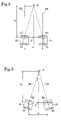
- FIG. 2is a schematic view of right and left photographing optical systems having substantially parallel photographing optical axes, in a stereo camera according to a first embodiment of the present invention
- FIG. 3is a schematic view of right and left photographing optical systems whose optical axes define therebetween an angle of convergence, in a stereo camera according to a first embodiment of the present invention
- FIG. 4is a perspective view of right and left photographing units and a drive mechanism thereof, in a stereo camera according to a first embodiment of the present invention
- FIGS. 5A and 5Bschematically show a plan view and a front elevational view, of right and left photographing units and a drive mechanism thereof, shown in FIG. 4 ;
- FIG. 6is a block diagram of a circuit construction in a stereo camera according to a first embodiment of the present invention.
- FIG. 7is a flow chart of a photographing operation of a stereo camera according to a first embodiment of the present invention.
- FIG. 8is a perspective view of a second embodiment of a stereo camera according to the present invention.
- FIG. 9is a schematic view of right and left photographing optical systems having substantially parallel photographing optical axes, in a stereo camera according to a second embodiment of the present invention.
- FIG. 10is a schematic view of right and left photographing optical systems whose optical axes define therebetween an angle of convergence, in a stereo camera according to a second embodiment of the present invention.
- FIG. 11is a block diagram of a circuitry in a stereo camera according to a second embodiment of the present invention.
- FIG. 12is a flow chart of a photographing operation of a stereo camera according to a second embodiment of the present invention.
- FIG. 13is a perspective view of a third embodiment of a stereo camera according to the present invention.
- FIG. 14is a schematic view of right and left photographing optical systems having substantially parallel photographing optical axes, in a stereo camera according to a third embodiment of the present invention.
- FIG. 15is a schematic view of right and left photographing optical systems whose optical axes define therebetween an angle of convergence, in a stereo camera according to a third embodiment of the present invention.
- FIG. 16is a block diagram of a circuit construction in a stereo camera according to a third embodiment of the present invention.
- FIG. 17is a flow chart of a photographing operation of a stereo camera according to a third embodiment of the present invention.
- FIG. 1shows a first embodiment of a stereo camera according to the present invention.
- the stereo camera 10is an electronic still camera in which an object is photographed using an image pickup device and is comprised of a box-shaped housing 11 which is provided on the front portion thereof with a pair of right and left photographing optical systems RL and LL and on the rear portion thereof with a pair of right and left finder eyepiece portions RF and LF.
- the housing 11is provided on its upper surface with a function dial 12 which is adapted to turn the power source ON/OFF or select photographing modes, and a release button 13 .
- a pair of operation buttons 14 and 15are provided in the vicinity of the function dial 12 to select the frames or exposure correction value, etc.
- an active type infrared object distance metering device 16is provided on the front surface of the housing 11 and between the right and left photographing optical systems RL and LL.
- the right photographing optical system RLis secured to a right photographing unit 21 in the form of a box.
- the left photographing optical system LLis secured to a left photographing unit 22 in the form of a box.
- the photographing optical systems RL and LLare each provided with an AF lens (not shown) movable along the optical axis.
- the pair of photographing units 21 and 22 in a symmetric arrangement in the lateral directionare identical in structure.
- a right CCD (first image pickup device) 23is provided in the photographing unit 21 behind the photographing optical system RL to pickup an object image formed by the photographing optical system RL.
- a left CCD (second image pickup device) 24is provided in the photographing unit 22 behind the photographing optical system LL to pickup an object image formed by the photographing optical system LL.
- the right and left photographing optical systems RL and LLare spaced at a distance equal to the base length d with respect to the center point P.
- a right LCD 17 R in which an object image picked-up by the right CCD 23 is indicatedis built in the right finder eyepiece portion RF (see FIG. 6 ).
- a left LCD 17 L in which an object image picked-up by the left CCD 24 is indicatedis built in the left finder eyepiece portion LF (see FIG. 6 ).
- the right and left photographing units 21 and 22are secured to rotary plates 31 and 32 whose center axes of rotation C 1 and C 2 are parallel. As shown in FIGS. 5A and 5B , the center axes C 1 and C 2 of the rotary plates 31 and 32 pass substantially through the centers of the corresponding photographing optical systems RL and LL and extend in the direction perpendicular to the optical axes OR and OL, respectively.
- the rotary plates 31 and 32are provided with sector gears 31 a and 32 a which are always in mesh with each other. Consequently, the right and left rotary plates 31 and 32 are rotatable in opposite directions in association with each other through the sector gears 31 a and 32 a.
- the rotary plate 32 to which the left photographing unit 22 is securedis provided with a sector worm wheel 32 b on the side opposite to the sector gear 32 a with respect to the center of rotation C 2 .
- the worm wheel 32 bis always in mesh with a worm 35 a secured to a drive shaft of a motor 35 provided in the vicinity of the rotary plate 32 .
- the diameter L 1 of the gear portion 31 ais identical to the diameter L 2 of the gear portion 32 a
- the diameter L 3 of the worm wheel 32 bis larger than the diameter L 1 (L 2 ).
- the rotary plates 31 , 32 , the gear portions 31 a , 32 a , the worm wheel 32 b , the worm 35 a , and the motor 35 , etc.,form a drive mechanism which constitutes a convergence angle adjustment mechanism 45 ( FIG. 6 ).
- the optical axes OR and OL of the right and left photographing units 21 and 22are substantially parallel, i.e., the right and left photographing optical systems RL and LL have no angle of convergence.
- the optical axes OR and OL of the right and left photographing units 21 and 22intersect at a point in front of the stereo camera 10 , i.e., the right and left photographing optical systems RL and LL define an angle of convergence therebetween.
- “d”designates the base length
- “S”the main object
- “f o ”the object distance
- ⁇a half angle of convergence (i.e., 2 ⁇ represents the angle of convergence)
- Pthe origin located at the median point of the right and left photographing optical systems RL and LL, respectively.
- FIG. 6shows a block diagram of a circuit of the stereo camera 10 according to the first embodiment.
- the stereo camera 10has a system controller (control circuit) 40 in the form of a microcomputer, etc., for generally controlling the camera 10 .
- a system controller (control circuit) 40in the form of a microcomputer, etc., for generally controlling the camera 10 .
- Connected to the controller 40are a release switch 13 a which is turned ON/OFF in accordance with the operation of the release button 13 , operation switches 14 a and 15 a which are respectively turned ON/OFF by the operation of the operation switches 14 and 15 , and a function dial switch 12 a whose state is varied in accordance with the operation of the function dial 12 .
- the release switch 13 ais a two-step switch which detects half depression and full depression of the release button 13 .
- An object distance measuring device 16a first lens drive circuit 41 which drives the AF lens of the right photographing optical system RL, a second lens drive circuit 42 which drives the AF lens of the left photographing optical system LL, a first CCD drive circuit 43 which drives the right CCD 23 , a second CCD drive circuit 44 which drives the left CCD 24 , and a convergence angle adjustment mechanism 45 are connected to the system controller 40 .
- a first LCD drive circuit 46 which drives the right LCD 17 R and a second LCD drive circuit 47 which drives the left LCD 17 Lare connected to the system controller 40 .
- An image recording device 55which records image data in a recording medium (not shown) such as a floppy disc or a flash memory, etc., is connected to the memory controller 54 .
- the image signal obtained through the right CCD 23is subject to an A/D conversion by the first A/D converter 50 through the first CDS/AGC circuit 48 and is stored in the memory 52 .
- the image signal obtained through the left CCD 24is subject to an A/D conversion by the second A/D converter 51 through the second CDS/AGC circuit 49 and is stored in the memory 52 .
- the image signals stored in the memory 52are processed by the signal processor 53 and are fed to the right LCD 17 R and the left LCD 17 L.
- the signal processor 53sends the same image signal as those fed to the right and left LCDs 17 R and 17 L to the memory controller 54 .
- the image signal fed to the memory controller 54is recorded on a recording medium such as a floppy disc or a flash memory, etc., by the image memory device 55 as image data when the release button 13 is depressed to turn the release switch 13 a ON.
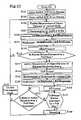
- FIG. 7shows a flow chart of the photographing operation in the stereo camera 10 according to the first embodiment.
- the right and left CCDs 23 and 24are driven, and the right and left LCDs 17 R and 17 L are driven (S 101 , S 103 ).
- a passive object distance measurementis carried out in each of the right and left CCD 23 and 24 (S 105 ).
- the measurement point for the right CCD 23is located in the left side area of the field angle (e.g., substantially at the center of the left half of the field angle) with respect to the median line thereof.
- the measurement point for the left CCD 24is located in the right side area of the field angle (e.g., substantially at the center of the right half of the field angle) with respect to the median line thereof.
- the photometering operation(brightness measurement) is carried out in each of the right and left CCDs 23 and 24 (S 107 ). Thereafter, a mean value of the first measurement (first object distance) obtained by the right CCD 23 and the second measurement (second object distance) obtained by the left CCD 24 is calculated ([1st object distance+2nd object distance]/2). Subsequently, a mean value of the first photometering measurement (first brightness) obtained by the right CCD 23 and the second photometering measurement (second brightness) obtained by the left CCD 24 is calculated ([1st brightness+2nd brightness]/2) (S 109 , S 111 ). Consequently, the AE/AF control operations are carried out in accordance with the mean object distance obtained at step S 109 and the mean brightness obtained at step S 111 (S 113 ).
- step S 115If it is detected that the release button 13 is depressed by half a step (S 115 ), the control proceeds to step S 117 . If it is not detected that the release button 13 is depressed by half a step, the control is returned to step S 105 . Namely, the operations from step S 105 to step S 115 are repeated so long as the release button 13 is not depressed by half a step after the power source is turned ON.
- the active measurement of the object distanceis carried out by the object distance measuring device 16 to obtain the object distance f o . Consequently, the convergence angle adjustment mechanism 45 (i.e., the motor 35 ) is driven in accordance with the object distance to provide an angle of convergence between the right and left optical axes OR and OL (S 117 , S 119 ).
- the measurements of the brightnessare carried out again in the right and left CCDs 23 and 24 , similar to those at step S 107 .
- a mean value of the first measurement (first brightness) obtained by the right CCD 23 and the second measurement (second brightness) obtained by the left CCD 24is calculated in accordance with ([1st brightness+2nd brightness]/2) (S 121 , S 123 ). Consequently, the AE control is carried out in accordance with the mean brightness thus obtained (S 125 ).
- step S 129If it is detected that the release button 13 is depressed by a full step, the control proceeds to step S 129 . If it is not detected that the release button 13 is depressed by a full step, the control proceeds to step S 131 (S 127 ). If the release button 13 is depressed by a full step, the memory controller 54 and the image recorder 55 are driven to record the image data in the recording medium (not shown), such as a floppy disc or a flash memory (S 129 ). After the recording operation is completed, the angle of convergence is returned to a predetermined initial value and the control is returned (S 133 ).
- step S 127If it is detected at step S 127 that the release button 13 is not depressed by a full step, it is checked whether the release button 13 has been released from a half step depression (S 131 ). If it is detected that the half depression of the release button 13 is not released, (i.e., the half depression of the release button 13 is maintained), the control is returned to step S 127 to repeat steps 127 and S 131 . If it is detected that the half depression of the release button 13 is released, the control proceeds to step S 133 (S 131 : Y; S 133 ).
- ⁇represents the half angle of convergence (degrees)
- f orepresents the object distance (m)
- drepresents the base length (mm) between the right and left photographing optical systems RL and LL.
- the object distance f ois determined at step S 117 in FIG. 7 .
- FIG. 8shows a second embodiment of a stereo camera according to the present invention.
- the stereo camera 100is an electronic still camera similar to the stereo camera 10 in the first embodiment.
- the camera 100includes a box-like housing 101 which is provided on the front surface thereof with right and left photographing optical systems RL and LL, and on the rear surface thereof with right and left finder eyepiece portions RF and LF, respectively.
- elements corresponding to those in the first embodimentare designated with like numerals.
- variable angle prisms(prisms whose apex angle is variable) RV and LV (see FIG. 9 ) are provided in each light path of the right and left photographing optical systems RL and LL, so that the variable angle prisms are driven to vary the angle of convergence, in the second embodiment.
- the right and left photographing units 21 and 22are secured to the box-like housing 101 in the second embodiment.
- the stereo camera 100is provided with variable angle prisms RV and LV on the object sides of the right and left photographing optical systems RL and LL (see FIGS. 9 and 10 ).
- no angle of convergenceis provided by the variable angle prisms Rv and LV, i.e., the optical axes OR and OL of the right and left photographing units 21 and 22 are parallel.
- an angle of convergenceis provided by the variable angle prisms RV and LV.
- “ ⁇ ”represents the variable apex angle (°) of the variable angle prisms RV and LV.
- FIG. 11shows a block diagram of a circuit in a stereo camera 100 according to the second embodiment.
- the convergence angle adjustment mechanism 45 provided in the circuit of the stereo camera 10 in the first embodimentis replaced with a variable angle prism (VAP) control apparatus 60 connected between the variable angle prisms RV, LV and the system controller (control circuit) 40 .
- the VAP control apparatus 60is controlled by the system controller 40 and drives the variable angle prisms RV and LV in accordance with the object distance f o obtained to vary the apex angle ⁇ of the variable angle prisms RV and LV.
- Other circuit elements in the second embodimentare the same as those of the circuit in the first embodiment shown in FIG. 6 .
- the variable angle prisms RV, LV and the VAP control apparatus 60constitute the convergence angle adjustment mechanism.
- FIG. 12shows a flow chart of the photographing operation of the stereo camera 100 according to the second embodiment.
- the operation at step S 119 in the flow chart of the photographing operation of the stereo camera 10 according to the first embodiment shown in FIG. 7is replaced with the variable angle prism (VAP) control operation (S 118 ).
- VAPvariable angle prism
- variable angle prisms RV and LVare driven to vary the apex angles ⁇ of the variable angle prisms RV and LV, so that a desired angle of convergence can be provided between the right and left optical axes OR and OL (S 118 ). Thereafter, the control proceeds to step S 121 .
- ⁇represents the variable apex angle (°)
- nrepresents the refractive index of the variable angle prisms RV and LV
- ⁇represents half of the convergence angle (deflection angle) (°), respectively.
- Table 2shows a relationship between the object distance f o and the variable apex angle ⁇ when the base length d is 65 mm and the refractive index n is 1.5, respectively, in the stereo camera 100 according to the second embodiment.
- FIG. 13shows a third embodiment of a stereo camera according to the present invention.
- the stereo camera 200is an electronic still camera similar to the stereo camera 10 in the first embodiment.
- the camera 200includes a box-like housing 101 which is provided on the front surface thereof with a pair of right and left photographing optical systems RL and LL, and on the rear surface thereof with a pair of right and left finder eyepiece portions RF and LF, respectively.
- elements corresponding to those in the first embodimentare designated with the same reference designators.
- the right and left photographing optical systems RL and LLare shifted (decentered) in a direction of the base length thereof to vary the angle of convergence.
- the right and left photographing optical systems RL and LLare movable in the lateral direction (right and left direction in FIGS. 14 and 15 ) to move away from or close to each other within the corresponding photographing units 21 and 22 , in the stereo camera 200 .
- first and second lens shift actuators (lens drive mechanisms) 61 and 62FIG.
- the drive mechanism 16are provided to move the right and left photographing optical systems RL and LL in the directions away from or close to each other.
- the drive mechanismcan be achieved by any known drive mechanism, for example, a combination of a motor and a cam mechanism or an electromagnetic drive mechanism having a coil combined with a magnet.
- the shift (off-axis amount) of the photographing optical systems RL and LL from the CCDs 23 and 24 in the photographing units 21 and 22is zero, and hence no angle of convergence is provided (i.e., the optical axes OR and OL of the right and left photographing units 21 and 22 are parallel).
- the photographing optical systems RL and LLare shifted by y (mm) from the CCDs 23 and 24 in the photographing units 21 and 22 , so that a predetermined angle of convergence is provided.
- “ ⁇ ”represents half of the angle of convergence (°)
- “f”represents the focal length of the lens (mm)
- y”represents the shift amount (mm) of the photographing optical systems RL and LL, respectively.
- FIG. 16shows a block diagram of a circuit in a stereo camera 200 according to the third embodiment.
- the convergence angle adjustment mechanism 45 provided in the circuit of the stereo camera 10 in the first embodimentis replaced with a first lens shift actuator 61 which is connected between the right photographing optical system RL and the system controller 40 , and a second lens shift actuator 62 which is connected between the left photographing optical system LL and the system controller 40 .
- the first lens shift actuator 61is controlled by the system controller 40 to move the right photographing optical system RL by the amount of shift (displacement) “y” in accordance with the object distance “f o ” obtained.
- the second lens shift actuator 62is controlled by the system controller 40 to move the left photographing optical system LL by the amount of shift (displacement) “y” in accordance with the object distance “f o ” obtained.
- Other circuit elements in the third embodimentare the same as those of the circuit in the first embodiment shown in FIG. 6 .
- the first lens shift actuator 61 and the second lens shift actuator 62 , etc.constitute a convergence angle adjustment mechanism.
- FIG. 17shows a flow chart of the photographing operation of the stereo camera 200 according to the third embodiment.
- the operations at steps S 119 and S 133 in the flow chart of the photographing operation of the stereo camera 10 according to the first embodiment shown in FIG. 7are replaced with lens shift actuator control operation (S 120 ) and the return operation of the lenses (photographing optical systems RL and LL) to the initial positions (S 134 ), respectively.
- Other operations in FIG. 17are the same as those in FIG. 7 .
- step S 117the lens shift actuators 61 and 62 are driven in accordance with the object distance thus obtained to move or shift the photographing optical systems RL and LL (S 120 ). Thereafter, the control proceeds to step S 121 .
- step S 134the photographing optical systems RL and LL are returned to the preset initial positions and thereafter, the control is returned to step S 105 .
- yrepresents the amount of shift (displacement) (mm)
- frepresents the focal length of the lens (mm)
- ⁇represents half of the convergence angle (°)
- drepresents the base length between the right and left photographing optical systems RL and LL, respectively.
- variable angle prisms RV and LVare provided on the object sides of the right and left photographing optical systems RL and LL in the second embodiment
- the arrangement of the variable angle prismsis not limited thereto. Namely, the variable angle prisms can be located at any positions within the light paths of the right and left photographing optical systems RL and LL. For instance, the same technical effect can be expected from an alternative arrangement in which the variable angle prisms RV and LV are provided within the corresponding photographing optical systems RL and LL.
- the right and left photographing optical systems RL and LLare moved with respect to the optical axes OR and OL thereof in the directions perpendicular to the optical axes to vary the angle of convergence
- the inventionis not limited thereto.
- the same effect as the previous embodimentscan be obtained.
- the present inventioncan be equally applied to a stereo camera using silver halide films which replace the CCDs 23 and 24 , respectively.
- the convergence angle adjustment mechanismis automatically controlled to vary the angle of convergence defined between the optical axes of a pair of photographing optical systems to adjust the photographic coverage of the pair of photographic optical systems so as to coincide with each other, in accordance with the object distance data, it is possible to easily set an appropriate angle of convergence between the right and left optical axes without need of a complex operation to thereby obtain a high-quality three-dimensional picture, even if the object distance is relatively small or the telephotographic photographing systems are used.
Landscapes
- Engineering & Computer Science (AREA)
- Multimedia (AREA)
- Signal Processing (AREA)
- Physics & Mathematics (AREA)
- General Physics & Mathematics (AREA)
- Stereoscopic And Panoramic Photography (AREA)
- Testing, Inspecting, Measuring Of Stereoscopic Televisions And Televisions (AREA)
- Focusing (AREA)
- Cameras In General (AREA)
- Automatic Focus Adjustment (AREA)
- Studio Devices (AREA)
Abstract
Description
θ=tan−1(d/2fo) (1)
| TABLE 1 | |||
| fo (m) | θ (°) | ||
| 1 | 1.861 | ||
| 2 | 0.931 | ||
| 5 | 0.372 | ||
| 10 | 0.186 | ||
Φ=(n−1)θ (2)
| TABLE 2 | |||
| fo (m) | Φ (°) | ||
| 1 | 0.931 | ||
| 2 | 0.466 | ||
| 5 | 0.186 | ||
| 10 | 0.093 | ||
y=f·tan ω (3)
tan ω=0.5d/(fo+f)
Claims (7)
Applications Claiming Priority (1)
| Application Number | Priority Date | Filing Date | Title |
|---|---|---|---|
| JP19310799AJP4428761B2 (en) | 1999-07-07 | 1999-07-07 | Stereo camera |
Publications (1)
| Publication Number | Publication Date |
|---|---|
| US7190389B1true US7190389B1 (en) | 2007-03-13 |
Family
ID=16302372
Family Applications (1)
| Application Number | Title | Priority Date | Filing Date |
|---|---|---|---|
| US09/611,364Expired - Fee RelatedUS7190389B1 (en) | 1999-07-07 | 2000-07-06 | Stereo camera |
Country Status (2)
| Country | Link |
|---|---|
| US (1) | US7190389B1 (en) |
| JP (1) | JP4428761B2 (en) |
Cited By (46)
| Publication number | Priority date | Publication date | Assignee | Title |
|---|---|---|---|---|
| US20040046885A1 (en)* | 2002-09-05 | 2004-03-11 | Eastman Kodak Company | Camera and method for composing multi-perspective images |
| US20040141064A1 (en)* | 2003-01-16 | 2004-07-22 | Masayuki Ezawa | Information terminal device |
| US20060227209A1 (en)* | 2005-04-08 | 2006-10-12 | Tomohiko Takayama | Image display apparatus and control method thereof |
| US20060274188A1 (en)* | 2005-06-03 | 2006-12-07 | Cedar Crest Partners, Inc. | Multi-dimensional imaging system and method |
| US20070160360A1 (en)* | 2005-12-15 | 2007-07-12 | Mediapod Llc | System and Apparatus for Increasing Quality and Efficiency of Film Capture and Methods of Use Thereof |
| US20070181686A1 (en)* | 2005-10-16 | 2007-08-09 | Mediapod Llc | Apparatus, system and method for increasing quality of digital image capture |
| US20080024614A1 (en)* | 2006-07-25 | 2008-01-31 | Hsiang-Tsun Li | Mobile device with dual digital camera sensors and methods of using the same |
| US20090041338A1 (en)* | 2007-08-09 | 2009-02-12 | Fujifilm Corporation | Photographing field angle calculation apparatus |
| US20100238272A1 (en)* | 2009-03-23 | 2010-09-23 | James Cameron | Stereo Camera with Automatic Control of Interocular Distance |
| ITTO20090256A1 (en)* | 2009-04-03 | 2010-10-04 | Univ Degli Studi Torino | STEREOSCOPIC RECOVERY SYSTEM |
| US20100328499A1 (en)* | 2009-06-26 | 2010-12-30 | Flight Landata, Inc. | Dual-Swath Imaging System |
| US20110085788A1 (en)* | 2009-03-24 | 2011-04-14 | Vincent Pace | Stereo Camera Platform and Stereo Camera |
| US20110102552A1 (en)* | 2009-11-02 | 2011-05-05 | Gm Global Technology Operations, Inc. | On-vehicle three-dimensional video system and method of monitoring the surrounding environment of a vehicle using the same |
| US20110149045A1 (en)* | 2008-04-29 | 2011-06-23 | Alexander Wuerz-Wessel | Camera and method for controlling a camera |
| US20110150453A1 (en)* | 2009-12-22 | 2011-06-23 | Hon Hai Precision Industry Co., Ltd. | Three-dimensional camera module |
| US20110157387A1 (en)* | 2009-12-30 | 2011-06-30 | Samsung Electronics Co., Ltd. | Method and apparatus for generating image data |
| WO2011123701A1 (en)* | 2010-03-31 | 2011-10-06 | Waterdance, Inc. | Single seat-kill camera system |
| WO2011123455A1 (en)* | 2010-03-31 | 2011-10-06 | Waterdance, Inc. | Stereo camera with preset modes |
| EP2400765A1 (en)* | 2010-06-22 | 2011-12-28 | Sony Ericsson Mobile Communications AB | Stereoscopic image capturing apparatus, method and computer program |
| US20120002958A1 (en)* | 2010-07-01 | 2012-01-05 | Nokia Corporation | Method And Apparatus For Three Dimensional Capture |
| US20120027392A1 (en)* | 2010-07-28 | 2012-02-02 | Panasonic Corporation | Three-dimensional image pickup apparatus and three-dimensional image pickup method |
| EP2429178A1 (en)* | 2010-09-09 | 2012-03-14 | Sony Corporation | 3-D image pickup apparatus |
| CN102550015A (en)* | 2010-06-30 | 2012-07-04 | 富士胶片株式会社 | Multi-viewpoint imaging control device, multi-viewpoint imaging control method and multi-viewpoint imaging control program |
| US8355627B2 (en) | 2010-03-31 | 2013-01-15 | James Cameron & Vincent Pace | 3D camera with foreground object distance sensing |
| US20130033584A1 (en)* | 2010-04-12 | 2013-02-07 | Ja-Won Seo | Stereo camera module apparatus and method |
| USD680142S1 (en)* | 2011-07-26 | 2013-04-16 | Seegrid Corporation | Multi-camera head |
| US8456518B2 (en) | 2010-03-31 | 2013-06-04 | James Cameron & Vincent Pace | Stereoscopic camera with automatic obstruction removal |
| US20130141541A1 (en)* | 2010-06-11 | 2013-06-06 | Hysonic. Co., Ltd. | Compact camera actuator and compact stereo-scopic image photographing device |
| CN103163615A (en)* | 2011-12-14 | 2013-06-19 | 鸿富锦精密工业(深圳)有限公司 | Dual shot device |
| US20130208108A1 (en)* | 2012-02-10 | 2013-08-15 | Hon Hai Precision Industry Co., Ltd. | Parallax based distance measuring device |
| CN103256917A (en)* | 2012-02-15 | 2013-08-21 | 鸿富锦精密工业(深圳)有限公司 | Stereo visual system applicable to distance measurement |
| US20130265394A1 (en)* | 2010-12-16 | 2013-10-10 | Haekeun Lim | 3d stereoscopic camera module |
| US8754961B2 (en)* | 2011-08-17 | 2014-06-17 | Nokia Corporation | Apparatus and method for generating image data from overlapping regions of images |
| WO2014197109A3 (en)* | 2013-03-22 | 2015-04-30 | Seiko Epson Corporation | Infrared video display eyewear |
| US20150256814A1 (en)* | 2006-06-13 | 2015-09-10 | Billy D. Newbery | Digital Stereo Photographic System |
| RU2565855C1 (en)* | 2011-08-15 | 2015-10-20 | Кэнон Кабусики Кайся | Image capturing device, method of controlling said device and programme |
| US9174351B2 (en) | 2008-12-30 | 2015-11-03 | May Patents Ltd. | Electric shaver with imaging capability |
| US9544574B2 (en) | 2013-12-06 | 2017-01-10 | Google Inc. | Selecting camera pairs for stereoscopic imaging |
| US9565416B1 (en) | 2013-09-30 | 2017-02-07 | Google Inc. | Depth-assisted focus in multi-camera systems |
| US9965856B2 (en) | 2013-10-22 | 2018-05-08 | Seegrid Corporation | Ranging cameras using a common substrate |
| US10574871B2 (en)* | 2015-03-18 | 2020-02-25 | Gopro, Inc. | Camera and lens assembly |
| US10659763B2 (en) | 2012-10-09 | 2020-05-19 | Cameron Pace Group Llc | Stereo camera system with wide and narrow interocular distance cameras |
| EP3879337A1 (en)* | 2020-03-10 | 2021-09-15 | Cognex Corporation | Modular vision system and methods |
| US11721712B2 (en) | 2018-08-31 | 2023-08-08 | Gopro, Inc. | Image capture device |
| US20230418023A1 (en)* | 2022-06-23 | 2023-12-28 | Evident Corporation | Endoscope device, endoscope system, convergence angle changing method, and computer-readable medium |
| US12439140B2 (en) | 2023-04-11 | 2025-10-07 | Gopro, Inc. | Integrated sensor-lens assembly alignment in image capture systems |
Families Citing this family (3)
| Publication number | Priority date | Publication date | Assignee | Title |
|---|---|---|---|---|
| JP2007288229A (en)* | 2004-08-09 | 2007-11-01 | Sharp Corp | Image shooting device |
| JP2007140273A (en)* | 2005-11-21 | 2007-06-07 | Fujifilm Corp | Multifocal camera housing |
| KR101700360B1 (en) | 2010-03-04 | 2017-01-26 | 삼성전자주식회사 | Digital photographing apparatus, method for controlling the apparatus, and medium for recording the method |
Citations (20)
| Publication number | Priority date | Publication date | Assignee | Title |
|---|---|---|---|---|
| US4818858A (en)* | 1984-10-25 | 1989-04-04 | Canon Kabushiki Kaisha | Visual sensor system for producing stereoscopic visual information |
| US5420438A (en)* | 1992-10-29 | 1995-05-30 | Asahi Kogaku Kogyo Kabushiki Kaisha | Focus detecting apparatus including movement of detecting zones |
| US5570150A (en) | 1993-08-30 | 1996-10-29 | Asahi Kogaku Kogyo Kabushiki Kaisha | Stereo photographing system |
| US5581314A (en) | 1993-12-21 | 1996-12-03 | Asahi Kogaku Kogyo Kabushiki Kaisha | Camera with stereoscopic optical system |
| US5652926A (en)* | 1993-12-15 | 1997-07-29 | Fuji Photo Optical Co., Ltd. | Distance measuring apparatus |
| US5668595A (en)* | 1992-03-23 | 1997-09-16 | Canon Kabushiki Kaisha | Multi-lens imaging apparatus having a mechanism for combining a plurality of images without displacement of registration |
| EP0830034A1 (en) | 1996-09-11 | 1998-03-18 | Canon Kabushiki Kaisha | Processing of image obtained by multi-eye camera |
| US5748998A (en)* | 1994-10-13 | 1998-05-05 | Fuji Photo Optical Co., Ltd. | Camera |
| JPH10155104A (en) | 1996-11-22 | 1998-06-09 | Canon Inc | Compound eye imaging method and apparatus, and storage medium |
| US5819016A (en)* | 1993-10-05 | 1998-10-06 | Kabushiki Kaisha Toshiba | Apparatus for modeling three dimensional information |
| US5864360A (en)* | 1993-08-26 | 1999-01-26 | Canon Kabushiki Kaisha | Multi-eye image pick-up apparatus with immediate image pick-up |
| US5870178A (en)* | 1996-02-20 | 1999-02-09 | Canon Kabushiki Kaisha | Distance measuring apparatus |
| US5883662A (en)* | 1995-06-06 | 1999-03-16 | Zanen; Pieter O. | Apparatus for three-dimensional measurement and imaging having focus-related convergance compensation |
| US5889553A (en)* | 1993-11-17 | 1999-03-30 | Canon Kabushiki Kaisha | Image pickup apparatus capable of high resolution imaging |
| US5990943A (en)* | 1992-10-16 | 1999-11-23 | Canon Kabushiki Kaisha | Optical apparatus with a plurality of zooming control means |
| US6041186A (en)* | 1997-05-27 | 2000-03-21 | Asahi Kogaku Kogyo Kabushiki Kaish | Finder system |
| US6326994B1 (en)* | 1997-01-22 | 2001-12-04 | Sony Corporation | Matched field-of-view stereographic imaging apparatus |
| US6385334B1 (en)* | 1998-03-12 | 2002-05-07 | Fuji Jukogyo Kabushiki Kaisha | System and method for adjusting stereo camera |
| US6449004B1 (en)* | 1996-04-23 | 2002-09-10 | Minolta Co., Ltd. | Electronic camera with oblique view correction |
| US6507359B1 (en)* | 1993-09-20 | 2003-01-14 | Canon Kabushiki Kaisha | Image display system |
- 1999
- 1999-07-07JPJP19310799Apatent/JP4428761B2/ennot_activeExpired - Fee Related
- 2000
- 2000-07-06USUS09/611,364patent/US7190389B1/ennot_activeExpired - Fee Related
Patent Citations (20)
| Publication number | Priority date | Publication date | Assignee | Title |
|---|---|---|---|---|
| US4818858A (en)* | 1984-10-25 | 1989-04-04 | Canon Kabushiki Kaisha | Visual sensor system for producing stereoscopic visual information |
| US5668595A (en)* | 1992-03-23 | 1997-09-16 | Canon Kabushiki Kaisha | Multi-lens imaging apparatus having a mechanism for combining a plurality of images without displacement of registration |
| US5990943A (en)* | 1992-10-16 | 1999-11-23 | Canon Kabushiki Kaisha | Optical apparatus with a plurality of zooming control means |
| US5420438A (en)* | 1992-10-29 | 1995-05-30 | Asahi Kogaku Kogyo Kabushiki Kaisha | Focus detecting apparatus including movement of detecting zones |
| US5864360A (en)* | 1993-08-26 | 1999-01-26 | Canon Kabushiki Kaisha | Multi-eye image pick-up apparatus with immediate image pick-up |
| US5570150A (en) | 1993-08-30 | 1996-10-29 | Asahi Kogaku Kogyo Kabushiki Kaisha | Stereo photographing system |
| US6507359B1 (en)* | 1993-09-20 | 2003-01-14 | Canon Kabushiki Kaisha | Image display system |
| US5819016A (en)* | 1993-10-05 | 1998-10-06 | Kabushiki Kaisha Toshiba | Apparatus for modeling three dimensional information |
| US5889553A (en)* | 1993-11-17 | 1999-03-30 | Canon Kabushiki Kaisha | Image pickup apparatus capable of high resolution imaging |
| US5652926A (en)* | 1993-12-15 | 1997-07-29 | Fuji Photo Optical Co., Ltd. | Distance measuring apparatus |
| US5581314A (en) | 1993-12-21 | 1996-12-03 | Asahi Kogaku Kogyo Kabushiki Kaisha | Camera with stereoscopic optical system |
| US5748998A (en)* | 1994-10-13 | 1998-05-05 | Fuji Photo Optical Co., Ltd. | Camera |
| US5883662A (en)* | 1995-06-06 | 1999-03-16 | Zanen; Pieter O. | Apparatus for three-dimensional measurement and imaging having focus-related convergance compensation |
| US5870178A (en)* | 1996-02-20 | 1999-02-09 | Canon Kabushiki Kaisha | Distance measuring apparatus |
| US6449004B1 (en)* | 1996-04-23 | 2002-09-10 | Minolta Co., Ltd. | Electronic camera with oblique view correction |
| EP0830034A1 (en) | 1996-09-11 | 1998-03-18 | Canon Kabushiki Kaisha | Processing of image obtained by multi-eye camera |
| JPH10155104A (en) | 1996-11-22 | 1998-06-09 | Canon Inc | Compound eye imaging method and apparatus, and storage medium |
| US6326994B1 (en)* | 1997-01-22 | 2001-12-04 | Sony Corporation | Matched field-of-view stereographic imaging apparatus |
| US6041186A (en)* | 1997-05-27 | 2000-03-21 | Asahi Kogaku Kogyo Kabushiki Kaish | Finder system |
| US6385334B1 (en)* | 1998-03-12 | 2002-05-07 | Fuji Jukogyo Kabushiki Kaisha | System and method for adjusting stereo camera |
Cited By (130)
| Publication number | Priority date | Publication date | Assignee | Title |
|---|---|---|---|---|
| US20040046885A1 (en)* | 2002-09-05 | 2004-03-11 | Eastman Kodak Company | Camera and method for composing multi-perspective images |
| US7466336B2 (en)* | 2002-09-05 | 2008-12-16 | Eastman Kodak Company | Camera and method for composing multi-perspective images |
| US20040141064A1 (en)* | 2003-01-16 | 2004-07-22 | Masayuki Ezawa | Information terminal device |
| US7397511B2 (en) | 2003-01-16 | 2008-07-08 | Sharp Kabushiki Kaisha | Information terminal device |
| US20060227209A1 (en)* | 2005-04-08 | 2006-10-12 | Tomohiko Takayama | Image display apparatus and control method thereof |
| US7940295B2 (en)* | 2005-04-08 | 2011-05-10 | Canon Kabushiki Kaisha | Image display apparatus and control method thereof |
| US20060274188A1 (en)* | 2005-06-03 | 2006-12-07 | Cedar Crest Partners, Inc. | Multi-dimensional imaging system and method |
| US8194168B2 (en)* | 2005-06-03 | 2012-06-05 | Mediapod Llc | Multi-dimensional imaging system and method |
| US8599297B2 (en) | 2005-06-03 | 2013-12-03 | Cedar Crest Partners Inc. | Multi-dimensional imaging system and method |
| US9167154B2 (en) | 2005-06-21 | 2015-10-20 | Cedar Crest Partners Inc. | System and apparatus for increasing quality and efficiency of film capture and methods of use thereof |
| US8767080B2 (en) | 2005-08-25 | 2014-07-01 | Cedar Crest Partners Inc. | System and apparatus for increasing quality and efficiency of film capture and methods of use thereof |
| US20090195664A1 (en)* | 2005-08-25 | 2009-08-06 | Mediapod Llc | System and apparatus for increasing quality and efficiency of film capture and methods of use thereof |
| US7864211B2 (en) | 2005-10-16 | 2011-01-04 | Mowry Craig P | Apparatus, system and method for increasing quality of digital image capture |
| US20070181686A1 (en)* | 2005-10-16 | 2007-08-09 | Mediapod Llc | Apparatus, system and method for increasing quality of digital image capture |
| US8319884B2 (en) | 2005-12-15 | 2012-11-27 | Mediapod Llc | System and apparatus for increasing quality and efficiency of film capture and methods of use thereof |
| US20070160360A1 (en)* | 2005-12-15 | 2007-07-12 | Mediapod Llc | System and Apparatus for Increasing Quality and Efficiency of Film Capture and Methods of Use Thereof |
| US20150256814A1 (en)* | 2006-06-13 | 2015-09-10 | Billy D. Newbery | Digital Stereo Photographic System |
| US8189100B2 (en)* | 2006-07-25 | 2012-05-29 | Qualcomm Incorporated | Mobile device with dual digital camera sensors and methods of using the same |
| US20080024614A1 (en)* | 2006-07-25 | 2008-01-31 | Hsiang-Tsun Li | Mobile device with dual digital camera sensors and methods of using the same |
| US20090041338A1 (en)* | 2007-08-09 | 2009-02-12 | Fujifilm Corporation | Photographing field angle calculation apparatus |
| US8326023B2 (en)* | 2007-08-09 | 2012-12-04 | Fujifilm Corporation | Photographing field angle calculation apparatus |
| US20110149045A1 (en)* | 2008-04-29 | 2011-06-23 | Alexander Wuerz-Wessel | Camera and method for controlling a camera |
| US10986259B2 (en) | 2008-12-30 | 2021-04-20 | May Patents Ltd. | Electric shaver with imaging capability |
| US10456934B2 (en) | 2008-12-30 | 2019-10-29 | May Patents Ltd. | Electric hygiene device with imaging capability |
| US11303791B2 (en) | 2008-12-30 | 2022-04-12 | May Patents Ltd. | Electric shaver with imaging capability |
| US11303792B2 (en) | 2008-12-30 | 2022-04-12 | May Patents Ltd. | Electric shaver with imaging capability |
| US11297216B2 (en) | 2008-12-30 | 2022-04-05 | May Patents Ltd. | Electric shaver with imaging capabtility |
| US11206343B2 (en) | 2008-12-30 | 2021-12-21 | May Patents Ltd. | Electric shaver with imaging capability |
| US11206342B2 (en) | 2008-12-30 | 2021-12-21 | May Patents Ltd. | Electric shaver with imaging capability |
| US11356588B2 (en) | 2008-12-30 | 2022-06-07 | May Patents Ltd. | Electric shaver with imaging capability |
| US11006029B2 (en) | 2008-12-30 | 2021-05-11 | May Patents Ltd. | Electric shaver with imaging capability |
| US10999484B2 (en) | 2008-12-30 | 2021-05-04 | May Patents Ltd. | Electric shaver with imaging capability |
| US11758249B2 (en) | 2008-12-30 | 2023-09-12 | May Patents Ltd. | Electric shaver with imaging capability |
| US10958819B2 (en) | 2008-12-30 | 2021-03-23 | May Patents Ltd. | Electric shaver with imaging capability |
| US11616898B2 (en) | 2008-12-30 | 2023-03-28 | May Patents Ltd. | Oral hygiene device with wireless connectivity |
| US11438495B2 (en) | 2008-12-30 | 2022-09-06 | May Patents Ltd. | Electric shaver with imaging capability |
| US10868948B2 (en) | 2008-12-30 | 2020-12-15 | May Patents Ltd. | Electric shaver with imaging capability |
| US10863071B2 (en) | 2008-12-30 | 2020-12-08 | May Patents Ltd. | Electric shaver with imaging capability |
| US10730196B2 (en) | 2008-12-30 | 2020-08-04 | May Patents Ltd. | Electric shaver with imaging capability |
| US10695922B2 (en) | 2008-12-30 | 2020-06-30 | May Patents Ltd. | Electric shaver with imaging capability |
| US10661458B2 (en) | 2008-12-30 | 2020-05-26 | May Patents Ltd. | Electric shaver with imaging capability |
| US11575817B2 (en) | 2008-12-30 | 2023-02-07 | May Patents Ltd. | Electric shaver with imaging capability |
| US11445100B2 (en) | 2008-12-30 | 2022-09-13 | May Patents Ltd. | Electric shaver with imaging capability |
| US9848174B2 (en) | 2008-12-30 | 2017-12-19 | May Patents Ltd. | Electric shaver with imaging capability |
| US11509808B2 (en) | 2008-12-30 | 2022-11-22 | May Patents Ltd. | Electric shaver with imaging capability |
| US12389092B1 (en) | 2008-12-30 | 2025-08-12 | May Patents Ltd. | Electric shaver with imaging capability |
| US10500741B2 (en) | 2008-12-30 | 2019-12-10 | May Patents Ltd. | Electric shaver with imaging capability |
| US11716523B2 (en) | 2008-12-30 | 2023-08-01 | Volteon Llc | Electric shaver with imaging capability |
| US10456933B2 (en) | 2008-12-30 | 2019-10-29 | May Patents Ltd. | Electric shaver with imaging capability |
| US12309468B2 (en) | 2008-12-30 | 2025-05-20 | May Patents Ltd. | Electric shaver with imaging capability |
| US12284428B2 (en) | 2008-12-30 | 2025-04-22 | May Patents Ltd. | Electric shaver with imaging capability |
| US12081847B2 (en) | 2008-12-30 | 2024-09-03 | May Patents Ltd. | Electric shaver with imaging capability |
| US12075139B2 (en) | 2008-12-30 | 2024-08-27 | May Patents Ltd. | Electric shaver with imaging capability |
| US10449681B2 (en) | 2008-12-30 | 2019-10-22 | May Patents Ltd. | Electric shaver with imaging capability |
| US10220529B2 (en) | 2008-12-30 | 2019-03-05 | May Patents Ltd. | Electric hygiene device with imaging capability |
| US11778290B2 (en) | 2008-12-30 | 2023-10-03 | May Patents Ltd. | Electric shaver with imaging capability |
| US11985397B2 (en) | 2008-12-30 | 2024-05-14 | May Patents Ltd. | Electric shaver with imaging capability |
| US9174351B2 (en) | 2008-12-30 | 2015-11-03 | May Patents Ltd. | Electric shaver with imaging capability |
| US11563878B2 (en) | 2008-12-30 | 2023-01-24 | May Patents Ltd. | Method for non-visible spectrum images capturing and manipulating thereof |
| US11570347B2 (en) | 2008-12-30 | 2023-01-31 | May Patents Ltd. | Non-visible spectrum line-powered camera |
| US9950435B2 (en) | 2008-12-30 | 2018-04-24 | May Patents Ltd. | Electric shaver with imaging capability |
| US9950434B2 (en) | 2008-12-30 | 2018-04-24 | May Patents Ltd. | Electric shaver with imaging capability |
| US11838607B2 (en) | 2008-12-30 | 2023-12-05 | May Patents Ltd. | Electric shaver with imaging capability |
| US11575818B2 (en) | 2008-12-30 | 2023-02-07 | May Patents Ltd. | Electric shaver with imaging capability |
| US11336809B2 (en) | 2008-12-30 | 2022-05-17 | May Patents Ltd. | Electric shaver with imaging capability |
| US11800207B2 (en) | 2008-12-30 | 2023-10-24 | May Patents Ltd. | Electric shaver with imaging capability |
| US8666241B2 (en) | 2009-03-23 | 2014-03-04 | Vincent Pace | Stereo camera with automatic control of interocular distance based on lens settings |
| US8406619B2 (en) | 2009-03-23 | 2013-03-26 | Vincent Pace & James Cameron | Stereo camera with automatic control of interocular distance |
| US20100238272A1 (en)* | 2009-03-23 | 2010-09-23 | James Cameron | Stereo Camera with Automatic Control of Interocular Distance |
| US20110085788A1 (en)* | 2009-03-24 | 2011-04-14 | Vincent Pace | Stereo Camera Platform and Stereo Camera |
| US8401381B2 (en) | 2009-03-24 | 2013-03-19 | Vincent Pace & James Cameron | Stereo camera platform and stereo camera |
| US8238741B2 (en) | 2009-03-24 | 2012-08-07 | James Cameron & Vincent Pace | Stereo camera platform and stereo camera |
| ITTO20090256A1 (en)* | 2009-04-03 | 2010-10-04 | Univ Degli Studi Torino | STEREOSCOPIC RECOVERY SYSTEM |
| US20100328499A1 (en)* | 2009-06-26 | 2010-12-30 | Flight Landata, Inc. | Dual-Swath Imaging System |
| US8462209B2 (en)* | 2009-06-26 | 2013-06-11 | Keyw Corporation | Dual-swath imaging system |
| US20110102552A1 (en)* | 2009-11-02 | 2011-05-05 | Gm Global Technology Operations, Inc. | On-vehicle three-dimensional video system and method of monitoring the surrounding environment of a vehicle using the same |
| CN102055956A (en)* | 2009-11-02 | 2011-05-11 | 通用汽车环球科技运作公司 | Vehicle-mounted three-dimensional video system and method for monitoring vehicle surrounding environment by using same |
| US8830318B2 (en) | 2009-11-02 | 2014-09-09 | GM Global Technology Operations LLC | On-vehicle three-dimensional video system and method of monitoring the surrounding environment of a vehicle using the same |
| US8195043B2 (en)* | 2009-12-22 | 2012-06-05 | Hon Hai Precision Industry Co., Ltd. | Three-dimensional camera module |
| US20110150453A1 (en)* | 2009-12-22 | 2011-06-23 | Hon Hai Precision Industry Co., Ltd. | Three-dimensional camera module |
| US20110157387A1 (en)* | 2009-12-30 | 2011-06-30 | Samsung Electronics Co., Ltd. | Method and apparatus for generating image data |
| US9019426B2 (en)* | 2009-12-30 | 2015-04-28 | Samsung Electronics Co., Ltd. | Method of generating image data by an image device including a plurality of lenses and apparatus for generating image data |
| EP2556409A4 (en)* | 2010-03-31 | 2014-08-13 | Cameron James | Stereo camera with preset modes |
| US8306415B2 (en) | 2010-03-31 | 2012-11-06 | Vincent Pace | Single seat-kill camera system |
| US8170413B2 (en) | 2010-03-31 | 2012-05-01 | James Cameron | Single seat-kill camera system |
| WO2011123701A1 (en)* | 2010-03-31 | 2011-10-06 | Waterdance, Inc. | Single seat-kill camera system |
| US8456518B2 (en) | 2010-03-31 | 2013-06-04 | James Cameron & Vincent Pace | Stereoscopic camera with automatic obstruction removal |
| CN103003750A (en)* | 2010-03-31 | 2013-03-27 | 詹姆斯·卡梅隆 | Stereo camera with preset modes |
| US8401380B2 (en) | 2010-03-31 | 2013-03-19 | Vincent Pace & James Cameron | Stereo camera with preset modes |
| WO2011123455A1 (en)* | 2010-03-31 | 2011-10-06 | Waterdance, Inc. | Stereo camera with preset modes |
| US8355627B2 (en) | 2010-03-31 | 2013-01-15 | James Cameron & Vincent Pace | 3D camera with foreground object distance sensing |
| US8265477B2 (en) | 2010-03-31 | 2012-09-11 | James Cameron | Stereo camera with preset modes |
| CN103003750B (en)* | 2010-03-31 | 2016-06-01 | 詹姆斯·卡梅隆 | Stereo camera with preset mode |
| EP2556410A4 (en)* | 2010-03-31 | 2013-10-30 | Pace Vicent | 3d camera with foreground object distance sensing |
| US20130033584A1 (en)* | 2010-04-12 | 2013-02-07 | Ja-Won Seo | Stereo camera module apparatus and method |
| US9442363B2 (en)* | 2010-04-12 | 2016-09-13 | Samsung Electronics Co., Ltd | Stereo camera module apparatus and method |
| US20130141541A1 (en)* | 2010-06-11 | 2013-06-06 | Hysonic. Co., Ltd. | Compact camera actuator and compact stereo-scopic image photographing device |
| EP2400765A1 (en)* | 2010-06-22 | 2011-12-28 | Sony Ericsson Mobile Communications AB | Stereoscopic image capturing apparatus, method and computer program |
| CN102550015A (en)* | 2010-06-30 | 2012-07-04 | 富士胶片株式会社 | Multi-viewpoint imaging control device, multi-viewpoint imaging control method and multi-viewpoint imaging control program |
| CN102550015B (en)* | 2010-06-30 | 2016-06-08 | 富士胶片株式会社 | Multi-viewpoint shooting control device and multi-viewpoint shooting control method |
| US20120002958A1 (en)* | 2010-07-01 | 2012-01-05 | Nokia Corporation | Method And Apparatus For Three Dimensional Capture |
| US8160440B2 (en)* | 2010-07-28 | 2012-04-17 | Panasonic Corporation | Three-dimensional image pickup apparatus and three-dimensional image pickup method |
| US20120027392A1 (en)* | 2010-07-28 | 2012-02-02 | Panasonic Corporation | Three-dimensional image pickup apparatus and three-dimensional image pickup method |
| US8886029B2 (en) | 2010-09-09 | 2014-11-11 | Sony Corporation | 3-D image pickup apparatus |
| EP2429178A1 (en)* | 2010-09-09 | 2012-03-14 | Sony Corporation | 3-D image pickup apparatus |
| US9736344B2 (en)* | 2010-12-16 | 2017-08-15 | Lg Innotek Co., Ltd. | 3D stereoscopic camera module |
| US20130265394A1 (en)* | 2010-12-16 | 2013-10-10 | Haekeun Lim | 3d stereoscopic camera module |
| USD680142S1 (en)* | 2011-07-26 | 2013-04-16 | Seegrid Corporation | Multi-camera head |
| RU2565855C1 (en)* | 2011-08-15 | 2015-10-20 | Кэнон Кабусики Кайся | Image capturing device, method of controlling said device and programme |
| US8754961B2 (en)* | 2011-08-17 | 2014-06-17 | Nokia Corporation | Apparatus and method for generating image data from overlapping regions of images |
| CN103163615A (en)* | 2011-12-14 | 2013-06-19 | 鸿富锦精密工业(深圳)有限公司 | Dual shot device |
| US20130208108A1 (en)* | 2012-02-10 | 2013-08-15 | Hon Hai Precision Industry Co., Ltd. | Parallax based distance measuring device |
| US9279676B2 (en)* | 2012-02-10 | 2016-03-08 | Hon Hai Precision Industry Co., Ltd. | Parallax based distance measuring device |
| CN103256917A (en)* | 2012-02-15 | 2013-08-21 | 鸿富锦精密工业(深圳)有限公司 | Stereo visual system applicable to distance measurement |
| CN103256917B (en)* | 2012-02-15 | 2017-12-12 | 赛恩倍吉科技顾问(深圳)有限公司 | It can be applied to the stereo visual system of ranging |
| US10659763B2 (en) | 2012-10-09 | 2020-05-19 | Cameron Pace Group Llc | Stereo camera system with wide and narrow interocular distance cameras |
| US10218884B2 (en) | 2013-03-22 | 2019-02-26 | Seiko Epson Corporation | Infrared video display eyewear |
| US9729767B2 (en) | 2013-03-22 | 2017-08-08 | Seiko Epson Corporation | Infrared video display eyewear |
| WO2014197109A3 (en)* | 2013-03-22 | 2015-04-30 | Seiko Epson Corporation | Infrared video display eyewear |
| US9565416B1 (en) | 2013-09-30 | 2017-02-07 | Google Inc. | Depth-assisted focus in multi-camera systems |
| US9965856B2 (en) | 2013-10-22 | 2018-05-08 | Seegrid Corporation | Ranging cameras using a common substrate |
| US9544574B2 (en) | 2013-12-06 | 2017-01-10 | Google Inc. | Selecting camera pairs for stereoscopic imaging |
| US9918065B2 (en) | 2014-01-29 | 2018-03-13 | Google Llc | Depth-assisted focus in multi-camera systems |
| US10574871B2 (en)* | 2015-03-18 | 2020-02-25 | Gopro, Inc. | Camera and lens assembly |
| US10904414B2 (en) | 2015-03-18 | 2021-01-26 | Gopro, Inc. | Camera and lens assembly |
| US12080742B2 (en) | 2018-08-31 | 2024-09-03 | Gopro, Inc. | Image capture device |
| US11721712B2 (en) | 2018-08-31 | 2023-08-08 | Gopro, Inc. | Image capture device |
| EP3879337A1 (en)* | 2020-03-10 | 2021-09-15 | Cognex Corporation | Modular vision system and methods |
| US20230418023A1 (en)* | 2022-06-23 | 2023-12-28 | Evident Corporation | Endoscope device, endoscope system, convergence angle changing method, and computer-readable medium |
| US12439140B2 (en) | 2023-04-11 | 2025-10-07 | Gopro, Inc. | Integrated sensor-lens assembly alignment in image capture systems |
Also Published As
| Publication number | Publication date |
|---|---|
| JP4428761B2 (en) | 2010-03-10 |
| JP2001022014A (en) | 2001-01-26 |
Similar Documents
| Publication | Publication Date | Title |
|---|---|---|
| US7190389B1 (en) | Stereo camera | |
| US6862140B2 (en) | Stereoscopic image pickup system | |
| US7123423B2 (en) | Electronic imaging device | |
| US4437745A (en) | Three dimensional camera system | |
| JP2721808B2 (en) | Stereo camera | |
| US7148916B2 (en) | Photographing system | |
| JPH0431474B2 (en) | ||
| JP2011048120A (en) | Twin lens digital camera | |
| JP2011205558A (en) | Stereoscopic camera | |
| JPH10254055A (en) | Multifocus camera | |
| JPH09215012A (en) | Stereoscopic video photographing device and stereoscopic video photographing recording and reproducing device using the same | |
| JP2009047894A (en) | Digital stereo camera | |
| JPH08304917A (en) | Still camera integrated video camera | |
| JPH08149515A (en) | Stereoscopic image pickup device | |
| JP2001188310A (en) | 3D imaging apparatus, 3D image display system, and 3D image viewing system | |
| JPH03235491A (en) | Binoculars with recording/reproducing function | |
| JP2012053303A (en) | Stereoscopic camera device and electronic information device | |
| JPH0937302A (en) | Stereoscopic image pickup device | |
| JP2002296491A (en) | Range finder and imaging device using the same | |
| US6038409A (en) | Viewfinder optical system of thin-type camera | |
| JPH08251625A (en) | Optical device for photographing stereoscopic video | |
| JP2006235278A (en) | Imaging apparatus | |
| JP4488260B2 (en) | Electronic camera | |
| JP2024052503A (en) | Lens device and imaging device | |
| KR100209892B1 (en) | Still Camera All-in-one Video Camera |
Legal Events
| Date | Code | Title | Description |
|---|---|---|---|
| AS | Assignment | Owner name:ASAHI KOGAKU KOGYO KABUSHIKI KAISHA, JAPAN Free format text:ASSIGNMENT OF ASSIGNORS INTEREST;ASSIGNORS:ABE, TETSUYA;SENSUI, TAKAYUKI;REEL/FRAME:010915/0185 Effective date:20000704 | |
| AS | Assignment | Owner name:PENTAX CORPORATION, JAPAN Free format text:CHANGE OF NAME;ASSIGNOR:ASAHI KOGAKU KOGYO KABUSHIKI KAISHA;REEL/FRAME:018179/0324 Effective date:20021001 | |
| STCF | Information on status: patent grant | Free format text:PATENTED CASE | |
| FEPP | Fee payment procedure | Free format text:PAYOR NUMBER ASSIGNED (ORIGINAL EVENT CODE: ASPN); ENTITY STATUS OF PATENT OWNER: LARGE ENTITY | |
| FPAY | Fee payment | Year of fee payment:4 | |
| AS | Assignment | Owner name:HOYA CORPORATION, JAPAN Free format text:MERGER;ASSIGNOR:PENTAX CORPORATION;REEL/FRAME:026970/0554 Effective date:20080331 | |
| AS | Assignment | Owner name:PENTAX RICOH IMAGING COMPANY, LTD., JAPAN Free format text:CORPORATE SPLIT;ASSIGNOR:HOYA CORPORATION;REEL/FRAME:027315/0115 Effective date:20111003 | |
| FPAY | Fee payment | Year of fee payment:8 | |
| FEPP | Fee payment procedure | Free format text:MAINTENANCE FEE REMINDER MAILED (ORIGINAL EVENT CODE: REM.); ENTITY STATUS OF PATENT OWNER: LARGE ENTITY | |
| LAPS | Lapse for failure to pay maintenance fees | Free format text:PATENT EXPIRED FOR FAILURE TO PAY MAINTENANCE FEES (ORIGINAL EVENT CODE: EXP.); ENTITY STATUS OF PATENT OWNER: LARGE ENTITY | |
| STCH | Information on status: patent discontinuation | Free format text:PATENT EXPIRED DUE TO NONPAYMENT OF MAINTENANCE FEES UNDER 37 CFR 1.362 | |
| FP | Lapsed due to failure to pay maintenance fee | Effective date:20190313 |