US7189240B1 - Method and apparatus for spinal procedures - Google Patents
Method and apparatus for spinal proceduresDownload PDFInfo
- Publication number
- US7189240B1 US7189240B1US10/031,450US3145000AUS7189240B1US 7189240 B1US7189240 B1US 7189240B1US 3145000 AUS3145000 AUS 3145000AUS 7189240 B1US7189240 B1US 7189240B1
- Authority
- US
- United States
- Prior art keywords
- rasp
- spinal
- spine
- shield
- alternatively
- Prior art date
- Legal status (The legal status is an assumption and is not a legal conclusion. Google has not performed a legal analysis and makes no representation as to the accuracy of the status listed.)
- Expired - Fee Related, expires
Links
- 238000000034methodMethods0.000titleclaimsabstractdescription60
- 208000005198spinal stenosisDiseases0.000claimsabstractdescription21
- 210000000988bone and boneAnatomy0.000claimsdescription93
- 210000001519tissueAnatomy0.000claimsdescription57
- 210000003041ligamentAnatomy0.000claimsdescription17
- 239000000463materialSubstances0.000claimsdescription10
- 230000000284resting effectEffects0.000claimsdescription6
- 208000004434CalcinosisDiseases0.000claimsdescription3
- 230000002308calcificationEffects0.000claimsdescription3
- 238000004140cleaningMethods0.000claimsdescription3
- 239000012530fluidSubstances0.000claimsdescription3
- 238000011282treatmentMethods0.000claimsdescription3
- 241001465754MetazoaSpecies0.000claimsdescription2
- 239000002184metalSubstances0.000claimsdescription2
- 210000000278spinal cordAnatomy0.000abstractdescription17
- 208000031481Pathologic ConstrictionDiseases0.000abstractdescription15
- 230000036262stenosisEffects0.000abstractdescription15
- 208000037804stenosisDiseases0.000abstractdescription15
- 230000033001locomotionEffects0.000description38
- 230000000694effectsEffects0.000description17
- 230000008569processEffects0.000description14
- 239000010410layerSubstances0.000description11
- 210000005036nerveAnatomy0.000description9
- 238000001816coolingMethods0.000description7
- 230000006378damageEffects0.000description7
- 238000003384imaging methodMethods0.000description6
- 238000001356surgical procedureMethods0.000description6
- 238000005520cutting processMethods0.000description5
- 238000002684laminectomyMethods0.000description5
- 238000005259measurementMethods0.000description5
- 238000002604ultrasonographyMethods0.000description5
- 241001269524DuraSpecies0.000description4
- 238000005452bendingMethods0.000description4
- 230000008901benefitEffects0.000description4
- 230000008859changeEffects0.000description4
- 238000006073displacement reactionMethods0.000description4
- 230000008719thickeningEffects0.000description4
- 208000002847Surgical WoundDiseases0.000description3
- 238000005299abrasionMethods0.000description3
- 230000009471actionEffects0.000description3
- 210000003484anatomyAnatomy0.000description3
- 239000013013elastic materialSubstances0.000description3
- 230000035876healingEffects0.000description3
- 238000010438heat treatmentMethods0.000description3
- 238000003780insertionMethods0.000description3
- 230000037431insertionEffects0.000description3
- 238000004080punchingMethods0.000description3
- 210000004872soft tissueAnatomy0.000description3
- 238000003860storageMethods0.000description3
- 241000761557LaminaSpecies0.000description2
- 230000004913activationEffects0.000description2
- 210000004204blood vesselAnatomy0.000description2
- 238000009826distributionMethods0.000description2
- 238000005530etchingMethods0.000description2
- 239000004744fabricSubstances0.000description2
- 230000001965increasing effectEffects0.000description2
- 208000015181infectious diseaseDiseases0.000description2
- 238000003973irrigationMethods0.000description2
- 230000002262irrigationEffects0.000description2
- 239000007788liquidSubstances0.000description2
- 230000007246mechanismEffects0.000description2
- 238000012544monitoring processMethods0.000description2
- 239000002245particleSubstances0.000description2
- 230000037361pathwayEffects0.000description2
- 238000003825pressingMethods0.000description2
- 230000009467reductionEffects0.000description2
- 239000012781shape memory materialSubstances0.000description2
- 238000005476solderingMethods0.000description2
- 210000001032spinal nerveAnatomy0.000description2
- 210000000689upper legAnatomy0.000description2
- 230000003313weakening effectEffects0.000description2
- 238000003466weldingMethods0.000description2
- 208000008035Back PainDiseases0.000description1
- 208000010392Bone FracturesDiseases0.000description1
- 206010020880HypertrophyDiseases0.000description1
- 206010061218InflammationDiseases0.000description1
- 208000006670Multiple fracturesDiseases0.000description1
- 208000028389Nerve injuryDiseases0.000description1
- 206010033425Pain in extremityDiseases0.000description1
- 239000003082abrasive agentSubstances0.000description1
- 238000004026adhesive bondingMethods0.000description1
- 230000002411adverseEffects0.000description1
- 238000011256aggressive treatmentMethods0.000description1
- 238000002583angiographyMethods0.000description1
- 210000003423ankleAnatomy0.000description1
- 230000005540biological transmissionEffects0.000description1
- 230000004397blinkingEffects0.000description1
- 230000017531blood circulationEffects0.000description1
- 210000001124body fluidAnatomy0.000description1
- 239000010839body fluidSubstances0.000description1
- 238000005266castingMethods0.000description1
- 230000001010compromised effectEffects0.000description1
- 239000000110cooling liquidSubstances0.000description1
- 230000005786degenerative changesEffects0.000description1
- 230000003412degenerative effectEffects0.000description1
- 238000013461designMethods0.000description1
- 201000010099diseaseDiseases0.000description1
- 208000037265diseases, disorders, signs and symptomsDiseases0.000description1
- 239000003814drugSubstances0.000description1
- 230000001700effect on tissueEffects0.000description1
- 230000000763evoking effectEffects0.000description1
- 230000006870functionEffects0.000description1
- 230000004054inflammatory processEffects0.000description1
- 208000014674injuryDiseases0.000description1
- 238000009413insulationMethods0.000description1
- 210000004749ligamentum flavumAnatomy0.000description1
- 210000004705lumbosacral regionAnatomy0.000description1
- 238000004519manufacturing processMethods0.000description1
- 238000011326mechanical measurementMethods0.000description1
- 239000012528membraneSubstances0.000description1
- 230000008764nerve damageEffects0.000description1
- 230000007935neutral effectEffects0.000description1
- 230000003287optical effectEffects0.000description1
- 239000011241protective layerSubstances0.000description1
- 230000009979protective mechanismEffects0.000description1
- 230000001012protectorEffects0.000description1
- 230000002829reductive effectEffects0.000description1
- 230000002441reversible effectEffects0.000description1
- 238000005488sandblastingMethods0.000description1
- 238000007493shaping processMethods0.000description1
- 210000000273spinal nerve rootAnatomy0.000description1
- 229910001220stainless steelInorganic materials0.000description1
- 239000010935stainless steelSubstances0.000description1
- 210000002784stomachAnatomy0.000description1
- 238000005482strain hardeningMethods0.000description1
- 230000008733traumaEffects0.000description1
- 239000002699waste materialSubstances0.000description1
- 210000000707wristAnatomy0.000description1
Images


Classifications
- A—HUMAN NECESSITIES
- A61—MEDICAL OR VETERINARY SCIENCE; HYGIENE
- A61B—DIAGNOSIS; SURGERY; IDENTIFICATION
- A61B17/00—Surgical instruments, devices or methods
- A61B17/16—Instruments for performing osteoclasis; Drills or chisels for bones; Trepans
- A61B17/1662—Instruments for performing osteoclasis; Drills or chisels for bones; Trepans for particular parts of the body
- A61B17/1671—Instruments for performing osteoclasis; Drills or chisels for bones; Trepans for particular parts of the body for the spine
- A—HUMAN NECESSITIES
- A61—MEDICAL OR VETERINARY SCIENCE; HYGIENE
- A61B—DIAGNOSIS; SURGERY; IDENTIFICATION
- A61B17/00—Surgical instruments, devices or methods
- A61B17/14—Surgical saws
- A61B17/149—Chain, wire or band saws
- A—HUMAN NECESSITIES
- A61—MEDICAL OR VETERINARY SCIENCE; HYGIENE
- A61B—DIAGNOSIS; SURGERY; IDENTIFICATION
- A61B17/00—Surgical instruments, devices or methods
- A61B17/32—Surgical cutting instruments
- A61B17/320016—Endoscopic cutting instruments, e.g. arthroscopes, resectoscopes
- A—HUMAN NECESSITIES
- A61—MEDICAL OR VETERINARY SCIENCE; HYGIENE
- A61B—DIAGNOSIS; SURGERY; IDENTIFICATION
- A61B17/00—Surgical instruments, devices or methods
- A61B17/16—Instruments for performing osteoclasis; Drills or chisels for bones; Trepans
- A61B17/1659—Surgical rasps, files, planes, or scrapers
- A—HUMAN NECESSITIES
- A61—MEDICAL OR VETERINARY SCIENCE; HYGIENE
- A61B—DIAGNOSIS; SURGERY; IDENTIFICATION
- A61B17/00—Surgical instruments, devices or methods
- A61B17/32—Surgical cutting instruments
- A61B17/3205—Excision instruments
- A61B17/3207—Atherectomy devices working by cutting or abrading; Similar devices specially adapted for non-vascular obstructions
- A—HUMAN NECESSITIES
- A61—MEDICAL OR VETERINARY SCIENCE; HYGIENE
- A61B—DIAGNOSIS; SURGERY; IDENTIFICATION
- A61B17/00—Surgical instruments, devices or methods
- A61B17/00234—Surgical instruments, devices or methods for minimally invasive surgery
- A61B2017/00238—Type of minimally invasive operation
- A61B2017/00261—Discectomy
- A—HUMAN NECESSITIES
- A61—MEDICAL OR VETERINARY SCIENCE; HYGIENE
- A61B—DIAGNOSIS; SURGERY; IDENTIFICATION
- A61B17/00—Surgical instruments, devices or methods
- A61B17/32—Surgical cutting instruments
- A61B2017/32006—Surgical cutting instruments with a cutting strip, band or chain, e.g. like a chainsaw
Definitions
- the present inventionrelates to minimally invasive devices and especially to devices for removing bone and/or soft tissue.
- Degenerative spinal stenosisis a common cause of back and leg pain.
- a typical causative factor of spinal stenosisis a thickening of bone and/or ligaments into the spinal nerve channel, which thickening applies pressure to the nerves passing through the spinal column.
- FIG. 1Bshows a side view illustrating a pair of inferior articular processes 112 .
- Typical causes of spinal stenosisinclude:
- spinal stenosisis caused by a combination of (a) and (c) above.
- One known surgical procedure for treating spinal stenosisis lumbar laminectomy in which the bony outer layer of the spinal column is removed, to allow room for cord 104 .
- windowed laminectomyonly plugs of the bone are removed, for example at articular processes 112 , thereby reducing trauma to the spine and associated tissues.
- German patent publication DE 40 36 804 A1the disclosure of which is incorporated herein by reference describes a device for removing portions of the spine, apparently for correcting spinal stenosis, for example stenosis caused by spondylolytic damage.
- One object of some exemplary embodiments of the inventionis to enlarge a spinal lumen using minimally invasive techniques, especially for treating spinal stenosis.
- One aspect of some exemplary embodiments of the inventionrelates to a method of removing axial extends of spinal bone, from inside the spinal channel, especially for relieving spinal stenosis.
- a bone removing deviceis inserted into the channel, between a spinal cord and a protrusion and the device is activated to remove the protrusion.
- An aspect of some exemplary embodiments of the inventionrelates to a method of spinal surgery in which portions of the spine, not adjacent to joints thereof are removed using minimally invasive techniques, such as using an endoscope, which techniques do not require a large incision in the back.
- minimally invasive techniquessuch as using an endoscope, which techniques do not require a large incision in the back.
- the boneis removed from inside the spinal channel.
- the boneis removed in plugs, form outside the channel.
- An aspect of some exemplary embodiments of the inventionrelates to entering the spinal column at one point thereof, traveling along the spinal column and exiting at a second point along the spinal column.
- a bone removing deviceis provided along this path to remove portions of bone and/or other tissues which cause stenosis of the spinal column.
- the bone removing deviceis provided along a secondary path, such as the channel of a branching nerve, rather than the main channel of the spine.
- stenosis of a branching nervemay also be directly treated.
- An aspect of some exemplary embodiments of the inventionrelates to such a path comprising more than one vertebrae, for example, two, three, four, five, six, seven or even more.
- stenosis along all the vertebraeare treated simultaneously.
- only fewer than all the vertebra, such as only one,are treated at a time.
- An aspect of some exemplary embodiments of the inventionrelates to moving a device axially along the spinal column and inside the spinal column. Possibly, the device exits the spinal column and then the body, using only forward motion.
- the deviceis a leader which pulls behind it a rasp.
- the deviceis a side or forward looking endoscope or ultrasonic imager, used to diagnose the condition of the spinal column and/or of the spinal nerve.
- An aspect of some exemplary embodiments of the inventionrelates to removing bone tissue, especially in the spinal column, by axial rasping, in which an axially moving bone rasping device removes the bone.
- This removalis instead of or in addition to rotational rasping by a rotating bone rasping device.
- only rotational raspingis provided, in which the axis of rotation is optionally aligned with the axis of the spine.
- the rasping motion(rotational and/or axial) is unidirectional.
- the rasping motionis reciprocating.
- a related aspect of some exemplary embodiments of the inventionis an axially elongated rasp, which may be flexible, for removing bone and/or other tissue from within a spinal column.
- an aspect of some exemplary embodiments of the inventionrelates to a device for inserting a rasp along a spinal column.
- the deviceincludes a feeder for feeding a rasp into an entry hole and through the spinal column and a take-up for taking up the rasp from the spinal column, at an exit hole.
- the rasprotates.
- the raspexhibits spiral motion along its length, possibly assisting in removing debris from the spinal column.
- a protective layer or deviceis provided between the rasp and the spinal cord (or its dura), so that the rasp does not come in contact with the spinal cord or even the dura.
- This layeroptionally does not move with the rasp.
- Such a layermay also be used for a rotating rasp. Alternatively to the layer not moving, it may move with the rasp or even be integral with it.
- the back of the raspis made smooth so that any contact between it and the dura does not stress or otherwise damage the dura or the underlying spinal cord.
- a shieldis provided between the rasp and the spinal column at points where limited or no rasping action is desired.
- An example of such a locationis surrounding the entry point and/or exit point of the rasp-path in the spinal column.
- Another example of locating a shield in accordance with an exemplary embodiment of the inventionis to provide a shield only at certain axial and/or trans-axial locations along the path in the spinal column, to support spatially selective removal of bone and/or ligaments.
- An aspect of some exemplary embodiments of the inventionrelates to a method of treating the spine in which a device for treating the spine is temporarily connected to two non-adjacent vertebrae.
- attachment of the device to the vertebrais utilized to guide the motion of a section of the device through the spinal channel.
- An aspect of some exemplary embodiments of the inventionrelates to removing portions of the spine which are located along the spinal channel and near a center of a vertebra, without damaging the vertebra outside the spinal channel.
- a raspis provided inside the spinal channel, from the spaces between the vertebra and this rasp removes portions of the vertebra, only on the inside of the channel.
- a method of modifying a spinecomprising:
- said devicecomprises an axially moving rasp.
- a method of operating on a spinecomprising:
- a method of inserting an elongate, flexible device into a spinecomprising:
- apparatus for removing bonecomprising:
- the apparatuscomprises a pick-up reel for advancing said rasp between said tips.
- the apparatuscomprises a shield adjacent said rasp, to prevent contact of said rasp with tissue at at least some locations along said rasp.
- said rasphas two faces, and wherein said shield protects tissue from one face of said rasp.
- said raspis positioned between said shield and said handle, such that said rasp has an at least partially unshielded active face towards said handle.
- the relative positions of the rasp and shield with respect to said handleare changeable by rotation of at least one of the rasp and the shield around an axis connecting said tips.
- said rasphas two narrow sides and wherein said shield protects tissue from the sides of said rasp.
- said shieldis fixed relative to said tips.
- said shieldis adapted to move axially with said rasp.
- said shieldcomprises a smooth backing on said rasp.
- said shieldcomprises a channel within which said rasp is positioned.
- said shieldcooperates with said rasp to accumulate tissue removed by said rasp between said rasp and said shield.
- the apparatuscomprises at least one resting point at at least one of said extensions, which resting point is adapted to engage a vertebra.
- said rasphas a transaxial width narrow enough to fit inside a vertebral channel of a adult human.
- said raspis less than 7 mm wide in a transaxial direction.
- said raspis less than 5 mm wide.
- said raspis less than 3 mm wide.
- said raspis less than 2 mm wide.
- said raspis thinner than 1 mm.
- said raspis thinner than 0.5 mm.
- said raspis thinner than 0.3 mm.
- said raspis thinner than 0.1 mm.
- said raspis adapted to remove vertebral bone.
- said raspis adapted to remove calcifications.
- said raspis adapted to remove ligament tissue.
- said raspis formed of metal.
- said raspis formed of a bioabsorbable material.
- a plurality of rasp elementsare defined on said rasp.
- said elementsare defined by etching.
- said elementsare defined by punching.
- a plurality of rasp elementsare attached to said rasp.
- said raspcomprises a cable.
- said raspcomprises a chain.
- said rasp elementsare adapted to guide removed tissue away from the tissue on which the rasp is working.
- said rasp elementsare adapted to retain removed tissue.
- the apparatuscomprises a source of cleaning fluid, adjacent said rasp.
- the apparatuscomprises a source of vacuum, adjacent said rasp.
- said rasphas a total length selected to be substantially sufficient for a spinal stenosis removal procedure.
- said rasphas a total length of between 0.5 and 4 meters.
- said rasphas a total length of between 1 and 3 meters.
- said rasphas an active length defined by a distance between said tips.
- said active lengthis adjustable by adjusting a distance between said tips.
- said active lengthis sufficient to span between one and ten vertebra of a adult human.
- said active lengthis sufficient to span between two and eight vertebra of a adult human.
- said active lengthis sufficient to span between three and four vertebra of a adult human.
- said extensionsare sufficiently long to extend from a body surface to a spinal channel of a adult human.
- the apparatuscomprises a rasp advancer for advancing said rasp in a single direction.
- the apparatuscomprises a rasp advancer for reciprocating said rasp.
- said apparatuscomprises at least two parts, separable such that said first and said second extensions are in separate parts during a normal use of said apparatus.
- the apparatuscomprises means for affixing said apparatus to a vertebra.
- the apparatuscomprises a spring for setting a tension in said rasp .
- the apparatuscomprises a spring for setting a surface pressure of said rasp against a working surface.
- the apparatuscomprises a gauge for measuring a tension in said rasp.
- the apparatuscomprises a leader attached to one end of said rasp, which leader is adapted for inserting through a spinal channel.
- apparatus for spinal stenosis treatmentcomprising:
- FIGS. 1A and 1Billustrate a vertebra in top and side views respectively, illustrating common types of spinal stenosis
- FIG. 2is a schematic side illustration of the deployment of a bone removal device in a spine, in accordance with an exemplary embodiment of the invention
- FIGS. 3A–3Cschematically illustrate stages in the deployment of the device of FIG. 2 , in accordance with an exemplary embodiment of the invention
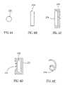
- FIGS. 4A–4Eillustrate several profiles of a rasp, in accordance with exemplary embodiments of the invention.
- FIGS. 5A–5Eillustrate various types of rasping surfaces, in accordance with exemplary embodiments of the invention.
- FIGS. 6A and 6Billustrate details of elbows of the device of FIG. 2 , in accordance with exemplary embodiments of the invention
- FIG. 7illustrates trans-axial navigation of a rasp by pivoting the device of FIG. 2 on the body, in accordance with an exemplary embodiment of the invention
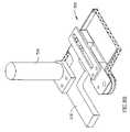
- FIG. 8Ais a side view of a detailed embodiment of a bone removal device, similar to the device of FIG. 2 , in accordance with an exemplary embodiment of the invention.
- FIG. 8Bis an isometric view of the device of FIG. 8A .
- FIG. 2is a schematic side illustration of the deployment of a bone removal device 200 in a spine 130 , in accordance with an exemplary embodiment of the invention.
- Device 200in an exemplary embodiment of the invention, comprises generally of a rasp provider 206 , a rasp take-up 208 coupled to it via a connector 214 and a rasp 202 which passes from the provider 206 , through spine 130 and to take-up 208 .
- device 200includes a handle 210 and at least one control 212 , for example an on/off switch.
- a pair of rasp elbows 204are optionally provided to guide rasp 202 at a proper angle through spinal channel 106 .
- FIG. 1is a schematic side illustration of the deployment of a bone removal device 200 in a spine 130 , in accordance with an exemplary embodiment of the invention.
- Device 200in an exemplary embodiment of the invention, comprises generally of a rasp provider 206 , a rasp take-up 208 coupled to it via a connector 214 and a rasp 202 which passes from
- stenosis 120severed shown
- laminar stenosis 122one shown.
- one or both types of stenosis causing protrusionsare removed, possibly selectively, as described below, thereby increasing the cross-section of the spinal channel.
- rasp 202is guided by elbows 204 so that its cutting surface (see below FIGS. 4A–4E ) is parallel to the portions to be removed. In some cases this may require rotating the rasp around the axis of the spine. In an exemplary embodiment of the invention, such rotation is provided by elbows 204 , for example by the elbows rotating or having two or more channels for guiding the rasp.
- the angle of bend at the elbowis optionally 90°, so that the rasp is parallel to the spine axis. In some cases, it may be desirable to have a different angle, for example between 70° and 90° or between 90° and 110°. Alternatively or additionally, a two step bend may be provided, for example to better match the anatomy.
- Device 200may be employed in many parts of the spine, including the lumbar region and the cervical region.
- FIGS. 3A–3Cschematically illustrate stages in the deployment of device 200 of FIG. 2 , in accordance with an exemplary embodiment of the invention.
- rasp 202is guided through the spinal channel 106 and then the take-up 208 and provider 206 are connected.
- take-up 208 and provider 206are interconnected during the insertion process or pre-connected (or even a single element to begin with) and once rasp 202 is guided through the body it is inserted into take-up 208 .
- FIGS. 3A–3Cillustrate one family of possible methods of guiding rasp 202 through channel 106 , in other embodiments of the invention, other methods may be practiced.
- entry and exit between vertebraeis shown, in some cases entry and/or exit through a vertebra may be desirable. Further, in some cases the entry and exit are at the midline of the spine. However, in others the entry and/or exit may be off the midline, possible on opposite sides of the midline.
- an incision 220is formed between a skin 222 and an entry area 224 into the spinal channel.
- a guide wire or a soft catheter 226is optionally inserted through the incision and into the spinal channel.
- incision 220is formed using an endoscope or a rigid hollow tube, such as a cannula or a needle. In others, a standard surgical incision is formed.
- catheter 226is advanced along-side the spinal cord, inside the spinal channel.
- catheter 226is removed from the spinal channel, for example, as shown using a grasping tool 230 inserted through a second incision 228 .
- a second endoscope(with a grasping tool) is used to remove the catheter.
- the tip of catheter 226is marked to make it easier to locate in the incision 228 .
- markingcan include color, radiant marking such as a blinking LED or an RF transponder, vibration, a unique shape such as a hard sphere, or other means, for example means known in the art for locating objects in a body and especially in a surgical incision.
- an automatic guidance systemmay be used, for example with the catheter tip being magnetic or attracted to a magnet or using a position sensor mounted at the tip of the catheter.
- a styletis inserted into catheter 226 , to aid in pushing it out of the body.
- catheter 226includes a lumen for a retractable sharp tip, which can be extended to cut the tissue ahead of the catheter.
- an extendible eyeor other anchor is provided, for the grasping tool (see below) to grasp. Possible, the leading edge of the anchor is sharp, to perform cutting.
- catheter 226Once catheter 226 exists through incision 228 , it may be pulled to thread an attached rasp 202 through the spinal column.
- the raspmay be pulled forward or backwards so that it leaves the body.
- the raspmay be cut at any point along its length. Possibly a catheter is inserted into the body in order to cut the rasp.
- the cathetermay include an imaging and/or other type of sensor to aid in avoiding damage to the spinal cord while advancing the catheter.
- the cathetermay have non-uniform bend resistance, for example to prevent twisting of the catheter or bending of the catheter out of the plane of the rasp.
- the catheterhas a rectangular profile.
- stiffening spinesor other structural elements are provided along one transaxial dimension of the catheter and not along the other.
- selective weakening of the catheter structureis performed along the other transaxial dimension.
- the motion of rasp 202is one directional.
- the motion of rasp 202is reciprocating.
- the motionis a combination of a slow advance in one direction and reciprocating motion, thus, “used” rasp portions are slowly cycled out of the spine.
- the raspcan remove bone tissue on both the forward and the backwards stroke.
- only one of the strokesremoves bone, for example only the forward stroke or the backward stroke.
- the other (or both) the strokesremove soft tissue, either exclusively or additionally to removing bone.
- This selectivitymaybe achieved, for example by the design of the rasp or by alternating slow and fast motion of the rasp for the different stroke directions.
- the tension in the rasp(for a flexible rasp) is reduced for one of the stroke directions, to reduce the rasping effect of rasp 202 .
- the rasprotates around its axis. If the rasp is twisted or suitably ribbed, this can have the effect of a spiral motion. Alternatively or additionally, a spiral motion is effected by a simultaneous advance and rotation of the rasp.
- the motion of the raspis continuous, except where stopped by the user (or by a safety mechanism).
- pulsed motionis used, one example of pulsed motion is to activate the rasp for a fixed number of cycles, pre activation pulse.
- Another example of pulsed motionis to move the rasp a fixed distance for each activation pulse.
- the spineis bent and/or straightened so that the rasp is in proper contact with the protrusions to be removed.
- One method of bending the spineis to place pillows under a stomach of a patient, possibly using feedback from an X-ray image.
- a set of suitable pillowsmay be provided in a kit from with the rasp.
- inflatable bladdersare used for the pillows.
- the bladdersare single use bladders.
- Another method of bending the spineis to apply traction to the spine, while the patient is in horizontal or vertical orientation. Alternatively or additionally, other methods and devices, such as known in the art, may be used to bend the spine.
- all the stenosis locations along the raspare treated simultaneously.
- only those locations which are not thinned enough by the raspingare rasped again, in series or in parallel. This may require modifying the rasp or moving pillows.
- FIGS. 4A–4Eillustrates several profiles of a rasp, in accordance with exemplary embodiments of the invention.
- FIG. 4Ashows an exemplary, rounded, profile 232 .
- FIG. 4Bshows an exemplary, rectangular, profile 234 .
- Other profilesmay be used as well, for example a convex or a concave arc.
- the profile of FIG. 4Amay be moved axially and/or rotated around its axis for removing bone tissue, depending on the type of device used.
- the profilemay be constant along the rasp.
- the profilemay vary along the rasp.
- the profileremains relatively constant for long stretches of the rasp and then changes, for example, to support a two step rasping procedure—first rough rasping and then fine rasping or first a rasp adapted to remove ligament and then a rasp adapted to remove bone.
- the profilevaries locally, for example alternating fine and rough rasping elements, to achieve a particular effect of the rasp on the bone.
- the profilevaries so as to form grooves in the rasp for the debris of the rasping to travel along. Optionally, such grooves lead the debris into a storage compartment adjacent the rasp or forward, out of the body.
- the profileis optionally symmetric relative to the axis.
- an asymmetrical profilemay be used, for example to better anatomically fit the triangular cross-section of the spinal channel.
- the profilemay vary in that its thickness varies along the length of the rasp.
- the variations in profileare effected by the rasp having ribs or a thread.
- FIG. 4Cillustrates an exemplary embodiment of the invention, in which embodiment a shield 236 is used in conjunction with rasp 234 to prevent the rasp from damaging the spinal cord and/or root nerves.
- the shieldalso serves as a channel for guiding the motion of the rasp.
- the shieldis curved, thus guiding the rasp along a curved path.
- the shieldmay be relatively rigid or it may be flexible like the rasp itself.
- the shieldis formed on the back of the rasp, for example as a smooth surface.
- the shielddoes not move with the rasp. Alternatively, both move, but possibly at different rather than same speed and/or direction.
- the shieldis inserted before the rasp. Alternatively, they are both inserted at the same time. Alternatively, the shield is inserted after the rasp, for example being guided along it. Possibly, a lumen of a catheter or an endoscope is used to guide the shield into the body. Alternatively to being advanced along the channel, the shield (and the rasp, if inserted separately from catheter 226 ) may be retracted along the channel. In some embodiments of the invention, especially where the shield is curved, the shield may be formed of an elastic, super-elastic or shape-memory material, so that it can be inserted in one shape and then it changes to a different shape.
- the shieldserves to collect debris generated by the rasp and prevent the debris from entering the spinal channel. Possibly, the shield encloses the rasp from more than three sides.
- FIG. 4Dshows such a rasp profile, in which a rasp portion 235 is surrounded by a shield 237 from substantially all sides except for a window 231 .
- FIG. 4Eillustrates a rasp profile 233 including a storage compartment for debris, in accordance with an exemplary embodiment of the invention.
- a spiral profileis provided, such that when it is rotated counter-clock wise, portions of tissue removed by the leading edge thereof are forced deeper into the spiral.
- FIGS. 5A–5Eillustrate various types of rasping surfaces, in accordance with exemplary embodiments of the invention.
- Different types of rasping effectscan be produced by selecting different types of rasping surfaces.
- Some examples of rasping effects desirable in some exemplary embodiments of the inventioninclude sanding, crumbling of bone and removing of bone sections by cutting.
- the different rasping effectscan be achieved, for example by selecting a suitable rasp element profile, by controlling the pressure between the rasp and the bone, by controlling the forward speed of the rasp and/or the power profile in general and/or by adding various fluids, such as air or liquid, during the rasping process.
- each elementhas certain structural features, including one or more of an axial, transaxial and top profiles, size, cutting edge and storage for debris. Additionally, various mechanical properties may be set, for example, hardness, sharpness of edge, wear resistance and flexibility. These parameters (and others) may be varied to achieve different types of effects on bone and soft tissue. Additionally, the individual rasp elements may be arranged in different spatial (axial and transaxial) configurations and distributions.
- a rasp section 238has an abrasive surface formed, for example by sandblasting or etching a smooth surface or by attaching a plurality of small protrusions 240 thereto.
- a rasp section 242has a plurality of hollow rasp elements 244 formed therein, for example by punching. As shown by a reference 246 , a side cut-through view of the rasp, the rasp element is cored so that debris caused by the rasping can pass through the rasp.
- rasping elements 244may be formed using other manufacturing methods known in the art including, for example, CNC, casting and cold working.
- the rasp elementsare chemically etched from the rasp, to comprise a tab surrounded on three sides by open space.
- the tab cutting edgeis etched to have a scalloped profile.
- the distance between the front edge of the tab and the rest of the raspmay be used, in some embodiments, to define the size of bone chip removed by the device.
- the generated chipsare used for bone replacement, for example cage surgery for the spine.
- the chipsare removed from a non-vertebral bone.
- the raspmay be adapted to grate the bone, or to remove thin chips, for example, 0.1, 0.5 or even 1 mm.
- the rasp surface, aside from the rasp elementsmay be, for example smooth. In other embodiments, the rasp surface is rough.
- a thin layer having rasping elements formed thereinis attached, for example using spot welding, to a rasp backing layer, to form the final rasp.
- a thin layer having rasping elements formed thereinis attached, for example using spot welding, to a rasp backing layer, to form the final rasp.
- Each of these two layersmay be formed of a different material.
- a rasp section 248has a plurality of rasp elements 250 attached thereto, formed, for example, by soldering. As shown by a reference 52 , a side cut through view, the rasp has different forward and backwards profiles which translate as different amounts resistance to the different motion directions.
- rasping elementsmay be attached to rasp 202 in a variety of ways, including spot welding, gluing, applying pressure or any other method of attaching an element to a surface known in the art.
- the rasping elementsmay be formed of a same or a different material as rasp section 248 .
- a plurality of rasp elements 254are aligned to describe V shapes on a rasp section 253 .
- each of the “V”sis formed of a single tissue removal element.
- a possible advantage of the “V” shapeis that the rasp may be less likely to move sideways while in action.
- a “V” shapea “W” shape or a wave shape may be provided.
- sets of rasps, having different orientationsmay be used.
- rasp elements 256are arranged to be slanting to one side on a rasp 255 .
- a profile of the raspis shown as reference 257 . Transaxial movement of such a rasp may be avoided, for example, by properly shaping individual rasp elements which form the slanting elements or by rigid grasping of the elbows 204 .
- rasp 255may comprise a chain, a cable or a single wire.
- a second wireis spirally mounted on the first wire, to present a rasping surface.
- the raspis a saw with suitably small teeth.
- the various properties of the rasping element, as well as their spatial distribution, relative size and orientationmay vary axially and/or trans-axially along the rasp, for example as explained above with respect to rasp profile.
- the raspis straight.
- the raspis curved, for example trans-axially parallel to the plane of device 200 or trans-axially perpendicular to the plane of device 200 .
- This curvingmay be achieved, for example using a suitably shaped shield 236 .
- the shieldmay be pre-shaped (e.g., shape memory), may be shaped by the insertion process (the elbows) or may be distortable, for example being inflatable or including pull-wires and/or selective weakening so that when force is applied the shield distorts in a desirable manner.
- rasp 202may have a suitable resting condition, for example being a shape memory material, a super elastic material or an elastic material, at least having these properties in the direction of the bend.
- a suitable resting conditionfor example being a shape memory material, a super elastic material or an elastic material, at least having these properties in the direction of the bend.
- a single bendmay be utilized or the rasp can be substantially freeform with any number of bends defined therein.
- the bends in the raspare used to make the rasp conform to a particular inner geometry of the spinal column, for example if the vertebra are not properly aligned, or for conditions of bent backs.
- device 200includes a pathway for inserting an endoscopic viewer into the spinal column to view the location of the rasp and its effect on the bone.
- the endoscopeis inserted while the rasp is inside the body.
- the raspis first removed, possibly leaving a guide wire in the body for easy reinsertion of the rasp, if required.
- device 200includes a pathway or a lumen for providing vacuum and/or positive pressure (e.g., for irrigation) into the spinal column, for example to aid in removing debris caused by the rasping or to aid in separating the various tissues.
- vacuum and/or positive pressuree.g., for irrigation
- FIGS. 6A and 6Billustrate details of elbows 204 ( FIG. 2 ) in accordance with exemplary embodiments of the invention.
- a rotating elbow element 260is shown in which one or more grooves 262 are formed to accommodate rasping elements. These rasping elements are optionally arranged in rows to facilitate their matching such grooves.
- a fixed slip-element 268is shown, across which element rasp 202 slips.
- a side view shown as 264a plurality of grooves 266 are shown to receive rows of rasping elements.
- elbows 204can serve to protect the entry and exit point in the spinal column from undue abrasion.
- lumen 270is shown; such a lumen may be used, for example, for the provision of an endoscopic viewer, a vacuum (for debris removal) or irrigation (for debris removal, cooling and/or friction reduction ) into the spinal channel.
- lumen 270may be at the side of the rasp instead of between the rasp and the bone, as shown.
- the lumenmay be formed in the rasp or in the shield.
- the insertion of device 200may be performed using any one of the known imaging methods, including, CT, MRI, X-ray, fluorography, angiography, ultrasound and vision (optionally using an endoscope).
- two imaging modalitiesmay be combined or different modalities used for different parts of the procedure, for example x-ray for inserting the rasp and an endoscope for monitoring the rasping process.
- ultrasoundis used to estimate the thickness of the bone, at the point where bone is removed.
- Various imaging modescan be used, including regular imaging, calculation of velocity in the bone (which velocity is affected by thickness), attenuation measurement and distance measurement (optionally from a fixed position in the spine).
- the ultrasoundis applied from inside the body, from inside the spinal channel.
- the ultrasoundis applied from outside the body.
- an ultrasound transducer used for measurementis integral with the protector or the rasp.
- FIG. 7illustrates trans-axial navigation of rasp 202 by pivoting device 200 around incisions 220 and 228 .
- the body tissueserves as a pivot which causes the rasp to move to the other side of the spinal midline.
- This pivotingis provided by a suitably shaped elbow 204 .
- the elbowis fixed relative to the spine, however it supports sliding of rasp 202 in a trans-axial direction or rotates axially (around the spine axis), so that rasp 202 moves in a trans-axial direction.
- elbows 204being fixed relative to the spine is that it confers stability on the location of the rasp in the body, in spite of the considerable and varying pressures exerted on the rasp in various directions.
- the type and size of the particles of the debrisdepend on the type of rasp elements and the power profile of the rasping activity.
- the type, age and disease state of the tissuemay also affect the particle sizes.
- the debrisis collected in rasp 202 itself, for example in the hollows of the rasping elements themselves or in a container formed inside rasp 202 .
- the amount or required collections pacedepends, inter alia, on the number of times a single element will come in contact with bone and on the amount of bone it removes each time.
- the debrisis collected between the rasp and the shield layer or in a container formed in the shield layer.
- the collected debrismay be removed by the forward movement of the rasp, as it advances out of the body.
- the debrismay be removed by the rasp effecting a spiral motion which pumps the debris out of the body (possibly even uncollected debris).
- the debrismay be flushed out or sucked out by suitable providing positive or negative pressure at the entry and exit holes or along the rasp.
- the containeris periodically removed for cleaning.
- a desired pressure between the rasp surface and the bone to be removedis another issue to be considered.
- a constant pressureis maintained by fixing device 200 to the spine and providing a spring between the device and the rasp, to control the pressure.
- ligament 110is removed instead of or in addition to bone.
- the selective removal of one tissue typemay be affected in some exemplary embodiments of the invention, for example, by suitably selecting the rasping elements, the rasp profile, rasp placement, rasp-tissue pressure, rasp speed and/or power application profile,
- the ligamentis removed first, before reaching the bone.
- the raspmay be inserted between the ligament and the bone, to selectively remove the bone without removing the ligament or removing only the bone-facing portion thereof and not the spinal cord facing portion thereof.
- Another issue to be considered in some exemplary embodiments of the inventionis the provision of feedback of the rasping process, to assess its progress and/or to prevent damage to sensitive tissues.
- a basic form of feedbackuses one of the imaging modalities mentioned above, or any other modality, to directly image the desired parameter, e.g., the rasp location, amount of bone removed, damage to the spinal cord, etc.
- a mechanical measurement methodsuch as a caliper, may be used.
- the thickness of tissue removedis estimated base on parameters of the rasping, for example, the length of time for which the rasp was activated, the pressure applied between the rasp and the tissue, the length the rasp has advanced, the tissue type and/or the amount of tissue removed.
- a trans axial motion of the raspcan be measured, using the device of FIG. 8A (e.g., spring 334 ).
- a color based methodcan be used.
- noteis made of the color of removed tissue, and based on the ratio between bone and ligament in the removed tissue, of the thickness of tissue removed, is estimated.
- the amount of blood flowis used to estimate the type of tissue being removed.
- the tissue to be removedis stained, over its surface and possibly to a desired depth and note is made of the color of removed tissue.
- the tissuemay be stained, for example, by a first length part of the rasp or by an endoscope or catheter 226 used for this purpose.
- a monitoring of the color of remaining tissuemay be used, for example using an endoscope or possibly even using a frequency selective photo-sensor mounted inside the body, for example, on one of the elbows or on the shield.
- the stenosis causing artifactsare often localized.
- a change in the resistance characteristics of the tissuecan be expected and/or monitored for. It is expected that bone, ligaments and blood vessel tissue all exhibit different type of resistance profiles to motion of a rasp. In any case, if the rasp engages more than a certain percentage of the spinal column a safety hazard can be decided and the operation stopped automatically.
- the displacement of the raspwill change significantly.
- the amount of displacement or the rate of change of displacementmay also be used to estimate the thickness of tissue removed.
- the amount of tension in the raspis monitored.
- a break in the raspis determined, and the power stopped.
- a determination that the rasp is stuckmay be made.
- the operationis stopped periodically so that a doctor can obtain tactile or audio feedback, for example by moving the rasp manually.
- the rasp elementsare degraded as they are used, once a certain part of the rasp has removed a certain amount of bone, all the rasp elements at that part are smoothed and that rasp portion does not cause any more tissue removal.
- the raspmay include a portion which is degraded as the rasp is used, and the thickness and/or opacity of that portion examined to assess the amount of tissue removed.
- safety mechanismsare provided to avoid nerve damage.
- measurements of evoked potentialare carried out on the branching nerves, to determine changes in pressure caused by the spinal stenosis.
- conduction velocity in the nervesmay be measured to monitor the reduction in stenosis and/or damage caused by the treatment.
- the raspprior to measurement the rasp is rotated around the axis of the spine to a location where there is more room, so that the rasp itself does not exert pressure on the spine.
- the raspincludes a pressure sensor at its back and/or the back of the shield, so that the contact pressure between the rasp an the spinal cord can be monitored.
- FIG. 8Ais a side view of a detailed embodiment of bone removal device 300 , similar to device 200 , in accordance with an exemplary embodiment of the invention.
- FIG. 8Bis an isometric view of device 300 , omitting some elements.
- Device 300comprises a rasp providing unit 306 which provides a rasp 302 from a rasp reel 322 , along an inserting extension 318 to a first elbow 304 and then to a removal elbow 304 ′, along a removal extension 320 and to a rasp uptake reel 324 which forms part of a rasp take up unit 308 .
- Providing unit 306 and take-up unit 308are optionally interconnected using connector 314 , which can control the distance between the take-up and the providing units. This distance can be used to directly control the length of spinal column treated or, if extensions 318 and/or 320 can be angled, as in some exemplary embodiments of the invention, to indirectly control this length.
- a handle 310 and possibly a perpendicular handle 326are provided to allow a physician to hold the device in a stable manner.
- device 300may be fixed relative to the patient and/or a patient bed.
- a bone rest 330is provided, so that device 300 can rest directly against the bone.
- a back restis provided so the device rests against the skin of the back of the patient.
- bone rest 330expands radially, so that it can be easily inserted into a narrow incision.
- other solutionsmay be provided, for example the bone rest may fold or a larger incision used.
- bone rest 330includes retractable spikes (not shown) for engaging the vertebra).
- bone rest 330matches the anatomy of the vertebra to assist in achieving a stable resting configuration.
- elbows 304are attached to device 300 using a spring 334 , which controls the pressure exerted by rasp 302 against the spinal column.
- a screw or other element 336is provided for controlling the tension in the spring.
- a sensor 332is provided to determine proper contact between bone rest 330 and the spine.
- device 300is inactivated if a low and/or high contact pressure is detected.
- a sensor 338is provided to measure the tension in the spiring and/or to measure displacement of elbow 304 relative to bone rest 330 .
- two such bone restsare used, even though only one is shown. In other embodiments, only one bone rest is used.
- catheter 226is threaded on take-up reel 324 after it passes through the spinal channel.
- rasp 302is directly threaded on the take up reel.
- rasp 302is 5 meters long, 4 millimeters wide and between 0.05 and 0.15 millimeters thick.
- the motionis reciprocating at an amplitude of 2 millimeters and a frequency of 1 Hz and the rasp advances at a speed of 1 meter a minute.
- the AC motion magnitudeis significantly greater than that of the DC motion. In other embodiments, the magnitudes may be similar or the DC motion may be smaller.
- the rasp materialis metallic, for example stainless steel.
- at least the rasp elementsare formed of plastic.
- plasticis that it can be made bio-absorbable so that any pieces which chip off are rapidly absorbed and do not cause mechanical damage or promote infection.
- the raspis formed of a cloth material, possibly with abrasive material glued on.
- clothis an increased resistance to tearing and/or other types of mechanical failure.
- parts of device 300are made for a single use and/or for a single patient.
- the entire deviceis a one-time device.
- rasp 302is one time and is provided, for example packaged with a providing reel 322 or with an entire providing unit 306 .
- all the portions which come in contact with body fluidsare disposable and/or separable and sterilizable, possibly being provided as a cartridge which encompasses the rasp, the extensions, the elbows and optionally the reels.
- a first type of selectivityis selecting which tissue type to removed, for example only bone or only ligament.
- This selectivitymay be achieved, for example by suitable controlling of the rasp structural and/or movement parameters.
- Another method of achieving this selectivityis to provide a rasp having two parts, a ligament removal length and a bone removal length and to selectively use the desired part (or separate devices). Possibly, two or more rasp types may be threaded simultaneously through the spinal channel and only one used at a time.
- the raspis two sided, with each side having a different effect on tissue.
- a local axial variation methodmay be used, in which method nearby portions of the rasp have different tissue effects.
- the raspis rotated, only those portions which have a bone removing effect will remove bone while nearby portions will not.
- a raspis axially advanced. The amplitude of reciprocating motion is kept small and once that part of the rasp is done rasping, the rasp is advanced a great amount, so that it does not removed undesired bone.
- the raspis neutral with regard to tissue abrasion and a tissue affecting element is advanced along the rasp to a desired abrasion location.
- portions of the raspmay be prevented from performing their abrasive function, for example by sliding one or more shield segments over the rasp so that only at desired windows is the rasp in contact with body tissue.
- these shield segmentsmay affect the distance between the rasp and the body tissue, the tension, the pressure and/or rotate the rasp.
- the shieldprovides the tension in the rasp, for example by applying transaxial pressure against the rasp.
- rasp motion parameterssuch as stroke length, tension, frequency, etc.
- various rasping effectscan be achieved.
- an image guided procedureis used in which the position of the rasp relative to the tissue to be removed is shown.
- the imageis optionally coupled to the rasp device, possibly simplifying coordinate registration problems however, this is not required.
- the raspoptionally includes markers which enable the axial position of the rasp to be determined from the image, however, this is not required.
- the position of the raspis determined using an optical encoder or a different type of encoder on the rasp or on one or both of the reels.
- the rasp position determinationis utilized by a controller to match desired variations in rasp structure and/or rasp movement to a particular situation.
- a controllerto match desired variations in rasp structure and/or rasp movement to a particular situation.
- an image or scheme of the spineshowing what is to be removed in first entered into the computer, to plan the procedure, however, this may also be done in real time.
- manual “fast forward”, “reverse” and “activate” buttonsmay be provided, as well as controls to vary selected ones of the myriad of available parameters.
- the rasping processitself may proceed as a single extended step in which a single type of activity is performed until the desired rasping effect is achieved.
- a multi-step processmay be used, for example first rough rasping and then fine rasping or rasping one vertebra at a time (even though all the vertebra are threaded by the rasp) or first removing ligament and then removing bone.
- the availability of the rasp threaded in the bodymay be used to treat the rasped area, for example using radioactivity or heat (to prevent re-growth) or by applying pharmaceuticals, such as healing promoters.
- These materialsmay be attached to the rasp itself or may be guided along or over the rasp and/or the shield, for example using one or more catheters or endoscopes.
- the raspis cooled (inside the body) or pre-cooled (prior to being inserted into the body.
- This coolingcan be used to counteract the friction heating of the rasp.
- the coolingcan be used to affect the tissue structure and assist in tissue removal and/or in the selectivity of tissue removal.
- the coolingmay be towards the bone or towards the nerve.
- the raspinclude a material with a high thermal coefficient, so that the cooling effect is maintained.
- the rasp or the shieldinclude insulation, to block the heat from reaching the spinal cord.
- heatingmay be applied, for example to counteract excessive cooling.
- the motion of the raspis made responsive to its temperature, which may be measured in the body or after it leaves the body.
- a cooling liquidis provided in the spine. The temperature of this liquid may be monitored to prevent adverse effects of heating.
- a support mesh or another type of membraneis provided over the rasped area, for example to promote healing or to prevent adhesion.
- the power for moving the raspis provided at the take-up reel.
- the poweris electric, pneumatic or hydraulic.
- the poweris manual, being apply by a physician, for example, either by turning the reel or by advancing the entire device 300 .
- powermay be provided at least partly locally, for example by providing piezoelectric materials on the rasp, which when activated, cause the rasp elements to move.
- vibration of the raspmay be affected by providing a rasp with a high Q factor, for efficient transmission of ultrasonic vibrations along the rasp, from outside the body.
- the power trainincludes various safety featured.
- a clutchis provided which only releases the rasp to move if a minimum amount of rasp-bone pressure is applied or if a minimum amount of tension is achieved in the rasp.
- a maximum power cut-offthat stops the rasp motion if the required power is above a pre-selected limit or a calculated limit.
- portions of the spinemay be removed for other reasons.
- One possible applicationis removing portions of the spine to aid in straightening a bent back. By allowing controlled removal of bone without major surgical incisions, less aggressive treatments than practiced today may become more prevalent.
- portions of the bone on the outside of the spinemay also be removed and/or grooves formed therein, for example to assist in bending of the spine.
- a similar devicemay be used for removing bone portions from outside the spine.
- the rasp(and/or a shield thereof) can be twisted 90° or 180° around its axis so that it points away from the device.
- Such a modified devicecan still be used without a major incision.
- such a devicemay be used for forming groves (straight or curved ) in other bones, such as a femur.
- a two step processmay be used. In a first step a deep narrow grove is formed and the rasp inserted therein. In a second step, the rasp is rotated or expanded (or a wider rasp provided) so that a wider diameter groove is formed at the base of the narrow groove.
- minimally invasive removal of bonemay be practiced.
- bent bonese.g., a femur
- bone platesfor applying bone plates to broken bones, with a better conformity to the bone geometry (possibly along the path of the rasp) and/or for corrective surgery of deformed complex joints, such as wrists and ankles, where a plurality of bones need to be reshaped to match against each other.
- the raspis deployed inside an intra-medullar space of a bone with the rasp pointed in the direction of the device, to the side or even away from it.
- a portion of vertebral bonemay be removed with a minimal compromising of the surface of the vertebrae, inside the spinal channel and/or outside of it.
- a boremay be drilled in the vertebra, from between two vertebrae along a path which does not intersect with the surface of the vertebra. The removal of the bone softens the vertebra, so that inflating a device inside the spinal channel and/or otherwise applying pressure against the vertebra from inside will increase the radius of the spinal channel.
- the inside of the boreis hooked and retracted, to cause it to collapse, Thus, there may be less danger of inflammation adjacent the spinal column.
- the tool used for boringcomprises a drill and/or a rasp.
- an entry-exit devicehas been described.
- a single hole deviceis used, which is inserted into the spine as in FIGS. 3A and 3B and then activated, without requiring the rasp to exit the body as in FIG. 3C .
- an extension 318can be extended into the spinal channel and the rasp run along it.
- One type of suitable raspis a self-engaging rasp, in which the rasp elements, once in contact with the bone, engage the bone to a greater extent, reducing the need to apply external pressure to maintain proper contact between the rasp and the bone.
- higher motion frequenciesmay be used.
- One suitable type of rasp motionis reciprocating.
- the raspis arranged like a conveyor belt, so that used parts of the rasp exit along the same path that they used to enter the body, optionally separated from the spinal cord by a shield layer.
- rotational motion of the raspmay be used for removing bone.
- Such a one-sided devicemay be especially useful for treating stenosis of the branching nerve channels.
- a rigid shieldis provided to protect the branching nerve.
- the shieldhas a form adapted to the anatomy of the channel.
- the raspis optionally a rotational rasping device.
Landscapes
- Health & Medical Sciences (AREA)
- Surgery (AREA)
- Life Sciences & Earth Sciences (AREA)
- Medical Informatics (AREA)
- Animal Behavior & Ethology (AREA)
- Engineering & Computer Science (AREA)
- Biomedical Technology (AREA)
- Heart & Thoracic Surgery (AREA)
- Veterinary Medicine (AREA)
- Molecular Biology (AREA)
- Nuclear Medicine, Radiotherapy & Molecular Imaging (AREA)
- General Health & Medical Sciences (AREA)
- Public Health (AREA)
- Orthopedic Medicine & Surgery (AREA)
- Dentistry (AREA)
- Oral & Maxillofacial Surgery (AREA)
- Surgical Instruments (AREA)
Abstract
Description
Claims (52)
Applications Claiming Priority (2)
| Application Number | Priority Date | Filing Date | Title |
|---|---|---|---|
| IL131197AIL131197A (en) | 1999-08-01 | 1999-08-01 | Apparatus for spinal procedures |
| PCT/IL2000/000458WO2001008571A1 (en) | 1999-08-01 | 2000-08-01 | Method and apparatus for spinal procedures |
Publications (1)
| Publication Number | Publication Date |
|---|---|
| US7189240B1true US7189240B1 (en) | 2007-03-13 |
Family
ID=11073093
Family Applications (1)
| Application Number | Title | Priority Date | Filing Date |
|---|---|---|---|
| US10/031,450Expired - Fee RelatedUS7189240B1 (en) | 1999-08-01 | 2000-08-01 | Method and apparatus for spinal procedures |
Country Status (4)
| Country | Link |
|---|---|
| US (1) | US7189240B1 (en) |
| AU (1) | AU6312700A (en) |
| IL (1) | IL131197A (en) |
| WO (1) | WO2001008571A1 (en) |
Cited By (77)
| Publication number | Priority date | Publication date | Assignee | Title |
|---|---|---|---|---|
| US20050070915A1 (en)* | 2003-09-26 | 2005-03-31 | Depuy Spine, Inc. | Device for delivering viscous material |
| US20060036272A1 (en)* | 2004-07-29 | 2006-02-16 | X-Sten, Inc. | Spinal ligament modification |
| US20060089609A1 (en)* | 2004-10-15 | 2006-04-27 | Baxano, Inc. | Devices and methods for tissue modification |
| US20060095059A1 (en)* | 2004-10-15 | 2006-05-04 | Baxano, Inc. | Devices and methods for tissue modification |
| US20060161189A1 (en)* | 2002-09-27 | 2006-07-20 | Harp Richard J | Surgical file system with a visualization instrument |
| US20060241648A1 (en)* | 2005-02-04 | 2006-10-26 | Bleich Jeffery L | Methods and apparatus for tissue modification |
| US20070027464A1 (en)* | 2005-07-29 | 2007-02-01 | X-Sten, Corp. | Device for resecting spinal tissue |
| US20070123888A1 (en)* | 2004-10-15 | 2007-05-31 | Baxano, Inc. | Flexible tissue rasp |
| US20070213734A1 (en)* | 2006-03-13 | 2007-09-13 | Bleich Jeffery L | Tissue modification barrier devices and methods |
| US20070213733A1 (en)* | 2004-10-15 | 2007-09-13 | Bleich Jeffery L | Mechanical tissue modification devices and methods |
| US20070225703A1 (en)* | 2005-10-15 | 2007-09-27 | Baxano, Inc. | Flexible Tissue Removal Devices and Methods |
| US20070270865A1 (en)* | 2006-04-05 | 2007-11-22 | Uri Arnin | Spinal reamer |
| US20070276390A1 (en)* | 2006-05-09 | 2007-11-29 | X-Sten, Inc. | Ipsilateral Approach to Minimally Invasive Ligament Decompression Procedure |
| US20080086114A1 (en)* | 2006-08-29 | 2008-04-10 | Baxano, Inc. | Tissue Access Guidewire System and Method |
| US20080103504A1 (en)* | 2006-10-30 | 2008-05-01 | Schmitz Gregory P | Percutaneous spinal stenosis treatment |
| US20080221383A1 (en)* | 2007-02-12 | 2008-09-11 | Vertos Medical, Inc. | Tissue excision devices and methods |
| US20090069709A1 (en)* | 2007-09-06 | 2009-03-12 | Baxano, Inc. | Method, system, and apparatus for neural localization |
| US20090107511A1 (en)* | 2006-05-11 | 2009-04-30 | Yossi Gross | Implantable respiration therapy device |
| US20090118709A1 (en)* | 2007-11-06 | 2009-05-07 | Vertos Medical, Inc. A Delaware Corporation | Tissue Excision Tool, Kits and Methods of Using the Same |
| US7578819B2 (en) | 2005-05-16 | 2009-08-25 | Baxano, Inc. | Spinal access and neural localization |
| US20100094298A1 (en)* | 2008-10-14 | 2010-04-15 | Neville Alleyne | Rearchitecting the spine |
| US7738969B2 (en) | 2004-10-15 | 2010-06-15 | Baxano, Inc. | Devices and methods for selective surgical removal of tissue |
| US20110060314A1 (en)* | 2004-10-15 | 2011-03-10 | Wallace Michael P | Devices and methods for treating tissue |
| US20110087255A1 (en)* | 2009-08-07 | 2011-04-14 | Mccormack Bruce M | Systems and methods for treatment of compressed nerves |
| US7938830B2 (en)* | 2004-10-15 | 2011-05-10 | Baxano, Inc. | Powered tissue modification devices and methods |
| US20110112539A1 (en)* | 2008-07-14 | 2011-05-12 | Wallace Michael P | Tissue modification devices |
| US7985254B2 (en) | 2007-01-08 | 2011-07-26 | David Tolkowsky | Endobronchial fluid exhaler devices and methods for use thereof |
| US20110190772A1 (en)* | 2004-10-15 | 2011-08-04 | Vahid Saadat | Powered tissue modification devices and methods |
| US8062300B2 (en)* | 2006-05-04 | 2011-11-22 | Baxano, Inc. | Tissue removal with at least partially flexible devices |
| US20110307061A1 (en)* | 2010-06-15 | 2011-12-15 | Zyga Technology, Inc. | Systems and methods for facet joint treatment |
| US8080011B2 (en) | 2002-09-27 | 2011-12-20 | Surgitech, L.L.C. | Reciprocating cutting tool |
| US8092456B2 (en) | 2005-10-15 | 2012-01-10 | Baxano, Inc. | Multiple pathways for spinal nerve root decompression from a single access point |
| WO2012004766A2 (en) | 2010-07-07 | 2012-01-12 | Yoseph Weitzman | Surgical device for tissue removal |
| US20120065639A1 (en)* | 2007-12-07 | 2012-03-15 | Schmitz Gregory P | Tissue modification devices |
| US8221397B2 (en) | 2004-10-15 | 2012-07-17 | Baxano, Inc. | Devices and methods for tissue modification |
| US8257356B2 (en)* | 2004-10-15 | 2012-09-04 | Baxano, Inc. | Guidewire exchange systems to treat spinal stenosis |
| USD666725S1 (en) | 2010-09-15 | 2012-09-04 | Thayer Intellectual Property, Inc. | Handle for a medical device |
| US8287538B2 (en) | 2008-01-14 | 2012-10-16 | Conventus Orthopaedics, Inc. | Apparatus and methods for fracture repair |
| USD673683S1 (en) | 2010-09-15 | 2013-01-01 | Thayer Intellectual Property, Inc. | Medical device |
| USD674489S1 (en) | 2010-09-15 | 2013-01-15 | Thayer Intellectual Property, Inc. | Handle for a medical device |
| US8366712B2 (en) | 2005-10-15 | 2013-02-05 | Baxano, Inc. | Multiple pathways for spinal nerve root decompression from a single access point |
| US20130053851A1 (en)* | 2004-10-15 | 2013-02-28 | Gregory P. Schmitz | Access and tissue modification systems and methods |
| US8394102B2 (en) | 2009-06-25 | 2013-03-12 | Baxano, Inc. | Surgical tools for treatment of spinal stenosis |
| US8398641B2 (en) | 2008-07-01 | 2013-03-19 | Baxano, Inc. | Tissue modification devices and methods |
| US8409206B2 (en) | 2008-07-01 | 2013-04-02 | Baxano, Inc. | Tissue modification devices and methods |
| US20130165962A1 (en)* | 2010-05-04 | 2013-06-27 | Brian S. Porshinsky | Surgical device, method of performing surgery using same, and surgical device kit |
| US8613745B2 (en) | 2004-10-15 | 2013-12-24 | Baxano Surgical, Inc. | Methods, systems and devices for carpal tunnel release |
| US8652157B2 (en) | 2009-08-07 | 2014-02-18 | Thayer Intellectual Property, Inc. | Systems and methods for treatment of compressed nerves |
| WO2014041540A1 (en) | 2012-09-11 | 2014-03-20 | Carevature Medical Ltd. | Tissue removal device |
| US8696707B2 (en) | 2005-03-08 | 2014-04-15 | Zyga Technology, Inc. | Facet joint stabilization |
| US8753364B2 (en) | 2009-08-07 | 2014-06-17 | Thayer Intellectual Property, Inc. | Systems and methods for treatment of compressed nerves |
| US20140222004A1 (en)* | 2012-05-29 | 2014-08-07 | Tokyo Wire Works, Ltd. | Wire Saw |
| US8801626B2 (en) | 2004-10-15 | 2014-08-12 | Baxano Surgical, Inc. | Flexible neural localization devices and methods |
| US8906022B2 (en) | 2010-03-08 | 2014-12-09 | Conventus Orthopaedics, Inc. | Apparatus and methods for securing a bone implant |
| EP2823777A1 (en)* | 2013-07-12 | 2015-01-14 | Peter Marks | Surgical processing tool for bone surgery |
| US8961518B2 (en) | 2010-01-20 | 2015-02-24 | Conventus Orthopaedics, Inc. | Apparatus and methods for bone access and cavity preparation |
| US9233006B2 (en) | 2010-06-15 | 2016-01-12 | Zyga Technology, Inc. | Systems and methods for facet joint treatment |
| US20160008043A1 (en)* | 2004-10-26 | 2016-01-14 | P Tech, Llc | Tissue fixation system and method |
| US9247952B2 (en) | 2004-10-15 | 2016-02-02 | Amendia, Inc. | Devices and methods for tissue access |
| US9314253B2 (en) | 2008-07-01 | 2016-04-19 | Amendia, Inc. | Tissue modification devices and methods |
| EP3173036A1 (en)* | 2015-11-27 | 2017-05-31 | NES-Med GmbH | Device for removing bone or connective tissue, in particular for decompressing the vertebral canal in spinal stenosis |
| US9730739B2 (en) | 2010-01-15 | 2017-08-15 | Conventus Orthopaedics, Inc. | Rotary-rigid orthopaedic rod |
| US9833328B2 (en) | 2010-06-15 | 2017-12-05 | Zyga Technology | System and methods for facet joint treatment |
| US10022132B2 (en) | 2013-12-12 | 2018-07-17 | Conventus Orthopaedics, Inc. | Tissue displacement tools and methods |
| US20190142438A1 (en)* | 2016-04-22 | 2019-05-16 | Skajster Familienstiftung | Surgical milling cutter |
| US20190167277A1 (en)* | 2016-08-10 | 2019-06-06 | Inje University Industry-Academic Cooperation Foundation | Semicylindrical osteotomy device |
| US10548619B2 (en) | 2011-04-29 | 2020-02-04 | Michael P. Wallace | Selective spinal tissue removal apparatus and method |
| US10869689B2 (en) | 2017-05-03 | 2020-12-22 | Medtronic Vascular, Inc. | Tissue-removing catheter |
| US10918426B2 (en) | 2017-07-04 | 2021-02-16 | Conventus Orthopaedics, Inc. | Apparatus and methods for treatment of a bone |
| US11219498B2 (en)* | 2014-10-28 | 2022-01-11 | Spinal Elements, Inc. | Tissue protector and method of use |
| US11357534B2 (en) | 2018-11-16 | 2022-06-14 | Medtronic Vascular, Inc. | Catheter |
| US11596419B2 (en) | 2017-03-09 | 2023-03-07 | Flower Orthopedics Corporation | Plating depth gauge and countersink instrument |
| US11690645B2 (en) | 2017-05-03 | 2023-07-04 | Medtronic Vascular, Inc. | Tissue-removing catheter |
| US11707292B2 (en) | 2021-02-01 | 2023-07-25 | Mazor Robotics Ltd. | Disc cleaning surgical tool |
| US11819236B2 (en) | 2019-05-17 | 2023-11-21 | Medtronic Vascular, Inc. | Tissue-removing catheter |
| US12102348B2 (en) | 2016-09-07 | 2024-10-01 | Vertos Medical, Inc. | Percutaneous lateral recess resection methods and instruments |
| US12324572B2 (en) | 2022-06-16 | 2025-06-10 | Vertos Medical, Inc. | Integrated instrument assembly |
Families Citing this family (24)
| Publication number | Priority date | Publication date | Assignee | Title |
|---|---|---|---|---|
| US7621950B1 (en) | 1999-01-27 | 2009-11-24 | Kyphon Sarl | Expandable intervertebral spacer |
| JP2003116868A (en)* | 2001-10-19 | 2003-04-22 | Yamashita Hiroyuki | Surgical ribbon file |
| US6932821B2 (en) | 2002-09-28 | 2005-08-23 | Precimed S.A. | Femoral broach with undercut teeth |
| ES2545328T3 (en) | 2003-03-14 | 2015-09-10 | Depuy Spine, Inc. | Bone cement hydraulic injection device in percutaneous vertebroplasty |
| US8066713B2 (en) | 2003-03-31 | 2011-11-29 | Depuy Spine, Inc. | Remotely-activated vertebroplasty injection device |
| ATE363864T1 (en)* | 2003-04-11 | 2007-06-15 | Martin Nolde | RASP ATTACHMENT FOR A MOTOR-DRIVEN HAND-HELD SURGICAL DEVICE |
| US8415407B2 (en) | 2004-03-21 | 2013-04-09 | Depuy Spine, Inc. | Methods, materials, and apparatus for treating bone and other tissue |
| CN101065080B (en) | 2004-07-30 | 2021-10-29 | 德普伊新特斯产品有限责任公司 | Materials and Instruments for Manipulating Bone and Other Tissues |
| US9381024B2 (en) | 2005-07-31 | 2016-07-05 | DePuy Synthes Products, Inc. | Marked tools |
| US9918767B2 (en) | 2005-08-01 | 2018-03-20 | DePuy Synthes Products, Inc. | Temperature control system |
| US8998923B2 (en) | 2005-08-31 | 2015-04-07 | Spinealign Medical, Inc. | Threaded bone filling material plunger |
| US8360629B2 (en) | 2005-11-22 | 2013-01-29 | Depuy Spine, Inc. | Mixing apparatus having central and planetary mixing elements |
| US7699894B2 (en) | 2005-12-22 | 2010-04-20 | Depuy Spine, Inc. | Nucleus pulposus trial device and technique |
| CA2646251A1 (en)* | 2006-03-13 | 2007-09-20 | Baxano, Inc. | Methods and apparatus for tissue modification |
| AU2012201909B2 (en)* | 2006-03-13 | 2013-01-17 | Baxano, Inc | Methods and apparatus for tissue modification |
| AU2007297097A1 (en) | 2006-09-14 | 2008-03-20 | Depuy Spine, Inc. | Bone cement and methods of use thereof |
| US8950929B2 (en) | 2006-10-19 | 2015-02-10 | DePuy Synthes Products, LLC | Fluid delivery system |
| EP2241274B1 (en)* | 2006-12-07 | 2012-02-01 | Baxano, Inc. | Tissue removal devices |
| US20080255624A1 (en)* | 2007-03-30 | 2008-10-16 | Gregory Arcenio | Methods and devices for multipoint access of a body part |
| USD610259S1 (en) | 2008-10-23 | 2010-02-16 | Vertos Medical, Inc. | Tissue modification device |
| USD619252S1 (en) | 2008-10-23 | 2010-07-06 | Vertos Medical, Inc. | Tissue modification device |
| USD619253S1 (en) | 2008-10-23 | 2010-07-06 | Vertos Medical, Inc. | Tissue modification device |
| USD635671S1 (en) | 2008-10-23 | 2011-04-05 | Vertos Medical, Inc. | Tissue modification device |
| USD611146S1 (en) | 2008-10-23 | 2010-03-02 | Vertos Medical, Inc. | Tissue modification device |
Citations (14)
| Publication number | Priority date | Publication date | Assignee | Title |
|---|---|---|---|---|
| US2355124A (en)* | 1941-12-23 | 1944-08-08 | Curt B Muller | Endless-band tool |
| US2372553A (en)* | 1942-06-11 | 1945-03-27 | Continental Machines | File band |
| US3523348A (en)* | 1968-04-09 | 1970-08-11 | C O Oberg & Co S Ab | Holder for machine tools of flexible material having teeth or a cutting edge |
| DE3209403A1 (en) | 1982-03-16 | 1983-09-22 | M.A.N. Maschinenfabrik Augsburg-Nürnberg AG, 8000 München | Device for making an excavation in a bone |
| DE4036804A1 (en) | 1990-11-19 | 1992-05-21 | Univ Halle Wittenberg | Instruments for decompression of cervical narrow spinal channel - act to remove dorsal edge points of vertebrae and ventral bridge building of damaged segments |
| WO1997009940A1 (en) | 1995-09-12 | 1997-03-20 | C G Surgical Limited | A device to stabilise the lamina |
| US5628678A (en) | 1996-05-03 | 1997-05-13 | Tridico; Frank | Shaft sanding device |
| US5713785A (en)* | 1997-01-17 | 1998-02-03 | Linax Co., Ltd. | Vacuum type portable sander |
| US5722977A (en) | 1996-01-24 | 1998-03-03 | Danek Medical, Inc. | Method and means for anterior lumbar exact cut with quadrilateral osteotome and precision guide/spacer |
| US5725530A (en) | 1996-06-19 | 1998-03-10 | Popken; John A. | Surgical saw and methods therefor |
| WO1998029047A1 (en) | 1997-01-02 | 1998-07-09 | Saint Francis Medical Technologies, Llc | Spine distraction implant and method |
| US5792044A (en) | 1996-03-22 | 1998-08-11 | Danek Medical, Inc. | Devices and methods for percutaneous surgery |
| US5879353A (en) | 1995-01-17 | 1999-03-09 | Gore Enterprise Holdings, Inc. | Guided bone rasp |
| US6068542A (en)* | 1996-07-24 | 2000-05-30 | Tomoe Engineering Co, Ltd. | Pad tape surface polishing method and apparatus |
- 1999
- 1999-08-01ILIL131197Apatent/IL131197A/ennot_activeIP Right Cessation
- 2000
- 2000-08-01AUAU63127/00Apatent/AU6312700A/ennot_activeAbandoned
- 2000-08-01USUS10/031,450patent/US7189240B1/ennot_activeExpired - Fee Related
- 2000-08-01WOPCT/IL2000/000458patent/WO2001008571A1/enactiveApplication Filing
Patent Citations (14)
| Publication number | Priority date | Publication date | Assignee | Title |
|---|---|---|---|---|
| US2355124A (en)* | 1941-12-23 | 1944-08-08 | Curt B Muller | Endless-band tool |
| US2372553A (en)* | 1942-06-11 | 1945-03-27 | Continental Machines | File band |
| US3523348A (en)* | 1968-04-09 | 1970-08-11 | C O Oberg & Co S Ab | Holder for machine tools of flexible material having teeth or a cutting edge |
| DE3209403A1 (en) | 1982-03-16 | 1983-09-22 | M.A.N. Maschinenfabrik Augsburg-Nürnberg AG, 8000 München | Device for making an excavation in a bone |
| DE4036804A1 (en) | 1990-11-19 | 1992-05-21 | Univ Halle Wittenberg | Instruments for decompression of cervical narrow spinal channel - act to remove dorsal edge points of vertebrae and ventral bridge building of damaged segments |
| US5879353A (en) | 1995-01-17 | 1999-03-09 | Gore Enterprise Holdings, Inc. | Guided bone rasp |
| WO1997009940A1 (en) | 1995-09-12 | 1997-03-20 | C G Surgical Limited | A device to stabilise the lamina |
| US5722977A (en) | 1996-01-24 | 1998-03-03 | Danek Medical, Inc. | Method and means for anterior lumbar exact cut with quadrilateral osteotome and precision guide/spacer |
| US5792044A (en) | 1996-03-22 | 1998-08-11 | Danek Medical, Inc. | Devices and methods for percutaneous surgery |
| US5628678A (en) | 1996-05-03 | 1997-05-13 | Tridico; Frank | Shaft sanding device |
| US5725530A (en) | 1996-06-19 | 1998-03-10 | Popken; John A. | Surgical saw and methods therefor |
| US6068542A (en)* | 1996-07-24 | 2000-05-30 | Tomoe Engineering Co, Ltd. | Pad tape surface polishing method and apparatus |
| WO1998029047A1 (en) | 1997-01-02 | 1998-07-09 | Saint Francis Medical Technologies, Llc | Spine distraction implant and method |
| US5713785A (en)* | 1997-01-17 | 1998-02-03 | Linax Co., Ltd. | Vacuum type portable sander |
Cited By (181)
| Publication number | Priority date | Publication date | Assignee | Title |
|---|---|---|---|---|
| US20060200153A1 (en)* | 2002-09-27 | 2006-09-07 | Harp Richard J | Surgical assembly for tissue removal |
| US7666186B2 (en) | 2002-09-27 | 2010-02-23 | Surgitech, Llc | Surgical system with a blade |
| US8545502B2 (en) | 2002-09-27 | 2013-10-01 | Surgitech, Llc | Reciprocating cutting tool |
| US7837687B2 (en) | 2002-09-27 | 2010-11-23 | Surgitech, Llc | Surgical assembly for tissue removal |
| US8080011B2 (en) | 2002-09-27 | 2011-12-20 | Surgitech, L.L.C. | Reciprocating cutting tool |
| US8672834B2 (en) | 2002-09-27 | 2014-03-18 | Surgitech, Llc | Surgical file system |
| US8100823B2 (en) | 2002-09-27 | 2012-01-24 | Surgitech, Llc | Surgical file system with a visualization instrument |
| US20060161189A1 (en)* | 2002-09-27 | 2006-07-20 | Harp Richard J | Surgical file system with a visualization instrument |
| US20060200155A1 (en)* | 2002-09-27 | 2006-09-07 | Harp Richard J | Surgical file instrument |
| US20060200154A1 (en)* | 2002-09-27 | 2006-09-07 | Harp Richard J | Surgical file system with fluid system |
| US20050070915A1 (en)* | 2003-09-26 | 2005-03-31 | Depuy Spine, Inc. | Device for delivering viscous material |
| US10111697B2 (en) | 2003-09-26 | 2018-10-30 | DePuy Synthes Products, Inc. | Device for delivering viscous material |
| US8579908B2 (en) | 2003-09-26 | 2013-11-12 | DePuy Synthes Products, LLC. | Device for delivering viscous material |
| US20060184175A1 (en)* | 2004-07-29 | 2006-08-17 | X-Sten, Inc. | Spinal ligament modification devices |
| US7896879B2 (en)* | 2004-07-29 | 2011-03-01 | Vertos Medical, Inc. | Spinal ligament modification |
| US20060036272A1 (en)* | 2004-07-29 | 2006-02-16 | X-Sten, Inc. | Spinal ligament modification |
| US20070198019A1 (en)* | 2004-07-29 | 2007-08-23 | X-Sten Corp. | Spinal ligament modification devices |
| US20140163562A1 (en)* | 2004-10-15 | 2014-06-12 | Jeffery L. Bleich | Flexible tissue rasp |
| US9101386B2 (en)* | 2004-10-15 | 2015-08-11 | Amendia, Inc. | Devices and methods for treating tissue |
| US8430881B2 (en) | 2004-10-15 | 2013-04-30 | Baxano, Inc. | Mechanical tissue modification devices and methods |
| US20060089609A1 (en)* | 2004-10-15 | 2006-04-27 | Baxano, Inc. | Devices and methods for tissue modification |
| US11382647B2 (en) | 2004-10-15 | 2022-07-12 | Spinal Elements, Inc. | Devices and methods for treating tissue |
| US8568416B2 (en)* | 2004-10-15 | 2013-10-29 | Baxano Surgical, Inc. | Access and tissue modification systems and methods |
| US20130053851A1 (en)* | 2004-10-15 | 2013-02-28 | Gregory P. Schmitz | Access and tissue modification systems and methods |
| US10052116B2 (en) | 2004-10-15 | 2018-08-21 | Amendia, Inc. | Devices and methods for treating tissue |
| US8579902B2 (en) | 2004-10-15 | 2013-11-12 | Baxano Signal, Inc. | Devices and methods for tissue modification |
| US20060095028A1 (en)* | 2004-10-15 | 2006-05-04 | Baxano, Inc. | Devices and methods for tissue access |
| US9463041B2 (en) | 2004-10-15 | 2016-10-11 | Amendia, Inc. | Devices and methods for tissue access |
| US9456829B2 (en) | 2004-10-15 | 2016-10-04 | Amendia, Inc. | Powered tissue modification devices and methods |
| US7555343B2 (en)* | 2004-10-15 | 2009-06-30 | Baxano, Inc. | Devices and methods for selective surgical removal of tissue |
| US7553307B2 (en) | 2004-10-15 | 2009-06-30 | Baxano, Inc. | Devices and methods for tissue modification |
| US20060095059A1 (en)* | 2004-10-15 | 2006-05-04 | Baxano, Inc. | Devices and methods for tissue modification |
| US20070123888A1 (en)* | 2004-10-15 | 2007-05-31 | Baxano, Inc. | Flexible tissue rasp |
| US9345491B2 (en)* | 2004-10-15 | 2016-05-24 | Amendia, Inc. | Flexible tissue rasp |
| US7738968B2 (en) | 2004-10-15 | 2010-06-15 | Baxano, Inc. | Devices and methods for selective surgical removal of tissue |
| US7738969B2 (en) | 2004-10-15 | 2010-06-15 | Baxano, Inc. | Devices and methods for selective surgical removal of tissue |
| US7740631B2 (en)* | 2004-10-15 | 2010-06-22 | Baxano, Inc. | Devices and methods for tissue modification |
| US9320618B2 (en) | 2004-10-15 | 2016-04-26 | Amendia, Inc. | Access and tissue modification systems and methods |
| US8613745B2 (en) | 2004-10-15 | 2013-12-24 | Baxano Surgical, Inc. | Methods, systems and devices for carpal tunnel release |
| US9247952B2 (en) | 2004-10-15 | 2016-02-02 | Amendia, Inc. | Devices and methods for tissue access |
| US8617163B2 (en) | 2004-10-15 | 2013-12-31 | Baxano Surgical, Inc. | Methods, systems and devices for carpal tunnel release |
| US8647346B2 (en) | 2004-10-15 | 2014-02-11 | Baxano Surgical, Inc. | Devices and methods for tissue modification |
| US20110060314A1 (en)* | 2004-10-15 | 2011-03-10 | Wallace Michael P | Devices and methods for treating tissue |
| US7918849B2 (en) | 2004-10-15 | 2011-04-05 | Baxano, Inc. | Devices and methods for tissue access |
| US8257356B2 (en)* | 2004-10-15 | 2012-09-04 | Baxano, Inc. | Guidewire exchange systems to treat spinal stenosis |
| US7938830B2 (en)* | 2004-10-15 | 2011-05-10 | Baxano, Inc. | Powered tissue modification devices and methods |
| US8221397B2 (en) | 2004-10-15 | 2012-07-17 | Baxano, Inc. | Devices and methods for tissue modification |
| US8652138B2 (en)* | 2004-10-15 | 2014-02-18 | Baxano Surgical, Inc. | Flexible tissue rasp |
| US20110130758A9 (en)* | 2004-10-15 | 2011-06-02 | Baxano, Inc. | Flexible tissue rasp |
| US20070213733A1 (en)* | 2004-10-15 | 2007-09-13 | Bleich Jeffery L | Mechanical tissue modification devices and methods |
| US7963915B2 (en) | 2004-10-15 | 2011-06-21 | Baxano, Inc. | Devices and methods for tissue access |
| US8192435B2 (en) | 2004-10-15 | 2012-06-05 | Baxano, Inc. | Devices and methods for tissue modification |
| US20110190772A1 (en)* | 2004-10-15 | 2011-08-04 | Vahid Saadat | Powered tissue modification devices and methods |
| US8048080B2 (en)* | 2004-10-15 | 2011-11-01 | Baxano, Inc. | Flexible tissue rasp |
| US20060100651A1 (en)* | 2004-10-15 | 2006-05-11 | Baxano, Inc. | Devices and methods for tissue access |
| US20060135882A1 (en)* | 2004-10-15 | 2006-06-22 | Baxano, Inc. | Devices and methods for selective surgical removal of tissue |
| US8801626B2 (en) | 2004-10-15 | 2014-08-12 | Baxano Surgical, Inc. | Flexible neural localization devices and methods |
| US20120016368A1 (en)* | 2004-10-15 | 2012-01-19 | Bleich Jeffery L | Flexible tissue rasp |
| US20160008043A1 (en)* | 2004-10-26 | 2016-01-14 | P Tech, Llc | Tissue fixation system and method |
| US11013542B2 (en) | 2004-10-26 | 2021-05-25 | P Tech, Llc | Tissue fixation system and method |
| US9980761B2 (en)* | 2004-10-26 | 2018-05-29 | P Tech, Llc | Tissue fixation system and method |
| US20060241648A1 (en)* | 2005-02-04 | 2006-10-26 | Bleich Jeffery L | Methods and apparatus for tissue modification |
| US8696707B2 (en) | 2005-03-08 | 2014-04-15 | Zyga Technology, Inc. | Facet joint stabilization |
| US8419653B2 (en) | 2005-05-16 | 2013-04-16 | Baxano, Inc. | Spinal access and neural localization |
| US7578819B2 (en) | 2005-05-16 | 2009-08-25 | Baxano, Inc. | Spinal access and neural localization |
| US20070055215A1 (en)* | 2005-07-29 | 2007-03-08 | X-Sten Corp. | Percutaneous Tissue Excision Devices and Methods |
| US8882772B2 (en) | 2005-07-29 | 2014-11-11 | Vertos Medical, Inc. | Percutaneous tissue excision devices and methods |
| US8894653B2 (en) | 2005-07-29 | 2014-11-25 | Vertos Medical, Inc. | Percutaneous tissue excision devices and methods |
| US8696671B2 (en) | 2005-07-29 | 2014-04-15 | Vertos Medical Inc. | Percutaneous tissue excision devices |
| US20070027464A1 (en)* | 2005-07-29 | 2007-02-01 | X-Sten, Corp. | Device for resecting spinal tissue |
| US7887538B2 (en) | 2005-10-15 | 2011-02-15 | Baxano, Inc. | Methods and apparatus for tissue modification |
| US8092456B2 (en) | 2005-10-15 | 2012-01-10 | Baxano, Inc. | Multiple pathways for spinal nerve root decompression from a single access point |
| US20150342591A1 (en)* | 2005-10-15 | 2015-12-03 | Amendia, Inc. | Multiple pathways for spinal nerve root decompression from a single access point |
| US9492151B2 (en)* | 2005-10-15 | 2016-11-15 | Amendia, Inc. | Multiple pathways for spinal nerve root decompression from a single access point |
| US8062298B2 (en) | 2005-10-15 | 2011-11-22 | Baxano, Inc. | Flexible tissue removal devices and methods |
| US8366712B2 (en) | 2005-10-15 | 2013-02-05 | Baxano, Inc. | Multiple pathways for spinal nerve root decompression from a single access point |
| US9125682B2 (en) | 2005-10-15 | 2015-09-08 | Amendia, Inc. | Multiple pathways for spinal nerve root decompression from a single access point |
| US20070225703A1 (en)* | 2005-10-15 | 2007-09-27 | Baxano, Inc. | Flexible Tissue Removal Devices and Methods |
| US20070213734A1 (en)* | 2006-03-13 | 2007-09-13 | Bleich Jeffery L | Tissue modification barrier devices and methods |
| US8262661B2 (en)* | 2006-04-05 | 2012-09-11 | Premia Spine Ltd. | Spinal reamer |
| US20070270865A1 (en)* | 2006-04-05 | 2007-11-22 | Uri Arnin | Spinal reamer |
| US8585704B2 (en)* | 2006-05-04 | 2013-11-19 | Baxano Surgical, Inc. | Flexible tissue removal devices and methods |
| US8062300B2 (en)* | 2006-05-04 | 2011-11-22 | Baxano, Inc. | Tissue removal with at least partially flexible devices |
| US20120022538A1 (en)* | 2006-05-04 | 2012-01-26 | Schmitz Gregory P | Flexible tissue removal devices and methods |
| US9351741B2 (en)* | 2006-05-04 | 2016-05-31 | Amendia, Inc. | Flexible tissue removal devices and methods |
| US20140074097A1 (en)* | 2006-05-04 | 2014-03-13 | Gregory P. Schmitz | Flexible tissue removal devices and methods |
| US7942830B2 (en)* | 2006-05-09 | 2011-05-17 | Vertos Medical, Inc. | Ipsilateral approach to minimally invasive ligament decompression procedure |
| US20070276390A1 (en)* | 2006-05-09 | 2007-11-29 | X-Sten, Inc. | Ipsilateral Approach to Minimally Invasive Ligament Decompression Procedure |
| US8734477B2 (en) | 2006-05-09 | 2014-05-27 | Vertos Medical, Inc. | Translaminar approach to minimally invasive ligament decompression procedure |
| US8608762B2 (en)* | 2006-05-09 | 2013-12-17 | Vertos Medical, Inc. | Translaminar approach to minimally invasive ligament decompression procedure |
| US20090036936A1 (en)* | 2006-05-09 | 2009-02-05 | Vertos Medical, Inc. | Translaminar approach to minimally invasive ligament decompression procedure |
| US20090107511A1 (en)* | 2006-05-11 | 2009-04-30 | Yossi Gross | Implantable respiration therapy device |
| US8196580B2 (en) | 2006-05-11 | 2012-06-12 | Yossi Gross | Implantable respiration therapy device |
| US8845637B2 (en) | 2006-08-29 | 2014-09-30 | Baxano Surgical, Inc. | Tissue access guidewire system and method |
| US20080086114A1 (en)* | 2006-08-29 | 2008-04-10 | Baxano, Inc. | Tissue Access Guidewire System and Method |
| US8551097B2 (en) | 2006-08-29 | 2013-10-08 | Baxano Surgical, Inc. | Tissue access guidewire system and method |
| US7857813B2 (en) | 2006-08-29 | 2010-12-28 | Baxano, Inc. | Tissue access guidewire system and method |
| US20080103504A1 (en)* | 2006-10-30 | 2008-05-01 | Schmitz Gregory P | Percutaneous spinal stenosis treatment |
| US7985254B2 (en) | 2007-01-08 | 2011-07-26 | David Tolkowsky | Endobronchial fluid exhaler devices and methods for use thereof |
| US20080221383A1 (en)* | 2007-02-12 | 2008-09-11 | Vertos Medical, Inc. | Tissue excision devices and methods |
| US8303516B2 (en) | 2007-09-06 | 2012-11-06 | Baxano, Inc. | Method, system and apparatus for neural localization |
| US20090069709A1 (en)* | 2007-09-06 | 2009-03-12 | Baxano, Inc. | Method, system, and apparatus for neural localization |
| US7959577B2 (en) | 2007-09-06 | 2011-06-14 | Baxano, Inc. | Method, system, and apparatus for neural localization |
| US20090118709A1 (en)* | 2007-11-06 | 2009-05-07 | Vertos Medical, Inc. A Delaware Corporation | Tissue Excision Tool, Kits and Methods of Using the Same |
| US20120065639A1 (en)* | 2007-12-07 | 2012-03-15 | Schmitz Gregory P | Tissue modification devices |
| US9463029B2 (en)* | 2007-12-07 | 2016-10-11 | Amendia, Inc. | Tissue modification devices |
| US8192436B2 (en)* | 2007-12-07 | 2012-06-05 | Baxano, Inc. | Tissue modification devices |
| US8663228B2 (en)* | 2007-12-07 | 2014-03-04 | Baxano Surgical, Inc. | Tissue modification devices |
| US20140180293A1 (en)* | 2007-12-07 | 2014-06-26 | Gregory P. Schmitz | Tissue modification devices |
| US8287538B2 (en) | 2008-01-14 | 2012-10-16 | Conventus Orthopaedics, Inc. | Apparatus and methods for fracture repair |
| US11399878B2 (en) | 2008-01-14 | 2022-08-02 | Conventus Orthopaedics, Inc. | Apparatus and methods for fracture repair |
| US9788870B2 (en) | 2008-01-14 | 2017-10-17 | Conventus Orthopaedics, Inc. | Apparatus and methods for fracture repair |
| US10603087B2 (en) | 2008-01-14 | 2020-03-31 | Conventus Orthopaedics, Inc. | Apparatus and methods for fracture repair |
| US9517093B2 (en) | 2008-01-14 | 2016-12-13 | Conventus Orthopaedics, Inc. | Apparatus and methods for fracture repair |
| US8398641B2 (en) | 2008-07-01 | 2013-03-19 | Baxano, Inc. | Tissue modification devices and methods |
| US8409206B2 (en) | 2008-07-01 | 2013-04-02 | Baxano, Inc. | Tissue modification devices and methods |
| US9314253B2 (en) | 2008-07-01 | 2016-04-19 | Amendia, Inc. | Tissue modification devices and methods |
| US8845639B2 (en)* | 2008-07-14 | 2014-09-30 | Baxano Surgical, Inc. | Tissue modification devices |
| US20110112539A1 (en)* | 2008-07-14 | 2011-05-12 | Wallace Michael P | Tissue modification devices |
| US20100094298A1 (en)* | 2008-10-14 | 2010-04-15 | Neville Alleyne | Rearchitecting the spine |
| WO2010045387A3 (en)* | 2008-10-14 | 2010-08-05 | Spinal Architects, Inc. | Rearchitecting the spine |
| US9232937B2 (en) | 2008-10-14 | 2016-01-12 | Elite I.P., Inc. | Rearchitecting the spine |
| US8394102B2 (en) | 2009-06-25 | 2013-03-12 | Baxano, Inc. | Surgical tools for treatment of spinal stenosis |
| US8753364B2 (en) | 2009-08-07 | 2014-06-17 | Thayer Intellectual Property, Inc. | Systems and methods for treatment of compressed nerves |
| US8721668B2 (en) | 2009-08-07 | 2014-05-13 | Thayer Intellectual Property, Inc. | Systems and methods for treatment of compressed nerves |
| US8652157B2 (en) | 2009-08-07 | 2014-02-18 | Thayer Intellectual Property, Inc. | Systems and methods for treatment of compressed nerves |
| US20110087255A1 (en)* | 2009-08-07 | 2011-04-14 | Mccormack Bruce M | Systems and methods for treatment of compressed nerves |
| US8348966B2 (en) | 2009-08-07 | 2013-01-08 | Thayer Intellectual Property, Inc. | Systems and methods for treatment of compressed nerves |
| US9730739B2 (en) | 2010-01-15 | 2017-08-15 | Conventus Orthopaedics, Inc. | Rotary-rigid orthopaedic rod |
| US9848889B2 (en) | 2010-01-20 | 2017-12-26 | Conventus Orthopaedics, Inc. | Apparatus and methods for bone access and cavity preparation |
| US8961518B2 (en) | 2010-01-20 | 2015-02-24 | Conventus Orthopaedics, Inc. | Apparatus and methods for bone access and cavity preparation |
| US9993277B2 (en) | 2010-03-08 | 2018-06-12 | Conventus Orthopaedics, Inc. | Apparatus and methods for securing a bone implant |
| US8906022B2 (en) | 2010-03-08 | 2014-12-09 | Conventus Orthopaedics, Inc. | Apparatus and methods for securing a bone implant |
| US9314260B2 (en)* | 2010-05-04 | 2016-04-19 | Brian S. Porshinsky | Surgical device, method of performing surgery using same, and surgical device kit |
| US20130165962A1 (en)* | 2010-05-04 | 2013-06-27 | Brian S. Porshinsky | Surgical device, method of performing surgery using same, and surgical device kit |
| US9833328B2 (en) | 2010-06-15 | 2017-12-05 | Zyga Technology | System and methods for facet joint treatment |
| CN103237525A (en)* | 2010-06-15 | 2013-08-07 | 正格技术公司 | Systems for facet joint treatment |
| US20110307061A1 (en)* | 2010-06-15 | 2011-12-15 | Zyga Technology, Inc. | Systems and methods for facet joint treatment |
| US8663293B2 (en)* | 2010-06-15 | 2014-03-04 | Zyga Technology, Inc. | Systems and methods for facet joint treatment |
| US9314277B2 (en) | 2010-06-15 | 2016-04-19 | Zyga Technology, Inc. | Systems and methods for facet joint treatment |
| US9233006B2 (en) | 2010-06-15 | 2016-01-12 | Zyga Technology, Inc. | Systems and methods for facet joint treatment |
| WO2012004766A2 (en) | 2010-07-07 | 2012-01-12 | Yoseph Weitzman | Surgical device for tissue removal |
| US11903607B2 (en) | 2010-07-07 | 2024-02-20 | Carevature Medical Ltd. | Flexible surgical device for tissue removal |
| US9204891B2 (en) | 2010-07-07 | 2015-12-08 | Carevature Medical Ltd. | Flexible surgical device for tissue removal |
| US10307180B2 (en) | 2010-07-07 | 2019-06-04 | Carevature Medical Ltd. | Flexible surgical device for tissue removal |
| USD674489S1 (en) | 2010-09-15 | 2013-01-15 | Thayer Intellectual Property, Inc. | Handle for a medical device |
| USD673683S1 (en) | 2010-09-15 | 2013-01-01 | Thayer Intellectual Property, Inc. | Medical device |
| USD666725S1 (en) | 2010-09-15 | 2012-09-04 | Thayer Intellectual Property, Inc. | Handle for a medical device |
| US10548619B2 (en) | 2011-04-29 | 2020-02-04 | Michael P. Wallace | Selective spinal tissue removal apparatus and method |
| US20140222004A1 (en)* | 2012-05-29 | 2014-08-07 | Tokyo Wire Works, Ltd. | Wire Saw |
| US9586254B2 (en)* | 2012-05-29 | 2017-03-07 | Tokyo Wire Works, Ltd. | Wire saw |
| WO2014041540A1 (en) | 2012-09-11 | 2014-03-20 | Carevature Medical Ltd. | Tissue removal device |
| US11419613B2 (en) | 2012-09-11 | 2022-08-23 | Carevature Medical Ltd. | Tissue removal device |
| EP2823777A1 (en)* | 2013-07-12 | 2015-01-14 | Peter Marks | Surgical processing tool for bone surgery |
| US10076342B2 (en) | 2013-12-12 | 2018-09-18 | Conventus Orthopaedics, Inc. | Tissue displacement tools and methods |
| US10022132B2 (en) | 2013-12-12 | 2018-07-17 | Conventus Orthopaedics, Inc. | Tissue displacement tools and methods |
| US11219498B2 (en)* | 2014-10-28 | 2022-01-11 | Spinal Elements, Inc. | Tissue protector and method of use |
| EP3173036A1 (en)* | 2015-11-27 | 2017-05-31 | NES-Med GmbH | Device for removing bone or connective tissue, in particular for decompressing the vertebral canal in spinal stenosis |
| WO2017089594A1 (en)* | 2015-11-27 | 2017-06-01 | Nes-Med Gmbh | Device for removing bone and connective tissue, in particular for decompression of the vertebral channel in a spinal stenosis |
| US10918395B2 (en)* | 2016-04-22 | 2021-02-16 | Skajster Familienstiftung | Surgical milling cutter |
| US20190142438A1 (en)* | 2016-04-22 | 2019-05-16 | Skajster Familienstiftung | Surgical milling cutter |
| US10905439B2 (en)* | 2016-08-10 | 2021-02-02 | Inje University Industry-Academic Cooperation Foundation | Semicylindrical osteotomy device |
| US20190167277A1 (en)* | 2016-08-10 | 2019-06-06 | Inje University Industry-Academic Cooperation Foundation | Semicylindrical osteotomy device |
| US12102348B2 (en) | 2016-09-07 | 2024-10-01 | Vertos Medical, Inc. | Percutaneous lateral recess resection methods and instruments |
| US11596419B2 (en) | 2017-03-09 | 2023-03-07 | Flower Orthopedics Corporation | Plating depth gauge and countersink instrument |
| US11896260B2 (en) | 2017-05-03 | 2024-02-13 | Medtronic Vascular, Inc. | Tissue-removing catheter |
| US11871958B2 (en) | 2017-05-03 | 2024-01-16 | Medtronic Vascular, Inc. | Tissue-removing catheter with guidewire isolation liner |
| US11051842B2 (en) | 2017-05-03 | 2021-07-06 | Medtronic Vascular, Inc. | Tissue-removing catheter with guidewire isolation liner |
| US10987126B2 (en) | 2017-05-03 | 2021-04-27 | Medtronic Vascular, Inc. | Tissue-removing catheter with guidewire isolation liner |
| US11690645B2 (en) | 2017-05-03 | 2023-07-04 | Medtronic Vascular, Inc. | Tissue-removing catheter |
| US12114887B2 (en) | 2017-05-03 | 2024-10-15 | Medtronic Vascular, Inc. | Tissue-removing catheter with guidewire isolation liner |
| US10869689B2 (en) | 2017-05-03 | 2020-12-22 | Medtronic Vascular, Inc. | Tissue-removing catheter |
| US11986207B2 (en) | 2017-05-03 | 2024-05-21 | Medtronic Vascular, Inc. | Tissue-removing catheter with guidewire isolation liner |
| US10925632B2 (en) | 2017-05-03 | 2021-02-23 | Medtronic Vascular, Inc. | Tissue-removing catheter |
| US10918426B2 (en) | 2017-07-04 | 2021-02-16 | Conventus Orthopaedics, Inc. | Apparatus and methods for treatment of a bone |
| US11357534B2 (en) | 2018-11-16 | 2022-06-14 | Medtronic Vascular, Inc. | Catheter |
| US12161359B2 (en) | 2018-11-16 | 2024-12-10 | Medtronic Vascular, Inc. | Catheter |
| US11819236B2 (en) | 2019-05-17 | 2023-11-21 | Medtronic Vascular, Inc. | Tissue-removing catheter |
| US11707292B2 (en) | 2021-02-01 | 2023-07-25 | Mazor Robotics Ltd. | Disc cleaning surgical tool |
| US12324572B2 (en) | 2022-06-16 | 2025-06-10 | Vertos Medical, Inc. | Integrated instrument assembly |
| US12342999B2 (en) | 2022-06-16 | 2025-07-01 | Vertos Medical, Inc. | Integrated instrument assembly |
Also Published As
| Publication number | Publication date |
|---|---|
| IL131197A0 (en) | 2001-01-28 |
| WO2001008571A1 (en) | 2001-02-08 |
| AU6312700A (en) | 2001-02-19 |
| IL131197A (en) | 2009-12-24 |
Similar Documents
| Publication | Publication Date | Title |
|---|---|---|
| US7189240B1 (en) | Method and apparatus for spinal procedures | |
| US11707285B2 (en) | Undercutting system for use in conjunction with sacroiliac fusion | |
| US11737882B2 (en) | Sacroiliac fusion system | |
| US8409206B2 (en) | Tissue modification devices and methods | |
| JP5683568B2 (en) | Minimally invasive discectomy | |
| US8419653B2 (en) | Spinal access and neural localization | |
| US8398641B2 (en) | Tissue modification devices and methods | |
| US9962170B2 (en) | Method and devices for treating spinal stenosis | |
| US11419613B2 (en) | Tissue removal device | |
| US20080208230A1 (en) | Expandable rotating device and method for tissue aspiration | |
| US20080051812A1 (en) | Multi-Wire Tissue Cutter | |
| US20080033465A1 (en) | Multi-Wire Tissue Cutter | |
| CN110381849A (en) | Surgical instruments with bending axis | |
| JP6268087B2 (en) | Spinal stenosis treatment device | |
| JP2016501642A (en) | Discectomy device and method | |
| WO2008157513A1 (en) | Devices and methods for measuring the space around a nerve root | |
| AU2010246130B2 (en) | Tissue modification devices and methods | |
| US12082876B1 (en) | Introducer drill | |
| AU2007272427B2 (en) | Spinal access and neural localization |
Legal Events
| Date | Code | Title | Description |
|---|---|---|---|
| AS | Assignment | Owner name:DISC-O-TECH MEDICAL TECHNOLOGIES LTD., ISRAEL Free format text:ASSIGNMENT OF ASSIGNORS INTEREST;ASSIGNOR:DEKEL, ASSAF;REEL/FRAME:013157/0785 Effective date:20020729 | |
| AS | Assignment | Owner name:MEDTRONIC SPINE LLC, CALIFORNIA Free format text:ASSIGNMENT OF ASSIGNORS INTEREST;ASSIGNORS:DISC-O-TECH MEDICAL TECHNOLOGIES LTD.;DISCOTECH ORTHOPEDIC TECHNOLOGIES INC.;REEL/FRAME:020762/0021 Effective date:20080125 | |
| AS | Assignment | Owner name:MEDTRONIC SPINE LLC, CALIFORNIA Free format text:CHANGE OF NAME;ASSIGNOR:KYPHON INC;REEL/FRAME:020993/0042 Effective date:20080118 Owner name:MEDTRONIC SPINE LLC,CALIFORNIA Free format text:CHANGE OF NAME;ASSIGNOR:KYPHON INC;REEL/FRAME:020993/0042 Effective date:20080118 | |
| AS | Assignment | Owner name:KYPHON SARL, SWITZERLAND Free format text:ASSIGNMENT OF ASSIGNORS INTEREST;ASSIGNOR:MEDTRONIC SPINE LLC;REEL/FRAME:021070/0278 Effective date:20080325 Owner name:KYPHON SARL,SWITZERLAND Free format text:ASSIGNMENT OF ASSIGNORS INTEREST;ASSIGNOR:MEDTRONIC SPINE LLC;REEL/FRAME:021070/0278 Effective date:20080325 | |
| FEPP | Fee payment procedure | Free format text:PAYOR NUMBER ASSIGNED (ORIGINAL EVENT CODE: ASPN); ENTITY STATUS OF PATENT OWNER: SMALL ENTITY | |
| REMI | Maintenance fee reminder mailed | ||
| LAPS | Lapse for failure to pay maintenance fees | ||
| STCH | Information on status: patent discontinuation | Free format text:PATENT EXPIRED DUE TO NONPAYMENT OF MAINTENANCE FEES UNDER 37 CFR 1.362 | |
| FP | Lapsed due to failure to pay maintenance fee | Effective date:20110313 |