US7189234B2 - Interspinous process implant sizer and distractor with a split head and size indicator and method - Google Patents
Interspinous process implant sizer and distractor with a split head and size indicator and methodDownload PDFInfo
- Publication number
- US7189234B2 US7189234B2US09/999,754US99975401AUS7189234B2US 7189234 B2US7189234 B2US 7189234B2US 99975401 AUS99975401 AUS 99975401AUS 7189234 B2US7189234 B2US 7189234B2
- Authority
- US
- United States
- Prior art keywords
- distracting
- prongs
- implant
- prong
- spinous processes
- Prior art date
- Legal status (The legal status is an assumption and is not a legal conclusion. Google has not performed a legal analysis and makes no representation as to the accuracy of the status listed.)
- Expired - Fee Related
Links
Images


Classifications
- A—HUMAN NECESSITIES
- A61—MEDICAL OR VETERINARY SCIENCE; HYGIENE
- A61B—DIAGNOSIS; SURGERY; IDENTIFICATION
- A61B17/00—Surgical instruments, devices or methods
- A61B17/56—Surgical instruments or methods for treatment of bones or joints; Devices specially adapted therefor
- A61B17/58—Surgical instruments or methods for treatment of bones or joints; Devices specially adapted therefor for osteosynthesis, e.g. bone plates, screws or setting implements
- A61B17/68—Internal fixation devices, including fasteners and spinal fixators, even if a part thereof projects from the skin
- A61B17/70—Spinal positioners or stabilisers, e.g. stabilisers comprising fluid filler in an implant
- A61B17/7074—Tools specially adapted for spinal fixation operations other than for bone removal or filler handling
- A—HUMAN NECESSITIES
- A61—MEDICAL OR VETERINARY SCIENCE; HYGIENE
- A61K—PREPARATIONS FOR MEDICAL, DENTAL OR TOILETRY PURPOSES
- A61K31/00—Medicinal preparations containing organic active ingredients
- A61K31/33—Heterocyclic compounds
- A61K31/335—Heterocyclic compounds having oxygen as the only ring hetero atom, e.g. fungichromin
- A61K31/365—Lactones
- A61K31/366—Lactones having six-membered rings, e.g. delta-lactones
- A61K31/37—Coumarins, e.g. psoralen
- A—HUMAN NECESSITIES
- A61—MEDICAL OR VETERINARY SCIENCE; HYGIENE
- A61B—DIAGNOSIS; SURGERY; IDENTIFICATION
- A61B17/00—Surgical instruments, devices or methods
- A61B17/56—Surgical instruments or methods for treatment of bones or joints; Devices specially adapted therefor
- A61B17/58—Surgical instruments or methods for treatment of bones or joints; Devices specially adapted therefor for osteosynthesis, e.g. bone plates, screws or setting implements
- A61B17/68—Internal fixation devices, including fasteners and spinal fixators, even if a part thereof projects from the skin
- A61B17/70—Spinal positioners or stabilisers, e.g. stabilisers comprising fluid filler in an implant
- A61B17/7062—Devices acting on, attached to, or simulating the effect of, vertebral processes, vertebral facets or ribs ; Tools for such devices
- A—HUMAN NECESSITIES
- A61—MEDICAL OR VETERINARY SCIENCE; HYGIENE
- A61B—DIAGNOSIS; SURGERY; IDENTIFICATION
- A61B17/00—Surgical instruments, devices or methods
- A61B17/02—Surgical instruments, devices or methods for holding wounds open, e.g. retractors; Tractors
- A61B17/025—Joint distractors
- A61B2017/0256—Joint distractors for the spine
- A—HUMAN NECESSITIES
- A61—MEDICAL OR VETERINARY SCIENCE; HYGIENE
- A61B—DIAGNOSIS; SURGERY; IDENTIFICATION
- A61B90/00—Instruments, implements or accessories specially adapted for surgery or diagnosis and not covered by any of the groups A61B1/00 - A61B50/00, e.g. for luxation treatment or for protecting wound edges
- A61B90/06—Measuring instruments not otherwise provided for
- A61B2090/061—Measuring instruments not otherwise provided for for measuring dimensions, e.g. length
Definitions
- the present inventionrelates generally to an apparatus for aiding in the distracting, sizing and/or inserting of an implant into a patient.
- spinal stenosisincluding, but not limited to, central canal and lateral stenosis
- spinal stenosisthe thickening of the bones which make up the spinal column and facet arthropathy.
- Spinal stenosisis characterized by a reduction in the available space for the passage of blood vessels and nerves. Pain associated with such stenosis can be relieved by medication and/or surgery. Additionally, pain associated with the spines of people of all ages can be caused by other ailments. Of course, in relieving spine related pain no matter what the cause, it is desirable to eliminate the need for major surgery for all individuals and in particular for the elderly.
- embodiments of the present inventioninclude instrumentation which can provide for easy and convenient distraction and sizing of a surgical site.
- the embodiment of the present inventionincludes a distracting tool comprising first and second distracting prongs, a handle which is operatively connected to the first and second distracting prongs, and wherein when the first and second distracting prongs are placed together, they are about the shape of an implant.
- the distracting toolincludes a gauge mechanism for determining the amount of distraction caused by the tool.
- a mechanismis provided that prevents over-distraction of a surgical site.
- Yet other aspects of the present inventioninclude distracting prongs which are pivotal, and/or replaceable with prongs of different sizes and/or useable with sleeves in order to increase the size of the distraction prongs.
- a present embodiment of the inventionhas a gauge which indicates the distance between the distracting prongs, corresponding to the diameter of the opening.
- an embodiment of the distracting device of the inventionhas a locking mechanism that can be controlled with one finger or a thumb.
- FIG. 1is a plain view of an embodiment of the present invention illustrating the distracting prongs in an open position
- FIG. 2is a plain view of an embodiment of the present invention illustrating the distracting prong in a closed position
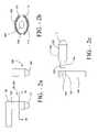
- FIG. 2 ais a side view of a portion of the embodiment of the invention of FIG. 2 ;
- FIG. 2 bis a cross-sectional view of the embodiment of the invention of FIG. 2 a taken through line 2 b — 2 b.
- FIG. 2 cis a side view of an embodiment of the invention having interchangeable prongs of different sizes.
- FIG. 2 dis a side view of an embodiment of the invention having interchangeable sleeves of different sizes that fit over the prongs.
- FIG. 2 eis a cross-sectional view of a sleeve of the embodiment of the invention of FIG. 2 d.
- FIG. 2 fis a side view of yet another embodiment of the invention with the prongs being pivotable.
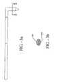
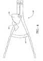
- FIG. 3is a plain view of yet another embodiment of the present invention.
- FIG. 3 ais a side view of the embodiment of the invention of FIG. 3 .
- FIG. 3 bis a cross-sectional view of the embodiment of the invention of FIG. 3 a taken through line 3 b — 3 b.
- FIG. 3 cis a perspective view of an embodiment of the invention which has some of the features depicted in FIG. 3 .
- FIG. 4is a plain view of a locking mechanism of an embodiment of the present invention.
- FIG. 4 ais a perspective view of an embodiment of the invention similar to FIG. 4 with a locking mechanism.
- FIGS. 1 and 2Embodiment of FIGS. 1 and 2 :
- the tool 100 , 104is a open,distraction adjacent spinous processed is depicted.
- the tool 100has a first distraction prong 102 and a second distraction prong 104 .
- the first distraction prong 102 and the second distraction prong 104can be seperated to distract an initial opening between adjacent spinous processes.
- the first distracting prong 102has a first tip 108 and the second distracting prong 104 has a second tip 110 .
- FIG. 1depicts the prongs 102 , 104 in an open, distracting position.
- FIG. 2shows the prongs 102 , 104 closed, with inner surfaces of the prongs 102 , 104 touching each other.
- the inner surfaces 113 , 115are flat in this embodiment.
- the surface 113 , 115( FIG. 2 b ) can be concave and of a shape to accept an implant 190 so that the implant 190 can be inserted between the spinous processes with the tool 100 and the prongs 102 , 104 still in place between and distracting spinous processes. After the implant 190 is positioned the tool 100 is removed.
- the prongs 102 , 104when placed together form the shape of an implant 190 .
- the shape in this embodimenthas a lead-in nose, or guide or tissue expander 117 ( FIG. 2 a ).
- This tissue expander 117includes a cone shape corresponding to the tissue expander 197 of the implant 190 , which has in a preferred embodiment an increasing elliptical cross section from a distal end to a place where the tissue expander 117 meets the main body 123 .
- the main body 123is also preferably elliptical in shape.
- the first distracting prong 102 and the second distracting prong 104are manufactured from a biologically acceptable material, such as titanium or stainless steel.
- the first tip 108 and the second tip 110are separate pivotable or swivelable components attached to the first distracting prong 102 and second distracting prong 104 .
- the main body 123is pivotably secured to the rest of the prong by a pin 125 extending through a; bore of the prong 102 , with a stop 127 keeping the pin in place.
- the physicianhas additional degrees of freedom to manipulate the handle 106 of the tool as he urges the prongs 102 , 104 between adjacent spinous process.
- the first tip 108 and the second tip 110are interchangeable.
- the first tip 108 and the second tip 110can be replaced with a new first tip 108 and new second tip 110 of a different size, defining a larger or smaller diameter or with a different shape.
- the tips 108 , 110can be interchangeable with other pairs of tips that when mated together form the approximate shape of one of an implant which is a 6 millimeters, 8 millimeters, 10 millimeters, 12 millimeters, or 14 millimeters implant.
- the distance in millimetersis that of the spacing or height between adjacent spinous processes. It is to be understood that in the preferred embodiment as shown in FIG. 2 , that the prongs and in particular the permanent tips are shaped to approximate a 10 millimeter implant.
- the 10 millimeter height as seen in FIG. 2is represented by distance “d.”
- the interchangeable tips 108 , 110can include a stem 129 which fits through a bore 131 of the prong 102 .
- a ball type detent 133can be used to secure the tip 108 by having the ball 133 of the detent be received in a groove 135 located on the stem 129 of the removable tip 108 .
- the tip 108has a cross-section of half of an elliptical shape and thus the stem 129 can have the same shape or can have another shape and fall within the scope of the invention.
- the tip 108can itself include a ball type detent 137 .
- the tip 108is preferably smaller than the smallest of the preferred sizes, which would be 6 millimeters. That being the case, sleeves 139 can be provided which fit over the end 108 in order to increase the diameter of the end 108 .
- the sleeve 139has an internal shape which can accept the end 108 and a bore 141 which will accept the ball of the detent 137 in order to secure the sleeve 139 in position over the end 108 .
- Sleeves of varying sizescan be provided in order to accommodate individuals with different anatomical shapes.
- sleeveswhich can be used in conjunction with implants having heights of 6 millimeters, 8 millimeters, 10 millimeters, 12 millimeters and 14 millimeters. It is also to be understood that the sleeve 139 would have a cross-section as shown in FIGS. 1 and 2 , that being half of an elliptical shape in this particular embodiment. As demonstrated above, the sleeves can have other shapes.
- the tips 108 , 110are provided at about 90° to the rest of the body of the tool 100 . It is to be understood that these tips can be provided at other angles both acute and obtuse in order to assist the physician in placing the tips between adjacent spinous processes, in order to distract apart the spinous processes.
- the handle 106includes a first member 105 and a second member 107 , pivotally connected by a fastener 109 .
- the handleis connected by a linkage 195 to the first and second prongs 102 , 104 .
- the distance from pivot fastener 109 to the below discussed gauge 112is greater than the distance between pivot fastener 109 and the below discussed fastener 119 .
- the first member 105 and second member 107each have scallops 111 for use by a physician in order to grip the handle 106 .
- a leaf spring 114is connected between the first member 105 and the second member 107 of the handle 106 .
- the leaf spring 114biases the handle 106 into an open position, keeping the first prong 102 and the second prong 104 normally closed.
- the leaf spring 114also provides resistance to closing the handle 106 .
- other mechanical devicessuch as a coil spring, by way of example, can be used to bias the handle 106 to an open position and provide resistance in closing the handle 106 .
- an individualTo spread the first distracting prong 102 and the second distracting prong 104 apart, an individual must urge the first member 105 and the second member 107 of the handle 106 together.
- the tool 100also has a gauge 112 .
- the gauge 112indicates the distance between the first distracting prong 102 and the second distracting prong 104 , which corresponds to the diameter of the opening created between the adjacent spinous processes.
- the gauge 112is connected at one end to the first member 105 and passes through the second member 107 , extending beyond the second member 107 .
- the gauge 112can be a threaded screw which is attached to the first member 105 and passes through the second member 107 .
- a fastener 141engages the threaded screw adjacent to the second member 107 and limits the movement of the first and second members 105 , 107 . Further a stop 117 limits the amount of distraction possible with prongs 102 , 104 .
- the position of the fastener 141 on the gauge 112allows a physician to measure the amount by which the handle 106 , and thus the amount by which the first prong 102 and the second prong 104 are spread apart in order to distract the space between spinous processes. While distracting the opening, the numbers or markings 143 on gauge 112 that are intercepted by the second member 107 corresponds to the diameter of the opening.
- the markings 143are set to indicate prong openings of 6 mm, 8 mm, 10 mm, 12 mm and 14 mm.
- the gauge 112can also increment the first distracting prong 102 and the second distracting prong 104 a known distance apart by rotating the fastener 141 in given amounts.
- the tool 100has a linkage 115 that interconnects prongs 102 , 114 with the handle. This linkage ensures, in this preferred embodiment, that the first distracting prong 102 and the second distracting prong 104 spread apart in a substantially parallel fashion. As discussed below, other embodiments ( FIG. 3 ) operate in a manner that the prongs are not opened and maintained in a parallel orientation.
- the linkage 195contains a first cross-link 116 and a second cross-link 118 .
- the first cross-link 116 and the second cross-link 118are pivotally mounted to each other at pivot 145 .
- the first cross-link 116 and the second cross-link 118have a first end 147 and a second end 149 .
- the first end 147 of both the first cross-link 116 and the second cross-link 118are pivotally connected with the handle 106 by pivot fasteners 119 .
- the second end 121 of both the first cross-link 116 and the second cross-link 118slidably engage a slot 120 located in links 151 and 153 of linkage 115 .
- Links 151 and 153are pivotally pined to first and second members 105 , 107 of handle 106 by pivot fasteners 155 at one end, and the prongs 102 , 104 extend from links 151 , 153 at the other end thereof. Accordingly, with this linkage arrangement 115 , the first distracting prong 102 and second distracting prong 104 are limited to substantially parallel motion with respect to each other.
- FIGS. 1 and 2The method of operation of the embodiment of the invention FIGS. 1 and 2 as used by the physician is as follows. After the surgical site between adjacent spinous processes is located, the surgeon can insert the prong distraction ends between the spinous processes using the tissue expansion portion of the ends in order to guide the distracting ends between the spinous processes. After this has occurred, a surgeon can squeeze on the handle 106 in order to urge the prongs apart, thereby distracting the space between the spinous processes. Using the gauge, the surgeon can determine the amount of the distraction, and if required, lock in the distraction by turning the knob which is part of the gauge. Generally in this embodiment, the handle would be moved to a closed position with one hand while the physician can use the other hand to adjust the gauge.
- the surgeoncould urge the handle to a closed position by turning the knob with the gauge. This would give a more exact, incremental way of adjusting the distraction between the spinous processes.
- the physiciancan determine which size of implant is appropriate for the space. Further if desired, and using tip 108 , 110 of FIG. 2 b , the physician could then further distract the space in order to create a opening large enough between the distraction prongs in order to slip in an implant between the prongs in the over-distracted position.
- the tool 100can be removed from between the spinous processes with the implant left in place. This procedure would only be used in a situation where it would be acceptable to over-distract the spinous processes. If that is not desirable, then the technique of using the tool 100 to guide the implant in place would not be used.
- the distracting tool 200has a first distracting prong 202 and a second distracting prong 204 .
- Prongs 202 , 204are pivotally connected at pivot point 245 .
- the first distracting prong 202has a first distracting end or element 208 .
- the second distracting prong 204has a second distracting end or element 210 .
- Both the first distracting element 208 and the second distracting element 210extend out at a substantially 90° angle from the first and second distracting prongs 202 , 204 in a preferred embodiment FIGS. 3 a , 3 c )
- the first distracting element 208 and the second distracting element 210form the approximate shape of an implant to be inserted into the patient.
- the first distracting end or element 208 and the second distracting end or element 210can have all the features and functionality as previously discussed with respect to prongs 102 , 104 and the ends or elements 108 , 110 of FIGS. 1 and 2 .
- the first distracting element 208 and the second distracting element 210can swivel and/or be detachable.
- the distracting tool 200also has a handle 206 .
- the handle 206is pivotally connected with the first prong 202 and the second prong 204 at pivot points 255 . Similar to the previously described embodiments, the first distracting element 208 and the second distracting element 210 are separated by urging handle element 205 , 207 of the handle 206 together. Handle element 205 and 207 are pivotally connected at pivot point 209 .
- the handle 206has a first hand stop 214 and a second hand stop 216 so that a physician may comfortably and positively place his hand around the handle 206 .
- the distracting tool 200also has a gauge 212 .
- the gauge 212is connected with the handle 206 so as to indicate the distance between the first distraction element 208 and the second distraction element 210 .
- the gaugecan indicate whether the size of the opening between the adjacent spinous processes is 6 millimeters, 8 millimeters, 10 millimeters, 12 millimeters, or 14 millimeters and/or can accommodate an implant of height 6 millimeters, 8 millimeters, 10 millimeters, 12 millimeters, or 14 millimeters.
- Indicia 213are set to these measurements.
- gauge 212has a curved base 215 including the indicia 213 , with the base 215 affixed to handle element 205 .
- Base 215moves relative to handle element 207 .
- Flags or pointers 215are fixed to handle element 207 and indicate a measurement as base 215 moves thereby.
- the gauge 212has a distracting limiter or stop 217 to prevent the handle 206 from being closed beyond a specific limit.
- the stop 217is placed on the underside of base 215 and as the handle 206 is urged to a closed position, the stop 217 contracts handle element 207 and prevents further closure of the handle 206 and thus further spreading apart of elements 208 , 210 .
- distraction of the spinous processesis limited.
- the largest implant typically required to be inserted between adjacent spinous processesis 14 millimeters.
- the distracting limiter 217is located below the 14 millimeters mark on the underside of the gauge 212 . The distracting limiter 217 thus prevents the first distraction element 208 and the second distraction element 210 from spreading apart and creating an opening between the spinous process with a diameter greater than 14 millimeters.
- FIG. 3can be operated in a fashion somewhat similar to that of the embodiment of FIGS. 1 and 2 .
- the distracting elements 208 , 210are not maintained in a parallel orientation. As these elements are opened to heights of upwards of 14 millimeters and it has been found that appropriate distraction can be obtained with the distracting elements 208 , 210 not totally maintained in a parallel orientation.
- gauge 212the amount of distraction of the spinous processes is determined by gauge 212 .
- the tool 200can be locked, holding the distraction at the desired height.
- the physiciancan then know the desired height of implant to be selected for implantation.
- the implantcan then be selected from a tray of implants.
- the tool 200can then be removed and the process of inserting the implant precedes as disclosed in one the above U.S. patents.
- the first hand grip 214contains a locking mechanism 220 such as the embodiment seen in FIG. 3 or the embodiment seen in FIG. 4 .
- the locking mechanism 220 of FIG. 4includes a spring-biased and pivotable pawl 222 and a ratchet wheel 224 .
- the pawl 222has several teeth which engage and interlock with the corresponding teeth of the ratchet wheel 224 when pawl is moved.
- the pawl (not shown) in FIG. 3can engage and disengage the ratchet wheel (not shown) by sliding the trigger 218 between a locked and unlocked position.
- the trigger 218is placed on the handle 206 such that the trigger 218 can be slidably controlled with a single finger or the thumb.
- the physicancan maintain the same grip on the handle 206 with only one hand throughout the entire process.
- the physiciancan insert the first distracting element 208 and the second distracting element 210 between adjacent spinous process in order to create a first distraction.
- the handle 206can then be closed to further distract the initial opening.
- the physiciancan lock the handle 206 in place by sliding or pushing the trigger 218 into the locked position.
- FIG. 4 adepicts a slightly different embodiment of the invention than that depicted in FIG. 3 .
- similar elementshave similar numbers.
- the ratchet wheelis embodied in teeth 240 located on the upper or lower edge of the gauge 212 and the pawl is incorporated in the pivotable trigger 218 .
- FIG. 3 cdepicts an embodiment of the invention with a gauge 212 as depicted in FIG. 3 and a locking mechanism 112 , which can be designed to also include a gauge, as depicted in FIG. 1 . Similar elements have similar numbers.
- the present inventionincludes a method of sizing, and distracting an opening, and subsequently and alternatively installing an implant device between adjacent spinous processes.
- a physicianwill first create an initial opening in the body tissue between the adjacent spinous processes.
- a physiciancan then insert the ends or distracting elements the first distracting prong 102 and the second distracting prong 104 into the initial opening.
- the physiciancan continuously read the gauge 112 to determine the distance between the first distracting prong 102 and the second distracting prong 104 .
- the physiciandoes not have to remove the tool 100 to measure the diameter of the opening.
- the tool 100When the physician distracts the opening to the desired diameter, the tool 100 can be locked in place. The physician can then select an implant with a similar diameter. The physician can then remove the tool 100 and insert the implant as described in cases of the above referenced patents. Alternatively, if appropriate, while the first distracting prong 102 and the second distracting prong 104 are still within the opening, the physician can then urge the implant between the first distracting tip 108 and the second distracting tip 110 . As mentioned previously the first tip 108 and the second tip 110 form a channel to guide the implant. To leave the implant within the patient, the physician can remove the tool 100 from between the adjacent spinous processes.
- a physiciancan insert the first distraction element 208 and the second distraction element 210 into the opening.
- the gauge 212indicates the diameter of the opening.
- the handle 206can be locked into place. By sliding the trigger 218 into the “locked” position, the first destruction element 208 and the second distraction element 210 are locked in place. Selecting an appropriately sized implant, inserting the implant and removing the tool 200 are all similar to the previously described embodiment.
Landscapes
- Health & Medical Sciences (AREA)
- Orthopedic Medicine & Surgery (AREA)
- Neurology (AREA)
- Life Sciences & Earth Sciences (AREA)
- Veterinary Medicine (AREA)
- Surgery (AREA)
- Animal Behavior & Ethology (AREA)
- General Health & Medical Sciences (AREA)
- Public Health (AREA)
- Chemical & Material Sciences (AREA)
- Medicinal Chemistry (AREA)
- Pharmacology & Pharmacy (AREA)
- Nuclear Medicine, Radiotherapy & Molecular Imaging (AREA)
- Epidemiology (AREA)
- Engineering & Computer Science (AREA)
- Biomedical Technology (AREA)
- Heart & Thoracic Surgery (AREA)
- Medical Informatics (AREA)
- Molecular Biology (AREA)
- Prostheses (AREA)
Abstract
Description
Claims (4)
Priority Applications (3)
| Application Number | Priority Date | Filing Date | Title |
|---|---|---|---|
| US09/999,754US7189234B2 (en) | 1998-10-20 | 2001-10-31 | Interspinous process implant sizer and distractor with a split head and size indicator and method |
| PCT/US2002/029019WO2003024298A2 (en) | 2001-09-18 | 2002-09-12 | Interspinous process implant sizer and distractor with a split head and size indicator and method |
| AU2002335744AAU2002335744A1 (en) | 2001-09-18 | 2002-09-12 | Interspinous process implant sizer and distractor with a split head and size indicator and method |
Applications Claiming Priority (8)
| Application Number | Priority Date | Filing Date | Title |
|---|---|---|---|
| US09/175,645US6068630A (en) | 1997-01-02 | 1998-10-20 | Spine distraction implant |
| US09/179,570US6048342A (en) | 1997-01-02 | 1998-10-27 | Spine distraction implant |
| US09/474,037US6190387B1 (en) | 1997-01-02 | 1999-12-28 | Spine distraction implant |
| US09/473,173US6235030B1 (en) | 1997-01-02 | 1999-12-28 | Spine distraction implant |
| US09/799,470US6902566B2 (en) | 1997-01-02 | 2001-03-05 | Spinal implants, insertion instruments, and methods of use |
| US09/799,215US7101375B2 (en) | 1997-01-02 | 2001-03-05 | Spine distraction implant |
| US32350801P | 2001-09-18 | 2001-09-18 | |
| US09/999,754US7189234B2 (en) | 1998-10-20 | 2001-10-31 | Interspinous process implant sizer and distractor with a split head and size indicator and method |
Related Parent Applications (6)
| Application Number | Title | Priority Date | Filing Date |
|---|---|---|---|
| US09/175,645Continuation-In-PartUS6068630A (en) | 1997-01-02 | 1998-10-20 | Spine distraction implant |
| US09/179,570ContinuationUS6048342A (en) | 1997-01-02 | 1998-10-27 | Spine distraction implant |
| US09/474,037Continuation-In-PartUS6190387B1 (en) | 1997-01-02 | 1999-12-28 | Spine distraction implant |
| US09/473,173Continuation-In-PartUS6235030B1 (en) | 1997-01-02 | 1999-12-28 | Spine distraction implant |
| US09/799,470Continuation-In-PartUS6902566B2 (en) | 1997-01-02 | 2001-03-05 | Spinal implants, insertion instruments, and methods of use |
| US09/799,215Continuation-In-PartUS7101375B2 (en) | 1997-01-02 | 2001-03-05 | Spine distraction implant |
Publications (2)
| Publication Number | Publication Date |
|---|---|
| US20020072752A1 US20020072752A1 (en) | 2002-06-13 |
| US7189234B2true US7189234B2 (en) | 2007-03-13 |
Family
ID=26983995
Family Applications (1)
| Application Number | Title | Priority Date | Filing Date |
|---|---|---|---|
| US09/999,754Expired - Fee RelatedUS7189234B2 (en) | 1998-10-20 | 2001-10-31 | Interspinous process implant sizer and distractor with a split head and size indicator and method |
Country Status (3)
| Country | Link |
|---|---|
| US (1) | US7189234B2 (en) |
| AU (1) | AU2002335744A1 (en) |
| WO (1) | WO2003024298A2 (en) |
Cited By (109)
| Publication number | Priority date | Publication date | Assignee | Title |
|---|---|---|---|---|
| US20040215343A1 (en)* | 2000-02-28 | 2004-10-28 | Stephen Hochschuler | Method and apparatus for treating a vertebral body |
| US20060004380A1 (en)* | 2004-07-02 | 2006-01-05 | Didomenico Scott R | Compressor-distractor |
| US20060084838A1 (en)* | 2004-10-04 | 2006-04-20 | Norikata Takuma | Instrument for re-insertion of a gastrostoma tube |
| US20060149379A1 (en)* | 2000-07-21 | 2006-07-06 | Spineology, Inc. | Expandable porous mesh bag device and methods of use for reduction, filling, fixation and supporting of bone |
| US20060195102A1 (en)* | 2005-02-17 | 2006-08-31 | Malandain Hugues F | Apparatus and method for treatment of spinal conditions |
| US20060195109A1 (en)* | 2000-02-22 | 2006-08-31 | Mcgahan Thomas V | Instruments and techniques for disc space preparation |
| US20060247637A1 (en)* | 2004-08-09 | 2006-11-02 | Dennis Colleran | System and method for dynamic skeletal stabilization |
| US20060282079A1 (en)* | 2005-06-10 | 2006-12-14 | Depuy Spine, Inc. | Posterior dynamic stabilization systems and methods |
| US20070043361A1 (en)* | 2005-02-17 | 2007-02-22 | Malandain Hugues F | Percutaneous spinal implants and methods |
| US20070049934A1 (en)* | 2005-02-17 | 2007-03-01 | Edidin Avram A | Percutaneous spinal implants and methods |
| US20070049935A1 (en)* | 2005-02-17 | 2007-03-01 | Edidin Avram A | Percutaneous spinal implants and methods |
| US20070203493A1 (en)* | 1997-01-02 | 2007-08-30 | Zucherman James F | Spine distraction implant and method |
| US20080039858A1 (en)* | 1997-01-02 | 2008-02-14 | Zucherman James F | Spine distraction implant and method |
| US20080046087A1 (en)* | 2004-09-23 | 2008-02-21 | Zucherman James F | Interspinous process implant including a binder and method of implantation |
| US20080071376A1 (en)* | 2005-02-17 | 2008-03-20 | Kohm Andrew C | Percutaneous spinal implants and methods |
| US20080077156A1 (en)* | 2006-09-25 | 2008-03-27 | Erik Emstad | Surgical distractor and delivery instrument |
| USD568470S1 (en)* | 2006-09-13 | 2008-05-06 | Karl Storz Gmbh & Co. Kg | Medical instrument |
| US20080147190A1 (en)* | 2006-12-14 | 2008-06-19 | Warsaw Orthopedic, Inc. | Interspinous Process Devices and Methods |
| US20080172057A1 (en)* | 1997-01-02 | 2008-07-17 | Zucherman James F | Spine distraction implant and method |
| US20080177272A1 (en)* | 2005-03-21 | 2008-07-24 | Zucherman James F | Interspinous process implant having deployable wing and method of implantation |
| US20080183211A1 (en)* | 2007-01-11 | 2008-07-31 | Lanx, Llc | Spinous process implants and associated methods |
| US20090018556A1 (en)* | 2004-04-16 | 2009-01-15 | Memometal Technologies | Clamp for positioning a superelastic osteosynthesis clip |
| US20090054988A1 (en)* | 2007-05-01 | 2009-02-26 | Harold Hess | Interspinous implants and methods for implanting same |
| US20090149886A1 (en)* | 2007-11-02 | 2009-06-11 | Taurus Gmbh & Co. Kg | Implantation |
| US20090198245A1 (en)* | 2008-02-04 | 2009-08-06 | Phan Christopher U | Tools and methods for insertion and removal of medical implants |
| US20090222043A1 (en)* | 2004-10-20 | 2009-09-03 | Moti Altarac | Interspinous process spacer instrument system with deployment indicator |
| US20090275952A1 (en)* | 2008-05-05 | 2009-11-05 | Ranier Limited | Distractor |
| US20090292316A1 (en)* | 2007-05-01 | 2009-11-26 | Harold Hess | Interspinous process implants having deployable engagement arms |
| US20100010494A1 (en)* | 2008-07-11 | 2010-01-14 | Q-Spine, Llc | Spinal measuring device and distractor |
| US20100011916A1 (en)* | 2008-07-17 | 2010-01-21 | Cmr, Inc. | Lever divice |
| WO2010025296A1 (en)* | 2008-08-28 | 2010-03-04 | Q-Spine Llc | Apparatus and methods for inter-operative verification of appropriate spinal prosthesis size and placement |
| US20100100183A1 (en)* | 2008-10-15 | 2010-04-22 | Ann Prewett | Swellable interspinous stabilization implant |
| US20100114166A1 (en)* | 2008-11-05 | 2010-05-06 | Andrew Kohm | Extension limiting devices and methods of use for the spine |
| US20100152855A1 (en)* | 2000-07-21 | 2010-06-17 | Kuslich Stephen D | Expandable porous mesh bag device and methods of use for reduction, filling, fixation and supporting of bone |
| US20100168860A1 (en)* | 2008-12-22 | 2010-07-01 | Marc Reichen | Orthopedic implant with flexible keel |
| US7763073B2 (en) | 2004-03-09 | 2010-07-27 | Depuy Spine, Inc. | Posterior process dynamic spacer |
| US20100234889A1 (en)* | 2009-03-13 | 2010-09-16 | Harold Hess | Interspinous Process Implant and Fusion Cage Spacer |
| WO2010123702A1 (en)* | 2009-04-24 | 2010-10-28 | Kyphon Sarl, | Distraction tool for distracting an interspinous space |
| US20100274159A1 (en)* | 2009-03-18 | 2010-10-28 | Contipi Ltd. | Device and method for fitting a pessary |
| WO2010129133A1 (en) | 2009-05-08 | 2010-11-11 | Kyphon Sarl, | Distraction tool for distracting an interspinous space |
| US7854752B2 (en) | 2004-08-09 | 2010-12-21 | Theken Spine, Llc | System and method for dynamic skeletal stabilization |
| US20110093022A1 (en)* | 2003-12-17 | 2011-04-21 | Runco Thomas J | Instruments and Methods for Bone Anchor Engagement and Spinal Rod Reduction |
| US20110098538A1 (en)* | 2009-10-23 | 2011-04-28 | Beaver-Visitec International (Us), Inc. | Speculum |
| US20110106160A1 (en)* | 2004-10-20 | 2011-05-05 | The Board Of Trustees Of The Leland Stanford Junior University | Systems and methods for posterior dynamic stabilization of the spine |
| US20110112568A1 (en)* | 2009-08-28 | 2011-05-12 | The Penn State Research Foundation | Surgical tool |
| US20110138973A1 (en)* | 2009-12-10 | 2011-06-16 | Tian Shoei Wang | Flat clamping hand tool structure |
| US8096994B2 (en) | 2005-02-17 | 2012-01-17 | Kyphon Sarl | Percutaneous spinal implants and methods |
| US20120035638A1 (en)* | 2009-03-26 | 2012-02-09 | Vickneswaran Mathaneswaran | Apparatus for surgery |
| US8167890B2 (en) | 2005-02-17 | 2012-05-01 | Kyphon Sarl | Percutaneous spinal implants and methods |
| US20120109014A1 (en)* | 2010-11-01 | 2012-05-03 | Coopersurgical, Inc. | Cervical Sizing Devices and Related Kits and Methods |
| US8267957B1 (en) | 2007-12-14 | 2012-09-18 | Holmed Corporation | Compressor with extended ratchet bar feature |
| US20120290094A1 (en)* | 2002-06-25 | 2012-11-15 | Warsaw Orthopedic, Inc. | Minimally invasive expanding spacer and method |
| US8365377B1 (en)* | 2009-08-21 | 2013-02-05 | James Basiliere | Pipe joining tool |
| US8425560B2 (en) | 2011-03-09 | 2013-04-23 | Farzad Massoudi | Spinal implant device with fixation plates and lag screws and method of implanting |
| US8496689B2 (en) | 2011-02-23 | 2013-07-30 | Farzad Massoudi | Spinal implant device with fusion cage and fixation plates and method of implanting |
| US8562681B2 (en) | 2012-01-31 | 2013-10-22 | Styker Spine | Laminoplasty implant, method and instrumentation |
| WO2014078798A1 (en)* | 2012-11-16 | 2014-05-22 | Southern Spine, Llc | Linkage systems for interspinous process spacing device |
| US8740948B2 (en) | 2009-12-15 | 2014-06-03 | Vertiflex, Inc. | Spinal spacer for cervical and other vertebra, and associated systems and methods |
| US8840617B2 (en) | 2010-02-26 | 2014-09-23 | Warsaw Orthopedic, Inc. | Interspinous process spacer diagnostic parallel balloon catheter and methods of use |
| US8845726B2 (en) | 2006-10-18 | 2014-09-30 | Vertiflex, Inc. | Dilator |
| US8864828B2 (en) | 2004-10-20 | 2014-10-21 | Vertiflex, Inc. | Interspinous spacer |
| US8900271B2 (en) | 2004-10-20 | 2014-12-02 | The Board Of Trustees Of The Leland Stanford Junior University | Systems and methods for posterior dynamic stabilization of the spine |
| US9039742B2 (en) | 2004-10-20 | 2015-05-26 | The Board Of Trustees Of The Leland Stanford Junior University | Systems and methods for posterior dynamic stabilization of the spine |
| US9055981B2 (en) | 2004-10-25 | 2015-06-16 | Lanx, Inc. | Spinal implants and methods |
| US9095379B2 (en) | 2005-03-04 | 2015-08-04 | Medos International Sarl | Constrained motion bone screw assembly |
| US9101416B2 (en) | 2003-01-24 | 2015-08-11 | DePuy Synthes Products, Inc. | Spinal rod approximator |
| US9119680B2 (en) | 2004-10-20 | 2015-09-01 | Vertiflex, Inc. | Interspinous spacer |
| US9125692B2 (en) | 2004-10-20 | 2015-09-08 | The Board Of Trustees Of The Leland Stanford Junior University | Systems and methods for posterior dynamic stabilization of the spine |
| US9149306B2 (en) | 2011-06-21 | 2015-10-06 | Seaspine, Inc. | Spinous process device |
| US9155570B2 (en) | 2004-10-20 | 2015-10-13 | Vertiflex, Inc. | Interspinous spacer |
| US9155572B2 (en) | 2004-10-20 | 2015-10-13 | Vertiflex, Inc. | Minimally invasive tooling for delivery of interspinous spacer |
| US9161783B2 (en) | 2004-10-20 | 2015-10-20 | Vertiflex, Inc. | Interspinous spacer |
| US9168073B2 (en) | 2013-03-15 | 2015-10-27 | DePuy Synthes Products, Inc. | Spinous process fixator |
| US9211146B2 (en) | 2004-10-20 | 2015-12-15 | The Board Of Trustees Of The Leland Stanford Junior University | Systems and methods for posterior dynamic stabilization of the spine |
| US9247968B2 (en) | 2007-01-11 | 2016-02-02 | Lanx, Inc. | Spinous process implants and associated methods |
| US9265538B2 (en) | 2007-09-28 | 2016-02-23 | DePuy Synthes Products, Inc. | Dual pivot instrument for reduction of a fixation element and method of use |
| US9283005B2 (en) | 2004-10-20 | 2016-03-15 | Vertiflex, Inc. | Systems and methods for posterior dynamic stabilization of the spine |
| US9314279B2 (en) | 2004-10-20 | 2016-04-19 | The Board Of Trustees Of The Leland Stanford Junior University | Systems and methods for posterior dynamic stabilization of the spine |
| US9326798B2 (en) | 2008-03-10 | 2016-05-03 | DePuy Synthes Products, Inc. | Derotation instrument with reduction functionality |
| US9393055B2 (en) | 2004-10-20 | 2016-07-19 | Vertiflex, Inc. | Spacer insertion instrument |
| US9572603B2 (en) | 2004-10-20 | 2017-02-21 | Vertiflex, Inc. | Interspinous spacer |
| US20170100138A1 (en)* | 2012-11-16 | 2017-04-13 | Southern Spine, Llc | Rasp Tool |
| US9662150B1 (en) | 2007-02-26 | 2017-05-30 | Nuvasive, Inc. | Spinal stabilization system and methods of use |
| US9675303B2 (en) | 2013-03-15 | 2017-06-13 | Vertiflex, Inc. | Visualization systems, instruments and methods of using the same in spinal decompression procedures |
| US9730741B2 (en) | 2013-12-30 | 2017-08-15 | Monsour Vincent Makhlouf | Temporarily secured bone reduction clamp |
| US9743960B2 (en) | 2007-01-11 | 2017-08-29 | Zimmer Biomet Spine, Inc. | Interspinous implants and methods |
| US9757164B2 (en) | 2013-01-07 | 2017-09-12 | Spinal Simplicity Llc | Interspinous process implant having deployable anchor blades |
| US9814496B2 (en) | 2015-09-15 | 2017-11-14 | Hydra Medical, LLC | Interspinous stabilization implant |
| US9861399B2 (en) | 2009-03-13 | 2018-01-09 | Spinal Simplicity, Llc | Interspinous process implant having a body with a removable end portion |
| US9907579B2 (en) | 2008-08-13 | 2018-03-06 | DePuy Synthes Products, Inc. | Interspinous spacer assembly |
| US9907551B2 (en) | 2014-08-04 | 2018-03-06 | Howmedica Osteonics Corp. | Surgical instrument for implanting fixation device |
| US10010321B2 (en) | 2013-03-13 | 2018-07-03 | Stryker European Holdings I, Llc | Adjustable forceps for osteosynthesis clip |
| US10292738B2 (en) | 2004-10-20 | 2019-05-21 | The Board Of Trustees Of The Leland Stanford Junior University | Systems and methods for stabilizing the motion or adjusting the position of the spine |
| US10314624B2 (en) | 2005-03-04 | 2019-06-11 | DePuy Synthes Products, Inc. | Instruments and methods for manipulating vertebra |
| US10335207B2 (en) | 2015-12-29 | 2019-07-02 | Nuvasive, Inc. | Spinous process plate fixation assembly |
| US10478313B1 (en) | 2014-01-10 | 2019-11-19 | Nuvasive, Inc. | Spinal fusion implant and related methods |
| US10524772B2 (en) | 2014-05-07 | 2020-01-07 | Vertiflex, Inc. | Spinal nerve decompression systems, dilation systems, and methods of using the same |
| US10792078B2 (en) | 2010-03-12 | 2020-10-06 | Southern Spine, Llc | Interspinous process spacing device |
| US10973556B2 (en) | 2008-06-17 | 2021-04-13 | DePuy Synthes Products, Inc. | Adjustable implant assembly |
| US11291481B2 (en) | 2019-03-21 | 2022-04-05 | Medos International Sarl | Rod reducers and related methods |
| US11291482B2 (en) | 2019-03-21 | 2022-04-05 | Medos International Sarl | Rod reducers and related methods |
| USD1004774S1 (en) | 2019-03-21 | 2023-11-14 | Medos International Sarl | Kerrison rod reducer |
| US11812923B2 (en) | 2011-10-07 | 2023-11-14 | Alan Villavicencio | Spinal fixation device |
| US11832855B2 (en) | 2017-12-15 | 2023-12-05 | Medos International Sårl | Unilateral implant holders and related methods |
| US12102542B2 (en) | 2022-02-15 | 2024-10-01 | Boston Scientific Neuromodulation Corporation | Interspinous spacer and methods and systems utilizing the interspinous spacer |
| US12133664B2 (en) | 2022-12-13 | 2024-11-05 | Spinal Simplicity, Llc | Medical implant |
| US12318121B2 (en) | 2020-11-09 | 2025-06-03 | Medos International Sàrl | Biplanar forceps reducers and methods of use |
| US12390340B2 (en) | 2023-03-15 | 2025-08-19 | Boston Scientific Neuromodulation Corporation | Interspinous spacer with a range of deployment positions and methods and systems |
| US12433646B2 (en) | 2023-02-21 | 2025-10-07 | Boston Scientific Neuromodulation Corporation | Interspinous spacer with actuator locking arrangements and methods and systems |
Families Citing this family (74)
| Publication number | Priority date | Publication date | Assignee | Title |
|---|---|---|---|---|
| US6936071B1 (en) | 1999-07-02 | 2005-08-30 | Spine Solutions, Inc. | Intervertebral implant |
| EP1792586B1 (en) | 1999-09-14 | 2012-12-26 | Spine Solutions Inc. | Insert instrument for an implant between vertebrae |
| US20040024291A1 (en)* | 2002-08-01 | 2004-02-05 | Zinkel John L. | Method and apparatus for spinal surgery |
| EP1542626B1 (en) | 2002-08-15 | 2012-09-26 | Synthes GmbH | Controlled artificial intervertebral disc implant |
| CA2495404C (en)* | 2002-08-15 | 2011-05-03 | Justin K. Coppes | Intervertebral disc implant |
| US7014617B2 (en)* | 2002-09-20 | 2006-03-21 | Depuy Acromed, Inc. | Pivoted tensiometer for measuring tension in an intervertebral disc space |
| WO2004032794A2 (en)* | 2002-10-10 | 2004-04-22 | Mekanika, Inc. | Apparatus and method for restoring biomechanical function to a motion segment unit of the spine |
| US7204852B2 (en) | 2002-12-13 | 2007-04-17 | Spine Solutions, Inc. | Intervertebral implant, insertion tool and method of inserting same |
| US7988698B2 (en) | 2003-01-28 | 2011-08-02 | Depuy Spine, Inc. | Spinal rod approximator |
| US7491204B2 (en)* | 2003-04-28 | 2009-02-17 | Spine Solutions, Inc. | Instruments and method for preparing an intervertebral space for receiving an artificial disc implant |
| US7320689B2 (en)* | 2003-07-15 | 2008-01-22 | Cervitech, Inc. | Multi-part cervical endoprosthesis with insertion instrument |
| US20050015095A1 (en)* | 2003-07-15 | 2005-01-20 | Cervitech, Inc. | Insertion instrument for cervical prostheses |
| US7803162B2 (en)* | 2003-07-21 | 2010-09-28 | Spine Solutions, Inc. | Instruments and method for inserting an intervertebral implant |
| US20050038511A1 (en)* | 2003-08-15 | 2005-02-17 | Martz Erik O. | Transforaminal lumbar interbody fusion (TLIF) implant, surgical procedure and instruments for insertion of spinal implant in a spinal disc space |
| US7252673B2 (en) | 2003-09-10 | 2007-08-07 | Warsaw Orthopedic, Inc. | Devices and methods for inserting spinal implants |
| US7608080B2 (en) | 2004-07-02 | 2009-10-27 | Warsaw Orthopedic, Inc. | Device for inserting implants |
| DE102004043995A1 (en)* | 2004-09-08 | 2006-03-30 | Aesculap Ag & Co. Kg | Surgical instrument |
| US7988699B2 (en)* | 2004-10-19 | 2011-08-02 | Warsaw Orthopedic, Inc. | Adjustable instrumentation for spinal implant insertion |
| US8012207B2 (en)* | 2004-10-20 | 2011-09-06 | Vertiflex, Inc. | Systems and methods for posterior dynamic stabilization of the spine |
| US8277488B2 (en) | 2004-10-20 | 2012-10-02 | Vertiflex, Inc. | Interspinous spacer |
| US8123782B2 (en) | 2004-10-20 | 2012-02-28 | Vertiflex, Inc. | Interspinous spacer |
| US8613747B2 (en) | 2004-10-20 | 2013-12-24 | Vertiflex, Inc. | Spacer insertion instrument |
| US7575579B2 (en)* | 2004-11-18 | 2009-08-18 | Union Surgical, Llc | Drill guide tissue protector |
| WO2006058221A2 (en) | 2004-11-24 | 2006-06-01 | Abdou Samy M | Devices and methods for inter-vertebral orthopedic device placement |
| US7625376B2 (en)* | 2005-01-26 | 2009-12-01 | Warsaw Orthopedic, Inc. | Reducing instrument for spinal surgery |
| US7722622B2 (en) | 2005-02-25 | 2010-05-25 | Synthes Usa, Llc | Implant insertion apparatus and method of use |
| US8496582B2 (en)* | 2005-04-01 | 2013-07-30 | Thomas R. Winston | Apparatus and method for expanding a chest cavity |
| US8668699B2 (en)* | 2005-04-14 | 2014-03-11 | Warsaw Orthopedic, Inc. | Multi-function orthopedic instrument |
| US7575580B2 (en)* | 2005-04-15 | 2009-08-18 | Warsaw Orthopedic, Inc. | Instruments, implants and methods for positioning implants into a spinal disc space |
| US20060247679A1 (en)* | 2005-04-29 | 2006-11-02 | Sdgi Holdings, Inc. | Compression device and method for shape memory alloy implants |
| US20060293692A1 (en)* | 2005-06-02 | 2006-12-28 | Whipple Dale E | Instruments and methods for manipulating a spinal fixation element |
| US8267970B2 (en)* | 2005-10-25 | 2012-09-18 | Depuy Spine, Inc. | Laminar hook spring |
| US8377072B2 (en) | 2006-02-06 | 2013-02-19 | Depuy Spine, Inc. | Medical device installation tool |
| DE102007018860B4 (en)* | 2006-04-28 | 2023-01-05 | Paradigm Spine L.L.C. | Instrument system for use with an interspinous implant |
| US8062337B2 (en)* | 2006-05-04 | 2011-11-22 | Warsaw Orthopedic, Inc. | Expandable device for insertion between anatomical structures and a procedure utilizing same |
| EP2078506A4 (en) | 2006-06-05 | 2011-11-09 | Traiber S L | Device for vertebral attachment and tool for fitting of the said device |
| EP3628244A1 (en) | 2006-07-24 | 2020-04-01 | Centinel Spine Schweiz GmbH | Intervertebral implant with keel |
| BRPI0714955A2 (en) | 2006-07-31 | 2013-07-23 | Systhes Gmbh | instrument system and method for preparing an intervertebral space to receive an implant, and milling guide for use with an instrument system |
| DE602007008112D1 (en)* | 2006-09-25 | 2010-09-09 | Stryker Spine | ALIGNMENT CONNECTION FOR BAR CONTOURING |
| US20080108990A1 (en)* | 2006-11-02 | 2008-05-08 | St. Francis Medical Technologies, Inc. | Interspinous process implant having a fixed wing and a deployable wing and method of implantation |
| US8012156B2 (en)* | 2006-11-17 | 2011-09-06 | Traiber, S.A. | Intersomatic cage, clamp for manipulating it and procedure for inserting the intersomatic cage between vertebrae |
| US20080234689A1 (en)* | 2007-02-21 | 2008-09-25 | Warsaw Orthopedic, Inc. | Vertebral Plate Measuring Device and Method of Use |
| US8486081B2 (en) | 2007-07-23 | 2013-07-16 | DePuy Synthes Products, LLC | Implant insertion device and method |
| US7887541B2 (en) | 2007-07-26 | 2011-02-15 | Depuy Spine, Inc. | Spinal rod reduction instruments and methods for use |
| US20090105773A1 (en)* | 2007-10-23 | 2009-04-23 | Warsaw Orthopedic, Inc. | Method and apparatus for insertion of an interspinous process device |
| US8142441B2 (en)* | 2008-10-16 | 2012-03-27 | Aesculap Implant Systems, Llc | Surgical instrument and method of use for inserting an implant between two bones |
| US8591587B2 (en) | 2007-10-30 | 2013-11-26 | Aesculap Implant Systems, Llc | Vertebral body replacement device and method for use to maintain a space between two vertebral bodies within a spine |
| US8241363B2 (en)* | 2007-12-19 | 2012-08-14 | Depuy Spine, Inc. | Expandable corpectomy spinal fusion cage |
| USD626649S1 (en)* | 2008-06-06 | 2010-11-02 | Atlas Spine, Inc. | Distractor |
| ITPI20090044A1 (en)* | 2009-04-22 | 2010-10-23 | Cousin Biotech S A S | INSTRUMENTARY FOR THE INSTALLATION OF AN INTERVERTEBRAL PROSTHESIS |
| US8764806B2 (en) | 2009-12-07 | 2014-07-01 | Samy Abdou | Devices and methods for minimally invasive spinal stabilization and instrumentation |
| US8777953B1 (en) | 2010-10-06 | 2014-07-15 | Greatbatch Ltd. | Rocker mechanism |
| US8882805B1 (en) | 2011-08-02 | 2014-11-11 | Lawrence Maccree | Spinal fixation system |
| US8845728B1 (en) | 2011-09-23 | 2014-09-30 | Samy Abdou | Spinal fixation devices and methods of use |
| US20130226240A1 (en) | 2012-02-22 | 2013-08-29 | Samy Abdou | Spinous process fixation devices and methods of use |
| US10448977B1 (en) | 2012-03-31 | 2019-10-22 | Ali H. MESIWALA | Interspinous device and related methods |
| US9011450B2 (en) | 2012-08-08 | 2015-04-21 | DePuy Synthes Products, LLC | Surgical instrument |
| US9198767B2 (en) | 2012-08-28 | 2015-12-01 | Samy Abdou | Devices and methods for spinal stabilization and instrumentation |
| US9320617B2 (en) | 2012-10-22 | 2016-04-26 | Cogent Spine, LLC | Devices and methods for spinal stabilization and instrumentation |
| DE102013200924A1 (en)* | 2013-01-22 | 2014-07-24 | Erich Johann Müller | Razor tool for minimally invasive prosthesis revision |
| US9724137B2 (en)* | 2014-03-19 | 2017-08-08 | Warsaw Orthopedic, Inc. | Surgical instrumentation and method |
| US10238434B2 (en) | 2014-03-20 | 2019-03-26 | Spinefrontier, Inc | System and method for spinal decompression |
| DE102014117176A1 (en)* | 2014-11-24 | 2016-05-25 | Aesculap Ag | Pedicle screw system and spine stabilization system |
| USD744097S1 (en)* | 2014-12-15 | 2015-11-24 | Integra Lifesciences Corporation | Orthopedic implant sizer |
| US9763685B2 (en)* | 2015-01-09 | 2017-09-19 | Gyrus Acmi, Inc. | Combination medical device |
| US10857003B1 (en) | 2015-10-14 | 2020-12-08 | Samy Abdou | Devices and methods for vertebral stabilization |
| CN105559836B (en)* | 2016-02-06 | 2019-08-20 | 贺新宁 | A kind of minimally invasive unfolding pressurizing device |
| CN105559869B (en)* | 2016-02-06 | 2019-08-20 | 贺新宁 | A kind of general percutaneous cervical arc root nail stick internal fixation system |
| US10744000B1 (en) | 2016-10-25 | 2020-08-18 | Samy Abdou | Devices and methods for vertebral bone realignment |
| US10973648B1 (en) | 2016-10-25 | 2021-04-13 | Samy Abdou | Devices and methods for vertebral bone realignment |
| US11419595B2 (en)* | 2017-05-19 | 2022-08-23 | Paradigm Spine, Llc | Interspinous, interlaminar space expander and measurement instrument |
| US11179248B2 (en) | 2018-10-02 | 2021-11-23 | Samy Abdou | Devices and methods for spinal implantation |
| US11406370B2 (en)* | 2019-03-19 | 2022-08-09 | Boss Instruments, Ltd., Inc. | Handle for retractor blade |
| KR102576432B1 (en)* | 2023-06-05 | 2023-09-08 | 주식회사 에스디에스 | Compressor for spinal implants |
Citations (139)
| Publication number | Priority date | Publication date | Assignee | Title |
|---|---|---|---|---|
| US2456806A (en)* | 1947-01-14 | 1948-12-21 | Erwin B Wolffe | Vaginal gauge |
| US2677369A (en) | 1952-03-26 | 1954-05-04 | Fred L Knowles | Apparatus for treatment of the spinal column |
| GB780652A (en) | 1954-04-30 | 1957-08-07 | Zimmer Orthopaedic Ltd | Improvements in or relating to apparatus for use in spinal fixation |
| US3426364A (en) | 1966-08-25 | 1969-02-11 | Colorado State Univ Research F | Prosthetic appliance for replacing one or more natural vertebrae |
| US3648691A (en) | 1970-02-24 | 1972-03-14 | Univ Colorado State Res Found | Method of applying vertebral appliance |
| US3867728A (en) | 1971-12-30 | 1975-02-25 | Cutter Lab | Prosthesis for spinal repair |
| US3875595A (en) | 1974-04-15 | 1975-04-08 | Edward C Froning | Intervertebral disc prosthesis and instruments for locating same |
| DE2821678A1 (en) | 1978-05-12 | 1979-11-22 | Sulzer Ag | IMPLANT THAT CAN BE INSERTED BETWEEN NEIGHBORING Vertebrae |
| US4309777A (en) | 1980-11-13 | 1982-01-12 | Patil Arun A | Artificial intervertebral disc |
| DE3113142A1 (en) | 1980-04-15 | 1982-01-14 | Politechnika Sląska im. Wincentego Pstrowskiego, Gliwice | Implant for the stable inner immobilization of the spine |
| US4349921A (en) | 1980-06-13 | 1982-09-21 | Kuntz J David | Intervertebral disc prosthesis |
| US4369769A (en) | 1980-06-13 | 1983-01-25 | Edwards Charles C | Spinal fixation device and method |
| US4401112A (en) | 1980-09-15 | 1983-08-30 | Rezaian Seyed M | Spinal fixator |
| US4479491A (en) | 1982-07-26 | 1984-10-30 | Martin Felix M | Intervertebral stabilization implant |
| US4501269A (en) | 1981-12-11 | 1985-02-26 | Washington State University Research Foundation, Inc. | Process for fusing bone joints |
| EP0140790A2 (en) | 1983-10-28 | 1985-05-08 | William Peze | Apparatus for the dynamic correction of rachidian deformations |
| US4553273A (en) | 1983-11-23 | 1985-11-19 | Henry Ford Hospital | Vertebral body prosthesis and spine stabilizing method |
| US4554914A (en) | 1983-10-04 | 1985-11-26 | Kapp John P | Prosthetic vertebral body |
| US4599086A (en) | 1985-06-07 | 1986-07-08 | Doty James R | Spine stabilization device and method |
| US4599084A (en) | 1983-05-24 | 1986-07-08 | American Hospital Supply Corp. | Method of using biological tissue to promote even bone growth |
| US4604995A (en) | 1984-03-30 | 1986-08-12 | Stephens David C | Spinal stabilizer |
| US4611582A (en) | 1983-12-27 | 1986-09-16 | Wisconsin Alumni Research Foundation | Vertebral clamp |
| US4636217A (en) | 1985-04-23 | 1987-01-13 | Regents Of The University Of Minnesota | Anterior spinal implant |
| US4643178A (en) | 1984-04-23 | 1987-02-17 | Fabco Medical Products, Inc. | Surgical wire and method for the use thereof |
| US4657550A (en) | 1984-12-21 | 1987-04-14 | Daher Youssef H | Buttressing device usable in a vertebral prosthesis |
| US4685447A (en) | 1985-03-25 | 1987-08-11 | Pmt Corporation | Tissue expander system |
| US4696290A (en) | 1983-12-16 | 1987-09-29 | Acromed Corporation | Apparatus for straightening spinal columns |
| US4714469A (en) | 1987-02-26 | 1987-12-22 | Pfizer Hospital Products Group, Inc. | Spinal implant |
| US4743256A (en) | 1985-10-04 | 1988-05-10 | Brantigan John W | Surgical prosthetic implant facilitating vertebral interbody fusion and method |
| US4772287A (en) | 1987-08-20 | 1988-09-20 | Cedar Surgical, Inc. | Prosthetic disc and method of implanting |
| US4790303A (en) | 1987-03-11 | 1988-12-13 | Acromed Corporation | Apparatus and method for securing bone graft |
| US4834757A (en) | 1987-01-22 | 1989-05-30 | Brantigan John W | Prosthetic implant |
| SU1484348A1 (en) | 1987-03-04 | 1989-06-07 | Белорусский научно-исследовательский институт травматологии и ортопедии | Spinal column fixing device |
| EP0322334A1 (en) | 1987-12-23 | 1989-06-28 | Cremascoli France | Prosthesis implanted between vertebral spinous processes |
| US4904261A (en) | 1987-08-06 | 1990-02-27 | A. W. Showell (Surgicraft) Limited | Spinal implants |
| US4913134A (en) | 1987-07-24 | 1990-04-03 | Biotechnology, Inc. | Spinal fixation system |
| US4932975A (en) | 1989-10-16 | 1990-06-12 | Vanderbilt University | Vertebral prosthesis |
| US4936848A (en) | 1989-09-22 | 1990-06-26 | Bagby George W | Implant for vertebrae |
| US4946378A (en) | 1987-11-24 | 1990-08-07 | Asahi Kogaku Kogyo Kabushiki Kaisha | Artificial intervertebral disc |
| US4961740A (en) | 1988-10-17 | 1990-10-09 | Surgical Dynamics, Inc. | V-thread fusion cage and method of fusing a bone joint |
| US4969888A (en) | 1989-02-09 | 1990-11-13 | Arie Scholten | Surgical protocol for fixation of osteoporotic bone using inflatable device |
| US5011484A (en) | 1987-11-16 | 1991-04-30 | Breard Francis H | Surgical implant for restricting the relative movement of vertebrae |
| US5015247A (en) | 1988-06-13 | 1991-05-14 | Michelson Gary K | Threaded spinal implant |
| US5035716A (en) | 1987-12-07 | 1991-07-30 | Downey Ernest L | Replacement disc |
| US5047055A (en) | 1990-12-21 | 1991-09-10 | Pfizer Hospital Products Group, Inc. | Hydrogel intervertebral disc nucleus |
| US5055104A (en) | 1989-11-06 | 1991-10-08 | Surgical Dynamics, Inc. | Surgically implanting threaded fusion cages between adjacent low-back vertebrae by an anterior approach |
| US5059194A (en) | 1990-02-12 | 1991-10-22 | Michelson Gary K | Cervical distractor |
| US5059193A (en) | 1989-11-20 | 1991-10-22 | Spine-Tech, Inc. | Expandable spinal implant and surgical method |
| WO1991016018A1 (en) | 1989-02-03 | 1991-10-31 | Francis Henri Breard | Flexible intervertebral stabilizer, and method and apparatus for determining or controlling its tension before it is placed on the back bone |
| US5084049A (en) | 1989-02-08 | 1992-01-28 | Acromed Corporation | Transverse connector for spinal column corrective devices |
| US5122130A (en)* | 1988-03-23 | 1992-06-16 | Waldemar Link Gmbh & Co. | Forceps for inserting intervertebral device |
| US5123926A (en) | 1991-02-22 | 1992-06-23 | Madhavan Pisharodi | Artificial spinal prosthesis |
| US5167662A (en) | 1992-01-24 | 1992-12-01 | Zimmer, Inc. | Temporary clamp and inserter for a posterior midline spinal clamp |
| US5180381A (en) | 1991-09-24 | 1993-01-19 | Aust Gilbert M | Anterior lumbar/cervical bicortical compression plate |
| US5192327A (en) | 1991-03-22 | 1993-03-09 | Brantigan John W | Surgical prosthetic implant for vertebrae |
| FR2681525A1 (en) | 1991-09-19 | 1993-03-26 | Medical Op | Device for flexible or semi-rigid stabilisation of the spine, in particular of the human spine, by a posterior route |
| US5258031A (en) | 1992-01-06 | 1993-11-02 | Danek Medical | Intervertebral disk arthroplasty |
| US5263953A (en) | 1991-12-31 | 1993-11-23 | Spine-Tech, Inc. | Apparatus and system for fusing bone joints |
| US5290312A (en) | 1991-09-03 | 1994-03-01 | Alphatec | Artificial vertebral body |
| US5304178A (en) | 1992-05-29 | 1994-04-19 | Acromed Corporation | Sublaminar wire |
| US5306309A (en) | 1992-05-04 | 1994-04-26 | Calcitek, Inc. | Spinal disk implant and implantation kit |
| WO1994021185A1 (en) | 1993-03-24 | 1994-09-29 | University Of Miami | Implantable spinal assist device |
| US5352225A (en) | 1993-01-14 | 1994-10-04 | Yuan Hansen A | Dual-tier spinal clamp locking and retrieving system |
| WO1994026192A1 (en) | 1993-05-07 | 1994-11-24 | Paccagnella Jean Gilbert | Linking device for an osteosynthesis strip, especially for insertion in the spine |
| FR2707864A1 (en) | 1993-07-23 | 1995-01-27 | Taylor Jean | Surgical clamp for tensioning an osteosynthesis ligament |
| US5387213A (en) | 1991-02-05 | 1995-02-07 | Safir S.A.R.L. | Osseous surgical implant particularly for an intervertebral stabilizer |
| US5390683A (en) | 1991-02-22 | 1995-02-21 | Pisharodi; Madhavan | Spinal implantation methods utilizing a middle expandable implant |
| US5395372A (en) | 1993-09-07 | 1995-03-07 | Danek Medical, Inc. | Spinal strut graft holding staple |
| FR2705227B1 (en) | 1993-05-18 | 1995-07-28 | Felman Daniel | Inter-thorny implant with double metal shell. |
| US5443514A (en) | 1993-10-01 | 1995-08-22 | Acromed Corporation | Method for using spinal implants |
| US5454812A (en) | 1993-11-12 | 1995-10-03 | Lin; Chih-I | Spinal clamping device having multiple distance adjusting strands |
| US5458641A (en) | 1993-09-08 | 1995-10-17 | Ramirez Jimenez; Juan J. | Vertebral body prosthesis |
| US5458638A (en) | 1989-07-06 | 1995-10-17 | Spine-Tech, Inc. | Non-threaded spinal implant |
| US5458643A (en) | 1991-03-29 | 1995-10-17 | Kyocera Corporation | Artificial intervertebral disc |
| EP0677277A2 (en) | 1994-03-18 | 1995-10-18 | Patrice Moreau | Spinal prosthetic assembly |
| US5470333A (en) | 1993-03-11 | 1995-11-28 | Danek Medical, Inc. | System for stabilizing the cervical and the lumbar region of the spine |
| FR2722980A1 (en) | 1994-07-26 | 1996-02-02 | Samani Jacques | Spinal implant for securing adjacent pair of vertebrae |
| US5496318A (en) | 1993-01-08 | 1996-03-05 | Advanced Spine Fixation Systems, Inc. | Interspinous segmental spine fixation device |
| US5505732A (en) | 1988-06-13 | 1996-04-09 | Michelson; Gary K. | Apparatus and method of inserting spinal implants |
| FR2717675B1 (en) | 1994-03-24 | 1996-05-03 | Jean Taylor | Interspinous wedge. |
| US5514180A (en) | 1994-01-14 | 1996-05-07 | Heggeness; Michael H. | Prosthetic intervertebral devices |
| US5527312A (en) | 1994-08-19 | 1996-06-18 | Salut, Ltd. | Facet screw anchor |
| US5534028A (en) | 1993-04-20 | 1996-07-09 | Howmedica, Inc. | Hydrogel intervertebral disc nucleus with diminished lateral bulging |
| US5534029A (en) | 1992-12-14 | 1996-07-09 | Yumiko Shima | Articulated vertebral body spacer |
| US5540689A (en) | 1990-05-22 | 1996-07-30 | Sanders; Albert E. | Apparatus for securing a rod adjacent to a bone |
| US5549679A (en) | 1994-05-20 | 1996-08-27 | Kuslich; Stephen D. | Expandable fabric implant for stabilizing the spinal motion segment |
| US5554191A (en) | 1994-01-26 | 1996-09-10 | Biomat | Intersomatic vertebral cage |
| US5562736A (en) | 1994-10-17 | 1996-10-08 | Raymedica, Inc. | Method for surgical implantation of a prosthetic spinal disc nucleus |
| US5593409A (en) | 1988-06-13 | 1997-01-14 | Sofamor Danek Group, Inc. | Interbody spinal fusion implants |
| FR2724554B1 (en) | 1994-09-16 | 1997-01-24 | Voydeville Gilles | DEVICE FOR FIXING A LIGAMENT PROSTHESIS |
| US5609634A (en) | 1992-07-07 | 1997-03-11 | Voydeville; Gilles | Intervertebral prosthesis making possible rotatory stabilization and flexion/extension stabilization |
| US5645597A (en) | 1995-12-29 | 1997-07-08 | Krapiva; Pavel I. | Disc replacement method and apparatus |
| US5653761A (en) | 1994-03-18 | 1997-08-05 | Pisharodi; Madhavan | Method of lumbar intervertebral disk stabilization |
| US5674295A (en) | 1994-10-17 | 1997-10-07 | Raymedica, Inc. | Prosthetic spinal disc nucleus |
| US5674296A (en) | 1994-11-14 | 1997-10-07 | Spinal Dynamics Corporation | Human spinal disc prosthesis |
| US5676702A (en) | 1994-12-16 | 1997-10-14 | Tornier S.A. | Elastic disc prosthesis |
| US5702455A (en) | 1996-07-03 | 1997-12-30 | Saggar; Rahul | Expandable prosthesis for spinal fusion |
| FR2722088B1 (en) | 1994-07-08 | 1998-01-23 | Cahlik Marc Andre | SURGICAL IMPLANT FOR STABILIZING THE INTERVERTEBRAL SPACE |
| US5725582A (en) | 1992-08-19 | 1998-03-10 | Surgicraft Limited | Surgical implants |
| US5766252A (en) | 1995-01-24 | 1998-06-16 | Osteonics Corp. | Interbody spinal prosthetic implant and method |
| US5800438A (en)* | 1995-10-23 | 1998-09-01 | Finsbury (Instruments) Limited | Surgical tool |
| US5824098A (en) | 1994-10-24 | 1998-10-20 | Stein; Daniel | Patello-femoral joint replacement device and method |
| WO1998048717A1 (en) | 1997-04-30 | 1998-11-05 | Jean Taylor | Apparatus for interlocking two contiguous, in particular lumbar, vertebrae |
| CA2015507C (en) | 1989-07-06 | 1999-01-05 | Stephen D. Kuslich | Spinal implant |
| EP0767636B1 (en) | 1994-05-11 | 1999-01-20 | Jean Taylor | Vertebral implant |
| US5885299A (en) | 1994-09-15 | 1999-03-23 | Surgical Dynamics, Inc. | Apparatus and method for implant insertion |
| US5888226A (en) | 1997-11-12 | 1999-03-30 | Rogozinski; Chaim | Intervertebral prosthetic disc |
| US5888224A (en) | 1993-09-21 | 1999-03-30 | Synthesis (U.S.A.) | Implant for intervertebral space |
| WO1999026562A1 (en) | 1997-11-25 | 1999-06-03 | Jean Taylor | Vertebral implant adapted to be inserted from the rear in an intervertebral space |
| WO1999040866A1 (en) | 1998-02-10 | 1999-08-19 | Dimso (Distribution Medicale Du Sud-Ouest) | Interspinous stabiliser to be fixed to spinous processes of two vertebrae |
| WO1999042051A1 (en) | 1998-02-20 | 1999-08-26 | Jean Taylor | Interspinous prosthesis |
| US5976186A (en) | 1994-09-08 | 1999-11-02 | Stryker Technologies Corporation | Hydrogel intervertebral disc nucleus |
| WO1999059669A1 (en) | 1998-05-18 | 1999-11-25 | Bryan Vincent E Jr | Balloon jack |
| FR2780269A1 (en) | 1998-06-26 | 1999-12-31 | Euros Sa | Spinal implant for use with linking rod to treat fractures and correct deformities |
| WO2000004851A1 (en) | 1998-07-22 | 2000-02-03 | Spinal Dynamics Corporation | Threaded cylindrical multidiscoid single or multiple array disc prosthesis |
| US6022376A (en) | 1997-06-06 | 2000-02-08 | Raymedica, Inc. | Percutaneous prosthetic spinal disc nucleus and method of manufacture |
| FR2782911A1 (en) | 1998-09-07 | 2000-03-10 | Euros Sa | Spinal osteosynthesis implant has transverse couplings with fastenings for vertebrae and lengthwise rods for treating arthroses and fractures |
| WO2000013619A1 (en) | 1998-09-04 | 2000-03-16 | Spinal Dynamics Corporation | Peanut spectacle multi discoid thoraco-lumbar disc prosthesis |
| US6048342A (en) | 1997-01-02 | 2000-04-11 | St. Francis Medical Technologies, Inc. | Spine distraction implant |
| US6068630A (en) | 1997-01-02 | 2000-05-30 | St. Francis Medical Technologies, Inc. | Spine distraction implant |
| WO2000013620A9 (en) | 1998-09-04 | 2000-08-17 | Spinal Dynamics Corp | Cylindrical hemi-lunar parallel array threaded disc prosthesis |
| US6113639A (en) | 1999-03-23 | 2000-09-05 | Raymedica, Inc. | Trial implant and trial implant kit for evaluating an intradiscal space |
| US6190414B1 (en) | 1996-10-31 | 2001-02-20 | Surgical Dynamics Inc. | Apparatus for fusion of adjacent bone structures |
| WO2001028442A1 (en) | 1999-10-15 | 2001-04-26 | Spine Next | Intervertebral implant |
| US6234705B1 (en) | 1999-04-06 | 2001-05-22 | Synthes (Usa) | Transconnector for coupling spinal rods |
| US6261296B1 (en)* | 1998-10-02 | 2001-07-17 | Synthes U.S.A. | Spinal disc space distractor |
| US20010012938A1 (en) | 1997-01-02 | 2001-08-09 | Zucherman James F. | Spine distraction implant |
| EP1138268A1 (en) | 2000-03-21 | 2001-10-04 | Cousin Biotech (S.A.S.) | Device for the fixation of an interspinous wedge on the sacrum |
| US6368351B1 (en) | 2001-03-27 | 2002-04-09 | Bradley J. Glenn | Intervertebral space implant for use in spinal fusion procedures |
| FR2806614B1 (en) | 2000-03-21 | 2002-05-31 | Cousin Biotech | FASTENING DEVICE ON THE SACRUM |
| US6425901B1 (en)* | 1995-12-07 | 2002-07-30 | Loma Linda University Medical Center | Vascular wound closure system |
| US6458131B1 (en) | 2000-08-07 | 2002-10-01 | Salut, Ltd. | Apparatus and method for reducing spinal deformity |
| US6565570B2 (en)* | 2001-03-14 | 2003-05-20 | Electro-Biology, Inc. | Bone plate and retractor assembly |
| US6582437B2 (en) | 1999-08-26 | 2003-06-24 | Sdgi Holdings, Inc. | Devices and methods for implanting fusion cages |
| US20040106998A1 (en) | 2002-10-04 | 2004-06-03 | Ferree Bret A. | Multiaxial artificial disc replacements |
| US6755841B2 (en) | 2000-05-08 | 2004-06-29 | Depuy Acromed, Inc. | Medical installation tool |
| US20040138750A1 (en) | 2002-10-29 | 2004-07-15 | St. Francis Medical Technologies, Inc. | Artificial vertebral disk replacement implant with a spacer and method |
| US20040143332A1 (en) | 2002-10-31 | 2004-07-22 | Krueger David J. | Movable disc implant |
| US6770095B2 (en) | 2002-06-18 | 2004-08-03 | Depuy Acroned, Inc. | Intervertebral disc |
- 2001
- 2001-10-31USUS09/999,754patent/US7189234B2/ennot_activeExpired - Fee Related
- 2002
- 2002-09-12AUAU2002335744Apatent/AU2002335744A1/ennot_activeAbandoned
- 2002-09-12WOPCT/US2002/029019patent/WO2003024298A2/ennot_activeApplication Discontinuation
Patent Citations (150)
| Publication number | Priority date | Publication date | Assignee | Title |
|---|---|---|---|---|
| US2456806A (en)* | 1947-01-14 | 1948-12-21 | Erwin B Wolffe | Vaginal gauge |
| US2677369A (en) | 1952-03-26 | 1954-05-04 | Fred L Knowles | Apparatus for treatment of the spinal column |
| GB780652A (en) | 1954-04-30 | 1957-08-07 | Zimmer Orthopaedic Ltd | Improvements in or relating to apparatus for use in spinal fixation |
| US3426364A (en) | 1966-08-25 | 1969-02-11 | Colorado State Univ Research F | Prosthetic appliance for replacing one or more natural vertebrae |
| US3648691A (en) | 1970-02-24 | 1972-03-14 | Univ Colorado State Res Found | Method of applying vertebral appliance |
| US3867728A (en) | 1971-12-30 | 1975-02-25 | Cutter Lab | Prosthesis for spinal repair |
| US3875595A (en) | 1974-04-15 | 1975-04-08 | Edward C Froning | Intervertebral disc prosthesis and instruments for locating same |
| DE2821678A1 (en) | 1978-05-12 | 1979-11-22 | Sulzer Ag | IMPLANT THAT CAN BE INSERTED BETWEEN NEIGHBORING Vertebrae |
| DE3113142A1 (en) | 1980-04-15 | 1982-01-14 | Politechnika Sląska im. Wincentego Pstrowskiego, Gliwice | Implant for the stable inner immobilization of the spine |
| US4349921A (en) | 1980-06-13 | 1982-09-21 | Kuntz J David | Intervertebral disc prosthesis |
| US4369769A (en) | 1980-06-13 | 1983-01-25 | Edwards Charles C | Spinal fixation device and method |
| US4401112A (en) | 1980-09-15 | 1983-08-30 | Rezaian Seyed M | Spinal fixator |
| US4309777A (en) | 1980-11-13 | 1982-01-12 | Patil Arun A | Artificial intervertebral disc |
| US4501269A (en) | 1981-12-11 | 1985-02-26 | Washington State University Research Foundation, Inc. | Process for fusing bone joints |
| US4479491A (en) | 1982-07-26 | 1984-10-30 | Martin Felix M | Intervertebral stabilization implant |
| US4599084A (en) | 1983-05-24 | 1986-07-08 | American Hospital Supply Corp. | Method of using biological tissue to promote even bone growth |
| US4554914A (en) | 1983-10-04 | 1985-11-26 | Kapp John P | Prosthetic vertebral body |
| EP0140790A2 (en) | 1983-10-28 | 1985-05-08 | William Peze | Apparatus for the dynamic correction of rachidian deformations |
| US4553273A (en) | 1983-11-23 | 1985-11-19 | Henry Ford Hospital | Vertebral body prosthesis and spine stabilizing method |
| US4696290A (en) | 1983-12-16 | 1987-09-29 | Acromed Corporation | Apparatus for straightening spinal columns |
| US4611582A (en) | 1983-12-27 | 1986-09-16 | Wisconsin Alumni Research Foundation | Vertebral clamp |
| US4604995A (en) | 1984-03-30 | 1986-08-12 | Stephens David C | Spinal stabilizer |
| US4643178A (en) | 1984-04-23 | 1987-02-17 | Fabco Medical Products, Inc. | Surgical wire and method for the use thereof |
| US4657550A (en) | 1984-12-21 | 1987-04-14 | Daher Youssef H | Buttressing device usable in a vertebral prosthesis |
| US4685447A (en) | 1985-03-25 | 1987-08-11 | Pmt Corporation | Tissue expander system |
| US4636217A (en) | 1985-04-23 | 1987-01-13 | Regents Of The University Of Minnesota | Anterior spinal implant |
| US4599086A (en) | 1985-06-07 | 1986-07-08 | Doty James R | Spine stabilization device and method |
| US4743256A (en) | 1985-10-04 | 1988-05-10 | Brantigan John W | Surgical prosthetic implant facilitating vertebral interbody fusion and method |
| US4834757A (en) | 1987-01-22 | 1989-05-30 | Brantigan John W | Prosthetic implant |
| US4878915A (en) | 1987-01-22 | 1989-11-07 | Brantigan John W | Surgical prosthetic implant facilitating vertebral interbody fusion |
| US4714469A (en) | 1987-02-26 | 1987-12-22 | Pfizer Hospital Products Group, Inc. | Spinal implant |
| SU1484348A1 (en) | 1987-03-04 | 1989-06-07 | Белорусский научно-исследовательский институт травматологии и ортопедии | Spinal column fixing device |
| US4790303A (en) | 1987-03-11 | 1988-12-13 | Acromed Corporation | Apparatus and method for securing bone graft |
| US4913134A (en) | 1987-07-24 | 1990-04-03 | Biotechnology, Inc. | Spinal fixation system |
| US4904261A (en) | 1987-08-06 | 1990-02-27 | A. W. Showell (Surgicraft) Limited | Spinal implants |
| US4772287A (en) | 1987-08-20 | 1988-09-20 | Cedar Surgical, Inc. | Prosthetic disc and method of implanting |
| US4904260A (en) | 1987-08-20 | 1990-02-27 | Cedar Surgical, Inc. | Prosthetic disc containing therapeutic material |
| US5011484A (en) | 1987-11-16 | 1991-04-30 | Breard Francis H | Surgical implant for restricting the relative movement of vertebrae |
| US4946378A (en) | 1987-11-24 | 1990-08-07 | Asahi Kogaku Kogyo Kabushiki Kaisha | Artificial intervertebral disc |
| US5035716A (en) | 1987-12-07 | 1991-07-30 | Downey Ernest L | Replacement disc |
| EP0322334A1 (en) | 1987-12-23 | 1989-06-28 | Cremascoli France | Prosthesis implanted between vertebral spinous processes |
| US5122130A (en)* | 1988-03-23 | 1992-06-16 | Waldemar Link Gmbh & Co. | Forceps for inserting intervertebral device |
| US5015247A (en) | 1988-06-13 | 1991-05-14 | Michelson Gary K | Threaded spinal implant |
| US5593409A (en) | 1988-06-13 | 1997-01-14 | Sofamor Danek Group, Inc. | Interbody spinal fusion implants |
| US5505732A (en) | 1988-06-13 | 1996-04-09 | Michelson; Gary K. | Apparatus and method of inserting spinal implants |
| US4961740B1 (en) | 1988-10-17 | 1997-01-14 | Surgical Dynamics Inc | V-thread fusion cage and method of fusing a bone joint |
| US5026373A (en) | 1988-10-17 | 1991-06-25 | Surgical Dynamics, Inc. | Surgical method and apparatus for fusing adjacent bone structures |
| US4961740A (en) | 1988-10-17 | 1990-10-09 | Surgical Dynamics, Inc. | V-thread fusion cage and method of fusing a bone joint |
| US5092866A (en) | 1989-02-03 | 1992-03-03 | Breard Francis H | Flexible inter-vertebral stabilizer as well as process and apparatus for determining or verifying its tension before installation on the spinal column |
| WO1991016018A1 (en) | 1989-02-03 | 1991-10-31 | Francis Henri Breard | Flexible intervertebral stabilizer, and method and apparatus for determining or controlling its tension before it is placed on the back bone |
| US5084049A (en) | 1989-02-08 | 1992-01-28 | Acromed Corporation | Transverse connector for spinal column corrective devices |
| US4969888A (en) | 1989-02-09 | 1990-11-13 | Arie Scholten | Surgical protocol for fixation of osteoporotic bone using inflatable device |
| CA2015507C (en) | 1989-07-06 | 1999-01-05 | Stephen D. Kuslich | Spinal implant |
| US5458638A (en) | 1989-07-06 | 1995-10-17 | Spine-Tech, Inc. | Non-threaded spinal implant |
| US4936848A (en) | 1989-09-22 | 1990-06-26 | Bagby George W | Implant for vertebrae |
| US4932975A (en) | 1989-10-16 | 1990-06-12 | Vanderbilt University | Vertebral prosthesis |
| US5055104A (en) | 1989-11-06 | 1991-10-08 | Surgical Dynamics, Inc. | Surgically implanting threaded fusion cages between adjacent low-back vertebrae by an anterior approach |
| US5059193A (en) | 1989-11-20 | 1991-10-22 | Spine-Tech, Inc. | Expandable spinal implant and surgical method |
| US5059194A (en) | 1990-02-12 | 1991-10-22 | Michelson Gary K | Cervical distractor |
| US5540689A (en) | 1990-05-22 | 1996-07-30 | Sanders; Albert E. | Apparatus for securing a rod adjacent to a bone |
| US5047055A (en) | 1990-12-21 | 1991-09-10 | Pfizer Hospital Products Group, Inc. | Hydrogel intervertebral disc nucleus |
| US5387213A (en) | 1991-02-05 | 1995-02-07 | Safir S.A.R.L. | Osseous surgical implant particularly for an intervertebral stabilizer |
| US5390683A (en) | 1991-02-22 | 1995-02-21 | Pisharodi; Madhavan | Spinal implantation methods utilizing a middle expandable implant |
| US5123926A (en) | 1991-02-22 | 1992-06-23 | Madhavan Pisharodi | Artificial spinal prosthesis |
| US5192327A (en) | 1991-03-22 | 1993-03-09 | Brantigan John W | Surgical prosthetic implant for vertebrae |
| US5458643A (en) | 1991-03-29 | 1995-10-17 | Kyocera Corporation | Artificial intervertebral disc |
| US5290312A (en) | 1991-09-03 | 1994-03-01 | Alphatec | Artificial vertebral body |
| FR2681525A1 (en) | 1991-09-19 | 1993-03-26 | Medical Op | Device for flexible or semi-rigid stabilisation of the spine, in particular of the human spine, by a posterior route |
| US5180381A (en) | 1991-09-24 | 1993-01-19 | Aust Gilbert M | Anterior lumbar/cervical bicortical compression plate |
| US5263953A (en) | 1991-12-31 | 1993-11-23 | Spine-Tech, Inc. | Apparatus and system for fusing bone joints |
| US5258031A (en) | 1992-01-06 | 1993-11-02 | Danek Medical | Intervertebral disk arthroplasty |
| US5167662A (en) | 1992-01-24 | 1992-12-01 | Zimmer, Inc. | Temporary clamp and inserter for a posterior midline spinal clamp |
| US5306309A (en) | 1992-05-04 | 1994-04-26 | Calcitek, Inc. | Spinal disk implant and implantation kit |
| US5304178A (en) | 1992-05-29 | 1994-04-19 | Acromed Corporation | Sublaminar wire |
| US5609634A (en) | 1992-07-07 | 1997-03-11 | Voydeville; Gilles | Intervertebral prosthesis making possible rotatory stabilization and flexion/extension stabilization |
| US5725582A (en) | 1992-08-19 | 1998-03-10 | Surgicraft Limited | Surgical implants |
| US5534029A (en) | 1992-12-14 | 1996-07-09 | Yumiko Shima | Articulated vertebral body spacer |
| US5496318A (en) | 1993-01-08 | 1996-03-05 | Advanced Spine Fixation Systems, Inc. | Interspinous segmental spine fixation device |
| US5352225A (en) | 1993-01-14 | 1994-10-04 | Yuan Hansen A | Dual-tier spinal clamp locking and retrieving system |
| US5470333A (en) | 1993-03-11 | 1995-11-28 | Danek Medical, Inc. | System for stabilizing the cervical and the lumbar region of the spine |
| WO1994021185A1 (en) | 1993-03-24 | 1994-09-29 | University Of Miami | Implantable spinal assist device |
| US5415661A (en) | 1993-03-24 | 1995-05-16 | University Of Miami | Implantable spinal assist device |
| US5534028A (en) | 1993-04-20 | 1996-07-09 | Howmedica, Inc. | Hydrogel intervertebral disc nucleus with diminished lateral bulging |
| WO1994026192A1 (en) | 1993-05-07 | 1994-11-24 | Paccagnella Jean Gilbert | Linking device for an osteosynthesis strip, especially for insertion in the spine |
| FR2705227B1 (en) | 1993-05-18 | 1995-07-28 | Felman Daniel | Inter-thorny implant with double metal shell. |
| FR2707864A1 (en) | 1993-07-23 | 1995-01-27 | Taylor Jean | Surgical clamp for tensioning an osteosynthesis ligament |
| US5395372A (en) | 1993-09-07 | 1995-03-07 | Danek Medical, Inc. | Spinal strut graft holding staple |
| US5458641A (en) | 1993-09-08 | 1995-10-17 | Ramirez Jimenez; Juan J. | Vertebral body prosthesis |
| US5888224A (en) | 1993-09-21 | 1999-03-30 | Synthesis (U.S.A.) | Implant for intervertebral space |
| US5443514A (en) | 1993-10-01 | 1995-08-22 | Acromed Corporation | Method for using spinal implants |
| US5454812A (en) | 1993-11-12 | 1995-10-03 | Lin; Chih-I | Spinal clamping device having multiple distance adjusting strands |
| US5514180A (en) | 1994-01-14 | 1996-05-07 | Heggeness; Michael H. | Prosthetic intervertebral devices |
| US5554191A (en) | 1994-01-26 | 1996-09-10 | Biomat | Intersomatic vertebral cage |
| EP0677277A2 (en) | 1994-03-18 | 1995-10-18 | Patrice Moreau | Spinal prosthetic assembly |
| US5653761A (en) | 1994-03-18 | 1997-08-05 | Pisharodi; Madhavan | Method of lumbar intervertebral disk stabilization |
| FR2717675B1 (en) | 1994-03-24 | 1996-05-03 | Jean Taylor | Interspinous wedge. |
| EP0767636B1 (en) | 1994-05-11 | 1999-01-20 | Jean Taylor | Vertebral implant |
| US5549679A (en) | 1994-05-20 | 1996-08-27 | Kuslich; Stephen D. | Expandable fabric implant for stabilizing the spinal motion segment |
| FR2722088B1 (en) | 1994-07-08 | 1998-01-23 | Cahlik Marc Andre | SURGICAL IMPLANT FOR STABILIZING THE INTERVERTEBRAL SPACE |
| US5645599A (en) | 1994-07-26 | 1997-07-08 | Fixano | Interspinal vertebral implant |
| FR2722980A1 (en) | 1994-07-26 | 1996-02-02 | Samani Jacques | Spinal implant for securing adjacent pair of vertebrae |
| US5527312A (en) | 1994-08-19 | 1996-06-18 | Salut, Ltd. | Facet screw anchor |
| US5976186A (en) | 1994-09-08 | 1999-11-02 | Stryker Technologies Corporation | Hydrogel intervertebral disc nucleus |
| US5885299A (en) | 1994-09-15 | 1999-03-23 | Surgical Dynamics, Inc. | Apparatus and method for implant insertion |
| FR2724554B1 (en) | 1994-09-16 | 1997-01-24 | Voydeville Gilles | DEVICE FOR FIXING A LIGAMENT PROSTHESIS |
| US5562736A (en) | 1994-10-17 | 1996-10-08 | Raymedica, Inc. | Method for surgical implantation of a prosthetic spinal disc nucleus |
| US5674295A (en) | 1994-10-17 | 1997-10-07 | Raymedica, Inc. | Prosthetic spinal disc nucleus |
| US5824098A (en) | 1994-10-24 | 1998-10-20 | Stein; Daniel | Patello-femoral joint replacement device and method |
| US6001130A (en) | 1994-11-14 | 1999-12-14 | Bryan; Vincent | Human spinal disc prosthesis with hinges |
| US5865846A (en) | 1994-11-14 | 1999-02-02 | Bryan; Vincent | Human spinal disc prosthesis |
| US5674296A (en) | 1994-11-14 | 1997-10-07 | Spinal Dynamics Corporation | Human spinal disc prosthesis |
| US6156067A (en) | 1994-11-14 | 2000-12-05 | Spinal Dynamics Corporation | Human spinal disc prosthesis |
| US5676702A (en) | 1994-12-16 | 1997-10-14 | Tornier S.A. | Elastic disc prosthesis |
| US5766252A (en) | 1995-01-24 | 1998-06-16 | Osteonics Corp. | Interbody spinal prosthetic implant and method |
| US5800438A (en)* | 1995-10-23 | 1998-09-01 | Finsbury (Instruments) Limited | Surgical tool |
| US6425901B1 (en)* | 1995-12-07 | 2002-07-30 | Loma Linda University Medical Center | Vascular wound closure system |
| US5645597A (en) | 1995-12-29 | 1997-07-08 | Krapiva; Pavel I. | Disc replacement method and apparatus |
| US5702455A (en) | 1996-07-03 | 1997-12-30 | Saggar; Rahul | Expandable prosthesis for spinal fusion |
| US6190414B1 (en) | 1996-10-31 | 2001-02-20 | Surgical Dynamics Inc. | Apparatus for fusion of adjacent bone structures |
| US6068630A (en) | 1997-01-02 | 2000-05-30 | St. Francis Medical Technologies, Inc. | Spine distraction implant |
| US6048342A (en) | 1997-01-02 | 2000-04-11 | St. Francis Medical Technologies, Inc. | Spine distraction implant |
| US20010012938A1 (en) | 1997-01-02 | 2001-08-09 | Zucherman James F. | Spine distraction implant |
| WO1998048717A1 (en) | 1997-04-30 | 1998-11-05 | Jean Taylor | Apparatus for interlocking two contiguous, in particular lumbar, vertebrae |
| US6022376A (en) | 1997-06-06 | 2000-02-08 | Raymedica, Inc. | Percutaneous prosthetic spinal disc nucleus and method of manufacture |
| US5888226A (en) | 1997-11-12 | 1999-03-30 | Rogozinski; Chaim | Intervertebral prosthetic disc |
| WO1999026562A1 (en) | 1997-11-25 | 1999-06-03 | Jean Taylor | Vertebral implant adapted to be inserted from the rear in an intervertebral space |
| WO1999040866A1 (en) | 1998-02-10 | 1999-08-19 | Dimso (Distribution Medicale Du Sud-Ouest) | Interspinous stabiliser to be fixed to spinous processes of two vertebrae |
| WO1999042051A1 (en) | 1998-02-20 | 1999-08-26 | Jean Taylor | Interspinous prosthesis |
| WO1999059669A1 (en) | 1998-05-18 | 1999-11-25 | Bryan Vincent E Jr | Balloon jack |
| FR2780269A1 (en) | 1998-06-26 | 1999-12-31 | Euros Sa | Spinal implant for use with linking rod to treat fractures and correct deformities |
| WO2000004851A1 (en) | 1998-07-22 | 2000-02-03 | Spinal Dynamics Corporation | Threaded cylindrical multidiscoid single or multiple array disc prosthesis |
| WO2000013620A9 (en) | 1998-09-04 | 2000-08-17 | Spinal Dynamics Corp | Cylindrical hemi-lunar parallel array threaded disc prosthesis |
| WO2000013619A1 (en) | 1998-09-04 | 2000-03-16 | Spinal Dynamics Corporation | Peanut spectacle multi discoid thoraco-lumbar disc prosthesis |
| FR2782911A1 (en) | 1998-09-07 | 2000-03-10 | Euros Sa | Spinal osteosynthesis implant has transverse couplings with fastenings for vertebrae and lengthwise rods for treating arthroses and fractures |
| US6261296B1 (en)* | 1998-10-02 | 2001-07-17 | Synthes U.S.A. | Spinal disc space distractor |
| US6113639A (en) | 1999-03-23 | 2000-09-05 | Raymedica, Inc. | Trial implant and trial implant kit for evaluating an intradiscal space |
| US6234705B1 (en) | 1999-04-06 | 2001-05-22 | Synthes (Usa) | Transconnector for coupling spinal rods |
| US6582437B2 (en) | 1999-08-26 | 2003-06-24 | Sdgi Holdings, Inc. | Devices and methods for implanting fusion cages |
| WO2001028442A1 (en) | 1999-10-15 | 2001-04-26 | Spine Next | Intervertebral implant |
| FR2806616B1 (en) | 2000-03-21 | 2003-04-11 | Cousin Biotech | INTERPINEUSE SHIM AND FASTENING DEVICE ON THE SACRUM |
| EP1138268A1 (en) | 2000-03-21 | 2001-10-04 | Cousin Biotech (S.A.S.) | Device for the fixation of an interspinous wedge on the sacrum |
| FR2806614B1 (en) | 2000-03-21 | 2002-05-31 | Cousin Biotech | FASTENING DEVICE ON THE SACRUM |
| US6755841B2 (en) | 2000-05-08 | 2004-06-29 | Depuy Acromed, Inc. | Medical installation tool |
| US6458131B1 (en) | 2000-08-07 | 2002-10-01 | Salut, Ltd. | Apparatus and method for reducing spinal deformity |
| US6565570B2 (en)* | 2001-03-14 | 2003-05-20 | Electro-Biology, Inc. | Bone plate and retractor assembly |
| US6368351B1 (en) | 2001-03-27 | 2002-04-09 | Bradley J. Glenn | Intervertebral space implant for use in spinal fusion procedures |
| US6770095B2 (en) | 2002-06-18 | 2004-08-03 | Depuy Acroned, Inc. | Intervertebral disc |
| US20040106998A1 (en) | 2002-10-04 | 2004-06-03 | Ferree Bret A. | Multiaxial artificial disc replacements |
| US20040138750A1 (en) | 2002-10-29 | 2004-07-15 | St. Francis Medical Technologies, Inc. | Artificial vertebral disk replacement implant with a spacer and method |
| US20040143332A1 (en) | 2002-10-31 | 2004-07-22 | Krueger David J. | Movable disc implant |
Non-Patent Citations (26)
| Title |
|---|
| "O'Sullivan O'Connor," JPEG image 188x409 pixels, http://www.fraudoktor.com/medical/pix/osoc.jpg, downloaded May 25, 2001, 1 page. |
| "Patton Speculum(TM) Complete Cervical Visualization," Patton Medical Speculum Product Information, http://www.patton-medical.com/Speculum1.html, downloaded May 25, 2001, 1 page. |
| "Semm," JPEG image 173x311 pixels, http://www.fraudoktor.com/medical/pix/semm.jpg, downloaded May 25, 2001, 1 page. |
| "Seyffert," JPEG image 191x347 pixels, http://www.fraudoktor.com/medical/pix/seyffert.jpg, downloaded May 25, 2001, 1 page. |
| "Speculum and Lasik Instruments," WPI-Medical Speculum, Lasik Instruments, http://www.wpi-medical.com/Specu<SUB>-</SUB>Lasik<SUB>-</SUB>pgs/lasik.html, downloaded May 25, 2001, 1 page. |
| "O'Sullivan O'Connor," JPEG image 188×409 pixels, http://www.fraudoktor.com/medical/pix/osoc.jpg, downloaded May 25, 2001, 1 page. |
| "Patton Speculum™ Complete Cervical Visualization," Patton Medical Speculum Product Information, http://www.patton-medical.com/Speculum1.html, downloaded May 25, 2001, 1 page. |
| "Semm," JPEG image 173×311 pixels, http://www.fraudoktor.com/medical/pix/semm.jpg, downloaded May 25, 2001, 1 page. |
| "Seyffert," JPEG image 191×347 pixels, http://www.fraudoktor.com/medical/pix/seyffert.jpg, downloaded May 25, 2001, 1 page. |
| "Speculum and Lasik Instruments," WPI-Medical Speculum, Lasik Instruments, http://www.wpi-medical.com/Specu—Lasik—pgs/lasik.html, downloaded May 25, 2001, 1 page. |
| Cousin Biotech, Brochure in French and English, Dispositif Intervertebral Amortissant, Jun. 1998. |
| Haruo Tsuji, et al., Ceramic Interspinous Block (CISB) Assisted Anterior Interbody Fusion, Journal of Spinal Disorders, vol. 3, No. 1, pp. 77-86, (C) 1990 Raven Press, Ltd., New York. |
| Haruo Tsuji, et al., Ceramic Interspinous Block (CISB) Assisted Anterior Interbody Fusion, Journal of Spinal Disorders, vol. 3, No. 1, pp. 77-86, © 1990 Raven Press, Ltd., New York. |
| JPEG image 152×166 pixels, http://www.fraudoktor.com/medical/pix/4bs6.jpg, downloaded May 25, 2001, 1 page. |
| JPEG image 152x166 pixels, http://www.fraudoktor.com/medical/pix/4bs6.jpg, downloaded May 25, 2001, 1 page. |
| JPEG image 166×173 pixels, http://www.fraudoktor.com/medical/piz/trelat1.jpg, downloaded May 25, 2001, 1 page. |
| JPEG image 166x173 pixels, http://www.fraudoktor.com/medical/piz/trelat1.jpg, downloaded May 25, 2001, 1 page. |
| JPEG image 172×192 pixels, http://www.fraudoktor.com/medical/pix/cusco.jpg, downloaded May 25, 2001, 1 apge. |
| JPEG image 172x192 pixels, http://www.fraudoktor.com/medical/pix/cusco.jpg, downloaded May 25, 2001, 1 apge. |
| JPEG image 294×324 pixels, http://www.fraudoktor.com/medical/pix/guttmann.jpg, downloaded May 25, 2001, 1 page. |
| JPEG image 294x324 pixels, http://www.fraudoktor.com/medical/pix/guttmann.jpg, downloaded May 25, 2001, 1 page. |
| Minns, R.J., et al., Preliminary Design and Experimental Studies of a Novel Soft Implant for Correcting Sagittal Plane Instability in the Lumbar Spine, SPINE vol. 22, No. 16, pp. 1819-1825, (C) 1997, Lippincott-Raven Publishers. |
| Minns, R.J., et al., Preliminary Design and Experimental Studies of a Novel Soft Implant for Correcting Sagittal Plane Instability in the Lumbar Spine, SPINE vol. 22, No. 16, pp. 1819-1825, © 1997, Lippincott-Raven Publishers. |
| Richard W. Porter, MD, FRCS, FRCSE, Spinal Stenosis and Neurogenic Claudication, SPINE vol. 21, No. 17, pp. 2046-2052, (C) 1996, Lippincott-Raven Publishers. |
| Richard W. Porter, MD, FRCS, FRCSE, Spinal Stenosis and Neurogenic Claudication, SPINE vol. 21, No. 17, pp. 2046-2052, © 1996, Lippincott-Raven Publishers. |
| Waldemar Link, brochure entitled Wirbelsäulen-Chirurgie: Instrumentarium Und Implantate Zur Wirbelsäulen-Chirurgie (SpinalSurgery: Instrumentation and Implants for Spinal Surgery), Waldermar Link, Hamburg, Germany. |
Cited By (224)
| Publication number | Priority date | Publication date | Assignee | Title |
|---|---|---|---|---|
| US20080021561A1 (en)* | 1997-01-02 | 2008-01-24 | Zucherman James F | Spine distraction implant and method |
| US8157840B2 (en) | 1997-01-02 | 2012-04-17 | Kyphon Sarl | Spine distraction implant and method |
| US7666209B2 (en) | 1997-01-02 | 2010-02-23 | Kyphon Sarl | Spine distraction implant and method |
| US20080051785A1 (en)* | 1997-01-02 | 2008-02-28 | Zucherman James F | Spine distraction implant and method |
| US20080039858A1 (en)* | 1997-01-02 | 2008-02-14 | Zucherman James F | Spine distraction implant and method |
| US20070265625A1 (en)* | 1997-01-02 | 2007-11-15 | Zucherman James F | Spine distraction implant and method |
| US20080215058A1 (en)* | 1997-01-02 | 2008-09-04 | Zucherman James F | Spine distraction implant and method |
| US8672974B2 (en) | 1997-01-02 | 2014-03-18 | Warsaw Orthopedic, Inc. | Spine distraction implant and method |
| US8617211B2 (en) | 1997-01-02 | 2013-12-31 | Warsaw Orthopedic, Inc. | Spine distraction implant and method |
| US20070203493A1 (en)* | 1997-01-02 | 2007-08-30 | Zucherman James F | Spine distraction implant and method |
| US8540751B2 (en) | 1997-01-02 | 2013-09-24 | Warsaw Orthopedic, Inc. | Spine distraction implant and method |
| US20080172057A1 (en)* | 1997-01-02 | 2008-07-17 | Zucherman James F | Spine distraction implant and method |
| US20060195109A1 (en)* | 2000-02-22 | 2006-08-31 | Mcgahan Thomas V | Instruments and techniques for disc space preparation |
| US8206397B2 (en)* | 2000-02-22 | 2012-06-26 | Warsaw Orthopedic | Instruments and techniques for disc space preparation |
| US7931689B2 (en) | 2000-02-28 | 2011-04-26 | Spineology Inc. | Method and apparatus for treating a vertebral body |
| US20040215343A1 (en)* | 2000-02-28 | 2004-10-28 | Stephen Hochschuler | Method and apparatus for treating a vertebral body |
| US20100152855A1 (en)* | 2000-07-21 | 2010-06-17 | Kuslich Stephen D | Expandable porous mesh bag device and methods of use for reduction, filling, fixation and supporting of bone |
| US20100268231A1 (en)* | 2000-07-21 | 2010-10-21 | Spineology, Inc. | Expandable porous mesh bag device and methods of use for reduction, filling, fixation and supporting of bone |
| US20060149379A1 (en)* | 2000-07-21 | 2006-07-06 | Spineology, Inc. | Expandable porous mesh bag device and methods of use for reduction, filling, fixation and supporting of bone |
| US20120290094A1 (en)* | 2002-06-25 | 2012-11-15 | Warsaw Orthopedic, Inc. | Minimally invasive expanding spacer and method |
| US9101416B2 (en) | 2003-01-24 | 2015-08-11 | DePuy Synthes Products, Inc. | Spinal rod approximator |
| US20110093022A1 (en)* | 2003-12-17 | 2011-04-21 | Runco Thomas J | Instruments and Methods for Bone Anchor Engagement and Spinal Rod Reduction |
| US8894662B2 (en) | 2003-12-17 | 2014-11-25 | DePuy Synthes Products, LLC | Instruments and methods for bone anchor engagement and spinal rod reduction |
| US8500750B2 (en) | 2003-12-17 | 2013-08-06 | DePuy Synthes Products, LLC. | Instruments and methods for bone anchor engagement and spinal rod reduction |
| US8465525B2 (en) | 2004-03-09 | 2013-06-18 | DePuy Synthes Products, LLC | Posterior process dynamic spacer |
| US7763073B2 (en) | 2004-03-09 | 2010-07-27 | Depuy Spine, Inc. | Posterior process dynamic spacer |
| US20090018556A1 (en)* | 2004-04-16 | 2009-01-15 | Memometal Technologies | Clamp for positioning a superelastic osteosynthesis clip |
| US8137351B2 (en)* | 2004-04-16 | 2012-03-20 | Memometal Technologies | Clamp for positioning a superelastic osteosynthesis clip |
| US20140243903A1 (en)* | 2004-07-02 | 2014-08-28 | DePuy Synthes Products, LLC | Compressor-distractor |
| US9351773B2 (en)* | 2004-07-02 | 2016-05-31 | DePuy Synthes Products, Inc. | Compressor-distractor |
| US8753348B2 (en)* | 2004-07-02 | 2014-06-17 | DePuy Synthes Products, LLC | Compressor-distractor |
| US20060004380A1 (en)* | 2004-07-02 | 2006-01-05 | Didomenico Scott R | Compressor-distractor |
| US20060247637A1 (en)* | 2004-08-09 | 2006-11-02 | Dennis Colleran | System and method for dynamic skeletal stabilization |
| US7854752B2 (en) | 2004-08-09 | 2010-12-21 | Theken Spine, Llc | System and method for dynamic skeletal stabilization |
| US20080046087A1 (en)* | 2004-09-23 | 2008-02-21 | Zucherman James F | Interspinous process implant including a binder and method of implantation |
| US20060084838A1 (en)* | 2004-10-04 | 2006-04-20 | Norikata Takuma | Instrument for re-insertion of a gastrostoma tube |
| US9861398B2 (en) | 2004-10-20 | 2018-01-09 | Vertiflex, Inc. | Interspinous spacer |
| US10709481B2 (en) | 2004-10-20 | 2020-07-14 | The Board Of Trustees Of The Leland Stanford Junior University | Systems and methods for posterior dynamic stabilization of the spine |
| US10278744B2 (en) | 2004-10-20 | 2019-05-07 | The Board Of Trustees Of The Leland Stanford Junior University | Systems and methods for posterior dynamic stabilization of the spine |
| US9572603B2 (en) | 2004-10-20 | 2017-02-21 | Vertiflex, Inc. | Interspinous spacer |
| US8628574B2 (en) | 2004-10-20 | 2014-01-14 | Vertiflex, Inc. | Systems and methods for posterior dynamic stabilization of the spine |
| US9532812B2 (en) | 2004-10-20 | 2017-01-03 | Vertiflex, Inc. | Interspinous spacer |
| US9445843B2 (en) | 2004-10-20 | 2016-09-20 | The Board Of Trustees Of The Leland Stanford Junior University | Systems and methods for posterior dynamic stabilization of the spine |
| US10166047B2 (en) | 2004-10-20 | 2019-01-01 | Vertiflex, Inc. | Interspinous spacer |
| US11076893B2 (en) | 2004-10-20 | 2021-08-03 | Vertiflex, Inc. | Methods for treating a patient's spine |
| US9393055B2 (en) | 2004-10-20 | 2016-07-19 | Vertiflex, Inc. | Spacer insertion instrument |
| US10835297B2 (en) | 2004-10-20 | 2020-11-17 | Vertiflex, Inc. | Interspinous spacer |
| US10080587B2 (en) | 2004-10-20 | 2018-09-25 | Vertiflex, Inc. | Methods for treating a patient's spine |
| US9314279B2 (en) | 2004-10-20 | 2016-04-19 | The Board Of Trustees Of The Leland Stanford Junior University | Systems and methods for posterior dynamic stabilization of the spine |
| US9283005B2 (en) | 2004-10-20 | 2016-03-15 | Vertiflex, Inc. | Systems and methods for posterior dynamic stabilization of the spine |
| US9211146B2 (en) | 2004-10-20 | 2015-12-15 | The Board Of Trustees Of The Leland Stanford Junior University | Systems and methods for posterior dynamic stabilization of the spine |
| US20090222043A1 (en)* | 2004-10-20 | 2009-09-03 | Moti Altarac | Interspinous process spacer instrument system with deployment indicator |
| US8864828B2 (en) | 2004-10-20 | 2014-10-21 | Vertiflex, Inc. | Interspinous spacer |
| US10258389B2 (en) | 2004-10-20 | 2019-04-16 | The Board Of Trustees Of The Leland Stanford Junior University | Systems and methods for posterior dynamic stabilization of the spine |
| US10058358B2 (en) | 2004-10-20 | 2018-08-28 | The Board Of Trustees Of The Leland Stanford Junior University | Systems and methods for posterior dynamic stabilization of the spine |
| US10292738B2 (en) | 2004-10-20 | 2019-05-21 | The Board Of Trustees Of The Leland Stanford Junior University | Systems and methods for stabilizing the motion or adjusting the position of the spine |
| US20110106160A1 (en)* | 2004-10-20 | 2011-05-05 | The Board Of Trustees Of The Leland Stanford Junior University | Systems and methods for posterior dynamic stabilization of the spine |
| US10039576B2 (en) | 2004-10-20 | 2018-08-07 | The Board Of Trustees Of The Leland Stanford Junior University | Systems and methods for posterior dynamic stabilization of the spine |
| US8900271B2 (en) | 2004-10-20 | 2014-12-02 | The Board Of Trustees Of The Leland Stanford Junior University | Systems and methods for posterior dynamic stabilization of the spine |
| US9956011B2 (en) | 2004-10-20 | 2018-05-01 | Vertiflex, Inc. | Interspinous spacer |
| US9161783B2 (en) | 2004-10-20 | 2015-10-20 | Vertiflex, Inc. | Interspinous spacer |
| US8945183B2 (en) | 2004-10-20 | 2015-02-03 | Vertiflex, Inc. | Interspinous process spacer instrument system with deployment indicator |
| US9039742B2 (en) | 2004-10-20 | 2015-05-26 | The Board Of Trustees Of The Leland Stanford Junior University | Systems and methods for posterior dynamic stabilization of the spine |
| US9877749B2 (en) | 2004-10-20 | 2018-01-30 | The Board Of Trustees Of The Leland Stanford Junior University | Systems and methods for posterior dynamic stabilization of the spine |
| US9155572B2 (en) | 2004-10-20 | 2015-10-13 | Vertiflex, Inc. | Minimally invasive tooling for delivery of interspinous spacer |
| US9155570B2 (en) | 2004-10-20 | 2015-10-13 | Vertiflex, Inc. | Interspinous spacer |
| US10610267B2 (en) | 2004-10-20 | 2020-04-07 | Vertiflex, Inc. | Spacer insertion instrument |
| US10835295B2 (en) | 2004-10-20 | 2020-11-17 | Vertiflex, Inc. | Interspinous spacer |
| US9125692B2 (en) | 2004-10-20 | 2015-09-08 | The Board Of Trustees Of The Leland Stanford Junior University | Systems and methods for posterior dynamic stabilization of the spine |
| US9119680B2 (en) | 2004-10-20 | 2015-09-01 | Vertiflex, Inc. | Interspinous spacer |
| US9055981B2 (en) | 2004-10-25 | 2015-06-16 | Lanx, Inc. | Spinal implants and methods |
| US10653456B2 (en) | 2005-02-04 | 2020-05-19 | Vertiflex, Inc. | Interspinous spacer |
| US7993342B2 (en) | 2005-02-17 | 2011-08-09 | Kyphon Sarl | Percutaneous spinal implants and methods |
| US8096995B2 (en) | 2005-02-17 | 2012-01-17 | Kyphon Sarl | Percutaneous spinal implants and methods |
| US8029567B2 (en) | 2005-02-17 | 2011-10-04 | Kyphon Sarl | Percutaneous spinal implants and methods |
| US20060195102A1 (en)* | 2005-02-17 | 2006-08-31 | Malandain Hugues F | Apparatus and method for treatment of spinal conditions |
| US8221458B2 (en) | 2005-02-17 | 2012-07-17 | Kyphon Sarl | Percutaneous spinal implants and methods |
| US8167890B2 (en) | 2005-02-17 | 2012-05-01 | Kyphon Sarl | Percutaneous spinal implants and methods |
| US20070043361A1 (en)* | 2005-02-17 | 2007-02-22 | Malandain Hugues F | Percutaneous spinal implants and methods |
| US8096994B2 (en) | 2005-02-17 | 2012-01-17 | Kyphon Sarl | Percutaneous spinal implants and methods |
| US20070049934A1 (en)* | 2005-02-17 | 2007-03-01 | Edidin Avram A | Percutaneous spinal implants and methods |
| US20070049935A1 (en)* | 2005-02-17 | 2007-03-01 | Edidin Avram A | Percutaneous spinal implants and methods |
| US7927354B2 (en) | 2005-02-17 | 2011-04-19 | Kyphon Sarl | Percutaneous spinal implants and methods |
| US20080071376A1 (en)* | 2005-02-17 | 2008-03-20 | Kohm Andrew C | Percutaneous spinal implants and methods |
| US9095379B2 (en) | 2005-03-04 | 2015-08-04 | Medos International Sarl | Constrained motion bone screw assembly |
| US10314624B2 (en) | 2005-03-04 | 2019-06-11 | DePuy Synthes Products, Inc. | Instruments and methods for manipulating vertebra |
| US9795416B2 (en) | 2005-03-04 | 2017-10-24 | Medos International Sárl | Constrained motion bone screw assembly |
| US11849978B2 (en) | 2005-03-04 | 2023-12-26 | Medos International Sarl | Constrained motion bone screw assembly |
| US10172648B2 (en) | 2005-03-04 | 2019-01-08 | Medos International Sarl | Constrained motion bone screw assembly |
| US11446066B2 (en) | 2005-03-04 | 2022-09-20 | DePuy Synthes Products, Inc. | Instruments and methods for manipulating vertebra |
| US11000315B2 (en) | 2005-03-04 | 2021-05-11 | Medos International Sarl | Constrained motion bone screw assembly |
| US20080177272A1 (en)* | 2005-03-21 | 2008-07-24 | Zucherman James F | Interspinous process implant having deployable wing and method of implantation |
| US7951169B2 (en) | 2005-06-10 | 2011-05-31 | Depuy Spine, Inc. | Posterior dynamic stabilization cross connectors |
| US7763051B2 (en)* | 2005-06-10 | 2010-07-27 | Depuy Spine, Inc. | Posterior dynamic stabilization systems and methods |
| US20060282077A1 (en)* | 2005-06-10 | 2006-12-14 | Depuy Spine, Inc. | Multi-level posterior dynamic stabilization systems and methods |
| US20060282078A1 (en)* | 2005-06-10 | 2006-12-14 | Depuy Spine, Inc. | Posterior dynamic stabilization cross connectors |
| US7967844B2 (en) | 2005-06-10 | 2011-06-28 | Depuy Spine, Inc. | Multi-level posterior dynamic stabilization systems and methods |
| US20060282079A1 (en)* | 2005-06-10 | 2006-12-14 | Depuy Spine, Inc. | Posterior dynamic stabilization systems and methods |
| US9770271B2 (en) | 2005-10-25 | 2017-09-26 | Zimmer Biomet Spine, Inc. | Spinal implants and methods |
| USD568470S1 (en)* | 2006-09-13 | 2008-05-06 | Karl Storz Gmbh & Co. Kg | Medical instrument |
| US20080077156A1 (en)* | 2006-09-25 | 2008-03-27 | Erik Emstad | Surgical distractor and delivery instrument |
| US11986221B2 (en) | 2006-10-18 | 2024-05-21 | Vertiflex, Inc. | Interspinous spacer |
| US12035946B2 (en) | 2006-10-18 | 2024-07-16 | Boston Scientific Neuromodulation Corporation | Interspinous spacer |
| US11013539B2 (en) | 2006-10-18 | 2021-05-25 | Vertiflex, Inc. | Methods for treating a patient's spine |
| US12226130B2 (en) | 2006-10-18 | 2025-02-18 | Vertiflex, Inc. | Interspinous spacer |
| US11229461B2 (en) | 2006-10-18 | 2022-01-25 | Vertiflex, Inc. | Interspinous spacer |
| US8845726B2 (en) | 2006-10-18 | 2014-09-30 | Vertiflex, Inc. | Dilator |
| US10588663B2 (en) | 2006-10-18 | 2020-03-17 | Vertiflex, Inc. | Dilator |
| US9566086B2 (en) | 2006-10-18 | 2017-02-14 | VeriFlex, Inc. | Dilator |
| US12035947B2 (en) | 2006-10-18 | 2024-07-16 | Boston Scientific Neuromodulation Corporation | Devices and methods for treating a patient's spine |
| US20080147190A1 (en)* | 2006-12-14 | 2008-06-19 | Warsaw Orthopedic, Inc. | Interspinous Process Devices and Methods |
| US7955392B2 (en) | 2006-12-14 | 2011-06-07 | Warsaw Orthopedic, Inc. | Interspinous process devices and methods |
| US9724136B2 (en) | 2007-01-11 | 2017-08-08 | Zimmer Biomet Spine, Inc. | Spinous process implants and associated methods |
| US9743960B2 (en) | 2007-01-11 | 2017-08-29 | Zimmer Biomet Spine, Inc. | Interspinous implants and methods |
| US9247968B2 (en) | 2007-01-11 | 2016-02-02 | Lanx, Inc. | Spinous process implants and associated methods |
| US8241330B2 (en) | 2007-01-11 | 2012-08-14 | Lanx, Inc. | Spinous process implants and associated methods |
| US9861400B2 (en) | 2007-01-11 | 2018-01-09 | Zimmer Biomet Spine, Inc. | Spinous process implants and associated methods |
| US20080183211A1 (en)* | 2007-01-11 | 2008-07-31 | Lanx, Llc | Spinous process implants and associated methods |
| US10080590B2 (en) | 2007-02-26 | 2018-09-25 | Nuvasive, Inc. | Spinal stabilization system and methods of use |
| US9662150B1 (en) | 2007-02-26 | 2017-05-30 | Nuvasive, Inc. | Spinal stabilization system and methods of use |
| US20090292316A1 (en)* | 2007-05-01 | 2009-11-26 | Harold Hess | Interspinous process implants having deployable engagement arms |
| US8075593B2 (en) | 2007-05-01 | 2011-12-13 | Spinal Simplicity Llc | Interspinous implants and methods for implanting same |
| US20090054988A1 (en)* | 2007-05-01 | 2009-02-26 | Harold Hess | Interspinous implants and methods for implanting same |
| US8142479B2 (en) | 2007-05-01 | 2012-03-27 | Spinal Simplicity Llc | Interspinous process implants having deployable engagement arms |
| US9265538B2 (en) | 2007-09-28 | 2016-02-23 | DePuy Synthes Products, Inc. | Dual pivot instrument for reduction of a fixation element and method of use |
| US20090149886A1 (en)* | 2007-11-02 | 2009-06-11 | Taurus Gmbh & Co. Kg | Implantation |
| US8439950B2 (en) | 2007-11-02 | 2013-05-14 | Taurus Gmbh & Co. Kg | Implant to be located between adjacent spinous processes |
| US8267957B1 (en) | 2007-12-14 | 2012-09-18 | Holmed Corporation | Compressor with extended ratchet bar feature |
| US20090198245A1 (en)* | 2008-02-04 | 2009-08-06 | Phan Christopher U | Tools and methods for insertion and removal of medical implants |
| US9326798B2 (en) | 2008-03-10 | 2016-05-03 | DePuy Synthes Products, Inc. | Derotation instrument with reduction functionality |
| US9060757B2 (en) | 2008-05-05 | 2015-06-23 | Ranier Limited | Distractor |
| US20090275952A1 (en)* | 2008-05-05 | 2009-11-05 | Ranier Limited | Distractor |
| US10973556B2 (en) | 2008-06-17 | 2021-04-13 | DePuy Synthes Products, Inc. | Adjustable implant assembly |
| US11992245B2 (en) | 2008-06-17 | 2024-05-28 | DePuy Synthes Products, Inc. | Adjustable implant assembly |
| US8414593B2 (en) | 2008-07-11 | 2013-04-09 | Q-Spine, Llc | Spinal measuring device and distractor |
| US8414592B2 (en) | 2008-07-11 | 2013-04-09 | Q-Spine, Llc | Spinal measuring device and distractor |
| US20100010494A1 (en)* | 2008-07-11 | 2010-01-14 | Q-Spine, Llc | Spinal measuring device and distractor |
| US8307745B2 (en)* | 2008-07-17 | 2012-11-13 | Craniomandibular Rehab, Inc. | Lever device |
| US20100011916A1 (en)* | 2008-07-17 | 2010-01-21 | Cmr, Inc. | Lever divice |
| US9907579B2 (en) | 2008-08-13 | 2018-03-06 | DePuy Synthes Products, Inc. | Interspinous spacer assembly |
| US20100179558A1 (en)* | 2008-08-28 | 2010-07-15 | Q-Spine Llc | Apparatus And Methods For Inter-Operative Verification Of Appropriate Spinal Prosthesis Size And Placement |
| US8252001B2 (en) | 2008-08-28 | 2012-08-28 | Q-Spine Llc | Apparatus and methods for inter-operative verification of appropriate spinal prosthesis size and placement |
| WO2010025296A1 (en)* | 2008-08-28 | 2010-03-04 | Q-Spine Llc | Apparatus and methods for inter-operative verification of appropriate spinal prosthesis size and placement |
| US9131965B2 (en) | 2008-10-15 | 2015-09-15 | Replication Medical Inc. | Swellable interspinous stabilization implant |
| US20100100183A1 (en)* | 2008-10-15 | 2010-04-22 | Ann Prewett | Swellable interspinous stabilization implant |
| US20100114166A1 (en)* | 2008-11-05 | 2010-05-06 | Andrew Kohm | Extension limiting devices and methods of use for the spine |
| US8114131B2 (en) | 2008-11-05 | 2012-02-14 | Kyphon Sarl | Extension limiting devices and methods of use for the spine |
| US8425603B2 (en) | 2008-12-22 | 2013-04-23 | Synthes Usa, Llc | Orthopedic implant with flexible keel |
| US20100168860A1 (en)* | 2008-12-22 | 2010-07-01 | Marc Reichen | Orthopedic implant with flexible keel |
| US20100234889A1 (en)* | 2009-03-13 | 2010-09-16 | Harold Hess | Interspinous Process Implant and Fusion Cage Spacer |
| US9314276B2 (en)* | 2009-03-13 | 2016-04-19 | Spinal Simplicity Llc. | Interspinous process implant and fusion cage spacer |
| US9907581B2 (en) | 2009-03-13 | 2018-03-06 | Spinal Simplicity Llc. | Interspinous process implant and fusion cage spacer |
| US20150112387A1 (en)* | 2009-03-13 | 2015-04-23 | Spinal Simplicity Llc. | Interspinous process implant and fusion cage spacer |
| US8945184B2 (en) | 2009-03-13 | 2015-02-03 | Spinal Simplicity Llc. | Interspinous process implant and fusion cage spacer |
| US9861399B2 (en) | 2009-03-13 | 2018-01-09 | Spinal Simplicity, Llc | Interspinous process implant having a body with a removable end portion |
| US20100274159A1 (en)* | 2009-03-18 | 2010-10-28 | Contipi Ltd. | Device and method for fitting a pessary |
| US20140246026A1 (en)* | 2009-03-18 | 2014-09-04 | Contipi Medical Ltd. | Device and method for fitting a pessary |
| US8728013B2 (en)* | 2009-03-18 | 2014-05-20 | Contipi Medical Ltd. | Device and method for fitting a pessary |
| US9486131B2 (en)* | 2009-03-26 | 2016-11-08 | Universiti Malaya | Apparatus for surgery |
| US20120035638A1 (en)* | 2009-03-26 | 2012-02-09 | Vickneswaran Mathaneswaran | Apparatus for surgery |
| WO2010123702A1 (en)* | 2009-04-24 | 2010-10-28 | Kyphon Sarl, | Distraction tool for distracting an interspinous space |
| WO2010129133A1 (en) | 2009-05-08 | 2010-11-11 | Kyphon Sarl, | Distraction tool for distracting an interspinous space |
| US20100286701A1 (en)* | 2009-05-08 | 2010-11-11 | Kyphon Sarl | Distraction tool for distracting an interspinous space |
| US8365377B1 (en)* | 2009-08-21 | 2013-02-05 | James Basiliere | Pipe joining tool |
| US20110112568A1 (en)* | 2009-08-28 | 2011-05-12 | The Penn State Research Foundation | Surgical tool |
| US8382791B2 (en) | 2009-08-28 | 2013-02-26 | The Penn State Research Foundation | Surgical tool |
| US20110098538A1 (en)* | 2009-10-23 | 2011-04-28 | Beaver-Visitec International (Us), Inc. | Speculum |
| US8652036B2 (en)* | 2009-10-23 | 2014-02-18 | Beaver-Visitec International (Us), Inc. | Speculum |
| US20110138973A1 (en)* | 2009-12-10 | 2011-06-16 | Tian Shoei Wang | Flat clamping hand tool structure |
| US8087137B2 (en)* | 2009-12-10 | 2012-01-03 | Tian Shoei Wang | Flat clamping hand tool structure |
| US9186186B2 (en) | 2009-12-15 | 2015-11-17 | Vertiflex, Inc. | Spinal spacer for cervical and other vertebra, and associated systems and methods |
| US8740948B2 (en) | 2009-12-15 | 2014-06-03 | Vertiflex, Inc. | Spinal spacer for cervical and other vertebra, and associated systems and methods |
| US8840617B2 (en) | 2010-02-26 | 2014-09-23 | Warsaw Orthopedic, Inc. | Interspinous process spacer diagnostic parallel balloon catheter and methods of use |
| US11517355B2 (en) | 2010-03-12 | 2022-12-06 | Southern Spine, Llc | Interspinous process spacing device |
| US10792078B2 (en) | 2010-03-12 | 2020-10-06 | Southern Spine, Llc | Interspinous process spacing device |
| US20130231589A1 (en)* | 2010-11-01 | 2013-09-05 | Coopersurgical, Inc. | Cervical Sizing Devices and Related Kits and Methods |
| US8876736B2 (en)* | 2010-11-01 | 2014-11-04 | Coopersurgical, Inc. | Cervical sizing devices and related kits and methods |
| US20120109014A1 (en)* | 2010-11-01 | 2012-05-03 | Coopersurgical, Inc. | Cervical Sizing Devices and Related Kits and Methods |
| US8439850B2 (en)* | 2010-11-01 | 2013-05-14 | Coopersurgical, Inc. | Cervical sizing devices and related kits and methods |
| US9084639B2 (en) | 2011-02-23 | 2015-07-21 | Farzad Massoudi | Spinal implant device with fusion cage and fixation plates and method of implanting |
| US8496689B2 (en) | 2011-02-23 | 2013-07-30 | Farzad Massoudi | Spinal implant device with fusion cage and fixation plates and method of implanting |
| US10052138B2 (en) | 2011-02-23 | 2018-08-21 | Farzad Massoudi | Method for implanting spinal implant device with fusion cage |
| US10080588B2 (en) | 2011-02-23 | 2018-09-25 | Farzad Massoudi | Spinal implant device with fixation plates and method of implanting |
| US8425560B2 (en) | 2011-03-09 | 2013-04-23 | Farzad Massoudi | Spinal implant device with fixation plates and lag screws and method of implanting |
| US9149306B2 (en) | 2011-06-21 | 2015-10-06 | Seaspine, Inc. | Spinous process device |
| US11812923B2 (en) | 2011-10-07 | 2023-11-14 | Alan Villavicencio | Spinal fixation device |
| US9808350B2 (en) | 2012-01-31 | 2017-11-07 | Stryker European Holdings I, Llc | Laminoplasty implant, method and instrumentation |
| US8562681B2 (en) | 2012-01-31 | 2013-10-22 | Styker Spine | Laminoplasty implant, method and instrumentation |
| US10039646B2 (en) | 2012-01-31 | 2018-08-07 | Stryker European Holdings I, Llc | Laminoplasty implant, method and instrumentation |
| US20170100138A1 (en)* | 2012-11-16 | 2017-04-13 | Southern Spine, Llc | Rasp Tool |
| CN107811692A (en)* | 2012-11-16 | 2018-03-20 | 南方施拜恩公司 | Connection system for escapement between spinous process |
| CN104869927A (en)* | 2012-11-16 | 2015-08-26 | 南方施拜恩公司 | Connection system for interspinous process spacing devices |
| US12114900B2 (en) | 2012-11-16 | 2024-10-15 | Southern Spine, Llc | Interspinous process spacing device |
| CN104869927B (en)* | 2012-11-16 | 2017-10-03 | 南方施拜恩公司 | Connection system for interspinous process spacing devices |
| US10624682B2 (en) | 2012-11-16 | 2020-04-21 | Southern Spine, Llc | Interspinous process spacing device |
| WO2014078798A1 (en)* | 2012-11-16 | 2014-05-22 | Southern Spine, Llc | Linkage systems for interspinous process spacing device |
| US10010354B2 (en) | 2012-11-16 | 2018-07-03 | Southern Spine, Llc | Interspinous process spacing device |
| US10292739B2 (en)* | 2012-11-16 | 2019-05-21 | Southern Spine, Llc | Rasp tool |
| US10004542B2 (en) | 2012-11-16 | 2018-06-26 | Southern Spine, Llc | Interspinous process spacing device |
| US9668786B2 (en) | 2012-11-16 | 2017-06-06 | Southern Spine, Llc | Linkage systems for interspinous process spacing device |
| US9757164B2 (en) | 2013-01-07 | 2017-09-12 | Spinal Simplicity Llc | Interspinous process implant having deployable anchor blades |
| US10010321B2 (en) | 2013-03-13 | 2018-07-03 | Stryker European Holdings I, Llc | Adjustable forceps for osteosynthesis clip |
| US9168073B2 (en) | 2013-03-15 | 2015-10-27 | DePuy Synthes Products, Inc. | Spinous process fixator |
| US9675303B2 (en) | 2013-03-15 | 2017-06-13 | Vertiflex, Inc. | Visualization systems, instruments and methods of using the same in spinal decompression procedures |
| US9730741B2 (en) | 2013-12-30 | 2017-08-15 | Monsour Vincent Makhlouf | Temporarily secured bone reduction clamp |
| US10478313B1 (en) | 2014-01-10 | 2019-11-19 | Nuvasive, Inc. | Spinal fusion implant and related methods |
| US12035884B2 (en) | 2014-05-07 | 2024-07-16 | Boston Scientific Neuromodulation Corporation | Spinal nerve decompression systems, dilation systems, and methods of using the same |
| US11357489B2 (en) | 2014-05-07 | 2022-06-14 | Vertiflex, Inc. | Spinal nerve decompression systems, dilation systems, and methods of using the same |
| US10524772B2 (en) | 2014-05-07 | 2020-01-07 | Vertiflex, Inc. | Spinal nerve decompression systems, dilation systems, and methods of using the same |
| US9907551B2 (en) | 2014-08-04 | 2018-03-06 | Howmedica Osteonics Corp. | Surgical instrument for implanting fixation device |
| US9814496B2 (en) | 2015-09-15 | 2017-11-14 | Hydra Medical, LLC | Interspinous stabilization implant |
| US11382670B2 (en) | 2015-12-29 | 2022-07-12 | Nuvasive, Inc. | Spinous process plate fixation assembly |
| US10335207B2 (en) | 2015-12-29 | 2019-07-02 | Nuvasive, Inc. | Spinous process plate fixation assembly |
| US12137948B2 (en) | 2015-12-29 | 2024-11-12 | Nuvasive, Inc. | Spinous process plate fixation assembly |
| US11832855B2 (en) | 2017-12-15 | 2023-12-05 | Medos International Sårl | Unilateral implant holders and related methods |
| US12336742B2 (en) | 2017-12-15 | 2025-06-24 | Medos International Sárl | Unilateral implant holders and related methods |
| US11291481B2 (en) | 2019-03-21 | 2022-04-05 | Medos International Sarl | Rod reducers and related methods |
| USD1004774S1 (en) | 2019-03-21 | 2023-11-14 | Medos International Sarl | Kerrison rod reducer |
| US11291482B2 (en) | 2019-03-21 | 2022-04-05 | Medos International Sarl | Rod reducers and related methods |
| US12318121B2 (en) | 2020-11-09 | 2025-06-03 | Medos International Sàrl | Biplanar forceps reducers and methods of use |
| US12102542B2 (en) | 2022-02-15 | 2024-10-01 | Boston Scientific Neuromodulation Corporation | Interspinous spacer and methods and systems utilizing the interspinous spacer |
| US12133664B2 (en) | 2022-12-13 | 2024-11-05 | Spinal Simplicity, Llc | Medical implant |
| US12433646B2 (en) | 2023-02-21 | 2025-10-07 | Boston Scientific Neuromodulation Corporation | Interspinous spacer with actuator locking arrangements and methods and systems |
| US12390340B2 (en) | 2023-03-15 | 2025-08-19 | Boston Scientific Neuromodulation Corporation | Interspinous spacer with a range of deployment positions and methods and systems |
Also Published As
| Publication number | Publication date |
|---|---|
| AU2002335744A1 (en) | 2003-04-01 |
| US20020072752A1 (en) | 2002-06-13 |
| WO2003024298A3 (en) | 2004-03-25 |
| WO2003024298A9 (en) | 2004-06-10 |
| WO2003024298A2 (en) | 2003-03-27 |
Similar Documents
| Publication | Publication Date | Title |
|---|---|---|
| US7189234B2 (en) | Interspinous process implant sizer and distractor with a split head and size indicator and method | |
| US11992423B2 (en) | Devices and methods for inter-vertebral orthopedic device placement | |
| US10779959B2 (en) | Surgical instrument for implant insertion | |
| USRE49410E1 (en) | Rod reducer, compressor, distractor system | |
| US11116489B2 (en) | Retraction system and method of use | |
| US11109851B2 (en) | Surgical retractor | |
| US7909830B2 (en) | Methods of spinal fixation and instrumentation | |
| US7416553B2 (en) | Drill guide and plate inserter | |
| US20030149341A1 (en) | Retractor and/or distractor for anterior cervical fusion | |
| US7766918B2 (en) | Spinal disc replacement surgical instrument and methods for use in spinal disc replacement | |
| US7566302B2 (en) | Expandable access device | |
| US20060276801A1 (en) | Inter-cervical facet implant distraction tool | |
| AU2006294725A1 (en) | Modular intervertebral implant and instrumentation | |
| US20040210232A1 (en) | Guide device and plate inserter | |
| US9579128B2 (en) | Translational plate and compressor instrument | |
| US20240245395A1 (en) | Spinal retractor blade and related retractor device and method |
Legal Events
| Date | Code | Title | Description |
|---|---|---|---|
| AS | Assignment | Owner name:ST. FRANCIS MEDICAL TECHNOLOGIES, INC., CALIFORNIA Free format text:ASSIGNMENT OF ASSIGNORS INTEREST;ASSIGNORS:ZUCHERMAN, JAMES F.;HSU, KEN Y.;HARTJEN, CHARLES A.;AND OTHERS;REEL/FRAME:012567/0585;SIGNING DATES FROM 20011129 TO 20020115 | |
| AS | Assignment | Owner name:BANK OF AMERICA, N.A., AS ADMINISTRATIVE AGENT,WAS Free format text:SECURITY AGREEMENT;ASSIGNOR:ST. FRANCIS MEDICAL TECHNOLOGIES, INC.;REEL/FRAME:018911/0427 Effective date:20070118 Owner name:BANK OF AMERICA, N.A., AS ADMINISTRATIVE AGENT, WA Free format text:SECURITY AGREEMENT;ASSIGNOR:ST. FRANCIS MEDICAL TECHNOLOGIES, INC.;REEL/FRAME:018911/0427 Effective date:20070118 | |
| STCF | Information on status: patent grant | Free format text:PATENTED CASE | |
| FEPP | Fee payment procedure | Free format text:PAYER NUMBER DE-ASSIGNED (ORIGINAL EVENT CODE: RMPN); ENTITY STATUS OF PATENT OWNER: LARGE ENTITY Free format text:PAYOR NUMBER ASSIGNED (ORIGINAL EVENT CODE: ASPN); ENTITY STATUS OF PATENT OWNER: LARGE ENTITY | |
| AS | Assignment | Owner name:KYPHON INC., CALIFORNIA Free format text:MERGER;ASSIGNOR:ST. FRANCIS MEDICAL TECHNOLOGIES, INC.;REEL/FRAME:020393/0260 Effective date:20071128 Owner name:KYPHON INC.,CALIFORNIA Free format text:MERGER;ASSIGNOR:ST. FRANCIS MEDICAL TECHNOLOGIES, INC.;REEL/FRAME:020393/0260 Effective date:20071128 | |
| AS | Assignment | Owner name:KYPHON, INC., CALIFORNIA Free format text:TERMINATION/RELEASE OF SECURITY INTEREST;ASSIGNOR:BANK OF AMERICA, N.A.;REEL/FRAME:020679/0107 Effective date:20071101 Owner name:KYPHON, INC.,CALIFORNIA Free format text:TERMINATION/RELEASE OF SECURITY INTEREST;ASSIGNOR:BANK OF AMERICA, N.A.;REEL/FRAME:020679/0107 Effective date:20071101 | |
| AS | Assignment | Owner name:MEDTRONIC SPINE LLC, CALIFORNIA Free format text:CHANGE OF NAME;ASSIGNOR:KYPHON INC;REEL/FRAME:020993/0042 Effective date:20080118 Owner name:MEDTRONIC SPINE LLC,CALIFORNIA Free format text:CHANGE OF NAME;ASSIGNOR:KYPHON INC;REEL/FRAME:020993/0042 Effective date:20080118 | |
| AS | Assignment | Owner name:KYPHON SARL, SWITZERLAND Free format text:ASSIGNMENT OF ASSIGNORS INTEREST;ASSIGNOR:MEDTRONIC SPINE LLC;REEL/FRAME:021070/0278 Effective date:20080325 Owner name:KYPHON SARL,SWITZERLAND Free format text:ASSIGNMENT OF ASSIGNORS INTEREST;ASSIGNOR:MEDTRONIC SPINE LLC;REEL/FRAME:021070/0278 Effective date:20080325 | |
| FPAY | Fee payment | Year of fee payment:4 | |
| FPAY | Fee payment | Year of fee payment:8 | |
| FEPP | Fee payment procedure | Free format text:MAINTENANCE FEE REMINDER MAILED (ORIGINAL EVENT CODE: REM.); ENTITY STATUS OF PATENT OWNER: LARGE ENTITY | |
| LAPS | Lapse for failure to pay maintenance fees | Free format text:PATENT EXPIRED FOR FAILURE TO PAY MAINTENANCE FEES (ORIGINAL EVENT CODE: EXP.); ENTITY STATUS OF PATENT OWNER: LARGE ENTITY | |
| STCH | Information on status: patent discontinuation | Free format text:PATENT EXPIRED DUE TO NONPAYMENT OF MAINTENANCE FEES UNDER 37 CFR 1.362 | |
| FP | Lapsed due to failure to pay maintenance fee | Effective date:20190313 |