US7189064B2 - Friction stir welded hollow airfoils and method therefor - Google Patents
Friction stir welded hollow airfoils and method thereforDownload PDFInfo
- Publication number
- US7189064B2 US7189064B2US10/846,326US84632604AUS7189064B2US 7189064 B2US7189064 B2US 7189064B2US 84632604 AUS84632604 AUS 84632604AUS 7189064 B2US7189064 B2US 7189064B2
- Authority
- US
- United States
- Prior art keywords
- cover
- airfoil
- pressure
- hollow airfoil
- Prior art date
- Legal status (The legal status is an assumption and is not a legal conclusion. Google has not performed a legal analysis and makes no representation as to the accuracy of the status listed.)
- Expired - Fee Related, expires
Links
- 238000000034methodMethods0.000titleclaimsabstractdescription22
- 238000003756stirringMethods0.000titleclaimsabstractdescription21
- 239000000463materialSubstances0.000claimsabstractdescription24
- 238000003466weldingMethods0.000claimsabstractdescription18
- 239000007787solidSubstances0.000claimsabstractdescription12
- 125000006850spacer groupChemical group0.000claimsdescription28
- 239000000945fillerSubstances0.000claimsdescription16
- 239000000853adhesiveSubstances0.000claimsdescription7
- 230000001070adhesive effectEffects0.000claimsdescription7
- 229910045601alloyInorganic materials0.000claimsdescription7
- 239000000956alloySubstances0.000claimsdescription7
- 229910000838Al alloyInorganic materials0.000claimsdescription5
- 2299100010087075 aluminium alloyInorganic materials0.000claimsdescription4
- 238000004519manufacturing processMethods0.000claimsdescription4
- 230000002093peripheral effectEffects0.000claimsdescription3
- 238000005304joiningMethods0.000claims2
- 230000004927fusionEffects0.000abstractdescription2
- 241001016380Reseda luteolaSpecies0.000description8
- 238000004026adhesive bondingMethods0.000description4
- XAGFODPZIPBFFR-UHFFFAOYSA-NaluminiumChemical compound[Al]XAGFODPZIPBFFR-UHFFFAOYSA-N0.000description4
- 229910052782aluminiumInorganic materials0.000description4
- 238000010276constructionMethods0.000description2
- 239000011162core materialSubstances0.000description2
- 238000005260corrosionMethods0.000description2
- 230000007797corrosionEffects0.000description2
- 238000005553drillingMethods0.000description2
- 238000005242forgingMethods0.000description2
- 238000003801millingMethods0.000description2
- 208000016261weight lossDiseases0.000description2
- 239000004593EpoxySubstances0.000description1
- 229920005830Polyurethane FoamPolymers0.000description1
- 238000011109contaminationMethods0.000description1
- 238000005336crackingMethods0.000description1
- 230000005284excitationEffects0.000description1
- 238000001125extrusionMethods0.000description1
- 238000010438heat treatmentMethods0.000description1
- 238000002844meltingMethods0.000description1
- 230000008018meltingEffects0.000description1
- 239000000203mixtureSubstances0.000description1
- 238000012986modificationMethods0.000description1
- 230000004048modificationEffects0.000description1
- 239000002086nanomaterialSubstances0.000description1
- 230000035515penetrationEffects0.000description1
- 238000005498polishingMethods0.000description1
- 239000011496polyurethane foamSubstances0.000description1
- 238000002360preparation methodMethods0.000description1
- 230000009467reductionEffects0.000description1
- 230000000717retained effectEffects0.000description1
- 239000003351stiffenerSubstances0.000description1
- 239000013585weight reducing agentSubstances0.000description1
Images


Classifications
- B—PERFORMING OPERATIONS; TRANSPORTING
- B23—MACHINE TOOLS; METAL-WORKING NOT OTHERWISE PROVIDED FOR
- B23K—SOLDERING OR UNSOLDERING; WELDING; CLADDING OR PLATING BY SOLDERING OR WELDING; CUTTING BY APPLYING HEAT LOCALLY, e.g. FLAME CUTTING; WORKING BY LASER BEAM
- B23K20/00—Non-electric welding by applying impact or other pressure, with or without the application of heat, e.g. cladding or plating
- B23K20/12—Non-electric welding by applying impact or other pressure, with or without the application of heat, e.g. cladding or plating the heat being generated by friction; Friction welding
- B23K20/122—Non-electric welding by applying impact or other pressure, with or without the application of heat, e.g. cladding or plating the heat being generated by friction; Friction welding using a non-consumable tool, e.g. friction stir welding
- F—MECHANICAL ENGINEERING; LIGHTING; HEATING; WEAPONS; BLASTING
- F01—MACHINES OR ENGINES IN GENERAL; ENGINE PLANTS IN GENERAL; STEAM ENGINES
- F01D—NON-POSITIVE DISPLACEMENT MACHINES OR ENGINES, e.g. STEAM TURBINES
- F01D5/00—Blades; Blade-carrying members; Heating, heat-insulating, cooling or antivibration means on the blades or the members
- F01D5/12—Blades
- F01D5/14—Form or construction
- F01D5/147—Construction, i.e. structural features, e.g. of weight-saving hollow blades
- B—PERFORMING OPERATIONS; TRANSPORTING
- B23—MACHINE TOOLS; METAL-WORKING NOT OTHERWISE PROVIDED FOR
- B23K—SOLDERING OR UNSOLDERING; WELDING; CLADDING OR PLATING BY SOLDERING OR WELDING; CUTTING BY APPLYING HEAT LOCALLY, e.g. FLAME CUTTING; WORKING BY LASER BEAM
- B23K2101/00—Articles made by soldering, welding or cutting
- B23K2101/001—Turbines
- F—MECHANICAL ENGINEERING; LIGHTING; HEATING; WEAPONS; BLASTING
- F05—INDEXING SCHEMES RELATING TO ENGINES OR PUMPS IN VARIOUS SUBCLASSES OF CLASSES F01-F04
- F05B—INDEXING SCHEME RELATING TO WIND, SPRING, WEIGHT, INERTIA OR LIKE MOTORS, TO MACHINES OR ENGINES FOR LIQUIDS COVERED BY SUBCLASSES F03B, F03D AND F03G
- F05B2230/00—Manufacture
- F05B2230/20—Manufacture essentially without removing material
- F05B2230/23—Manufacture essentially without removing material by permanently joining parts together
- F05B2230/232—Manufacture essentially without removing material by permanently joining parts together by welding
- F05B2230/239—Inertia or friction welding
- F—MECHANICAL ENGINEERING; LIGHTING; HEATING; WEAPONS; BLASTING
- F05—INDEXING SCHEMES RELATING TO ENGINES OR PUMPS IN VARIOUS SUBCLASSES OF CLASSES F01-F04
- F05D—INDEXING SCHEME FOR ASPECTS RELATING TO NON-POSITIVE-DISPLACEMENT MACHINES OR ENGINES, GAS-TURBINES OR JET-PROPULSION PLANTS
- F05D2230/00—Manufacture
- F05D2230/20—Manufacture essentially without removing material
- F05D2230/23—Manufacture essentially without removing material by permanently joining parts together
- F05D2230/232—Manufacture essentially without removing material by permanently joining parts together by welding
- F—MECHANICAL ENGINEERING; LIGHTING; HEATING; WEAPONS; BLASTING
- F05—INDEXING SCHEMES RELATING TO ENGINES OR PUMPS IN VARIOUS SUBCLASSES OF CLASSES F01-F04
- F05D—INDEXING SCHEME FOR ASPECTS RELATING TO NON-POSITIVE-DISPLACEMENT MACHINES OR ENGINES, GAS-TURBINES OR JET-PROPULSION PLANTS
- F05D2300/00—Materials; Properties thereof
- F05D2300/10—Metals, alloys or intermetallic compounds
- F05D2300/12—Light metals
- F05D2300/121—Aluminium
Definitions
- This inventionrelates generally to hollow components for gas turbine engines and more particularly to hollow airfoils constructed by friction stir welding.
- Aluminum forgings in various alloy compositionsare commonly used for gas turbine engine components, for example non-rotating airfoils in the fan and compressor. Such airfoils often have a hollow cross-section to minimize their weight.
- the alloys of choicee.g. most 2000- and 7000-series aluminum alloys, may be difficult or impossible to join by conventional fusion welding techniques.
- prior art methods for producing hollow airfoilsinvolve gun drilling to remove core material, or pocket milling followed by adhesive bonding of a cover sheet over the milled pocket.
- the pocketmay or may not be filled with honeycomb material, and may or may not incorporate stiffener ribs for improved load carrying capabilities and/or fatigue resistance.
- a hollow airfoilincluding a metallic body having opposed pressure and suction sides, a root, a tip, and spaced-apart leading and trailing edges.
- the bodyhas a recessed pocket formed in a selected one of the pressure and suction sides.
- a metallic coverhaving an outer peripheral edge, an inner surface, and an outer surface which defines at least a portion of the selected side is attached to the body by a solid state bond.
- a method of making a hollow airfoilincludes providing an airfoil-shaped body having spaced-apart leading and trailing edges, spaced-apart pressure and suction sides, a root, and a tip.
- a selected one of the pressure and suction sideshas a pocket formed therein.
- a coverhas with a perimeter matching the perimeter of the pocket, and an outer surface defining at least a portion of the selected one of the pressure or suction sides. The cover is placed in the pocket and joined to the body by friction stir welding.
- a method of making a hollow component for gas turbine engineincludes providing a body having spaced-apart first and second sides, the first side having recessed pocket formed therein, and providing a cover having inner and outer surfaces, the outer surface of the cover conforming to the shape of the first side of the body. The cover is placed in the pocket and is attached to the body by friction stir welding.
- a hollow airfoilhas opposed pressure and suction sides, a root, a tip, and spaced-apart leading and trailing edges
- the airfoilincludes a metallic pressure side wall extending from the leading edge to the trailing edge; a metallic suction side wall extending from the leading edge to the trailing edge, the suction side wall being disposed in spaced-apart relation to the pressure side wall; a metallic leading edge spacer extending from the root to said tip, and disposed between the pressure and suction side walls; and a metallic trailing edge spacer extending from the root to the tip and disposed between the pressure and suction side walls.
- the pressure side wall and the suction side wallare attached to the leading and trailing edge spacers by a plurality of solid state bonds.
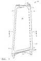
- FIG. 1is a side view of an outlet guide vane constructed in accordance with the present invention
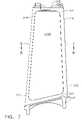
- FIG. 2is a side view of the outlet guide vane of FIG. 1 with a cover removed therefrom;
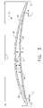
- FIG. 3is a cross-sectional view taken along lines 3 — 3 of FIG. 1 ;
- FIG. 4is a side view of an outlet guide vane constructed according to an alternate embodiment of the invention.
- FIG. 5is a cross-sectional view taken along lines 5 — 5 of FIG. 4 ;
- FIG. 6is an enlarged view of a portion of FIG. 3 .
- FIG. 7is a side view of an outlet guide vane constructed according to another alternate embodiment of the invention.
- FIG. 8is a cross-sectional view taken along lines 8 — 8 of FIG. 7 ;
- FIG. 9is a side view of an outlet guide vane constructed according to another alternate embodiment of the invention.
- FIG. 10is a cross-sectional view taken along lines 10 — 10 of FIG. 9 — 9 .
- FIGS. 1–3depict an exemplary fan outlet guide vane 10 for a gas turbine engine.
- the present inventionis equally applicable to the construction of other types of hollow components, such as rotating turbine blades, frame struts, and the like.
- the outlet guide vane 10comprises an airfoil 12 having a leading edge 14 , a trailing edge 16 , a tip 18 , a root 19 , a convex suction side 20 , and a concave pressure side 22 .
- An arcuate inner platform 24is attached to the root 19 of the airfoil 12 .
- the illustrated airfoil 12has an overall thickness T of about 2.54 cm (1 in.) and a chord length C of about 24 cm (9.5 in.)
- the airfoil 12is assembled from a body 26 and a cover 28 .
- the body 26 and the cover 28are both made from a material with suitable strength and weight characteristics for the intended application.
- One suitable alloyis a 7000 series aluminum alloy, in particular a 7075 aluminum alloy.
- the body 26is a unitary component which may be produced by forging. It includes a recessed pocket 30 (see FIG. 2 ) formed in its pressure side 22 to reduce the weight of the airfoil 12 . It could also be formed in the suction side 20 .
- the ledge 32has a leading edge portion 34 , a trailing edge portion 36 , a tip portion 38 , and a root portion 40 .
- This ledge 32has an average width “W” which is selected to be as narrow as possible to save weight and material, while still leaving enough material for a full penetration weld through the cover 28 .
- the width Wis less than about 1.27 cm (0.5 in.) and is preferably about 0.89 cm (0.35 in.)
- a filler material of a known typemay be placed in the pocket 30 and bonded to the body 26 and/or the cover 28 , for example with an adhesive. Any filler material which will help restrain the relatively flexible cover 28 against vibration and/or stiffen the airfoil 12 may be used.
- suitable filler materialsinclude metallic honeycomb structures, epoxy with microballoons disposed therein, polyurethane foam, and nanostructures.
- the cover 28is a unitary component including inner and outer surfaces 42 and 44 which fits down into the pocket 30 so that the outer surface 44 is substantially flush with the pressure side 22 of the airfoil 12 .
- the outer surface 44 of the cover 28forms a portion of the pressure side 22 of the airfoil 12 .
- the cover 28In plan view, the cover 28 it is generally rectangular with radiused corners. It serves only as an aerodynamic element and may have a relatively small thickness t, for example approximately 2 mm (0.08 in.).
- the periphery of the cover 28is fitted to the periphery of the pocket 30 with a small lateral tolerance “L”, for example about 0.127 mm (0.005 in.)
- FIGS. 4 and 5illustrate an alternative airfoil 112 .
- the airfoil 112is substantially similar to the airfoil 12 described above and is constructed from a body 126 and a cover 128 .
- the airfoil 112includes a leading edge 114 , a trailing edge 116 , a tip 118 , a root 119 , a convex suction side 120 , and a concave pressure side 122 .
- a recessed pocket 130is formed in the pressure side 122 to reduce the weight of the airfoil 112 , and is sealed off by the cover 128 .
- the pocket 130could also be formed in the suction side 120 .
- the body 126includes a plurality of upstanding, spaced-apart ribs 133 disposed in the pocket 130 which extend in the radial direction (i.e. from the root 119 to the tip 118 ).
- the ribs 133serve both to stiffen the airfoil 112 itself, and to restrain the relatively flexible cover 28 against undesirable fatigue and stresses caused by vibrations during engine operation, i.e. 1/rev/blade excitations.
- the cover 28is joined to the body 26 using a friction stir welding process.
- the welding processis carried out using friction stir welding machinery and fixtures of a known type (not shown).
- a cylindrical, shouldered, wear-resistant pin “P” having a tip “R”is rotated and forced against the joint line between the cover 28 and the body 26 .
- the friction between the pin P and the airfoil 12causes the material to soften and flow without melting.
- friction stir weldingis a type of solid state bond.
- the pin Phas a shoulder diameter “D” of about 10.7 mm (0.420 in.), and the tip R has a length “l” of about 2.8 mm (0.110 in.) from the shoulder to its distal end and tapers from a diameter “d 1 ” of about 10.7 mm (0.420 in.) in diameter near the shoulder to a diameter “d 2 ” of about 3.2 mm (0.125 in.) diameter at its distal end, and has a left-hand thread formed thereon.
- the following exemplary parametershave been found to produce an acceptable friction stir welded bond: Pin speed about 700 to about 900 RPM, and preferably about 800 RPM; traversing speed about 10 cm/min. (4 in/min.) to about 15.2 cm/min.
- the pin Pis traversed along the periphery of the cover 28 , straddling the cover and the surface of the body 26 , leaving the cover 28 and body 26 bonded together behind it. If an airfoil 112 having ribs 133 is used, the cover 128 is also friction stir welded to the ribs 133 as well, by traversing the pin “P” over the cover 128 along the rib locations. This process causes very little distortion compared to other forms of welding.
- the completed weldleaves a smooth surface finish in the joint area which requires minimal processing to result in an acceptable finished product.
- the friction stir weld processcan be accomplished with a minimum of distortion which facilitates simplification of post weld heat treatment, if necessary.
- friction stir weldingreduces bond integrity variability, significantly increases bond strength, facilitates further weight reductions through reduction of material overlaps, and provides a metallurgically sound seal to prevent contamination of the pocket 30 from the surrounding environment.
- FIGS. 7 and 8illustrate an alternative airfoil 212 .
- the airfoil 212is substantially similar to the airfoil 12 described above and is constructed from a body 226 and covers 228 a , 228 b .
- the airfoil 212includes a leading edge 214 , a trailing edge 216 , a tip 218 , a root 219 , a convex suction side 220 , and a concave pressure side 222 .
- Recessed first and second pockets 230 a , 230 bare formed in the pressure side 222 and suction side 220 respectively to reduce the weight of the airfoil 212 , and are sealed off by covers 228 a and 228 b .
- the body 226may include a plurality of upstanding, spaced-apart ribs (not shown) disposed in the pockets 230 a and 230 b , similar to ribs 33 described above, or a filler material (not shown) as described above.
- FIGS. 9 and 10illustrate another alternative airfoil 312 .
- the airfoil 312includes a leading edge 314 , a trailing edge 316 , a tip 318 , a root 319 , a convex suction side 320 , and a concave pressure side 322 .
- the airfoil 312is built up from individual components including a pressure side wall 324 , a suction side wall 326 , a leading edge spacer 328 , a trailing edge spacer 330 , and a plurality of internal spacers 332 .
- the internal spacers 332 in the illustrated exampleare rectangular, spanwise ribs. However, the internal spacers 332 could comprise an array of pins or other similar elements.
- the individual componentsmay be relatively simple, inexpensive structural elements.
- the pressure and suction side walls 324 and 326may be aluminum sheet material
- the leading and trailing edge spacers 328 and 330could be aluminum extrusions
- the internal spacers 332could be cast, forged, or extruded from aluminum.
- Other arrangements of built-up componentsare possible.
- the pressure side wall 324 , suction side wall 326 , leading edge spacer 328 , trailing edge spacer 330 , and internal spacers 332are retained in the appropriate positions using suitable tooling of a known type (not shown).
- the componentsare then joined by friction stir welding as described above.
- friction stir weldsmay be located as indicated by the exemplary arrows “F” in FIG. 10 .
- several overlapping adjacent weldsmay be made between the pressure and suction side walls 324 and 326 and the leading and trailing edge spacers 328 and 330 .
- the suction and pressure side walls 324 and 326extend past the leading and trailing edge spacers 328 and 330 to merge with each other at the leading and trailing edges 314 And 316 , respectively.
- the pressure and suction side walls 324 and 326could stop short of the leading and trailing edges in the chordwise direction, in which case the leading and trailing edge spacers 328 and 330 would define the leading and trailing edges of the airfoil 312 .
- the airfoil 312may be machined to form its final contours.
Landscapes
- Engineering & Computer Science (AREA)
- Mechanical Engineering (AREA)
- Architecture (AREA)
- General Engineering & Computer Science (AREA)
- Pressure Welding/Diffusion-Bonding (AREA)
- Turbine Rotor Nozzle Sealing (AREA)
- Structures Of Non-Positive Displacement Pumps (AREA)
Abstract
Description
This invention relates generally to hollow components for gas turbine engines and more particularly to hollow airfoils constructed by friction stir welding.
Aluminum forgings in various alloy compositions are commonly used for gas turbine engine components, for example non-rotating airfoils in the fan and compressor. Such airfoils often have a hollow cross-section to minimize their weight. The alloys of choice, e.g. most 2000- and 7000-series aluminum alloys, may be difficult or impossible to join by conventional fusion welding techniques.
Therefore, prior art methods for producing hollow airfoils involve gun drilling to remove core material, or pocket milling followed by adhesive bonding of a cover sheet over the milled pocket. The pocket may or may not be filled with honeycomb material, and may or may not incorporate stiffener ribs for improved load carrying capabilities and/or fatigue resistance.
Gun drilling is a tedious and inefficient method for removing the maximum core material to optimize weight reduction. On the other hand, pocket milling followed by adhesive bonding of a cover has the disadvantage of excessive adhesive bond quality variability, tedious preparation and processing for adhesive bonding success, excessive lap joint widths to obtain adequate adhesive bond strength, and inability to reliably seal the internal pocket from the external environment resulting in excessive susceptibility to undetected internal corrosion and/or stress corrosion cracking over time.
Accordingly, there is a need for an efficient method for producing sealed hollow components with reliable bond quality.
The above-mentioned need is met by the present invention, which according to one aspect provides a hollow airfoil including a metallic body having opposed pressure and suction sides, a root, a tip, and spaced-apart leading and trailing edges. The body has a recessed pocket formed in a selected one of the pressure and suction sides. A metallic cover having an outer peripheral edge, an inner surface, and an outer surface which defines at least a portion of the selected side is attached to the body by a solid state bond.
According to another aspect of the invention, a method of making a hollow airfoil includes providing an airfoil-shaped body having spaced-apart leading and trailing edges, spaced-apart pressure and suction sides, a root, and a tip. A selected one of the pressure and suction sides has a pocket formed therein. A cover has with a perimeter matching the perimeter of the pocket, and an outer surface defining at least a portion of the selected one of the pressure or suction sides. The cover is placed in the pocket and joined to the body by friction stir welding.
According to another aspect of the invention, a method of making a hollow component for gas turbine engine includes providing a body having spaced-apart first and second sides, the first side having recessed pocket formed therein, and providing a cover having inner and outer surfaces, the outer surface of the cover conforming to the shape of the first side of the body. The cover is placed in the pocket and is attached to the body by friction stir welding.
According to another aspect of the invention, a hollow airfoil has opposed pressure and suction sides, a root, a tip, and spaced-apart leading and trailing edges,the airfoil includes a metallic pressure side wall extending from the leading edge to the trailing edge; a metallic suction side wall extending from the leading edge to the trailing edge, the suction side wall being disposed in spaced-apart relation to the pressure side wall; a metallic leading edge spacer extending from the root to said tip, and disposed between the pressure and suction side walls; and a metallic trailing edge spacer extending from the root to the tip and disposed between the pressure and suction side walls. The pressure side wall and the suction side wall are attached to the leading and trailing edge spacers by a plurality of solid state bonds.
The invention may be best understood by reference to the following description taken in conjunction with the accompanying drawing figures in which:
Referring to the drawings wherein identical reference numerals denote the same elements throughout the various views,FIGS. 1–3 depict an exemplary fanoutlet guide vane 10 for a gas turbine engine. The present invention is equally applicable to the construction of other types of hollow components, such as rotating turbine blades, frame struts, and the like. Theoutlet guide vane 10 comprises anairfoil 12 having a leadingedge 14, atrailing edge 16, atip 18, aroot 19, aconvex suction side 20, and aconcave pressure side 22. An arcuateinner platform 24 is attached to theroot 19 of theairfoil 12.
The illustratedairfoil 12 has an overall thickness T of about 2.54 cm (1 in.) and a chord length C of about 24 cm (9.5 in.) Theairfoil 12 is assembled from abody 26 and acover 28. Thebody 26 and thecover 28 are both made from a material with suitable strength and weight characteristics for the intended application. One suitable alloy is a 7000 series aluminum alloy, in particular a 7075 aluminum alloy. Thebody 26 is a unitary component which may be produced by forging. It includes a recessed pocket30 (seeFIG. 2 ) formed in itspressure side 22 to reduce the weight of theairfoil 12. It could also be formed in thesuction side 20. There is acontinuous ledge 32 disposed around the periphery of thepocket 30 that the periphery of thecover 28 is welded to. Theledge 32 has a leadingedge portion 34, atrailing edge portion 36, atip portion 38, and aroot portion 40. Thisledge 32 has an average width “W” which is selected to be as narrow as possible to save weight and material, while still leaving enough material for a full penetration weld through thecover 28. In the illustrated example, the width W is less than about 1.27 cm (0.5 in.) and is preferably about 0.89 cm (0.35 in.) Depending on the particular application, a filler material of a known type (not shown) may be placed in thepocket 30 and bonded to thebody 26 and/or thecover 28, for example with an adhesive. Any filler material which will help restrain the relativelyflexible cover 28 against vibration and/or stiffen theairfoil 12 may be used. Examples of suitable filler materials include metallic honeycomb structures, epoxy with microballoons disposed therein, polyurethane foam, and nanostructures.
Thecover 28 is a unitary component including inner andouter surfaces pocket 30 so that theouter surface 44 is substantially flush with thepressure side 22 of theairfoil 12. Theouter surface 44 of thecover 28 forms a portion of thepressure side 22 of theairfoil 12. In plan view, thecover 28 it is generally rectangular with radiused corners. It serves only as an aerodynamic element and may have a relatively small thickness t, for example approximately 2 mm (0.08 in.). To provide an acceptable weld joint, the periphery of thecover 28 is fitted to the periphery of thepocket 30 with a small lateral tolerance “L”, for example about 0.127 mm (0.005 in.)
Thecover 28 is joined to thebody 26 using a friction stir welding process. The welding process is carried out using friction stir welding machinery and fixtures of a known type (not shown). As shown inFIG. 6 , a cylindrical, shouldered, wear-resistant pin “P” having a tip “R” is rotated and forced against the joint line between thecover 28 and thebody 26. The friction between the pin P and theairfoil 12 causes the material to soften and flow without melting. Thus, friction stir welding is a type of solid state bond. In the illustrated example the pin P has a shoulder diameter “D” of about 10.7 mm (0.420 in.), and the tip R has a length “l” of about 2.8 mm (0.110 in.) from the shoulder to its distal end and tapers from a diameter “d1” of about 10.7 mm (0.420 in.) in diameter near the shoulder to a diameter “d2” of about 3.2 mm (0.125 in.) diameter at its distal end, and has a left-hand thread formed thereon. The following exemplary parameters have been found to produce an acceptable friction stir welded bond: Pin speed about 700 to about 900 RPM, and preferably about 800 RPM; traversing speed about 10 cm/min. (4 in/min.) to about 15.2 cm/min. (6 in/min.), and preferably about 5 in/min.; and force on the pin P about 499 kg (1100 lbs.) to about 635 kg (1400 lbs.), and preferably about 590 kg (1300 lbs.) The pin P is traversed along the periphery of thecover 28, straddling the cover and the surface of thebody 26, leaving thecover 28 andbody 26 bonded together behind it. If anairfoil 112 havingribs 133 is used, thecover 128 is also friction stir welded to theribs 133 as well, by traversing the pin “P” over thecover 128 along the rib locations. This process causes very little distortion compared to other forms of welding. The completed weld leaves a smooth surface finish in the joint area which requires minimal processing to result in an acceptable finished product. Typically, there may be a recessed zone about 0.05 mm (0.002 in.) deep along the weld path. If necessary, a minor polishing operation may be performed to smooth out this zone. Furthermore, the friction stir weld process can be accomplished with a minimum of distortion which facilitates simplification of post weld heat treatment, if necessary. Compared to adhesive bonding, friction stir welding reduces bond integrity variability, significantly increases bond strength, facilitates further weight reductions through reduction of material overlaps, and provides a metallurgically sound seal to prevent contamination of thepocket 30 from the surrounding environment.
To assemble theairfoil 312, thepressure side wall 324,suction side wall 326, leadingedge spacer 328, trailingedge spacer 330, andinternal spacers 332 are retained in the appropriate positions using suitable tooling of a known type (not shown). The components are then joined by friction stir welding as described above. For example, friction stir welds may be located as indicated by the exemplary arrows “F” inFIG. 10 . To ensure the security of the bonds, several overlapping adjacent welds may be made between the pressure andsuction side walls edge spacers pressure side walls edge spacers edges 314 And316, respectively. However, if desired the pressure andsuction side walls edge spacers airfoil 312. After the welding operation in complete, theairfoil 312 may be machined to form its final contours.
The foregoing has described a hollow airfoil structure having a cover attached by friction stir welding, and a process for making such an airfoil. While specific embodiments of the present invention have been described, it will be apparent to those skilled in the art that various modifications thereto can be made without departing from the spirit and scope of the invention. Accordingly, the foregoing description of the preferred embodiment of the invention and the best mode for practicing the invention are provided for the purpose of illustration only and not for the purpose of limitation, the invention being defined by the claims.
Claims (33)
1. A hollow airfoil, comprising:
a metallic body having opposed pressure and suction sides, a root, a tip, and spaced-apart leading and trailing edges, said body having a recessed first pocket formed in a selected one of said pressure and suction sides;
a filler material disposed in said first pocket; and
a first metallic cover having an outer peripheral edge, an inner surface, and an outer surface, said outer surface defining at least a portion of said selected one of said pressure or suction sides, wherein said first cover is attached to said body by a solid state bond.
2. The hollow airfoil ofclaim 1 wherein said first pocket includes at least one upstanding rib which extends in a direction from said root to said tip, and said first cover is attached to said rib by a solid state bond.
3. The hollow airfoil ofclaim 1 wherein said body includes a recessed ledge extending around the periphery of said first pocket which is adapted for receiving said first cover such that said outer surface of said first cover fits substantially flush with said selected one of said pressure and suction sides of said airfoil.
4. The hollow airfoil ofclaim 1 wherein said cover and said body comprise a 7000 series aluminum alloy.
5. The hollow airfoil ofclaim 4 wherein said cover and said body comprise a 7075 aluminum alloy.
6. The hollow airfoil ofclaim 1 wherein said airfoil forms part of a fan outlet guide vane.
7. The hollow airfoil ofclaim 1 wherein said solid state bond is a friction stir weld.
8. The hollow airfoil ofclaim 1 wherein said filler material is a honeycomb structure.
9. The hollow airfoil ofclaim 1 wherein said filler material is bonded to at least one of said first pocket and said first cover with an adhesive.
10. The hollow airfoil ofclaim 1 further comprising:
a second recessed pocket formed in the other one of said pressure and suction sides; and
a second metallic cover having an outer peripheral edge, as inner surface, and an outer surface, said outer surface defining at least a portion of said other one of said pressure or suction sides, wherein said second cover is attached to said body by a solid state bond.
11. The hollow airfoil ofclaim 10 wherein said body includes a recessed ledge extending around the periphery of said second pocket which is adapted for receiving said second cover such that said outer surface of said second cover fits substantially flush with said other one of said pressure and suction sides of said airfoil.
12. The hollow airfoil ofclaim 10 further comprising a filler material disposed in said second pocket.
13. The hollow airfoil ofclaim 12 wherein said filler material is a honeycomb structure.
14. The hollow airfoil ofclaim 12 wherein said filler material is bonded to at least one of said second pocket and said second cover with an adhesive.
15. A method of making a hollow airfoil, comprising:
providing an airfoil-shaped body having spaced-apart leading and trailing edges, spaced-apart pressure and suction sides, a root, and a tip, a selected one of said pressure and suction sides having a first pocket formed therein;
providing a first cover with a perimeter matching the perimeter of said first pocket, and an outer surface defining at least a portion of said selected one of said pressure or said suction sides;
placing a filler material in said first pocket;
placing said cover in said first pocket; and
joining said first cover to said body by friction stir welding such that said first pocket is sealed from a surrounding environment.
16. The method ofclaim 15 wherein the step of placing said first cover in said first pocket further comprises placing said first cover against a recessed ledge formed in said body which extends around the periphery of said first pocket, the depth of said first pocket being selected to position said first cover such that said outer surface of said first cover fits substantially flush with said selected one of said pressure and suction sides of said airfoil.
17. The method ofclaim 15 wherein said filler material is a honeycomb structure.
18. The method ofclaim 15 further comprising bonding said filler material to at least one of said first pocket and said first cover with an adhesive.
19. The method ofclaim 15 further comprising:
forming a second recessed pocket in the other one of said pressure and suction sides of said body;
providing a second cover with a perimeter matching the perimeter of said second pocket, and an outer surface defining at least a portion of the other one of said pressure or said suction sides;
placing said cover in said second pocket; and
joining said second cover to said body by friction stir welding such that said second pocket is sealed from a surrounding environment.
20. The method of19 further comprising placing a filler material in said second pocket.
21. The method ofclaim 20 wherein said filler material is a honeycomb structure.
22. The method ofclaim 20 further comprising bonding said filler material bonded to at least one of said second pocket and said second cover with an adhesive.
23. The method ofclaim 15 wherein said first pocket includes at least one upstanding rib which extends in a direction from said root to said tip, and said first cover is attached to said rib by friction stir welding.
24. The method ofclaim 15 wherein said first cover and said body comprise a 7000 series aluminum alloy.
25. The method ofclaim 24 wherein said first cover and said body comprise a 7075 aluminum alloy.
26. The method ofclaim 15 wherein said airfoil forms part of a fan outlet guide vane.
27. A hollow airfoil having opposed pressure and suction sides, a root, a tip, and spaced-apart leading and trailing edges, said airfoil comprising:
a metallic pressure side wall extending from said leading edge to said trailing edge;
a metallic suction side wall extending from said leading edge to said trailing edge, said suction side wall disposed in spaced-apart relation to said pressure side wall;
a metallic leading edge spacer extending from said root to said tip, the leading edge spacer separate from and disposed between said pressure and suction side walls; and
a metallic trailing edge spacer extending from said root to said tip, the trailing edge spacer separate from and disposed between said pressure and suction side walls;
wherein said pressure side wall and said suction side wall are attached to said leading and trailing edge spacers by a plurality of solid state bonds.
28. The hollow airfoil ofclaim 27 further comprising at least one metallic internal spacer disposed between said pressure and suction side walls, said internal spacer being attached to each of said pressure and suction side walls by a solid state bond.
29. The hollow airfoil ofclaim 28 wherein said internal spacer extends from said root to said tip of said airfoil.
30. The hollow airfoil ofclaim 27 wherein said pressure side wall, said suction side wall, said reading edge spacer, and said trailing edge spacer comprise a 7000 series aluminum alloy.
31. The hollow airfoil ofclaim 27 wherein said pressure side wall, said suction side wall, said leading edge spacer, and said trailing edge spacer comprise a 7075 aluminum alloy.
32. The hollow airfoil ofclaim 27 wherein said airfoil forms part of a fan outlet guide vane.
33. The hollow airfoil ofclaim 27 wherein said solid state bond is a friction stir weld.
Priority Applications (3)
| Application Number | Priority Date | Filing Date | Title |
|---|---|---|---|
| US10/846,326US7189064B2 (en) | 2004-05-14 | 2004-05-14 | Friction stir welded hollow airfoils and method therefor |
| EP05252903AEP1596036A1 (en) | 2004-05-14 | 2005-05-11 | Friction stir welded hollow airfoils and method therefor |
| JP2005140766AJP2005325839A (en) | 2004-05-14 | 2005-05-13 | Hollow vane-shaped part joined by friction stirring and method for it |
Applications Claiming Priority (1)
| Application Number | Priority Date | Filing Date | Title |
|---|---|---|---|
| US10/846,326US7189064B2 (en) | 2004-05-14 | 2004-05-14 | Friction stir welded hollow airfoils and method therefor |
Publications (2)
| Publication Number | Publication Date |
|---|---|
| US20050254955A1 US20050254955A1 (en) | 2005-11-17 |
| US7189064B2true US7189064B2 (en) | 2007-03-13 |
Family
ID=34941251
Family Applications (1)
| Application Number | Title | Priority Date | Filing Date |
|---|---|---|---|
| US10/846,326Expired - Fee RelatedUS7189064B2 (en) | 2004-05-14 | 2004-05-14 | Friction stir welded hollow airfoils and method therefor |
Country Status (3)
| Country | Link |
|---|---|
| US (1) | US7189064B2 (en) |
| EP (1) | EP1596036A1 (en) |
| JP (1) | JP2005325839A (en) |
Cited By (60)
| Publication number | Priority date | Publication date | Assignee | Title |
|---|---|---|---|---|
| US20070002686A1 (en)* | 2005-06-30 | 2007-01-04 | Spx Corporation | Mixing impeller and method with top and bottom skin elements |
| US20070154307A1 (en)* | 2006-01-03 | 2007-07-05 | General Electric Company | Apparatus and method for assembling a gas turbine stator |
| US20080253885A1 (en)* | 2007-04-16 | 2008-10-16 | United Technologies Corporation | Gas turbine engine vane |
| US20080308610A1 (en)* | 2007-06-15 | 2008-12-18 | United Technologies Corporation | Hollow structures formed with friction stir welding |
| US20080308197A1 (en)* | 2007-06-15 | 2008-12-18 | United Technologies Corporation | Secondary processing of structures derived from AL-RE-TM alloys |
| US20080311421A1 (en)* | 2007-06-15 | 2008-12-18 | United Technologies Corporation | Friction stir welded structures derived from AL-RE-TM alloys |
| US20100068550A1 (en)* | 2007-06-15 | 2010-03-18 | United Technologies Corporation | Hollow structures formed with friction stir welding |
| US20100155016A1 (en)* | 2008-12-23 | 2010-06-24 | General Electric Company | Combined surface cooler and acoustic absorber for turbomachines |
| DE102009022181A1 (en)* | 2009-05-20 | 2010-11-25 | W & S Management Gmbh & Co. Kg | fan blade |
| US20110268562A1 (en)* | 2010-04-30 | 2011-11-03 | General Electric Company | Gas turbine engine airfoil integrated heat exchanger |
| US20120020805A1 (en)* | 2010-07-26 | 2012-01-26 | Suciu Gabriel L | Reverse cavity blade for a gas turbine engine |
| US20120237351A1 (en)* | 2011-03-17 | 2012-09-20 | Weisse Michael A | Retention for bonded hollow fan blade cover |
| US20130064661A1 (en)* | 2011-09-08 | 2013-03-14 | Rolls-Royce Plc | Aerofoil assembly |
| WO2013103663A1 (en)* | 2012-01-04 | 2013-07-11 | United Technologies Corporation | Aluminum fan blade construction with welded cover |
| WO2014042975A1 (en)* | 2012-09-12 | 2014-03-20 | United Technologies Corporation | Hollow fan blade with honeycomb filler |
| WO2014051670A1 (en)* | 2012-09-25 | 2014-04-03 | United Technologies Corporation | Airfoil array with airfoils that differ in geometry according to geometry classes |
| US20140170435A1 (en)* | 2012-12-17 | 2014-06-19 | United Technologies Corporation | Hollow airfoil with composite cover and foam filler |
| WO2014137415A1 (en)* | 2013-03-08 | 2014-09-12 | United Technologies Corporation | Covers for cavities in aircraft fan blades |
| US9004873B2 (en) | 2010-12-27 | 2015-04-14 | Rolls-Royce Corporation | Airfoil, turbomachine and gas turbine engine |
| US20150226068A1 (en)* | 2012-10-30 | 2015-08-13 | PIETRO ROSA T.B.M. S.r.I. | Manufacturing process of a lightened turbomachine blade |
| US20150252679A1 (en)* | 2012-10-01 | 2015-09-10 | United Technologies Corporation | Static guide vane with internal hollow channels |
| US20150267541A1 (en)* | 2014-01-16 | 2015-09-24 | United Technologies Corporation | Fan Blade Composite Cover with Tapered Edges |
| US20160146015A1 (en)* | 2014-11-24 | 2016-05-26 | Rolls-Royce Plc | Fluidfoil |
| US20160215789A1 (en)* | 2013-09-24 | 2016-07-28 | United Technologies Corporation | Fan blade assembly |
| US20160258297A1 (en)* | 2015-03-05 | 2016-09-08 | Techspace Aero S.A. | Composite Compressor Blade for an Axial-Flow Turbomachine |
| US20160305443A1 (en)* | 2013-12-16 | 2016-10-20 | United Technologies Corporation | Hollow fan blade with stir welded cover support |
| US9624783B2 (en) | 2013-02-28 | 2017-04-18 | Pietro Rosa T.B.M. S.R.L. | Turbomachine blade and relative production method |
| US20170292531A1 (en)* | 2016-04-06 | 2017-10-12 | Rolls-Royce North American Technologies, Inc. | Fluid cooling system integrated with outlet guide vane |
| US9816382B2 (en) | 2013-02-28 | 2017-11-14 | Pietro Rosa T.B.M. S.R.L. | Turbomachine blade and relative production method |
| US20180017075A1 (en)* | 2016-07-13 | 2018-01-18 | Rolls-Royce Corporation | Airfoil with stress-reducing fillet adapted for use in a gas turbine engine |
| US20180038386A1 (en)* | 2016-08-08 | 2018-02-08 | United Technologies Corporation | Fan blade with composite cover |
| US9909448B2 (en) | 2015-04-15 | 2018-03-06 | General Electric Company | Gas turbine engine component with integrated heat pipe |
| US10145245B2 (en) | 2013-09-24 | 2018-12-04 | United Technologies Corporation | Bonded multi-piece gas turbine engine component |
| US20190040744A1 (en)* | 2017-08-07 | 2019-02-07 | United Technologies Corporation | Power beam welded cavity-back titanium hollow fan blade |
| US10215027B2 (en) | 2012-01-04 | 2019-02-26 | United Technologies Corporation | Aluminum fan blade construction with welded cover |
| US10329919B2 (en) | 2017-04-07 | 2019-06-25 | United Technologies Corporation | Airfoil structure and method of manufacture |
| US10356945B2 (en) | 2015-01-08 | 2019-07-16 | General Electric Company | System and method for thermal management using vapor chamber |
| US10365047B2 (en) | 2016-06-21 | 2019-07-30 | Ge Aviation Systems Llc | Electronics cooling with multi-phase heat exchange and heat spreader |
| US10458249B2 (en) | 2013-11-08 | 2019-10-29 | United Technologies Corporation | Bonded multi-piece gas turbine engine component |
| US20190381608A1 (en)* | 2018-06-14 | 2019-12-19 | United Technologies Corporation | Installation of laser vent holes into vertical walls of cavity-back airfoils |
| US10660236B2 (en) | 2014-04-08 | 2020-05-19 | General Electric Company | Systems and methods for using additive manufacturing for thermal management |
| US20200215642A1 (en)* | 2019-01-08 | 2020-07-09 | United Technologies Corporation | Hollow airfoil with catenary profiles |
| US10793943B2 (en) | 2018-03-15 | 2020-10-06 | Raytheon Technologies Corporation | Method of producing a gas turbine engine component |
| US10828718B2 (en)* | 2018-06-14 | 2020-11-10 | Raytheon Technologies Corporation | Installation of waterjet vent holes into vertical walls of cavity-back airfoils |
| US11174737B2 (en) | 2019-06-12 | 2021-11-16 | Raytheon Technologies Corporation | Airfoil with cover for gas turbine engine |
| US11236619B2 (en) | 2019-05-07 | 2022-02-01 | Raytheon Technologies Corporation | Multi-cover gas turbine engine component |
| US11248477B2 (en) | 2019-08-02 | 2022-02-15 | Raytheon Technologies Corporation | Hybridized airfoil for a gas turbine engine |
| US11260953B2 (en) | 2019-11-15 | 2022-03-01 | General Electric Company | System and method for cooling a leading edge of a high speed vehicle |
| US11260976B2 (en) | 2019-11-15 | 2022-03-01 | General Electric Company | System for reducing thermal stresses in a leading edge of a high speed vehicle |
| US11267551B2 (en) | 2019-11-15 | 2022-03-08 | General Electric Company | System and method for cooling a leading edge of a high speed vehicle |
| US11352120B2 (en) | 2019-11-15 | 2022-06-07 | General Electric Company | System and method for cooling a leading edge of a high speed vehicle |
| US11407488B2 (en) | 2020-12-14 | 2022-08-09 | General Electric Company | System and method for cooling a leading edge of a high speed vehicle |
| US11427330B2 (en) | 2019-11-15 | 2022-08-30 | General Electric Company | System and method for cooling a leading edge of a high speed vehicle |
| US11499566B2 (en)* | 2018-08-30 | 2022-11-15 | Raytheon Technologies Corporation | Fan blade having closed metal sheath |
| US11577817B2 (en) | 2021-02-11 | 2023-02-14 | General Electric Company | System and method for cooling a leading edge of a high speed vehicle |
| US11745847B2 (en) | 2020-12-08 | 2023-09-05 | General Electric Company | System and method for cooling a leading edge of a high speed vehicle |
| US11867084B1 (en) | 2022-12-20 | 2024-01-09 | Rtx Corporation | Hollow airfoil construction using cover subassembly |
| US12040690B2 (en) | 2020-08-31 | 2024-07-16 | General Electric Company | Cooling a stator housing of an electric machine |
| FR3153551A1 (en)* | 2023-09-28 | 2025-04-04 | Safran Aircraft Engines | Forged part for manufacturing a structural arm of an intermediate casing of a dual-flow turbojet engine and method of manufacturing such a structural arm |
| US20250243766A1 (en)* | 2024-01-31 | 2025-07-31 | Honeywell International Inc. | Polymer-metal composite stator vanes and methods for manufacturing the same |
Families Citing this family (73)
| Publication number | Priority date | Publication date | Assignee | Title |
|---|---|---|---|---|
| US7487901B2 (en)* | 2004-07-29 | 2009-02-10 | The Boeing Company | Friction stir welding of joints with shims |
| US8632850B2 (en) | 2005-09-26 | 2014-01-21 | Schultz-Creehan Holdings, Inc. | Friction fabrication tools |
| US9511446B2 (en) | 2014-12-17 | 2016-12-06 | Aeroprobe Corporation | In-situ interlocking of metals using additive friction stir processing |
| US9266191B2 (en) | 2013-12-18 | 2016-02-23 | Aeroprobe Corporation | Fabrication of monolithic stiffening ribs on metallic sheets |
| US9511445B2 (en)* | 2014-12-17 | 2016-12-06 | Aeroprobe Corporation | Solid state joining using additive friction stir processing |
| GB0613441D0 (en)* | 2006-07-06 | 2006-08-16 | Rolls Royce Plc | Blades |
| US20080072569A1 (en)* | 2006-09-27 | 2008-03-27 | Thomas Ory Moniz | Guide vane and method of fabricating the same |
| DE102006061916A1 (en) | 2006-12-21 | 2008-06-26 | Rolls-Royce Deutschland Ltd & Co Kg | Fan blade for a gas turbine engine |
| US20080159851A1 (en)* | 2006-12-29 | 2008-07-03 | Thomas Ory Moniz | Guide Vane and Method of Fabricating the Same |
| US20080159856A1 (en)* | 2006-12-29 | 2008-07-03 | Thomas Ory Moniz | Guide vane and method of fabricating the same |
| US20080230584A1 (en)* | 2007-03-19 | 2008-09-25 | The Boeing Company | Method for Manufacturing a Workpiece by Friction Welding to Reduce the Occurrence of Abnormal Grain Growth |
| US7607287B2 (en)* | 2007-05-29 | 2009-10-27 | United Technologies Corporation | Airfoil acoustic impedance control |
| RU2455138C2 (en)* | 2007-09-19 | 2012-07-10 | Барнс Груп Инк. | Diffusion joint |
| FR2921973B1 (en)* | 2007-10-04 | 2011-04-29 | Snecma | INTERMEDIATE CASING OF TURBOJET AND TURBOREACTOR |
| JP2009107461A (en)* | 2007-10-30 | 2009-05-21 | Kinki Sharyo Co Ltd | Outer plate structure |
| US8511983B2 (en)* | 2008-02-19 | 2013-08-20 | United Technologies Corporation | LPC exit guide vane and assembly |
| US8333552B2 (en)* | 2008-06-20 | 2012-12-18 | General Electric Company | Combined acoustic absorber and heat exchanging outlet guide vanes |
| US20100104446A1 (en)* | 2008-10-28 | 2010-04-29 | General Electric Company | Fabricated hybrid turbine blade |
| JP2010190128A (en)* | 2009-02-18 | 2010-09-02 | Toshiba Corp | Method for preventing erosion of turbine blade, and turbine blade |
| US8177513B2 (en) | 2009-02-18 | 2012-05-15 | General Electric Company | Method and apparatus for a structural outlet guide vane |
| US8172541B2 (en)* | 2009-02-27 | 2012-05-08 | General Electric Company | Internally-damped airfoil and method therefor |
| US8240999B2 (en)* | 2009-03-31 | 2012-08-14 | United Technologies Corporation | Internally supported airfoil and method for internally supporting a hollow airfoil during manufacturing |
| US8585368B2 (en) | 2009-04-16 | 2013-11-19 | United Technologies Corporation | Hybrid structure airfoil |
| US8083489B2 (en)* | 2009-04-16 | 2011-12-27 | United Technologies Corporation | Hybrid structure fan blade |
| CA2669000A1 (en)* | 2009-06-18 | 2010-12-18 | Garold Toews | A kit for modifying a strut of an aircraft with an aerodynamic cover |
| DE102009053450A1 (en)* | 2009-11-17 | 2011-05-19 | Werner Lange | Classifier for cleaning a pulp suspension |
| RU2012127372A (en)* | 2009-11-30 | 2014-01-10 | Снекма | METHOD FOR PERFORMING METAL AMPLIFICATION ELEMENT OF TURBO MACHINE BLADES |
| FR2953430B1 (en)* | 2009-12-03 | 2012-03-02 | Snecma | PROCESS FOR MAKING A TURBOMACHINE METAL TURBINE REINFORCEMENT |
| US9650897B2 (en)* | 2010-02-26 | 2017-05-16 | United Technologies Corporation | Hybrid metal fan blade |
| EP2366871B1 (en)* | 2010-03-17 | 2016-05-11 | General Electric Company | Method and apparatus for a structural outlet guide vane |
| JP5647426B2 (en)* | 2010-03-17 | 2014-12-24 | ゼネラル・エレクトリック・カンパニイ | Method and apparatus for structural exit guide vanes |
| JP5411120B2 (en)* | 2010-12-27 | 2014-02-12 | 株式会社日立製作所 | Titanium alloy turbine blade |
| CN102094847B (en)* | 2010-12-30 | 2012-10-24 | 北京理工大学 | Fused design method for turbine machinery blades and end wall |
| FR2978196B1 (en)* | 2011-07-20 | 2016-12-09 | Snecma | TURBOMACHINE AUB COMPRISING A PLATE REPORTED ON A MAIN PART |
| US20130082088A1 (en)* | 2011-09-30 | 2013-04-04 | General Electric Company | Method and apparatus for repairing a component |
| US9233414B2 (en)* | 2012-01-31 | 2016-01-12 | United Technologies Corporation | Aluminum airfoil |
| US10982551B1 (en) | 2012-09-14 | 2021-04-20 | Raytheon Technologies Corporation | Turbomachine blade |
| US20140241897A1 (en)* | 2012-09-25 | 2014-08-28 | United Technologies Corporation | Aluminum brazing of hollow titanium fan blades |
| US9441496B2 (en)* | 2012-09-26 | 2016-09-13 | United Technologies Corporation | Structural guide vane internal topology |
| EP2920072B8 (en)* | 2012-11-19 | 2020-11-11 | Raytheon Technologies Corporation | Fan blade and corresponding method of manufacturing |
| EP2735706B8 (en)* | 2012-11-21 | 2016-12-07 | Safran Aero Booster S.A. | Vane diffuser of an axial turbomachine compressor and method for manufacturing same |
| GB201302262D0 (en)* | 2013-02-08 | 2013-03-27 | Rolls Royce Plc | Manufacture of hollow aerofoil |
| US20140286785A1 (en)* | 2013-03-08 | 2014-09-25 | General Electric Company | Method of producing a hollow airfoil |
| US9957824B2 (en)* | 2013-03-15 | 2018-05-01 | United Technologies Corporation | Vibration damping for structural guide vanes |
| JP6167677B2 (en) | 2013-06-06 | 2017-07-26 | 株式会社Ihi | Wings and fans in fans |
| CN103410777B (en)* | 2013-08-19 | 2016-05-18 | 奥美森智能装备股份有限公司 | Fan blade |
| US10329918B2 (en) | 2013-10-18 | 2019-06-25 | United Technologies Corporation | Multiple piece engine component |
| WO2015102715A2 (en)* | 2013-10-30 | 2015-07-09 | United Technologies Corporation | Fan blade composite ribs |
| US10808718B2 (en) | 2013-10-30 | 2020-10-20 | Raytheon Technologies Corporation | Fan blade composite segments |
| EP3074605B1 (en)* | 2013-11-26 | 2018-12-05 | United Technologies Corporation | Fan blade with segmented fan blade cover |
| CN103790639B (en)* | 2013-12-26 | 2016-11-16 | 北京理工大学 | A method for trimming the leading edge strip of the blade in the end zone of the turbomachine |
| US9804058B2 (en)* | 2014-02-27 | 2017-10-31 | Pratt & Whitney Canada Corp. | Method of facilitating visual detection of a crack in a component of a gas turbine engine |
| US9656761B2 (en)* | 2014-04-30 | 2017-05-23 | The Boeing Company | Lipskin for a nacelle and methods of making the same |
| US9938852B2 (en) | 2014-04-30 | 2018-04-10 | The Boeing Company | Noise attenuating lipskin assembly and methods of assembling the same |
| US9708072B2 (en) | 2014-04-30 | 2017-07-18 | The Boeing Company | Aircraft engine nacelle bulkheads and methods of assembling the same |
| US9604438B2 (en) | 2014-04-30 | 2017-03-28 | The Boeing Company | Methods and apparatus for noise attenuation in an engine nacelle |
| US20160177732A1 (en)* | 2014-07-22 | 2016-06-23 | United Technologies Corporation | Hollow fan blade for a gas turbine engine |
| FR3024750B1 (en)* | 2014-08-06 | 2019-07-12 | Safran Aircraft Engines | AUBE CREUSE COMPOSED OF TWO GLUED PARTS BETWEEN THEM, IN PARTICULAR FOR TURBOMACHINE |
| DE102015203765A1 (en)* | 2015-03-03 | 2016-09-08 | Siemens Aktiengesellschaft | Solid hollow component with sheet metal for creating a cavity |
| FR3034131B1 (en)* | 2015-03-24 | 2017-03-17 | Snecma | STATOR BLADE OF STATOR FOR A TURBOMACHINE |
| GB201506901D0 (en)* | 2015-04-23 | 2015-06-10 | Rolls Royce Plc | Manufacture of a hollow aerofoil |
| CN107849672B (en)* | 2015-09-14 | 2021-03-02 | 三菱动力株式会社 | Method for manufacturing turbine rotor blade |
| EP3153664A1 (en)* | 2015-10-07 | 2017-04-12 | United Technologies Corporation | Aluminum fan blade construction with welded cover |
| US9845728B2 (en)* | 2015-10-15 | 2017-12-19 | Rohr, Inc. | Forming a nacelle inlet for a turbine engine propulsion system |
| US20170198592A1 (en)* | 2016-01-11 | 2017-07-13 | General Electric Company | Methods for mounting a turbine subcomponent to a turbine component |
| GB2551750B (en)* | 2016-06-29 | 2020-03-25 | Rolls Royce Plc | Cavity sealing |
| US11131314B2 (en)* | 2016-09-14 | 2021-09-28 | Raytheon Technologies Corporation | Fan blade with structural spar and integrated leading edge |
| FR3061512B1 (en)* | 2017-01-05 | 2020-10-23 | Safran Aircraft Engines | RADIAL ELEMENT OF TURBOMACHINE STATOR WITH A STRAIGHTENER |
| US11199096B1 (en) | 2017-01-17 | 2021-12-14 | Raytheon Technologies Corporation | Turbomachine blade |
| US11261737B1 (en) | 2017-01-17 | 2022-03-01 | Raytheon Technologies Corporation | Turbomachine blade |
| JP7089034B2 (en) | 2017-10-31 | 2022-06-21 | メルド マニファクチャリング コーポレーション | Solid-state laminated modeling system as well as material composition and structural background |
| US11433990B2 (en) | 2018-07-09 | 2022-09-06 | Rohr, Inc. | Active laminar flow control system with composite panel |
| US10808541B2 (en)* | 2018-12-13 | 2020-10-20 | Raytheon Technologies Corporation | Fan blade for a gas turbine engine |
Citations (17)
| Publication number | Priority date | Publication date | Assignee | Title |
|---|---|---|---|---|
| US1992338A (en)* | 1931-06-05 | 1935-02-26 | Bendix Aviat Corp | Propeller blade and method of making the same |
| US3359936A (en)* | 1966-06-23 | 1967-12-26 | Wilson Shipyard Inc | Hydrofoil |
| US4820117A (en)* | 1987-07-09 | 1989-04-11 | United Technologies Corporation | Crossed I-beam structural strut |
| US5099573A (en) | 1990-06-27 | 1992-03-31 | Compressor Components Textron Inc. | Method of making hollow articles |
| US5469618A (en) | 1993-12-06 | 1995-11-28 | General Electric Company | Method for manufacturing hollow airfoils (two-piece concept) |
| US5655883A (en) | 1995-09-25 | 1997-08-12 | General Electric Company | Hybrid blade for a gas turbine |
| US5725355A (en)* | 1996-12-10 | 1998-03-10 | General Electric Company | Adhesive bonded fan blade |
| US5797182A (en)* | 1995-11-11 | 1998-08-25 | Mtu Motoren- Und Turbinen-Union Muenchen Gmbh | Method for producing rotors with blades |
| EP0867621A1 (en) | 1996-10-14 | 1998-09-30 | Daikin Industries, Limited | Method of manufacturing hollow blade, and hollow blade manufactured by same |
| US20010007634A1 (en) | 1998-05-20 | 2001-07-12 | Beyer James R. | Hollow blade for hydraulic turbine or pump |
| US6450394B1 (en) | 1997-06-20 | 2002-09-17 | Bae Systems Plc | Friction welding metal components |
| US6484924B1 (en)* | 2001-08-14 | 2002-11-26 | The Boeing Company | Method and apparatus for backing up a friction stir weld joint |
| EP1291115A2 (en) | 2001-08-29 | 2003-03-12 | The Boeing Company | Interface preparation for weld joints |
| US6568582B2 (en) | 2001-03-27 | 2003-05-27 | The Boeing Company | Application of friction stir welding to superplastically formed structural assemblies |
| US6676004B1 (en) | 2001-02-13 | 2004-01-13 | Edison Welding Institute, Inc. | Tool for friction stir welding |
| JP2004017097A (en) | 2002-06-17 | 2004-01-22 | Shin Meiwa Ind Co Ltd | Hollow assembly structure, aircraft rotor blade, and method of manufacturing hollow assembly structure |
| EP1462609A1 (en) | 2003-03-28 | 2004-09-29 | Snecma Moteurs | Turbomachine blade with reduced weight and it's production method |
Family Cites Families (7)
| Publication number | Priority date | Publication date | Assignee | Title |
|---|---|---|---|---|
| US1762352A (en)* | 1928-10-09 | 1930-06-10 | Westinghouse Electric & Mfg Co | Turbine blade |
| US2698666A (en)* | 1952-07-01 | 1955-01-04 | Gen Motors Corp | Propeller blade |
| US3695778A (en)* | 1970-09-18 | 1972-10-03 | Trw Inc | Turbine blade |
| JPH10193143A (en)* | 1997-01-17 | 1998-07-28 | Showa Alum Corp | Friction stir welding |
| JPH1147959A (en)* | 1997-07-31 | 1999-02-23 | Mitsubishi Heavy Ind Ltd | Manufacture of outside sheet |
| JP2001047260A (en)* | 1999-08-06 | 2001-02-20 | Mitsubishi Heavy Ind Ltd | Manufacture of member whose form of section varies in londitudinal direction, member made by the manufacture, and airplane made by using the member |
| US6453670B1 (en)* | 2000-12-21 | 2002-09-24 | Delphi Technologies, Inc. | Two-piece stationary seal master cylinder |
- 2004
- 2004-05-14USUS10/846,326patent/US7189064B2/ennot_activeExpired - Fee Related
- 2005
- 2005-05-11EPEP05252903Apatent/EP1596036A1/ennot_activeCeased
- 2005-05-13JPJP2005140766Apatent/JP2005325839A/enactivePending
Patent Citations (18)
| Publication number | Priority date | Publication date | Assignee | Title |
|---|---|---|---|---|
| US1992338A (en)* | 1931-06-05 | 1935-02-26 | Bendix Aviat Corp | Propeller blade and method of making the same |
| US3359936A (en)* | 1966-06-23 | 1967-12-26 | Wilson Shipyard Inc | Hydrofoil |
| US4820117A (en)* | 1987-07-09 | 1989-04-11 | United Technologies Corporation | Crossed I-beam structural strut |
| US5099573A (en) | 1990-06-27 | 1992-03-31 | Compressor Components Textron Inc. | Method of making hollow articles |
| US5469618A (en) | 1993-12-06 | 1995-11-28 | General Electric Company | Method for manufacturing hollow airfoils (two-piece concept) |
| US5655883A (en) | 1995-09-25 | 1997-08-12 | General Electric Company | Hybrid blade for a gas turbine |
| US5797182A (en)* | 1995-11-11 | 1998-08-25 | Mtu Motoren- Und Turbinen-Union Muenchen Gmbh | Method for producing rotors with blades |
| EP0867621A1 (en) | 1996-10-14 | 1998-09-30 | Daikin Industries, Limited | Method of manufacturing hollow blade, and hollow blade manufactured by same |
| US5725355A (en)* | 1996-12-10 | 1998-03-10 | General Electric Company | Adhesive bonded fan blade |
| US6450394B1 (en) | 1997-06-20 | 2002-09-17 | Bae Systems Plc | Friction welding metal components |
| US20010007634A1 (en) | 1998-05-20 | 2001-07-12 | Beyer James R. | Hollow blade for hydraulic turbine or pump |
| US6676004B1 (en) | 2001-02-13 | 2004-01-13 | Edison Welding Institute, Inc. | Tool for friction stir welding |
| US6568582B2 (en) | 2001-03-27 | 2003-05-27 | The Boeing Company | Application of friction stir welding to superplastically formed structural assemblies |
| US6484924B1 (en)* | 2001-08-14 | 2002-11-26 | The Boeing Company | Method and apparatus for backing up a friction stir weld joint |
| EP1291115A2 (en) | 2001-08-29 | 2003-03-12 | The Boeing Company | Interface preparation for weld joints |
| US6543670B2 (en) | 2001-08-29 | 2003-04-08 | The Boeing Company | Interface preparation for weld joints |
| JP2004017097A (en) | 2002-06-17 | 2004-01-22 | Shin Meiwa Ind Co Ltd | Hollow assembly structure, aircraft rotor blade, and method of manufacturing hollow assembly structure |
| EP1462609A1 (en) | 2003-03-28 | 2004-09-29 | Snecma Moteurs | Turbomachine blade with reduced weight and it's production method |
Non-Patent Citations (2)
| Title |
|---|
| Greitmann et al., Application of Special Welding Processes, Jul. 2002, Deutscher Verlag fur Schweisstechnik GmbH, vol. 54, N. 7, pp. 228-230.* |
| Michael A. Dornheim, JSF Vertical Flights Leading to Downselect, Jul. 2, 2001, Aviation Week & Space Technology vol. 155, No. 1, p. 30.* |
Cited By (89)
| Publication number | Priority date | Publication date | Assignee | Title |
|---|---|---|---|---|
| US20070002686A1 (en)* | 2005-06-30 | 2007-01-04 | Spx Corporation | Mixing impeller and method with top and bottom skin elements |
| US7648336B2 (en)* | 2006-01-03 | 2010-01-19 | General Electric Company | Apparatus and method for assembling a gas turbine stator |
| US20070154307A1 (en)* | 2006-01-03 | 2007-07-05 | General Electric Company | Apparatus and method for assembling a gas turbine stator |
| US20080253885A1 (en)* | 2007-04-16 | 2008-10-16 | United Technologies Corporation | Gas turbine engine vane |
| US7980817B2 (en)* | 2007-04-16 | 2011-07-19 | United Technologies Corporation | Gas turbine engine vane |
| US20080311421A1 (en)* | 2007-06-15 | 2008-12-18 | United Technologies Corporation | Friction stir welded structures derived from AL-RE-TM alloys |
| US20080308610A1 (en)* | 2007-06-15 | 2008-12-18 | United Technologies Corporation | Hollow structures formed with friction stir welding |
| US20100068550A1 (en)* | 2007-06-15 | 2010-03-18 | United Technologies Corporation | Hollow structures formed with friction stir welding |
| US20110204122A1 (en)* | 2007-06-15 | 2011-08-25 | United Technologies Corporation | Hollow structures formed with friction stir welding |
| US20080308197A1 (en)* | 2007-06-15 | 2008-12-18 | United Technologies Corporation | Secondary processing of structures derived from AL-RE-TM alloys |
| US20100155016A1 (en)* | 2008-12-23 | 2010-06-24 | General Electric Company | Combined surface cooler and acoustic absorber for turbomachines |
| US9938931B2 (en) | 2008-12-23 | 2018-04-10 | General Electric Company | Combined surface cooler and acoustic absorber for turbomachines |
| DE102009022181A1 (en)* | 2009-05-20 | 2010-11-25 | W & S Management Gmbh & Co. Kg | fan blade |
| US20110268562A1 (en)* | 2010-04-30 | 2011-11-03 | General Electric Company | Gas turbine engine airfoil integrated heat exchanger |
| EP2383437A3 (en)* | 2010-04-30 | 2018-01-03 | General Electric Company | Gas turbine engine airfoil integrated heat exchanger |
| US8616834B2 (en)* | 2010-04-30 | 2013-12-31 | General Electric Company | Gas turbine engine airfoil integrated heat exchanger |
| US20120020805A1 (en)* | 2010-07-26 | 2012-01-26 | Suciu Gabriel L | Reverse cavity blade for a gas turbine engine |
| US8740567B2 (en)* | 2010-07-26 | 2014-06-03 | United Technologies Corporation | Reverse cavity blade for a gas turbine engine |
| US9004873B2 (en) | 2010-12-27 | 2015-04-14 | Rolls-Royce Corporation | Airfoil, turbomachine and gas turbine engine |
| US20120237351A1 (en)* | 2011-03-17 | 2012-09-20 | Weisse Michael A | Retention for bonded hollow fan blade cover |
| US20130064661A1 (en)* | 2011-09-08 | 2013-03-14 | Rolls-Royce Plc | Aerofoil assembly |
| US9359901B2 (en)* | 2011-09-08 | 2016-06-07 | Rolls-Royce Plc | Aerofoil assembly |
| WO2013103663A1 (en)* | 2012-01-04 | 2013-07-11 | United Technologies Corporation | Aluminum fan blade construction with welded cover |
| US10215027B2 (en) | 2012-01-04 | 2019-02-26 | United Technologies Corporation | Aluminum fan blade construction with welded cover |
| US9221120B2 (en) | 2012-01-04 | 2015-12-29 | United Technologies Corporation | Aluminum fan blade construction with welded cover |
| US9121287B2 (en) | 2012-09-12 | 2015-09-01 | United Technologies Corporation | Hollow fan blade with honeycomb filler |
| WO2014042975A1 (en)* | 2012-09-12 | 2014-03-20 | United Technologies Corporation | Hollow fan blade with honeycomb filler |
| US10047609B2 (en) | 2012-09-25 | 2018-08-14 | United Technologies Corporation | Airfoil array with airfoils that differ in geometry according to geometry classes |
| WO2014051670A1 (en)* | 2012-09-25 | 2014-04-03 | United Technologies Corporation | Airfoil array with airfoils that differ in geometry according to geometry classes |
| US20150252679A1 (en)* | 2012-10-01 | 2015-09-10 | United Technologies Corporation | Static guide vane with internal hollow channels |
| US20150226068A1 (en)* | 2012-10-30 | 2015-08-13 | PIETRO ROSA T.B.M. S.r.I. | Manufacturing process of a lightened turbomachine blade |
| US20140170435A1 (en)* | 2012-12-17 | 2014-06-19 | United Technologies Corporation | Hollow airfoil with composite cover and foam filler |
| US9453418B2 (en)* | 2012-12-17 | 2016-09-27 | United Technologies Corporation | Hollow airfoil with composite cover and foam filler |
| US9915272B2 (en) | 2013-02-28 | 2018-03-13 | Pietro Rosa T.B.M. S.R.L. | Turbomachine blade and relative production method |
| US9624783B2 (en) | 2013-02-28 | 2017-04-18 | Pietro Rosa T.B.M. S.R.L. | Turbomachine blade and relative production method |
| US9816382B2 (en) | 2013-02-28 | 2017-11-14 | Pietro Rosa T.B.M. S.R.L. | Turbomachine blade and relative production method |
| US10066492B1 (en) | 2013-02-28 | 2018-09-04 | Pietro Rosa T.B.M. S.R.L. | Turbomachine blade and relative production method |
| WO2014137415A1 (en)* | 2013-03-08 | 2014-09-12 | United Technologies Corporation | Covers for cavities in aircraft fan blades |
| US10060266B2 (en) | 2013-03-08 | 2018-08-28 | United Technologies Corporation | Covers for cavities in aircraft fan blades |
| US20160215789A1 (en)* | 2013-09-24 | 2016-07-28 | United Technologies Corporation | Fan blade assembly |
| US10294958B2 (en)* | 2013-09-24 | 2019-05-21 | United Technologies Corporation | Fan blade assembly |
| US10145245B2 (en) | 2013-09-24 | 2018-12-04 | United Technologies Corporation | Bonded multi-piece gas turbine engine component |
| US10458249B2 (en) | 2013-11-08 | 2019-10-29 | United Technologies Corporation | Bonded multi-piece gas turbine engine component |
| US10443612B2 (en)* | 2013-12-16 | 2019-10-15 | United Technologies Corporation | Hollow fan blade with stir welded cover support |
| US20160305443A1 (en)* | 2013-12-16 | 2016-10-20 | United Technologies Corporation | Hollow fan blade with stir welded cover support |
| US20150267541A1 (en)* | 2014-01-16 | 2015-09-24 | United Technologies Corporation | Fan Blade Composite Cover with Tapered Edges |
| US9896941B2 (en)* | 2014-01-16 | 2018-02-20 | United Technologies Corporation | Fan blade composite cover with tapered edges |
| US10660236B2 (en) | 2014-04-08 | 2020-05-19 | General Electric Company | Systems and methods for using additive manufacturing for thermal management |
| US10041355B2 (en)* | 2014-11-24 | 2018-08-07 | Rolls-Royce Plc | Fluidfoil |
| US20160146015A1 (en)* | 2014-11-24 | 2016-05-26 | Rolls-Royce Plc | Fluidfoil |
| US10356945B2 (en) | 2015-01-08 | 2019-07-16 | General Electric Company | System and method for thermal management using vapor chamber |
| US20160258297A1 (en)* | 2015-03-05 | 2016-09-08 | Techspace Aero S.A. | Composite Compressor Blade for an Axial-Flow Turbomachine |
| US10280758B2 (en)* | 2015-03-05 | 2019-05-07 | Safran Aero Boosters Sa | Composite compressor blade for an axial-flow turbomachine |
| US9909448B2 (en) | 2015-04-15 | 2018-03-06 | General Electric Company | Gas turbine engine component with integrated heat pipe |
| US10260523B2 (en)* | 2016-04-06 | 2019-04-16 | Rolls-Royce North American Technologies Inc. | Fluid cooling system integrated with outlet guide vane |
| US20170292531A1 (en)* | 2016-04-06 | 2017-10-12 | Rolls-Royce North American Technologies, Inc. | Fluid cooling system integrated with outlet guide vane |
| US11035621B2 (en) | 2016-06-21 | 2021-06-15 | Ge Aviation Systems Llc | Electronics cooling with multi-phase heat exchange and heat spreader |
| US10365047B2 (en) | 2016-06-21 | 2019-07-30 | Ge Aviation Systems Llc | Electronics cooling with multi-phase heat exchange and heat spreader |
| US20180017075A1 (en)* | 2016-07-13 | 2018-01-18 | Rolls-Royce Corporation | Airfoil with stress-reducing fillet adapted for use in a gas turbine engine |
| US10408227B2 (en)* | 2016-07-13 | 2019-09-10 | Rolls-Royce Corporation | Airfoil with stress-reducing fillet adapted for use in a gas turbine engine |
| US20180038386A1 (en)* | 2016-08-08 | 2018-02-08 | United Technologies Corporation | Fan blade with composite cover |
| US10329919B2 (en) | 2017-04-07 | 2019-06-25 | United Technologies Corporation | Airfoil structure and method of manufacture |
| US10502064B2 (en)* | 2017-08-07 | 2019-12-10 | United Technologies Corporation | Power beam welded cavity-back titanium hollow fan blade |
| US20190040744A1 (en)* | 2017-08-07 | 2019-02-07 | United Technologies Corporation | Power beam welded cavity-back titanium hollow fan blade |
| US10793943B2 (en) | 2018-03-15 | 2020-10-06 | Raytheon Technologies Corporation | Method of producing a gas turbine engine component |
| US10828718B2 (en)* | 2018-06-14 | 2020-11-10 | Raytheon Technologies Corporation | Installation of waterjet vent holes into vertical walls of cavity-back airfoils |
| US10919116B2 (en) | 2018-06-14 | 2021-02-16 | Raytheon Technologies Corporation | Installation of laser vent holes into vertical walls of cavity-back airfoils |
| US20190381608A1 (en)* | 2018-06-14 | 2019-12-19 | United Technologies Corporation | Installation of laser vent holes into vertical walls of cavity-back airfoils |
| US11499566B2 (en)* | 2018-08-30 | 2022-11-15 | Raytheon Technologies Corporation | Fan blade having closed metal sheath |
| US20200215642A1 (en)* | 2019-01-08 | 2020-07-09 | United Technologies Corporation | Hollow airfoil with catenary profiles |
| US11014190B2 (en)* | 2019-01-08 | 2021-05-25 | Raytheon Technologies Corporation | Hollow airfoil with catenary profiles |
| US11236619B2 (en) | 2019-05-07 | 2022-02-01 | Raytheon Technologies Corporation | Multi-cover gas turbine engine component |
| US11852035B2 (en) | 2019-05-07 | 2023-12-26 | Rtx Corporation | Multi-cover gas turbine engine component |
| US11174737B2 (en) | 2019-06-12 | 2021-11-16 | Raytheon Technologies Corporation | Airfoil with cover for gas turbine engine |
| US11248477B2 (en) | 2019-08-02 | 2022-02-15 | Raytheon Technologies Corporation | Hybridized airfoil for a gas turbine engine |
| US11781436B2 (en) | 2019-08-02 | 2023-10-10 | Rtx Corporation | Hybridized airfoil for a gas turbine engine |
| US11352120B2 (en) | 2019-11-15 | 2022-06-07 | General Electric Company | System and method for cooling a leading edge of a high speed vehicle |
| US11427330B2 (en) | 2019-11-15 | 2022-08-30 | General Electric Company | System and method for cooling a leading edge of a high speed vehicle |
| US11267551B2 (en) | 2019-11-15 | 2022-03-08 | General Electric Company | System and method for cooling a leading edge of a high speed vehicle |
| US11260976B2 (en) | 2019-11-15 | 2022-03-01 | General Electric Company | System for reducing thermal stresses in a leading edge of a high speed vehicle |
| US11260953B2 (en) | 2019-11-15 | 2022-03-01 | General Electric Company | System and method for cooling a leading edge of a high speed vehicle |
| US12040690B2 (en) | 2020-08-31 | 2024-07-16 | General Electric Company | Cooling a stator housing of an electric machine |
| US11745847B2 (en) | 2020-12-08 | 2023-09-05 | General Electric Company | System and method for cooling a leading edge of a high speed vehicle |
| US11407488B2 (en) | 2020-12-14 | 2022-08-09 | General Electric Company | System and method for cooling a leading edge of a high speed vehicle |
| US11577817B2 (en) | 2021-02-11 | 2023-02-14 | General Electric Company | System and method for cooling a leading edge of a high speed vehicle |
| US11867084B1 (en) | 2022-12-20 | 2024-01-09 | Rtx Corporation | Hollow airfoil construction using cover subassembly |
| US12055066B2 (en) | 2022-12-20 | 2024-08-06 | Rtx Corporation | Hollow airfoil construction using cover subassembly |
| FR3153551A1 (en)* | 2023-09-28 | 2025-04-04 | Safran Aircraft Engines | Forged part for manufacturing a structural arm of an intermediate casing of a dual-flow turbojet engine and method of manufacturing such a structural arm |
| US20250243766A1 (en)* | 2024-01-31 | 2025-07-31 | Honeywell International Inc. | Polymer-metal composite stator vanes and methods for manufacturing the same |
Also Published As
| Publication number | Publication date |
|---|---|
| US20050254955A1 (en) | 2005-11-17 |
| JP2005325839A (en) | 2005-11-24 |
| EP1596036A1 (en) | 2005-11-16 |
Similar Documents
| Publication | Publication Date | Title |
|---|---|---|
| US7189064B2 (en) | Friction stir welded hollow airfoils and method therefor | |
| US6219916B1 (en) | Method for linear friction welding and product made by such method | |
| US7520055B2 (en) | Method for manufacturing a stator or rotor component | |
| US5725355A (en) | Adhesive bonded fan blade | |
| US5330092A (en) | Multiple density sandwich structures and method of fabrication | |
| CN101985200B (en) | A method of manufacturing a reinforcing edge for a turbo machine aerofoil | |
| US5197190A (en) | Fabrication of repair method for an integrally bladed rotor | |
| US9453418B2 (en) | Hollow airfoil with composite cover and foam filler | |
| US9328614B2 (en) | Method of making a metal reinforcing piece | |
| US20070065291A1 (en) | Hybrid blisk | |
| US20130101423A1 (en) | Airfoil devices, leading edge components, and methods of making | |
| JP2007507644A (en) | Method of joining a blade to a blade root or rotor disk when manufacturing and / or repairing a gas turbine blade or blade-integrated gas turbine rotor | |
| US11242763B2 (en) | Platform apparatus for propulsion rotor | |
| US20060027630A1 (en) | Friction stir welding of joints with shims | |
| US7347351B2 (en) | Apparatus and system for unitized friction stir welded structures and associated method | |
| US11852035B2 (en) | Multi-cover gas turbine engine component | |
| JP2001082388A (en) | Plastic molding hybrid blade part | |
| GB2440345A (en) | Integrally bladed rotor having blades made of metallic and non-metallic materials | |
| US20110058934A1 (en) | Cooled Turbine Airfoil Fabricated From Sheet Material | |
| US20050044708A1 (en) | Method for manufacturing a hollow blade for a stator or rotor component | |
| US7387493B2 (en) | Impeller with widened blades | |
| US20160265365A1 (en) | Manufacture of a hollow aerofoil | |
| CA2746275C (en) | Turbine nozzle segment and method of repairing same | |
| US5503532A (en) | Diffusion bonded airfoil and method | |
| Coombe et al. | Some Present Uses and Future Prospects of Titanium in Airframes |
Legal Events
| Date | Code | Title | Description |
|---|---|---|---|
| AS | Assignment | Owner name:GENERAL ELECTRIC COMPANY, NEW YORK Free format text:ASSIGNMENT OF ASSIGNORS INTEREST;ASSIGNORS:HELDER, EARL CLAUDE;TRAPP, TIMOTHY JOSEPH;KELLEY, JOHN ROBERT;AND OTHERS;REEL/FRAME:015339/0480;SIGNING DATES FROM 20040507 TO 20040513 | |
| FEPP | Fee payment procedure | Free format text:PAYOR NUMBER ASSIGNED (ORIGINAL EVENT CODE: ASPN); ENTITY STATUS OF PATENT OWNER: LARGE ENTITY | |
| CC | Certificate of correction | ||
| CC | Certificate of correction | ||
| FPAY | Fee payment | Year of fee payment:4 | |
| REMI | Maintenance fee reminder mailed | ||
| LAPS | Lapse for failure to pay maintenance fees | ||
| STCH | Information on status: patent discontinuation | Free format text:PATENT EXPIRED DUE TO NONPAYMENT OF MAINTENANCE FEES UNDER 37 CFR 1.362 | |
| FP | Lapsed due to failure to pay maintenance fee | Effective date:20150313 |