US7188000B2 - Navigational control system for a robotic device - Google Patents
Navigational control system for a robotic deviceDownload PDFInfo
- Publication number
- US7188000B2 US7188000B2US11/341,111US34111106AUS7188000B2US 7188000 B2US7188000 B2US 7188000B2US 34111106 AUS34111106 AUS 34111106AUS 7188000 B2US7188000 B2US 7188000B2
- Authority
- US
- United States
- Prior art keywords
- robotic device
- control system
- navigational control
- transmitting
- operative
- Prior art date
- Legal status (The legal status is an assumption and is not a legal conclusion. Google has not performed a legal analysis and makes no representation as to the accuracy of the status listed.)
- Expired - Lifetime
Links
- 238000001514detection methodMethods0.000claimsabstractdescription71
- 230000033001locomotionEffects0.000claimsabstractdescription47
- 238000000034methodMethods0.000claimsabstractdescription29
- 230000000694effectsEffects0.000claimsabstractdescription21
- 230000008569processEffects0.000claimsabstractdescription16
- 230000003542behavioural effectEffects0.000claimsdescription85
- 239000013598vectorSubstances0.000claimsdescription17
- 238000010408sweepingMethods0.000claimsdescription6
- 230000001360synchronised effectEffects0.000claimsdescription5
- 230000002596correlated effectEffects0.000claimsdescription4
- 238000004140cleaningMethods0.000description53
- 230000007704transitionEffects0.000description14
- 230000004044responseEffects0.000description13
- 238000012545processingMethods0.000description12
- 230000000712assemblyEffects0.000description10
- 238000000429assemblyMethods0.000description10
- 230000000875corresponding effectEffects0.000description10
- 230000006870functionEffects0.000description9
- 230000004913activationEffects0.000description8
- CIWBSHSKHKDKBQ-JLAZNSOCSA-NAscorbic acidChemical compoundOC[C@H](O)[C@H]1OC(=O)C(O)=C1OCIWBSHSKHKDKBQ-JLAZNSOCSA-N0.000description6
- 230000005855radiationEffects0.000description5
- 230000006399behaviorEffects0.000description4
- 230000005540biological transmissionEffects0.000description4
- 230000008859changeEffects0.000description3
- 230000004807localizationEffects0.000description3
- 238000004364calculation methodMethods0.000description2
- 230000000295complement effectEffects0.000description2
- 230000003247decreasing effectEffects0.000description2
- 238000010586diagramMethods0.000description2
- 230000005670electromagnetic radiationEffects0.000description2
- 230000001771impaired effectEffects0.000description2
- 230000007246mechanismEffects0.000description2
- 238000001228spectrumMethods0.000description2
- 230000009471actionEffects0.000description1
- 230000002411adverseEffects0.000description1
- 238000013459approachMethods0.000description1
- 230000004888barrier functionEffects0.000description1
- 230000008901benefitEffects0.000description1
- 238000007796conventional methodMethods0.000description1
- 230000001351cycling effectEffects0.000description1
- 238000011161developmentMethods0.000description1
- 238000006073displacement reactionMethods0.000description1
- 239000000428dustSubstances0.000description1
- 230000007274generation of a signal involved in cell-cell signalingEffects0.000description1
- 230000000977initiatory effectEffects0.000description1
- 238000012423maintenanceMethods0.000description1
- 238000012986modificationMethods0.000description1
- 230000004048modificationEffects0.000description1
- 230000003287optical effectEffects0.000description1
- 238000012913prioritisationMethods0.000description1
- 230000009467reductionEffects0.000description1
- 238000000926separation methodMethods0.000description1
- 230000028838turning behaviorEffects0.000description1
Images


Classifications
- G—PHYSICS
- G05—CONTROLLING; REGULATING
- G05D—SYSTEMS FOR CONTROLLING OR REGULATING NON-ELECTRIC VARIABLES
- G05D1/00—Control of position, course, altitude or attitude of land, water, air or space vehicles, e.g. using automatic pilots
- G05D1/02—Control of position or course in two dimensions
- G05D1/021—Control of position or course in two dimensions specially adapted to land vehicles
- G05D1/0268—Control of position or course in two dimensions specially adapted to land vehicles using internal positioning means
- G05D1/0272—Control of position or course in two dimensions specially adapted to land vehicles using internal positioning means comprising means for registering the travel distance, e.g. revolutions of wheels
- G—PHYSICS
- G01—MEASURING; TESTING
- G01S—RADIO DIRECTION-FINDING; RADIO NAVIGATION; DETERMINING DISTANCE OR VELOCITY BY USE OF RADIO WAVES; LOCATING OR PRESENCE-DETECTING BY USE OF THE REFLECTION OR RERADIATION OF RADIO WAVES; ANALOGOUS ARRANGEMENTS USING OTHER WAVES
- G01S5/00—Position-fixing by co-ordinating two or more direction or position line determinations; Position-fixing by co-ordinating two or more distance determinations
- G01S5/02—Position-fixing by co-ordinating two or more direction or position line determinations; Position-fixing by co-ordinating two or more distance determinations using radio waves
- G01S5/12—Position-fixing by co-ordinating two or more direction or position line determinations; Position-fixing by co-ordinating two or more distance determinations using radio waves by co-ordinating position lines of different shape, e.g. hyperbolic, circular, elliptical or radial
- G—PHYSICS
- G01—MEASURING; TESTING
- G01S—RADIO DIRECTION-FINDING; RADIO NAVIGATION; DETERMINING DISTANCE OR VELOCITY BY USE OF RADIO WAVES; LOCATING OR PRESENCE-DETECTING BY USE OF THE REFLECTION OR RERADIATION OF RADIO WAVES; ANALOGOUS ARRANGEMENTS USING OTHER WAVES
- G01S5/00—Position-fixing by co-ordinating two or more direction or position line determinations; Position-fixing by co-ordinating two or more distance determinations
- G01S5/16—Position-fixing by co-ordinating two or more direction or position line determinations; Position-fixing by co-ordinating two or more distance determinations using electromagnetic waves other than radio waves
- G—PHYSICS
- G05—CONTROLLING; REGULATING
- G05D—SYSTEMS FOR CONTROLLING OR REGULATING NON-ELECTRIC VARIABLES
- G05D1/00—Control of position, course, altitude or attitude of land, water, air or space vehicles, e.g. using automatic pilots
- G05D1/02—Control of position or course in two dimensions
- G05D1/021—Control of position or course in two dimensions specially adapted to land vehicles
- G05D1/0212—Control of position or course in two dimensions specially adapted to land vehicles with means for defining a desired trajectory
- G05D1/0225—Control of position or course in two dimensions specially adapted to land vehicles with means for defining a desired trajectory involving docking at a fixed facility, e.g. base station or loading bay
- G—PHYSICS
- G05—CONTROLLING; REGULATING
- G05D—SYSTEMS FOR CONTROLLING OR REGULATING NON-ELECTRIC VARIABLES
- G05D1/00—Control of position, course, altitude or attitude of land, water, air or space vehicles, e.g. using automatic pilots
- G05D1/02—Control of position or course in two dimensions
- G05D1/021—Control of position or course in two dimensions specially adapted to land vehicles
- G05D1/0231—Control of position or course in two dimensions specially adapted to land vehicles using optical position detecting means
- G05D1/0242—Control of position or course in two dimensions specially adapted to land vehicles using optical position detecting means using non-visible light signals, e.g. IR or UV signals
- G—PHYSICS
- G05—CONTROLLING; REGULATING
- G05D—SYSTEMS FOR CONTROLLING OR REGULATING NON-ELECTRIC VARIABLES
- G05D1/00—Control of position, course, altitude or attitude of land, water, air or space vehicles, e.g. using automatic pilots
- G05D1/02—Control of position or course in two dimensions
- G05D1/021—Control of position or course in two dimensions specially adapted to land vehicles
- G05D1/0268—Control of position or course in two dimensions specially adapted to land vehicles using internal positioning means
- G05D1/0274—Control of position or course in two dimensions specially adapted to land vehicles using internal positioning means using mapping information stored in a memory device
Definitions
- the present inventionrelates generally to mobile robotic devices, and more particularly, to a navigational control system for a robotic device operating under the direction of a navigation control algorithm that tracks the movement activity of the robotic device and utilizes movement activity to provide one or more control instructions to the robotic device, which in response thereto, implements a prescribed conduct, e.g., one or more basic maneuvers and/or behavioral patterns to increase the coverage efficiency of such robotic devices for covering a defined working area, e.g., sweeping, vacuuming a room, and/or performing residential yard maintenance.
- a prescribed conducte.g., one or more basic maneuvers and/or behavioral patterns to increase the coverage efficiency of such robotic devices for covering a defined working area, e.g., sweeping, vacuuming a room, and/or performing residential yard maintenance.
- Robotic engineershave long worked on developing an effective method of autonomous cleaning. This has led to the development of two separate and distinct schemes for autonomous robotic devices: (1) deterministic cleaning; and (2) random cleaning.
- the autonomous robotic devicefollows a defined path, e.g., a boustrophedon path that is calculated to facilitate complete cleaning coverage of a given area while eliminating redundant cleaning.
- Deterministic cleaningrequires that the robotic device maintain precise position knowledge at all times, as well as its position history (where it has been), which, in turn, requires a sophisticated positioning system.
- a suitable positioning systema positioning system suitably accurate for deterministic cleaning might rely on scanning laser ranging systems, ultrasonic transducers, a carrier phase differential GPS, or other sophisticated methods—is typically prohibitively expensive and labor intensive, requiring an involved pre-setup to accommodate the unique conditions of each area to be cleaned, e.g., room geometry, furniture locations.
- methods that rely on global positioningare typically incapacitated by failure of any part of the positioning system.
- the RoboScrub devicebuilt by Denning Mobile Robotics and Windsor Industries.
- the RoboScrub deviceemploys sonar and infrared detectors, bump sensors, and a high-precision laser navigation system to define the deterministic cleaning path.
- the navigation system employed with the RoboScrub devicerequires numerous large bar code targets to be set up in various strategic positions within the area to be cleaned, and effective operation of the navigation system requires that at least four of such targets be visible simultaneously. This target accessibility requirement effectively limits the use of the RoboScrub device to large uncluttered open areas.
- Dead reckoningconsists of continually measuring the precise rotation of each drive wheel (e.g., using optical shaft encoders) to continually calculate the current position of the robotic device, based upon a known starting point and orientation.
- the drive wheels of dead reckoning robotic devicesare almost always subject to some degree of slippage, which leads to errors in the calculation of current position. Accordingly, dead reckoning robotic devices are generally considered unreliable for cleaning operations of any great duration—resulting in intractable system neglect, i.e., areas of the surface to be cleaned are not cleaned.
- Other representative examples of pseudo-deterministic robotic devicesare described in U.S. Pat. No. 6,255,793 (Peless et al.) and U.S. Pat. No. 5,109,566 (Kobayashi et al.).
- a robotic device operating in random motion, under the control of one or more random-motion algorithms stored in the robotic device,represents the other basic approach to cleaning operations using autonomous robotic devices.
- the robotic deviceautonomously implement such random-motion algorithm(s) in response to internal events, e.g., signals generated by a sensor system, elapse of a time period (random or predetermined).
- internal eventse.g., signals generated by a sensor system
- a robotic device operating under the control of a random-motion algorithmwill provide acceptable cleaning coverage given enough cleaning time.
- a robotic device utilizing a random-motion algorithmmust operate for a longer period of time to achieve acceptable cleaning coverage.
- the random-motion robotic devicemust run approximately five times longer than a deterministic robotic device having similarly sized cleaning mechanisms and moving at approximately the same speed.
- an area to be cleaned that includes one or more randomly-situated obstaclescauses a marked increase in the running time for a random-motion robotic device to effect 98% cleaning coverage. Therefore, while a random motion robotic device is a relatively inexpensive means of cleaning a defined working area as contrasted to a deterministic robotic device, the random-motion robotic device requires a significantly higher cleaning time.
- One object of the present inventionis to provide a navigational control system that enhances the cleaning efficiency of a robotic device by adding a deterministic component (in the form of a conduct prescribed by a navigation control algorithm) to the random motion of the robotic device generated by predetermined behavioral modes stored in the robotic device.
- a deterministic componentin the form of a conduct prescribed by a navigation control algorithm
- Another object of the present inventionis to provide a navigational control unit operating under a navigation control algorithm that includes a predetermined triggering event that defines when the prescribed conduct will be implemented by the robotic device.
- a navigational control systemfor deterministically altering movement activity of a robotic device operating in a defined working area, comprising a transmitting subsystem integrated in combination with the robotic device, the transmitting subsystem comprising means for emitting a number of directed beams, each directed beam having a predetermined emission pattern, and a receiving subsystem functioning as a base station that includes a navigation control algorithm that defines a predetermined triggering event for the navigational control system and a set of detection units positioned within the defined working area, the detection units being positioned in a known aspectual relationship with respect to one another, the set of detection units being configured and operative to detect one or more of the directed beams emitted by the transmitting system; and wherein the receiving subsystem is configured and operative to process the one or more detected directed beams under the control of the navigational control algorithm to determine whether the predetermined triggering event has occurred, and, if the predetermined triggering event has occurred transmit a control signal to the robotic device, wherein reception of the control
- FIG. 1is a top-view schematic of an exemplary robotic device having particular utility for use in the navigational control system according to the present invention.
- FIG. 2is an exemplary hardware block diagram for the robotic device of FIG. 1 .
- FIG. 3is a schematic depiction of a navigational control system according to the present invention that comprises a transmitting subsystem and a receiving subsystem.
- FIG. 4illustrates a polar tessellation of a defined working area in which a robotic device is operating.
- FIG. 5Aillustrates the operation of one preferred embodiment of a transmitting subsystem in synchronized operation with the receiving subsystem of a preferred embodiment of the navigational control system according to the present invention.
- FIG. 5Billustrates the operation of the receiving subsystem in synchronized operation with the transmitting subsystem of FIG. 5A .
- FIG. 5Cillustrates the operation of another embodiment of a transmitting subsystem in synchronized operation with the receiving subsystem of a preferred embodiment of the navigational control system according to the present invention.
- FIG. 5Dillustrates the operation of the receiving subsystem in synchronized operation with the transmitting subsystem of FIG. 5C .
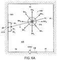
- FIG. 6Aillustrates one preferred embodiment of a navigational control system according to the present invention wherein the transmitting subsystem in integrated in combination with the robotic device and the receiving system functions as a base station mounted against one wall of a defined working area.
- FIG. 6Billustrates the set of transmitting units comprising the transmitting subsystem of the robotic device of FIG. 6A and representative directed beams having a predetermined emission patterns.
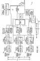
- FIG. 6Cis a schematic illustration of a preferred embodiment of the receiving subsystem of FIG. 6A .
- FIG. 7illustrates an exemplary embodiment of a navigational control system according to the present invention wherein the receiving subsystem is integrated in combination with the robotic device and the transmitting subsystem has a distributed configuration.
- FIG. 1is a top-view schematic of an exemplary preferred embodiment of a robotic device 100 having particular utility in combination with a navigational control system 10 according to the present invention.
- FIG. 2is a block diagram of the hardware of the robot device 100 of FIG. 1 .
- the hardware and behavioral modes (coverage behaviors for cleaning operations; escape behaviors for transitory movement patterns; and safety behaviors for emergency conditions) of the robotic device 100which is manufactured, distributed, and/or marketed by the iRobot Corporation of Burlington, Mass. under the ROOMBA trademark, are briefly described in the following paragraphs to facilitate a more complete understanding of the navigational control system 10 of the present invention. Further details regarding the hardware and behavioral modes of the robotic device 100 can be found in commonly-owned, co-pending U.S. nonprovisional patent application Ser. No. 10/167,851, filed 12 Jun. 2002, entitled M ETHOD AND S YSTEM FOR M ULTI -M ODE C OVERAGE FOR AN A UTONOMOUS R OBOT , and U.S. nonprovisional patent application Ser. No. 10/320,729, filed 16 Dec. 2002, entitled A UTONOMOUS F LOOR -C LEANING D EVICE.
- forwardrefers to the primary direction of motion (forward) of the robotic device (see arrow identified by reference character “FM” in FIG. 1 ).
- the fore/aft axis FA X of the robotic device 100coincides with the medial diameter of the robotic device 100 that divides the robotic device 100 into generally symmetrical right and left halves, which are defined as the dominant and non-dominant sides, respectively.
- the robotic device 100has a generally cylindrical housing infrastructure that includes a chassis 102 and an outer shell 104 secured to the chassis 102 that define a structural envelope of minimal height (to facilitate movement under furniture).
- the hardware comprising the robotic device 100can be generally categorized as the functional elements of a power system, a motive power system, a sensor system, a control module, a side brush assembly, or a self-adjusting cleaning head system, respectively, all of which are integrated in combination with the housing infrastructure.
- the robotic device 100further includes a forward bumper 106 having a generally arcuate configuration and a nose-wheel assembly 108 .
- the forward bumper 106(illustrated as a single component; alternatively, a two-segment component) is integrated in movable combination with the chassis 102 (by means of displaceable support members pairs) to extend outwardly therefrom. Whenever the robotic device 100 impacts an obstacle (e.g., wall, furniture) during movement thereof, the bumper 106 is displaced (compressed) towards the chassis 102 and returns to its extended (operating) position when contact with the obstacle is terminated.
- an obstaclee.g., wall, furniture
- the nose-wheel assembly 108is mounted in biased combination with the chassis 102 so that the nose-wheel subassembly 108 is in a retracted position (due to the weight of the robotic device 100 ) during cleaning operations wherein it rotates freely over the surface being cleaned.
- the nose-wheel subassembly 108encounters a drop-off during operation (e.g., descending stairs, split-level floors)
- the nose-wheel assembly 108is biased to an extended position.
- the hardware of the power systemwhich provides the energy to power the electrically-operated hardware of the robotic device 100 , comprises a rechargeable battery pack 110 (and associated conduction lines, not shown) that is integrated in combination with the chassis 102 .
- the motive power systemprovides the means that propels the robotic device 100 and operates the cleaning mechanisms, e.g., side brush assembly and the self-adjusting cleaning head system, during movement of the robotic device 100 .
- the motive power systemcomprises left and right main drive wheel assemblies 112 L, 112 R, their associated independent electric motors 114 L, 114 R, and electric motors 116 , 118 for operation of the side brush assembly and the self-adjusting cleaning head subsystem, respectively.
- the main drive wheel assemblies 112 L, 112 Rare independently mounted in biased combination with the chassis 102 (for pivotal motion with respect thereto) at opposed ends of the transverse diameter (with respect to the fore-aft axis FA X ) of the robotic device 100 and are in a retracted position (due to the weight of the robotic device 100 ) during operation thereof wherein the axes of rotation are approximately coplanar with the bottom of the chassis 102 .
- the main wheel assemblies 112 L, 112 Rare pivotally-biased to an extended position wherein their axes of rotation are below the bottom plane of the chassis 102 (in this extended position the rechargeable battery pack 110 is automatically turned off by the control module executing one of the safety behavioral modes).
- the electric motors 114 L, 114 Rare mechanically coupled to the main drive wheel assemblies 112 L, 112 R, respectively, and independently operated by control signals generated by the control module as a response to the implementation of a behavioral mode. Independent operation of the electric motors 114 L, 114 R allows the main wheel assemblies 112 L, 112 R to be: (1) rotated at the same speed in the same direction to propel the robotic device 100 in a straight line, forward or aft; (2) differentially rotated (including the condition wherein one wheel assembly is not rotated) to effect a variety of right and/or left turning patterns (over a spectrum of sharp to shallow turns) for the robotic device 100 ; and ( 3 ) rotated at the same speed in opposite directions to cause the robotic device 100 to turn in place, i.e., “spin on a dime”, to provide an extensive repertoire of movement capability for the robotic device 100 .
- the sensor systemcomprises a variety of different sensor units that are operative to generate signals that control the behavioral mode operations of the robotic device 100 .
- the described robotic device 100includes obstacle detection units 120 , cliff detection units 122 , wheel drop sensors 124 , an obstacle-following unit 126 , a virtual wall omnidirectional detector 128 , stall-sensor units 130 , and main wheel encoder units 132 .
- the obstacle (“bump”) detection units 120are IR break beam sensors mounted in combination with the displaceable support member pairs of the forward bumper 106 . These detection units 120 are operative to generate one or more signals indicating relative displacement between one or more support member pairs whenever the robotic device 100 impacts an obstacle such that the forward bumper 106 is compressed. These signals are processed by the control module to determine an approximate point of contact with the obstacle relative to the fore-aft axis FA X of the robotic device 100 (and the behavioral mode(s) to be implemented).
- the cliff detection units 122are mounted in combination with the forward bumper 106 .
- Each cliff detection unit 122comprises an IR emitter—detector pair configured and operative to establish a focal point such that radiation emitted downwardly by the emitter is reflected from the surface being traversed and detected by the detector. If reflected radiation is not detected by the detector, i.e., a drop-off is encountered, the cliff detection unit 122 transmits a signal to the control module (which causes one or more behavioral modes to be implemented).
- a wheel drop sensor 124such as a contact switch is integrated in combination with each of the main drive wheel assemblies 112 L, 112 R and the nose wheel assembly 108 and is operative to generate a signal whenever any of the wheel assemblies is in an extended position, i.e., not in contact with the surface being traversed, (which causes the control module to implement one ore more behavioral modes).
- the obstacle-following unit 126 for the described embodimentis an IR emitter—detector pair mounted on the ‘dominant’ side (right hand side of FIG. 1 ) of the robotic device 100 .
- the emitter—detector pairis similar in configuration to the cliff detection units 112 , but is positioned so that the emitter emits radiation laterally from the dominant side of the robotic device 100 .
- the unit 126is operative to transmit a signal to the control module whenever an obstacle is detected as a result of radiation reflected from the obstacle and detected by the detector.
- the control modulein response to this signal, causes one or more behavioral modes to be implemented.
- a virtual wall detection system for use in conjunction with the described embodiment of the robotic device 100comprises an omnidirectional detector 128 mounted atop the outer shell 104 and a stand-alone transmitting unit (not shown) that transmits an axially-directed confinement beam.
- the stand-alone transmitting unitis positioned so that the emitted confinement beam blocks an accessway to a defined working area, thereby restricting the robotic device 100 to operations within the defined working area (e.g., in a doorway to confine the robotic device 100 within a specific room to be cleaned).
- the omnidirectional detector 128Upon detection of the confinement beam, transmits a signal to the control module (which causes one or more behavioral modes to be implemented to move the robotic device 100 away from the confinement beam generated by the stand-alone transmitting unit).
- a stall sensor unit 130is integrated in combination with each electric motor 114 L, 114 R, 116 , 118 and operative to transmit a signal to the control module when a change in current is detected in the associated electric motor (which is indicative of a dysfunctional condition in the corresponding driven hardware).
- the control moduleis operative in response to such a signal to implement one or more behavioral modes.
- An IR encoder unit 132(see FIG. 2 ) is integrated in combination with each main wheel assembly 112 L, 112 R and operative to detect the rotation of the corresponding wheel and transmit signals corresponding thereto the control module (wheel rotation can be used to provide an estimate of distance traveled for the robotic device 100 ).
- the control modulecomprises the microprocessing unit 135 illustrated in FIG. 2 that includes I/O ports connected to the sensors and controllable hardware of the robotic device 100 , a microcontroller, and ROM and RAM memory.
- the I/O portsfunction as the interface between the microcontroller and the sensor units and controllable hardware, transferring signals generated by the sensor units to the microcontroller and transferring control (instruction) signals generated by the microcontroller to the controllable hardware to implement a specific behavioral mode.
- the microcontrolleris operative to execute instruction sets for processing sensor signals, implementing specific behavioral modes based upon such processed signals, and generating control (instruction) signals for the controllable hardware based upon implemented behavioral modes for the robotic device 100 .
- the cleaning coverage and control programs for the robotic device 100are stored in the ROM of the microprocessing unit 135 , which includes the behavioral modes, sensor processing algorithms, control signal generation algorithms and a prioritization algorithm for determining which behavioral mode or modes are to be given control of the robotic device 100 .
- the RAM of the microprocessing unit 135is used to store the active state of the robotic device 100 , including the ID of the behavioral mode(s) under which the robotic device 100 is currently being operated and the hardware commands associated therewith.
- the side brush assembly 140is configured and operative to entrain particulates outside the periphery of the housing infrastructure and to direct such particulates towards the self-adjusting cleaning head system.
- the side brush assembly 140provides the robotic device 100 with the capability of cleaning surfaces adjacent to base-boards when the robotic device is operated in an Obstacle-Following behavioral mode.
- the side brush assembly 140is preferably mounted in combination with the chassis 102 in the forward quadrant on the dominant side of the robotic device 100 .
- the self-adjusting cleaning head system 145 for the described robotic device 100comprises a dual-stage brush assembly and a vacuum assembly, each of which is independently powered by an electric motor (reference numeral 118 in FIG. 1 actually identifies two independent electric motors—one for the brush assembly and one for the vacuum assembly).
- the cleaning capability of the robotic device 100is commonly characterized in terms of the width of the cleaning head system 145 (see reference character W in FIG. 1 ).
- the dual-stage brush assembly and the inlet of the vacuum assemblyare integrated in combination with a deck structure, which is pivotally mounted in combination with the chassis 102 and operatively integrated with the motor of the dual-stage brush assembly.
- the brush assembly motorprovides the motive force to pivot the deck structure with respect to the chassis 102 .
- the pivoting deck structureprovides the self adjusting capability for the cleaning head assembly 145 , which allows the robotic device 100 to readily transition between disparate surfaces during cleaning operations, e.g., carpeted surface to bare surface or vice versa, without hanging up.
- the dual-stage brush assemblycomprises asymmetric, counter-rotating brushes that are positioned (forward of the inlet of the vacuum assembly), configured and operative to direct particulate debris into a removable dust cartridge (not shown).
- the positioning, configuration, and operation of the brush assemblyconcomitantly directs particulate debris towards the inlet of the vacuum assembly such that particulates that are not swept up by the dual-stage brush assembly can be subsequently ingested by the vacuum assembly as a result of movement of the robotic device 100 .
- Operation of the vacuum assembly independently of the self-adjustable brush assemblyallows the vacuum assembly to generate and maintain a higher vacuum force using a battery-power source than would be possible if the vacuum assembly were operated in dependence with the brush assembly.
- the robotic device 100uses a variety of behavioral modes to effectively clean a defined working area where behavioral modes are layers of control systems that can be operated in parallel.
- the microprocessor unit 135is operative to execute a prioritized arbitration scheme to identify and implement one or more dominant behavioral modes for any given scenario based upon inputs from the sensor system.
- the behavioral modes for the described robotic device 100can be characterized as: (1) coverage behavioral modes; (2) escape behavioral modes; and (3) safety behavioral modes.
- Coverage behavioral modesare primarily designed to allow the robotic device 100 to perform its cleaning operations in an efficient and effective manner and the escape and safety behavioral modes are priority behavioral modes implemented when a signal from the sensor system indicates that normal operation of the robotic device 100 is impaired, e.g., obstacle encountered, or is likely to be impaired, e.g., drop-off detected.
- Representative and illustrative coverage behavioral (cleaning) modes for the robotic device 100include: (1) a Spot Coverage pattern; (2) an Obstacle-Following (or Edge-Cleaning) Coverage pattern, and ( 3 ) a Room Coverage pattern.
- the Spot Coverage patterncauses the robotic device 100 to clean a limited area within the defined working area, e.g., a high-traffic area.
- the Spot Coverage patternis implemented by means of a spiral algorithm (but other types of self-bounded area algorithms, e.g., polygonal, can be used).
- the spiral algorithmwhich causes outward spiraling (preferred) or inward spiraling movement of the robotic device 100 , is implemented by control signals from the microprocessing unit 135 to the main wheel assemblies 112 L, 112 R to change the turn radius/radii thereof as a function of time (thereby increasing/decreasing the spiral movement pattern of the robotic device 100 ).
- the robotic device 100is operated in the Spot Coverage pattern for a predetermined or random period of time, for a predetermined or random distance (e.g., a maximum spiral distance) and/or until the occurrence of a specified event, e.g., activation of one or more of the obstacle detection units 120 (collectively a transition condition).
- a transition conditionoccurs, the robotic device 100 can implement or transition to a different behavioral mode, e.g., a Straight Line behavioral mode (in a preferred embodiment of the robotic device 100 , the Straight Line behavioral mode is a low priority, default behavior that propels the robot in an approximately straight line at a preset velocity of approximately 0.306 m/s) or a Bounce behavioral mode in combination with a Straight Line behavioral mode.
- a Straight Line behavioral modein a preferred embodiment of the robotic device 100 , the Straight Line behavioral mode is a low priority, default behavior that propels the robot in an approximately straight line at a preset velocity of approximately 0.306 m/s
- Bounce behavioral modein combination with
- the robotic device 100can take other actions in lieu of transitioning to a different behavioral mode.
- the robotic device 100can momentarily implement a behavioral mode to avoid or escape the obstacle and resume operation under control of the spiral algorithm (i.e., continue spiraling in the same direction).
- the robotic device 100can momentarily implement a behavioral mode to avoid or escape the obstacle and resume operation under control of the spiral algorithm (but in the opposite direction—reflective spiraling).
- the Obstacle-Following Coverage patterncauses the robotic device 100 to clean the perimeter of the defined working area, e.g., a room bounded by walls, and/or the perimeter of an obstacle (e.g., furniture) within the defined working area.
- the robotic device 100utilizes obstacle-following unit 126 to continuously maintain its position with respect to an obstacle, e.g., wall, furniture, so that the motion of the robotic device 100 causes it to travel adjacent to and concomitantly clean along the perimeter of the obstacle.
- Different embodiments of the obstacle-following unit 126can be used to implement the Obstacle-Following behavioral pattern.
- the obstacle-following unit 126is operated to detect the presence or absence of the obstacle. In an alternative embodiment, the obstacle-following unit 126 is operated to detect an obstacle and then maintain a predetermined distance between the obstacle and the robotic device 100 .
- the microprocessing unit 135is operative, in response to signals from the obstacle-following unit, to implement small CW or CCW turns to maintain its position with respect to the obstacle.
- the robotic device 100implements a small CW when the robotic device 100 transitions from obstacle detection to non-detection (reflection to non-reflection) or to implement a small CCW turn when the robotic device 100 transitions from non-detection to detection (non-reflection to reflection). Similar turning behaviors are implemented by the robotic device 100 to maintain the predetermined distance from the obstacle.
- the robotic device 100is operated in the Obstacle-Following behavioral mode for a predetermined or random period of time, for a predetermined or random distance (e.g., a maximum or minimum distance) and/or until the occurrence of a specified event, e.g., activation of one or more of the obstacle detection units 120 a predetermined number of times (collectively a transition condition).
- the microprocessor 135will cause the robotic device to implement an Align behavioral mode upon activation of the obstacle-detection units 120 in the Obstacle-Following behavioral mode wherein the implements a minimum angle CCW turn to align the robotic device 100 with the obstacle.
- the Room Coverage patterncan be used by the robotic device 100 to clean any defined working area that is bounded by walls, stairs, obstacles or other barriers (e.g., a virtual wall unit).
- a preferred embodiment for the Room Coverage patterncomprises the Random-Bounce behavioral mode in combination with the Straight Line behavioral mode. Initially, the robotic device 100 travels under control of the Straight-Line behavioral mode, i.e., straight-line algorithm (main drive wheel assemblies 112 L, 112 R operating at the same rotational speed in the same direction) until an obstacle is encountered.
- the microprocessing unit 135operative to compute an acceptable range of new directions based upon the obstacle detection unit(s) 126 activated.
- the microprocessing unit 135selects a new heading from within the acceptable range and implements a CW or CCW turn to achieve the new heading with minimal movement.
- the new turn headingmay be followed by forward movement to increase the cleaning efficiency of the robotic device 100 .
- the new headingmay be randomly selected across the acceptable range of headings, or based upon some statistical selection scheme, e.g., Gaussian distribution.
- the microprocessing unit 135can be programmed to change headings randomly or at predetermined times, without input from the sensor system.
- the robotic device 100is operated in the Room Coverage behavioral mode for a predetermined or random period of time, for a predetermined or random distance (e.g., a maximum or minimum distance) and/or until the occurrence of a specified event, e.g., activation of the obstacle-detection units 120 a predetermined number of times (collectively a transition condition).
- a predetermined or random distancee.g., a maximum or minimum distance
- a specified evente.g., activation of the obstacle-detection units 120 a predetermined number of times (collectively a transition condition).
- a preferred embodiment of the robotic device 100includes four escape behavioral modes: a Turn behavioral mode, an Edge behavioral mode, a Wheel Drop behavioral mode, and a Slow behavioral mode.
- a Turn behavioral modea Turn behavioral mode
- an Edge behavioral modea Wheel Drop behavioral mode
- a Slow behavioral modea behavioral mode that can be utilized by the robotic device 100 .
- One or more of these behavioral modesmay be implemented, for example, in response to a current rise in one of the electric motors 116 , 118 of the side brush assembly 140 or dual-stage brush assembly above a low or high stall threshold, forward bumper 106 in compressed position for determined time period, detection of a wheel-drop event.
- the robotic device 100turns in place in a random direction, starting at higher velocity (e.g., twice normal turning velocity) and decreasing to a lower velocity (one-half normal turning velocity), i.e., small panic turns and large panic turns, respectively.
- Low panic turnsare preferably in the range of 45° to 90°
- large panic turnsare preferably in the range of 90° to 270°.
- the Turn behavioral modeprevents the robotic device 100 from becoming stuck on room impediments, e.g., high spot in carpet, ramped lamp base, from becoming stuck under room impediments, e.g., under a sofa, or from becoming trapped in a confined area.
- the Edge behavioral modefollows the edge of an obstacle unit it has turned through a predetermined number of degrees, e.g., 60°, without activation of any of the obstacle detection units 120 , or until the robotic device has turned through a predetermined number of degrees, e.g., 170°, since initiation of the Edge behavioral mode.
- the Edge behavioral modeallows the robotic device 100 to move through the smallest possible openings to escape from confined areas.
- the microprocessor 135In the Wheel Drop behavioral mode, the microprocessor 135 reverses the direction of the main wheel drive assemblies 112 L, 112 R momentarily, then stops them. If the activated wheel drop sensor 124 deactivates within a predetermined time, the microprocessor 135 then reimplements the behavioral mode that was being executed prior to the activation of the wheel drop sensor 124 .
- the Slow behavioral modeis implemented to slowed down the robotic device 100 for a predetermined distance and then ramped back up to its normal operating speed.
- a safety conditione.g., a series of brush or wheel stalls that cause the corresponding electric motors to be temporarily cycled off, wheel drop sensor 124 or a cliff detection sensor 122 activated for greater that a predetermined period of time, the robotic device 100 is generally cycled to an off state.
- an audible alarmmay be generated.
- FIG. 3is a schematic representation of a navigational control system 10 according to the present invention for use in combination with a robotic device 100 to enhance the cleaning efficiency thereof by adding a deterministic component (in the form of a control signal that remotely controls the movement of the robotic device 100 ) to the motion algorithms, including random motion, autonomously implemented by the robotic device 100 .
- the navigational control system 10comprises a transmitting subsystem 12 and a receiving subsystem 20 operating under the direction of a navigation control algorithm.
- the navigation control algorithmincludes a definition of a predetermined triggering event.
- the specific features and characteristics of the transmitting subsystem 12 and the receiving subsystem 20depend upon whether the particular subsystem is integrated in combination with the robotic device 100 or functions as a “base station” for the navigational control system 10 .
- the navigational control system 10is operative, under the direction of the navigation control algorithm, to monitor the movement activity of the robotic device 100 within the defined working area.
- the monitored movement activityis defined in terms of the “position history” of the robotic device 100 as described in further detail below.
- the monitored movement activityis defined in terms of the “instantaneous position” of the robotic device 100 as defined in further detail below.
- the predetermined triggering eventis a specific occurrence or condition in the movement activity of the robotic device 100 .
- the navigational control system 10is operative to generate and communicate a control signal to the robotic device 100 .
- the robotic device 100is operative to implement or execute a conduct prescribed by the control signal, i.e., the prescribed conduct. This prescribed conduct represents a deterministic component of the movement activity of the robotic device 100 .
- the system 10is configured and operative to create a “tessellation” of any defined working area where the robotic device 100 is to be operated, e.g., a room to be cleaned.
- Tessellateis used herein in the sense that the defined working area is segmented into a set of individual cells, which may or may not be of equal size.
- FIG. 4exemplarily illustrates the polar tessellation of a defined working area into a set of individual cells C (reference characters BS T identify the “base station”) of unequal size.
- each cell C(in terms of its center) is identified in terms of polar coordinates (r, ⁇ ) referenced to the base station BS T as the origin (0, 0).
- a grid map of the cells C comprising the defined working areais stored in memory of the navigation control system 10 .
- coordinate systemse.g., a planar Cartesian coordinate system, can be used by the navigational control system 10 to define the position of individual cells C within the predetermined working area.
- the navigational control system 10is operative to define the size the individual cells C so that the length and width dimensions of an individual cell C are no larger than one-half the width (W) of the cleaning head system 145 of the robotic device 100 (see FIG. 1 and corresponding discussion above).
- the navigational control system 10is operative to generate a position history of the robotic device 100 within the defined working area in terms of such individual cells C (to minimize the memory requirements for storage of position history).
- the position historycomprises a set of discrete, instantaneous positions (in terms of individual cells C) of the robotic device 100 over a time interval where the time interval is a variable that depends upon the “triggering condition” of the navigation control algorithm implemented by the navigational control system 10 .
- Each discrete instantaneous position of the robotic device 100is determined by operating the transmitting subsystem 12 to emit a set of directional beams and operating the receiving subsystem 20 to detect one or more of such directional beams and process a signal parameter of the detected beam(s) to determine an absolute bearing parameter and a distance parameter between the transmitting subsystem 12 and the receiving subsystem 20 at a point in time.
- Each pair of bearing, distance parametersestablishes a discrete instantaneous position for the robotic device 100 .
- the navigational control system 10is operative to correlate each discrete instantaneous position to one individual cell C of the grid map.
- a set of bearing and position pairs, i.e., a set of instantaneous positions, over a time intervaldefines a set of cells C, which are identified in the receiving subsystem 20 as the position history of the robotic device 100 for the time interval.
- the system 10processes each discrete instantaneous position as it is established, under the control of the navigation control algorithm, to determine whether such discrete instantaneous position is the predetermined triggering event defined by the navigation control algorithm.
- the system 10is additionally configured and operative to determine a travel vector (indicating the direction of motion of the robotic device 100 within an individual cell C or at the discrete instantaneous position) at each point in time. These travel vectors may be stored in memory in conjunction with the corresponding cells C as a component of the position history of the robotic device 100 .
- the navigational control system 10is further operative, under direction of the navigational control algorithm, to generate and communicate a control signal to the robotic device 100 whenever the navigational control system 100 realizes the predetermined triggering event.
- the robotic device 100is configured and operative to initiate a prescribed conduct.
- the prescribed conductcomprises the deterministic component added to the random motion movement activity of the robotic device 100 by means of the navigational control system 10 according to the present invention.
- the prescribed conduct of the robotic device 100comprises one or more basic maneuvers such as CW and CCW turns, forward or aft (straight line) movement, slow down, speed up, and stop.
- the CW and/or CCW turnscan be implemented using the turning techniques of the robotic device 100 described above, and the turn angles can be, for example, over a 360° spectrum at predetermined intervals, e.g., 5° or 10°.
- the CW and/or CCW turnscan be to a specified azimuthal heading (referenced to the base station as the origin) where the navigational control system 10 is configured and operative so that the travel vector is a determinable variable.
- forward (straight line) movementis typically the default maneuver that the robotic device 100 automatically reverts to (implements) once one or more of the other basic maneuvers has been completed.
- the prescribed conduct of the robotic device 100comprises one or more of the behavioral modes described herein. In yet a further preferred embodiment of the invention, the prescribed conduct of the robotic device 100 comprises a combination of the basic maneuvers and the behavioral modes described herein.
- the transmitting subsystem 12is operative to transmit a number of directed beams having a predetermined emission pattern along a specific propagation axis.
- the directed beamsare planar, i.e., substantially parallel to the surface of the defined working area.
- the transmitting subsystem 12is integrated in combination with the robotic device 100 .
- the transmitting subsystem 12is configured and operative to functionally emulate an omnidirectional transmission source with respect to the defined working area, i.e., by emitting a plurality of directed beams that cover the defined working area.
- the robotic device 100further includes a receiver unit 16 (see FIG. 3 ) configured and operative to receive control signals from the receiving subsystem 20 (see discussion below regarding the transmitting unit 32 of the receiving subsystem 20 ). While the receiver unit 16 is depicted as a dedicated receiving unit for the control signals, it is preferable that the omnidirectional detector 128 (of the virtual wall detection system) described above be adapted to detect and process such control signals.
- the transmitting subsystem 12comprises a conventional mechanical sweeping transmitter, e.g., a laser, that is integrated in combination with a high point of the housing infrastructure of the robotic device 100 so that none of the structural features of the robotic device 100 interfere with the operation thereof.
- the mechanical sweeping transmitteris configured and operative to emit the plurality of directed beams while concomitantly redirecting (mechanically sweeping) the transmitting element so that each directed beam has a different propagation axis.
- Other features and characteristics of the mechanical sweeping transmitterare described below in terms of individual transmitting units 14 N for ease of description.
- the transmitting subsystem 12comprises a set of transmitting units 14 N , where N is an integer defining the number of individual transmitting units comprising the set for the navigational control system 10 , that are integrated in combination with the robotic device 100 about the periphery of its housing infrastructure.
- Each transmitting unit 14 Nis configured and operative to emit a directed beam having a predetermined emission pattern along a specific propagation axis.
- the transmitting subsystem 12is configured and operative so that the emitted directed beams are planar.
- the transmitting units 14 Nare fungible/interchangeable, each operating to emit a directed beam at a common operating frequency.
- the common operating frequency for the transmitting units 14 Nlies in the infrared range, i.e., about 750 nm to about 1.4 ⁇ 10 4 nm, preferably about 880 nm to about 980 nm, although one skilled in the art will appreciate that other wavelengths, e.g., in the radio frequency range, microwave frequency range, can be used in the practice of the navigational control system 10 of the present invention.
- the common operating frequency directed beams emitted by the transmitting units 14 Nare periodically modulated, e.g., at 10 KHz for 50 msec, off for 300 msec. Modulation of the directed beams facilitates detection thereof by the receiving subsystem 20 , i.e., the receiving subsystem 20 is able to readily discriminate between modulated directed beams emitted by the transmitting subsystem 12 and any other electromagnetic radiation sources that may be active in the defined working area, e.g., television remote control units, wireless computer keyboards, microwaves, ambient radiation such as sunlight.
- any other electromagnetic radiation sourcesthat may be active in the defined working area, e.g., television remote control units, wireless computer keyboards, microwaves, ambient radiation such as sunlight.
- the transmitting units 14 Nbe sequentially operated so that any transmitting unit 14 N is cycled on for a predetermined period of time and then cycled off, the next (adjacent) transmitting unit 14 N is then cycled on for the predetermined period of time and cycled off, and so forth.
- a navigational control system 10 employing the basic embodiment of the transmitting subsystem 12i.e., all transmitting units 14 N are interchangeable—emitting directed beams at a common operating frequency, cannot be used to determine travel vectors for the robotic device 100 because the receiving subsystem 20 cannot differentiate between directed beams emitted by the transmitting units 14 N and therefore cannot identify any particular transmitting unit 14 N .
- the inventorshave developed two innovative ways of transmitting and processing directed beams emitted by a transmitting subsystem 12 comprised of interchangeable transmitting units 14 N so that the receiving subsystem 20 can individually identify a specific interchangeable transmitting unit 14 N, and, based upon such identification, establish a travel vector for the robotic device 100 .
- interchangeable transmitting units 14 Nare operated in a predetermined manner that allows the receiving subsystem 20 to process detected directed beams to identify the directed beam having the highest signal strength, which, in turn, allows the receiving subsystem 20 to identify the interchangeable transmitting unit 14 N that emitted such directed beam. This, in turn, allows the receiving subsystem 20 to determine the orientation and, hence the travel vector, of the robotic device 100 .
- the transmitting subsystem 12is first cycled on so that all transmitting units 14 N emit directed beams for a predetermined synchronization period, as identified by reference character t SY , and then cycled off.
- the receiver subsystem 20is operative to detect and process one or more of the directed beams emitted by the transmitting units 14 N and identify the predetermined synchronization period t SY of the transmitting subsystem 12 . This identification allows the receiving subsystem 20 to synchronize operations between the transmitting subsystem 12 and the receiving subsystem 20 by initializing a timing sequence at the end of the predetermined synchronization period t SY (reference character t 0 identifies the initialization of the timing sequence in FIG. 5A ).
- the transmitting subsystem 12is further operative so that individual transmitting unit 14 N are sequentially cycled on and off at predetermined times with respect to the timing sequence initialization t 0 established by the receiving subsystem 20 .
- FIG. 5Awhich illustrates a transmitting subsystem 12 comprising four transmitting units 14 N (arbitrarily identified as the first transmitting unit 14 1 , the second transmitting unit 14 2 , the third transmitting unit 14 3 , and the fourth transmitting unit 14 4 )
- the transmitting subsystem 12is configured and operative so that each of the transmitting units 14 1 , 14 2 , 14 3 , 14 4 is sequentially cycled on to emit a directed beam that transitions from a zero (0) signal strength to a peak signal strength to a zero (0) signal strength and then cycled off (a saw-tooth transition pattern is exemplarily illustrated in FIG. 5 A—one skilled in the art will appreciate that other types of signal strength transition patterns can be used in the practice of the invention described herein, e.g.,
- the first transmitting unit 14 1is cycled on and transitions to a peak signal strength at time t 1 .
- the second transmitting unit 14 2is cycled on as the directed beam from the first transmitting unit 14 1 achieves its peak signal strength at time t 1 .
- the second transmitting unit 14 2transitions to a peak signal strength at time t 2 , at which point the first transmitting unit 14 1 has transitioned to a zero (0) signal strength and is cycled off.
- the third transmitting unit 14 3is cycled on as the directed beam from the second transmitting unit 14 2 achieves its peak signal strength at time t 2 .
- the foregoing operating patternis repeated for the second, third, and fourth transmitting units 14 2 , 14 3 , 14 4 , as applicable, so that at time t 3 the second transmitting unit 14 2 is cycled off, the directed beam emitted by the third transmitting unit 14 3 has achieved its peak signal strength, and the fourth transmitting unit 14 4 is cycled on; and at time t 4 the third transmitting unit 14 3 is cycled off and the directed beam emitted by the fourth transmitting unit 14 4 has achieved its peak strength.
- the transmitting subsystem 12is operative to repeat the above-described synchronization—sequential transmission procedure during operation of the navigational control system 12 according to the present invention.
- interchangeable transmitting units 14 Nare operated in a different predetermined manner that allows the receiving subsystem 20 to process detected directed beams to identify the directed beam having the highest signal strength, which, in turn, allows the receiving subsystem 20 to identify the interchangeable transmitting unit 14 N that emitted such directed beam. This, in turn, allows the receiving subsystem 20 to determine the orientation and, hence the travel vector, of the robotic device 100 .
- the transmitting subsystem 12is first cycled on so that all transmitting units 14 N emit directed beams for a predetermined synchronization period, as identified by reference character t 12 , and then cycled off.
- the receiver subsystem 20is operative to detect and process one or more of the directed beams emitted by the transmitting units 14 N and identify the predetermined synchronization period t 12 of the transmitting subsystem 12 . This identification allows the receiving subsystem 20 to synchronize operations between the transmitting subsystem 12 and the receiving subsystem 20 by initializing a timing sequence at the end of the predetermined synchronization period t SY (reference character t 0 identifies the initialization of the timing sequence in FIG. 5A ).
- the transmitting subsystem 12is further operative so that individual transmitting unit 14 N are sequentially cycled on and off at predetermined times with respect to the timing sequence initialization t 0 established by the receiving subsystem 20 .
- FIG. 5Cwhich illustrates a transmitting subsystem 12 comprising four transmitting units 14 N (arbitrarily identified as the first transmitting unit 14 1 , the second transmitting unit 14 2 , the third transmitting unit 14 3 , and the fourth transmitting unit 14 4 )
- the transmitting subsystem 12is configured and operative so that each of the transmitting units 14 1 , 14 2 , 14 3 , 14 4 is sequentially cycled on to emit a pulsed directed beam have a predetermined pulse width P 1 , P 2 , P 3 , P 4 , respectively, at a predetermined signal strength, and then cycled off.
- the first transmitting unit 14 1is cycled on at t 11 (where the first “1” identifies the transmitting unit number and the second “1” indicates that the transmitting unit is cycled on) and cycled off at t 12 (where the “2” indicates that the transmitting unit is cycled off).
- the second transmitting unit 14 2is cycled on at t 21 and cycled off at t 22
- the third transmitting unit 14 3is cycled on at t 31 and cycled off at t 32
- fourth transmitting units 14 4is cycled on at t 41 and cycled off at t 42 .
- the transmitting subsystem 12is operative to repeat the above-described synchronization—sequential transmission procedure during operation of the navigational control system 12 according to the present invention.
- the transmitting units 14 Nare discrete and identifiable, each transmitting unit 14 N operating at a unique operating frequency to emit a directed beam (which is preferably planar with respect to the surface of the defined working area) having a predetermined emission pattern along a specific propagation axis. These operating frequencies are also preferably modulated to facilitate detection thereof by the receiving subsystem 20 in an environment where other electromagnetic radiation sources are operating. Since each directed beam is readily and uniquely identifiable, the receiving subsystem 20 can process detected directed beams in a conventional manner to derive not only the absolute bearing and to the robotic device 100 , but also the travel vector for the robotic device 10 at any particular time.
- the receiving subsystem 20 of the navigational control system 10comprises a processing unit 22 that includes a microprocessor 24 , a signal processing unit 26 , a memory module 28 , and a set of detection units 30 M . Additionally, the receiving subsystem 20 can also include a transmitting unit 32 for those preferred embodiments of the navigational control system 10 wherein the receiving subsystem 20 is operated or functions as the base station for the navigational control system 10 .
- the memory module 28comprises RAM 28 A and ROM 28 B.
- Data relating to the current operation of the robotic device 100 within the defined working areais stored in the RAM 28 A.
- Such current operational datacan include the grid map of cells C defining the defined working area and the position history of the robotic device 100 within the defined working area for the ‘position history’ embodiment of the navigational control system 10 .
- Stored in the ROM 28 Bare one or more navigation control algorithms for the navigational control system 10 , a set of one or more control signals associated with each navigation control algorithm, and a signal processing algorithm for converting signals generated by the signal processing unit 26 to one or more sets of instantaneous position parameters, i.e., a bearing, distance pair (and travel vector, if applicable).
- a set of instantaneous position parametersthat define the position history of the robotic device 100 , which are correlated with the grid map to identify the cells C comprising the position history.
- vigation control algorithmencompasses a set of instructions that: (a) define how the position history or instantaneous position is used by the navigational control system 10 (e.g., counting and comparing cells visited, a true-false determination for cells visited, true-false determination whether the predetermined triggering event has occurred); (b) defines the triggering event or events associated with the use of the position history or the instantaneous position; and (c) identifies the control signal(s) to be implemented when the triggering event is realized.
- the microprocessor 24is operative to count and store the number of visits to each cell and to compute the total number of visits to cells contiguous to (neighboring) each such visited cell (cell counting). The microprocessor 24 is further operative to compare the total number of neighboring-cell visits as each cell is visited to a threshold value (see, e.g., FIG. 4 wherein “C V ” identifies a visited cell and “C C ” identifies the eight (8) cells contiguous to the visited cell C V ). If the total number of neighboring-visits (e.g., fifteen (15) in the example of FIG.
- the microprocessor 24is operative to cause a control signal to be communicated to the robotic device 100 .
- the control signalcauses the robotic device 100 to implement one or more behavioral modes specified by the control signal, e.g., a Spot Coverage pattern as described above.
- one or more cells in the stored grid mapare pre-identified (i.e., prior to operating the robotic device 100 ) as “hot spots” in the defined working area.
- the microprocessor 24is operative to determine whether the visited cell has been identified as a “hot spot” (true-false determination). If the microprocessor 24 determines that the visited cell C is a “hot spot” (triggering event), the microprocessor 24 is operative to cause a control signal to be communicated to the robotic device 100 via the control signal transmitting unit 32 . Reception of the control signal causes the robotic device 100 to implement the prescribed conduct specified by the control signal, e.g., one or more of the basic maneuvers described above and/or a Spot Coverage pattern or Obstacle-Following behavioral mode as described above.
- navigation control algorithms for the ‘position history’ embodiment of the navigational control system 10are implemented without knowledge of the travel vector of the robotic device 100 , i.e., based solely upon the identification of visited cells by means of the bearing, distance parameters derived by the receiving subsystem 20 .
- Another representative example of a navigation control algorithm for the ‘position history’ embodiment of the navigation control system 10 of the present inventionutilizes the travel vector as an element of the position history in issuing a control signal.
- the microprocessor 24is operative to count and store the number of times a cell has been visited (cell counting) and further operative to compare this number to the number of times each contiguous (or neighboring) cell has been visited.
- the triggering eventis a numerical differential between the number of visits to the currently-visited cell number and the number of visits to each of the neighboring-cells that identifies the neighboring cell or cells that have been least-visited as compared to the currently-visited cell.
- the triggering eventwould cause the receiving system 20 to issue a control signal to the robotic device 100 that causes the robotic device 100 to move from the currently-visited cell to the neighboring cell that has been visited least, e.g., by implementing one or more basic maneuvers as described herein. If two or more neighboring cells have been visited least, the control signal would cause the robotic device to move from the currently-visited cell to the least visited neighboring cell that is most compatible with the current travel vector of the robotic device 100 , e.g., minimum travel distance.
- the neighboring cells C C that have been visited a single timeare the least-visited neighboring cells C C . If the current travel vector for the robotic device 100 is indicated by the reference characters TV, the control signal would cause the robotic device 100 to continue moving in a straight line, i.e., the move forward basic maneuver (or the Straight-Line behavioral mode) would be executed by the robotic device 100 (if the robotic device 100 was currently operating in some other behavioral mode).
- One representative navigation control algorithm for the ‘instantaneous position’ of the navigational control system 10uses elapsed time (either random or predetermined) as the predetermined triggering event to cause the robotic device 10 to move to a predetermined position B in the defined working environment.
- the microprocessor 24is operative, upon expiration of the elapsed time (the predetermined triggering event), to determine the instantaneous position (hereinafter identified as “position A”) of the robotic device 100 as described herein. Since position A is an unknown variable until the predetermined triggering event is realized, the prescribed conduct, i.e., the basic maneuvers, necessary to move the robotic device 100 from position A to position B are also unknown.
- the basic maneuvers necessary to move the robotic device 100 from position A to position Bare determinable since both position A and position B are known variables (in terms of their known bearing, distance parameter pairs with respect to the receiving subsystem 20 ).
- a determination of the basic maneuvers that will be implemented by the robotic device 100can be accomplished by any conventional computational technique.
- Another exemplary navigation control algorithm for the ‘instantaneous position’ embodiment of the navigational control system 10is a variation of the “hot spot” navigation control algorithm for the ‘position history’ embodiment of the navigational control system 10 .
- both position A and position Bare known variables and accordingly, the basic maneuver(s) to move the robotic device 100 from position A to position B are known.
- the predetermined triggering eventis a TRUE determination that the instantaneous position of the robotic device 100 is equal to position A (position A may be stored in memory 28 as a “zone”—defining some arbitrary area centered about position A—rather than a single point position to increase the probability that the instantaneous position of the robotic device 100 at some time will equal position A).
- the receiving subsystem 20comprises a set of detection units 30 M where M is an integer defining the number of individual detection units comprising the set for the navigational control system 10 .
- Mis an integer defining the number of individual detection units comprising the set for the navigational control system 10 .
- the number and positioning of the set of detection units 30 Mshould be such that as much of the defined working area as possible is within the field-of-view of the receiving subsystem 20 and that the fields-of-view of at least two (but preferably more) detection units 30 M cover the same area within the defined working area.
- the receiving subsystem 20functions as a “base station” for the system 10 .
- the receiving subsystem 20is a portable, standalone unit that is stationarily positioned within the defined working area, preferably abutting a wall bounding the defined working area (the ‘wall unit’ configuration).
- the receiving subsystem 20can be positioned within the defined working area distally of the walls bounding the defined working area (the ‘free-standing’ configuration).
- the receiving subsystem 20 as the base stationestablishes and, for the ‘position history’ embodiment of the navigational control system 10 , stores the grid map of cells representing the defined working area and represents the origin (0, 0) of the grid map of cells described above.
- the individual detection units 30 Mhave a known spaced-apart relationship and configured and operative to have a 180° field-of-view.
- Preferred embodiments of the wall unit configuration for the navigational control system 10include three detection units 30 M to provide absolute bearing data to the robotic device 100 .
- a minimum of two detection units 30 Mare required to provide the necessary signal information for the receiving subsystem 20 .
- More than three detection units 30 Mcan be employed to increase the resolution of the receiving subsystem 20 , but at an added cost for each additional detection unit 30 M and associated signal processing circuitry (see FIG. 6C which illustrates the representative signal processing circuitry associated with a detection unit 30 M ).
- the individual detection units 30 Mlikewise spaced apart by known angular distances and configured and operative have a field-of-view greater than 180°.
- a representative embodiment of the receiving subsystem 20 operated as a free-standing base stationwould comprise four detection units 30 M .
- the detection units 30 Mare configured and operative to detect a parameter of one or more of the directed beams emitted by the transmitting units 14 N , e.g., voltages V representing the relative signal strengths of the detected directed beam(s).
- each detection unit 30 Mis configured and operative to average the detected signal strength parameter (e.g., voltage) when the detection unit 30 M detects two directed beams simultaneously.
- the receiving subsystem 20executes a signal processing algorithm that processes the detected parameters provided by the detection units 30 M, i.e., relative signal strengths of the detected beams, utilizing a conventional technique to determine the absolute bearing between the robotic device 100 and the receiving subsystem 20 .
- the receiving subsystem 20is preferably calibrated prior to use. This involves positioning the robotic device 100 at a predetermined distance from the receiving subsystem 20 and operating one (or more) of the transmitting units 14 N to emit a directed beam at the receiving subsystem 20 .
- the parameter of the directed beam detected by the detection units 30 Me.g., a voltage representing the signal strength of the directed beam as detected, is correlated to the predetermined distance and used to generate a look-up table of signal strength versus distance for the defined working area. This look-up table is stored in the memory module 28 of the receiving subsystem 20 .
- the receiving subsystem 20uses the detected signal strengths as pointers to the stored look-up table to determine the corresponding distances (between the receiving subsystem 20 and the robotic device 100 ).
- the receiving subsystem 20could be configured and operative to implement a signal processing algorithm that utilizes the known attenuation characteristics, i.e., signal strength versus distance, of the operating frequency of the directed beams emitted by the transmitting units 14 N .
- This embodimentpresupposes that the transmitting units 14 N are rated and emitting directed beams of known signal strength.
- the detection units 30 M of the receiving subsystem 20are configured to scan the set of unique operating frequencies utilized by the transmitting units 14 N .
- the receiving subsystem 20is configured and operative to cause the detection units 30 M to sequentially scan through these frequencies during operation of the navigational control system 10 .
- FIG. 5Billustrates the operating characteristics of the complementary receiving subsystem 20 .
- the receiving subsystem 20is configured and operative to detect the directed beams emitted during the predetermined synchronization period t SY .
- the receiving subsystem 20is operative to initiate the timing sequence t 0 .
- the receiving subsystem 20is operative to detect the directed beams as described herein.
- the receiving subsystem 20is further operative to determine the time at which the peak signal strength is detected, see reference character t peak in FIG. 5B .
- the receiving subsystem 20is further operative to correlate the peak signal strength detection time t peak with the known times at which the signal strength of the directed beam emitted by each transmitting unit 14 N reached its peak to identify the specific transmitting unit 14 N that transmitted the directed beam detected as having the peak signal strength (for the descriptive example presented in FIGS. 5A , 5 B, the third transmitting unit 14 3 ).
- FIG. 5Dillustrates the operating characteristics of the complementary receiving subsystem 20 .
- the receiving subsystem 20is configured and operative to detect the directed beams emitted during the predetermined synchronization period t SY .
- the receiving subsystem 20is operative to initiate the timing sequence t 0 .
- the receiving subsystem 20is operative to detect the directed beams as described herein (as exemplarily illustrated by the detected signal pulses DP 1 , DP 2 , DP 3 , DP 4 in FIG. 5D ).
- the receiving subsystem 20is further operative to determine the two highest peak signal strengths of the detected directed beams, see reference characters DP 3 and DP 2 in FIG. 5D , which depict the highest and next highest detected signal pulses, and the times at which the two highest strength signals were detected (t 21 and t 31 in FIG. 5D ).
- the signal strength detection timesallows the particular transmitting units 14 N on the robotic device 100 to be identified, i.e., transmitting units 14 3 and 14 2 in the example of FIG. 5D .
- the receiving subsystem 20is then further operative to compute the amplitude ratio of these signal pulses, e.g., DP 3 /DP 2 , and to use such computed amplitude ratio as a pointer to a look-up table that identifies the angular orientation of the identified transmitting units 14 3 , 14 2 , which in turn establishes the travel vector for the robotic device 100 .
- the specific location of each individual transmitting unit 14 N on the robotic device 100is a known quantity. Based upon the identification of the transmitting unit 14 N that emitted the directed beam detected by the receiving subsystem 20 , the receiving subsystem 20 can execute rather straightforward geometric calculations, based upon the location of the identified transmitting unit 14 N, to determine the travel vector of the robotic device 100 .
- embodiments of the receiving subsystem 20that operate as a base station further include a transmitting unit 32 (see FIG. 3 ).
- the microprocessor 24is operative to select the appropriate control signal to implement such prescribed conduct from the memory module 28 .
- the microprocessor 24is then operative to activate the transmitting unit 32 to communicate (by transmitting) the control signal to the receiver unit 16 of the robotic device 100 where the prescribed conduct defined by the control signal is implemented by means of the microprocessing unit 135 .
- the robotic device 100is described (and depicted in FIG. 3 ) as being configured to include a dedicated receiver unit 16 for receiving control signals transmitted by the transmitting unit 32 of the receiving unit 20 , it is preferable that the omnidirectional detector 128 (of the virtual wall detection system) be adapted to detect and process such control signals.
- the transmitting unit 32is not required. Rather, the receiving unit 20 of the navigation control system 100 is electrically coupled to the microprocessing unit 135 (via an I/O port) of the robotic device 100 so that the receiving unit 20 can communicate control signals directly to the microprocessing unit 135 .
- the receiving subsystem 20functions as the base station, i.e., the wall unit configuration, and the transmitting subsystem 12 is integrated in combination with the robotic device 100 .
- the base stationi.e., the wall unit configuration
- the transmitting subsystem 12is integrated in combination with the robotic device 100 .
- FIGS. 6A–6COne preferred embodiment that is illustrative of the features and functionality of the navigational control system 10 according to the present invention is exemplarily illustrated in FIGS. 6A–6C .
- FIG. 6Adepicts a robotic device 100 operating in a defined working area WA bounded by walls W.
- a virtual wall unit VWUis positioned in the only entryway to the working area WA and operative to emit a confinement beam CB that confines the robotic device 100 to operations within the working area WA.
- the transmitting subsystem 12 of the illustrated embodiment of the navigational control system 10is integrated in combination with the robotic device 100 and comprises a set of transmitting units 14 N (eight (8) for the described embodiment such that N equals the integers 1–8) that are operative to generate a corresponding set of directed beams DB N (where N equals the integers 1–8) as illustrated in FIG. 5B (only two directed beams DB 3 , DB 4 are illustrated in FIG. 5B ).
- Reference characters BA 1 –BA 8identify the propagation axes of the directed beams DB N emitted by the transmitting units 14 1 – 14 8 , respectively.
- Each transmitting unit 14 Nis configured and operative to emit a directed beam DB N having a predetermined emission pattern ⁇ N centered about the corresponding beam axis BA N .
- the emission pattern ⁇ N of each directed beam DB Nis approximately 100°.
- the predetermined emission pattern ⁇ N of the directed beams DB Nis correlated with the number of transmitting units 14 N so that the transmitting subsystem 12 of the navigational control system 10 emulates an omnidirectional transmitting source.
- An omnidirectional transmitting sourceis necessary to ensure that one or more of the directed beams DB N are detected by the receiving subsystem 20 since the position and orientation of the robotic device 100 in the defined working area (e.g., in terms of its forward motion FM), with respect to the receiving station 20 , is an unknown variable at any particular moment in time.
- the emission patterns ⁇ N of the directed beams DB Noverlap.
- the directed beams DB 3 , DB 4 emitted by transmitting units 14 3 , 14 4 , respectively,will be detected by the detection units 30 1 , 30 2 , 30 3 of the receiving subsystem 20 .
- the detection units 30 1 , 30 2 , 30 3are operative to detect a parameter representative of the relative signal strengths of the detected beams DB 3 , DB 4 , e.g., V 1 , V 2 , V 3 , respectively (as disclosed above each detection unit 30 N is operative to average the signal strengths when two directed beams are detected simultaneously).
- the receiving subsystem 20is operative to implement the signal processing algorithm to compute the absolute bearing and distance between the receiving subsystem 20 and the robotic device 100 .
- the receiving subsystem 20then implements the navigation control algorithm to correlate the computed bearing and distance with one of the cells comprising the grid map of the defined working area WA stored in the memory module 28 , and adds such cell to the position history of the robotic device 100 to update the position history.
- the receiving subsystem 20is then operative under the navigation control algorithm to determine if there is a predetermined triggering event associated with this updated position history. If so, the receiving subsystem 20 is operative to select the appropriate control signal, as determined by the navigation control algorithm, and transmit such control signal to the receiver unit 16 of the robotic device 100 using the transmitting system 32 (see FIG. 3 ).
- the microprocessing unit 135 of the robotic device 100is operative in response to the reception of the control signal by means of the omnidirectional detector 128 , to implement prescribed conduct, e.g., one or more of the basic maneuvers and/or behavioral modes exemplarily described herein, specified by the control signal.
- FIG. 7An exemplary embodiment of a navigational control system 10 ′ according to the present invention wherein the transmitting subsystem 12 functions as a base station and the receiving subsystem 20 is integrated in combination with the robotic device 100 is illustrated in FIG. 7 .
- the transmitting subsystem 12comprises a distributed set of transmitting units 14 N positioned to abut the walls W of the defined working area. As illustrated in FIG. 7 , the transmitting subsystem 12 comprises a first transmitting unit 14 1 , a second transmitting unit 14 2 , and a third transmitting unit 14 3 positioned in abutting engagement with adjacent walls W, respectively.
- Each transmitting unit 14 N comprising this distributed setis configured and operative to emit a directed beam having a predetermined emission pattern ⁇ N along a predetermined beam axis DB N (DB 1 , DB 2 , and DB 3 in FIG. 7 define the predetermined beam axes for the distributed transmitting units 14 1 , 14 2 , 14 3 , respectively) at a unique operating frequency, preferably in the infrared frequency range and preferably modulated as disclosed herein.
- each transmitting unit 14 1 , 14 2 , 14 3is configured and operative to generate a predetermined beam emission pattern ⁇ N that effectively covers the defined working area WA, i.e., ⁇ N is approximately 180° for the distributed transmission subsystem 12 depicted in FIG. 7 .
- the receiving subsystem 20 for the navigational control system 10 ′preferably comprises a single omnidirectional detection unit 30 which may be of the type described in commonly-owned, co-pending U.S. patent application Ser. No. 10/056,804, filed 24 Jan. 2002, entitled M ETHOD AND S YSTEM FOR R OBOT L OCALIZATION AND C ONFINEMENT (the virtual wall system summarily described herein).
- the omnidirectional detection unit 30is configured and operative to scan through the unique operating frequencies utilized by the distributed transmitting units 14 1 , 14 2 , 14 3 .
- the omnidirectional detection unit 30is operative to detect the directed beams DB 1 , DB 2 , DB 3 emitted by the distributed transmitting units 14 1 , 14 2 , 14 3 .
- the receiving subsystemis configured and operative to process the signals of the detected directed beam to determine the absolute position of the robotic device 100 within the defined working area WA. This absolute position is defined in terms of a cell of the grid map of the defined working area WA. A sequence of absolute positions, determined as described above, identifies a sequence of cells that defines the position history of the robotic device 100 .
- the receiver subsystem 20is operative as described above to utilize a navigation control algorithm to determine whether a triggering event has occurred in the position history, and if a trigger event has occurred, the receiver subsystem 20 is operative to communicate the control signal associated with the triggering event/navigation control algorithm to the robotic device 100 .
- the robotic device 100is operative, in response to the communicated control signal, to implement the prescribed conduct specified by the control signal.
- the navigational control system 10has been described above as determining and using the instantaneous position (or a sequence of instantaneous positions) of a robotic device as a control parameter for directly altering the movement activity of the robotic device.
- the navigational control system according to the present inventioncan be used for other purposes.
- the navigational control system of the present inventioncan be used for correcting errors in movement activity of robotic devices relying upon dead reckoning. It is therefore to be understood that, within the scope of the appended claims, the present invention may be practiced other than as specifically described herein.
Landscapes
- Engineering & Computer Science (AREA)
- Physics & Mathematics (AREA)
- General Physics & Mathematics (AREA)
- Radar, Positioning & Navigation (AREA)
- Remote Sensing (AREA)
- Aviation & Aerospace Engineering (AREA)
- Automation & Control Theory (AREA)
- Electromagnetism (AREA)
- Control Of Position, Course, Altitude, Or Attitude Of Moving Bodies (AREA)
- Electric Vacuum Cleaner (AREA)
Abstract
Description
Claims (33)
Priority Applications (11)
| Application Number | Priority Date | Filing Date | Title |
|---|---|---|---|
| US11/341,111US7188000B2 (en) | 2002-09-13 | 2006-01-27 | Navigational control system for a robotic device |
| US11/682,642US9128486B2 (en) | 2002-01-24 | 2007-03-06 | Navigational control system for a robotic device |
| US12/512,114US8386081B2 (en) | 2002-09-13 | 2009-07-30 | Navigational control system for a robotic device |
| US12/610,792US8428778B2 (en) | 2002-09-13 | 2009-11-02 | Navigational control system for a robotic device |
| US12/966,509US8515578B2 (en) | 2002-09-13 | 2010-12-13 | Navigational control system for a robotic device |
| US13/613,051US8793020B2 (en) | 2002-09-13 | 2012-09-13 | Navigational control system for a robotic device |
| US13/781,314US8781626B2 (en) | 2002-09-13 | 2013-02-28 | Navigational control system for a robotic device |
| US13/966,655US8718821B2 (en) | 2002-09-13 | 2013-08-14 | Navigational control system for a robotic device |
| US14/291,682US9949608B2 (en) | 2002-09-13 | 2014-05-30 | Navigational control system for a robotic device |
| US15/916,867US10813517B2 (en) | 2002-09-13 | 2018-03-09 | Navigational control system for a robotic device |
| US17/080,323US20210145234A1 (en) | 2002-09-13 | 2020-10-26 | Navigational control system for a robotic device |
Applications Claiming Priority (3)
| Application Number | Priority Date | Filing Date | Title |
|---|---|---|---|
| US41048002P | 2002-09-13 | 2002-09-13 | |
| US10/661,835US7024278B2 (en) | 2002-09-13 | 2003-09-12 | Navigational control system for a robotic device |
| US11/341,111US7188000B2 (en) | 2002-09-13 | 2006-01-27 | Navigational control system for a robotic device |
Related Parent Applications (2)
| Application Number | Title | Priority Date | Filing Date |
|---|---|---|---|
| US10/661,835ContinuationUS7024278B2 (en) | 2001-01-24 | 2003-09-12 | Navigational control system for a robotic device |
| US12/512,114ContinuationUS8386081B2 (en) | 2002-09-13 | 2009-07-30 | Navigational control system for a robotic device |
Related Child Applications (1)
| Application Number | Title | Priority Date | Filing Date |
|---|---|---|---|
| US11/682,642ContinuationUS9128486B2 (en) | 2002-01-24 | 2007-03-06 | Navigational control system for a robotic device |
Publications (2)
| Publication Number | Publication Date |
|---|---|
| US20060136096A1 US20060136096A1 (en) | 2006-06-22 |
| US7188000B2true US7188000B2 (en) | 2007-03-06 |
Family
ID=31994142
Family Applications (2)
| Application Number | Title | Priority Date | Filing Date |
|---|---|---|---|
| US10/661,835Expired - LifetimeUS7024278B2 (en) | 2001-01-24 | 2003-09-12 | Navigational control system for a robotic device |
| US11/341,111Expired - LifetimeUS7188000B2 (en) | 2002-01-24 | 2006-01-27 | Navigational control system for a robotic device |
Family Applications Before (1)
| Application Number | Title | Priority Date | Filing Date |
|---|---|---|---|
| US10/661,835Expired - LifetimeUS7024278B2 (en) | 2001-01-24 | 2003-09-12 | Navigational control system for a robotic device |
Country Status (5)
| Country | Link |
|---|---|
| US (2) | US7024278B2 (en) |
| EP (3) | EP1547361B1 (en) |
| AU (1) | AU2003270581A1 (en) |
| ES (1) | ES2674568T3 (en) |
| WO (1) | WO2004025947A2 (en) |
Cited By (149)
| Publication number | Priority date | Publication date | Assignee | Title |
|---|---|---|---|---|
| US20040204804A1 (en)* | 2003-04-08 | 2004-10-14 | Samsung Electronics Co., Ltd. | Method and apparatus for generating and tracing cleaning trajectory of home cleaning robot |
| US20050125098A1 (en)* | 2003-12-09 | 2005-06-09 | Yulun Wang | Protocol for a remotely controlled videoconferencing robot |
| US20050235451A1 (en)* | 2004-04-21 | 2005-10-27 | Jason Yan | Robotic vacuum cleaner |
| US20050251947A1 (en)* | 2004-05-12 | 2005-11-17 | Ju-Sang Lee | Robot cleaner |
| US20060058920A1 (en)* | 2004-09-10 | 2006-03-16 | Honda Motor Co., Ltd. | Control apparatus for movable robot |
| US20060161303A1 (en)* | 2005-01-18 | 2006-07-20 | Yulun Wang | Mobile videoconferencing platform with automatic shut-off features |
| US20060229774A1 (en)* | 2004-11-26 | 2006-10-12 | Samsung Electronics, Co., Ltd. | Method, medium, and apparatus for self-propelled mobile unit with obstacle avoidance during wall-following algorithm |
| US20070061997A1 (en)* | 2005-03-25 | 2007-03-22 | Toshiba Tec Kabushiki Kaisha | Electric vacuum cleaner |
| US20070198144A1 (en)* | 2005-10-21 | 2007-08-23 | Norris William R | Networked multi-role robotic vehicle |
| US20070272463A1 (en)* | 2006-05-23 | 2007-11-29 | Industrial Technology Research Institute | Omni-directional robot cleaner |
| US20070291109A1 (en)* | 2006-06-15 | 2007-12-20 | Yulun Wang | Remote controlled mobile robot with auxillary input ports |
| US20080065268A1 (en)* | 2002-07-25 | 2008-03-13 | Yulun Wang | Medical Tele-robotic system with a master remote station with an arbitrator |
| US20080206092A1 (en)* | 2004-11-23 | 2008-08-28 | Crapser James R | Device And Methods Of Providing Air Purification In Combination With Superficial Floor Cleaning |
| US20080223641A1 (en)* | 2007-01-30 | 2008-09-18 | Fiore Industries, Inc. | Method and Apparatus for Remotely Disabling Vehicles |
| US20080255703A1 (en)* | 2002-07-25 | 2008-10-16 | Yulun Wang | Medical tele-robotic system |
| US20080281467A1 (en)* | 2007-05-09 | 2008-11-13 | Marco Pinter | Robot system that operates through a network firewall |
| US20090007366A1 (en)* | 2005-12-02 | 2009-01-08 | Irobot Corporation | Coverage Robot Mobility |
| US20090038089A1 (en)* | 2004-01-28 | 2009-02-12 | Irobot Corporation | Debris Sensor for Cleaning Apparatus |
| US20090055023A1 (en)* | 2007-08-23 | 2009-02-26 | Derek Walters | Telepresence robot with a printer |
| US20090194137A1 (en)* | 2008-01-28 | 2009-08-06 | Seegrid Corporation | Service robot and method of operating same |
| US20090198381A1 (en)* | 2008-01-28 | 2009-08-06 | Seegrid Corporation | Methods for repurposing temporal-spatial information collected by service robots |
| US20090198380A1 (en)* | 2008-01-28 | 2009-08-06 | Seegrid Corporation | Methods for real-time and near real-time interactions with robots that service a facility |
| US20090198376A1 (en)* | 2008-01-28 | 2009-08-06 | Seegrid Corporation | Distributed multi-robot system |
| US20090240371A1 (en)* | 2008-03-20 | 2009-09-24 | Yulun Wang | Remote presence system mounted to operating room hardware |
| US20100019715A1 (en)* | 2008-04-17 | 2010-01-28 | David Bjorn Roe | Mobile tele-presence system with a microphone system |
| US20100030417A1 (en)* | 2008-07-22 | 2010-02-04 | Institute Of Nuclear Energy Research Atomic Energy Council, Executive Yuan | Environmental survey robot |
| US20100070079A1 (en)* | 2008-09-18 | 2010-03-18 | Intouch Technologies, Inc. | Mobile videoconferencing robot system with network adaptive driving |
| US20100081358A1 (en)* | 2008-09-26 | 2010-04-01 | Hong Fu Jin Precision Industry (Shenzhen) Co., Ltd. | Toy vehicle and terrain monitoring system used therein |
| US20100100240A1 (en)* | 2008-10-21 | 2010-04-22 | Yulun Wang | Telepresence robot with a camera boom |
| US20100131103A1 (en)* | 2008-11-25 | 2010-05-27 | Intouch Technologies, Inc. | Server connectivity control for tele-presence robot |
| US20100257690A1 (en)* | 2002-01-03 | 2010-10-14 | Irobot Corporation | Autonomous floor-cleaning robot |
| US20100263142A1 (en)* | 2001-06-12 | 2010-10-21 | Irobot Corporation | Method and system for multi-mode coverage for an autonomous robot |
| US20100268383A1 (en)* | 2009-04-17 | 2010-10-21 | Yulun Wang | Tele-presence robot system with software modularity, projector and laser pointer |
| EP2256573A2 (en) | 2009-05-28 | 2010-12-01 | F. Robotics Acquisitions Ltd. | Localisation system |
| US20110004339A1 (en)* | 2005-12-02 | 2011-01-06 | Irobot Corporation | Autonomous coverage robot navigation system |
| US20110118928A1 (en)* | 2009-11-18 | 2011-05-19 | Samsung Electronics Co., Ltd. | Control method of performing rotational traveling of robot cleaner |
| US7970491B2 (en) | 2002-12-30 | 2011-06-28 | Samsung Electronics Co., Ltd. | Robot localization system |
| US20110271839A1 (en)* | 2010-05-06 | 2011-11-10 | Moneual Inc. | Movable air purification robot system |
| US20110295447A1 (en)* | 2010-05-25 | 2011-12-01 | Hung Shih-Che | Direction device and operation system utilizing the same |
| EP2394553A2 (en) | 2006-05-19 | 2011-12-14 | iRobot Corporation | Removing debris from cleaning robots |
| US8127396B2 (en) | 2005-07-20 | 2012-03-06 | Optimus Services Ag | Robotic floor cleaning with sterile, disposable cartridges |
| US8179418B2 (en) | 2008-04-14 | 2012-05-15 | Intouch Technologies, Inc. | Robotic based health care system |
| US8239992B2 (en) | 2007-05-09 | 2012-08-14 | Irobot Corporation | Compact autonomous coverage robot |
| US8364309B1 (en) | 2009-07-14 | 2013-01-29 | Bailey Bendrix L | User-assisted robot navigation system |
| US8368339B2 (en) | 2001-01-24 | 2013-02-05 | Irobot Corporation | Robot confinement |
| US20130035793A1 (en)* | 2009-05-12 | 2013-02-07 | Irobot Corporation | Device For Influencing Navigation Of An Autonomous Vehicle |
| US8374721B2 (en) | 2005-12-02 | 2013-02-12 | Irobot Corporation | Robot system |
| US8384755B2 (en) | 2009-08-26 | 2013-02-26 | Intouch Technologies, Inc. | Portable remote presence robot |
| US8386081B2 (en) | 2002-09-13 | 2013-02-26 | Irobot Corporation | Navigational control system for a robotic device |
| US8382906B2 (en) | 2005-02-18 | 2013-02-26 | Irobot Corporation | Autonomous surface cleaning robot for wet cleaning |
| US20130054022A1 (en)* | 2011-08-22 | 2013-02-28 | Samsung Electronics Co., Ltd. | Autonomous cleaner and method of controlling the same |
| US8390251B2 (en) | 2004-01-21 | 2013-03-05 | Irobot Corporation | Autonomous robot auto-docking and energy management systems and methods |
| US8387193B2 (en) | 2005-02-18 | 2013-03-05 | Irobot Corporation | Autonomous surface cleaning robot for wet and dry cleaning |
| US8396592B2 (en) | 2001-06-12 | 2013-03-12 | Irobot Corporation | Method and system for multi-mode coverage for an autonomous robot |
| US8401275B2 (en) | 2004-07-13 | 2013-03-19 | Intouch Technologies, Inc. | Mobile robot with a head-based movement mapping scheme |
| US8412377B2 (en) | 2000-01-24 | 2013-04-02 | Irobot Corporation | Obstacle following sensor scheme for a mobile robot |
| US20130085603A1 (en)* | 2002-09-13 | 2013-04-04 | Irobot Corporation | Navigational control system for a robotic device |
| US8417383B2 (en) | 2006-05-31 | 2013-04-09 | Irobot Corporation | Detecting robot stasis |
| US20130304301A1 (en)* | 2012-05-11 | 2013-11-14 | International Business Machines Corporation | Automated cleaning in a sensor network |
| US8584305B2 (en) | 2005-12-02 | 2013-11-19 | Irobot Corporation | Modular robot |
| US8594840B1 (en) | 2004-07-07 | 2013-11-26 | Irobot Corporation | Celestial navigation system for an autonomous robot |
| US8670017B2 (en) | 2010-03-04 | 2014-03-11 | Intouch Technologies, Inc. | Remote presence system including a cart that supports a robot face and an overhead camera |
| US8718837B2 (en) | 2011-01-28 | 2014-05-06 | Intouch Technologies | Interfacing with a mobile telepresence robot |
| US8739355B2 (en) | 2005-02-18 | 2014-06-03 | Irobot Corporation | Autonomous surface cleaning robot for dry cleaning |
| US8742926B2 (en) | 2010-12-30 | 2014-06-03 | Irobot Corporation | Debris monitoring |
| US8774970B2 (en) | 2009-06-11 | 2014-07-08 | S.C. Johnson & Son, Inc. | Trainable multi-mode floor cleaning device |
| US8780342B2 (en) | 2004-03-29 | 2014-07-15 | Irobot Corporation | Methods and apparatus for position estimation using reflected light sources |
| US8788092B2 (en) | 2000-01-24 | 2014-07-22 | Irobot Corporation | Obstacle following sensor scheme for a mobile robot |
| US8786429B2 (en) | 2009-03-02 | 2014-07-22 | Diversey, Inc. | Hygiene monitoring and management system and method |
| US8800107B2 (en) | 2010-02-16 | 2014-08-12 | Irobot Corporation | Vacuum brush |
| US8836751B2 (en) | 2011-11-08 | 2014-09-16 | Intouch Technologies, Inc. | Tele-presence system with a user interface that displays different communication links |
| US8849679B2 (en) | 2006-06-15 | 2014-09-30 | Intouch Technologies, Inc. | Remote controlled robot system that provides medical images |
| US8849680B2 (en) | 2009-01-29 | 2014-09-30 | Intouch Technologies, Inc. | Documentation through a remote presence robot |
| US8892260B2 (en) | 2007-03-20 | 2014-11-18 | Irobot Corporation | Mobile robot for telecommunication |
| US8902278B2 (en) | 2012-04-11 | 2014-12-02 | Intouch Technologies, Inc. | Systems and methods for visualizing and managing telepresence devices in healthcare networks |
| US8930023B2 (en) | 2009-11-06 | 2015-01-06 | Irobot Corporation | Localization by learning of wave-signal distributions |
| US8930019B2 (en) | 2010-12-30 | 2015-01-06 | Irobot Corporation | Mobile human interface robot |
| US8935005B2 (en) | 2010-05-20 | 2015-01-13 | Irobot Corporation | Operating a mobile robot |
| US8972052B2 (en) | 2004-07-07 | 2015-03-03 | Irobot Corporation | Celestial navigation system for an autonomous vehicle |
| US9008835B2 (en) | 2004-06-24 | 2015-04-14 | Irobot Corporation | Remote control scheduler and method for autonomous robotic device |
| US9014848B2 (en) | 2010-05-20 | 2015-04-21 | Irobot Corporation | Mobile robot system |
| US9098611B2 (en) | 2012-11-26 | 2015-08-04 | Intouch Technologies, Inc. | Enhanced video interaction for a user interface of a telepresence network |
| US9138891B2 (en) | 2008-11-25 | 2015-09-22 | Intouch Technologies, Inc. | Server connectivity control for tele-presence robot |
| US9174342B2 (en) | 2012-05-22 | 2015-11-03 | Intouch Technologies, Inc. | Social behavior rules for a medical telepresence robot |
| US9193065B2 (en) | 2008-07-10 | 2015-11-24 | Intouch Technologies, Inc. | Docking system for a tele-presence robot |
| US9198728B2 (en) | 2005-09-30 | 2015-12-01 | Intouch Technologies, Inc. | Multi-camera mobile teleconferencing platform |
| US9251313B2 (en) | 2012-04-11 | 2016-02-02 | Intouch Technologies, Inc. | Systems and methods for visualizing and managing telepresence devices in healthcare networks |
| US9264664B2 (en) | 2010-12-03 | 2016-02-16 | Intouch Technologies, Inc. | Systems and methods for dynamic bandwidth allocation |
| WO2016040060A1 (en)* | 2014-09-09 | 2016-03-17 | Honeywell International Inc. | System and method for improved location accuracy |
| US9323250B2 (en) | 2011-01-28 | 2016-04-26 | Intouch Technologies, Inc. | Time-dependent navigation of telepresence robots |
| US9320398B2 (en) | 2005-12-02 | 2016-04-26 | Irobot Corporation | Autonomous coverage robots |
| US9335767B2 (en) | 2011-08-22 | 2016-05-10 | Samsung Electronics Co., Ltd. | Robot cleaner and control method thereof |
| US9361021B2 (en) | 2012-05-22 | 2016-06-07 | Irobot Corporation | Graphical user interfaces including touchpad driving interfaces for telemedicine devices |
| WO2016093911A1 (en) | 2014-12-10 | 2016-06-16 | Irobot Corporation | Debris evacuation for cleaning robots |
| EP3058860A1 (en) | 2015-02-13 | 2016-08-24 | iRobot Corporation | Mobile floor-cleaning robot with floor-type detection |
| US9462920B1 (en) | 2015-06-25 | 2016-10-11 | Irobot Corporation | Evacuation station |
| US20160309973A1 (en)* | 2015-04-24 | 2016-10-27 | Avidbots Corp. | Apparatus and methods for semi-autonomous cleaning of surfaces |
| US9498886B2 (en) | 2010-05-20 | 2016-11-22 | Irobot Corporation | Mobile human interface robot |
| USD775991S1 (en) | 2015-02-10 | 2017-01-10 | Irobot Corporation | Robot confinement beacon |
| USD775990S1 (en) | 2015-02-10 | 2017-01-10 | Irobot Corporation | Robot confinement beacon |
| US9610685B2 (en) | 2004-02-26 | 2017-04-04 | Intouch Technologies, Inc. | Graphical interface for a remote presence system |
| US9811089B2 (en) | 2013-12-19 | 2017-11-07 | Aktiebolaget Electrolux | Robotic cleaning device with perimeter recording function |
| US9842192B2 (en) | 2008-07-11 | 2017-12-12 | Intouch Technologies, Inc. | Tele-presence robot system with multi-cast features |
| US9868211B2 (en) | 2015-04-09 | 2018-01-16 | Irobot Corporation | Restricting movement of a mobile robot |
| US9939529B2 (en) | 2012-08-27 | 2018-04-10 | Aktiebolaget Electrolux | Robot positioning system |
| US9946263B2 (en) | 2013-12-19 | 2018-04-17 | Aktiebolaget Electrolux | Prioritizing cleaning areas |
| US9949608B2 (en) | 2002-09-13 | 2018-04-24 | Irobot Corporation | Navigational control system for a robotic device |
| US9974612B2 (en) | 2011-05-19 | 2018-05-22 | Intouch Technologies, Inc. | Enhanced diagnostics for a telepresence robot |
| US10045675B2 (en) | 2013-12-19 | 2018-08-14 | Aktiebolaget Electrolux | Robotic vacuum cleaner with side brush moving in spiral pattern |
| US10046458B2 (en)* | 2015-01-23 | 2018-08-14 | Jason Yan | System of confining robot movement actions and a method thereof |
| US10149589B2 (en) | 2013-12-19 | 2018-12-11 | Aktiebolaget Electrolux | Sensing climb of obstacle of a robotic cleaning device |
| US10209080B2 (en) | 2013-12-19 | 2019-02-19 | Aktiebolaget Electrolux | Robotic cleaning device |
| US10219665B2 (en) | 2013-04-15 | 2019-03-05 | Aktiebolaget Electrolux | Robotic vacuum cleaner with protruding sidebrush |
| US10231591B2 (en) | 2013-12-20 | 2019-03-19 | Aktiebolaget Electrolux | Dust container |
| US10343283B2 (en) | 2010-05-24 | 2019-07-09 | Intouch Technologies, Inc. | Telepresence robot system that can be accessed by a cellular phone |
| US10433697B2 (en) | 2013-12-19 | 2019-10-08 | Aktiebolaget Electrolux | Adaptive speed control of rotating side brush |
| US10448794B2 (en) | 2013-04-15 | 2019-10-22 | Aktiebolaget Electrolux | Robotic vacuum cleaner |
| US10499778B2 (en) | 2014-09-08 | 2019-12-10 | Aktiebolaget Electrolux | Robotic vacuum cleaner |
| US10518416B2 (en) | 2014-07-10 | 2019-12-31 | Aktiebolaget Electrolux | Method for detecting a measurement error in a robotic cleaning device |
| US10534367B2 (en) | 2014-12-16 | 2020-01-14 | Aktiebolaget Electrolux | Experience-based roadmap for a robotic cleaning device |
| US10595696B2 (en) | 2018-05-01 | 2020-03-24 | Sharkninja Operating Llc | Docking station for robotic cleaner |
| EP3628572A1 (en) | 2015-02-12 | 2020-04-01 | iRobot Corporation | Liquid management for floor-traversing robots |
| US10617271B2 (en) | 2013-12-19 | 2020-04-14 | Aktiebolaget Electrolux | Robotic cleaning device and method for landmark recognition |
| US10678251B2 (en) | 2014-12-16 | 2020-06-09 | Aktiebolaget Electrolux | Cleaning method for a robotic cleaning device |
| US10729297B2 (en) | 2014-09-08 | 2020-08-04 | Aktiebolaget Electrolux | Robotic vacuum cleaner |
| US10769739B2 (en) | 2011-04-25 | 2020-09-08 | Intouch Technologies, Inc. | Systems and methods for management of information among medical providers and facilities |
| US10808882B2 (en) | 2010-05-26 | 2020-10-20 | Intouch Technologies, Inc. | Tele-robotic system with a robot face placed on a chair |
| US10877484B2 (en) | 2014-12-10 | 2020-12-29 | Aktiebolaget Electrolux | Using laser sensor for floor type detection |
| US10874271B2 (en) | 2014-12-12 | 2020-12-29 | Aktiebolaget Electrolux | Side brush and robotic cleaner |
| US10874274B2 (en) | 2015-09-03 | 2020-12-29 | Aktiebolaget Electrolux | System of robotic cleaning devices |
| US10952578B2 (en) | 2018-07-20 | 2021-03-23 | Sharkninja Operating Llc | Robotic cleaner debris removal docking station |
| US11047146B2 (en) | 2012-06-27 | 2021-06-29 | Pentair Water Pool And Spa, Inc. | Pool cleaner with laser range finder system and method |
| US11099554B2 (en) | 2015-04-17 | 2021-08-24 | Aktiebolaget Electrolux | Robotic cleaning device and a method of controlling the robotic cleaning device |
| US11122953B2 (en) | 2016-05-11 | 2021-09-21 | Aktiebolaget Electrolux | Robotic cleaning device |
| US11154981B2 (en) | 2010-02-04 | 2021-10-26 | Teladoc Health, Inc. | Robot user interface for telepresence robot system |
| US11169533B2 (en) | 2016-03-15 | 2021-11-09 | Aktiebolaget Electrolux | Robotic cleaning device and a method at the robotic cleaning device of performing cliff detection |
| US11263545B2 (en) | 2016-06-30 | 2022-03-01 | Microsoft Technology Licensing, Llc | Control of cyber-physical systems under uncertainty |
| US11339580B2 (en) | 2017-08-22 | 2022-05-24 | Pentair Water Pool And Spa, Inc. | Algorithm for a pool cleaner |
| US11389064B2 (en) | 2018-04-27 | 2022-07-19 | Teladoc Health, Inc. | Telehealth cart that supports a removable tablet with seamless audio/video switching |
| US11399153B2 (en) | 2009-08-26 | 2022-07-26 | Teladoc Health, Inc. | Portable telepresence apparatus |
| US11474533B2 (en) | 2017-06-02 | 2022-10-18 | Aktiebolaget Electrolux | Method of detecting a difference in level of a surface in front of a robotic cleaning device |
| US11510545B2 (en) | 2015-04-24 | 2022-11-29 | Avidbots Corp. | Apparatus and methods for semi-autonomous cleaning of surfaces |
| US11636944B2 (en) | 2017-08-25 | 2023-04-25 | Teladoc Health, Inc. | Connectivity infrastructure for a telehealth platform |
| WO2023158479A1 (en) | 2022-02-16 | 2023-08-24 | Irobot Corporation | Maintenance alerts for autonomous cleaning robots |
| US11742094B2 (en) | 2017-07-25 | 2023-08-29 | Teladoc Health, Inc. | Modular telehealth cart with thermal imaging and touch screen user interface |
| US11862302B2 (en) | 2017-04-24 | 2024-01-02 | Teladoc Health, Inc. | Automated transcription and documentation of tele-health encounters |
| US11921517B2 (en) | 2017-09-26 | 2024-03-05 | Aktiebolaget Electrolux | Controlling movement of a robotic cleaning device |
| US12093036B2 (en) | 2011-01-21 | 2024-09-17 | Teladoc Health, Inc. | Telerobotic system with a dual application screen presentation |
| US12224059B2 (en) | 2011-02-16 | 2025-02-11 | Teladoc Health, Inc. | Systems and methods for network-based counseling |
Families Citing this family (134)
| Publication number | Priority date | Publication date | Assignee | Title |
|---|---|---|---|---|
| US7155308B2 (en) | 2000-01-24 | 2006-12-26 | Irobot Corporation | Robot obstacle detection system |
| DE60304450T2 (en)* | 2002-01-31 | 2006-09-07 | Solar And Robotics S.A. | IMPROVING A CONTROL METHOD FOR A MOBILE AUTONOMOUS ROBOT AND ASSOCIATED DEVICE |
| ES2674568T3 (en)* | 2002-09-13 | 2018-07-02 | Irobot Corporation | Navigation control system for a robotic device |
| US7346428B1 (en)* | 2002-11-22 | 2008-03-18 | Bissell Homecare, Inc. | Robotic sweeper cleaner with dusting pad |
| KR100492588B1 (en)* | 2003-01-23 | 2005-06-03 | 엘지전자 주식회사 | Position information recognition apparatus for automatic running vacuum cleaner |
| US20050010331A1 (en)* | 2003-03-14 | 2005-01-13 | Taylor Charles E. | Robot vacuum with floor type modes |
| US7170252B2 (en)* | 2003-07-23 | 2007-01-30 | Renesas Technology Corporation | Location aware automata |
| AU2004202834B2 (en)* | 2003-07-24 | 2006-02-23 | Samsung Gwangju Electronics Co., Ltd. | Robot Cleaner |
| KR100565227B1 (en)* | 2003-12-22 | 2006-03-30 | 엘지전자 주식회사 | Position recognition device and method of mobile robot |
| KR101497883B1 (en) | 2004-01-21 | 2015-03-04 | 아이로보트 코퍼레이션 | Method of docking an autonomous robot |
| DE102004014273A1 (en)* | 2004-03-22 | 2005-10-13 | BSH Bosch und Siemens Hausgeräte GmbH | Surface machining system |
| JP4477924B2 (en)* | 2004-03-31 | 2010-06-09 | 本田技研工業株式会社 | Mobile robot external detection device |
| KR100641113B1 (en)* | 2004-07-30 | 2006-11-02 | 엘지전자 주식회사 | Mobile robot and its movement control method |
| KR100656701B1 (en)* | 2004-10-27 | 2006-12-13 | 삼성광주전자 주식회사 | Robot vacuum cleaner system and external charging device return method |
| US7389156B2 (en) | 2005-02-18 | 2008-06-17 | Irobot Corporation | Autonomous surface cleaning robot for wet and dry cleaning |
| KR100653165B1 (en)* | 2005-02-25 | 2006-12-05 | 삼성광주전자 주식회사 | Robot cleaner and its control method |
| US7353034B2 (en) | 2005-04-04 | 2008-04-01 | X One, Inc. | Location sharing and tracking using mobile phones or other wireless devices |
| KR100624387B1 (en)* | 2005-04-25 | 2006-09-20 | 엘지전자 주식회사 | Robot system with driving range |
| TWI278731B (en)* | 2005-05-09 | 2007-04-11 | Infinite Electronics Inc | Self-propelled apparatus for virtual wall system |
| US20100222926A1 (en) | 2005-05-09 | 2010-09-02 | Ting-Yin Chiu | Virtual wall system |
| CN100541226C (en)* | 2005-05-18 | 2009-09-16 | 洋通工业股份有限公司 | Virtual wall system applied to self-propelled device |
| US8364366B2 (en)* | 2005-06-24 | 2013-01-29 | Deere & Company | System and method for providing a safety zone associated with a vehicle |
| CN100586356C (en)* | 2005-07-08 | 2010-02-03 | 伊莱克斯公司 | robot cleaning equipment |
| US7456596B2 (en)* | 2005-08-19 | 2008-11-25 | Cisco Technology, Inc. | Automatic radio site survey using a robot |
| US7996109B2 (en)* | 2005-10-14 | 2011-08-09 | Aethon, Inc. | Robotic ordering and delivery apparatuses, systems and methods |
| TW200719559A (en)* | 2005-11-07 | 2007-05-16 | Su-Miao Liu | Charging device and method for self-propelling-type mouse |
| KR101290379B1 (en)* | 2005-12-02 | 2013-07-26 | 아이로보트 코퍼레이션 | Autonomous coverage robot navigation system |
| JP4875102B2 (en)* | 2005-12-02 | 2012-02-15 | アイロボット コーポレイション | Coverage robot mobility |
| US20070150094A1 (en)* | 2005-12-23 | 2007-06-28 | Qingfeng Huang | System and method for planning and indirectly guiding robotic actions based on external factor tracking and analysis |
| US8577538B2 (en)* | 2006-07-14 | 2013-11-05 | Irobot Corporation | Method and system for controlling a remote vehicle |
| US8311845B2 (en)* | 2006-02-07 | 2012-11-13 | Groupon, Inc. | Pay-for-visit advertising based on visits to physical locations |
| EP3067771B1 (en) | 2006-03-17 | 2017-11-08 | iRobot Corporation | Robot confinement |
| US7840224B2 (en)* | 2006-04-07 | 2010-11-23 | Pelago, Inc. | Facilitating user interactions based on proximity |
| US9100454B2 (en) | 2006-04-07 | 2015-08-04 | Groupon, Inc. | Method and system for enabling the creation and maintenance of proximity-related user groups |
| US10827315B2 (en)* | 2006-04-07 | 2020-11-03 | Groupon, Inc. | Facilitating user interactions based on proximity |
| US8326469B2 (en)* | 2006-07-14 | 2012-12-04 | Irobot Corporation | Autonomous behaviors for a remote vehicle |
| US8108092B2 (en) | 2006-07-14 | 2012-01-31 | Irobot Corporation | Autonomous behaviors for a remote vehicle |
| US20070266520A1 (en)* | 2006-05-16 | 2007-11-22 | Bosses Mark D | Vacuum cleaner brush roll control device |
| US8073564B2 (en)* | 2006-07-05 | 2011-12-06 | Battelle Energy Alliance, Llc | Multi-robot control interface |
| US8965578B2 (en) | 2006-07-05 | 2015-02-24 | Battelle Energy Alliance, Llc | Real time explosive hazard information sensing, processing, and communication for autonomous operation |
| US7974738B2 (en) | 2006-07-05 | 2011-07-05 | Battelle Energy Alliance, Llc | Robotics virtual rail system and method |
| US7587260B2 (en)* | 2006-07-05 | 2009-09-08 | Battelle Energy Alliance, Llc | Autonomous navigation system and method |
| US7668621B2 (en)* | 2006-07-05 | 2010-02-23 | The United States Of America As Represented By The United States Department Of Energy | Robotic guarded motion system and method |
| US8271132B2 (en)* | 2008-03-13 | 2012-09-18 | Battelle Energy Alliance, Llc | System and method for seamless task-directed autonomy for robots |
| US7801644B2 (en)* | 2006-07-05 | 2010-09-21 | Battelle Energy Alliance, Llc | Generic robot architecture |
| US7584020B2 (en)* | 2006-07-05 | 2009-09-01 | Battelle Energy Alliance, Llc | Occupancy change detection system and method |
| US8355818B2 (en) | 2009-09-03 | 2013-01-15 | Battelle Energy Alliance, Llc | Robots, systems, and methods for hazard evaluation and visualization |
| US7620477B2 (en)* | 2006-07-05 | 2009-11-17 | Battelle Energy Alliance, Llc | Robotic intelligence kernel |
| US20100066587A1 (en)* | 2006-07-14 | 2010-03-18 | Brian Masao Yamauchi | Method and System for Controlling a Remote Vehicle |
| US8843244B2 (en)* | 2006-10-06 | 2014-09-23 | Irobot Corporation | Autonomous behaviors for a remove vehicle |
| US20080092324A1 (en)* | 2006-10-18 | 2008-04-24 | Guten Electronics Industrial Co., Ltd. | Dust-collecting auxiliary device for vacuum cleaner |
| ATE517570T1 (en)* | 2006-10-20 | 2011-08-15 | Wessel Werk Gmbh | COMPACT VACUUM CLEANING DEVICE FOR AUTHORIZED CLEANING OF FLOOR COVERINGS |
| KR100767120B1 (en)* | 2006-11-28 | 2007-10-17 | 삼성광주전자 주식회사 | Robot cleaner and control method |
| KR100815570B1 (en)* | 2006-12-06 | 2008-03-20 | 삼성광주전자 주식회사 | Robot vacuum cleaner system and control method |
| US20080229885A1 (en)* | 2007-03-22 | 2008-09-25 | Mah Pat Y | Jar opener |
| US20080229528A1 (en)* | 2007-03-23 | 2008-09-25 | Gooten Innolife Corporation | Floor-cleaning device |
| WO2008134595A1 (en)* | 2007-04-27 | 2008-11-06 | Pelago, Inc. | Determining locations of interest based on user visits |
| US8255092B2 (en) | 2007-05-14 | 2012-08-28 | Irobot Corporation | Autonomous behaviors for a remote vehicle |
| DE102007036229A1 (en)* | 2007-08-02 | 2009-02-05 | BSH Bosch und Siemens Hausgeräte GmbH | Mobile device i.e. self-propelled accumulator-operating dust collecting robot, introducing method for stationary device such as accumulator-loading station, involves introducing mobile device in accordance with motion-sequence |
| DE102007036230B4 (en)* | 2007-08-02 | 2011-03-17 | BSH Bosch und Siemens Hausgeräte GmbH | A method and system for determining the position of a mobile device with respect to a stationary device, in particular an accumulator-powered dust collection robot with respect to a rechargeable battery charger, stationary device and mobile device |
| EP2219506B1 (en)* | 2007-10-30 | 2017-06-21 | LG Electronics Inc. | Detecting apparatus of robot cleaner and controlling method of robot cleaner |
| US20090140926A1 (en)* | 2007-12-04 | 2009-06-04 | Elden Douglas Traster | System and method for localization utilizing dynamically deployable beacons |
| DE102008028931A1 (en)* | 2008-06-18 | 2009-12-24 | BSH Bosch und Siemens Hausgeräte GmbH | Robot i.e. dust collecting robot, drive movement controlling method, involves stopping drive movement of robot during determination of coordinate values based on comparison of coordinate values of virtual partial region and/or virtual wall |
| US8301325B2 (en)* | 2008-07-28 | 2012-10-30 | Precise Path Robotics, Inc. | System and method for autonomous vehicle localization |
| US8146695B1 (en)* | 2009-04-28 | 2012-04-03 | Ernie Lance Ramshur | Automated garbage receptacle conveyance system |
| US9631219B2 (en)* | 2010-02-24 | 2017-04-25 | Nalco Company | Metabolic rate indicator for cellular populations |
| TWM387645U (en)* | 2010-03-30 | 2010-09-01 | cheng-xiang Yan | Sensory escape device of automatic vacuum cleaner |
| US20120065829A1 (en)* | 2010-09-15 | 2012-03-15 | Jyh-Cheng Yu | Wall-following Moving Device |
| KR20120049533A (en)* | 2010-11-09 | 2012-05-17 | 삼성전자주식회사 | Robot system and method for controlling the same |
| DE102011003064A1 (en)* | 2010-12-29 | 2012-07-05 | Robert Bosch Gmbh | Method for processing a surface by means of a robot vehicle |
| EP2659323B1 (en) | 2010-12-30 | 2018-06-13 | iRobot Corporation | Coverage robot navigation |
| AU2012243484B2 (en) | 2011-04-11 | 2014-10-30 | Crown Equipment Corporation | Method and apparatus for efficient scheduling for multiple automated non-holonomic vehicles using a coordinated path planner |
| EP3876068B1 (en)* | 2011-04-28 | 2024-10-09 | Positec Power Tools (Suzhou) Co., Ltd | Automatic working system, automatic walking device and steering method thereof |
| US20140058634A1 (en) | 2012-08-24 | 2014-02-27 | Crown Equipment Limited | Method and apparatus for using unique landmarks to locate industrial vehicles at start-up |
| US9071603B1 (en) | 2011-12-27 | 2015-06-30 | Sirqul, Inc. | Distributed display functionality on multiple mobile devices |
| US10054933B2 (en) | 2012-03-27 | 2018-08-21 | Sirqul, Inc. | Controlling distributed device operations |
| US9146560B2 (en) | 2012-03-30 | 2015-09-29 | Irobot Corporation | System and method for implementing force field deterrent for robot |
| US9970788B2 (en)* | 2012-08-20 | 2018-05-15 | Dmg Mori Seiki Co., Ltd. | Scale measuring device, method for generating position information, and device with multi-axis stage |
| TWM451103U (en)* | 2012-10-30 | 2013-04-21 | Agait Technology Corp | Walking device |
| CN103070638A (en)* | 2012-12-29 | 2013-05-01 | 北京石油化工学院 | Cleaning device capable of automatically walking |
| US9375847B2 (en) | 2013-01-18 | 2016-06-28 | Irobot Corporation | Environmental management systems including mobile robots and methods using same |
| EP2946567B1 (en) | 2013-01-18 | 2020-02-26 | iRobot Corporation | Environmental management systems including mobile robots and methods using same |
| US9233472B2 (en) | 2013-01-18 | 2016-01-12 | Irobot Corporation | Mobile robot providing environmental mapping for household environmental control |
| KR101450537B1 (en) | 2013-03-05 | 2014-10-14 | 엘지전자 주식회사 | Robot cleaner |
| CN104053229B (en)* | 2013-03-14 | 2018-09-28 | 南京中兴软件有限责任公司 | Mobile terminal, localization method and device |
| CN203987872U (en) | 2013-06-03 | 2014-12-10 | 碧洁家庭护理有限公司 | Autonomous type floor cleaning equipment |
| CN103405208A (en)* | 2013-08-28 | 2013-11-27 | 徐振 | Sole dust cleaner |
| JP2017503267A (en) | 2013-12-18 | 2017-01-26 | アイロボット コーポレイション | Autonomous mobile robot |
| JP5902664B2 (en)* | 2013-12-25 | 2016-04-13 | ファナック株式会社 | Human cooperative industrial robot with protective member |
| US9283674B2 (en) | 2014-01-07 | 2016-03-15 | Irobot Corporation | Remotely operating a mobile robot |
| JP6453539B2 (en)* | 2014-01-09 | 2019-01-16 | 東芝ライフスタイル株式会社 | Self-propelled equipment |
| EP3126921B1 (en) | 2014-03-31 | 2021-02-24 | iRobot Corporation | Autonomous mobile robot |
| US10800038B1 (en)* | 2014-05-13 | 2020-10-13 | Al Incorporated | System and method for confinement of a robotic device |
| US9731334B2 (en) | 2014-07-01 | 2017-08-15 | Kirt Ervin | Microbot pigging system |
| CN107003656B (en)* | 2014-08-08 | 2020-02-07 | 机器人视觉科技股份有限公司 | Sensor-based safety features for robotic devices |
| US9516806B2 (en) | 2014-10-10 | 2016-12-13 | Irobot Corporation | Robotic lawn mowing boundary determination |
| US9510505B2 (en) | 2014-10-10 | 2016-12-06 | Irobot Corporation | Autonomous robot localization |
| CN105629972B (en)* | 2014-11-07 | 2018-05-18 | 科沃斯机器人股份有限公司 | Guiding virtual wall system |
| US9420741B2 (en) | 2014-12-15 | 2016-08-23 | Irobot Corporation | Robot lawnmower mapping |
| US9538702B2 (en) | 2014-12-22 | 2017-01-10 | Irobot Corporation | Robotic mowing of separated lawn areas |
| US10545504B2 (en) | 2015-04-01 | 2020-01-28 | AI Incorporated | System and method for establishing virtual boundaries for robotic devices |
| US9505140B1 (en) | 2015-06-02 | 2016-11-29 | Irobot Corporation | Contact sensors for a mobile robot |
| US9919425B2 (en) | 2015-07-01 | 2018-03-20 | Irobot Corporation | Robot navigational sensor system |
| US11115798B2 (en) | 2015-07-23 | 2021-09-07 | Irobot Corporation | Pairing a beacon with a mobile robot |
| US10034421B2 (en) | 2015-07-24 | 2018-07-31 | Irobot Corporation | Controlling robotic lawnmowers |
| US10496262B1 (en) | 2015-09-30 | 2019-12-03 | AI Incorporated | Robotic floor-cleaning system manager |
| US10021830B2 (en) | 2016-02-02 | 2018-07-17 | Irobot Corporation | Blade assembly for a grass cutting mobile robot |
| US10459063B2 (en) | 2016-02-16 | 2019-10-29 | Irobot Corporation | Ranging and angle of arrival antenna system for a mobile robot |
| CN107402571A (en)* | 2016-05-20 | 2017-11-28 | 富泰华工业(深圳)有限公司 | Intensity of sound positioning guidance system and method |
| DE102016211842B4 (en)* | 2016-06-30 | 2024-04-25 | Robert Bosch Gmbh | Soil tillage equipment |
| CN106200671A (en)* | 2016-07-19 | 2016-12-07 | 成都通甲优博科技有限责任公司 | A kind of comprehensive clean robot device and control method thereof |
| EP3512668B1 (en) | 2016-09-14 | 2021-07-21 | iRobot Corporation | Systems and methods for configurable operation of a robot based on area classification |
| US10632393B2 (en)* | 2017-01-13 | 2020-04-28 | Petronics Inc. | Mechanized tail for mobile devices |
| US10085118B1 (en) | 2017-03-17 | 2018-09-25 | SCRRD, Inc. | Wireless device detection, tracking, and authentication platform and techniques |
| CA3056593A1 (en) | 2017-03-17 | 2018-09-20 | SCRRD, Inc. | Wireless device detection, tracking, and authentication platform and techniques |
| US10341814B2 (en) | 2017-03-17 | 2019-07-02 | SCRRD, Inc. | Wireless device detection, tracking, and authentication platform and techniques |
| US10664502B2 (en) | 2017-05-05 | 2020-05-26 | Irobot Corporation | Methods, systems, and devices for mapping wireless communication signals for mobile robot guidance |
| CN106974593A (en)* | 2017-05-12 | 2017-07-25 | 深圳星鸿云科技有限公司 | A kind of clean robot obstacle avoidance system and method |
| CN107102653B (en)* | 2017-06-07 | 2020-11-27 | 歌尔股份有限公司 | Device and method for controlling ground angle of mounting equipment of unmanned aerial vehicle |
| WO2019013989A1 (en) | 2017-07-14 | 2019-01-17 | Irobot Corporation | Blade assembly for a grass cutting mobile robot |
| US11586211B2 (en)* | 2017-10-25 | 2023-02-21 | Lg Electronics Inc. | AI mobile robot for learning obstacle and method of controlling the same |
| US10795377B2 (en) | 2018-01-03 | 2020-10-06 | AI Incorporated | Method for autonomously controlling speed of components and functions of a robot |
| EP3735340B1 (en) | 2018-01-05 | 2023-06-07 | iRobot Corporation | Mobile robot enabling the display of networked devices |
| US10877156B2 (en)* | 2018-03-23 | 2020-12-29 | Veoneer Us Inc. | Localization by light sensors |
| US11687092B2 (en) | 2018-04-23 | 2023-06-27 | Sharkninja Operating Llc | Techniques for bounding cleaning operations of a robotic surface cleaning device within a region of interest |
| US11191407B2 (en) | 2019-01-31 | 2021-12-07 | Irobot Corporation | Cleaning of pet areas by autonomous cleaning robots |
| CN109828581B (en)* | 2019-02-27 | 2024-07-26 | 同济大学 | Multi-mode intelligent electric sweeper with automatic driving system |
| CN109901590B (en)* | 2019-03-30 | 2020-06-05 | 珠海市一微半导体有限公司 | Recharging control method of desktop robot |
| CN110279350A (en)* | 2019-06-20 | 2019-09-27 | 深圳市银星智能科技股份有限公司 | From mobile device moving method and from mobile device |
| ES2887526A1 (en)* | 2020-06-22 | 2021-12-22 | Cecotec Res And Development | SELF-MOVABLE DISINFECTION DEVICE |
| CN114502976A (en)* | 2020-12-29 | 2022-05-13 | 深圳市大疆创新科技有限公司 | Detection method and detection device |
| WO2023018947A1 (en) | 2021-08-13 | 2023-02-16 | Sharkninja Operating Llc | Robotic cleaner |
| CN114603556B (en)* | 2022-03-07 | 2025-01-10 | 深圳创动科技有限公司 | Robot control method, control system, electronic device and readable storage device |
| CN114415588B (en)* | 2022-03-25 | 2022-07-08 | 山东硅步机器人技术有限公司 | Adjustable monitoring control system |
Citations (14)
| Publication number | Priority date | Publication date | Assignee | Title |
|---|---|---|---|---|
| US4119900A (en) | 1973-12-21 | 1978-10-10 | Ito Patent-Ag | Method and system for the automatic orientation and control of a robot |
| US4679152A (en)* | 1985-02-20 | 1987-07-07 | Heath Company | Navigation system and method for a mobile robot |
| US4700427A (en) | 1985-10-17 | 1987-10-20 | Knepper Hans Reinhard | Method of automatically steering self-propelled floor-cleaning machines and floor-cleaning machine for practicing the method |
| US5109566A (en) | 1990-06-28 | 1992-05-05 | Matsushita Electric Industrial Co., Ltd. | Self-running cleaning apparatus |
| US5353224A (en) | 1990-12-07 | 1994-10-04 | Goldstar Co., Ltd. | Method for automatically controlling a travelling and cleaning operation of vacuum cleaners |
| US5363305A (en) | 1990-07-02 | 1994-11-08 | Nec Research Institute, Inc. | Navigation system for a mobile robot |
| US5537017A (en) | 1992-05-22 | 1996-07-16 | Siemens Aktiengesellschaft | Self-propelled device and process for exploring an area with the device |
| US5548511A (en) | 1992-10-29 | 1996-08-20 | White Consolidated Industries, Inc. | Method for controlling self-running cleaning apparatus |
| US5650702A (en) | 1994-07-07 | 1997-07-22 | S. C. Johnson & Son, Inc. | Controlling system for self-propelled floor cleaning vehicles |
| US6255793B1 (en) | 1995-05-30 | 2001-07-03 | Friendly Robotics Ltd. | Navigation method and system for autonomous machines with markers defining the working area |
| US6282526B1 (en) | 1999-01-20 | 2001-08-28 | The United States Of America As Represented By The Secretary Of The Navy | Fuzzy logic based system and method for information processing with uncertain input data |
| US20020049530A1 (en) | 1998-04-15 | 2002-04-25 | George Poropat | Method of tracking and sensing position of objects |
| US6658354B2 (en)* | 2002-03-15 | 2003-12-02 | American Gnc Corporation | Interruption free navigator |
| US7024278B2 (en)* | 2002-09-13 | 2006-04-04 | Irobot Corporation | Navigational control system for a robotic device |
Family Cites Families (8)
| Publication number | Priority date | Publication date | Assignee | Title |
|---|---|---|---|---|
| US5404461A (en) | 1991-03-29 | 1995-04-04 | International Business Machines Corp. | Broadcast/switching apparatus for executing broadcast/multi-cast transfers over unbuffered asynchronous switching networks |
| DE4408329C2 (en)* | 1994-03-11 | 1996-04-18 | Siemens Ag | Method for building up a cellular structured environment map of a self-moving mobile unit, which is oriented with the help of sensors based on wave reflection |
| SE506907C2 (en)* | 1996-04-30 | 1998-03-02 | Electrolux Ab | Self-orientating device system and device |
| US7155308B2 (en)* | 2000-01-24 | 2006-12-26 | Irobot Corporation | Robot obstacle detection system |
| US7571511B2 (en)* | 2002-01-03 | 2009-08-11 | Irobot Corporation | Autonomous floor-cleaning robot |
| US6883201B2 (en)* | 2002-01-03 | 2005-04-26 | Irobot Corporation | Autonomous floor-cleaning robot |
| US6690134B1 (en)* | 2001-01-24 | 2004-02-10 | Irobot Corporation | Method and system for robot localization and confinement |
| ES2660836T3 (en)* | 2001-06-12 | 2018-03-26 | Irobot Corporation | Multi-code coverage method and system for an autonomous robot |
- 2003
- 2003-09-12ESES16155717.8Tpatent/ES2674568T3/ennot_activeExpired - Lifetime
- 2003-09-12EPEP03752285.1Apatent/EP1547361B1/ennot_activeExpired - Lifetime
- 2003-09-12USUS10/661,835patent/US7024278B2/ennot_activeExpired - Lifetime
- 2003-09-12EPEP16155717.8Apatent/EP3043544B1/ennot_activeExpired - Lifetime
- 2003-09-12EPEP18164153.1Apatent/EP3361716B1/ennot_activeExpired - Lifetime
- 2003-09-12AUAU2003270581Apatent/AU2003270581A1/ennot_activeAbandoned
- 2003-09-12WOPCT/US2003/028624patent/WO2004025947A2/ennot_activeApplication Discontinuation
- 2006
- 2006-01-27USUS11/341,111patent/US7188000B2/ennot_activeExpired - Lifetime
Patent Citations (15)
| Publication number | Priority date | Publication date | Assignee | Title |
|---|---|---|---|---|
| US4119900A (en) | 1973-12-21 | 1978-10-10 | Ito Patent-Ag | Method and system for the automatic orientation and control of a robot |
| US4679152A (en)* | 1985-02-20 | 1987-07-07 | Heath Company | Navigation system and method for a mobile robot |
| US4700427A (en) | 1985-10-17 | 1987-10-20 | Knepper Hans Reinhard | Method of automatically steering self-propelled floor-cleaning machines and floor-cleaning machine for practicing the method |
| US5109566A (en) | 1990-06-28 | 1992-05-05 | Matsushita Electric Industrial Co., Ltd. | Self-running cleaning apparatus |
| US5363305A (en) | 1990-07-02 | 1994-11-08 | Nec Research Institute, Inc. | Navigation system for a mobile robot |
| US5353224A (en) | 1990-12-07 | 1994-10-04 | Goldstar Co., Ltd. | Method for automatically controlling a travelling and cleaning operation of vacuum cleaners |
| US5537017A (en) | 1992-05-22 | 1996-07-16 | Siemens Aktiengesellschaft | Self-propelled device and process for exploring an area with the device |
| US5548511A (en) | 1992-10-29 | 1996-08-20 | White Consolidated Industries, Inc. | Method for controlling self-running cleaning apparatus |
| US5650702A (en) | 1994-07-07 | 1997-07-22 | S. C. Johnson & Son, Inc. | Controlling system for self-propelled floor cleaning vehicles |
| US6255793B1 (en) | 1995-05-30 | 2001-07-03 | Friendly Robotics Ltd. | Navigation method and system for autonomous machines with markers defining the working area |
| US20020049530A1 (en) | 1998-04-15 | 2002-04-25 | George Poropat | Method of tracking and sensing position of objects |
| US6442476B1 (en)* | 1998-04-15 | 2002-08-27 | Research Organisation | Method of tracking and sensing position of objects |
| US6282526B1 (en) | 1999-01-20 | 2001-08-28 | The United States Of America As Represented By The Secretary Of The Navy | Fuzzy logic based system and method for information processing with uncertain input data |
| US6658354B2 (en)* | 2002-03-15 | 2003-12-02 | American Gnc Corporation | Interruption free navigator |
| US7024278B2 (en)* | 2002-09-13 | 2006-04-04 | Irobot Corporation | Navigational control system for a robotic device |
Cited By (359)
| Publication number | Priority date | Publication date | Assignee | Title |
|---|---|---|---|---|
| US9446521B2 (en) | 2000-01-24 | 2016-09-20 | Irobot Corporation | Obstacle following sensor scheme for a mobile robot |
| US8565920B2 (en) | 2000-01-24 | 2013-10-22 | Irobot Corporation | Obstacle following sensor scheme for a mobile robot |
| US8788092B2 (en) | 2000-01-24 | 2014-07-22 | Irobot Corporation | Obstacle following sensor scheme for a mobile robot |
| US8761935B2 (en) | 2000-01-24 | 2014-06-24 | Irobot Corporation | Obstacle following sensor scheme for a mobile robot |
| US8412377B2 (en) | 2000-01-24 | 2013-04-02 | Irobot Corporation | Obstacle following sensor scheme for a mobile robot |
| US8478442B2 (en) | 2000-01-24 | 2013-07-02 | Irobot Corporation | Obstacle following sensor scheme for a mobile robot |
| US9144361B2 (en) | 2000-04-04 | 2015-09-29 | Irobot Corporation | Debris sensor for cleaning apparatus |
| US8686679B2 (en) | 2001-01-24 | 2014-04-01 | Irobot Corporation | Robot confinement |
| US9167946B2 (en) | 2001-01-24 | 2015-10-27 | Irobot Corporation | Autonomous floor cleaning robot |
| US9883783B2 (en) | 2001-01-24 | 2018-02-06 | Irobot Corporation | Debris sensor for cleaning apparatus |
| US9582005B2 (en) | 2001-01-24 | 2017-02-28 | Irobot Corporation | Robot confinement |
| US9591959B2 (en) | 2001-01-24 | 2017-03-14 | Irobot Corporation | Debris sensor for cleaning apparatus |
| US9038233B2 (en) | 2001-01-24 | 2015-05-26 | Irobot Corporation | Autonomous floor-cleaning robot |
| US9622635B2 (en) | 2001-01-24 | 2017-04-18 | Irobot Corporation | Autonomous floor-cleaning robot |
| US8368339B2 (en) | 2001-01-24 | 2013-02-05 | Irobot Corporation | Robot confinement |
| US8463438B2 (en) | 2001-06-12 | 2013-06-11 | Irobot Corporation | Method and system for multi-mode coverage for an autonomous robot |
| US8838274B2 (en) | 2001-06-12 | 2014-09-16 | Irobot Corporation | Method and system for multi-mode coverage for an autonomous robot |
| US8396592B2 (en) | 2001-06-12 | 2013-03-12 | Irobot Corporation | Method and system for multi-mode coverage for an autonomous robot |
| US9104204B2 (en) | 2001-06-12 | 2015-08-11 | Irobot Corporation | Method and system for multi-mode coverage for an autonomous robot |
| US20100263142A1 (en)* | 2001-06-12 | 2010-10-21 | Irobot Corporation | Method and system for multi-mode coverage for an autonomous robot |
| US8671507B2 (en) | 2002-01-03 | 2014-03-18 | Irobot Corporation | Autonomous floor-cleaning robot |
| US8474090B2 (en) | 2002-01-03 | 2013-07-02 | Irobot Corporation | Autonomous floor-cleaning robot |
| US8516651B2 (en) | 2002-01-03 | 2013-08-27 | Irobot Corporation | Autonomous floor-cleaning robot |
| US20100257690A1 (en)* | 2002-01-03 | 2010-10-14 | Irobot Corporation | Autonomous floor-cleaning robot |
| US8656550B2 (en) | 2002-01-03 | 2014-02-25 | Irobot Corporation | Autonomous floor-cleaning robot |
| US9128486B2 (en) | 2002-01-24 | 2015-09-08 | Irobot Corporation | Navigational control system for a robotic device |
| US20080255703A1 (en)* | 2002-07-25 | 2008-10-16 | Yulun Wang | Medical tele-robotic system |
| US10315312B2 (en) | 2002-07-25 | 2019-06-11 | Intouch Technologies, Inc. | Medical tele-robotic system with a master remote station with an arbitrator |
| US8209051B2 (en) | 2002-07-25 | 2012-06-26 | Intouch Technologies, Inc. | Medical tele-robotic system |
| US20080065268A1 (en)* | 2002-07-25 | 2008-03-13 | Yulun Wang | Medical Tele-robotic system with a master remote station with an arbitrator |
| USRE45870E1 (en) | 2002-07-25 | 2016-01-26 | Intouch Technologies, Inc. | Apparatus and method for patient rounding with a remote controlled robot |
| US8515577B2 (en) | 2002-07-25 | 2013-08-20 | Yulun Wang | Medical tele-robotic system with a master remote station with an arbitrator |
| US9849593B2 (en) | 2002-07-25 | 2017-12-26 | Intouch Technologies, Inc. | Medical tele-robotic system with a master remote station with an arbitrator |
| US20130085603A1 (en)* | 2002-09-13 | 2013-04-04 | Irobot Corporation | Navigational control system for a robotic device |
| US9949608B2 (en) | 2002-09-13 | 2018-04-24 | Irobot Corporation | Navigational control system for a robotic device |
| US8515578B2 (en) | 2002-09-13 | 2013-08-20 | Irobot Corporation | Navigational control system for a robotic device |
| US8386081B2 (en) | 2002-09-13 | 2013-02-26 | Irobot Corporation | Navigational control system for a robotic device |
| US8793020B2 (en)* | 2002-09-13 | 2014-07-29 | Irobot Corporation | Navigational control system for a robotic device |
| US7970491B2 (en) | 2002-12-30 | 2011-06-28 | Samsung Electronics Co., Ltd. | Robot localization system |
| US20040204804A1 (en)* | 2003-04-08 | 2004-10-14 | Samsung Electronics Co., Ltd. | Method and apparatus for generating and tracing cleaning trajectory of home cleaning robot |
| US7860608B2 (en)* | 2003-04-08 | 2010-12-28 | Samsung Electronics Co., Ltd. | Method and apparatus for generating and tracing cleaning trajectory of home cleaning robot |
| US10882190B2 (en) | 2003-12-09 | 2021-01-05 | Teladoc Health, Inc. | Protocol for a remotely controlled videoconferencing robot |
| US20050125098A1 (en)* | 2003-12-09 | 2005-06-09 | Yulun Wang | Protocol for a remotely controlled videoconferencing robot |
| US9956690B2 (en) | 2003-12-09 | 2018-05-01 | Intouch Technologies, Inc. | Protocol for a remotely controlled videoconferencing robot |
| US7813836B2 (en) | 2003-12-09 | 2010-10-12 | Intouch Technologies, Inc. | Protocol for a remotely controlled videoconferencing robot |
| US8390251B2 (en) | 2004-01-21 | 2013-03-05 | Irobot Corporation | Autonomous robot auto-docking and energy management systems and methods |
| US8461803B2 (en) | 2004-01-21 | 2013-06-11 | Irobot Corporation | Autonomous robot auto-docking and energy management systems and methods |
| US8749196B2 (en) | 2004-01-21 | 2014-06-10 | Irobot Corporation | Autonomous robot auto-docking and energy management systems and methods |
| US9215957B2 (en) | 2004-01-21 | 2015-12-22 | Irobot Corporation | Autonomous robot auto-docking and energy management systems and methods |
| US8854001B2 (en) | 2004-01-21 | 2014-10-07 | Irobot Corporation | Autonomous robot auto-docking and energy management systems and methods |
| US8456125B2 (en) | 2004-01-28 | 2013-06-04 | Irobot Corporation | Debris sensor for cleaning apparatus |
| US10595695B2 (en) | 2004-01-28 | 2020-03-24 | Irobot Corporation | Debris sensor for cleaning apparatus |
| US20100115716A1 (en)* | 2004-01-28 | 2010-05-13 | Irobot Corporation | Debris Sensor for Cleaning Apparatus |
| US8253368B2 (en) | 2004-01-28 | 2012-08-28 | Irobot Corporation | Debris sensor for cleaning apparatus |
| US10182693B2 (en) | 2004-01-28 | 2019-01-22 | Irobot Corporation | Debris sensor for cleaning apparatus |
| US8378613B2 (en)* | 2004-01-28 | 2013-02-19 | Irobot Corporation | Debris sensor for cleaning apparatus |
| US20090038089A1 (en)* | 2004-01-28 | 2009-02-12 | Irobot Corporation | Debris Sensor for Cleaning Apparatus |
| US9610685B2 (en) | 2004-02-26 | 2017-04-04 | Intouch Technologies, Inc. | Graphical interface for a remote presence system |
| US8780342B2 (en) | 2004-03-29 | 2014-07-15 | Irobot Corporation | Methods and apparatus for position estimation using reflected light sources |
| US9360300B2 (en) | 2004-03-29 | 2016-06-07 | Irobot Corporation | Methods and apparatus for position estimation using reflected light sources |
| US20050235451A1 (en)* | 2004-04-21 | 2005-10-27 | Jason Yan | Robotic vacuum cleaner |
| US7937800B2 (en)* | 2004-04-21 | 2011-05-10 | Jason Yan | Robotic vacuum cleaner |
| US20050251947A1 (en)* | 2004-05-12 | 2005-11-17 | Ju-Sang Lee | Robot cleaner |
| US9486924B2 (en) | 2004-06-24 | 2016-11-08 | Irobot Corporation | Remote control scheduler and method for autonomous robotic device |
| US9008835B2 (en) | 2004-06-24 | 2015-04-14 | Irobot Corporation | Remote control scheduler and method for autonomous robotic device |
| US8874264B1 (en) | 2004-07-07 | 2014-10-28 | Irobot Corporation | Celestial navigation system for an autonomous robot |
| US8634956B1 (en) | 2004-07-07 | 2014-01-21 | Irobot Corporation | Celestial navigation system for an autonomous robot |
| US9223749B2 (en) | 2004-07-07 | 2015-12-29 | Irobot Corporation | Celestial navigation system for an autonomous vehicle |
| US9229454B1 (en) | 2004-07-07 | 2016-01-05 | Irobot Corporation | Autonomous mobile robot system |
| US8594840B1 (en) | 2004-07-07 | 2013-11-26 | Irobot Corporation | Celestial navigation system for an autonomous robot |
| US8972052B2 (en) | 2004-07-07 | 2015-03-03 | Irobot Corporation | Celestial navigation system for an autonomous vehicle |
| US8401275B2 (en) | 2004-07-13 | 2013-03-19 | Intouch Technologies, Inc. | Mobile robot with a head-based movement mapping scheme |
| US8983174B2 (en) | 2004-07-13 | 2015-03-17 | Intouch Technologies, Inc. | Mobile robot with a head-based movement mapping scheme |
| US10241507B2 (en) | 2004-07-13 | 2019-03-26 | Intouch Technologies, Inc. | Mobile robot with a head-based movement mapping scheme |
| US9766624B2 (en) | 2004-07-13 | 2017-09-19 | Intouch Technologies, Inc. | Mobile robot with a head-based movement mapping scheme |
| US7840308B2 (en)* | 2004-09-10 | 2010-11-23 | Honda Motor Co., Ltd. | Robot device control based on environment and position of a movable robot |
| US20060058920A1 (en)* | 2004-09-10 | 2006-03-16 | Honda Motor Co., Ltd. | Control apparatus for movable robot |
| US20080206092A1 (en)* | 2004-11-23 | 2008-08-28 | Crapser James R | Device And Methods Of Providing Air Purification In Combination With Superficial Floor Cleaning |
| US7837958B2 (en) | 2004-11-23 | 2010-11-23 | S.C. Johnson & Son, Inc. | Device and methods of providing air purification in combination with superficial floor cleaning |
| US7885738B2 (en)* | 2004-11-26 | 2011-02-08 | Samsung Electronics Co., Ltd. | Method, medium, and apparatus for self-propelled mobile unit with obstacle avoidance during wall-following algorithm |
| US20060229774A1 (en)* | 2004-11-26 | 2006-10-12 | Samsung Electronics, Co., Ltd. | Method, medium, and apparatus for self-propelled mobile unit with obstacle avoidance during wall-following algorithm |
| US20060161303A1 (en)* | 2005-01-18 | 2006-07-20 | Yulun Wang | Mobile videoconferencing platform with automatic shut-off features |
| US7222000B2 (en)* | 2005-01-18 | 2007-05-22 | Intouch Technologies, Inc. | Mobile videoconferencing platform with automatic shut-off features |
| US9445702B2 (en) | 2005-02-18 | 2016-09-20 | Irobot Corporation | Autonomous surface cleaning robot for wet and dry cleaning |
| US8382906B2 (en) | 2005-02-18 | 2013-02-26 | Irobot Corporation | Autonomous surface cleaning robot for wet cleaning |
| US8387193B2 (en) | 2005-02-18 | 2013-03-05 | Irobot Corporation | Autonomous surface cleaning robot for wet and dry cleaning |
| US8855813B2 (en) | 2005-02-18 | 2014-10-07 | Irobot Corporation | Autonomous surface cleaning robot for wet and dry cleaning |
| US10470629B2 (en) | 2005-02-18 | 2019-11-12 | Irobot Corporation | Autonomous surface cleaning robot for dry cleaning |
| US8739355B2 (en) | 2005-02-18 | 2014-06-03 | Irobot Corporation | Autonomous surface cleaning robot for dry cleaning |
| US8985127B2 (en) | 2005-02-18 | 2015-03-24 | Irobot Corporation | Autonomous surface cleaning robot for wet cleaning |
| US8966707B2 (en) | 2005-02-18 | 2015-03-03 | Irobot Corporation | Autonomous surface cleaning robot for dry cleaning |
| US8774966B2 (en) | 2005-02-18 | 2014-07-08 | Irobot Corporation | Autonomous surface cleaning robot for wet and dry cleaning |
| US8392021B2 (en) | 2005-02-18 | 2013-03-05 | Irobot Corporation | Autonomous surface cleaning robot for wet cleaning |
| US8670866B2 (en) | 2005-02-18 | 2014-03-11 | Irobot Corporation | Autonomous surface cleaning robot for wet and dry cleaning |
| US8782848B2 (en) | 2005-02-18 | 2014-07-22 | Irobot Corporation | Autonomous surface cleaning robot for dry cleaning |
| US20070061997A1 (en)* | 2005-03-25 | 2007-03-22 | Toshiba Tec Kabushiki Kaisha | Electric vacuum cleaner |
| US8127396B2 (en) | 2005-07-20 | 2012-03-06 | Optimus Services Ag | Robotic floor cleaning with sterile, disposable cartridges |
| US10259119B2 (en) | 2005-09-30 | 2019-04-16 | Intouch Technologies, Inc. | Multi-camera mobile teleconferencing platform |
| US9198728B2 (en) | 2005-09-30 | 2015-12-01 | Intouch Technologies, Inc. | Multi-camera mobile teleconferencing platform |
| US8473140B2 (en) | 2005-10-21 | 2013-06-25 | Deere & Company | Networked multi-role robotic vehicle |
| US8874300B2 (en) | 2005-10-21 | 2014-10-28 | Deere & Company | Systems and methods for obstacle avoidance |
| US7894951B2 (en) | 2005-10-21 | 2011-02-22 | Deere & Company | Systems and methods for switching between autonomous and manual operation of a vehicle |
| US20110071718A1 (en)* | 2005-10-21 | 2011-03-24 | William Robert Norris | Systems and Methods for Switching Between Autonomous and Manual Operation of a Vehicle |
| US8020657B2 (en)* | 2005-10-21 | 2011-09-20 | Deere & Company | Systems and methods for obstacle avoidance |
| US9098080B2 (en) | 2005-10-21 | 2015-08-04 | Deere & Company | Systems and methods for switching between autonomous and manual operation of a vehicle |
| US20070193798A1 (en)* | 2005-10-21 | 2007-08-23 | James Allard | Systems and methods for obstacle avoidance |
| US9429944B2 (en) | 2005-10-21 | 2016-08-30 | Deere & Company | Versatile robotic control module |
| US9043016B2 (en) | 2005-10-21 | 2015-05-26 | Deere & Company | Versatile robotic control module |
| US20070198144A1 (en)* | 2005-10-21 | 2007-08-23 | Norris William R | Networked multi-role robotic vehicle |
| US20070219666A1 (en)* | 2005-10-21 | 2007-09-20 | Filippov Mikhail O | Versatile robotic control module |
| US20090007366A1 (en)* | 2005-12-02 | 2009-01-08 | Irobot Corporation | Coverage Robot Mobility |
| US8606401B2 (en) | 2005-12-02 | 2013-12-10 | Irobot Corporation | Autonomous coverage robot navigation system |
| US20110004339A1 (en)* | 2005-12-02 | 2011-01-06 | Irobot Corporation | Autonomous coverage robot navigation system |
| US8584305B2 (en) | 2005-12-02 | 2013-11-19 | Irobot Corporation | Modular robot |
| US9320398B2 (en) | 2005-12-02 | 2016-04-26 | Irobot Corporation | Autonomous coverage robots |
| US8584307B2 (en) | 2005-12-02 | 2013-11-19 | Irobot Corporation | Modular robot |
| US9149170B2 (en) | 2005-12-02 | 2015-10-06 | Irobot Corporation | Navigating autonomous coverage robots |
| US8950038B2 (en) | 2005-12-02 | 2015-02-10 | Irobot Corporation | Modular robot |
| US9144360B2 (en) | 2005-12-02 | 2015-09-29 | Irobot Corporation | Autonomous coverage robot navigation system |
| US8954192B2 (en) | 2005-12-02 | 2015-02-10 | Irobot Corporation | Navigating autonomous coverage robots |
| US8978196B2 (en) | 2005-12-02 | 2015-03-17 | Irobot Corporation | Coverage robot mobility |
| US9392920B2 (en) | 2005-12-02 | 2016-07-19 | Irobot Corporation | Robot system |
| US8761931B2 (en) | 2005-12-02 | 2014-06-24 | Irobot Corporation | Robot system |
| US8661605B2 (en) | 2005-12-02 | 2014-03-04 | Irobot Corporation | Coverage robot mobility |
| US8600553B2 (en) | 2005-12-02 | 2013-12-03 | Irobot Corporation | Coverage robot mobility |
| US9599990B2 (en) | 2005-12-02 | 2017-03-21 | Irobot Corporation | Robot system |
| US8380350B2 (en) | 2005-12-02 | 2013-02-19 | Irobot Corporation | Autonomous coverage robot navigation system |
| US8374721B2 (en) | 2005-12-02 | 2013-02-12 | Irobot Corporation | Robot system |
| US10524629B2 (en) | 2005-12-02 | 2020-01-07 | Irobot Corporation | Modular Robot |
| US8528157B2 (en) | 2006-05-19 | 2013-09-10 | Irobot Corporation | Coverage robots and associated cleaning bins |
| US9955841B2 (en) | 2006-05-19 | 2018-05-01 | Irobot Corporation | Removing debris from cleaning robots |
| EP2394553A2 (en) | 2006-05-19 | 2011-12-14 | iRobot Corporation | Removing debris from cleaning robots |
| US10244915B2 (en) | 2006-05-19 | 2019-04-02 | Irobot Corporation | Coverage robots and associated cleaning bins |
| US8572799B2 (en) | 2006-05-19 | 2013-11-05 | Irobot Corporation | Removing debris from cleaning robots |
| US9492048B2 (en) | 2006-05-19 | 2016-11-15 | Irobot Corporation | Removing debris from cleaning robots |
| EP3031377A2 (en) | 2006-05-19 | 2016-06-15 | iRobot Corporation | Removing debris from cleaning robots |
| US8418303B2 (en) | 2006-05-19 | 2013-04-16 | Irobot Corporation | Cleaning robot roller processing |
| EP2548492A2 (en) | 2006-05-19 | 2013-01-23 | iRobot Corporation | Removing debris from cleaning robots |
| EP2548489A2 (en) | 2006-05-19 | 2013-01-23 | iRobot Corporation | Removing debris from cleaning robots |
| US20070272463A1 (en)* | 2006-05-23 | 2007-11-29 | Industrial Technology Research Institute | Omni-directional robot cleaner |
| US7568536B2 (en)* | 2006-05-23 | 2009-08-04 | Industrial Technology Research Institute | Omni-directional robot cleaner |
| US9317038B2 (en) | 2006-05-31 | 2016-04-19 | Irobot Corporation | Detecting robot stasis |
| US8417383B2 (en) | 2006-05-31 | 2013-04-09 | Irobot Corporation | Detecting robot stasis |
| US8849679B2 (en) | 2006-06-15 | 2014-09-30 | Intouch Technologies, Inc. | Remote controlled robot system that provides medical images |
| US20070291109A1 (en)* | 2006-06-15 | 2007-12-20 | Yulun Wang | Remote controlled mobile robot with auxillary input ports |
| US8905176B2 (en) | 2007-01-30 | 2014-12-09 | Fiore Industries, Inc. | Method and apparatus for remotely disabling vehicles |
| US20080223641A1 (en)* | 2007-01-30 | 2008-09-18 | Fiore Industries, Inc. | Method and Apparatus for Remotely Disabling Vehicles |
| US8387735B2 (en)* | 2007-01-30 | 2013-03-05 | Fiore Industries, Inc. | Method and apparatus for remotely disabling vehicles |
| US9296109B2 (en) | 2007-03-20 | 2016-03-29 | Irobot Corporation | Mobile robot for telecommunication |
| US8892260B2 (en) | 2007-03-20 | 2014-11-18 | Irobot Corporation | Mobile robot for telecommunication |
| US8239992B2 (en) | 2007-05-09 | 2012-08-14 | Irobot Corporation | Compact autonomous coverage robot |
| US8726454B2 (en) | 2007-05-09 | 2014-05-20 | Irobot Corporation | Autonomous coverage robot |
| US10299652B2 (en) | 2007-05-09 | 2019-05-28 | Irobot Corporation | Autonomous coverage robot |
| US8438695B2 (en) | 2007-05-09 | 2013-05-14 | Irobot Corporation | Autonomous coverage robot sensing |
| US20080281467A1 (en)* | 2007-05-09 | 2008-11-13 | Marco Pinter | Robot system that operates through a network firewall |
| US9160783B2 (en) | 2007-05-09 | 2015-10-13 | Intouch Technologies, Inc. | Robot system that operates through a network firewall |
| US8839477B2 (en) | 2007-05-09 | 2014-09-23 | Irobot Corporation | Compact autonomous coverage robot |
| US10682763B2 (en) | 2007-05-09 | 2020-06-16 | Intouch Technologies, Inc. | Robot system that operates through a network firewall |
| US11072250B2 (en) | 2007-05-09 | 2021-07-27 | Irobot Corporation | Autonomous coverage robot sensing |
| US10070764B2 (en) | 2007-05-09 | 2018-09-11 | Irobot Corporation | Compact autonomous coverage robot |
| US9480381B2 (en) | 2007-05-09 | 2016-11-01 | Irobot Corporation | Compact autonomous coverage robot |
| US11498438B2 (en) | 2007-05-09 | 2022-11-15 | Irobot Corporation | Autonomous coverage robot |
| US8116910B2 (en) | 2007-08-23 | 2012-02-14 | Intouch Technologies, Inc. | Telepresence robot with a printer |
| US20090055023A1 (en)* | 2007-08-23 | 2009-02-26 | Derek Walters | Telepresence robot with a printer |
| US20090194137A1 (en)* | 2008-01-28 | 2009-08-06 | Seegrid Corporation | Service robot and method of operating same |
| US8433442B2 (en) | 2008-01-28 | 2013-04-30 | Seegrid Corporation | Methods for repurposing temporal-spatial information collected by service robots |
| US20090198381A1 (en)* | 2008-01-28 | 2009-08-06 | Seegrid Corporation | Methods for repurposing temporal-spatial information collected by service robots |
| US9603499B2 (en) | 2008-01-28 | 2017-03-28 | Seegrid Corporation | Service robot and method of operating same |
| US8755936B2 (en) | 2008-01-28 | 2014-06-17 | Seegrid Corporation | Distributed multi-robot system |
| US20090198380A1 (en)* | 2008-01-28 | 2009-08-06 | Seegrid Corporation | Methods for real-time and near real-time interactions with robots that service a facility |
| US8892256B2 (en) | 2008-01-28 | 2014-11-18 | Seegrid Corporation | Methods for real-time and near real-time interactions with robots that service a facility |
| US20090198376A1 (en)* | 2008-01-28 | 2009-08-06 | Seegrid Corporation | Distributed multi-robot system |
| US8838268B2 (en) | 2008-01-28 | 2014-09-16 | Seegrid Corporation | Service robot and method of operating same |
| US20090240371A1 (en)* | 2008-03-20 | 2009-09-24 | Yulun Wang | Remote presence system mounted to operating room hardware |
| US10875182B2 (en) | 2008-03-20 | 2020-12-29 | Teladoc Health, Inc. | Remote presence system mounted to operating room hardware |
| US11787060B2 (en) | 2008-03-20 | 2023-10-17 | Teladoc Health, Inc. | Remote presence system mounted to operating room hardware |
| US8179418B2 (en) | 2008-04-14 | 2012-05-15 | Intouch Technologies, Inc. | Robotic based health care system |
| US10471588B2 (en) | 2008-04-14 | 2019-11-12 | Intouch Technologies, Inc. | Robotic based health care system |
| US11472021B2 (en) | 2008-04-14 | 2022-10-18 | Teladoc Health, Inc. | Robotic based health care system |
| US8170241B2 (en) | 2008-04-17 | 2012-05-01 | Intouch Technologies, Inc. | Mobile tele-presence system with a microphone system |
| US20100019715A1 (en)* | 2008-04-17 | 2010-01-28 | David Bjorn Roe | Mobile tele-presence system with a microphone system |
| US10493631B2 (en) | 2008-07-10 | 2019-12-03 | Intouch Technologies, Inc. | Docking system for a tele-presence robot |
| US9193065B2 (en) | 2008-07-10 | 2015-11-24 | Intouch Technologies, Inc. | Docking system for a tele-presence robot |
| US10878960B2 (en) | 2008-07-11 | 2020-12-29 | Teladoc Health, Inc. | Tele-presence robot system with multi-cast features |
| US9842192B2 (en) | 2008-07-11 | 2017-12-12 | Intouch Technologies, Inc. | Tele-presence robot system with multi-cast features |
| US20100030417A1 (en)* | 2008-07-22 | 2010-02-04 | Institute Of Nuclear Energy Research Atomic Energy Council, Executive Yuan | Environmental survey robot |
| US8340819B2 (en) | 2008-09-18 | 2012-12-25 | Intouch Technologies, Inc. | Mobile videoconferencing robot system with network adaptive driving |
| US20100070079A1 (en)* | 2008-09-18 | 2010-03-18 | Intouch Technologies, Inc. | Mobile videoconferencing robot system with network adaptive driving |
| US9429934B2 (en) | 2008-09-18 | 2016-08-30 | Intouch Technologies, Inc. | Mobile videoconferencing robot system with network adaptive driving |
| US20100081358A1 (en)* | 2008-09-26 | 2010-04-01 | Hong Fu Jin Precision Industry (Shenzhen) Co., Ltd. | Toy vehicle and terrain monitoring system used therein |
| US20100100240A1 (en)* | 2008-10-21 | 2010-04-22 | Yulun Wang | Telepresence robot with a camera boom |
| US8996165B2 (en) | 2008-10-21 | 2015-03-31 | Intouch Technologies, Inc. | Telepresence robot with a camera boom |
| US10875183B2 (en) | 2008-11-25 | 2020-12-29 | Teladoc Health, Inc. | Server connectivity control for tele-presence robot |
| US8463435B2 (en) | 2008-11-25 | 2013-06-11 | Intouch Technologies, Inc. | Server connectivity control for tele-presence robot |
| US20100131103A1 (en)* | 2008-11-25 | 2010-05-27 | Intouch Technologies, Inc. | Server connectivity control for tele-presence robot |
| US9138891B2 (en) | 2008-11-25 | 2015-09-22 | Intouch Technologies, Inc. | Server connectivity control for tele-presence robot |
| US12138808B2 (en) | 2008-11-25 | 2024-11-12 | Teladoc Health, Inc. | Server connectivity control for tele-presence robots |
| US10059000B2 (en) | 2008-11-25 | 2018-08-28 | Intouch Technologies, Inc. | Server connectivity control for a tele-presence robot |
| US8849680B2 (en) | 2009-01-29 | 2014-09-30 | Intouch Technologies, Inc. | Documentation through a remote presence robot |
| US11681288B2 (en) | 2009-03-02 | 2023-06-20 | Diversey, Inc. | Hygiene monitoring and management system and method |
| US8786429B2 (en) | 2009-03-02 | 2014-07-22 | Diversey, Inc. | Hygiene monitoring and management system and method |
| US11181907B2 (en) | 2009-03-02 | 2021-11-23 | Diversey, Inc. | Hygiene monitoring and management system and method |
| US10782682B2 (en) | 2009-03-02 | 2020-09-22 | Diversey, Inc. | Hygiene monitoring and management system and method |
| US9847015B2 (en) | 2009-03-02 | 2017-12-19 | Diversey, Inc. | Hygiene monitoring and management system and method |
| US8897920B2 (en) | 2009-04-17 | 2014-11-25 | Intouch Technologies, Inc. | Tele-presence robot system with software modularity, projector and laser pointer |
| US20100268383A1 (en)* | 2009-04-17 | 2010-10-21 | Yulun Wang | Tele-presence robot system with software modularity, projector and laser pointer |
| US10969766B2 (en) | 2009-04-17 | 2021-04-06 | Teladoc Health, Inc. | Tele-presence robot system with software modularity, projector and laser pointer |
| US20130035793A1 (en)* | 2009-05-12 | 2013-02-07 | Irobot Corporation | Device For Influencing Navigation Of An Autonomous Vehicle |
| US8688270B2 (en)* | 2009-05-12 | 2014-04-01 | Irobot Corporation | Device for influencing navigation of an autonomous vehicle |
| EP2256573A2 (en) | 2009-05-28 | 2010-12-01 | F. Robotics Acquisitions Ltd. | Localisation system |
| US8774970B2 (en) | 2009-06-11 | 2014-07-08 | S.C. Johnson & Son, Inc. | Trainable multi-mode floor cleaning device |
| US8364309B1 (en) | 2009-07-14 | 2013-01-29 | Bailey Bendrix L | User-assisted robot navigation system |
| US8384755B2 (en) | 2009-08-26 | 2013-02-26 | Intouch Technologies, Inc. | Portable remote presence robot |
| US11399153B2 (en) | 2009-08-26 | 2022-07-26 | Teladoc Health, Inc. | Portable telepresence apparatus |
| US10404939B2 (en) | 2009-08-26 | 2019-09-03 | Intouch Technologies, Inc. | Portable remote presence robot |
| US9602765B2 (en) | 2009-08-26 | 2017-03-21 | Intouch Technologies, Inc. | Portable remote presence robot |
| US10911715B2 (en) | 2009-08-26 | 2021-02-02 | Teladoc Health, Inc. | Portable remote presence robot |
| US8930023B2 (en) | 2009-11-06 | 2015-01-06 | Irobot Corporation | Localization by learning of wave-signal distributions |
| US20110118928A1 (en)* | 2009-11-18 | 2011-05-19 | Samsung Electronics Co., Ltd. | Control method of performing rotational traveling of robot cleaner |
| US8655539B2 (en)* | 2009-11-18 | 2014-02-18 | Samsung Electronics Co., Ltd. | Control method of performing rotational traveling of robot cleaner |
| US11154981B2 (en) | 2010-02-04 | 2021-10-26 | Teladoc Health, Inc. | Robot user interface for telepresence robot system |
| US8800107B2 (en) | 2010-02-16 | 2014-08-12 | Irobot Corporation | Vacuum brush |
| US10314449B2 (en) | 2010-02-16 | 2019-06-11 | Irobot Corporation | Vacuum brush |
| US11058271B2 (en) | 2010-02-16 | 2021-07-13 | Irobot Corporation | Vacuum brush |
| US8670017B2 (en) | 2010-03-04 | 2014-03-11 | Intouch Technologies, Inc. | Remote presence system including a cart that supports a robot face and an overhead camera |
| US10887545B2 (en) | 2010-03-04 | 2021-01-05 | Teladoc Health, Inc. | Remote presence system including a cart that supports a robot face and an overhead camera |
| US11798683B2 (en) | 2010-03-04 | 2023-10-24 | Teladoc Health, Inc. | Remote presence system including a cart that supports a robot face and an overhead camera |
| US9089972B2 (en) | 2010-03-04 | 2015-07-28 | Intouch Technologies, Inc. | Remote presence system including a cart that supports a robot face and an overhead camera |
| US8496737B2 (en)* | 2010-05-06 | 2013-07-30 | Moneual Inc. | Movable air purification robot system |
| US20110271839A1 (en)* | 2010-05-06 | 2011-11-10 | Moneual Inc. | Movable air purification robot system |
| US9498886B2 (en) | 2010-05-20 | 2016-11-22 | Irobot Corporation | Mobile human interface robot |
| US9902069B2 (en) | 2010-05-20 | 2018-02-27 | Irobot Corporation | Mobile robot system |
| US9014848B2 (en) | 2010-05-20 | 2015-04-21 | Irobot Corporation | Mobile robot system |
| US8935005B2 (en) | 2010-05-20 | 2015-01-13 | Irobot Corporation | Operating a mobile robot |
| US11389962B2 (en) | 2010-05-24 | 2022-07-19 | Teladoc Health, Inc. | Telepresence robot system that can be accessed by a cellular phone |
| US10343283B2 (en) | 2010-05-24 | 2019-07-09 | Intouch Technologies, Inc. | Telepresence robot system that can be accessed by a cellular phone |
| US9089249B2 (en)* | 2010-05-25 | 2015-07-28 | Msi Computer (Shenzhen) Co., Ltd. | Direction device and operation system utilizing the same |
| US20110295447A1 (en)* | 2010-05-25 | 2011-12-01 | Hung Shih-Che | Direction device and operation system utilizing the same |
| US10808882B2 (en) | 2010-05-26 | 2020-10-20 | Intouch Technologies, Inc. | Tele-robotic system with a robot face placed on a chair |
| US9264664B2 (en) | 2010-12-03 | 2016-02-16 | Intouch Technologies, Inc. | Systems and methods for dynamic bandwidth allocation |
| US10218748B2 (en) | 2010-12-03 | 2019-02-26 | Intouch Technologies, Inc. | Systems and methods for dynamic bandwidth allocation |
| US9233471B2 (en) | 2010-12-30 | 2016-01-12 | Irobot Corporation | Debris monitoring |
| US10244913B2 (en) | 2010-12-30 | 2019-04-02 | Irobot Corporation | Debris monitoring |
| US10758104B2 (en) | 2010-12-30 | 2020-09-01 | Irobot Corporation | Debris monitoring |
| US9826872B2 (en) | 2010-12-30 | 2017-11-28 | Irobot Corporation | Debris monitoring |
| US8742926B2 (en) | 2010-12-30 | 2014-06-03 | Irobot Corporation | Debris monitoring |
| US8930019B2 (en) | 2010-12-30 | 2015-01-06 | Irobot Corporation | Mobile human interface robot |
| US12093036B2 (en) | 2011-01-21 | 2024-09-17 | Teladoc Health, Inc. | Telerobotic system with a dual application screen presentation |
| US10591921B2 (en) | 2011-01-28 | 2020-03-17 | Intouch Technologies, Inc. | Time-dependent navigation of telepresence robots |
| US9785149B2 (en) | 2011-01-28 | 2017-10-10 | Intouch Technologies, Inc. | Time-dependent navigation of telepresence robots |
| US11289192B2 (en) | 2011-01-28 | 2022-03-29 | Intouch Technologies, Inc. | Interfacing with a mobile telepresence robot |
| US8965579B2 (en) | 2011-01-28 | 2015-02-24 | Intouch Technologies | Interfacing with a mobile telepresence robot |
| US9469030B2 (en) | 2011-01-28 | 2016-10-18 | Intouch Technologies | Interfacing with a mobile telepresence robot |
| US11468983B2 (en) | 2011-01-28 | 2022-10-11 | Teladoc Health, Inc. | Time-dependent navigation of telepresence robots |
| US10399223B2 (en) | 2011-01-28 | 2019-09-03 | Intouch Technologies, Inc. | Interfacing with a mobile telepresence robot |
| US8718837B2 (en) | 2011-01-28 | 2014-05-06 | Intouch Technologies | Interfacing with a mobile telepresence robot |
| US9323250B2 (en) | 2011-01-28 | 2016-04-26 | Intouch Technologies, Inc. | Time-dependent navigation of telepresence robots |
| US12224059B2 (en) | 2011-02-16 | 2025-02-11 | Teladoc Health, Inc. | Systems and methods for network-based counseling |
| US10769739B2 (en) | 2011-04-25 | 2020-09-08 | Intouch Technologies, Inc. | Systems and methods for management of information among medical providers and facilities |
| US9974612B2 (en) | 2011-05-19 | 2018-05-22 | Intouch Technologies, Inc. | Enhanced diagnostics for a telepresence robot |
| US9335767B2 (en) | 2011-08-22 | 2016-05-10 | Samsung Electronics Co., Ltd. | Robot cleaner and control method thereof |
| US20130054022A1 (en)* | 2011-08-22 | 2013-02-28 | Samsung Electronics Co., Ltd. | Autonomous cleaner and method of controlling the same |
| US9259129B2 (en)* | 2011-08-22 | 2016-02-16 | Samsung Electronics Co., Ltd. | Autonomous cleaner and method of controlling the same |
| US9715337B2 (en) | 2011-11-08 | 2017-07-25 | Intouch Technologies, Inc. | Tele-presence system with a user interface that displays different communication links |
| US10331323B2 (en) | 2011-11-08 | 2019-06-25 | Intouch Technologies, Inc. | Tele-presence system with a user interface that displays different communication links |
| US8836751B2 (en) | 2011-11-08 | 2014-09-16 | Intouch Technologies, Inc. | Tele-presence system with a user interface that displays different communication links |
| US9251313B2 (en) | 2012-04-11 | 2016-02-02 | Intouch Technologies, Inc. | Systems and methods for visualizing and managing telepresence devices in healthcare networks |
| US10762170B2 (en) | 2012-04-11 | 2020-09-01 | Intouch Technologies, Inc. | Systems and methods for visualizing patient and telepresence device statistics in a healthcare network |
| US8902278B2 (en) | 2012-04-11 | 2014-12-02 | Intouch Technologies, Inc. | Systems and methods for visualizing and managing telepresence devices in healthcare networks |
| US11205510B2 (en) | 2012-04-11 | 2021-12-21 | Teladoc Health, Inc. | Systems and methods for visualizing and managing telepresence devices in healthcare networks |
| US8965623B2 (en)* | 2012-05-11 | 2015-02-24 | International Business Machines Corporation | Automated cleaning in a sensor network |
| US20130304301A1 (en)* | 2012-05-11 | 2013-11-14 | International Business Machines Corporation | Automated cleaning in a sensor network |
| US11453126B2 (en) | 2012-05-22 | 2022-09-27 | Teladoc Health, Inc. | Clinical workflows utilizing autonomous and semi-autonomous telemedicine devices |
| US9174342B2 (en) | 2012-05-22 | 2015-11-03 | Intouch Technologies, Inc. | Social behavior rules for a medical telepresence robot |
| US10328576B2 (en) | 2012-05-22 | 2019-06-25 | Intouch Technologies, Inc. | Social behavior rules for a medical telepresence robot |
| US9776327B2 (en) | 2012-05-22 | 2017-10-03 | Intouch Technologies, Inc. | Social behavior rules for a medical telepresence robot |
| US10780582B2 (en) | 2012-05-22 | 2020-09-22 | Intouch Technologies, Inc. | Social behavior rules for a medical telepresence robot |
| US10892052B2 (en) | 2012-05-22 | 2021-01-12 | Intouch Technologies, Inc. | Graphical user interfaces including touchpad driving interfaces for telemedicine devices |
| US10603792B2 (en) | 2012-05-22 | 2020-03-31 | Intouch Technologies, Inc. | Clinical workflows utilizing autonomous and semiautonomous telemedicine devices |
| US9361021B2 (en) | 2012-05-22 | 2016-06-07 | Irobot Corporation | Graphical user interfaces including touchpad driving interfaces for telemedicine devices |
| US11515049B2 (en) | 2012-05-22 | 2022-11-29 | Teladoc Health, Inc. | Graphical user interfaces including touchpad driving interfaces for telemedicine devices |
| US11628571B2 (en) | 2012-05-22 | 2023-04-18 | Teladoc Health, Inc. | Social behavior rules for a medical telepresence robot |
| US10658083B2 (en) | 2012-05-22 | 2020-05-19 | Intouch Technologies, Inc. | Graphical user interfaces including touchpad driving interfaces for telemedicine devices |
| US10061896B2 (en) | 2012-05-22 | 2018-08-28 | Intouch Technologies, Inc. | Graphical user interfaces including touchpad driving interfaces for telemedicine devices |
| US11047146B2 (en) | 2012-06-27 | 2021-06-29 | Pentair Water Pool And Spa, Inc. | Pool cleaner with laser range finder system and method |
| US9939529B2 (en) | 2012-08-27 | 2018-04-10 | Aktiebolaget Electrolux | Robot positioning system |
| US9098611B2 (en) | 2012-11-26 | 2015-08-04 | Intouch Technologies, Inc. | Enhanced video interaction for a user interface of a telepresence network |
| US10334205B2 (en) | 2012-11-26 | 2019-06-25 | Intouch Technologies, Inc. | Enhanced video interaction for a user interface of a telepresence network |
| US10924708B2 (en) | 2012-11-26 | 2021-02-16 | Teladoc Health, Inc. | Enhanced video interaction for a user interface of a telepresence network |
| US11910128B2 (en) | 2012-11-26 | 2024-02-20 | Teladoc Health, Inc. | Enhanced video interaction for a user interface of a telepresence network |
| US10448794B2 (en) | 2013-04-15 | 2019-10-22 | Aktiebolaget Electrolux | Robotic vacuum cleaner |
| US10219665B2 (en) | 2013-04-15 | 2019-03-05 | Aktiebolaget Electrolux | Robotic vacuum cleaner with protruding sidebrush |
| US10617271B2 (en) | 2013-12-19 | 2020-04-14 | Aktiebolaget Electrolux | Robotic cleaning device and method for landmark recognition |
| US9811089B2 (en) | 2013-12-19 | 2017-11-07 | Aktiebolaget Electrolux | Robotic cleaning device with perimeter recording function |
| US10149589B2 (en) | 2013-12-19 | 2018-12-11 | Aktiebolaget Electrolux | Sensing climb of obstacle of a robotic cleaning device |
| US10433697B2 (en) | 2013-12-19 | 2019-10-08 | Aktiebolaget Electrolux | Adaptive speed control of rotating side brush |
| US9946263B2 (en) | 2013-12-19 | 2018-04-17 | Aktiebolaget Electrolux | Prioritizing cleaning areas |
| US10209080B2 (en) | 2013-12-19 | 2019-02-19 | Aktiebolaget Electrolux | Robotic cleaning device |
| US10045675B2 (en) | 2013-12-19 | 2018-08-14 | Aktiebolaget Electrolux | Robotic vacuum cleaner with side brush moving in spiral pattern |
| US10231591B2 (en) | 2013-12-20 | 2019-03-19 | Aktiebolaget Electrolux | Dust container |
| US10518416B2 (en) | 2014-07-10 | 2019-12-31 | Aktiebolaget Electrolux | Method for detecting a measurement error in a robotic cleaning device |
| US10499778B2 (en) | 2014-09-08 | 2019-12-10 | Aktiebolaget Electrolux | Robotic vacuum cleaner |
| US10729297B2 (en) | 2014-09-08 | 2020-08-04 | Aktiebolaget Electrolux | Robotic vacuum cleaner |
| US9535153B2 (en) | 2014-09-09 | 2017-01-03 | Honeywell International Inc. | System and method for improved location accuracy |
| WO2016040060A1 (en)* | 2014-09-09 | 2016-03-17 | Honeywell International Inc. | System and method for improved location accuracy |
| US10001545B2 (en) | 2014-09-09 | 2018-06-19 | Honeywell International Inc. | System and method for improved location accuracy |
| US10877484B2 (en) | 2014-12-10 | 2020-12-29 | Aktiebolaget Electrolux | Using laser sensor for floor type detection |
| WO2016093911A1 (en) | 2014-12-10 | 2016-06-16 | Irobot Corporation | Debris evacuation for cleaning robots |
| EP4205617A1 (en) | 2014-12-10 | 2023-07-05 | iRobot Corporation | Debris evacuation for cleaning robots |
| EP3788924A1 (en) | 2014-12-10 | 2021-03-10 | iRobot Corporation | Debris evacuation for cleaning robots |
| US12004704B2 (en) | 2014-12-10 | 2024-06-11 | Irobot Corporation | Debris evacuation for cleaning robots |
| US10874271B2 (en) | 2014-12-12 | 2020-12-29 | Aktiebolaget Electrolux | Side brush and robotic cleaner |
| US10678251B2 (en) | 2014-12-16 | 2020-06-09 | Aktiebolaget Electrolux | Cleaning method for a robotic cleaning device |
| US10534367B2 (en) | 2014-12-16 | 2020-01-14 | Aktiebolaget Electrolux | Experience-based roadmap for a robotic cleaning device |
| US10046458B2 (en)* | 2015-01-23 | 2018-08-14 | Jason Yan | System of confining robot movement actions and a method thereof |
| USD775990S1 (en) | 2015-02-10 | 2017-01-10 | Irobot Corporation | Robot confinement beacon |
| USD775991S1 (en) | 2015-02-10 | 2017-01-10 | Irobot Corporation | Robot confinement beacon |
| EP3628572A1 (en) | 2015-02-12 | 2020-04-01 | iRobot Corporation | Liquid management for floor-traversing robots |
| US10813518B2 (en) | 2015-02-13 | 2020-10-27 | Irobot Corporation | Mobile floor-cleaning robot with floor-type detection |
| EP3058860A1 (en) | 2015-02-13 | 2016-08-24 | iRobot Corporation | Mobile floor-cleaning robot with floor-type detection |
| US9993129B2 (en) | 2015-02-13 | 2018-06-12 | Irobot Corporation | Mobile floor-cleaning robot with floor-type detection |
| US10893788B1 (en) | 2015-02-13 | 2021-01-19 | Irobot Corporation | Mobile floor-cleaning robot with floor-type detection |
| US11382478B2 (en) | 2015-02-13 | 2022-07-12 | Irobot Corporation | Mobile floor-cleaning robot with floor-type detection |
| EP3219241A1 (en) | 2015-02-13 | 2017-09-20 | iRobot Corporation | Mobile floor-cleaning robot with floor-type detection |
| US10639793B2 (en) | 2015-04-09 | 2020-05-05 | Irobot Corporation | Restricting movement of a mobile robot |
| US9868211B2 (en) | 2015-04-09 | 2018-01-16 | Irobot Corporation | Restricting movement of a mobile robot |
| US11465284B2 (en) | 2015-04-09 | 2022-10-11 | Irobot Corporation | Restricting movement of a mobile robot |
| US11099554B2 (en) | 2015-04-17 | 2021-08-24 | Aktiebolaget Electrolux | Robotic cleaning device and a method of controlling the robotic cleaning device |
| US11844474B2 (en)* | 2015-04-24 | 2023-12-19 | Avidbots Corp. | Apparatus and methods for semi-autonomous cleaning of surfaces |
| US10206550B2 (en) | 2015-04-24 | 2019-02-19 | Avidbots Corp. | Apparatus and methods for semi-autonomous cleaning of surfaces |
| US20220378266A1 (en)* | 2015-04-24 | 2022-12-01 | Avidbots Corp. | Apparatus and methods for semi-autonomous cleaning of surfaces |
| US10667664B2 (en)* | 2015-04-24 | 2020-06-02 | Avidbots Corp. | Apparatus and methods for semi-autonomous cleaning of surfaces |
| US11510545B2 (en) | 2015-04-24 | 2022-11-29 | Avidbots Corp. | Apparatus and methods for semi-autonomous cleaning of surfaces |
| US20160309973A1 (en)* | 2015-04-24 | 2016-10-27 | Avidbots Corp. | Apparatus and methods for semi-autonomous cleaning of surfaces |
| US9462920B1 (en) | 2015-06-25 | 2016-10-11 | Irobot Corporation | Evacuation station |
| US12256876B2 (en) | 2015-06-25 | 2025-03-25 | Irobot Corporation | Evacuation station |
| US11445880B2 (en) | 2015-06-25 | 2022-09-20 | Irobot Corporation | Evacuation station |
| US9924846B2 (en) | 2015-06-25 | 2018-03-27 | Irobot Corporation | Evacuation station |
| US10154768B2 (en) | 2015-06-25 | 2018-12-18 | Irobot Corporation | Evacuation station |
| US11712142B2 (en) | 2015-09-03 | 2023-08-01 | Aktiebolaget Electrolux | System of robotic cleaning devices |
| US10874274B2 (en) | 2015-09-03 | 2020-12-29 | Aktiebolaget Electrolux | System of robotic cleaning devices |
| US11169533B2 (en) | 2016-03-15 | 2021-11-09 | Aktiebolaget Electrolux | Robotic cleaning device and a method at the robotic cleaning device of performing cliff detection |
| US11122953B2 (en) | 2016-05-11 | 2021-09-21 | Aktiebolaget Electrolux | Robotic cleaning device |
| US11263545B2 (en) | 2016-06-30 | 2022-03-01 | Microsoft Technology Licensing, Llc | Control of cyber-physical systems under uncertainty |
| US11862302B2 (en) | 2017-04-24 | 2024-01-02 | Teladoc Health, Inc. | Automated transcription and documentation of tele-health encounters |
| US11474533B2 (en) | 2017-06-02 | 2022-10-18 | Aktiebolaget Electrolux | Method of detecting a difference in level of a surface in front of a robotic cleaning device |
| US11742094B2 (en) | 2017-07-25 | 2023-08-29 | Teladoc Health, Inc. | Modular telehealth cart with thermal imaging and touch screen user interface |
| US12428865B2 (en) | 2017-08-22 | 2025-09-30 | Pentair Water Pool And Spa, Inc. | Algorithm for a pool cleaner |
| US11767679B2 (en) | 2017-08-22 | 2023-09-26 | Pentair Water Pool And Spa, Inc. | Algorithm for a pool cleaner |
| US11339580B2 (en) | 2017-08-22 | 2022-05-24 | Pentair Water Pool And Spa, Inc. | Algorithm for a pool cleaner |
| US11636944B2 (en) | 2017-08-25 | 2023-04-25 | Teladoc Health, Inc. | Connectivity infrastructure for a telehealth platform |
| US11921517B2 (en) | 2017-09-26 | 2024-03-05 | Aktiebolaget Electrolux | Controlling movement of a robotic cleaning device |
| US11389064B2 (en) | 2018-04-27 | 2022-07-19 | Teladoc Health, Inc. | Telehealth cart that supports a removable tablet with seamless audio/video switching |
| US11234572B2 (en) | 2018-05-01 | 2022-02-01 | Sharkninja Operating Llc | Docking station for robotic cleaner |
| US10595696B2 (en) | 2018-05-01 | 2020-03-24 | Sharkninja Operating Llc | Docking station for robotic cleaner |
| US10952578B2 (en) | 2018-07-20 | 2021-03-23 | Sharkninja Operating Llc | Robotic cleaner debris removal docking station |
| US11497363B2 (en) | 2018-07-20 | 2022-11-15 | Sharkninja Operating Llc | Robotic cleaner debris removal docking station |
| US11191403B2 (en) | 2018-07-20 | 2021-12-07 | Sharkninja Operating Llc | Robotic cleaner debris removal docking station |
| WO2023158479A1 (en) | 2022-02-16 | 2023-08-24 | Irobot Corporation | Maintenance alerts for autonomous cleaning robots |
Also Published As
| Publication number | Publication date |
|---|---|
| AU2003270581A1 (en) | 2004-04-30 |
| US20060136096A1 (en) | 2006-06-22 |
| WO2004025947A3 (en) | 2004-05-21 |
| EP3361716A1 (en) | 2018-08-15 |
| WO2004025947A2 (en) | 2004-03-25 |
| EP1547361A4 (en) | 2012-05-30 |
| ES2674568T3 (en) | 2018-07-02 |
| EP3043544B1 (en) | 2018-03-28 |
| WO2004025947A9 (en) | 2005-04-14 |
| EP3361716B1 (en) | 2021-04-07 |
| US20040111184A1 (en) | 2004-06-10 |
| US7024278B2 (en) | 2006-04-04 |
| EP1547361B1 (en) | 2016-04-06 |
| EP1547361A2 (en) | 2005-06-29 |
| AU2003270581A8 (en) | 2004-04-30 |
| EP3043544A1 (en) | 2016-07-13 |
Similar Documents
| Publication | Publication Date | Title |
|---|---|---|
| US7188000B2 (en) | Navigational control system for a robotic device | |
| US8718821B2 (en) | Navigational control system for a robotic device | |
| US10813517B2 (en) | Navigational control system for a robotic device | |
| US8386081B2 (en) | Navigational control system for a robotic device | |
| EP2330473B2 (en) | Mobile robot | |
| US7663333B2 (en) | Method and system for multi-mode coverage for an autonomous robot | |
| US8396592B2 (en) | Method and system for multi-mode coverage for an autonomous robot |
Legal Events
| Date | Code | Title | Description |
|---|---|---|---|
| STCF | Information on status: patent grant | Free format text:PATENTED CASE | |
| AS | Assignment | Owner name:IROBOT CORPORATION, MASSACHUSETTS Free format text:ASSIGNMENT OF ASSIGNORS INTEREST;ASSIGNORS:CHIAPPETTA, MARK J.;JONES, JOSEPH L.;REEL/FRAME:018972/0476;SIGNING DATES FROM 20031201 TO 20031223 Owner name:IROBOT CORPORATION, MASSACHUSETTS Free format text:ASSIGNMENT OF ASSIGNORS INTEREST;ASSIGNORS:CHIAPPETTA, MARK J.;JONES, JOSEPH L.;REEL/FRAME:018972/0483;SIGNING DATES FROM 20031201 TO 20031223 | |
| FEPP | Fee payment procedure | Free format text:PAT HOLDER NO LONGER CLAIMS SMALL ENTITY STATUS, ENTITY STATUS SET TO UNDISCOUNTED (ORIGINAL EVENT CODE: STOL); ENTITY STATUS OF PATENT OWNER: LARGE ENTITY | |
| FPAY | Fee payment | Year of fee payment:4 | |
| FPAY | Fee payment | Year of fee payment:8 | |
| MAFP | Maintenance fee payment | Free format text:PAYMENT OF MAINTENANCE FEE, 12TH YEAR, LARGE ENTITY (ORIGINAL EVENT CODE: M1553); ENTITY STATUS OF PATENT OWNER: LARGE ENTITY Year of fee payment:12 | |
| AS | Assignment | Owner name:BANK OF AMERICA, N.A., AS ADMINISTRATIVE AGENT, NORTH CAROLINA Free format text:SECURITY INTEREST;ASSIGNOR:IROBOT CORPORATION;REEL/FRAME:061878/0097 Effective date:20221002 | |
| AS | Assignment | Owner name:IROBOT CORPORATION, MASSACHUSETTS Free format text:RELEASE BY SECURED PARTY;ASSIGNOR:BANK OF AMERICA, N.A., AS ADMINISTRATIVE AGENT;REEL/FRAME:064430/0001 Effective date:20230724 | |
| AS | Assignment | Owner name:TCG SENIOR FUNDING L.L.C., AS COLLATERAL AGENT, NEW YORK Free format text:SECURITY INTEREST;ASSIGNOR:IROBOT CORPORATION;REEL/FRAME:064532/0856 Effective date:20230807 |