US7187692B1 - Information communication system, noncontact IC card, and IC chip - Google Patents
Information communication system, noncontact IC card, and IC chipDownload PDFInfo
- Publication number
- US7187692B1 US7187692B1US10/111,985US11198500AUS7187692B1US 7187692 B1US7187692 B1US 7187692B1US 11198500 AUS11198500 AUS 11198500AUS 7187692 B1US7187692 B1US 7187692B1
- Authority
- US
- United States
- Prior art keywords
- time
- response signal
- delayed
- master station
- transmission
- Prior art date
- Legal status (The legal status is an assumption and is not a legal conclusion. Google has not performed a legal analysis and makes no representation as to the accuracy of the status listed.)
- Expired - Fee Related, expires
Links
Images


Classifications
- G—PHYSICS
- G06—COMPUTING OR CALCULATING; COUNTING
- G06K—GRAPHICAL DATA READING; PRESENTATION OF DATA; RECORD CARRIERS; HANDLING RECORD CARRIERS
- G06K7/00—Methods or arrangements for sensing record carriers, e.g. for reading patterns
- G06K7/10—Methods or arrangements for sensing record carriers, e.g. for reading patterns by electromagnetic radiation, e.g. optical sensing; by corpuscular radiation
- G06K7/10009—Methods or arrangements for sensing record carriers, e.g. for reading patterns by electromagnetic radiation, e.g. optical sensing; by corpuscular radiation sensing by radiation using wavelengths larger than 0.1 mm, e.g. radio-waves or microwaves
- G06K7/10019—Methods or arrangements for sensing record carriers, e.g. for reading patterns by electromagnetic radiation, e.g. optical sensing; by corpuscular radiation sensing by radiation using wavelengths larger than 0.1 mm, e.g. radio-waves or microwaves resolving collision on the communication channels between simultaneously or concurrently interrogated record carriers.
- G06K7/10029—Methods or arrangements for sensing record carriers, e.g. for reading patterns by electromagnetic radiation, e.g. optical sensing; by corpuscular radiation sensing by radiation using wavelengths larger than 0.1 mm, e.g. radio-waves or microwaves resolving collision on the communication channels between simultaneously or concurrently interrogated record carriers. the collision being resolved in the time domain, e.g. using binary tree search or RFID responses allocated to a random time slot
- G06K7/10059—Methods or arrangements for sensing record carriers, e.g. for reading patterns by electromagnetic radiation, e.g. optical sensing; by corpuscular radiation sensing by radiation using wavelengths larger than 0.1 mm, e.g. radio-waves or microwaves resolving collision on the communication channels between simultaneously or concurrently interrogated record carriers. the collision being resolved in the time domain, e.g. using binary tree search or RFID responses allocated to a random time slot transponder driven
- G—PHYSICS
- G06—COMPUTING OR CALCULATING; COUNTING
- G06K—GRAPHICAL DATA READING; PRESENTATION OF DATA; RECORD CARRIERS; HANDLING RECORD CARRIERS
- G06K19/00—Record carriers for use with machines and with at least a part designed to carry digital markings
- G06K19/06—Record carriers for use with machines and with at least a part designed to carry digital markings characterised by the kind of the digital marking, e.g. shape, nature, code
- G06K19/067—Record carriers with conductive marks, printed circuits or semiconductor circuit elements, e.g. credit or identity cards also with resonating or responding marks without active components
- G06K19/07—Record carriers with conductive marks, printed circuits or semiconductor circuit elements, e.g. credit or identity cards also with resonating or responding marks without active components with integrated circuit chips
- G06K19/0723—Record carriers with conductive marks, printed circuits or semiconductor circuit elements, e.g. credit or identity cards also with resonating or responding marks without active components with integrated circuit chips the record carrier comprising an arrangement for non-contact communication, e.g. wireless communication circuits on transponder cards, non-contact smart cards or RFIDs
- G—PHYSICS
- G06—COMPUTING OR CALCULATING; COUNTING
- G06K—GRAPHICAL DATA READING; PRESENTATION OF DATA; RECORD CARRIERS; HANDLING RECORD CARRIERS
- G06K7/00—Methods or arrangements for sensing record carriers, e.g. for reading patterns
- G06K7/0008—General problems related to the reading of electronic memory record carriers, independent of its reading method, e.g. power transfer
Definitions
- a usercarries a plurality of commuter tickets (slave stations), they respond to a request from the master station by transmitting a plurality of response signals simultaneously.
- the systemhas a problem that the master station cannot appropriately recognize overlapping response signals from the slave stations. This problem is especially serious when the master station attempts, at the start of the communication, to acquire the identifiers (hereafter abbreviated as “IDs”) of the slave stations. Once having acquired the IDs of the slave stations, the master station can separately transmit or receive information to/from the slave stations by adding the IDs to signals.
- IDsidentifiers
- FIG. 1is a timing chart for explaining a case where a master station 901 conducts information communications with each of a plurality of slave stations (in this example, a slave station A 902 , a slave station B 903 , a slave station C 904 , and a slave station D 905 ).
- a master station 901conducts information communications with each of a plurality of slave stations (in this example, a slave station A 902 , a slave station B 903 , a slave station C 904 , and a slave station D 905 ).
- the slave station 901can recognize the ID response signal 912 transmitted from the slave station A 902 , because only the ID response signal 912 is transmitted during the time slot 1 without overlapping.
- the master station 901cannot recognize any of the ID response signals 913 , 914 , and 915 that are transmitted during the time slot 2 since they overlap with one another.
- the master station 901needs to transmit an ID request signal 916 for the second time to each of the slave stations B 903 to D 905 to acquire the IDs.
- each slave stationUpon receiving the second ID request signal 916 , each slave station transmits the ID response signal for the second time with timing corresponding to the time slot number selected at random. Note that the second ID request signal 916 is attached with information indicating that the slave station A 902 need not transmit the ID response signal to the second ID request signal 916 , because the master station has already acquired the ID of the slave station A 902 . In this way, by retransmitting the ID request signal, the master station 901 can finally acquire the IDs of all the slave stations.
- both methodsi.e., the method of allowing the master station 901 to repeat transmitting the ID request signal and the method of increasing the time slot numbers
- both methodshave a problem that the whole processing time tends to be increased.
- all processes including a process for writing data into each slave stationhave to be completed in a predetermined time period during which the slave stations are in an area in which they can communicate with the master station (hereinafter, this area is referred to as “service area”).
- service areathis area in which the processing time may cause a problem that the whole process does not complete in the predetermined time period. This is a serious problem from a practical point of view.
- An information communication systemincluding a master station and a plurality of slave stations which perform contactless communication with the master station, wherein each slave station comprises: reception means for receiving a signal from the master station; transmission means for transmitting a response signal in response to the signal from the master station; time slot determining means for determining a time slot used to transmit the response signal; and time delay determining means for determining a delayed time for transmitting the response signal within the determined time slot.
- This constructionincreases the possibility that transmission starting timing of response signals are different from one slave station to another, even when the plurality of slave stations select the same time slot. With this, the possibility that, by a certain operation done by the master station or each slave station, the master station can normally recognize at least one response signal form a slave station increases. This also reduces the whole processing time.
- each slave stationmay further comprises: detecting means for detecting a transmission of a response signal by another slave station having been performed prior to the determined delayed time within the same time slot; and response signal transmission control means for controlling not to transmit the response signal if the detecting means detects the transmission of the response signal.
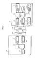
- FIG. 2is a schematic block diagram showing the construction of the master station 101 and the slave station 201 in the information communication system of the present invention.
- FIG. 3is a timing chart for explaining time delays.
- FIG. 4is a timing chart for explaining communication between the master station and the plurality of slave stations in an embodiment of the present invention.
- FIG. 5is a flow chart showing the procedures performed by the control unit 202 of a slave station.
- FIG. 6shows a method for generating time slot numbers and time delay numbers.
- FIG. 7shows the construction of the data transmission detection unit 208 .
- the master station 101allows the memory 105 and the control unit 102 to generate a request signal, allows the modulation unit 103 to modulate the generated request signal by the Amplitude Shift Keying (ASK) modulation or the like, and transmits the modulated request signal to the slave station 201 via the antenna 106 .
- ASKAmplitude Shift Keying
- the contactless IC card as the slave station 201 in this embodimentdoes not contain a battery, and uses as the power source the electromotive force that is generated across the antenna 209 when the antenna receives a radio wave from the master station.
- the present inventioncan be applied to contactless IC cards complying with the ISO14443 or ISO15693 standard, but is not limited to them.
- the demodulation unit 104demodulates the modulated wave received from the slave station via the antenna 106 and passes the demodulated signal to the control unit 102 .
- the control unit 102performs necessary processes based on the information transmitted from the slave station 201 .
- the demodulation unit 204 in the slave stationdemodulates the modulated wave received from the master station 101 via the antenna 209 and passes the demodulated signal to the control unit 202 .
- the control unit 202includes a logic circuit as a main component. This control unit 202 performs various processes including a process for writing/reading data on/from the nonvolatile memory 205 , based on commands and data transmitted from the master station 101 , and generates a response signal to the master station 101 .
- the generated response signalis modulated by the modulation unit 203 by the BPSK modulation method or the like and transmitted to the master station 101 via the antenna 209 .
- the time number generation unit 207allows the control unit 202 to generate time slot numbers and time delay numbers which are used in transmitting the ID of the slave station 201 in response to the ID request signal from the master station 101 .
- FIG. 3is a timing chart for explaining the time delays.
- this embodimentprovides time delays in each time slot.
- the timing with which the ID response signal is transmitted from the slave station 201 to the master station 101is delayed based on the time delay number determined by the time number generation unit 207 of the slave station 201 .
- the delayed timesare obtained by repetitively delaying the ID response signal transmission start timing of the slave station 201 by a certain time period.
- the delayed timesare assigned with numbers called time delay numbers.
- the time number generation unit 207 in the slave station B 401generates a number “2” for both the time slot number and time delay number. Then, after receiving the ID request signal 191 from the master station 101 , the slave station B 401 waits until the time slot 2 , further waits and transmits the ID response signal 491 with the timing of the time delay 2 .
- the slave station C 501generates “2” and “4” for the time slot number and time delay number, respectively, and the slave station D 601 generates “2” and “3”, respectively.
- FIG. 3shows that the slave stations C 501 and D 601 do not transmit response signals in the time slot 2 since the slave station B 401 has already transmitted the ID response signal at the time delay 2 in the time slot 2 .
- the present embodimentat least prevents the case where the master station cannot acquire an ID from any of a plurality of slave stations using the same time slot, by allowing the plurality of slave stations using the same time slot to transmit ID response signals with different timing and exercising a control so that when one of the plurality of slave stations detects that another one of them has already transmitted an ID response signal, the slave station refrains from transmitting an ID response signal.
- the slave stations C 501 and D 601do not transmit the ID response signals since the data transmission detection units 208 of the slave stations C 501 and D 601 detect transmission of the ID response signal by the slave station B 401 .
- time duration ⁇ Td between each delayed timeis set to such a time duration as is enough for the data transmission detection unit 208 to detect that another slave station has transmitted an ID response signal.
- the time duration ⁇ Tdis represented by the following formula: ⁇ Ts>(packet transmission time period)+ ⁇ Td ⁇ N, where ⁇ Ts represents a time period of one time slot, and N the number of delayed times.
- the master station 101receives, as a response to the first ID request signal 191 , the ID response signal 391 from the slave station A 301 and the ID response signal 491 from the slave station B 401 and acquires IDs of these slave stations.
- the slave station B 401no longer needs to transmit an ID response signal in response to the second ID request signal 192 (See FIG. 4 ).
- a probability of occurrence of the overlapping of response signals from slave stationsis reduced. This leads to the reduction in the number of times the master station 101 transmits the ID request signal to the slave stations. This also contributes to the reduction in the processing time of the whole system.
- the slave stations having transmitted an ID response signal in response to the first ID request signaldo not transmit the ID response signal in response to the second ID request signal. Accordingly, no slave station transmits an ID response signal in response to the third ID request signal that is not illustrated in FIG. 4 .
- FIG. 5is a flow chart showing the procedures by the control unit 202 of the slave station 201 .
- the slave station 201When the slave station 201 enters the service area, the slave station 201 powers up under the influence of electric waves from the master station 101 , and the procedure shown in FIG. 5 starts.
- the control unit 202 in the slave station 201awaits a command from the master station 101 (S 101 ).
- the control unit 202judges whether the command is an ID request command or not (S 102 ).
- the control unit 202judges whether the ID expected to be attached to the command agrees with an ID held by the slave station 201 (S 103 ). If they do not agree with each other (S 103 : No), it is judged that the received command is intended for another slave station, then the control returns to the command wait state without performing any process.
- the control unit 202performs the process designated by the command (S 104 ).
- the procedure explained so farenables the master station to separately handle processes requested by a plurality of slave stations in the service area.
- the time number generation unit 207If the received command is an ID request command (S 102 : Yes), the time number generation unit 207 generates a time slot number (S 105 ) and a time delay number (S 106 ).
- time slot numbers and time delay numbers(hereafter, in generalization, they are referred to as time numbers) are generated will be described.
- FIG. 6shows the method for generating the time numbers.
- each slave stationgenerates the time numbers using the ID of each slave station.
- the main reason for thisis that the use of the ID, which is uniquely assigned, is considered to be the preferable way to prevent a plurality of slave stations from generating the same time number so as to prevent the occurrence of overlapping response signals from the slave stations.
- IDs T 1 “00230167” and T 7 “00230168”are assigned to the slave stations A 301 and B 401 , respectively.
- time slot numbersare generated using upper four digits, that is “0023” (T 2 and T 8 ) of the IDs T 1 and T 7 , for both slave station A 301 and B 401 .
- time delay numbersare generated using lower four digits of IDs, that is “0167” (T 3 ) for the slave station A 301 and “0168” (T 9 ) for the slave station B 401 .
- time slot numbers (T 5 and T 11 ) and time delay numbers (T 6 and T 12 )are generated, respectively.
- the same time slot number “2” (T 5 and T 11 )is generated since the upper four digits of the two IDs are both “0023”, but the probability that the same time delay number is generated is very low since the two IDs have different sets of lower four digits.
- different time delay numbersare generated (“2” for slave station A 301 , represented as T 6 , and “4” for slave station B 401 , represented as T 12 ). Accordingly, the probability that the same time slot number and the same time delay number are generated is very low. As a result, even if the same time slot number is generated, it is highly possible that different time delay numbers are generated. This prevents the occurrence of overlapping ID response signals transmitted from a plurality of slave stations.
- the method for generating time numbersis not limited to the above-described one including the use of slave station IDs.
- a variety of methodscan be applicable.
- a plurality of slave stationsgenerate the same time number in response to the first ID request signal. So, it is preferable that each slave station generates, in response to the second ID request signal and onwards, a time number different from the previously generated one.
- the following methodsare applicable: (a) a method of using a random number generation circuit provided in the time number generation unit 207 ; and (b) a combination of a method of generating a time number by assigning a different weight to each bit and a method of shifting bits of an input ID.
- the transmission timing of the ID response signalis controlled based on the generated time numbers.
- the value corresponding to the generated time slot numberis set in the timer 206 (S 107 ), and the control unit 202 waits until the time reaches the start time of the determined time slot (S 108 ).
- the control unit 202When the time reaches the start time of the determined time slot (S 108 : Yes), the value corresponding to the generated time delay number is set in the timer 206 (S 109 ). Then, if the data transmission detection unit 208 detects that another slave station has transmitted an ID response signal (S 110 : Yes), the control unit 202 returns to the command wait state without performing a process.
- the control unit 202transmits an ID response signal containing the ID of the slave station 201 (S 112 ). The control returns to the command wait state. In this way, the overlapping of a plurality of response signals from slave stations is prevented by allowing each slave station to check whether another slave station has transmitted an ID response signal in the same slot, and if it detects the transmission, return to the command wait state without transmitting an ID response signal.
- FIG. 7shows the detailed construction of the data transmission detection unit 208 . This figure also shows portions of the master station 101 including the antenna 106 , and the slave stations A 301 and B 401 .
- the slave station A 301transmits a signal to the master station 101 by inputting a modulated response signal into a transistor (not illustrated) provided in the modulation unit 203 a whose source and drain are respectively connected to the ends of the antenna 209 a , allowing a load fluctuation to be generated.
- the slave station B 401transmits a signal by inputting a modulated response signal in to a transistor provided in the modulation unit 203 b.
- the slave station B 401detects a signal fluctuation that is input to the level comparator 210 b via a signal line. Then, the level comparator 210 b judges whether the detected signal fluctuation is a small signal fluctuation due to noise or the like, or a relatively large fluctuation due to transmission of the ID response signal by another slave station. The detection result is transmitted to the control unit 202 b as a data transmission detection signal 211 b.
- the level comparator 210 b in the slave station B 401judges that the detected fluctuation is a relatively large fluctuation due to transmission of the response signal by another slave station.
- the detection result transmitted to the control unit 202 bprevents the slave station B 401 from transmitting a response signal to the master station.
- the control unit 202can recognize that it does not indicate a response signal transmission by another slave station since the control unit 202 knows the slave station A 301 is transmitting a response signal. In this way, when a slave station transmits a response signal, the other slave stations can detect it and do not transmit a response signal.
- each slave stationdetermines the time delay number when transmitting an ID response signal in response to an ID request signal transmitted by the master station.
- the determination of a time delay numbermay be done with other timing.
- the time delay numbersmay be used in the case that the master station requests all of the slave stations to write data on the memory therein.
- the master stationtransmits a command not including IDs of the slave stations, and all of the slave stations transmit their response signal (e.g., a signal showing the result of data writing) using time delay.
- each slave stationis controlled so as not to transmit its response signal when the slave station detects that another slave station has transmitted a response signal, whereby overlapping among response signals from a plurality of slave stations can be avoided.
- the master stationacquires IDs from the slave station, it is possible that the master station performs a certain operation. That is, the above embodiment deals with the case where communication between the master station and each of the slave stations is conducted at the single frequency band of, for example, 13.56 MHz. Therefore, if the plurality of slave stations transmit their response signals all at once, the master station cannot recognize the ID of each slave station.
- each slave stationhas only to determine the time delay number to delay the transmission timing of the response signal.
- the above embodimentdeals with the case where the number of time slots and time delays are respectively 4 and 5 . However, neither time slot numbers nor time delay numbers are limited to these numbers, but they can be freely selected.
- the above-mentioned circuit elements in each slave stationi.e., the circuit including the control unit 202 , the timer 206 , the time number generation unit 207 , the data transmission detection unit 208 or the like
- the IC chipis not limited to the above-mentioned IC card, but can be variously processed for practical applications such as a label attached on the mail and a contactless tag attached to a baggage.
Landscapes
- Engineering & Computer Science (AREA)
- Physics & Mathematics (AREA)
- Theoretical Computer Science (AREA)
- General Physics & Mathematics (AREA)
- Computer Vision & Pattern Recognition (AREA)
- Artificial Intelligence (AREA)
- Toxicology (AREA)
- Health & Medical Sciences (AREA)
- Computer Networks & Wireless Communication (AREA)
- Electromagnetism (AREA)
- General Health & Medical Sciences (AREA)
- Computer Hardware Design (AREA)
- Microelectronics & Electronic Packaging (AREA)
- Mobile Radio Communication Systems (AREA)
- Time-Division Multiplex Systems (AREA)
- Telephone Function (AREA)
- Near-Field Transmission Systems (AREA)
Abstract
Description
ΔTs>(packet transmission time period)+ΔTd×N,
where ΔTs represents a time period of one time slot, and N the number of delayed times. Thus, compared with the method of increasing the number of time slots, the present method of using the delayed times reduces the system processing time.
(2) In the above-mentioned embodiment, each slave station is controlled so as not to transmit its response signal when the slave station detects that another slave station has transmitted a response signal, whereby overlapping among response signals from a plurality of slave stations can be avoided. However, from the point of view that the master station acquires IDs from the slave station, it is possible that the master station performs a certain operation. That is, the above embodiment deals with the case where communication between the master station and each of the slave stations is conducted at the single frequency band of, for example, 13.56 MHz. Therefore, if the plurality of slave stations transmit their response signals all at once, the master station cannot recognize the ID of each slave station. However, communication at a plurality of frequency bands can eliminate the necessity of detecting the response signals from slave stations, where each slave station has only to determine the time delay number to delay the transmission timing of the response signal.
(3) The above embodiment deals with the case where the number of time slots and time delays are respectively4 and5. However, neither time slot numbers nor time delay numbers are limited to these numbers, but they can be freely selected.
(4) The above-mentioned circuit elements in each slave station (i.e., the circuit including the
Claims (10)
ΔTs>(packet transmission time period)+ΔTd×N,
ΔTs>(packet transmission time period)+ΔTd×N,
ΔTs>(packet transmission time period)+ΔTd×N,
Applications Claiming Priority (2)
| Application Number | Priority Date | Filing Date | Title |
|---|---|---|---|
| JP31342299AJP2001136100A (en) | 1999-11-04 | 1999-11-04 | Information communication processing system |
| PCT/JP2000/007721WO2001033725A1 (en) | 1999-11-04 | 2000-11-02 | Information communication system, noncontact ic card, and ic chip |
Publications (1)
| Publication Number | Publication Date |
|---|---|
| US7187692B1true US7187692B1 (en) | 2007-03-06 |
Family
ID=18041117
Family Applications (1)
| Application Number | Title | Priority Date | Filing Date |
|---|---|---|---|
| US10/111,985Expired - Fee RelatedUS7187692B1 (en) | 1999-11-04 | 2000-11-02 | Information communication system, noncontact IC card, and IC chip |
Country Status (5)
| Country | Link |
|---|---|
| US (1) | US7187692B1 (en) |
| EP (1) | EP1233531A4 (en) |
| JP (1) | JP2001136100A (en) |
| CN (1) | CN1175588C (en) |
| WO (1) | WO2001033725A1 (en) |
Cited By (5)
| Publication number | Priority date | Publication date | Assignee | Title |
|---|---|---|---|---|
| WO2010007540A1 (en)* | 2008-07-17 | 2010-01-21 | Ipico South Africa (Pty) Limited | Rfid transmission protocol and method of operating a transponder |
| DE102011003659A1 (en)* | 2011-02-04 | 2012-08-09 | MESH Mobile Electronics in Sports & Health GmbH | Method for forming group from multiple participants to transmission channel, involves determining participant as master which sends master frame with predetermined number of idle slots |
| US8698602B2 (en) | 2002-09-11 | 2014-04-15 | Nxp B.V. | Method of reading a plurality of non-contact data carriers, including an anti-collision scheme |
| US20160037519A1 (en)* | 2003-05-07 | 2016-02-04 | Sony Corporation | Wireless communication system, wireless communication apparatus, wireless communication method, and computer program |
| EP3107042A1 (en)* | 2015-06-16 | 2016-12-21 | Motorola Mobility LLC | Person-centric activation of radio frequency identification (rfid) tag |
Families Citing this family (12)
| Publication number | Priority date | Publication date | Assignee | Title |
|---|---|---|---|---|
| DE60217194T2 (en)* | 2001-11-20 | 2007-10-04 | Matsushita Electric Industrial Co., Ltd., Kadoma | Contactless chip card, response method and corresponding program |
| DE10227558A1 (en)* | 2002-06-20 | 2004-01-15 | Infineon Technologies Ag | System for data exchange between at least two contactless data carriers |
| DE10254151A1 (en)* | 2002-11-20 | 2004-06-17 | Siemens Ag | Method for collision-free data transmission between read / write devices (SLG) and a mobile data memory (MDS) as well as read / write devices (SLG), mobile data memory (MDS) and identification system for such a method |
| JP4023308B2 (en)* | 2002-12-17 | 2007-12-19 | ソニー株式会社 | Communication apparatus and communication method |
| KR20060121230A (en)* | 2003-12-23 | 2006-11-28 | 코닌클리즈케 필립스 일렉트로닉스 엔.브이. | Determination of disconnect time information, integrated circuit and data carrier |
| JP4072503B2 (en)* | 2004-02-04 | 2008-04-09 | シャープ株式会社 | IC card with built-in coprocessor for auxiliary operation and control method thereof |
| US7257504B2 (en)* | 2005-06-03 | 2007-08-14 | Tagent Corporation | Production of radio frequency ID tags |
| US7958291B2 (en) | 2006-10-10 | 2011-06-07 | Atmel Rousset S.A.S. | Supplemental communication interface |
| US7845568B2 (en)* | 2007-05-09 | 2010-12-07 | Atmel Rousset S.A.S. | Managing power and timing in a smart card device |
| US9213872B2 (en) | 2010-02-18 | 2015-12-15 | Nokia Technologies Oy | Method and apparatus for discrimination of RFID tags |
| JP6582477B2 (en)* | 2014-11-28 | 2019-10-02 | カシオ計算機株式会社 | Wireless communication apparatus, wireless communication method and program |
| CN114234922B (en)* | 2021-12-30 | 2025-02-07 | 国网黑龙江省电力有限公司鸡西供电公司 | Tower Online Monitoring System |
Citations (20)
| Publication number | Priority date | Publication date | Assignee | Title |
|---|---|---|---|---|
| US4471345A (en) | 1982-03-05 | 1984-09-11 | Sensormatic Electronics Corporation | Randomized tag to portal communication system |
| JPS639249A (en) | 1986-06-30 | 1988-01-14 | Nippon Telegr & Teleph Corp <Ntt> | System control method |
| US4750171A (en)* | 1986-07-11 | 1988-06-07 | Tadiran Electronics Industries Ltd. | Data switching system and method |
| US5119373A (en)* | 1990-02-09 | 1992-06-02 | Luxcom, Inc. | Multiple buffer time division multiplexing ring |
| JPH05300166A (en) | 1992-04-22 | 1993-11-12 | Nippon Telegr & Teleph Corp <Ntt> | Burst signal multiplex control system |
| JPH07143142A (en) | 1993-06-17 | 1995-06-02 | Nissin Electric Co Ltd | Data communication system |
| US5481541A (en)* | 1991-09-07 | 1996-01-02 | Motorola, Inc. | Method of operation of remote data/control apparatus with controlled response timing |
| JPH0869583A (en) | 1994-08-26 | 1996-03-12 | Tec Corp | Moving body discriminating method |
| JPH08223081A (en) | 1995-02-20 | 1996-08-30 | Fuji Electric Co Ltd | Response control method for mobile identification device |
| DE19526353A1 (en) | 1995-07-19 | 1997-01-23 | Anatoli Stobbe | Process for the automatic identification of an unknown number of transponders by a reader and identification system for carrying out the process |
| US5680459A (en) | 1994-04-29 | 1997-10-21 | Kasten Chase Applied Research Limited | Passive transponder |
| US5698837A (en)* | 1994-10-28 | 1997-12-16 | Mitsubishi Denki Kabushiki Kaisha | Method and system for identifying and communicating with a plurality of contactless IC cards |
| US5777561A (en) | 1996-09-30 | 1998-07-07 | International Business Machines Corporation | Method of grouping RF transponders |
| JPH113407A (en) | 1997-06-13 | 1999-01-06 | Omron Corp | Communication system and device |
| JPH11134468A (en) | 1997-10-29 | 1999-05-21 | Oizumi Corp | Medal counter |
| USRE36353E (en)* | 1993-06-30 | 1999-10-26 | Cabletron Systems, Inc. | Methods and apparatus for use in a network of the ethernet type, to improve fairness by controlling collision backoff times and using stopped backoff timing in the event of channel capture |
| EP1017005A2 (en) | 1998-12-01 | 2000-07-05 | Integrated Sensor Solutions | A system and method for communicating with multiple transponders |
| US6388562B1 (en)* | 1998-01-12 | 2002-05-14 | Denso Corporation | Contactless IC card communication system and related method |
| US6456191B1 (en)* | 1999-03-23 | 2002-09-24 | Exi Wireless Systems Inc. | Tag system with anti-collision features |
| US6954438B2 (en)* | 2001-02-21 | 2005-10-11 | 3Com Corporation | Wireless callback access control for a LAN network access point |
Family Cites Families (1)
| Publication number | Priority date | Publication date | Assignee | Title |
|---|---|---|---|---|
| JPH11134458A (en)* | 1997-10-30 | 1999-05-21 | Hitachi Chem Co Ltd | Ic card |
- 1999
- 1999-11-04JPJP31342299Apatent/JP2001136100A/enactivePending
- 2000
- 2000-11-02USUS10/111,985patent/US7187692B1/ennot_activeExpired - Fee Related
- 2000-11-02EPEP00971742Apatent/EP1233531A4/ennot_activeWithdrawn
- 2000-11-02WOPCT/JP2000/007721patent/WO2001033725A1/ennot_activeApplication Discontinuation
- 2000-11-02CNCNB00817797XApatent/CN1175588C/ennot_activeExpired - Fee Related
Patent Citations (20)
| Publication number | Priority date | Publication date | Assignee | Title |
|---|---|---|---|---|
| US4471345A (en) | 1982-03-05 | 1984-09-11 | Sensormatic Electronics Corporation | Randomized tag to portal communication system |
| JPS639249A (en) | 1986-06-30 | 1988-01-14 | Nippon Telegr & Teleph Corp <Ntt> | System control method |
| US4750171A (en)* | 1986-07-11 | 1988-06-07 | Tadiran Electronics Industries Ltd. | Data switching system and method |
| US5119373A (en)* | 1990-02-09 | 1992-06-02 | Luxcom, Inc. | Multiple buffer time division multiplexing ring |
| US5481541A (en)* | 1991-09-07 | 1996-01-02 | Motorola, Inc. | Method of operation of remote data/control apparatus with controlled response timing |
| JPH05300166A (en) | 1992-04-22 | 1993-11-12 | Nippon Telegr & Teleph Corp <Ntt> | Burst signal multiplex control system |
| JPH07143142A (en) | 1993-06-17 | 1995-06-02 | Nissin Electric Co Ltd | Data communication system |
| USRE36353E (en)* | 1993-06-30 | 1999-10-26 | Cabletron Systems, Inc. | Methods and apparatus for use in a network of the ethernet type, to improve fairness by controlling collision backoff times and using stopped backoff timing in the event of channel capture |
| US5680459A (en) | 1994-04-29 | 1997-10-21 | Kasten Chase Applied Research Limited | Passive transponder |
| JPH0869583A (en) | 1994-08-26 | 1996-03-12 | Tec Corp | Moving body discriminating method |
| US5698837A (en)* | 1994-10-28 | 1997-12-16 | Mitsubishi Denki Kabushiki Kaisha | Method and system for identifying and communicating with a plurality of contactless IC cards |
| JPH08223081A (en) | 1995-02-20 | 1996-08-30 | Fuji Electric Co Ltd | Response control method for mobile identification device |
| DE19526353A1 (en) | 1995-07-19 | 1997-01-23 | Anatoli Stobbe | Process for the automatic identification of an unknown number of transponders by a reader and identification system for carrying out the process |
| US5777561A (en) | 1996-09-30 | 1998-07-07 | International Business Machines Corporation | Method of grouping RF transponders |
| JPH113407A (en) | 1997-06-13 | 1999-01-06 | Omron Corp | Communication system and device |
| JPH11134468A (en) | 1997-10-29 | 1999-05-21 | Oizumi Corp | Medal counter |
| US6388562B1 (en)* | 1998-01-12 | 2002-05-14 | Denso Corporation | Contactless IC card communication system and related method |
| EP1017005A2 (en) | 1998-12-01 | 2000-07-05 | Integrated Sensor Solutions | A system and method for communicating with multiple transponders |
| US6456191B1 (en)* | 1999-03-23 | 2002-09-24 | Exi Wireless Systems Inc. | Tag system with anti-collision features |
| US6954438B2 (en)* | 2001-02-21 | 2005-10-11 | 3Com Corporation | Wireless callback access control for a LAN network access point |
Non-Patent Citations (1)
| Title |
|---|
| Phillips Semiconductors: "Short Form Specification: SmartMX" Integrated Circuits: P5CTO72 Secure Triple Interface Smart Card Controller, Online! No. Rev. 1.0, May 23, 2003. |
Cited By (11)
| Publication number | Priority date | Publication date | Assignee | Title |
|---|---|---|---|---|
| US8698602B2 (en) | 2002-09-11 | 2014-04-15 | Nxp B.V. | Method of reading a plurality of non-contact data carriers, including an anti-collision scheme |
| US8994507B2 (en) | 2002-09-11 | 2015-03-31 | Nxp B.V. | Non-contact data carriers including an anti-collision scheme |
| US20150205982A1 (en)* | 2002-09-11 | 2015-07-23 | Nxp B.V. | Non-contact data carriers including an anti-collision scheme |
| US9875380B2 (en)* | 2002-09-11 | 2018-01-23 | Nxp B.V. | Non-contact data carriers including an anti-collision scheme |
| US20160037519A1 (en)* | 2003-05-07 | 2016-02-04 | Sony Corporation | Wireless communication system, wireless communication apparatus, wireless communication method, and computer program |
| US9622271B2 (en)* | 2003-05-07 | 2017-04-11 | Sony Corporation | Wireless communication system, wireless communication apparatus, wireless communication method, and computer program |
| US10897762B2 (en) | 2003-05-07 | 2021-01-19 | Sony Corporation | Wireless communication system, wireless communication apparatus, wireless communication method, and computer program |
| WO2010007540A1 (en)* | 2008-07-17 | 2010-01-21 | Ipico South Africa (Pty) Limited | Rfid transmission protocol and method of operating a transponder |
| DE102011003659A1 (en)* | 2011-02-04 | 2012-08-09 | MESH Mobile Electronics in Sports & Health GmbH | Method for forming group from multiple participants to transmission channel, involves determining participant as master which sends master frame with predetermined number of idle slots |
| EP3107042A1 (en)* | 2015-06-16 | 2016-12-21 | Motorola Mobility LLC | Person-centric activation of radio frequency identification (rfid) tag |
| US9965658B2 (en) | 2015-06-16 | 2018-05-08 | Motorola Mobility Llc | Person-centric activation of radio frequency identification (RFID) tag |
Also Published As
| Publication number | Publication date |
|---|---|
| CN1175588C (en) | 2004-11-10 |
| JP2001136100A (en) | 2001-05-18 |
| EP1233531A4 (en) | 2004-11-03 |
| EP1233531A1 (en) | 2002-08-21 |
| CN1413389A (en) | 2003-04-23 |
| WO2001033725A1 (en) | 2001-05-10 |
Similar Documents
| Publication | Publication Date | Title |
|---|---|---|
| US7187692B1 (en) | Information communication system, noncontact IC card, and IC chip | |
| CA2190546C (en) | Enhanced uplink modulated backscatter system | |
| JP4709895B2 (en) | Non-contact type IC card for data communication using multiple protocols and communication method therefor | |
| US7026935B2 (en) | Method and apparatus to configure an RFID system to be adaptable to a plurality of environmental conditions | |
| US5345231A (en) | Contactless inductive data-transmission system | |
| US8643470B2 (en) | Semiconductor integrated circuit, IC card mounted with the semiconductor integrated circuit, and operation method for the same | |
| US7230943B2 (en) | Wireless information processing system with wireless information recording medium and wireless information processing apparatus, and communication method therefor | |
| US20040116074A1 (en) | Communication apparatus and communication method | |
| US7703690B2 (en) | Non-contact IC apparatus and control method | |
| US20020024421A1 (en) | Apparatus and method for preventing data collision in a radio frequency identification tag system | |
| US7309018B2 (en) | Semiconductor integrated circuit device and noncontact IC card | |
| US20070138277A1 (en) | Information access system and method for accessing information in contactless information storage devices | |
| US7308249B2 (en) | Communication between electromagnetic transponders | |
| JP2001092930A (en) | Reader / writer and contactless IC card system | |
| US6886752B2 (en) | Portable electronic apparatus, IC card and reader/writer | |
| JPH11120307A (en) | Communication equipment | |
| US7252241B2 (en) | Data communication system, data communication device, contactless communication medium, and communication device control program | |
| JP4352326B2 (en) | Reception device and semiconductor integrated circuit | |
| JPH08167090A (en) | Mobile identification method | |
| JP2009009187A (en) | Information processor and data processing method | |
| JP2001358609A (en) | Interrogator | |
| JPH11219414A (en) | Mobile information communication object | |
| JPH06103420A (en) | Non-contact ic card type gate device |
Legal Events
| Date | Code | Title | Description |
|---|---|---|---|
| AS | Assignment | Owner name:MATSUSHITA ELECTRIC INDUSTRIAL CO., LTD., JAPAN Free format text:ASSIGNMENT OF ASSIGNORS INTEREST;ASSIGNORS:OOYA, MITSUYOSHI;TOKUMITSU, SHINICHI;REEL/FRAME:014886/0384 Effective date:20020515 | |
| FEPP | Fee payment procedure | Free format text:PAYOR NUMBER ASSIGNED (ORIGINAL EVENT CODE: ASPN); ENTITY STATUS OF PATENT OWNER: LARGE ENTITY | |
| STCF | Information on status: patent grant | Free format text:PATENTED CASE | |
| FPAY | Fee payment | Year of fee payment:4 | |
| AS | Assignment | Owner name:PANASONIC CORPORATION, JAPAN Free format text:CHANGE OF NAME;ASSIGNOR:MATSUSHITA ELECTRIC INDUSTRIAL CO., LTD.;REEL/FRAME:031947/0358 Effective date:20081001 | |
| AS | Assignment | Owner name:PANASONIC CORPORATION, JAPAN Free format text:LIEN;ASSIGNOR:COLLABO INNOVATIONS, INC.;REEL/FRAME:031997/0445 Effective date:20131213 | |
| AS | Assignment | Owner name:COLLABO INNOVATIONS, INC., CANADA Free format text:ASSIGNMENT OF ASSIGNORS INTEREST;ASSIGNOR:PANASONIC CORPORATION;REEL/FRAME:033021/0806 Effective date:20131212 | |
| FPAY | Fee payment | Year of fee payment:8 | |
| FEPP | Fee payment procedure | Free format text:MAINTENANCE FEE REMINDER MAILED (ORIGINAL EVENT CODE: REM.); ENTITY STATUS OF PATENT OWNER: LARGE ENTITY | |
| LAPS | Lapse for failure to pay maintenance fees | Free format text:PATENT EXPIRED FOR FAILURE TO PAY MAINTENANCE FEES (ORIGINAL EVENT CODE: EXP.); ENTITY STATUS OF PATENT OWNER: LARGE ENTITY | |
| STCH | Information on status: patent discontinuation | Free format text:PATENT EXPIRED DUE TO NONPAYMENT OF MAINTENANCE FEES UNDER 37 CFR 1.362 | |
| FP | Lapsed due to failure to pay maintenance fee | Effective date:20190306 |