US7187293B2 - Singulation of radio frequency identification (RFID) tags for testing and/or programming - Google Patents
Singulation of radio frequency identification (RFID) tags for testing and/or programmingDownload PDFInfo
- Publication number
- US7187293B2 US7187293B2US11/205,026US20502605AUS7187293B2US 7187293 B2US7187293 B2US 7187293B2US 20502605 AUS20502605 AUS 20502605AUS 7187293 B2US7187293 B2US 7187293B2
- Authority
- US
- United States
- Prior art keywords
- tags
- tag
- rfid
- web
- signal
- Prior art date
- Legal status (The legal status is an assumption and is not a legal conclusion. Google has not performed a legal analysis and makes no representation as to the accuracy of the status listed.)
- Expired - Lifetime
Links
Images


Classifications
- G—PHYSICS
- G01—MEASURING; TESTING
- G01R—MEASURING ELECTRIC VARIABLES; MEASURING MAGNETIC VARIABLES
- G01R31/00—Arrangements for testing electric properties; Arrangements for locating electric faults; Arrangements for electrical testing characterised by what is being tested not provided for elsewhere
- G01R31/28—Testing of electronic circuits, e.g. by signal tracer
- G01R31/282—Testing of electronic circuits specially adapted for particular applications not provided for elsewhere
- G01R31/2822—Testing of electronic circuits specially adapted for particular applications not provided for elsewhere of microwave or radiofrequency circuits
- G—PHYSICS
- G06—COMPUTING OR CALCULATING; COUNTING
- G06K—GRAPHICAL DATA READING; PRESENTATION OF DATA; RECORD CARRIERS; HANDLING RECORD CARRIERS
- G06K19/00—Record carriers for use with machines and with at least a part designed to carry digital markings
- G06K19/06—Record carriers for use with machines and with at least a part designed to carry digital markings characterised by the kind of the digital marking, e.g. shape, nature, code
- G06K19/067—Record carriers with conductive marks, printed circuits or semiconductor circuit elements, e.g. credit or identity cards also with resonating or responding marks without active components
- G06K19/07—Record carriers with conductive marks, printed circuits or semiconductor circuit elements, e.g. credit or identity cards also with resonating or responding marks without active components with integrated circuit chips
- G06K19/077—Constructional details, e.g. mounting of circuits in the carrier
- G06K19/07718—Constructional details, e.g. mounting of circuits in the carrier the record carrier being manufactured in a continuous process, e.g. using endless rolls
- G—PHYSICS
- G06—COMPUTING OR CALCULATING; COUNTING
- G06K—GRAPHICAL DATA READING; PRESENTATION OF DATA; RECORD CARRIERS; HANDLING RECORD CARRIERS
- G06K19/00—Record carriers for use with machines and with at least a part designed to carry digital markings
- G06K19/06—Record carriers for use with machines and with at least a part designed to carry digital markings characterised by the kind of the digital marking, e.g. shape, nature, code
- G06K19/067—Record carriers with conductive marks, printed circuits or semiconductor circuit elements, e.g. credit or identity cards also with resonating or responding marks without active components
- G06K19/07—Record carriers with conductive marks, printed circuits or semiconductor circuit elements, e.g. credit or identity cards also with resonating or responding marks without active components with integrated circuit chips
- G06K19/077—Constructional details, e.g. mounting of circuits in the carrier
- G06K19/07749—Constructional details, e.g. mounting of circuits in the carrier the record carrier being capable of non-contact communication, e.g. constructional details of the antenna of a non-contact smart card
- G—PHYSICS
- G06—COMPUTING OR CALCULATING; COUNTING
- G06K—GRAPHICAL DATA READING; PRESENTATION OF DATA; RECORD CARRIERS; HANDLING RECORD CARRIERS
- G06K7/00—Methods or arrangements for sensing record carriers, e.g. for reading patterns
- G06K7/0008—General problems related to the reading of electronic memory record carriers, independent of its reading method, e.g. power transfer
- G—PHYSICS
- G06—COMPUTING OR CALCULATING; COUNTING
- G06K—GRAPHICAL DATA READING; PRESENTATION OF DATA; RECORD CARRIERS; HANDLING RECORD CARRIERS
- G06K7/00—Methods or arrangements for sensing record carriers, e.g. for reading patterns
- G06K7/0095—Testing the sensing arrangement, e.g. testing if a magnetic card reader, bar code reader, RFID interrogator or smart card reader functions properly
- G—PHYSICS
- G06—COMPUTING OR CALCULATING; COUNTING
- G06K—GRAPHICAL DATA READING; PRESENTATION OF DATA; RECORD CARRIERS; HANDLING RECORD CARRIERS
- G06K7/00—Methods or arrangements for sensing record carriers, e.g. for reading patterns
- G06K7/10—Methods or arrangements for sensing record carriers, e.g. for reading patterns by electromagnetic radiation, e.g. optical sensing; by corpuscular radiation
- G06K7/10009—Methods or arrangements for sensing record carriers, e.g. for reading patterns by electromagnetic radiation, e.g. optical sensing; by corpuscular radiation sensing by radiation using wavelengths larger than 0.1 mm, e.g. radio-waves or microwaves
- G06K7/10366—Methods or arrangements for sensing record carriers, e.g. for reading patterns by electromagnetic radiation, e.g. optical sensing; by corpuscular radiation sensing by radiation using wavelengths larger than 0.1 mm, e.g. radio-waves or microwaves the interrogation device being adapted for miscellaneous applications
- G06K7/10465—Methods or arrangements for sensing record carriers, e.g. for reading patterns by electromagnetic radiation, e.g. optical sensing; by corpuscular radiation sensing by radiation using wavelengths larger than 0.1 mm, e.g. radio-waves or microwaves the interrogation device being adapted for miscellaneous applications the interrogation device being capable of self-diagnosis, e.g. in addition to or as part of the actual interrogation process
Definitions
- the present inventionrelates to high volume testing and programming of radio frequency identification (RFID) tags, including inlays and labels.
- RFIDradio frequency identification
- Radio frequency identification (RFID) tagsare electronic devices that may be affixed to items whose presence is to be detected and/or monitored. The presence of an RFID tag, and therefore the presence of the item to which the tag is affixed, may be checked and monitored by devices known as “readers.” Readers typically transmit radio frequency signals to which the tags respond. Each tag can store a unique identification number. The tags respond to the reader transmitted signals by providing their identification number, bit-by-bit, so that they can be identified.
- RFID tagsare assembled and then laminated to the face sheet of a pressure sensitive laminate. Once laminated, the backside of the RFID tag is coated with an adhesive, and a release liner is applied. After the release liner is applied, the tag is printed and/or die cut into the desired form factor.
- a tagcan be tested either before or after the lamination process. Testing before or after the lamination process is difficult in a web format, where tags are formed in an array of tags in a single sheet of material. When testing tags in a web format, any bad or failed (e.g., non-functional, malfunctioned) tags have to be removed and replaced with good (e.g., functional) tags, which tends to be expensive and time consuming.
- tagsare interacted with by testing the tags and/or programming the tags. According to aspect of the present invention, testing and programming can occur in high volume webs of tags, allowing for improved handling of failed tags.
- RFIDradio frequency identification
- a systemis used to interact with a plurality of RFID tags provided in a roll, web, or any other format.
- the systemsupplies the plurality of tags using a supply spool or other mechanism, and receives the tags with a collection spool or other mechanism.
- a stepper motor or other mechanismcan be used to feed the tags to the collection spool.
- the tagsare fed across a surface, so that the surface is in contact with the tags.
- the surfacehas a first portion and a second portion.
- the first portion of the surfaceis grounded (or coupled to another suitable potential) to inhibit operation of tags that are in contact with the first portion.
- the second portion of the surfacedoes not inhibit operation of tags that are adjacent to the second portion.
- a radio frequency (RF) sourcetransmits a RF signal to interact with a tag adjacent to the second portion of the surface.
- the RF signalmay be a signal for testing the tag and/or a signal for programming the tag.
- the tagscan be moved/advanced to move further tags adjacent to the second portion of the surface so that they may be interacted with.
- FIG. 1shows a block diagram of an exemplary RFID tag, according to an embodiment of the present invention.
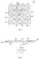
- FIG. 2shows a plan view of an example web of tags.
- FIG. 3shows a plan view of an example grounded surface, according to an embodiment of the present invention.
- FIG. 4shows the web of tags of FIG. 2 in contact with the grounded surface of FIG. 3 , according to an example embodiment of the present invention.
- FIG. 5shows a cross-sectional view of a radio frequency signal interacting with a tag of a web, according to an example embodiment of the present invention.
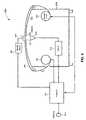
- FIG. 6shows an example of a high volume tester and programmer, according to an embodiment of the present invention.
- FIG. 7shows an example flowchart for interacting with a tags of a web of tags, according to an embodiment of the present invention.
- the present inventionenables the interaction of an RF signal with electronic devices, such as tags fabricated in a roll (i.e., a single tag-width substantially continuous column) or web (i.e., a multi-tag width array of tags that is substantially continuous) of RFID tags.
- electronic devicessuch as tags fabricated in a roll (i.e., a single tag-width substantially continuous column) or web (i.e., a multi-tag width array of tags that is substantially continuous) of RFID tags.
- the interactionmay enable the testing and/or programming of RFID tags, including inlays and labels, such as ultra-high frequency (UHF) tags.
- UHFultra-high frequency
- the present inventionallows for the marking of any failed tags for removal, sorting, disablement, and/or other purposes.
- the description hereinprimarily relates to the testing and programming of RFID tags.
- the inventionis also adaptable to further electronic device types (e.g., electronic devices including one or more IC dies or other electrical components mounted thereto), as would be understood by persons skilled in the relevant art(s) from the teachings herein.
- FIG. 1shows a block diagram of an exemplary RFID tag 100 , according to an embodiment of the present invention.
- RFID tag 100includes a die 104 and related electronics 106 located on a tag substrate 116 .
- Related electronics 106includes an antenna 114 in the present example.
- Die 104can be mounted onto antenna 114 of related electronics 106 , or on other locations of substrate 116 . As is further described elsewhere herein, die 104 may be mounted in either a pads up or pads down orientation.
- RFID tag 100may be located in an area having a large number, population, or pool of RFID tags present.
- Tag 100receives interrogation signals transmitted by one or more tag readers. According to interrogation protocols, tag 100 responds to these signals.
- the response(s) of tag 100includes information that the reader can use to identify the corresponding tag 100 . Once the tag 100 is identified, the existence of tag 100 within a coverage area defined by the tag reader is ascertained.
- RFID tag 100may be used in various applications, such as inventory control, airport baggage monitoring, as well as security and surveillance applications. Thus, tag 100 can be affixed to items such as airline baggage, retail inventory, warehouse inventory, automobiles, compact discs (CDs), digital video discs (DVDs), video tapes, and other objects. Tag 100 enables location monitoring and real time tracking of such items.
- die 104is an integrated circuit that performs RFID operations, such as communicating with one or more tag readers (not shown) according to various interrogation protocols. Exemplary interrogation protocols are described in U.S. Pat. No. 6,002,344 issued Dec. 14, 1999 to Bandy et al., titled “System and Method for Electronic Inventory,” and U.S. patent application Ser. No. 10/072,885, filed on Feb. 12, 2002, both of which are incorporated by reference herein in their entirety. Die 104 includes a plurality of contact pads that each provide an electrical connection with related electronics 106 .
- Related electronics 106are connected to die 104 through a plurality of contact pads of IC die 104 .
- related electronics 106provide one or more capabilities, including RF reception and transmission capabilities, impedance matching, sensor functionality, power reception and storage functionality, as well as additional capabilities.
- the components of related electronics 106can be printed onto a tag substrate 116 with materials, such as conductive inks.
- conductive inksinclude silver conductors 5000, 5021, and 5025, produced by DuPont Electronic Materials of Research Triangle Park, N.C.
- Other example materials or means suitable for printing related electronics 106 onto tag substrate 116include polymeric dielectric composition 5018 and carbon-based PTC resistor paste 7282, which are also produced by DuPont Electronic Materials of Research Triangle Park, N.C.
- Other materials or means that may be used to deposit the component material onto the substratewould be apparent to persons skilled in the relevant art(s) from the teachings herein.
- tag substrate 116has a first surface that accommodates die 104 , related electronics 106 , as well as further components of tag 100 .
- Tag substrate 116also has a second surface that is opposite the first surface.
- An adhesive material and/or backingcan be included on the second surface. When present, an adhesive backing enables tag 100 to be attached to objects, such as books, containers, and consumer products.
- Tag substrate 116is made from a material, such as polyester, paper, plastic, fabrics such as cloth, and/or other materials such as commercially available Tyvec®.
- Embodiments of the present inventionare applicable to all types of tags, including inlays and labels.
- a “tag inlay” or “inlay”is used generally to refer to an assembled RFID device that generally includes a integrated circuit chip and antenna formed on a substrate.
- a “label”is used generally to refer to an inlay that has been attached to a pressure sensitive adhesive (PSA) construction, or laminated and then cut and stacked for application through in-mould, wet glue or heat seal application processes, for example.
- PSApressure sensitive adhesive
- a variety of label typesare contemplated by the present invention.
- a labelincludes an inlay attached to a release liner by pressure sensitive adhesive.
- the release linermay be coated with a low-to-non-stick material, such as silicone, so that it adheres to the pressure sensitive adhesive, but may be easily removed (e.g., by peeling away). After removing the release liner, the label may be attached to a surface of an object, or placed in the object, adhering to the object by the pressure sensitive adhesive.
- a low-to-non-stick materialsuch as silicone
- tag substrate 116can include an indentation, “cavity,” or “cell” (not shown in FIG. 1 ) that accommodates die 104 .
- An example of such an implementationis included in a “pads up” orientation of die 104 .
- FIG. 2shows a plan view of an example web 200 that is a continuous roll type. As shown in FIG. 2 , web 200 may extend further in the directions indicated by arrows 210 and 220 .
- Web 200includes a plurality of tags 100 a–p . In the example of FIG. 2 , the plurality of tags 100 a–p in web 200 is arranged in a plurality of rows and columns. The present invention is applicable to any number of rows and columns of tags, and to other arrangements of tags, in a roll, web, or other format.
- the tagmay processed by a system that interacts with the tag.
- the systemmay test and/or program the tag.
- the tagmay be tested to check for defects in functionality, such as its ability to detect a reader interrogation, and to respond.
- datamay be directly encoded in, or transmitted to the tag (e.g., by a reader), to be stored on the tag.
- the datamay be an identification number for the tag.
- RFID tagsare typically assembled/positioned as close to each other as possible to maximize throughput, thus making the process of reading and testing individual tags difficult. Because of the close spacing, it is very difficult to localize a radiated (e.g., radio frequency) reader field to excite only one tag. Thus, interacting with a specific tag can be difficult. Furthermore, typically, an assembly line must be customized to accommodate the roll or web and the specific type of tags. The testing/programming process becomes even more difficult and expensive considering that RFID tags, for example, come in different forms, sizes and shapes.
- an apparatustests and/or programs a RFID tag in a continuous web of RFID tags, such as in web 200 , by exposing it to a radio frequency (RF) test signal, while nearby RFID tags of the web are isolated from the RF test signal.
- RFradio frequency
- the apparatusaccommodates different types of RFID tags without the need for significant changes to the assembly line.
- FIG. 3shows a plan view of an example contact surface 302 , according to an embodiment of the present invention.
- contact surface 302has a first portion 304 and a second portion 306 .
- First portion 304 of contact surface 302can be made from any electrically conductive material, such as a metal.
- Second portion 306can be an opening through contact surface 302 , or can be spanned by an electrically non-conductive material, such as a sheet of plastic, glass, a polymer, etc.
- FIG. 4shows a plan view of web 200 of FIG. 2 in contact with contact surface 302 , according to an example embodiment of the present invention.
- contact surface 302is not shown, only an outline of second portion 306 is indicated by a dotted line. This is because contact surface 302 is in contact with the opposite side of web 200 , not shown in FIG. 4 , so contact surface 302 is not visible in FIG. 4 .
- web 200is disposed across contact surface 302 so that a large area of web 200 is in contact with contact surface 302 .
- contact surface 302is electrically coupled to an electrical potential, such as a ground potential or other potential, to electrically hold tags of web 200 that are in contact with first portion 304 at the potential.
- tags 100 a–e,g–p in contact with first portion 304are grounded (or held at another potential) by first portion 304 . Because the tags are held at the potential, they are caused to be in a non-operational state. For example, electrically conductive portions of the tags of web 200 , such as their antennas, may be held at the potential due to contact with first portion 304 of contact surface 302 . If the tags are passive tags (i.e., no onboard power source), they cannot receive power from the RF signal, and are thus not operational.
- the potentialmay be generally referred to as a ground potential herein, the potential can be any potential that causes tags coupled thereto to be non-operational (e.g., not able to respond to an RF test and/or programming signal).
- FIG. 5shows a cross-sectional view of a radio frequency signal 502 interacting with tag 100 f of web 200 , according to an example embodiment of the present invention.
- tags 100 b , 100 j , and other tags of web 200are in contact with first portion 304 of contact surface 302 .
- these tagsare inhibited from operation by contact surface 302 .
- tag 100 fis adjacent to second portion 306 of contact surface 302 .
- the operation of tag 100 fis not inhibited, because second portion 306 does not inhibit its operation.
- Tag 100 fcan therefore be interacted with by a RF signal 502 , transmitted by an antenna 506 of a RF signal source 504 , without interference from unwanted responses by other tags 100 of web 200 .
- second portion 306is an opening through contact surface 302 , or an electrically non-conductive material, so does not cause tag 100 f to be inhibited.
- RF signal 502may include a test signal and/or a programming signal.
- RF signal source 504can be a RFID reader, for example.
- RF signal source 504can communicate according to any RFID communication protocol, including those described elsewhere herein, a binary traversal protocol, a slotted aloha protocol, Class 0, Class 1, and EPC Gen 2, for example.
- antenna 506transmits RF signal 502 through contact surface 302 to tag 100 f .
- RF signal 502passes through second portion 306 .
- contact surface 302acts as a RF shield, to shield RF signal 502 from tags 100 b and 100 j .
- second portion 306is an opening or a non-RF shielding material.
- contact surface 302may be a surface of an enclosure.
- the enclosuremay enclose antenna 506 to provide further shielding of RF signal 502 .
- the present inventionaccommodates different types of RFID tags without the need for changes to the assembly line.
- an operator or automated mechanismcan replace contact surface 302 with a second portion 306 of a size to accommodate the different tag size if required.
- contact surface 302may be computer controlled to vary the size of second portion 306 as required, such as through the use of automated shutters, etc., through contact surface 302 . Thus, little to no changes to the assembly line are required.
- FIG. 6shows a view of an example tester and/or programmer 600 for interacting with tags (hereinafter “tester”), according to an embodiment of the present invention.
- tester 600includes a supply spool 602 , a web 604 , a collection spool with stepper motor 606 , an antenna 610 , a reader 612 , a computer 614 , a marking device 616 , a database 618 , a contact surface 620 , and an enclosure 670 .
- tester 600is an automated machine and is controlled by computer 614 .
- One or more elements of tester 600can be enclosed by enclosure 670 .
- reader 612 , antenna 610 , supply spool 602 , and stepper motor 606are enclosed by enclosure 670 .
- enclosure 670is a cabinet made from an electromagnetic signal shielding material, such as a metal, and/or is made from other materials.
- human interventionmay be used to set up tester 600 .
- an operatoridentifies a roll or web of RFID tags to be tested or programmed, and loads tester 600 with a supply spool 602 containing the identified web (or roll).
- Computer 614communicates with database 618 for information regarding the tags of the identified web.
- Database 618uploads information such as testing and programming specifications, tag physical characteristics, and/or other information related to the testing and programming of tags (such as inlays or labels) to computer 614 . Although shown separately in FIG. 6 , database 618 can be maintained in computer 614 .
- RFID tagsenter the testing and/or programming phase in the continuous web form of web 604 contained on supply spool 602 .
- web 604may be supplied in the form of discrete rectangular sheets of tags, or in other forms.
- Supply spool 602supplies web 604 to tester 600 for testing and/or programming.
- Web 604is moved across contact surface 620 and across an ungrounded area 622 of contact surface 620 to collection spool 606 .
- Contact surface 620provides an electrical ground (or other suitable potential) contact to ground the portion of the RFID articles of web 604 in contact with contact surface 620 .
- ungrounded portion 622is an example of second portion 306 of FIG. 3
- the remainder of contact surface 620is an example of first portion 304 of FIG. 3 .
- contact surface 620is a planar or curved metal shield, but can have shapes and configurations.
- contact surface 620may be a portion of enclosure 670 , such as a top portion of enclosure 670 , as shown in FIG. 6 , configured similarly to a cabinet or table.
- contact surface 620may comprise at least one metal clamp or other grounding instrument that clamps on a portion of web 604 where electrical grounding is desired.
- contact surface 620is a conveyor belt with metal contact regions for grounding tags in contact with the contact regions.
- various other techniques known in the artcan be used to electrically ground materials of web 604 .
- a portion 624 of web 604is desired to be tested and/or programmed.
- Web portion 624is positioned adjacent to ungrounded portion 622 of contact surface 620 to be tested and/or programmed.
- Web portion 624comprises one or more tags, depending upon the configuration of the ungrounded area 622 and on the testing and programming specifications.
- Web portion 624is not grounded (due to ungrounded portion 622 of contact surface 620 ), and thus can be interacted with.
- ungrounded area 622is an opening 626 over which web 604 traverses.
- web portion 624is freed from contact with ground, thereby allowing it to be tested and/or programmed by a RF field.
- opening 626can be variably adjusted in size and/or shape to accommodate different types of RFID articles to be tested.
- the adaptability of the size and/or shape of opening 626allows tester 600 to be adaptable, thus eliminating the need for specific dies or testing machines for a particular RFID article.
- the adaptability of opening 626allows for more accurate control of the exposure of the RF field to web portion 624 . This minimizes or eliminates the effect on adjacent tags of web 604 .
- ungrounded area 622includes a structure made of an electrically nonconductive material.
- web 604is supported or held by the material of ungrounded area 622 .
- the contact surface 620is a metal shield, then part of the metal shield over which web 604 traverses can be made of an electrically nonconductive material, thereby creating an ungrounded portion of web 604 .
- the ungrounded areamay include a clamp made of nonconductive material, or is another mechanism or instrument for decoupling web portion 624 from ground.
- ungrounded area 622may include a non-electrically conductive wheel or bump, etc., to raise web portion 624 from contact with contact surface 620 .
- the testing and/or programmingis accomplished by exposure to a RF field.
- Antenna 610emits an RF signal generated by reader 612 .
- Reader 612can be a conventional tag reader, or can be a reader designed for use in a tag test and/or programming environment. The characteristics of the RF field are controlled by reader 612 , which is controlled by computer 614 .
- antenna 610is located on the opposite side of contact surface 620 from which web 604 is located. In such a configuration, contact surface 620 acts both as a grounding mechanism and as a RF shield for web 604 . However, in alternative embodiments, antenna 610 can be located elsewhere, including on the same size of contact surface 620 as web 604 .
- tester 600includes marking device 616 to mark a tag on web 604 for later identification. Once a tag is marked, it can be identified for sorting, removal, retesting, recycling, or any other purpose. Marking device 616 is controlled by computer 614 . In an embodiment, computer 614 tracks a tag to be marked as it is moved with web through tester 600 . This allows for flexibility in placing marking device 616 at or downstream from the testing and/or programming stage while maintaining the location of the tag to be marked.
- the marking device 616is a residue depositing device that deposits an ink, paint, or any other staining or marking material.
- the marking device 616is a punching device. Such punching device may punch a hole partially or wholly through the tag being marked, including making an indentation in the tag.
- FIG. 7shows an example flowchart 700 for interacting with a tags of a web of tags, according to an embodiment of the present invention.
- the structural embodiments described hereinmay operate according to flowchart 700 in particular applications.
- flowchart 700may be applied to a plurality of tags supplied in any format, including a roll.
- Other structural and operational embodimentswill be apparent to persons skilled in the relevant art(s) based on the following discussion related to flowchart 700 .
- the steps shown in FIG. 7do not necessarily have to occur in the order shown. The steps of FIG. 7 are described in detail below.
- Flowchart 700begins with step 702 .
- a web of RFID tagsis contacted with a surface having a first portion and a second portion, wherein tags contacted with the first portion are grounded, and a tag adjacent to the second portion is not grounded.
- the webmay be a web similar to web 200 shown in FIG. 2 .
- the surfacecan be contact surface 302 shown in FIG. 3 .
- Contact surface 302has a first portion 304 that is grounded, and a second portion 306 .
- FIG. 4shows a tag 100 f adjacent to second portion 306 that is not grounded.
- the surface of step 702may be contact surface 620 shown in FIG. 6 .
- a radio frequency (RF) signalis interacted with the tag.
- FIG. 5shows an RF signal 502 interacting with tag 100 f .
- FIG. 6shows an antenna 610 that can transmit an RF signal to interact with a tag located in web portion 624 of web 604 .
- the RF signalmay include a test signal to test functionality/operation of the tag and/or may include a programming signal to program the tag.
- the programming signalmay be used to write an identification number or other data to the tag.
- Computer 614may be present to control reader 612 .
- Steps 706 , 708 , and 710are optional. These steps may be performed in embodiments where a plurality of tags are to be interacted with in a web.
- step 706the web is moved with respect to the surface to position a next tag adjacent to the second portion.
- FIG. 6shows a supply spool 602 and collection spool with stepper motor 606 that may be used to move a web with respect to a surface, such as contact surface 620 .
- Computer 614may be present to control stepper motor 606 .
- the webis moved to position a next tag, such as tag 100 b shown in FIG. 5 , adjacent to the second portion (e.g., not grounded) of the surface.
- contact surface 620may be additionally or alternatively moved.
- contact surface 620may have a plurality of controllable ungrounded areas 622 arranged to span a width of web 604 .
- the plurality of controllable ungrounded areas 622may be activated/opened sequentially by computer 614 , to sequential test tags across the width of web 604 (e.g,. to sequentially test tags 100 a–d across the width of web 200 shown in FIG. 2 ).
- a radio frequency (RF) signalis interacted with the next tag.
- antenna 610 shown in FIG. 6can transmit an RF signal to interact with the next tag located in web portion 624 of web 604 .
- steps 706 and 708are repeated for one or more subsequent tags.
- any number of tags in a webcan be interacted with as desired by the particular application, including interacting serially with the tags of the web in a continuous fashion until all of the tags of the web have been interacted with.
- multiple tagsmay be simultaneously interacted with in a web, using multiple interaction stations, such as shown in FIGS. 5 and 6 .
- the stationsmay be RF shielded from each other, such as by using multiple enclosures 670 , to prevent interference.
- elements of the systems described hereincan be implemented in hardware, firmware, software, or a combination thereof.
- hardware, firmware, or module of softwarecan perform one or more of the illustrated components of FIG. 6 (e.g., computer 614 , reader 612 ) and/or steps of FIG. 7 .
- the hardware, firmware, software, or any combination thereofmay include algorithms for testing and/or programming tags, including the control of reader 612 , stepper motor 606 , and/or marking device 616 .
- computer program mediumand “computer usable medium” are used to generally refer to media such as a removable storage unit, a hard disk installed in hard disk drive, and signals (i.e., electronic, electromagnetic, optical, or other types of signals capable of being received by a communications interface).
- signalsi.e., electronic, electromagnetic, optical, or other types of signals capable of being received by a communications interface.
- These computer program productsare means for providing software to a computer system.
- the inventionin an embodiment, is directed to such computer program products.
- the softwaremay be stored in a computer program product and loaded into computer system using a removable storage drive, hard drive, or communications interface.
- the control logicwhen executed by a processor, causes the processor to perform the functions of the invention as described herein.
- a computerexecutes computer-readable instructions to control one or more of a stepper motor, a reader, and a marker device.
- a computermay control movement of a roll or web to test the various tags in the web by controlling the stepper motor.
- the computermay instruct the reader to generate test and/or programming signals synchronized with the movement of the web.
- Tagsmay be communicated with by the reader according to any suitable communication protocols, including binary traversal protocols, slotted aloha protocols, Class 0, Class 1, EPC Gen 2, those mentioned elsewhere herein, and future protocols.
- the computermay control the marking of defective tags by the marking device.
- aspects of the present inventionare implemented primarily in hardware using, for example, hardware components such as application specific integrated circuits (ASICs).
- ASICsapplication specific integrated circuits
Landscapes
- Engineering & Computer Science (AREA)
- Physics & Mathematics (AREA)
- General Physics & Mathematics (AREA)
- Theoretical Computer Science (AREA)
- Computer Hardware Design (AREA)
- Microelectronics & Electronic Packaging (AREA)
- Artificial Intelligence (AREA)
- Computer Vision & Pattern Recognition (AREA)
- Health & Medical Sciences (AREA)
- Toxicology (AREA)
- General Engineering & Computer Science (AREA)
- Biomedical Technology (AREA)
- Electromagnetism (AREA)
- General Health & Medical Sciences (AREA)
- Near-Field Transmission Systems (AREA)
Abstract
Description
Claims (32)
Priority Applications (1)
| Application Number | Priority Date | Filing Date | Title |
|---|---|---|---|
| US11/205,026US7187293B2 (en) | 2004-08-17 | 2005-08-17 | Singulation of radio frequency identification (RFID) tags for testing and/or programming |
Applications Claiming Priority (2)
| Application Number | Priority Date | Filing Date | Title |
|---|---|---|---|
| US60199104P | 2004-08-17 | 2004-08-17 | |
| US11/205,026US7187293B2 (en) | 2004-08-17 | 2005-08-17 | Singulation of radio frequency identification (RFID) tags for testing and/or programming |
Publications (2)
| Publication Number | Publication Date |
|---|---|
| US20060038687A1 US20060038687A1 (en) | 2006-02-23 |
| US7187293B2true US7187293B2 (en) | 2007-03-06 |
Family
ID=35968166
Family Applications (1)
| Application Number | Title | Priority Date | Filing Date |
|---|---|---|---|
| US11/205,026Expired - LifetimeUS7187293B2 (en) | 2004-08-17 | 2005-08-17 | Singulation of radio frequency identification (RFID) tags for testing and/or programming |
Country Status (4)
| Country | Link |
|---|---|
| US (1) | US7187293B2 (en) |
| EP (1) | EP1784803A4 (en) |
| CA (1) | CA2576772A1 (en) |
| WO (1) | WO2006023620A2 (en) |
Cited By (13)
| Publication number | Priority date | Publication date | Assignee | Title |
|---|---|---|---|---|
| US20050155213A1 (en)* | 2004-01-12 | 2005-07-21 | Symbol Technologies, Inc. | Radio frequency identification tag inlay sortation and assembly |
| US20060001526A1 (en)* | 2003-12-25 | 2006-01-05 | Toshiba Tec Kabushiki Kaisha | Radio tag issuing apparatus |
| US20060255941A1 (en)* | 2005-05-11 | 2006-11-16 | Carrender Curtis L | Method and apparatus for testing RFID devices |
| US20070257776A1 (en)* | 2006-04-28 | 2007-11-08 | Symbol Technologies, Inc. | Verification of singulated RFID tags by RFID readers |
| US20080068176A1 (en)* | 2006-09-15 | 2008-03-20 | Omron Corporation | RFID inlay structure |
| US20090048026A1 (en)* | 2007-08-14 | 2009-02-19 | French John B | Smart card holder for automated gaming system and gaming cards |
| US20090153158A1 (en)* | 2007-12-18 | 2009-06-18 | Sibeam, Inc. | Rf integrated circuit test methodology and system |
| US20090231097A1 (en)* | 2008-03-14 | 2009-09-17 | John William Brand | Systems and methods for determining an operating state using rfid |
| US20100207729A1 (en)* | 2009-02-13 | 2010-08-19 | Industrial Technology Research Institute | Method and system for testing rfid tags |
| US8231062B1 (en)* | 2010-10-07 | 2012-07-31 | The Boeing Company | Formable RFID tag |
| US20120318874A1 (en)* | 2011-06-14 | 2012-12-20 | Schreiner Group Gmbh & Co. Kg | Transponder label and production method for a transponder label |
| US8535136B2 (en) | 2007-08-14 | 2013-09-17 | John B. French | Read and write playing care |
| US8991709B2 (en) | 2010-08-30 | 2015-03-31 | Tagstar Systems Gmbh | Tamper-proof RFID label |
Families Citing this family (17)
| Publication number | Priority date | Publication date | Assignee | Title |
|---|---|---|---|---|
| US7307528B2 (en)* | 2004-12-15 | 2007-12-11 | Impinj, Inc. | RFID tag design with circuitry for wafer level testing |
| US7312622B2 (en)* | 2004-12-15 | 2007-12-25 | Impinj, Inc. | Wafer level testing for RFID tags |
| US7380190B2 (en)* | 2004-12-15 | 2008-05-27 | Impinj, Inc. | RFID tag with bist circuits |
| US7400255B2 (en)* | 2005-02-28 | 2008-07-15 | Impinj, Inc. | Wireless functional testing of RFID tag |
| US7528724B2 (en)* | 2005-02-28 | 2009-05-05 | Impinj, Inc. | On die RFID tag antenna |
| US20070057795A1 (en)* | 2005-09-12 | 2007-03-15 | Wakahiro Kawai | Inspection method of RFID tag |
| US20070159337A1 (en)* | 2006-01-12 | 2007-07-12 | Sdgi Holdings, Inc. | Modular RFID tag |
| US20100215179A1 (en)* | 2006-01-31 | 2010-08-26 | Texas Instruments Incorporated | Security Key Method In Semiconductor Manufacturing |
| WO2007132053A1 (en)* | 2006-05-12 | 2007-11-22 | Confidex Oy | A method for manufacturing products comprising transponders |
| US7528712B2 (en)* | 2006-06-06 | 2009-05-05 | Industrial Technology Research Institute | System and method for testing RFID devices |
| CN100492390C (en)* | 2006-06-06 | 2009-05-27 | 财团法人工业技术研究院 | System and method for testing radio frequency identification device |
| US20080001724A1 (en)* | 2006-06-28 | 2008-01-03 | Symbol Technologies, Inc. | Using read lock capability for secure RFID authentication |
| DE102006040180A1 (en)* | 2006-08-26 | 2008-03-13 | Nordenia Deutschland Gronau Gmbh | Method for contactless testing of webs mounted on a web |
| US20080106410A1 (en)* | 2006-11-03 | 2008-05-08 | International Business Machines Corporation | System, method and program for monitoring rfid tags in a library |
| US20090231138A1 (en)* | 2008-03-14 | 2009-09-17 | Chung Nam Electronics Co. Ltd. | RFID Technology |
| EP2482237B1 (en) | 2011-01-26 | 2013-09-04 | Mondi Consumer Packaging Technologies GmbH | Body in the form of a packaging or a moulded part comprising an RFID-Antenna |
| US20220277184A1 (en)* | 2021-03-01 | 2022-09-01 | Hand Held Products, Inc. | Small pitch radio frequency identification (rfid) label detection |
Citations (49)
| Publication number | Priority date | Publication date | Assignee | Title |
|---|---|---|---|---|
| US3724737A (en) | 1971-10-06 | 1973-04-03 | E Bodnar | Spreader for slit web material |
| US3891157A (en) | 1973-06-04 | 1975-06-24 | Beloit Corp | Slitting mechanism for winder |
| US3989575A (en) | 1975-04-16 | 1976-11-02 | Oliver Machinery Company | Split labeling apparatus |
| US4346514A (en) | 1979-03-05 | 1982-08-31 | Matsushita Electric Industrial Co., Ltd. | Apparatus for mounting electronic components |
| US4480742A (en) | 1981-07-02 | 1984-11-06 | Agfa-Gevaert N.V. | Method and apparatus for conveying and spreading material |
| US4925808A (en) | 1989-03-24 | 1990-05-15 | Sprague Electric Company | Method for making IC die with dielectric isolation |
| US5519381A (en) | 1992-11-18 | 1996-05-21 | British Technology Group Limited | Detection of multiple articles |
| US5528222A (en) | 1994-09-09 | 1996-06-18 | International Business Machines Corporation | Radio frequency circuit and memory in thin flexible package |
| US5537105A (en) | 1991-01-04 | 1996-07-16 | British Technology Group Limited | Electronic identification system |
| US5557280A (en) | 1992-08-26 | 1996-09-17 | British Technology Group Limited | Synchronized electronic identification system |
| US5564888A (en) | 1993-09-27 | 1996-10-15 | Doan; Carl V. | Pick and place machine |
| US5566441A (en) | 1993-03-11 | 1996-10-22 | British Technology Group Limited | Attaching an electronic circuit to a substrate |
| US5585193A (en) | 1993-07-16 | 1996-12-17 | Avery Dennison Corporation | Machine-direction oriented label films and die-cut labels prepared therefrom |
| US5767789A (en)* | 1995-08-31 | 1998-06-16 | International Business Machines Corporation | Communication channels through electrically conducting enclosures via frequency selective windows |
| US5837349A (en) | 1992-10-09 | 1998-11-17 | Illinois Tool Works Inc. | Method and apparatus for producing oriented plastic strap, and strap produced thereby |
| US5904546A (en) | 1996-02-12 | 1999-05-18 | Micron Technology, Inc. | Method and apparatus for dicing semiconductor wafers |
| US5946198A (en) | 1994-10-21 | 1999-08-31 | Giesecke & Devrient Gmbh | Contactless electronic module with self-supporting metal coil |
| FR2775533A1 (en) | 1998-02-27 | 1999-09-03 | Gemplus Sca | ELECTRONIC DEVICE WITH CONTACTLESS ELECTRONIC MEMORY, AND METHOD FOR MANUFACTURING SUCH A DEVICE |
| US5982284A (en) | 1997-09-19 | 1999-11-09 | Avery Dennison Corporation | Tag or label with laminated thin, flat, flexible device |
| US6002344A (en) | 1997-11-21 | 1999-12-14 | Bandy; William R. | System and method for electronic inventory |
| US6018299A (en) | 1998-06-09 | 2000-01-25 | Motorola, Inc. | Radio frequency identification tag having a printed antenna and method |
| WO2000014733A1 (en) | 1998-09-02 | 2000-03-16 | Hitachi, Ltd. | Information recording/reproducing device |
| DE19840226A1 (en) | 1998-09-03 | 2000-03-16 | Fraunhofer Ges Forschung | Method of applying a circuit chip to a carrier |
| US6082660A (en) | 1996-06-14 | 2000-07-04 | Beloit Technologies, Inc. | Separating device for winding devices for material webs, longitudinally divided into several partial webs |
| US6091332A (en) | 1998-06-09 | 2000-07-18 | Motorola, Inc. | Radio frequency identification tag having printed circuit interconnections |
| US6104291A (en)* | 1998-01-09 | 2000-08-15 | Intermec Ip Corp. | Method and apparatus for testing RFID tags |
| US6145901A (en) | 1996-03-11 | 2000-11-14 | Rich; Donald S. | Pick and place head construction |
| US6147662A (en) | 1999-09-10 | 2000-11-14 | Moore North America, Inc. | Radio frequency identification tags and labels |
| US6165386A (en) | 1998-09-30 | 2000-12-26 | Toppan Forms Co., Ltd. | Photosetting conductive paste |
| US6206292B1 (en) | 1999-01-23 | 2001-03-27 | Sihl Gmbh | Surface-printable RFID-transponders |
| US6262692B1 (en) | 1999-01-13 | 2001-07-17 | Brady Worldwide, Inc. | Laminate RFID label and method of manufacture |
| US6265977B1 (en) | 1998-09-11 | 2001-07-24 | Motorola, Inc. | Radio frequency identification tag apparatus and related method |
| WO2001054058A1 (en) | 2000-01-17 | 2001-07-26 | Rafsec Oy | Method to manufacture a smart label inlet web and a smart label inlet web |
| WO2001061646A1 (en) | 2000-02-18 | 2001-08-23 | Moore North America, Inc. | Rfid manufacturing concepts |
| US6281795B1 (en) | 2000-02-08 | 2001-08-28 | Moore North America, Inc. | RFID or EAS label mount with double sided tape |
| US6322903B1 (en) | 1999-12-06 | 2001-11-27 | Tru-Si Technologies, Inc. | Package of integrated circuits and vertical integration |
| WO2001095241A1 (en) | 2000-06-06 | 2001-12-13 | Rafsec Oy | A method and an apparatus for manufacturing a smart label inlet web |
| WO2002037414A1 (en) | 2000-11-01 | 2002-05-10 | Rafsec Oy | A method for the manufacture of a smart label, and a smart label |
| DE19805031C2 (en) | 1998-02-09 | 2002-06-13 | Peter Kammer | Method and device for producing chip cards |
| WO2002049093A1 (en) | 2000-12-11 | 2002-06-20 | Rafsec Oy | A smart label web and a method for its manufacture |
| US6416608B1 (en) | 1997-05-28 | 2002-07-09 | Avery Denison Corporation | Method for producing a multi-layer label and device for implementing said method |
| WO2002082368A1 (en) | 2001-04-06 | 2002-10-17 | Rafsec Oy | A smart card web and a method for its manufacture |
| US20020149481A1 (en) | 2001-02-12 | 2002-10-17 | Matrics, Inc. | Method, system, and apparatus for binary traversal of a tag population |
| US6514790B1 (en) | 1998-09-03 | 2003-02-04 | Fraunhofer-Gesellschaft Zur Foerderung Der Angewandten Forschung E.V. | Method for handling a plurality of circuit chips |
| DE19634473C2 (en) | 1996-07-11 | 2003-06-26 | David Finn | Process for the production of a chip card |
| US20030136503A1 (en) | 2002-01-18 | 2003-07-24 | Avery Dennison Corporation | RFID label technique |
| US6606247B2 (en) | 2001-05-31 | 2003-08-12 | Alien Technology Corporation | Multi-feature-size electronic structures |
| US6608370B1 (en) | 2002-01-28 | 2003-08-19 | Motorola, Inc. | Semiconductor wafer having a thin die and tethers and methods of making the same |
| US6731353B1 (en) | 2001-08-17 | 2004-05-04 | Alien Technology Corporation | Method and apparatus for transferring blocks |
Family Cites Families (2)
| Publication number | Priority date | Publication date | Assignee | Title |
|---|---|---|---|---|
| US5983363A (en)* | 1992-11-20 | 1999-11-09 | Micron Communications, Inc. | In-sheet transceiver testing |
| JP4514374B2 (en)* | 2001-09-05 | 2010-07-28 | トッパン・フォームズ株式会社 | RF-ID inspection system |
- 2005
- 2005-08-17EPEP05788874Apatent/EP1784803A4/ennot_activeWithdrawn
- 2005-08-17USUS11/205,026patent/US7187293B2/ennot_activeExpired - Lifetime
- 2005-08-17CACA002576772Apatent/CA2576772A1/ennot_activeAbandoned
- 2005-08-17WOPCT/US2005/029352patent/WO2006023620A2/enactiveApplication Filing
Patent Citations (50)
| Publication number | Priority date | Publication date | Assignee | Title |
|---|---|---|---|---|
| US3724737A (en) | 1971-10-06 | 1973-04-03 | E Bodnar | Spreader for slit web material |
| US3891157A (en) | 1973-06-04 | 1975-06-24 | Beloit Corp | Slitting mechanism for winder |
| US3989575A (en) | 1975-04-16 | 1976-11-02 | Oliver Machinery Company | Split labeling apparatus |
| US4346514A (en) | 1979-03-05 | 1982-08-31 | Matsushita Electric Industrial Co., Ltd. | Apparatus for mounting electronic components |
| US4480742A (en) | 1981-07-02 | 1984-11-06 | Agfa-Gevaert N.V. | Method and apparatus for conveying and spreading material |
| US4925808A (en) | 1989-03-24 | 1990-05-15 | Sprague Electric Company | Method for making IC die with dielectric isolation |
| US5537105A (en) | 1991-01-04 | 1996-07-16 | British Technology Group Limited | Electronic identification system |
| US5557280A (en) | 1992-08-26 | 1996-09-17 | British Technology Group Limited | Synchronized electronic identification system |
| US5837349A (en) | 1992-10-09 | 1998-11-17 | Illinois Tool Works Inc. | Method and apparatus for producing oriented plastic strap, and strap produced thereby |
| US5519381A (en) | 1992-11-18 | 1996-05-21 | British Technology Group Limited | Detection of multiple articles |
| US5566441A (en) | 1993-03-11 | 1996-10-22 | British Technology Group Limited | Attaching an electronic circuit to a substrate |
| US5585193A (en) | 1993-07-16 | 1996-12-17 | Avery Dennison Corporation | Machine-direction oriented label films and die-cut labels prepared therefrom |
| US5564888A (en) | 1993-09-27 | 1996-10-15 | Doan; Carl V. | Pick and place machine |
| US5528222A (en) | 1994-09-09 | 1996-06-18 | International Business Machines Corporation | Radio frequency circuit and memory in thin flexible package |
| US5946198A (en) | 1994-10-21 | 1999-08-31 | Giesecke & Devrient Gmbh | Contactless electronic module with self-supporting metal coil |
| US5767789A (en)* | 1995-08-31 | 1998-06-16 | International Business Machines Corporation | Communication channels through electrically conducting enclosures via frequency selective windows |
| US5904546A (en) | 1996-02-12 | 1999-05-18 | Micron Technology, Inc. | Method and apparatus for dicing semiconductor wafers |
| US6145901A (en) | 1996-03-11 | 2000-11-14 | Rich; Donald S. | Pick and place head construction |
| US6082660A (en) | 1996-06-14 | 2000-07-04 | Beloit Technologies, Inc. | Separating device for winding devices for material webs, longitudinally divided into several partial webs |
| DE19634473C2 (en) | 1996-07-11 | 2003-06-26 | David Finn | Process for the production of a chip card |
| US6416608B1 (en) | 1997-05-28 | 2002-07-09 | Avery Denison Corporation | Method for producing a multi-layer label and device for implementing said method |
| US5982284A (en) | 1997-09-19 | 1999-11-09 | Avery Dennison Corporation | Tag or label with laminated thin, flat, flexible device |
| US6002344A (en) | 1997-11-21 | 1999-12-14 | Bandy; William R. | System and method for electronic inventory |
| US6104291A (en)* | 1998-01-09 | 2000-08-15 | Intermec Ip Corp. | Method and apparatus for testing RFID tags |
| DE19805031C2 (en) | 1998-02-09 | 2002-06-13 | Peter Kammer | Method and device for producing chip cards |
| FR2775533A1 (en) | 1998-02-27 | 1999-09-03 | Gemplus Sca | ELECTRONIC DEVICE WITH CONTACTLESS ELECTRONIC MEMORY, AND METHOD FOR MANUFACTURING SUCH A DEVICE |
| US6091332A (en) | 1998-06-09 | 2000-07-18 | Motorola, Inc. | Radio frequency identification tag having printed circuit interconnections |
| US6018299A (en) | 1998-06-09 | 2000-01-25 | Motorola, Inc. | Radio frequency identification tag having a printed antenna and method |
| WO2000014733A1 (en) | 1998-09-02 | 2000-03-16 | Hitachi, Ltd. | Information recording/reproducing device |
| DE19840226A1 (en) | 1998-09-03 | 2000-03-16 | Fraunhofer Ges Forschung | Method of applying a circuit chip to a carrier |
| US6514790B1 (en) | 1998-09-03 | 2003-02-04 | Fraunhofer-Gesellschaft Zur Foerderung Der Angewandten Forschung E.V. | Method for handling a plurality of circuit chips |
| US6265977B1 (en) | 1998-09-11 | 2001-07-24 | Motorola, Inc. | Radio frequency identification tag apparatus and related method |
| US6165386A (en) | 1998-09-30 | 2000-12-26 | Toppan Forms Co., Ltd. | Photosetting conductive paste |
| US6262692B1 (en) | 1999-01-13 | 2001-07-17 | Brady Worldwide, Inc. | Laminate RFID label and method of manufacture |
| US6206292B1 (en) | 1999-01-23 | 2001-03-27 | Sihl Gmbh | Surface-printable RFID-transponders |
| US6147662A (en) | 1999-09-10 | 2000-11-14 | Moore North America, Inc. | Radio frequency identification tags and labels |
| US6322903B1 (en) | 1999-12-06 | 2001-11-27 | Tru-Si Technologies, Inc. | Package of integrated circuits and vertical integration |
| WO2001054058A1 (en) | 2000-01-17 | 2001-07-26 | Rafsec Oy | Method to manufacture a smart label inlet web and a smart label inlet web |
| US6281795B1 (en) | 2000-02-08 | 2001-08-28 | Moore North America, Inc. | RFID or EAS label mount with double sided tape |
| WO2001061646A1 (en) | 2000-02-18 | 2001-08-23 | Moore North America, Inc. | Rfid manufacturing concepts |
| US6451154B1 (en) | 2000-02-18 | 2002-09-17 | Moore North America, Inc. | RFID manufacturing concepts |
| WO2001095241A1 (en) | 2000-06-06 | 2001-12-13 | Rafsec Oy | A method and an apparatus for manufacturing a smart label inlet web |
| WO2002037414A1 (en) | 2000-11-01 | 2002-05-10 | Rafsec Oy | A method for the manufacture of a smart label, and a smart label |
| WO2002049093A1 (en) | 2000-12-11 | 2002-06-20 | Rafsec Oy | A smart label web and a method for its manufacture |
| US20020149481A1 (en) | 2001-02-12 | 2002-10-17 | Matrics, Inc. | Method, system, and apparatus for binary traversal of a tag population |
| WO2002082368A1 (en) | 2001-04-06 | 2002-10-17 | Rafsec Oy | A smart card web and a method for its manufacture |
| US6606247B2 (en) | 2001-05-31 | 2003-08-12 | Alien Technology Corporation | Multi-feature-size electronic structures |
| US6731353B1 (en) | 2001-08-17 | 2004-05-04 | Alien Technology Corporation | Method and apparatus for transferring blocks |
| US20030136503A1 (en) | 2002-01-18 | 2003-07-24 | Avery Dennison Corporation | RFID label technique |
| US6608370B1 (en) | 2002-01-28 | 2003-08-19 | Motorola, Inc. | Semiconductor wafer having a thin die and tethers and methods of making the same |
Non-Patent Citations (6)
| Title |
|---|
| English Language Abstract for DE 19634473, published Jan. 22, 1998, 1 page. |
| English Language Abstract for DE 19805031, published Aug. 19, 1999, 1 page. |
| English Language Abstract for DE 19840226, published Mar. 16, 2000, 1 page. |
| English Language Abstract for FR 2775533, published Sep. 3, 1999, 1 page. |
| International Search Report, dated Apr. 21, 2006, 8 pgs. |
| Sarma, Sanjay, "White Paper-Towards the 5¢ Tag", Auto-ID Center, Published Nov. 1, 2001, pp. 1-19. |
Cited By (26)
| Publication number | Priority date | Publication date | Assignee | Title |
|---|---|---|---|---|
| US7439865B2 (en)* | 2003-12-25 | 2008-10-21 | Toshiba Tec Kabushiki Kaisha | Radio tag issuing apparatus |
| US20060001526A1 (en)* | 2003-12-25 | 2006-01-05 | Toshiba Tec Kabushiki Kaisha | Radio tag issuing apparatus |
| USRE44631E1 (en)* | 2003-12-25 | 2013-12-10 | Toshiba Tec Kabushiki Kaisha | Radio tag issuing apparatus and tag issuing method |
| US20050155213A1 (en)* | 2004-01-12 | 2005-07-21 | Symbol Technologies, Inc. | Radio frequency identification tag inlay sortation and assembly |
| US7479614B2 (en)* | 2004-01-12 | 2009-01-20 | Symbol Technologies | Radio frequency identification tag inlay sortation and assembly |
| US7522055B2 (en)* | 2005-05-11 | 2009-04-21 | Alien Technology Corporation | Method and apparatus for testing RFID devices |
| US7659822B2 (en) | 2005-05-11 | 2010-02-09 | Alien Technology Corporation | Method and apparatus for testing RFID devices |
| US20080204244A1 (en)* | 2005-05-11 | 2008-08-28 | Curtis Lee Carrender | Method and apparatus for testing rfid devices |
| US20060255941A1 (en)* | 2005-05-11 | 2006-11-16 | Carrender Curtis L | Method and apparatus for testing RFID devices |
| US7301458B2 (en) | 2005-05-11 | 2007-11-27 | Alien Technology Corporation | Method and apparatus for testing RFID devices |
| US20080117051A1 (en)* | 2005-05-11 | 2008-05-22 | Curtis Lee Carrender | Method and apparatus for testing rfid devices |
| US20070257776A1 (en)* | 2006-04-28 | 2007-11-08 | Symbol Technologies, Inc. | Verification of singulated RFID tags by RFID readers |
| US7479874B2 (en)* | 2006-04-28 | 2009-01-20 | Symbol Technologies | Verification of singulated RFID tags by RFID readers |
| US20080068176A1 (en)* | 2006-09-15 | 2008-03-20 | Omron Corporation | RFID inlay structure |
| US20090048026A1 (en)* | 2007-08-14 | 2009-02-19 | French John B | Smart card holder for automated gaming system and gaming cards |
| US10376775B2 (en) | 2007-08-14 | 2019-08-13 | Milestone Technologies | Read and write playing card system and method |
| US8535136B2 (en) | 2007-08-14 | 2013-09-17 | John B. French | Read and write playing care |
| US8235825B2 (en) | 2007-08-14 | 2012-08-07 | John B. French | Smart card holder for automated gaming system and gaming cards |
| US20090153158A1 (en)* | 2007-12-18 | 2009-06-18 | Sibeam, Inc. | Rf integrated circuit test methodology and system |
| US7915909B2 (en)* | 2007-12-18 | 2011-03-29 | Sibeam, Inc. | RF integrated circuit test methodology and system |
| US8400270B2 (en)* | 2008-03-14 | 2013-03-19 | General Electric Company | Systems and methods for determining an operating state using RFID |
| US20090231097A1 (en)* | 2008-03-14 | 2009-09-17 | John William Brand | Systems and methods for determining an operating state using rfid |
| US20100207729A1 (en)* | 2009-02-13 | 2010-08-19 | Industrial Technology Research Institute | Method and system for testing rfid tags |
| US8991709B2 (en) | 2010-08-30 | 2015-03-31 | Tagstar Systems Gmbh | Tamper-proof RFID label |
| US8231062B1 (en)* | 2010-10-07 | 2012-07-31 | The Boeing Company | Formable RFID tag |
| US20120318874A1 (en)* | 2011-06-14 | 2012-12-20 | Schreiner Group Gmbh & Co. Kg | Transponder label and production method for a transponder label |
Also Published As
| Publication number | Publication date |
|---|---|
| WO2006023620A3 (en) | 2006-07-27 |
| US20060038687A1 (en) | 2006-02-23 |
| EP1784803A4 (en) | 2010-07-14 |
| WO2006023620A2 (en) | 2006-03-02 |
| EP1784803A2 (en) | 2007-05-16 |
| CA2576772A1 (en) | 2006-03-02 |
Similar Documents
| Publication | Publication Date | Title |
|---|---|---|
| US7187293B2 (en) | Singulation of radio frequency identification (RFID) tags for testing and/or programming | |
| JP4845306B2 (en) | RF-ID inspection system | |
| US7479614B2 (en) | Radio frequency identification tag inlay sortation and assembly | |
| JP4725261B2 (en) | RFID tag inspection method | |
| US20080100329A1 (en) | System and method for multi-up inline testing of radio frequency identification (RFID) inlays | |
| US7404199B2 (en) | Method, system, and apparatus for high volume assembly of compact discs and digital video discs incorporating radio frequency identification tag technology | |
| EP1990784B1 (en) | RFID device tester | |
| US7633394B2 (en) | RFID tags with modifiable operating parameters | |
| KR101278364B1 (en) | Antenna circuit, ic inlet, multi tag, and method for producing multi tag | |
| US20080129513A1 (en) | Method and apparatus for rfid tags | |
| US20080129512A1 (en) | Method and apparatus for rfid reader/antenna | |
| CN101305387A (en) | Intermediate attachment mechanism and use thereof in RFID transponder | |
| CA2618036A1 (en) | Intermediate attachment mechanism and use thereof in rfid transponder | |
| WO2007078530A2 (en) | System and method for radio frequency identification tag direct connection test | |
| JP4845305B2 (en) | RF-ID inspection system | |
| US7375633B2 (en) | Methods and systems for in-line RFID transponder testing | |
| EP3973454A1 (en) | Combination rfid/eas tags and methods of manufacture | |
| US12265870B2 (en) | Combination RFID/EAS tags and methods of manufacture | |
| JP2007156672A (en) | Reader/writer module | |
| WO2008105970A2 (en) | Method and apparatus for rfid antennas |
Legal Events
| Date | Code | Title | Description |
|---|---|---|---|
| AS | Assignment | Owner name:SYMBOL TECHNOLOGIES, INC., NEW YORK Free format text:ASSIGNMENT OF ASSIGNORS INTEREST;ASSIGNORS:WHITE, JOSEPH;HOCKEY, THEODORE;REEL/FRAME:016899/0396;SIGNING DATES FROM 20050815 TO 20050817 | |
| STCF | Information on status: patent grant | Free format text:PATENTED CASE | |
| CC | Certificate of correction | ||
| FPAY | Fee payment | Year of fee payment:4 | |
| FPAY | Fee payment | Year of fee payment:8 | |
| AS | Assignment | Owner name:MORGAN STANLEY SENIOR FUNDING, INC. AS THE COLLATERAL AGENT, MARYLAND Free format text:SECURITY AGREEMENT;ASSIGNORS:ZIH CORP.;LASER BAND, LLC;ZEBRA ENTERPRISE SOLUTIONS CORP.;AND OTHERS;REEL/FRAME:034114/0270 Effective date:20141027 Owner name:MORGAN STANLEY SENIOR FUNDING, INC. AS THE COLLATE Free format text:SECURITY AGREEMENT;ASSIGNORS:ZIH CORP.;LASER BAND, LLC;ZEBRA ENTERPRISE SOLUTIONS CORP.;AND OTHERS;REEL/FRAME:034114/0270 Effective date:20141027 | |
| AS | Assignment | Owner name:SYMBOL TECHNOLOGIES, LLC, NEW YORK Free format text:CHANGE OF NAME;ASSIGNOR:SYMBOL TECHNOLOGIES, INC.;REEL/FRAME:036083/0640 Effective date:20150410 | |
| AS | Assignment | Owner name:SYMBOL TECHNOLOGIES, INC., NEW YORK Free format text:RELEASE BY SECURED PARTY;ASSIGNOR:MORGAN STANLEY SENIOR FUNDING, INC.;REEL/FRAME:036371/0738 Effective date:20150721 | |
| MAFP | Maintenance fee payment | Free format text:PAYMENT OF MAINTENANCE FEE, 12TH YEAR, LARGE ENTITY (ORIGINAL EVENT CODE: M1553); ENTITY STATUS OF PATENT OWNER: LARGE ENTITY Year of fee payment:12 |