US7187289B2 - Radio frequency detection and identification system - Google Patents
Radio frequency detection and identification systemDownload PDFInfo
- Publication number
- US7187289B2 US7187289B2US11/123,736US12373605AUS7187289B2US 7187289 B2US7187289 B2US 7187289B2US 12373605 AUS12373605 AUS 12373605AUS 7187289 B2US7187289 B2US 7187289B2
- Authority
- US
- United States
- Prior art keywords
- electromagnetic signal
- frequency
- resonant
- tag
- signal
- Prior art date
- Legal status (The legal status is an assumption and is not a legal conclusion. Google has not performed a legal analysis and makes no representation as to the accuracy of the status listed.)
- Expired - Fee Related, expires
Links
Images


Classifications
- G—PHYSICS
- G08—SIGNALLING
- G08B—SIGNALLING OR CALLING SYSTEMS; ORDER TELEGRAPHS; ALARM SYSTEMS
- G08B13/00—Burglar, theft or intruder alarms
- G08B13/22—Electrical actuation
- G08B13/24—Electrical actuation by interference with electromagnetic field distribution
- G08B13/2402—Electronic Article Surveillance [EAS], i.e. systems using tags for detecting removal of a tagged item from a secure area, e.g. tags for detecting shoplifting
- G08B13/2405—Electronic Article Surveillance [EAS], i.e. systems using tags for detecting removal of a tagged item from a secure area, e.g. tags for detecting shoplifting characterised by the tag technology used
- G08B13/2414—Electronic Article Surveillance [EAS], i.e. systems using tags for detecting removal of a tagged item from a secure area, e.g. tags for detecting shoplifting characterised by the tag technology used using inductive tags
- G08B13/2417—Electronic Article Surveillance [EAS], i.e. systems using tags for detecting removal of a tagged item from a secure area, e.g. tags for detecting shoplifting characterised by the tag technology used using inductive tags having a radio frequency identification chip
- G—PHYSICS
- G08—SIGNALLING
- G08B—SIGNALLING OR CALLING SYSTEMS; ORDER TELEGRAPHS; ALARM SYSTEMS
- G08B13/00—Burglar, theft or intruder alarms
- G08B13/22—Electrical actuation
- G08B13/24—Electrical actuation by interference with electromagnetic field distribution
- G08B13/2402—Electronic Article Surveillance [EAS], i.e. systems using tags for detecting removal of a tagged item from a secure area, e.g. tags for detecting shoplifting
- G08B13/2428—Tag details
- G08B13/2431—Tag circuit details
- G—PHYSICS
- G08—SIGNALLING
- G08B—SIGNALLING OR CALLING SYSTEMS; ORDER TELEGRAPHS; ALARM SYSTEMS
- G08B13/00—Burglar, theft or intruder alarms
- G08B13/22—Electrical actuation
- G08B13/24—Electrical actuation by interference with electromagnetic field distribution
- G08B13/2402—Electronic Article Surveillance [EAS], i.e. systems using tags for detecting removal of a tagged item from a secure area, e.g. tags for detecting shoplifting
- G08B13/2428—Tag details
- G08B13/2448—Tag with at least dual detection means, e.g. combined inductive and ferromagnetic tags, dual frequencies within a single technology, tampering detection or signalling means on the tag
- G—PHYSICS
- G08—SIGNALLING
- G08B—SIGNALLING OR CALLING SYSTEMS; ORDER TELEGRAPHS; ALARM SYSTEMS
- G08B13/00—Burglar, theft or intruder alarms
- G08B13/22—Electrical actuation
- G08B13/24—Electrical actuation by interference with electromagnetic field distribution
- G08B13/2402—Electronic Article Surveillance [EAS], i.e. systems using tags for detecting removal of a tagged item from a secure area, e.g. tags for detecting shoplifting
- G08B13/2465—Aspects related to the EAS system, e.g. system components other than tags
- G08B13/2482—EAS methods, e.g. description of flow chart of the detection procedure
- G—PHYSICS
- G08—SIGNALLING
- G08B—SIGNALLING OR CALLING SYSTEMS; ORDER TELEGRAPHS; ALARM SYSTEMS
- G08B13/00—Burglar, theft or intruder alarms
- G08B13/22—Electrical actuation
- G08B13/24—Electrical actuation by interference with electromagnetic field distribution
- G08B13/2402—Electronic Article Surveillance [EAS], i.e. systems using tags for detecting removal of a tagged item from a secure area, e.g. tags for detecting shoplifting
- G08B13/2465—Aspects related to the EAS system, e.g. system components other than tags
- G08B13/2488—Timing issues, e.g. synchronising measures to avoid signal collision, with multiple emitters or a single emitter and receiver
Definitions
- the present inventionrelates generally to radio frequency systems and, more particularly, to a radio frequency system for detecting resonant tags and for ascertaining information stored in the tags.
- EASelectronic article security
- tagsmay take on many different sizes, shapes and forms depending upon the particular type of EAS system in use, the type and size of the article, its packaging, etc.
- EAS systemsare employed for detecting the presence of a tag as the protected article passes through or near a surveilled security area or zone. In most cases, the surveilled security area is located at or near an exit or entrance to the retail establishment or other facility.
- One such electronic article security systemwhich has gained widespread popularity utilizes a tag which includes a resonant circuit which, when interrogated by an electromagnetic field having prescribed characteristics, resonates at a single predetermined detection frequency.
- a tagwhich includes a resonant circuit which, when interrogated by an electromagnetic field having prescribed characteristics, resonates at a single predetermined detection frequency.
- an article having an attached resonant tagsmoves into or otherwise passes through the surveilled area
- the tagis exposed to an electromagnetic field created by the security system.
- a currentis induced in the tag creating an electromagnetic field which changes the electromagnetic field created within the surveilled area.
- the magnitude and phase of the current induced in the tagis a function of the proximity of the tag to the security system, the frequency of the applied electromagnetic field, the resonant frequency of the tag, and the Q factor of the tag.
- the resulting change in the electromagnetic field created within the surveilled area because of the presence of the resonating tagcan be detected by the security system. Thereafter, the EAS system applies certain predetermined selection criteria to the signature of the detected signal to determine whether the change in the electromagnetic field within the surveilled area resulted from the presence of a tag or resulted from some other source. If the security system determines that the change in the electromagnetic field is the result of the presence of a resonant tag, it activates an alarm to alert appropriate security or other personnel.
- a resonant tagfor use in such electronic article security systems which provides more information than is provided by present resonant tags in order to assist such electronic article security systems in distinguishing signals resulting from the presence of a resonant tag within a surveilled area and similar or related signals which result from other sources.
- One method of providing additional information to the EAS systemis to provide a tag which responds to the interrogation signal with a signal at a different frequency than the frequency of the interrogation signal or at more than one frequency.
- single tagshaving one of these properties required that the tag include an active element such as a transistor, or a non-linear element, such as a rectifier or diode, both of which elements negate manufacturing the tag as a planar passive device using the technology in place for manufacturing such resonant tags.
- Another method of providing additional information to the EAS systemis to have two or more resonant tags, each with a different resonant frequency, secured to the article being protected.
- the resonant frequency of a second tagcould be offset from the resonant frequency of a first tag by a known amount.
- the simultaneous detection of two or more signals at specific predetermined separated frequencies each having the characteristics of a resonant tag signalwould have a high probability of indicating the presence of the multiple resonant tags in the surveilled area since the probability of some other source or sources simultaneously generating each of the multiple signals at each of the predetermined frequencies is very small.
- radio frequency identificationRFID
- RFIDradio frequency identification
- resonant circuit taggingfor article identification is advantageous compared to optical bar coding in that it is not subject to problems such as obscuring dirt and may not require exact alignment of the tag with the tag detection system.
- the resonant tags used in RFID systemsstore information about the article by activating (or deactivating) the resonant circuit patterns which have been printed, etched or otherwise affixed to the tag.
- systems utilizing multiple tuned circuit detectionsequentially interrogate each resonant circuit with a signal having a frequency of the resonant circuit and then wait for reradiated energy from each of the tuned circuits to be detected.
- the result of having to sequentially interrogate the tag at each of the different frequenciesis a slow detection system that limits the speed at which the articles may be handled.
- the present inventionemploys a tag having a plurality of resonant circuits, each of which are electromagnetically coupled to a receiving resonant circuit. Upon interrogation by a pulse at the receiving frequency, the tag radiates a detectable electromagnetic signal having frequency components which correspond to the resonant frequencies of the resonant circuits. Accordingly, the present invention is capable of reducing the false alarm rate in EAS applications without the need for separate tags with distinct frequencies being placed on an article; and also, is capable of providing information stored on the tag in RFID applications.
- the present inventioncomprises a system for detecting the presence of an article comprising: a transmitter for radiating a first electromagnetic signal at a predetermined primary frequency; a resonant tag secured to the article, for generating a second electromagnetic signal in response to receiving the first electromagnetic signal, the second electromagnetic signal being at the primary frequency and at a predetermined secondary frequency different from the primary frequency; a receiver for receiving the second electromagnetic signal; and a computer connected to an output of the receiver, said computer processing the received second electromagnetic signal and generating an output signal when the secondary frequency is detected in the second electromagnetic signal.
- the present inventionfurther comprises a radio frequency system for determining the presence of information stored in a plurality of resonant circuits having different resonant frequencies, the system comprising: a transmitter for radiating a first electromagnetic signal at a predetermined primary frequency; a resonant tag, including the plurality of resonant circuits, each of the resonant circuits resonating at one of the different resonant frequencies, the tag receiving the first electromagnetic signal and generating a second electromagnetic signal in response to receiving the first electromagnetic signal, the second electromagnetic signal comprising a plurality of secondary frequencies, each of the secondary frequencies corresponding to one of the resonant frequencies of the plurality of resonant circuits; a receiver for receiving the second electromagnetic signal; and a computer connected to the output of the receiver, said computer processing the received second electromagnetic signal to detect the presence of the plurality of secondary frequencies and generating an output signal corresponding to the information.
- the present inventionalso comprises a method for detecting the presence of an article comprising the steps of: securing a resonant tag to the article; transmitting a first electromagnetic signal at a predetermined primary frequency; generating a second electromagnetic signal in response to the resonant tag receiving the first electromagnetic signal, the second electromagnetic signal being at the primary frequency and at a predetermined secondary frequency different from the primary frequency; receiving the second electromagnetic signal; processing the received second electromagnetic signal; and generating an output signal when the secondary frequency is detected in the second electromagnetic signal.
- the present inventionalso comprises a method for determining the presence of information stored in a plurality of resonant circuits having different resonant frequencies, comprising the steps of: including the plurality of resonant circuits in a resonant tag; radiating a first electromagnetic signal at a predetermined primary frequency; receiving the first electromagnetic signal in the resonant tag and generating a second electromagnetic signal in response to receiving the first electromagnetic signal, the second electromagnetic signal comprising a plurality of secondary frequencies, each of the secondary frequencies corresponding to one of the resonant frequencies of the plurality of resonant circuits; receiving the second electromagnetic signal; processing the received second electromagnetic signal to detect the presence of the plurality of secondary frequencies; and generating an output signal corresponding to the information.
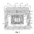
- FIG. 1is a schematic block diagram of a radio frequency detection and identification system in accordance with a preferred embodiment of the invention
- FIG. 2is an electrical schematic circuit diagram of a dual-frequency resonant tag in accordance with a preferred embodiment
- FIG. 3is a top plan view of a dual-frequency resonant tag having an electrical circuit equivalent to the electrical schematic circuit diagram of FIG. 2 ;
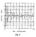
- FIG. 4is a plot of the time domain response of a prototype of the circuit of FIG. 2 ;
- FIG. 5is a plot of the frequency domain response of the prototype of the circuit of FIG. 2 ;
- FIG. 6is a diagram illustrating the interrogation and response characteristics of the radio frequency system of FIG. 1 ;
- FIG. 7is a flow diagram of the operation of the radio frequency system for detecting the presence of an article.
- FIG. 8is a flow diagram of the operation of the radio frequency system for determining the presence of information stored in a plurality of resonant circuits.
- FIG. 1a schematic block diagram of a preferred embodiment of an RF system 10 for detecting an article and/or for identifying information about the article upon which a tag having specific electromagnetic characteristics has been attached.
- the RF system 10is of a type called a pulse-listen system, in which pulses of radio frequency (RF) electromagnetic energy having a predetermined pulse width, pulse rate and carrier frequency are radiated into a detection and identification zone. Following the radiation of each pulse into the detection and identification zone, the RF system 10 probes the electromagnetic field within the zone to determine if a tag having the specific electromagnetic characteristics is present in the detection and identification zone.
- RFradio frequency
- the RF system 10includes a transmitter 12 for radiating a first electromagnetic signal at one or more predetermined primary frequencies.
- the transmitter 12includes a push-pull class D RF amplifier of a conventional design generating a pulse amplitude modulated signal having a pulse duration of approximately five (5) microseconds and having a carrier frequency in the range of 13.5 MHz.
- the carrier frequency of the output signal of the transmitter 12is not limited to 13.5 MHz.
- a transmitter operable at carrier frequencies as low as 1.5 MHz and as high as 7000 MHz.would be within the spirit and scope of the invention.
- the pulse width of the pulse amplitude modulated signalis not limited to five (5) microseconds. As would be appreciated by those skilled in the art, the pulse width of the transmitter 12 would be selected to match the characteristics of the specific tag used in the RF system 10 , such design choice being within the spirit and scope of the invention.
- the preferred embodimentalso includes a frequency synthesizer 52 .
- the frequency synthesizeris a digital frequency synthesizer similar to the digital frequency synthesizer described in allowed U.S. patent application Ser. No. 09/315,452 entitled “Resonant Circuit Detection and Measurement System Employing a Numerically Controlled Oscillator”, now U.S. Pat. No. 6,232,878 which is hereby incorporated by reference in its entirety.
- the frequency synthesizer 52provides a first output signal for driving the transmitter 12 at the primary frequency.
- the frequency synthesizer 52also provides a second output signal for driving a conventional mixer 40 portion of a superhetrodyne receiver 14 .
- the frequency of the second output signal of the frequency synthesizer 52may be the same as the primary frequency or may be different from the primary frequency (i.e. a secondary frequency) depending on the selected mode of operation of the RF system 10 , as discussed below.
- the RF system 10also includes a dual-resonant tag 20 for receiving a first electromagnetic signal from the transmitter 12 and for generating a second electromagnetic signal in response to receiving the first electromagnetic signal.
- the second electromagnetic signalcomprises a frequency component which corresponds to the primary frequency of the first electromagnetic signal and also a secondary frequency component which corresponds to a predetermined secondary frequency which is different from the primary frequency.
- the dual frequency tag 20includes four components namely, a first inductive element or inductance Lp, a second inductive element or inductance Ls, a first capacitive element or capacitance Cp and a second capacitive element or capacitance Cs.
- the aforementioned inductors and capacitorsform a first resonant circuit which is resonant at the primary frequency and a second resonant circuit which is resonant at the second frequency.
- the first and the second resonant circuitsare electromagnetically coupled.
- Additional inductive and/or capacitive elements or componentsmay be added if desired as shown by the dashed lines in FIG. 2 , and the components Lk, Ln and Ck, Cn to form additional resonant circuits which are electromagnetically coupled to the first magnetic circuit.
- the second inductance Lsis connected in series with the second capacitance Cs.
- the first capacitance Cpis connected in parallel with the first inductance Lp.
- the series network (Ls and Cs)is then connected across the parallel network (Lp and Cp).
- the inductors Lp and Lsare magnetically coupled to each other with a coupling coefficient K.
- the coupling of the first and second resonant circuitsmay also be accomplished by capacitive or resistive coupling.
- the values of the inductances Lp, Ls, the capacitances Cp, Cs and the coupling coefficient Kare selected so that the dual frequency tag 20 as configured in FIG. 2 is simultaneously resonant at the first and second resonant frequencies.
- the resonant frequency of the first resonant circuitlays in an Industrial, Scientific and Medical (ISM) frequency band as assigned by the International Telecommunications Union (ITU). Current ISM assigned bands include frequency bands at 13, 27, 430–460, 902–916 and 2350–2450 MHz.
- the resonant frequency of the second resonant circuitlays within a frequency band assigned to EAS systems, currently including approximately 1.95, 3.25, 4.75 and 8.2 MHz.
- the resonant frequency of the first resonant circuitis at about 13.56 MHz.
- the resonant frequency of the second resonant circuitis at about 8.2 MHz.
- FIG. 3is a top plan view of the dual frequency tag 20 in accordance with the electrical circuit shown in FIG. 2 .
- the dual frequency tag 20is comprised of a substantial planar dielectric substrate 22 having a first principal surface or side 24 and a second, opposite principal surface or side 26 .
- the substrate 22may be constructed of any solid material or composite structure or other materials as long as the substrate is insulative, relatively thin and can be used as a dielectric.
- the substrate 22is formed of an insulated dielectric material, for example, a polymeric material such as polyethylene.
- the substrate 22is transparent. However, transparency is not a required characteristic of the substrate 22 .
- the circuit components of the tag 20 as previously describedare formed on both principal surfaces or sides 24 , 26 of the substrate 22 by patterning a conductive material. That is, a first conductive pattern 28 (shown in the lighter color of FIG. 3 ) is formed on the first side 24 of the substrate 22 which is arbitrarily illustrated in FIG. 3 as the bottom or backside of the tag 20 . A second conductive pattern 60 (shown in the darker color on FIG. 3 ) is formed on the second side 26 of the substrate 22 .
- the conductive patterns 28 , 60may be formed on the substrate surfaces 24 , 26 , respectively with electrically conductive materials of a known type and in a manner which is well known to those of skill in the electronic article surveillance art.
- the conductive materialis patterned by a subtractive process (i.e., etching) whereby unwanted material is removed by chemical attack after the desired material has been protected, typically with a printed on etch resistant ink.
- the conductive materialis aluminum.
- other conductive materialse.g., gold, nickel, copper, bronzes, brass, high density graphite, silver-filled conductive epoxies or the like
- other methodse.g., gold, nickel, copper, bronzes, brass, high density graphite, silver-filled conductive epoxies or the like
- other methodsmay be employed for forming the conductive patterns 28 , 60 on the substrate 22 .
- the tag 20may be manufactured by a process of the type described in U.S. Pat. No. 3,913,219, entitled “Planar Circuit Fabrication Process” which is incorporated herein by reference. However, other manufacturing processes can be used if desired.
- both of the inductances or inductive elements Lp and Lsare provided in the form of conductive coils 62 , 64 respectively, both of which are a part of the first conductive pattern 28 . Accordingly, both of the inductances Lp and Ls are located on the first side 24 of the substrate 22 .
- the two conductive coils 62 , 64are wound in the same direction, as shown, to provide a specified amount of inductive coupling between them.
- first plates 66 , 68 of each of the capacitive elements or capacitances Cp and Csare formed as part of the first conductive pattern 28 on the first side 24 of the substrate 22 .
- second plates 70 , 72 of each of the capacitances Cp and Csare formed as part of the second conductive pattern 60 and are located on the second side 26 of the substrate 22 .
- a direct electrical connectionextends through the substrate 22 to electrically connect the first conductive pattern 28 to the second conductive pattern 60 to thereby continuously maintain both sides of the substrate 22 at substantially the same static charge level. Referring to FIG.
- the first conductive pattern 28includes a generally square land 74 on the inner most end of the coil portion 62 , which forms the first inductance Lp.
- a generally square land 78is formed as part of the second conductive pattern 60 and is connected by a conductive beam 80 to the portion of the second conductive pattern 60 , which forms the second plate 70 of the first capacitance Cp.
- the conductive lands 74 , 78are aligned with each other.
- the direct electrical connectionis made by a weld through connection (not shown), which extends between conductive land 74 of the first conductive pattern 28 and conductive land 78 of the second conductive pattern 60 .
- the direct electrical connection between the lands 74 , 78is formed by a weld in a manner which is well known to those of ordinary skill in the EAS art.
- FIG. 4there is shown a plot of the transient response of a prototype of the preferred embodiment of the dual frequency tag 20 after being radiated with a pulsed electromagnetic field having a five (5) microsecond pulse width and a carrier frequency of 13.56 MHz.
- the prototypewas designed to simultaneously resonate at both 13.56 MHz. and at 8.2 MHz.
- the prototype tagwas placed at the center of a rectangular loop antenna fabricated from one (1) inch copper tape and was radiated by applying a radio frequency (RF) signal to the antenna.
- RFradio frequency
- a probe connected to an oscilloscopewas used to measure the residual (ring-down) electromagnetic field in the vicinity of the prototype tag when the transmitted signal was switched off.
- FIG. 4clearly shows the presence of at least two frequency components in the time-domain ring-down signal.
- the time domain signal shown in FIG. 4was subsequently transformed into the frequency domain by operating on the signal data with a fast Fourier transform (FFT).
- FFTfast Fourier transform
- FIG. 5The result of applying the FFT to the data of FIG. 4 is shown in FIG. 5 , in which obvious peaks in the frequency spectrum are shown at about 13.56 MHz. and at about 8.2 MHz.
- the preferred embodiment of the RF system 10also includes a superhetrodyne receiver 14 of conventional design for receiving the second electromagnetic signal from an antenna 30 via an antenna switch 50 and a bandpass filter 32 , and for converting the received RF signal to a baseband signal.
- the receivercomprises an RF amplifier 36 , a band pass filter 38 , the mixer 40 , a low pass filter 42 and an analog-to-digital converter 44 .
- the RF amplifier 36 and the band pass filter 38have a bandwidth for covering the range of the signals desired to be detected.
- RF amplifier 36 and the bandpass filterhave a bandwidth extending from about 5.0 MHz. to about 15.0. MHz.
- the bandpass characteristic of the RF amplifier 36 and the bandpass filter 38could be a single substantially flat bandpass characteristic, a characteristic of multiple pass bands, or could be tunable to a plurality of narrower bandwidths depending on the design needs.
- the output of the bandpass filter 38is connected to the mixer 40 .
- the mixer 40receives the output signal from the bandpass filter 38 and the second output signal from the frequency synthesizer 52 and converts the frequency of the output signal of the bandpass filter 38 to a baseband signal by multiplying together the output signal of the bandpass filter 38 and the second output signal of frequency synthesizer 52 .
- the output of the mixer 40is filtered by the low pass filter 42 prior to applying the baseband signal to the analog-to-digital converter 44 .
- the analog-to-digital converter 44converts the analog baseband signal to a digital signal compatible with an input to a computer 46 .
- the receiver 14is not limited to accepting an input signal extending from about 5.0 MHz. to about 15.0. MHz. As contemplated, a receiver capable of receiving frequencies as low as 1.5 MHz and as high as 7000 MHz. is within the spirit and scope of the invention.
- the RF systemfurther includes an antenna 30 for radiating the first electromagnetic signal and for providing the second electromagnetic signal received from the tag 20 to the receiver 14 .
- the antennais a loop antenna which provides a detection and identification zone in the near field proximate to the antenna 30 and generally provides for cancellation of the electromagnetic field in the far field.
- a suitable antennais that disclosed in U.S. Pat. No. 5,602,556 entitled “Transmit and Receive Loop Antenna” which is hereby incorporated by reference in its entirety.
- other types of antennascould be used.
- the antenna 30is connected to the transmitter 12 by the antenna switch 50 when the transmitter 12 is transmitting the first electromagnetic signal, i.e. during the “pulse period” and is connected to the receiver 14 when it is desired to receive the second electromagnetic signal, i.e. during the “listen” period.
- the preferred embodiment of the RF system 10further includes a computer 46 connected to an output of the receiver 14 .
- the computer 46processes the received second electromagnetic signal and generates an output signal when a signature of the received second electromagnetic signal meets a predetermined criterion.
- the criteria for generating the output signalmay include the detection of the secondary frequency alone or may include the detection of both the primary frequency and the secondary frequency. Such processing for detecting the presence of resonant tags is well known to those skilled in the art and is not further disclosed here, for the sake of brevity.
- the computer 46also provides the overall timing and control for the RF system 10 .
- the computer 46comprises a commercially available digital signal processor computer chip selected from a family such as the TMS320C54X, available from Texas Instruments Corporation, volatile random access memory (RAM) and non-volatile read only memory (ROM).
- Computer executable software code stored in the ROM and executing in the computer chip and in the RAMcontrols the RF system 10 by providing control signals over control wires 34 to control the frequency of the frequency synthesizer 52 , the pulse width of the output signal of the transmitter 12 and the position of the antenna switch 50 .
- FIGS. 6 and 7there are shown a timing diagram and an accompanying flow chart of a process 100 illustrating the operation of the RF system 10 for detecting a resonant tag 20 having two electromagnetically coupled resonant circuits, in accordance with the preferred embodiment.
- the computer 46controls the frequency synthesizer 52 to generate a signal at the primary frequency, controls the antenna switch 50 to connect the transmitter 12 to the antenna 30 and gates the transmitter 12 on to generate a pulse of RF energy to form the first electromagnetic signal at the predetermined primary frequency.
- the computer 46controls the antenna switch 50 to connect the antenna 30 to the receiver 14 , thereby preparing the receiver 14 to receive the second electromagnetic signal at the primary frequency.
- the second electromagnetic signal received by the receiver 14 at the primary frequencyis processed by the computer 46 (step 106 ) to determine if the signal meets a predetermined criteria which characterizes the resonant tag 20 ring-down signal at the primary frequency, such criteria being stored in the computer 46 . If the stored criteria for the ring-down signal is met by the received signal, the computer 46 retransmits the first electromagnetic signal at the primary frequency at times t 4 to t 5 (step 108 ). If the ring-down signal does not meet the predetermined criteria, step 102 is repeated.
- the computer 46controls the frequency synthesizer 52 to generate a signal at the predetermined secondary frequency and controls the antenna switch 50 to connect the receiver 14 to the antenna 30 to prepare the receiver for receiving the second electromagnetic signal at the secondary frequency.
- the second electromagnetic signal received by the receiver 14 at the secondary frequencyis processed by the computer 46 (step 112 ) to determine if the signal meets a predetermined criteria, also stored in the computer 46 , which characterizes the resonant tag 20 ring-down signal at the secondary frequency. If the stored criteria for the ring-down signal at the secondary frequency is met by the received signal, the computer 46 generates an alarm indicating the presence of a resonant tag 20 within the detection zone (step 114 ). If the ring-down signal does not meet the predetermined criteria, the process of detecting the resonant tag 20 returns to step 102 .
- detecting the ring-down signals from the resonant tag 20 at both the primary frequency and the secondary frequencysubstantially reduces the false alarm rate for an EAS system operating in an interference environment.
- the primary and the secondary frequenciescould be also be detected simultaneously based on a single transmission of the primary frequency.
- detection of the resonant tag 20 by detecting only the primary frequency or only the secondary frequency aloneis, possible and is within the spirit and scope of the invention.
- the resonant frequencies of the resonant circuits which comprise the resonant tag 20have manufacturing tolerances which may result in the frequencies of the ring-down frequencies deviating from the predetermined primary and secondary frequencies sufficiently to degrade detection of the resonant tag 20 .
- the first resonant circuit of the resonant tag 20is trimmed by a laser or other means so that the resonant frequency of the first resonant circuit is acceptably close to the predetermined primary frequency.
- the bandwidth of the receivermay be made narrow for detecting the primary frequency and wide for detecting the secondary frequency to allow for the tolerances of the second resonant circuit at the secondary frequency.
- the second resonant circuitmay also be trimmed to be close to the predetermined secondary frequency.
- a.Scan the frequency of the first electromagnetic signal over the uncertainty range of the first resonant circuit, as is commonly done for pulse-listen type of EAS systems; when a detection at the primary frequency is indicated, re-transmit the first electromagnetic signal at the indicated primary frequency and detect the second electromagnetic signal at the secondary frequency by: (1) employing an RF bandwidth in the receiver 14 which covers the uncertainty range of the second resonant circuit, (2) using a parallel bank of filters, such as provided by an FFT to cover the uncertainty range of the second resonant circuit, or (3) continually retransmitting the primary frequency and scanning the uncertainty range of the second resonant circuit.
- b.Scan the frequency of the first electromagnetic signal over the uncertainty range of the first resonant circuit; for each transmission of the primary frequency: detect the second electromagnetic signal at the secondary frequency by: (1) employing an RF bandwidth in the receiver 14 which covers the uncertainty range of the second resonant circuit, (2) using a parallel bank of filters, such as provided by an FFT to cover the uncertainty range of the second resonant circuit, or (3) continually retransmitting the primary frequency and scanning the uncertainty range of the second resonant circuit.
- the present inventionis not limited to merely detecting the presence of a resonant tag 20 in a detection zone by detecting the ring-down of one or two resonant circuits as for an EAS surveillance function.
- the present inventionalso includes within its scope a radio frequency identification (RFID) capability which employs a single tag having two or more resonant circuits, (see FIG. 2 ), with each resonant circuit being designed to resonate at a different frequency.
- RFIDradio frequency identification
- Such a tagwould have a single first resonant circuit resonant at a primary frequency and a plurality of second resonant circuits, each of which second resonant circuits resonating at a different frequency and each of such second resonant circuits being electromagnetically coupled to the first resonant circuit.
- the resonant tag 20could include a first resonant circuit at the primary frequency and four different second resonant circuits, each resonating at a different resonant frequency within the detection range of associated equipment.
- the preferred detection frequency rangeextends from about 10 MHz to about 30 MHz.
- any other frequency rangecould be used.
- the detection frequency range of 10–30 MHzit is possible to have up to 50 resonant circuits, each of which resonates at a different frequency without overlapping or interfering with one another.
- the first resonant circuitcould resonate at a first selected frequency within the detection frequency range, for example, 14.4 MHz leaving 49 available frequencies within the detection frequency range for the other three resonant circuits of the tag.
- the second resonant frequencycould then be selected to resonate at a second frequency within the detection frequency range, for example, 15.6 MHz leaving 48 possible frequencies for the other two resonant circuits of the tag.
- the third resonant frequencycould be selected and the tag fabricated to resonate at a third frequency, for example, 20 MHz leaving 47 possible frequencies for the fourth resonant frequency.
- the fourth resonant frequencycould then be selected and the tag fabricated to resonate at a fourth frequency, for example, 19.2 MHz.
- a tag having four specifically identified resonant frequencies and a unique signature when interrogatedcould then be assigned a particular identification number. Because of the number of potential frequencies within the detection frequency range, a tag having four resonant circuits thereon, each with a different frequency, is capable of having approximately, 5.2 million combinations or approximately 22 bits of data.
- FIG. 8is a flow diagram of a preferred process 200 for using the RF system 10 , as shown in FIG. 1 , for identifying the resonant frequencies of the RFID tag by interrogating the tag at the primary frequency of the RFID tag and by detecting the presence or absence of a predetermined ring-down signature at each of N secondary resonant frequencies.
- the computer 46controls the frequency synthesizer 52 to generate a signal at the primary frequency, controls the antenna switch 50 to connect the transmitter 12 to the antenna 30 and gates the transmitter 12 on to generate a pulse of RF energy to form the first electromagnetic signal at the predetermined primary frequency.
- the computer 46controls the antenna switch 50 to connect the antenna 30 to the receiver 14 , thereby preparing the receiver 14 to receive the second electromagnetic signal at the primary frequency.
- the second electromagnetic signal received by the receiver 14 at the primary frequencyis processed by the computer 46 (step 206 ) to determine if the signal meets a predetermined criteria which characterizes the resonant tag 20 ring-down signal at the primary frequency, such criteria being stored in the computer 46 . If the stored criteria for the ring-down signal is met by the received signal, the computer 46 sets a counter to the integer number “one” (step 208 ) and retransmits the first electromagnetic signal at the primary frequency (step 210 ).
- the computer 46controls the frequency synthesizer 52 to generate a signal at the Kth predetermined secondary frequency and controls the antenna switch 50 to connect the receiver 14 to the antenna 30 to prepare the receiver for receiving the second electromagnetic signal at the Kth secondary frequency.
- the second electromagnetic signal received by the receiver 14 at the secondary frequencyis processed to determine if the signal meets the predetermined ring-down signature criteria and a result of the processing is stored by the computer 46 (step 214 ).
- the current value of the counteris compared with the number “N” which represents the number of secondary frequencies to be received. If the value K of the counter is less than N, the process 200 is continued at step 210 . If the value K of the counter is equal to N the process 200 is completed by reporting which secondary frequencies were received having the predetermined ring-down signature (step 218 ), and the RFID process 200 is started again at step 202 .
- the present inventionprovides a system and a method for interrogating a resonant tag at a single (primary) frequency and for receiving information stored in the tag by one or more resonant circuits which are resonant at frequencies other than the primary frequency. Accordingly, the present invention provides a means for reducing the false alarm rate of an EAS system and a means for interrogating an RFID tag to receive information stored in the tag by radiating electromagnetic energy at only the single (primary) frequency.
Landscapes
- Physics & Mathematics (AREA)
- Engineering & Computer Science (AREA)
- Automation & Control Theory (AREA)
- Computer Security & Cryptography (AREA)
- Electromagnetism (AREA)
- General Physics & Mathematics (AREA)
- Burglar Alarm Systems (AREA)
- Radar Systems Or Details Thereof (AREA)
- Near-Field Transmission Systems (AREA)
- Geophysics And Detection Of Objects (AREA)
Abstract
Description
Claims (25)
Priority Applications (1)
| Application Number | Priority Date | Filing Date | Title |
|---|---|---|---|
| US11/123,736US7187289B2 (en) | 2000-05-08 | 2005-05-06 | Radio frequency detection and identification system |
Applications Claiming Priority (3)
| Application Number | Priority Date | Filing Date | Title |
|---|---|---|---|
| US20239100P | 2000-05-08 | 2000-05-08 | |
| US09/848,827US6894614B2 (en) | 2000-05-08 | 2001-05-04 | Radio frequency detection and identification system |
| US11/123,736US7187289B2 (en) | 2000-05-08 | 2005-05-06 | Radio frequency detection and identification system |
Related Parent Applications (1)
| Application Number | Title | Priority Date | Filing Date |
|---|---|---|---|
| US09/848,827ContinuationUS6894614B2 (en) | 2000-05-08 | 2001-05-04 | Radio frequency detection and identification system |
Publications (2)
| Publication Number | Publication Date |
|---|---|
| US20050200483A1 US20050200483A1 (en) | 2005-09-15 |
| US7187289B2true US7187289B2 (en) | 2007-03-06 |
Family
ID=22749680
Family Applications (2)
| Application Number | Title | Priority Date | Filing Date |
|---|---|---|---|
| US09/848,827Expired - Fee RelatedUS6894614B2 (en) | 2000-05-08 | 2001-05-04 | Radio frequency detection and identification system |
| US11/123,736Expired - Fee RelatedUS7187289B2 (en) | 2000-05-08 | 2005-05-06 | Radio frequency detection and identification system |
Family Applications Before (1)
| Application Number | Title | Priority Date | Filing Date |
|---|---|---|---|
| US09/848,827Expired - Fee RelatedUS6894614B2 (en) | 2000-05-08 | 2001-05-04 | Radio frequency detection and identification system |
Country Status (16)
| Country | Link |
|---|---|
| US (2) | US6894614B2 (en) |
| EP (1) | EP1285417B1 (en) |
| JP (1) | JP4663200B2 (en) |
| KR (1) | KR20030007587A (en) |
| CN (1) | CN1236408C (en) |
| AR (1) | AR028427A1 (en) |
| AT (1) | ATE487998T1 (en) |
| AU (2) | AU6119201A (en) |
| BR (1) | BR0110648A (en) |
| CA (1) | CA2408488C (en) |
| DE (1) | DE60143429D1 (en) |
| ES (1) | ES2355706T3 (en) |
| IL (1) | IL152588A0 (en) |
| MX (1) | MXPA02010979A (en) |
| TW (1) | TW561430B (en) |
| WO (1) | WO2001086967A2 (en) |
Cited By (11)
| Publication number | Priority date | Publication date | Assignee | Title |
|---|---|---|---|---|
| US20070115130A1 (en)* | 2005-11-14 | 2007-05-24 | Ronald Eveland | Multi-dimensional, broadband track and trace sensor radio frequency identification device |
| US20070229264A1 (en)* | 2005-11-14 | 2007-10-04 | Ronald Eveland | Software method and system for encapsulation of RFID data into a standardized globally routable format |
| US20070262866A1 (en)* | 2005-11-14 | 2007-11-15 | Ronald Eveland | Multi-Dimensional Broadband Track and Trace Sensor Radio Frequency Identification Device |
| US20080076536A1 (en)* | 2006-09-26 | 2008-03-27 | Bally Gaming, Inc. | Resonant gaming chip identification system and method |
| US20080084312A1 (en)* | 2006-10-10 | 2008-04-10 | Daily Michael A | Radio frequency identification layered foam tag |
| US20080211671A1 (en)* | 2007-01-11 | 2008-09-04 | Dagosi, Llc | Smart rfid checkout kiosk |
| US20080249883A1 (en)* | 2005-04-07 | 2008-10-09 | Daily Michael A | Self Checkout Kiosk and Retail Security System |
| US20080266099A1 (en)* | 2007-04-24 | 2008-10-30 | Daily Michael A | Radio frequency identification point of sale unassisted retail transaction and digital media kiosk |
| US20090051491A1 (en)* | 2007-08-20 | 2009-02-26 | Gui-Yang Lu | Radio-frequency identification system |
| US20110205030A1 (en)* | 2010-02-03 | 2011-08-25 | Nxp B.V. | Method of de-activating and activating an electronic article surveillance (esa) device, and an eas device |
| US8272945B2 (en) | 2007-11-02 | 2012-09-25 | Bally Gaming, Inc. | Game related systems, methods, and articles that combine virtual and physical elements |
Families Citing this family (112)
| Publication number | Priority date | Publication date | Assignee | Title |
|---|---|---|---|---|
| SE520154C2 (en)* | 1999-04-19 | 2003-06-03 | Jokab Safety Ab | Proximity switches, targets, systems of such proximity switches and targets and method for determining the presence of a target by means of a proximity switch |
| US7889052B2 (en) | 2001-07-10 | 2011-02-15 | Xatra Fund Mx, Llc | Authorizing payment subsequent to RF transactions |
| IL152588A0 (en)* | 2000-05-08 | 2003-05-29 | Checkpoint Systems Inc | Radio frequency detection and identification system |
| WO2002078513A2 (en) | 2001-03-30 | 2002-10-10 | Augmentech, Inc. | Patient incontinence/position monitoring apparatus and method of use thereof |
| US7725427B2 (en) | 2001-05-25 | 2010-05-25 | Fred Bishop | Recurrent billing maintenance with radio frequency payment devices |
| US8548927B2 (en) | 2001-07-10 | 2013-10-01 | Xatra Fund Mx, Llc | Biometric registration for facilitating an RF transaction |
| US8279042B2 (en) | 2001-07-10 | 2012-10-02 | Xatra Fund Mx, Llc | Iris scan biometrics on a payment device |
| US8294552B2 (en) | 2001-07-10 | 2012-10-23 | Xatra Fund Mx, Llc | Facial scan biometrics on a payment device |
| US9024719B1 (en) | 2001-07-10 | 2015-05-05 | Xatra Fund Mx, Llc | RF transaction system and method for storing user personal data |
| US9031880B2 (en) | 2001-07-10 | 2015-05-12 | Iii Holdings 1, Llc | Systems and methods for non-traditional payment using biometric data |
| US7735725B1 (en) | 2001-07-10 | 2010-06-15 | Fred Bishop | Processing an RF transaction using a routing number |
| US7543738B1 (en) | 2001-07-10 | 2009-06-09 | American Express Travel Related Services Company, Inc. | System and method for secure transactions manageable by a transaction account provider |
| US7668750B2 (en) | 2001-07-10 | 2010-02-23 | David S Bonalle | Securing RF transactions using a transactions counter |
| US7360689B2 (en)* | 2001-07-10 | 2008-04-22 | American Express Travel Related Services Company, Inc. | Method and system for proffering multiple biometrics for use with a FOB |
| US8001054B1 (en) | 2001-07-10 | 2011-08-16 | American Express Travel Related Services Company, Inc. | System and method for generating an unpredictable number using a seeded algorithm |
| US7249112B2 (en) | 2002-07-09 | 2007-07-24 | American Express Travel Related Services Company, Inc. | System and method for assigning a funding source for a radio frequency identification device |
| US9454752B2 (en) | 2001-07-10 | 2016-09-27 | Chartoleaux Kg Limited Liability Company | Reload protocol at a transaction processing entity |
| US7303120B2 (en) | 2001-07-10 | 2007-12-04 | American Express Travel Related Services Company, Inc. | System for biometric security using a FOB |
| US7705732B2 (en) | 2001-07-10 | 2010-04-27 | Fred Bishop | Authenticating an RF transaction using a transaction counter |
| US20040236699A1 (en) | 2001-07-10 | 2004-11-25 | American Express Travel Related Services Company, Inc. | Method and system for hand geometry recognition biometrics on a fob |
| US20030112862A1 (en)* | 2001-12-13 | 2003-06-19 | The National University Of Singapore | Method and apparatus to generate ON-OFF keying signals suitable for communications |
| DE10214188B4 (en)* | 2002-03-28 | 2005-08-25 | Siemens Ag | Method for secure transmission of data, in particular for transmission over an air interface |
| PT102793A (en)* | 2002-06-18 | 2003-12-31 | Gantle Trading & Services Ld | DEVICE FOR INDIVIDUALIZED IDENTIFICATION OF REMOTE ITEMS |
| US6805287B2 (en) | 2002-09-12 | 2004-10-19 | American Express Travel Related Services Company, Inc. | System and method for converting a stored value card to a credit card |
| US9248003B2 (en)* | 2002-12-30 | 2016-02-02 | Varian Medical Systems, Inc. | Receiver used in marker localization sensing system and tunable to marker frequency |
| CA2455719A1 (en)* | 2003-01-24 | 2004-07-24 | Christopher K. Mitchell | Apparatus and methods for protecting valuables |
| US7283053B2 (en)* | 2003-01-27 | 2007-10-16 | University Of Pittsburgh - Of The Commonwealth System Of Higher Education | RFID radio frequency identification or property monitoring method and associated apparatus |
| WO2004094012A2 (en) | 2003-04-17 | 2004-11-04 | Alliance Gaming Corporation | Wireless monitoring of playing cards and/or wagers in gaming |
| US7183917B2 (en)* | 2003-05-19 | 2007-02-27 | Checkpoint Systems, Inc. | EAS/RFID identification hard tags |
| CN1833279B (en)* | 2003-05-30 | 2010-11-03 | 松下电器产业株式会社 | Optical disc |
| US7023342B2 (en)* | 2003-09-17 | 2006-04-04 | The United States Of America As Represented By The Secretary Of The Navy | Continuous wave (CW)—fixed multiple frequency triggered, radio frequency identification (RFID) tag and system and method employing same |
| DE20314836U1 (en) | 2003-09-23 | 2003-11-20 | Feig electronic GmbH, 35781 Weilburg | Reader antenna for Radio Frequency Identification system consists of two conductors connected to oscillation circuit with inductance, capacitance and resistor |
| US7199717B2 (en)* | 2004-02-17 | 2007-04-03 | Sensormatic Electronics Corporation | Frequency-division marker for an electronic article surveillance system |
| US7164358B2 (en)* | 2004-02-17 | 2007-01-16 | Sensormatic Electronics Corporation | Frequency divider with variable capacitance |
| NL1025725C2 (en)* | 2004-03-15 | 2005-09-16 | Nedap Nv | Combined RFID and anti theft label for e.g. shop goods, contains main outer coil and auxiliary inner coil |
| US7152804B1 (en) | 2004-03-15 | 2006-12-26 | Kovlo, Inc. | MOS electronic article surveillance, RF and/or RF identification tag/device, and methods for making and using the same |
| WO2005088850A1 (en)* | 2004-03-17 | 2005-09-22 | Brother Kogyo Kabushiki Kaisha | Position detection system, response device and query device, radio communication system, position detection method, position detection program, and information recording medium |
| EP1760900B1 (en)* | 2004-06-10 | 2011-04-06 | Panasonic Corporation | Rfid tag and rfid tag communication distance modification method |
| US7363504B2 (en) | 2004-07-01 | 2008-04-22 | American Express Travel Related Services Company, Inc. | Method and system for keystroke scan recognition biometrics on a smartcard |
| US7318550B2 (en) | 2004-07-01 | 2008-01-15 | American Express Travel Related Services Company, Inc. | Biometric safeguard method for use with a smartcard |
| US7341181B2 (en) | 2004-07-01 | 2008-03-11 | American Express Travel Related Services Company, Inc. | Method for biometric security using a smartcard |
| US7325724B2 (en) | 2004-07-01 | 2008-02-05 | American Express Travel Related Services Company, Inc. | Method for registering a biometric for use with a smartcard |
| US7314164B2 (en) | 2004-07-01 | 2008-01-01 | American Express Travel Related Services Company, Inc. | System for biometric security using a smartcard |
| US7314165B2 (en)* | 2004-07-01 | 2008-01-01 | American Express Travel Related Services Company, Inc. | Method and system for smellprint recognition biometrics on a smartcard |
| US8570156B2 (en)* | 2010-09-01 | 2013-10-29 | Quake Global, Inc. | Pluggable small form-factor UHF RFID reader |
| US7286053B1 (en) | 2004-07-31 | 2007-10-23 | Kovio, Inc. | Electronic article surveillance (EAS) tag/device with coplanar and/or multiple coil circuits, an EAS tag/device with two or more memory bits, and methods for tuning the resonant frequency of an RLC EAS tag/device |
| US9953259B2 (en) | 2004-10-08 | 2018-04-24 | Thin Film Electronics, Asa | RF and/or RF identification tag/device having an integrated interposer, and methods for making and using the same |
| US20060085390A1 (en)* | 2004-10-15 | 2006-04-20 | Ming-Feng Ho | Method and system for online real-time query about current status of optical component |
| US7148804B2 (en)* | 2004-11-08 | 2006-12-12 | Checkpoint Systems, Inc. | System and method for detecting EAS/RFID tags using step listen |
| RU2400818C2 (en)* | 2004-11-18 | 2010-09-27 | Сенсормэтик Электроникс, Ллк | Eas reader detecting eas function in rfid device |
| US7642915B2 (en)* | 2005-01-18 | 2010-01-05 | Checkpoint Systems, Inc. | Multiple frequency detection system |
| NL1028063C2 (en)* | 2005-01-18 | 2006-07-19 | Nedap Nv | Combined security tag and identification label for shop goods, comprises price label part with large resonance loop connected to security tag part with small resonance loop |
| KR101075651B1 (en)* | 2005-02-07 | 2011-10-21 | 삼성전자주식회사 | Privacy protection rfid tag and method for protecting privacy information |
| CA2601572A1 (en)* | 2005-03-18 | 2006-09-28 | Gatekeeper Systems, Inc. | Power generation systems and methods for wheeled objects |
| TW200641695A (en)* | 2005-05-18 | 2006-12-01 | Elitegroup Computer Sys Co Ltd | Method and related apparatus for enhancing information security of a computer system |
| US8131213B2 (en)* | 2005-06-15 | 2012-03-06 | Wfs Technologies Ltd. | Sea vessel tagging apparatus and system |
| US7782189B2 (en)* | 2005-06-20 | 2010-08-24 | Carestream Health, Inc. | System to monitor the ingestion of medicines |
| US7616111B2 (en) | 2005-06-20 | 2009-11-10 | Carestream Health, Inc. | System to monitor the ingestion of medicines |
| US7687327B2 (en)* | 2005-07-08 | 2010-03-30 | Kovio, Inc, | Methods for manufacturing RFID tags and structures formed therefrom |
| US20070045018A1 (en)* | 2005-08-25 | 2007-03-01 | Carter Scott J | Systems and methods for controlling powered vehicles near a restricted region |
| JP4817768B2 (en)* | 2005-09-07 | 2011-11-16 | 富士通株式会社 | Information access system and active contactless information storage device |
| JP2007086863A (en) | 2005-09-20 | 2007-04-05 | Fuji Xerox Co Ltd | Non-contact ic tag, package of member equipped with non-contact ic tag and device using member equipped with non-contact ic tag |
| WO2007130147A2 (en)* | 2005-11-04 | 2007-11-15 | Gerald Giasson | Security sensor system |
| DE602007012999D1 (en)* | 2006-01-07 | 2011-04-21 | Arthur Koblasz | USE OF RFID TO PREVENT OR DETECT SCORES, BREAKS, BEDDING, AND MEDICAL FAULTS |
| KR100666338B1 (en)* | 2006-01-17 | 2007-01-09 | 인티그런트 테크놀로지즈(주) | Radio Reader and Radio Identification System. |
| US7519328B2 (en)* | 2006-01-19 | 2009-04-14 | Murata Manufacturing Co., Ltd. | Wireless IC device and component for wireless IC device |
| KR101050330B1 (en)* | 2006-01-19 | 2011-07-19 | 가부시키가이샤 무라타 세이사쿠쇼 | Radio ic device and radio ic device part |
| US7679510B2 (en)* | 2006-02-06 | 2010-03-16 | Hershey Chocolate And Confectionary Corporation | RFID product identification and tracking system |
| US7989986B2 (en)* | 2006-03-23 | 2011-08-02 | Access Business Group International Llc | Inductive power supply with device identification |
| US11245287B2 (en) | 2006-03-23 | 2022-02-08 | Philips Ip Ventures B.V. | Inductive power supply with device identification |
| US7355150B2 (en) | 2006-03-23 | 2008-04-08 | Access Business Group International Llc | Food preparation system with inductive power |
| US7753779B2 (en) | 2006-06-16 | 2010-07-13 | Bally Gaming, Inc. | Gaming chip communication system and method |
| JP4584197B2 (en)* | 2006-06-30 | 2010-11-17 | 富士通株式会社 | Information access system, active contactless information storage device, and method of accessing information in contactless information storage device |
| US8115650B2 (en)* | 2006-07-11 | 2012-02-14 | PSST Mobile Equipment Ltd. - Richard Shervey | Radio frequency identification based personnel safety system |
| US8207826B2 (en)* | 2006-10-03 | 2012-06-26 | Ncr Corporation | Methods and apparatus for analyzing signal conditions affecting operation of an RFID communication device |
| US20090058614A1 (en)* | 2007-08-30 | 2009-03-05 | Em Microelectronic-Marin S.A. | Electronic identification device or transponder fitted with two antennae tuned to different frequencies |
| JP5536651B2 (en)* | 2007-09-24 | 2014-07-02 | クーパー タイヤ アンド ラバー カンパニー | Automatic antenna tuner system for RFID |
| US8633821B2 (en)* | 2007-12-03 | 2014-01-21 | Avery Dennison Corporation | Dual use RFID/EAS device |
| WO2009112999A1 (en)* | 2008-03-14 | 2009-09-17 | Koninklijke Philips Electronics N.V. | Rf identification tag |
| TW201001958A (en) | 2008-04-29 | 2010-01-01 | Odin Technologies Inc | Method and apparatus for a deployable radio-frequency identification portal system |
| EP2141635A1 (en)* | 2008-06-30 | 2010-01-06 | Nederlandse Organisatie voor toegepast- natuurwetenschappelijk onderzoek TNO | A radio frequency tag |
| US7973660B2 (en)* | 2008-07-23 | 2011-07-05 | Sensormatic Electronics, LLC | Electronic article surveillance deactivator with multiple label detection and method thereof |
| WO2010068511A1 (en)* | 2008-11-25 | 2010-06-17 | Kovio, Inc. | Tunable capacitors |
| CN102224768A (en)* | 2008-11-25 | 2011-10-19 | Kovio股份有限公司 | Printed antennas, methods of printing an antenna, and devices including the printed antenna |
| WO2010062921A1 (en)* | 2008-11-26 | 2010-06-03 | Kovio, Inc. | Random delay generation for thin-film transistor based circuits |
| US20100148965A1 (en)* | 2008-12-16 | 2010-06-17 | Sensormatic Electronics Corporation | Method and system for item level uhf rfid tag with low frequency power assist |
| US9342716B2 (en) | 2010-02-04 | 2016-05-17 | Carefusion 303, Inc. | Software-defined multi-mode RFID read devices |
| WO2014134157A1 (en) | 2013-02-26 | 2014-09-04 | Quake Global, Inc. | Methods and apparatus for automatic identification wristband |
| CA2720194A1 (en)* | 2010-11-05 | 2012-05-05 | Prairie Tech Enterprises Ltd. | Radio-frequency identification safety device |
| US20120223811A1 (en) | 2011-03-03 | 2012-09-06 | Checkpoint Systems, Inc. | Multiple Antenna Localizing |
| JP5688044B2 (en)* | 2012-04-05 | 2015-03-25 | 富士通フロンテック株式会社 | Reader / writer device and carrier sense control method |
| US9841492B2 (en) | 2013-02-25 | 2017-12-12 | Quake Global, Inc. | Ceiling-mounted RFID-enabled tracking |
| DK2961924T3 (en) | 2013-02-28 | 2020-11-16 | Weatherford Tech Holdings Llc | BOREHOLE COMMUNICATION |
| RU2766836C2 (en)* | 2013-02-28 | 2022-03-16 | ВЕЗЕРФОРД ТЕКНОЛОДЖИ ХОЛДИНГЗ, ЭлЭлСи | Borehole communication |
| GB201303614D0 (en) | 2013-02-28 | 2013-04-17 | Petrowell Ltd | Downhole detection |
| US9395434B2 (en) | 2013-04-25 | 2016-07-19 | The United States Of America As Represented By The Secretary Of The Army | Multitone harmonic radar and method of use |
| US10203405B2 (en) | 2013-04-25 | 2019-02-12 | The United States Of America As Represented By The Secretary Of The Army | Multitone radar with range determination and method of use |
| US9466018B2 (en)* | 2014-05-23 | 2016-10-11 | Apple Inc. | Displays with radio-frequency identifiers |
| CA2955623C (en) | 2014-07-25 | 2024-05-28 | Gatekeeper Systems, Inc. | Monitoring usage or status of cart retrievers |
| EP3185431B1 (en)* | 2015-12-22 | 2021-09-22 | Intel Corporation | Polling for near field communication |
| US10481256B2 (en)* | 2016-04-06 | 2019-11-19 | Walmart Apollo, Llc | Shopping cart corral system and associated systems and methods |
| US10234543B2 (en) | 2016-04-20 | 2019-03-19 | The United States Of America As Represented By The Secretary Of The Army | Methods and systems for locating targets using non linear radar with a matched filter which uses exponential value of the transmit signal |
| US20180040218A1 (en)* | 2016-08-04 | 2018-02-08 | Tyco Fire & Security Gmbh | Pulsed electronic article surveillance detection system absent of a phasing requirement |
| CN106556875A (en)* | 2016-11-21 | 2017-04-05 | 浪潮(苏州)金融技术服务有限公司 | A kind of method of detection means and its detection time writer |
| CN106652294B (en)* | 2016-12-22 | 2019-04-30 | 思创医惠科技股份有限公司 | Burglary-resisting system decoder detection device |
| RU2639076C1 (en)* | 2017-01-23 | 2017-12-19 | Павел Владимирович Васин | Security system |
| CN109842425B (en)* | 2017-11-28 | 2021-03-19 | 瑞昱半导体股份有限公司 | Transceiver circuit and wiring configuration method thereof |
| EP3794566A1 (en) | 2018-05-17 | 2021-03-24 | Checkpoint Systems, Inc. | Dual hard tag |
| EP3935409A1 (en) | 2019-03-05 | 2022-01-12 | The Procter & Gamble Company | Wireless measurement of human product interaction |
| RU2703353C1 (en)* | 2019-03-19 | 2019-10-16 | Акционерное общество "Федеральный научно-производственный центр "Производственное объединение "Старт" им. М.В. Проценко" (АО "ФНПЦ ПО "Старт" им. М.В. Проценко") | Mobile system for guarding an extended linear object from unauthorized actions on local areas of terrain in the presence of nearby overhead power lines |
| US11907790B2 (en)* | 2020-03-06 | 2024-02-20 | Hutchinson Technology Incorporated | Component identification |
| JP2023053813A (en)* | 2021-10-01 | 2023-04-13 | タカヤ株式会社 | Presence detection system |
Citations (22)
| Publication number | Priority date | Publication date | Assignee | Title |
|---|---|---|---|---|
| US3913219A (en) | 1974-05-24 | 1975-10-21 | Lichtblau G J | Planar circuit fabrication process |
| US4023167A (en) | 1975-06-16 | 1977-05-10 | Wahlstrom Sven E | Radio frequency detection system and method for passive resonance circuits |
| US4429302A (en)* | 1981-10-08 | 1984-01-31 | I. D. Engineering, Inc. | Electronic security system with noise rejection |
| US4481428A (en) | 1981-05-19 | 1984-11-06 | Security Tag Systems, Inc. | Batteryless, portable, frequency divider useful as a transponder of electromagnetic radiation |
| US4670740A (en) | 1985-11-04 | 1987-06-02 | Security Tag Systems, Inc. | Portable, batteryless, frequency divider consisting of inductor and diode |
| US4700179A (en) | 1982-04-12 | 1987-10-13 | Ici Americas Inc. | Crossed beam high frequency anti-theft system |
| US4727360A (en) | 1985-09-13 | 1988-02-23 | Security Tag Systems, Inc. | Frequency-dividing transponder and use thereof in a presence detection system |
| US5241298A (en) | 1992-03-18 | 1993-08-31 | Security Tag Systems, Inc. | Electrically-and-magnetically-coupled, batteryless, portable, frequency divider |
| US5317330A (en) | 1992-10-07 | 1994-05-31 | Westinghouse Electric Corp. | Dual resonant antenna circuit for RF tags |
| US5381137A (en)* | 1992-10-26 | 1995-01-10 | Motorola, Inc. | RF tagging system and RF tags and method |
| US5414412A (en) | 1993-06-16 | 1995-05-09 | Security Tag Systems, Inc. | Frequency dividing transponder, including amorphous magnetic alloy and tripole strip of magnetic material |
| US5510769A (en) | 1993-08-18 | 1996-04-23 | Checkpoint Systems, Inc. | Multiple frequency tag |
| US5517179A (en) | 1995-05-18 | 1996-05-14 | Xlink Enterprises, Inc. | Signal-powered frequency-dividing transponder |
| US5602556A (en) | 1995-06-07 | 1997-02-11 | Check Point Systems, Inc. | Transmit and receive loop antenna |
| US5604486A (en) | 1993-05-27 | 1997-02-18 | Motorola, Inc. | RF tagging system with multiple decoding modalities |
| US5798693A (en) | 1995-06-07 | 1998-08-25 | Engellenner; Thomas J. | Electronic locating systems |
| US5812065A (en) | 1995-08-14 | 1998-09-22 | International Business Machines Corporation | Modulation of the resonant frequency of a circuit using an energy field |
| US5900816A (en) | 1997-06-18 | 1999-05-04 | Weaver; Jon Neal | Anti-shoplifting security system utilizing a modulated transmitter signal |
| WO2000004519A1 (en) | 1998-07-14 | 2000-01-27 | Clan Holdings Ltd | Security tag |
| US6232878B1 (en) | 1999-05-20 | 2001-05-15 | Checkpoint Systems, Inc. | Resonant circuit detection, measurement and deactivation system employing a numerically controlled oscillator |
| US6598793B1 (en)* | 1996-12-12 | 2003-07-29 | N.V. Bekaert S.A. | Article recognition and verification |
| US6894614B2 (en) | 2000-05-08 | 2005-05-17 | Checkpoint Systems, Inc. | Radio frequency detection and identification system |
- 2001
- 2001-05-04ILIL15258801Apatent/IL152588A0/enunknown
- 2001-05-04CNCNB018091695Apatent/CN1236408C/ennot_activeExpired - Fee Related
- 2001-05-04MXMXPA02010979Apatent/MXPA02010979A/enactiveIP Right Grant
- 2001-05-04CACA002408488Apatent/CA2408488C/ennot_activeExpired - Fee Related
- 2001-05-04ATAT01935066Tpatent/ATE487998T1/ennot_activeIP Right Cessation
- 2001-05-04USUS09/848,827patent/US6894614B2/ennot_activeExpired - Fee Related
- 2001-05-04DEDE60143429Tpatent/DE60143429D1/ennot_activeExpired - Lifetime
- 2001-05-04AUAU6119201Apatent/AU6119201A/enactivePending
- 2001-05-04ESES01935066Tpatent/ES2355706T3/ennot_activeExpired - Lifetime
- 2001-05-04WOPCT/US2001/014463patent/WO2001086967A2/enactiveIP Right Grant
- 2001-05-04KRKR1020027014915Apatent/KR20030007587A/ennot_activeCeased
- 2001-05-04AUAU2001261192Apatent/AU2001261192B2/ennot_activeCeased
- 2001-05-04BRBR0110648-1Apatent/BR0110648A/ennot_activeIP Right Cessation
- 2001-05-04EPEP01935066Apatent/EP1285417B1/ennot_activeExpired - Lifetime
- 2001-05-04JPJP2001583060Apatent/JP4663200B2/ennot_activeExpired - Fee Related
- 2001-05-08ARARP010102170Apatent/AR028427A1/ennot_activeApplication Discontinuation
- 2001-06-04TWTW090110825Apatent/TW561430B/ennot_activeIP Right Cessation
- 2005
- 2005-05-06USUS11/123,736patent/US7187289B2/ennot_activeExpired - Fee Related
Patent Citations (22)
| Publication number | Priority date | Publication date | Assignee | Title |
|---|---|---|---|---|
| US3913219A (en) | 1974-05-24 | 1975-10-21 | Lichtblau G J | Planar circuit fabrication process |
| US4023167A (en) | 1975-06-16 | 1977-05-10 | Wahlstrom Sven E | Radio frequency detection system and method for passive resonance circuits |
| US4481428A (en) | 1981-05-19 | 1984-11-06 | Security Tag Systems, Inc. | Batteryless, portable, frequency divider useful as a transponder of electromagnetic radiation |
| US4429302A (en)* | 1981-10-08 | 1984-01-31 | I. D. Engineering, Inc. | Electronic security system with noise rejection |
| US4700179A (en) | 1982-04-12 | 1987-10-13 | Ici Americas Inc. | Crossed beam high frequency anti-theft system |
| US4727360A (en) | 1985-09-13 | 1988-02-23 | Security Tag Systems, Inc. | Frequency-dividing transponder and use thereof in a presence detection system |
| US4670740A (en) | 1985-11-04 | 1987-06-02 | Security Tag Systems, Inc. | Portable, batteryless, frequency divider consisting of inductor and diode |
| US5241298A (en) | 1992-03-18 | 1993-08-31 | Security Tag Systems, Inc. | Electrically-and-magnetically-coupled, batteryless, portable, frequency divider |
| US5317330A (en) | 1992-10-07 | 1994-05-31 | Westinghouse Electric Corp. | Dual resonant antenna circuit for RF tags |
| US5381137A (en)* | 1992-10-26 | 1995-01-10 | Motorola, Inc. | RF tagging system and RF tags and method |
| US5604486A (en) | 1993-05-27 | 1997-02-18 | Motorola, Inc. | RF tagging system with multiple decoding modalities |
| US5414412A (en) | 1993-06-16 | 1995-05-09 | Security Tag Systems, Inc. | Frequency dividing transponder, including amorphous magnetic alloy and tripole strip of magnetic material |
| US5510769A (en) | 1993-08-18 | 1996-04-23 | Checkpoint Systems, Inc. | Multiple frequency tag |
| US5517179A (en) | 1995-05-18 | 1996-05-14 | Xlink Enterprises, Inc. | Signal-powered frequency-dividing transponder |
| US5602556A (en) | 1995-06-07 | 1997-02-11 | Check Point Systems, Inc. | Transmit and receive loop antenna |
| US5798693A (en) | 1995-06-07 | 1998-08-25 | Engellenner; Thomas J. | Electronic locating systems |
| US5812065A (en) | 1995-08-14 | 1998-09-22 | International Business Machines Corporation | Modulation of the resonant frequency of a circuit using an energy field |
| US6598793B1 (en)* | 1996-12-12 | 2003-07-29 | N.V. Bekaert S.A. | Article recognition and verification |
| US5900816A (en) | 1997-06-18 | 1999-05-04 | Weaver; Jon Neal | Anti-shoplifting security system utilizing a modulated transmitter signal |
| WO2000004519A1 (en) | 1998-07-14 | 2000-01-27 | Clan Holdings Ltd | Security tag |
| US6232878B1 (en) | 1999-05-20 | 2001-05-15 | Checkpoint Systems, Inc. | Resonant circuit detection, measurement and deactivation system employing a numerically controlled oscillator |
| US6894614B2 (en) | 2000-05-08 | 2005-05-17 | Checkpoint Systems, Inc. | Radio frequency detection and identification system |
Cited By (24)
| Publication number | Priority date | Publication date | Assignee | Title |
|---|---|---|---|---|
| US8818885B2 (en) | 2005-04-07 | 2014-08-26 | Freedom Shopping, Inc. | Self checkout kiosk and retail security system |
| US20080249883A1 (en)* | 2005-04-07 | 2008-10-09 | Daily Michael A | Self Checkout Kiosk and Retail Security System |
| US9864971B2 (en) | 2005-04-07 | 2018-01-09 | Freedom Shopping, Inc. | Secure self-checkout station |
| US8469269B2 (en) | 2005-04-07 | 2013-06-25 | Freedom Shopping, Inc. | Self checkout kiosk and retail security system |
| US8328096B2 (en) | 2005-04-07 | 2012-12-11 | Freedom Shopping, Inc. | Self checkout kiosk and retail security system |
| US8191780B2 (en) | 2005-04-07 | 2012-06-05 | Freedom Shopping, Inc. | Self checkout kiosk and retail security system |
| US20070115130A1 (en)* | 2005-11-14 | 2007-05-24 | Ronald Eveland | Multi-dimensional, broadband track and trace sensor radio frequency identification device |
| US20070262866A1 (en)* | 2005-11-14 | 2007-11-15 | Ronald Eveland | Multi-Dimensional Broadband Track and Trace Sensor Radio Frequency Identification Device |
| US20070229264A1 (en)* | 2005-11-14 | 2007-10-04 | Ronald Eveland | Software method and system for encapsulation of RFID data into a standardized globally routable format |
| US20080076536A1 (en)* | 2006-09-26 | 2008-03-27 | Bally Gaming, Inc. | Resonant gaming chip identification system and method |
| US9514610B2 (en) | 2006-09-26 | 2016-12-06 | Bally Gaming, Inc. | Resonant gaming chip identification system and method |
| US8647191B2 (en) | 2006-09-26 | 2014-02-11 | Bally Gaming, Inc. | Resonant gaming chip identification system and method |
| US20080084312A1 (en)* | 2006-10-10 | 2008-04-10 | Daily Michael A | Radio frequency identification layered foam tag |
| US20080211671A1 (en)* | 2007-01-11 | 2008-09-04 | Dagosi, Llc | Smart rfid checkout kiosk |
| US8181865B2 (en) | 2007-04-24 | 2012-05-22 | Freedom Shopping, Inc. | Radio frequency identification point of sale unassisted retail transaction and digital media kiosk |
| US20080266099A1 (en)* | 2007-04-24 | 2008-10-30 | Daily Michael A | Radio frequency identification point of sale unassisted retail transaction and digital media kiosk |
| US20090051491A1 (en)* | 2007-08-20 | 2009-02-26 | Gui-Yang Lu | Radio-frequency identification system |
| US9294157B2 (en)* | 2007-08-20 | 2016-03-22 | Gui-Yang Lu | Radio-frequency identification system |
| US8272945B2 (en) | 2007-11-02 | 2012-09-25 | Bally Gaming, Inc. | Game related systems, methods, and articles that combine virtual and physical elements |
| US8920236B2 (en) | 2007-11-02 | 2014-12-30 | Bally Gaming, Inc. | Game related systems, methods, and articles that combine virtual and physical elements |
| US8734245B2 (en) | 2007-11-02 | 2014-05-27 | Bally Gaming, Inc. | Game related systems, methods, and articles that combine virtual and physical elements |
| US9613487B2 (en) | 2007-11-02 | 2017-04-04 | Bally Gaming, Inc. | Game related systems, methods, and articles that combine virtual and physical elements |
| US8749357B2 (en) | 2010-02-03 | 2014-06-10 | Nxp B.V. | Method of de-activating and activating an electronic article surveillance (EAS) device, and an EAS device |
| US20110205030A1 (en)* | 2010-02-03 | 2011-08-25 | Nxp B.V. | Method of de-activating and activating an electronic article surveillance (esa) device, and an eas device |
Also Published As
| Publication number | Publication date |
|---|---|
| EP1285417A2 (en) | 2003-02-26 |
| WO2001086967A2 (en) | 2001-11-15 |
| US20050200483A1 (en) | 2005-09-15 |
| EP1285417B1 (en) | 2010-11-10 |
| US6894614B2 (en) | 2005-05-17 |
| TW561430B (en) | 2003-11-11 |
| CA2408488A1 (en) | 2001-11-15 |
| ES2355706T3 (en) | 2011-03-30 |
| US20010040507A1 (en) | 2001-11-15 |
| JP4663200B2 (en) | 2011-03-30 |
| WO2001086967A3 (en) | 2002-03-21 |
| KR20030007587A (en) | 2003-01-23 |
| DE60143429D1 (en) | 2010-12-23 |
| ATE487998T1 (en) | 2010-11-15 |
| MXPA02010979A (en) | 2003-03-27 |
| CA2408488C (en) | 2010-03-09 |
| JP2003533143A (en) | 2003-11-05 |
| EP1285417A4 (en) | 2005-03-23 |
| CN1236408C (en) | 2006-01-11 |
| IL152588A0 (en) | 2003-05-29 |
| AU2001261192B2 (en) | 2005-01-06 |
| BR0110648A (en) | 2003-04-01 |
| AR028427A1 (en) | 2003-05-07 |
| AU6119201A (en) | 2001-11-20 |
| CN1427984A (en) | 2003-07-02 |
Similar Documents
| Publication | Publication Date | Title |
|---|---|---|
| US7187289B2 (en) | Radio frequency detection and identification system | |
| AU2001261192A1 (en) | Radio frequency detection and identification system | |
| US3774205A (en) | Merchandise mark sensing system | |
| EP0918308B1 (en) | Article sorting system | |
| US6072383A (en) | RFID tag having parallel resonant circuit for magnetically decoupling tag from its environment | |
| US5276431A (en) | Security tag for use with article having inherent capacitance | |
| US5680106A (en) | Multibit tag with stepwise variable frequencies | |
| US6130612A (en) | Antenna for RF tag with a magnetoelastic resonant core | |
| US6535108B1 (en) | Modulation of the resonant frequency of a circuit using an energy field | |
| EP0714540B1 (en) | Multiple frequency tag | |
| US7123129B1 (en) | Modulation of the resonant frequency of a circuit using an energy field | |
| NL8203454A (en) | MARKER FOR MONITORING PURPOSES. | |
| US6724310B1 (en) | Frequency-based wireless monitoring and identification using spatially inhomogeneous structures | |
| US7221275B2 (en) | Tuneable wireless tags using spatially inhomogeneous structures | |
| WO1994014143A1 (en) | Dual frequency tag using rf and microwave technology | |
| AU698056B2 (en) | Article sorting system | |
| AU664544B2 (en) | Article sorting system |
Legal Events
| Date | Code | Title | Description |
|---|---|---|---|
| AS | Assignment | Owner name:CHECKPOINT SYSTEMS, INC., NEW JERSEY Free format text:ASSIGNMENT OF ASSIGNORS INTEREST;ASSIGNORS:PARANZINO, JOHN D.;SHAH, NIMESH;ECKSTEIN, ERIC;REEL/FRAME:016227/0965;SIGNING DATES FROM 20010502 TO 20010503 | |
| STCF | Information on status: patent grant | Free format text:PATENTED CASE | |
| AS | Assignment | Owner name:WACHOVIA BANK, NATIONAL ASSOCIATION, AS ADMINISTRA Free format text:NOTICE OF GRANT OF SECURITY INTEREST IN PATENTS;ASSIGNOR:CHECKPOINT SYSTEMS, INC.;REEL/FRAME:022634/0888 Effective date:20090430 | |
| AS | Assignment | Owner name:CHECKPOINT SYSTEMS, INC., NEW JERSEY Free format text:TERMINATION OF SECURITY INTEREST IN PATENTS;ASSIGNOR:WELLS FARGO BANK, NATIONAL ASSOCIATION, SUCCESSOR-BY-MERGER TO WACHOVIA BANK, NATIONAL ASSOCIATION, AS ADMINISTRATIVE AGENT;REEL/FRAME:024723/0187 Effective date:20100722 | |
| FPAY | Fee payment | Year of fee payment:4 | |
| AS | Assignment | Owner name:WELLS FARGO BANK, NORTH CAROLINA Free format text:SECURITY AGREEMENT;ASSIGNOR:CHECKPOINT SYSTEMS, INC.;REEL/FRAME:028714/0552 Effective date:20120731 | |
| AS | Assignment | Owner name:BANK OF AMERICA, N.A., PENNSYLVANIA Free format text:SECURITY AGREEMENT;ASSIGNOR:CHECKPOINT SYSTEMS, INC.;REEL/FRAME:031805/0001 Effective date:20131211 | |
| AS | Assignment | Owner name:CHECKPOINT SYSTEMS, INC., NEW JERSEY Free format text:RELEASE BY SECURED PARTY;ASSIGNOR:WELLS FARGO BANK, NATIONAL ASSOCIATION;REEL/FRAME:031825/0545 Effective date:20131209 | |
| FPAY | Fee payment | Year of fee payment:8 | |
| FEPP | Fee payment procedure | Free format text:MAINTENANCE FEE REMINDER MAILED (ORIGINAL EVENT CODE: REM.); ENTITY STATUS OF PATENT OWNER: LARGE ENTITY | |
| LAPS | Lapse for failure to pay maintenance fees | Free format text:PATENT EXPIRED FOR FAILURE TO PAY MAINTENANCE FEES (ORIGINAL EVENT CODE: EXP.); ENTITY STATUS OF PATENT OWNER: LARGE ENTITY | |
| STCH | Information on status: patent discontinuation | Free format text:PATENT EXPIRED DUE TO NONPAYMENT OF MAINTENANCE FEES UNDER 37 CFR 1.362 | |
| FP | Lapsed due to failure to pay maintenance fee | Effective date:20190306 |