US7187287B2 - Systems and methods for zone security - Google Patents
Systems and methods for zone securityDownload PDFInfo
- Publication number
- US7187287B2 US7187287B2US10/901,489US90148904AUS7187287B2US 7187287 B2US7187287 B2US 7187287B2US 90148904 AUS90148904 AUS 90148904AUS 7187287 B2US7187287 B2US 7187287B2
- Authority
- US
- United States
- Prior art keywords
- rfid
- response signal
- rfid tag
- tag
- identification code
- Prior art date
- Legal status (The legal status is an assumption and is not a legal conclusion. Google has not performed a legal analysis and makes no representation as to the accuracy of the status listed.)
- Expired - Lifetime, expires
Links
- 238000000034methodMethods0.000titleclaimsabstractdescription53
- 230000004044responseEffects0.000claimsdescription72
- 230000004913activationEffects0.000claimsdescription16
- 238000004891communicationMethods0.000claimsdescription14
- 239000003990capacitorSubstances0.000claimsdescription6
- 230000003213activating effectEffects0.000claims1
- 230000008569processEffects0.000description30
- 238000010586diagramMethods0.000description15
- 101100262292Caenorhabditis elegans txdc-9 geneProteins0.000description10
- 238000012545processingMethods0.000description6
- XLYOFNOQVPJJNP-UHFFFAOYSA-NwaterSubstancesOXLYOFNOQVPJJNP-UHFFFAOYSA-N0.000description5
- 230000000007visual effectEffects0.000description4
- 238000001514detection methodMethods0.000description2
- 238000005516engineering processMethods0.000description2
- 238000012986modificationMethods0.000description2
- 230000004048modificationEffects0.000description2
- 238000012544monitoring processMethods0.000description2
- 230000000737periodic effectEffects0.000description2
- 238000012552reviewMethods0.000description2
- 230000001960triggered effectEffects0.000description2
- 238000013475authorizationMethods0.000description1
- 230000001413cellular effectEffects0.000description1
- 230000008878couplingEffects0.000description1
- 238000010168coupling processMethods0.000description1
- 238000005859coupling reactionMethods0.000description1
- 239000000835fiberSubstances0.000description1
- 230000007246mechanismEffects0.000description1
- 239000000779smokeSubstances0.000description1
- 238000001228spectrumMethods0.000description1
- 239000007858starting materialSubstances0.000description1
- 238000012546transferMethods0.000description1
Images


Classifications
- G—PHYSICS
- G08—SIGNALLING
- G08B—SIGNALLING OR CALLING SYSTEMS; ORDER TELEGRAPHS; ALARM SYSTEMS
- G08B13/00—Burglar, theft or intruder alarms
- G08B13/02—Mechanical actuation
- G08B13/14—Mechanical actuation by lifting or attempted removal of hand-portable articles
- G08B13/1409—Mechanical actuation by lifting or attempted removal of hand-portable articles for removal detection of electrical appliances by detecting their physical disconnection from an electrical system, e.g. using a switch incorporated in the plug connector
- G08B13/1418—Removal detected by failure in electrical connection between the appliance and a control centre, home control panel or a power supply
- G—PHYSICS
- G08—SIGNALLING
- G08B—SIGNALLING OR CALLING SYSTEMS; ORDER TELEGRAPHS; ALARM SYSTEMS
- G08B13/00—Burglar, theft or intruder alarms
- G08B13/02—Mechanical actuation
- G08B13/14—Mechanical actuation by lifting or attempted removal of hand-portable articles
- G08B13/1427—Mechanical actuation by lifting or attempted removal of hand-portable articles with transmitter-receiver for distance detection
- G—PHYSICS
- G08—SIGNALLING
- G08B—SIGNALLING OR CALLING SYSTEMS; ORDER TELEGRAPHS; ALARM SYSTEMS
- G08B21/00—Alarms responsive to a single specified undesired or abnormal condition and not otherwise provided for
- G08B21/02—Alarms for ensuring the safety of persons
- G08B21/0202—Child monitoring systems using a transmitter-receiver system carried by the parent and the child
- G08B21/0275—Electronic Article Surveillance [EAS] tag technology used for parent or child unit, e.g. same transmission technology, magnetic tag, RF tag, RFID
- G—PHYSICS
- G08—SIGNALLING
- G08B—SIGNALLING OR CALLING SYSTEMS; ORDER TELEGRAPHS; ALARM SYSTEMS
- G08B21/00—Alarms responsive to a single specified undesired or abnormal condition and not otherwise provided for
- G08B21/18—Status alarms
- G08B21/24—Reminder alarms, e.g. anti-loss alarms
Definitions
- the inventionrelates in general to systems and methods for radio frequency identification (RFID) zone security.
- RFIDradio frequency identification
- the inventionrelates to using RFID readers as proximity sensors.
- the systemcomprises a radio frequency identification (RFID) tag affixed to an asset, and an RFID reader programmed to recognize an identification code of the RFID tag.
- RFID readeris to poll for the RFID tag at a predetermined time interval, and receive a response signal from the RFID tag when the asset is within a predetermined area.
- the RFID tagis to activate a notification device when the response signal is not received to indicate that the asset is not within the predetermined area.
- FIG. 1is a simplified diagram showing proximity security coverage, according to one embodiment of the invention.
- FIG. 2is a simplified diagram showing the interconnectivity of a plurality of RFID readers, provided in accordance with the principles of the invention
- FIG. 3is another embodiment of a diagram showing the interconnectivity of the plurality of RFID readers of FIG. 2 ;
- FIG. 4A-4Bare additional embodiments of diagrams depicting the interconnectivity of a plurality of RFID readers with an RFID tag, according to the principles of the invention.
- FIG. 5is a flow diagram illustrating one embodiment of a process for utilizing a plurality of RFID readers as proximity sensors
- FIG. 6is a flow diagram illustrating another embodiment of a process for utilizing a plurality of RFID readers as proximity sensors
- FIG. 7is a flow diagram illustrating yet another embodiment of a process for utilizing an RFID reader as a proximity sensor.
- FIG. 8is a flow diagram illustrating yet another embodiment of a process for utilizing an RFID reader as a proximity sensor.
- RFID technologyuses electromagnetic energy as a medium for transmitting information between a transmitter, typically referred to as a “reader,” and a receiver which is typically referred to as a “tag.”
- RFID tagscan be either passive or active. Passive tags do not have a separate power source and often use modulated backscatter to reflect energy back to the reader. Other types of passive tags may discharge a capacitor that was charged using the RF energy from a reader's ping. Active tags, on the other hand, have power sources that enable the tag to send data back to the reader and over a larger range than passive tags.
- One aspect of the inventionis to utilize a plurality of RFID readers as proximity sensors to detect one or more RFID tagged assets.
- an array of RFID readersprovides a coverage area and pings/polls one or more tagged assets at a predetermined interval. If a tagged asset is removed from the coverage area, it will not be able to respond to the next RFID-reader ping or poll, thereby indicating that it has been removed from the coverage area. One or more of the RFID readers may then provide a notification of this fact.
- the array of RFID readerscan be used to detect where, within the coverage area, a particular asset is located. In this manner, stolen or misplaced items can be quickly and cost-effectively detected and reported.
- Another aspect of the inventionis to use an RFID reader/tag system to keep track of items which require periodic replacement.
- replacement itemsmay be tagged and pinged/polled by an RFID reader at regular intervals. Once a replacement period has lapsed, each time the RFID reader pings the tagged item, a user may be notified that the tagged item should be replaced. In one embodiment, this may continue until the tagged item is removed from the RFID reader's range (i.e., replaced). It should equally be appreciated that the user may only be notified once, or some other subset of the number of times the lapsed item is pinged or polled and still responds.
- Yet another aspect of the inventionis to alert a user when a mobile object, such as a piece of luggage, has been removed from the user's possession.
- a mobile objectsuch as a piece of luggage
- the usermay use a mobile RFID reader to regularly poll for the tagged item. If the RFID reader does not receive a response, the user may be alerted that the tagged item has been removed from the user's possession.
- the RFID readermay be incorporated into a cell phone, PDA, etc.
- Still another aspect of the inventionis to use a combination of an RFID reader and serialized tag to authorize the activation of a device, such as an automobile.
- the serialized tagmay be attached to a portable object, such as a key ring, keyless entry transmitter, a wallet, etc.
- An RFID readermay then be programmed with the serialized tag and coupled to a device that is to be activated.
- the deviceis an automobile, it should similarly be appreciated that the device may be a personal computer, PDA, cell phone, or any other device capable of being electronically activated.
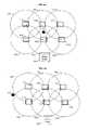
- FIG. 1is a schematic of a system 100 for one embodiment of RFID zone security.
- a plurality of RFID readers 110 1 – 110 6are used as proximity sensors to detect the presence of one or more recognized RFID tags (not shown) within a predetermine area 120 . It should be appreciated that more or fewer RFID readers may be used to cover the area 120 , and that the RFID readers may have any number of orientations.
- RFID readers 110 1 – 110 6emit RF signals having an approximate range 130 1 – 130 6 .
- the ranges 130 1 – 130 6may overlap to enable the system 100 to accurately indicate when a recognized RFID tags leaves the area 120 .
- RFID tagsbecome “recognized RFID tags” once they are serialized and programmed into the system 100 .
- RFID readers 110 1 – 110 6may then ping/poll for recognized RFID tags to ensure that they are still within area 120 . If a recognized RFID tag is removed from the area 120 , system 100 will detect this fact the next time the tags are pinged or polled. In one embodiment, an alarm or other signal may be triggered upon detecting that an RFID tag has been removed from the area 120 .
- FIG. 2is a simplified diagram of how the RFID readers 110 1 – 110 6 of FIG. 1 may be interconnected.
- RFID readers 110 1 – 110 6are connected over communication links 140 .
- communication links 140may include, but not be limited to, a telephone line, an Integrated Services Digital Network (ISDN) connection, an Asynchronous Transfer Mode (ATM) connection, a frame relay connection, an Ethernet connection, a coaxial connection, a fiber optic connection, etc.
- ISDNIntegrated Services Digital Network
- ATMAsynchronous Transfer Mode
- frame relay connectionan Ethernet connection
- coaxial connectiona fiber optic connection
- each of the RFID readers 110 1 – 110 6are shown as being connected to one other RFID reader by communication links 140 .
- the RFID readers 110 1 – 110 6may be optionally connected to additional RFID readers over optional communication links 150 .
- FIG. 2further depicts alarm logic 160 connected to the RFID readers 110 1 – 110 6 via one of the communication links 140 and the optional communication links 150 .
- the RFID readers 110 1 – 110 6send out a ping/poll for recognized RFID tags (not shown).
- the RFID tagsmay then respond to the ping/poll which will be detected by one of the RFID readers 110 1 – 110 6 so long as the tag(s) in question are within the detection area of the RFID readers 110 1 – 110 6 (e.g., area 120 ). So long as at least one of the RFID readers 110 1 – 110 6 detects the RFID tag's response, this information can be communicated to the other RFID readers 110 1 – 110 6 readers.
- this informationmay be communicated to alarm logic 160 which may in turn provide a notification that at least one of the recognized tags have moved out of the area.
- this notificationmay be an alarm or other audible sound, and/or a visual indication.
- Another aspect of the inventionis to enable the location of misplaced recognized tags. Namely, the response received from a ping or poll by the RFID readers 110 1 – 110 6 , can be used to identify in which of the ranges 130 1 – 130 6 a particular asset is located. This information may then be communicated to a central processing system or the like.
- FIG. 3is another embodiment of a simplified diagram depicting how the RFID readers 110 1 – 110 6 of FIG. 1 may be interconnected.
- no communication links 140 or optional communication links 150are needed.
- RFID readers 110 1 – 110 6are able to wirelessly communicate with each other and with alarm logic 160 .
- each of the RFID readers 110 1 – 110 6is within the range 130 1 – 130 6 of one or more of the other RFID readers 110 1 – 110 6 . This enables the RFID readers 110 1 – 110 6 to wirelessly communicate with each other, as well as with alarm logic 160 .
- wireless communicationincludes radio frequency, but may similarly include other known wireless technologies (e.g., spread spectrum).
- FIGS. 4A–4Bdepict additional embodiments of the diagram of FIG. 3 .
- a recognized RFID tag 170is oriented within the range 130 1 – 130 6 of the RFID readers 110 1 – 110 6 .
- RFID readers 110 1 – 110 6may ping/poll the tag 170 at regular intervals. So long as the tag 170 is within the range 130 1 – 130 6 of at least one RFID reader 110 1 – 110 6 , the tag's 170 response will be detected and alarm logic 160 will not be triggered. It should be appreciated that the tag's 170 response may be backscatter or energy from a discharged capacitor, where the tag 170 is a passive tag.
- tag 170is an active tag its response may comprise additional data transmitted over radio frequencies.
- RFID readers 110 1 – 110 6may communicate with each other after each ping to verify that all recognized RFID tags (e.g., tag 170 ) are within range of at least one of the RFID readers 110 1 – 110 6 .
- FIG. 4Bdepicts the diagram of FIG. 4A after the recognized tag 170 is removed from the coverage area of the RFID readers 110 1 – 110 6 .
- the next time the RFID readers 110 1 – 110 6 ping or poll the tag 170there won't be a response. This lack of a response will indicate to the system that the tag 170 has been removed.
- alarm logic 170may be activated as an indication that the tag 170 has been removed from a designated area without authorization.
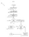
- process 500begins at block 510 with an array of RFID readers (e.g., RFID readers 110 1 – 110 6 ) being positioned and oriented to cover a predetermined area (e.g., area 120 ).
- the signal rangese.g., ranges 130 1 – 130 6
- the RFID readersoverlap such that any recognized/serialized RFID tags within the predetermined area will be properly detected.
- one or more asset tagsmay be serialized (block 520 ) and attached to corresponding assets (block 530 ).
- Serialized asset tagsare those tags which have been assigned an identification code, or other identifying information which is provided to an RFID reader when requested.
- RFID tagsmay be attached to an asset using any number of techniques, some being more secure than others. However, by fixedly attaching an RFID tag to an asset, the location of the asset can be monitored by pinging/polling the attached RFID tag.
- process 500continues to block 540 where the array of RFID readers is programmed with the serialized tags. While in one embodiment, each individual RFID reader is programmed with the serialized tags, in another embodiment a central processor, which is in communication with the array of RFID readers, may be programmed with the serialized tags. In yet another embodiment, or in addition to the previous embodiments, the array of RFID readers or the central processor are programmed with an identification code for each serialized RFID tag. However, it should be appreciated that the RFID reader or the central processor may similarly be programmed with additional information relating to the serialized RFID tags.
- the RFID readersmay ping or poll the serialized RFID tags at regular intervals (block 550 ).
- the signal sent by the tags in response to the reader pollmay be backscatter (in the case of passive tags) or an RF signal (in the case of an active tag).
- the RFID tagsshould be able to communicate back to the RFID readers some form of information which identifies the tag in question and indicates that it is still in range of at least one of the RFID readers.
- process 500moves to block 560 where a determination can be made as to whether all of the tagged assets are accounted for. In one embodiment, this is done by comparing the responses received from the RFID tags within range to the list of recognized tags that were programmed into the reader array at block 540 . If all tags are accounted for, then process 500 returns to block 550 where the asset tags can be polled again after the predetermined interval of time lapses. If, on the other hand, one or more of the assets are not accounted for (i.e., no response is detected by at least one of the RFID readers in the array), then process 500 moves to block 570 where an alarm may be sounded. Rather than sounding an alarm, it should equally be appreciated that other forms of notification may similarly be used (e.g., visual notification, other audible notification, etc.).
- Process 600begins with the asset tags being serialized (block 610 ) and attached to desired items (block 620 ). Thereafter, at block 630 , an RFID reader or central processor is programmed with the serialized tags. While in one embodiment, one or more RFID readers may be programmed with the serialized tags, in another embodiment a central processor, which is in communication with at least one RFID reader, may be programmed with the serialized tags.
- the RFID reader(s) or central processormay be programmed with an identification code for each serialized RFID tag.
- the RFID reader(s) or the central processormay similarly be programmed with additional information relating to the serialized RFID tags.
- Process 600continues with block 640 where a user can identify one or more items for replacement, as well as the time period for when the replacement should occur. For example, in one embodiment a user may identify the water filter in a refrigerator for replacement in 3 months. Similarly, batteries in a smoke detector may be designated for replacement every 12 months.
- an RFID tagmay be serialized (block 610 ) and attached to the water filter and/or batteries (block 620 ). Thereafter, the RFID reader(s) may be programmed with the serialized tags for the water filter and/or batteries (block 30 ). Then, at block 640 , the tagged water filter and/or batteries may be identified as replacement items and the replacement interval designated (i.e., 3 months and 12 months, respectively).
- this informationmay be provided to and stored by a processing unit (e.g., personal computer, PDA, etc.).
- a processing unite.g., personal computer, PDA, etc.
- the processing unitis in communication with the RFID reader which was previously programmed with the serialized water filter tag.
- process 600may continue to block 650 where a determination is made as to whether any replacement interval has lapsed. In one embodiment, this may be accomplished by having the processing unit periodically review a database of replacement items to see if any of the replacement intervals has lapsed. However, it should equally be understood that numerous other methods of determining that a replacement interval has lapsed may be used.
- process 600may continue to periodically review the list of replacement items to see if any of the replacement intervals has lapsed. If, on the other hand, a determination is made at block 650 that at least one of the replacement intervals has lapsed, process 600 will alert the user of this fact (block 660 ). In one embodiment, the processing unit may alert a user using a visual notification on a display screen or an audible notification. In another embodiment, the processing unit may communicate with another device (e.g., television) to provide the user with such notification. It should be appreciated that numerous means for notifying a user of the lapsing of a replacement interval may be apparent to one skilled in the art.
- the useris periodically (e.g., once an hour, once a day, once a week, etc.) alerted of the past-due replacement item until the tagged replacement item is polled and no response is received.
- process 600will continue to block 680 where the replacement interval is reset for the item and the process 500 returns to monitoring whether any replacement intervals have lapsed.
- a mobile RFID reader(s)is used to detect when a tagged asset is removed from the reader's range.
- an RFID readercan be incorporated into a cellular phone, PDA or the like.
- a tagged assetsuch as a piece of luggage, can then be pinged/polled by the RFID reader to detect if the luggage has been removed from the owner's possession.
- Process 700begins with one or more asset tags being serialized and attached to corresponding assets (e.g., a piece of luggage, handbag, wallet, etc.) (block 710 ). Either before or after the asset tag(s) are attached, process 700 continues to block 720 where the mobile RFID reader is programmed with the serialized asset tags.
- the RFID readermay poll the serialized RFID tag(s) at regular intervals (block 730 ).
- the signal sent by the tags in response to the reader pingsmay be backscatter (in the case of passive tags) or an RF signal (in the case of an active tag).
- the RFID tag(s)should be able to communicate back to the mobile RFID reader some form of information which identifies the tag in question and indicates that it is still in range of the mobile RFID readers.
- process 700moves to block 740 where a determination can be made as to whether all of tagged asset(s) are still within range of the mobile reader. In one embodiment, this is done by comparing the responses received from the RFID tag(s) within range to a list of the recognized tags that were programmed into the mobile reader at block 720 . If all previously-programmed tags are accounted for, then process 700 returns to block 730 where the asset tag(s) can again be polled after a predetermined interval of time lapses.
- process 700moves to block 750 where an alarm may be sounded and the owner alerted to the fact that an asset has been removed from his possession. Rather than sounding an alarm, it should equally be appreciated that other forms of notification may similarly be used (e.g., visual notification, other audible notification, etc.).
- FIG. 8depicts yet another embodiment of a process for utilizing an RFID reader as a proximity sensor.
- an RFID reader and serialized tagmay be used in combination to authorize the activation of a device, such as an automobile.
- the serialized tagmay be attached to a portable object, such as a key ring, keyless entry transmitter, a wallet, etc.
- An RFID readermay then be programmed with the serialized tag and coupled to a device that is to be activated.
- the deviceis an automobile, it should similarly be appreciated that the device may be a personal computer, PDA, cell phone, or any other device capable of being electronically activated.
- process 800begins with one or more asset tag(s) being serialized (block 810 ).
- the RFID readermay then be programmed with the serialized tag(s) at block 820 , and coupled to the device in question at block 830 .
- the RFID readeris coupled to an activation mechanism for the device (e.g., a vehicle's starter). It should be appreciated that numerous configurations for coupling the RFID reader to the device are possible, and that the RFID reader need only be configured to be able to prevent or allow the device's activation.
- process 800a determination may be made as to whether someone is attempting to activate the device (block 840 ). If not, process 800 will loop back to continue monitoring whether the device is attempting to be activated. If, on the other hand, someone is attempting to activate the device, the RFID reader will poll for the serialize tag with which it was previously programmed. If the serialized tag is not within range, the RFID reader will not detect a response and the attempted activation will be deemed unauthorized. Process 800 will continue to block 870 where the attempted activation will not be permitted. If, on the other hand, the RFID reader does receive a response from the serialized tag to the poll, this will indicate that the attempted activation is authorized and, as such, will be permitted (block 880 ).
Landscapes
- Physics & Mathematics (AREA)
- General Physics & Mathematics (AREA)
- Health & Medical Sciences (AREA)
- Child & Adolescent Psychology (AREA)
- General Health & Medical Sciences (AREA)
- Business, Economics & Management (AREA)
- Emergency Management (AREA)
- Burglar Alarm Systems (AREA)
Abstract
Description
Claims (24)
Priority Applications (1)
| Application Number | Priority Date | Filing Date | Title |
|---|---|---|---|
| US10/901,489US7187287B2 (en) | 2004-07-27 | 2004-07-27 | Systems and methods for zone security |
Applications Claiming Priority (1)
| Application Number | Priority Date | Filing Date | Title |
|---|---|---|---|
| US10/901,489US7187287B2 (en) | 2004-07-27 | 2004-07-27 | Systems and methods for zone security |
Publications (2)
| Publication Number | Publication Date |
|---|---|
| US20060022823A1 US20060022823A1 (en) | 2006-02-02 |
| US7187287B2true US7187287B2 (en) | 2007-03-06 |
Family
ID=35731506
Family Applications (1)
| Application Number | Title | Priority Date | Filing Date |
|---|---|---|---|
| US10/901,489Expired - LifetimeUS7187287B2 (en) | 2004-07-27 | 2004-07-27 | Systems and methods for zone security |
Country Status (1)
| Country | Link |
|---|---|
| US (1) | US7187287B2 (en) |
Cited By (30)
| Publication number | Priority date | Publication date | Assignee | Title |
|---|---|---|---|---|
| US20050092825A1 (en)* | 2003-11-04 | 2005-05-05 | Captech Ventures, Inc. | System and method for RFID system integration |
| US20060113302A1 (en)* | 2004-09-09 | 2006-06-01 | Inteligistics, Inc. | Modular shipping unit and system |
| US20060192652A1 (en)* | 2005-02-14 | 2006-08-31 | Inteligistics, Inc. | Identification system |
| US20060289650A1 (en)* | 2005-06-27 | 2006-12-28 | Mobile Aspects, Inc. | Networked monitoring system |
| US20070018829A1 (en)* | 2005-07-25 | 2007-01-25 | Honeywell International Inc. | Asset location system with enhanced accuracy |
| US20070194930A1 (en)* | 2006-02-21 | 2007-08-23 | International Business Machines Corporation | Method, system, and program product for automatic RFID attenuation and recovery |
| US20070290792A1 (en)* | 2006-06-12 | 2007-12-20 | Nissan Motor Co., Ltd. | Door lock mechanism controller and method of controlling door lock mechanism |
| US20080117048A1 (en)* | 2006-11-17 | 2008-05-22 | Motorola, Inc. | Method and System for Facilitating Communication Between a Radio Frequency Identification (RFID) Device and RFID Tags |
| US20090085744A1 (en)* | 2007-09-28 | 2009-04-02 | Symbol Technologies, Inc. | Rfid based network admission control |
| US20090276239A1 (en)* | 2008-04-30 | 2009-11-05 | Ecolab Inc. | Validated healthcare cleaning and sanitizing practices |
| US20100148966A1 (en)* | 2008-12-12 | 2010-06-17 | Infosys Technologies Limited | System and method for real time theft detection |
| US20100191049A1 (en)* | 2008-10-28 | 2010-07-29 | Mobile Aspects, Inc. | Endoscope Storage Cabinet, Tracking System, and Signal Emitting Member |
| US20100274640A1 (en)* | 2009-04-24 | 2010-10-28 | Ecolab Usa Inc. | Management of cleaning processes via monitoring of chemical product usage |
| US20100315244A1 (en)* | 2009-06-12 | 2010-12-16 | Ecolab USA Inc., | Hand hygiene compliance monitoring |
| US20110068923A1 (en)* | 2009-09-23 | 2011-03-24 | Microsoft Corporation | Power efficient object detection with selective polling |
| US8639527B2 (en) | 2008-04-30 | 2014-01-28 | Ecolab Usa Inc. | Validated healthcare cleaning and sanitizing practices |
| US8648699B2 (en) | 2010-07-19 | 2014-02-11 | Mobile Aspects, Inc. | Item tracking system and arrangement |
| US9224124B2 (en) | 2013-10-29 | 2015-12-29 | Mobile Aspects, Inc. | Item storage and tracking cabinet and arrangement |
| US9348013B2 (en) | 2013-09-18 | 2016-05-24 | Mobile Aspects, Inc. | Item hanger arrangement, system, and method |
| US9501917B2 (en) | 2014-12-23 | 2016-11-22 | Sami Slim | Theft deterrent device, system, and method |
| CN107134110A (en)* | 2017-06-02 | 2017-09-05 | 安庆师范大学 | Security protection and early education system and method based on technology of Internet of things |
| US9824569B2 (en) | 2011-01-28 | 2017-11-21 | Ecolab Usa Inc. | Wireless communication for dispenser beacons |
| US9892618B2 (en) | 2013-08-09 | 2018-02-13 | Mobile Aspects, Inc. | Signal emitting member attachment system and arrangement |
| US9947197B2 (en) | 2015-11-04 | 2018-04-17 | Samsung Electronics Co., Ltd. | Alerting system and method for portable electronic device |
| US10034400B2 (en) | 2013-12-04 | 2018-07-24 | Mobile Aspects, Inc. | Item storage arrangement system and method |
| US10529219B2 (en) | 2017-11-10 | 2020-01-07 | Ecolab Usa Inc. | Hand hygiene compliance monitoring |
| US11213773B2 (en) | 2017-03-06 | 2022-01-04 | Cummins Filtration Ip, Inc. | Genuine filter recognition with filter monitoring system |
| USRE48951E1 (en) | 2015-08-05 | 2022-03-01 | Ecolab Usa Inc. | Hand hygiene compliance monitoring |
| US11272815B2 (en) | 2017-03-07 | 2022-03-15 | Ecolab Usa Inc. | Monitoring modules for hand hygiene dispensers |
| US11284333B2 (en) | 2018-12-20 | 2022-03-22 | Ecolab Usa Inc. | Adaptive route, bi-directional network communication |
Families Citing this family (17)
| Publication number | Priority date | Publication date | Assignee | Title |
|---|---|---|---|---|
| US8567683B2 (en)* | 2005-02-24 | 2013-10-29 | Kyocera Corporation | Reader device and outing data carrier decision method |
| US7360701B2 (en)* | 2005-03-24 | 2008-04-22 | Ecolab Inc. | Managing maintenance of serviceable items based on unique identification labeling |
| US7671743B2 (en)* | 2006-11-03 | 2010-03-02 | International Business Machines Corporation | Detecting a departure of an RFID tag from an area |
| US7940181B2 (en)* | 2007-02-01 | 2011-05-10 | Infosys Technologies Ltd. | RFID based product level availability |
| WO2008104180A1 (en)* | 2007-03-01 | 2008-09-04 | Peter Nygaard Christiansen | Safety device |
| US20080291023A1 (en)* | 2007-05-24 | 2008-11-27 | Microsoft Corporation | RFID Discovery, Tracking, and Provisioning of Information Technology Assets |
| WO2008147244A1 (en)* | 2007-05-30 | 2008-12-04 | Motorola, Inc. | Method and system for providing vehicle security |
| US8199014B1 (en)* | 2007-06-29 | 2012-06-12 | Sony Ericsson Mobile Communications Ab | System, device and method for keeping track of portable items by means of a mobile electronic device |
| US7616093B2 (en)* | 2007-07-02 | 2009-11-10 | International Business Machines Corporation | Method and system for identifying expired RFID data |
| US8717144B2 (en)* | 2008-04-29 | 2014-05-06 | Intelleflex Corporation | RFID system with distributed readers |
| US8810392B1 (en) | 2010-02-04 | 2014-08-19 | Google Inc. | Device and method for monitoring the presence of items and issuing an alert if an item is not detected |
| US9489821B2 (en)* | 2010-02-04 | 2016-11-08 | Google Inc. | Device and method for monitoring the presence of an item |
| GB2490334B (en)* | 2011-04-26 | 2015-09-16 | Veraz Ltd | Contact monitoring system |
| EP2660788A1 (en)* | 2012-05-04 | 2013-11-06 | Plettac Electronics Sistemas, S.A. | Anti-theft asset protection system and method by means of electromagnetic confinement techniques |
| US9245160B2 (en)* | 2013-08-20 | 2016-01-26 | Qualcomm Technologies International, Ltd. | Method for setting up a beacon network inside a retail environment |
| EP3843484A1 (en) | 2015-07-13 | 2021-06-30 | Isolynx, LLC | System and method for dynamically scheduling wireless transmissions without collision |
| CN109416866A (en)* | 2016-06-21 | 2019-03-01 | 三菱电机株式会社 | Access management system |
Citations (15)
| Publication number | Priority date | Publication date | Assignee | Title |
|---|---|---|---|---|
| US5949335A (en) | 1998-04-14 | 1999-09-07 | Sensormatic Electronics Corporation | RFID tagging system for network assets |
| US5999091A (en)* | 1996-11-25 | 1999-12-07 | Highwaymaster Communications, Inc. | Trailer communications system |
| US6040774A (en)* | 1998-05-27 | 2000-03-21 | Sarnoff Corporation | Locating system and method employing radio frequency tags |
| US6263440B1 (en) | 1998-07-10 | 2001-07-17 | International Business Machines Corporation | Tracking and protection of display monitors by reporting their identity |
| US6366242B1 (en)* | 1997-01-21 | 2002-04-02 | Wherenet Corporation | Computer workstation tool for displaying performance estimate of tagged object geo-location system for proposed geometry layout of tag transmission readers |
| US6593885B2 (en)* | 2000-04-27 | 2003-07-15 | Wherenet Corp | Low cost DTOA location processing system based on multiple readers-to-single processor architecture |
| US6609656B1 (en)* | 1998-03-27 | 2003-08-26 | Micron Technology, Inc. | Method and system for identifying lost or stolen devices |
| US6681989B2 (en) | 2002-01-15 | 2004-01-27 | International Business Machines Corporation | Inventory control and point-of-sale system and method |
| US6696954B2 (en) | 2000-10-16 | 2004-02-24 | Amerasia International Technology, Inc. | Antenna array for smart RFID tags |
| US6714121B1 (en) | 1999-08-09 | 2004-03-30 | Micron Technology, Inc. | RFID material tracking method and apparatus |
| US6724308B2 (en)* | 2000-08-11 | 2004-04-20 | Escort Memory Systems | RFID tracking method and system |
| US6734797B2 (en) | 2001-02-12 | 2004-05-11 | Matrics, Inc. | Identification tag utilizing charge pumps for voltage supply generation and data recovery |
| US6784789B2 (en)* | 1999-07-08 | 2004-08-31 | Intermec Ip Corp. | Method and apparatus for verifying RFID tags |
| US6967563B2 (en)* | 1999-06-11 | 2005-11-22 | Ronald Bormaster | Inventory control system |
| US7046147B2 (en)* | 2003-08-29 | 2006-05-16 | Rf Monolithics, Inc. | Integrated security system and method |
- 2004
- 2004-07-27USUS10/901,489patent/US7187287B2/ennot_activeExpired - Lifetime
Patent Citations (15)
| Publication number | Priority date | Publication date | Assignee | Title |
|---|---|---|---|---|
| US5999091A (en)* | 1996-11-25 | 1999-12-07 | Highwaymaster Communications, Inc. | Trailer communications system |
| US6366242B1 (en)* | 1997-01-21 | 2002-04-02 | Wherenet Corporation | Computer workstation tool for displaying performance estimate of tagged object geo-location system for proposed geometry layout of tag transmission readers |
| US6609656B1 (en)* | 1998-03-27 | 2003-08-26 | Micron Technology, Inc. | Method and system for identifying lost or stolen devices |
| US5949335A (en) | 1998-04-14 | 1999-09-07 | Sensormatic Electronics Corporation | RFID tagging system for network assets |
| US6040774A (en)* | 1998-05-27 | 2000-03-21 | Sarnoff Corporation | Locating system and method employing radio frequency tags |
| US6263440B1 (en) | 1998-07-10 | 2001-07-17 | International Business Machines Corporation | Tracking and protection of display monitors by reporting their identity |
| US6967563B2 (en)* | 1999-06-11 | 2005-11-22 | Ronald Bormaster | Inventory control system |
| US6784789B2 (en)* | 1999-07-08 | 2004-08-31 | Intermec Ip Corp. | Method and apparatus for verifying RFID tags |
| US6714121B1 (en) | 1999-08-09 | 2004-03-30 | Micron Technology, Inc. | RFID material tracking method and apparatus |
| US6593885B2 (en)* | 2000-04-27 | 2003-07-15 | Wherenet Corp | Low cost DTOA location processing system based on multiple readers-to-single processor architecture |
| US6724308B2 (en)* | 2000-08-11 | 2004-04-20 | Escort Memory Systems | RFID tracking method and system |
| US6696954B2 (en) | 2000-10-16 | 2004-02-24 | Amerasia International Technology, Inc. | Antenna array for smart RFID tags |
| US6734797B2 (en) | 2001-02-12 | 2004-05-11 | Matrics, Inc. | Identification tag utilizing charge pumps for voltage supply generation and data recovery |
| US6681989B2 (en) | 2002-01-15 | 2004-01-27 | International Business Machines Corporation | Inventory control and point-of-sale system and method |
| US7046147B2 (en)* | 2003-08-29 | 2006-05-16 | Rf Monolithics, Inc. | Integrated security system and method |
Cited By (48)
| Publication number | Priority date | Publication date | Assignee | Title |
|---|---|---|---|---|
| US7267275B2 (en)* | 2003-11-04 | 2007-09-11 | Captech Ventures, Inc. | System and method for RFID system integration |
| US20050092825A1 (en)* | 2003-11-04 | 2005-05-05 | Captech Ventures, Inc. | System and method for RFID system integration |
| US20060113302A1 (en)* | 2004-09-09 | 2006-06-01 | Inteligistics, Inc. | Modular shipping unit and system |
| US7978060B2 (en) | 2005-02-14 | 2011-07-12 | Inteligistics, Inc. | Identification system |
| US20060192652A1 (en)* | 2005-02-14 | 2006-08-31 | Inteligistics, Inc. | Identification system |
| US20060289650A1 (en)* | 2005-06-27 | 2006-12-28 | Mobile Aspects, Inc. | Networked monitoring system |
| US20070018829A1 (en)* | 2005-07-25 | 2007-01-25 | Honeywell International Inc. | Asset location system with enhanced accuracy |
| US7333018B2 (en)* | 2005-07-25 | 2008-02-19 | Honeywell International Inc. | Asset location system with enhanced accuracy |
| US20070194930A1 (en)* | 2006-02-21 | 2007-08-23 | International Business Machines Corporation | Method, system, and program product for automatic RFID attenuation and recovery |
| US8305218B2 (en) | 2006-02-21 | 2012-11-06 | International Business Machines Corporation | System and program product for automatic RFID attenuation and recovery |
| US7439864B2 (en)* | 2006-02-21 | 2008-10-21 | International Business Machines Corporation | Method for automatic RFID attenuation and recovery |
| US20090051495A1 (en)* | 2006-02-21 | 2009-02-26 | Hunt Christian L | System and program product for automatic rfid attentuation and recovery |
| US7902960B2 (en)* | 2006-06-12 | 2011-03-08 | Nissan Motor Co., Ltd. | Door lock mechanism controller and method of controlling door lock mechanism |
| US20070290792A1 (en)* | 2006-06-12 | 2007-12-20 | Nissan Motor Co., Ltd. | Door lock mechanism controller and method of controlling door lock mechanism |
| US20080117048A1 (en)* | 2006-11-17 | 2008-05-22 | Motorola, Inc. | Method and System for Facilitating Communication Between a Radio Frequency Identification (RFID) Device and RFID Tags |
| US20090085744A1 (en)* | 2007-09-28 | 2009-04-02 | Symbol Technologies, Inc. | Rfid based network admission control |
| US8051466B2 (en)* | 2007-09-28 | 2011-11-01 | Symbol Technologies, Inc. | RFID based network admission control |
| US8639527B2 (en) | 2008-04-30 | 2014-01-28 | Ecolab Usa Inc. | Validated healthcare cleaning and sanitizing practices |
| US8990098B2 (en) | 2008-04-30 | 2015-03-24 | Ecolab Inc. | Validated healthcare cleaning and sanitizing practices |
| US20090276239A1 (en)* | 2008-04-30 | 2009-11-05 | Ecolab Inc. | Validated healthcare cleaning and sanitizing practices |
| US8992416B2 (en) | 2008-10-28 | 2015-03-31 | Mobile Aspects, Inc. | Endoscope storage cabinet, tracking system, and signal emitting member |
| US20100191049A1 (en)* | 2008-10-28 | 2010-07-29 | Mobile Aspects, Inc. | Endoscope Storage Cabinet, Tracking System, and Signal Emitting Member |
| US8414471B2 (en) | 2008-10-28 | 2013-04-09 | Mobile Aspects, Inc. | Endoscope storage cabinet, tracking system, and signal emitting member |
| US8427319B2 (en) | 2008-12-12 | 2013-04-23 | Infosys Technologies Limited | System and method for real time theft detection |
| US20100148966A1 (en)* | 2008-12-12 | 2010-06-17 | Infosys Technologies Limited | System and method for real time theft detection |
| US20100274640A1 (en)* | 2009-04-24 | 2010-10-28 | Ecolab Usa Inc. | Management of cleaning processes via monitoring of chemical product usage |
| US8395515B2 (en) | 2009-06-12 | 2013-03-12 | Ecolab Usa Inc. | Hand hygiene compliance monitoring |
| US20100315244A1 (en)* | 2009-06-12 | 2010-12-16 | Ecolab USA Inc., | Hand hygiene compliance monitoring |
| US8502680B2 (en) | 2009-06-12 | 2013-08-06 | Ecolab Usa Inc. | Hand hygiene compliance monitoring |
| US8144015B2 (en) | 2009-09-23 | 2012-03-27 | Microsoft Corporation | Power efficient object detection with selective polling |
| US20110068923A1 (en)* | 2009-09-23 | 2011-03-24 | Microsoft Corporation | Power efficient object detection with selective polling |
| US8648699B2 (en) | 2010-07-19 | 2014-02-11 | Mobile Aspects, Inc. | Item tracking system and arrangement |
| US9824569B2 (en) | 2011-01-28 | 2017-11-21 | Ecolab Usa Inc. | Wireless communication for dispenser beacons |
| US9892618B2 (en) | 2013-08-09 | 2018-02-13 | Mobile Aspects, Inc. | Signal emitting member attachment system and arrangement |
| US9348013B2 (en) | 2013-09-18 | 2016-05-24 | Mobile Aspects, Inc. | Item hanger arrangement, system, and method |
| US9224124B2 (en) | 2013-10-29 | 2015-12-29 | Mobile Aspects, Inc. | Item storage and tracking cabinet and arrangement |
| US10034400B2 (en) | 2013-12-04 | 2018-07-24 | Mobile Aspects, Inc. | Item storage arrangement system and method |
| US9501917B2 (en) | 2014-12-23 | 2016-11-22 | Sami Slim | Theft deterrent device, system, and method |
| USRE48951E1 (en) | 2015-08-05 | 2022-03-01 | Ecolab Usa Inc. | Hand hygiene compliance monitoring |
| US9947197B2 (en) | 2015-11-04 | 2018-04-17 | Samsung Electronics Co., Ltd. | Alerting system and method for portable electronic device |
| US11213773B2 (en) | 2017-03-06 | 2022-01-04 | Cummins Filtration Ip, Inc. | Genuine filter recognition with filter monitoring system |
| US11272815B2 (en) | 2017-03-07 | 2022-03-15 | Ecolab Usa Inc. | Monitoring modules for hand hygiene dispensers |
| US11903537B2 (en) | 2017-03-07 | 2024-02-20 | Ecolab Usa Inc. | Monitoring modules for hand hygiene dispensers |
| US12390056B2 (en) | 2017-03-07 | 2025-08-19 | Ecolab Usa Inc. | Monitoring modules for hand hygiene dispensers |
| CN107134110A (en)* | 2017-06-02 | 2017-09-05 | 安庆师范大学 | Security protection and early education system and method based on technology of Internet of things |
| US10529219B2 (en) | 2017-11-10 | 2020-01-07 | Ecolab Usa Inc. | Hand hygiene compliance monitoring |
| US11284333B2 (en) | 2018-12-20 | 2022-03-22 | Ecolab Usa Inc. | Adaptive route, bi-directional network communication |
| US11711745B2 (en) | 2018-12-20 | 2023-07-25 | Ecolab Usa Inc. | Adaptive route, bi-directional network communication |
Also Published As
| Publication number | Publication date |
|---|---|
| US20060022823A1 (en) | 2006-02-02 |
Similar Documents
| Publication | Publication Date | Title |
|---|---|---|
| US7187287B2 (en) | Systems and methods for zone security | |
| US7420458B1 (en) | Secondary card reader | |
| US7859404B2 (en) | Method and apparatus for proximity activated RFID system | |
| US7002473B2 (en) | Loss prevention system | |
| US8264356B2 (en) | EAS alarming tag with RFID features | |
| US7034684B2 (en) | Personal item monitor using radio frequency identification | |
| US7956746B2 (en) | Wireless tracking system and method with tag removal detection | |
| US9330287B2 (en) | Real-time asset tracking and event association | |
| US7872578B2 (en) | Tracking, identification, and security system for a portable device | |
| US20050262751A1 (en) | Method and apparatus for detecting and identifying firearms | |
| US7202784B1 (en) | Anti-jamming detector for radio frequency identification systems | |
| US20060232398A1 (en) | System for personal possessions security | |
| US20070046439A1 (en) | Radio frequency identification system with device for protecting privacy and method of operation | |
| US9830443B2 (en) | Device and method for controlling access to at least one machine | |
| EP1554703B1 (en) | Wireless security beacon for consumer equipment | |
| US7271718B2 (en) | Protection against loss or theft of identification badges and other items | |
| CA2729689C (en) | Security system and method for using an lf activated rfid tag | |
| RU2470372C2 (en) | Alarm signalling method based on monitoring proximity of receiving and transmitting radio devices | |
| US20100259389A1 (en) | Forgetmenot, radio-frequency identification (RFID) system with verifying interconnected units | |
| US20110084837A1 (en) | Security systems and methods | |
| US20230195203A1 (en) | Method and apparatus for reducing power consumption in a hardware token reader | |
| CA2529618A1 (en) | Loss prevention system | |
| WO2008044048A1 (en) | Portable security system | |
| HK1169880A (en) | Eas alarming tag with rfid features and method thereof | |
| HK1169880B (en) | Eas alarming tag with rfid features and method thereof |
Legal Events
| Date | Code | Title | Description |
|---|---|---|---|
| AS | Assignment | Owner name:SONY CORPORATION, JAPAN Free format text:ASSIGNMENT OF ASSIGNORS INTEREST;ASSIGNOR:RYAL, KIM ANNON;REEL/FRAME:015636/0812 Effective date:20040722 Owner name:SONY ELECTRONICS INC., A DELAWARE CORPORATION, NEW Free format text:ASSIGNMENT OF ASSIGNORS INTEREST;ASSIGNOR:RYAL, KIM ANNON;REEL/FRAME:015636/0812 Effective date:20040722 | |
| AS | Assignment | Owner name:SONY CORPORATION, JAPAN Free format text:CORRECTIVE ASSIGNMENT TO CORRECT THE NOTATION "A DELAWARE CORPORATION" BE DELETED FROM THE RECORDED (2) ASSIGNEE NAME SONY ELECTRONICS INC. PREVIOUSLY RECORDED ON REEL 015636 FRAME 0812;ASSIGNOR:RYAL, KIM ANNON;REEL/FRAME:018417/0953 Effective date:20040722 Owner name:SONY ELECTRONICS INC., NEW JERSEY Free format text:CORRECTIVE ASSIGNMENT TO CORRECT THE NOTATION "A DELAWARE CORPORATION" BE DELETED FROM THE RECORDED (2) ASSIGNEE NAME SONY ELECTRONICS INC. PREVIOUSLY RECORDED ON REEL 015636 FRAME 0812;ASSIGNOR:RYAL, KIM ANNON;REEL/FRAME:018417/0953 Effective date:20040722 | |
| STCF | Information on status: patent grant | Free format text:PATENTED CASE | |
| FPAY | Fee payment | Year of fee payment:4 | |
| FPAY | Fee payment | Year of fee payment:8 | |
| AS | Assignment | Owner name:SONY CORPORATION, JAPAN Free format text:ASSIGNMENT OF ASSIGNORS INTEREST;ASSIGNOR:SONY ELECTRONICS INC.;REEL/FRAME:036330/0420 Effective date:20150731 | |
| MAFP | Maintenance fee payment | Free format text:PAYMENT OF MAINTENANCE FEE, 12TH YEAR, LARGE ENTITY (ORIGINAL EVENT CODE: M1553); ENTITY STATUS OF PATENT OWNER: LARGE ENTITY Year of fee payment:12 |