US7186256B2 - Dynamic, modular, single-lock anterior cervical plate system having assembleable and movable segments - Google Patents
Dynamic, modular, single-lock anterior cervical plate system having assembleable and movable segmentsDownload PDFInfo
- Publication number
- US7186256B2 US7186256B2US10/160,062US16006202AUS7186256B2US 7186256 B2US7186256 B2US 7186256B2US 16006202 AUS16006202 AUS 16006202AUS 7186256 B2US7186256 B2US 7186256B2
- Authority
- US
- United States
- Prior art keywords
- plate
- segments
- bone screw
- vertebral bodies
- bone
- Prior art date
- Legal status (The legal status is an assumption and is not a legal conclusion. Google has not performed a legal analysis and makes no representation as to the accuracy of the status listed.)
- Expired - Fee Related
Links
Images


Classifications
- A—HUMAN NECESSITIES
- A61—MEDICAL OR VETERINARY SCIENCE; HYGIENE
- A61B—DIAGNOSIS; SURGERY; IDENTIFICATION
- A61B17/00—Surgical instruments, devices or methods
- A61B17/56—Surgical instruments or methods for treatment of bones or joints; Devices specially adapted therefor
- A61B17/58—Surgical instruments or methods for treatment of bones or joints; Devices specially adapted therefor for osteosynthesis, e.g. bone plates, screws or setting implements
- A61B17/68—Internal fixation devices, including fasteners and spinal fixators, even if a part thereof projects from the skin
- A61B17/80—Cortical plates, i.e. bone plates; Instruments for holding or positioning cortical plates, or for compressing bones attached to cortical plates
- A61B17/8004—Cortical plates, i.e. bone plates; Instruments for holding or positioning cortical plates, or for compressing bones attached to cortical plates with means for distracting or compressing the bone or bones
- A61B17/8009—Cortical plates, i.e. bone plates; Instruments for holding or positioning cortical plates, or for compressing bones attached to cortical plates with means for distracting or compressing the bone or bones the plate having a ratchet
- A—HUMAN NECESSITIES
- A61—MEDICAL OR VETERINARY SCIENCE; HYGIENE
- A61B—DIAGNOSIS; SURGERY; IDENTIFICATION
- A61B17/00—Surgical instruments, devices or methods
- A61B17/56—Surgical instruments or methods for treatment of bones or joints; Devices specially adapted therefor
- A61B17/58—Surgical instruments or methods for treatment of bones or joints; Devices specially adapted therefor for osteosynthesis, e.g. bone plates, screws or setting implements
- A61B17/68—Internal fixation devices, including fasteners and spinal fixators, even if a part thereof projects from the skin
- A61B17/70—Spinal positioners or stabilisers, e.g. stabilisers comprising fluid filler in an implant
- A61B17/7059—Cortical plates
- A—HUMAN NECESSITIES
- A61—MEDICAL OR VETERINARY SCIENCE; HYGIENE
- A61B—DIAGNOSIS; SURGERY; IDENTIFICATION
- A61B17/00—Surgical instruments, devices or methods
- A61B17/56—Surgical instruments or methods for treatment of bones or joints; Devices specially adapted therefor
- A61B17/58—Surgical instruments or methods for treatment of bones or joints; Devices specially adapted therefor for osteosynthesis, e.g. bone plates, screws or setting implements
- A61B17/68—Internal fixation devices, including fasteners and spinal fixators, even if a part thereof projects from the skin
- A61B17/80—Cortical plates, i.e. bone plates; Instruments for holding or positioning cortical plates, or for compressing bones attached to cortical plates
- A61B17/8004—Cortical plates, i.e. bone plates; Instruments for holding or positioning cortical plates, or for compressing bones attached to cortical plates with means for distracting or compressing the bone or bones
- A61B17/8019—Cortical plates, i.e. bone plates; Instruments for holding or positioning cortical plates, or for compressing bones attached to cortical plates with means for distracting or compressing the bone or bones where the means are a separate tool rather than being part of the plate
- A—HUMAN NECESSITIES
- A61—MEDICAL OR VETERINARY SCIENCE; HYGIENE
- A61B—DIAGNOSIS; SURGERY; IDENTIFICATION
- A61B17/00—Surgical instruments, devices or methods
- A61B17/56—Surgical instruments or methods for treatment of bones or joints; Devices specially adapted therefor
- A61B17/58—Surgical instruments or methods for treatment of bones or joints; Devices specially adapted therefor for osteosynthesis, e.g. bone plates, screws or setting implements
- A61B17/68—Internal fixation devices, including fasteners and spinal fixators, even if a part thereof projects from the skin
- A61B17/80—Cortical plates, i.e. bone plates; Instruments for holding or positioning cortical plates, or for compressing bones attached to cortical plates
- A61B17/8023—Variable length plates adjustable in both directions
- A—HUMAN NECESSITIES
- A61—MEDICAL OR VETERINARY SCIENCE; HYGIENE
- A61B—DIAGNOSIS; SURGERY; IDENTIFICATION
- A61B17/00—Surgical instruments, devices or methods
- A61B17/56—Surgical instruments or methods for treatment of bones or joints; Devices specially adapted therefor
- A61B17/58—Surgical instruments or methods for treatment of bones or joints; Devices specially adapted therefor for osteosynthesis, e.g. bone plates, screws or setting implements
- A61B17/68—Internal fixation devices, including fasteners and spinal fixators, even if a part thereof projects from the skin
- A61B17/80—Cortical plates, i.e. bone plates; Instruments for holding or positioning cortical plates, or for compressing bones attached to cortical plates
- A61B17/8033—Cortical plates, i.e. bone plates; Instruments for holding or positioning cortical plates, or for compressing bones attached to cortical plates having indirect contact with screw heads, or having contact with screw heads maintained with the aid of additional components, e.g. nuts, wedges or head covers
- A61B17/8042—Cortical plates, i.e. bone plates; Instruments for holding or positioning cortical plates, or for compressing bones attached to cortical plates having indirect contact with screw heads, or having contact with screw heads maintained with the aid of additional components, e.g. nuts, wedges or head covers the additional component being a cover over the screw head
Definitions
- the fusion processoccurs in part through a process called “creeping substitution” by which new living bone replaces the dead bone such as that of a bone graft.
- the fusion processinvolves a phase of bone resorption as preliminary to the formation of the new bone. It is possible then for the bone resorption to result in gaps in the continuity of the fusion mass, such that if the hardware is sufficiently rigid, such as occurs as a result of increasing the strength of the components and constraining the relationship of the screws to the plate, those gaps may persist and increase in size as the hardware holds the bone portions separated rather than allowing those bone portions to move together to close those gaps. This holding apart of the bone portions (called distraction) can therefore lead to a failure of fusion (pseudoarthrosis).
- These rigid systemsby a combination of not inducing compression at the fusion site and of holding the bone portions to be fused apart may cause a “distraction pseudoarthrosis.”
- Alternative cervical plating systemshave attempted to prevent distraction pseudoarthrosis by allowing the vertebral bodies to collapse towards each other as needed during the fusion process. Generally this has been done by allowing the bone screws to be free to move relative to the plate, that is, movement such as sliding, swiveling, rotating, and angulating, independent of whether the screws are prevented from separating or backing out of the plates such as by the use of locks. Undesired multidirectional instability can occur in such plating systems that is counter to the very purpose of such hardware which is to increase or provide for stability.
- an improved anterior cervical plating systemthat is: (1) sufficiently rigid to maintain the desired alignment of the vertebral bodies to be fused; (2) capable of inducing compressive load across the fusion site; and/or (3) capable of allowing for the motion of the vertebral bodies towards each other to prevent or to close any gaps in the continuity of the fusion construct, while still being capable of preventing motion in all other directions.
- the solutioninvolved anchoring the bone screws through the far cortex of the bone portions to be joined, in effect anchoring the screws in such a way as to make it possible for the screws to force movement of the plates.
- the size of the vertebral bodies and the spacing between the vertebral bodiesvaries from patient to patient.
- the height of the vertebral bodies and the discs therebetweenmay vary level by level even in the same person.
- a plate of correct lengthdoes not necessarily have bone screw receiving holes correctly positioned to overlie the vertebral bodies in accordance with the spacing of the vertebral bodies to which the plate is to be applied.
- conventional plating systems of the pasthad to be manufactured in many different lengths and spacing configurations which were nevertheless fixed in an attempt to provide plates for many, though still possibly not all, of the various sizes and spacings of the vertebral bodies to which the plate was to be applied.
- the length of the platewould need to correspond to the overall length of the vertebral bodies to be joined and actual distances therebetween and the screw holes of the plate arranged to overlie the vertebral bodies.
- health care facilitieswould need to carry a large inventory of different sizes of plates, in some cases as many as sixty different sized plates would be needed.
- Such a large inventoryis an expensive undertaking and still worse, facilities with a high caseload need to invest in more than one of each plate size to provide for the possibility of overlapping demand for the same plate size.
- Facilities with lower caseloadsmay find it prohibitively expensive to stock an inventory of plates sufficient to cover the range of possible sizes and thus might not be able to afford to stock a set at all or have less than all sizes of plates needed for all cases.
- Manufacturescannot afford to place a set of plates on consignment in facilities with low caseloads as the number of sales would not cover the carrying costs of the plates.
- an improved anterior cervical plating systemthat (1) allows for the overall adjustability of the length of the plate; (2) allows for variations in spacing between the bone screw receiving holes of the plate portions corresponding to the attachment point of the plate to the vertebral bodies; (3) reduces the requisite plate inventory; and (4) can avoid or prevent distraction pseudoarthrosis without itself introducing multidirectional instability.
- the present inventionis a dynamic, modular anterior cervical plating system including a plate comprising assembleable segments in moveable relationship to each other adapted to allow for the overall adjustability of the length of the plate and for variations in the intersegmental spacing of the bone screw receiving holes, create and/or store a compressive load across a disc space between two adjacent vertebral bodies to be fused, and/or allow motion of the vertebral bodies toward each other to prevent or close gaps in the continuity of a fusion construct, while preferably preventing motion in all other directions when in use.
- a spinal fusion segmentis defined as two vertebral bodies with an intervertebral implant, made of bone or an artificial material, in the disc space therebetween.
- a fusion constructis defined as a spinal fusion segment plus the hardware, such as a plate and screws for example.
- Dynamizationmay be “passive” allowing the plate to shorten when a shortening force, such as a compressive load is applied. Dynamization may be “active” wherein the plating system stores energy to induce shortening of the fusion construct should the opportunity present.
- the present invention plating systemmay passively dynamize, actively dynamize, provide a combination of both, as well as convert and store certain compressive stresses encountered during the healing phase as will be more fully described herein.
- the plate segmentscan also be moved to vary the spacing between the plate segments as well as the overall length of the plate so that the size of the plate may be adjusted to correspond to a range of sizes and spacing of the adjacent vertebral bodies to which the plate is being applied thereby greatly reducing the inventory of plate sizes needed.
- the moveable plate segmentscombine to form the plate.
- Each plate segmentis attached to a vertebral body to be fused by at least one bone screw and preferably a pair of bone screws, which when inserted, are preferably prevented from backing out of the plate by locking elements, one locking element per bone screw.
- the paths of the bone screws through the platemay be fixed or variable. If the paths are variable, they may be more or less stable depending on how resistant to motion the screws are relative to the plate when the screws are locked to the plate. To the extent that screws are sufficiently stable in relation to the plate to make use of the present inventive teaching, these screw, plate, and lock combinations or variations thereon are also within the broad scope of the present invention.
- the plateis capable of movement from a first or elongated position to a second or shorter position, a process generally referred to as “passive dynamization”—that is the ability of the system to allow the plated spinal segment to shorten in response to unmet compressive loads to allow for the bone portions to be fused to move close together to restore contact.
- Passive dynamizationthat is the ability of the system to allow the plated spinal segment to shorten in response to unmet compressive loads to allow for the bone portions to be fused to move close together to restore contact.
- a preferred embodiment of this present inventionis capable of allowing for this passive dynamization while preventing undesirable motions along and around all axes other than the motion along the longitudinal axis of the plate.
- the plate segmentsare articulated in such a way that even the one freedom of movement that is along the longitudinal axis of the plate is selectively limited to the desired passive dynamization—that is shortening of the plate construct.
- This preferred embodiment of the present inventionwill shorten as required to maintain loaded contact of the bone portions to be fused, and if challenged, resist any forces such as those that would accompany cervical extension that would distract or destabilize the construct by elongating it.
- a further benefit of this embodimentis its ability to store and impart a compressive load across the fusion site referred to herein as “active dynamization” wherein energy stored in the system shortens the plate construct if conditions permit.
- This loadcan be applied by the surgeon at the time of surgery and/or be produced during the healing phase by harnessing the compressive loads such as occur randomly with neck motion.
- Compressive load within a physiological rangehas been shown to have a beneficial effect on the healing of bone.
- the induction of a compressive load across vertebral bodies to be fusedinduces bone growth and when bone resorption occurs at the interface of the graft or implant and the vertebral bodies to be joined, those vertebral bodies are urged to move closer together, thus avoiding the formation of a gap therebetween and thereby acting to mitigate against pseudoarthrosis.
- various embodiments of the present inventionallow the surgeon to induce a desired amount of preload (compressive force) across the fusion site and to permit a desired amount of shortening of the construct—“active dynamization” should the opportunity occur; and yet lock the system to prevent any further shortening as might present a risk of deformity or be otherwise undesirable.
- a desired amount of preloadcompresses the construct into a desired amount of preload across the fusion site.
- a pre-load forcecan be applied to the plate segments such that while the plate segments may undergo no added motion initially, there is a selective force applied to the plate segments and the plate segments are capable of motion in only one direction, such that should resorption occur at one of the fusion interfaces then the plate segments are not only free to move in a direction toward one another, and only in that direction, but are also urged to do so to relieve that preload force.
- a systemurges the vertebral bodies together over time as resorption permits.
- a desired amount of preloadmay be induced across the fusion site to permit active dynamization should the opportunity occur, without locking the system such that after active dynamization is exhausted (if exhausted), then the plate will still allow passive dynamization to occur thereafter.
- the platein another embodiment, includes a structural feature such as a groove, recess, slot, cam, or pivot, within its physical perimeter to engage a tool to cooperatively move segments of the plate towards each other.
- a structural featuresuch as a groove, recess, slot, cam, or pivot, within its physical perimeter to engage a tool to cooperatively move segments of the plate towards each other.
- These embodiments of the present inventionmay be adapted to allow for passive, active, or active plus passive dynamization, and when used to store compressive load to allow for or prevent further motion thereafter.
- the structural feature contained within the plate for generating the compressive load and/or shortening the platemay also serve as the locking mechanism to limit the amount of further shortening possible.
- the plate of the present inventionincludes multiple segments of varying sizes wherein the segments are adapted to be assembled according to the size and spacing of the vertebral bodies to which the plate is to be applied.
- the platemay have its segments moved so that the spacing between the plate segments may be further adjusted so as to correspond to the actual distances between the vertebral bodies to be fused in a multi-segment construct for a more precise fit.
- the height of the discs and the vertebral bodiesmay vary level by level even in the same person.
- the fasteners that link the segmentscan be tightened to lock the segments after they are compressed or, alternatively, can allow for further motion of the plate segments together.
- the same hardwarecan provide for passive dynamization or be rigidly fixed depending on the fasteners used to link plate segments.
- the systemcan allow for passive dynamization, active dynamization, the combination of passive and active dynamization, or can convert body motion into active dynamization.
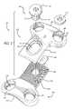
- FIG. 1is an exploded top perspective view of a plate, a fastener, and a locking element in accordance with a preferred embodiment of the present invention.
- FIG. 2is an exploded bottom perspective view of the plate, fastener, and locking element of FIG. 1 .
- FIG. 3is a top plan view of the plate, fastener, and locking element of FIG. 1 .
- FIG. 4is a bottom plan view of the plate, fastener, and locking element of FIG. 1 .
- FIG. 5is an end view of the plate of FIG. 1 .
- FIG. 6is a side elevation view of the plate of FIG. 1 .
- FIG. 7is a partial cross sectional view of the plate of FIG. 1 .
- FIG. 8is an enlarged fragmentary view of the plate of FIG. 1 and an alternative embodiment of a fastener in accordance with the present invention.
- FIG. 9is an enlarged fragmentary cross sectional view of an embodiment of the ratchetings in the upper and lower portions of the plate of FIG. 1 in a first position.
- FIG. 10is a fragmentary cross sectional view of FIG. 9 in a second position.
- FIG. 11is an enlarged fragmentary cross sectional view of a preferred embodiment of the ratchetings in the upper and lower portions of the plates of the present invention in a first position.
- FIG. 12is a fragmentary cross sectional view of FIG. 11 in a second position.
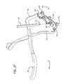
- FIG. 13is a top perspective view of the plate and fastener of FIG. 1 and instrumentation for compressing the plate and instrumentation for locking the fastener in accordance with a preferred embodiment of the present invention.
- FIG. 14is a top plan view of the plate and fastener of FIG. 1 in a compressed state with the instrumentation of FIG. 13 shown in cross section engaging the ends of the plate to compress the plate in the direction of the arrows and with the instrumentation engaging the fastener.
- FIG. 15is a partial cross sectional view along line 15 — 15 of FIG. 14 .
- FIG. 16is a top perspective view of a plate, a fastener, and a locking element in accordance with another preferred embodiment of the present invention.
- FIG. 17is a top plan view of the plate and fastener of FIG. 16 .
- FIG. 18is a top plan view of the plate of FIG. 16 in an elongated state and a fastener.
- FIG. 19is a bottom plan view of the plate and fastener of FIG. 16 .
- FIG. 20is a partial cross sectional view along line 20 — 20 of the plate of FIG. 17 .
- FIG. 21is an exploded top perspective view of the plate, fastener, and locking element of FIG. 16 .
- FIG. 22is an exploded bottom perspective view of the plate and fastener of FIG. 16 .
- FIG. 23is a top plan view of the plate and fastener of FIG. 16 and a partial fragmentary perspective view of an instrument for compressing the plate and securing the fastener in accordance with another preferred embodiment of the present invention.
- FIG. 24is an enlarged cross sectional view of the plate of FIG. 16 with the instrument of FIG. 23 engaging the fastener and positioned within the plate.
- FIG. 25is a fragmentary top plan view of the plate of FIG. 16 in an elongated state with the instrument of FIG. 23 shown in cross section engaging the fastener and positioned within the plate.
- FIG. 26is a fragmentary top plan view of the plate of FIG. 16 in a compressed state with the instrument of FIG. 23 shown in cross section engaging the fastener and positioned within the plate to rotate the fastener in the direction of the arrow to compress the plate.
- FIG. 27is an exploded top perspective view of a plate, a fastener, and a locking element in accordance with another preferred embodiment of the present invention.
- FIG. 28is a cross sectional view transverse to the longitudinal axis of the plate of FIG. 27 .
- FIG. 29is a top plan view of a plate, fasteners, and a locking element in accordance with another preferred embodiment of the present invention.
- FIG. 30is an exploded top perspective view of the plate, fasteners, and locking element of FIG. 29 .
- FIG. 31is an exploded bottom perspective view of the plate, fasteners, and locking element of FIG. 29 .
- FIG. 32is a top plan view of the plate, fasteners, and locking element of FIG. 29 .
- FIG. 33is a bottom plan view of the plate, fasteners, and locking element of FIG. 29 .
- FIG. 34is a side elevation view of the plate of FIG. 29 .
- FIG. 35is a partial cross sectional view along the longitudinal axis of the plate of FIG. 29 .
- FIG. 36is a top plan view of the plate in an elongated position, fasteners, and locking element of FIG. 29 .
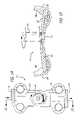
- FIG. 37is a top perspective view of the plate of FIG. 29 and another preferred embodiment of instrumentation for compressing the plate and instrumentation for locking the fastener in accordance with the present invention.
- FIG. 38is a top plan view of the plate of FIG. 29 in a compressed state with the instrumentation of FIG. 37 shown in cross section engaging the ends of the plate to compress the plate in the direction of the arrows, an alternative embodiment of instrumentation for engaging an intermediary portion of the plate to compress the plate in the direction of the arrows in dotted line, and instrumentation engaging the fastener and positioned within the plate.
- FIG. 39is a side elevation view of the plate of FIG. 38 with the instrumentation shown in partial fragmentary, hidden line, and cross sectional views.
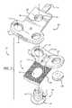
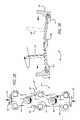
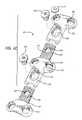
- FIG. 40is an exploded top perspective view of a plate, fasteners, and locking element in accordance with another preferred embodiment of the present invention.
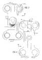
- FIG. 41 ais an enlarged fragmentary cross sectional view of a locking element and bone screw in accordance with a preferred embodiment of the present invention.
- FIG. 41 bis an enlarged fragmentary cross sectional view of a locking element and bone screw in accordance with another preferred embodiment of the present invention.
- FIG. 41 cis an enlarged fragmentary cross sectional view of a locking element and bone screw in accordance with yet another embodiment of the present invention.
- FIG. 41 dis an enlarged fragmentary cross sectional view of the locking element and bone screw of FIG. 41 c in an angled position.
- FIG. 41 eis an enlarged fragmentary cross sectional view of a self-locking bone screw in accordance with a further embodiment of the present invention.
- the present inventionis for use in the cervical spine where dynamization is highly desired to prevent distraction pseudoarthrosis and to maintain a compressive load across the fusion interfaces.
- the present inventionin one preferred embodiment is directed to a cervical plate generally having at least two movable segments that are attached to the vertebral bodies to be fused and connected in such a way as to permit dynamization of the vertebral bodies preferably along the longitudinal axis of the plate.
- the movement of the segments relative to one anothermay be accompanied by a reduction in the overall length of the plate.
- FIGS. 1–7show a preferred embodiment of a cervical plate 100 in accordance with the present invention.
- Plate 100is preferably formed of a first segment 102 and a second segment 104 in moveable relationship to one another.
- First and second segments 102 , 104can be of various lengths and/or configurations such that when the segments are assembled preferably overlapping at least in part, plates of various lengths and/or configurations can be formed to cover a range of sizes.
- First and second segments 102 , 104can be of the same or different lengths and can be coupled to each other or to an intermediate segment as shown in FIGS. 29–40 and described below in connection with other preferred embodiments of the present invention.
- the overall length of plate 100 and the spacing of segments 102 , 104can be adjusted by moving segments 102 , 104 relative to one another.
- a detachable fastener 106couples together first and second segments 102 , 104 .
- Fastener 106is configured to be detachably attached to at least one of first and second segments 102 , 104 to permit the assembly of two or more segments.
- Fastener 106is detachable to permit complete separation of first and second segments 102 , 104 from one another and assembly of the segments as desired.
- “detachable fastener”is defined as a fastener that once attached is meant to be removed and then reattached.
- fastener 106may be embodied in the form of a screw having a head 108 and a shaft 112 having a thread 116 .
- fastener 106 ′may be configured to be tightened to only one of first and second plate segments 102 , 104 so as to permit movement of first and second segments 102 , 104 relative to one another when fastener 106 ′ is fully tightened.
- fastener 106 ′may have a shoulder 110 adapted to bear upon second segment 104 as indicated by arrow C. Shoulder 110 is dimensioned so as to create a gap 111 between head 108 ′ and first segment 102 so as to still permit a specific and desired motion of first and second segments 102 , 104 relative to one another when fastener 106 ′ is fully tightened.
- the limited motion of first and second segments 102 , 104 relative to one anotherprovides for dynamization of the spinal segment to be fused in that those vertebral bodies are allowed to move closer together to maintain contact.
- first segment 102preferably has an upper surface 118 , a lower surface 120 , a medial portion 122 , and an end 124 .
- First segment 102preferably includes bone screw receiving holes 126 proximate end 124 .
- Bone screw receiving hole 126is preferably configured to receive a single bone screw or the bone screw receiving holes also may be configured to receive more than one bone screw.
- a bone screw receiving holemay be in the form of a slot sized to receive at least two bone screws.
- At least two of bone screw receiving holes 126may be oriented in plate 100 to overlie the anterior aspect of a single cervical vertebral body adjacent a disc space to be fused, though the invention is not so limited.
- a first pair of bone screw receiving holes 126may be configured to overlie the anterior aspect of a first cervical vertebral body adjacent a disc space to be fused and at least a second pair of bone screw receiving holes 126 may be oriented in plate 100 to overlie the anterior aspect of a second cervical vertebral body adjacent the disc space to be fused.
- Bone screw receiving hole 126may, though need not be, configured to form an interference fit with at least a portion of the trailing end of a properly dimensioned bone screw to be received therein.
- Bone screw receiving holes 126may be configured, for example only, so that at least one of bone screw receiving holes 126 may hold a bone screw in a fixed relationship to the plate or may hold a bone screw in a moveable relationship, such as a variable angular relationship, described below.
- bone screw receiving hole 126may have a reduced dimension proximate lower surface 120 of segment 102 to form a seat 127 .
- Seat 127may have a surface adapted to contact at least a portion of a bone screw inserted therein. The surface may be at least in part planar, at least in part curved, or have any other configuration suitable for contacting at least a portion of a bone screw.
- End 124 of first segment 102may also include a tool engagement area 128 adapted to cooperatively engage instrumentation for holding plate 100 and instrumentation for moving first and second segments relative to one another to induce a desired amount of compressive force across the fusion sites and to permit a desired amount of shortening of plate 100 .
- Medial portion 122preferably has a fastener receiving opening 130 adapted to accommodate fastener 106 to couple first and second segments 102 , 104 to one another.
- Fastener receiving opening 130is preferably configured to permit selected movement of fastener 106 therein and to permit selected motion of first and second segments 102 , 104 along the longitudinal axis of plate 100 .
- Fastener receiving opening 130may include a shoulder 132 recessed from upper surface 118 of first segment 102 adapted to contact the underside of head 108 of fastener 106 in the tightened position to prevent movement of first and second segments 102 , 104 relative to one another.
- fastener 106 ′shoulder 110 contacts second segment 104 and the underside of head 108 ′ is positioned relative to shoulder 132 to permit movement of first and second segments 102 , 104 relative to each other along the longitudinal axis of the plate when in the tightened position providing for dynamization of the vertebral bodies to be fused to occur, if needed.
- Fastener 106 and fastener receiving opening 130preferably cooperate to prevent complete separation of first and second segments 102 , 104 from one another when fastener 106 is installed.
- fastener receiving opening 130may be configured to prevent head 108 of fastener 106 from passing therethrough.
- Lower surface 120 of first segment 102includes a tab receiving recess 134 for receiving a tab 136 described below.
- Second segment 104has an upper surface 138 , a lower surface 140 , a medial portion 142 , and an end 144 .
- Second segment 104preferably has bone screw receiving holes 126 proximate end 144 .
- End 144may also include a tool engagement area 146 adapted to cooperatively engage instrumentation for holding plate 100 and instrumentation for moving first and second segments 102 , 104 relative to one another to induce a desired amount of compressive force across the fusion site and to permit a desired amount of shortening of plate 100 .
- Medial portion 142preferably includes a fastener receiving opening 148 for receiving a portion of fastener 106 .
- fastener receiving opening 148is configured to permit detachable attachment of fastener 106 .
- Fastener receiving opening 148preferably has a thread 150 adapted to engage with thread 116 of fastener 106 .
- the threaded engagement of fastener 106 to fastener receiving opening 148permits first segment 102 and second segment 104 to be attached to each other when fastener 106 is sufficiently rotated and tightened.
- first and second segments 102 , 104are secured together and locked and do not move relative to each other.
- fastener 106 ′ shown in FIG. 8is used in the tightened position, first and second segments 102 , 104 are capable of moving relative to each other.
- Lower surfaces 120 , 140 of first and second segments 102 , 104are preferably at least in part concave along at least a portion of the longitudinal axis of the plate, may be bi-concave at least in part, that is, concave along the longitudinal axis of plate 100 and concave transverse to the longitudinal axis of the plate, or may have any shape suitable for the intended purpose transverse to the longitudinal axis of the plate.
- plate 100may be adapted for other curvatures or have no curvature without departing from the intended purpose within the broad scope of the present invention.
- Lower surfaces 120 , 140are preferably adapted to contact at least a portion of the vertebral bodies to be fused and may be configured to conform to the anterior aspect of at least a portion of the vertebral bodies.
- Second segment 104preferably includes a tab 136 extending from medial portion 142 .
- Tab 136is configured to cooperatively engage a tab receiving recess 134 in the lower surface 120 of first segment 102 .
- Tab 136acts as a spring to maintain first and second segments 102 , 104 aligned along the longitudinal axis of plate 100 .
- Tab 136also functions to limit movement of first segment 102 in a direction transverse to longitudinal axis of plate 100 to prevent end 124 from dropping down beyond a desired position. This limited movement of first segment 100 prevents medial portion 122 of first segment 102 from lifting away from medial portion 142 beyond a desired position, so that ratchetings 150 are not overly separated and rendered less effective as described in more detail below.
- segments 102 , 104are possible to hold apart segments 102 , 104 and to limit movement of the segments in a direction transverse to the longitudinal axis of the plate.
- the longitudinal curvatures of first and second segments 102 , 104can be slightly different to spring apart segments 102 , 104 .
- the radius of curvature of the lower surface of segment 102may be different that the radius of curvature of the upper surface of segment 104 .
- lower surface 120 of first segment 102 and upper surface 138 of second segment 104are preferably configured to interdigitate with one another to permit selected adjustment of the length of plate 100 .
- lower surface 120 and upper surface 138may include a surface configuration, such as ratchetings 152 , configured to cooperatively interdigitate to permit selected and sequential movement along the longitudinal axis of plate 100 .
- the ratchetingsare preferably biased to allow movement in one preferred direction along the longitudinal axis of the plate so as to allow shortening of the plate and resist lengthening of the plate.
- FIGS. 9 and 10show an embodiment of ratchetings having a configuration that is useful if no movement of first and second segments 102 , 104 is desired after fastener 106 is tightened.
- a preferred angular relationship of the cross section of ratchetings 152 ais a 45-45-90 degree triangular relationship. As shown in FIG. 9 , in a first position, the peaks and valleys of ratchetings 152 a are cooperatively mating. Ratchetings 152 a permit for the fixed positioning of first and second segments 102 , 104 relative to one another to create a selected length of plate 100 .
- fastener 106is configured to have at least one position that permits movement of the first and second segments along the longitudinal axis of plate 100 as well as along an axis transverse to the longitudinal axis of plate 100 such that ratchetings 152 can move apart.
- Fastener 106can be tightened to a second position to resist or prevent movement of segments 102 , 104 relative to one another. For example, movement of segments 102 , 104 can be resisted in a direction along at least a portion of the longitudinal axis of plate 100 .
- FIGS. 11 and 12show another preferred embodiment of ratchetings 152 b having a forward-facing configuration for permitting movement in a single direction.
- the configuration of ratchetings 152 bis useful when movement of first and second segments 102 , 104 is desired to permit further shortening of the plate.
- a preferred angular relationship of the triangular cross section of ratchetings 152 bis a 30-60-90 degree triangular relationship.
- FIG.12due to the forward facing angle of ratchetings 152 b, sliding movement of first and second segments 102 , 104 in the direction, as indicated by the arrow, along the longitudinal axis of plate 100 is facilitated by the ramped surface 154 .
- fastener 106 or 106 ′is configured to have at least one position that permits movement of first and second segments 102 , 104 in both directions along the longitudinal axis of plate 100 as well as along an axis transverse to the longitudinal axis of plate 100 such that ratchetings 152 b can move apart.
- fastener 106in a first position fastener 106 can be less than fully tightened to plate 100 as desired by the surgeon to permit movement of first and second segments relative to each other.
- Fastener 106 ′can further have a second position that permits movement of segments 102 , 104 relative to one another only in a single direction along the longitudinal axis of plate 100 and limits movement along an axis transverse to the longitudinal axis of plate 100 .
- plate 100can be shortened if the distance between the two adjacent vertebral bodies decreases, even after plate 100 is installed, so that the vertebral bodies are not held apart by plate 100 , to prevent the occurrence of pseudoarthrosis.
- One of the benefits of a forward-facing configuration of ratchetings 152 bis the ability to store and impart a compressive load across the fusion site. The compressive load stored may be applied by the surgeon and/or compressive loads that occur randomly with neck motion during the healing phase.
- First and second segments 102 , 104may be pre-adjusted to correspond to the appropriate size and spacing of the adjacent vertebral bodies to be fused prior to placement of plate 100 against the vertebral bodies by moving first and second segments 102 , 104 relative to one another while fastener 106 is only partially tightened for the purpose of appropriately adjusting the length of the plate. Then, fastener 106 may be further tightened to secure first and second segments 102 , 104 in the desired position.
- the surgeonmay induce a desired amount of “preload,” or compressive force across the fusion site after plate attachment by moving first and second segments 102 , 104 toward one another to shorten the length of plate 100 as desired.
- preloadenhances fusion by maintaining a compressive force between adjacent vertebral bodies and reducing the chance that gaps might develop as new living bone replaces the dead bone during the fusion process.
- FIGS. 13–15show a preferred embodiment of instrumentation 200 for compressing and locking plate 100 .
- Instrumentation 200has a handle 202 with a pair of tongs 204 , 206 in moveable relationship to each. Tongs 204 , 206 are configured to cooperatively engage ends 124 , 144 of first and second segments, 102 , 104 , respectively.
- Instrumentation 200may be used to hold and position plate 100 in a desired position at the fusion site during at least a portion of the procedure for installing plate 100 . Any instrument capable of engaging the plate so as to serve the intended purpose would be within the scope of the instrumentation and method of the present invention.
- an instrument 208 having a head 210 configured to cooperatively engage fastener 106is used to tighten fastener 106 to secure first and second segments 102 , 104 in a desired position.
- segments 102 , 104may maintain a compressive load across the disc space if desired.
- Head 210 of instrument 208may have a hex-shaped configuration.
- FIGS. 16–22show another preferred embodiment of a cervical plate 300 having an internal compression mechanism in accordance with the present invention.
- Plate 300is similar to plate 100 except that fastener receiving opening 330 and fastener 306 function as part of a mechanism to move first and second segments 302 , 304 relative to one another to change the length of plate 300 to generate a compressive load across the disc space between two adjacent vertebral bodies to be fused.
- Fastener receiving opening 330includes instrument pin receiving recesses 362 a and 362 b for cooperating with the pin of an instrument 400 (described below) for moving first and second segments 302 , 304 relative to one another.
- plate 300instead of a tab 136 , plate 300 has pins 358 and tracks 360 to maintain first and second segments 302 , 304 aligned along the longitudinal axis of plate 300 .
- first segment 302preferably has two pins 358 depending therefrom for engagement in corresponding tracks 360 in second segment 304 .
- Pins 358slideably engage tracks 360 , respectively, and travel therein when first and second segments 302 , 304 are moved relative to one another.
- Tracks 360are staggered along the length of medial portion 342 and pins 358 are staggered along the length of medial portion 322 to maintain first and second segments 302 , 304 aligned along the longitudinal axis of plate 300 . It is appreciated that any plate configuration to achieve the intended purpose of maintaining first and second segments 302 , 304 aligned along the longitudinal axis of the plate would be within the scope of the present invention.
- FIGS. 23–26show a preferred embodiment of instrumentation 400 used for compressing and locking plate 300 .
- Instrumentation 400has a working end 402 configured to cooperatively engage fastener receiving opening 330 and fastener 306 .
- instrument 400can be used to move segments 302 , 304 toward one another to shorten the length of plate 300 , create a compressive load across the disc space, and concurrently tighten fastener 306 (if desired) to secure first and second segments 302 , 304 in a preferred position.
- Working end 402 of instrument 400preferably has a driver portion 404 configured to cooperatively engage driver receiving opening 364 in fastener 306 .
- Driver portion 404is preferably hex-shaped.
- Working end 402preferably has a pin 406 extending therefrom and displaced from driver portion 404 to engage one of pin receiving recesses 362 a and 362 b, respectively, when driver portion 404 is engaged with driver receiving opening 364 in fastener 306 .
- instrument 400rotates fastener 306 in the direction of arrow A as shown in FIG. 26 to move first segment 302 toward second segment 304 in the direction of arrow B to reduce the length of plate 300 and can if desired concurrently tighten fastener 306 .
- the configuration of plate 300provides for an internal compression mechanism that can be operated by a driver instrument eliminating the need for an externally applied compression apparatus for shortening plate 300 and creating a compressive load.
- FIGS. 27–28show another preferred embodiment of a cervical plate 500 in accordance with the present invention.
- Plate 500is similar to plate 100 except that first segment 502 is configured to receive at least a portion of second segment 504 therein in a tongue and groove configuration.
- first segment 502preferably has a C-shaped cross section and second segment 504 preferably has a T-shaped cross section.
- the configurations of segments 502 , 504 in this embodiment of the present inventionkeep segments 502 , 504 aligned along the longitudinal axis of plate 500 and limit movement of segments 502 , 504 in a direction generally transverse to the longitudinal axis of plate 500 .
- a person of ordinary skill in the artwould appreciate that other configurations of cooperatively engaging first and second segments 502 , 504 are possible without departing from the intended purpose within the broad scope of the present invention.
- FIGS. 29–36show another preferred embodiment of a cervical plate 600 in accordance with the present invention.
- Plate 600is similar to plate 100 except that it is configured for use across two levels of the cervical spine.
- plate 600further includes an intermediate third segment 666 between first and second segments 602 , 604 .
- Third segment 666has a first end 668 configured to cooperatively engage first segment 602 .
- Third segment 666has a second end 670 configured to cooperatively engage second segment 604 .
- Third segment 666 and first and second segments 602 , 604are articulated and can be moved to vary the spacing between the bone screw receiving holes of the plate segments as well as the overall length of the plate.
- Third segment 666can be made of different lengths and/or configurations to vary the distance between first and second segments 602 , 604 to further vary the spacing between the bone screw receiving holes and further vary the overall length of the plate.
- plate 600would be provided to the health care facility in a set of segments.
- a set or group of six segmentscould include a longer and a shorter one of first, second, and third segments 602 , 604 , 666 . These segments could be assembled to cover a range of sizes. Additional intermediate segments 666 can be used to assemble a plate that covers additional levels of the spine.
- First end 668 of third segment 666has similar features to second segment 604 including a fastener receiving recess 648 , bone screw receiving holes 626 , ratchetings 652 on at least a portion of its upper surface 638 , and a tab 636 .
- Second end 670 of third segment 666has similar features to first segment 602 including a ratchetings 652 on at least a portion of its lower surface 620 and a tab receiving recess 634 .
- a first fastener 606couples together first segment 602 to first end 668 of third segment 666 .
- a second fastenercouples together second segment 604 to second end 670 of third segment 666 .
- Additional segments 666may be added for use across more than two levels of the spine. Segments 666 are configured to be coupled together with first end 668 of one segment 666 to second end 670 of another segment 666 .
- FIGS. 37–39show a preferred embodiment of instrumentation 700 for compressing and locking plate 600 .
- Instrumentation 700has a handle 702 with a pair of tongs 704 , 706 in moveable relationship to each. Tongs 704 , 706 are configured to cooperatively engage ends 624 , 644 of first and second segments, 602 , 604 , respectively, to shorten the overall length of the plate and to apply a desired compressive load across multiple levels of the spine.
- Instrumentation 700may be used to position plate 600 in a desired position at the fusion site during at least a portion of the procedure for installing plate 600 .
- An instrumentmay be used for holding the plate such as the instrumentation disclosed in the '721 patent incorporated by reference above.
- Instrument 700can be used to move segments 602 , 604 toward one another and toward third segment 666 to shorten the length of plate 600 and create a compressive load across the respective disc spaces.
- instrument 700 ′may be used to move first or second segment 602 , 604 toward third segment 666 so that a compressive load may be applied to one disc space at a time.
- Instrument 700 ′has a tong 704 ′ similar to tong 704 for engaging one of ends 624 , 644 of first and second segments, and forked tong 707 for engaging the third segment as shown in FIG. 38 .
- an instrument 708 having a head 710 configured to cooperatively engage fastener 606is used to tighten fastener 606 to secure first, second, and third segments 602 , 604 , 666 in a desired position.
- FIG. 40shows another preferred embodiment of a cervical plate 800 in accordance with the present invention.
- Plate 800is similar to plate 600 except that first segment 802 is configured to receive at least a portion of the first end 868 of third segment 866 therein in a tongue and groove configuration and second end 870 of third segment 866 is configured to receive at least a portion of second segment 804 therein, in a tongue and groove configuration.
- first segment 802is configured to receive at least a portion of the first end 868 of third segment 866 therein in a tongue and groove configuration
- second end 870 of third segment 866is configured to receive at least a portion of second segment 804 therein, in a tongue and groove configuration.
- a person of ordinary skill in the artwould appreciate that other configurations of cooperatively engaging first and second segments 802 , 804 are possible without departing from the intended purpose within the broad scope of the present invention.
- FIGS. 41 a – 41 dshow preferred embodiments of locking elements for locking bone screws in accordance with the present invention.
- the bone screw locksmay be in the form of a screw, a rivet, a cap, or a cover. It is appreciated that any locking element for locking a single one of the bone screws known to one of ordinary skill in the art would be within the scope of the present invention.
- the plate of the present inventionpreferably includes at least one bone screw lock adapted to lock to the plate only a single bone screw inserted into one of the bone screw receiving holes.
- the plate of the present inventionmay include more than one bone screw lock, each lock being adapted to lock to the plate only a single bone screw inserted into one of the bone screw receiving holes.
- FIG. 41 ashows an enlarged fragmentary cross sectional view of a locking element 172 a and a bone screw 174 a.
- Locking element 172 athreadably engages bone screw receiving hole 126 to prevent bone screw 174 a from backing out.
- locking element 172 alocks bone screw 174 a in a fixed relationship to plate 100 .
- FIG. 41 bis an enlarged fragmentary cross sectional view of a locking element 172 b and a bone screw 174 b.
- Locking element 172 bthreadably engages bone screw receiving hole 126 to prevent bone screw 174 b from backing out.
- locking element 172 bis adapted to hold bone screw 174 b in an angular relationship to plate 100 . Examples of preferred fixed-angled single locking elements are taught by Michelson in U.S. Pat. No. 6,139,550, (the '550 patent) entitled “Skeletal Plating System,” the disclosure of which is hereby incorporated by reference herein. Locking element 172 b may also permit movement of bone screw 174 b relative to plate 100 .
- FIG. 41 c and 41 dare enlarged fragmentary cross sectional view of a locking element 172 c and bone screw 174 c in accordance with another embodiment of the present invention.
- Locking element 172 cthreadably engages bone screw receiving hole 126 to prevent bone screw 174 c from backing out.
- locking element 172 cis adapted to hold bone screw 174 c in an angular relationship to plate 100 .
- Locking element 172 cmay also permit movement of bone screw 174 c relative to plate 100 .
- Locking element 172 cis adapted to adjustably lock bone screw 174 c in a variable angle relationship relative to plate 100 .
- Bone screw 174 cpreferably has a rounded head 176 c that cooperates with the bottom surface of single locking element 172 c, thus allowing screw 174 c to move relative to plate 100 .
- Examples of preferred variable-angled single locking elementsare taught by Michelson in the '550 patent, the disclosure of which is hereby incorporated by reference herein.
- FIG. 41 eis an enlarged fragmentary cross sectional view of a self-locking bone screw 174 d in accordance with another embodiment of the present invention.
- Bone screw 174 dhas thread 178 d adapted to threadably engage bone screw receiving hole 126 .
- the thread pattern of thread 178 dhas a tighter pitch than the thread pattern of the bone engaging thread of bone screw 174 d.
- the different thread pitchesprevent bone screw 174 d from backing out after installation is completed.
- the plates of present inventionmay include a bone screw system that allows the vertebrae to move toward an interposed bone graft, and each other if necessary, instead of keeping the vertebrae apart during the occurrence of the resorption phase of the creeping substitution process.
- a bone screw systemthat allows the vertebrae to move toward an interposed bone graft, and each other if necessary, instead of keeping the vertebrae apart during the occurrence of the resorption phase of the creeping substitution process.
- the '550 patentdiscloses three types of screw-plate-lock systems, which are themselves combinable with one another, as follows: (1) Passive Dynamic; (2) Self-Compressing; and (3) Active Dynamic and are incorporated by reference herein.
- the plate of the present inventionrequires (1) at least one fastener detachably attached to the plate to permit assembly and disassembly of two or more plate segments as desired; and (2) at least one lock, whether separate from or part of the screw, that is adapted to lock a single bone screw only so as to prevent the screw from backing out from the bone screw receiving hole of the plate.
- FIG. 41 eshows a self-locking screw. Plates similar to that of the present invention described herein having non-detachable fasteners wherein the plates are not adapted to be assembled and reassembled are being pursued in related applications.
- Plates similar to that of the present invention described herein having multilock mechanisms adapted to lock at least two bone screws as described in the '550 patentare being pursued in related applications.
- Various methods for using and installing the plates of the present inventionare disclosed in the '550 patent and '721 patent to Michelson, incorporated by reference herein.
- any of the embodiments of the plates described hereincan be made of, treated, coated, combined with, comprised of, or used with any source of osteogenesis, fusion promoting substances, bone growth promoting materials, bone, bone derived substances or products, demineralized bone matrix, mineralizing proteins, ossifying proteins, bone morphogenetic proteins, hydroxyapatite, genes coding for the production of bone, substances other than bone, and bone including, but not limited to, cortical bone.
- the plates, screws, fasteners, and/or screw locksmay also be combined with material and/or substance for inhibiting scar formation.
- the plates, screws, fasteners, and/or screw locksmay be combined with an antimicrobial material and/or surface treated or coated to be antibacterial and/or antimicrobial, such as for example, by a silver coating.
- At least a portion of the bottom surface of the platescan preferably have a porous, and/or textured and/or roughened surface and may be coated with, impregnated with, or comprise of fusion promoting substances (such as bone morphogenetic proteins) so as to encourage the growth of bone along the underside of the plate from bone portion to bone portion.
- the textured bottom surfacealso provides a medium for retaining fusion promoting substances with which the bottom surface layer can be impregnated prior to installation.
- the bottom surface of the platemay be given the desired porous textured form by rough blasting or any other conventional technology, such as etching, plasma spraying, sintering, and casting for example. If porous so as to promote bone ingrowth, the bottom surface is formed to have a porosity or pore size in the order of 50–500 microns, and preferably 100–300 microns.
- Bone growth promoting substances with which the porous, textured bottom surface can be impregnatedinclude, but are not limited to, bone morphogenetic proteins, hydroxyapatite, or hydroxyapatite tricalcium phosphate.
- the plate, screws, fasteners, and/or bone screw locksmay include at least in part a resorbable and/or bioresorbable material which can further be impregnated with a bone growth material so that as the resorbable and/or bioresorbable material is resorbed by the body of the patient, the bone growth material is released, thus acting as a time release mechanism.
- the bioresorbable materialmay be, for example, at least in part bone.
- the plate of the present inventionmay be used in combination with a spinal fixation implant such as any object, regardless of material, that can be inserted into any portion of the spine, such as but not limited to interbody spinal implants, interbody spinal fusion implants, structural bone grafts, mesh, cages, spacers, staples, bone screws, plates, rods, tethers of synthetic cords or wires, or other spinal fixation hardware.
- the interbody spinal fusion implantsmay be at least in part bone, for example only, an allograft interbody bone graft.
- the spinal interbody spinal fusion implantmay be at least in part artificial.
- At least one of the plate, screws, fasteners, and/or bone screw locksmay be, if so desired, electrified for purposes of stimulating bone growth and contributing to bone fusion.
Landscapes
- Health & Medical Sciences (AREA)
- Orthopedic Medicine & Surgery (AREA)
- Life Sciences & Earth Sciences (AREA)
- Surgery (AREA)
- Neurology (AREA)
- Heart & Thoracic Surgery (AREA)
- Engineering & Computer Science (AREA)
- Biomedical Technology (AREA)
- Nuclear Medicine, Radiotherapy & Molecular Imaging (AREA)
- Medical Informatics (AREA)
- Molecular Biology (AREA)
- Animal Behavior & Ethology (AREA)
- General Health & Medical Sciences (AREA)
- Public Health (AREA)
- Veterinary Medicine (AREA)
- Prostheses (AREA)
- Surgical Instruments (AREA)
Abstract
Description
Claims (140)
Priority Applications (3)
| Application Number | Priority Date | Filing Date | Title |
|---|---|---|---|
| US10/160,062US7186256B2 (en) | 2001-06-04 | 2002-06-04 | Dynamic, modular, single-lock anterior cervical plate system having assembleable and movable segments |
| US10/810,190US7112202B2 (en) | 2001-06-04 | 2004-03-27 | Method for installing dynamic, modular, single-lock anterior cervical plate system having assembleable and moveable segments |
| US10/925,857US7811285B2 (en) | 2001-06-04 | 2004-08-25 | Dynamic, modular, single-lock anterior cervical plate system having assembleable and moveable segments and instrumentation for installation thereof |
Applications Claiming Priority (3)
| Application Number | Priority Date | Filing Date | Title |
|---|---|---|---|
| US29606001P | 2001-06-04 | 2001-06-04 | |
| US35519402P | 2002-02-08 | 2002-02-08 | |
| US10/160,062US7186256B2 (en) | 2001-06-04 | 2002-06-04 | Dynamic, modular, single-lock anterior cervical plate system having assembleable and movable segments |
Related Child Applications (2)
| Application Number | Title | Priority Date | Filing Date |
|---|---|---|---|
| US10/810,190DivisionUS7112202B2 (en) | 2001-06-04 | 2004-03-27 | Method for installing dynamic, modular, single-lock anterior cervical plate system having assembleable and moveable segments |
| US10/925,857DivisionUS7811285B2 (en) | 2001-06-04 | 2004-08-25 | Dynamic, modular, single-lock anterior cervical plate system having assembleable and moveable segments and instrumentation for installation thereof |
Publications (2)
| Publication Number | Publication Date |
|---|---|
| US20020183756A1 US20020183756A1 (en) | 2002-12-05 |
| US7186256B2true US7186256B2 (en) | 2007-03-06 |
Family
ID=27388387
Family Applications (3)
| Application Number | Title | Priority Date | Filing Date |
|---|---|---|---|
| US10/160,062Expired - Fee RelatedUS7186256B2 (en) | 2001-06-04 | 2002-06-04 | Dynamic, modular, single-lock anterior cervical plate system having assembleable and movable segments |
| US10/810,190Expired - LifetimeUS7112202B2 (en) | 2001-06-04 | 2004-03-27 | Method for installing dynamic, modular, single-lock anterior cervical plate system having assembleable and moveable segments |
| US10/925,857Expired - Fee RelatedUS7811285B2 (en) | 2001-06-04 | 2004-08-25 | Dynamic, modular, single-lock anterior cervical plate system having assembleable and moveable segments and instrumentation for installation thereof |
Family Applications After (2)
| Application Number | Title | Priority Date | Filing Date |
|---|---|---|---|
| US10/810,190Expired - LifetimeUS7112202B2 (en) | 2001-06-04 | 2004-03-27 | Method for installing dynamic, modular, single-lock anterior cervical plate system having assembleable and moveable segments |
| US10/925,857Expired - Fee RelatedUS7811285B2 (en) | 2001-06-04 | 2004-08-25 | Dynamic, modular, single-lock anterior cervical plate system having assembleable and moveable segments and instrumentation for installation thereof |
Country Status (1)
| Country | Link |
|---|---|
| US (3) | US7186256B2 (en) |
Cited By (58)
| Publication number | Priority date | Publication date | Assignee | Title |
|---|---|---|---|---|
| US20060293670A1 (en)* | 2005-06-03 | 2006-12-28 | Smisson Hugh F Iii | Surgical stabilization system |
| US7306605B2 (en) | 2003-10-02 | 2007-12-11 | Zimmer Spine, Inc. | Anterior cervical plate |
| US20080015694A1 (en)* | 2006-01-13 | 2008-01-17 | Clifford Tribus | Spine reduction and stabilization device |
| US20080140128A1 (en)* | 2006-12-08 | 2008-06-12 | Trimax Medical Management, Inc. | Sternal Closure Device and Method of Using Same |
| US20080177260A1 (en)* | 2007-01-12 | 2008-07-24 | Lanx, Inc. | Bone fastener assembly |
| US20080234676A1 (en)* | 2007-02-13 | 2008-09-25 | Depuy Products, Inc. | Orthopaedic trauma bone plate kit |
| USD581055S1 (en)* | 2007-06-20 | 2008-11-18 | Mateyka Richard M | Dynamic spinal plate implant |
| US20090018589A1 (en)* | 2007-07-13 | 2009-01-15 | Smisson Iii Hugh F | Bone Screw |
| US20090024171A1 (en)* | 2007-07-19 | 2009-01-22 | Vincent Leone | Anatomical Anterior Vertebral Plating System |
| USD589149S1 (en)* | 2007-01-17 | 2009-03-24 | Orthohelix Surgical Designs, Inc. | Orthopedic plate |
| US20090177239A1 (en)* | 2007-08-06 | 2009-07-09 | Michael Castro | Cervical plate instrument kit |
| USD597673S1 (en)* | 2008-01-08 | 2009-08-04 | Southern Spine, Llc | Shielded spinal stabilization plate |
| US20090259226A1 (en)* | 2001-06-04 | 2009-10-15 | Michelson Gary K | Method for installation of dynamic, single-lock anterior cervical plate system having non-detachably fastened and moveable segments |
| USD603509S1 (en)* | 2008-07-03 | 2009-11-03 | Theken Spine, Llc | Cervical plate |
| USD603504S1 (en)* | 2008-07-03 | 2009-11-03 | Theken Spine, Llc | Cervical plate |
| USD603506S1 (en)* | 2008-07-03 | 2009-11-03 | Theken Spine, Llc | Cervical plate |
| USD603511S1 (en)* | 2008-07-03 | 2009-11-03 | Theken Spine, Llc | Cervical plate |
| USD603505S1 (en)* | 2008-07-03 | 2009-11-03 | Theken Spine, Llc | Cervical plate |
| USD603507S1 (en)* | 2008-07-03 | 2009-11-03 | Theken Spine, Llc | Cervical plate |
| USD603508S1 (en)* | 2008-07-03 | 2009-11-03 | Theken Spine, Llc | Cervical plate |
| USD603503S1 (en)* | 2008-07-03 | 2009-11-03 | Theken Spine, Llc | Cervical plate |
| USD603510S1 (en)* | 2008-07-03 | 2009-11-03 | Theken Spine, Llc | Cervical plate |
| USD603961S1 (en)* | 2008-07-03 | 2009-11-10 | Theken Spine, Llc | Cervical plate |
| USD603963S1 (en)* | 2008-07-03 | 2009-11-10 | Theken Spine, Llc | Cervical plate |
| USD603964S1 (en)* | 2008-07-03 | 2009-11-10 | Theken Spine, Llc | Cervical plate |
| USD603962S1 (en)* | 2008-07-03 | 2009-11-10 | Theken Spine, Llc | Cervical plate |
| US20100082067A1 (en)* | 2008-09-29 | 2010-04-01 | Kondrashov Dimitriy G | System and method to stablize a spinal column including a spinolaminar locking plate |
| US20100121378A1 (en)* | 2008-11-10 | 2010-05-13 | Malek Michel H | Facet fusion system |
| US20100160964A1 (en)* | 2008-12-18 | 2010-06-24 | Malek Michel H | Flexible spinal stabilization system |
| USD623745S1 (en)* | 2009-02-17 | 2010-09-14 | Orthohelix Surgical Designs, Inc. | Orthopedic plate |
| US20100234888A1 (en)* | 2007-10-23 | 2010-09-16 | K2M, Inc. | Dynamic cervical plate |
| US20100268230A1 (en)* | 2007-12-19 | 2010-10-21 | Oregon Health & Science University | Method and apparatus for dens fracture fixation |
| US20110054528A1 (en)* | 2001-06-04 | 2011-03-03 | Michelson Gary K | Dynamic plate system having moveable segments |
| US7935133B2 (en) | 2008-02-08 | 2011-05-03 | Mmsn Limited Partnership | Interlaminar hook |
| US20110166602A1 (en)* | 2006-07-28 | 2011-07-07 | Malek Michel H | Bone anchor device |
| US8097038B2 (en) | 2003-09-30 | 2012-01-17 | Mmsn Limited Partnership | Prosthetic vertebral assembly |
| US8425530B2 (en) | 2004-12-13 | 2013-04-23 | Warsaw Orthopedic, Inc. | Apparatus for sizing a facet joint |
| US8486113B2 (en) | 2003-11-25 | 2013-07-16 | Michel H. Malek | Spinal stabilization systems |
| US8617214B2 (en) | 2008-01-07 | 2013-12-31 | Mmsn Limited Partnership | Spinal tension band |
| US8728130B2 (en) | 2007-07-16 | 2014-05-20 | X-Spine Systems, Inc. | Implant plate screw locking system and screw having a locking member |
| US8734493B2 (en) | 2003-09-30 | 2014-05-27 | X-Spine Systems, Inc. | Screw locking mechanism and method |
| US8753396B1 (en) | 2010-09-13 | 2014-06-17 | Theken Spine, Llc | Intervertebral implant having back-out prevention feature |
| US8771324B2 (en) | 2011-05-27 | 2014-07-08 | Globus Medical, Inc. | Securing fasteners |
| US8795370B2 (en) | 2003-09-30 | 2014-08-05 | X-Spine Systems, Inc. | Fusion system and method for fusing spinal bones |
| US8808333B2 (en) | 2009-07-06 | 2014-08-19 | Zimmer Gmbh | Periprosthetic bone plates |
| US8808335B2 (en) | 2010-03-08 | 2014-08-19 | Miami Device Solutions, Llc | Locking element for a polyaxial bone anchor, bone plate assembly and tool |
| US9028498B2 (en) | 2013-03-14 | 2015-05-12 | Innovasis, Inc. | Modular bone fixation plate assembly |
| US9078706B2 (en) | 2003-09-30 | 2015-07-14 | X-Spine Systems, Inc. | Intervertebral fusion device utilizing multiple mobile uniaxial and bidirectional screw interface plates |
| US9095387B2 (en) | 2011-04-13 | 2015-08-04 | Globus Medical, Inc. | Spine stabilization |
| US9186189B2 (en) | 2000-06-26 | 2015-11-17 | Stryker Spine | Bone screw retaining system |
| US9301787B2 (en) | 2010-09-27 | 2016-04-05 | Mmsn Limited Partnership | Medical apparatus and method for spinal surgery |
| US9433454B2 (en) | 2013-03-14 | 2016-09-06 | Amei Technologies, Inc. | Variable angle screws, plates and systems |
| US9468479B2 (en) | 2013-09-06 | 2016-10-18 | Cardinal Health 247, Inc. | Bone plate |
| US9579128B2 (en) | 2013-07-19 | 2017-02-28 | K2M, Inc. | Translational plate and compressor instrument |
| US9987052B2 (en) | 2015-02-24 | 2018-06-05 | X-Spine Systems, Inc. | Modular interspinous fixation system with threaded component |
| US10342583B2 (en) | 2010-10-01 | 2019-07-09 | K2M, Inc. | Dynamic plate with inserts |
| US10660677B2 (en)* | 2017-03-22 | 2020-05-26 | Zavation Medical Products, Llc | Expandable bone plate assemblies |
| US11123117B1 (en)* | 2011-11-01 | 2021-09-21 | Nuvasive, Inc. | Surgical fixation system and related methods |
Families Citing this family (161)
| Publication number | Priority date | Publication date | Assignee | Title |
|---|---|---|---|---|
| US7201751B2 (en)* | 1997-01-02 | 2007-04-10 | St. Francis Medical Technologies, Inc. | Supplemental spine fixation device |
| US7306628B2 (en) | 2002-10-29 | 2007-12-11 | St. Francis Medical Technologies | Interspinous process apparatus and method with a selectably expandable spacer |
| US6068630A (en)* | 1997-01-02 | 2000-05-30 | St. Francis Medical Technologies, Inc. | Spine distraction implant |
| US7959652B2 (en) | 2005-04-18 | 2011-06-14 | Kyphon Sarl | Interspinous process implant having deployable wings and method of implantation |
| US6139550A (en) | 1997-02-11 | 2000-10-31 | Michelson; Gary K. | Skeletal plating system |
| US6666867B2 (en)* | 2001-02-15 | 2003-12-23 | Fast Enetix, Llc | Longitudinal plate assembly having an adjustable length |
| US7186256B2 (en) | 2001-06-04 | 2007-03-06 | Warsaw Orthopedic, Inc. | Dynamic, modular, single-lock anterior cervical plate system having assembleable and movable segments |
| CA2443429C (en) | 2001-06-04 | 2010-08-10 | Gary Karlin Michelson | Anterior cervical plate system having vertebral body engaging anchors, connecting plate, and method for installation thereof |
| US7044952B2 (en) | 2001-06-06 | 2006-05-16 | Sdgi Holdings, Inc. | Dynamic multilock anterior cervical plate system having non-detachably fastened and moveable segments |
| US7041105B2 (en) | 2001-06-06 | 2006-05-09 | Sdgi Holdings, Inc. | Dynamic, modular, multilock anterior cervical plate system having detachably fastened assembleable and moveable segments |
| US7070599B2 (en) | 2002-07-24 | 2006-07-04 | Paul Kamaljit S | Bone support assembly |
| US6755833B1 (en) | 2001-12-14 | 2004-06-29 | Kamaljit S. Paul | Bone support assembly |
| US6932820B2 (en)* | 2002-01-08 | 2005-08-23 | Said G. Osman | Uni-directional dynamic spinal fixation device |
| US7303564B2 (en)* | 2002-02-01 | 2007-12-04 | Spinal Concepts, Inc. | Spinal plate extender system and method |
| US9101422B2 (en)* | 2002-02-01 | 2015-08-11 | Zimmer Spine, Inc. | Spinal plate system for stabilizing a portion of a spine |
| US20040019353A1 (en)* | 2002-02-01 | 2004-01-29 | Freid James M. | Spinal plate system for stabilizing a portion of a spine |
| US7001389B1 (en) | 2002-07-05 | 2006-02-21 | Navarro Richard R | Fixed and variable locking fixation assembly |
| US20040158250A1 (en)* | 2002-09-13 | 2004-08-12 | Chappuis James L. | Anterior cervical corpectomy plate |
| US7931674B2 (en) | 2005-03-21 | 2011-04-26 | Kyphon Sarl | Interspinous process implant having deployable wing and method of implantation |
| US8048117B2 (en) | 2003-05-22 | 2011-11-01 | Kyphon Sarl | Interspinous process implant and method of implantation |
| US7549999B2 (en) | 2003-05-22 | 2009-06-23 | Kyphon Sarl | Interspinous process distraction implant and method of implantation |
| US8070778B2 (en) | 2003-05-22 | 2011-12-06 | Kyphon Sarl | Interspinous process implant with slide-in distraction piece and method of implantation |
| US7833246B2 (en) | 2002-10-29 | 2010-11-16 | Kyphon SÀRL | Interspinous process and sacrum implant and method |
| US7909853B2 (en) | 2004-09-23 | 2011-03-22 | Kyphon Sarl | Interspinous process implant including a binder and method of implantation |
| US7811312B2 (en)* | 2002-12-04 | 2010-10-12 | Morphographics, Lc | Bone alignment implant and method of use |
| US8172885B2 (en) | 2003-02-05 | 2012-05-08 | Pioneer Surgical Technology, Inc. | Bone plate system |
| US7278997B1 (en) | 2003-03-07 | 2007-10-09 | Theken Spine, Llc | Instrument guide and implant holder |
| US7309340B2 (en) | 2003-06-20 | 2007-12-18 | Medicinelodge, Inc. | Method and apparatus for bone plating |
| US7857839B2 (en) | 2003-09-03 | 2010-12-28 | Synthes Usa, Llc | Bone plate with captive clips |
| US7909860B2 (en) | 2003-09-03 | 2011-03-22 | Synthes Usa, Llc | Bone plate with captive clips |
| US20050049595A1 (en) | 2003-09-03 | 2005-03-03 | Suh Sean S. | Track-plate carriage system |
| US8372152B2 (en) | 2003-09-30 | 2013-02-12 | X-Spine Systems, Inc. | Spinal fusion system utilizing an implant plate having at least one integral lock and ratchet lock |
| US7182782B2 (en) | 2003-09-30 | 2007-02-27 | X-Spine Systems, Inc. | Spinal fusion system and method for fusing spinal bones |
| US8821553B2 (en) | 2003-09-30 | 2014-09-02 | X-Spine Systems, Inc. | Spinal fusion system utilizing an implant plate having at least one integral lock |
| US8182518B2 (en)* | 2003-12-22 | 2012-05-22 | Life Spine, Inc. | Static and dynamic cervical plates and cervical plate constructs |
| US20050171608A1 (en) | 2004-01-09 | 2005-08-04 | Sdgi Holdings, Inc. | Centrally articulating spinal device and method |
| US7771479B2 (en) | 2004-01-09 | 2010-08-10 | Warsaw Orthopedic, Inc. | Dual articulating spinal device and method |
| US7678137B2 (en) | 2004-01-13 | 2010-03-16 | Life Spine, Inc. | Pedicle screw constructs for spine fixation systems |
| US8900277B2 (en) | 2004-02-26 | 2014-12-02 | Pioneer Surgical Technology, Inc. | Bone plate system |
| US7740649B2 (en) | 2004-02-26 | 2010-06-22 | Pioneer Surgical Technology, Inc. | Bone plate system and methods |
| US7524324B2 (en) | 2004-04-28 | 2009-04-28 | Kyphon Sarl | System and method for an interspinous process implant as a supplement to a spine stabilization implant |
| US20060036258A1 (en)* | 2004-06-08 | 2006-02-16 | St. Francis Medical Technologies, Inc. | Sizing distractor and method for implanting an interspinous implant between adjacent spinous processes |
| US7744635B2 (en)* | 2004-06-09 | 2010-06-29 | Spinal Generations, Llc | Spinal fixation system |
| US7938848B2 (en) | 2004-06-09 | 2011-05-10 | Life Spine, Inc. | Spinal fixation system |
| US8021398B2 (en)* | 2004-06-09 | 2011-09-20 | Life Spine, Inc. | Spinal fixation system |
| US8753348B2 (en) | 2004-07-02 | 2014-06-17 | DePuy Synthes Products, LLC | Compressor-distractor |
| DE102004035546A1 (en)* | 2004-07-19 | 2006-02-16 | Wolter, Dietmar, Prof. Dr.Med. | Fixation system for bones and filling bodies for a bone fixation system |
| US8012209B2 (en) | 2004-09-23 | 2011-09-06 | Kyphon Sarl | Interspinous process implant including a binder, binder aligner and method of implantation |
| US9615866B1 (en) | 2004-10-18 | 2017-04-11 | Nuvasive, Inc. | Surgical fixation system and related methods |
| WO2006058221A2 (en) | 2004-11-24 | 2006-06-01 | Abdou Samy M | Devices and methods for inter-vertebral orthopedic device placement |
| US20060116681A1 (en)* | 2004-11-30 | 2006-06-01 | Bert Jeffrey K | Surgical plate with transition zone capability |
| US7635364B2 (en)* | 2004-12-01 | 2009-12-22 | Synthes Usa, Llc | Unidirectional translation system for bone fixation |
| US7776090B2 (en) | 2004-12-13 | 2010-08-17 | Warsaw Orthopedic, Inc. | Inter-cervical facet implant and method |
| US7763050B2 (en) | 2004-12-13 | 2010-07-27 | Warsaw Orthopedic, Inc. | Inter-cervical facet implant with locking screw and method |
| US7736380B2 (en) | 2004-12-21 | 2010-06-15 | Rhausler, Inc. | Cervical plate system |
| US7591840B2 (en)* | 2005-01-21 | 2009-09-22 | Loubert Suddaby | Orthopedic fusion plate having both active and passive subsidence controlling features |
| US7749256B2 (en)* | 2005-04-05 | 2010-07-06 | Warsaw Orthopedic, Inc. | Ratcheting fixation plate |
| US8070749B2 (en)* | 2005-05-12 | 2011-12-06 | Stern Joseph D | Revisable anterior cervical plating system |
| US20070055250A1 (en)* | 2005-07-11 | 2007-03-08 | Kamran Aflatoon | Cervical plates with spacer mechanism |
| US20070093834A1 (en)* | 2005-10-06 | 2007-04-26 | Stevens Peter M | Bone alignment implant and method of use |
| DE202005019277U1 (en)* | 2005-10-14 | 2006-02-02 | Stryker Leibinger Gmbh & Co. Kg | Bone plate for adjustable securing broken bone together for healing has two or more holes (16) lengthened along the long axis of the plate and two or more holes lengthed at right angles to theplate long axis |
| US9119677B2 (en) | 2005-12-09 | 2015-09-01 | DePuy Synthes Products, Inc. | Spinal plate and drill guide |
| ES2298921T3 (en)* | 2005-12-23 | 2008-05-16 | Aap Implantate Ag | OSEA PLATE. |
| EP1971282A2 (en) | 2006-01-10 | 2008-09-24 | Life Spine, Inc. | Pedicle screw constructs and spinal rod attachment assemblies |
| US7811326B2 (en) | 2006-01-30 | 2010-10-12 | Warsaw Orthopedic Inc. | Posterior joint replacement device |
| US7635389B2 (en) | 2006-01-30 | 2009-12-22 | Warsaw Orthopedic, Inc. | Posterior joint replacement device |
| WO2007098188A2 (en)* | 2006-02-21 | 2007-08-30 | Life Spine, Inc. | Structure for joining and retaining multi-part orthopedic implants |
| US7641675B2 (en)* | 2006-03-08 | 2010-01-05 | Warsaw Orthopedic, Inc. | Flexible bone plates and methods for dynamic spinal stabilization |
| US8328853B2 (en) | 2006-04-03 | 2012-12-11 | Ib Medical, Llc | Static compression device |
| GB0610630D0 (en)* | 2006-05-26 | 2006-07-05 | Ness Malcolm G | A bone fixation device |
| US20120029576A1 (en)* | 2006-05-26 | 2012-02-02 | Mark Richard Cunliffe | Bone Fixation Device |
| US10085780B2 (en) | 2006-05-26 | 2018-10-02 | Mark Richard Cunliffe | Bone fixation device |
| ES2611609T3 (en)* | 2006-06-30 | 2017-05-09 | Alphatec Spine, Inc. | Bone fixation plate systems |
| US20120232595A1 (en) | 2011-03-07 | 2012-09-13 | Tyler HOLSCHLAG | Fastener retention system for spinal plates |
| US8388660B1 (en) | 2006-08-01 | 2013-03-05 | Samy Abdou | Devices and methods for superior fixation of orthopedic devices onto the vertebral column |
| US7674279B2 (en) | 2006-10-13 | 2010-03-09 | Spinal U.S.A. | Bone plate |
| US20080108990A1 (en)* | 2006-11-02 | 2008-05-08 | St. Francis Medical Technologies, Inc. | Interspinous process implant having a fixed wing and a deployable wing and method of implantation |
| US8206390B2 (en)* | 2006-11-02 | 2012-06-26 | Warsaw Orthopedic, Inc. | Uni-directional ratcheting bone plate assembly |
| US8034081B2 (en) | 2007-02-06 | 2011-10-11 | CollabComl, LLC | Interspinous dynamic stabilization implant and method of implanting |
| WO2008115981A1 (en)* | 2007-03-19 | 2008-09-25 | Alpinespine Llc | Active compression orthopedic plate system and method for using the same |
| US8864832B2 (en) | 2007-06-20 | 2014-10-21 | Hh Spinal Llc | Posterior total joint replacement |
| US10821003B2 (en) | 2007-06-20 | 2020-11-03 | 3Spline Sezc | Spinal osteotomy |
| US8623019B2 (en) | 2007-07-03 | 2014-01-07 | Pioneer Surgical Technology, Inc. | Bone plate system |
| US8361126B2 (en) | 2007-07-03 | 2013-01-29 | Pioneer Surgical Technology, Inc. | Bone plate system |
| USD592946S1 (en) | 2007-07-25 | 2009-05-26 | Spinal U.S.A. | Locking rivet head |
| EP2208481B1 (en) | 2007-07-27 | 2016-12-28 | R Tree Innovations, LLC | Inter-Body Implantation System |
| US8343194B2 (en) | 2007-08-20 | 2013-01-01 | Kamran Aflatoon | Anterior cervical staple |
| US8894651B2 (en)* | 2007-09-11 | 2014-11-25 | Kamran Aflatoon | Method of lateral facet approach, decompression and fusion using screws and staples as well as arthroplasty |
| US8388663B2 (en) | 2007-09-13 | 2013-03-05 | Stryker Spine | Dynamic cervical plate |
| US8343154B2 (en)* | 2007-09-26 | 2013-01-01 | Biomet C.V. | Modular bone plate system |
| BRPI0818349A2 (en) | 2007-10-12 | 2015-04-07 | Synthes Gmbh | Reconstruction device |
| EP2224868B1 (en) | 2007-11-21 | 2014-07-30 | Globus Medical, Inc. | Cervical spine stabilization system with extendable plates |
| US20090177237A1 (en)* | 2008-01-04 | 2009-07-09 | Spartek Medical, Inc. | Cervical spine implant system and method |
| US20090210008A1 (en)* | 2008-02-20 | 2009-08-20 | Life Spine, Inc. | Modular spine plate with projection and socket interface |
| SE532211C2 (en) | 2008-03-27 | 2009-11-17 | Swemac Innovation Ab | Device for fixing bone fragments in case of bone fracture |
| WO2009132302A1 (en) | 2008-04-25 | 2009-10-29 | Pioneer Surgical Technology, Inc. | Bone plate system |
| WO2010016949A1 (en)* | 2008-08-08 | 2010-02-11 | Alphatec Spine, Inc. | Spinous process device and method of use |
| WO2010025405A1 (en)* | 2008-08-29 | 2010-03-04 | Life Spine, Inc. | Single-sided dynamic spine plates |
| US8182533B2 (en)* | 2009-01-19 | 2012-05-22 | Richard Perkins | Annular repair device and method |
| ES2563172T3 (en) | 2009-07-09 | 2016-03-11 | R Tree Innovations, Llc | Flexible intersomatic implant |
| JP5662442B2 (en) | 2009-07-24 | 2015-01-28 | スパイナル・ユーエスエー・エルエルシー | Bone plate screw block system and method |
| USD734853S1 (en) | 2009-10-14 | 2015-07-21 | Nuvasive, Inc. | Bone plate |
| US8764806B2 (en) | 2009-12-07 | 2014-07-01 | Samy Abdou | Devices and methods for minimally invasive spinal stabilization and instrumentation |
| US8486116B2 (en) | 2010-01-08 | 2013-07-16 | Biomet Manufacturing Ring Corporation | Variable angle locking screw |
| FR2956972B1 (en)* | 2010-03-08 | 2012-12-28 | Memometal Technologies | ARTICULATED OSTEOSYNTHESIS PLATE |
| US20110218580A1 (en)* | 2010-03-08 | 2011-09-08 | Stryker Trauma Sa | Bone fixation system with curved profile threads |
| FR2956971B1 (en) | 2010-03-08 | 2012-03-02 | Memometal Technologies | PLATE OSTEOSYNTHESIS SYSTEM |
| US8518042B2 (en)* | 2010-10-19 | 2013-08-27 | Biomet Manufacturing, Llc | Orthopedic plate assembly for a distal radius having re-contouring features and method for using same |
| US8728129B2 (en) | 2011-01-07 | 2014-05-20 | Biomet Manufacturing, Llc | Variable angled locking screw |
| US8940030B1 (en) | 2011-01-28 | 2015-01-27 | Nuvasive, Inc. | Spinal fixation system and related methods |
| US9017412B2 (en) | 2011-04-29 | 2015-04-28 | Life Spine, Inc. | Spinal interbody implant with bone screw retention |
| WO2012170480A1 (en)* | 2011-06-07 | 2012-12-13 | Boston Scientific Scimed, Inc. | Disposable sheath |
| US8668723B2 (en) | 2011-07-19 | 2014-03-11 | Neurostructures, Inc. | Anterior cervical plate |
| US11452549B2 (en)* | 2011-09-01 | 2022-09-27 | Globus Medical, Inc. | Laminoplasty plates, systems, and devices, and methods relating to the same |
| US8845728B1 (en) | 2011-09-23 | 2014-09-30 | Samy Abdou | Spinal fixation devices and methods of use |
| FR2980966B1 (en)* | 2011-10-10 | 2013-11-08 | S B M | SURGICAL CLIP |
| US9320554B2 (en) | 2011-12-22 | 2016-04-26 | Stryker European Holdings I, Llc | Wrist fusion plate |
| US9198769B2 (en) | 2011-12-23 | 2015-12-01 | Pioneer Surgical Technology, Inc. | Bone anchor assembly, bone plate system, and method |
| US20130226240A1 (en) | 2012-02-22 | 2013-08-29 | Samy Abdou | Spinous process fixation devices and methods of use |
| US10076364B2 (en) | 2012-06-29 | 2018-09-18 | K2M, Inc. | Minimal-profile anterior cervical plate and cage apparatus and method of using same |
| US9198767B2 (en) | 2012-08-28 | 2015-12-01 | Samy Abdou | Devices and methods for spinal stabilization and instrumentation |
| US9320617B2 (en) | 2012-10-22 | 2016-04-26 | Cogent Spine, LLC | Devices and methods for spinal stabilization and instrumentation |
| TWI563962B (en)* | 2012-12-19 | 2017-01-01 | 財團法人工業技術研究院 | Bone plate structure and surgery device |
| US9241747B2 (en)* | 2012-12-19 | 2016-01-26 | Industrial Technology Research Institute | Bone plate structure, surgery device and method for bone plate implant |
| US9113968B2 (en)* | 2013-01-28 | 2015-08-25 | Nextremity Solutions, Inc. | Dynamic bone plate compression device and method |
| CN105517501B (en)* | 2013-07-09 | 2018-09-07 | 德普伊新特斯产品公司 | bone fixation system |
| EP3052036B1 (en) | 2013-10-01 | 2020-01-01 | DeGen Medical, Inc. | Osteosynthesis system, assemblies and components |
| US9629664B2 (en) | 2014-01-20 | 2017-04-25 | Neurostructures, Inc. | Anterior cervical plate |
| US9877759B2 (en) | 2014-02-06 | 2018-01-30 | Life Spine, Inc. | Foot implant for bone fixation |
| US9889014B2 (en) | 2014-02-06 | 2018-02-13 | Life Spine, Inc. | Implant for bone fixation |
| US9486250B2 (en) | 2014-02-20 | 2016-11-08 | Mastros Innovations, LLC. | Lateral plate |
| AU2016200195B2 (en) | 2015-01-14 | 2020-07-02 | Vb Spine Us Opco Llc | Spinal implant with fluid delivery capabilities |
| AU2016200179B2 (en) | 2015-01-14 | 2020-09-17 | Stryker European Operations Holdings Llc | Spinal implant with porous and solid surfaces |
| CA2930123A1 (en) | 2015-05-18 | 2016-11-18 | Stryker European Holdings I, Llc | Partially resorbable implants and methods |
| US10857003B1 (en) | 2015-10-14 | 2020-12-08 | Samy Abdou | Devices and methods for vertebral stabilization |
| AU2017311669B2 (en)* | 2016-08-16 | 2022-08-25 | DePuy Synthes Products, Inc. | Bone fixation system |
| US10973648B1 (en) | 2016-10-25 | 2021-04-13 | Samy Abdou | Devices and methods for vertebral bone realignment |
| US10744000B1 (en) | 2016-10-25 | 2020-08-18 | Samy Abdou | Devices and methods for vertebral bone realignment |
| US10512547B2 (en) | 2017-05-04 | 2019-12-24 | Neurostructures, Inc. | Interbody spacer |
| US10980641B2 (en) | 2017-05-04 | 2021-04-20 | Neurostructures, Inc. | Interbody spacer |
| CN107550554B (en)* | 2017-08-24 | 2020-09-01 | 北京爱康宜诚医疗器材有限公司 | Steel plate structure |
| EP3459502B1 (en) | 2017-09-20 | 2024-05-22 | Stryker European Operations Holdings LLC | Spinal implants |
| US11744619B2 (en) | 2018-04-06 | 2023-09-05 | K2M, Inc. | Faceted bone plate |
| US11076892B2 (en) | 2018-08-03 | 2021-08-03 | Neurostructures, Inc. | Anterior cervical plate |
| US11000322B2 (en) | 2018-09-20 | 2021-05-11 | DePuy Synthes Products, Inc. | Bone fixation system |
| US11179248B2 (en) | 2018-10-02 | 2021-11-23 | Samy Abdou | Devices and methods for spinal implantation |
| US11071629B2 (en) | 2018-10-13 | 2021-07-27 | Neurostructures Inc. | Interbody spacer |
| US11877779B2 (en) | 2020-03-26 | 2024-01-23 | Xtant Medical Holdings, Inc. | Bone plate system |
| US11382761B2 (en) | 2020-04-11 | 2022-07-12 | Neurostructures, Inc. | Expandable interbody spacer |
| CN111449743A (en)* | 2020-05-18 | 2020-07-28 | 常州大章医疗器械有限公司 | An assembled compression bone plate |
| CN111449742A (en)* | 2020-05-18 | 2020-07-28 | 常州大章医疗器械有限公司 | Dynamic balance locking bone fracture plate |
| CN111449741A (en)* | 2020-05-18 | 2020-07-28 | 常州大章医疗器械有限公司 | Composite universal locking bone fracture plate |
| CN111449740A (en)* | 2020-05-18 | 2020-07-28 | 常州大章医疗器械有限公司 | An elastic compression locking bone plate |
| CN111449744A (en)* | 2020-05-18 | 2020-07-28 | 常州大章医疗器械有限公司 | Bone plate fastener and self-pressurizing minimally invasive locking bone plate system comprising same |
| US11304817B2 (en) | 2020-06-05 | 2022-04-19 | Neurostructures, Inc. | Expandable interbody spacer |
| US11717419B2 (en) | 2020-12-10 | 2023-08-08 | Neurostructures, Inc. | Expandable interbody spacer |
| US11871969B2 (en) | 2021-03-03 | 2024-01-16 | Acustitch, Llc | System and method for osseous reconstruction and repair and implant device |
| CN114305635A (en)* | 2021-12-01 | 2022-04-12 | 江苏百易得医疗科技有限公司 | Cervical vertebra fixing plate |
| US12409046B2 (en) | 2022-04-12 | 2025-09-09 | 3Spine, Inc. | Total spinal joint systems with motion moderators |
| USD1092745S1 (en)* | 2024-06-10 | 2025-09-09 | Flow3D Ventures | Dental appliance |
| CN119606506B (en)* | 2025-02-11 | 2025-04-11 | 四川大学华西医院 | Bone cement advancement device |
Citations (103)
| Publication number | Priority date | Publication date | Assignee | Title |
|---|---|---|---|---|
| US1105105A (en) | 1912-02-10 | 1914-07-28 | William O'n Sherman | Surgical appliance. |
| US3604414A (en) | 1968-08-29 | 1971-09-14 | Nicomedes Borges | Bone setting device |
| US3659595A (en) | 1969-10-22 | 1972-05-02 | Edward J Haboush | Compensating plates for bone fractures |
| US4034418A (en)* | 1975-05-26 | 1977-07-12 | The Governing Council Of The University Of Toronto | Artificial knee joint |
| USRE31628E (en) | 1966-06-22 | 1984-07-10 | Synthes Ag | Osteosynthetic pressure plate construction |
| US4467809A (en)* | 1982-09-17 | 1984-08-28 | Biolectron, Inc. | Method for non-invasive electrical stimulation of epiphyseal plate growth |
| US4488543A (en) | 1982-01-19 | 1984-12-18 | Tornier S.A. France | Device for osteosynthesis of fractures of the extremities of the femur |
| US4493317A (en) | 1980-11-20 | 1985-01-15 | Synthes Ltd. (U.S.A.) | Surgical compression plate and drill guide |
| US4503848A (en) | 1981-04-08 | 1985-03-12 | Aesculap-Werke Aktiengesellschaft | Osteosynthesis plate |
| US4651724A (en) | 1984-05-18 | 1987-03-24 | Technomed Gmk | Bone joining plate |
| US4743256A (en)* | 1985-10-04 | 1988-05-10 | Brantigan John W | Surgical prosthetic implant facilitating vertebral interbody fusion and method |
| US4794918A (en) | 1985-05-06 | 1989-01-03 | Dietmar Wolter | Bone plate arrangement |
| US4936848A (en) | 1989-09-22 | 1990-06-26 | Bagby George W | Implant for vertebrae |
| DE4007306C1 (en) | 1990-03-08 | 1991-05-23 | Eska Medical Luebeck Medizintechnik Gmbh & Co, 2400 Luebeck, De | Implant for use in bone surgery - comprises two plates geared to allow relative external adjustment after fixture |
| US5034418A (en) | 1986-03-17 | 1991-07-23 | Eisai Co., Ltd. | Diphenylethylene derivatives, pharmaceutical compositions containing same and treatment methods |
| US5041113A (en) | 1989-07-20 | 1991-08-20 | Lutz Biedermann | Stabilization member for stabilizing bones |
| US5053036A (en) | 1987-11-03 | 1991-10-01 | Synthes (U.S.A.) | Point contact bone compression plate |
| US5127912A (en) | 1990-10-05 | 1992-07-07 | R. Charles Ray | Sacral implant system |
| US5129903A (en) | 1988-06-18 | 1992-07-14 | Luhr Hans Georg | Bone plate |
| US5147361A (en) | 1989-11-29 | 1992-09-15 | Asahi Kogaku Kogyo Kabushiki Kaisha | Vertebral connecting plate |
| US5167665A (en) | 1991-12-31 | 1992-12-01 | Mckinney William W | Method of attaching objects to bone |
| US5180381A (en) | 1991-09-24 | 1993-01-19 | Aust Gilbert M | Anterior lumbar/cervical bicortical compression plate |
| US5190544A (en) | 1986-06-23 | 1993-03-02 | Pfizer Hospital Products Group, Inc. | Modular femoral fixation system |
| US5209751A (en) | 1992-02-19 | 1993-05-11 | Danek Medical, Inc. | Spinal fixation system |
| US5234431A (en) | 1991-04-03 | 1993-08-10 | Waldemar Link Gmbh & Co. | Bone plate arrangement |
| US5300073A (en) | 1990-10-05 | 1994-04-05 | Salut, Ltd. | Sacral implant system |
| US5344421A (en)* | 1993-07-16 | 1994-09-06 | Amei Technologies Inc. | Apparatus and method for adjusting a bone plate |
| US5364399A (en) | 1993-02-05 | 1994-11-15 | Danek Medical, Inc. | Anterior cervical plating system |
| WO1994026193A1 (en) | 1993-05-07 | 1994-11-24 | Industri-Ab Elos | A vertebral fixating device |
| US5397363A (en) | 1992-08-11 | 1995-03-14 | Gelbard; Steven D. | Spinal stabilization implant system |
| US5423826A (en) | 1993-02-05 | 1995-06-13 | Danek Medical, Inc. | Anterior cervical plate holder/drill guide and method of use |
| DE4409833A1 (en) | 1994-03-22 | 1995-10-05 | Biedermann Motech Gmbh | Stabilizing device, in particular for stabilizing the spine |
| DE4414781A1 (en) | 1994-04-28 | 1995-11-02 | Schaefer Micomed Gmbh | Bone surgery holding device for fixing bar |
| US5470333A (en)* | 1993-03-11 | 1995-11-28 | Danek Medical, Inc. | System for stabilizing the cervical and the lumbar region of the spine |
| WO1995035067A2 (en) | 1994-06-17 | 1995-12-28 | Sven Olerud | A bone screw for osteosynthesis |
| WO1996008206A1 (en) | 1994-09-15 | 1996-03-21 | Smith & Nephew Richards Inc. | Osteosynthesis apparatus |
| US5520690A (en) | 1995-04-13 | 1996-05-28 | Errico; Joseph P. | Anterior spinal polyaxial locking screw plate assembly |
| US5531747A (en)* | 1993-03-11 | 1996-07-02 | Danek Medical Inc. | System for stabilizing the spine and reducing spondylolisthesis |
| US5549612A (en) | 1992-11-25 | 1996-08-27 | Codman & Shurtleff, Inc. | Osteosynthesis plate system |
| US5558674A (en) | 1993-12-17 | 1996-09-24 | Smith & Nephew Richards, Inc. | Devices and methods for posterior spinal fixation |
| US5578034A (en) | 1995-06-07 | 1996-11-26 | Danek Medical, Inc. | Apparatus for preventing screw backout in a bone plate fixation system |
| US5601553A (en) | 1994-10-03 | 1997-02-11 | Synthes (U.S.A.) | Locking plate and bone screw |
| US5616142A (en) | 1994-07-20 | 1997-04-01 | Yuan; Hansen A. | Vertebral auxiliary fixation device |
| DE19542064C1 (en) | 1995-11-13 | 1997-06-05 | Eska Implants Gmbh & Co | Osteosynthesis plate for length adjustment of osteotomy |
| US5646142A (en) | 1994-07-08 | 1997-07-08 | Alcon Laboratories, Inc. | Thiophene sulfonamides useful as carbonic anhydrase inhibitors |
| US5662652A (en) | 1994-04-28 | 1997-09-02 | Schafer Micomed Gmbh | Bone surgery holding apparatus |
| US5672177A (en) | 1996-01-31 | 1997-09-30 | The General Hospital Corporation | Implantable bone distraction device |
| US5676666A (en) | 1994-08-23 | 1997-10-14 | Spinetech, Inc. | Cervical spine stabilization system |
| US5676703A (en) | 1994-05-11 | 1997-10-14 | Gelbard; Steven D. | Spinal stabilization implant system |
| US5681313A (en) | 1995-02-06 | 1997-10-28 | Karl Leibinger Medizintechnik Gmbh & Co. Kg | Device for the extension of bones |
| US5713900A (en) | 1996-05-31 | 1998-02-03 | Acromed Corporation | Apparatus for retaining bone portions in a desired spatial relationship |
| US5735899A (en) | 1994-12-08 | 1998-04-07 | Vanderbilt University | Low profile intraosseous anterior spinal fusion system and method |
| US5755796A (en) | 1996-06-06 | 1998-05-26 | Ibo; Ivo | Prosthesis of the cervical intervertebralis disk |
| US5800433A (en) | 1996-05-31 | 1998-09-01 | Acromed Corporation | Spinal column retaining apparatus |
| USD402032S (en) | 1996-02-20 | 1998-12-01 | Walter Lorenz Surgical, Inc. | Neuro gap plate for osteosynthesis |
| US5843082A (en) | 1996-05-31 | 1998-12-01 | Acromed Corporation | Cervical spine stabilization method and system |
| US5865848A (en) | 1997-09-12 | 1999-02-02 | Artifex, Ltd. | Dynamic intervertebral spacer and method of use |
| USD406646S (en) | 1996-02-20 | 1999-03-09 | Walter Lorenz Surgical, Inc. | Neuro sub-temporal plate for osteosynthesis |
| US5951558A (en) | 1998-04-22 | 1999-09-14 | Fiz; Daniel | Bone fixation device |
| US5954722A (en) | 1997-07-29 | 1999-09-21 | Depuy Acromed, Inc. | Polyaxial locking plate |
| US5964762A (en) | 1996-09-17 | 1999-10-12 | Biedermann; Lutz | Bone plate |
| US5964763A (en) | 1997-02-14 | 1999-10-12 | Incavo; Stephen J. | Incrementally adjustable tibial osteotomy fixation device and method |
| WO1999056653A1 (en) | 1998-04-30 | 1999-11-11 | Societe De Fabrication De Materiel Orthopedique (Sofamor) | Bone plate with bone screw securing means |
| WO2000001314A1 (en) | 1998-07-06 | 2000-01-13 | Dimso (Distribution Medicale Du Sud-Ouest) | Backbone osteosynthesis device for anterior fixing with plate |
| US6022350A (en) | 1996-05-13 | 2000-02-08 | Stryker France S.A. | Bone fixing device, in particular for fixing to the sacrum during osteosynthesis of the backbone |
| US6030389A (en) | 1997-08-04 | 2000-02-29 | Spinal Concepts, Inc. | System and method for stabilizing the human spine with a bone plate |
| US6045554A (en)* | 1996-07-16 | 2000-04-04 | University Of Florida Tissue Bank, Inc. | Cortical bone interference screw |
| US6117135A (en) | 1996-07-09 | 2000-09-12 | Synthes (U.S.A.) | Device for bone surgery |
| US6136001A (en) | 1994-03-28 | 2000-10-24 | Michelson; Gary Karlin | Apparatus and method for linking spinal implants |
| US6139550A (en) | 1997-02-11 | 2000-10-31 | Michelson; Gary K. | Skeletal plating system |
| US6152927A (en) | 1997-05-15 | 2000-11-28 | Sdgi Holdings, Inc. | Anterior cervical plating system |
| US6159213A (en) | 1998-10-02 | 2000-12-12 | Rogozinski; Chaim | Cervical plate |
| US6193721B1 (en)* | 1997-02-11 | 2001-02-27 | Gary K. Michelson | Multi-lock anterior cervical plating system |
| USD440311S1 (en) | 1997-02-11 | 2001-04-10 | Gary K. Michelson | Anterior cervical plate |
| US6217580B1 (en) | 1997-07-25 | 2001-04-17 | Duke University | Methods of closing a patient's sternum following median sternotomy |
| WO2001026566A1 (en) | 1999-10-13 | 2001-04-19 | Sdgi Holdings, Inc. | Anterior cervical plating system and method |
| US6224607B1 (en)* | 1999-01-25 | 2001-05-01 | Gary K. Michelson | Instrumentation and method for creating an intervertebral space for receiving an implant |
| US6224602B1 (en) | 1999-10-11 | 2001-05-01 | Interpore Cross International | Bone stabilization plate with a secured-locking mechanism for cervical fixation |
| US6228085B1 (en) | 1998-07-14 | 2001-05-08 | Theken Surgical Llc | Bone fixation system |
| US6235034B1 (en) | 1997-10-24 | 2001-05-22 | Robert S. Bray | Bone plate and bone screw guide mechanism |
| US6302883B1 (en) | 1998-10-22 | 2001-10-16 | Depuy Acromed, Inc. | Bone plate-ratcheting compression apparatus |
| US6306136B1 (en) | 1997-07-28 | 2001-10-23 | Dimso (Distribution Medicales Du Sud-Ouest) | Implant, in particular front cervical plate |
| WO2001089428A2 (en) | 2000-05-25 | 2001-11-29 | Neurortho Implants Design, Llc | Inter-vertebral disc prosthesis for rachis for an anterior surgery thereof |
| US6328738B1 (en) | 1999-11-24 | 2001-12-11 | Loubert Suddaby | Anterior cervical fusion compression plate and screw guide |
| US6342055B1 (en) | 1999-04-29 | 2002-01-29 | Theken Surgical Llc | Bone fixation system |
| US20020055741A1 (en) | 1999-05-14 | 2002-05-09 | Schlapfer Fridolin J. | Bone fixation device with a rotation joint |
| US6395030B1 (en)* | 1998-06-18 | 2002-05-28 | Michigan Technological University | Spinal fixation system |
| US6402756B1 (en) | 2001-02-15 | 2002-06-11 | Third Millennium Engineering, Llc | Longitudinal plate assembly having an adjustable length |
| US6410519B1 (en) | 1999-03-04 | 2002-06-25 | United States Surgical Corporation | Scar reduction |
| US6413259B1 (en) | 2000-12-14 | 2002-07-02 | Blackstone Medical, Inc | Bone plate assembly including a screw retaining member |
| US20020111630A1 (en) | 2001-02-15 | 2002-08-15 | Ralph James D. | Longitudinal plate assembly having an adjustable length |
| WO2002085226A1 (en) | 2001-04-04 | 2002-10-31 | Rapp Lawrence G | Mobile sleeve structure for maintaining spatial relationship between vertebrae |
| US20020183757A1 (en) | 2001-06-04 | 2002-12-05 | Michelson Gary K. | Dynamic single-lock anterior cervical plate system having non-detachably fastened and moveable segments, instrumentation, and method for installation thereof |
| US20020183754A1 (en) | 2001-06-04 | 2002-12-05 | Michelson Gary K. | Anterior cervical plate system having vertebral body engaging anchors, connecting plate, and method for installation thereof |
| US20020183755A1 (en) | 2001-06-04 | 2002-12-05 | Michelson Gary K. | Dynamic anterior cervical plate system having moveable segments, instrumentation, and method for installation thereof |
| US20020188296A1 (en) | 2001-06-06 | 2002-12-12 | Michelson Gary K. | Dynamic, modular, multilock anterior cervical plate system having detachably fastened assembleable and moveable segments, instrumentation, and method for installation thereof |
| US20030060828A1 (en) | 2001-06-06 | 2003-03-27 | Michelson Gary K. | Dynamic multilock anterior cervical plate system having non-detachably fastened and moveable segments, instrumentation, and method for installation thereof |
| US6558686B1 (en)* | 1995-11-08 | 2003-05-06 | Baylor College Of Medicine | Method of coating medical devices with a combination of antiseptics and antiseptic coating therefor |
| US6602256B1 (en) | 1999-10-11 | 2003-08-05 | Cross Medical Products, Inc. | Bone stabilization plate with a secured-locking mechanism for cervical fixation |
| US6605090B1 (en) | 2000-10-25 | 2003-08-12 | Sdgi Holdings, Inc. | Non-metallic implant devices and intra-operative methods for assembly and fixation |
| US6645208B2 (en) | 2000-11-08 | 2003-11-11 | Aesculap Ag & Co. Kg | Osteosynthesis plating apparatus and method with extension plate |
| US20030229348A1 (en)* | 2000-05-25 | 2003-12-11 | Sevrain Lionel C. | Auxiliary vertebrae connecting device |
| US6702817B2 (en)* | 2001-01-19 | 2004-03-09 | Aesculap Ag & Co. Kg | Locking mechanism for a bone screw |
Family Cites Families (53)
| Publication number | Priority date | Publication date | Assignee | Title |
|---|---|---|---|---|
| US3900025A (en) | 1974-04-24 | 1975-08-19 | Jr Walter P Barnes | Apparatus for distracting or compressing longitudinal bone segments |
| US3960147A (en)* | 1975-03-10 | 1976-06-01 | Murray William M | Compression bone staples and methods of compressing bone segments |
| US4289123A (en) | 1980-03-31 | 1981-09-15 | Dunn Harold K | Orthopedic appliance |
| US4795804A (en)* | 1983-08-16 | 1989-01-03 | The Regents Of The University Of California | Bone morphogenetic agents |
| US5628781A (en) | 1985-06-06 | 1997-05-13 | Thomas Jefferson University | Implant materials, methods of treating the surface of implants with microvascular endothelial cells, and the treated implants themselves |
| US4599086A (en)* | 1985-06-07 | 1986-07-08 | Doty James R | Spine stabilization device and method |
| US5605938A (en)* | 1991-05-31 | 1997-02-25 | Gliatech, Inc. | Methods and compositions for inhibition of cell invasion and fibrosis using dextran sulfate |
| US5330477A (en)* | 1992-01-28 | 1994-07-19 | Amei Technologies Inc. | Apparatus and method for bone fixation and fusion stimulation |
| CA2132832C (en)* | 1993-01-25 | 2001-08-14 | Synthes Ag | Lock washer for bone plate osteosynthesis |
| US5569250A (en) | 1994-03-01 | 1996-10-29 | Sarver; David R. | Method and apparatus for securing adjacent bone portions |
| US5947893A (en)* | 1994-04-27 | 1999-09-07 | Board Of Regents, The University Of Texas System | Method of making a porous prothesis with biodegradable coatings |
| CN1134810A (en) | 1995-02-17 | 1996-11-06 | 索发默达纳集团股份有限公司 | Improved interbody spinal fusion implants |
| US5728127A (en) | 1995-06-27 | 1998-03-17 | Acro Med Corporation | Apparatus for maintaining vertebrae of a spinal column in a desired spatial relationship |
| EP0865258B1 (en)* | 1995-12-01 | 2000-06-21 | David A. Walker | Telescopic bone plate for use in bone lengthening by distraction osteogenesis |
| US5722977A (en)* | 1996-01-24 | 1998-03-03 | Danek Medical, Inc. | Method and means for anterior lumbar exact cut with quadrilateral osteotome and precision guide/spacer |
| FR2747034B1 (en)* | 1996-04-03 | 1998-06-19 | Scient X | INTERSOMATIC CONTAINMENT AND MERGER SYSTEM |
| US5811151A (en)* | 1996-05-31 | 1998-09-22 | Medtronic, Inc. | Method of modifying the surface of a medical device |
| US5964760A (en) | 1996-10-18 | 1999-10-12 | Spinal Innovations | Spinal implant fixation assembly |
| US5968098A (en) | 1996-10-22 | 1999-10-19 | Surgical Dynamics, Inc. | Apparatus for fusing adjacent bone structures |
| US5728098A (en) | 1996-11-07 | 1998-03-17 | Sdgi Holdings, Inc. | Multi-angle bone screw assembly using shape-memory technology |
| US6783526B1 (en) | 1997-05-15 | 2004-08-31 | Howmedica Osteonics Corp. | Transverse rod connector clip |
| US6087555A (en)* | 1997-10-15 | 2000-07-11 | Amgen Inc. | Mice lacking expression of osteoprotegerin |
| US5899939A (en) | 1998-01-21 | 1999-05-04 | Osteotech, Inc. | Bone-derived implant for load-supporting applications |
| US7554510B1 (en)* | 1998-03-02 | 2009-06-30 | Ati Technologies Ulc | Method and apparatus for configuring multiple displays associated with a computing system |
| TW415228U (en)* | 1998-04-29 | 2000-12-11 | Nat Science Council | Internal fixer for front position of the spine |
| US6258089B1 (en) | 1998-05-19 | 2001-07-10 | Alphatec Manufacturing, Inc. | Anterior cervical plate and fixation system |
| US5904683A (en)* | 1998-07-10 | 1999-05-18 | Sulzer Spine-Tech Inc. | Anterior cervical vertebral stabilizing device |
| DE29813139U1 (en) | 1998-07-23 | 1998-12-03 | Howmedica GmbH, 24232 Schönkirchen | Vertebral body reconstruction system |
| DE29814174U1 (en)* | 1998-08-07 | 1999-12-16 | Howmedica GmbH, 24232 Schönkirchen | Instruments for inserting an implant into the human spine |
| US6139316A (en)* | 1999-01-26 | 2000-10-31 | Sachdeva; Rohit C. L. | Device for bone distraction and tooth movement |
| EP1187567A4 (en) | 1999-04-28 | 2002-08-14 | James Frederick Harrington Jr | Modular anterior cervical plate |
| JP2001037767A (en)* | 1999-08-02 | 2001-02-13 | Kyowa Tokei Kogyo Kk | Bone adjuster |
| US6383189B1 (en)* | 1999-09-13 | 2002-05-07 | Brian Schumacher | Driver tool for bone distractor with shaft extension |
| WO2001041662A1 (en)* | 1999-12-09 | 2001-06-14 | Macropore | Completely resorbable connective tissue distraction devices and techniques |
| KR200188511Y1 (en)* | 2000-01-06 | 2000-07-15 | 구자교 | A supplement plug for spinal colulm |
| JP4727891B2 (en)* | 2000-02-24 | 2011-07-20 | ストライカー インスツルメンツ | Bioabsorbable joining plate, fastener, tool and method of use thereof |
| US6471706B1 (en)* | 2000-04-18 | 2002-10-29 | Walter Lorenz Surgical, Inc. | Resorbable bone distractor and method |
| US6908469B2 (en)* | 2000-10-04 | 2005-06-21 | Synthes (Usa) | Compact maxillary distractor |
| US6503250B2 (en)* | 2000-11-28 | 2003-01-07 | Kamaljit S. Paul | Bone support assembly |
| US6576017B2 (en)* | 2001-02-06 | 2003-06-10 | Sdgi Holdings, Inc. | Spinal implant with attached ligament and methods |
| US6872210B2 (en)* | 2001-02-23 | 2005-03-29 | James P. Hearn | Sternum fixation device |
| WO2002076317A1 (en)* | 2001-03-27 | 2002-10-03 | Ferree Bret A | Hinged anterior thoracic/lumbar plate |
| FR2822674B1 (en)* | 2001-04-03 | 2003-06-27 | Scient X | STABILIZED INTERSOMATIC MELTING SYSTEM FOR VERTEBERS |
| FR2823096B1 (en)* | 2001-04-06 | 2004-03-19 | Materiel Orthopedique En Abreg | PLATE FOR LTE AND LTE VERTEBRATE OSTEOSYNTHESIS DEVICE, OSTEOSYNTHESIS DEVICE INCLUDING SUCH A PLATE, AND INSTRUMENT FOR LAYING SUCH A PLATE |
| US6599290B2 (en)* | 2001-04-17 | 2003-07-29 | Ebi, L.P. | Anterior cervical plating system and associated method |
| NL1017932C2 (en)* | 2001-04-24 | 2002-10-29 | Paul De Windt | Fixing device for fixing swirl parts. |
| US6672177B2 (en)* | 2001-04-27 | 2004-01-06 | Eaton Corporation | Proximity suppression system tester |
| US6406478B1 (en)* | 2001-05-24 | 2002-06-18 | Robert W. H. Kuo | Bone reinforcement plate for use on the spine |
| US7186256B2 (en) | 2001-06-04 | 2007-03-06 | Warsaw Orthopedic, Inc. | Dynamic, modular, single-lock anterior cervical plate system having assembleable and movable segments |
| US20030036759A1 (en) | 2001-08-14 | 2003-02-20 | Emilio Musso | Modular spinal plate system |
| US7004947B2 (en)* | 2002-06-24 | 2006-02-28 | Endius Incorporated | Surgical instrument for moving vertebrae |
| US6837905B1 (en)* | 2002-09-26 | 2005-01-04 | Daniel M. Lieberman | Spinal vertebral fusion implant and method |
| US7288095B2 (en)* | 2004-08-12 | 2007-10-30 | Atlas Spine, Inc. | Bone plate with screw lock |
- 2002
- 2002-06-04USUS10/160,062patent/US7186256B2/ennot_activeExpired - Fee Related
- 2004
- 2004-03-27USUS10/810,190patent/US7112202B2/ennot_activeExpired - Lifetime
- 2004-08-25USUS10/925,857patent/US7811285B2/ennot_activeExpired - Fee Related
Patent Citations (113)
| Publication number | Priority date | Publication date | Assignee | Title |
|---|---|---|---|---|
| US1105105A (en) | 1912-02-10 | 1914-07-28 | William O'n Sherman | Surgical appliance. |
| USRE31628E (en) | 1966-06-22 | 1984-07-10 | Synthes Ag | Osteosynthetic pressure plate construction |
| US3604414A (en) | 1968-08-29 | 1971-09-14 | Nicomedes Borges | Bone setting device |
| US3659595A (en) | 1969-10-22 | 1972-05-02 | Edward J Haboush | Compensating plates for bone fractures |
| US4034418A (en)* | 1975-05-26 | 1977-07-12 | The Governing Council Of The University Of Toronto | Artificial knee joint |
| US4493317A (en) | 1980-11-20 | 1985-01-15 | Synthes Ltd. (U.S.A.) | Surgical compression plate and drill guide |
| US4503848A (en) | 1981-04-08 | 1985-03-12 | Aesculap-Werke Aktiengesellschaft | Osteosynthesis plate |
| US4488543A (en) | 1982-01-19 | 1984-12-18 | Tornier S.A. France | Device for osteosynthesis of fractures of the extremities of the femur |
| US4467809A (en)* | 1982-09-17 | 1984-08-28 | Biolectron, Inc. | Method for non-invasive electrical stimulation of epiphyseal plate growth |
| US4651724A (en) | 1984-05-18 | 1987-03-24 | Technomed Gmk | Bone joining plate |
| US4794918A (en) | 1985-05-06 | 1989-01-03 | Dietmar Wolter | Bone plate arrangement |
| US4743256A (en)* | 1985-10-04 | 1988-05-10 | Brantigan John W | Surgical prosthetic implant facilitating vertebral interbody fusion and method |
| US5034418A (en) | 1986-03-17 | 1991-07-23 | Eisai Co., Ltd. | Diphenylethylene derivatives, pharmaceutical compositions containing same and treatment methods |
| US5190544A (en) | 1986-06-23 | 1993-03-02 | Pfizer Hospital Products Group, Inc. | Modular femoral fixation system |
| US5053036A (en) | 1987-11-03 | 1991-10-01 | Synthes (U.S.A.) | Point contact bone compression plate |
| US5129903A (en) | 1988-06-18 | 1992-07-14 | Luhr Hans Georg | Bone plate |
| US5041113A (en) | 1989-07-20 | 1991-08-20 | Lutz Biedermann | Stabilization member for stabilizing bones |
| US4936848A (en) | 1989-09-22 | 1990-06-26 | Bagby George W | Implant for vertebrae |
| US5147361A (en) | 1989-11-29 | 1992-09-15 | Asahi Kogaku Kogyo Kabushiki Kaisha | Vertebral connecting plate |
| DE4007306C1 (en) | 1990-03-08 | 1991-05-23 | Eska Medical Luebeck Medizintechnik Gmbh & Co, 2400 Luebeck, De | Implant for use in bone surgery - comprises two plates geared to allow relative external adjustment after fixture |
| US5127912A (en) | 1990-10-05 | 1992-07-07 | R. Charles Ray | Sacral implant system |
| US5300073A (en) | 1990-10-05 | 1994-04-05 | Salut, Ltd. | Sacral implant system |
| US5234431A (en) | 1991-04-03 | 1993-08-10 | Waldemar Link Gmbh & Co. | Bone plate arrangement |
| US5180381A (en) | 1991-09-24 | 1993-01-19 | Aust Gilbert M | Anterior lumbar/cervical bicortical compression plate |
| US5167665A (en) | 1991-12-31 | 1992-12-01 | Mckinney William W | Method of attaching objects to bone |
| US5209751A (en) | 1992-02-19 | 1993-05-11 | Danek Medical, Inc. | Spinal fixation system |
| US5397363A (en) | 1992-08-11 | 1995-03-14 | Gelbard; Steven D. | Spinal stabilization implant system |
| US5766254A (en) | 1992-08-11 | 1998-06-16 | Gelbard; Steven D. | Spinal stabilization implant system |
| US5549612A (en) | 1992-11-25 | 1996-08-27 | Codman & Shurtleff, Inc. | Osteosynthesis plate system |
| US5364399A (en) | 1993-02-05 | 1994-11-15 | Danek Medical, Inc. | Anterior cervical plating system |
| US5423826A (en) | 1993-02-05 | 1995-06-13 | Danek Medical, Inc. | Anterior cervical plate holder/drill guide and method of use |
| US5470333A (en)* | 1993-03-11 | 1995-11-28 | Danek Medical, Inc. | System for stabilizing the cervical and the lumbar region of the spine |
| US5531747A (en)* | 1993-03-11 | 1996-07-02 | Danek Medical Inc. | System for stabilizing the spine and reducing spondylolisthesis |
| WO1994026193A1 (en) | 1993-05-07 | 1994-11-24 | Industri-Ab Elos | A vertebral fixating device |
| US5344421A (en)* | 1993-07-16 | 1994-09-06 | Amei Technologies Inc. | Apparatus and method for adjusting a bone plate |
| US5558674A (en) | 1993-12-17 | 1996-09-24 | Smith & Nephew Richards, Inc. | Devices and methods for posterior spinal fixation |
| DE4409833A1 (en) | 1994-03-22 | 1995-10-05 | Biedermann Motech Gmbh | Stabilizing device, in particular for stabilizing the spine |
| US6136001A (en) | 1994-03-28 | 2000-10-24 | Michelson; Gary Karlin | Apparatus and method for linking spinal implants |
| DE4414781A1 (en) | 1994-04-28 | 1995-11-02 | Schaefer Micomed Gmbh | Bone surgery holding device for fixing bar |
| US5662652A (en) | 1994-04-28 | 1997-09-02 | Schafer Micomed Gmbh | Bone surgery holding apparatus |
| US5676703A (en) | 1994-05-11 | 1997-10-14 | Gelbard; Steven D. | Spinal stabilization implant system |
| US5735853A (en) | 1994-06-17 | 1998-04-07 | Olerud; Sven | Bone screw for osteosynthesis |
| WO1995035067A2 (en) | 1994-06-17 | 1995-12-28 | Sven Olerud | A bone screw for osteosynthesis |
| US5646142A (en) | 1994-07-08 | 1997-07-08 | Alcon Laboratories, Inc. | Thiophene sulfonamides useful as carbonic anhydrase inhibitors |
| US5616142A (en) | 1994-07-20 | 1997-04-01 | Yuan; Hansen A. | Vertebral auxiliary fixation device |
| US5676666A (en) | 1994-08-23 | 1997-10-14 | Spinetech, Inc. | Cervical spine stabilization system |
| WO1996008206A1 (en) | 1994-09-15 | 1996-03-21 | Smith & Nephew Richards Inc. | Osteosynthesis apparatus |
| US5601553A (en) | 1994-10-03 | 1997-02-11 | Synthes (U.S.A.) | Locking plate and bone screw |
| US5735899A (en) | 1994-12-08 | 1998-04-07 | Vanderbilt University | Low profile intraosseous anterior spinal fusion system and method |
| US5681313A (en) | 1995-02-06 | 1997-10-28 | Karl Leibinger Medizintechnik Gmbh & Co. Kg | Device for the extension of bones |
| US5531746A (en) | 1995-04-13 | 1996-07-02 | Fastenetix, L.L.C. | Posterior spinal polyaxial locking lateral mass screw plate assembly |
| US5520690A (en) | 1995-04-13 | 1996-05-28 | Errico; Joseph P. | Anterior spinal polyaxial locking screw plate assembly |
| US5643265A (en) | 1995-04-13 | 1997-07-01 | Fastenetix, L.L.C. | Dynamic compression polyaxial locking screw plate assembly |
| US5607426A (en) | 1995-04-13 | 1997-03-04 | Fastenletix, L.L.C. | Threaded polyaxial locking screw plate assembly |
| US5876402A (en)* | 1995-04-13 | 1999-03-02 | Errico; Joseph P. | Anterior spinal polyaxial locking screw plate assembly having recessed retaining rings |
| US5578034A (en) | 1995-06-07 | 1996-11-26 | Danek Medical, Inc. | Apparatus for preventing screw backout in a bone plate fixation system |
| WO1996039975A1 (en) | 1995-06-07 | 1996-12-19 | Sdgi Holdings, Inc. | Apparatus for preventing screw backout in a bone plate fixation system |
| US6558686B1 (en)* | 1995-11-08 | 2003-05-06 | Baylor College Of Medicine | Method of coating medical devices with a combination of antiseptics and antiseptic coating therefor |
| DE19542064C1 (en) | 1995-11-13 | 1997-06-05 | Eska Implants Gmbh & Co | Osteosynthesis plate for length adjustment of osteotomy |
| US5672177A (en) | 1996-01-31 | 1997-09-30 | The General Hospital Corporation | Implantable bone distraction device |
| USD402032S (en) | 1996-02-20 | 1998-12-01 | Walter Lorenz Surgical, Inc. | Neuro gap plate for osteosynthesis |
| USD406646S (en) | 1996-02-20 | 1999-03-09 | Walter Lorenz Surgical, Inc. | Neuro sub-temporal plate for osteosynthesis |
| US6022350A (en) | 1996-05-13 | 2000-02-08 | Stryker France S.A. | Bone fixing device, in particular for fixing to the sacrum during osteosynthesis of the backbone |
| US5713900A (en) | 1996-05-31 | 1998-02-03 | Acromed Corporation | Apparatus for retaining bone portions in a desired spatial relationship |
| US5843082A (en) | 1996-05-31 | 1998-12-01 | Acromed Corporation | Cervical spine stabilization method and system |
| US5800433A (en) | 1996-05-31 | 1998-09-01 | Acromed Corporation | Spinal column retaining apparatus |
| US5755796A (en) | 1996-06-06 | 1998-05-26 | Ibo; Ivo | Prosthesis of the cervical intervertebralis disk |
| US6117135A (en) | 1996-07-09 | 2000-09-12 | Synthes (U.S.A.) | Device for bone surgery |
| US6045554A (en)* | 1996-07-16 | 2000-04-04 | University Of Florida Tissue Bank, Inc. | Cortical bone interference screw |
| US5964762A (en) | 1996-09-17 | 1999-10-12 | Biedermann; Lutz | Bone plate |
| US6193721B1 (en)* | 1997-02-11 | 2001-02-27 | Gary K. Michelson | Multi-lock anterior cervical plating system |
| USD440311S1 (en) | 1997-02-11 | 2001-04-10 | Gary K. Michelson | Anterior cervical plate |
| US6139550A (en) | 1997-02-11 | 2000-10-31 | Michelson; Gary K. | Skeletal plating system |
| US5964763A (en) | 1997-02-14 | 1999-10-12 | Incavo; Stephen J. | Incrementally adjustable tibial osteotomy fixation device and method |
| US6152927A (en) | 1997-05-15 | 2000-11-28 | Sdgi Holdings, Inc. | Anterior cervical plating system |
| US6217580B1 (en) | 1997-07-25 | 2001-04-17 | Duke University | Methods of closing a patient's sternum following median sternotomy |
| US6306136B1 (en) | 1997-07-28 | 2001-10-23 | Dimso (Distribution Medicales Du Sud-Ouest) | Implant, in particular front cervical plate |
| US5954722A (en) | 1997-07-29 | 1999-09-21 | Depuy Acromed, Inc. | Polyaxial locking plate |
| US6030389A (en) | 1997-08-04 | 2000-02-29 | Spinal Concepts, Inc. | System and method for stabilizing the human spine with a bone plate |
| US5865848A (en) | 1997-09-12 | 1999-02-02 | Artifex, Ltd. | Dynamic intervertebral spacer and method of use |
| US6235034B1 (en) | 1997-10-24 | 2001-05-22 | Robert S. Bray | Bone plate and bone screw guide mechanism |
| USD449692S1 (en) | 1998-02-11 | 2001-10-23 | Gary K. Michelson | Anterior cervical plate |
| US5951558A (en) | 1998-04-22 | 1999-09-14 | Fiz; Daniel | Bone fixation device |
| WO1999056653A1 (en) | 1998-04-30 | 1999-11-11 | Societe De Fabrication De Materiel Orthopedique (Sofamor) | Bone plate with bone screw securing means |
| US6395030B1 (en)* | 1998-06-18 | 2002-05-28 | Michigan Technological University | Spinal fixation system |
| US6585738B1 (en) | 1998-07-06 | 2003-07-01 | Stryker Spine | Spinal osteosynthesis device for anterior fixation with plate |
| WO2000001314A1 (en) | 1998-07-06 | 2000-01-13 | Dimso (Distribution Medicale Du Sud-Ouest) | Backbone osteosynthesis device for anterior fixing with plate |
| US6228085B1 (en) | 1998-07-14 | 2001-05-08 | Theken Surgical Llc | Bone fixation system |
| US6159213A (en) | 1998-10-02 | 2000-12-12 | Rogozinski; Chaim | Cervical plate |
| US6302883B1 (en) | 1998-10-22 | 2001-10-16 | Depuy Acromed, Inc. | Bone plate-ratcheting compression apparatus |
| US6224607B1 (en)* | 1999-01-25 | 2001-05-01 | Gary K. Michelson | Instrumentation and method for creating an intervertebral space for receiving an implant |
| US6410519B1 (en) | 1999-03-04 | 2002-06-25 | United States Surgical Corporation | Scar reduction |
| US6342055B1 (en) | 1999-04-29 | 2002-01-29 | Theken Surgical Llc | Bone fixation system |
| US20020055741A1 (en) | 1999-05-14 | 2002-05-09 | Schlapfer Fridolin J. | Bone fixation device with a rotation joint |
| US6602256B1 (en) | 1999-10-11 | 2003-08-05 | Cross Medical Products, Inc. | Bone stabilization plate with a secured-locking mechanism for cervical fixation |
| US6224602B1 (en) | 1999-10-11 | 2001-05-01 | Interpore Cross International | Bone stabilization plate with a secured-locking mechanism for cervical fixation |
| WO2001026566A1 (en) | 1999-10-13 | 2001-04-19 | Sdgi Holdings, Inc. | Anterior cervical plating system and method |
| US6533786B1 (en) | 1999-10-13 | 2003-03-18 | Sdgi Holdings, Inc. | Anterior cervical plating system |
| US6328738B1 (en) | 1999-11-24 | 2001-12-11 | Loubert Suddaby | Anterior cervical fusion compression plate and screw guide |
| WO2001089428A2 (en) | 2000-05-25 | 2001-11-29 | Neurortho Implants Design, Llc | Inter-vertebral disc prosthesis for rachis for an anterior surgery thereof |
| US20030229348A1 (en)* | 2000-05-25 | 2003-12-11 | Sevrain Lionel C. | Auxiliary vertebrae connecting device |
| US6605090B1 (en) | 2000-10-25 | 2003-08-12 | Sdgi Holdings, Inc. | Non-metallic implant devices and intra-operative methods for assembly and fixation |
| US6645208B2 (en) | 2000-11-08 | 2003-11-11 | Aesculap Ag & Co. Kg | Osteosynthesis plating apparatus and method with extension plate |
| US6413259B1 (en) | 2000-12-14 | 2002-07-02 | Blackstone Medical, Inc | Bone plate assembly including a screw retaining member |
| US6702817B2 (en)* | 2001-01-19 | 2004-03-09 | Aesculap Ag & Co. Kg | Locking mechanism for a bone screw |
| US20020111630A1 (en) | 2001-02-15 | 2002-08-15 | Ralph James D. | Longitudinal plate assembly having an adjustable length |
| US6402756B1 (en) | 2001-02-15 | 2002-06-11 | Third Millennium Engineering, Llc | Longitudinal plate assembly having an adjustable length |
| WO2002085226A1 (en) | 2001-04-04 | 2002-10-31 | Rapp Lawrence G | Mobile sleeve structure for maintaining spatial relationship between vertebrae |
| US20020183755A1 (en) | 2001-06-04 | 2002-12-05 | Michelson Gary K. | Dynamic anterior cervical plate system having moveable segments, instrumentation, and method for installation thereof |
| US20020183754A1 (en) | 2001-06-04 | 2002-12-05 | Michelson Gary K. | Anterior cervical plate system having vertebral body engaging anchors, connecting plate, and method for installation thereof |
| US20020183757A1 (en) | 2001-06-04 | 2002-12-05 | Michelson Gary K. | Dynamic single-lock anterior cervical plate system having non-detachably fastened and moveable segments, instrumentation, and method for installation thereof |
| US20030060828A1 (en) | 2001-06-06 | 2003-03-27 | Michelson Gary K. | Dynamic multilock anterior cervical plate system having non-detachably fastened and moveable segments, instrumentation, and method for installation thereof |
| US20020188296A1 (en) | 2001-06-06 | 2002-12-12 | Michelson Gary K. | Dynamic, modular, multilock anterior cervical plate system having detachably fastened assembleable and moveable segments, instrumentation, and method for installation thereof |
Non-Patent Citations (13)
| Title |
|---|
| Advertisement for Codman Anterior Cervical Plate System by Codman; Johnson & Johnson; Professional, Inc.; undated. |
| AESCULAP Scientific Information Booklet; Anterior Cervical Fusion and Interbody Stabilization with the Trapezial Osteosynthetic Plate Technique by Wolfhard Casper; Feb. 1986. |
| Alphatec Manufacturing Brochure: Deltaloc, Anterior Cervical Plate System; Undated. |
| Blackstone Brochure: Blackstone Anterior Cervical Plate; Undated. |
| Bone Growth Stimulation, http://www.healthatoz.com/healthatoz/Atoz/ency/bone<SUB>-</SUB>growth<SUB>-</SUB>stimulation.jsp. |
| Codman Brochure: Anterior Cervical Plate System; Sep. 1995. |
| EBI Brochure: Introducing EBI VueLock, A nterior Cervical Plate System; 2001. |
| Orion Brochure: Anterior Cervical Plate System, Surgical Technique, as described by Gary L. Lowery. M.D., Ph.D.; 1996. |
| Ortho Development Brochure:Ortho Development Cervical Plate; Undated. |
| Osteotech Brochure:Affirm, Anterior Cervical Plate System; Undated. |
| Sofamor Danek Brochure:Atlantis, Anterior Cervical Plate System; Undated. |
| Spinal Concepts Brochure: The AcuFix, Anterior Cervical Plate System; Undated. |
| SYNTHES Brochure: Spine for Cervical Spine Locking Plate; 1991. |
Cited By (86)
| Publication number | Priority date | Publication date | Assignee | Title |
|---|---|---|---|---|
| US9186189B2 (en) | 2000-06-26 | 2015-11-17 | Stryker Spine | Bone screw retaining system |
| US20090259226A1 (en)* | 2001-06-04 | 2009-10-15 | Michelson Gary K | Method for installation of dynamic, single-lock anterior cervical plate system having non-detachably fastened and moveable segments |
| US7985224B2 (en) | 2001-06-04 | 2011-07-26 | Warsaw Orthopedic, Inc. | Method for installation of dynamic, single-lock anterior cervical plate system having non-detachably fastened and moveable segments |
| US20110054528A1 (en)* | 2001-06-04 | 2011-03-03 | Michelson Gary K | Dynamic plate system having moveable segments |
| US8834533B2 (en) | 2001-06-04 | 2014-09-16 | Warsaw Orthopedic, Inc. | Dynamic plate system having moveable segments |
| US8097038B2 (en) | 2003-09-30 | 2012-01-17 | Mmsn Limited Partnership | Prosthetic vertebral assembly |
| US8734493B2 (en) | 2003-09-30 | 2014-05-27 | X-Spine Systems, Inc. | Screw locking mechanism and method |
| US8795370B2 (en) | 2003-09-30 | 2014-08-05 | X-Spine Systems, Inc. | Fusion system and method for fusing spinal bones |
| US9078706B2 (en) | 2003-09-30 | 2015-07-14 | X-Spine Systems, Inc. | Intervertebral fusion device utilizing multiple mobile uniaxial and bidirectional screw interface plates |
| US7306605B2 (en) | 2003-10-02 | 2007-12-11 | Zimmer Spine, Inc. | Anterior cervical plate |
| US8486113B2 (en) | 2003-11-25 | 2013-07-16 | Michel H. Malek | Spinal stabilization systems |
| US8425530B2 (en) | 2004-12-13 | 2013-04-23 | Warsaw Orthopedic, Inc. | Apparatus for sizing a facet joint |
| US20060293670A1 (en)* | 2005-06-03 | 2006-12-28 | Smisson Hugh F Iii | Surgical stabilization system |
| US8057521B2 (en) | 2005-06-03 | 2011-11-15 | Southern Spine, Llc | Surgical stabilization system |
| US8430929B2 (en)* | 2006-01-13 | 2013-04-30 | Clifford Tribus | Spine reduction and stabilization device |
| US20080015694A1 (en)* | 2006-01-13 | 2008-01-17 | Clifford Tribus | Spine reduction and stabilization device |
| US20110166602A1 (en)* | 2006-07-28 | 2011-07-07 | Malek Michel H | Bone anchor device |
| US20080140128A1 (en)* | 2006-12-08 | 2008-06-12 | Trimax Medical Management, Inc. | Sternal Closure Device and Method of Using Same |
| US8372123B2 (en)* | 2006-12-08 | 2013-02-12 | Trimax Medical Management, Inc. | Sternal closure device and method of using same |
| US20080177260A1 (en)* | 2007-01-12 | 2008-07-24 | Lanx, Inc. | Bone fastener assembly |
| USD589149S1 (en)* | 2007-01-17 | 2009-03-24 | Orthohelix Surgical Designs, Inc. | Orthopedic plate |
| US7988691B2 (en)* | 2007-02-13 | 2011-08-02 | Depuy Products, Inc. | Orthopaedic trauma bone plate kit |
| US20080234676A1 (en)* | 2007-02-13 | 2008-09-25 | Depuy Products, Inc. | Orthopaedic trauma bone plate kit |
| USD581055S1 (en)* | 2007-06-20 | 2008-11-18 | Mateyka Richard M | Dynamic spinal plate implant |
| US20090018589A1 (en)* | 2007-07-13 | 2009-01-15 | Smisson Iii Hugh F | Bone Screw |
| US8668725B2 (en)* | 2007-07-13 | 2014-03-11 | Southern Spine, Llc | Bone screw |
| US8728130B2 (en) | 2007-07-16 | 2014-05-20 | X-Spine Systems, Inc. | Implant plate screw locking system and screw having a locking member |
| US20090024171A1 (en)* | 2007-07-19 | 2009-01-22 | Vincent Leone | Anatomical Anterior Vertebral Plating System |
| US20090177239A1 (en)* | 2007-08-06 | 2009-07-09 | Michael Castro | Cervical plate instrument kit |
| US20100234888A1 (en)* | 2007-10-23 | 2010-09-16 | K2M, Inc. | Dynamic cervical plate |
| US8636738B2 (en) | 2007-10-23 | 2014-01-28 | K2M, Inc. | Dynamic cervical plate |
| US8961517B2 (en) | 2007-10-23 | 2015-02-24 | K2M, Inc. | Dynamic cervical plate |
| US20100268230A1 (en)* | 2007-12-19 | 2010-10-21 | Oregon Health & Science University | Method and apparatus for dens fracture fixation |
| US8968370B2 (en) | 2007-12-19 | 2015-03-03 | Oregon Health & Science University | Method and apparatus for dens fracture fixation |
| US8617214B2 (en) | 2008-01-07 | 2013-12-31 | Mmsn Limited Partnership | Spinal tension band |
| USD597673S1 (en)* | 2008-01-08 | 2009-08-04 | Southern Spine, Llc | Shielded spinal stabilization plate |
| US7935133B2 (en) | 2008-02-08 | 2011-05-03 | Mmsn Limited Partnership | Interlaminar hook |
| USD603510S1 (en)* | 2008-07-03 | 2009-11-03 | Theken Spine, Llc | Cervical plate |
| USD603511S1 (en)* | 2008-07-03 | 2009-11-03 | Theken Spine, Llc | Cervical plate |
| USD603509S1 (en)* | 2008-07-03 | 2009-11-03 | Theken Spine, Llc | Cervical plate |
| USD603504S1 (en)* | 2008-07-03 | 2009-11-03 | Theken Spine, Llc | Cervical plate |
| USD603506S1 (en)* | 2008-07-03 | 2009-11-03 | Theken Spine, Llc | Cervical plate |
| USD603505S1 (en)* | 2008-07-03 | 2009-11-03 | Theken Spine, Llc | Cervical plate |
| USD603962S1 (en)* | 2008-07-03 | 2009-11-10 | Theken Spine, Llc | Cervical plate |
| USD603964S1 (en)* | 2008-07-03 | 2009-11-10 | Theken Spine, Llc | Cervical plate |
| USD603507S1 (en)* | 2008-07-03 | 2009-11-03 | Theken Spine, Llc | Cervical plate |
| USD603963S1 (en)* | 2008-07-03 | 2009-11-10 | Theken Spine, Llc | Cervical plate |
| USD603961S1 (en)* | 2008-07-03 | 2009-11-10 | Theken Spine, Llc | Cervical plate |
| USD603503S1 (en)* | 2008-07-03 | 2009-11-03 | Theken Spine, Llc | Cervical plate |
| USD603508S1 (en)* | 2008-07-03 | 2009-11-03 | Theken Spine, Llc | Cervical plate |
| US20100082067A1 (en)* | 2008-09-29 | 2010-04-01 | Kondrashov Dimitriy G | System and method to stablize a spinal column including a spinolaminar locking plate |
| US8623062B2 (en) | 2008-09-29 | 2014-01-07 | Dimitriy G. Kondrashov | System and method to stablize a spinal column including a spinolaminar locking plate |
| US8187304B2 (en) | 2008-11-10 | 2012-05-29 | Malek Michel H | Facet fusion system |
| US20100121378A1 (en)* | 2008-11-10 | 2010-05-13 | Malek Michel H | Facet fusion system |
| US20100160964A1 (en)* | 2008-12-18 | 2010-06-24 | Malek Michel H | Flexible spinal stabilization system |
| US9492214B2 (en) | 2008-12-18 | 2016-11-15 | Michel H. Malek | Flexible spinal stabilization system |
| USD623745S1 (en)* | 2009-02-17 | 2010-09-14 | Orthohelix Surgical Designs, Inc. | Orthopedic plate |
| US8808333B2 (en) | 2009-07-06 | 2014-08-19 | Zimmer Gmbh | Periprosthetic bone plates |
| US11123118B2 (en) | 2009-07-06 | 2021-09-21 | Zimmer Gmbh | Periprosthetic bone plates |
| US9668794B2 (en) | 2009-07-06 | 2017-06-06 | Zimmer Gmbh | Periprosthetic bone plates |
| US8808335B2 (en) | 2010-03-08 | 2014-08-19 | Miami Device Solutions, Llc | Locking element for a polyaxial bone anchor, bone plate assembly and tool |
| US11547458B2 (en) | 2010-03-08 | 2023-01-10 | Biedermann Technologies Gmbh & Co. Kg | Locking element for a polyaxial bone anchor, bone plate assembly and tool |
| US11925396B2 (en) | 2010-03-08 | 2024-03-12 | Biedermann Technologies Gmbh & Co. Kg | Locking element for a polyaxial bone anchor, bone plate assembly and tool |
| US10499964B2 (en) | 2010-03-08 | 2019-12-10 | Biedermann Technologies Gmbh & Co. Kg | Locking element for a polyaxial bone anchor, bone plate assembly and tool |
| US8753396B1 (en) | 2010-09-13 | 2014-06-17 | Theken Spine, Llc | Intervertebral implant having back-out prevention feature |
| US9301787B2 (en) | 2010-09-27 | 2016-04-05 | Mmsn Limited Partnership | Medical apparatus and method for spinal surgery |
| US10342583B2 (en) | 2010-10-01 | 2019-07-09 | K2M, Inc. | Dynamic plate with inserts |
| US10905475B2 (en) | 2011-04-13 | 2021-02-02 | Globus Medical, Inc. | Spine stabilization |
| US9629672B2 (en) | 2011-04-13 | 2017-04-25 | Globus Medical, Inc. | Spine stabilization |
| US11723700B2 (en) | 2011-04-13 | 2023-08-15 | Globus Medical, Inc. | Spine stabilization |
| US10188437B2 (en) | 2011-04-13 | 2019-01-29 | Globus Medical, Inc. | Spine stabilization |
| US9095387B2 (en) | 2011-04-13 | 2015-08-04 | Globus Medical, Inc. | Spine stabilization |
| US9636156B2 (en) | 2011-05-27 | 2017-05-02 | Globus Medical, Inc. | Securing fasteners |
| US11986224B2 (en) | 2011-05-27 | 2024-05-21 | Globus Medical, Inc. | Securing fasteners |
| US8771324B2 (en) | 2011-05-27 | 2014-07-08 | Globus Medical, Inc. | Securing fasteners |
| US10231763B2 (en) | 2011-05-27 | 2019-03-19 | Globus Medical, Inc. | Securing fasteners |
| US11172967B2 (en) | 2011-05-27 | 2021-11-16 | Globus Medical Inc. | Securing fasteners |
| US11123117B1 (en)* | 2011-11-01 | 2021-09-21 | Nuvasive, Inc. | Surgical fixation system and related methods |
| US9433454B2 (en) | 2013-03-14 | 2016-09-06 | Amei Technologies, Inc. | Variable angle screws, plates and systems |
| US10335212B2 (en) | 2013-03-14 | 2019-07-02 | Orthofix S.R.L. | Variable angle screws, plates and systems |
| US9028498B2 (en) | 2013-03-14 | 2015-05-12 | Innovasis, Inc. | Modular bone fixation plate assembly |
| US9579128B2 (en) | 2013-07-19 | 2017-02-28 | K2M, Inc. | Translational plate and compressor instrument |
| US9839449B2 (en) | 2013-07-19 | 2017-12-12 | K2M, Inc. | Translational plate and compressor instrument |
| US9468479B2 (en) | 2013-09-06 | 2016-10-18 | Cardinal Health 247, Inc. | Bone plate |
| US9987052B2 (en) | 2015-02-24 | 2018-06-05 | X-Spine Systems, Inc. | Modular interspinous fixation system with threaded component |
| US10660677B2 (en)* | 2017-03-22 | 2020-05-26 | Zavation Medical Products, Llc | Expandable bone plate assemblies |
Also Published As
| Publication number | Publication date |
|---|---|
| US7112202B2 (en) | 2006-09-26 |
| US7811285B2 (en) | 2010-10-12 |
| US20050027297A1 (en) | 2005-02-03 |
| US20020183756A1 (en) | 2002-12-05 |
| US20040181226A1 (en) | 2004-09-16 |
Similar Documents
| Publication | Publication Date | Title |
|---|---|---|
| US7186256B2 (en) | Dynamic, modular, single-lock anterior cervical plate system having assembleable and movable segments | |
| US7097645B2 (en) | Dynamic single-lock anterior cervical plate system having non-detachably fastened and moveable segments | |
| US7041105B2 (en) | Dynamic, modular, multilock anterior cervical plate system having detachably fastened assembleable and moveable segments | |
| US7044952B2 (en) | Dynamic multilock anterior cervical plate system having non-detachably fastened and moveable segments | |
| US8834533B2 (en) | Dynamic plate system having moveable segments | |
| US8323283B2 (en) | Plate system having bone portion engaging anchors and connecting plate | |
| AU2002322028A1 (en) | Anterior cervical plate system having vertebral body engaging anchors, connecting plate, and method for installation thereof | |
| AU2002318174A1 (en) | Dynamic anterior cervical plate system having moveable segments, instrumentation, and method for installation thereof |
Legal Events
| Date | Code | Title | Description |
|---|---|---|---|
| AS | Assignment | Owner name:SDGI HOLDINGS, INC.,DELAWARE Free format text:ASSIGNMENT OF ASSIGNORS INTEREST;ASSIGNORS:MICHELSON, GARY KARLIN;KARLIN TECHNOLOGY, INC.;REEL/FRAME:016195/0282 Effective date:20050517 Owner name:SDGI HOLDINGS, INC., DELAWARE Free format text:ASSIGNMENT OF ASSIGNORS INTEREST;ASSIGNORS:MICHELSON, GARY KARLIN;KARLIN TECHNOLOGY, INC.;REEL/FRAME:016195/0282 Effective date:20050517 | |
| AS | Assignment | Owner name:WARSAW ORTHOPEDIC, INC., INDIANA Free format text:MERGER;ASSIGNOR:SDGI HOLDINGS, INC.;REEL/FRAME:018388/0849 Effective date:20060428 | |
| AS | Assignment | Owner name:WARSAW ORTHOPEDIC, INC.,INDIANA Free format text:MERGER;ASSIGNOR:SDGI HOLDINGS, INC.;REEL/FRAME:018573/0086 Effective date:20061201 Owner name:WARSAW ORTHOPEDIC, INC., INDIANA Free format text:MERGER;ASSIGNOR:SDGI HOLDINGS, INC.;REEL/FRAME:018573/0086 Effective date:20061201 | |
| CC | Certificate of correction | ||
| FPAY | Fee payment | Year of fee payment:4 | |
| AS | Assignment | Owner name:WARSAW ORTHOPEDIC, INC, INDIANA Free format text:CORRECTIVE ASSIGNMENT TO CORRECT T0 REMOVE APPLICATION NUMBER PREVIOUSLY RECORDED AT REEL: 018573 FRAME: 0086. ASSIGNOR(S) HEREBY CONFIRMS THE MERGER;ASSIGNOR:SDGI HOLDINGS, INC.;REEL/FRAME:033904/0891 Effective date:20061201 | |
| REMI | Maintenance fee reminder mailed | ||
| LAPS | Lapse for failure to pay maintenance fees | ||
| STCH | Information on status: patent discontinuation | Free format text:PATENT EXPIRED DUE TO NONPAYMENT OF MAINTENANCE FEES UNDER 37 CFR 1.362 | |
| FP | Lapsed due to failure to pay maintenance fee | Effective date:20150306 |