US7186230B2 - Method and apparatus for the continuous separation of biological fluids into components - Google Patents
Method and apparatus for the continuous separation of biological fluids into componentsDownload PDFInfo
- Publication number
- US7186230B2 US7186230B2US10/375,629US37562903AUS7186230B2US 7186230 B2US7186230 B2US 7186230B2US 37562903 AUS37562903 AUS 37562903AUS 7186230 B2US7186230 B2US 7186230B2
- Authority
- US
- United States
- Prior art keywords
- bowl
- core
- housing
- lumen
- outer housing
- Prior art date
- Legal status (The legal status is an assumption and is not a legal conclusion. Google has not performed a legal analysis and makes no representation as to the accuracy of the status listed.)
- Expired - Lifetime, expires
Links
Images


Classifications
- A—HUMAN NECESSITIES
- A61—MEDICAL OR VETERINARY SCIENCE; HYGIENE
- A61M—DEVICES FOR INTRODUCING MEDIA INTO, OR ONTO, THE BODY; DEVICES FOR TRANSDUCING BODY MEDIA OR FOR TAKING MEDIA FROM THE BODY; DEVICES FOR PRODUCING OR ENDING SLEEP OR STUPOR
- A61M1/00—Suction or pumping devices for medical purposes; Devices for carrying-off, for treatment of, or for carrying-over, body-liquids; Drainage systems
- A61M1/36—Other treatment of blood in a by-pass of the natural circulatory system, e.g. temperature adaptation, irradiation ; Extra-corporeal blood circuits
- A61M1/3693—Other treatment of blood in a by-pass of the natural circulatory system, e.g. temperature adaptation, irradiation ; Extra-corporeal blood circuits using separation based on different densities of components, e.g. centrifuging
- A—HUMAN NECESSITIES
- A61—MEDICAL OR VETERINARY SCIENCE; HYGIENE
- A61M—DEVICES FOR INTRODUCING MEDIA INTO, OR ONTO, THE BODY; DEVICES FOR TRANSDUCING BODY MEDIA OR FOR TAKING MEDIA FROM THE BODY; DEVICES FOR PRODUCING OR ENDING SLEEP OR STUPOR
- A61M1/00—Suction or pumping devices for medical purposes; Devices for carrying-off, for treatment of, or for carrying-over, body-liquids; Drainage systems
- A61M1/36—Other treatment of blood in a by-pass of the natural circulatory system, e.g. temperature adaptation, irradiation ; Extra-corporeal blood circuits
- A61M1/3681—Other treatment of blood in a by-pass of the natural circulatory system, e.g. temperature adaptation, irradiation ; Extra-corporeal blood circuits by irradiation
- A61M1/3683—Other treatment of blood in a by-pass of the natural circulatory system, e.g. temperature adaptation, irradiation ; Extra-corporeal blood circuits by irradiation using photoactive agents
- A—HUMAN NECESSITIES
- A61—MEDICAL OR VETERINARY SCIENCE; HYGIENE
- A61M—DEVICES FOR INTRODUCING MEDIA INTO, OR ONTO, THE BODY; DEVICES FOR TRANSDUCING BODY MEDIA OR FOR TAKING MEDIA FROM THE BODY; DEVICES FOR PRODUCING OR ENDING SLEEP OR STUPOR
- A61M1/00—Suction or pumping devices for medical purposes; Devices for carrying-off, for treatment of, or for carrying-over, body-liquids; Drainage systems
- A61M1/36—Other treatment of blood in a by-pass of the natural circulatory system, e.g. temperature adaptation, irradiation ; Extra-corporeal blood circuits
- A61M1/3693—Other treatment of blood in a by-pass of the natural circulatory system, e.g. temperature adaptation, irradiation ; Extra-corporeal blood circuits using separation based on different densities of components, e.g. centrifuging
- A61M1/3696—Other treatment of blood in a by-pass of the natural circulatory system, e.g. temperature adaptation, irradiation ; Extra-corporeal blood circuits using separation based on different densities of components, e.g. centrifuging with means for adding or withdrawing liquid substances during the centrifugation, e.g. continuous centrifugation
- B—PERFORMING OPERATIONS; TRANSPORTING
- B04—CENTRIFUGAL APPARATUS OR MACHINES FOR CARRYING-OUT PHYSICAL OR CHEMICAL PROCESSES
- B04B—CENTRIFUGES
- B04B5/00—Other centrifuges
- B04B5/04—Radial chamber apparatus for separating predominantly liquid mixtures, e.g. butyrometers
- B04B5/0442—Radial chamber apparatus for separating predominantly liquid mixtures, e.g. butyrometers with means for adding or withdrawing liquid substances during the centrifugation, e.g. continuous centrifugation
- A—HUMAN NECESSITIES
- A61—MEDICAL OR VETERINARY SCIENCE; HYGIENE
- A61M—DEVICES FOR INTRODUCING MEDIA INTO, OR ONTO, THE BODY; DEVICES FOR TRANSDUCING BODY MEDIA OR FOR TAKING MEDIA FROM THE BODY; DEVICES FOR PRODUCING OR ENDING SLEEP OR STUPOR
- A61M1/00—Suction or pumping devices for medical purposes; Devices for carrying-off, for treatment of, or for carrying-over, body-liquids; Drainage systems
- A61M1/36—Other treatment of blood in a by-pass of the natural circulatory system, e.g. temperature adaptation, irradiation ; Extra-corporeal blood circuits
- A61M1/3681—Other treatment of blood in a by-pass of the natural circulatory system, e.g. temperature adaptation, irradiation ; Extra-corporeal blood circuits by irradiation
- A—HUMAN NECESSITIES
- A61—MEDICAL OR VETERINARY SCIENCE; HYGIENE
- A61M—DEVICES FOR INTRODUCING MEDIA INTO, OR ONTO, THE BODY; DEVICES FOR TRANSDUCING BODY MEDIA OR FOR TAKING MEDIA FROM THE BODY; DEVICES FOR PRODUCING OR ENDING SLEEP OR STUPOR
- A61M2205/00—General characteristics of the apparatus
- A61M2205/05—General characteristics of the apparatus combined with other kinds of therapy
- A61M2205/051—General characteristics of the apparatus combined with other kinds of therapy with radiation therapy
- A61M2205/053—General characteristics of the apparatus combined with other kinds of therapy with radiation therapy ultraviolet
- B—PERFORMING OPERATIONS; TRANSPORTING
- B04—CENTRIFUGAL APPARATUS OR MACHINES FOR CARRYING-OUT PHYSICAL OR CHEMICAL PROCESSES
- B04B—CENTRIFUGES
- B04B5/00—Other centrifuges
- B04B5/04—Radial chamber apparatus for separating predominantly liquid mixtures, e.g. butyrometers
- B04B5/0442—Radial chamber apparatus for separating predominantly liquid mixtures, e.g. butyrometers with means for adding or withdrawing liquid substances during the centrifugation, e.g. continuous centrifugation
- B04B2005/0464—Radial chamber apparatus for separating predominantly liquid mixtures, e.g. butyrometers with means for adding or withdrawing liquid substances during the centrifugation, e.g. continuous centrifugation with hollow or massive core in centrifuge bowl
- B—PERFORMING OPERATIONS; TRANSPORTING
- B04—CENTRIFUGAL APPARATUS OR MACHINES FOR CARRYING-OUT PHYSICAL OR CHEMICAL PROCESSES
- B04B—CENTRIFUGES
- B04B5/00—Other centrifuges
- B04B5/04—Radial chamber apparatus for separating predominantly liquid mixtures, e.g. butyrometers
- B04B5/0442—Radial chamber apparatus for separating predominantly liquid mixtures, e.g. butyrometers with means for adding or withdrawing liquid substances during the centrifugation, e.g. continuous centrifugation
- B04B2005/0492—Radial chamber apparatus for separating predominantly liquid mixtures, e.g. butyrometers with means for adding or withdrawing liquid substances during the centrifugation, e.g. continuous centrifugation with fluid conveying umbilicus between stationary and rotary centrifuge parts
Definitions
- the present inventiongenerally relates to methods and apparatus for separating a fluid into its components, for example, a biological or sensitive fluid such as blood, and specifically to methods and apparatus that use centrifugal force to separate a fluid into its components by density so as to improve the component yield.
- a patient's bloodin closed-loop processes, returning the patient's own treated blood back to him in one medical treatment.
- An example of such processesinclude external treatment methods for diseases in which there is a pathological increase of lymphocytes, such as cutaneous T-cell lymphoma or other diseases affecting white blood cells.
- the patient's bloodis irradiated with ultraviolet light in the presence of a chemical or an antibody. Ultraviolet light affects the bonding between the lymphocytes and the chemical or antibody that inhibits the metabolic processes of the lymphocytes.
- a centrifuge bowlsuch as, for example, a Latham bowl, as shown in U.S. Pat. No. 4,303,193, expressly incorporated by reference in its entirety herein, separates blood into red blood cells (“RBCs”) and buffy coat.
- the Latham bowlis a blood component separator that has been used for some time in the medical apheresis market as well as in innovative medical therapies such as extracorporeal photopheresis (ECP).
- ECPextracorporeal photopheresis
- PCT Applications WO 97/36581 and WO 97/36634, and U.S. Pat. Nos. 4,321,919; 4,398,906; 4,428,744; and 4,464,166provide descriptions of extracorporeal photopheresis, and are hereby expressly incorporated by reference in their entirety.
- the Latham bowl efficiencyis often measured by the white blood cell (“WBC”) “yield,” which is typically about 50%. Yield is defined as the percentage of cells collected versus the number processed. When compared to other types of whole blood separators, this high yield enables the Latham bowl separator to collect much larger volumes of WBCs while processing much less whole blood from the donor patient.
- WBCwhite blood cell
- Yieldis defined as the percentage of cells collected versus the number processed.
- centrifugal processing apparatushas been their high cost of manufacture due to strict tolerances, rotating seals, and extensive manufacturing processes.
- An object of the present inventionis to provide methods and apparatus for separating a fluid, such as blood or other biological fluid, into its components.
- An additional objectis to increase the efficiency of current fluid separation processes by decreasing the time necessary to separate out a desired amount of a fluid component from the fluid.
- Yet other objects of the present inventionare to treat a patient more efficiently, to improve a photopheresis process, to improve a platelet removal process, or to create a more efficient manufacture of a centrifuge bowl.
- Still another object of the present inventionmay include improved or more elegant rotation of a centrifuge bowl.
- An additional object of the present inventionis to separate and remove targeted cells by their specific gravity.
- Another object of the present inventionis to eliminate the need to perform fluid separation processes in “batch” form.
- a still further object of the present inventionis to increase the percent yield of a desired fluid component from a fluid being separated.
- the present inventionsolves the inadequacies of the prior art by being able to continuously separate fluid components without interrupting the process to empty a centrifuge bowl and remove a separated component.
- the present inventioneliminates batch processing and other Latham bowl batch-type techniques.
- a centrifuge bowlmay be used in conjunction with a photopheresis process.
- extracorporeal photopheresisfor example, there are three phases including 1) the collection of a buffy coat fraction (leukocyte-enriched), 2) irradiation of the collected buffy coat fraction, and 3) reinfusion of the treated white blood cells.
- Extracorporeal photopheresismay be utilized to treat numerous diseases including Graft-versus-Host disease, Rheumatoid Arthritis, Progressive Systematic Sclerosis, Juvenile Onset Diabetes, Inflammatory Bowel Disease and other diseases that are thought to be T-cell or white blood cell mediated, including cancer.
- the apparatus, methods, and systems of the present inventionmay be used in conjunction with methods for ameliorating or preventing Graft-versus-Host disease in a subject undergoing ectoderm cell transplant, endoderm cell transplant, and/or mesenchymal cell transplant, comprising the step of treating the subject with extracorporeal photopheresis prior to undergoing the ectoderm cell transplant, endoderm cell transplant, and/or mesenchymal cell transplant.
- the apparatus, methods, and systems of the present inventionmay be used in conjunction with methods and systems for ameliorating or preventing organ transplant rejection in a subject undergoing an organ transplant comprising the step of treating the subject with extracorporeal photopheresis prior to undergoing the organ transplant.
- the organ transplantmay be a syngeneic graft, an allograft, or a xenograft.
- the organmay be a liver, a kidney, a heart, a lung, a pancreas, pancreatic islets, or the skin.
- the organmay be human, artificial, clonal, or mammalian.
- the apparatus, methods, and systems of the present inventionmay also be used in conjunction with methods for ameliorating or preventing tissue transplant rejection in a subject undergoing a tissue transplant.
- the tissue graftmay be an autograft, a syngeneic graft, an allograft, or a xenograft.
- the tissuemay be cartilage, bone, liver, small-bowel, neuronal, adrenal medullary tissue, fetal thymus tissue, or parathyroid tissue.
- the tissuemay be human, artificial, clonal, or mammalian.
- the apparatus, methods, and systems of the present inventionmay be used in conjunction with methods for preventing the onset, delaying the onset, ameliorating the effects, or ameliorating the potential severity of an autoimmune disease in a subject predisposed to an autoimmune disease, such as: Alopecia Areata, Ankylosing Spondylitis, Antiphospholipid Syndrome, Autoimmune Addison's Disease, Autoimmune Hemolytic Anemia, Autoimmune Hepatitis, Behcet's Disease, Bullous Pemphigoid, Cardiomyopathy, Celiac Sprue-Dermatitis, Chronic Fatigue Immune Dysfunction Syndrome (CFIDS), Chronic Inflammatory Demyelinating Polyneuropathy, Churg-Strauss Syndrome, Cicatricial Pemphigoid, CREST Syndrome, Cold Agglutinin Disease, Crohn's Disease, Discoid Lupus, Essential Mixed Cryoglobulinemia, Fibromyalgia-Fibromyositis, Graves' Disease,
- the present inventionmay also be used to separate and collect platelets from a donor, or to separate and remove other types of specific cells from a donor, such as, for example, diseased or abnormal cells.
- the apparatus, methods, and systems of the present inventionmay be used in conjunction with methods and systems for inducing apoptosis of cells.
- Apoptosisis a programmed cell death which results in the apoptic cells disintegrating and being phagocytosed while not becoming disrupted.
- Apoptosishas been proposed as a mechanism to treat autoimmune diseases by re-infusing the apoptic cells back into the host body, as described in U.S. Pat. Nos. 5,945,291 and 6,204,058, both of which are incorporated herein by reference.
- the inventionis an apparatus for separating components of a fluid, the apparatus comprising: an outer housing with an upper housing end and a lower housing end, wherein said outer housing increases in diameter from said upper housing end to said lower housing end, said lower housing end having a housing floor and said housing upper end having a housing outlet, said outer housing having an interior volume and adapted for rotation about a center axis; a core connected with said outer housing for rotation therewith; said core having an outer wall having an upper core end and a lower core end, said lower core end having a core floor and said upper core end having a core outlet; said core occupying a coaxial volume of said interior volume of said outer housing and forming a separation volume between said core and said outer housing; a lower plate having a top surface, said lower plate positioned within said separation volume, beneath said core floor and above said housing floor; a lumen positioned inside said core, said lumen extending axially through said core; a first bowl channel within said lumen to said top surface of said lower plate for inflowing said
- said outer wall of said coreincreases in diameter from said upper core end to said lower core end. Additionally, said second bowl channel and said third bowl channel can be positioned within said lumen so as to form a multi-axial lumen.
- the apparatus of the present inventioncan further comprise a connection sleeve that is adapted to be secured to said apparatus near said housing outlet for rotation therewith.
- the connection sleeveis adapted to fluidly connect each of the first, second, and third bowl channels to a corresponding conduit channel of an external conduit.
- the connection sleevecan be adapted to be secured to said lumen or to said core.
- the connection sleevewill also comprise a sleeve flange, and said housing outlet will be adapted to retain said sleeve flange.
- said lumenhave an upper lumen end and a lower lumen end, and that said lumen increase in diameter from said upper lumen end to said lower lumen end.
- the corewill preferably comprises a neck fitted around said lumen.
- the core floorcan comprise a floor flange that extends into said separation volume. This floor flange is adapted to guide the flow of said second separated fluid component upward into said separation volume while allowing said first separated fluid component to flow to said housing floor.
- the lower platebe circular and that said lumen and said floor of said core be a single structure.
- the apparatusis also designed so as to be closed to undesired contagions.
- the apparatuscan be adapted to allow rotation of said core, said lower plate, and said outer housing about said lumen.
- the apparatuswill further comprise a means for rotating said outer housing about said axis.
- Said outer housingwill preferably comprise a locking mechanism adapted to secure said outer housing to said means for rotating.
- the locking mechanismcan comprise protrusions and/or key slots that engage the outer housing to the means for rotating.
- said means for rotatingcomprises a bracket that is adapted to engage and rotate an external conduit that is fluidly connected to said first bowl channel, said second bowl channel, and said third bowl channel.
- the rotation meanscan be adapted to rotate said outer housing and said external conduit using 1-omega/2-omega spin technology, as is discussed in U.S. Pat. No. 3,986,442, which is incorporated by reference in its entirety herein.
- a rotatable sealis not required.
- the elimination of the rotating fluid seal from the centrifuge bowlreduces cost and cell damage, enables longer cell processing times, and increases the survival and storage time for platelets and packed RBCs. Additionally, the elimination of the rotating seal and replacement with a completely sealed system reduces the likelihood of contamination or a hazardous biological spill. Further, the rotating seal has typically been a weak point in the machinery in terms of performance lifetime, complexity and fragility of its parts, and the necessity for a continuous and comparable degree of lubrication. During on-line blood separation, as applied to the collection of blood cells, rotating seals become critical in terms of platelet injury, red cell hemolysis, and obstruction of channels by aggregates and impaired lubrication of the rotating seals.
- the apparatuscan be economically fabricated from plastic by known molding techniques while maintaining tight tolerances. This results in the apparatus being manufactured inexpensively.
- the apparatusfurther comprises: means to remove said fluid from a source, said means to remove said fluid fluidly connected to said first bowl channel; means to remove said first separated fluid component via said second bowl channel; means to remove said second separated fluid component via said third bowl channel; and means to treat said second separated fluid component subsequent to being removed via said third bowl channel.
- the apparatusalso have a means to reinfuse treated second separated fluid component and said first separated fluid component back into said source, wherein said apparatus is a closed-loop apparatus when connected to said source.
- the sourceis a patient and the fluid is blood.
- both the reinfusion means and the means to remove said fluid from said sourcewill comprise a needle or a catheter.
- the apparatusshould further comprise an anticoagulant source fluidly connected between said means to remove said fluid from said source and said first bowl channel.
- the means to remove said first separated fluid component via said second bowl channlecan be a pump that provides substantially stable flow, as disclosed, for example, in U.S. patent application Ser. No. 09/389,463, which is incorporated by reference in its entirety herein.
- said treatment meanscomprise a chamber and a source of ultraviolet radiation.
- the inventionis an improved connection sleeve for fluidly connecting an external conduit having a first conduit channel to a centrifuge bowl having a first bowl channel.
- the connection sleevecomprises: a body having an upper sleeve end and a lower sleeve end, said lower sleeve end adapted to be secured to said centrifuge bowl; a stub having a first stub channel extending therethrough, wherein said first stub channel is adapted to form a first passageway from said first conduit channel to said first bowl channel; a wall surrounding said stub near said upper sleeve end; and a trench between said wall and said stub, said trench adapted to receive and hold said external conduit.
- This improved connection sleeveis more durable than prior art connection sleeves and can better withstand cyclical rotational forces without failing.
- connection sleevecan comprise a sleeve flange positioned on said lower sleeve end, wherein said sleeve flange is adapted to engage said centrifuge bowl.
- the trenchwill be tapered and the body will increase in diameter from said upper sleeve end to said lower sleeve end.
- the wallbe raised above said stub.
- said stubfurther comprise second and third stub channels extending therethrough, said second and third stub channels adapted to form second and third passageways from second and third conduit channels to second and third bowl channels.
- the connection sleevecan be overmolded to said external conduit.
- the inventionis a method for separating components of a fluid into higher and lower density components, the method comprising: providing a centrifuge bowl comprising a first bowl channel, a second bowl channel, and a third bowl channel; flowing said fluid from a source into said centrifuge bowl through said first bowl channel; rotating said centrifuge bowl about an axis; removing said higher density component from said bowl via said second bowl channel; and removing said lower density component from said bowl via said third bowl channel concurrently with said removing of said higher density component.
- the centrifuge bowlbe constructed as described in detail above.
- Said higher density componentcan be removed via said second bowl channel by applying negative pressure to said second bowl channel with a pump.
- This pumpshould be adapted so as to provide substantially stable flow of said higher density component.
- said higher density componentcan be removed via said second bowl channel by applying positive pressure to said centrifuge bowl, forcing said higher density component out of the centrifuge bowl.
- the inventive methodcan be performed using a biological fluid as the fluid, preferably blood.
- a biological fluidas the fluid, preferably blood.
- said higher density componentcomprises red blood cells and said lower density component can comprise a buffy coat.
- the inventive methodcan be used to collect platelets.
- the red blood cellscan then be continuously reinfused into a source, such as a patient.
- the inventive methodwill comprise the further steps of: treating said lower density component; and reinfusing said treated lower density component into said source to treat, ameliorate, prevent, or delay the onset of diseases.
- the treatmentcan be continuous and the source can be a patient. Because the method can be performed continuously without the need to batch process said fluid, patient treatment time can be greatly reduced, and treatment can be completed in less than 70 minutes.
- the higher density componentcan be continuously reinfused into a source, such as a patient.
- the methodcan be used to treat white blood cell and T-cell mediated diseases selected from the group consisting of cancer, T-cell lymphoma, Graft-versus-Host disease, Rheumatoid Arthritis, Progressive Systematic Sclerosis, Juvenile Onset Diabetes, Inflamatory Bowel Disease, Alopecia Areata, Ankylosing Spondylitis, Antiphospholipid Syndrome, Autoimmune Addison's Disease, Autoimmune Hemolytic Anemia, Autoimmune Hepatitis, Behcet's Disease, Bullous Pemphigoid, Cardiomyopathy, Celiac Sprue-Dermatitis, Chronic Fatigue Immune Dysfunction Syndrome, Chronic Inflammatory Demyelinating Polyneuropathy, Churg-Strauss Syndrome, Cicatricial Pemphigoid, CREST Syndrome, Cold Agglutinin Disease, Crohn's Disease, Discoid Lupus, Essential Mixed Cryoglobulinemia, Fibromyalgia-Fibromyosit
- inventive methodcan be used to ameliorate or prevent organ or tissue transplant rejection.
- said treatment stepwill comprise irradiating said lower density component.
- inventive methodcan be performed to induce apoptosis within said lower density component.
- the present inventionis a conduit assembly for fluidly connecting a source of fluid to a centrifuge bowl, the conduit assembly comprising: an external conduit of approximately constant diameter having a first conduit end and a second conduit end; a connection sleeve secured to said first conduit end, said connection sleeve adapted to fluidly connect to said centrifuge bowl; an anchor sleeve secured to said second conduit end; a first bearing ring surrounding said external conduit and positioned between said connection sleeve and said anchor sleeve, said first bearing ring adapted to engage a means for rotating said centrifuge bowl; and a first assembly channel extending through said conduit assembly.
- the conduit assembly of the present inventionis inexpensive and easy to manufacture, allows easy optimization, and has improved durability.
- connection sleeve and the anchor sleevewill be overmolded to said external conduit.
- the anchor sleevecan have a first anchor end and a second anchor end wherein the first anchor end is secured to said external conduit.
- the anchor sleevecan increase in diameter from said first anchor end to said second anchor end.
- connection sleevehave an upper sleeve end and a lower sleeve end, wherein said upper sleeve end of said connection sleeve is secured to said external conduit, and said connection sleeve increased in diameter from said upper sleeve end to said lower sleeve end.
- connection sleevewill preferably have a wall surrounding a stub near said upper sleeve end.
- the connection sleevewill further have a trench between said wall and said stub, wherein said trench is adapted to receive and secure said external conduit.
- the trenchis tapered and the wall is raised above said stub.
- connection sleevewill further comprise a sleeve flange.
- the conduit assemblycan be used to inflow a fluid and outflow two separated fluid components, the conduit assembly will preferably also comprise a second assembly channel and a third assembly channel.
- the conduit assemblycan further comprise a second bearing ring surrounding said conduit and positioned between said first bearing ring and said anchor sleeve. This second bearing ring will be adapted to engage a means for rotating said centrifuge bowl.
- the first and second bearing ringsshould be 7.5 to 9.5 inches apart, wherein the first bearing ring is 5.0 to 5.5 inches from the lower end of said connection sleeve.
- FIG. 1is a front elevational view of an embodiment a centrifuge bowl, a connection sleeve, and a portion of an external conduit according to the present invention.
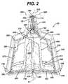
- FIG. 2is a front elevational view of the apparatus of FIG. 1 partially in section.
- FIG. 3is a cross-sectional view of the apparatus of FIG. 1 along line III-III.
- FIG. 4is a front elevational view of the centrifuge bowl and connection sleeve of FIG. 1 , wherein the connection sleeve and outer housing are exploded.
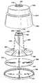
- FIG. 5is an exploded view of the centrifuge bowl of FIG. 1 .
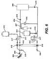
- FIG. 6is a schematic of one embodiment of the apparatus of the present invention, a closed-loop system for ameliorating, preventing, treating, or delaying the onset of diseases.
- FIG. 7is a front-elevational view of an embodiment of a connection sleeve according to the present invention.
- FIG. 8is a cross-sectional view of the connection sleeve of FIG. 7 along line XIII—XIII.
- FIG. 9is a top view of the connection sleeve of FIG. 7 .
- FIG. 10is a bottom view of the connection sleeve of FIG. 7 .
- FIG. 11is a top elevational view the connection sleeve of FIG. 7 having a portion of an external conduit fluidly secured to said connection sleeve.
- FIG. 12is a schematic of an embodiment of the apparatus of FIG. 1 positioned in a 1-omega 2-omega rotational device.
- FIG. 13is a perspective view of a bracket and rotational base of the rotational device of FIG. 12 with a portion of the centrifuge bowl of FIG. 1 positioned therein.
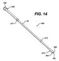
- FIG. 14is a perspective view an embodiment of a conduit assembly according to the present invention.
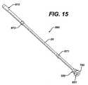
- FIG. 15is an elevated view of the conduit assembly of FIG. 14 from a different perspective.
- FIG. 16is a cross sectional view of the connection sleeve of the conduit assembly of FIG. 15 along line XVII—XVII.
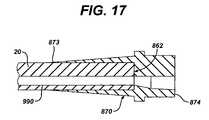
- FIG. 17is a cross sectional view of the anchor sleeve of the conduit assembly of FIG. 14 along line XVIII—XVIII.
- FIG. 18is a perspective view of a second embodiment of a centrifuge bowl according to the present invention.
- FIG. 19is a perspective view of the apparatus of the centrifuge bowl of FIG. 18 partially in section.
- the present inventionrelates to methods and apparatus that separate fluid components, such as, for example, the components of a biological fluid by density or weight.
- Biological fluidsencompass fluids that comprise, exist in, or are used in, or delivered to living organisms.
- biological fluidsmay comprise bodily fluids and their components, such as blood cells, plasma, and other fluids that comprise biological components, including living organisms such as bacteria, cells, or other cellular components.
- Biological fluidsmay also comprise whole blood or specific whole blood components, including red blood cells, platelets, white blood cells, and precursor cells.
- it may be desirable to remove blood from a patient for treatmentsuch as for example, extracorporeal treatment.
- the present inventionis adaptable to use with various centrifugal processing apparatus, and the specific example given herein is merely for illustrative purposes.
- Other uses for the separation techniques and apparatusmay include other medical processes such as dialysis, chemotherapy, platelet separation and removal, and separation and removal of other specific cells.
- the present inventionmay be used to separate other types of fluids that include a wide variety of non-medical uses, such as, for example, oil and fluid component separation.
- All components used in the present inventionshould not adversely affect biological fluids or render them unsuitable for their intended uses, such as those described herein and may be made of any suitable material compatible with uses described herein including, but not limited to plastics, such as polycarbonate, methyl methacrylate, styrene-acrylonitrile, acrylic, styrene, acrylonitrile or any other plastic.
- plasticssuch as polycarbonate, methyl methacrylate, styrene-acrylonitrile, acrylic, styrene, acrylonitrile or any other plastic.
- FIG. 1depicts a specific embodiment of the invention.
- the embodiment of the present invention depicted in FIG. 1comprises a centrifuge bowl 10 in fluid connection with connection sleeve 500 .
- Lower sleeve end 832 ( FIG. 7 ) of connection sleeve 500is secured to bowl 10 .
- Upper sleeve end 831 of connection sleeve 500is secured to external conduit 20 , thus fluidly connecting external conduit 20 to bowl 10 .
- This fluid connectionenables fluid 800 to be supplied through external conduit 20 to bowl 10 .
- this fluid connectionalso enables separated fluid components 810 , 820 to be removed from bowl 10 through external conduit 20 .
- Bowl 10is adapted to be rotated around its center axis 11 .
- Bowl 10comprises outer housing 100 and core 200 .
- outer housing 100is constructed of clear plastic so that core 200 is visible therethrough.
- Outer housing 100comprises housing floor 180 which in turn comprises protrusions 150 for locking bowl 10 into rotational device 900 ( FIG. 12 ).
- Bowl 10is preferably simplified in construction and is easy to manufacture by molding or other known manufacturing processes, such that it may be disposable or used for a limited number of treatments, and is most preferably capable of containing about 125 ml of fluid, such fluid possibly being pressurized.
- the volume capacity of the bowlmay vary depending upon the health of the patient and his or her allowable extracorporeal volume.
- the volume capacity of the bowlmay also vary depending upon the use of the bowl or the particular treatment for which the bowl is utilized.
- the transfer operationsare preferably carried out within a sealed flow system, possibly pressurized, preferably formed of flexible plastic or similar material which can be disposed of after each use.
- outer housing 100is substantially conical-shaped with an upper housing end 110 and a lower housing end 190 .
- Outer housing 100may be made of plastic (such as those plastics listed previously), or any other suitable material.
- Upper housing end 110preferably has a neck 115 .
- Neck 115forms housing outlet 700 ( FIG. 4 ) which is sized to secure and hold sleeve flange 790 of connection sleeve 500 .
- connection sleeve 500can be secured to bowl 10 by any suitable means, including for example, a lip, groove, or tight fit and adhesive with a component of bowl 10 .
- Lower housing end 190has a housing floor 180 of greater diameter than upper end 110 . Housing floor 180 may have an indentation 185 that is used to collect denser fluid 810 .
- the diameter of outer housing 100increases from upper housing end 110 to lower housing end 190 .
- Outer housing 100is adapted to rotatably connect to a rotational device 900 ( FIG. 12 ), such as for example, a rotor drive system or a rotating bracket 910 .
- the rotatable connectionmay, for example, be a bearing that allows free rotation of bowl 10 .
- Outer housing 100preferably has a locking mechanism.
- the locking mechanismmay be one or more protrusions 150 designed to interact with corresponding indentations in a centrifuge container or any other suitable interconnect or locking mechanism or equivalent known in the art.
- the locking mechanismmay also comprise a key slot 160 ( FIG. 18 ).
- outer housing 100has an interior volume 710 in which core 200 will fit when bowl 10 is assembled.
- connection sleeve 500is first mounted to lumen 400 .
- connection sleeve 500extends through housing outlet 700 until sleeve flange 790 engages outer housing 100 near upper housing end 110 .
- core 200is fully within interior volume 710 of outer housing 100 ,occupying a coaxial volume of interior volume 710 about axis 11 .
- bowl 10comprises core 200 positioned inside of outer housing 100 as described above.
- Core 200has an outer wall 210 that is a stacked-conical shape that follows the general shape of outer housing 100 .
- outer wall 210may be a truncated cone-shape that is substantially smooth.
- the interior of core 200is hollow, but may be solid if so desired.
- Interior wall 210 of core 200provides a hollow cylindrical section for lumen 400 to pass through.
- Core 200also comprises upper and lower core ends 205 and 295 , respectively.
- Lower core end 295has a core floor 290 .
- the diameter of core 200preferably increases from upper core end 205 to lower core end 295 .
- Upper core end 205 of core 200has a neck 215 fitted around the outside diameter of multi-axial lumen 400 .
- neck 215 of core 200forms core outlet 720 near upper core end 205 .
- Core outlet 720is sized so that lumen 400 can extend therethrough when assembled.
- core floor 290 and lumen 400are molded so as to be a single structure and having a plurality of fins 250 that provide support for lumen 400 .
- bowl 10can be constructed so that core floor 290 and lumen 400 are separate pieces. In such an embodiment, core floor 290 will have an opening through which lumen 400 will extend therethrough.
- This alternative embodimentmakes it possible for bowl 10 to be adapted so that core 200 , outer housing 100 , and lower plate 300 can rotate about a stationary lumen 400 .
- core 200is positioned inside outer housing 100 , occupying a coaxial volume of interior volume 710 of bowl 10 and forming separation volume 220 between outer wall 210 of core 200 and outer housing 100 .
- Separation volume 220is that space of interior volume 710 that is between core 200 and outer housing 100 .
- Bowl 10further comprises lower plate 300 having top surface 730 .
- Lower plate 300is positioned within separation volume 220 beneath core floor 290 and above housing floor 180 .
- Lower plate 300is circular and curves upward radially from its center (illustrated in FIG. 3 ).
- lower plate 300can be flat.
- spacestill exists both between lower plate 300 and core floor 290 and between lower plate 300 and housing floor 180 . These spaces allow fluid 800 to flow along top surface 730 of lower plate 300 and further allows a first separated fluid component 810 to flow under lower plate 300 atop housing floor 180 .
- Top surface 730 of lower plate 300may also have protrusions, indentations, or other guides that extend from the center of lower plate 300 radially outward to the edge of plate 300 to direct fluid 800 outward.
- Lower plate 300may be made of plastic or any other suitable material.
- Lower plate 300has opening 302 ( FIG. 5 ) near its center through which that portion of lumen 400 that forms second bowl channel 410 extends. Opening 302 can be sized to form a tight fit with this portion of lumen 400 which will hold lower plate 300 suspended above housing floor 180 .
- Multi-axial lumen 400is located inside core 200 .
- Lumen 400has an upper lumen end 480 and a lower lumen end 490 wherein the diameter of lumen 400 increases from upper lumen end 480 to lower lumen end 490 .
- lumen 400comprises first bowl channel 420 , second bowl channel 410 , and third bowl channel 740 .
- First bowl channel 420provides a passageway through lumen 400 to top surface 730 of lower plate 300 for the inflow of fluid 800 .
- Second bowl channel 410is located inside first bowl channel 420 and is completely enclosed therein. Second bowl channel 410 forms a passageway through lumen 400 from below lower plate 300 for the removal of a first separated fluid component 810 that gathers in indentation 185 of housing floor 180 .
- Third bowl channel 740forms a passage way through lumen 400 from separation volume 220 above lower plate 300 for the removal of second separated fluid component 820 .
- third bowl channel 740forms a passageway from that portion of separation volume 220 that is at or near upper housing end 110 .
- third bowl channel 740is L-shaped.
- first, second, and third bowl channels 820 , 810 , 740can be placed at different positions on bowl 10 .
- the bowl channels 820 , 810 , 740may be arranged so as not to be all within lumen 400 , so long as the necessary passageways are formed. For example, alternate configurations such as a single lumen partitioned into equal sections forming multiple lumens and/or fluid passageways will suffice.
- each bowl channel 820 , 810 , 740may be made of any type of flexible or rigid tubing (such as medical tubing) or other such device providing a sealed passageway, possibly for pressurized or unpressurized fluid flow, and which preferably can be disposable and sterilizable, i.e., of simple and efficient manufacture.
- bowl 10is adapted so that outer housing 100 , core 200 , lower plate 300 , and lumen 400 are in connection and rotate together.
- Housing floor 180 of outer housing 100(not illustrated in FIG. 5 ) comprises double ridges 181 on its top surface. Each double ridge 181 comprises two substantially parallel raised protrusions.
- Lower plate 300has single ridges 301 on both its top surface 730 and bottom surface (not illustrated on bottom surface). Each single ridge 301 comprises a single raised linear protrusion. When assembled, each single ridge 301 on the bottom surface of lower plate 300 rests between and engages the two substantially parallel raised protrusions of a corresponding double ridge 181 on housing floor 180 .
- each single ridge 301 on top surface 730 of lower plate 300will engage a corresponding double ridge 301 on the bottom surface of core floor 290 of core 200 .
- core 200 , lower plate 300 , and lumen 400will rotate therewith.
- connection sleeve 500is secured to bowl 10 by means of sleeve flange 790 .
- Connection sleeve 500is also secured to external conduit 20 and is adapted to fluidly connect conduit channels 780 , 760 , 770 of external conduit 20 to bowl channels 420 , 410 , 740 of lumen 400 respectively.
- connection sleeve 500is mounted to lumen 400 .
- connection sleeve 500is adapted to be mounted to lumen connector 481 ( FIGS. 4 and 5 ).
- connection sleeve 500comprises body 830 having an upper sleeve end 831 and lower sleeve end 832 .
- Lower sleeve end 832has sleeve flange 790 which is sized to engage upper housing end 110 when body 830 of connection sleeve 500 is slidably inserted through housing outlet 700 .
- Lower sleeve end 832also comprises lumen mounting recess 851 .
- Lumen mounting recess 851is sized so that lumen connector 481 ( FIG. 4 ) will fit tightly therein.
- Lumen mounting recess 851is triangularly shaped but can take on any shape, so long as it corresponds in shape to that of lumen connector 481 . However it is preferred that lumen mounting recess 851 not be circular. A circular shape would allow connection sleeve 500 to rotate about lumen 400 , causing unwanted friction and possibly producing contaminants.
- upper sleeve end 831is adapted to be secured to external conduit 20 .
- Upper sleeve end 831comprises wall 835 surrounding stub 836 .
- Upper sleeve end 831further comprises trench 837 positioned between wall 835 and stub 836 .
- Trench 837is preferably tapered.
- External conduit 20is secured to connection sleeve 500 (as illustrated in FIG. 11 ) by sliding a raised outer wall portion of external conduit 20 into trench 837 .
- Body 831is sized and shaped so that when sleeve flange 790 engages outer housing 100 , body 831 fits tight in housing outlet 700 , protruding therefrom. This tight fit helps ensure that contagions do not enter bowl 10 .
- stub 836comprises first stub channel 840 , second stub channel 841 , and third stub channel 842 .
- First, second, and third stub channels 840 , 841 , 842extend through stub 836 , each forming a passageway through connection sleeve 500 .
- first stub channel 840fluidly connects first conduit channel 780 with first bowl channel 420 for inflowing fluid 800 from external conduit 20 into bowl 10 for separation.
- second stub channel 841fluidly connects second conduit channel 760 to second bowl channel 410 for removing first separated fluid component 810 from bowl 10 into external conduit 20 .
- third stub channel 842fluidly connects third conduit channel 770 to third bowl channel 740 for removing second separated fluid component 820 from bowl 10 into external conduit 20 .
- Connection sleeve 500connects bowl 10 to external conduit 20 without use of a rotatable seal, which would otherwise normally be located between bowl 10 and connection sleeve 500 .
- the seal-less connection between bowl 10 and connection sleeve 500may occur as explained above or alternatively through use of, for example, an O-ring, a groove, or lip, grommet-type connection, welding, or a tight fit with or without adhesive in either bowl 10 or connection sleeve 500 .
- bowl 10In order for bowl 10 to be used to separate fluid 800 into its higher and lower density components 810 , 820 it is necessary that bowl 10 be rotated in a device capable of spinning bowl 10 at an adequate rotational velocity. However, this spinning must be achieved while still maintaining both the structural integrity of bowl 10 and all of the fluid connections between bowl 10 , connection sleeve 500 , and external conduit 20 .
- rotation of bowl 10 without the use of a rotating sealis achieved through the use of 1-omeg 2-omega spin technology.
- 1-omega/2-omega spin technologyis well known in the art, as seen for example, in U.S. Pat. No. 3,986,442, expressly incorporated by reference herein.
- Rotational devices utilizing 1-omega 2-omega spin technologyallow bowl 10 and external conduit 20 to rotate without the use of a rotatable seal and eliminate any tangling of external conduit 20 .
- a rotational device 900capable of utilizing 1-omega 2-omega spin technology is illustrated with bowl 10 positioned therein.
- Bowl 10is rotatably connected to rotational device 900 , which includes a rotating bracket 910 and an outer frame 914 , both of which are, for example, made of aluminum or some other lightweight, sturdy metal.
- Rotating bracket 910is rotatably connected to bowl 10 and has holders 915 (generically illustrated in FIG. 12 ) that restrain external conduit 20 in a specific configuration that resembles a “truncated reverse-S shape.”
- external conduit 20must maintain a particular configuration, it is still capable of loose rotation within holders 915 .
- external conduit 20is, for example, fed into holders 915 .
- Holders 915may have a wear plate designed to reduce friction and heat generated by friction between external conduit 20 and holder 915 .
- Bracket 910also has an opening through bottom ledge 916 that is designed to rotatably connect bowl 10 to bracket 910 to allow free rotation of bowl 10 .
- This particular configurationallows external conduit 20 to act as a flexible shaft that transmits torque to bowl 10 and provides 2-omega spin.
- Rotating bracket 910rotates while holding external conduit 20 , providing 1-omega revolution, and is preferably driven by a motor 912 or some other energy source known in the art.
- Motor 912has a drive shaft 913 that rotates.
- Drive shaft 913is connected to and transmits torque to bracket shaft 911 through the use of a belt, chain, or other connection (not illustrated).
- Bracket shaft 911in turn transmits rotational energy to bracket 910 and thus to bowl 10 .
- External conduit 20may be lightly restrained by restraint 918 located on outer frame 914 .
- bracket 910Because the rotation and revolution of bracket 910 are in the same direction, this transposition of the bracket 910 results in summation of the rates of rotation and revolution. Consequently, the bracket rotates at half the speed of the bowl (1 ⁇ ) around central axis 11 , hence the term “1-omega.” The bowl 10 rotates at twice the speed (2 ⁇ ) of the bracket, hence the term “2-omega.”
- This rotational systemincludes a drive system for the rotation of bowl 10 .
- bowl 10would be connected to a rotor assembly that is rotatably mounted on a rotor drive assembly that is rotatably mounted to a stationary base.
- Bowl 10 and the rotational device 900may be used in conjunction with a larger system, such as the closed-loop continuous flow system 630 depicted in FIG. 6 .
- a source 600such as a patient for example, is connected to system 630 by a needle or catheter 605 .
- System 630can be any suitable system that can be used to treat, ameliorate, prevent, or delay the onset of T-cell or white blood cell mediated diseases, such as a photopheresis-type unit.
- System 630comprises anticoagulant source 615 , centrifuge bowl 10 within rotational apparatus 900 (not illustrated), buffy coat treatment assembly 609 , a plasma storage chamber (not illustrated), saline source 613 , and drip chamber/filter 614 .
- System 630can be adapted to be a closed-loop system by connecting return needle or catheter 606 to source 600 to reinfuse separated RBCs and treated buffy coat back into the source/patient 600 .
- System 630has a plurality of pumps 617 strategically located to ensure proper pressures and continuous flow throughout system 630 .
- an uninterrupted continuous flow pumpis used, such as the pump described in U.S. patent application Ser. No. 09/389,463, herein incorporated by reference in its entirety.
- System 630further comprises a plurality of flow regulation valves 618 located throughout system 630 to appropriately facilitate and control the flow of fluid through the fluid connections of system 630 .
- the treatment procedurebegins when centrifuge bowl 10 , possibly part of a disposable kit, is placed inside a photopheresis-type unit, or another suitable system, and is locked into rotational device 900 ( FIG. 12 ) via protrusions 150 and/or key slots 160 by a twisting motion.
- bowl 10Once bowl 10 is properly locked into place and fluidly connected to system 630 , blood is drawn from patient 600 and into a sterile tubing set using needle 605 .
- Anticoagulantis then added to the inflowing blood from anticoagulant source 615 in a proportion known in the art to prevent coagulation, such as, for example, disclosed in U.S. patent application Ser. No. 09/480,893, herein expressly incorporated by reference.
- the incoming whole blood, with a percentage of anticoagulantthen enters bowl 10 .
- this incoming whole blood 800enters rotating centrifuge bowl 10 by passing into first conduit channel 780 of external conduit 20 , through first stub channel 840 ( FIG. 9 ) of connection sleeve 500 , and into first bowl channel 420 of bowl 10 .
- Whole blood 800flows downward through first bowl channel 420 until it reaches top surface 730 of lower plate 300 in separation volume 220 .
- centrifugal forcesseparate the whole blood 800 into a first separated fluid component 810 and second separated fluid component 820 .
- Separated fluid components 810 , 820are separated into different fractions in accordance with the component densities.
- the higher density fluid component 810comprises red blood cells (“RBCs”) while the lower density component 820 comprises buffy coat (WBCs, platelets, and plasma).
- RBCsred blood cells
- WBCsbuffy coat
- the higher density componentwhich in the present embodiment is RBCs 810 , falls to the bottom of bowl 10 and onto housing floor 180 of outer housing 100 .
- the RBCs 810flow downward, due to their heavier weight, they flow in an opposite direction of the buffy coat 810 , which may flow, for example, upwards.
- RBCs 810As RBCs 810 aggregate in the bottom of bowl 10 , some RBCs 810 will eventually be pushed into and gather in indentation 185 in the center of housing floor 180 in that part of separation volume 220 below lower plate 300 . Once gathered in indentation 185 below lower plate 300 , the RBCs 810 are removed from bowl 10 by the RBCs 810 flowing upward through second bowl channel 410 , through second stub channel 841 of connection sleeve 500 , and into second conduit channel 760 of external conduit 760 .
- buffy coat 820begins to aggregate and rise through separation volume 220 because it is less dense.
- the buffy coat 820rises in bowl 10 , forcing buffy coat 820 towards the top of separation volume 220 .
- the buffy coat 820enters third bowl channel 740 , flowing upward out of bowl 10 via third bowl channel 740 , through third stub channel 842 ( FIG. 9 ) of connection sleeve 500 , and into third conduit channel 770 of external conduit 20 .
- RBCs 810may be removed from bowl 10 via a pumping means.
- buffy coat 820may be prevented from exiting bowl 10 by any means known in the art, thus, for example, increasing the overall pressure in the bowl, forcing the RBCs 810 out of the bowl.
- Bowl 10via external conduit 20 , may be continuously emptied of its contents (RBCs 810 and buffy coat 820 ) to prevent a pause in a treatment cycle, or a “batch-type” process. Because bowl 10 provides a more continuous separation system, the effective separation of the components should increase with respect to time.
- the apparatus and methods of the present inventionmay also, for example, be used to remove platelets from blood in much the same way, with the exception that the platelets may be removed instead of buffy coat.
- a surge-type techniquemay be used. In this technique, plasma may be flushed into the bowl to float platelets to the top of the separation volume for their removal.
- the centrifuge apparatus and associated systems and methodsmay be automated by sensors, controllers, and other means of automation known in the art.
- RBCs 810 and buffy coat 820are preferably pumped or pushed out of bowl 10 and then continue to be used in a photopheresis treatment system, such as system 630 .
- buffy coat treatment assembly 609(generically illustrated) where it is properly processed for reinfusion back into source 600 for treatment or amelioration of the aforementioned conditions or diseases.
- Buffy coat treatment assembly 609will comprise the equipment necessary to process the buffy coat 820 as necessary for proper patient treatment, such as a chamber for holding buffy coat 810 and a source of ultra-violet radiation adapted to expose the buffy coat 820 to UV radiation. The exact equipment and design of buffy coat treatment assembly 609 will depend on the exact treatment requirements of the patient as known to those skilled in the art. After being processed in treatment assembly 609 , the buffy coat exits treatment assembly 609 for reinfusion into source/patient 600 .
- the RBCs 810Upon leaving bowl 10 , the RBCs 810 flow into tubing 607 to be directly reinfused into source/patient 600 . Before reinfusing RBC's 810 and/or buffy coat 820 into patient 600 via needle or catheter 606 , these fluids are flowed through drip chamber/filter 614 . Saline can also be added to the fluids from saline source 613 . When needle/catheter 606 is connected to patient 600 , a closed-loop system is formed that can be used to continuously treat patient 600 without the need to batch-process blood 800 .
- needles/catheters 605 and 606are illustrated as single lumen needles/catheters, it is possible to use a double lumen catheter in system 630 so that the same needle/catheter can be used to both remove and reinfuse fluids from the patient.
- a “cleaner cut”means that the hermatocrit count (HCT %) is decreased.
- HCT %is the amount of red blood cells present per volume of buffy coat.
- the amount of time that buffy coat 820 is subjected to rotational motion in centrifuge bowl 10can be maximized in the following manner. First, whole blood 800 is fed into first bowl channel 420 as centrifuge bowl 10 is rotating. As discussed above, whole blood 800 is separated into buffy coat 820 and RBC's 810 as it moves outwardly atop lower plate 300 .
- Second bowl channel 410 and third bowl channel 740are closed at this time.
- the inflow of whole blood 800is continued until the separation volume 220 is filled with a combination of buffy coat 820 near the top and RBC's 810 near the bottom of centrifuge bowl 10 .
- second bowl channel 410By removing RBC's 810 from centrifuge bowl 10 via second bowl channel 410 only, additional volume is created for the inflow of whole blood 800 and the unremoved buffy coat 820 is subjected to rotational forces for an extended period of time.
- centrifuge bowl 10continues to rotate, some of the RBC's 810 that may be trapped in buffy coat 820 get pulled to the bottom of centrifuge bowl 10 and away from third bowl channel 740 and buffy coat 820 .
- the buffy coat 820 that is removedhas a lower HCT %.
- 90–100 milliliters of buffy coat/white blood cellsmust be captured in order to conduct a full photophoresis treatment.
- the present inventionneeds to process around 1.5 liters of whole blood.
- the required amount of buffy coat/white blood cellscan be removed from the 1.5 liters of whole blood in about 30–45 minutes using the present invention, collecting around 60% or more of the total amount of the buffy coat/white blood cells that are subjected to the separation process.
- the captured buffy coat/white blood cellshave an HCT of 2% or less.
- the UVAR XTStakes around 90 minutes to process 1.5 liters of whole blood to obtain the sufficient amount of buffy coat/white blood cells.
- the UVAR XTSonly collects around 50% of the total amount of the buffy coat/white blood cells that are subjected to the separation process.
- the HCT of the buffy coat/white blood cells collected by the UVAR XTSis around, but not substantially below, 2%.
- Another existing apparatus, the Cobe SpectraTM by Gambromust process 10 liters of whole blood in order to collect the sufficient amount of buffy coat/white blood cells. This typically takes around 150 minutes, collecting only 10–15% of the total amount of the buffy coat/white blood cells that are subjected to the separation process, and having an HCT of about 2%.
- the present inventioncan perform the same functions in less than 70 minutes. These times do not include the patient preparation or prime time. The times indicate only the total time that the patient is connected to the system 630 .
- bowl 10must be secured within rotational device 900 and allowed to rotate therein while remaining fluidly connected to system 630 ( FIG. 6 ).
- system 630FIG. 6
- the use of a rotatable sealis undesirable.
- the cyclical rotation of bowl 10 and external conduit 20can cause the fluid connection to fail in a variety of ways, including structural failure.
- conduit assembly 860FIG. 14 is utilized.
- Conduit assembly 860comprises external conduit 20 , connection sleeve 500 , anchor sleeve 870 , and first and second bearing rings 871 , 872 .
- Connection sleeve 100is adapted to be secured to bowl 10 when bowl 10 is in rotational device 900 .
- Anchor sleeve 870is connected in a stationary position to restraint 918 of rotational device 900 ( FIG. 12 ) and fluidly connects external conduit 20 to the rest of system 630 .
- Conduit assembly 860further comprises first, second, and third assembly channels 990 , 991 , and 992 that extend through conduit assembly 860 and through which fluids can flow.
- External conduit 20has an approximately constant diameter. Constructing external conduit 20 to have a constant diameter helps reduce the problem of the external conduit being too rigid. An excessively rigid external conduit will heat up and fail more quickly. Additionally, a constant diameter conduit is cheap/easy to manufacture, allows easy experimentation with connection sleeve 500 and anchor sleeve 870 sizes, and allows bearing rings 871 , 872 to be easily slid thereon. External conduit 20 may be made of any type of flexible tubing (such as medical tubing) or other such device providing a sealed passageway for the flow of fluids, which may be pressurized, into or out of a reservoir of any sort, and which preferably can be disposable and sterilizable.
- First and second bearing rings 871 , 872surround external conduit 20 and allow free rotation of external conduit 20 therein.
- external conduit 20is supported by bracket 910 through the use of holders 915 which are generically illustrated in FIG. 12 .
- holders 15can be roller assemblies adapted to engage ring bearings 871 and 872 so as to allow rotation of external conduit 20 therein.
- the positioning of ring bearings 871 and 872 on external conduit 20is critical to the cyclical duration of the external conduit 20 . For a centrifuge bowl having a height of 5 inches and a width of 5 inches, an external conduit having a length of approximately 21 inches is used.
- first bearing ring 871 and second bearing 872between 7.5 to 9.5 inches apart will increase the survival time of external conduit 20 .
- first bearing ring 871 and second bearing 872will be approximately 8.5 inches apart.
- first bearing ring 871be between 5.0 to 5.5 inches away from first end 832 of connection sleeve 500 ( FIG. 16 ). These distances are exemplary only. Optimal distance/spacing measurements are dependent on the length of the external conduit, the size of the centrifuge bowl, and the spacing between and number of holder 15 used.
- connection sleeve 500has upper sleeve end 831 and lower sleeve end 832 .
- Lower sleeve end 832comprises sleeve flange 790 which can be used to secure connection sleeve 500 to centrifuge bowl 10 , as described above.
- Lower sleeve end 832also comprises lumen mounting recess 851 ( FIG. 15 ).
- Lumen mounting recess 851is adapted and sized to mount to a lumen 400 of a centrifuge bowl 10 as described above.
- Connection sleeve 500preferably increases in diameter from upper sleeve end 831 to lower sleeve end 832 and is overmolded to first conduit end 861 of external conduit 20 . The remaining characteristics of connection sleeve 500 of conduit assembly 860 are described above.
- anchor sleeve 870has first anchor end 873 and second anchor end 874 .
- Anchor sleeve 870is overmolded to second conduit end 862 of external conduit 20 and increases in diameter from first anchor end 873 to second anchor end 874 .
- FIGS. 18 and 19illustrate a second embodiment of bowl 10 .
- the locking mechanism for securing the second embodiment of bowl 10 to rotational device 900comprises both protrusions 150 and key slots 160 .
- core floor 290 of core 200extends past outer wall 210 into separation volume 220 and provides, for example, a curved floor flange 280 .
- the curve of floor flange 280may helps to move the buffy coat upward, possibly acting as a barrier to the buffy coat, thereby preventing the buffy coat from being dragged by the RBCs.
- lower plate 300may comprise hollow cylinder 320 .
- hollow cylinder 320may be more than one cylinder stacked on top of each other having various diameters and heights.
- Hollow cylinder 320has an outer diameter substantially less than lower plate 300 and is adapted to surround lumen 400 by tight fit and holds lower plate 300 suspended above housing floor 180 .
- Second channel 410extends from housing floor 180 of outer housing 100 through hollow cylinder 320 to connection sleeve 500 .
- Hollow cylinder 320provides a tight fit around inner lumen 410 , providing support for lumen 400 at its lower end.
Landscapes
- Health & Medical Sciences (AREA)
- Heart & Thoracic Surgery (AREA)
- Vascular Medicine (AREA)
- Life Sciences & Earth Sciences (AREA)
- Engineering & Computer Science (AREA)
- Anesthesiology (AREA)
- Biomedical Technology (AREA)
- Hematology (AREA)
- Cardiology (AREA)
- Animal Behavior & Ethology (AREA)
- General Health & Medical Sciences (AREA)
- Public Health (AREA)
- Veterinary Medicine (AREA)
- External Artificial Organs (AREA)
- Centrifugal Separators (AREA)
- Medicines Containing Material From Animals Or Micro-Organisms (AREA)
Abstract
Description
Claims (6)
Priority Applications (20)
| Application Number | Priority Date | Filing Date | Title |
|---|---|---|---|
| US10/375,629US7186230B2 (en) | 2002-03-04 | 2003-02-27 | Method and apparatus for the continuous separation of biological fluids into components |
| BRPI0308164-8ABR0308164B1 (en) | 2002-03-04 | 2003-02-28 | apparatus and method for separating components of a fluid. |
| EP03716220.3AEP1483000B1 (en) | 2002-03-04 | 2003-02-28 | Method and apparatus for the continuous fractionation of biological fluids |
| JP2003574251AJP4519467B2 (en) | 2002-03-04 | 2003-02-28 | Improved method and apparatus for the continuous separation of biological fluids into components |
| CA2478187ACA2478187C (en) | 2002-03-04 | 2003-02-28 | Method and apparatus for the continuous fractionation of biological fluids into components |
| AU2003219935AAU2003219935B2 (en) | 2002-03-04 | 2003-02-28 | Method and apparatus for the continuous fractionation of biological fluids |
| ES03716220.3TES2483169T3 (en) | 2002-03-04 | 2003-02-28 | Procedure and apparatus for the continuous fractionation of biological fluids |
| NZ552287ANZ552287A (en) | 2002-03-04 | 2003-02-28 | Method and apparatus for the continuous fractionation of bilogical fluids |
| NZ544491ANZ544491A (en) | 2002-03-04 | 2003-02-28 | Method and apparatus for the continuous fractionation of biological fluids |
| NZ534867ANZ534867A (en) | 2002-03-04 | 2003-02-28 | Method and apparatus for the continuous fractionation of biological fluids |
| PCT/US2003/006032WO2003075983A2 (en) | 2002-03-04 | 2003-02-28 | Method and apparatus for the continuous fractionation of biological fluids |
| MXPA04008548AMXPA04008548A (en) | 2002-03-04 | 2003-02-28 | Method and apparatus for the continuous fractionation of biological fluids. |
| US10/654,794US20040127840A1 (en) | 2002-03-04 | 2003-09-03 | Blood separation apparatus and method of using the same |
| US10/654,803US7479123B2 (en) | 2002-03-04 | 2003-09-03 | Method for collecting a desired blood component and performing a photopheresis treatment |
| US10/654,742US7211037B2 (en) | 2002-03-04 | 2003-09-03 | Apparatus for the continuous separation of biological fluids into components and method of using same |
| US11/406,988US7914477B2 (en) | 2002-03-04 | 2006-04-19 | Apparatus for the continuous separation of biological fluids into components and method of using same |
| US11/407,271US7503889B2 (en) | 2002-03-04 | 2006-04-19 | Apparatus for the continuous separation of biological fluids into components and method of using same |
| US11/613,021US7850634B2 (en) | 2002-03-04 | 2006-12-19 | Method for collecting a desired blood component and performing a photopheresis treatment |
| US12/795,308US9238097B2 (en) | 2002-03-04 | 2010-06-07 | Method for collecting a desired blood component and performing a photopheresis treatment |
| US15/491,835US10556055B2 (en) | 2002-03-04 | 2017-04-19 | Method for collecting a desired blood component and performing a photopheresis treatment |
Applications Claiming Priority (2)
| Application Number | Priority Date | Filing Date | Title |
|---|---|---|---|
| US36128702P | 2002-03-04 | 2002-03-04 | |
| US10/375,629US7186230B2 (en) | 2002-03-04 | 2003-02-27 | Method and apparatus for the continuous separation of biological fluids into components |
Related Child Applications (3)
| Application Number | Title | Priority Date | Filing Date |
|---|---|---|---|
| US10/654,803Continuation-In-PartUS7479123B2 (en) | 2002-03-04 | 2003-09-03 | Method for collecting a desired blood component and performing a photopheresis treatment |
| US10/654,742Continuation-In-PartUS7211037B2 (en) | 2002-03-04 | 2003-09-03 | Apparatus for the continuous separation of biological fluids into components and method of using same |
| US11/613,021Continuation-In-PartUS7850634B2 (en) | 2002-03-04 | 2006-12-19 | Method for collecting a desired blood component and performing a photopheresis treatment |
Publications (2)
| Publication Number | Publication Date |
|---|---|
| US20030181305A1 US20030181305A1 (en) | 2003-09-25 |
| US7186230B2true US7186230B2 (en) | 2007-03-06 |
Family
ID=28045234
Family Applications (1)
| Application Number | Title | Priority Date | Filing Date |
|---|---|---|---|
| US10/375,629Expired - LifetimeUS7186230B2 (en) | 2002-03-04 | 2003-02-27 | Method and apparatus for the continuous separation of biological fluids into components |
Country Status (10)
| Country | Link |
|---|---|
| US (1) | US7186230B2 (en) |
| EP (1) | EP1483000B1 (en) |
| JP (1) | JP4519467B2 (en) |
| AU (1) | AU2003219935B2 (en) |
| BR (1) | BR0308164B1 (en) |
| CA (1) | CA2478187C (en) |
| ES (1) | ES2483169T3 (en) |
| MX (1) | MXPA04008548A (en) |
| NZ (3) | NZ544491A (en) |
| WO (1) | WO2003075983A2 (en) |
Cited By (15)
| Publication number | Priority date | Publication date | Assignee | Title |
|---|---|---|---|---|
| US20060199720A1 (en)* | 2005-01-21 | 2006-09-07 | Tien-Chu Juan | Plasmapheresis centrifuge bowl |
| US20080153686A1 (en)* | 2005-01-25 | 2008-06-26 | Jean-Denis Rochat | Disposable Device for the Continuous Centrifugal Separation of a Physiological Fluid |
| US20100049134A1 (en)* | 2008-08-21 | 2010-02-25 | Schuman Jr Peter J | Pump device, tube device and method for movement and collection of fluid |
| WO2010075061A2 (en) | 2008-12-23 | 2010-07-01 | Johnson & Johnson Research Pty Limited | Processing blood |
| USD624180S1 (en)* | 2008-08-27 | 2010-09-21 | Deka Products Limited Partnership | Connector for fluid supply for a patient infusion |
| US9238097B2 (en) | 2002-03-04 | 2016-01-19 | Therakos, Inc. | Method for collecting a desired blood component and performing a photopheresis treatment |
| USD809909S1 (en) | 2013-03-15 | 2018-02-13 | Cook Medical Technologies Llc | Tubing clips |
| US10683478B1 (en)* | 2019-05-16 | 2020-06-16 | Shenzhen Eureka biotechnology Co. Ltd | Device and system for processing a liquid sample containing cells |
| US11311823B2 (en) | 2019-03-05 | 2022-04-26 | Fenwal, Inc. | Collection of mononuclear cells and peripheral blood stem cells |
| US11465160B2 (en) | 2016-09-16 | 2022-10-11 | Fenwal, Inc. | Blood separation systems and methods employing centrifugal and spinning membrane separation techniques |
| US11484891B2 (en) | 2019-05-23 | 2022-11-01 | Fenwal, Inc. | Adjustment of target interface location between separated fluid components in a centrifuge |
| US11890399B2 (en) | 2019-05-23 | 2024-02-06 | Fenwal, Inc. | Centrifugal separation and collection of red blood cells, plasma, or both red blood cells and plasma |
| US11957828B2 (en) | 2019-09-16 | 2024-04-16 | Fenwal, Inc. | Dynamic adjustment of algorithms for separation and collection of blood components |
| US11969536B2 (en) | 2019-12-12 | 2024-04-30 | Fenwal, Inc. | Systems enabling alternative approaches to therapeutic red blood cell exchange and/or therapeutic plasma exchange |
| US12168087B2 (en) | 2019-03-05 | 2024-12-17 | Fenwal, Inc. | Collection, genome editing, and washing of T-cell lymphocytes |
Families Citing this family (22)
| Publication number | Priority date | Publication date | Assignee | Title |
|---|---|---|---|---|
| US6524231B1 (en) | 1999-09-03 | 2003-02-25 | Baxter International Inc. | Blood separation chamber with constricted interior channel and recessed passage |
| ITMI20010899A1 (en)* | 2001-04-30 | 2002-10-30 | Dideco Spa | CELL WASHING PHASE CONTROL SYSTEM FOR BLOOD CENTRIFUGATION |
| US7211037B2 (en)* | 2002-03-04 | 2007-05-01 | Therakos, Inc. | Apparatus for the continuous separation of biological fluids into components and method of using same |
| US7297272B2 (en) | 2002-10-24 | 2007-11-20 | Fenwal, Inc. | Separation apparatus and method |
| US8506825B2 (en) | 2006-11-27 | 2013-08-13 | Sorin Group Italia S.R.L. | Method and apparatus for controlling the flow rate of washing solution during the washing step in a blood centrifugation bowl |
| US20080200859A1 (en)* | 2007-02-15 | 2008-08-21 | Mehdi Hatamian | Apheresis systems & methods |
| US8685258B2 (en) | 2008-02-27 | 2014-04-01 | Fenwal, Inc. | Systems and methods for conveying multiple blood components to a recipient |
| US8075468B2 (en) | 2008-02-27 | 2011-12-13 | Fenwal, Inc. | Systems and methods for mid-processing calculation of blood composition |
| EP2138237B1 (en) | 2008-06-10 | 2011-01-19 | Sorin Group Italia S.r.l. | A securing mechanism, particularly for blood separation centrifuges and the like |
| US8469871B2 (en)* | 2010-11-19 | 2013-06-25 | Kensey Nash Corporation | Centrifuge |
| WO2012137086A1 (en) | 2011-04-08 | 2012-10-11 | Sorin Group Italia S.R.L. | Disposable device for centrifugal blood separation |
| US11878311B2 (en)* | 2011-11-21 | 2024-01-23 | Pneumatic Scale Corporation | Centrifuge system for separating cells in suspension |
| US12350686B2 (en)* | 2011-11-21 | 2025-07-08 | Pneumatic Scale Corporation | Centrifuge system for separating cells in suspension |
| EP2914381B1 (en)* | 2012-11-05 | 2019-07-10 | Haemonetics Corporation | Continuous flow separation chamber |
| US10039876B2 (en) | 2014-04-30 | 2018-08-07 | Sorin Group Italia S.R.L. | System for removing undesirable elements from blood using a first wash step and a second wash step |
| CN106267426A (en)* | 2016-08-15 | 2017-01-04 | 董稳 | A kind of centrifugal separation sampled plasma device |
| US11065376B2 (en) | 2018-03-26 | 2021-07-20 | Haemonetics Corporation | Plasmapheresis centrifuge bowl |
| US11957998B2 (en)* | 2019-06-06 | 2024-04-16 | Pneumatic Scale Corporation | Centrifuge system for separating cells in suspension |
| CN110801649B (en)* | 2019-11-14 | 2021-08-24 | 安徽理工大学 | A laboratory-used ore pulp centrifugal concentration and separation device |
| WO2022240568A1 (en)* | 2021-05-11 | 2022-11-17 | Kaloud, Inc. | Assembly and device for a sealed interim chamber within a hookah |
| US20230285654A1 (en)* | 2022-03-10 | 2023-09-14 | Terumo Bct, Inc. | Blood component collection bladder |
| CN115125102A (en)* | 2022-08-25 | 2022-09-30 | 深圳赛桥生物创新技术有限公司 | Cell separation device and method |
Citations (87)
| Publication number | Priority date | Publication date | Assignee | Title |
|---|---|---|---|---|
| US3145713A (en) | 1963-09-12 | 1964-08-25 | Protein Foundation Inc | Method and apparatus for processing blood |
| US3986442A (en) | 1975-10-09 | 1976-10-19 | Baxter Laboratories, Inc. | Drive system for a centrifugal liquid processing system |
| US4059108A (en) | 1974-08-15 | 1977-11-22 | Haemonetics Corporation | Process for pheresis procedure and disposable pheresis bowl therefor |
| US4086924A (en) | 1976-10-06 | 1978-05-02 | Haemonetics Corporation | Plasmapheresis apparatus |
| US4108353A (en) | 1977-08-31 | 1978-08-22 | Baxter Travenol Laboratories, Inc. | Centrifugal apparatus with oppositely positioned rotational support means |
| US4109855A (en) | 1977-10-25 | 1978-08-29 | Baxter Travenol Laboratories, Inc. | Drive system for centrifugal processing apparatus |
| US4109852A (en) | 1977-10-21 | 1978-08-29 | Baxter Travenol Laboratories, Inc. | Centrifugal strain relief sheath for processing apparatus |
| US4109854A (en) | 1977-06-13 | 1978-08-29 | Baxter Travenol Laboratories, Inc. | Centrifugal apparatus with outer enclosure |
| US4111356A (en) | 1977-07-13 | 1978-09-05 | Baxter Travenol Laboratories, Inc. | Centrifugal apparatus with flexible sheath |
| US4114802A (en) | 1977-08-29 | 1978-09-19 | Baxter Travenol Laboratories, Inc. | Centrifugal apparatus with biaxial connector |
| US4120449A (en) | 1977-06-13 | 1978-10-17 | Baxter Travenol Laboratories, Inc. | Centrifugal processing apparatus using tube drive |
| US4201525A (en) | 1978-07-05 | 1980-05-06 | Baxter Travenol Laboratories, Inc. | Peristaltic pump |
| US4204537A (en) | 1974-08-15 | 1980-05-27 | Haemonetics Corporation | Process for pheresis procedure and disposable plasma |
| US4285464A (en) | 1979-01-22 | 1981-08-25 | Haemonetics Corporation | Apparatus for separation of blood into components thereof |
| US4300717A (en) | 1979-04-02 | 1981-11-17 | Haemonetics Corporation | Rotary centrifuge seal |
| US4303193A (en) | 1979-01-22 | 1981-12-01 | Haemonetics Corporation | Apparatus for separating blood into components thereof |
| US4305659A (en) | 1980-03-06 | 1981-12-15 | Baxter Travenol Laboratories, Inc. | Photometric apparatus and method |
| US4309993A (en) | 1980-03-06 | 1982-01-12 | Baxter Travenol Laboratories, Inc. | Liquid flow sensing apparatus |
| US4321919A (en) | 1979-12-11 | 1982-03-30 | Leukocyte Research, Inc. | Method and system for externally treating human blood |
| US4333016A (en) | 1980-03-06 | 1982-06-01 | Baxter Travenol Laboratories, Inc. | Liquid presence detector |
| US4374731A (en) | 1980-03-06 | 1983-02-22 | Baxter Travenol Laboratories, Inc. | Method and apparatus for obtaining a desired rate of plasma collection from a membrane plasmapheresis filter |
| US4389206A (en) | 1980-10-09 | 1983-06-21 | Baxter Travenol Laboratories, Inc. | Centrifugal processing apparatus and rotatable processing bowl apparatus |
| US4398906A (en) | 1979-12-11 | 1983-08-16 | Frederic A. Bourke, Jr. | Method for externally treating the blood |
| US4417884A (en) | 1981-07-09 | 1983-11-29 | Haemonetics Corporation | Centrifuge timer clamp |
| US4421503A (en) | 1981-07-09 | 1983-12-20 | Haemonetics Corporation | Fluid processing centrifuge and apparatus thereof |
| US4425116A (en) | 1980-04-14 | 1984-01-10 | Baxter Travenol Laboratories, Inc. | Control system for fluid flow apparatus |
| US4428744A (en)* | 1979-12-11 | 1984-01-31 | Frederic A. Bourke, Jr. | Method and system for externally treating the blood |
| US4464166A (en) | 1981-06-12 | 1984-08-07 | Frederic A. Bourke, Jr. | Method for externally treating the blood |
| US4479761A (en) | 1982-12-28 | 1984-10-30 | Baxter Travenol Laboratories, Inc. | Actuator apparatus for a prepackaged fluid processing module having pump and valve elements operable in response to externally applied pressures |
| US4479760A (en) | 1982-12-28 | 1984-10-30 | Baxter Travenol Laboratories, Inc. | Actuator apparatus for a prepackaged fluid processing module having pump and valve elements operable in response to applied pressures |
| US4479762A (en) | 1982-12-28 | 1984-10-30 | Baxter Travenol Laboratories, Inc. | Prepackaged fluid processing module having pump and valve elements operable in response to applied pressures |
| US4530691A (en) | 1983-12-13 | 1985-07-23 | Baxter Travenol Laboratories, Inc. | Centrifuge with movable mandrel |
| US4605503A (en) | 1983-05-26 | 1986-08-12 | Baxter Travenol Laboratories, Inc. | Single needle blood fractionation system having adjustable recirculation through filter |
| US4680025A (en) | 1982-08-24 | 1987-07-14 | Baxter Travenol Laboratories, Inc. | Blood component collection systems and methods |
| US4724317A (en) | 1985-12-05 | 1988-02-09 | Baxter Travenol Laboratories, Inc. | Optical data collection apparatus and method used with moving members |
| US4806252A (en) | 1987-01-30 | 1989-02-21 | Baxter International Inc. | Plasma collection set and method |
| US4834890A (en) | 1987-01-30 | 1989-05-30 | Baxter International Inc. | Centrifugation pheresis system |
| DE3817664A1 (en) | 1988-05-25 | 1989-11-30 | Josef Dr Theissen | Method and device for lavage of blood cells |
| US4940543A (en) | 1987-01-30 | 1990-07-10 | Baxter International Inc. | Plasma collection set |
| US5076911A (en) | 1987-01-30 | 1991-12-31 | Baxter International Inc. | Centrifugation chamber having an interface detection surface |
| EP0297216B1 (en)* | 1987-04-08 | 1992-03-18 | DIDECO S.p.A. | Centrifugation bowl for the continuous centrifugation of blood |
| US5104526A (en) | 1987-01-30 | 1992-04-14 | Baxter International Inc. | Centrifugation system having an interface detection system |
| US5240614A (en) | 1992-01-10 | 1993-08-31 | Baxter International Inc. | Process for removing unwanted materials from fluids and for producing biological products |
| US5316667A (en) | 1989-05-26 | 1994-05-31 | Baxter International Inc. | Time based interface detection systems for blood processing apparatus |
| US5360542A (en) | 1991-12-23 | 1994-11-01 | Baxter International Inc. | Centrifuge with separable bowl and spool elements providing access to the separation chamber |
| US5370802A (en) | 1987-01-30 | 1994-12-06 | Baxter International Inc. | Enhanced yield platelet collection systems and methods |
| US5427509A (en) | 1993-12-22 | 1995-06-27 | Baxter International Inc. | Peristaltic pump tube cassette with angle pump tube connectors |
| US5427695A (en) | 1993-07-26 | 1995-06-27 | Baxter International Inc. | Systems and methods for on line collecting and resuspending cellular-rich blood products like platelet concentrate |
| US5462416A (en) | 1993-12-22 | 1995-10-31 | Baxter International Inc. | Peristaltic pump tube cassette for blood processing systems |
| US5494592A (en) | 1993-04-27 | 1996-02-27 | Haemonetics Corporation | Apheresis apparatus and method |
| US5514069A (en) | 1993-12-22 | 1996-05-07 | Baxter International Inc. | Stress-bearing umbilicus for a compact centrifuge |
| US5525218A (en) | 1993-10-29 | 1996-06-11 | Baxter International Inc. | Centrifuge with separable bowl and spool elements providing access to the separation chamber |
| US5527467A (en) | 1992-01-10 | 1996-06-18 | Baxter International Inc. | Rectifying dialyzer, bioreactor and membrane |
| US5538405A (en) | 1994-07-01 | 1996-07-23 | Baxter International Inc. | Peristaltic pulse pumping systems and methods |
| US5549834A (en) | 1991-12-23 | 1996-08-27 | Baxter International Inc. | Systems and methods for reducing the number of leukocytes in cellular products like platelets harvested for therapeutic purposes |
| US5551942A (en) | 1993-12-22 | 1996-09-03 | Baxter International Inc. | Centrifuge with pivot-out, easy-load processing chamber |
| US5573678A (en) | 1987-01-30 | 1996-11-12 | Baxter International Inc. | Blood processing systems and methods for collecting mono nuclear cells |
| US5628915A (en) | 1987-01-30 | 1997-05-13 | Baxter International Inc. | Enhanced yield blood processing systems and methods establishing controlled vortex flow conditions |
| US5632893A (en) | 1987-01-30 | 1997-05-27 | Baxter Internatinoal Inc. | Enhanced yield blood processing systems with angled interface control surface |
| US5639382A (en) | 1991-12-23 | 1997-06-17 | Baxter International Inc. | Systems and methods for deriving recommended storage parameters for collected blood components |
| US5641414A (en) | 1987-01-30 | 1997-06-24 | Baxter International Inc. | Blood processing systems and methods which restrict in flow of whole blood to increase platelet yields |
| EP0786324A1 (en) | 1996-01-24 | 1997-07-30 | B. Braun Melsungen Ag | Method of connecting a medical tube to a plastic adapter |
| US5656163A (en) | 1987-01-30 | 1997-08-12 | Baxter International Inc. | Chamber for use in a rotating field to separate blood components |
| WO1997036634A1 (en) | 1996-03-29 | 1997-10-09 | Therakos, Inc. | Photopheresis treatment of chronic hcv infections |
| WO1997036581A1 (en)* | 1996-03-29 | 1997-10-09 | Therakos, Inc. | Photopheresis treatment of leukocytes |
| US5676841A (en) | 1991-12-23 | 1997-10-14 | Baxter International Inc. | Blood processing systems and methods which monitor citrate return to the donor |
| US5681273A (en) | 1991-12-23 | 1997-10-28 | Baxter International Inc. | Systems and methods for predicting blood processing parameters |
| US5690835A (en) | 1991-12-23 | 1997-11-25 | Baxter International Inc. | Systems and methods for on line collection of cellular blood components that assure donor comfort |
| US5730883A (en) | 1991-12-23 | 1998-03-24 | Baxter International Inc. | Blood processing systems and methods using apparent hematocrit as a process control parameter |
| US5759413A (en) | 1995-06-07 | 1998-06-02 | Baxter International Inc. | Systems and method for estimating platelet counts using a spleen mobilization function |
| US5792372A (en) | 1987-01-30 | 1998-08-11 | Baxter International, Inc. | Enhanced yield collection systems and methods for obtaining concentrated platelets from platelet-rich plasma |
| US5833866A (en) | 1991-12-23 | 1998-11-10 | Baxter International Inc. | Blood collection systems and methods which derive instantaneous blood component yield information during blood processing |
| US5945291A (en) | 1997-11-10 | 1999-08-31 | Coulter International Corp. | Method for distinguishing viable, early apoptotic, late apoptotic, and necrotic cells |
| US5958250A (en) | 1995-06-07 | 1999-09-28 | Baxter International Inc. | Blood processing systems and methods which optically derive the volume of platelets contained in a plasma constituent |
| US5961842A (en) | 1995-06-07 | 1999-10-05 | Baxter International Inc. | Systems and methods for collecting mononuclear cells employing control of packed red blood cell hematocrit |
| US5980757A (en) | 1997-04-03 | 1999-11-09 | Baxter International Inc. | Interface detection and control systems and method |
| US5980760A (en) | 1997-07-01 | 1999-11-09 | Baxter International Inc. | System and methods for harvesting mononuclear cells by recirculation of packed red blood cells |
| US6007725A (en) | 1991-12-23 | 1999-12-28 | Baxter International Inc. | Systems and methods for on line collection of cellular blood components that assure donor comfort |
| US6027657A (en) | 1997-07-01 | 2000-02-22 | Baxter International Inc. | Systems and methods for collecting diluted mononuclear cells |
| EP1066842A2 (en) | 1999-07-09 | 2001-01-10 | Therakos, Inc. | Method and system for determining an effective amount of energy to deliver to fluids in phototherapy |
| US6204058B1 (en) | 1992-02-07 | 2001-03-20 | Vasogen Ireland Limited | Treatment of autoimmune diseases |
| US6261065B1 (en) | 1999-09-03 | 2001-07-17 | Baxter International Inc. | System and methods for control of pumps employing electrical field sensing |
| US6296450B1 (en) | 1999-09-03 | 2001-10-02 | Baxter International Inc. | Systems and methods for control of pumps employing gravimetric sensing |
| US6312607B1 (en) | 1995-06-07 | 2001-11-06 | Baxter International Inc. | Blood processing systems and methods which optically monitor incremental platelet volumes in a plasma constituent |
| US6322488B1 (en) | 1999-09-03 | 2001-11-27 | Baxter International Inc. | Blood separation chamber with preformed blood flow passages and centralized connection to external tubing |
| US6495366B1 (en) | 1999-09-03 | 2002-12-17 | Therakos, Inc. | Uninterrupted flow pump apparatus and method |
| US6709377B1 (en) | 1999-04-09 | 2004-03-23 | Haemonetics Corporation | System and method for quick disconnect centrifuge unit |
Family Cites Families (5)
| Publication number | Priority date | Publication date | Assignee | Title |
|---|---|---|---|---|
| US2880722A (en)* | 1953-10-19 | 1959-04-07 | Becton Dickinson Co | Coupling |
| US3982691A (en)* | 1974-10-09 | 1976-09-28 | Schlutz Charles A | Centrifuge separation and washing device and method |
| JPH07266351A (en)* | 1994-03-30 | 1995-10-17 | Sumitomo Chem Co Ltd | Method for producing conductive resin composite |
| US5846203A (en)* | 1997-03-27 | 1998-12-08 | Siemens Medical Systems, Inc. | Method and apparatus for noise suppression in a doppler ultrasound system. |
| US7041076B1 (en)* | 1999-09-03 | 2006-05-09 | Baxter International Inc. | Blood separation systems and methods using a multiple function pump station to perform different on-line processing tasks |
- 2003
- 2003-02-27USUS10/375,629patent/US7186230B2/ennot_activeExpired - Lifetime
- 2003-02-28MXMXPA04008548Apatent/MXPA04008548A/enactiveIP Right Grant
- 2003-02-28EPEP03716220.3Apatent/EP1483000B1/ennot_activeExpired - Lifetime
- 2003-02-28ESES03716220.3Tpatent/ES2483169T3/ennot_activeExpired - Lifetime
- 2003-02-28CACA2478187Apatent/CA2478187C/ennot_activeExpired - Lifetime
- 2003-02-28JPJP2003574251Apatent/JP4519467B2/ennot_activeExpired - Lifetime
- 2003-02-28WOPCT/US2003/006032patent/WO2003075983A2/enactiveSearch and Examination
- 2003-02-28NZNZ544491Apatent/NZ544491A/ennot_activeIP Right Cessation
- 2003-02-28NZNZ534867Apatent/NZ534867A/ennot_activeIP Right Cessation
- 2003-02-28AUAU2003219935Apatent/AU2003219935B2/ennot_activeExpired
- 2003-02-28NZNZ552287Apatent/NZ552287A/ennot_activeIP Right Cessation
- 2003-02-28BRBRPI0308164-8Apatent/BR0308164B1/ennot_activeIP Right Cessation
Patent Citations (107)
| Publication number | Priority date | Publication date | Assignee | Title |
|---|---|---|---|---|
| US3145713A (en) | 1963-09-12 | 1964-08-25 | Protein Foundation Inc | Method and apparatus for processing blood |
| US4059108A (en) | 1974-08-15 | 1977-11-22 | Haemonetics Corporation | Process for pheresis procedure and disposable pheresis bowl therefor |
| US4204537A (en) | 1974-08-15 | 1980-05-27 | Haemonetics Corporation | Process for pheresis procedure and disposable plasma |
| US3986442A (en) | 1975-10-09 | 1976-10-19 | Baxter Laboratories, Inc. | Drive system for a centrifugal liquid processing system |
| US4086924A (en) | 1976-10-06 | 1978-05-02 | Haemonetics Corporation | Plasmapheresis apparatus |
| US4120449A (en) | 1977-06-13 | 1978-10-17 | Baxter Travenol Laboratories, Inc. | Centrifugal processing apparatus using tube drive |
| US4109854A (en) | 1977-06-13 | 1978-08-29 | Baxter Travenol Laboratories, Inc. | Centrifugal apparatus with outer enclosure |
| US4111356A (en) | 1977-07-13 | 1978-09-05 | Baxter Travenol Laboratories, Inc. | Centrifugal apparatus with flexible sheath |
| US4114802A (en) | 1977-08-29 | 1978-09-19 | Baxter Travenol Laboratories, Inc. | Centrifugal apparatus with biaxial connector |
| US4108353A (en) | 1977-08-31 | 1978-08-22 | Baxter Travenol Laboratories, Inc. | Centrifugal apparatus with oppositely positioned rotational support means |
| US4109852A (en) | 1977-10-21 | 1978-08-29 | Baxter Travenol Laboratories, Inc. | Centrifugal strain relief sheath for processing apparatus |
| US4109855A (en) | 1977-10-25 | 1978-08-29 | Baxter Travenol Laboratories, Inc. | Drive system for centrifugal processing apparatus |
| US4201525A (en) | 1978-07-05 | 1980-05-06 | Baxter Travenol Laboratories, Inc. | Peristaltic pump |
| US4303193A (en) | 1979-01-22 | 1981-12-01 | Haemonetics Corporation | Apparatus for separating blood into components thereof |
| US4285464A (en) | 1979-01-22 | 1981-08-25 | Haemonetics Corporation | Apparatus for separation of blood into components thereof |
| US4300717A (en) | 1979-04-02 | 1981-11-17 | Haemonetics Corporation | Rotary centrifuge seal |
| US4398906A (en) | 1979-12-11 | 1983-08-16 | Frederic A. Bourke, Jr. | Method for externally treating the blood |
| US4428744A (en)* | 1979-12-11 | 1984-01-31 | Frederic A. Bourke, Jr. | Method and system for externally treating the blood |
| US4321919A (en) | 1979-12-11 | 1982-03-30 | Leukocyte Research, Inc. | Method and system for externally treating human blood |
| US4333016A (en) | 1980-03-06 | 1982-06-01 | Baxter Travenol Laboratories, Inc. | Liquid presence detector |
| US4374731A (en) | 1980-03-06 | 1983-02-22 | Baxter Travenol Laboratories, Inc. | Method and apparatus for obtaining a desired rate of plasma collection from a membrane plasmapheresis filter |
| US4305659A (en) | 1980-03-06 | 1981-12-15 | Baxter Travenol Laboratories, Inc. | Photometric apparatus and method |
| US4309993A (en) | 1980-03-06 | 1982-01-12 | Baxter Travenol Laboratories, Inc. | Liquid flow sensing apparatus |
| US4425116A (en) | 1980-04-14 | 1984-01-10 | Baxter Travenol Laboratories, Inc. | Control system for fluid flow apparatus |
| US4389206A (en) | 1980-10-09 | 1983-06-21 | Baxter Travenol Laboratories, Inc. | Centrifugal processing apparatus and rotatable processing bowl apparatus |
| US4464166A (en) | 1981-06-12 | 1984-08-07 | Frederic A. Bourke, Jr. | Method for externally treating the blood |
| US4417884A (en) | 1981-07-09 | 1983-11-29 | Haemonetics Corporation | Centrifuge timer clamp |
| US4421503A (en) | 1981-07-09 | 1983-12-20 | Haemonetics Corporation | Fluid processing centrifuge and apparatus thereof |
| US4680025A (en) | 1982-08-24 | 1987-07-14 | Baxter Travenol Laboratories, Inc. | Blood component collection systems and methods |
| US4479762A (en) | 1982-12-28 | 1984-10-30 | Baxter Travenol Laboratories, Inc. | Prepackaged fluid processing module having pump and valve elements operable in response to applied pressures |
| US4479761A (en) | 1982-12-28 | 1984-10-30 | Baxter Travenol Laboratories, Inc. | Actuator apparatus for a prepackaged fluid processing module having pump and valve elements operable in response to externally applied pressures |
| US4479760A (en) | 1982-12-28 | 1984-10-30 | Baxter Travenol Laboratories, Inc. | Actuator apparatus for a prepackaged fluid processing module having pump and valve elements operable in response to applied pressures |
| US4605503A (en) | 1983-05-26 | 1986-08-12 | Baxter Travenol Laboratories, Inc. | Single needle blood fractionation system having adjustable recirculation through filter |
| US4530691A (en) | 1983-12-13 | 1985-07-23 | Baxter Travenol Laboratories, Inc. | Centrifuge with movable mandrel |
| US4724317A (en) | 1985-12-05 | 1988-02-09 | Baxter Travenol Laboratories, Inc. | Optical data collection apparatus and method used with moving members |
| US5316666A (en) | 1987-01-30 | 1994-05-31 | Baxter International Inc. | Blood processing systems with improved data transfer between stationary and rotating elements |
| US5993370A (en) | 1987-01-30 | 1999-11-30 | Baxter International Inc. | Enhanced yield collection systems and methods for obtaining concentrated platelets from platelet-rich plasma |
| US5573678A (en) | 1987-01-30 | 1996-11-12 | Baxter International Inc. | Blood processing systems and methods for collecting mono nuclear cells |
| US4940543A (en) | 1987-01-30 | 1990-07-10 | Baxter International Inc. | Plasma collection set |
| US5076911A (en) | 1987-01-30 | 1991-12-31 | Baxter International Inc. | Centrifugation chamber having an interface detection surface |
| US5632893A (en) | 1987-01-30 | 1997-05-27 | Baxter Internatinoal Inc. | Enhanced yield blood processing systems with angled interface control surface |
| US5104526A (en) | 1987-01-30 | 1992-04-14 | Baxter International Inc. | Centrifugation system having an interface detection system |
| US6228017B1 (en) | 1987-01-30 | 2001-05-08 | Baxter International Inc. | Compact enhanced yield blood processing systems |
| US5641414A (en) | 1987-01-30 | 1997-06-24 | Baxter International Inc. | Blood processing systems and methods which restrict in flow of whole blood to increase platelet yields |
| US5628915A (en) | 1987-01-30 | 1997-05-13 | Baxter International Inc. | Enhanced yield blood processing systems and methods establishing controlled vortex flow conditions |
| US5322620A (en) | 1987-01-30 | 1994-06-21 | Baxter International Inc. | Centrifugation system having an interface detection surface |
| US6071423A (en) | 1987-01-30 | 2000-06-06 | Baxter International Inc. | Methods of collecting a blood plasma constituent |
| US5370802A (en) | 1987-01-30 | 1994-12-06 | Baxter International Inc. | Enhanced yield platelet collection systems and methods |
| US4834890A (en) | 1987-01-30 | 1989-05-30 | Baxter International Inc. | Centrifugation pheresis system |
| US5849203A (en) | 1987-01-30 | 1998-12-15 | Baxter International Inc. | Methods of accumulating separated blood components in a rotating chamber for collection |
| US5807492A (en) | 1987-01-30 | 1998-09-15 | Baxter International Inc. | Blood processing systems and methods for collecting mono nuclear cell |
| US4806252A (en) | 1987-01-30 | 1989-02-21 | Baxter International Inc. | Plasma collection set and method |
| US5494578A (en) | 1987-01-30 | 1996-02-27 | Baxter International Inc. | Centrifugation pheresis system |
| US5792372A (en) | 1987-01-30 | 1998-08-11 | Baxter International, Inc. | Enhanced yield collection systems and methods for obtaining concentrated platelets from platelet-rich plasma |
| US5750039A (en) | 1987-01-30 | 1998-05-12 | Baxter International Inc. | Blood processing systems and methods for collecting mono nuclear cells |
| US5693232A (en) | 1987-01-30 | 1997-12-02 | Baxter International Inc. | Method for collecting a blood component concentration |
| US5529691A (en) | 1987-01-30 | 1996-06-25 | Baxter International Inc. | Enhanced yield platelet collection systems and method |
| US5656163A (en) | 1987-01-30 | 1997-08-12 | Baxter International Inc. | Chamber for use in a rotating field to separate blood components |
| EP0297216B1 (en)* | 1987-04-08 | 1992-03-18 | DIDECO S.p.A. | Centrifugation bowl for the continuous centrifugation of blood |
| DE3817664A1 (en) | 1988-05-25 | 1989-11-30 | Josef Dr Theissen | Method and device for lavage of blood cells |
| US5316667A (en) | 1989-05-26 | 1994-05-31 | Baxter International Inc. | Time based interface detection systems for blood processing apparatus |
| US5804079A (en) | 1991-12-23 | 1998-09-08 | Baxter International Inc. | Systems and methods for reducing the number of leukocytes in cellular products like platelets harvested for therapeutic purposes |
| US5730883A (en) | 1991-12-23 | 1998-03-24 | Baxter International Inc. | Blood processing systems and methods using apparent hematocrit as a process control parameter |
| US6007725A (en) | 1991-12-23 | 1999-12-28 | Baxter International Inc. | Systems and methods for on line collection of cellular blood components that assure donor comfort |
| US5639382A (en) | 1991-12-23 | 1997-06-17 | Baxter International Inc. | Systems and methods for deriving recommended storage parameters for collected blood components |
| US5549834A (en) | 1991-12-23 | 1996-08-27 | Baxter International Inc. | Systems and methods for reducing the number of leukocytes in cellular products like platelets harvested for therapeutic purposes |
| US6059979A (en) | 1991-12-23 | 2000-05-09 | Baxter International Inc. | Blood processing systems and methods using apparent hematocrit as a process control parameter |
| US6071421A (en) | 1991-12-23 | 2000-06-06 | Baxter International Inc. | Systems and methods for obtaining a platelet suspension having a reduced number of leukocytes |
| US6207063B1 (en) | 1991-12-23 | 2001-03-27 | Baxter International Inc. | Blood processing systems and methods using apparent hematocrit as a process control parameter |
| US5833866A (en) | 1991-12-23 | 1998-11-10 | Baxter International Inc. | Blood collection systems and methods which derive instantaneous blood component yield information during blood processing |
| US5676841A (en) | 1991-12-23 | 1997-10-14 | Baxter International Inc. | Blood processing systems and methods which monitor citrate return to the donor |
| US5681273A (en) | 1991-12-23 | 1997-10-28 | Baxter International Inc. | Systems and methods for predicting blood processing parameters |
| US5690835A (en) | 1991-12-23 | 1997-11-25 | Baxter International Inc. | Systems and methods for on line collection of cellular blood components that assure donor comfort |
| US5360542A (en) | 1991-12-23 | 1994-11-01 | Baxter International Inc. | Centrifuge with separable bowl and spool elements providing access to the separation chamber |
| US5527467A (en) | 1992-01-10 | 1996-06-18 | Baxter International Inc. | Rectifying dialyzer, bioreactor and membrane |
| US5240614A (en) | 1992-01-10 | 1993-08-31 | Baxter International Inc. | Process for removing unwanted materials from fluids and for producing biological products |
| US6204058B1 (en) | 1992-02-07 | 2001-03-20 | Vasogen Ireland Limited | Treatment of autoimmune diseases |
| US5607579A (en) | 1993-04-27 | 1997-03-04 | Haemonetics Corporation | Apheresis apparatus for separating an intermediate density component from whole blood |
| US5494592A (en) | 1993-04-27 | 1996-02-27 | Haemonetics Corporation | Apheresis apparatus and method |
| US5427695A (en) | 1993-07-26 | 1995-06-27 | Baxter International Inc. | Systems and methods for on line collecting and resuspending cellular-rich blood products like platelet concentrate |
| US5525218A (en) | 1993-10-29 | 1996-06-11 | Baxter International Inc. | Centrifuge with separable bowl and spool elements providing access to the separation chamber |
| US5514069A (en) | 1993-12-22 | 1996-05-07 | Baxter International Inc. | Stress-bearing umbilicus for a compact centrifuge |
| US5462416A (en) | 1993-12-22 | 1995-10-31 | Baxter International Inc. | Peristaltic pump tube cassette for blood processing systems |
| US5690602A (en) | 1993-12-22 | 1997-11-25 | Baxter International Inc. | Centrifuge with pivot-out, easy-load processing chamber |
| US5427509A (en) | 1993-12-22 | 1995-06-27 | Baxter International Inc. | Peristaltic pump tube cassette with angle pump tube connectors |
| US5551942A (en) | 1993-12-22 | 1996-09-03 | Baxter International Inc. | Centrifuge with pivot-out, easy-load processing chamber |
| US5996634A (en) | 1993-12-22 | 1999-12-07 | Baxter International Inc | Stress-bearing umbilicus for a compact centrifuge |
| US5538405A (en) | 1994-07-01 | 1996-07-23 | Baxter International Inc. | Peristaltic pulse pumping systems and methods |
| US5958250A (en) | 1995-06-07 | 1999-09-28 | Baxter International Inc. | Blood processing systems and methods which optically derive the volume of platelets contained in a plasma constituent |
| US5961842A (en) | 1995-06-07 | 1999-10-05 | Baxter International Inc. | Systems and methods for collecting mononuclear cells employing control of packed red blood cell hematocrit |
| US5759413A (en) | 1995-06-07 | 1998-06-02 | Baxter International Inc. | Systems and method for estimating platelet counts using a spleen mobilization function |
| US6312607B1 (en) | 1995-06-07 | 2001-11-06 | Baxter International Inc. | Blood processing systems and methods which optically monitor incremental platelet volumes in a plasma constituent |
| US6197202B1 (en) | 1995-06-07 | 2001-03-06 | Baxter International Inc. | Systems and methods for estimating platelet counts using a spleen mobilization function |
| EP0786324A1 (en) | 1996-01-24 | 1997-07-30 | B. Braun Melsungen Ag | Method of connecting a medical tube to a plastic adapter |
| WO1997036581A1 (en)* | 1996-03-29 | 1997-10-09 | Therakos, Inc. | Photopheresis treatment of leukocytes |
| WO1997036634A1 (en) | 1996-03-29 | 1997-10-09 | Therakos, Inc. | Photopheresis treatment of chronic hcv infections |
| US5980757A (en) | 1997-04-03 | 1999-11-09 | Baxter International Inc. | Interface detection and control systems and method |
| US6027657A (en) | 1997-07-01 | 2000-02-22 | Baxter International Inc. | Systems and methods for collecting diluted mononuclear cells |
| US5980760A (en) | 1997-07-01 | 1999-11-09 | Baxter International Inc. | System and methods for harvesting mononuclear cells by recirculation of packed red blood cells |
| US6183651B1 (en) | 1997-07-18 | 2001-02-06 | Baxter International Inc. | Blood processing systems and methods which optically monitor plasma opacity |
| US5945291A (en) | 1997-11-10 | 1999-08-31 | Coulter International Corp. | Method for distinguishing viable, early apoptotic, late apoptotic, and necrotic cells |
| US6709377B1 (en) | 1999-04-09 | 2004-03-23 | Haemonetics Corporation | System and method for quick disconnect centrifuge unit |
| EP1066842A2 (en) | 1999-07-09 | 2001-01-10 | Therakos, Inc. | Method and system for determining an effective amount of energy to deliver to fluids in phototherapy |
| US6261065B1 (en) | 1999-09-03 | 2001-07-17 | Baxter International Inc. | System and methods for control of pumps employing electrical field sensing |
| US6296450B1 (en) | 1999-09-03 | 2001-10-02 | Baxter International Inc. | Systems and methods for control of pumps employing gravimetric sensing |
| US6322488B1 (en) | 1999-09-03 | 2001-11-27 | Baxter International Inc. | Blood separation chamber with preformed blood flow passages and centralized connection to external tubing |
| US6495366B1 (en) | 1999-09-03 | 2002-12-17 | Therakos, Inc. | Uninterrupted flow pump apparatus and method |
Cited By (29)
| Publication number | Priority date | Publication date | Assignee | Title |
|---|---|---|---|---|
| US10556055B2 (en) | 2002-03-04 | 2020-02-11 | Mallinckrodt Hospital Products IP Limited | Method for collecting a desired blood component and performing a photopheresis treatment |
| US9238097B2 (en) | 2002-03-04 | 2016-01-19 | Therakos, Inc. | Method for collecting a desired blood component and performing a photopheresis treatment |
| US20060199720A1 (en)* | 2005-01-21 | 2006-09-07 | Tien-Chu Juan | Plasmapheresis centrifuge bowl |
| US20080153686A1 (en)* | 2005-01-25 | 2008-06-26 | Jean-Denis Rochat | Disposable Device for the Continuous Centrifugal Separation of a Physiological Fluid |
| US8070664B2 (en)* | 2005-01-25 | 2011-12-06 | Jean-Denis Rochat | Disposable device for the continuous centrifugal separation of a physiological fluid |
| US8348823B2 (en) | 2005-01-25 | 2013-01-08 | Jean-Denis Rochat | Disposable device for the continuous centrifugal separation of a physiological fluid |
| US20100049134A1 (en)* | 2008-08-21 | 2010-02-25 | Schuman Jr Peter J | Pump device, tube device and method for movement and collection of fluid |
| US11045592B2 (en) | 2008-08-21 | 2021-06-29 | Sur-Real Industries, Inc. | Pump device, tube device and method for movement and collection of fluid |
| US9078964B2 (en) | 2008-08-21 | 2015-07-14 | Sur-Real Industries, Inc. | Pump device, tube device and method for movement and collection of fluid |
| USD624180S1 (en)* | 2008-08-27 | 2010-09-21 | Deka Products Limited Partnership | Connector for fluid supply for a patient infusion |
| USD640372S1 (en) | 2008-08-27 | 2011-06-21 | Deka Products Limited Partnership | Connector for fluid supply for patient infusion |
| US10926020B2 (en) | 2008-12-23 | 2021-02-23 | Mallinckrodt Hospital Products IP Limited | Processing blood |
| EP2392369A1 (en) | 2008-12-23 | 2011-12-07 | Therakos, Inc. | Processing blood |
| US10940259B2 (en) | 2008-12-23 | 2021-03-09 | Mallinckrodt Hospital Products IP Limited | Processing blood |
| US10953149B2 (en) | 2008-12-23 | 2021-03-23 | Mallinckrodt Hospital Products IP Limited | Processing blood |
| WO2010075061A2 (en) | 2008-12-23 | 2010-07-01 | Johnson & Johnson Research Pty Limited | Processing blood |
| USD809909S1 (en) | 2013-03-15 | 2018-02-13 | Cook Medical Technologies Llc | Tubing clips |
| US11465160B2 (en) | 2016-09-16 | 2022-10-11 | Fenwal, Inc. | Blood separation systems and methods employing centrifugal and spinning membrane separation techniques |
| US12214366B2 (en) | 2016-09-16 | 2025-02-04 | Fenwal, Inc. | Prismatic reflector for centrifugal separation chamber |
| US12168087B2 (en) | 2019-03-05 | 2024-12-17 | Fenwal, Inc. | Collection, genome editing, and washing of T-cell lymphocytes |
| US11311823B2 (en) | 2019-03-05 | 2022-04-26 | Fenwal, Inc. | Collection of mononuclear cells and peripheral blood stem cells |
| US11826677B2 (en) | 2019-03-05 | 2023-11-28 | Fenwal, Inc. | Collection of mononuclear cells and peripheral blood stem cells |
| US10683478B1 (en)* | 2019-05-16 | 2020-06-16 | Shenzhen Eureka biotechnology Co. Ltd | Device and system for processing a liquid sample containing cells |
| US11484891B2 (en) | 2019-05-23 | 2022-11-01 | Fenwal, Inc. | Adjustment of target interface location between separated fluid components in a centrifuge |
| US11890399B2 (en) | 2019-05-23 | 2024-02-06 | Fenwal, Inc. | Centrifugal separation and collection of red blood cells, plasma, or both red blood cells and plasma |
| US11850604B2 (en) | 2019-05-23 | 2023-12-26 | Fenwal, Inc. | Adjustment of target interface location between separated fluid components in a centrifuge |
| US11957828B2 (en) | 2019-09-16 | 2024-04-16 | Fenwal, Inc. | Dynamic adjustment of algorithms for separation and collection of blood components |
| US12257378B2 (en) | 2019-09-16 | 2025-03-25 | Fenwal, Inc. | Dynamic adjustment of algorithms for separation and collection of blood components |
| US11969536B2 (en) | 2019-12-12 | 2024-04-30 | Fenwal, Inc. | Systems enabling alternative approaches to therapeutic red blood cell exchange and/or therapeutic plasma exchange |
Also Published As
| Publication number | Publication date |
|---|---|
| AU2003219935B2 (en) | 2009-04-23 |
| AU2003219935A1 (en) | 2003-09-22 |
| BR0308164B1 (en) | 2012-12-11 |
| JP2006513019A (en) | 2006-04-20 |
| JP4519467B2 (en) | 2010-08-04 |
| CA2478187C (en) | 2011-07-19 |
| US20030181305A1 (en) | 2003-09-25 |
| NZ552287A (en) | 2008-08-29 |
| EP1483000A2 (en) | 2004-12-08 |
| WO2003075983A3 (en) | 2004-02-05 |
| MXPA04008548A (en) | 2005-08-19 |
| NZ534867A (en) | 2006-09-29 |
| BR0308164A (en) | 2005-01-04 |
| NZ544491A (en) | 2007-06-29 |
| WO2003075983A2 (en) | 2003-09-18 |
| CA2478187A1 (en) | 2003-09-18 |
| ES2483169T3 (en) | 2014-08-05 |
| EP1483000B1 (en) | 2014-04-23 |
Similar Documents
| Publication | Publication Date | Title |
|---|---|---|
| US7186230B2 (en) | Method and apparatus for the continuous separation of biological fluids into components | |
| JP2006513019A5 (en) | ||
| US7914477B2 (en) | Apparatus for the continuous separation of biological fluids into components and method of using same | |
| US10556055B2 (en) | Method for collecting a desired blood component and performing a photopheresis treatment | |
| US7476209B2 (en) | Method and apparatus for collecting a blood component and performing a photopheresis treatment | |
| JP4391363B2 (en) | Blood separation device | |
| US10335533B2 (en) | Device for separating blood into its components as well as a method for doing so and use of such a device | |
| HK1080403B (en) | System for collecting a desired blood component and performing a photopheresis treatment | |
| HK1080778B (en) | Apparatus for separating components of a fluid |
Legal Events
| Date | Code | Title | Description |
|---|---|---|---|
| AS | Assignment | Owner name:THERAKOS, INC., PENNSYLVANIA Free format text:ASSIGNMENT OF ASSIGNORS INTEREST;ASSIGNORS:BRIGGS, DENNIS A.;HUTCHINSON, MICHAEL;REEL/FRAME:013659/0227 Effective date:20030325 | |
| STCF | Information on status: patent grant | Free format text:PATENTED CASE | |
| FPAY | Fee payment | Year of fee payment:4 | |
| AS | Assignment | Owner name:ROYAL BANK OF CANADA, AS COLLATERAL AGENT, CANADA Free format text:INTELLECTUAL PROPERTY SECURITY AGREEMENT (FIRST LIEN);ASSIGNOR:THERAKOS, INC.;REEL/FRAME:029549/0074 Effective date:20121227 Owner name:ROYAL BANK OF CANADA, AS COLLATERAL AGENT, CANADA Free format text:INTELLECTUAL PROPERTY SECURITY AGREEMENT (SECOND LIEN);ASSIGNOR:THERAKOS, INC.;REEL/FRAME:029549/0119 Effective date:20121227 | |
| FPAY | Fee payment | Year of fee payment:8 | |
| AS | Assignment | Owner name:DEUTSCHE BANK AG NEW YORK BRANCH, NEW YORK Free format text:SECURITY INTEREST;ASSIGNOR:THERAKOS, INC.;REEL/FRAME:036662/0053 Effective date:20150925 Owner name:THERAKOS, INC., PENNSYLVANIA Free format text:RELEASE OF SECURITY INTEREST IN INTELLECTUAL PROPERTY COLLATERAL AT REEL/FRAME NO. 29549/0074;ASSIGNOR:ROYAL BANK OF CANADA;REEL/FRAME:036688/0833 Effective date:20150925 Owner name:THERAKOS, INC., PENNSYLVANIA Free format text:RELEASE OF SECURITY INTEREST IN INTELLECTUAL PROPERTY COLLATERAL AT REEL/FRAME NO. 29549/0119;ASSIGNOR:ROYAL BANK OF CANADA;REEL/FRAME:036688/0863 Effective date:20150925 | |
| AS | Assignment | Owner name:MALLINCKRODT CRITICAL CARE FINANCE INC., MISSOURI Free format text:ASSIGNMENT OF ASSIGNORS INTEREST;ASSIGNOR:THERAKOS, INC.;REEL/FRAME:038008/0824 Effective date:20160304 Owner name:MALLINCKRODT IP, IRELAND Free format text:ASSIGNMENT OF ASSIGNORS INTEREST;ASSIGNOR:MALLINCKRODT PHARMA IP TRADING DAC;REEL/FRAME:038009/0058 Effective date:20160301 Owner name:MALLINCKRODT HOSPITAL PRODUCTS IP LIMITED, IRELAND Free format text:ASSIGNMENT OF ASSIGNORS INTEREST;ASSIGNOR:MALLINCKRODT IP;REEL/FRAME:038009/0016 Effective date:20160301 Owner name:MALLINCKRODT PHARMA IP TRADING DAC, IRELAND Free format text:ASSIGNMENT OF ASSIGNORS INTEREST;ASSIGNOR:MALLINCKRODT CRITICAL CARE FINANCE INC.;REEL/FRAME:038038/0009 Effective date:20160304 | |
| MAFP | Maintenance fee payment | Free format text:PAYMENT OF MAINTENANCE FEE, 12TH YEAR, LARGE ENTITY (ORIGINAL EVENT CODE: M1553); ENTITY STATUS OF PATENT OWNER: LARGE ENTITY Year of fee payment:12 | |
| AS | Assignment | Owner name:MALLINCKRODT CRITICAL CARE FINANCE INC., MISSOURI Free format text:NUNC PRO TUNC ASSIGNMENT;ASSIGNOR:THERAKOS, INC.;REEL/FRAME:049643/0168 Effective date:20190701 Owner name:MALLINCKRODT PHARMA IP TRADING D.A.C., IRELAND Free format text:NUNC PRO TUNC ASSIGNMENT;ASSIGNOR:MALLINCKRODT CRITICAL CARE FINANCE INC.;REEL/FRAME:049643/0282 Effective date:20190701 Owner name:MALLINCKRODT HOSPITAL PRODUCTS IP LIMITED, IRELAND Free format text:NUNC PRO TUNC ASSIGNMENT;ASSIGNOR:MALLINCKRODT IP;REEL/FRAME:049643/0397 Effective date:20190701 Owner name:MALLINCKRODT IP, IRELAND Free format text:NUNC PRO TUNC ASSIGNMENT;ASSIGNOR:MALLINCKRODT PHARMA IP TRADING D.A.C.;REEL/FRAME:049643/0348 Effective date:20190701 | |
| AS | Assignment | Owner name:DEUTSCHE BANK AG NEW YORK BRANCH, AS COLLATERAL AG Free format text:NOTICE OF GRANT OF SECURITY INTEREST IN INTELLECTUAL PROPERTY;ASSIGNOR:MALLINCKRODT HOSPITAL PRODUCTS IP LIMITED;REEL/FRAME:049822/0674 Effective date:20190719 Owner name:DEUTSCHE BANK AG NEW YORK BRANCH, AS COLLATERAL AGENT, NEW YORK Free format text:NOTICE OF GRANT OF SECURITY INTEREST IN INTELLECTUAL PROPERTY;ASSIGNOR:MALLINCKRODT HOSPITAL PRODUCTS IP LIMITED;REEL/FRAME:049822/0674 Effective date:20190719 | |
| AS | Assignment | Owner name:WILMINGTON SAVINGS FUND SOCIETY, FSB, AS SECOND LI Free format text:SECURITY INTEREST;ASSIGNORS:MALLINCKRODT ARD IP LIMITED;MALLINCKRODT HOSPITAL PRODUCTS IP LIMITED;SPECGX LLC;AND OTHERS;REEL/FRAME:051256/0829 Effective date:20191209 Owner name:WILMINGTON SAVINGS FUND SOCIETY, FSB, AS SECOND LIEN COLLATERAL AGENT, DELAWARE Free format text:SECURITY INTEREST;ASSIGNORS:MALLINCKRODT ARD IP LIMITED;MALLINCKRODT HOSPITAL PRODUCTS IP LIMITED;SPECGX LLC;AND OTHERS;REEL/FRAME:051256/0829 Effective date:20191209 | |
| AS | Assignment | Owner name:VTESSE LLC (F/K/A VTESSE INC.), MISSOURI Free format text:RELEASE BY SECURED PARTY;ASSIGNOR:WILMINGTON SAVINGS FUND SOCIETY, FSB, AS SECOND LIEN COLLATERAL AGENT;REEL/FRAME:060389/0839 Effective date:20220616 Owner name:STRATATECH CORPORATION, WISCONSIN Free format text:RELEASE BY SECURED PARTY;ASSIGNOR:WILMINGTON SAVINGS FUND SOCIETY, FSB, AS SECOND LIEN COLLATERAL AGENT;REEL/FRAME:060389/0839 Effective date:20220616 Owner name:SPECGX LLC, MISSOURI Free format text:RELEASE BY SECURED PARTY;ASSIGNOR:WILMINGTON SAVINGS FUND SOCIETY, FSB, AS SECOND LIEN COLLATERAL AGENT;REEL/FRAME:060389/0839 Effective date:20220616 Owner name:MALLINCKRODT PHARMA IP TRADING UNLIMITED COMPANY (F/K/A MALLINCKRODT PHARMA IP TRADING DESIGNATED ACTIVITY COMPANY), IRELAND Free format text:RELEASE BY SECURED PARTY;ASSIGNOR:WILMINGTON SAVINGS FUND SOCIETY, FSB, AS SECOND LIEN COLLATERAL AGENT;REEL/FRAME:060389/0839 Effective date:20220616 Owner name:MALLINCKRODT HOSPITAL PRODUCTS IP UNLIMITED COMPANY (F/K/A MALLINCKRODT HOSPITAL PRODUCTS IP LIMITED), IRELAND Free format text:RELEASE BY SECURED PARTY;ASSIGNOR:WILMINGTON SAVINGS FUND SOCIETY, FSB, AS SECOND LIEN COLLATERAL AGENT;REEL/FRAME:060389/0839 Effective date:20220616 Owner name:MALLINCKRODT ARD IP UNLIMITED COMPANY (F/K/A MALLINCKRODT ARD IP LIMITED), IRELAND Free format text:RELEASE BY SECURED PARTY;ASSIGNOR:WILMINGTON SAVINGS FUND SOCIETY, FSB, AS SECOND LIEN COLLATERAL AGENT;REEL/FRAME:060389/0839 Effective date:20220616 Owner name:MALLINCKRODT LLC, MISSOURI Free format text:RELEASE BY SECURED PARTY;ASSIGNOR:WILMINGTON SAVINGS FUND SOCIETY, FSB, AS SECOND LIEN COLLATERAL AGENT;REEL/FRAME:060389/0839 Effective date:20220616 Owner name:OCERA THERAPEUTICS, INC., MISSOURI Free format text:RELEASE BY SECURED PARTY;ASSIGNOR:WILMINGTON SAVINGS FUND SOCIETY, FSB, AS SECOND LIEN COLLATERAL AGENT;REEL/FRAME:060389/0839 Effective date:20220616 Owner name:WILMINGTON SAVINGS FUND SOCIETY, FSB, AS SECOND LIEN COLLATERAL AGENT, DELAWARE Free format text:SECURITY INTEREST;ASSIGNORS:MALLINCKRODT ENTERPRISES LLC;MALLINCKRODT LLC;SPECGX LLC;AND OTHERS;REEL/FRAME:060389/0913 Effective date:20220616 | |
| AS | Assignment | Owner name:DEUTSCHE BANK AG NEW YORK BRANCH, NEW YORK Free format text:NOTICE OF GRANT OF SECURITY INTEREST IN INTELLECTUAL PROPERTY;ASSIGNORS:MALLINCKRODT ENTERPRISES LLC;MALLINCKRODT LLC;SPECGX LLC;AND OTHERS;REEL/FRAME:060434/0536 Effective date:20220616 | |
| AS | Assignment | Owner name:ACQUIOM AGENCY SERVICES LLC, COLORADO Free format text:SECURITY INTEREST;ASSIGNORS:MALLINCKRODT ENTERPRISES LLC;MALLINCKRODT LLC;MALLINCKRODT PHARMA IP TRADING UNLIMITED COMPANY;AND OTHERS;REEL/FRAME:065595/0376 Effective date:20231114 Owner name:MALLINCKRODT PHARMACEUTICALS IRELAND LIMITED, IRELAND Free format text:RELEASE OF SECURITY INTERESTS IN PATENTS AT REEL 060389/FRAME 0913;ASSIGNOR:WILMINGTON SAVINGS FUND SOCIETY, FSB, AS SECOND LIEN COLLATERAL AGENT;REEL/FRAME:065583/0465 Effective date:20231114 Owner name:VTESSE LLC, MISSOURI Free format text:RELEASE OF SECURITY INTERESTS IN PATENTS AT REEL 060389/FRAME 0913;ASSIGNOR:WILMINGTON SAVINGS FUND SOCIETY, FSB, AS SECOND LIEN COLLATERAL AGENT;REEL/FRAME:065583/0465 Effective date:20231114 Owner name:SUCAMPO PHARMA AMERICAS LLC, MISSOURI Free format text:RELEASE OF SECURITY INTERESTS IN PATENTS AT REEL 060389/FRAME 0913;ASSIGNOR:WILMINGTON SAVINGS FUND SOCIETY, FSB, AS SECOND LIEN COLLATERAL AGENT;REEL/FRAME:065583/0465 Effective date:20231114 Owner name:STRATATECH CORPORATION, WISCONSIN Free format text:RELEASE OF SECURITY INTERESTS IN PATENTS AT REEL 060389/FRAME 0913;ASSIGNOR:WILMINGTON SAVINGS FUND SOCIETY, FSB, AS SECOND LIEN COLLATERAL AGENT;REEL/FRAME:065583/0465 Effective date:20231114 Owner name:SPECGX LLC, MISSOURI Free format text:RELEASE OF SECURITY INTERESTS IN PATENTS AT REEL 060389/FRAME 0913;ASSIGNOR:WILMINGTON SAVINGS FUND SOCIETY, FSB, AS SECOND LIEN COLLATERAL AGENT;REEL/FRAME:065583/0465 Effective date:20231114 Owner name:MALLINCKRODT PHARMA IP TRADING UNLIMITED COMPANY, IRELAND Free format text:RELEASE OF SECURITY INTERESTS IN PATENTS AT REEL 060389/FRAME 0913;ASSIGNOR:WILMINGTON SAVINGS FUND SOCIETY, FSB, AS SECOND LIEN COLLATERAL AGENT;REEL/FRAME:065583/0465 Effective date:20231114 Owner name:MALLINCKRODT ENTERPRISES LLC, MISSOURI Free format text:RELEASE OF SECURITY INTERESTS IN PATENTS AT REEL 060389/FRAME 0913;ASSIGNOR:WILMINGTON SAVINGS FUND SOCIETY, FSB, AS SECOND LIEN COLLATERAL AGENT;REEL/FRAME:065583/0465 Effective date:20231114 Owner name:MALLINCKRODT LLC, MISSOURI Free format text:RELEASE OF SECURITY INTERESTS IN PATENTS AT REEL 060389/FRAME 0913;ASSIGNOR:WILMINGTON SAVINGS FUND SOCIETY, FSB, AS SECOND LIEN COLLATERAL AGENT;REEL/FRAME:065583/0465 Effective date:20231114 Owner name:OCERA THERAPEUTICS LLC (F/K/A OCERA THERAPEUTICS, INC.), MISSOURI Free format text:RELEASE OF SECURITY INTERESTS IN PATENTS AT REEL 060389/FRAME 0913;ASSIGNOR:WILMINGTON SAVINGS FUND SOCIETY, FSB, AS SECOND LIEN COLLATERAL AGENT;REEL/FRAME:065583/0465 Effective date:20231114 | |
| AS | Assignment | Owner name:SUCAMPO PHARMA AMERICAS LLC, MISSOURI Free format text:RELEASE OF PATENT SECURITY INTERESTS RECORDED AT REEL 060434, FRAME 0536;ASSIGNOR:DEUTSCHE BANK AG NEW YORK BRANCH, AS COLLATERAL AGENT;REEL/FRAME:065601/0347 Effective date:20231114 Owner name:MALLINCKRODT PHARMACEUTICALS IRELAND LIMITED, IRELAND Free format text:RELEASE OF PATENT SECURITY INTERESTS RECORDED AT REEL 060434, FRAME 0536;ASSIGNOR:DEUTSCHE BANK AG NEW YORK BRANCH, AS COLLATERAL AGENT;REEL/FRAME:065601/0347 Effective date:20231114 Owner name:MALLINCKRODT PHARMA IP TRADING UNLIMITED COMPANY, IRELAND Free format text:RELEASE OF PATENT SECURITY INTERESTS RECORDED AT REEL 060434, FRAME 0536;ASSIGNOR:DEUTSCHE BANK AG NEW YORK BRANCH, AS COLLATERAL AGENT;REEL/FRAME:065601/0347 Effective date:20231114 Owner name:VTESSE LLC, MISSOURI Free format text:RELEASE OF PATENT SECURITY INTERESTS RECORDED AT REEL 060434, FRAME 0536;ASSIGNOR:DEUTSCHE BANK AG NEW YORK BRANCH, AS COLLATERAL AGENT;REEL/FRAME:065601/0347 Effective date:20231114 Owner name:STRATATECH CORPORATION, WISCONSIN Free format text:RELEASE OF PATENT SECURITY INTERESTS RECORDED AT REEL 060434, FRAME 0536;ASSIGNOR:DEUTSCHE BANK AG NEW YORK BRANCH, AS COLLATERAL AGENT;REEL/FRAME:065601/0347 Effective date:20231114 Owner name:OCERA THERAPEUTICS, INC., MISSOURI Free format text:RELEASE OF PATENT SECURITY INTERESTS RECORDED AT REEL 060434, FRAME 0536;ASSIGNOR:DEUTSCHE BANK AG NEW YORK BRANCH, AS COLLATERAL AGENT;REEL/FRAME:065601/0347 Effective date:20231114 Owner name:SPECGX LLC, MISSOURI Free format text:RELEASE OF PATENT SECURITY INTERESTS RECORDED AT REEL 060434, FRAME 0536;ASSIGNOR:DEUTSCHE BANK AG NEW YORK BRANCH, AS COLLATERAL AGENT;REEL/FRAME:065601/0347 Effective date:20231114 Owner name:MALLINCKRODT LLC, MISSOURI Free format text:RELEASE OF PATENT SECURITY INTERESTS RECORDED AT REEL 060434, FRAME 0536;ASSIGNOR:DEUTSCHE BANK AG NEW YORK BRANCH, AS COLLATERAL AGENT;REEL/FRAME:065601/0347 Effective date:20231114 Owner name:MALLINCKRODT ENTERPRISES LLC, MISSOURI Free format text:RELEASE OF PATENT SECURITY INTERESTS RECORDED AT REEL 060434, FRAME 0536;ASSIGNOR:DEUTSCHE BANK AG NEW YORK BRANCH, AS COLLATERAL AGENT;REEL/FRAME:065601/0347 Effective date:20231114 Owner name:INO THERAPEUTICS LLC, MISSOURI Free format text:RELEASE OF PATENT SECURITY INTERESTS RECORDED AT REEL 036662, FRAME 0053;ASSIGNOR:DEUTSCHE BANK AG NEW YORK BRANCH, AS COLLATERAL AGENT;REEL/FRAME:065610/0503 Effective date:20231114 Owner name:IKARIA THERAPEUTICS LLC, NEW JERSEY Free format text:RELEASE OF PATENT SECURITY INTERESTS RECORDED AT REEL 036662, FRAME 0053;ASSIGNOR:DEUTSCHE BANK AG NEW YORK BRANCH, AS COLLATERAL AGENT;REEL/FRAME:065610/0503 Effective date:20231114 Owner name:THERAKOS, INC., MISSOURI Free format text:RELEASE OF PATENT SECURITY INTERESTS RECORDED AT REEL 036662, FRAME 0053;ASSIGNOR:DEUTSCHE BANK AG NEW YORK BRANCH, AS COLLATERAL AGENT;REEL/FRAME:065610/0503 Effective date:20231114 Owner name:ST SHARED SERVICES LLC, MISSOURI Free format text:RELEASE OF PATENT SECURITY INTERESTS RECORDED AT REEL 036662, FRAME 0053;ASSIGNOR:DEUTSCHE BANK AG NEW YORK BRANCH, AS COLLATERAL AGENT;REEL/FRAME:065610/0503 Effective date:20231114 Owner name:INFACARE PHARMACEUTICAL CORPORATION, MISSOURI Free format text:RELEASE OF PATENT SECURITY INTERESTS RECORDED AT REEL 036662, FRAME 0053;ASSIGNOR:DEUTSCHE BANK AG NEW YORK BRANCH, AS COLLATERAL AGENT;REEL/FRAME:065610/0503 Effective date:20231114 Owner name:MALLINCKRODT PHARMA IP TRADING UNLIMITED COMPANY (F/K/A MALLINCKRODT PHARMA IP TRADING D.A.C.), IRELAND Free format text:RELEASE OF PATENT SECURITY INTERESTS RECORDED AT REEL 036662, FRAME 0053;ASSIGNOR:DEUTSCHE BANK AG NEW YORK BRANCH, AS COLLATERAL AGENT;REEL/FRAME:065610/0503 Effective date:20231114 Owner name:MALLINCKRODT PHARMACEUTICALS IRELAND LIMITED, IRELAND Free format text:RELEASE OF PATENT SECURITY INTERESTS RECORDED AT REEL 036662, FRAME 0053;ASSIGNOR:DEUTSCHE BANK AG NEW YORK BRANCH, AS COLLATERAL AGENT;REEL/FRAME:065610/0503 Effective date:20231114 Owner name:VTESSE LLC (F/K/A VTESSE INC.), MISSOURI Free format text:RELEASE OF PATENT SECURITY INTERESTS RECORDED AT REEL 036662, FRAME 0053;ASSIGNOR:DEUTSCHE BANK AG NEW YORK BRANCH, AS COLLATERAL AGENT;REEL/FRAME:065610/0503 Effective date:20231114 Owner name:SUCAMPO PHARMA AMERICAS LLC, MISSOURI Free format text:RELEASE OF PATENT SECURITY INTERESTS RECORDED AT REEL 036662, FRAME 0053;ASSIGNOR:DEUTSCHE BANK AG NEW YORK BRANCH, AS COLLATERAL AGENT;REEL/FRAME:065610/0503 Effective date:20231114 Owner name:STRATATECH CORPORATION, WISCONSIN Free format text:RELEASE OF PATENT SECURITY INTERESTS RECORDED AT REEL 036662, FRAME 0053;ASSIGNOR:DEUTSCHE BANK AG NEW YORK BRANCH, AS COLLATERAL AGENT;REEL/FRAME:065610/0503 Effective date:20231114 Owner name:SPECGX LLC, MISSOURI Free format text:RELEASE OF PATENT SECURITY INTERESTS RECORDED AT REEL 036662, FRAME 0053;ASSIGNOR:DEUTSCHE BANK AG NEW YORK BRANCH, AS COLLATERAL AGENT;REEL/FRAME:065610/0503 Effective date:20231114 Owner name:OCERA THERAPEUTICS LLC (F/K/A OCERA THERAPEUTICS, INC.), MISSOURI Free format text:RELEASE OF PATENT SECURITY INTERESTS RECORDED AT REEL 036662, FRAME 0053;ASSIGNOR:DEUTSCHE BANK AG NEW YORK BRANCH, AS COLLATERAL AGENT;REEL/FRAME:065610/0503 Effective date:20231114 Owner name:MALLINCKRODT ARD IP UNLIMITED COMPANY (F/K/A MALLINCKRODT ARD IP LIMITED), IRELAND Free format text:RELEASE OF PATENT SECURITY INTERESTS RECORDED AT REEL 036662, FRAME 0053;ASSIGNOR:DEUTSCHE BANK AG NEW YORK BRANCH, AS COLLATERAL AGENT;REEL/FRAME:065610/0503 Effective date:20231114 Owner name:MALLINCKRODT HOSPITAL PRODUCTS IP UNLIMITED COMPANY (F/K/A MALLINCKRODT HOSPITAL PRODUCTS IP LIMITED), IRELAND Free format text:RELEASE OF PATENT SECURITY INTERESTS RECORDED AT REEL 036662, FRAME 0053;ASSIGNOR:DEUTSCHE BANK AG NEW YORK BRANCH, AS COLLATERAL AGENT;REEL/FRAME:065610/0503 Effective date:20231114 Owner name:MEH, INC., MISSOURI Free format text:RELEASE OF PATENT SECURITY INTERESTS RECORDED AT REEL 036662, FRAME 0053;ASSIGNOR:DEUTSCHE BANK AG NEW YORK BRANCH, AS COLLATERAL AGENT;REEL/FRAME:065610/0503 Effective date:20231114 Owner name:IMC EXPLORATION COMPANY, MISSOURI Free format text:RELEASE OF PATENT SECURITY INTERESTS RECORDED AT REEL 036662, FRAME 0053;ASSIGNOR:DEUTSCHE BANK AG NEW YORK BRANCH, AS COLLATERAL AGENT;REEL/FRAME:065610/0503 Effective date:20231114 Owner name:MALLINCKRODT US HOLDINGS LLC, MISSOURI Free format text:RELEASE OF PATENT SECURITY INTERESTS RECORDED AT REEL 036662, FRAME 0053;ASSIGNOR:DEUTSCHE BANK AG NEW YORK BRANCH, AS COLLATERAL AGENT;REEL/FRAME:065610/0503 Effective date:20231114 Owner name:MALLINCKRODT VETERINARY, INC., MISSOURI Free format text:RELEASE OF PATENT SECURITY INTERESTS RECORDED AT REEL 036662, FRAME 0053;ASSIGNOR:DEUTSCHE BANK AG NEW YORK BRANCH, AS COLLATERAL AGENT;REEL/FRAME:065610/0503 Effective date:20231114 Owner name:MALLINCKRODT BRAND PHARMACEUTICALS LLC (F/K/A MALLINCKRODT BRAND PHARMACEUTICALS, INC.), MISSOURI Free format text:RELEASE OF PATENT SECURITY INTERESTS RECORDED AT REEL 036662, FRAME 0053;ASSIGNOR:DEUTSCHE BANK AG NEW YORK BRANCH, AS COLLATERAL AGENT;REEL/FRAME:065610/0503 Effective date:20231114 Owner name:LIEBEL-FLARSHEIM COMPANY LLC, MISSOURI Free format text:RELEASE OF PATENT SECURITY INTERESTS RECORDED AT REEL 036662, FRAME 0053;ASSIGNOR:DEUTSCHE BANK AG NEW YORK BRANCH, AS COLLATERAL AGENT;REEL/FRAME:065610/0503 Effective date:20231114 Owner name:LAFAYETTE PHARMACEUTICALS LLC, MISSOURI Free format text:RELEASE OF PATENT SECURITY INTERESTS RECORDED AT REEL 036662, FRAME 0053;ASSIGNOR:DEUTSCHE BANK AG NEW YORK BRANCH, AS COLLATERAL AGENT;REEL/FRAME:065610/0503 Effective date:20231114 Owner name:MALLINCKRODT LLC, MISSOURI Free format text:RELEASE OF PATENT SECURITY INTERESTS RECORDED AT REEL 036662, FRAME 0053;ASSIGNOR:DEUTSCHE BANK AG NEW YORK BRANCH, AS COLLATERAL AGENT;REEL/FRAME:065610/0503 Effective date:20231114 Owner name:MALLINCKRODT ENTERPRISES LLC, MISSOURI Free format text:RELEASE OF PATENT SECURITY INTERESTS RECORDED AT REEL 036662, FRAME 0053;ASSIGNOR:DEUTSCHE BANK AG NEW YORK BRANCH, AS COLLATERAL AGENT;REEL/FRAME:065610/0503 Effective date:20231114 Owner name:MALLINCKRODT ENTERPRISES HOLDINGS LLC (F/K/A MALLINCKRODT ENTERPRISES HOLDINGS, INC.), MISSOURI Free format text:RELEASE OF PATENT SECURITY INTERESTS RECORDED AT REEL 036662, FRAME 0053;ASSIGNOR:DEUTSCHE BANK AG NEW YORK BRANCH, AS COLLATERAL AGENT;REEL/FRAME:065610/0503 Effective date:20231114 Owner name:CNS THERAPEUTICS, INC., MISSOURI Free format text:RELEASE OF PATENT SECURITY INTERESTS RECORDED AT REEL 036662, FRAME 0053;ASSIGNOR:DEUTSCHE BANK AG NEW YORK BRANCH, AS COLLATERAL AGENT;REEL/FRAME:065610/0503 Effective date:20231114 Owner name:LUDLOW LLC (F/K/A LUDLOW CORPORATION), MISSOURI Free format text:RELEASE OF PATENT SECURITY INTERESTS RECORDED AT REEL 036662, FRAME 0053;ASSIGNOR:DEUTSCHE BANK AG NEW YORK BRANCH, AS COLLATERAL AGENT;REEL/FRAME:065610/0503 Effective date:20231114 Owner name:MNK 2011 LLC (F/K/A MALLINCKRODT INC.), MISSOURI Free format text:RELEASE OF PATENT SECURITY INTERESTS RECORDED AT REEL 036662, FRAME 0053;ASSIGNOR:DEUTSCHE BANK AG NEW YORK BRANCH, AS COLLATERAL AGENT;REEL/FRAME:065610/0503 Effective date:20231114 Owner name:MALLINCKRODT US POOL LLC, MISSOURI Free format text:RELEASE OF PATENT SECURITY INTERESTS RECORDED AT REEL 036662, FRAME 0053;ASSIGNOR:DEUTSCHE BANK AG NEW YORK BRANCH, AS COLLATERAL AGENT;REEL/FRAME:065610/0503 Effective date:20231114 Owner name:MALLINCKRODT CARRIBEAN, INC., MISSOURI Free format text:RELEASE OF PATENT SECURITY INTERESTS RECORDED AT REEL 036662, FRAME 0053;ASSIGNOR:DEUTSCHE BANK AG NEW YORK BRANCH, AS COLLATERAL AGENT;REEL/FRAME:065610/0503 Effective date:20231114 Owner name:MALLINCKRODT US HOLDINGS LLC (F/K/A MALLINCKRODT US HOLDINGS INC.), MISSOURI Free format text:RELEASE OF PATENT SECURITY INTERESTS RECORDED AT REEL 036662, FRAME 0053;ASSIGNOR:DEUTSCHE BANK AG NEW YORK BRANCH, AS COLLATERAL AGENT;REEL/FRAME:065610/0503 Effective date:20231114 Owner name:MALLINCKRODT FINANCE GMBH, SWITZERLAND Free format text:RELEASE OF PATENT SECURITY INTERESTS RECORDED AT REEL 036662, FRAME 0053;ASSIGNOR:DEUTSCHE BANK AG NEW YORK BRANCH, AS COLLATERAL AGENT;REEL/FRAME:065610/0503 Effective date:20231114 Owner name:MALLINCKRODT CB LLC, MISSOURI Free format text:RELEASE OF PATENT SECURITY INTERESTS RECORDED AT REEL 036662, FRAME 0053;ASSIGNOR:DEUTSCHE BANK AG NEW YORK BRANCH, AS COLLATERAL AGENT;REEL/FRAME:065610/0503 Effective date:20231114 Owner name:MALLINCKRODT INTERNATIONAL FINANCE S.A., LUXEMBOURG Free format text:RELEASE OF PATENT SECURITY INTERESTS RECORDED AT REEL 036662, FRAME 0053;ASSIGNOR:DEUTSCHE BANK AG NEW YORK BRANCH, AS COLLATERAL AGENT;REEL/FRAME:065610/0503 Effective date:20231114 Owner name:INO THERAPEUTICS LLC, MISSOURI Free format text:RELEASE OF PATENT SECURITY INTERESTS RECORDED AT REEL 049822, FRAME 0674;ASSIGNOR:DEUTSCHE BANK AG NEW YORK BRANCH, AS COLLATERAL AGENT;REEL/FRAME:065609/0454 Effective date:20231114 Owner name:IKARIA THERAPEUTICS LLC, NEW JERSEY Free format text:RELEASE OF PATENT SECURITY INTERESTS RECORDED AT REEL 049822, FRAME 0674;ASSIGNOR:DEUTSCHE BANK AG NEW YORK BRANCH, AS COLLATERAL AGENT;REEL/FRAME:065609/0454 Effective date:20231114 Owner name:THERAKOS, INC., MISSOURI Free format text:RELEASE OF PATENT SECURITY INTERESTS RECORDED AT REEL 049822, FRAME 0674;ASSIGNOR:DEUTSCHE BANK AG NEW YORK BRANCH, AS COLLATERAL AGENT;REEL/FRAME:065609/0454 Effective date:20231114 Owner name:ST SHARED SERVICES LLC, MISSOURI Free format text:RELEASE OF PATENT SECURITY INTERESTS RECORDED AT REEL 049822, FRAME 0674;ASSIGNOR:DEUTSCHE BANK AG NEW YORK BRANCH, AS COLLATERAL AGENT;REEL/FRAME:065609/0454 Effective date:20231114 Owner name:INFACARE PHARMACEUTICAL CORPORATION, MISSOURI Free format text:RELEASE OF PATENT SECURITY INTERESTS RECORDED AT REEL 049822, FRAME 0674;ASSIGNOR:DEUTSCHE BANK AG NEW YORK BRANCH, AS COLLATERAL AGENT;REEL/FRAME:065609/0454 Effective date:20231114 Owner name:MALLINCKRODT PHARMA IP TRADING UNLIMITED COMPANY (F/K/A MALLINCKRODT PHARMA IP TRADING D.A.C.), IRELAND Free format text:RELEASE OF PATENT SECURITY INTERESTS RECORDED AT REEL 049822, FRAME 0674;ASSIGNOR:DEUTSCHE BANK AG NEW YORK BRANCH, AS COLLATERAL AGENT;REEL/FRAME:065609/0454 Effective date:20231114 Owner name:MALLINCKRODT PHARMACEUTICALS IRELAND LIMITED, IRELAND Free format text:RELEASE OF PATENT SECURITY INTERESTS RECORDED AT REEL 049822, FRAME 0674;ASSIGNOR:DEUTSCHE BANK AG NEW YORK BRANCH, AS COLLATERAL AGENT;REEL/FRAME:065609/0454 Effective date:20231114 Owner name:VTESSE LLC (F/K/A VTESSE INC.), MISSOURI Free format text:RELEASE OF PATENT SECURITY INTERESTS RECORDED AT REEL 049822, FRAME 0674;ASSIGNOR:DEUTSCHE BANK AG NEW YORK BRANCH, AS COLLATERAL AGENT;REEL/FRAME:065609/0454 Effective date:20231114 Owner name:SUCAMPO PHARMA AMERICAS LLC, MISSOURI Free format text:RELEASE OF PATENT SECURITY INTERESTS RECORDED AT REEL 049822, FRAME 0674;ASSIGNOR:DEUTSCHE BANK AG NEW YORK BRANCH, AS COLLATERAL AGENT;REEL/FRAME:065609/0454 Effective date:20231114 Owner name:STRATATECH CORPORATION, WISCONSIN Free format text:RELEASE OF PATENT SECURITY INTERESTS RECORDED AT REEL 049822, FRAME 0674;ASSIGNOR:DEUTSCHE BANK AG NEW YORK BRANCH, AS COLLATERAL AGENT;REEL/FRAME:065609/0454 Effective date:20231114 Owner name:SPECGX LLC, MISSOURI Free format text:RELEASE OF PATENT SECURITY INTERESTS RECORDED AT REEL 049822, FRAME 0674;ASSIGNOR:DEUTSCHE BANK AG NEW YORK BRANCH, AS COLLATERAL AGENT;REEL/FRAME:065609/0454 Effective date:20231114 Owner name:OCERA THERAPEUTICS LLC (F/K/A OCERA THERAPEUTICS, INC.), MISSOURI Free format text:RELEASE OF PATENT SECURITY INTERESTS RECORDED AT REEL 049822, FRAME 0674;ASSIGNOR:DEUTSCHE BANK AG NEW YORK BRANCH, AS COLLATERAL AGENT;REEL/FRAME:065609/0454 Effective date:20231114 Owner name:MALLINCKRODT ARD IP UNLIMITED COMPANY (F/K/A MALLINCKRODT ARD IP LIMITED), IRELAND Free format text:RELEASE OF PATENT SECURITY INTERESTS RECORDED AT REEL 049822, FRAME 0674;ASSIGNOR:DEUTSCHE BANK AG NEW YORK BRANCH, AS COLLATERAL AGENT;REEL/FRAME:065609/0454 Effective date:20231114 Owner name:MALLINCKRODT HOSPITAL PRODUCTS IP UNLIMITED COMPANY (F/K/A MALLINCKRODT HOSPITAL PRODUCTS IP LIMITED), IRELAND Free format text:RELEASE OF PATENT SECURITY INTERESTS RECORDED AT REEL 049822, FRAME 0674;ASSIGNOR:DEUTSCHE BANK AG NEW YORK BRANCH, AS COLLATERAL AGENT;REEL/FRAME:065609/0454 Effective date:20231114 Owner name:MEH, INC., MISSOURI Free format text:RELEASE OF PATENT SECURITY INTERESTS RECORDED AT REEL 049822, FRAME 0674;ASSIGNOR:DEUTSCHE BANK AG NEW YORK BRANCH, AS COLLATERAL AGENT;REEL/FRAME:065609/0454 Effective date:20231114 Owner name:IMC EXPLORATION COMPANY, MISSOURI Free format text:RELEASE OF PATENT SECURITY INTERESTS RECORDED AT REEL 049822, FRAME 0674;ASSIGNOR:DEUTSCHE BANK AG NEW YORK BRANCH, AS COLLATERAL AGENT;REEL/FRAME:065609/0454 Effective date:20231114 Owner name:MALLINCKRODT US HOLDINGS LLC, MISSOURI Free format text:RELEASE OF PATENT SECURITY INTERESTS RECORDED AT REEL 049822, FRAME 0674;ASSIGNOR:DEUTSCHE BANK AG NEW YORK BRANCH, AS COLLATERAL AGENT;REEL/FRAME:065609/0454 Effective date:20231114 Owner name:MALLINCKRODT VETERINARY, INC., MISSOURI Free format text:RELEASE OF PATENT SECURITY INTERESTS RECORDED AT REEL 049822, FRAME 0674;ASSIGNOR:DEUTSCHE BANK AG NEW YORK BRANCH, AS COLLATERAL AGENT;REEL/FRAME:065609/0454 Effective date:20231114 Owner name:MALLINCKRODT BRAND PHARMACEUTICALS LLC (F/K/A MALLINCKRODT BRAND PHARMACEUTICALS, INC.), MISSOURI Free format text:RELEASE OF PATENT SECURITY INTERESTS RECORDED AT REEL 049822, FRAME 0674;ASSIGNOR:DEUTSCHE BANK AG NEW YORK BRANCH, AS COLLATERAL AGENT;REEL/FRAME:065609/0454 Effective date:20231114 Owner name:LIEBEL-FLARSHEIM COMPANY LLC, MISSOURI Free format text:RELEASE OF PATENT SECURITY INTERESTS RECORDED AT REEL 049822, FRAME 0674;ASSIGNOR:DEUTSCHE BANK AG NEW YORK BRANCH, AS COLLATERAL AGENT;REEL/FRAME:065609/0454 Effective date:20231114 Owner name:LAFAYETTE PHARMACEUTICALS LLC, MISSOURI Free format text:RELEASE OF PATENT SECURITY INTERESTS RECORDED AT REEL 049822, FRAME 0674;ASSIGNOR:DEUTSCHE BANK AG NEW YORK BRANCH, AS COLLATERAL AGENT;REEL/FRAME:065609/0454 Effective date:20231114 Owner name:MALLINCKRODT LLC, MISSOURI Free format text:RELEASE OF PATENT SECURITY INTERESTS RECORDED AT REEL 049822, FRAME 0674;ASSIGNOR:DEUTSCHE BANK AG NEW YORK BRANCH, AS COLLATERAL AGENT;REEL/FRAME:065609/0454 Effective date:20231114 Owner name:MALLINCKRODT ENTERPRISES LLC, MISSOURI Free format text:RELEASE OF PATENT SECURITY INTERESTS RECORDED AT REEL 049822, FRAME 0674;ASSIGNOR:DEUTSCHE BANK AG NEW YORK BRANCH, AS COLLATERAL AGENT;REEL/FRAME:065609/0454 Effective date:20231114 Owner name:MALLINCKRODT ENTERPRISES HOLDINGS LLC (F/K/A MALLINCKRODT ENTERPRISES HOLDINGS, INC.), MISSOURI Free format text:RELEASE OF PATENT SECURITY INTERESTS RECORDED AT REEL 049822, FRAME 0674;ASSIGNOR:DEUTSCHE BANK AG NEW YORK BRANCH, AS COLLATERAL AGENT;REEL/FRAME:065609/0454 Effective date:20231114 Owner name:CNS THERAPEUTICS, INC., MISSOURI Free format text:RELEASE OF PATENT SECURITY INTERESTS RECORDED AT REEL 049822, FRAME 0674;ASSIGNOR:DEUTSCHE BANK AG NEW YORK BRANCH, AS COLLATERAL AGENT;REEL/FRAME:065609/0454 Effective date:20231114 Owner name:LUDLOW LLC (F/K/A LUDLOW CORPORATION), MISSOURI Free format text:RELEASE OF PATENT SECURITY INTERESTS RECORDED AT REEL 049822, FRAME 0674;ASSIGNOR:DEUTSCHE BANK AG NEW YORK BRANCH, AS COLLATERAL AGENT;REEL/FRAME:065609/0454 Effective date:20231114 Owner name:MNK 2011 LLC (F/K/A MALLINCKRODT INC.), MISSOURI Free format text:RELEASE OF PATENT SECURITY INTERESTS RECORDED AT REEL 049822, FRAME 0674;ASSIGNOR:DEUTSCHE BANK AG NEW YORK BRANCH, AS COLLATERAL AGENT;REEL/FRAME:065609/0454 Effective date:20231114 Owner name:MALLINCKRODT US POOL LLC, MISSOURI Free format text:RELEASE OF PATENT SECURITY INTERESTS RECORDED AT REEL 049822, FRAME 0674;ASSIGNOR:DEUTSCHE BANK AG NEW YORK BRANCH, AS COLLATERAL AGENT;REEL/FRAME:065609/0454 Effective date:20231114 Owner name:MALLINCKRODT CARRIBEAN, INC., MISSOURI Free format text:RELEASE OF PATENT SECURITY INTERESTS RECORDED AT REEL 049822, FRAME 0674;ASSIGNOR:DEUTSCHE BANK AG NEW YORK BRANCH, AS COLLATERAL AGENT;REEL/FRAME:065609/0454 Effective date:20231114 Owner name:MALLINCKRODT US HOLDINGS LLC (F/K/A MALLINCKRODT US HOLDINGS INC.), MISSOURI Free format text:RELEASE OF PATENT SECURITY INTERESTS RECORDED AT REEL 049822, FRAME 0674;ASSIGNOR:DEUTSCHE BANK AG NEW YORK BRANCH, AS COLLATERAL AGENT;REEL/FRAME:065609/0454 Effective date:20231114 Owner name:MALLINCKRODT FINANCE GMBH, SWITZERLAND Free format text:RELEASE OF PATENT SECURITY INTERESTS RECORDED AT REEL 049822, FRAME 0674;ASSIGNOR:DEUTSCHE BANK AG NEW YORK BRANCH, AS COLLATERAL AGENT;REEL/FRAME:065609/0454 Effective date:20231114 Owner name:MALLINCKRODT CB LLC, MISSOURI Free format text:RELEASE OF PATENT SECURITY INTERESTS RECORDED AT REEL 049822, FRAME 0674;ASSIGNOR:DEUTSCHE BANK AG NEW YORK BRANCH, AS COLLATERAL AGENT;REEL/FRAME:065609/0454 Effective date:20231114 Owner name:MALLINCKRODT INTERNATIONAL FINANCE S.A., LUXEMBOURG Free format text:RELEASE OF PATENT SECURITY INTERESTS RECORDED AT REEL 049822, FRAME 0674;ASSIGNOR:DEUTSCHE BANK AG NEW YORK BRANCH, AS COLLATERAL AGENT;REEL/FRAME:065609/0454 Effective date:20231114 | |
| AS | Assignment | Owner name:MALLINCKRODT PHARMACEUTICALS IRELAND LIMITED, IRELAND Free format text:RELEASE OF SECURITY INTERESTS;ASSIGNOR:ACQUIOM AGENCY SERVICES, LLC, AS COLLATERAL AGENT;REEL/FRAME:069476/0103 Effective date:20241129 Owner name:STRATATECH CORPORATION, WISCONSIN Free format text:RELEASE OF SECURITY INTERESTS;ASSIGNOR:ACQUIOM AGENCY SERVICES, LLC, AS COLLATERAL AGENT;REEL/FRAME:069476/0103 Effective date:20241129 Owner name:MALLINCKRODT PHARMA IP TRADING LIMITED, IRELAND Free format text:RELEASE OF SECURITY INTERESTS;ASSIGNOR:ACQUIOM AGENCY SERVICES, LLC, AS COLLATERAL AGENT;REEL/FRAME:069476/0103 Effective date:20241129 Owner name:NOMURA CORPORATION FUNDING AMERICAS, LLC, AS ADMINISTRATIVE AGENT AND COLLATERAL AGENT, NEW YORK Free format text:PATENT SECURITY AGREEMENT;ASSIGNOR:SOLARIS IPCO LIMITED;REEL/FRAME:069476/0380 Effective date:20241129 | |
| AS | Assignment | Owner name:THERAKOS DEVELOPMENT LIMITED, IRELAND Free format text:ASSIGNMENT OF ASSIGNORS INTEREST;ASSIGNOR:MALLINCKRODT PHARMACEUTICALS IRELAND LIMITED;REEL/FRAME:070622/0980 Effective date:20250320 | |
| AS | Assignment | Owner name:MALLINCKRODT ENTERPRISES LLC, MISSOURI Free format text:RELEASE BY SECURED PARTY;ASSIGNOR:ACQUIOM AGENCY SERVICES LLC;REEL/FRAME:072324/0740 Effective date:20250801 Owner name:MALLINCKRODT LLC, MISSOURI Free format text:RELEASE BY SECURED PARTY;ASSIGNOR:ACQUIOM AGENCY SERVICES LLC;REEL/FRAME:072324/0740 Effective date:20250801 Owner name:MALLINCKRODT PHARMA IP TRADING UNLIMITED COMPANY, MISSOURI Free format text:RELEASE BY SECURED PARTY;ASSIGNOR:ACQUIOM AGENCY SERVICES LLC;REEL/FRAME:072324/0740 Effective date:20250801 Owner name:MALLINCKRODT PHARMACEUTICALS IRELAND LIMITED, IRELAND Free format text:RELEASE BY SECURED PARTY;ASSIGNOR:ACQUIOM AGENCY SERVICES LLC;REEL/FRAME:072324/0740 Effective date:20250801 Owner name:OCERA THERAPEUTICS LLC, CALIFORNIA Free format text:RELEASE BY SECURED PARTY;ASSIGNOR:ACQUIOM AGENCY SERVICES LLC;REEL/FRAME:072324/0740 Effective date:20250801 Owner name:SPECGX LLC, MISSOURI Free format text:RELEASE BY SECURED PARTY;ASSIGNOR:ACQUIOM AGENCY SERVICES LLC;REEL/FRAME:072324/0740 Effective date:20250801 Owner name:STRATATECH CORPORATION, WISCONSIN Free format text:RELEASE BY SECURED PARTY;ASSIGNOR:ACQUIOM AGENCY SERVICES LLC;REEL/FRAME:072324/0740 Effective date:20250801 Owner name:SUCAMPO PHARMA AMERICAS LLC, MISSOURI Free format text:RELEASE BY SECURED PARTY;ASSIGNOR:ACQUIOM AGENCY SERVICES LLC;REEL/FRAME:072324/0740 Effective date:20250801 Owner name:VTESSE LLC, MISSOURI Free format text:RELEASE BY SECURED PARTY;ASSIGNOR:ACQUIOM AGENCY SERVICES LLC;REEL/FRAME:072324/0740 Effective date:20250801 |