US7186222B1 - Vascular introducer with temperature monitoring probe and systems for endovascular temperature control - Google Patents
Vascular introducer with temperature monitoring probe and systems for endovascular temperature controlDownload PDFInfo
- Publication number
- US7186222B1 US7186222B1US10/238,925US23892502AUS7186222B1US 7186222 B1US7186222 B1US 7186222B1US 23892502 AUS23892502 AUS 23892502AUS 7186222 B1US7186222 B1US 7186222B1
- Authority
- US
- United States
- Prior art keywords
- introducer sheath
- temperature
- temperature probe
- hub
- lumen
- Prior art date
- Legal status (The legal status is an assumption and is not a legal conclusion. Google has not performed a legal analysis and makes no representation as to the accuracy of the status listed.)
- Expired - Lifetime, expires
Links
Images


Classifications
- A—HUMAN NECESSITIES
- A61—MEDICAL OR VETERINARY SCIENCE; HYGIENE
- A61B—DIAGNOSIS; SURGERY; IDENTIFICATION
- A61B5/00—Measuring for diagnostic purposes; Identification of persons
- A61B5/68—Arrangements of detecting, measuring or recording means, e.g. sensors, in relation to patient
- A61B5/6846—Arrangements of detecting, measuring or recording means, e.g. sensors, in relation to patient specially adapted to be brought in contact with an internal body part, i.e. invasive
- A61B5/6847—Arrangements of detecting, measuring or recording means, e.g. sensors, in relation to patient specially adapted to be brought in contact with an internal body part, i.e. invasive mounted on an invasive device
- A61B5/6852—Catheters
- A—HUMAN NECESSITIES
- A61—MEDICAL OR VETERINARY SCIENCE; HYGIENE
- A61B—DIAGNOSIS; SURGERY; IDENTIFICATION
- A61B5/00—Measuring for diagnostic purposes; Identification of persons
- A61B5/0002—Remote monitoring of patients using telemetry, e.g. transmission of vital signals via a communication network
- A61B5/0004—Remote monitoring of patients using telemetry, e.g. transmission of vital signals via a communication network characterised by the type of physiological signal transmitted
- A61B5/0008—Temperature signals
- A—HUMAN NECESSITIES
- A61—MEDICAL OR VETERINARY SCIENCE; HYGIENE
- A61B—DIAGNOSIS; SURGERY; IDENTIFICATION
- A61B5/00—Measuring for diagnostic purposes; Identification of persons
- A61B5/01—Measuring temperature of body parts ; Diagnostic temperature sensing, e.g. for malignant or inflamed tissue
- A—HUMAN NECESSITIES
- A61—MEDICAL OR VETERINARY SCIENCE; HYGIENE
- A61F—FILTERS IMPLANTABLE INTO BLOOD VESSELS; PROSTHESES; DEVICES PROVIDING PATENCY TO, OR PREVENTING COLLAPSING OF, TUBULAR STRUCTURES OF THE BODY, e.g. STENTS; ORTHOPAEDIC, NURSING OR CONTRACEPTIVE DEVICES; FOMENTATION; TREATMENT OR PROTECTION OF EYES OR EARS; BANDAGES, DRESSINGS OR ABSORBENT PADS; FIRST-AID KITS
- A61F7/00—Heating or cooling appliances for medical or therapeutic treatment of the human body
- A61F7/12—Devices for heating or cooling internal body cavities
- A—HUMAN NECESSITIES
- A61—MEDICAL OR VETERINARY SCIENCE; HYGIENE
- A61B—DIAGNOSIS; SURGERY; IDENTIFICATION
- A61B17/00—Surgical instruments, devices or methods
- A61B2017/00017—Electrical control of surgical instruments
- A61B2017/00022—Sensing or detecting at the treatment site
- A61B2017/00084—Temperature
- A—HUMAN NECESSITIES
- A61—MEDICAL OR VETERINARY SCIENCE; HYGIENE
- A61F—FILTERS IMPLANTABLE INTO BLOOD VESSELS; PROSTHESES; DEVICES PROVIDING PATENCY TO, OR PREVENTING COLLAPSING OF, TUBULAR STRUCTURES OF THE BODY, e.g. STENTS; ORTHOPAEDIC, NURSING OR CONTRACEPTIVE DEVICES; FOMENTATION; TREATMENT OR PROTECTION OF EYES OR EARS; BANDAGES, DRESSINGS OR ABSORBENT PADS; FIRST-AID KITS
- A61F7/00—Heating or cooling appliances for medical or therapeutic treatment of the human body
- A61F7/12—Devices for heating or cooling internal body cavities
- A61F2007/126—Devices for heating or cooling internal body cavities for invasive application, e.g. for introducing into blood vessels
- A—HUMAN NECESSITIES
- A61—MEDICAL OR VETERINARY SCIENCE; HYGIENE
- A61M—DEVICES FOR INTRODUCING MEDIA INTO, OR ONTO, THE BODY; DEVICES FOR TRANSDUCING BODY MEDIA OR FOR TAKING MEDIA FROM THE BODY; DEVICES FOR PRODUCING OR ENDING SLEEP OR STUPOR
- A61M25/00—Catheters; Hollow probes
- A61M25/01—Introducing, guiding, advancing, emplacing or holding catheters
- A61M25/06—Body-piercing guide needles or the like
- A61M25/0662—Guide tubes
Definitions
- This inventionrelates generally to devices and methods for medical treatment and more particularly to devices and methods for monitoring body temperature and for effecting control of body temperature.
- endovascular heat exchange catheters and related apparatushave been developed for heating or cooling the bodies of patients and/or for maintaining the patient's core body temperature within a desired temperature range.
- Examples of such endovascular heat exchange catheters and related apparatusinclude those described in U.S. Pat. No. 5,486,208 (Ginsburg), PCT International Publication WO 00/10494 (Machold et al.), U.S. Pat. No. 6,264,679 (Keller et al.), PCT International Publication Nos. WO-00/10494 (Radiant Medical, Inc.) and WO 01/58397 (Radiant Medical, Inc.), all of which are expressly incorporated herein by reference.
- the core body temperature of the patientis monitored and such monitored core body temperature is used as a basis for feedback control of the heat exchange catheter so as to maintain the patient's body temperature within a pre-set or desired temperature range.
- feedback control systemsare described and/or claimed in U.S. Pat. No. 5,837,003 (Ginsburg) and U.S. Pat. No. 6,149,673 (Ginsburg) and PCT International Patent Publication No. WO-00/10494 (Radiant Medical, Inc.), which are expressly incorporated herein by reference.
- the present inventionprovides an introducer sheath/temperature probe assembly for measuring the blood temperature of a human or veterinary patient.
- the introducer sheath/temperature probe assemblycomprises a) a tubular introducer sheath that is insertable into a blood vessel and b) a temperature measuring probe that is insertable into the lumen of the introducer sheath.
- a temperature measuring probethat is insertable into the lumen of the introducer sheath.
- An atraumatic tip membermay be formed on or attached to the distal end of the temperature probe and such atraumatic tip member may be allowed to protrude beyond the distal end of the introducer sheath to deter trauma or injury to the inner surface of the blood vessel wall.
- the temperature probemay include a single temperature sensor or a plurality of temperature sensors to provide one or more signals indicative of the blood temperature. In use, when the probe is deployed through the introducer, the probe may be positioned so that the atraumatic tip is extending out the distal end of the introducer sheath and the sensor or sensors may be located within the introducer sheath.
- the two or more temperature signalsmay be checked against one another to ensure accuracy of the temperature measurement. If the difference between the temperature measured by the multiple sensors is less than a maximum allowable differences, the temperatures measured by the sensors may be averaged to arrive at a current sensed temperature. Alternatively, one of the sensors may be predesignated as the “driver” sensor and the signal from that sensor may be the temperature signal that is used by the controller as the patient temperature. In yet another embodiment, the two or more temperature signals may be checked against each other and if the difference is within the acceptable limit, the controller may select which signal to use as the representative signal of the patient temperature.
- the controllermay select the cooler of two signals to avoid over cooling the patient, or if the patient is warming, the controller may select the warmer of two signals to avoid over warming the patient.
- the temperatures measured by the sensorsdiffer by more than a maximum allowable temperature difference, such may be taken as an indication of a sensor malfunction or inaccurate measurement and an alarm may be provided to the operator or the entire system may be shut down.
- a body temperature control systemwhich comprises an introducer sheath/temperature probe assembly of the foregoing character further in combination with a heat exchange catheter that is insertable into the patient's vasculature to heat and/or cool the patient's blood.
- the current body temperature measured by the temperature probemay be utilized as a basis for feedback control of the heat exchange catheter to warm or cool the patient's body to a desired target temperature and to thereafter maintain the patient's body at or near the desired target temperature for a desired period of time.
- a method for determining the core body temperatureby obtaining a temperature signal from a temperature probe within an introducer sheath located within one of the great veins, e.g. the inferior vena cava, the superior vena cava, the right and left femoral veins, the subclavian veins and the jugular veins.
- a temperature probewithin an introducer sheath located within one of the great veins, e.g. the inferior vena cava, the superior vena cava, the right and left femoral veins, the subclavian veins and the jugular veins.
- FIG. 1is a perspective view of one embodiment of an introducer sheath/temperature probe assembly of the present invention.
- FIG. 2Ais a perspective view of the introducer sheath component of the introducer sheath/temperature probe assembly of FIG. 1 .
- FIG. 2Bis a perspective view of a temperature probe component of the introducer sheath/temperature probe assembly of FIG. 1 .
- FIG. 2Cis a partial cut away view of the temperature probe component of FIG. 2B .
- FIGS. 3A–3Cshow in step-by-step fashion a presently preferred method for insertion of an introducer sheath/temperature probe assembly of the present invention into a blood vessel of a human or veterinary patient.
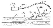
- FIG. 4is a perspective view of one type of automated endovascular heat exchange system incorporating an introducer sheath/temperature probe assembly of the present invention.
- FIG. 5is a side elevational view of the heat exchange catheter component of the automated endovascular heat exchange system of FIG. 4 .
- FIG. 5Ais a cross-sectional view through line 5 A— 5 A of FIG. 5 .
- FIG. 5Bis a cross-sectional view through line 5 B— 5 B of FIG. 5 .
- FIG. 5Cis a cross-sectional view through line 5 C— 5 C of FIG. 5 .
- FIG. 5Dis a cross-sectional view through line 5 D— 5 D of FIG. 5 .
- FIG. 6is an enlarged, perspective view of the portion of the heat exchange catheter within circle 6 of FIG. 5 .
- FIG. 7is an enlarged, perspective view of the portion of the heat exchange catheter within circle 7 of FIG. 5 .
- FIGS. 1 and 2B through 2 C and 2 C-A through 2 C-Cshow an example of an introducer sheath/temperature probe assembly 10 of the present invention.
- This assembly 10comprises an introducer sheath component 10 A and a temperature probe component 10 B.
- the introducer sheath component 10 Aas shown in FIG. 2A , comprises an introducer cannula 12 which has a distal end DE and a proximal end PE.
- a first hub 14is attached to the proximal end of the introducer cannula.
- An engagement surface 33 Asuch as a helical thread is formed on the outer aspect of the proximal portion of the introducer hub 14 .
- a hollow bore(not shown) extends longitudinally through the hub 14 from an opening 15 formed in the proximal end of the hub 14 into the lumen (not shown) of the cannula 12 .
- a hemostatic valve 20(not visible on figures), such as a duck bill valve, is mounted within the bore of the hub 14 to prevent blood from back-flowing out of the proximal opening 15 when the cannula 12 is inserted into a blood vessel.
- a side tube 16extends from the side of the hub 14 to permit infusion of fluids or substances into the bore of the hub 14 and through the lumen of the cannula 12 .
- One arm 17 of a three-way stopcock 18is attached to the proximal end of the side tube 15 .
- the other arms 19 a , 19 b of the stopcock 18are in the form of luer fittings so as to facilitate the connection of syringes and/or solution administration tubes to the stopcock 18 , as is well known in the art.
- the side armwill often require the suspension of taking temperature signals for a period of time after the infusion, and may require the removal of the probe from the introducer for a period of time to facilitate the injection through the side arm.
- the temperature probe component 10 Bcomprises an elongate temperature probe 32 that is sized for insertion through the proximal opening 15 of the introducer hub 14 , through the hemostatic valve 20 and through the lumen of the introducer cannula 12 .
- First and second temperature sensors 40 A, 40 Bare positioned within the elongate probe 32 . These temperature sensors 40 A, 40 B are connected by wire pairs 42 A, 42 B to female connectors 44 A, 44 B.
- the wire pairs 42 A, 42 Bextend through cable 36 and the female connectors 44 A, 44 B are positioned within plug 38 to facilitate connection to corresponding male connectors on the controller 292 of heater/cooler/control unit 270 , as shown in FIG. 4 .
- a second hubwhich may be in the form of a concave cap member 34 having an engagement surface 33 B such as a helical thread formed on its inner aspect, is provided as part of the introducer assembly and the probe 32 extends through a sealed opening in the center of the cap member 34 .
- the temperature probe component 10 Bmay be constructed by first attaching the atraumatic distal tip member 46 to the distal end of a plastic tube 47 .
- the temperature sensors 40 A, 40 Be.g., thermistors
- a glue, adhesive, weldment or other suitable meansto the distal portion of a rigid stylet 43 (such as a solid metal rod).
- a quantity of ultraviolet (UV) curable adhesiveis placed within the distal end of the tube 47 , just proximal to the previously attached atraumatic tip member 46 .
- the wire pairs 42 A, 42 Bare then drawn taut along side of the stylet 43 to which the sensors 40 A, 40 B had been attached and the stylet 43 is then inserted into the tube 47 such that the distal end of the stylet 43 and the sensors 40 A, 40 B become immersed within the quantity of ultraviolet (UV) curable adhesive that had been placed within the distal end of the tube 47 . Thereafter, a UV light is shone through the wall of the tube 47 to cure the adhesive, thereby securing the stylet 43 , sensors 40 A, 40 B within the tube 47 .
- UVultraviolet
- proximal segments of the wire pairs 42 A, 42 Bare then drawn through the lumen of flexible tube 36 and the proximal end of tube 47 containing stylet 43 is received within and secured (e.g., by adhesive) to the distal end of the flexible tube 36 , as shown in FIGS. 2 C and 2 C–B.
- Plug connectors 44 A, 44 Bare then connected to the proximal ends of the wire pairs 42 A, 42 B that extend out of the distal end of the flexible tube 36 and such plug connectors are inserted within plug housing 38 , thus completing the construction of the temperature probe assembly 10 B.
- the cap member 34When the temperature probe 32 is inserted through the proximal opening 15 of the introducer hub 14 , through the hemostatic valve 20 and through the lumen of the introducer cannula to its operative position within the introducer cannula 12 , the cap member 34 may be screwed onto the proximal end of the introducer hub 15 such that the engagement surfaces 33 A and 33 B engage one another and hold the cap member 34 on the introducer hub 114 .
- a gripping member 35such as a compressible O-ring or Tui Borst valve having an opening of variable diameter may be mounted within the cap member 34 such that the probe 32 extends through a central opening within the gripping member 34 .
- the gripping member 30will constrict about the temperature probe 34 , thereby forming a seal and holding the probe 34 in substantially fixed longitudinal position within the introducer cannula 12 .
- an atraumatic tip member 46is attached to or formed on the distal end of the temperature probe 32 and the temperature probe 32 is held in a position whereby all or a substantial portion of the atraumatic tip member 46 protrudes out of and beyond the distal end DE of the introducer cannula 12 .
- the sensors 40 A, 40 Bmay reside just within the introducer cannula, and the atraumatic tip 46 of the probe is all that protrudes out of the distal end DE of the introducer cannula. It has been found that even if the sensors do not exit the cannula and reside directly in the bloodstream, they none-the-less sense an accurate temperature of the bloodstream. This has been found to be true when the core body temperature is static, or even if the core body temperature is changing, as when an endovascular temperature system is operating to cool a patient described below. The sensors themselves may be rather stiff and thus are less traumatic to the vessel if they remain in the introducer sheath.
- the distal end DE of the introducer sheathis less traumatic if there is a soft extension which tapers gently down extending out of the blunt end of the tube itself.
- the probe 32may be placed within the introducer cannula 12 so that the introducer cannula 12 surrounds and protects the sensors 40 A, 40 B but such that the atraumatic distal tip 46 protrudes out of and beyond the distal end of the introducer cannula 12 .
- the distal tipmay be coated with a lubricious coating to enhance ease of insertion and to increase the atraumatic nature of the tip with the vessel wall. A coating which is both anti-thrombogenic and lubricious is highly advantageous since it would simultaneously aid the probe in being non-thrombogenetic and increase the atraumatic nature of the tip.
- the length, diameter and relative stiffness of the introducer cannula 12 , probe 32 and the probe's atraumatic tip member 46may vary, depending on the type and size of blood vessel into which the assembly 10 is to be inserted.
- the introducer cannulawill preferably be 7.5–14 cm in length, 2 French to 6 French in inner diameter and may be made of high density polyethylene or other suitable material having a Durometer hardness of about 72D, and the probe 32 will preferably be of a length and diameter that allows it to fit snugly but slidably within the lumen of the introducer cannula 12 .
- the probe's atraumatic tip member 46will preferably be approximately 5 cm in length and will be made of material having a Durometer hardness of 25D–35D and configured to minimize trauma to the blood vessel wall (e.g., having a rounded, blunt distal tip). It is preferable that all or substantially all of the atraumatic tip member 46 protrude beyond the distal end DE of the cannula 12 .
- the temperature sensors 40 A, 40 Bare preferably positioned on or in the probe 32 proximal to the atraumatic tip member 46 and are housed within the cannula 21 when the probe 32 is fully advanced to its operative position with its atraumatic distal tip member 46 protruding out of the distal end of the cannula 12 .
- a mark 37may be formed on the tube 36 such that the temperature probe 32 may be advanced into the cannula 12 until the mark 37 is at a predetermined location relative to the cap member 34 (e.g., where the mark 37 if immediately adjacent to the flat proximal surface 34 PS of the cap member 34 ) and the cap member 34 may then be tightened, thereby holding the probe 32 within the cannula 12 in a position where the atraumatic tip member 46 protrudes out of the distal end of the cannula 12 but the probe's sensors 42 A, 42 B remain positioned within the cannula 12 .
- FIGS. 3A–3Cshow an example of a method for inserting the introducer sheath/temperature probe assembly 10 into a blood vessel, such as a femoral vein.
- a needle Nis initially positioned within the introducer cannula 12 such that the distal end of the needle N protrudes out of the distal end of the cannula 12 and a syringe S containing a small amount of liquid, such as sterile 0.9% NaCl solution, is attached to the proximal end of the needle N.
- the needle N and cannula 12are then advanced percutaneously through the skin and underlying tissue while the operator draws back slightly on the plunger of the syringe, until the distal end of the needle enters the lumen of the blood vessel BV and a small amount of blood flows back into the barrel of the syringe S.
- the syringe S and needle Nare removed, leaving the cannula 12 within the blood vessel BV.
- the hemostatic valve 20 positioned within the introducer hub 14prevents blood from backflowing from the out of the proximal opening 15 of the introducer hub 14 .
- the temperature probe 32is inserted through the proximal opening 15 of the introducer hub 14 , through its hemostatic valve 20 , and into the lumen of the introducer cannula 12 to a position where the atraumatic distal tip member 46 protrudes out of the distal end of the introducer cannula 12 but the probe's temperature sensors 40 A, 40 B are positioned within the cannula 12 .
- the cap member 34is rotatably advanced onto the proximal end of the cannula hub 14 so that the threaded engagement surfaces 33 A, 33 B engage one another and the gripping member 35 becomes constricted about the shaft of the probe 32 , thereby holding the probe 32 in substantially fixed longitudinal position within the cannula 12 .
- the temperature probe's connector 38is connected to a controller apparatus 292 which receives and processes temperature signals from the temperature sensors 40 A, 40 B, as described more fully herebelow.
- FIG. 1Various types of heat exchange catheters and related apparatus may be used in conjunction with the introducer sheath/temperature probe assembly 10 to alter and/or control the temperature of all or a portion of the body of a human or veterinary patient. Examples of such heat exchange catheters and related apparatus are described in U.S. Pat. Nos. 6,149,676 and 6,149,676 and co-pending U.S. patent application Ser. Nos. 09/138,830, 09/563,946 and 09/707,257, the entireties of which are expressly incorporated herein by reference. FIG.
- FIG. 4shows one particular endovascular heat exchange system 101 which comprises an introducer sheath/temperature probe assembly 10 of the present invention in combination with a re-usable heater/cooler/control unit 270 and a plurality of disposable components including a heat exchange catheter 260 , a heat exchange cassette 276 , a saline bag or fluid reservoir 278 and a plurality of fluid flow conduits including a two-way conduit 267 which extends from the heat exchange cassette 276 to the proximal hub 266 of the heat exchange catheter 260 .
- the system 101may further include one or more additional body temperature probes or sensors 265 .
- Such additional body temperature probes or sensor(s) 265may be desirable in cases where the temperature probe component 30 of the introducer sheath/temperature probe assembly 10 includes only a single temperature sensor 40 a or 40 b rather than redundant, multiple temperature sensors 40 a and 40 b , as described hereabove, of if a temperature signal from a different location is desired.
- the re-usable heater/cooler/control unit 270includes an outer housing 284 having a cassette insertion slot 285 into which the heat exchange cassette 276 may be inserted.
- a heater/cooler 288such as a thermoelectric plate, a pump driver 290 , and a microprocessor controller 292 are positioned within the housing 284 .
- a manual input unit 294enables an operator to enter desirable operating parameters into the microprocessor controller 292 , for example a pre-selected target body temperature.
- Each of the electronic devices provided within the control unit 270communicate through suitable wiring or other connections.
- a wire 36 or other connectionconnects the temperature probe component 30 of the introducer sheath/temperature probe assembly 10 to the microprocessor controller 292
- another wire or other connectione.g., a wireless connection or fiber optic connection
- another wire or other connectione.g., a wireless connection or fiber optic connection
- the microprocessor controller 292receives signals or information indicating at least 1) the patient's body temperature as sensed by the introducer sheath/temperature probe assembly 10 and any optional additional body temperature sensors 265 , 2) the target body temperature and any other parameters or targets (e.g., maximum rate of cooling or warming) input by the operator through the manual input unit 294 , 3) the temperature and/or flow rate of thermal transfer fluid through the heat exchange catheter 260 as sensed by temperature and/or flow rate sensor 261 .
- other sensed or operator-input parameters or variablesmay also be received by the microprocessor controller 292 .
- the heat exchange catheter 260may comprise any suitable type of catheter designed to exchange heat with the patients blood, including those heat exchange catheters described in U.S. Pat. No. 5,486,208 (Ginsburg), PCT International Publication WO 00/10494 (Machold et al.), U.S. Pat. No. 6,264,679 (Keller et al.), PCT International Publication Nos. WO-00/10494 (Radiant Medical, Inc.) and WO 01/58397 (Radiant Medical, Inc.) U.S. Pat. No. 5,411,392 (Saab), U.S. Pat. No. 6,126,684 (Gobin et al.) And U.S. Pat. No.
- FIGS. 4–5DOne presently preferred heat exchange catheter 260 for use with this system 101 is shown in FIGS. 4–5D .
- This particular heat exchange catheter 260comprises a flexible catheter shaft 264 , a proximal hub 266 and a heat exchange balloon 268 .
- a working lumen 271extends from a proximal port 268 formed in the hub 266 , through the catheter shaft 264 and through a distal opening 269 formed in the distal end of the catheter shaft 264 .
- This working lumen 271may be used as a guidewire lumen, or for passage of various optional apparatus, sensors, probes or other devices 273 (e.g, temperature monitoring probes, pH measuring probes, etc.) and/or for injection/infusion of substances (e.g., radiographic contrast medium, drugs, fluids, etc.). Additionally an inflow lumen 296 extends from an inflow port 297 on the catheter hub 266 into the interior of the heat exchange balloon 268 and an outflow lumen 298 extends from the interior of the heat exchange balloon 268 to an outflow port 299 on the catheter hub 266 .
- sensors, probes or other devices 273e.g, temperature monitoring probes, pH measuring probes, etc.
- substancese.g., radiographic contrast medium, drugs, fluids, etc.
- Two way flow conduit 267has inflow and outflow lumens (not shown) extending therethrough. Bifurcations are formed on both ends of the two way flow conduit 267 , as shown in FIG. 4 .
- the inflow lumen of the two way flow conduit 267is connected between the inflow port 297 of catheter hub 266 and an outflow port 275 on the heat exchange cassette 276 and the outflow lumen of the two way flow conduit 267 is connected between the outflow port 299 of catheter hub 266 and an inflow port 277 on the heat exchange cassette 276 .
- one example of a heat exchange balloon 268comprises a multi-lobed structure.
- the exact number of balloon lobesmay vary depending on the particular application for which the heat exchange catheter 260 is being used and/or the size of the blood vessel in which the heat exchange balloon 268 is to be positioned.
- the heat exchange balloon 268when fully inflated, will have a maximum diameter that is at least slightly smaller than the internal diameter of the blood vessel lumen in which it is positioned, thereby allowing blood to flow freely around the inflated heat exchange balloon 268 .
- the heat exchange balloon 268comprises four (4) tubular lobes, a central lobe 300 and three (3) outer lobes 302 , 304 , 306 that are helically wound about the central lobe 300 .
- the catheter shaft 264extends into and is joined with the central lobe 300 of the balloon. As may be appreciated particularly from the showings of FIGS.
- the outflow lumen 298 of the catheter shaft 264is connected via outflow slots 310 to the interior of the heat exchange balloon 268 such that heat transfer fluid may flow from the interior of the heat exchange balloon 268 , through outflow slots 310 , through outflow lumen 298 , though outflow port 299 of catheter hub 266 , through the outflow lumen of two way conduit 267 and into the interior of the heat exchange cassette 276 through its inflow port 277 . As shown in FIGS.
- a medial catheter shaft 264 Mwhich includes a continuation of the inflow lumen 296 and working lumen 271 extends distally through the central lobe 300 of the heat exchange balloon 268 beyond the outflow slots 310 to the distal portion of the balloon where the inflow lumen 296 is connected to the interior of the heat exchange balloon 268 through inflow slots 312 .
- a pump 293 mounted within the cassette 276may pump heat transfer fluid from the open inner chamber of the cassette 276 , through a convoluted or serpentine flow path defined by a convoluted or serpentine bulkhead or flow director 277 positioned within the cassette 276 , through the outflow port 275 of the cassette 276 , through the inflow lumen of two way conduit 267 , through the inflow port 297 on catheter hub 266 , through the inflow lumen 296 of catheter shaft 264 and medial catheter shaft 264 M, through inflow slots 312 and into the interior of the heat exchange balloon 268 .
- heat transfer fluid that has become heated or cooled within the cassette 276will enter the distal portion of the heat exchange balloon and circulate generally in the proximal direction, exiting from the proximal portion of the heat exchange balloon 268 .
- the heat exchange catheter 260 with its heat exchange balloon 268 in a non-inflated, collapsed stateis percutaneously inserted using a Seldinger technique into a femoral vein of the patient.
- the heat exchange catheteris then advanced to a position wherein the heat exchange balloon 268 is positioned within the patient's inferior vena cava (IVC).
- IVCinferior vena cava
- An introducer sheath/temperature probe assembly 10 of the present inventionis inserted into the other femoral vein (or any other suitable blood vessel wherein the blood temperature is representative of the body temperature that the operator desires to control or alter.
- the operatorwill desire to alter or control the patient's core body temperature and, thus, it will be desirable to insert the introducer sheath/temperature probe assembly 10 into a major blood vessel wherein the flowing blood is at or near the patient's core body temperature (e.g., femoral vein, femoral artery, external jugular vein, subclavian vein, etc.).
- a major blood vesselwherein the flowing blood is at or near the patient's core body temperature (e.g., femoral vein, femoral artery, external jugular vein, subclavian vein, etc.).
- the heat transfer fluidis then transferred from the bag or vessel 278 to fill the cassette 276 , both lumens of the two way flow conduit 267 , the inflow 296 and outflow 298 lumens of the proximal and medial portions of the heat exchange catheter shaft 264 , 264 M and the lobes 300 , 302 , 304 , 306 of the heat exchange balloon 268 .
- the cassette 276is inserted into the cassette receiving slot 285 such that the cassette is positioned adjacent to the heater/cooler 288 and the pump driver 290 engages the pump 293 .
- the connector or plug 38 of the introducer sheath/temperature probe assembly 10is connected to a corresponding receptacle on the controller 292 of the heating/cooling/control unit 270 and the operator inputs the target body temperature into the input apparatus 294 .
- the system 101is then energized and the controller receives the temperature signals from the temperature sensors 40 A, 40 B within the probe 32 and compares the sensed temperatures. If the difference between the temperatures sensed by the first sensor 40 A and the second sensor 40 B is greater than the preset allowable difference (e.g., 1 degree difference) the controller will issue a warning signal to the operator and/or will automatically shut down or prevent start up of the pump driver 290 , thereby stopping or preventing any heat transfer fluid from being circulated through the heat exchange balloon 268 .
- the preset allowable differencee.g. 1 degree difference
- the controllerwill average the two sensed temperatures and that average will be taken as the current measured body temperature to use as the “driver” temperature.
- the controllermay compare the two signals, and if they are within the predetermined range (e.g. 1 degree C. or 10% or some other appropriate criteria) the controller may ignore one and use the temperature signal from the other as the temperature signal to drive the controller.
- the controllermay compare the two signals and select one based on some other criteria, for example if the controller is cooling the patient's body, the controller may select the cooler of the two temperatures as the “driver” temperature to use, and thus avoid overcooling the patient, or if the controller is warming, it may select the warmer of the two as the “driver” temperature signal. If three signals are compared, the controller could also use the median temperature signal as the “driver” signal.
- the controller 292compares this current body temperature to the target body temperature that had been entered by the operator and, if the current measured body temperature is different from the target temperature, the controller will cause the heater/cooler to either heat or cool the heat transfer fluid within the cassette 276 and/or will adjust the rate at which the driver 290 drives the pump 293 such that the temperature of the heat transfer fluid being circulated through the heat exchange balloon 268 and/or the rate at which the heat transfer fluid is circulated through the heat exchange balloon 268 will cause warming or cooling of the patient's blood until the current measured body temperature reaches the target temperature.
- the controller 292may be specifically programmed to minimize or prevent overshoot of the target temperature as described in U.S. Pat. No. 5,837,003 (Ginsburg) and U.S.
Landscapes
- Health & Medical Sciences (AREA)
- Life Sciences & Earth Sciences (AREA)
- Engineering & Computer Science (AREA)
- Public Health (AREA)
- Veterinary Medicine (AREA)
- Physics & Mathematics (AREA)
- General Health & Medical Sciences (AREA)
- Animal Behavior & Ethology (AREA)
- Biomedical Technology (AREA)
- Heart & Thoracic Surgery (AREA)
- Medical Informatics (AREA)
- Molecular Biology (AREA)
- Surgery (AREA)
- Pathology (AREA)
- Biophysics (AREA)
- Thermal Sciences (AREA)
- Vascular Medicine (AREA)
- Physiology (AREA)
- Computer Networks & Wireless Communication (AREA)
- Surgical Instruments (AREA)
Abstract
Description
Claims (112)
Priority Applications (4)
| Application Number | Priority Date | Filing Date | Title |
|---|---|---|---|
| US10/238,925US7186222B1 (en) | 2002-09-10 | 2002-09-10 | Vascular introducer with temperature monitoring probe and systems for endovascular temperature control |
| US11/709,108US7946996B2 (en) | 2002-09-10 | 2007-02-20 | Vascular introducer with temperature monitoring probe and systems for endovascular temperature control |
| US13/115,000US8821406B2 (en) | 2002-09-10 | 2011-05-24 | Vascular introducer with temperature monitoring probe and systems for endovascular temperature control |
| US14/445,892US9357967B2 (en) | 2002-09-10 | 2014-07-29 | Vascular sheath with temperature monitoring probe |
Applications Claiming Priority (1)
| Application Number | Priority Date | Filing Date | Title |
|---|---|---|---|
| US10/238,925US7186222B1 (en) | 2002-09-10 | 2002-09-10 | Vascular introducer with temperature monitoring probe and systems for endovascular temperature control |
Related Parent Applications (1)
| Application Number | Title | Priority Date | Filing Date |
|---|---|---|---|
| US11/709,108ContinuationUS7946996B2 (en) | 2002-09-10 | 2007-02-20 | Vascular introducer with temperature monitoring probe and systems for endovascular temperature control |
Related Child Applications (2)
| Application Number | Title | Priority Date | Filing Date |
|---|---|---|---|
| US11/709,108ContinuationUS7946996B2 (en) | 2002-09-10 | 2007-02-20 | Vascular introducer with temperature monitoring probe and systems for endovascular temperature control |
| US13/115,000ContinuationUS8821406B2 (en) | 2002-09-10 | 2011-05-24 | Vascular introducer with temperature monitoring probe and systems for endovascular temperature control |
Publications (1)
| Publication Number | Publication Date |
|---|---|
| US7186222B1true US7186222B1 (en) | 2007-03-06 |
Family
ID=37807084
Family Applications (4)
| Application Number | Title | Priority Date | Filing Date |
|---|---|---|---|
| US10/238,925Expired - LifetimeUS7186222B1 (en) | 2002-09-10 | 2002-09-10 | Vascular introducer with temperature monitoring probe and systems for endovascular temperature control |
| US11/709,108Expired - Fee RelatedUS7946996B2 (en) | 2002-09-10 | 2007-02-20 | Vascular introducer with temperature monitoring probe and systems for endovascular temperature control |
| US13/115,000Expired - Fee RelatedUS8821406B2 (en) | 2002-09-10 | 2011-05-24 | Vascular introducer with temperature monitoring probe and systems for endovascular temperature control |
| US14/445,892Expired - Fee RelatedUS9357967B2 (en) | 2002-09-10 | 2014-07-29 | Vascular sheath with temperature monitoring probe |
Family Applications After (3)
| Application Number | Title | Priority Date | Filing Date |
|---|---|---|---|
| US11/709,108Expired - Fee RelatedUS7946996B2 (en) | 2002-09-10 | 2007-02-20 | Vascular introducer with temperature monitoring probe and systems for endovascular temperature control |
| US13/115,000Expired - Fee RelatedUS8821406B2 (en) | 2002-09-10 | 2011-05-24 | Vascular introducer with temperature monitoring probe and systems for endovascular temperature control |
| US14/445,892Expired - Fee RelatedUS9357967B2 (en) | 2002-09-10 | 2014-07-29 | Vascular sheath with temperature monitoring probe |
Country Status (1)
| Country | Link |
|---|---|
| US (4) | US7186222B1 (en) |
Cited By (33)
| Publication number | Priority date | Publication date | Assignee | Title |
|---|---|---|---|---|
| US20060079885A1 (en)* | 2004-10-08 | 2006-04-13 | Rick Kyle R | Cool-tip combined electrode introducer |
| US20060079887A1 (en)* | 2004-10-08 | 2006-04-13 | Buysse Steven P | Electrosurgical system employing multiple electrodes and method thereof |
| US20060100595A1 (en)* | 2004-11-09 | 2006-05-11 | Von Dyck Peter M | Bowel management system with physiologic sensors |
| US20070066971A1 (en)* | 2005-09-21 | 2007-03-22 | Podhajsky Ronald J | Method and system for treating pain during an electrosurgical procedure |
| US20070073285A1 (en)* | 2005-09-27 | 2007-03-29 | Darion Peterson | Cooled RF ablation needle |
| US20070078454A1 (en)* | 2005-09-30 | 2007-04-05 | Mcpherson James W | System and method for creating lesions using bipolar electrodes |
| US20070078453A1 (en)* | 2005-10-04 | 2007-04-05 | Johnson Kristin D | System and method for performing cardiac ablation |
| US20070258838A1 (en)* | 2006-05-03 | 2007-11-08 | Sherwood Services Ag | Peristaltic cooling pump system |
| US20080021448A1 (en)* | 2004-10-08 | 2008-01-24 | Orszulak James H | Electrosurgical system employing multiple electrodes and method thereof |
| US20080027424A1 (en)* | 2006-07-28 | 2008-01-31 | Sherwood Services Ag | Cool-tip thermocouple including two-piece hub |
| US20080119757A1 (en)* | 2006-11-21 | 2008-05-22 | Suzanne Winter | Temperature management system with wireless patient temperature sensor |
| US20080183165A1 (en)* | 2007-01-31 | 2008-07-31 | Steven Paul Buysse | Thermal Feedback Systems and Methods of Using the Same |
| US20080319438A1 (en)* | 2007-06-22 | 2008-12-25 | Decarlo Arnold V | Electrosurgical systems and cartridges for use therewith |
| US20090138005A1 (en)* | 2007-11-27 | 2009-05-28 | Vivant Medical, Inc. | Targeted Cooling of Deployable Microwave Antenna |
| US20090149850A1 (en)* | 2002-04-16 | 2009-06-11 | Vivant Medical, Inc. | Localization Element with Energized Tip |
| US20090157041A1 (en)* | 2001-09-12 | 2009-06-18 | Pettis Ronald J | Microneedel-based pen device for drug delivery and method for using same |
| US20100023007A1 (en)* | 2008-07-22 | 2010-01-28 | Sartor Joe D | Electrosurgical devices, systems and methods of using the same |
| US20100256735A1 (en)* | 2009-04-03 | 2010-10-07 | Board Of Regents, The University Of Texas System | Intraluminal stent with seam |
| US8181995B2 (en) | 2007-09-07 | 2012-05-22 | Tyco Healthcare Group Lp | Cool tip junction |
| US8343097B2 (en) | 2005-12-22 | 2013-01-01 | Hybernia Medical Llc | Systems and methods for intravascular cooling |
| US8668688B2 (en) | 2006-05-05 | 2014-03-11 | Covidien Ag | Soft tissue RF transection and resection device |
| US8821406B2 (en) | 2002-09-10 | 2014-09-02 | Zoll Circulation, Inc. | Vascular introducer with temperature monitoring probe and systems for endovascular temperature control |
| EP2886150A1 (en)* | 2013-12-20 | 2015-06-24 | Delta Med S.P.A. Unipersonale | Jugular catether |
| US9579150B2 (en) | 2011-04-08 | 2017-02-28 | Covidien Lp | Microwave ablation instrument with interchangeable antenna probe |
| US20170119461A1 (en)* | 2015-10-29 | 2017-05-04 | Kyphon Sárl | Electrosurgical Apparatus with Temperature Sensing and Methods of use thereof |
| CN106823099A (en)* | 2016-12-28 | 2017-06-13 | 苏州科技城医院 | Cvc |
| US9743975B2 (en) | 2012-10-02 | 2017-08-29 | Covidien Lp | Thermal ablation probe for a medical device |
| CN110123288A (en)* | 2019-06-27 | 2019-08-16 | 上海英诺伟医疗器械有限公司 | A kind of inner cavity temperature, multifunctional monitoring device, system and guide sheath, endoscope |
| US20200281765A1 (en)* | 2016-12-30 | 2020-09-10 | Zoll Circulation, Inc. | Fluid-circulating catheters useable for endovascular heat exchange |
| WO2021011408A1 (en)* | 2019-07-12 | 2021-01-21 | Bard Access Systems, Inc. | Tubing with integrated optical fiber, medical devices, and methods thereof |
| CN112891056A (en)* | 2021-01-28 | 2021-06-04 | 云南科威液态金属谷研发有限公司 | Radio frequency thermotherapy system |
| US11135405B2 (en)* | 2011-12-22 | 2021-10-05 | Ecp Entwicklungsgesellschaft Mbh | Sheath device for inserting a catheter |
| US11576716B2 (en) | 2013-03-15 | 2023-02-14 | Medtronic Holding Company Sàrl | Electrosurgical mapping tools and methods |
Families Citing this family (14)
| Publication number | Priority date | Publication date | Assignee | Title |
|---|---|---|---|---|
| US9566185B2 (en) | 2007-10-12 | 2017-02-14 | Medivance Incorporated | System and method for patient temperature control |
| WO2009065138A1 (en) | 2007-11-16 | 2009-05-22 | Medivance Incorporated | Patient temperature response control system and method |
| US8974115B2 (en)* | 2012-04-27 | 2015-03-10 | Kinsa, Inc. | Temperature measurement system and method |
| CN106573101B (en) | 2014-08-14 | 2020-02-11 | 梅迪万斯股份有限公司 | System and method for extracorporeal blood temperature control |
| JP6787903B2 (en) | 2015-01-27 | 2020-11-18 | メディヴァンス インコーポレイテッドMedivance,Inc. | Improved medical pads and systems for hyperthermia |
| WO2019228991A1 (en)* | 2018-05-29 | 2019-12-05 | B. Braun Melsungen Ag | Peripheral venous catheter assemblies with sensors and related methods |
| US20200188684A1 (en) | 2018-12-14 | 2020-06-18 | Avent, Inc. | Polymer Introducer for Use with an RF Ablation Probe and Associated RF Ablation Probe Assembly |
| USD885560S1 (en) | 2018-12-14 | 2020-05-26 | Avent, Inc. | Introducer hub with fluid delivery port |
| EP3714777B1 (en)* | 2019-03-29 | 2022-02-16 | Welch Allyn, INC. | Sepsis detection and monitoring |
| US11309091B2 (en) | 2020-03-18 | 2022-04-19 | Kinsa Inc. | Systems and methods for contagious illness surveillance and outbreak detection |
| US12433785B2 (en) | 2021-02-23 | 2025-10-07 | C. R. Bard, Inc. | Gel pad assembly using free rotatable fluid joints |
| US12241570B2 (en) | 2021-07-07 | 2025-03-04 | C. R. Bard, Inc. | Negative pressure connector seal |
| CN118401204A (en)* | 2021-12-02 | 2024-07-26 | C·R·巴德股份有限公司 | Systems, methods and apparatus for automated feedback to a targeted temperature management system |
| GB202307199D0 (en)* | 2023-05-15 | 2023-06-28 | Neurochase Tech Ltd | Neurosurgical device |
Citations (36)
| Publication number | Priority date | Publication date | Assignee | Title |
|---|---|---|---|---|
| US2012112A (en) | 1932-05-16 | 1935-08-20 | Central Scientific Co | Thermometer |
| US2816997A (en) | 1955-02-23 | 1957-12-17 | Waters Corp | Resistance thermometer |
| US3726269A (en)* | 1971-11-24 | 1973-04-10 | W Webster | Cardiovascular catheter for thermal dilution measurement |
| US3951136A (en) | 1973-10-10 | 1976-04-20 | Vital Signs, Inc. | Multiple purpose esophageal probe |
| US3995623A (en)* | 1974-12-23 | 1976-12-07 | American Hospital Supply Corporation | Multipurpose flow-directed catheter |
| US4176660A (en) | 1978-03-10 | 1979-12-04 | University Patents, Inc. | Disposable esophageal and tracheal multi-probes |
| US4419999A (en) | 1981-04-17 | 1983-12-13 | May Jr James W | Method and apparatus for monitoring vascular flow |
| US4476872A (en) | 1980-03-07 | 1984-10-16 | The Kendall Company | Esophageal probe with disposable cover |
| US4508123A (en) | 1983-06-01 | 1985-04-02 | American Hospital Supply Corporation | Thermodilution injectate assembly |
| US4633885A (en) | 1983-04-29 | 1987-01-06 | Dubrucq Denyse C | Electronic temperature probe |
| US4796640A (en)* | 1984-01-13 | 1989-01-10 | American Hospital Supply Corporation | Apparatus with fast response thermistor |
| US4886506A (en)* | 1986-12-23 | 1989-12-12 | Baxter Travenol Laboratories, Inc. | Soft tip catheter |
| US4941475A (en) | 1988-08-30 | 1990-07-17 | Spectramed, Inc. | Thermodilution by heat exchange |
| US4950257A (en)* | 1988-09-15 | 1990-08-21 | Mallinckrodt, Inc. | Catheter introducer with flexible tip |
| US5174285A (en)* | 1990-01-08 | 1992-12-29 | Lake Shore Medical Development Partners Ltd. | Localized heat transfer device |
| US5211631A (en) | 1991-07-24 | 1993-05-18 | Sheaff Charles M | Patient warming apparatus |
| US5254097A (en)* | 1992-01-06 | 1993-10-19 | Datascope Investment Corp. | Combined percutaneous cardiopulmonary bypass (PBY) and intra-aortic balloon (IAB) access cannula |
| US5271410A (en) | 1991-04-01 | 1993-12-21 | Baxter International Inc. | Catheter with rapid response thermistor and method |
| US5334160A (en)* | 1992-05-04 | 1994-08-02 | Scimed Life Systems, Inc. | Intravascular catheter with sleeve and method for use thereof |
| US5573007A (en)* | 1994-08-08 | 1996-11-12 | Innerspace, Inc. | Gas column pressure monitoring catheters |
| US5588438A (en) | 1991-01-29 | 1996-12-31 | Interflo Medical, Inc. | System and method for controlling the temperature of a catheter-mounted heater |
| US5713371A (en)* | 1995-07-07 | 1998-02-03 | Sherman; Dani | Method of monitoring cervical dilatation during labor, and ultrasound transducer particularly useful in such method |
| US5807269A (en)* | 1991-01-29 | 1998-09-15 | Baxter International Inc. | Thermodilution catheter having a safe, flexible heating element |
| US5984879A (en)* | 1996-09-03 | 1999-11-16 | Clinical Innovation Associates, Inc. | Intrauterine pressure catheter device |
| US6126684A (en)* | 1998-04-21 | 2000-10-03 | The Regents Of The University Of California | Indwelling heat exchange catheter and method of using same |
| US6146411A (en)* | 1998-12-24 | 2000-11-14 | Alsius Corporation | Cooling system for indwelling heat exchange catheter |
| US6231594B1 (en)* | 1999-08-11 | 2001-05-15 | Radiant Medical, Inc. | Method of controlling body temperature while reducing shivering |
| US6290717B1 (en) | 1999-03-31 | 2001-09-18 | Alsius Corporation | Temperature probe and interconnect cable for hypothermia catheter temperature feedback |
| US6299599B1 (en)* | 1999-02-19 | 2001-10-09 | Alsius Corporation | Dual balloon central venous line catheter temperature control system |
| US6383144B1 (en)* | 2000-01-18 | 2002-05-07 | Edwards Lifesciences Corporation | Devices and methods for measuring temperature of a patient |
| US6419643B1 (en) | 1998-04-21 | 2002-07-16 | Alsius Corporation | Central venous catheter with heat exchange properties |
| US6575623B2 (en)* | 2000-11-10 | 2003-06-10 | Cardiostream, Inc. | Guide wire having extendable contact sensors for measuring temperature of vessel walls |
| US6592544B1 (en)* | 1999-11-24 | 2003-07-15 | Edwards Lifesciences Corporation | Vascular access devices having hemostatic safety valve |
| US6602243B2 (en)* | 2000-12-15 | 2003-08-05 | Alsius Corporation | Foley catheter having redundant temperature sensors and method |
| US6607517B1 (en)* | 2001-08-24 | 2003-08-19 | Radiant Medical, Inc. | Method of inotropic treatment of heart disease using hypothermia |
| US6866638B2 (en)* | 2002-08-12 | 2005-03-15 | Radiant Medical, Inc. | Temperature sensing system with retrograde sensor |
Family Cites Families (17)
| Publication number | Priority date | Publication date | Assignee | Title |
|---|---|---|---|---|
| US4417886A (en)* | 1981-11-05 | 1983-11-29 | Arrow International, Inc. | Catheter introduction set |
| JPS6041956A (en)* | 1983-08-19 | 1985-03-05 | 株式会社東芝 | Ultrasonic diagnostic apparatus |
| US4650472A (en)* | 1985-08-30 | 1987-03-17 | Cook, Incorporated | Apparatus and method for effecting percutaneous catheterization of a blood vessel using a small gauge introducer needle |
| US5059186A (en)* | 1988-03-07 | 1991-10-22 | Vitaphore Corporation | Percutaneous access device |
| US5624392A (en) | 1990-05-11 | 1997-04-29 | Saab; Mark A. | Heat transfer catheters and methods of making and using same |
| US5486208A (en) | 1993-02-10 | 1996-01-23 | Ginsburg; Robert | Method and apparatus for controlling a patient's body temperature by in situ blood temperature modification |
| US5837003A (en) | 1993-02-10 | 1998-11-17 | Radiant Medical, Inc. | Method and apparatus for controlling a patient's body temperature by in situ blood temperature modification |
| US6620188B1 (en) | 1998-08-24 | 2003-09-16 | Radiant Medical, Inc. | Methods and apparatus for regional and whole body temperature modification |
| US20020120200A1 (en)* | 1997-10-14 | 2002-08-29 | Brian Brockway | Devices, systems and methods for endocardial pressure measurement |
| US6088608A (en)* | 1997-10-20 | 2000-07-11 | Alfred E. Mann Foundation | Electrochemical sensor and integrity tests therefor |
| US6096068A (en) | 1998-01-23 | 2000-08-01 | Innercool Therapies, Inc. | Selective organ cooling catheter and method of using the same |
| US6620189B1 (en) | 2000-02-28 | 2003-09-16 | Radiant Medical, Inc. | Method and system for control of a patient's body temperature by way of a transluminally insertable heat exchange catheter |
| US6673098B1 (en) | 1998-08-24 | 2004-01-06 | Radiant Medical, Inc. | Disposable cassette for intravascular heat exchange catheter |
| US6264679B1 (en) | 1999-08-20 | 2001-07-24 | Radiant Medical, Inc. | Heat exchange catheter with discrete heat exchange elements |
| AU2001233337B2 (en) | 2000-02-09 | 2005-10-20 | Radiant Medical, Inc. | Multiple lumen heat exchange catheters |
| US6591123B2 (en)* | 2000-08-31 | 2003-07-08 | Mallinckrodt Inc. | Oximeter sensor with digital memory recording sensor data |
| US7186222B1 (en) | 2002-09-10 | 2007-03-06 | Radiant Medical, Inc. | Vascular introducer with temperature monitoring probe and systems for endovascular temperature control |
- 2002
- 2002-09-10USUS10/238,925patent/US7186222B1/ennot_activeExpired - Lifetime
- 2007
- 2007-02-20USUS11/709,108patent/US7946996B2/ennot_activeExpired - Fee Related
- 2011
- 2011-05-24USUS13/115,000patent/US8821406B2/ennot_activeExpired - Fee Related
- 2014
- 2014-07-29USUS14/445,892patent/US9357967B2/ennot_activeExpired - Fee Related
Patent Citations (38)
| Publication number | Priority date | Publication date | Assignee | Title |
|---|---|---|---|---|
| US2012112A (en) | 1932-05-16 | 1935-08-20 | Central Scientific Co | Thermometer |
| US2816997A (en) | 1955-02-23 | 1957-12-17 | Waters Corp | Resistance thermometer |
| US3726269A (en)* | 1971-11-24 | 1973-04-10 | W Webster | Cardiovascular catheter for thermal dilution measurement |
| US3951136A (en) | 1973-10-10 | 1976-04-20 | Vital Signs, Inc. | Multiple purpose esophageal probe |
| US3995623A (en)* | 1974-12-23 | 1976-12-07 | American Hospital Supply Corporation | Multipurpose flow-directed catheter |
| US4176660A (en) | 1978-03-10 | 1979-12-04 | University Patents, Inc. | Disposable esophageal and tracheal multi-probes |
| US4476872A (en) | 1980-03-07 | 1984-10-16 | The Kendall Company | Esophageal probe with disposable cover |
| US4419999A (en) | 1981-04-17 | 1983-12-13 | May Jr James W | Method and apparatus for monitoring vascular flow |
| US4633885A (en) | 1983-04-29 | 1987-01-06 | Dubrucq Denyse C | Electronic temperature probe |
| US4508123A (en) | 1983-06-01 | 1985-04-02 | American Hospital Supply Corporation | Thermodilution injectate assembly |
| US4796640A (en)* | 1984-01-13 | 1989-01-10 | American Hospital Supply Corporation | Apparatus with fast response thermistor |
| US4886506A (en)* | 1986-12-23 | 1989-12-12 | Baxter Travenol Laboratories, Inc. | Soft tip catheter |
| US4941475A (en) | 1988-08-30 | 1990-07-17 | Spectramed, Inc. | Thermodilution by heat exchange |
| US4950257A (en)* | 1988-09-15 | 1990-08-21 | Mallinckrodt, Inc. | Catheter introducer with flexible tip |
| US5174285A (en)* | 1990-01-08 | 1992-12-29 | Lake Shore Medical Development Partners Ltd. | Localized heat transfer device |
| US5588438A (en) | 1991-01-29 | 1996-12-31 | Interflo Medical, Inc. | System and method for controlling the temperature of a catheter-mounted heater |
| US5807269A (en)* | 1991-01-29 | 1998-09-15 | Baxter International Inc. | Thermodilution catheter having a safe, flexible heating element |
| US5271410A (en) | 1991-04-01 | 1993-12-21 | Baxter International Inc. | Catheter with rapid response thermistor and method |
| US5211631A (en) | 1991-07-24 | 1993-05-18 | Sheaff Charles M | Patient warming apparatus |
| US5254097A (en)* | 1992-01-06 | 1993-10-19 | Datascope Investment Corp. | Combined percutaneous cardiopulmonary bypass (PBY) and intra-aortic balloon (IAB) access cannula |
| US5334160A (en)* | 1992-05-04 | 1994-08-02 | Scimed Life Systems, Inc. | Intravascular catheter with sleeve and method for use thereof |
| US5573007A (en)* | 1994-08-08 | 1996-11-12 | Innerspace, Inc. | Gas column pressure monitoring catheters |
| US5713371A (en)* | 1995-07-07 | 1998-02-03 | Sherman; Dani | Method of monitoring cervical dilatation during labor, and ultrasound transducer particularly useful in such method |
| US5984879A (en)* | 1996-09-03 | 1999-11-16 | Clinical Innovation Associates, Inc. | Intrauterine pressure catheter device |
| US6126684A (en)* | 1998-04-21 | 2000-10-03 | The Regents Of The University Of California | Indwelling heat exchange catheter and method of using same |
| US6652565B1 (en)* | 1998-04-21 | 2003-11-25 | Alsius Corporation | Central venous catheter with heat exchange properties |
| US6419643B1 (en) | 1998-04-21 | 2002-07-16 | Alsius Corporation | Central venous catheter with heat exchange properties |
| US6146411A (en)* | 1998-12-24 | 2000-11-14 | Alsius Corporation | Cooling system for indwelling heat exchange catheter |
| US6454792B1 (en)* | 1998-12-24 | 2002-09-24 | Alsius Corporation | Cooling system for indwelling heat exchange catheter |
| US6299599B1 (en)* | 1999-02-19 | 2001-10-09 | Alsius Corporation | Dual balloon central venous line catheter temperature control system |
| US6290717B1 (en) | 1999-03-31 | 2001-09-18 | Alsius Corporation | Temperature probe and interconnect cable for hypothermia catheter temperature feedback |
| US6231594B1 (en)* | 1999-08-11 | 2001-05-15 | Radiant Medical, Inc. | Method of controlling body temperature while reducing shivering |
| US6592544B1 (en)* | 1999-11-24 | 2003-07-15 | Edwards Lifesciences Corporation | Vascular access devices having hemostatic safety valve |
| US6383144B1 (en)* | 2000-01-18 | 2002-05-07 | Edwards Lifesciences Corporation | Devices and methods for measuring temperature of a patient |
| US6575623B2 (en)* | 2000-11-10 | 2003-06-10 | Cardiostream, Inc. | Guide wire having extendable contact sensors for measuring temperature of vessel walls |
| US6602243B2 (en)* | 2000-12-15 | 2003-08-05 | Alsius Corporation | Foley catheter having redundant temperature sensors and method |
| US6607517B1 (en)* | 2001-08-24 | 2003-08-19 | Radiant Medical, Inc. | Method of inotropic treatment of heart disease using hypothermia |
| US6866638B2 (en)* | 2002-08-12 | 2005-03-15 | Radiant Medical, Inc. | Temperature sensing system with retrograde sensor |
Non-Patent Citations (1)
| Title |
|---|
| "The Subclavian Vein," Central Venous Access and Monitoring. Update in Anaesthesia, Issue 12 (2000) Article 13. http://www.nda.ox.ac.uk/wfsa/html/u1213<SUB>-</SUB>03.htm.* |
Cited By (66)
| Publication number | Priority date | Publication date | Assignee | Title |
|---|---|---|---|---|
| US10661066B2 (en) | 2001-09-12 | 2020-05-26 | Becton, Dickinson And Company | Microneedle-based pen device for drug delivery and method for using same |
| US8900186B2 (en) | 2001-09-12 | 2014-12-02 | Becton, Dickinson And Company | Microneedle-based pen device for drug delivery and method for using same |
| US20090157041A1 (en)* | 2001-09-12 | 2009-06-18 | Pettis Ronald J | Microneedel-based pen device for drug delivery and method for using same |
| US7846108B2 (en) | 2002-04-16 | 2010-12-07 | Vivant Medical, Inc. | Localization element with energized tip |
| US20090149850A1 (en)* | 2002-04-16 | 2009-06-11 | Vivant Medical, Inc. | Localization Element with Energized Tip |
| US8821406B2 (en) | 2002-09-10 | 2014-09-02 | Zoll Circulation, Inc. | Vascular introducer with temperature monitoring probe and systems for endovascular temperature control |
| US9357967B2 (en) | 2002-09-10 | 2016-06-07 | Zoll Circulation, Inc. | Vascular sheath with temperature monitoring probe |
| US8062290B2 (en) | 2004-10-08 | 2011-11-22 | Covidien Ag | Electrosurgical system employing multiple electrodes |
| US20060079887A1 (en)* | 2004-10-08 | 2006-04-13 | Buysse Steven P | Electrosurgical system employing multiple electrodes and method thereof |
| US8398626B2 (en) | 2004-10-08 | 2013-03-19 | Covidien Ag | Electrosurgical system employing multiple electrodes |
| US8377057B2 (en) | 2004-10-08 | 2013-02-19 | Covidien Ag | Cool-tip combined electrode introducer |
| US20060079885A1 (en)* | 2004-10-08 | 2006-04-13 | Rick Kyle R | Cool-tip combined electrode introducer |
| US8182477B2 (en) | 2004-10-08 | 2012-05-22 | Covidien Ag | Electrosurgical system employing multiple electrodes and method thereof |
| US20080021448A1 (en)* | 2004-10-08 | 2008-01-24 | Orszulak James H | Electrosurgical system employing multiple electrodes and method thereof |
| US20090054891A1 (en)* | 2004-10-08 | 2009-02-26 | Buysse Steven P | Electrosurgical system employing multiple electrodes and method thereof |
| US20100292686A1 (en)* | 2004-10-08 | 2010-11-18 | Rick Kyle R | Cool-Tip Combined Electrode Introducer |
| US7776035B2 (en) | 2004-10-08 | 2010-08-17 | Covidien Ag | Cool-tip combined electrode introducer |
| US7699842B2 (en) | 2004-10-08 | 2010-04-20 | Covidien Ag | Electrosurgical system employing multiple electrodes and method thereof |
| US7553309B2 (en) | 2004-10-08 | 2009-06-30 | Covidien Ag | Electrosurgical system employing multiple electrodes and method thereof |
| US9113888B2 (en) | 2004-10-08 | 2015-08-25 | Covidien Ag | Electrosurgical system employing multiple electrodes and method thereof |
| US8075540B2 (en) | 2004-11-09 | 2011-12-13 | Hollister Incorporated | Bowel management system with physiologic sensors |
| US20060100595A1 (en)* | 2004-11-09 | 2006-05-11 | Von Dyck Peter M | Bowel management system with physiologic sensors |
| US20070066971A1 (en)* | 2005-09-21 | 2007-03-22 | Podhajsky Ronald J | Method and system for treating pain during an electrosurgical procedure |
| US7879031B2 (en) | 2005-09-27 | 2011-02-01 | Covidien Ag | Cooled RF ablation needle |
| US20070073285A1 (en)* | 2005-09-27 | 2007-03-29 | Darion Peterson | Cooled RF ablation needle |
| US20070078454A1 (en)* | 2005-09-30 | 2007-04-05 | Mcpherson James W | System and method for creating lesions using bipolar electrodes |
| US20070078453A1 (en)* | 2005-10-04 | 2007-04-05 | Johnson Kristin D | System and method for performing cardiac ablation |
| US8343097B2 (en) | 2005-12-22 | 2013-01-01 | Hybernia Medical Llc | Systems and methods for intravascular cooling |
| US20070258838A1 (en)* | 2006-05-03 | 2007-11-08 | Sherwood Services Ag | Peristaltic cooling pump system |
| US8668688B2 (en) | 2006-05-05 | 2014-03-11 | Covidien Ag | Soft tissue RF transection and resection device |
| US7763018B2 (en) | 2006-07-28 | 2010-07-27 | Covidien Ag | Cool-tip thermocouple including two-piece hub |
| US9848932B2 (en) | 2006-07-28 | 2017-12-26 | Covidien Ag | Cool-tip thermocouple including two-piece hub |
| US20080287946A1 (en)* | 2006-07-28 | 2008-11-20 | Decarlo Arnold V | Cool-Tip Thermocouple Including Two-Piece Hub |
| US8672937B2 (en) | 2006-07-28 | 2014-03-18 | Covidien Ag | Cool-tip thermocouple including two-piece hub |
| US20080027424A1 (en)* | 2006-07-28 | 2008-01-31 | Sherwood Services Ag | Cool-tip thermocouple including two-piece hub |
| US20080119757A1 (en)* | 2006-11-21 | 2008-05-22 | Suzanne Winter | Temperature management system with wireless patient temperature sensor |
| US8211099B2 (en) | 2007-01-31 | 2012-07-03 | Tyco Healthcare Group Lp | Thermal feedback systems and methods of using the same |
| US8956350B2 (en) | 2007-01-31 | 2015-02-17 | Covidien Lp | Thermal feedback systems and methods of using the same |
| US8568402B2 (en) | 2007-01-31 | 2013-10-29 | Covidien Lp | Thermal feedback systems and methods of using the same |
| US8480666B2 (en) | 2007-01-31 | 2013-07-09 | Covidien Lp | Thermal feedback systems and methods of using the same |
| US9833287B2 (en) | 2007-01-31 | 2017-12-05 | Covidien Lp | Thermal feedback systems and methods of using the same |
| US20080183165A1 (en)* | 2007-01-31 | 2008-07-31 | Steven Paul Buysse | Thermal Feedback Systems and Methods of Using the Same |
| US20080319438A1 (en)* | 2007-06-22 | 2008-12-25 | Decarlo Arnold V | Electrosurgical systems and cartridges for use therewith |
| US9486269B2 (en)* | 2007-06-22 | 2016-11-08 | Covidien Lp | Electrosurgical systems and cartridges for use therewith |
| US8480665B2 (en) | 2007-09-07 | 2013-07-09 | Covidien Lp | Cool tip junction |
| US8181995B2 (en) | 2007-09-07 | 2012-05-22 | Tyco Healthcare Group Lp | Cool tip junction |
| US20090138005A1 (en)* | 2007-11-27 | 2009-05-28 | Vivant Medical, Inc. | Targeted Cooling of Deployable Microwave Antenna |
| US8292880B2 (en) | 2007-11-27 | 2012-10-23 | Vivant Medical, Inc. | Targeted cooling of deployable microwave antenna |
| US20100023007A1 (en)* | 2008-07-22 | 2010-01-28 | Sartor Joe D | Electrosurgical devices, systems and methods of using the same |
| US10524850B2 (en) | 2008-07-22 | 2020-01-07 | Covidien Lp | Electrosurgical devices, systems and methods of using the same |
| US9877769B2 (en) | 2008-07-22 | 2018-01-30 | Covidien Lp | Electrosurgical devices, systems and methods of using the same |
| US8608739B2 (en) | 2008-07-22 | 2013-12-17 | Covidien Lp | Electrosurgical devices, systems and methods of using the same |
| US20100256735A1 (en)* | 2009-04-03 | 2010-10-07 | Board Of Regents, The University Of Texas System | Intraluminal stent with seam |
| US10610298B2 (en) | 2011-04-08 | 2020-04-07 | Covidien Lp | Microwave ablation instrument with interchangeable antenna probe |
| US9579150B2 (en) | 2011-04-08 | 2017-02-28 | Covidien Lp | Microwave ablation instrument with interchangeable antenna probe |
| US11135405B2 (en)* | 2011-12-22 | 2021-10-05 | Ecp Entwicklungsgesellschaft Mbh | Sheath device for inserting a catheter |
| US9743975B2 (en) | 2012-10-02 | 2017-08-29 | Covidien Lp | Thermal ablation probe for a medical device |
| US11576716B2 (en) | 2013-03-15 | 2023-02-14 | Medtronic Holding Company Sàrl | Electrosurgical mapping tools and methods |
| EP2886150A1 (en)* | 2013-12-20 | 2015-06-24 | Delta Med S.P.A. Unipersonale | Jugular catether |
| US20170119461A1 (en)* | 2015-10-29 | 2017-05-04 | Kyphon Sárl | Electrosurgical Apparatus with Temperature Sensing and Methods of use thereof |
| CN106823099A (en)* | 2016-12-28 | 2017-06-13 | 苏州科技城医院 | Cvc |
| US20200281765A1 (en)* | 2016-12-30 | 2020-09-10 | Zoll Circulation, Inc. | Fluid-circulating catheters useable for endovascular heat exchange |
| CN110123288A (en)* | 2019-06-27 | 2019-08-16 | 上海英诺伟医疗器械有限公司 | A kind of inner cavity temperature, multifunctional monitoring device, system and guide sheath, endoscope |
| CN110123288B (en)* | 2019-06-27 | 2024-06-07 | 上海英诺伟医疗器械股份有限公司 | Inner cavity temperature and multifunctional monitoring device, system, guide sheath and endoscope |
| WO2021011408A1 (en)* | 2019-07-12 | 2021-01-21 | Bard Access Systems, Inc. | Tubing with integrated optical fiber, medical devices, and methods thereof |
| CN112891056A (en)* | 2021-01-28 | 2021-06-04 | 云南科威液态金属谷研发有限公司 | Radio frequency thermotherapy system |
Also Published As
| Publication number | Publication date |
|---|---|
| US20150025411A1 (en) | 2015-01-22 |
| US20110288432A1 (en) | 2011-11-24 |
| US9357967B2 (en) | 2016-06-07 |
| US20070173735A1 (en) | 2007-07-26 |
| US7946996B2 (en) | 2011-05-24 |
| US8821406B2 (en) | 2014-09-02 |
Similar Documents
| Publication | Publication Date | Title |
|---|---|---|
| US7186222B1 (en) | Vascular introducer with temperature monitoring probe and systems for endovascular temperature control | |
| US6719724B1 (en) | Central venous line catheter having multiple heat exchange elements and multiple infusion lumens | |
| US6520933B1 (en) | Central venous line cooling catheter having a spiral-shaped heat exchange member | |
| US6645234B2 (en) | Cardiovascular guiding catheter with heat exchange properties and methods of use | |
| US6299599B1 (en) | Dual balloon central venous line catheter temperature control system | |
| CA2368243C (en) | Central venous line catheter having temperature control system | |
| EP2255725B1 (en) | Central venous catheter with heat exchange properties | |
| US6716236B1 (en) | Intravascular catheter with heat exchange element having inner inflation element and methods of use | |
| EP1968508B1 (en) | Systems for intravascular cooling | |
| US8313461B2 (en) | Method for a central venous line catheter having a temperature control system | |
| US20040102826A1 (en) | Method and apparatus for regulating patient temperature by irrigating the bladder with a fluid | |
| EP1205167B1 (en) | Central venous line catheter having temperature control system | |
| EP1328223A2 (en) | Kit of parts including a central venous line catheter having a temperature control system |
Legal Events
| Date | Code | Title | Description |
|---|---|---|---|
| AS | Assignment | Owner name:RADIANT MEDICAL, INC., CALIFORNIA Free format text:ASSIGNMENT OF ASSIGNORS INTEREST;ASSIGNORS:CALLISTER, JEFFREY P.;DAE, MICHAEL W.;HAMMACK, AMY L;REEL/FRAME:013610/0809 Effective date:20021209 | |
| STCF | Information on status: patent grant | Free format text:PATENTED CASE | |
| AS | Assignment | Owner name:BAY CITY CAPITAL FUND IV L.P., CALIFORNIA Free format text:SECURITY AGREEMENT;ASSIGNOR:RADIANT MEDICAL, INC.;REEL/FRAME:019260/0220 Effective date:20070430 | |
| AS | Assignment | Owner name:HORIZON TECHNOLOGY FUNDING COMPANY LLC,CONNECTICUT Free format text:SECURITY AGREEMENT;ASSIGNOR:RADIANT MEDICAL, INC.;REEL/FRAME:019353/0087 Effective date:20070430 Owner name:HORIZON TECHNOLOGY FUNDING COMPANY LLC, CONNECTICU Free format text:SECURITY AGREEMENT;ASSIGNOR:RADIANT MEDICAL, INC.;REEL/FRAME:019353/0087 Effective date:20070430 | |
| AS | Assignment | Owner name:BAY CITY CAPITAL FUND IV, L.P., CALIFORNIA Free format text:ASSIGNMENT OF ASSIGNORS INTEREST;ASSIGNOR:HORIZON TECHNOLOGY FUNDING COMPANY LLC;REEL/FRAME:019781/0792 Effective date:20070906 Owner name:BAY CITY CAPITAL FUND IV, L.P.,CALIFORNIA Free format text:ASSIGNMENT OF ASSIGNORS INTEREST;ASSIGNOR:HORIZON TECHNOLOGY FUNDING COMPANY LLC;REEL/FRAME:019781/0792 Effective date:20070906 | |
| AS | Assignment | Owner name:BAY CITY CAPITAL FUND IV L.P., CALIFORNIA Free format text:SECURITY AGREEMENT;ASSIGNOR:RADIANT MEDICAL, INC.;REEL/FRAME:019805/0575 Effective date:20070907 | |
| FEPP | Fee payment procedure | Free format text:PAT HOLDER NO LONGER CLAIMS SMALL ENTITY STATUS, ENTITY STATUS SET TO UNDISCOUNTED (ORIGINAL EVENT CODE: STOL); ENTITY STATUS OF PATENT OWNER: LARGE ENTITY | |
| AS | Assignment | Owner name:ZOLL CIRCULATION, INC., CALIFORNIA Free format text:ASSIGNMENT OF ASSIGNORS INTEREST;ASSIGNORS:RADIANT MEDICAL, INC.;BAY CITY CAPITAL FUND IV, L.P.;REEL/FRAME:020679/0246 Effective date:20070918 | |
| FPAY | Fee payment | Year of fee payment:4 | |
| FPAY | Fee payment | Year of fee payment:8 | |
| MAFP | Maintenance fee payment | Free format text:PAYMENT OF MAINTENANCE FEE, 12TH YEAR, LARGE ENTITY (ORIGINAL EVENT CODE: M1553); ENTITY STATUS OF PATENT OWNER: LARGE ENTITY Year of fee payment:12 |