US7186038B2 - Telecommunications connector protective device - Google Patents
Telecommunications connector protective deviceDownload PDFInfo
- Publication number
- US7186038B2 US7186038B2US10/750,380US75038003AUS7186038B2US 7186038 B2US7186038 B2US 7186038B2US 75038003 AUS75038003 AUS 75038003AUS 7186038 B2US7186038 B2US 7186038B2
- Authority
- US
- United States
- Prior art keywords
- ferrule
- fiber optic
- plug
- connector
- optic connector
- Prior art date
- Legal status (The legal status is an assumption and is not a legal conclusion. Google has not performed a legal analysis and makes no representation as to the accuracy of the status listed.)
- Expired - Lifetime, expires
Links
Images


Classifications
- G—PHYSICS
- G02—OPTICS
- G02B—OPTICAL ELEMENTS, SYSTEMS OR APPARATUS
- G02B6/00—Light guides; Structural details of arrangements comprising light guides and other optical elements, e.g. couplings
- G02B6/24—Coupling light guides
- G02B6/36—Mechanical coupling means
- G02B6/38—Mechanical coupling means having fibre to fibre mating means
- G02B6/3807—Dismountable connectors, i.e. comprising plugs
- G02B6/3833—Details of mounting fibres in ferrules; Assembly methods; Manufacture
- G02B6/3847—Details of mounting fibres in ferrules; Assembly methods; Manufacture with means preventing fibre end damage, e.g. recessed fibre surfaces
- G02B6/3849—Details of mounting fibres in ferrules; Assembly methods; Manufacture with means preventing fibre end damage, e.g. recessed fibre surfaces using mechanical protective elements, e.g. caps, hoods, sealing membranes
- G—PHYSICS
- G02—OPTICS
- G02B—OPTICAL ELEMENTS, SYSTEMS OR APPARATUS
- G02B6/00—Light guides; Structural details of arrangements comprising light guides and other optical elements, e.g. couplings
- G02B6/44—Mechanical structures for providing tensile strength and external protection for fibres, e.g. optical transmission cables
- G02B6/4439—Auxiliary devices
- G02B6/4471—Terminating devices ; Cable clamps
Definitions
- the present inventionrelates generally to protective devices for telecommunications connectors.
- Telecommunications cablesare often pre-terminated by a manufacturer or a supplier. These pre-terminated cables may be configured to standard or customs lengths and may have one or both ends terminated.
- the connectors attached to the ends of these cablesmay be susceptible to damage or contamination during transportation from the manufacturer or supplier to a warehouse, storage facility or installation site. Damage to these connectors and cable ends may result in lost time to repair the connectors as well as possible signal degradation.
- the present inventionrelates to a cover assembly for a fiber optic connector mounted to an end of and terminating a fiber optic cable.
- the coverincludes an open sided box and a lid sized to engage the open side.
- the box and the liddefine a cavity sized to fit about and receive a fiber optic connector.
- the cavityhas an open end adapted to receive the optical fiber cable.
- the fiber optic connectoris held within the cavity and the cable extends through the open end, with the lid engaging the open side and sealing the cavity from contaminants outside the cavity.
- the present inventionrelates to a fiber optic connector assembly with a fiber optic connector mounted to a fiber optic cable and including a ferrule with an end face terminating the fiber.
- a plugis configured to fit about and engage the ferrule of the fiber optic connector to seal the end face from contaminants.
- An adhesive tapeis releasably attached to the connector about the plug, holding the plug to the connector.
- the present inventionrelates to a sleeve, the first end of which fits about a ferrule of a telecommunications connector with the end face of the ferrule within an axial opening of the sleeve.
- a plugis inserted into a second opposing end of the sleeve.
- the sleevefits closely about both the ferrule and the plug to prevent entry of airborne contaminants into the axial opening through either end.
- the present inventionrelates to a body including an axial opening with a first end and an opposing second end.
- a ferrule of a fiber optic connectoris placed within the axial opening through the first end so that a polished end face of the ferrule is within the axial opening.
- a removable adhesive sealing memberis placed over the second end of the axial opening. The body fits about the ferrule to prevent entry of airborne contaminants into the axial opening through the first end and the sealing member prevents entry of airborne contaminants into the axial opening through the second end.
- the present inventionalso relates to a method of sealing a telecommunications connector against airborne contaminants comprising terminating a fiber optic cable with a fiber optic connector in a clean environment protected against airborne contaminants. An end of an optical fiber within the cable is terminated at a polished end face of a ferrule of the connector. Within the clean environment, a seal is placed about the ferrule to protect the polished end face of the ferrule including the end of the optical fiber against airborne contaminants. The connector is then transported to a location where a fiber optic communications linkage is desired. The seal is then removed from the connector and the communications linkage is made without cleaning the end face of the connector.
- FIG. 1is a perspective view of a telecommunications connector clamshell protective device according to the present invention.
- FIG. 2is a side view of the protective device of FIG. 1 with the lid closed and the foam sealing blocks and the telecommunications cable and connector indicated with dashed lines.
- FIG. 3is a side view of a second embodiment of a telecommunications connector protective device according to the present invention with the lid closed and the foam sealing blocks and the telecommunications cable and connector indicated with dashed lines.
- FIG. 4is a perspective view of a third embodiment of a telecommunications connector plug protective device according to the present invention.
- FIG. 5is a cross-sectional view of the protective device of FIG. 4 mounted on a fiber optic connector.
- FIG. 6is a partial cross-sectional view of the protective device of FIG. 4 .
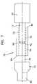
- FIG. 7is a side view of a fourth embodiment of a telecommunications connector protective device.
- FIG. 8is a side view of a fifth embodiment of a telecommunications connector protective device.
- FIG. 9is an end view of the protective device of FIG. 8 .
- Clamshell device 10includes a box 12 and a lid 14 hingedly mounted to each other by hinge 13 .
- box 12 and lid 14may be separate elements without hinge 13 or other connection extending between them.
- Connector 16is mounted to the end of and terminates a telecommunications cable 18 .
- connector 16is an optical fiber connector commonly referred to as an FC connector and cable 18 is an optical fiber cable including a strand of optical fiber terminated at a ferrule 17 .
- FC connectoroptical fiber connector
- cable 18is an optical fiber cable including a strand of optical fiber terminated at a ferrule 17 .
- Other styles and formats of optical fiber connectors and high speed copper connectorsare also contemplated within the scope of the present invention.
- the amount of data that may be transmitted through any of these connector typesmay be impeded by contaminants and use of a protective device such as device 10 may provide protection from the introduction of such contaminants.
- Connector 16is received within a recess 20 of box 12 .
- a slot 22receives cable 18 .
- Cable 18also passes across a first foam block 24 mounted within recess 20 adjacent slot 22 .
- Block 24may be formed of a deformable resilient foam to permit block 24 to conform the diameter of cable 18 and prevent entry of contaminants into recess 20 through slot 22 .
- a mating foam block 26is included on lid 14 which cooperates with block 24 to assist in sealing around cable 18 .
- either of blocks 24 or 26may be made of a material capable of conforming to the full diameter of cable 18 so that the other mating block may be formed of a relatively non-deformable material.
- the non-deformable blockmay be integrally formed as part of either lid 14 or box 12 so that fewer components are needed to assemble device 10 .
- Block 26is within a mating recess 32 of lid 14 .
- Recess 32includes perimeter walls 34 extending about lid 14 .
- Walls 34engage mating surfaces 30 of box 12 about recess 20 and cooperate to seal recesses 32 and 20 against contaminants reaching connector 16 when device 10 is closed as shown in FIG. 2 .
- Walls 34 and mating surfaces 30may be snap fit with each other when lid 14 is mated with box 12 , as shown in FIG. 2 , and the snap fit may be close enough to prevent entry of contaminants.
- walls 34 and mating surfaces 30may be bonded to each other, such as with glue, heat sealing, ultrasonic welding or other techniques, to provide additional protection against the entry of contaminants.
- FIG. 2also shows foam blocks 24 and 26 of protective device 10 of FIG. 1 cooperating to seal about cable 18 to prevent entry of contaminants into device 10 .
- Adjacent mating surfaces 30 about recess 20are flanges 36 .
- Adjacent perimeter walls 34 about recess 32are flanges 38 .
- flanges 32 and 34may be bonded to each other, such as with glue, heat sealing, ultrasonic welding or other techniques.
- FIG. 3a second embodiment of a protective device 110 is shown with a lid 114 and a box 112 connected by hinge 13 .
- Device 110differs from device 10 in that box 12 and lid 14 are approximately equal in depth, whereas box 12 is substantially deeper than lid 14 .
- Recess 32 of lid 14may only extend to the depth needed to define perimeter walls 34 .
- Recess 132 of lid 114extends to a greater depth than required to define perimeter walls 34 , as shown in FIG. 3 .
- connector 16is positioned substantially within recess 20 of box 12 and only a small portion of connector 16 extends within recess 32 of box 14 . As shown in FIG.
- connector 16extends within both recess 132 and a recess 120 of box 112 approximately equally.
- a pair of foam blocks 124 and 126are positioned adjacent an end of device 110 opposite hinge 13 to permit entry of cable 18 into device 110 and to seal about cable 18 against the entry of contaminants.
- While devices 10 and 110protect an end of cable 18 terminated at ferrule 17 from contaminants as described above, these devices also provide some protection from impact or other physical damage that may adversely affect the ability of connector 16 to interface with other elements of the telecommunications circuit.
- telecommunications connectorssuch as connector 16 include features which mate with adapters or other components and which may provide a secure and sealed interface for the transmission of signals, either optical or electrical. These mating features also need to be protected from contaminants as well as from physical damage.
- Devices 10 and 110provide protection to these mating and locking features of connector 16 as well as to ferrule or cable termination 17 .
- Plug 52for protecting an end face 50 of ferrule 17 of telecommunications connector 16 is shown.
- Plug 52includes a body 58 and a larger diameter portion 60 defining a shoulder 64 between.
- An inner cylindrical opening 56is defined within plug 52 for receiving and sealing about ferrule 17 .
- a tape 54is positioned about plug 52 to hold plug 52 to connector 16 .
- Tape 54may include an anti-tamper feature which will indicate of tape 54 has been removed and replaced or otherwise disturbed. If this anti-tamper feature indicates that tape 54 has been disturbed, this may indicate the seal between plug 52 and ferrule 17 has been broken and that end face 50 may have been exposed to contaminants.
- Tape 54may also be mounted to connector 16 and plug 52 with a tail 55 to facilitate the removal of tape 54 and plug 52 from connector 16 .
- ferrule 17is inserted within cavity 56 of plug 52 through an opening 62 .
- a tapered entry 63 into opening 62may be provided.
- a smaller diameter ledge 68is formed.
- plug 52will be made of a resilient deformable material such as a thermoplastic elastomer.
- Ledge 68should promote the formation of an airtight seal about ferrule 17 by deforming to closely match the outer surface of ferrule 17 as plug 52 is mounted to connector 16 .
- Ledge 68may also serve to brush off surface contaminants from the outer surface of ferrule 17 as plug 52 is placed about ferrule 17 and ensure that these contaminants do not enter cavity 56 . Shoulder 64 provides a finger hold to aid in the removal of plug 52 from connector 16 .
- a fourth embodiment of a protective device 70includes a plug 72 and a sleeve 74 .
- a first end 82 of sleeve 74is sized to be received about ferrule 17 of connector 16 so that end face 50 is within an axial opening 75 of sleeve 74 .
- Axial opening 75is defined by an interior wall 73 .
- axial opening 75is shown enlarged greater than the diameter of ferrule 17 for clarity.
- axial opening 75is sized to fit closely to ferrule 17 to prevent contaminants from passing through first end 82 along ferrule 17 to reach end face 50 .
- axial opening 75is consistent in diameter from first end 82 to a second end 84 .
- Plug 72includes a shaft 78 which similarly sized to ferrule 17 and is inserted through second end 84 into axial opening 75 .
- Shaft 78includes a mating portion 76 sized and shaped to approximate the polished shape of end face 50 .
- Mating portion 76is concave and forms a contour to match the polished convex shape of end face 50 .
- Mating portion 76is shown offset from end face 50 for clarity in FIG. 7 . However, in use, mating portion 76 will be in close proximity or contact with end face 50 to further provide protection against contaminants reaching end face 50 .
- Plug 72also includes an enlarged end 80 opposite shaft 78 . Enlarged end 80 provides a finger grip for removing device 70 from ferrule 17 of connector 16 .
- mating end 76is offset from end face 50 for clarity. However, end face 50 and mating face 76 would be positioned directly adjacent each other so that mating face 76 may block contaminants from reaching end face 50 . As axial opening 75 is uniform in diameter and shaft 78 is similarly sized to ferrule 17 , contaminants are prevented from entering axial opening 75 through second end 84 as well.
- a fifth embodiment of a protective device 90includes a body 96 with a flange 94 at a second end 104 .
- Body 96includes an inner wall 98 which defines an interior opening 100 extending between a first end 102 and second end 104 .
- Interior opening 100is sized to be received about ferrule 17 so that end face 50 is within opening 100 and inner wall 98 fits closely about ferrule 17 to prevent contaminants from entering opening 100 through first end 102 .
- second end 104 of body 96is open to permit ferrule 17 to be inserted within opening 100 and allowing displaced air to escape.
- an adhesive member 92such as tape, is then placed across end 104 to provide an air-tight seal of second end 104 and prevent contaminants from entering opening 100 through second end 104 .
- member 92extends beyond a flanged portion 94 of body 96 , so that member 92 may be removed to permit protective device 90 to be withdrawn from ferrule 17 .
- Flanged portion 94provides a finger grip to aid in the removal of body 96 from ferrule 17 .
- member 92could be sized to more closely match the size and shape of flanged portion 94 with a single tab extending beyond flanged portion 94 to permit removal of member 92 .
- This generalized procedurebegins with a fiber optic cable being terminated with a fiber optic connector in a clean factory environment.
- An optical fiber within the cableis positioned within a ferrule of the connector and an end face of the ferrule and the end of the fiber adjacent the end face are polished to the desired polish profile.
- the protection procedurealso includes transporting the protected connector to a location where a fiber optic communications linkage is desired.
- This locationmay be in an environment where the air is not as protected from airborne contaminants as the factory environment. Further, during transportation or storage, it is desirable that the end face of the connector be protected from airborne or other contaminants as well.
- the sealmay be removed from the connector and the linkage may be completed without the need for cleaning of the end face in the field.
- the creation of the seal about the end face and removal of the seal prior to making the linkagemay be performed by the methods and devices described above.
Landscapes
- Physics & Mathematics (AREA)
- General Physics & Mathematics (AREA)
- Optics & Photonics (AREA)
- Mechanical Coupling Of Light Guides (AREA)
Abstract
Description
Claims (5)
Priority Applications (4)
| Application Number | Priority Date | Filing Date | Title |
|---|---|---|---|
| US10/750,380US7186038B2 (en) | 2003-12-29 | 2003-12-29 | Telecommunications connector protective device |
| PCT/US2004/040401WO2005066674A2 (en) | 2003-12-29 | 2004-12-03 | Telecommunications connector protective device |
| US11/644,322US7588375B2 (en) | 2003-12-29 | 2006-12-21 | Telecommunications connector protective device |
| US12/548,091US8126307B2 (en) | 2003-12-29 | 2009-08-26 | Telecommunications connector protective device |
Applications Claiming Priority (1)
| Application Number | Priority Date | Filing Date | Title |
|---|---|---|---|
| US10/750,380US7186038B2 (en) | 2003-12-29 | 2003-12-29 | Telecommunications connector protective device |
Related Child Applications (2)
| Application Number | Title | Priority Date | Filing Date |
|---|---|---|---|
| US11/644,322ContinuationUS7588375B2 (en) | 2003-12-29 | 2006-12-21 | Telecommunications connector protective device |
| US11/644,322DivisionUS7588375B2 (en) | 2003-12-29 | 2006-12-21 | Telecommunications connector protective device |
Publications (2)
| Publication Number | Publication Date |
|---|---|
| US20050147361A1 US20050147361A1 (en) | 2005-07-07 |
| US7186038B2true US7186038B2 (en) | 2007-03-06 |
Family
ID=34711263
Family Applications (3)
| Application Number | Title | Priority Date | Filing Date |
|---|---|---|---|
| US10/750,380Expired - LifetimeUS7186038B2 (en) | 2003-12-29 | 2003-12-29 | Telecommunications connector protective device |
| US11/644,322Expired - Fee RelatedUS7588375B2 (en) | 2003-12-29 | 2006-12-21 | Telecommunications connector protective device |
| US12/548,091Expired - Fee RelatedUS8126307B2 (en) | 2003-12-29 | 2009-08-26 | Telecommunications connector protective device |
Family Applications After (2)
| Application Number | Title | Priority Date | Filing Date |
|---|---|---|---|
| US11/644,322Expired - Fee RelatedUS7588375B2 (en) | 2003-12-29 | 2006-12-21 | Telecommunications connector protective device |
| US12/548,091Expired - Fee RelatedUS8126307B2 (en) | 2003-12-29 | 2009-08-26 | Telecommunications connector protective device |
Country Status (2)
| Country | Link |
|---|---|
| US (3) | US7186038B2 (en) |
| WO (1) | WO2005066674A2 (en) |
Cited By (13)
| Publication number | Priority date | Publication date | Assignee | Title |
|---|---|---|---|---|
| US20080298749A1 (en)* | 2003-12-29 | 2008-12-04 | Adc Telecommunications, Inc. | Telecommunications connector protective device |
| US20100303434A1 (en)* | 2009-05-29 | 2010-12-02 | Ziwei Liu | Dust cap assembly for sealing an optical fiber ferrule and methods thereof |
| US20100310226A1 (en)* | 2009-06-03 | 2010-12-09 | Emerson Network Power, Energy Systems, North America, Inc. | Dust Caps for Fiber Optic Connectors |
| US20110058775A1 (en)* | 2009-06-03 | 2011-03-10 | Emerson Network Power, Energy Systems, North America, Inc. | Dust Caps for Fiber Optic Connectors |
| US8998503B2 (en) | 2012-05-16 | 2015-04-07 | Corning Cable Systems Llc | Fiber optic connector and bonded cover |
| US9411110B2 (en) | 2013-02-06 | 2016-08-09 | Corning Optical Communications LLC | Fiber optic connector cover and fiber optic assembly including same |
| US9590377B2 (en) | 2010-08-31 | 2017-03-07 | Apple Inc. | Heat sealed connector assembly |
| US9716375B1 (en)* | 2016-02-03 | 2017-07-25 | Electrolock, Inc. | Method of fabricating a protective cover from foil-backed fiberglass substrate |
| USD800660S1 (en) | 2015-06-05 | 2017-10-24 | Corning Optical Communications LLC | Fiber optic connector |
| USD800659S1 (en) | 2015-06-05 | 2017-10-24 | Corning Optical Communications LLC | Fiber optic connector |
| US10133010B2 (en) | 2015-05-29 | 2018-11-20 | Corning Optical Communications LLC | Fiber optic cable assemblies with cap apparatuses for sealing optical fiber connectors and associated methods |
| US10209456B2 (en) | 2015-05-29 | 2019-02-19 | Corning Optical Communications LLC | Fiber optic cable assemblies with cap apparatuses for sealing optical fiber connectors and associated methods |
| US10554027B2 (en) | 2016-02-03 | 2020-02-04 | Electrolock, Inc. | Protective cover for cable components |
Families Citing this family (22)
| Publication number | Priority date | Publication date | Assignee | Title |
|---|---|---|---|---|
| US8412017B2 (en)* | 2009-05-13 | 2013-04-02 | Adc Telecommunications, Inc. | Cable pulling assembly |
| US20100292575A1 (en)* | 2009-05-15 | 2010-11-18 | General Electric Company | Device and method for identifying tampering of an ultrasound probe |
| US20100303425A1 (en)* | 2009-05-29 | 2010-12-02 | Ziwei Liu | Protected Fiber Optic Assemblies and Methods for Forming the Same |
| AU2010321868B2 (en)* | 2009-11-20 | 2014-12-11 | Adc Telecommunications, Inc. | Fiber optic cable assembly |
| US8821030B2 (en)* | 2010-01-29 | 2014-09-02 | Afl Telecommunications Llc | High fiber count package foam insert |
| MX2014002286A (en)* | 2011-08-29 | 2014-07-24 | Midwest Innovative Products Llc | Electrical cord connection covering techniques. |
| US8870587B2 (en) | 2011-08-29 | 2014-10-28 | Midwest Innovative Products, Llc | Electrical cord connection covering techniques |
| TWM429881U (en)* | 2011-11-14 | 2012-05-21 | Gloriole Electroptic Technology Corp | Fiber optic connector |
| RU2597075C2 (en) | 2012-01-13 | 2016-09-10 | Зм Инновейтив Пропертиз Компани | Connector for telecommunication enclosures |
| JP6114040B2 (en)* | 2013-01-18 | 2017-04-12 | 株式会社フジクラ | Optical connector cap, optical connector with cap |
| WO2014130197A2 (en) | 2013-02-21 | 2014-08-28 | Midwest Innovative Products, Llc | Electrical cord connection covering techniques |
| US9939590B2 (en)* | 2013-10-22 | 2018-04-10 | CommScope Connectivity Spain, S.L. | Self-cleaning fiber optic connection system |
| US9261655B2 (en)* | 2014-04-29 | 2016-02-16 | Souriau | Protection device for an optical connector comprising a membrane seal |
| US10557996B2 (en) | 2015-09-28 | 2020-02-11 | Commscope Technologies Llc | End face protection tape for fiber optic connector; and methods |
| CA2977560A1 (en)* | 2016-09-02 | 2018-03-02 | Belden Canada Inc. | Optic cable puller assembly |
| CN111051945B (en) | 2017-06-28 | 2023-12-29 | 康宁研究与开发公司 | Compact fiber optic connector, cable assembly and method of making the same |
| US11604320B2 (en) | 2020-09-30 | 2023-03-14 | Corning Research & Development Corporation | Connector assemblies for telecommunication enclosures |
| AU2021368055A1 (en) | 2020-10-30 | 2023-06-08 | Corning Research & Development Corporation | Female fiber optic connectors having a rocker latch arm and methods of making the same |
| US11880076B2 (en) | 2020-11-30 | 2024-01-23 | Corning Research & Development Corporation | Fiber optic adapter assemblies including a conversion housing and a release housing |
| US11994722B2 (en) | 2020-11-30 | 2024-05-28 | Corning Research & Development Corporation | Fiber optic adapter assemblies including an adapter housing and a locking housing |
| US12153270B2 (en)* | 2021-01-15 | 2024-11-26 | Go!Foton Holdings, Inc. | Drop cable box |
| CN113325535B (en)* | 2021-06-15 | 2023-01-13 | 长飞光纤光缆股份有限公司 | Optical fiber airtight interface device and manufacturing method thereof |
Citations (13)
| Publication number | Priority date | Publication date | Assignee | Title |
|---|---|---|---|---|
| US4557505A (en)* | 1984-01-05 | 1985-12-10 | Minnesota Mining And Manufacturing Company | Stress-opacifying tamper indicating tape |
| US6088502A (en) | 1995-12-08 | 2000-07-11 | Siemens Aktiengesellschaft | Protective closure part for opto-electrical module |
| US6113280A (en) | 1998-01-13 | 2000-09-05 | Yazaki Corporation | Cap for optical connector |
| US6206577B1 (en) | 1998-02-05 | 2001-03-27 | Alcoa Fujikura Limited | Fiber optic adapter shutter door assembly |
| US6220766B1 (en) | 1998-07-06 | 2001-04-24 | Bookham Technology Plc | Hermetically sealed package and method of assembly |
| US6227717B1 (en)* | 1997-12-16 | 2001-05-08 | The Siemon Company | Dust caps for use with telecommunications adapters and connectors |
| US6234686B1 (en) | 1997-12-03 | 2001-05-22 | Sumitomo Electric Industries, Ltd. | Optical data link |
| US6247849B1 (en) | 1997-09-13 | 2001-06-19 | Alliance Fiber Optics Products, Inc. | Protection cap for fiber coupler |
| US6280102B1 (en) | 1998-02-20 | 2001-08-28 | Sumitomo Electric Industries, Ltd. | Optical module product with sealing cap |
| EP1172671A1 (en) | 2000-07-03 | 2002-01-16 | Yazaki Corporation | Protection cap for optical connector |
| DE20308264U1 (en) | 2003-05-24 | 2003-08-07 | Euromicron Werkzeuge GmbH, 35756 Mittenaar | Optical fibre plug connector with double coupler of two opposite, axial through coupling sockets |
| JP2003337258A (en) | 2002-05-21 | 2003-11-28 | Japan Aviation Electronics Industry Ltd | Ferrule protector and method of fixing between ferrules |
| US6712524B2 (en)* | 2000-09-11 | 2004-03-30 | Corning Cable Systems Llc | Translucent dust cap and associated method for testing the continuity of an optical fiber jumper |
Family Cites Families (80)
| Publication number | Priority date | Publication date | Assignee | Title |
|---|---|---|---|---|
| US2231919A (en)* | 1939-11-03 | 1941-02-18 | Bell Telephone Labor Inc | Grappling device |
| US3672006A (en)* | 1970-10-23 | 1972-06-27 | Hubbell Inc Harvey | Open mesh cable grip |
| US3858848A (en)* | 1973-04-26 | 1975-01-07 | Jet Line Products Inc | Fish tape |
| US3935960A (en)* | 1973-09-17 | 1976-02-03 | Minnesota Mining And Manufacturing Company | Tamper indicator tape |
| US3906619A (en)* | 1973-10-04 | 1975-09-23 | Frank E Shaffer | Method for securing cable puller connector to a cable |
| US4368910A (en)* | 1980-12-08 | 1983-01-18 | Harvey Hubbell Incorporated | Grip for pulling fiber optic cable and method of inserting the cable into the grip |
| US4460159A (en)* | 1981-10-09 | 1984-07-17 | Northern Telecom Limited | Optical cable and cable pulling attachment assemblies |
| US4453291A (en)* | 1982-06-21 | 1984-06-12 | Harvey Hubbell Incorporated | Grip for pulling fiber optic cable |
| DE3332086A1 (en)* | 1983-09-06 | 1985-04-04 | Katimex-Cielker GmbH & Co KG, 5000 Köln | DEVICE FOR COUPLING TWO BENDING-ELASTIC RODS THAT ARE USED TO PULL CABLES IN CABLE PROTECTIVE PIPES |
| JPS6184613A (en) | 1984-10-02 | 1986-04-30 | Sumitomo Electric Ind Ltd | Cable with optical connector |
| US4684211A (en)* | 1985-03-01 | 1987-08-04 | Amp Incorporated | Fiber optic cable puller |
| US4684161A (en)* | 1985-08-09 | 1987-08-04 | Amp Incorporated | Frangible pulling bullet |
| US4731032A (en) | 1986-04-09 | 1988-03-15 | Thomas & Betts Corporation | Protective cover for electrical connector |
| JPH02278216A (en) | 1989-04-20 | 1990-11-14 | Mitsubishi Electric Corp | Protector for cable |
| US5133583A (en)* | 1989-04-27 | 1992-07-28 | Siecor Corporation | Method for use of mesh type cable pulling grips |
| US5067843A (en)* | 1989-09-25 | 1991-11-26 | Nova Wallace B | Pulling attachment for flexible conduit |
| US5013125A (en)* | 1989-10-02 | 1991-05-07 | Alcatel Na Cable Systems Inc. | Pulling eye assembly for connectorized optical fiber cables |
| US5039196A (en)* | 1990-01-22 | 1991-08-13 | Alcatel Na Cable Systems, Inc. | Optical fiber cable pulling eye |
| US5122007A (en)* | 1990-09-19 | 1992-06-16 | Smith Jackson A | Pulling eye with breakaway |
| JPH04288508A (en) | 1991-03-18 | 1992-10-13 | Sumitomo Electric Ind Ltd | Structure for stretched end of optical fiber cable |
| US5185825A (en)* | 1991-10-03 | 1993-02-09 | The Furukawa Electric Co., Ltd. | Optical switching connector |
| DE4200865A1 (en) | 1992-01-15 | 1993-07-22 | Siemens Ag | Cable-drawing device with conical wedge and sleeve - includes insert screwed into sleeve end until traction-resistant strands are gripped between these coaxial parts |
| US5308026A (en)* | 1992-03-09 | 1994-05-03 | Esmet, Inc. | Midline cable clamp construction |
| US5245730A (en)* | 1992-08-12 | 1993-09-21 | Martin Horace J | Rope connector having quick engaging and releasing means |
| US5283930A (en)* | 1993-02-12 | 1994-02-08 | American Cord & Webbing Co., Inc. | Cord clamp with hasp for folded cords and the like |
| US5480203A (en)* | 1994-01-18 | 1996-01-02 | Hubbell Incorporated | Pulling tool for pulling connectorized cable |
| US5520041A (en)* | 1994-04-18 | 1996-05-28 | Beckwell International, Inc. | Humidity-indicating medical sample system and method |
| JPH08240756A (en) | 1995-03-03 | 1996-09-17 | Totoku Electric Co Ltd | Fiber optic cable tension member end structure |
| JP2804242B2 (en) | 1995-04-24 | 1998-09-24 | 住友電気工業株式会社 | Optical fiber cable pulling terminal and optical fiber core wire storage method in pulling terminal |
| JPH09152536A (en) | 1995-11-29 | 1997-06-10 | Mitsubishi Cable Ind Ltd | Terminal protection structure for optical fiber cable |
| JPH09152537A (en) | 1995-11-29 | 1997-06-10 | Mitsubishi Cable Ind Ltd | Terminal protection structure of optical fiber cable |
| IT1283224B1 (en) | 1996-03-11 | 1998-04-16 | Pirelli Cavi Spa | APPARATUS AND METHOD OF PROTECTION FOR OPTICAL FIBER DEVICES |
| US5971629A (en) | 1996-07-12 | 1999-10-26 | Bloom; Cary | Apparatus and method bonding optical fiber and/or device to external element using compliant material interface |
| DE19634523B4 (en) | 1996-08-27 | 2005-02-24 | Robert Bosch Gmbh | Method for producing an arrangement of electrical and / or optoelectronic components in a gas-tight packaging and a corresponding arrangement |
| US5863083A (en)* | 1996-11-20 | 1999-01-26 | Siecor Corporation | Pulling grip for pre-connectorized fiber optic cable |
| US6163641A (en)* | 1997-01-03 | 2000-12-19 | Eastgate; Harold Frederick | Optical waveguide for UV transmission |
| CN1220736A (en) | 1997-03-27 | 1999-06-23 | 日本碍子株式会社 | Sealed fiber array and method for manufacturing sealed fiber array |
| US6282352B1 (en) | 1997-04-08 | 2001-08-28 | Hitachi, Ltd. | Optical module, method for manufacturing optical module and optical communication apparatus |
| DE19714969C1 (en) | 1997-04-10 | 1999-02-04 | Siemens Ag | Connector for fiber optic cable and socket part for such connector |
| JP2943760B2 (en) | 1997-04-18 | 1999-08-30 | 日本電気株式会社 | Hermetic sealing method and hermetic sealing structure for optical fiber introduction section |
| EP0899795A3 (en) | 1997-08-27 | 1999-05-12 | Sumitomo Electric Industries, Ltd. | Optical-semiconductor container or module |
| CN1213783A (en) | 1997-09-30 | 1999-04-14 | 大宇通信株式会社 | Terminal assembly for multiple fiber optic cable |
| JP3355122B2 (en) | 1998-01-08 | 2002-12-09 | 富士通株式会社 | Optical module sealing method |
| JP2907203B1 (en) | 1998-02-20 | 1999-06-21 | 住友電気工業株式会社 | Optical module |
| US6312167B1 (en) | 1998-03-11 | 2001-11-06 | Samsung Electronics Co., Ltd. | Light transmission module |
| US5938180A (en)* | 1998-03-24 | 1999-08-17 | Applied Power Inc. | Fish tape end assembly |
| EP0961145A1 (en) | 1998-05-25 | 1999-12-01 | Alcatel | Two-part device and method for protecting optoelectronic units |
| JP4050402B2 (en) | 1998-08-25 | 2008-02-20 | 日本オプネクスト株式会社 | Optoelectronic device and manufacturing method thereof |
| JP3353718B2 (en) | 1998-09-14 | 2002-12-03 | 日本電気株式会社 | Optical communication module |
| JP3684305B2 (en) | 1998-09-17 | 2005-08-17 | 日本オプネクスト株式会社 | Semiconductor laser coupling device and semiconductor light receiving device |
| US6217233B1 (en) | 1998-12-11 | 2001-04-17 | At&T Corporation | Restoration splice method and apparatus |
| US6266469B1 (en)* | 1998-12-21 | 2001-07-24 | Molex Incorporated | Fiber optic cable pulling device |
| US6227724B1 (en) | 1999-01-11 | 2001-05-08 | Lightlogic, Inc. | Method for constructing an optoelectronic assembly |
| JP2000241692A (en) | 1999-02-17 | 2000-09-08 | Furukawa Electric Co Ltd:The | Traction protection device for termination of optical cable with optical connector |
| US6188825B1 (en) | 1999-04-15 | 2001-02-13 | Lucent Technologies, Inc. | Dust cover for protecting optical fiber sleeve housing |
| US6220767B1 (en) | 1999-05-14 | 2001-04-24 | Corning Incorporated | Semiconductor laser optical waveguide telecommunications module and method of making |
| US6296400B1 (en) | 1999-05-19 | 2001-10-02 | Trw Inc. | Integrated fiber optic bulkhead receptacle |
| JP4060992B2 (en)* | 1999-07-13 | 2008-03-12 | 三和電気工業株式会社 | Dustproof cap |
| US6252726B1 (en) | 1999-09-02 | 2001-06-26 | Lightlogic, Inc. | Dual-enclosure optoelectronic packages |
| JP2001074987A (en) | 1999-09-08 | 2001-03-23 | Yazaki Corp | Manufacturing method of receptacle, receptacle, and optical connector |
| US6261006B1 (en) | 1999-09-24 | 2001-07-17 | Amphenol Corporation | Environmental sealing for fiber optic cable assemblies |
| JP2001116950A (en) | 1999-10-19 | 2001-04-27 | Nippon Telegr & Teleph Corp <Ntt> | Planar lightwave circuit module |
| US6396993B1 (en)* | 1999-12-30 | 2002-05-28 | Corning Cable Systems Llc | Optical fiber breakaway apparatus and method |
| US7090407B2 (en) | 2000-05-26 | 2006-08-15 | Corning Cable Systems Llc | Preconnectorized fiber optic drop cables and assemblies for efficient deployment |
| US6220717B1 (en)* | 2000-06-06 | 2001-04-24 | Anthony Pastore | Mirror for use with elevated hunter stand |
| JP2001356246A (en) | 2000-06-13 | 2001-12-26 | Oki Electric Ind Co Ltd | Optical module and manufacturing method |
| US6398422B1 (en)* | 2000-07-12 | 2002-06-04 | Molex Incorporated | Dual-function dust cover |
| US6629685B2 (en)* | 2001-03-16 | 2003-10-07 | Roy E. Bowling | Method and apparatus for pulling wire |
| US6547450B2 (en)* | 2001-06-27 | 2003-04-15 | Fitel Usa Corp. | Quick-release dust cap for an optical plug |
| US20030202766A1 (en)* | 2002-04-29 | 2003-10-30 | Lynx Photonic Networks Inc. | Sealed package for optical component |
| US6883782B2 (en)* | 2002-08-30 | 2005-04-26 | Bendyco Incorporated | Cable clamping apparatus and method |
| US7376312B2 (en)* | 2002-11-05 | 2008-05-20 | Rohm Co., Ltd. | Optical module and method for manufacturing the same |
| US6993237B2 (en)* | 2003-11-26 | 2006-01-31 | Corning Cable Systems Llc | Pulling grip for installing pre-connectorized fiber optic cable |
| US7186038B2 (en)* | 2003-12-29 | 2007-03-06 | Adc Telecommunications, Inc. | Telecommunications connector protective device |
| US7079734B2 (en)* | 2004-12-22 | 2006-07-18 | Corning Cable Systems Llc | Fiber optic drop cables suitable for fiber to the subscriber applications |
| JP2006235502A (en)* | 2005-02-28 | 2006-09-07 | Sanwa Denki Kogyo Co Ltd | Protective cap of ferrule for optical plug |
| JP4288508B2 (en) | 2005-05-31 | 2009-07-01 | 株式会社タツノ・メカトロニクス | Internal pressure explosion-proof terminal |
| US8385712B2 (en)* | 2008-02-29 | 2013-02-26 | Adc Telecommunications, Inc. | Cable pulling assembly |
| WO2010129785A1 (en) | 2009-05-08 | 2010-11-11 | Adc Telecommunications, Inc. | Cable pulling assembly |
| US8412017B2 (en) | 2009-05-13 | 2013-04-02 | Adc Telecommunications, Inc. | Cable pulling assembly |
- 2003
- 2003-12-29USUS10/750,380patent/US7186038B2/ennot_activeExpired - Lifetime
- 2004
- 2004-12-03WOPCT/US2004/040401patent/WO2005066674A2/enactiveApplication Filing
- 2006
- 2006-12-21USUS11/644,322patent/US7588375B2/ennot_activeExpired - Fee Related
- 2009
- 2009-08-26USUS12/548,091patent/US8126307B2/ennot_activeExpired - Fee Related
Patent Citations (13)
| Publication number | Priority date | Publication date | Assignee | Title |
|---|---|---|---|---|
| US4557505A (en)* | 1984-01-05 | 1985-12-10 | Minnesota Mining And Manufacturing Company | Stress-opacifying tamper indicating tape |
| US6088502A (en) | 1995-12-08 | 2000-07-11 | Siemens Aktiengesellschaft | Protective closure part for opto-electrical module |
| US6247849B1 (en) | 1997-09-13 | 2001-06-19 | Alliance Fiber Optics Products, Inc. | Protection cap for fiber coupler |
| US6234686B1 (en) | 1997-12-03 | 2001-05-22 | Sumitomo Electric Industries, Ltd. | Optical data link |
| US6227717B1 (en)* | 1997-12-16 | 2001-05-08 | The Siemon Company | Dust caps for use with telecommunications adapters and connectors |
| US6113280A (en) | 1998-01-13 | 2000-09-05 | Yazaki Corporation | Cap for optical connector |
| US6206577B1 (en) | 1998-02-05 | 2001-03-27 | Alcoa Fujikura Limited | Fiber optic adapter shutter door assembly |
| US6280102B1 (en) | 1998-02-20 | 2001-08-28 | Sumitomo Electric Industries, Ltd. | Optical module product with sealing cap |
| US6220766B1 (en) | 1998-07-06 | 2001-04-24 | Bookham Technology Plc | Hermetically sealed package and method of assembly |
| EP1172671A1 (en) | 2000-07-03 | 2002-01-16 | Yazaki Corporation | Protection cap for optical connector |
| US6712524B2 (en)* | 2000-09-11 | 2004-03-30 | Corning Cable Systems Llc | Translucent dust cap and associated method for testing the continuity of an optical fiber jumper |
| JP2003337258A (en) | 2002-05-21 | 2003-11-28 | Japan Aviation Electronics Industry Ltd | Ferrule protector and method of fixing between ferrules |
| DE20308264U1 (en) | 2003-05-24 | 2003-08-07 | Euromicron Werkzeuge GmbH, 35756 Mittenaar | Optical fibre plug connector with double coupler of two opposite, axial through coupling sockets |
Non-Patent Citations (2)
| Title |
|---|
| ADC Telecommunications, Inc., Dust Cap for Fiber Optic Connectors (Admitted Prior Art). |
| Fiber optic cables: Do's and don'ts, Modern Office Technology, vol. 33, No. 9, pp. 38-39 (Sep. 1988). |
Cited By (21)
| Publication number | Priority date | Publication date | Assignee | Title |
|---|---|---|---|---|
| US8126307B2 (en) | 2003-12-29 | 2012-02-28 | Adc Telecommunications, Inc. | Telecommunications connector protective device |
| US7588375B2 (en)* | 2003-12-29 | 2009-09-15 | Adc Telecommunications, Inc. | Telecommunications connector protective device |
| US20090310923A1 (en)* | 2003-12-29 | 2009-12-17 | Adc Telecommunications, Inc. | Telecommunications connector protective device |
| US20080298749A1 (en)* | 2003-12-29 | 2008-12-04 | Adc Telecommunications, Inc. | Telecommunications connector protective device |
| US20100303434A1 (en)* | 2009-05-29 | 2010-12-02 | Ziwei Liu | Dust cap assembly for sealing an optical fiber ferrule and methods thereof |
| US8705931B2 (en)* | 2009-05-29 | 2014-04-22 | Corning Cable Systems Llc | Dust cap assembly for sealing an optical fiber ferrule and related methods |
| US8594479B2 (en)* | 2009-05-29 | 2013-11-26 | Corning Cable Systems Llc | Dust cap assembly for sealing an optical fiber ferrule and methods thereof |
| US7899300B2 (en) | 2009-06-03 | 2011-03-01 | Emerson Network Power, Energy Systems, North America, Inc. | Dust caps for fiber optic connectors |
| US20110058775A1 (en)* | 2009-06-03 | 2011-03-10 | Emerson Network Power, Energy Systems, North America, Inc. | Dust Caps for Fiber Optic Connectors |
| US20100310226A1 (en)* | 2009-06-03 | 2010-12-09 | Emerson Network Power, Energy Systems, North America, Inc. | Dust Caps for Fiber Optic Connectors |
| US8244089B2 (en) | 2009-06-03 | 2012-08-14 | Emerson Network Power, Energy Systems, North America, Inc. | Dust caps for fiber optic connectors |
| US9590377B2 (en) | 2010-08-31 | 2017-03-07 | Apple Inc. | Heat sealed connector assembly |
| US8998503B2 (en) | 2012-05-16 | 2015-04-07 | Corning Cable Systems Llc | Fiber optic connector and bonded cover |
| US9207407B2 (en) | 2012-05-16 | 2015-12-08 | Corning Optical Communications LLC | Fiber optic connector and bonded cover |
| US9411110B2 (en) | 2013-02-06 | 2016-08-09 | Corning Optical Communications LLC | Fiber optic connector cover and fiber optic assembly including same |
| US10133010B2 (en) | 2015-05-29 | 2018-11-20 | Corning Optical Communications LLC | Fiber optic cable assemblies with cap apparatuses for sealing optical fiber connectors and associated methods |
| US10209456B2 (en) | 2015-05-29 | 2019-02-19 | Corning Optical Communications LLC | Fiber optic cable assemblies with cap apparatuses for sealing optical fiber connectors and associated methods |
| USD800660S1 (en) | 2015-06-05 | 2017-10-24 | Corning Optical Communications LLC | Fiber optic connector |
| USD800659S1 (en) | 2015-06-05 | 2017-10-24 | Corning Optical Communications LLC | Fiber optic connector |
| US9716375B1 (en)* | 2016-02-03 | 2017-07-25 | Electrolock, Inc. | Method of fabricating a protective cover from foil-backed fiberglass substrate |
| US10554027B2 (en) | 2016-02-03 | 2020-02-04 | Electrolock, Inc. | Protective cover for cable components |
Also Published As
| Publication number | Publication date |
|---|---|
| US7588375B2 (en) | 2009-09-15 |
| WO2005066674A3 (en) | 2005-09-15 |
| US8126307B2 (en) | 2012-02-28 |
| US20050147361A1 (en) | 2005-07-07 |
| US20090310923A1 (en) | 2009-12-17 |
| WO2005066674A2 (en) | 2005-07-21 |
| US20080298749A1 (en) | 2008-12-04 |
Similar Documents
| Publication | Publication Date | Title |
|---|---|---|
| US7588375B2 (en) | Telecommunications connector protective device | |
| US11119285B2 (en) | Fiber optic connector holder and method | |
| EP3304152B1 (en) | Fiber optic cable assemblies with cap apparatuses for sealing optical fiber connectors | |
| EP0697607B1 (en) | Fiber optic component assembly with a movable protective shield | |
| US6188825B1 (en) | Dust cover for protecting optical fiber sleeve housing | |
| JP3000218B2 (en) | Receptacle for optical fiber connector | |
| US10209456B2 (en) | Fiber optic cable assemblies with cap apparatuses for sealing optical fiber connectors and associated methods | |
| AU2011200097B2 (en) | Multi-fiber fiber optic receptacle and plug assembly | |
| US6206577B1 (en) | Fiber optic adapter shutter door assembly | |
| WO2015017170A1 (en) | Fiber optic connector assembly with particle-collecting cover | |
| US5781680A (en) | Sealed optical fiber connector adapter | |
| CN100447601C (en) | Conversion plug for optical signal and method for manufacturing same | |
| US20070211998A1 (en) | Inner Housing For A Fibre-Optic Plug Connector | |
| GB2309550A (en) | Optical fibre connector supporter accommodating a mechanical splicer or a thermally shrinking tube | |
| US12265266B2 (en) | Fiber optic connectors having a sealing membrane disposed on the connector housing | |
| US20240219648A1 (en) | Fiber optic connectors having a sealing gasket disposed on the ferrule assembly |
Legal Events
| Date | Code | Title | Description |
|---|---|---|---|
| AS | Assignment | Owner name:ADC TELECOMMUNICATIONS, INC., MINNESOTA Free format text:ASSIGNMENT OF ASSIGNORS INTEREST;ASSIGNORS:HOVLAND, JEFFREY S.;HOLMQUIST, MARLON E.;POMROY, WILLIAM;AND OTHERS;REEL/FRAME:015333/0626;SIGNING DATES FROM 20040216 TO 20040225 | |
| STCF | Information on status: patent grant | Free format text:PATENTED CASE | |
| CC | Certificate of correction | ||
| FPAY | Fee payment | Year of fee payment:4 | |
| FPAY | Fee payment | Year of fee payment:8 | |
| AS | Assignment | Owner name:TYCO ELECTRONICS SERVICES GMBH, SWITZERLAND Free format text:ASSIGNMENT OF ASSIGNORS INTEREST;ASSIGNOR:ADC TELECOMMUNICATIONS, INC.;REEL/FRAME:036060/0174 Effective date:20110930 | |
| AS | Assignment | Owner name:COMMSCOPE EMEA LIMITED, IRELAND Free format text:ASSIGNMENT OF ASSIGNORS INTEREST;ASSIGNOR:TYCO ELECTRONICS SERVICES GMBH;REEL/FRAME:036956/0001 Effective date:20150828 | |
| AS | Assignment | Owner name:COMMSCOPE TECHNOLOGIES LLC, NORTH CAROLINA Free format text:ASSIGNMENT OF ASSIGNORS INTEREST;ASSIGNOR:COMMSCOPE EMEA LIMITED;REEL/FRAME:037012/0001 Effective date:20150828 | |
| AS | Assignment | Owner name:JPMORGAN CHASE BANK, N.A., AS COLLATERAL AGENT, ILLINOIS Free format text:PATENT SECURITY AGREEMENT (TERM);ASSIGNOR:COMMSCOPE TECHNOLOGIES LLC;REEL/FRAME:037513/0709 Effective date:20151220 Owner name:JPMORGAN CHASE BANK, N.A., AS COLLATERAL AGENT, ILLINOIS Free format text:PATENT SECURITY AGREEMENT (ABL);ASSIGNOR:COMMSCOPE TECHNOLOGIES LLC;REEL/FRAME:037514/0196 Effective date:20151220 Owner name:JPMORGAN CHASE BANK, N.A., AS COLLATERAL AGENT, IL Free format text:PATENT SECURITY AGREEMENT (TERM);ASSIGNOR:COMMSCOPE TECHNOLOGIES LLC;REEL/FRAME:037513/0709 Effective date:20151220 Owner name:JPMORGAN CHASE BANK, N.A., AS COLLATERAL AGENT, IL Free format text:PATENT SECURITY AGREEMENT (ABL);ASSIGNOR:COMMSCOPE TECHNOLOGIES LLC;REEL/FRAME:037514/0196 Effective date:20151220 | |
| MAFP | Maintenance fee payment | Free format text:PAYMENT OF MAINTENANCE FEE, 12TH YEAR, LARGE ENTITY (ORIGINAL EVENT CODE: M1553); ENTITY STATUS OF PATENT OWNER: LARGE ENTITY Year of fee payment:12 | |
| AS | Assignment | Owner name:ALLEN TELECOM LLC, ILLINOIS Free format text:RELEASE BY SECURED PARTY;ASSIGNOR:JPMORGAN CHASE BANK, N.A.;REEL/FRAME:048840/0001 Effective date:20190404 Owner name:ANDREW LLC, NORTH CAROLINA Free format text:RELEASE BY SECURED PARTY;ASSIGNOR:JPMORGAN CHASE BANK, N.A.;REEL/FRAME:048840/0001 Effective date:20190404 Owner name:COMMSCOPE, INC. OF NORTH CAROLINA, NORTH CAROLINA Free format text:RELEASE BY SECURED PARTY;ASSIGNOR:JPMORGAN CHASE BANK, N.A.;REEL/FRAME:048840/0001 Effective date:20190404 Owner name:COMMSCOPE TECHNOLOGIES LLC, NORTH CAROLINA Free format text:RELEASE BY SECURED PARTY;ASSIGNOR:JPMORGAN CHASE BANK, N.A.;REEL/FRAME:048840/0001 Effective date:20190404 Owner name:REDWOOD SYSTEMS, INC., NORTH CAROLINA Free format text:RELEASE BY SECURED PARTY;ASSIGNOR:JPMORGAN CHASE BANK, N.A.;REEL/FRAME:048840/0001 Effective date:20190404 Owner name:COMMSCOPE TECHNOLOGIES LLC, NORTH CAROLINA Free format text:RELEASE BY SECURED PARTY;ASSIGNOR:JPMORGAN CHASE BANK, N.A.;REEL/FRAME:049260/0001 Effective date:20190404 Owner name:ALLEN TELECOM LLC, ILLINOIS Free format text:RELEASE BY SECURED PARTY;ASSIGNOR:JPMORGAN CHASE BANK, N.A.;REEL/FRAME:049260/0001 Effective date:20190404 Owner name:ANDREW LLC, NORTH CAROLINA Free format text:RELEASE BY SECURED PARTY;ASSIGNOR:JPMORGAN CHASE BANK, N.A.;REEL/FRAME:049260/0001 Effective date:20190404 Owner name:REDWOOD SYSTEMS, INC., NORTH CAROLINA Free format text:RELEASE BY SECURED PARTY;ASSIGNOR:JPMORGAN CHASE BANK, N.A.;REEL/FRAME:049260/0001 Effective date:20190404 Owner name:COMMSCOPE, INC. OF NORTH CAROLINA, NORTH CAROLINA Free format text:RELEASE BY SECURED PARTY;ASSIGNOR:JPMORGAN CHASE BANK, N.A.;REEL/FRAME:049260/0001 Effective date:20190404 | |
| AS | Assignment | Owner name:JPMORGAN CHASE BANK, N.A., NEW YORK Free format text:ABL SECURITY AGREEMENT;ASSIGNORS:COMMSCOPE, INC. OF NORTH CAROLINA;COMMSCOPE TECHNOLOGIES LLC;ARRIS ENTERPRISES LLC;AND OTHERS;REEL/FRAME:049892/0396 Effective date:20190404 Owner name:WILMINGTON TRUST, NATIONAL ASSOCIATION, AS COLLATE Free format text:PATENT SECURITY AGREEMENT;ASSIGNOR:COMMSCOPE TECHNOLOGIES LLC;REEL/FRAME:049892/0051 Effective date:20190404 Owner name:JPMORGAN CHASE BANK, N.A., NEW YORK Free format text:TERM LOAN SECURITY AGREEMENT;ASSIGNORS:COMMSCOPE, INC. OF NORTH CAROLINA;COMMSCOPE TECHNOLOGIES LLC;ARRIS ENTERPRISES LLC;AND OTHERS;REEL/FRAME:049905/0504 Effective date:20190404 Owner name:WILMINGTON TRUST, NATIONAL ASSOCIATION, AS COLLATERAL AGENT, CONNECTICUT Free format text:PATENT SECURITY AGREEMENT;ASSIGNOR:COMMSCOPE TECHNOLOGIES LLC;REEL/FRAME:049892/0051 Effective date:20190404 | |
| AS | Assignment | Owner name:WILMINGTON TRUST, DELAWARE Free format text:SECURITY INTEREST;ASSIGNORS:ARRIS SOLUTIONS, INC.;ARRIS ENTERPRISES LLC;COMMSCOPE TECHNOLOGIES LLC;AND OTHERS;REEL/FRAME:060752/0001 Effective date:20211115 | |
| AS | Assignment | Owner name:RUCKUS WIRELESS, LLC (F/K/A RUCKUS WIRELESS, INC.), NORTH CAROLINA Free format text:RELEASE OF SECURITY INTEREST AT REEL/FRAME 049905/0504;ASSIGNOR:JPMORGAN CHASE BANK, N.A., AS COLLATERAL AGENT;REEL/FRAME:071477/0255 Effective date:20241217 Owner name:COMMSCOPE TECHNOLOGIES LLC, NORTH CAROLINA Free format text:RELEASE OF SECURITY INTEREST AT REEL/FRAME 049905/0504;ASSIGNOR:JPMORGAN CHASE BANK, N.A., AS COLLATERAL AGENT;REEL/FRAME:071477/0255 Effective date:20241217 Owner name:COMMSCOPE, INC. OF NORTH CAROLINA, NORTH CAROLINA Free format text:RELEASE OF SECURITY INTEREST AT REEL/FRAME 049905/0504;ASSIGNOR:JPMORGAN CHASE BANK, N.A., AS COLLATERAL AGENT;REEL/FRAME:071477/0255 Effective date:20241217 Owner name:ARRIS SOLUTIONS, INC., NORTH CAROLINA Free format text:RELEASE OF SECURITY INTEREST AT REEL/FRAME 049905/0504;ASSIGNOR:JPMORGAN CHASE BANK, N.A., AS COLLATERAL AGENT;REEL/FRAME:071477/0255 Effective date:20241217 Owner name:ARRIS TECHNOLOGY, INC., NORTH CAROLINA Free format text:RELEASE OF SECURITY INTEREST AT REEL/FRAME 049905/0504;ASSIGNOR:JPMORGAN CHASE BANK, N.A., AS COLLATERAL AGENT;REEL/FRAME:071477/0255 Effective date:20241217 Owner name:ARRIS ENTERPRISES LLC (F/K/A ARRIS ENTERPRISES, INC.), NORTH CAROLINA Free format text:RELEASE OF SECURITY INTEREST AT REEL/FRAME 049905/0504;ASSIGNOR:JPMORGAN CHASE BANK, N.A., AS COLLATERAL AGENT;REEL/FRAME:071477/0255 Effective date:20241217 |