US7185817B2 - Hand-supportable digital imaging-based bar codes symbol reader employing multi-mode subsystems - Google Patents
Hand-supportable digital imaging-based bar codes symbol reader employing multi-mode subsystemsDownload PDFInfo
- Publication number
- US7185817B2 US7185817B2US10/893,798US89379804AUS7185817B2US 7185817 B2US7185817 B2US 7185817B2US 89379804 AUS89379804 AUS 89379804AUS 7185817 B2US7185817 B2US 7185817B2
- Authority
- US
- United States
- Prior art keywords
- bar code
- subsystem
- mode
- image
- illumination
- Prior art date
- Legal status (The legal status is an assumption and is not a legal conclusion. Google has not performed a legal analysis and makes no representation as to the accuracy of the status listed.)
- Expired - Lifetime, expires
Links
Images


Classifications
- G—PHYSICS
- G06—COMPUTING OR CALCULATING; COUNTING
- G06K—GRAPHICAL DATA READING; PRESENTATION OF DATA; RECORD CARRIERS; HANDLING RECORD CARRIERS
- G06K7/00—Methods or arrangements for sensing record carriers, e.g. for reading patterns
- G06K7/10—Methods or arrangements for sensing record carriers, e.g. for reading patterns by electromagnetic radiation, e.g. optical sensing; by corpuscular radiation
- G06K7/10544—Methods or arrangements for sensing record carriers, e.g. for reading patterns by electromagnetic radiation, e.g. optical sensing; by corpuscular radiation by scanning of the records by radiation in the optical part of the electromagnetic spectrum
- G06K7/10821—Methods or arrangements for sensing record carriers, e.g. for reading patterns by electromagnetic radiation, e.g. optical sensing; by corpuscular radiation by scanning of the records by radiation in the optical part of the electromagnetic spectrum further details of bar or optical code scanning devices
- G06K7/10851—Circuits for pulse shaping, amplifying, eliminating noise signals, checking the function of the sensing device
- G—PHYSICS
- G06—COMPUTING OR CALCULATING; COUNTING
- G06K—GRAPHICAL DATA READING; PRESENTATION OF DATA; RECORD CARRIERS; HANDLING RECORD CARRIERS
- G06K7/00—Methods or arrangements for sensing record carriers, e.g. for reading patterns
- G06K7/10—Methods or arrangements for sensing record carriers, e.g. for reading patterns by electromagnetic radiation, e.g. optical sensing; by corpuscular radiation
- G06K7/10544—Methods or arrangements for sensing record carriers, e.g. for reading patterns by electromagnetic radiation, e.g. optical sensing; by corpuscular radiation by scanning of the records by radiation in the optical part of the electromagnetic spectrum
- G06K7/10712—Fixed beam scanning
- G06K7/10722—Photodetector array or CCD scanning
- G06K7/10732—Light sources
- G—PHYSICS
- G06—COMPUTING OR CALCULATING; COUNTING
- G06K—GRAPHICAL DATA READING; PRESENTATION OF DATA; RECORD CARRIERS; HANDLING RECORD CARRIERS
- G06K7/00—Methods or arrangements for sensing record carriers, e.g. for reading patterns
- G06K7/10—Methods or arrangements for sensing record carriers, e.g. for reading patterns by electromagnetic radiation, e.g. optical sensing; by corpuscular radiation
- G06K7/10544—Methods or arrangements for sensing record carriers, e.g. for reading patterns by electromagnetic radiation, e.g. optical sensing; by corpuscular radiation by scanning of the records by radiation in the optical part of the electromagnetic spectrum
- G06K7/10821—Methods or arrangements for sensing record carriers, e.g. for reading patterns by electromagnetic radiation, e.g. optical sensing; by corpuscular radiation by scanning of the records by radiation in the optical part of the electromagnetic spectrum further details of bar or optical code scanning devices
- G06K7/10881—Methods or arrangements for sensing record carriers, e.g. for reading patterns by electromagnetic radiation, e.g. optical sensing; by corpuscular radiation by scanning of the records by radiation in the optical part of the electromagnetic spectrum further details of bar or optical code scanning devices constructional details of hand-held scanners
Definitions
- the present inventionrelates to hand-supportable and portable area-type digital bar code readers having diverse modes of digital image processing for reading one-dimensional (1D) and two-dimensional (2D) bar code symbols, as well as other forms of graphically-encoded intelligence.
- the state of the automatic-identification industrycan be understood in terms of (i) the different classes of bar code symbologies that have been developed and adopted by the industry, and (ii) the kinds of apparatus developed and used to read such bar code symbololgies in various user environments.
- bar code symbologiesIn general, there are currently three major classes of bar code symbologies, namely: one dimensional (1D) bar code symbologies, such as UPC/EAN, Code 39, etc.; 1D stacked bar code symbologies, Code 49, PDF417, etc.; and two-dimensional (2D) data matrix symbologies.
- 1D bar code symbologiessuch as UPC/EAN, Code 39, etc.
- 1D stacked bar code symbologiesCode 49, PDF417, etc.
- 2Dtwo-dimensional
- One Dimensional optical bar code readersare well known in the art. Examples of such readers include readers of the Metrologic Voyager® Series Laser Scanner manufactured by Metrologic Instruments, Inc. Such readers include processing circuits that are able to read one dimensional (1D) linear bar code symbologies, such as the UPC/EAN code, Code 39, etc., that are widely used in supermarkets. Such 1D linear symbologies are characterized by data that is encoded along a single axis, in the widths of bars and spaces, so that such symbols can be read from a single scan along that axis, provided that the symbol is imaged with a sufficiently high resolution along that axis.
- 1D linear bar code symbologiesare characterized by data that is encoded along a single axis, in the widths of bars and spaces, so that such symbols can be read from a single scan along that axis, provided that the symbol is imaged with a sufficiently high resolution along that axis.
- the third class of bar code symbologiesknown as 2D matrix symbologies offer orientation-free scanning and greater data densities and capacities than their 1D counterparts.
- 2D matrix codesdata is encoded as dark or light data elements within a regular polygonal matrix, accompanied by graphical finder, orientation and reference structures.
- the horizontal and vertical relationships of the data elementsare recorded with about equal resolution.
- optical readerthat is able to read symbols of any of these types, including their various subtypes, interchangeably and automatically. More particularly, it is desirable to have an optical reader that is able to read all three of the above-mentioned types of bar code symbols, without human intervention, i.e., automatically. This is turn, requires that the reader have the ability to automatically discriminate between and decode bar code symbols, based only on information read from the symbol itself. Readers that have this ability are referred to as “auto-discriminating” or having an “auto-discrimination” capability.
- an auto-discriminating readeris able to read only 1D bar code symbols (including their various subtypes), it may be said to have a 1D auto-discrimination capability. Similarly, if it is able to read only 2D bar code symbols, it may be said to have a 2D auto-discrimination capability. If it is able to read both 1D and 2D bar code symbols interchangeably, it may be said to have a 1D/2D auto-discrimination capability. Often, however, a reader is said to have a 1D/2D auto-discrimination capability even if it is unable to discriminate between and decode 1D stacked bar code symbols.
- Optical readersthat are capable of 1D auto-discrimination are well known in the art.
- An early example of such a readeris Metrologic's VoyagerCG® Laser Scanner, manufactured by Metrologic Instruments, Inc.
- Optical readersparticularly hand held optical readers, that are capable of 1D/2D auto-discrimination and based on the use of an asynchronously moving 1D image sensor, are described in U.S. Pat. Nos. 5,288,985 and 5,354,977, which applications are hereby expressly incorporated herein by reference.
- Optical readerswhether of the stationary or movable type, usually operate at a fixed scanning rate, which means that the readers are designed to complete some fixed number of scans during a given amount of time.
- This scanning rategenerally has a value that is between 30 and 200 scans/sec for 1D readers. In such readers, the results the successive scans are decoded in the order of their occurrence.
- Imaging-based bar code symbol readershave a number advantages over laser scanning based bar code symbol readers, namely: they are more capable of reading stacked 2D symbologies, such as the PDF 417 symbology; more capable of reading matrix 2D symbologies, such as the Data Matrix symbology; more capable of reading bar codes regardless of their orientation; have lower manufacturing costs; and have the potential for use in other applications, which may or may not be related to bar code scanning, such as OCR, security systems, etc.
- Prior art imaging-based bar code symbol readers with integrated illumination subsystemsalso support a relatively short range of the optical depth of field. This limits the capabilities of such systems from reading big or highly dense bar code labels.
- Prior art imaging-based bar code symbol readersgenerally require separate apparatus for producing a visible aiming beam to help the user to aim the camera's field of view at the bar code label on a particular target object.
- Prior art imaging-based bar code symbol readersgenerally require capturing multiple frames of image data of a bar code symbol, and special apparatus for synchronizing the decoding process with the image capture process within such readers, as required in U.S. Pat. Nos. 5,932,862 and 5,942,741 assigned to Welch Allyn, Inc.
- Prior art imaging-based bar code symbol readersgenerally require large arrays of LEDs in order to flood the field of view within which a bar code symbol might reside during image capture operations, oftentimes wasting larges amounts of electrical power which can be significant in portable or mobile imaging-based readers.
- Prior art imaging-based bar code symbol readersgenerally require processing the entire pixel data set of capture images to find and decode bar code symbols represented therein.
- Some prior art imaging-based bar code symbol readersgenerally require the use of a manually-actuated trigger to actuate the image capture and processing cycle thereof.
- Prior art imaging-based bar code symbol readersgenerally require separate sources of illumination for producing visible aiming beams and for producing visible illumination beams used to flood the field of view of the bar code reader.
- Prior art imaging-based bar code symbol readersgenerally utilize during a single image capture and processing cycle, and a single decoding methodology for decoding bar code symbols represented in captured images.
- Some prior art imaging-based bar code symbol readersrequire exposure control circuitry integrated with the image detection array for measuring the light exposure levels on selected portions thereof.
- imaging-based readersalso require processing portions of captured images to detect the image intensities thereof and determine the reflected light levels at the image detection component of the system, and thereafter to control the LED-based illumination sources to achieve the desired image exposure levels at the image detector.
- Prior art imaging-based bar code symbol readers employing integrated illumination mechanismscontrol image brightness and contrast by controlling the time the image sensing device is exposed to the light reflected from the imaged objects. While this method has been proven for the CCD-based bar code scanners, it is not suitable, however, for the CMOS-based image sensing devices, which require a more sophisticated shuttering mechanism, leading to increased complexity, less reliability and, ultimately, more expensive bar code scanning systems.
- Prior art imaging-based bar code symbol readersgenerally require the use of tables and bar code menus to manage which decoding algorithms are to be used within any particular mode of system operation to be programmed by reading bar code symbols from a bar code menu.
- a primary object of the present inventionis to provide a novel method of and apparatus for enabling the reading of 1D and 2D bar code symbologies using image capture and processing based systems and devices, which avoid the shortcomings and drawbacks of prior art methods and apparatus.
- Another object of the present inventionis to provide a novel hand-supportable digital Imaging-Based Bar Code Symbol Reader capable of automatically reading 1D and 2D bar code symbologies using the state-of-the art imaging technology, and at the speed and with the reliability achieved by conventional laser scanning bar code symbol readers.
- Another object of the present inventionis to provide a novel hand-supportable digital Imaging-Based Bar Code Symbol Reader that is capable of reading stacked 2D symbologies such as PDF417, as well as Data Matrix.
- Another object of the present inventionis to provide a novel hand-supportable digital Imaging-Based Bar Code Symbol Reader that is capable of reading bar codes independent of their orientation with respect to the reader.
- Another object of the present inventionis to provide a novel hand-supportable digital Imaging-Based Bar Code Symbol Reader that utilizes an architecture that can be used in other applications, which may or may not be related to bar code scanning, such as OCR, OCV, security systems, etc.
- Another object of the present inventionis to provide a novel hand-supportable digital Imaging-Based Bar Code Symbol Reader that is capable of reading high-density bar codes, as simply and effectively as “flying-spot” type laser scanners do.
- Another object of the present inventionis to provide a hand-supportable Imaging-Based Bar Code Symbol Reader capable of reading 1D and 2D bar code symbologies in a manner as convenient to the end users as when using a conventional laser scanning bar code symbol reader.
- Another object of the present inventionis to provide a hand-supportable Imaging-Based Bar Code Symbol Reader having a Multi-Mode Bar Code Symbol Reading Subsystem, which is dynamically reconfigured in response to real-time processing operations carried out on captured images.
- Another object of the present inventionis to provide a hand-supportable Imaging-Based Bar Code Symbol Reader having an integrated LED-Based Multi-Mode Illumination Subsystem for generating a visible narrow-area illumination beam for aiming on a target object and illuminating a 1D bar code symbol aligned therewith during a narrow-area image capture mode of the system, and thereafter illuminating randomly-oriented 1D or 2D bar code symbols on the target object during a wide-area image capture mode of the system.
- Another object of the present inventionis to provide a hand-supportable Imaging-Based Bar Code Symbol Reader employing an integrated Multi-Mode Illumination Subsystem which generates a visible narrow-area illumination beam for aiming onto a target object, then illuminates a 1D bar code symbol aligned therewith, captures an image thereof, and thereafter generates a wide-area illumination beam for illuminating 1D or 2D bar code symbols on the object and capturing an image thereof and processing the same to read the bar codes represented therein.
- Another object of the present inventionis to provide a hand-supportable Imaging-Based Bar Code Symbol Reader employing automatic object presence and range detection to control the generation of near-field and far-field wide-area illumination beams during bar code symbol imaging operations.
- Another object of the present inventionis to provide a hand-supportable Imaging-Based Bar Code Symbol Reader employing a CMOS-type image sensing array using global exposure control techniques.
- Another object of the present inventionis to provide a hand-supportable Imaging-Based Bar Code Symbol Reader employing a CMOS-type image sensing array with a band-pass optical filter subsystem integrated within the hand-supportable housing thereof, to allow only narrow-band illumination from the Multi-Mode Illumination Subsystem to expose the CMOS image sensing array.
- Another object of the present inventionis to provide a hand-supportable imaging-based auto-discriminating 1D/2D bar code symbol reader employing a Multi-Mode Image-Processing Based Bar Code Symbol Reading Subsystem dynamically reconfigurable in response to real-time image analysis during bar code reading operations.
- Another object of the present inventionis to provide a hand-supportable Imaging-Based Bar Code Symbol Reader employing a continuously operating Automatic Light Exposure Measurement and Illumination Control Subsystem.
- Another object of the present inventionis to provide a hand-supportable Imaging-Based Bar Code Symbol Reader employing a Multi-Mode LED-Based Illumination Subsystem.
- Another object of the present inventionis to provide a hand-supportable Imaging-Based Bar Code Symbol Reader having 1D/2D auto-discrimination capabilities.
- Another object of the present inventionis to provide a method of performing auto-discrimination of 1D/2D bar code symbologies in an Imaging-Based Bar Code Symbol Reader having both narrow-area and wide-area image capture modes of operation.
- Another object of the present inventionis to provide a method of and apparatus for processing captured images within an Imaging-Based Bar Code Symbol Reader in order to read (i.e. recognize) bar code symbols graphically represented therein.
- Another object of the present inventionis to provide a hand-supportable Imaging-Based Bar Code Symbol Reader employing helically-sweeping feature-extraction analysis on captured 2D images of objects, referenced from the center thereof.
- Another object of the present inventionis to provide a hand-supportable Imaging-Based Bar Code Symbol Reader employing simple image processing operations applied in an outwardly-directed manner on captured narrow-area images of objects bearing 1D bar code symbols.
- Another object of the present inventionis to provide a hand-supportable Imaging-Based Bar Code Symbol Reader employing an integrated LED-based Multi-Mode Illumination Subsystem with far-field and near-field illumination arrays responsive to control signals generated by an IR-based Object Presence and Range Detection Subsystem during a first mode of system operation and a System Control Subsystem during a second mode of system operation.
- Another object of the present inventionis to provide a hand-supportable Imaging-Based Bar Code Symbol Reading System employing an integrated LED-Based Multi-Mode Illumination Subsystem driven by an Automatic Light Exposure Measurement and Illumination Control Subsystem responsive to control activation signals generated by a CMOS image sensing array and an IR-based Object Presence and Range Detection Subsystem during object illumination and image capturing operations.
- Another object of the present inventionis to provide a hand-supportable Imaging-Based Bar Code Symbol Reader employing a CMOS image sensing array which activates LED illumination driver circuitry to expose a target object to narrowly-tuned LED-based illumination when all of rows of pixels in said CMOS image sensing array are in a state of integration, thereby capturing high quality images independent of the relative motion between said bar code reader and the target object.
- Another object of the present inventionis to provide a hand-supportable Imaging-Based Bar Code Reading System, wherein the exposure time of narrow-band illumination onto its CMOS image sensing array is managed by controlling the illumination time of its LED-based illumination arrays using control signals generated by an Automatic Light Exposure Measurement and Illumination Control Subsystem and a CMOS image sensing array while controlling narrow-band illumination thereto by way of a band-pass optical filter subsystem.
- Another object of the present inventionis to provide a hand-supportable Imaging-Based Bar Code Reading System employing a mechanism of controlling the image brightness and contrast by controlling the time the illumination subsystem illuminates the target object, thus, avoiding the need for a complex shuttering mechanism for CMOS-based image sensing arrays employed therein.
- Another object of the present inventionis to provide a hand-supportable Imaging-Based Bar Code Symbol Reader employing a Multi-Mode Image-Processing Bar Code Symbol Reading Subsystem that automatically switches its modes of reading during a single bar code symbol reading cycle, and a plurality of different bar code symbology decoding algorithms are applied within each mode of reading.
- Another object of the present inventionis to provide a hand-supportable Imaging-Based Bar Code Symbol Reader, wherein the Multi-Mode Image-Processing Symbol Reading Subsystem has a first multi-read (e.g. Omniscan/ROI-Specific) mode of operation, for adaptively processing and decoding a captured high-resolution image in a high-speed manner, applying adaptive learning techniques.
- a first multi-reade.g. Omniscan/ROI-Specific
- Another object of the present inventionis to provide such a hand-supportable Imaging-Based Bar Code Symbol Reader with a Multi-Mode Image-Processing Bar Code Symbol Reading Subsystem having a first multi-read (e.g. Omniscan/ROI-Specific) mode of operation, wherein if during the Omniscan Mode of operation, code fragments associated with a PDF417 bar code symbol are detected within a ROI in a captured (narrow or wide) area image, but processing thereof is unsuccessful, then the Multi-Mode Image-Processing Symbol Reading Subsystem will automatically (i) enter its ROI-Specific Mode of operation described above, and then (ii) immediately commence processing of the captured image at the ROI specified by ROI coordinates acquired by feature vector analysis during the Omniscan Mode of operation.
- a first multi-reade.g. Omniscan/ROI-Specific
- Another object of the present inventionis to provide a hand-supportable Imaging-Based Bar Code Symbol Reader with a Multi-Mode Image-Processing Bar Code Symbol Reading Subsystem having a first multi-read (e.g. Omniscan/ROI-Specific) mode of operation, which offers an OmniScan Mode of operation to initially and rapidly read 1D bar code symbologies, and various kinds of 2D bar code symbologies whenever present in the captured image, and whenever a PDF417 symbology is detected (through its code fragments), the Multi-Mode Bar Code Symbol Reading Subsystem of the present invention can automatically switch (on-the-fly) to its ROI-specific Mode of operation to immediately process high-resolution image data at a specific ROI (at which there is a high likelihood of a bar code symbol present).
- a first multi-reade.g. Omniscan/ROI-Specific
- the Multi-Mode Bar Code Symbol Reading Subsystem of the present inventioncan automatically switch (on-the-fly) to its ROI-specific Mode
- Another object of the present inventionis to provide a hand-supportable Imaging-Based Bar Code Symbol Reader, wherein its Multi-Mode Image-Processing Symbol Reading Subsystem has a second multi-read (e.g. NoFinder/ROI-Specific) mode of operation, for adaptively processing a captured high-resolution image in a high-speed manner, applying adaptive learning techniques.
- a second multi-reade.g. NoFinder/ROI-Specific
- Another object of the present inventionis to provide a hand-supportable Imaging-Based Bar Code Symbol Reader, wherein the Multi-Mode Image-Processing Symbol Reading Subsystem has a second multi-read (e.g. NoFinder/ROI-Specific) mode of operation, and wherein if during the NoFinder Mode of operation, code fragments associated with a PDF417 bar code symbol are detected within the captured wide-area image, but decode processing thereof is unsuccessful, then the Multi-Mode Image-Processing Symbol Reading Subsystem will automatically (i) enter its ROI-specific mode of operation described above, and then (ii) immediately commence processing of the captured wide-area image at a ROI specified by y coordinates corresponding to the wide-area image processed during the NoFinder Mode of operation.
- the Multi-Mode Image-Processing Symbol Reading Subsystemhas a second multi-read (e.g. NoFinder/ROI-Specific) mode of operation, and wherein if during the NoFinder Mode of operation, code fragments associated with a PDF417 bar
- Another object of the present inventionis to provide such a hand-supportable Imaging-Based Bar Code Symbol Reader, wherein its Multi-Mode Image-Processing Symbol Reading Subsystem has a second multi-read (e.g. NoFinder/ROI-Specific) mode of operation, and wherein the No-Finder Mode can rapidly read 1 D bar code symbologies whenever they are presented to the bar code symbol reader, and then whenever a 2D (e.g.
- a second multi-reade.g. NoFinder/ROI-Specific
- the bar code symbol readercan automatically switch its method of reading to the ROI-specific Mode and use features collected from a narrow (or wide) area image processed during the No-Finder Mode, so as to immediately process a specific ROI in a captured wide-area image frame, at which there is a high likelihood of a bar code symbol present, and to do so in a highly targeted manner.
- Another object of the present inventionis to provide a hand-supportable Imaging-Based Bar Code Symbol Reader, wherein the Multi-Mode Image-Processing Bar Code Reading Subsystem has a third multi-read (e.g. NoFinder/Omniscan/ROI-Specific) mode of operation, for adaptively processing a captured high-resolution image in a high-speed manner, applying adaptive learning techniques.
- a third multi-reade.g. NoFinder/Omniscan/ROI-Specific
- Another object of the present inventionis to provide such a hand-supportable Imaging-Based Bar Code Symbol Reader, wherein the Multi-Mode Image-Processing Symbol Reading Subsystem has a third multi-read (e.g. NoFinder/Omniscan/ROI-Specific) mode of operation, and wherein if during the NoFinder Mode of operation, code fragments associated with a PDF417 bar code symbol are detected within the captured narrow-area image, but processing thereof is unsuccessful, then the Image Formation and Detection Subsystem (i) automatically captures a wide-area image, while the multi-mode image-processing symbol reading subsystem (ii) automatically enters its Omniscan Mode of operation described above, and then (iii) immediately commences processing of the captured wide-area image at a plurality of parallel spatially-separated (e.g.
- the Multi-Mode Image-Processing Symbol Reading Subsystemhas a third multi-read (e.g. NoFinder/Omniscan/ROI-Specific) mode of
- the Multi-Mode Image-Processing Symbol Reading Subsystem(i) automatically enters its ROI-specific mode of operation described above, and then (ii) immediately commences processing of the captured wide-area image at a ROI specified by the x,y coordinates corresponding to code fragments detected in the wide-area image processed during the Omniscan Mode of operation.
- Another object of the present inventionis to provide a hand-supportable Imaging-Based Bar Code Symbol Reader, wherein the Multi-Mode Image-Processing Symbol Reading Subsystem has a third multi-read (e.g. NoFinder/Omniscan/ROI-Specific) mode of operation, and wherein the No-Finder Mode can rapidly acquire 1D bar code symbologies whenever they are presented to the bar code symbol reader, and then whenever a 2D symbology is encountered, the bar code symbol reader can automatically switch its method of reading to the OmniScan Mode, collected features on processed image data, and if this reading method is not successful, then the bar code reader can automatically switch its method of reading to the ROI-Specific Mode and use features collected during the Omniscan Mode to immediately process a specific ROI in a captured image frame, at which there is a high likelihood of a bar code symbol present, and to do so in a highly targeted manner.
- the Multi-Mode Image-Processing Symbol Reading Subsystemhas a third multi-read (e.g. No
- Another object of the present inventionis to provide a hand-supportable Imaging-Based Bar Code Symbol Reader having an integrated Multi-Mode Illumination Subsystem that supports an optical depth of field larger than conventional imaging-based bar code symbol readers.
- Another object of the present inventionis to provide a hand-supportable Imaging-Based Bar Code Symbol Reader having a Depth of Field (DOF) of about 0 mm to 200 mm (face to 8′′) for 13.5 mil bar code symbols, wherein the resolution varies as function of object distance, it can decode 5 mil codes somewhere, its optics can resolve 4 mil codes somewhere, and it has a 45° Field of View (FOV).
- DOFDepth of Field
- FOVField of View
- Another object of the present inventionis to provide an Imaging-Based Bar Code Symbol Reader having a Multi-Mode Image-Processing Based Bar Code Symbol Reading Subsystem, which uses a set of features and constructing a feature vector to determine a region of interest that may contain a bar code.
- Another object of the present inventionis to provide an Imaging-Based Bar Code Symbol Reader having a Multi-Mode Image-Processing Based Bar Code Symbol Reading Subsystem which uses multiple, adaptive thresholds to determine and mark regions of interest (ROIs).
- ROIsregions of interest
- Another object of the present inventionis to provide an Imaging-Based Bar Code Symbol Reader having a Multi-Mode Image-Processing Based Bar Code Symbol Reading Subsystem, which uses several image processing methods to determine bar code orientation in a hierarchical scheme.
- Another object of the present inventionis to provide an Imaging-Based Bar Code Symbol Reader having A Multi-Mode Image-Processing Based Bar Code Symbol Reading Subsystem, which uses several different scan-data filtering techniques to generate bar-space counts.
- Another object of the present inventionis to provide an Imaging-Based Bar Code Symbol Reader having A Multi-Mode Image-Processing Based Bar Code Symbol Reading Subsystem which uses bar and space stitching for correcting perspective and projection transforms, and also decoding damaged labels.
- Another object of the present inventionis to provide an Imaging-Based Bar Code Symbol Reader having a Multi-Mode Image-Processing Based Bar Code Symbol Reading Subsystem, which uses incremental processing of image data while an image is being progressively acquired.
- Another object of the present inventionis to provide an Imaging-Based Bar Code Symbol Reader having a Multi-Mode Image-Processing Based Bar Code Symbol Reading Subsystem, which uses low-rise histogram analysis to determine bright spots in captured images.
- Another object of the present inventionis to provide an Imaging-Based Bar Code Symbol Reader having a Multi-Mode Image-Processing Based Bar Code Symbol Reading Subsystem, which detects all 1D symbologies and PDF417 omnidirectionally.
- Another object of the present inventionis to provide an Imaging-Based Bar Code Symbol Reader having A Multi-Mode Image-Processing Based Bar Code Symbol Reading Subsystem which decodes UPC/EAN, 1205, C128, C39, C93, CBR omnidirectionally.
- Another object of the present inventionis to provide an Imaging-Based Bar Code Symbol Reader having a Multi-Mode Image-Processing Based Bar Code Symbol Reading Subsystem, which uses low incidence of “false-positives”.
- Another object of the present inventionis to provide an Imaging-Based Bar Code Symbol Reader having a Multi-Mode Image-Processing Based Bar Code Symbol Reading Subsystem, which works with images stored in memory during a snap-shot mode of operation.
- Another object of the present inventionis to provide an Imaging-Based Bar Code Symbol Reader having a Multi-Mode Image-Processing Based Bar Code Symbol Reading Subsystem which works with images acquired progressively during an incremental mode of operation.
- Another object of the present inventionis to provide an Imaging-Based Bar Code Symbol Reader having a Multi-Mode Image-Processing Based Bar Code Symbol Reading Subsystem which operates on captured high-resolution images having an image size of 32768 ⁇ 32768 pixels.
- Another object of the present inventionis to provide a hand-supportable Imaging-Based Bar Code Symbol Reader which is simple to use, is inexpensive to manufacture, requires as few elements as possible, has a small as possible form factor, employs no moving elements (i.e. no dynamic focus, and no zoom), and employs all spherical surfaces and common glasses.
- Another object of the present inventionis to provide a low-cost, high-resolution Imaging-Based Bar Code Symbol Reader for omni-directional reading of regular 1D bar codes and two-dimensional bar codes, such as the PDF417 symbology.
- Another object of the present inventionis to provide such an Imaging-Based Bar Code Symbol Reader having target applications at point of sales in convenience stores, gas stations, quick markets, and liquor stores, where 2D bar code reading is required for age verification and the like.
- Another object of the present inventionis to provide an improved Imaging-Based Bar Code Symbol Reading Engine for integration into diverse types of information capture and processing systems, such as bar code driven portable data terminals (PDT) having wireless interfaces with their base stations, reverse-vending machines, retail bar code driven kiosks, and the like.
- PDTportable data terminals
- Another object of the present inventionis to provide a novel method of and apparatus for enabling global exposure control in an Imaging-Based Bar Code Symbol Reader using a CMOS image sensing array.
- Another object of the present inventionis to provide a hand-supportable Imaging-Based Bar Code Reading System that employs a novel method of illumination, which automatically reduces noise in detected digital images caused by specular reflection during illumination and imaging operations.
- Another object of the present inventionis to provide a novel method of and system for producing a composite DOF plot that completely theoretically characterizes the Depth of Field (DOF) of the image formation optics employed in an Imaging-Based Bar Code Symbol Reader.
- DOEDepth of Field
- FIG. 1Ais an rear perspective view of the hand-supportable Digital Imaging-Based Bar Code Symbol Reading Device of the first illustrative embodiment of the present invention
- FIG. 1Bis an front perspective view of the hand-supportable Digital Imaging-Based Bar Code Symbol Reading Device of the first illustrative embodiment of the present invention
- FIG. 1Cis an elevated left side view of the hand-supportable Digital Imaging-Based Bar Code Symbol Reading Device of the first illustrative embodiment of the present invention
- FIG. 1Dis an elevated right side view of the hand-supportable Digital Imaging-Based Bar Code Symbol Reading Device of the first illustrative embodiment of the present invention
- FIG. 1Eis an elevated rear view of the hand-supportable Digital Imaging-Based Bar Code Symbol Reading Device of the first illustrative embodiment of the present invention
- FIG. 1Fis an elevated front view of the hand-supportable Digital Imaging-Based Bar Code Symbol Reading Device of the first illustrative embodiment of the present invention, showing components associated with its illumination subsystem and its image capturing subsystem;
- FIG. 1Gis a bottom view of the hand-supportable Digital Imaging-Based Bar Code Symbol Reading Device of the first illustrative embodiment of the present invention
- FIG. 1His a top rear view of the hand-supportable Digital Imaging-Based Bar Code Symbol Reading Device of the first illustrative embodiment of the present invention
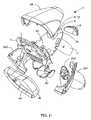
- FIG. 1Iis a first perspective exploded view of the hand-supportable Digital Imaging-Based Bar Code Symbol Reading Device of the first illustrative embodiment of the present invention
- FIG. 1Jis a second perspective exploded view of the hand-supportable Digital Imaging-Based Bar Code Symbol Reading Device of the first illustrative embodiment of the present invention
- FIG. 1Kis a third perspective exploded view of the hand-supportable Digital Imaging-Based Bar Code Symbol Reading Device of the first illustrative embodiment of the present invention
- FIG. 2 A 1is a schematic block diagram representative of a system design for the hand-supportable Digital Imaging-Based Bar Code Symbol Reading Device illustrated in FIGS. 1A through 1L , wherein the system design is shown comprising (1) a Multi-Mode Area-Type Image Formation and Detection (i.e.
- CameraSubsystem having image formation (camera) optics for producing a field of view (FOV) upon an object to be imaged and a CMOS or like area-type image sensing array for detecting imaged light reflected off the object during illumination operations in either (i) a narrow-area image capture mode in which a few central rows of pixels on the image sensing array are enabled, or (ii) a wide-area image capture mode in which all rows of the image sensing array are enabled, (2) a Multi-Mode LED-Based Illumination Subsystem for producing narrow and wide area fields of narrow-band illumination within the FOV of the Image Formation And Detection Subsystem during narrow and wide area modes of image capture, respectively, so that only light transmitted from the Multi-Mode Illumination Subsystem and reflected from the illuminated object and transmitted through a narrow-band transmission-type optical filter realized within the hand-supportable housing (i.e.
- an IR-based object presence and range detection subsystemfor producing an IR-based object detection field within the FOV of the Image Formation and Detection Subsystem
- an Automatic Light Exposure Measurement and Illumination Control Subsystemfor controlling the operation of the LED-Based Multi-Mode Illumination Subsystem
- an Image Capturing and Buffering Subsystemfor capturing and buffering 2-D images detected by the Image Formation and Detection Subsystem
- a Multimode Image-Processing Based Bar Code Symbol Reading Subsystemfor processing images captured and buffered by the Image Capturing and Buffering Subsystem and reading 1D and 2D bar code symbols represented
- an Input/Output Subsystemfor outputting processed image data and the like to an external host system or other information receiving or responding device, in which each said subsystem component is integrated about
- FIG. 2 A 2is a schematic block representation of the multi-Mode Image-Processing Based Bar Code Symbol Reading Subsystem, realized using the three-tier computing platform illustrated in FIG. 2B ;
- FIG. 2Bis schematic diagram representative of a system implementation for the hand-supportable Digital Imaging-Based Bar Code Symbol Reading Device illustrated in FIGS. 1 A through 2 A 2 , wherein the system implementation is shown comprising (1) an illumination board 33 carrying components realizing electronic functions performed by the Multi-Mode LED-Based Illumination Subsystem and the Automatic Light Exposure Measurement And Illumination Control Subsystem, (2) a CMOS camera board carrying a high resolution (1280 ⁇ 1024 8-bit 6 micron pixel size) CMOS image sensor array running at 25 Mhz master clock, at 7 frames/second at 1280*1024 resolution with randomly accessible region of interest (ROI) window capabilities, realizing electronic functions performed by the multi-mode area-type Image Formation and Detection Subsystem, (3) a CPU board (i.e.
- computing platformincluding (i) an Intel Sabinal 32-Bit Microprocessor PXA210 running at 200 Mhz 1.0 core voltage with a 16 bit 100 Mhz external bus speed, (ii) an expandable (e.g. 8+megabyte) Intel J3 Asynchronous 16-bit Flash memory, (iii) an 16 Megabytes of 100 MHz SDRAM, (iv) an Xilinx Spartan II FPGA FIFO 39 running at 50 Mhz clock frequency and 60 MB/Sec data rate, configured to control the camera timings and drive an image acquisition process, (v) a multimedia card socket, for realizing the other subsystems of the system, (vi) a power management module for the MCU adjustable by the system bus, and (vii) a pair of UARTs (one for an IRDA port and one for a JTAG port), (4) an interface board for realizing the functions performed by the I/O subsystem, and (5) an IR-based object presence and range detection circuit for realizing the IR-based Object
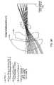
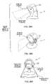
- FIG. 3Ais a schematic representation showing the spatial relationships between the near and far and narrow and wide area fields of narrow-band illumination within the FOV of the Multi-Mode Image Formation and Detection Subsystem during narrow and wide area image capture modes of operation;
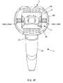
- FIG. 3Bis a perspective partially cut-away view of the hand-supportable Digital Imaging-Based Bar Code Symbol Reading Device of the first illustrative embodiment, showing the LED-Based Multi-Mode Illumination Subsystem transmitting visible narrow-band illumination through its narrow-band transmission-type optical filter system and illuminating an object with such narrow-band illumination, and also showing the image formation optics, including the low pass filter before the image sensing array, for collecting and focusing light rays reflected from the illuminated object, so that an image of the object is formed and detected using only the optical components of light contained within the narrow-band of illumination, while all other components of ambient light are substantially rejected before image detection at the image sensing array;
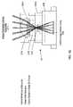
- FIG. 3Cis a schematic representation showing the geometrical layout of the optical components used within the hand-supportable Digital Imaging-Based Bar Code Reading Device of the first illustrative embodiment, wherein the red-wavelength reflecting high-pass lens element is positioned at the imaging window of the device before the image formation lens elements, white the low-pass filter is disposed before the image sensor of between the image formation elements, so as to image the object at the image sensing array using only optical components within the narrow-band of illumination, while rejecting all other components of ambient light;
- FIG. 3Eis a schematic representation of the lens holding assembly employed in the image formation optical subsystem of the hand-supportable Digital Imaging-Based Bar Code Reading Device of the first illustrative embodiment, showing a two-piece barrel structure which holds the lens elements, and a base structure which holds the image sensing array, wherein the assembly is configured so that the barrel structure slides within the base structure so as to focus the assembly;
- FIG. 3 F 1is a first schematic representation showing, from a side view, the physical position of the LEDs used in the Multi-Mode Illumination Subsystem, in relation to the image formation lens assembly, the image sensing array employed therein (e.g. a Motorola MCM20027 or National Semiconductor LM9638 CMOS 2-D image sensing array having a 1280 ⁇ 1024 pixel resolution (1 ⁇ 2′′ format), 6 micron pixel size, 13.5 Mhz clock rate, with randomly accessible region of interest (ROI) window capabilities);
- the image sensing array employed thereine.g. a Motorola MCM20027 or National Semiconductor LM9638 CMOS 2-D image sensing array having a 1280 ⁇ 1024 pixel resolution (1 ⁇ 2′′ format), 6 micron pixel size, 13.5 Mhz clock rate, with randomly accessible region of interest (ROI) window capabilities
- FIG. 3 F 2is a second schematic representation showing, from an axial view, the physical layout of the LEDs used in the Multi-Mode Illumination Subsystem of the Digital Imaging-Based Bar Code Reading Device, shown in relation to the image formation lens assembly, and the image sensing array employed therein;
- FIG. 3Gis a flow chart describing the steps involved in determining the Depth of Field (DOF) of the image formation optics assembly employed in the bar code reading system of the present invention
- FIG. 4Ais a schematic representation of the Depth of Field Chart used in the design of the image formation optics in the Digital Imaging-Based Bar Code Reading Device, wherein image formation lens resolution characteristics are plotted against the pixel limits of the image sensing array;
- FIG. 4Bis graphical chart illustrating the performance of the image formation optics of the Digital Imaging-Based Bar Code Reading Device of the present invention, plotting object distance (centimeters) against MTF values of image formation optics;
- FIG. 4Cis a schematic representation illustrating the Depth of Field of the image formation optics of the Digital Imaging-Based Bar Code Reading Device of the present invention, measured in millimeters, and showing the narrowest bar code element dimension that can be measured over particular regions within its Depth of Field;
- FIG. 4Dshows a DOF chart that plots the resolution of the image formation optics, indicating only the optical performance of the subsystem
- FIG. 4Egraphically illustrates how to read off the DOF for a certain mil size code, considering only the optical performance of the image formation optics of the Image Formation and Detection Subsystem;
- FIG. 4Fshows the 1.4 and 1.6 pixel sampling limits plotted on the same axes as the optical performance curve for a fixed focal length reader (as they are functions of object distance);
- FIG. 4Ggraphically illustrates how to determine the composite DOF curve of the Image Formation and Detection Subsystem, considering optical performance and sampling limit together, for the 1.6 pixel case;
- FIG. 4Hgraphically illustrates how to read off the DOF for a certain mil size code, considering optical performance and sampling limit together, for the 1.6 pixel case;
- FIG. 4 I 1 through 4 I 3taken together, show an exemplary computer program written in ZPL (Zemax Programming Language) and capable of generating the composite DOF chart;
- FIG. 5 A 1is a schematic representation specifying the range of narrow-area illumination, near-field wide-area illumination, and far-field wide-area illumination produced from the LED-Based Multi-Mode Illumination Subsystem employed in the hand-supportable Digital Imaging-Based Bar Code Reading Device of the present invention;
- FIG. 5 A 2is a table specifying the geometrical properties and characteristics of each illumination mode supported by the LED-Based Multi-Mode Illumination Subsystem employed in the hand-supportable Digital Imaging-Based Bar Code Reading Device of the present invention
- FIG. 5Bis a schematic representation illustrating the physical arrangement of LED light sources associated with the narrow-area illumination array and the near-field and far-field wide-area illumination arrays employed in the Digital Imaging-Based Bar Code Reading Device of the present invention, wherein the LEDs in the far-field wide-area illuminating arrays are located behind spherical lenses, the LEDs in the narrow-area illuminating array are disposed behind cylindrical lenses, and the LEDs in the near-field wide-area illuminating array are unlensed in the first illustrative embodiment of the Digital Imaging-Based Bar Code Reading Device;
- FIG. 5 C 1is graphical representation showing the Lambertian emittance versus wavelength characteristics of the LEDs used to implement the narrow-area illumination array in the Multi-Mode Illumination Subsystem of the present invention
- FIG. 5 C 2is graphical representation showing the Lambertian emittance versus polar angle characteristics of the LEDs used to implement the narrow-area illumination array in the Multi-Mode Illumination Subsystem of the present invention
- FIG. 5 C 3is schematic representation of the cylindrical lenses used before the LEDs in the narrow-area (linear) illumination arrays in the Digital Imaging-Based Bar Code Reading Device of the present invention, wherein the first surface of the cylindrical lens is curved vertically to create a narrow-area (i.e. linear) illumination pattern, and the second surface of the cylindrical lens is curved horizontally to control the height of the of the narrow-area illumination pattern to produce a narrow-area (i.e. linear) illumination field;
- FIG. 5 C 4is a schematic representation of the layout of the pairs of LEDs and two cylindrical lenses used to implement the narrow-area (linear) illumination array employed in the Digital Imaging-Based Bar Code Reading Device of the present invention
- FIG. 5 C 5is a set of six illumination profiles for the narrow-area (linear) illumination fields produced by the narrow-area (linear) illumination array employed in the Digital Imaging-Based Bar Code Reading Device of the illustrative embodiment, taken at 30, 40, 50, 80, 120, and 220 millimeters along the field away from the imaging window (i.e. working distance) of the Digital Imaging-Based Bar Code Reading Device, illustrating that the spatial intensity of the narrow-area illumination field begins to become substantially uniform at about 80 millimeters;
- FIG. 5 D 1is graphical representation showing the Lambertian emittance versus wavelength characteristics of the LEDs used to implement the wide area illumination arrays employed in the Digital Imaging-Based Bar Code Reading Device of the present invention
- FIG. 5 D 2is graphical representation showing the Lambertian emittance versus polar angle characteristics of the LEDs used to implement the far-field and near-field wide-area illumination arrays employed in the Digital Imaging-Based Bar Code Reading Device of the present invention
- FIG. 5 D 3is schematic representation of the piano-convex lenses used before the LEDs in the far-field wide-area illumination arrays in the illumination subsystem of the present invention
- FIG. 5 D 4is a schematic representation of the layout of LEDs and piano-convex lenses used to implement the far and narrow wide-area illumination array employed in the Digital Imaging-Based Bar Code Reading Device of the present invention, wherein the illumination beam produced therefrom is aimed by positioning the lenses at angles before the LEDs in the near-field (and far-field) wide-area illumination arrays employed therein;
- FIG. 5 D 5is a set of six illumination profiles for the near-field wide-area illumination fields produced by the near-field wide-area illumination arrays employed in the Digital Imaging-Based Bar Code Reading Device of the illustrative embodiment, taken at 10, 20, 30, 40, 60, and 100 millimeters along the field away from the imaging window (i.e. working distance) of the Digital Imaging-Based Bar Code Reading Device, illustrating that the spatial intensity of the near-field wide-area illumination field begins to become substantially uniform at about 40 millimeters;
- FIG. 5 D 6is a set of three illumination profiles for the far-field wide-area illumination fields produced by the far-field wide-area illumination arrays employed in the Digital Imaging-Based Bar Code Reading Device of the illustrative embodiment, taken at 100, 150 and 220 millimeters along the field away from the imaging window (i.e. working distance) of the Digital Imaging-Based Bar Code Reading Device, illustrating that the spatial intensity of the far-field wide-area illumination field begins to become substantially uniform at about 100 millimeters;
- FIG. 5 D 7is a table illustrating a preferred method of calculating the pixel intensity value for the center of the far-field wide-area illumination field produced from the Multi-Mode Illumination Subsystem employed in the Digital Imaging-Based Bar Code Reading Device of the present invention, showing a significant signal strength (greater than 80 DN);
- FIG. 6 A 1is a schematic representation showing the red-wavelength reflecting (high-pass) imaging window integrated within the hand-supportable housing of the Digital Imaging-Based Bar Code Reading Device, and the low-pass optical filter disposed before its CMOS image sensing array therewithin, cooperate to form a narrow-band optical filter subsystem for transmitting substantially only the very narrow band of wavelengths (e.g. 620–700 nanometers) of visible illumination produced from the Multi-Mode Illumination Subsystem employed in the Digital Imaging-Based Bar Code Reading Device, and rejecting all other optical wavelengths outside this narrow optical band however generated (i.e. ambient light sources);
- a narrow-band optical filter subsystemfor transmitting substantially only the very narrow band of wavelengths (e.g. 620–700 nanometers) of visible illumination produced from the Multi-Mode Illumination Subsystem employed in the Digital Imaging-Based Bar Code Reading Device, and rejecting all other optical wavelengths outside this narrow optical band however generated (i.e. ambient light sources);
- FIG. 6 A 2is schematic representation of transmission characteristics (energy versus wavelength) associated with the low-pass optical filter element disposed after the red-wavelength reflecting high-pass imaging window within the hand-supportable housing of the Digital Imaging-Based Bar Code Reading Device, but before its CMOS image sensing array, showing that optical wavelengths below 620 nanometers are transmitted and wavelengths above 620 nm are substantially blocked (e.g. absorbed or reflected);
- FIG. 6 A 3is schematic representation of transmission characteristics (energy versus wavelength) associated with the red-wavelength reflecting high-pass imaging window integrated within the hand-supportable housing of the Digital Imaging-Based Bar Code Reading Device of the present invention, showing that optical wavelengths above 700 nanometers are transmitted and wavelengths below 700 nm are substantially blocked (e.g. absorbed or reflected);
- FIG. 6 A 4is a schematic representation of the transmission characteristics of the narrow-based spectral filter subsystem integrated within the hand-supportable Imaging-Based Bar Code Symbol Reading Device of the present invention, plotted against the spectral characteristics of the LED-emissions produced from the Multi-Mode Illumination Subsystem of the illustrative embodiment of the present invention;
- FIG. 7Ais a schematic representation showing the geometrical layout of the spherical/parabolic light reflecting/collecting mirror and photodiode associated with the Automatic Light Exposure Measurement and Illumination Control Subsystem, and arranged within the hand-supportable Digital Imaging-Based Bar Code Symbol Reading Device of the illustrative embodiment, wherein incident illumination is collected from a selected portion of the center of the FOV of the system using a spherical light collecting mirror, and then focused upon a photodiode for detection of the intensity of reflected illumination and subsequent processing by the Automatic Light Exposure Measurement and Illumination Control Subsystem, so as to then control the illumination produced by the LED-based Multi-Mode Illumination Subsystem employed in the Digital Imaging-Based Bar Code Reading Device of the present invention;
- FIG. 7Bis a schematic diagram of the Automatic Light Exposure Measurement and Illumination Control Subsystem employed in the hand-supportable Digital Imaging-Based Bar Code Symbol Reading Device of the present invention, wherein illumination is collected from the center of the FOV of the system and automatically detected so as to generate a control signal for driving, at the proper intensity, the narrow-area illumination array as well as the far-field and narrow-field wide-area illumination arrays of the Multi-Mode Illumination Subsystem, so that the CMOS image sensing array produces digital images of illuminated objects of sufficient brightness;
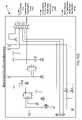
- FIGS. 7 C 1 and 7 C 2set forth a schematic diagram of a hybrid analog/digital circuit designed to implement the Automatic Light Exposure Measurement and Illumination Control Subsystem of FIG. 7B employed in the hand-supportable Digital Imaging-Based Bar Code Symbol Reading Device of the present invention
- FIG. 7Dis a schematic diagram showing that, in accordance with the principles of the present invention, the CMOS image sensing array employed in the Digital Imaging-Based Bar Code Reading Device of the illustrative embodiment, once activated by the System Control Subsystem (or directly by the trigger switch), and when all rows in the image sensing array are in a state of integration operation, automatically activates the Automatic Light Exposure Measurement and Illumination Control Subsystem which, in response thereto, automatically activates the LED illumination driver circuitry to automatically drive the appropriate LED illumination arrays associated with the Multi-Mode Illumination Subsystem in a precise manner and globally expose the entire CMOS image detection array with narrowly tuned LED-based illumination when all of its rows of pixels are in a state of integration, and thus have a common integration time, thereby capturing high quality images independent of the relative motion between the bar code reader and the object;
- FIGS. 7 E 1 and 7 E 2taken together, set forth a flow chart describing the steps involved in carrying out the global exposure control method of the present invention, within the Digital Imaging-Based Bar Code Reading Device of the illustrative embodiment;
- FIG. 8is a schematic block diagram of the IR-based automatic Object Presence and Range Detection Subsystem employed in the hand-supportable Digital Imaging-Based Bar Code Symbol Reading Device of the present invention, wherein a first range indication control signal is generated upon detection of an object within the near-field region of the Multi-Mode Illumination Subsystem, and wherein a second range indication control signal is generated upon detection of an object within the far-field region of the Multi-Mode Illumination Subsystem;
- FIG. 9is a schematic representation of the hand-supportable Digital Imaging-Based Bar Code Symbol Reading Device of the present invention, showing that its CMOS image sensing array is operably connected to its microprocessor through a FIFO (realized by way of a FPGA) and a system bus, and that its SDRAM is also operably connected to the microprocessor by way of the system bus, enabling the mapping of pixel data captured by the imaging array into the SDRAM under the control of the direct memory access (DMA) module within the microprocessor;
- DMAdirect memory access
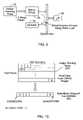
- FIG. 10is a schematic representation showing how the bytes of pixel data captured by the CMOS imaging array within the hand-supportable Digital Imaging-Based Bar Code Symbol Reading Device of the present invention, are mapped into the addressable memory storage locations of its SDRAM during each image capture cycle carried out within the device;
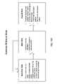
- FIG. 11is a schematic representation showing the software modules associated with the three-tier software architecture of the hand-supportable Digital Imaging-Based Bar Code Symbol Reading Device of the present invention, namely: the Main Task module, the CodeGate Task module, the Metroset Task module, the Application Events Manager module, the User Commands Table module, and the Command Handler module residing with the Application layer of the software architecture; the Tasks Manager module, the Events Dispatcher module, the Input/Output Manager module, the User Commands Manager module, the Timer Subsystem module, the Input/Output Subsystem module and the Memory Control Subsystem module residing with the System Core (SCORE) layer of the software architecture; and the Linux Kernal module, the Linux File System module, and Device Drivers modules residing within the Linux Operating System (OS) layer of the software architecture;
- the Main Task modulethe CodeGate Task module, the Metroset Task module, the Application Events Manager module, the User Commands Table module, and the Command Handler module residing with the Application layer of the software architecture
- FIG. 12Ais a schematic representation of the Events Dispatcher software module which provides a means of signaling and delivering events to the Application Events Manager, including the starting of a new task, stopping a currently running task, doing something, or doing nothing and ignoring the event;
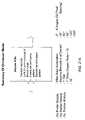
- FIG. 12Bis a Table listing examples of System-Defined Events which can occur and be dispatched within the hand-supportable Digital Imaging-Based Bar Code Symbol Reading Device of the present invention, namely: SCORE_EVENT_POWER_UP which signals the completion of system start-up and involves no parameters; _SCORE_EVENT_TIMEOUT which signals the timeout of the logical timer, and involves the parameter “pointer to timer id”; SCORE_EVENT_UNEXPECTED_INPUT which signals that the unexpected input data is available and involves the parameter “pointer to connection id”; SCORE_EVENT_TRIG_ON which signals that the user pulled the trigger switch and involves no parameters; SCORE_EVENT_TRIG_OFF which signals that the user released the trigger switch and involves no parameters; SCORE_EVENT_OBJECT_DETECT_ON which signals that the object is positioned under the bar code reader and involves no parameters; SCORE_EVENT_OBJECT_DETECT_OFF which signals that the object is removed from the field
- FIG. 12Cis a schematic representation of the Tasks Manager software module which provides a means for executing and stopping application specific tasks (i.e. threads);
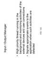
- FIG. 12Dis a schematic representation of the Input/Output Manager software module (i.e Input/Output Subsystem), which runs in the background and monitors activities of external such activities are detected;
- Input/Output Manager software modulei.e Input/Output Subsystem
- FIGS. 12 E 1 and 12 E 2set forth a schematic representation of the Input/Output Subsystem software module which provides a means for creating and deleting input/output connections, and communicating with external systems and devices;
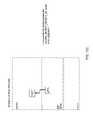
- FIGS. 12 F 1 and 12 F 2set forth a schematic representation of the Timer Subsystem which provides a means for creating, deleting, and utilizing logical timers;
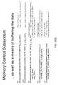
- FIGS. 12 G 1 and 12 G 2set forth a schematic representation of the Memory Control Subsystem which provides an interface for managing the thread-level dynamic memory with the device, fully compatible with standard dynamic memory management functions, as well as a means for buffering collected data;
- FIG. 12His a schematic representation of the User Commands Manager which provides a standard way of entering user commands, and executing application modules responsible for handling the same;
- FIG. 12Iis a schematic representation of the Device Driver software modules, which includes trigger switch drivers for establishing a software connection with the hardware-based manually-actuated trigger switch employed on the Digital Imaging-Based Bar Code Reading Device, an image acquisition driver for implementing image acquisition functionality aboard the Digital Imaging-Based Bar Code Reading Device, and an IR driver for implementing object detection functionality aboard the Imaging-Based Bar Code Symbol Reading Device;
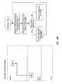
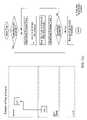
- FIG. 13Ais an exemplary flow chart representation showing how when the user points the bar code reader towards a bar code symbol, the IR device drivers detect that object within the field, and then wakes up the Input/Output Manager software module at the System Core Layer,
- FIG. 13Bis an exemplary flow chart representation showing how upon detecting an object, the Input/Output Manager posts the SCORE_OBJECT_DETECT_ON event to the Events Dispatcher software module;
- FIG. 13Cis an exemplary flow chart representation showing how, in response to detecting an object, the Events Dispatcher software module passes the SCORE_OBJECT_DETECT_ON event to the Application Layer;
- FIG. 13Dis an exemplary flow chart representation showing how upon receiving the SCORE_OBJECT_DETECT_ON event at the Application Layer, the Application Events Manager executes an event handling routine which activates the narrow-area illumination array associated with the Multi-Mode Illumination Subsystem, and executes the CodeGate Task described in FIG. 13E ;
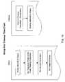
- FIG. 13Eis an exemplary flow chart representation showing how what operations are carried out when the CodeGate Task is executed within the Application Layer;
- FIG. 13Fis an exemplary flow chart representation showing how, when the user pulls the trigger switch on the bar code reader while the Code Task is executing, the trigger device driver wakes up the Input/Output Manager at the System Core Layer;
- FIG. 13Gis an exemplary flow chart representation showing how, in response to waking up, the Input/Output Manager posts the SCORE_TRIGGER_ON event to the Events Dispatcher;
- FIG. 13His an exemplary flow chart representation showing how the Events Dispatcher passes on the SCORE_TRIGGER_ON event to the Application Events Manager at the Application Layer;
- FIG. 13Iis an exemplary flow chart representation showing how the Application Events Manager responds to the SCORE_TRIGGER_ON event by invoking a handling routine within the Task Manager at the System Core Layer which deactivates the narrow-area illumination array associated with the Multi-Mode Illumination Subsystem, cancels the CodeGate Task, and executes the Main Task;
- FIG. 13Jis an exemplary flow chart representation showing what operations are carried out when the Main Task is executed within the Application Layer;
- FIG. 13Kis an exemplary flow chart representation showing what operations are carried out when the Data Output Procedure, called in the Main Task, is executed within the Input/Output Subsystem software module in the Application Layer;
- FIG. 13Lis an exemplary flow chart representation showing decoded symbol character data being sent from the Input/Output Subsystem to the Device Drivers within the Linux OS Layer of the system;
- FIG. 13Mis a flow chart describing a novel method of generating wide-area illumination, for use during the Main Task routine so as to illuminate objects with a wide-area illumination field in a manner, which substantially reduces specular-type reflection at the CMOS image sensing array in the Digital Imaging-Based Bar Code Reading Device of the present invention
- FIG. 14is a table listing various bar code symbologies supported by the Multi-Mode Bar Code Symbol Reading Subsystem module employed within the hand-supportable Digital Imaging-Based Bar Code Symbol Reading Device of the present invention
- FIG. 15is a table listing the four primary modes in which the Multi-Mode Bar Code Symbol Reading Subsystem module can be programmed to operate, namely: the Automatic Mode wherein the Multi-Mode Bar Code Symbol Reading Subsystem is configured to automatically process a captured frame of digital image data so as to search for one or more bar codes represented therein in an incremental manner, and to continue searching until the entire image is processed; the Manual Mode wherein the Multi-Mode Bar Code Symbol Reading Subsystem is configured to automatically process a captured frame of digital image data, starting from the center or sweep spot of the image at which the user would have aimed the bar code reader, so as to search for (i.e.
- the Multi-Mode Bar Code Symbol Reading Subsystemis configured to automatically process a specified “region of interest” (ROI) in a captured frame of digital image data so as to search for one or more bar codes represented therein, in response to coordinate data specifying the location of the bar code within the field of view of the multi-mode image formation and detection system; the NoFinder Mode wherein the Multi-Mode Bar Code Symbol Reading Subsystem is configured to automatically process a captured narrow-area (linear) frame of digital image data, without feature extraction and marking operations used in the Automatic and Manual Modes, so as read one or more bar code symbols represented therein; and the Omniscan Mode, wherein the Multi-Mode Bar Code Symbol Reading Subsystem is configured to automatically process a captured frame of digital image data along any one or
- FIG. 16is is a exemplary flow chart representation showing the steps involved in setting up and cleaning up the software sub-Application entitled “Multi-Mode Image-Processing Based Bar Code Symbol Reading Subsystem”, once called from either (i) the CodeGate Task software module at the Block entitled READ BAR CODE(S) IN CAPTURED NARROW-AREA IMAGE indicated in FIG. 13E , or (ii) the Main Task software module at the Block entitled “READ BAR CODE(S) IN CAPTURED WIDE-AREA IMAGE” indicated in FIG. 13J ;
- FIG. 17Ais a summary of the steps involved in the decode process carrying out by the Multi-Mode Bar Code Symbol Reading Subsystem of the present invention during its Automatic Mode of operation, wherein (I) the first stage of processing involves searching for (i.e. finding) regions of interest (ROIs) by processing a low resolution image of a captured frame of high-resolution image data, partitioning the low-resolution image into N ⁇ N blocks, and creating a feature vector for each block using spatial-derivative based image processing techniques, (2) the second stage of processing involves marking ROIs by examining the feature vectors for regions of high-modulation, calculating bar code orientation and marking the four corners of a bar code as a ROI, and (3) the third stage of processing involves reading any bar code symbols represented within the ROI by traversing the bar code and updating the feature vectors, examining the zero-crossings of filtered images, creating bar and space patterns, and decoding the bar and space patterns using conventional decoding algorithms;
- ROIsregions of interest
- FIG. 17Bis an exemplary flow chart representation of the steps involved in the image-processing method carried out by the Multi-Mode Bar Code Symbol Reading Subsystem during its Automatic Mode of operation;
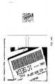
- FIG. 18Ais a graphical representation illustrating the generation of a low-resolution image of a package label from an original high-resolution image thereof during the first finding stage of processing within the Multi-Mode Bar Code Symbol Reading Subsystem configured in its Automatic Mode of operation;
- FIG. 18Bis a graphical representation illustrating the partitioning of the low-resolution image of the package label, the calculation of feature vectors using the same, and the analysis of these feature vectors for parallel lines, during the first finding stage of processing within the Multi-Mode Bar Code Symbol Reading Subsystem during its Automatic Mode of operation;
- FIG. 18Cis a graphical representation showing that the calculation of feature vectors within each block of low-resolution image data, during the second marking stage of processing within the Multi-Mode Bar Code Symbol Reading Subsystem, can involve the use of gradient vectors, edge density measures, the number of parallel edge vectors, centroids of edgels, intensity variance, and the histogram of intensities captured from the low-resolution image;
- FIG. 18Dis a graphical representation of the examination of feature vectors looking for high edge density, large number of parallel edge vectors and large intensity variance, during the second marking stage of processing within the Multi-Mode Bar Code Symbol Reading Subsystem during its Automatic Mode of operation;
- FIGS. 18E and 18Fset forth graphical representations of calculating bar code orientation during the second marking stage of processing within the Multi-Mode Bar Code Symbol Reading Subsystem operating in its Automatic Mode, wherein each feature vector block, the bar code is traversed (i.e. sliced) at different angles, the slices are matched with each other based on “least mean square error”, and the correct orientation is determined to be that angle which matches the mean square error sense through every slice of the bar code symbol represented within the captured image;
- FIG. 18Fis a graphical representation of calculating bar code orientation, during the second marking stage of processing within the Multi-Mode Bar Code Symbol Reading Subsystem operating in its Automatic Mode;
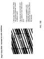
- FIG. 18Gis a graphical representation of the marking of the four corners of the detected bar code symbol during the second marking stage of processing within the Multi-Mode Bar Code Symbol Reading Subsystem operating in its Automatic Mode, wherein such marking operations are performed on the full high-resolution image of the parcel, the bar code is traversed in either direction starting from the center of the block, the extent of modulation is detected using the intensity variance, and the x,y coordinates (pixels) of the four corners of the bar code are detected starting from 1 and 2 and moving perpendicular to the bar code orientation, and define the ROI by the detected four corners of the bar code symbol within the high-resolution image;
- FIG. 18His a graphical representation of updating the feature vectors during the third stage of processing within the Multi-Mode Bar Code Symbol Reading Subsystem operating in its Automatic Mode, wherein the histogram component of the feature vector Fv is updated while traversing the bar code symbol, the estimate of the black-to-white transition is calculated, and an estimate of narrow and wide elements of the bar code symbol are calculated;
- FIG. 18Iis a graphical representation of the search for zero crossings during the third stage of processing within the Multi-Mode Bar Code Symbol Reading Subsystem operating in its Automatic Mode, wherein the high-resolution bar code image is median filtered in a direction perpendicular to bar code orientation, the second derivative zero crossings define edge crossings, the zero-crossing data is used only for detecting edge transitions, and the black/white transition estimates are used to put upper and lower bounds on the grey levels of the bars and spaces of the bar code symbol represented within the captured image;
- FIG. 18Jis a graphical representation of creating bar and space pattern during the third stage of processing within the Multi-Mode Bar Code Symbol Reading Subsystem operating in its Automatic Mode, wherein the edge transition is modeled as a ramp function, the edge transition is assumed to be 1 pixel wide, the edge transition location is determined at the subpixel level, and the bar and space counts are gathered using edge transition data;
- FIG. 18Kis a graphical representation of the decode bar and space pattern during the third stage of processing within the Multi-Mode Bar Code Symbol Reading Subsystem operating in its Automatic Mode, wherein the bar and space data is framed with borders, and the bar and space data is decoded using existing laser scanning bar code decoding algorithms;
- FIG. 19Ais a summary of the steps involved in the image-processing method carried out by the Multi-Mode Bar Code Symbol Reading Subsystem during its Manual Mode of operation, wherein (1) the first stage of processing involves searching for (i.e. finding) regions of interest (ROIs) by processing a low resolution image of a captured frame of high-resolution image data, partitioning the low-resolution image into N ⁇ N blocks, and creating a feature vector for the middle block using spatial-derivative based image processing techniques, (2) the second stage of processing involves marking ROIs by examining the feature vectors for regions of high-modulation and returning to the first stage to create feature vectors for other blocks surrounding the middle block (in a helical manner), calculating bar code orientation and marking the four corners of a bar code as a ROI, and (3) the third stage of processing involves reading any bar code symbols represented within the ROI by traversing the bar code and updating the feature vectors, examining the zero-crossings of filtered images, creating bar and space patterns, and decoding the bar and space patterns using conventional de
- FIG. 19Bis an exemplary flow chart representation of the steps involved in the image-processing method carrying out by the Multi-Mode Bar Code Symbol Reading Subsystem during its Manual Mode of operation;
- FIG. 20Ais a summary of the steps involved in the image processing method carried out by the Multi-Mode Bar Code Symbol Reading Subsystem during its NoFinder Mode of operation, wherein the Decoder Module does not employ bar code element finding or marking techniques (i.e. Finder Module and Marker Module) and directly processes a narrow-area portion of a captured high-resolution image, starting from the middle thereof, examines the zero-crossings of the filtered image, creates bar and space patterns therefrom, and then decodes the bar and space patterns using conventional decoding algorithms;
- bar code element finding or marking techniquesi.e. Finder Module and Marker Module
- FIG. 20Bis an exemplary flow chart representation of the steps involved in the image-processing method carried out by the Multi-Mode Bar Code Symbol Reading Subsystem during its NoFinder Mode of operation;
- FIG. 21Ais a summary of the steps involved in the image-processing method carried out by the Multi-Mode Bar Code Symbol Reading Subsystem during its OmniScan Mode of operation, wherein the Decoder Module does not employ bar code element finding or marking techniques (i.e. Finder Module and Marker Module), assumes the imaged bar code symbol resides at the center of the captured wide-area high-resolution image with about a 1:1 aspect ratio, and directly processes the high-resolution image along a set of parallel spaced-apart (e.g.
- virtual scan linesexamines the zero-crossings along the virtual scan lines, creates bar and space patterns therefrom, and then decodes the bar and space patterns, with the option of reprocessing the high-resolution image along a different set of parallel spaced-apart virtual scan lines oriented at a different angle from the previously processed set of virtual scan lines (e.g. 0, 30, 60, 90, 120 or 150 degrees);
- FIG. 21Bis an exemplary flow chart representation of the steps involved in the image-processing method carried out by the Multi-Mode Bar Code Symbol Reading Subsystem during its OmniScan Mode of operation;
- FIG. 22Ais a summary of the steps involved in the image-processing based bar code reading method carried out by the Multi-Mode Bar Code Symbol Reading Subsystem of the present invention during its “ROI-Specific” Mode of operation, designed for use in combination with the Omniscan Mode of operation, wherein (1) the first stage of processing involves receiving region of interest (ROI) coordinates (x1, x2) obtained during the Omniscan Mode of operation (after the occurrence of a failure to decode), re-partitioning the captured low-resolution image (from the Omniscan Mode) into N ⁇ N blocks, and creating a feature vector for the ROI-specified block(s) using spatial-derivative based image processing techniques, (2) the second stage of processing involves marking additional ROIs by examining the feature vectors for regions of high-modulation and returning to the first stage to create feature vectors for other blocks surrounding the middle block (in a helical manner), calculating bar code orientation and marking the four corners of a bar code as a ROI, and (3) the third stage of processing involves reading any
- FIG. 22Bis an exemplary flow chart representation of the steps involved in the image-processing method carried out by the Multi-Mode Bar Code Symbol Reading Subsystem of the present invention during its ROI-specific Mode of operation;
- FIG. 23is a specification of Multi-Mode Bar Code Symbol Reading Subsystem operated during its first multi-read (Omniscan/ROI-Specific) mode of operation;
- FIG. 24is a specification of Multi-Mode Bar Code Symbol Reading Subsystem operated during its second multi-read (No-Finder/ROI-Specific) mode of operation;
- FIG. 25is a specification of Multi-Mode Bar Code Symbol Reading Subsystem operated during its third multi-read (No-Finder/Omniscan/ROI-Specific) mode of operation;
- FIGS. 26A and 26Btaken together, provide a table listing the primary Programmable Modes of Bar Code Reading Operation within the hand-supportable Digital Imaging-Based Bar Code Symbol Reading Device of the present invention, namely: Programmed Mode of System Operation No. 1—Manually-Triggered Single-Attempt 1D Single-Read Mode Employing the No-Finder Mode of the Multi-Mode Bar Code Reading Subsystem; Programmed Mode Of System Operation No. 2—Manually-Triggered Multiple-Attempt 1D Single-Read Mode Employing the No-Finder Mode of the Multi-Mode Bar Code Reading Subsystem; Programmed Mode Of System Operation No.
- FIG. 27Ais a schematic representation specifying the four modes of illumination produced from the Multi-Mode Illumination Subsystem employed in the second illustrative embodiment of the Digital Imaging-Based Bar Code Symbol Reader of the present invention, which supports both near and far fields of narrow-area illumination generated during the narrow-area image capture mode of its Multi-Mode Image Formation and Detection Subsystem;
- FIG. 27Bis a schematic representation specifying how the cylindrical beam shaping optics employed within near-field and far-field narrow-area illumination arrays can be easily tailored to generate near and far narrow-area illumination fields having geometrical characteristics that enables (i) simple reading of extended-length bar code symbols within the far-field region of the FOV of the system, and also (ii) simple reading of bar code menus with a great degree of control within the near-field region of the FOV, preferably during a “Semi-Automatic-Triggered” programmed mode of system operation;
- FIG. 28is a schematic representation illustrating the physical arrangement of LEDs and light focusing lenses associated with the near and far field narrow-area and wide-area illumination arrays employed in the Digital Imaging-Based Bar Code Symbol Reading Device according to the second illustrative embodiment of the present invention
- FIG. 29Ais a first perspective view of a second illustrative embodiment of the portable POS Digital Imaging-Based Bar Code Symbol Reading Device of the present invention, shown having a hand-supportable housing of a different form factor than that of the first illustrative embodiment, and configured for use in its hands-free/presentation mode of operation, supporting primarily wide-area image capture;
- FIG. 29Bis a second perspective view of the second illustrative embodiment of the portable POS Digital Imaging-Based Bar Code Reading Device of the present invention, shown configured and operated in its hands-free/presentation mode of operation, supporting primarily wide-area image capture;
- FIG. 29Cis a third perspective view of the second illustrative embodiment of the portable Digital Imaging-Based Bar Code Reading Device of the present invention, showing configured and operated in a hands-on type mode, supporting both narrow and wide area modes of image capture;
- FIG. 30is a perspective view of a third illustrative embodiment of the Digital Imaging-Based Bar Code Symbol Reading Device of the present invention, realized in the form of a Multi-Mode Image Capture And Processing Engine that can be readily integrated into various kinds of information collection and processing systems, including wireless portable data terminals (PDTs), reverse-vending machines, retail product information kiosks and the like;
- PDTswireless portable data terminals
- reverse-vending machinesretail product information kiosks and the like
- FIG. 31is a schematic representation of a Wireless Bar Code-Driven Portable Data Terminal embodying the Imaging-Based Bar Code Symbol Reading Engine of the present invention, shown configured and operated in a hands-on mode;
- FIG. 32is a perspective view of the Wireless Bar Code Driven Portable Data Terminal of FIG. 31 shown configured and operated in a hands-on mode, wherein the Imaging-Based Bar Code Symbol Reading Engine embodied therein is used to read a bar code symbol on a package and the symbol character data representative of the read bar code is being automatically transmitted to its cradle-providing base station by way of an RF-enabled 2-way data communication link;
- FIG. 33is a side view of the Wireless Bar Code Driven Portable Data Terminal of FIGS. 31 and 32 shown configured and operated in a hands-free mode, wherein the Imaging-Based Bar Code Symbol Reading Engine is configured in a wide-area image capture mode of operation, suitable for presentation-type bar code reading at point of sale (POS) environments; and
- POSpoint of sale
- FIG. 34is a block schematic diagram showing the various subsystem blocks associated with a design model for the Wireless Hand-Supportable Bar Code Driven Portable Data Terminal System of FIGS. 31 , 32 and 33 , shown interfaced with possible host systems and/or networks.
- the hand-supportable Digital Imaging-Based Bar Code Symbol Reading Device of the first illustrative embodiment of the present invention 1is shown in detail comprising a hand-supportable housing 2 having a handle portion 2 A and a head portion 2 B that is provided with a light transmission window 3 with a high-pass (red-wavelength reflecting) optical filter element 4 A having light transmission characteristics set forth in FIG. 6 A 2 , in the illustrative embodiment.
- high-pass optical filter element 4 Acooperates within an interiorly mounted low-pass optical filter element 4 B characterized in FIG. 6 A 1 , which cooperates with the high-pass optical filter element 4 A.
- These high and low pass filter elements 4 A and 4 Bcooperate to provide a narrow-band optical filter system 4 that integrates with the head portion of the housing and permits only a narrow band of illumination (e.g. 633 nanometers) to exit and enter the housing during imaging operations.
- a narrow band of illuminatione.g. 633 nanometers
- the hand-supportable housing 2 of the illustrative embodimentcomprises: left and right housing handle halves 2 A 1 and 2 A 2 ; a foot-like structure 2 A 3 which is mounted between the handle halves 2 A 1 and 2 A 2 ; a trigger switch structure 2 C which snap fits within and pivots within a pair of spaced apart apertures 2 D 1 and 2 D 2 provided in the housing halves; a light transmission window panel 5 through which light transmission window 3 is formed and supported within a recess formed by handle halves 2 A 1 and 2 A 2 when they are brought together, and which supports all LED illumination arrays provided by the system; an optical bench 6 for supporting electro-optical components and operably connected an orthogonally-mounted PC board 7 which is mounted within the handle housing halves; a top housing portion 2 B 1 for connection with the housing handle halves 2 A 1 and 2 A 2 and enclosing the head portion of the housing; light pipe lens element 8 for mounting over an array of light emitting dio
- the form factor of the hand-supportable housingmight be different.
- the housingneed not even be hand-supportable, but rather might be designed for stationary support on a desktop or countertop surface, or for use in a commercial or industrial application.
- the hand-supportable Digital Imaging-Based Bar Code Symbol Reading Device 1 of the illustrative embodimentcomprises: an IR-based Object Presence and Range Detection Subsystem 12 ; a Multi-Mode Area-type Image Formation and Detection (i.e.
- Subsystem 13having narrow-area mode of image capture, near-field wide-area mode of image capture, and a far-field wide-area mode of image capture; a Multi-Mode LED-Based Illumination Subsystem 14 having narrow-area mode of illumination, near-field wide-area mode of illumination, and a far-field wide-area mode of illumination; an Automatic Light Exposure Measurement and Illumination Control Subsystem 15 ; an Image Capturing and Buffering Subsystem 16 ; a Multi-Mode Image-Processing Bar Code Symbol Reading Subsystem 17 having five modes of image-processing based bar code symbol reading indicated in FIG.
- an Input/Output Subsystem 18for sending user-originated control activation signals to the device; a System Mode Configuration Parameter Table 70; and a System Control Subsystem 18 integrated with each of the above-described subsystems, as shown.
- the primary function of the IR-based Object Presence and Range Detection Subsystem 12is to automatically produce an IR-based object detection field 20 within the FOV of the Multi-Mode Image Formation and Detection Subsystem 13 , detect the presence of an object within predetermined regions of the object detection field ( 20 A, 20 B), and generate control activation signals A 1 which are supplied to the System Control Subsystem 19 for indicating when and where an object is detected within the object detection field of the system.
- the Multi-Mode Image Formation And Detection (I.E. Camera) Subsystem 13has image formation (camera) optics 21 for producing a field of view (FOV) 23 upon an object to be imaged and a CMOS area-image sensing array 22 for detecting imaged light reflected off the object during illumination and image acquistion/capture operations.
- image formationcamera
- FOVfield of view
- CMOS area-image sensing array 22for detecting imaged light reflected off the object during illumination and image acquistion/capture operations.
- the primary function of the Multi-Mode LED-Based Illumination Subsystem 14is to produce a narrow-area illumination field 24 , near-field wide-area illumination field 25 , and a far-field wide-area illumination field 25 , each having a narrow optical-bandwidth and confined within the FOV of the Multi-Mode Image Formation And Detection Subsystem 13 during narrow-area and wide-area modes of imaging, respectively.
- This arrangementis designed to ensure that only light transmitted from the Multi-Mode Illumination Subsystem 14 and reflected from the illuminated object is ultimately transmitted through a narrow-band transmission-type optical filter subsystem 4 realized by (1) high-pass (i.e.
- FIG. 6 A 4sets forth the resulting composite transmission characteristics of the narrow-band transmission spectral filter subsystem 4 , plotted against the spectral characteristics of the emission from the LED illumination arrays employed in the Multi-Mode Illumination Subsystem 14 .
- the primary function of the narrow-band integrated optical filter subsystem 4is to ensure that the CMOS image sensing array 22 only receives the narrow-band visible illumination transmitted by the three sets of LED-based illumination arrays 27 , 28 and 29 driven by LED driver circuitry 30 associated with the Multi-Mode Illumination Subsystem 14 , whereas all other components of ambient light collected by the light collection optics are substantially rejected at the image sensing array 22 , thereby providing improved SNR thereat, thus improving the performance of the system.
- the primary function of the Automatic Light Exposure Measurement and Illumination Control Subsystem 15is to twofold: (1) to measure, in real-time, the power density [joules/cm] of photonic energy (i.e. light) collected by the optics of the system at about its image sensing array 22 , and generate Auto-Exposure Control Signals indicating the amount of exposure required for good image formation and detection; and (2) in combination with Illumination Array Selection Control Signal provided by the System Control Subsystem 19 , automatically drive and control the output power of selected LED arrays 27 , 28 and/or 29 in the Multi-Mode Illumination Subsystem, so that objects within the FOV of the system are optimally exposed to LED-based illumination and optimal images are formed and detected at the image sensing array 22 .
- the primary function of the Image Capturing and Buffering Subsystem 16is to (1) detect the entire 2-D image focused onto the 2D image sensing array 22 by the image formation optics 21 of the system, (2) generate a frame of digital pixel data 31 for either a selected region of interest of the captured image frame, or for the entire detected image, and then (3) buffer each frame of image data as it is captured.
- a single 2D image frame ( 31 )is captured during each image capture and processing cycle, or during a particular stage of a processing cycle, so as to eliminate the problems associated with image frame overwriting, and synchronization of image capture and decoding processes, as addressed in U.S. Pat. Nos. 5,932,862 and 5,942,741 assigned to Welch Allyn, and incorporated herein by reference.
- the primary function of the Multi-Mode Imaging-Based Bar Code Symbol Reading Subsystem 17is to process images that have been captured and buffered by the Image Capturing and Buffering Subsystem 16 , during both narrow-area and wide-area illumination modes of system operation.
- image processing operationincludes image-based bar code decoding methods illustrated in FIGS. 14 through 25 , and described in detail hereinafter.
- the primary function of the Input/Output Subsystem 18is to support standard and/or proprietary communication interfaces with external host systems and devices, and output processed image data and the like to such external host systems or devices by way of such interfaces. Examples of such interfaces, and technology for implementing the same, are given in U.S. Pat. No. 6,619,549, incorporated herein by reference in its entirety.
- the primary function of the System Control Subsystem 19is to provide some predetermined degree of control or management signaling services to each subsystem component integrated, as shown. While this subsystem can be implemented by a programmed microprocessor, in the illustrative embodiment, it is implemented by the three-tier software architecture supported on computing platform shown in FIG. 2B , and as represented in FIGS. 11A through 13L , and described in detail hereinafter.
- the primary function of the manually-activatable Trigger Switch 2 C integrated with the hand-supportable housingis to enable the user to generate a control activation signal upon manually depressing the Trigger Switch 2 C, and to provide this control activation signal to the System Control Subsystem 19 for use in carrying out its complex system and subsystem control operations, described in detail herein.
- the primary function of the System Mode Configuration Parameter Table 70is to store (in non-volatile/persistent memory) a set of configuration parameters for each of the available Programmable Modes of System Operation specified in the Programmable Mode of Operation Table shown in FIGS. 26A and 26B , and which can be read and used by the System Control Subsystem 19 as required during its complex operations.
- FIG. 2Bshows a schematic diagram of a system implementation for the hand-supportable Digital Imaging-Based Bar Code Symbol Reading Device 1 illustrated in FIGS. 1A through 1L .
- the bar code symbol reading deviceis realized using a number of hardware component comprising: an illumination board 33 carrying components realizing electronic functions performed by the LED-Based Multi-Mode Illumination Subsystem 14 and Automatic Light Exposure Measurement And Illumination Control Subsystem 15 ; a CMOS camera board 34 carrying high resolution (1280 ⁇ 1024 8-bit 6 micron pixel size) CMOS image sensing array 22 running at 25 Mhz master clock, at 7 frames/second at 1280*1024 resolution with randomly accessible region of interest (ROI) window capabilities, realizing electronic functions performed by the Multi-Mode Image Formation and Detection Subsystem 13 ; a CPU board 35 (i.e.
- computing platformincluding (i) an Intel Sabinal 32-Bit Microprocessor PXA210 36 running at 200 mHz 1.0 core voltage with a 16 bit 100 Mhz external bus speed, (ii) an expandable (e.g. 8+megabyte) Intel J3 Asynchronous 16-bit Flash memory 37 , (iii) an 16 Megabytes of 100 MHz SDRAM 38 , (iv) an Xilinx Spartan II FPGA FIFO 39 running at 50 Mhz clock frequency and 60 MB/Sec data rate, configured to control the camera timings and drive an image acquisition process, (v) a multimedia card socket 40 , for realizing the other subsystems of the system, (vi) a power management module 41 for the MCU adjustable by the I2C bus, and (vii) a pair of UARTs 42 A and 42 B (one for an IRDA port and one for a JTAG port); an interface board 43 for realizing the functions performed by the I/O subsystem 18 ; and an IR-based object presence
- the image formation optics 21 supported by the bar code readerprovides a field of view of 103 mm at the nominal focal distance to the target, of approximately 70 mm from the edge of the bar code reader.
- the minimal size of the field of view (FOV)is 62 mm at the nominal focal distance to the target of approximately 10 mm.
- FIG. 4Bthe distance on FIG. 4B is given from the position of the image sensing array 22 , which is located inside the bar code symbol reader approximately 80 mm from the edge.
- the depth of field of the image formation opticsvaries from approximately 69 mm for the bar codes with resolution of 5 mils per narrow module, to 181 mm for the bar codes with resolution of 13 mils per narrow module.
- the Multi-Mode Illumination Subsystem 14is designed to cover the optical field of view (FOV) 23 of the bar code symbol reader with sufficient illumination to generate high-contrast images of bar codes located at both short and long distances from the imaging window.
- the illumination subsystemalso provides a narrow-area (thin height) targeting beam 24 having dual purposes: (a) to indicate to the user where the optical view of the reader is; and (b) to allow a quick scan of just a few lines of the image and attempt a super-fast bar code decoding if the bar code is aligned properly.
- the entire field of viewis illuminated with a wide-area illumination field 25 or 26 and the image of the entire field of view is acquired by Image Capture and Buffering Subsystem 16 and processed by Multi-Mode Bar Code Symbol Reading Subsystem 17 , to ensure reading of a bar code symbol presented therein regardless of its orientation.
- the interface board 43 employed within the bar code symbol readerprovides the hardware communication interfaces for the bar code symbol reader to communicate with the outside world.
- the interfaces implemented in systemwill typically include RS232, keyboard wedge, and/or USB, or some combination of the above, as well as others required or demanded by the particular application at hand.
- the Multi-Mode Image Formation And Detection (IFD) Subsystem 13has a narrow-area image capture mode (i.e. where only a few central rows of pixels about the center of the image sensing array are enabled) and a wide-area image capture mode of operation (i.e. where all pixels in the image sensing array are enabled).
- the CMOS image sensing array 22 in the Image Formation and Detection Subsystem 13has image formation optics 21 which provides the image sensing array with a field of view (FOV) 23 on objects to be illuminated and imaged. As shown, this FOV is illuminated by the Multi-Mode Illumination Subsystem 14 integrated within the bar code reader.
- FOVfield of view
- the Multi-Mode Illumination Subsystem 14includes three different LED-based illumination arrays 27 , 28 and 29 mounted on the light transmission window panel 5 , and arranged about the light transmission window 4 A. Each illumination array is designed to illuminate a different portion of the FOV of the bar code reader during different modes of operation. During the narrow-area (linear) illumination mode of the Multi-Mode Illumination Subsystem 14 , the central narrow-wide portion of the FOV indicated by 23 is illuminated by the narrow-area illumination array 27 , shown in FIG. 3A .
- the near-field wide-area portion of the FOVis illuminated by the near-field wide-area illumination array 28 , shown in FIG. 3A .
- the far-field wide-area portion of the FOVis illuminated by the far-field wide-area illumination array 29 , shown in FIG. 3A .
- the spatial relationshipsare shown between these fields of narrow-band illumination and the far and near field portions the FOV of the Image Formation and Detection Subsystem 13 .
- the Multi-Mode LED-Based Illumination Subsystem 14is shown transmitting visible narrow-band illumination through its narrow-band transmission-type optical filter subsystem 4 , shown in FIG. 3C and integrated within the hand-supportable Digital Imaging-Based Bar Code Symbol Reading Device.
- the narrow-band illumination from the Multi-Mode Illumination Subsystem 14illuminates an object with the FOV of the image formation optics of the Image Formation and Detection Subsystem 13 , and light rays reflected and scattered therefrom are transmitted through the high-pass and low-pass optical filters 4 A and 4 B and are ultimately focused onto image sensing array 22 to form of a focused detected image thereupon, while all other components of ambient light are substantially rejected before reaching image detection at the image sensing array 22 .
- the red-wavelength reflecting high-pass optical filter element 4 Ais positioned at the imaging window of the device before the image formation optics 21
- the low-pass optical filter element 4 Bis disposed before the image sensing array 22 between the focusing lens elements of the image formation optics 21 .
- This forms narrow-band optical filter subsystem 4which is integrated within the bar code reader to ensure that the object within the FOV is imaged at the image sensing array 22 using only spectral components within the narrow-band of illumination produced from Subsystem 14 , while rejecting substantially all other components of ambient light outside this narrow range (e.g. 15 nm).
- these lensesare held together within a lens holding assembly 45 , as shown in FIG. 3E , and form an image formation subsystem arranged along the optical axis of the CMOS image sensing array 22 of the bar code reader.
- the lens holding assembly 45comprises: a barrel structure 45 A 1 , 45 A 2 for holding lens elements 21 A, 21 B and 21 C; and a base structure 45 B for holding the image sensing array 22 ; wherein the assembly is configured so that the barrel structure 45 A slides within the base structure 45 B so as to focus the fixed-focus lens assembly during manufacture.
- the lens holding assembly 45 and imaging sensing array 22are mounted along an optical path defined along the central axis of the system.
- the image sensing array 22has, for example, a 1280 ⁇ 1024 pixel resolution (1 ⁇ 2′′ format), 6 micron pixel size, with randomly accessible region of interest (ROI) window capabilities. It is understood, though, that many others kinds of imaging sensing devices (e.g. CCD) can be used to practice the principles of the present invention disclosed herein, without departing from the scope or spirit of the present invention.
- ROIregion of interest
- the function of the image formation (i.e. camera) optics in the Image Formation and Detection Subsystem 13is to form and project, as accurately as possible, an image of the object being formed on the image sensing array 22 .
- image formationi.e. camera
- Detection Subsystem 13The function of the image formation (i.e. camera) optics in the Image Formation and Detection Subsystem 13 is to form and project, as accurately as possible, an image of the object being formed on the image sensing array 22 .
- effectsinclude: (i) diffraction, always present in even the very best lenses; (ii) aberrations which, if present, can generally only be minimized, not eliminated; (iii) variation of the distance to the object, especially if the lens cannot dynamically adjust its focus; and so on.
- the preferred criterion for designing the image formation optics in the system hereofis the modulation transfer function, or MTF.
- MTFprovides a measure of the contrast present in an object or image.
- contrastmay be thought of as the difference between light and dark regions in the object or image. The greater the difference in “brightness” between two regions of the object or image, the greater the contrast.
- a mathematical expressionis required to quantify the amount of contrast present in an object or image, so that its variation after imaging through the optics may be assessed.
- a useful contrast measurecan be defined as the modulation M of a given region in the object, given as follows:
- MTFimage ⁇ ⁇ modulation object ⁇ ⁇ modulation Perfect reproduction of the object contrast in the image (impossible in practice) results in an MTF of 1. A total loss of the object contrast in the image gives an MTF of 0.
- the MTFis a useful concept in optical design because it simultaneously accounts for the impact of any effect that degrades the quality of the image, usually referred to as blurring. As described previously, these effects include diffraction, aberrations (spherical, chromatic, coma, astigmatism, field curvature) and deviation of the object distance from its nominal value. It should be mentioned for sake of completeness, however, that MTF is not a single perfect or all-encompassing measure of image quality. One potential drawback is that examining the MTF reveals only the total impact of all effects simultaneously, and cannot distinguish between blurring caused by one defect or another. If it is necessary to determine what effects are degrading the MTF, and to what extent for each, then other methods must be used, and other criteria examined.
- an additional criterionis necessary to specify what MTF is good enough for the application in question.
- a useful rule of thumbis that 0.3 MTF or better is needed for decoding software to work reliably well in an Image-Based Bar Code Symbol Reader.
- the design strategy employed on the Imaging-Based Bar Code Symbol Reader of the present inventionis to determine, as a function of object distance, the code element size (in millimeters) at which the MTF of the resulting image falls to 0.3.
- the optical designershould determine what is the smallest size of code element (in millimeters) that can be imaged well enough to be read by the Multi-Mode Image-Processing Bar Code Reading Subsystem 17 of the present invention.
- the plot of minimum code element size against object distanceis generated, as shown in FIG. 4E .
- the software-enabled optical design toolprovides a novel way of and means for completely theoretically characterizing, and graphically viewing and interpreting the composite DOF of image formation optics (e.g. such as 21 employed in the Imaging-Based Bar Code Symbol Reader of the present invention) as well as other imaging-based optical readers, while simultaneously accounting for optical performance and image sensor limitations, over all desired object distances and for all desired code mil sizes.
- image formation opticse.g. such as 21 employed in the Imaging-Based Bar Code Symbol Reader of the present invention
- other imaging-based optical readerswhile simultaneously accounting for optical performance and image sensor limitations, over all desired object distances and for all desired code mil sizes.
- the optical design method of the present inventioninvolves using a software-based optical design tool, as described in FIGS. 4 I 1 through 4 I 3 , to generate the composite DOF chart in accordance with the present invention.
- the functions required by this optical design toolwill be described below.
- the software-based optical design tooli.e. computer program
- Zemax® optical modeling softwareprogrammed in ZPL (Zemax Programming Language) in accordance with the principles of the present invention described in detail below.
- the first function required by the optical design tool of the present inventionis that it must be able to calculate the modulation transfer function (MTF) of the image resulting from image formation optics 21 , plotted as a function of object distance.
- MTFmodulation transfer function
- the general industry rule of thumbis that a 0.3 MTF is the minimum acceptable for bar code decoding. Therefore, this software-based optical design tool must be able to determine, as a function of object distance, the object spatial-frequency at which the MTF of the image drops to 0.3.
- the second function required by the optical design tool of the present inventionis that it must be able to convert the object spatial-frequency to code mil size, and then this data should be plotted against object distance.
- a resulting plotis shown in FIG. 4D , where the dotted-line curve shows the optical performance of the image formation optics, in terms of the smallest mil size code that can be decoded, at a given object distance.
- FIG. 4Edemonstrates how to read the DOF from this plot, by finding the intersections of the mil size in question with the optical performance curve.
- optical performance of the image formation opticsis not the only factor determining the capacity of an Imaging-Based Bar Code Symbol Reader to read bar code symbols having bar code elements of a given width.
- Image-processing based bar code symbol decoding softwarerequires a certain minimum number of sensor pixel “fields of view” to be projected onto each minimum width code element, within the field of the view of the image formation optics.
- the general industry rule of thumbis that 1.6 pixels are required per narrow element for acceptable decoding. In accordance with the present invention, this rule has been expanded to the range of 1.4 to 1.6 pixels per narrow element, and can be considered a limit imposed by sampling theory that will restrict the ultimate performance of the bar code symbol reader 1 regardless of the individual performance of its image formation optics 21 .
- the third function required by the optical design tool of the present inventionis that it must be able to calculate, as a function of object distance, the size of the field of view of a single sensor pixel when projected through the image formation optics 21 and out into object space (that is, accounting for the optical magnification of the image formation optics 21 ).
- These linear functions, both for the 1.4 and 1.6 pixel rules,are preferably plotted on the same axes as the optical performance curve, as shown in FIG. 4F .
- the methodinvolves following the optical performance curve until it intersects the sampling limit line. Then, the sampling limit line is followed until it re-intersects the optical performance curve, at which point the optical performance curve is again followed.
- the sampling limit line of choicerepresents the lower limit of the decoding resolution of the system.
- FIG. 4Ha simple technique is shown for reading the DOF from the composite plot of FIG. 4G .
- the optical design tool of the present inventionwill be provide with a simple graphical user interface (GUI) may be useful, supporting pop-up windows to enable the user to easily type numbers into the program.
- GUIgraphical user interface
- the optical design toolwill preferably implement various methods to allow the user to specify some of the required numbers while the program is running, as oppose to having to change the numbers in the program file.
- a less preferred alternative way of practicing the optical design method of the present inventionwould be to manually construct the composite DOF plot by examining MTF data and plotting the results in Excel, for example.
- this approachis labor intensive and does not offer any appreciable increase in accuracy, as does the use of the software-enabled optical design tool described in FIGS. 4 I 1 through 4 I 3 .
- Multi-Mode LED-Based Illumination SubsystemEmployed in the Hand-Supportable Image-Based Bar Code Reading System of the Present Invention
- the LED-Based Multi-Mode Illumination Subsystem 14comprises: narrow-area illumination array 27 ; near-field wide-area illumination array 28 ; and far-field wide-area illumination array 29 .
- the three fields of narrow-band illumination produced by the three illumination arrays of subsystem 14are schematically depicted in FIG. 5 A 1 . As will be described hereinafter, with reference to FIGS.
- narrow-area illumination array 27can be realized as two independently operable arrays, namely: a near-field narrow-area illumination array and a far-field narrow-area illumination array, which are activated when the target object is detected within the near and far fields, respectively, of the automatic IR-based Object Presence and Range Detection Subsystem 12 during wide-area imaging modes of operation.
- the first illustrative embodiment of the present inventionemploys only a single field narrow-area (linear) illumination array which is designed to illuminate over substantially entire working range of the system, as shown in FIG. 5 A 1 .
- the narrow-area (linear) illumination array 27includes two pairs of LED light sources 27 A 1 and 27 A 2 provided with cylindrical lenses 27 B 1 and 27 B 2 , respectively, and mounted on left and right portions of the light transmission window panel 5 .
- the narrow-area (linear) illumination array 27produces narrow-area illumination field 24 of narrow optical-bandwidth within the FOV of the system.
- narrow-area illumination field 24has a height less than 10 mm at far field, creating the appearance of substantially linear or rather planar illumination field.
- the near-field wide-area illumination array 28includes two sets of (flattop) LED light sources 28 A 1 – 28 A 6 and 28 A 7 – 28 A 13 without any lenses mounted on the top and bottom portions of the light transmission window panel 5 , as shown in FIG. 5B .
- the near-field wide-area illumination array 28produces a near-field wide-area illumination field 25 of narrow optical-bandwidth within the FOV of the system.
- the far-field wide-area illumination array 29includes two sets of LED light sources 29 A 1 – 29 A 6 and 29 A 7 – 29 A 13 provided with spherical (i.e. plano-convex) lenses 29 B 1 – 29 B 6 and 29 B 7 – 29 B 13 , respectively, and mounted on the top and bottom portions of the light transmission window panel 5 .
- the far-field wide-area illumination array 29produces a far-field wide-area illumination beam of narrow optical-bandwidth within the FOV of the system.
- the narrow-area (linear) illumination field 24extends from about 30 mm to about 200 mm within the working range of the system, and covers both the near and far fields of the system.
- the near-field wide-area illumination field 25extends from about 0 mm to about 100 mm within the working range of the system.
- the far-field wide-area illumination field 26extends from about 100 mm to about 200 mm within the working range of the system.
- the Table shown in FIG. 5 A 2specifies the geometrical properties and characteristics of each illumination mode supported by the Multi-Mode LED-based Illumination Subsystem 14 of the present invention.
- the narrow-area illumination array 27 employed in the Multi-Mode LED-Based Illumination Subsystem 14is optically designed to illuminate a thin area at the center of the field of view (FOV) of the Imaging-Based Bar Code Symbol Reader, measured from the boundary of the left side of the field of view to the boundary of its right side, as specified in FIG. 5 A 1 .
- the narrow-area illumination field 24is automatically generated by the Multi-Mode LED-Based Illumination Subsystem 14 in response to the detection of an object within the object detection field of the automatic IR-based Object Presence and Range Detection Subsystem 12 .
- the object detection field of the IR-based Object Presence and Range Detection Subsystem 12 and the FOV of the Image Formation and Detection Subsystem 13are spatially co-extensive and the object detection field spatially overlaps the FOV along the entire working distance of the Imaging-Based Bar Code Symbol Reader.
- the narrow-area illumination field 24serves a dual purpose: it provides a visual indication to an operator about the location of the optical field of view of the bar code symbol reader, thus, serves as a field of view aiming instrument; and during its image acquisition mode, the narrow-area illumination beam is used to illuminated a thin area of the FOV within which an object resides, and a narrow 2-D image of the object can be rapidly captured (by a small number of rows of pixels in the image sensing array 22 ), buffered and processed in order to read any linear bar code symbols that may be represented therewithin.
- FIG. 5 C 1shows the Lambertian emittance versus wavelength characteristics of the LEDs used to implement the narrow-area illumination array 27 in the Multi-Mode Illumination Subsystem 14 .
- FIG. 5 C 2shows the Lambertian emittance versus polar angle characteristics of the same LEDs.
- FIG. 5 C 3shows the cylindrical lenses used before the LEDs (633 nm InGaAIP) in the narrow-area (linear) illumination arrays in the illumination subsystem of the present invention. As shown, the first surface of the cylindrical lens is curved vertically to create a narrow-area (linear) illumination pattern, and the second surface of the cylindrical lens is curved horizontally to control the height of the of the linear illumination pattern to produce a narrow-area illumination pattern.
- FIG. 5 AIPthe cylindrical lenses used before the LEDs (633 nm InGaAIP) in the narrow-area (linear) illumination arrays in the illumination subsystem of the present invention. As shown, the first surface of the cylindrical lens is curved vertically to create a narrow-area
- FIG. 5 C 4shows the layout of the pairs of LEDs and two cylindrical lenses used to implement the narrow-area illumination array of the illumination subsystem of the present invention.
- each LEDproduces about a total output power of about 11.7 mW under typical conditions.
- FIG. 5 C 5sets forth a set of six illumination profiles for the narrow-area illumination fields produced by the narrow-area illumination arrays of the illustrative embodiment, taken at 30, 40, 50, 80, 120, and 220 millimeters along the field away from the imaging window (i.e. working distance) of the bar code reader of the present invention, illustrating that the spatial intensity of the area-area illumination field begins to become substantially uniform at about 80 millimeters.
- the narrow-area illumination beamis usable beginning 40 mm from the light transmission/imaging window.
- the near-field wide-area illumination array 28 employed in the LED-Based Multi-Mode Illumination Subsystem 14is optically designed to illuminate a wide area over a near-field portion of the field of view (FOV) of the Imaging-Based Bar Code Symbol Reader, as defined in FIG. 5 A 1 .
- FOVfield of view
- the near-field wide-area illumination field 28is automatically generated by the LED-based Multi-Mode Illumination Subsystem 14 in response to: (1) the detection of any object within the near-field of the system by the IR-based Object Presence and Range Detection Subsystem 12 ; and (2) one or more of following events, including, for example: (i) failure of the image processor to successfully decode process a linear bar code symbol during the narrow-area illumination mode; (ii) detection of code elements such as control words associated with a 2-D bar code symbol; and/or (iii) detection of pixel data in the image which indicates that object was captured in a state of focus.
- the object detection field of the IR-based Object Presence and Range Detection Subsystem 12 and the FOV of the Image Formation And Detection Subsystem 13are spatially co-extensive and the object detection field spatially overlaps the FOV along the entire working distance of the Imaging-Based Bar Code Symbol Reader.
- the near-field wide-area illumination field 23produced in response to one or more of the events described above, illuminates a wide area over a near-field portion of the field of view (FOV) of the Imaging-Based Bar Code Symbol Reader, as defined in FIG.
- the intensity of the near-field wide-area illumination field during object illumination and image capture operationsis determined by how the LEDs associated with the near-field wide array illumination arrays 28 are electrically driven by the Multi-Mode Illumination Subsystem 14 .
- the degree to which the LEDs are drivenis determined by the intensity of reflected light measured near the image formation plane by the automatic light exposure and control subsystem 15 .
- the Automatic Light Exposure Measurement and Illumination Control Subsystem 15will drive the LEDs more intensely (i.e. at higher operating currents).
- FIG. 5 D 1shows the Lambertian emittance versus wavelength characteristics of the LEDs used to implement the wide area illumination arrays in the illumination subsystem of the present invention.
- FIG. 5 D 2shows the Lambertian emittance versus polar angle characteristics of the LEDs used to implement the near field wide-area illumination arrays in the Multi-Mode Illumination Subsystem 14 .
- FIG. 5 D 4is geometrical the layout of LEDs used to implement the narrow wide-area illumination array of the Multi-Mode Illumination Subsystem 14 , wherein the illumination beam produced therefrom is aimed by angling the lenses before the LEDs in the near-field wide-area illumination arrays of the Multi-Mode Illumination Subsystem 14 .
- FIG. 5 D 1shows the Lambertian emittance versus wavelength characteristics of the LEDs used to implement the wide area illumination arrays in the illumination subsystem of the present invention.
- FIG. 5 D 2shows the Lambertian emittance versus polar angle characteristics of the LEDs used to implement the near field wide-area illumination array
- D 5sets forth a set of six illumination profiles for the near-field wide-area illumination fields produced by the near-field wide-area illumination arrays of the illustrative embodiment, taken at 10, 20, 30, 40, 60, and 100 millimeters along the field away from the imaging window (i.e. working distance) of the Imaging-Based Bar Code Symbol Reader 1 .
- the far-field wide-area illumination array 26 employed in the Multi-Mode LED-based Illumination Subsystem 14is optically designed to illuminate a wide area over a far-field portion of the field of view (FOV) of the Imaging-Based Bar Code Symbol Reader, as defined in FIG. 5 A 1 .
- FOVfield of view
- the far-field wide-area illumination field 26is automatically generated by the LED-Based Multi-Mode Illumination Subsystem 14 in response to: (1) the detection of any object within the near-field of the system by the IR-based Object Presence and Range Detection Subsystem 12 ; and (2) one or more of following events, including, for example: (i) failure of the image processor to successfully decode process a linear bar code symbol during the narrow-area illumination mode; (ii) detection of code elements such as control words associated with a 2-D bar code symbol; and/or (iii) detection of pixel data in the image which indicates that object was captured in a state of focus.
- the object detection field of the IR-based Object Presence and Range Detection Subsystem 12 and the FOV 23 of the image detection and formation subsystem 13are spatially co-extensive and the object detection field 20 spatially overlaps the FOV 23 along the entire working distance of the Imaging-Based Bar Code Symbol Reader.
- the far-field wide-area illumination field 26produced in response to one or more of the events described above, illuminates a wide area over a far-field portion of the field of view (FOV) of the Imaging-Based Bar Code Symbol Reader, as defined in FIG.
- the intensity of the far-field wide-area illumination field during object illumination and image capture operationsis determined by how the LEDs associated with the far-field wide-area illumination array 29 are electrically driven by the Multi-Mode Illumination Subsystem 14 .
- the degree to which the LEDs are drivenis determined by the intensity of reflected light measured near the image formation plane by the Automatic Light Exposure Measurement And Illumination Control Subsystem 15 .
- the Automatic Light Exposure Measurement and Illumination Control Subsystem 15will drive the LEDs more intensely (i.e. at higher operating currents).
- the Automatic Light Exposure Measurement and Illumination Control Subsystemi.e. module 15 measures and controls the time duration which the Multi-Mode Illumination Subsystem 14 exposes the image sensing array 22 to narrow-band illumination (e.g. 633 nanometers, with approximately 15 nm bandwidth) during the image capturing/acquisition process, and automatically terminates the generation of such illumination when such computed time duration expires.
- this global exposure control processensures that each and every acquired image has good contrast and is not saturated, two conditions essential for consistent and reliable bar code reading.
- FIG. 5 D 1shows the Lambertian emittance versus wavelength characteristics of the LEDs used to implement the far-field wide-area illumination arrays 29 in the Multi-Mode Illumination Subsystem 14
- FIG. 5 D 2shows the Lambertian emittance versus polar angle characteristics of the LEDs used to implement the same.
- FIG. 5 D 3shows the plano-convex lenses used before the LEDs in the far-field wide-area illumination arrays in the Multi-Mode Illumination Subsystem 14 .
- FIG. 5 D 4shows a layout of LEDs and plano-convex lenses used to implement the far wide-area illumination array 29 of the illumination subsystem, wherein the illumination beam produced therefrom is aimed by angling the lenses before the LEDs in the far-field wide-area illumination arrays of the Multi-Mode Illumination Subsystem 14 .
- FIG. 5 D 6sets forth a set of three illumination profiles for the far-field wide-area illumination fields produced by the far-field wide-area illumination arrays of the illustrative embodiment, taken at 100, 150 and 220 millimeters along the field away from the imaging window (i.e.
- FIG. 5 D 7shows a table illustrating a preferred method of calculating the pixel intensity value for the center of the far field wide-area illumination field produced from the Multi-Mode Illumination Subsystem 14 , showing a significant signal strength (greater than 80 DN at the far center field).
- the hand-supportable housing of the bar code reader of the present inventionhas integrated within its housing, narrow-band optical filter subsystem 4 for transmitting substantially only the very narrow band of wavelengths (e.g. 620–700 nanometers) of visible illumination produced from the narrow-band Multi-Mode Illumination Subsystem 14 , and rejecting all other optical wavelengths outside this narrow optical band however generated (i.e. ambient light sources).
- narrow-band optical filter subsystem 4comprises: red-wavelength reflecting (high-pass) imaging window filter 4 A integrated within its light transmission aperture 3 formed on the front face of the hand-supportable housing; and low pass optical filter 4 B disposed before the CMOS image sensing array 22 .
- optical filters 4 A and 4 Bcooperate to form the narrow-band optical filter subsystem 4 for the purpose described above.
- the light transmission characteristics (energy versus wavelength) associated with the low-pass optical fitter element 4 Bindicate that optical wavelengths below 620 nanometers are transmitted therethrough, whereas optical wavelengths above 620 nm are substantially blocked (e.g. absorbed or reflected).
- the light transmission characteristics (energy versus wavelength) associated with the high-pass imaging window filter 4 Aindicate that optical wavelengths above 700 nanometers are transmitted therethrough, thereby producing a red-color appearance to the user, whereas optical wavelengths below 700 nm are substantially blocked (e.g. absorbed or reflected) by optical filter 4 A.
- spectral band-pass filter subsystem 4greatly reduces the influence of the ambient light, which falls upon the CMOS image sensing array 22 during the image capturing operations.
- a optical shutter mechanismis eliminated in the system.
- the optical filtercan reject more than 85% of incident ambient light, and in typical environments, the intensity of LED illumination is significantly more than the ambient light on the CMOS image sensing array 22 .
- the imaging-based bar code reading system of the present inventioneffectively manages the exposure time of narrow-band illumination onto its CMOS image sensing array 22 by simply controlling the illumination time of its LED-based illumination arrays 27 , 28 and 29 using control signals generated by Automatic Light Exposure Measurement and Illumination Control Subsystem 15 and the CMOS image sensing array 22 while controlling illumination thereto by way of the band-pass optical filter subsystem 4 described above.
- the resultis a simple system design, without moving parts, and having a reduced manufacturing cost.
- band-pass optical filter subsystem 4is shown comprising a high-pass filter element 4 A and low-pass filter element 4 B, separated spatially from each other by other optical components along the optical path of the system
- subsystem 4may be realized as an integrated multi-layer filter structure installed in front of the Image Formation And Detection (IFD) Module 13 , or before its image sensing array 22 , without the use of the high-pass window filter 4 A, or with the use thereof so as to obscure viewing within the Imaging-Based Bar Code Symbol Reader while creating an attractive red-colored protective window.
- the red-color window filter 4 Awill have substantially planar surface characteristics to avoid focusing or defocusing of light transmitted therethrough during imaging operations.
- the primary function of the Automatic Light Exposure Measurement and Illumination Control Subsystem 15is to control the brightness and contrast of acquired images by (i) measuring light exposure at the image plane of the CMOS imaging sensing array 22 and (ii) controlling the time duration that the Multi-Mode Illumination Subsystem 14 illuminates the target object with narrow-band illumination generated from the activated LED illumination array.
- the Automatic Light Exposure Measurement and Illumination Control Subsystem 15eliminates the need for a complex shuttering mechanism for CMOS-based image sensing array 22 . This novel mechanism ensures that the Imaging-Based Bar Code Symbol Reader of the present invention generates non-saturated images with enough brightness and contrast to guarantee fast and reliable image-based bar code decoding in demanding end-user applications.
- the Automatic Light Exposure Measurement and Illumination Control Subsystem 15measures the amount of light reflected from the target object, calculates the maximum time that the CMOS image sensing array 22 should be kept exposed to the actively-driven LED-based illumination array associated with the Multi-Mode Illumination Subsystem 14 , and then automatically deactivates the illumination array when the calculated time to do so expires (i.e. lapses).
- the Automatic Light Exposure Measurement and Illumination Control Subsystem 15comprises: a parabolic light-collecting mirror 55 mounted within the head portion of the hand-supportable housing, for collecting narrow-band LED-based light reflected from a central portion of the FOV of the system, which is then transmitted through the narrow-band optical filter subsystem 4 eliminating wide band spectral interference; a light-sensing device (e.g.
- photo-diode 56mounted at the focal point of the light collection mirror 55 , for detecting the filtered narrow-band optical signal focused therein by the light collecting mirror 55 ; and an electronic circuitry 57 for processing electrical signals produced by the photo-diode 56 indicative of the intensity of detected light exposure levels within the focal plane of the CMOS image sensing array 22 .
- incident narrow-band LED-based illuminationis gathered from the center of the FOV of the system by the spherical light collecting mirror 55 and narrow-band filtered by the narrow-band optical filter subsystem 4 before being focused upon the photodiode 56 for intensity detection.
- the photo-diode 56converts the detected light signal into an electrical signal having an amplitude which directly corresponds to the intensity of the collected light signal.
- the System Control Subsystem 19generates an Illumination Array Selection Control Signal which determines which LED illumination array (i.e. the narrow-area illumination array 27 or the far-field and narrow-field wide-area illumination arrays 28 or 29 ) will be selectively driven at any instant in time of system operation by LED Array Driver Circuitry 64 in the Automatic Light Exposure Measurement and Illumination Control Subsystem 15 .
- electronic circuitry 57processes the electrical signal from photo-detector 56 and generates an Auto-Exposure Control Signal for the selected LED illumination array.
- this Auto-Exposure Control Signalis provided to the LED Array Driver Circuitry 64 , along with an Illumination Array Selection Control Signal from the System Control Subsystem 19 , for selecting and driving (i.e. energizing) one or more LED illumination array(s) so as to generate visible illumination at a suitable intensity level and for suitable time duration so that the CMOS image sensing array 22 automatically detects digital high-resolution images of illuminated objects, with sufficient contrast and brightness, while achieving Global Exposure Control objectives of the present invention disclosed herein. As shown in FIGS.
- the Illumination Array Selection Control Signalis generated by the System Control Subsystem 19 in response to (i) reading the System Mode Configuration Parameters from the System Mode Configuration Parameter Table 70, shown in FIG. 2 A 1 , for the programmed mode of system operation at hand, and (ii) detecting the output from the automatic IR-based Object Presence and Range Detection Subsystem 12 .
- LED-based illumination arrays 27 , 28 and 29which can be selected for activation by the System Control Subsystem 19 , and the upper and/or lower LED subarrays in illumination arrays 28 and 29 can be selectively activated or deactivated on a subarray-by-subarray basis, for various purposes taught herein, including automatic specular reflection noise reduction during wide-area image capture modes of operation.
- Each one of these illumination arrayscan be driven to different states depending on the Auto-Exposure Control Signal generated by electronic signal processing circuit 57 , which will be generally a function of object distance, object surface reflectivity and the ambient light conditions sensed at photo-detector 56 , and measured by signal processing circuit 57 .
- the operation of signal processing circuitry 57will now be detailed below.
- the narrow-band filtered optical signal that is produced by the parabolic light focusing mirror 55is focused onto the photo-detector D 1 56 which generates an analog electrical signal whose amplitude corresponds to the intensity of the detected optical signal.
- This analog electrical signalis supplied to the signal processing circuit 57 for various stages of processing.
- the first step of processinginvolves converting the analog electrical signal from a current-based signal to a voltage-based signal which is achieved by passing it through a constant-current source buffer circuit 58 , realized by one half of transistor Q 1 ( 58 ). This inverted voltage signal is then buffered by the second half of the transistor Q 1 ( 58 ) and is supplied as a first input to a summing junction 59 .
- the CMOS image sensing array 22produces, as output, a digital Electronic Rolling Shutter (ERS) pulse signal 60 , wherein the duration of this ERS pulse signal 60 is fixed to a maximum exposure time allowed in the system.
- the ERS pulse signal 60is buffered through transistor Q 2 61 and forms the other side of the summing junction 59 .
- the outputs from transistors Q 1 and Q 2form an input to the summing junction 59 .
- a capacitor C 5is provided on the output of the summing junction 59 and provides a minimum integration time sufficient to reduce any voltage overshoot in the signal processing circuit 57 .
- the output signal across the capacitor C 5is further processed by a comparator U 1 62 .
- the comparator reference voltage signalis set to 1.7 volts. This reference voltage signal sets the minimum threshold level for the light exposure measurement circuit 57 .
- the output signal from the comparator 62is inverted by inverter U 3 63 to provide a positive logic pulse signal which is supplied, as Auto-Exposure Control Signal, to the input of the LED array driver circuit 64 shown in FIGS. 7 C 1 and 7 C 2 .
- the LED Array Driver Circuit 64 shown in FIG. 7Cautomatically drives an activated LED illuminated array, and the operation of LED Array Driver Circuit 64 depends on the mode of operation in which the Multi-Mode Illumination Subsystem 14 is configured.
- the mode of operation in which the Multi-Mode Illumination Subsystem 14 is configured at any moment in timewill typically depend on (i) the state of operation of the Object Presence and Range Detection Subsystem 12 and (ii) the programmed mode of operation in which the entire Imaging-Based Bar Code Symbol Reading System is configured using System Mode Configuration Parameters read from the Table 70 shown in FIG. 2 A 1 .
- the LED Array Driver Circuit 64comprises analog and digital circuitry which receives two input signals: (i) the Auto-Exposure Control Signal from signal processing circuit 57 ; and (ii) the Illumination Array Selection Control Signal.
- the LED Array Driver Circuit 64generates, as output, digital pulse-width modulated (PCM) drive signals provided to either the narrow-area illumination array 27 , the upper and/or lower LED subarray employed in the near-field wide-area illumination array 28 , and/or the upper and/or lower LED subarrays employed in the far-field wide-area illumination array 29 .
- PCMdigital pulse-width modulated
- the LED Array Driver Circuit 64will drive one or more of the above-described LED illumination arrays during object illumination and imaging operations. As will be described in greater detail below, when all rows of pixels in the CMOS image sensing array 22 are in a state of integration (and thus have a common integration time), such LED illumination array(s) are automatically driven by the LED Array Driver Circuit 64 at an intensity and for duration computed (in an analog manner) by the Automatic Light Exposure and Illumination Control Subsystem 15 so as to capture digital images having good contrast and brightness, independent of the light intensity of the ambient environment and the relative motion of target object with respect to the Imaging-Based Code Symbol Reader.
- the CMOS image sensing array 22is operated in its Single Frame Shutter Mode (i.e. rather than its Continuous Frame Shutter Mode) as shown in FIG. 7D , and employs a novel exposure control method which ensure that all rows of pixels in the CMOS image sensing array 22 have a common integration time, thereby capturing high quality images even when the object is in a state of high speed motion.
- This novel exposure control techniqueshall be referred to as “the global exposure control method” of the present invention, and the flow chart of FIGS. 7 E 1 and 7 E 2 describes clearly and in great detail how this method is implemented in the Imaging-Based Bar Code Symbol Reader of the illustrative embodiment.
- the global exposure control methodwill now be described in detail below.
- Step A in the global exposure control methodinvolves selecting the single frame shutter mode of operation for the CMOS imaging sensing array provided within an imaging-based bar code symbol reading system employing an automatic light exposure measurement and illumination control subsystem, a multi-mode illumination subsystem, and a system control subsystem integrated therewith, and image formation optics providing the CMOS image sensing array with a field of view into a region of space where objects to be imaged are presented.
- Step B in the global exposure control methodinvolves using the automatic light exposure measurement and illumination control subsystem to continuously collect illumination from a portion of the field of view, detect the intensity of the collected illumination, and generate an electrical analog signal corresponding to the detected intensity, for processing.
- Step C in the global exposure control methodinvolves activating (e.g. by way of the system control subsystem 19 or directly by way of trigger switch 2 C) the CMOS image sensing array so that its rows of pixels begin to integrate photonically generated electrical charge in response to the formation of an image onto the CMOS image sensing array by the image formation optics of the system.
- Step D in the global exposure control methodinvolves the CMOS image sensing array 22 automatically (i) generating an Electronic Rolling Shutter (ERS) digital pulse signal when all rows of pixels in the image sensing array are operated in a state of integration, and providing this ERS pulse signal to the Automatic Light Exposure Measurement And Illumination Control Subsystem 15 so as to activate light exposure measurement and illumination control functions/operations therewithin.
- ERSElectronic Rolling Shutter
- Step E in the global exposure control methodinvolves, upon activation of light exposure measurement and illumination control functions within Subsystem 15 , (i) processing the electrical analog signal being continuously generated therewithin, (ii) measuring the light exposure level within a central portion of the field of view 23 (determined by light collecting optics 55 shown in FIG. 7A ), and (iii) generating an Auto-Exposure Control Signal for controlling the generation of visible field of illumination from at least one LED-based illumination array ( 27 , 28 and/or 29 ) in the Multi-Mode Illumination Subsystem 14 which is selected by an Illumination Array Selection Control Signal produced by the System Control Subsystem 19 .
- Step F in the global exposure control methodinvolves using (i) the Auto-Exposure Control Signal and (ii) the Illumination Array Selection Control Signal to drive the selected LED-based illumination array(s) and illuminate the field of view of the CMOS image sensing array 22 in whatever image capture mode it may be configured, precisely when all rows of pixels in the CMOS image sensing array are in a state of integration, as illustrated in FIG. 7D , thereby ensuring that all rows of pixels in the CMOS image sensing array have a common integration time.
- IR-wavelength based Automatic Object Presence and Range Detection Subsystem 12is realized in the form of a compact optics module 76 mounted on the front portion of optics bench 6 , as shown in FIG. 1J .
- the Object Presence and Range Detection Module 12 of the illustrative embodimentcomprises a number of subcomponents, namely; an optical bench 77 having an ultra-small footprint for supporting optical and electro-optical components used to implement the subsystem 12 ; at least one IR laser diode 78 mounted on the optical bench 77 , for producing a low power IR laser beam 79 ; IR beam shaping optics 80 , supported on the optical bench for shaping the IR laser beam (e.g.
- IR light collection/focusing optics 81supported on the optical bench 77 ; an amplitude modulation (AM) circuit 82 supported on the optical bench 77 , for modulating the amplitude of the IR laser beam produced from the IR laser diode at a frequency f o (e.g. 75 Mhz) with up to 7.5 milliWatts of optical power; optical detector (e.g.
- an avalanche-type IR photodetectormounted at the focal point of the IR light collection/focusing optics 81 , for receiving the IR optical signal reflected off an object within the object detection field, and converting the received optical signal 84 into an electrical signal 85 ;
- an amplifier and filter circuit 86mounted on the optical bench 77 , for isolating the f o signal component and amplifying it;
- a limiting amplifier 87mounted on the optical bench, for maintaining a stable signal level;
- a phase detector 88mounted on the optical bench 77 , for mixing the reference signal component f o from the AM circuit 82 and the received signal component f o reflected from the packages and producing a resulting signal which is equal to a DC voltage proportional to the Cosine of the phase difference between the reference and the reflected f o signals;
- an amplifier circuit 89mounted on the optical bench 77 , for amplifying the phase difference signal;
- Range Analysis Circuitry 93is to analyze the digital range data from the A/D converter 90 and generate two control activation signals, namely: (i) “an object presence detection” type of control activation signal A 1A indicating simply whether an object is presence or absent from the object detection field, regardless of the mode of operation in which the Multi-Mode Illumination Subsystem 14 might be configured; and (ii) “a near-field/far-field” range indication type of control activation signal A 1B indicating whether a detected object is located in either the predefined near-field or far-field portions of the object detection field, which correspond to the near-field and far-field portions of the FOV of the Multi-Mode Image Formation and Detection Subsystem 13 .
- Automatic Object Presence and Range Detection Subsystem 12operates as follows. In System Modes of Operation requiring automatic object presence and/or range detection, Automatic Object Presence and Range Detection Subsystem 12 will be activated at system start-up and operational at all times of system operation, typically continuously providing the System Control Subsystem 19 with information about the state of objects within both the far and near portions of the object detection field 20 of the Imaging-Based Symbol Reader In general, this Subsystem detects two basic states of presence and range, and therefore has two basic states of operation.
- the IR-based automatic Object Presence and Range Detection Subsystem 12In its first state of operation, automatically detects an object within the near-field region of the FOV 20 , and in response thereto generates a first control activation signal which is supplied to the System Control Subsystem 19 to indicate the occurrence of this first fact. In its second state of operation, the IR-based automatic Object Presence and Range Detection Subsystem 12 automatically detects an object within the far-field region of the FOV 20 , and in response thereto generates a second control activation signal which is supplied to the System Control Subsystem 19 to indicate the occurrence of this second fact.
- control activation signalsare used by the System Control Subsystem 19 during particular stages of the system control process, such as determining (i) whether to activate either the near-field and/or far-field LED illumination arrays, and (ii) how strongly should these LED illumination arrays be driven to ensure quality image exposure at the CMOS image sensing array 22 .
- the CMOS image sensing array 22 employed in the Digital Imaging-Based Bar Code Symbol Reading Device hereofis operably connected to its microprocessor 36 through FIFO 39 (realized by way of a FPGA) and system bus shown in FIG. 2B .
- SDRAM 38is also operably connected to the microprocessor 36 by way of the system bus, thereby enabling the mapping of pixel data captured by the CMOS image sensing array 22 into the SDRAM 38 under the control of the direct memory access (DMA) module within the microprocessor 36 .
- DMAdirect memory access
- CMOS image sensing array 22are automatically mapped (i.e. captured and stored) into the addressable memory storage locations of its SDRAM 38 during each image capture cycle carried out within the hand-supportable imaging-based bar code reading device of the present invention.
- the CMOS image sensing array 22sends 8-bit gray-scale data bytes over a parallel data connection to FPGA 39 which implements a FIFO using its internal SRAM.
- the FIFO 39stores the pixel data temporarily and the microprocessor 36 initiates a DMA transfer from the FIFO (which is mapped to address OXOCOOOOOO, chip select 3 ) to the SDRAM 38 .
- the DMA modulewill contain a 32-byte buffer.
- the DMA modulecan be programmed to read data from the FIFO 39 , store read data bytes in the DMA's buffer, and subsequently write the data to the SDRAM 38 .
- a DMA modulecan reside in FPGA 39 to directly write the FIFO data into the SDRAM 38 . This is done by sending a bus request signal to the microprocessor 36 , so that the microprocessor 36 releases control of the bus to the FPGA 39 which then takes over the bus and writes data into the SDRAM 38 .
- FIG. 10represents the memory space of the SDRAM 38 .
- a reserved memory space of 1.3 MBis used to store the output of the CMOS image sensing array 22 .
- This memory spaceis a 1:1 mapping of the pixel data from the CMOS image sensing array 22 .
- Each byterepresents a pixel in the image sensing array 22 .
- Memory spaceis a mirror image of the pixel data from the image sensing array 22 .
- the decode program ( 36 )accesses the memory, it is as if it is accessing the raw pixel image of the image sensing array 22 .
- No time codeis needed to track the data since the modes of operation of the bar code reader guarantee that the microprocessor 36 is always accessing the up-to-date data, and the pixel data sets are a true representation of the last optical exposure.
- the reserved spaceis protected by disabling further DMA access once a whole frame of pixel data is written into memory. The DMA module is re-enabled until either the microprocessor 36 has finished going through its memory, or a timeout has occurred.
- the image pixelsare sequentially read out of the image sensing array 22 .
- the row-by-row read out of the datais preferred.
- the pixel image data setis arranged in the SDRAM 38 sequentially, starting at address OXAOEC0000.
- OXAOEC0000To randomly access any pixel in the SDRAM 38 is a straightforward matter: the pixel at row y 1 ⁇ 4 column x located is at address (OXAOEC0000+y ⁇ 1280+x).
- each image framealways has a frame start signal out of the image sensing array 22 , that signal can be used to start the DMA process at address OXAOEC0000, and the address is continuously incremented for the rest of the frame. But the reading of each image frame is started at address OXAOEC0000 to avoid any misalignment of data. Notably, however, if the microprocessor 36 has programmed the CMOS image sensing array 22 to have a ROI window, then the starting address will be modified to (OXAOEC0000+1280 ⁇ R 1 ), where R 1 is the row number of the top left corner of the ROI.
- the hand-supportable Digital Imaging-Based Bar Code Symbol Reading Device of the present invention 1is provided with a three-tier software architecture comprising the following software modules: (1) the Main Task module, the CodeGate Task module, the Metroset Task module, the Application Events Manager module, the User Commands Table module, and the Command Handler module, each residing within the Application layer of the software architecture; (2) the Tasks Manager module, the Events Dispatcher module, the Input/Output Manager module, the User Commands Manager module, the Timer Subsystem module, the Input/Output Subsystem module and the Memory Control Subsystem module, each residing within the System Core (SCORE) layer of the software architecture; and (3) the Linux Kernal module, the Linux File System module, and Device Drivers modules, each residing within the Linux Operating System (OS) layer of the software architecture.
- the Linux Kernal modulethe Linux File System module, and Device Drivers modules
- the operating system layer of the Imaging-Based Bar Code Symbol Readeris based upon the Linux operating system, it is understood that other operating systems can be used (e.g. Microsoft Windows, Max OXS, Unix, etc), and that the design preferably provides for and therefore, enables of the Application Software Layer to be potentially transported to other platforms.
- the system design principles of the present inventionprovides an extensibility of the system to other future products with extensive usage of the common software components, which should make the design of such products easier, decrease their development time, and ensure their robustness.
- the above featuresare achieved through the implementation of an event-driven multi-tasking, potentially multi-user, Application layer running on top of the System Core software layer, called SCORE.
- the SCORE layeris statically linked with the product Application software, and therefore, runs in the Application Level or layer of the system.
- the SCORE layerprovides a set of services to the Application in such a way that the Application would not need to know the details of the underlying operating system, although all operating system APIs are, of course, available to the application as well.
- the SCORE software layerprovides a real-time, event-driven, OS-independent framework for the product Application to operate.
- the event-driven architectureis achieved by creating a means for detecting events (usually, but not necessarily, when the hardware interrupts occur) and posting the events to the Application for processing in real-time manner.
- the event detection and postingis provided by the SCORE software layer.
- the SCORE layeralso provides the product Application with a means for starting and canceling the software tasks, which can be running concurrently, hence, the multi-tasking nature of the software system of the present invention.
- the SCORE layerprovides a number of services to the Application layer.
- the Tasks Managerprovides a means for executing and canceling specific application tasks (threads) at any time during the product Application run.
- the Events Dispatcherprovides a means for signaling and delivering all kinds of internal and external synchronous and asynchronous events.
- the Events Dispatcherdispatches them to the Application Events Manager, which acts on the events particular event and current state of the application, the Application Events Manager can decide to start a new task, or stop currently running task, or do something else, or do nothing and completely ignore the event.
- the Input/Output Managerprovides a means for monitoring activities of input/output devices and signaling appropriate events to the Application when such activities are detected.
- the Input/Output Manager software moduleruns in the background and monitors activities of external devices and user connections, and signals appropriate events to the Application Layer, which such activities are detected.
- the Input/Output Manageris a high-priority thread that runs in parallel with the Application and reacts to the input/output signals coming asynchronously from the hardware devices, such as serial port, user trigger switch 2 C, bar code reader, network connections, etc. Based on these signals and optional input/output requests (or lack thereof) from the Application, it generates appropriate system events, which are delivered through the Events Dispatcher to the Application Events Manager as quickly as possible as described above.
- the User Commands Managerprovides a means for managing user commands, and utilizes the User Commands Table provided by the Application, and executes appropriate User Command Handler based on the data entered by the user.
- the Input/Output Subsystem software moduleprovides a means for creating and deleting input/output connections and communicating with external systems and devices.
- the Timer Subsystemprovides a means of creating, deleting, and utilizing all kinds of logical timers.
- the Memory Control Subsystemprovides an interface for managing the multi-level dynamic memory with the device, fully compatible with standard dynamic memory management functions, as well as a means for buffering collected data.
- the Memory Control Subsystemprovides a means for thread-level management of dynamic memory.
- the interfaces of the Memory Control Subsystemare fully compatible with standard C memory management functions.
- the system software architectureis designed to provide connectivity of the device to potentially multiple users, which may have different levels of authority to operate with the device.
- the User Commands Managerwhich provides a standard way of entering user commands, and executing application modules responsible for handling the same.
- Each user command described in the User Commands Tableis a task that can be launched by the User Commands Manager per user input, but only if the particular user's authority matches the command's level of security.
- the Events Dispatcher software moduleprovides a means of signaling and delivering events to the Application Events Manager, including the starting of a new task, stopping a currently running task, or doing something or nothing and simply ignoring the event.
- FIG. 12Bprovides a Table listing examples of System-Defined Events which can occur and be dispatched within the hand-supportable Digital Imaging-Based Bar Code Symbol Reading Device of the present invention, namely: SCORE_EVENT_POWER_UP which signals the completion of system start-up and involves no parameters;_SCORE_EVENT_TIMEOUT which signals the timeout of the logical timer, and involves the parameter “pointer to timer id”; SCORE_EVENT_UNEXPECTED_INPUT which signals that the unexpected input data is available and involves the parameter “pointer to connection id”; SCORE_EVENT_TRIG_ON which signals that the user pulled the trigger and involves no parameters; SCORE_EVENT_TRIG_OFF which signals that the user released the trigger and involves no parameters; SCORE_EVENT_OBJECT_DETECT_ON which signals that the object is positioned under the bar code reader and involves no parameters; SCORE_EVENT_OBJECT_DETECT_OFF which signals that the object is removed from the field of view of
- the Imaging-Based Bar Code Symbol Reader of the present inventionprovides the user with a command-line interface (CLI), which can work over the standard communication lines, such as RS232, available in the Bar Code Reader.
- CLIcommand-line interface
- the CLIis used mostly for diagnostic purposes, but can also be used for configuration purposes in addition to the MetroSet® and MetroSelect® programming functionalities.
- a userTo send commands to the bar code reader utilizing the CLI, a user must first enter the User Command Manager by typing in a special character, which could actually be a combination of multiple and simultaneous keystrokes, such Ctrl and S for example. Any standard and widely available software communication tool, such as Windows HyperTerminal, can be used to communicate with the Bar Code Reader.
- the bar code readeracknowledges the readiness to accept commands by sending the prompt, such as “MTLG>” back to the user.
- the usercan now type in any valid Application command.
- a usermust enter another special character, which could actually be a combination of multiple and simultaneous keystrokes, such Ctrl and R for example.
- An example of the valid commandcould be the “Save Image” command, which is used to upload an image from the bar code reader's memory to the host PC.
- This commandhas the following CLI format:
- filenameis the name of the file the image gets saved in. If omitted, the default filename is “image.bmp”.
- compris the compression number, from 0 to 10. If omitted, the default compression number is 0, meaning no compression. The higher compression number, the higher image compression ratio, the faster image transmission, but more distorted the image gets.
- the Imaging-Based Bar Code Symbol Reader of the present inventioncan have numerous commands. All commands are described in a single table (User Commands Table shown in FIG. 11 ) contained in the product Applications software layer. For each valid command, the appropriate record in the table contains the command name, a short description of the command, the command type, and the address of the function that implements the command.
- the User Command ManagerWhen a user enters a command, the User Command Manager looks for the command in the table. If found, it executes the function the address of which is provided in the record for the entered command. Upon return from the function, the User Command Manager sends the prompt to the user indicating that the command has been completed and the User Command Manager is ready to accept a new command.
- the image processing software employed within the system hereofperforms its bar code reading function by locating and recognizing the bar codes within the frame of a captured image comprising pixel data.
- the modular design of the image processing softwareprovides a rich set of image processing functions, which could be utilized in the future for other potential applications, related or not related to bar code symbol reading, such as: optical character recognition (OCR) and verification (OCV); reading and verifying directly marked symbols on various surfaces; facial recognition and other biometrics identification; etc.
- the CodeGate Taskin an infinite loop, performs the following task. It illuminates a “thin” narrow horizontal area at the center of the field-of-view (FOV) and acquires a digital image of that area. It then attempts to read bar code symbols represented in the captured frame of image data using the image processing software facilities supported by the Image-Processing Bar Code Symbol Reading Subsystem 17 of the present invention to be described in greater detail hereinafter. If a bar code symbol is successfully read, then Subsystem 17 saves the decoded data in the special CodeGate data buffer. Otherwise, it clears the CodeGate data buffer. Then, it continues the loop. The CodeGate Task never exits on its own. It can be canceled by other modules in the system when reacting to other events.
- the event TRIGGER_ONis posted to the application.
- the Application software responsible for processing this eventchecks if the CodeGate Task is running, and if so, it cancels it and then starts the Main Task.
- the CodeGate Taskcan also be canceled upon OBJECT_DETECT_OFF event, posted when the user moves the bar code reader away from the object, or when the user moves the object away from the bar code reader.
- Main Taskwill typically perform differently. For example, when the Imaging-Based Bar Code Symbol Reader is configured in the Programmable Mode of System Operation No. 12 (i.e. Semi-Automatic-Triggered Multiple-Attempt 1D/2D Single-Read Mode) to be described in greater detail hereinafter, the Main Task first checks if the CodeGate Data Buffer contains data decoded by the CodeGate Task. If so, then it immediately sends the data out to the user by executing the Data Output procedure and exits. Otherwise, in a loop, the Main Task does the following: it illuminates an entire area of the field-of-view and acquires a full-frame image of that area.
- the CodeGate Data Buffercontains data decoded by the CodeGate Task. If so, then it immediately sends the data out to the user by executing the Data Output procedure and exits. Otherwise, in a loop, the Main Task does the following: it illuminates an entire area of the field-of-view and acquires a full-frame image of that area.
- the Main Taskattempts to read a bar code symbol the captured image. If it successfully reads a bar code symbol, then it immediately sends the data out to the user by executing the Data Output procedure and exits. Otherwise, it continues the loop. Notably, upon successful read and prior to executing the Data Output procedure, the Main Task analyzes the decoded data for a “reader programming” command or a sequence of commands. If necessary, it executes the MetroSelect functionality. The Main Task can be canceled by other modules within the system when reacting to other events. For example, the bar code reader of the present invention can be re-configured using standard Metrologic configuration methods, such as MetroSelec® and MetroSet®. The MetroSelect functionality is executed during the Main Task.
- the MetroSet functionalityis executed by the special MetroSet Task.
- the Focus RS232 software driverdetects a special NULL-signal on its communication lines, it posts the METROSET_ON event to the Application.
- the Application software responsible for processing this eventstarts the MetroSet task. Once the MetroSet Task is completed, the scanner returns to its normal operation.
- the Devices Drivers software moduleswhich includes trigger drivers, provides a means for establishing a software connection with the hardware-based manually-actuated trigger switch 2 C employed on the imaging-based device, an image acquisition driver for implementing image acquisition functionality aboard the imaging-based device, and an IR driver for implementing object detection functionality aboard the imaging-based device.
- the Device Drive software modulesinclude; trigger drivers for establishing a software connection with the hardware-based manually-actuated trigger switch 2 C employed on the Imaging-Based Bar Code Symbol Reader of the present invention; an image acquisition driver for implementing image acquisition functionality aboard the Imaging-Based Bar Code Symbol Reader; and an IR driver for implementing object detection functionality aboard the Imaging-Based Bar Code Symbol Reader.
- FIGS. 13A through 13Lthe basic systems operations supported by the three-tier software architecture of the digital Imaging-Based Bar Code Reading Device of the present invention are schematically depicted.
- these basic operationsrepresent functional modules (or building blocks) with the system architecture of the present invention, which can be combined in various combinations to implement the numerous Programmable Modes of System Operation listed in FIG. 23 and described in detail below, using the image acquisition and processing platform disclosed herein.
- these basic system operationswill be described below with reference to Programmable Mode of System Operation No. 12: Semi-Automatic-Triggered Multiple-Attempt 1D/2D Single-Read Mode Employing The No-Finder Mode And The Manual Or Automatic Modes Of the Multi-Mode Bar Code Reading Subsystem 17 .
- FIG. 13Ashows the basic operations carried out within the System Core Layer of the system when the user points the bar code reader towards a bar code symbol on an object. Such operations include the by IR device drivers enabling automatic detection of the object within the field, and waking up of the Input/Output Manager software module.
- the Input/Output Managerposts the SCORE_OBJECT_DETECT_ON event to the Events Dispatcher software module in response to detecting an object.
- the Events Dispatcher software modulepasses the SCORE_OBJECT_DETECT_ON event to the Application Layer.
- FIG. 13Dshows that, upon receiving the SCORE_OBJECT_DETECT_ON event at the Application Layer, the Application Events Manager executes an event handling routine (shown in FIG. 13D ) which activates the narrow-area (linear) illumination array 27 (i.e. during narrow-area illumination and image capture modes), and then executes the CodeGate Task described in FIG. 13E .
- the system event handling routinefirst involves determining whether the CodeGate Task has been enabled and if not, then the system exits the event handling routine. If the CodeGate Task has been enabled (as would be the case for Programmable Mode of System Operation No. 12, in particular), then the routine proceeds to determine whether the “Presentation Mode” (i.e.
- the Application Layerexecutes the CodeGate Task by first activating the narrow-area image capture mode in the Multi-Mode Image Formation and Detection Subsystem 13 (i.e. by enabling a few middle rows of pixels in the CMOS sensor array 22 ), and then acquiring/capturing a narrow image at the center of the FOV of the Bar Code Reader. CodeGate Task then performs image processing operations on the captured narrow-area image using No-Finder Module which has been enabled by the selected Programmable Mode of System Operation No. 12.
- the Codegate Tasksaves the decoded symbol character data in the Codegate Data Buffer; and if not, then the task clears the Codegate Data Buffer, and then returns to the main block of the Task where image acquisition reoccurs.
- the trigger switch driver in the OS Layerautomatically wakes up the Input/Output Manager at the System Core Layer.
- the Input/Output Managerin response to being woken up by the trigger device driver, posts the SCORE_TRIGGER_ON event to the Events Dispatcher also in the System Core Layer.
- the Events Dispatcherthen passes on the SCORE_TRIGGER_ON event to the Application Events Manager at the Application Layer.
- FIG. 13Fshows that the trigger switch driver in the OS Layer automatically wakes up the Input/Output Manager at the System Core Layer.
- the Input/Output Managerin response to being woken up by the trigger device driver, posts the SCORE_TRIGGER_ON event to the Events Dispatcher also in the System Core Layer.
- the Events Dispatcherpasses on the SCORE_TRIGGER_ON event to the Application Events Manager at the Application Layer.
- the Application Events Managerresponds to the SCORE_TRIGGER_ON event by invoking a handling routine (Trigger On Event) within the Task Manager at the System Core Layer.
- a handling routineTrigger On Event
- the routinedetermines whether the Presentation Mode (i.e. Programmed Mode of System Operation No. 10) has been enabled, and if so, then the routine exits. If the routine determines that the Presentation Mode (i.e. Programmed Mode of System Operation No. 10) has not been enabled, then it determines whether the CodeGate Task is running, and if not, then, executes the Main Task described in FIG. 13J . If the routine determines that the CodeGate Task is running, then it first cancels the CodeGate Task and then deactivates the narrow-area illumination array 27 associated with the Multi-Mode Illumination Subsystem 14 , and thereafter executes the Main Task.
- the first step performed in the Main Task by the Application Layeris to determine whether CodeGate Data is currently available (i.e. stored in the CodeGate Data Buffer), and if such data is available, then the Main Task directly executes the Data Output Procedure described in FIG. 13K . However, if the Main Task determines that no such data is currently available, then it starts the Read TimeOut Timer, and then acquires a wide-area image of the detected object, within the time frame permitted by the Read Timeout Timer.
- this wide-area image acquisition processinvolves carrying out the following operations, namely: (i) first activating the wide-area illumination mode in the Multi-Mode Illumination Subsystem 14 and the wide-area capture mode in the CMOS image formation and detection module; (ii) determining whether the object resides in the near-field or far-field portion of the FOV (through object range measurement by the IR-based Object Presence and Range Detection Subsystem 12 ); and (iii) then activating either the near or far field wide-area illumination array to illuminate either the object in either the near or far field portions of the FOV using either the near-field illumination array 28 or the far-field illumination array 29 (or possibly both 28 and 29 in special programmed cases) at an intensity and duration determined by the automatic light exposure measurement and control subsystem 15 ; while (iv) sensing the spatial intensity of light imaged onto the CMOS image sensing array 22 in accordance with the Global Exposure Control Method of the present invention, described in detail hereinabove.
- the Main Taskperforms image processing operations on the captured image using either the Manual, ROI-Specific or Automatic Modes of operation, although it is understood that other image-processing based reading methods taught herein, such as Automatic or OmniScan, can be used depending on which Programmed Mode of System Operation has been selected by the end user for the Imaging-Based Bar Code Symbol Reader of the present invention.
- the time duration of each image acquisition/processing frameis set by the Start Read Timeout Timer and Stop Read Timeout Timer blocks shown therein, and that within the Programmed Mode of System Operation No. 12, the Main Task will support repeated (i.e.
- Main Taskwill then execute the Data Output Procedure.
- Main Taske.g. Main Task No. 2
- Main Task No. 2an alternatively named Main Task (e.g. Main Task No. 2) would be executed to enable the required system behavior during run-time.
- the main point to be made hereis that the selection and application of image-processing based bar code reading methods will preferably occur through the selective activation of the different modes available within the multi-mode image-processing based bar code symbol reading Subsystem 17 , in response to information learned about the graphical intelligence represented within the structure of the captured image, and that such dynamic should occur in accordance with principles of dynamic adaptive learning commonly used in advanced image processing systems, speech understanding systems, and alike.
- This general approachis in marked contrast with the approaches used in prior art Imaging-Based Bar Code Symbol Readers, wherein permitted methods of bar code reading are pre-selected based on statically defined modes selected by the end user, and not in response to detected conditions discovered in captured images on a real-time basis.
- the first step carried out by the Data Output Procedureinvolves determining whether the symbol character data generated by the Main Task is for programming the bar code reader or not. If the data is not for programming the Bar Code Symbol Reader, then the Data Output Procedure sends the data out according to the bar code reader system configuration, and then generates the appropriate visual and audio indication to the operator, and then exits the procedure. If the data is for programming the Bar Code Symbol Reader, then the Data Output Procedure sets the appropriate elements of the bar code reader configuration (file) structure, and then saves the Bar Code Reader Configuration Parameters in non-volatile RAM (i.e. NOVRAM).
- NOVRAMnon-volatile RAM
- the Data Output Procedurethen reconfigures the Bar Code Symbol Reader and then generates the appropriate visual and audio indication to the operator, and then exits the procedure.
- decoded datais sent from the Input/Output Module at the System Core Layer to the Device Drivers within the Linux OS Layer of the system.
- This control routinecan be called during the acquisition of wide-area image step in the Main Task routine, shown in FIG. 13J .
- the first step of the illumination control methodinvolves using the Automatic Light Exposure Measurement And Illumination Control Subsystem 15 to measure the ambient light level to which the CMOS image sensing array 22 is exposed prior to commencing each illumination and imaging cycle within the Bar Code Symbol Reading System.
- the illumination control methodinvolves using the Automatic IR-based Object Presence and Range Detection Subsystem 12 to measure the presence and range of the object in either the near or far field portion of the field of view (FOV) of the System.
- FOVfield of view
- the illumination control methodinvolves using the detected range and the measured light exposure level to drive both the upper and lower LED illumination subarrays associated with either the near-field wide-area illumination array 28 or far-field wide-area illumination array 29 .
- the illumination control methodinvolves capturing a wide-area image at the CMOS image sensing array 22 using the illumination field produced during Step C.
- the illumination control methodinvolves rapidly processing the captured wide-area image during Step D to detect the occurrence of high spatial-intensity levels in the captured wide-area image, indicative of a specular reflection condition.
- the illumination control methodinvolves determining if a specular reflection condition is detected in the processed wide-area image, and if so then driving only the upper LED illumination subarray associated with either the near-field or far-field wide-area illumination array. Also, if a specular reflection condition is not detected in the processed wide-area image, then the detected range and the measured light exposure level is used to drive both the upper and lower LED subarrays associated with either the near-field or far-field wide-area illumination array.
- the illumination control methodinvolves capturing a wide-area image at the CMOS image sensing array 22 using the illumination field produced during Step F.
- the illumination control methodinvolves rapidly processing the captured wide-area image during Step G to detect the occurrence of high spatial-intensity levels in the captured wide-area image, indicative of a specular reflection condition.
- the illumination control methodinvolves determining if a specular reflection condition is still detected in the processed wide-area image, and if so, then drive the other LED subarray associated with either the near-field or far-field wide-area illumination array. If a specular reflection condition is not detected in the processed wide-area image, then the detected Range and the measured Light Exposure Level is used to drive the same LED illumination subarray (as in Step C) associated with either the near-field wide-area illumination array 28 or far field wide-area illumination array 29 .
- the illumination control methodinvolves capturing a wide-area image at the CMOS image sensing array using the illumination field produced during Step I.
- the illumination control methodinvolves rapidly processing the captured wide-area image during Step J to detect the absence of high spatial-intensity levels in the captured wide-area image, confirming the elimination of the earlier detected specular reflection condition.
- the illumination control methodinvolves determining if no specular reflection condition is detected in the processed wide-area image at Step K, and if not, then the wide-area image is processed using the mode(s) selected for the Multi-Mode Image-Processing Bar Code Reading Subsystem 17 . If a specular reflection condition is still detected in the processed wide-area image, then the control process returns to Step A repeats Steps A through K, as described above.
- FIG. 14lists the various bar code symbologies supported by the Multi-Mode Bar Code Symbol Reading Subsystem 17 employed within the hand-supportable Digital Imaging-Based Bar Code Symbol Reading Device of the present invention.
- these bar code symbologiesinclude: Code 128; Code 39; I2of5; Code93; Codabar; UPC/EAN; Telepen; UK-Plessey; Trioptic; Matrix 2of5; Ariline 2of5; Straight 2of5; MSI-Plessey; Code11; and PDF417.
- the Multi-Mode Image-Processing Based Bar Code Symbol Reading Subsystem 17 of the illustrative embodimentsupports five primary modes of operation, namely: the Automatic Mode of Operation; the Manual Mode of Operation; the ROI-Specific Mode of Operation; the No-Finder Mode of Operation; and Omniscan Mode of Operation. As will be described in greater detail herein, various combinations of these modes of operation can be used during the lifecycle of the image-processing based bar code reading process of the present invention.
- FIG. 16is a exemplary flow chart representation showing the steps involved in setting up and cleaning up the software sub-Application entitled “Multi-Mode Image-Processing Based Bar Code Symbol Reading Subsystem 17 ”, once called from either (i) the CodeGate Task software module at the Block entitled READ BAR CODE(S) IN CAPTURED NARROW-AREA IMAGE indicated in FIG. 13E , or (ii) the Main Task software module at the Block entitled “READ BAR CODE(S) IN CAPTURED WIDE-AREA IMAGE” indicated in FIG. 13J .
- the Multi-Mode Bar Code Symbol Reading Subsystem 17is configured to automatically start processing a captured frame of digital image data, prior to the complete buffering thereof, so as to search for one or more bar codes represented therein in an incremental manner, and to continue searching until the entire image is processed.
- This mode of image-based processingenables bar code locating and reading when no prior knowledge about the location of, or the orientation of, or the number of bar codes that may be present within an image, is available.
- the Multi-Mode Bar Code Symbol Reading Subsystem 17starts processing the image from the top-left corner and continues until it reaches the bottom-right corner, reading any potential bar codes as it encounters them.
- the Multi-Mode Bar Code Symbol Reading Subsystem 17is configured to automatically process a captured frame of digital image data, starting from the center or sweep spot of the image at which the user would have aimed the bar code reader, so as to search for (i.e. find) a at least one bar code symbol represented therein. Unlike the Automatic Mode, this is done by searching in a helical manner through frames or blocks of extracted image feature data, and then marking the same and image-processing the corresponding raw digital image data until a bar code symbol is recognized/read within the captured frame of image data.
- This mode of image processingenables bar code locating and reading when the maximum number of bar codes that could be present within the image is known a priori and when portions of the primary bar code have a high probability of spatial location close to the center of the image.
- the Multi-Mode Bar Code Symbol Reading Subsystem 17starts processing the image from the center, along rectangular strips progressively further from the center and continues until either the entire image has been processed or the programmed maximum number of bar codes has been read.
- the Multi-Mode Bar Code Symbol Reading Subsystem 17is configured to automatically process a captured frame of digital image data, starting from the region of interest (ROI) in the captured image, specified by coordinates acquired during a previous mode of operation within the Multi-Mode Bar Code Symbol Reading Subsystem 17 .
- ROIregion of interest
- the ROI-Specific Modeis used in conjunction with other modes of the Multi-Mode Bar Code Symbol Reading Subsystem 17 .
- This mode of image processingenables bar code locating and reading when the maximum number of bar codes that could be present within the image is known a priori and when portions of the primary bar code have a high probability of spatial location close to specified ROI in the image.
- the Multi-Mode Bar Code Symbol Reading Subsystemstarts processing the image from these initially specified image coordinates, and then progressively further in a helical manner from the ROI-specified region, and continues until either the entire image has been processed or the programmed maximum number of bar codes have been read.
- the Multi-Mode Bar Code Symbol Reading Subsystem 17is configured to automatically process a captured narrow-area (linear) frame of digital image data, without the feature extraction and marking operations used in the Automatic, Manual and ROI-Specific Modes, so as to read a one or more bar code symbols represented therein.
- This modeenables bar code reading when it is known, a priori, that the image contains at most one (1-dimensional) bar code symbol, portions of which have a high likelihood of spatial location close to the center of the image and when the bar code is known to be oriented at zero degrees relative to the horizontal axis. Notably, this is typically the case when the bar code reader is used in a hand-held mode of operation, where the Bar Code Symbol Reader is manually pointed at the bar code symbol to be read.
- the Multi-Mode Bar Code Symbol Reading Subsystem 17starts at the center of the image, skips all bar code location steps, and filters the image at zero (0) degrees and 180 degrees relative to the horizontal axis. Using the “bar-and-space-count” data generated by the filtration step, it reads the potential bar code symbol.
- the Multi-Mode Bar Code Symbol Reading Subsystem 17is configured to automatically process a captured frame of digital image data along any one or more predetermined virtual scan line orientations, without feature extraction and marking operations used in the Automatic, Manual and ROI-Specific Modes, so as to read a single bar code symbol represented in the processed image.
- Multi-Mode Bar Code Symbol Reading Subsystem 17starts at the center of the image, skips all bar code location steps, and filters the image at different start-pixel positions and at different scan-angles. Using the bar-and-space-count data generated by the filtration step, the Omniscan Mode reads the potential bar code symbol.
- the image-processing method carried out by the Multi-Mode Bar Code Symbol Reading Subsystem during its Automatic Mode of operationcomprises the following primary steps of operation, namely: (1) the first stage of processing involves searching for (i.e. finding) regions of interest (ROIs) by processing a low resolution image of a captured frame of high-resolution image data, partitioning the low-resolution image into N ⁇ N blocks, creating a feature vector (Fv) for each block using spatial-derivative based image processing techniques, marking ROIs by examining the feature vectors for regions of high-modulation, (2) the second stage of processing involves calculating bar code orientation, and marking the four corners of a bar code as a ROI, and (3) the third stage of processing involves reading any bar code symbols represented within the ROI by traversing the bar code image data, updating the feature vectors, examining the zero-crossings of filtered image data, creating bar and space patterns, and decoding the bar and space patterns using conventional decoding algorithms.
- ROIsregions of interest
- Fvfeature vector
- the second stage of processinginvolves
- these three (3) stages of image processing involved in the Automatic Mode of operationcan be sub-divided into four major processing blocks (i.e. modules), namely; the Tracker Module 100 , the Finder Module 101 , the Marker Module 102 , and the Decoder Module 103 , which are shown in FIG. 2 A 2 and described in detail below.
- these four processing blocksi.e. modules
- these four processing blocksare executed, sequentially, and optionally incrementally so that a rectangular sub-region of the entire image can be processed per invocation.
- the first stage of processing in the Multi-Mode Bar Code Symbol Reading Subsystem 17comprises: (i) searching for (i.e. finding) regions of interest (ROIs) by processing a low resolution image of a captured frame of high-resolution image data as shown in FIG. 18A ; (ii) partitioning the low-resolution image of the package label into N ⁇ N blocks as shown in FIG. 18B ; (iii) creating a feature vector for each block of low-resolution image data as shown in FIG.
- ROIsregions of interest
- this stage of processingis started before all lines of the fill digital image data frame are buffered in memory, and typically only requires the number of rows in a given (first) feature block to be buffered in memory before the reading process can begin.
- the first invocation of the Tracker Module 100resets the Finder Module 101 , Marker Module 102 , and Decoder Module 103 sub-components to their initial state (as Block A); it resets the feature vector array Fv (at Block D) and the number of Regions of Interest (ROI). All subsequent invocations set the maximum processing line number of each of the three blocks to the current y-dimension of the image.
- the Tracker Moduleinvokes an optional callback function (Pause Checker) to facilitate aborting or pausing Multi-Mode Bar Code Symbol Reading Subsystem 17 or to change parameters on the fly.
- the Finder Module 101(processing block) sub-divides the image into N ⁇ N blocks, each of which has a feature vector array (Fv) element associated with it.
- An Fv elementcontains a set of numbers that identify the strong possibility of the presence of parallel lines within that image block.
- the Finder Module 101processes the image at a lower spatial resolution; it processes every n th line and every n th pixel within each of the selected lines thereby performing calculations on the original image down-sampled-by-n. For each selected line it calculates:
- N x⁇ -dimension of the supplied (sub)image
- the image line yis declared a foreground line and is processed further by the Finder Module.
- a pixelis declared as a background pixel if its gray value is below a certain threshold.
- the Finder Modulestarts from the left-most pixel and traverses right on the foreground line, finds at Block G the first pixel whose intensity (gray value) exceeds the programmable background threshold and marks it as the left-edge (x l ) of the line.
- the Finder Modulethen starts from the right-most pixel and traversing leftward on the foreground line determines the right-edge (x r ) using the same method.
- I′ 1 ( x,y )
- the Finder Modulecalculates at Block K:
- the Finder Moduleupdates the Fv block that edgel (x,y) belongs to with: Edge strength:
- the Finder Modulegoes through all the lines of the current image section and populates the Fv array using the above-mentioned features.
- the Finder Modulechecks to see if all lines have been processed.
- the Finder Modulethen examines each Fv array element for features that strongly point to the presence of parallel lines within the Fv block.
- the Finder Moduleinvokes the Pause Checker callback function to let the scanning application take control.
- the second stage of processing in the Multi-Mode Bar Code Symbol Reading Subsystem 17involves (ii) calculating bar code orientation by analyzing the feature vectors for parallel lines, and (ii) marking the four corners of a bar code as a ROI, in terms of x.y coordinates.
- FIGS. 18E and 18Fillustrate calculating bar code orientation, during the second marking stage of processing within the Multi-Mode Bar Code Symbol Reading Subsystem 17 during its Automatic Mode of operation, wherein within each feature vector block, the scan line data representing the bar code is traversed (i.e. sliced) at different angles, the slices are matched with each other based on “least mean square error”, and the correct orientation is determined to be that angle which matches the mean square error sense through every slice of the bar code.
- FIG. 18Gillustrates the marking of the four corners of the detected bar code symbol, during the second marking stage of processing within the Multi-Mode Bar Code Symbol Reading Subsystem 17 during its Automatic Mode of operation.
- marking operationsare performed on the full high-resolution image of the parcel, the bar code is traversed in either direction starting from the center of the block, the extent of modulation is detected using the intensity variance, and the x,y coordinates (pixels) of the four corners of the bar code are detected starting from 1 and 2 and moving perpendicular to the bar code orientation, so as to ultimately define the ROI by the detected four corners of the bar code symbol within the high-resolution image.
- the Marker Moduleas indicated at Blocks Z through KK, in FIG. 17B , takes over from the Finder Module and examines each ROI to determine the complete extent of the ROI. The Finder Module then checks the location of the centroid of the ROI and compares it to the line number of the accumulated images in memory.
- N yy-dimension of cumulative image
- the Marker Modulepostpones calculations for this ROI until the y-dimension of the image is such that inequality does not hold.
- the Marker Modulecontinues to process the ROI, it first determines the orientation of the parallel lines that could potentially be part of a bar code, by calculating:
- the Marker Moduleuses the widths of the narrowest and widest elements to determine a pixel count (n) that closely approximates the minimum quiet-zone allowable for any bar code symbology. It then traverses the image again using equation (14) and calculates:
- IV iv i m i 2
- m imean of the set of n pixels starting at pixel i
- v ivariance of the set of n pixels starting at pixel I
- the Marker Modulemakes the assumption that the group of parallel lines end at pixel i (similarly for the ⁇ +180 direction). Starting from pixel i and traversing the image using (15) and a spot size window of say N ⁇ N pixels (e.g. where 1 ⁇ N ⁇ 10), and performing similar calculations as in equation (16) the four corners that approximate the quadrilateral bound of the potential bar code are determined.
- a spot size windowof say N ⁇ N pixels (e.g. where 1 ⁇ N ⁇ 10)
- the Marker Modulethen marks all the Fv blocks that encompass the quadrilateral bound of the potential bar code, with the current ROI identifier; if there already exists one or more ROIs with different identifiers, the Marker Module picks that ROI that completely encompasses the others. The old ROIs are kept only if they are not completely enclosed within the current ROI.
- the Marker Modulealso frequently invokes the Pause Checker to let the bar code reading Application (running) take over control.
- the third stage of processinginvolves reading any bar code symbols represented within the ROI by traversing the bar code and updating the feature vectors, examining the zero-crossings of filtered images, creating bar and space patterns, and decoding the bar and space patterns.
- FIG. 18Hshows updating the feature vectors during the third stage of processing within the Multi-Mode Bar Code Symbol Reading Subsystem during its Automatic Mode of operation.
- the histogram component of the feature vector Fvis updated while traversing the bar code (using a spot size window of say N ⁇ N pixels (e.g. where 1 ⁇ N ⁇ 10), the estimate of the black-to-white transition is calculated, and an estimate of narrow and wide elements of the bar code are also calculated.
- FIG. 18Iillustrates the search for zero crossings during the third stage of processing within the Multi-Mode Bar Code Symbol Reading Subsystem 17 during its Automatic Mode of operation.
- the high-resolution bar code imageis median filtered in a direction perpendicular to bar code orientation, the second derivative zero crossings define edge crossings, the zero-crossing data is used only for detecting edge transitions, and the Black/White transition estimates are used to put upper and lower bounds to bar and space grey levels, as graphically illustrated.
- FIG. 18Jillustrates creating a bar and space pattern during the third stage of processing within the Multi-Mode Bar Code Symbol Reading Subsystem during its Automatic Mode of operation.
- the edge transitionis modeled as a ramp function, the edge transition is assumed to be 1 pixel wide, the edge transition location is determined at the subpixel level, and the bar and space counts are gathered using edge transition data;
- FIG. 18Killustrates generating the decode bar and space pattern during the third stage of processing within the Multi-Mode Bar Code Symbol Reading Subsystem during its Automatic Mode of operation.
- the bar and space datais framed with borders, and the bar and space data is decoded using existing laser scanning bar code decoding algorithms.
- the Decoder Moduletakes over from the Marker Module and examines each ROI previously defined by the Marker Module. For each ROI, the Decoder Module uses the quadrilateral bound coordinates ⁇ x,y ⁇ to calculate the longer (higher) extremity of the potential bar code (towards the possible quiet-zones). The Decoder Module then computes the maximum number of possible scan-lines as;
- the parameter n(i.e. pixel-offset per scan line) represents how far the Decoder Module moves up its virtual scan direction (parallel to the previous virtual scan direction) and processes the image during each image processing cycle.
- the Decoder Moduleneeds to perform its next processing cycle on a line of scan data that is located as far away as possible from the previous line of scan data which did not result in a successful decode, but at the same time, the Decoder Module should exploit the inherent noise-immunity features provided in many bar code symbologies.
- the pixel-offset per scan line variable nis not arbitrarily selected, as in most prior art systems, but rather is determined by carefully (i) determining the maximum pixel height (length) of the ROI under consideration, and (ii) dividing this maximum pixel height of the ROI into a number of pixel-offset distances proportional to the maximum pixel height of the ROI.
- the Decoder Moduletraverses the potential bar code using equation (14) and calculates approximations for the first and second order derivatives:
- the Decoder Moduletakes the difference in pixel position of adjacent bar/space transitions and adds it to the interpolated mid-point of the bar-space/space-bar transition (found using I′′ i ) to determine the width of each element of the potential bar code. This is the same method used by the Marker Module to calculate the widths of the narrowest and widest parallel lines.
- the Decoder ModuleHaving calculated the “bar-and-space-count” data for each scan-line, the Decoder Module invokes the different (and separately enabled) symbology-decoders supported within the Imaging-Based Bar Code Symbol Reader, as indicated at FIG. 18K .
- Each symbology decoderwhether 1-dimensional or certain 2-dimensional symbologies (like PDF417), detects the presence of the correct number of bars and spaces and also the correct start/stop pattern before attempting to decode the potential bar code symbol.
- the Decoder Moduledecodes using the current “scan-line data”, then it skips all other scan-lines. If the Decoder Module detects a stacked symbology, then it continues to gather more scan-line-data. If decoding fails, then the Decoder Module adjusts the scan-line angles (bar code-orientation angle) progressively and repeats the process.
- the Decoder Modulein the process of collecting scan-line-data, also correlates the bar-and-space-data from one scan-line with that of the adjacent scan-lines in order to read through damaged or poorly presented bar codes. For every bar code that is decoded by the Decoder Module, a callback function is invoked to save the decoded result. The Decoder Module calls the Pause Checker callback function frequently to let the scanning application take control.
- the Multi-Mode Bar Code Symbol Reading Subsystem 17repeats this entire process for the entire image, and optionally for progressively acquired images.
- FIG. 19Aillustrates the steps involved in the process carried out by the Multi-Mode Bar Code Symbol Reading Subsystem during its Manual Mode of operation.
- the first stage of processinginvolves searching for and finding regions of interest (ROIs) by processing a low resolution image of a captured frame of high-resolution image data, partitioning the low-resolution image into N ⁇ N blocks, and creating a feature vector for the middle block using spatial-derivative based image processing techniques.
- ROIsregions of interest
- the second stage of processinginvolves marking ROIs by examining the feature vectors for regions of high-modulation and returning to the first stage to create feature vectors for other blocks surrounding the middle block (in a helical manner), calculating bar code orientation and eventually marking the four corners of a bar code as a ROI, and (3) the third stage of processing involves reading any bar code symbols represented within the ROI by traversing the bar code and updating the feature vectors, examining the zero-crossings of filtered images, creating bar and space patterns, and decoding the bar and space patterns.
- these three (3) stages of image processing in the manual mode of operationcan be sub-divided into four major processing blocks (i.e. modules), namely: the Tracker Module, the Finder Module, the Marker Module, and the Decoder Module, which have been described in great detail above.
- these four processing blocksi.e. modules are executed sequentially, and optionally incrementally so that a rectangular sub-region of the entire image can be processed per invocation.
- FIG. 19Billustrates the steps involved in the decode process carried out by the Multi-Mode Bar Code Symbol Reading Subsystem 17 during its Manual Mode of operation.
- the Main Task or CodeGate Task in Application Layerinvokes the Tracker Module to find the center coordinates of the center block of captured image data, to which the center feature vector will be associated.
- This central block of image datawill be associated with image pixels located along the central portion of the image frame captured by the Imaging-Based Bar Code Symbol Reader.
- This stepinvolves the Tracker Module resetting the Finder Module, Marker Module, and Decoder Module sub-components to their initial state; it resets the feature vector array and the number of Regions of Interest (ROI).
- the Tracker Moduleinvokes an optional callback function (Pause Checker) at various location within the control flow to facilitate aborting or pausing Multi-Mode Bar Code Symbol Reading Subsystem 17 or to change parameters on the fly.
- Pause Checkeran optional callback function
- the Finder Moduleis invoked and the captured image is subdivided into N ⁇ N blocks, each of which has a feature vector (Fv) array element associated with it.
- An Fv elementcontains a set of numbers that identify the strong possibility of the presence of parallel lines within that image block.
- the Finder Moduleprocesses the image at a lower spatial resolution; namely, it processes every n th line and every n th pixel within each of the selected lines thereby performing calculations on the original image down-sampled-by-n. For each selected line it calculates.
- the Subsystem 17determines if an ROI (bounding a complete bar code symbol) is found, and if so, then invokes the Marker Module.
- the Subsystem 17determines whether an ROI has been marked by the Market Module, and if so, then the Decoder Module is invoked and then the ROI processed. If a bar code symbol is read within the ROI at Block G, then at Block H the Subsystem 17 determines if the actual number of decode cycles equals the required number of decode cycles. If so, then the Manual Mode of operation of the Subsystem 17 is stopped, and the flow returns to the Application Layer.
- Block C in FIG. 19Bthe Subsystem 17 determines that the ROI is not found, then the subsystem proceeds to Block I. If the Subsystem determines that all feature vectors have not yet been examined, then the Subsystem proceeds to Block J which advances the analysis to the next feature vector closet to the center feature vector, along the locus of a helical path through the image pixel data set. Then, at Block B, the Subsystem reinvokes the Finder Module to operate on this next feature vector.
- Block Gthe Subsystem determines that the Decoder Module does not successfully decode a bar code symbol in the ROI, then it advances to Block I and determines whether all feature vectors have not been examined.
- the Subsystem 17operated in the mode of operation specified by the flow chart of FIG. 19B until a single bar code symbol is read within an ROI.
- Each instance of the Finder Moduleinvolves the analysis of another block of pixel data (corresponding to another feature vector) in effort to find an ROT containing a bar code symbol which can be found at Block C and successfully decoded at Block G.
- the sequential analysis of blocks of pixel datafollows a helical pattern about the center starting point, determined at Block A of FIG. 19B .
- the Subsystemutilizes the image processing techniques described in connection with the Automatic Mode of operation, above.
- the primary advantage of the Manual Mode of operation over the Automatic Mode of operationis that the Manual Mode is that, when the user points the bar code reader at a bar code symbol to be read, the bar code reader in the manual mode is more likely to acquire an image and process the pixel data within a ROI containing a bar code symbol is a very quick manner, in comparison with the Automatic Mode which essentially scans and processes the entire captured image starting to from upper left most block of captured image data, ensuring a faster response time in hand-held bar code reading applications, in particular.
- FIG. 20Aillustrates that the image processing carried out by the Multi-Mode Bar Code Symbol Reading Subsystem 17 during its NoFinder Mode of operation involves essentially a single stage of image processing, unlike the Automatic, Manual and ROI-Specific Modes of operation.
- Subsystem 17does not employ the Tracker Module, the Finder Module or the Marker Module and instead only invokes the Decoder Module to (i) directly process the narrow-area high-resolution image captured by the bar code reader, one line of scan data at a time, starting from the middle thereof, (ii) examine the zero-crossings of the filtered image, (iii) create bar and space patterns therefrom, and then (iv) decode the bar and space patterns using conventional decoding algorithms.
- the Subsystem 17traverses another line of scan data within the captured narrow-area image, starting from a pixel offset n which is computed assuming a constant maximum height of the ROI which is deemed to be the pixel height of the captured narrow-area image.
- FIG. 20Billustrates the steps involved in the image processing method carried out by the Multi-Mode Bar Code Symbol Reading Subsystem 17 during its NoFinder Mode of operation.
- the Subsystem 17first finds (i.e. calculates) the center pixel in the captured narrow-area image. Then at Block B, the Subsystem 17 invokes the Decode Module and configures the same using the calculated center pixel. Within the Decode Module, sub-Blocks B 1 through B 8 are then carried out as shown in FIG. 20A .
- the Decoder Modulestarting from the calculated center point, scans the image horizontally and westward (using a spot-size window of say N ⁇ N pixels (e.g.
- this virtual scanning processis realized as a mathematical convolution of the spot-size window and the pixel data in the image buffer.
- the Decoder Module at Block B 3scans the image horizontally and eastward (using a spot size window of say N ⁇ N pixels (e.g. where 1 ⁇ N ⁇ 10), and then at Block B 4 processes the scanned image data to determine if a second border in a bar code symbol is found. If a second border is found at Block B 4 , then the Decoder Module processes the captured image at Block B 5 . If, at Block B 6 , the Decoder Module successfully reads a bar code symbol within the scanned line of image data, then the Subsystem terminates the Decoder Module and stops the NoFinder Mode of operation.
- Block B 7determines if it has tried all possible scan lines within the captured narrow-area image. If the Decoder Module has tried processing all possible scan lines through the narrow-area image, then it proceeds to the stop block and terminates the NoFinder Mode of operation. If the Decoder Module has not tried processing all scan lines through the captured narrow-area image, then it proceeds to Block B 8 , where it advances to the next line of scan data in the captured narrow-area image (i.e. by the offset pixel amount n), and then returns to Block B 1 where scanning and processing is resumed along the new scan line (using a spot size window of say N ⁇ N pixels (e.g. where 1 ⁇ N ⁇ 10).
- a spot size windowof say N ⁇ N pixels (e.g. where 1 ⁇ N ⁇ 10).
- Block B 4the Decoder Module proceeds to Block B 7 and determines whether all scan lines through the captured image have been tried. If so, then the Subsystem 17 terminates the Decoder Module and exits its NoFinder Mode of operation. If all scan lines have not been tried at this stage of the process, then the Decoder Module proceeds to Block B 8 and advances to the next line of scan data for processing, as described hereinabove.
- Block B 6 in FIG. 20Athe Decoder Module does not read a bar code within the current line of scan data being processed, then it proceeds to Block B 7 , where it determines if all lines of scan data have been tried. If all lines of scan data have not been tried, then at Block B 8 the Decoder Module advances to the next line of scan data in the captured narrow-area image (i.e. by the offset pixel amount n), and then returns to Block B 1 where scanning and processing is resumed along the new scan line (using a spot size window of say N ⁇ N pixels (e.g. where 1 ⁇ N ⁇ 10). If at Block B 7 , the Decoder Module determines that all lines of scan data have been tried, then the Decoder Module stops and terminates its process. For every bar code that is decoded by the Decoder Module, a callback function is invoked to save the decoded result. The Decoder Module calls the Pause Checker callback function frequently to let the car code symbol reading Application take control.
- FIG. 21Aillustrates that the image processing method carried out by the Multi-Mode Bar Code Symbol Reading Subsystem during its Omniscan Mode of operation involves essentially a single stage of image processing, unlike the Automatic, Manual and ROI-Specific Modes of operation.
- the Decoder Moduledoes not employ the Tracker Module, the Finder Mode or the Marker Module and instead directly processes the narrow-area high-resolution image captured by the bar code reader, along a plurality of spaced apart (e.g. 50 pixels) virtual scanning lines traversing through the entire 2D frame of image data captured by the Subsystem 17 .
- spaced aparte.g. 50 pixels
- the Decoder Moduleassumes the imaged bar code symbol resides at the center of the captured wide-area high-resolution image with about a 1:1 aspect ratio (e.g. 1′′ tall ⁇ 1′′ wide). Based on these assumptions, the Subsystem 17 starts at first predetermined angular orientation (e.g. 0, 30, 60, 90, 120 Or 150 degrees), and then: (i) directly processes the high-resolution image along a set of parallel spaced-apart (e.g. 50 pixels) virtual scan lines line (using a spot size window of say N ⁇ N pixels (e.g.
- FIG. 21Billustrates the steps involved in the image processing method carried out by the Multi-Mode Bar Code Symbol Subsystem 17 during its OmniScan Mode of operation.
- the Subsystem 17first finds (i.e. calculates) the start pixel and scan angle in the captured narrow-area image. Then at Block B, the Subsystem 17 invokes the Decode Module and configures the same using the calculated (i) start pixel and (ii) start scan angle. Within the Decode Module, sub-Blocks B 1 through B 8 are then carried out as shown in FIG. 21B .
- the Decoder Modulestarting from the calculated start point and start angle, scans the image at the start angle and northwestwardly using a spot-size window of say N ⁇ N pixels (e.g. where 1 ⁇ N ⁇ 10), and then at Block B 2 processes the scanned image data to determine if a first border in a bar code symbol is found.
- this virtual scanning processis realized as a mathematical convolution of the spot-size window and the pixel data in the image buffer. If a first border is found at Block B 2 , then, once again starting from the calculated start point and start angle, the Decoder Module at Block B 3 scans the image at the start angle and southwestwardly using a spot size window of say N ⁇ N pixels (e.g.
- Block B 4processes the scanned image data to determine if a second border in a bar code symbol is found. If a second border is found at Block B 4 , then the Decoder Module invokes the Decoder Module described above at Block B 5 and decode processes the scanned image. If, at Block B 6 , the Decoder Module successfully reads a bar code symbol within the scanned line of image data, then the Subsystem 17 terminates the Decoder Module and stops the Omniscan Mode of operation.
- Block B 7determines if it has tried all possible scan lines at combinations of start pixels and start angles within the captured narrow-area image If at Block B 7 the Decoder Module has tried processing all possible scan lines at start pixel and angle combinations through the narrow-area image, then it proceeds to the “stop” Block and terminates the Omniscan Mode of decoder operation. If the Decoder Module has not tried processing all scan lines at all start pixel and angle orientations through the captured narrow-area image, then it proceeds to Block B 8 , where it advances to the next line of scan data in the captured narrow-area image (i.e. by the offset pixel amount n), and then returns to Block B 1 where scanning and processing is resumed along the new scan line (using a spot size window of say N ⁇ N pixels (e.g. where 1 ⁇ N ⁇ 10).
- Block B 4the Decoder Module proceeds to Block B 7 and determines whether all scan lines at all possible start pixels and angles (through the captured image) have been tried. If so, then the Decode Module terminates its process and exits the Omnsican Mode of operation. If the scan lines at all start pixel and angle combinations have not been tried at this stage of the process, then the Decoder Module proceeds to Block B 8 and advances the next start pixel and angle for scan data image processing, and returns to Block B 1 as described hereinabove.
- Block G in FIG. 21Athe Decoder Module does not decode a bar code within the current set of parallel lines of scan data being processed, then it proceeds to Block I, where it advances to the next set of parallel scan lines (at a different set of start pixels and angle), and then returns to Block B where scanning and processing is resumed along the new set of parallel scan lines (using a spot size window of say N ⁇ N pixels (e.g. where 1 ⁇ N ⁇ 10).
- a callback functionis invoked to save the decoded result.
- the Decoder Modulecalls the Pause Checker callback function frequently to let the bar code reading Application take control.
- FIG. 22Aillustrates the steps involved in the image processing method carried out by the Multi-Mode Bar Code Symbol Reading Subsystem during its ROI-Specific Mode of operation.
- the ROI-Specific Mode of operationis similar to the Manual Mode of operation, except that it is used to automatically process a specified “region of interest” (ROI) previously identified during the processing of a captured image frame during a different mode of operation, e.g. the NoFinder Mode of Operation or Omniscan Mode of Operation.
- ROIregion of interest
- the first stage of processinginvolves receiving region of interest (ROI) coordinates ⁇ x,y ⁇ obtained during other modes of operation (e.g. Omniscan Mode, Automatic Mode or NoFinder Mode—after the occurrence of a failure to read), and re-partitioning the captured low-resolution image (from the Omniscan Mode) into N ⁇ N blocks, and instantiating a feature vector for the ROI-specified block(s) using features imported from and collected during the Omniscan, Automatic or No-Finder Module (and possibly utilizing additional spatial-derivative based image processing techniques).
- ROIregion of interest
- the second stage of processinginvolves marking additional ROIs by examining the feature vectors for regions of high-modulation (about the originally specified ROI) and returning to the first stage to create feature vectors for other blocks surrounding the specified block (in a helical manner), calculating bar code orientation and marking the four corners of a bar code contained within a ROI to be decode processed.
- the third stage of processinginvolves reading any bar code symbols represented within the ROI by traversing the pixel data associated with the bar code and updating the feature vectors, examining the zero-crossings of filtered images, creating bar and space patterns, and decoding the bar and space patterns using conventional bar code decoding algorithms.
- FIG. 22Billustrates the steps involved in the image processing method carried out by the Multi-Mode Bar Code Symbol Reading Subsystem during its ROI-Specific Mode of operation.
- the Decoder Module associated with either the Omniscan or NoFinder Modereceives ⁇ x.y ⁇ coordinates for a specific ROI (in which at least a portion of a bar code symbol is likely to exist) to which an initial feature vector will be instantiated.
- the Finder Modeis invoked, and at Block C, the Finder Module determines whether or not an ROI (containing a complete bar code symbol)) has been found.
- the Finder Moduledetermines that a ROI-contained bar code has been found, then the Finder Module invokes the Marker Module, whereupon at Block E, the Marker Module determines whether the ROI-contained bar code symbol has been marked by the Marker Module. If so, then the Decoder Module is invoked and then the high-resolution pixel data associated with the ROI is processed. If a bar code symbol is read within the ROI at Block G, then at Block H the Decoder Module determines if the actual number of decodes equals the required number of decode cycles (i.e. set by the end user). If so, then the Manual Mode of Operation is stopped, and the flow returns to the Application Layer.
- Block C in FIG. 22Bthe Finder Module determines that an ROI (containing a complete bar code) is not found, then the Finder Module proceeds to Block I. If the Finder Mode determines that all feature vectors have not yet been examined, then the Finder Mode proceeds to Block J which advances the analysis to the next feature vector closet to the ROI-specified feature vector, along the locus of a helical path through the image pixel data set. Then, at Block B, the Finder Module reinvokes itself to operate on this next feature vector.
- the Decoder ModuleIf at Block G, the Decoder Module does not successfully read a bar code symbol in the ROI, then it advances to Block I and determines whether all feature vectors have not been examined. If so, then the Decoder Module terminates the ROI-specific Mode of operation. Typically, the Subsystem 17 continues in this mode of operation until, for example, a single bar code symbol is read within an ROI marked as containing a complete bar code symbol.
- Each instance of the Finder Moduleinvolves the analysis of another block of pixel data (corresponding to another feature vector) in effort to find an ROI containing a complete bar code symbol, which can be found at Block C and successfully read at Block G.
- the sequential analysis of blocks of pixel datafollows a helical pattern about the center starting point, determined at Block A of FIG. 22B .
- the Subsystemutilizes the image processing techniques described in connection with the Automatic Mode of Operation, above.
- Multi-Mode Bar Code Symbol Reading Subsystem of the Present InventionOperated During its First Multi-Read (OmniScan/ROI-Specific) Mode of Operation
- FIG. 23describes the operation of the Multi-Mode Bar Code Symbol Reading Subsystem 17 when it is driven into its first multi-read (e.g. Omniscan/ROI-Specific) mode of operation.
- the Subsystem 17adaptively processes and reads a captured high-resolution image in a high-speed manner, applying adaptive learning techniques, taught herein.
- the multi-mode image-processing symbol decoding subsystemis configured to operate in its first multi-read (OmniScan/ROI-Specific) mode of operation, as shown in FIG. 23 .
- the Omniscan Mode of operationcode fragments associated with a PDF417 bar code symbol are detected within a ROI in a captured (narrow or wide) area image, but processing thereof is unsuccessful, then the Multi-Mode Bar Code Symbol Reading Subsystem 17 will automatically (i) enter its ROI-Specific Mode of operation described above, and then (ii) immediately commences processing of the captured image at the ROI specified by ROI coordinates acquired by feature vector analysis during the Omniscan Mode of operation.
- this switching of modes in the Subsystem 17occurs within a single bar code symbol reading cycle, and involves processing a captured image frame using at least two different modes (i.e. methods) of image-processing based bar code reading, within which potentially dozens of different bar code symbol decoding algorithms are typically applied each decoding cycle.
- Multi-Read Modeoffers an OmniScan Mode of operation to initially and rapidly read 1D bar code symbologies, and various kinds of 2D bar code symbologies whenever present in the captured image, and whenever a PDF417 symbology is detected (through its code fragments), the Multi-Mode Bar Code Symbol Reading Subsystem 17 can automatically switch (on-the-fly) to its ROI-specific Mode of operation to immediately process high-resolution image data at a specific ROI (at which there is a high likelihood of a bar code symbol present).
- Multi-Mode Bar Code Symbol Reading Subsystem of the Present InventionOperated During its Second Multi-Read (No-Finder/ROI-Specific) Mode of Operation
- FIG. 24illustrates the Multi-Mode Bar Code Symbol Reading Subsystem 17 when it is driven into its second multi-read (No-Finder/ROI-Specific) mode of operation so as to adaptively process and read a captured high-resolution image, in a high-speed manner, by applying adaptive learning techniques.
- the Multi-Mode Bar Code Symbol Reading Subsystem 17is configured to operate in its second multi-read (No-Finder/ROI-Specific) mode when processing a wide-area image captured by the system, as shown in FIG. 24 .
- the Subsystem 17will automatically (i) enter its ROI-specific mode of operation described above, and then (ii) immediately commence processing of the captured wide-area image at a ROI specified by y coordinates corresponding to the wide-area image processed during the NoFinder Mode of operation.
- this switching of modes in the Image-Processing Bar Code Symbol Reading Subsystem 17occurs within a single bar code symbol reading cycle, and involves processing a single captured image frame using at least two different modes (i.e. methods) of image-processing based bar code reading (i.e. NoFinder Mode and ROI-Specific), within each of which potentially dozens of different bar code symbol decoding algorithms are typically applied during each decoding cycle.
- modesi.e. methods
- image-processing based bar code readingi.e. NoFinder Mode and ROI-Specific
- the subsystem 17is configured to operate in its “multi-read mode” when processing first a narrow-area image and then a wide-area image captured by the system.
- the Subsystem 17will automatically (i) enter its ROI-specific mode of operation described above, as a wide-area image is automatically captured by the system, and then (ii) immediately commence processing the captured wide-area image at a ROI specified by y coordinates corresponding to the narrow-area image processed during the NoFinder Mode of operation.
- this switching of modes in the Subsystem 17occurs within a single bar code symbol reading cycle, and involves processing two captured image frames using at least two different modes (i.e. methods) of image-processing based bar code reading (i.e. NoFinder Mode and ROI-Specific), within each of which potentially dozens of different bar code symbol decoding algorithms are typically applied during each decoding cycle.
- modesi.e. methods
- image-processing based bar code readingi.e. NoFinder Mode and ROI-Specific
- the No-Finder Modecan rapidly read 1D bar code symbologies whenever they are presented to the bar code symbol reader, and then whenever a 2D (e.g. PDF417) symbology is encountered, the bar code symbol reader can automatically switch its method of reading to the ROI-specific Mode use features collected from a narrow (or wide) area image processed during the No-Finder Mode, so as to immediately process a specific ROI in a captured wide-area image frame, at which there is a high likelihood of a bar code symbol present, and to do so in a highly targeted manner.
- 2De.g. PDF417
- Multi-Mode Bar Code Symbol Reading Subsystem of the Present InventionOperated During its Third Multi-Read (No-Finder/OmniScan/ROI-Specific) Mode of Operation
- FIG. 25illustrates the Multi-Mode Bar Code Symbol Reading Subsystem 17 when it is driven into its third multi-read (No-Finder/OmniScan/ROI-Specific) mode of operation so as to adaptively process and read a captured high-resolution image, in a high-speed manner, by applying adaptive learning techniques.
- multi-readNo-Finder/OmniScan/ROI-Specific
- the Subsystem 17is configured to operate in its “multi-read mode” when processing a wide-area image captured by the system, as shown in FIG. 25 .
- the Image Formation and Detection Subsystemif during the NoFinder Mode of operation, code fragments associated with a PDF417 bar code symbol are detected within the captured narrow-area image, but decode processing thereof is unsuccessful, then the Image Formation and Detection Subsystem (i) automatically captures a wide-area image, while the Subsystem 17 (ii) automatically enters its Omniscan Mode of operation described above, and then (iii) immediately commences processing of the captured wide-area image at a plurality of parallel spatially-separated (e.g.
- the Subsystem 17(ii) automatically enters its ROI-specific mode of operation described above, and then (iii) immediately commences processing of the captured wide-area image at a ROI specified by the x,y coordinates corresponding to code fragments detected in the wide-area image processed during the Omniscan Mode of operation.
- this switching of modes in the Subsystem 17occurs within a single bar code symbol reading cycle, and involves processing two captured image frames using at least three different modes (i.e. methods) of image-processing based bar code reading (i.e. NoFinder Mode, Omniscan Mode, and ROI-Specific Mode), within each of which potentially dozens of different bar code symbol decoding algorithms are typically applied during each decoding cycle.
- modesi.e. methods
- image-processing based bar code readingi.e. NoFinder Mode, Omniscan Mode, and ROI-Specific Mode
- the No-Finder Modecan rapidly acquire 1D bar code symbologies whenever they are presented to the bar code symbol reader, and then whenever a 2D symbology is encountered, the bar code symbol reader can automatically switch its method of reading to the OmniScan Mode, collected features on processed image data, and if this decoding method is not successful, then the bar code reader can automatically switch its method of reading to the ROI-Specific Mode and use features collected during the Omniscan Mode to immediately process a specific ROI in a captured image frame, at which there is a high likelihood of a bar code symbol present, and to do so in a highly targeted manner.
- the Imaging-Based Bar Code Symbol Reader of the present inventionhas at least seventeen (17) Programmable System Modes of Operation, namely: Programmed Mode of System Operation No. 1—Manually-Triggered Single-Attempt 1D Single-Read Mode Employing the No-Finder Mode of the Multi-Mode Bar Code Reading Subsystem; Programmed Mode Of System Operation No. 2—Manually-Triggered Multiple-Attempt 1D Single-Read Mode Employing the No-Finder Mode of the Multi-Mode Bar Code Reading Subsystem; Programmed Mode Of System Operation No.
- these Modes Of System Operationcan programmed by reading a sequence of bar code symbols from a programming menu as taught, for example, in U.S. Pat. No. 6,565,005, which describes a bar code scanner programming technology developed by Metrologic Instruments, Inc., and marketed under the name MetroSelect® Single Line Configuration Programming Method.
- GUIMetroSet® Graphical User Interface
- CLICommand Line Interface
- the bar code reader hereofboots up, its FPGA is programmed automatically with 12.5/50/25 MHz clock firmware and all required device drivers are also installed automatically.
- the login to the Operating Systemis also done automatically for the user “root”, and the user is automatically directed to the /root/ directory.
- the IR object detection software driveris installed automatically.
- the narrow-area illumination software driversare automatically installed, so that a Pulse Width Modulator (PWM) is used to drive the narrow-area LED-based illumination array 27 .
- PWMPulse Width Modulator
- the operating systemcalls the /tmp/ directory first (“cd /tmp”), and then the focusapp program, located in /root/ directory is run, because the /root/ directory is located in Flash ROM, and to save captured images, the directory /tmp/ should be the current directory where the image is stored in transition to the host), which is located in RAM.
- Programmed Mode of System Operation No. 1involves configuration of the system as follows: disabling the IR-based Object Presence and Range Detection Subsystem 12 ; and enabling the use of manual-trigger activation, the narrow-area illumination mode within the Multi-Mode Illumination Subsystem 14 , the narrow-area image capture mode in the Image Formation and Detection Subsystem 13 , and the No-Finder Mode of the Multi-Mode Bar Code Reading Subsystem 17 .
- the systemactivates the narrow-area illumination mode within the Multi-Mode Illumination Subsystem 14 , the narrow-area image capture mode of the Image Formation and Detection Subsystem 13 , and the No-Finder Mode of the Multi-Mode Bar Code Symbol Reading Subsystem 17 . Then, the bar code reader illuminates the target object using narrow-area illumination, captures a narrow-area image of the target object, and launches the No-Finder Mode of the Multi-Mode Bar Code Symbol Reading Subsystem 17 . The captured image is then processed using the No-Finder Mode.
- a single cycle of programmed image processingresults in the successful reading of a 1D bar code symbol, then the resulting symbol character data is sent to the Input/Output Subsystem 18 for use by the host system. If single cycle of programmed image processing is not result in a successful reading of a 1D bar code symbol, then the cycle is terminated, all subsystems are deactivated, and the bar code reader returns to its sleep mode of operation, and wait for the next event (e.g. manually pulling trigger switch 2 C) which will trigger the system into active operation.
- the next evente.g. manually pulling trigger switch 2 C
- Programmed Mode of System Operation No. 2involves configuration of the system as follows: disabling the IR-based Object Presence and Range Detection Subsystem 12 ; and enabling the use of manual-trigger activation, the narrow-area illumination mode within the Multi-Mode Illumination Subsystem 14 , the narrow-area image capture mode in the Image Formation and Detection Subsystem 13 , and the No-Finder Mode of the Multi-Mode Bar Code Symbol Reading Subsystem 17 .
- the systemactivates the narrow-area illumination mode within the Multi-Mode Illumination Subsystem 14 , the narrow-area image capture mode of the Image Formation and Detection Subsystem 13 , and the No-Finder Mode of the Multi-Mode Bar Code Reading Subsystem 17 . Then, the bar code reader illuminates the target object using narrow-area illumination, captures a narrow-area image of the target object, and launches the No-Finder Mode of the Multi-Mode Bar Code Reading Subsystem 17 . The captured narrow-area image is then processed using the No-Finder Mode.
- the resulting symbol character datais sent to the Input/Output Subsystem for use by the host system. If the cycle of programmed image processing does not produce a successful read, then the system automatically enables successive cycles of illumination/capture/processing so long as the trigger switch 2 C is being pulled, and then until the system reads a bar code symbol within a captured image of the target object; only thereafter, or when the user releases the trigger switch 2 C, will the bar code symbol reader return to its sleep mode of operation, and wait for the next event that will trigger the system into active operation.
- the default decode timeoutis set to 500 ms which can be simply changed by programming.
- This default decode timeout settingensures that while the trigger switch 2 C is being pulled by the user, the Imaging-Based Bar Code Symbol Reader will re-attempt reading every 500 ms (at most) until it either succeeds or the trigger switch 2 C is manually released.
- Programmed Mode of System Operation No. 3involves configuration of the system as follows: disabling the IR-based Object Presence and Range Detection Subsystem 12 ; and enabling the use of manual-trigger activation, the narrow-area and wide-area illumination modes within the Multi-Mode Illumination Subsystem 14 , the narrow-area and wide-area image capture modes in the Image Formation and Detection Subsystem 13 , and the No-Finder Mode and Manual, ROI-Specific and/or Automatic Modes of the Multi-Mode Bar Code Reading Subsystem 17 .
- the bar code readeris idle (in its sleep mode) until a user points the bar code reader towards an object with a bar code label, and then pulls the trigger switch 2 C.
- the systemactivates the narrow-area illumination mode within the Multi-Mode Illumination Subsystem 14 (i.e. drives the narrow-area illumination array 27 ), the narrow-area image capture mode of the Image Formation and Detection Subsystem 13 , and the No-Finder Mode of the Multi-Mode Bar Code Reading Subsystem 17 .
- the bar code readerilluminates the target object using narrow-area illumination, captures a narrow-area image of the target object, and launches the No-Finder Mode of the Multi-Mode Bar Code Reading Subsystem 17 .
- the captured narrow-area imageis then processed using the No-Finder Mode. If this single cycle of programmed image processing results in the successful reading of a 1D bar code symbol, then the resulting symbol character data is sent to the Input/Output Subsystem 18 for use by the host system.
- the systemdeactivates the narrow-area illumination mode within the Multi-Mode Illumination Subsystem 14 , the narrow-area image capture mode of the Image Formation and Detection Subsystem 13 , and the No-Finder Mode of the Multi-Mode Bar Code Reading Subsystem 17 , and then activates the wide-area illumination mode within the Multi-Mode Illumination Subsystem 14 , the wide-area image capture mode of the Image Formation and Detection Subsystem 13 , and the Manual, ROI-Specific and/or Automatic Modes of the Multi-Mode Bar Code Reading Subsystem 17 .
- the bar code readerilluminates the target object using both near-field and far-field wide-area illumination, captures a wide-area image of the target object, and launches the Manual, ROI-Specific or Automatic Mode of the Multi-Mode Bar Code Reading Subsystem 17 .
- the captured wide-area imageis then processed using the Manual, ROI-Specific or Automatic Mode. If this single cycle of programmed image processing results in the successful reading of a 1D or 2D bar code symbol, then the resulting symbol character data is sent to the Input/Output Subsystem 18 for use by the host system. If this cycle of programmed image processing does not produce a successful read, then the subsystem 19 deactivates all subsystems and then returns to its sleep mode, and waits for an event, which will cause it to re-enter its active mode of operation.
- Programmed Mode of System Operation No. 4involves configuration of the system as follows: disabling the IR-based object detection subsystem 12 ; and enabling the use of manual-trigger activation, the narrow-area and wide-area illumination modes within the Multi-Mode Illumination Subsystem 14 , the narrow-area and wide-area image capture modes of the Image Formation and Detection Subsystem 13 , and the No-Finder Mode and Manual, ROI-Specific and/or Automatic Modes of the Multi-Mode Bar Code Reading Subsystem 17 .
- the systemactivates the narrow-area illumination mode within the Multi-Mode Illumination Subsystem 14 , the narrow-area image capture mode of the Image Formation and Detection Subsystem 13 , and the No-Finder Mode of the Multi-Mode Bar Code Reading Subsystem 17 . Then, the bar code reader illuminates the target object using narrow-area illumination, captures a narrow-area image of the target object, and launches the No-Finder Mode of the Multi-Mode Bar Code Reading Subsystem 17 . The captured narrow-area image is then processed using the No-Finder Mode.
- this single cycle of programmed image processingresults in the successful reading of a 1D bar code symbol, then the resulting symbol character data is sent to the Input/Output Subsystem for use by the host system. If this cycle of programmed image processing does not produce a successful read, then the system deactivates the narrow-area illumination mode within the Multi-Mode Illumination Subsystem 14 , the narrow-area image capture mode of the Image Formation and Detection Subsystem 13 , and the No-Finder Mode of the Multi-Mode Bar Code Reading Subsystem 17 , and then activates the wide-area illumination mode within the Multi-Mode Illumination Subsystem 14 , the wide-area image capture mode of the Image Formation and Detection Subsystem 13 , and the Manual and/or Automatic Mode of the Multi-Mode Bar Code Reading Subsystem 17 .
- the bar code readerilluminates the target object using both near-field and far-field wide-area illumination, captures a wide-area image of the target object, and launches the Manual (or Automatic) Mode of the Multi-Mode Bar Code Reading Subsystem.
- the captured wide-area imageis then processed using the Manual Mode of bar code symbol reading. If this single cycle of programmed processing results in the successful reading of a 1D or 2D bar code symbol, then the resulting symbol character data is sent to the Input/Output Subsystem 18 for use by the host system.
- the Subsystem 19automatically enables successive cycles of wide-area illumination/wide-area image capture and processing so long as the trigger switch 2 C is being pulled, and then until the system reads a single 1D or 2D bar code symbol within a captured image of the target object; only thereafter, or when the user releases the trigger switch 2 C, will the bar code reader return to its sleep mode of operation, and wait for the next event that will trigger the system into active operation.
- the default decode timeoutis set to 500 ms which can be simply changed by programming. This default decode timeout setting ensures that while the trigger switch is being pulled by the user, the Imaging-Based Bar Code Symbol Reader will re-attempt reading every 500 ms (at most) until it either succeeds or the trigger switch 2 C is manually released.
- Programmed Mode of System Operation No. 5involves configuration of the system as follows: disabling the IR-based Object Presence and Range Detection Subsystem 12 ; and enabling the use of manual-trigger activation, the narrow-area and wide-area illumination modes within the Multi-Mode Illumination Subsystem 14 , the narrow-area and wide-area image capture modes of the Image Formation and Detection Subsystem 13 , and the No-Finder Mode and Manual, ROI-Specific and/or Automatic Modes of the Multi-Mode Bar Code Reading Subsystem 17 .
- the systemactivates the narrow-area illumination mode within the Multi-Mode Illumination Subsystem 14 , the narrow-area image capture mode of the Image Formation and Detection Subsystem 13 , and the No-Finder Mode of the Multi-Mode Bar Code Reading Subsystem. Then, the bar code reader illuminates the target object using narrow-area illumination, captures a narrow-area image of the target object, and launches the No-Finder Mode of the Multi-Mode Bar Code Reading Subsystem. The captured narrow-area image is then processed using the No-Finder Mode.
- the resulting symbol character datais sent to the Input/Output Subsystem 18 for use by the host system. If this cycle of programmed decode image processing does not produce a successful read, then the system deactivates the narrow-area illumination mode within the Multi-Mode Illumination Subsystem 14 , the narrow-area image capture mode of the Image Formation and Detection Subsystem 13 , and the No-Finder Mode of the Multi-Mode Bar Code Reading Subsystem 17 , and then activates the wide-area illumination mode within the Multi-Mode Illumination Subsystem, the wide-area image capture mode of the Image Formation and Detection Subsystem 13 , and the Manual and/or Automatic Mode of the Multi-Mode Bar Code Reading Subsystem 17 .
- the bar code readerilluminates the target object using both near-field and far-field wide-area illumination, captures a wide-area image of the target object, and launches the Manual (ROI-Specific and/or Automatic) Mode of the Multi-Mode Bar Code Reading Subsystem 17 .
- the captured wide-area imageis then processed using the Manual Mode of reading. If this single cycle of programmed processing results in the successful reading of a 1D or 2D bar code symbol, then the resulting symbol character data is sent to the Input/Output Subsystem 18 for use by the host system.
- the systemautomatically enables successive cycles of wide-area illumination/wide-area image capture/image processing so long as the trigger switch is being pulled, and then until the system reads one or more 1D and/or 2D bar code symbols within a captured image of the target object; only thereafter, or when the user releases the trigger switch 2 C, will the bar code reader return to its sleep mode of operation, and wait for the next event that will trigger the system into active operation.
- the default decode timeoutis set to 500 ms which can be simply changed by programming.
- This default decode timeout settingensures that while the trigger switch 2 C is being pulled by the user, the Imaging-Based Bar Code Symbol Reader will re-attempt reading every 500 ms (at most) until it either succeeds or the trigger switch 2 C is manually released.
- Programmed Mode of System Operation No. 6involves configuration of the system as follows: disabling the use of manual-trigger activation; and enabling IR-based Object Presence and Range Detection Subsystem 12 , the narrow-area illumination mode only within the Multi-Mode Illumination Subsystem 14 , the narrow-area image capture mode only in the Image Formation and Detection Subsystem 13 , and the No-Finder Mode of the Multi-Mode Bar Code Reading Subsystem 17 .
- the bar code readeris idle until a user points the reader towards an object with a bar code label. Once the object is under the field-of-view of the bar code reader, and the object is automatically detected, the bar code reader “wakes up” and the system activates the narrow-area illumination mode within the Multi-Mode Illumination Subsystem 14 , the narrow-area image capture mode of the Image Formation and Detection Subsystem 13 , and the No-Finder Mode of the Multi-Mode Bar Code Reading Subsystem 17 .
- FOVfield-of-view
- Programmed Mode of System Operation No. 7involves configuration of the system as follows: disabling the use of manual-trigger activation; and enabling IR-based Object Presence And Range Detection Subsystem 12 , the narrow-area illumination mode within the Multi-Mode Illumination Subsystem 14 , the narrow-area image capture mode in the Image Formation and Detection Subsystem 13 , and the No-Finder Mode of the Multi-Mode Bar Code Reading Subsystem 17 .
- the bar code readeris idle until a user points the bar code reader towards an object with a bar code label. Once the object is under the field-of-view of the bar code reader, and the object is automatically detected, the bar code reader “wakes up” and the system activates the narrow-area illumination mode within the Multi-Mode Illumination Subsystem 14 , the narrow-area image capture mode of the Image Formation and Detection Subsystem 13 , and the No-Finder Mode of the Multi-Mode Bar Code Reading Subsystem 17 .
- FOVfield-of-view
- the systemautomatically enables successive cycles of narrow-area illumination/narrow-area image capture/processing so long as the trigger switch 2 C is being pulled, and then until the system reads a single 1D bar code symbol within a captured image of the target object; only thereafter, or when the user releases the trigger switch 2 C, will the bar code reader return to its sleep mode of operation, and wait for the next event that will trigger the system into active operation.
- the default decode timeoutis set to 500 ms which can be simply changed by programming. This default decode timeout setting ensures that while the trigger switch is being pulled by the user, the Imaging-Based Bar Code Symbol Reader will re-attempt reading every 500 ms (at most) until it either succeeds or the trigger switch 2 C is manually released.
- Programmed Mode of System Operation No. 8involves configuration of the system as follows: disabling the use of manual-trigger activation during all phase of system operation; and enabling IR-based Object Presence and Range Detection Subsystem 12 , the narrow-area illumination mode within the Multi-Mode Illumination Subsystem 14 , the narrow-area image capture mode in the Image Formation and Detection Subsystem 13 , and the No-Finder Mode and Manual, ROI-Specific and/or Automatic Modes of the Multi-Mode Bar Code Reading Subsystem 17 .
- the bar code readeris idle until a user points the reader towards an object with a bar code label. Once the object is under the field-of-view of the scanner, and the object is automatically detected, the bar code reader “wakes up” and the system activates the narrow-area illumination mode within the Multi-Mode Illumination Subsystem, 14 the narrow-area image capture mode of the Image Formation and Detection Subsystem 13 , and the No-Finder Mode of the Multi-Mode Bar Code Reading Subsystem 17 .
- FOVfield-of-view
- the systemdeactivates the narrow-area illumination mode within the Multi-Mode Illumination Subsystem 14 , the narrow-area image capture mode of the Image Formation and Detection Subsystem 13 , and the No-Finder Mode of the Multi-Mode Bar Code Reading Subsystem 17 , and then activates the wide-area illumination mode within the Multi-Mode Illumination Subsystem 14 , the wide-area image capture mode in the Image Formation and Detection Subsystem 13 , and the Manual, ROI-Specific and/or Automatic Modes of the Multi-Mode Bar Code Reading Subsystem 17 .
- the Bar Code Symbol Readerilluminates the target object using either near-field or far-field wide-area illumination (depending on the detected range of the target object), captures a wide-area image of the target object, and launches the Manual, ROI-Specific or Automatic Mode of the Multi-Mode Bar Code Reading Subsystem 17 .
- the captured wide-area imageis then processed using the Manual Mode of reading. If this cycle of programmed image processing results in the successful reading of a single 1D or 2D bar code symbol, then the resulting symbol character data is sent to the Input/Output Subsystem 18 for use by the host system.
- the systemautomatically enables successive cycles of wide-area illumination/wide-area image capture/processing so long as the target object is being detected, and then until the system reads one or more 1D and/or 2D bar code symbols within a captured image of the target object; only thereafter, or when the user moves the object out of the FOV of the bar code reader, will the bar code reader return to its sleep mode of operation, and wait for the next event that will trigger the system into active operation.
- the default decode timeoutis set to 500 ms which can be simply changed by programming.
- This default decode timeout settingensures that while the object is being detected by the bar code reader, the Bar Code Symbol Reader will re-attempt reading every 500 ms (at most) until it either succeeds or the object is moved away from the FOV of the bar code reader.
- Programmed Mode of System Operation No. 9involves configuration of the system as follows: disabling the use of manual-trigger activation during all phases of system operation; and enabling IR-based Object Presence and Range Detection Subsystem 12 , the narrow-area illumination mode within the Multi-Mode Illumination Subsystem 14 , the narrow-area image capture mode in the Image Formation and Detection Subsystem 13 , and the No Finder Mode and Manual or Automatic Modes of the Multi-Mode Bar Code Symbol Reading Subsystem 17 .
- the bar code readeris idle until a user points the reader towards an object with a bar code label. Once the object is under the field-of-view of the bar code reader, and the object is automatically detected, the bar code reader “Wakes up” and the system activates the narrow-area illumination mode within the Multi-Mode Illumination Subsystem 14 , the narrow-area image capture mode of the Image Formation and Detection Subsystem 13 , and the No-Finder Mode of the Multi-Mode Bar Code Reading Subsystem 17 .
- FOVfield-of-view
- the systemdeactivates the narrow-area illumination mode within the Multi-Mode Illumination Subsystem 14 , the narrow-area image capture mode of the Image Formation and Detection Subsystem 13 , and the No-Finder Mode of the Multi-Mode Bar Code Reading Subsystem 17 , and then activates the wide-area illumination mode within the Multi-Mode Illumination Subsystem 14 , the wide-area image capture mode in the Image Formation and Detection Subsystem 13 , and the Manual and/or Automatic Modes of the Multi-Mode Bar Code Reading Subsystem 17 .
- the bar code readerilluminates the target object using either near-field or far-field wide-area illumination (depending on the detected range of the target object), captures a wide-area image of the target object, and launches the Manual (ROI-Specific or Automatic) Mode of the Multi-Mode Bar Code Reading Subsystem 17 .
- the captured wide-area imageis then processed using the Manual Method of decoding. If this cycle of programmed image processing results in the successful reading of a single 1D or 2D bar code symbol, then the resulting symbol character data is sent to the Input/Output Subsystem 18 for use by the host system.
- the systemautomatically enables successive cycles of wide-area-illumination/wide-area image-capture/processing so long as the target object is being detected, and then until the system reads one or more 1D and/or 2D bar code symbols within a captured image of the target object; only thereafter, or when the user moves the object out of the FOV of the bar code symbol reader, will the bar code reader return to its sleep mode of operation, and wait for the next event that will trigger the system into active operation.
- the default decode timeoutis set to 500 ms which can be simply hanged by programming.
- This default decode timeout settingensures that while the object is being detected by the bar code reader, the bar code reader will re-attempt reading every 500 ms (at most) until it either succeeds or the object is moved away from the FOV of the bar code reader.
- Programmed Mode of System Operation No 10involves configuration of the system as follows: disabling the use of manual-trigger activation during all phase of system operation; and enabling IR-based Object Presence and Range Detection Subsystem 12 , the narrow-area illumination mode within the Multi-Mode Illumination Subsystem 14 , the narrow-area image capture mode in the Image Formation and Detection Subsystem 13 , and the Manual, ROI-Specific, Automatic or OmniScan Modes of the Multi-Mode Bar Code Reading Subsystem 17 .
- the bar code readeris idle until a user present an object with a bar code symbol under the field-of-view of the bar code reader, and the object is automatically detected, the bar code reader “wakes up” and the system activates the wdie-area illumination mode within the Multi-Mode Illumination Subsystem 14 , the wide-area image capture mode in the Image Formation and Detection Subsystem 13 , and either Manual, ROI-Specific, Automatic or Omniscan Mode of the Multi-Mode Bar Code Reading Subsystem 17 .
- FOVfield-of-view
- the systemautomatically enables successive cycles of wide-area illumination/wide-area-image-capture/processing so long as the target object is being detected, and then until the system reads a single 1D and/or 2D bar code symbol within a captured image of the target object; only thereafter, or when the user moves the object out of the FOV of the bar code reader, will the bar code reader return to its sleep mode of operation, and wait for the next event that will trigger the system into active operation.
- the default decode timeoutis set to 500 ms which can be simply changed by programming.
- This default decode timeout settingensures that while the object is being detected by the bar code reader, the bar code reader will re-attempt reading every 500 ms (at most) until it either succeeds or the object is moved away from the FOV of the bar code reader.
- Programmed Mode of System Operation No. 11involves configuration of the system as follows: disabling the use of the manual-trigger activation during the system activation phase of operation; and enabling the IR-based Object Presence and Range Detection Subsystem 12 , the narrow-area and wide-area illumination modes within the Multi-Mode Illumination Subsystem 14 , the narrow-area and wide-area image capture modes in the Image Formation and Detection Subsystem 13 , and the No-Finder Mode and Manual, ROI-Specific and/or Automatic Modes of the Multi-Mode Bar Code Reading Subsystem 17 .
- the bar code readeris idle until a user points the reader towards an object with a bar code label. Once the object is under the field-of-view of the bar code reader, and the object is automatically detected, the bar code reader “wakes up” and the system activates the narrow-area illumination mode within the Multi-Mode Illumination Subsystem 14 , the narrow-area image capture mode of the Image Formation and Detection Subsystem 13 , and the No-Finder Mode of the Multi-Mode Bar Code Reading Subsystem 17 .
- FOVfield-of-view
- the systemdeactivates the narrow-area illumination mode within the Multi-Mode Illumination Subsystem 14 , the narrow-area image capture mode of the Image Formation and Detection Subsystem 13 , and the No-Finder Mode of the Multi-Mode Bar Code Reading Subsystem 17 , and then activates the wide-area illumination mode within the Multi-Mode Illumination Subsystem 14 , the wide-area image capture mode of the Image Formation and Detection Subsystem 13 , and the Manual, ROI-Specific and/or Automatic Mode of the Multi-Mode Bar Code Reading Subsystem 17 .
- the bar code readerwill automatically illuminate the target object using wide-area illumination, capture a wide-area image of the target object, and launch the Manual, ROI-Specific or Automatic Mode of the Multi-Mode Bar Code Symbol Reading Subsystem 17 .
- the captured wide-area imageis then processed using the Manual, ROI-Specific or Automatic Mode/Method of bar code reading. If this single cycle of programmed image processing results in the successful reading of a single 1D or 2D bar code symbol, then the resulting symbol character data is sent to the Input/Output Subsystem 18 for use by the host system.
- the subsystem 19automatically deactivates all subsystems, causing the bar code reader return to its sleep mode of operation, and wait for the next event that will trigger the system into active operation.
- Programmed Mode of System Operation No. 12involves configuration of the system as follows: disabling the use of manual-trigger activation during the system activation phase of operation; and enabling the IR-based Object Presence and Range Detection Subsystem 12 , the narrow-area and wide-area illumination modes within the Multi-Mode Illumination Subsystem 14 , the narrow-area and wide-area image capture modes in the Image Formation and Detection Subsystem 13 , and the No-Finder Mode and Manual, ROI-Specific and/or Automatic Modes of the Multi-Mode Bar Code Reading Subsystem 17 .
- the bar code readeris idle until a user points the reader towards an object with a bar code label. Once the object is under the field-of-view of the bar code reader, and the object is automatically detected, the bar code reader “wakes up” and the system activates the narrow-area illumination mode within the Multi-Mode Illumination Subsystem 14 , the narrow-area image capture mode of the Image Formation and Detection Subsystem 13 , and the No-Finder Mode of the Multi-Mode Bar Code Reading Subsystem 17 .
- FOVfield-of-view
- the systemdeactivates the narrow-area illumination mode within the Multi-Mode Illumination Subsystem 14 , the narrow-area image capture mode of the Image Formation and Detection Subsystem 13 , and the No-Finder Mode of the Multi-Mode Bar Code Reading Subsystem 17 , and then activates the wide-area illumination mode within the Multi-Mode Illumination Subsystem, the wide-area image capture mode of the Image Formation and Detection Subsystem 13 , and the Manual, ROI-Specific and/or Automatic Mode of the Multi-Mode Bar Code Reading Subsystem 17 .
- the bar code readerwill automatically illuminate the target object using wide-area illumination, capture a wide-area image of the target object, and launches the Manual, ROI-Specific or Automatic Mode of the Multi-Mode Bar Code Reading Subsystem 17 .
- the captured wide-area imageis then processed using the Manual Mode of reading. If this single cycle of programmed image processing results in the successful reading of a single 1D or 2D bar code symbol, then the resulting symbol character data is sent to the Input/Output Subsystem 18 for use by the host system.
- the systemautomatically enables successive cycles of wide-area illumination/wide-area-image-capture/processing so long as the trigger switch 2 C is being pulled, and then until the system reads one or more 1D and/or 2D bar code symbols within a captured image of the target object; only thereafter, or when the user releases the trigger switch 2 C, will the bar code reader return to its sleep mode of operation, and wait for the next event that will trigger the system into active operation.
- the default decode timeoutis set to 500 ms which can be simply changed by programming.
- This default decode timeout settingensures that while the trigger switch 2 C is being pulled by the user, the Imaging-Based Bar Code Symbol Reader will re-attempt reading every 500 ms (at most) until it either succeeds or the trigger switch 2 C is manually released.
- the Focus IR moduleWhen the Focus IR module detects an object in front of object detection field 20 , it posts the OBJECT_DETECT_ON event to the Application Layer.
- the Application Layer software responsible for processing this eventstarts the CodeGate Task.
- the TRIGGER_ON eventWhen the user pulls the trigger switch 2 C, the TRIGGER_ON event is posted to the Application.
- the Application Layer software responsible for processing this eventchecks if the CodeGate Task is running, and if so, it cancels it and then starts the Main Task.
- the TRIGGER_OFF eventWhen the user releases the trigger switch 2 C, the TRIGGER_OFF event is posted to the Application.
- the Application Layer software responsible for processing this eventchecks if the Main Task is running, and if so, it cancels it. If the object is still within the object detection field 20 , the Application Layer starts the CodeGate Task again.
- the OBJECT_DETECT_OFF eventis posted to the Application Layer.
- the Application Layer software responsible for processing this eventchecks if the CodeGate Task is running, and if so, it cancels it.
- the CodeGate Taskin an infinite loop, does the following. It activates the narrow-area illumination array 27 which illuminates a “narrow” horizontal area at the center of the field-of-view and then the Image Formation and Detection Subsystem 13 acquires an image of that narrow-area (i.e. few rows of pixels on the CMOS image sensing array 22 ), and then attempts to read a bar code symbol represented in the image.
- the event TRIGGER_ONis posted to the Application Layer.
- the Application Layer software responsible for processing this eventchecks if the CodeGate Task is running, and if so, it cancels it and then starts the Main Task.
- the CodeGate Taskcan also be canceled upon OBJECT_DETECT_OFF event, posted when the user moves the bar code reader away from the object, or the object away from the bar code reader.
- Programmed Mode of System Operation No. 13involves configuration of the system as follows: disabling the use of manual-trigger activation during the system activation phase of operation; and enabling the IR-based Object Presence and Range Detection Subsystem 12 , the narrow-area and wide-area illumination modes within the Multi-Mode Illumination Subsystem 14 , the narrow-area and wide-area image capture modes in the Image Formation and Detection Subsystem 13 , and the No-Finder Mode and Manual, ROI-Specific and/or Automatic Modes of the Multi-Mode Bar Code Reading Subsystem 17 .
- the bar code readeris idle until a user points the reader towards an object with a bar code label.
- the bar code reader“wakes up” and the system activates the narrow-area illumination mode in the Multi-Mode Illumination Subsystem 14 , the narrow-area image capture mode in the Image Formation and Detection Subsystem 13 , and the No-Finder Mode of the Multi-Mode Bar Code Reading Subsystem 17 .
- FOVfield-of-view
- the systemdeactivates the narrow-area illumination mode within the Multi-Mode Illumination Subsystem 14 , the narrow-area image capture mode of the Image Formation and Detection Subsystem 13 , and the No-Finder Mode of the Multi-Mode Bar Code Reading Subsystem 17 , and then activates the wide-area illumination node within the Multi-Mode Illumination Subsystem 14 , the wide-area image capture mode of the Image Formation and Detection Subsystem 13 , and the Manual and/or Automatic Mode of the Multi-Mode Bar Code Reading Subsystem 17 .
- the bar code readerwill automatically illuminate the target object using wide-area illumination, capture a wide-area mage of the target object, and invoke the Manual, ROI-Specific and/or Automatic Mode of the Multi-Mode Bar Code Reading Subsystem 17 .
- the captured wide-area imageis then processed using the Manual, ROI-Specific or Automatic Mode of reading. If this single cycle of programmed image processing results in the successful reading of one or more 1D and/or 2D bar code symbols, then the resulting symbol character data is sent to the Input/Output Subsystem 18 for use by the host system.
- the systemautomatically enables successive cycles of wide-area illumination/wide-area-image-capture/image-processing so long as the trigger switch 2 C is being pulled, and then until the system reads one or more 1D and/or 2D bar code symbols within a captured image of the target object; only thereafter, or when the user releases the trigger switch 2 C, will the bar code reader return to its sleep mode of operation, and wait for the next event that will trigger the system into active operation.
- the default decode timeoutis set to 500 ms which can be simply changed by programming.
- This default decode timeout settingensures that while the trigger switch 2 C is being pulled by the user, the Imaging-Based Bar Code Symbol Reader will re-attempt reading every 500 ms (at most) until it either succeeds or the trigger switch 2 C is manually released.
- Programmed Mode of System Operation No. 14involves configuration of the system as follows: disabling the use of manual-trigger activation during the system activation phase of operation; and enabling the IR-based Object Presence and Range Detection Subsystem 12 , the narrow-area and wide-area illumination modes within the Multi-Mode Illumination Subsystem 14 , the narrow-area and wide-area image capture modes in the Image Formation and Detection Subsystem 13 , and the No-Finder Mode and OmniScan Mode of the Multi-Mode Bar Code Reading Subsystem 17 .
- the bar code readeris idle until a user points the reader towards an object with a bar code label.
- the bar code reader“wakes up” and the system activates the narrow-area illumination mode in the Multi-Mode Illumination Subsystem 14 , the narrow-area image capture mode in the Image Formation and Detection Subsystem 13 , and the No-Finder Mode of the Multi-Mode Bar Code Reading Subsystem 17 .
- the narrow-area illumination array 27This causes the narrow-area illumination array 27 to illuminate a “narrow” horizontal area of the target object at the center of the field-of-view (FOV) of the bar code reader, indicating to the user where the area targeted by the bar code reader is, and thus, enabling the user to position and align the narrow-area illumination beam on the target bar code.
- Subsystem 13captures/acquires a narrow-area image which is then processed by Subsystem 17 using its No-Finder Mode. If this single cycle of programmed image processing results in the successful reading of a 1D bar code symbol, then the resulting symbol character data is sent to the Input/Output Subsystem 18 for use by the host system, and then the system deactivates all subsystems and resumes its steep state of operation.
- this cycle of programmed image processingdoes not produce a successful read, it may nevertheless produce one or more code fragments indicative of the symbology represented in the image, (e.g. PDF 417).
- the systemdeactivates the narrow-area illumination mode within the Multi-Mode Illumination Subsystem 14 , the narrow-area image capture mode of the Image Formation and Detection Subsystem 13 13 , and the No-Finder Mode of the Multi-Mode Bar Code Reading Subsystem 17 ; and then, if the user is pulling the trigger switch 2 C at about this time, the system activates the wide-area illumination mode within the Multi-Mode Illumination Subsystem 14 , the wide-area image capture mode of the Image Formation and Detection Subsystem, and either the Omniscan Mode of the Multi-Mode Bar Code Reading Subsystem 17 if code fragments have been found indicating a 2D code format (e.g.
- the bar code readerproceeds to automatically illuminate the target object using wide-area illumination, capture a wide-area image of the target object, and invoke the Omniscan Mode of the Multi-Mode Bar Code Reading Subsystem 17 .
- the captured wide-area imageis then first processed using the Omniscan Mode, using a first processing direction (e.g. at 0 degrees), and sequentially advances the Omniscan Mode of reading at an different angular orientation (e.g. 6 possible directions/orientations) until a single bar code symbol is successfully read.
- this single cycle of programmed decode processingresults in the successful decoding of a single 1D and/or 2D bar code symbol, then the resulting symbol character data is sent to the Input/Output Subsystem 18 for use by the host system. If this cycle of programmed image processing does not produce a successful reading of a single 1D and/or 2D bar code symbol, then the system automatically enables successive cycles of wide-area illumination/wide-area image capture/processing so long as the trigger switch 2 C is being pulled, and then until the system reads a single 1D and/or 2D bar code symbol within a captured image of the target object.
- the default decode timeoutis set to 500 ms which can be simply changed by programming. This default decode timeout setting ensures that while the trigger switch 2 C is being pulled by the user, the Imaging-Based Bar Code Symbol Reader will re-attempt reading every 500 ms (at most) until it either succeeds or the trigger switch is manually released.
- Programmed Mode of System Operation No. 15involves configuration of the system as follows: disabling the use of manual-trigger activation during all phase of system operation; and enabling IR-based Object Presence and Range Detection Subsystem 12 , the wide-area illumination mode in the Multi-Mode Illumination Subsystem, 14 the wide-area image capture mode in the Image Formation and Detection Subsystem 13 , and the Manual, ROI-Specific, Automatic or OmniScan Modes of the Multi-Mode Bar Code Reading Subsystem 17 .
- the bar code readercontinuously and sequentially illuminates a wide area of the target object within the field-of-view (FOV) of the bar code reader with both far-field and near-field wide-area illumination, captures a wide-area image thereof, and then processes the same using either the Manual, ROI-Specific, Automatic or Omniscan Modes of operation. If any cycle of programmed image processing results in the successful reading of a 1D or 2D bar code symbol (when the Manual, ROI-Specific and Automatic Modes are used), then the resulting symbol character data is sent to the Input/Output Subsystem 18 for use by the host system (i.e. typically a test measurement system).
- the host systemi.e. typically a test measurement system
- the systemautomatically enables successive cycles of wide-area illumination/wide-area image-capture/processing.
- the default decode timeoutis set to 500 ms which can be simply changed by programming. This default decode timeout setting ensures that while the object is being detected by the bar code reader, the bar code reader will re-attempt reading every 500 ms (at most) until it either succeeds or the object is moved away from the FOV of the bar code reader.
- Programmed Mode of System Operation No. 16is a Diagnostic Mode.
- An authorized usercan send a special command to the bar code reader to launch a Command Line Interface (CLI) with the bar code reader
- CLICommand Line Interface
- the bar code readerreceives such request from the user, it sends a prompt “MTLG>” back to the user as a handshaking indication that the scanner is ready to accept the user commands.
- the userthen can enter any valid command to the bar code reader and view the results of its execution.
- the usercan use any standard communication program, such as Windows HyperTerminal for example. This mode of operation can be used to test/debug the newly introduced features or view/change the bar code reader configuration parameters. It can also be used to download images and/or a backlog of the previously decoded bar code data from the reader memory to the host computer.
- Program Mode of System Operation No. 17can be used in combination with any other supported imaging modes.
- the images acquired by the bar code readerare transmitted to the host computer in real-time along with the results of image-processing based bar code symbol reading by Subsystem 17 (if such results are available).
- the Multi-mode Illumination Subsystem 14had three primary modes of illumination: (1) narrow-area illumination mode; (2) near-field wide-area illumination mode; and (3) far-field wide-area illumination mode.
- the Multi-Mode Illumination Subsystem 14is modified to support four primary modes of illumination: (1) near-field narrow-area illumination mode; (2) far-field narrow-area illumination mode; (3) near-field wide-area illumination mode; and (4) far-field wide-area illumination mode.
- these near-field and far-field narrow-area illumination modes of operationare conducted during the narrow-area image capture mode of the Multi-Mode Image Formation and Detection Subsystem 13 , and are supported by a near-field narrow-illumination array 27 A and a far field narrow-area illumination array 27 B illustrated in FIG. 28 , and as shown in FIG.
- each of these illumination arrays 27 A, 27 Bare realized using at least a pair of LEDs, each having a cylindrical lens of appropriate focal length to focus the resulting narrow-area (i.e. linear) illumination beam into the near-field portion 24 A and far-field portion 24 B of the field of view of the system, respectively.
- One of advantages of using a pair of independent illumination arrays to produce narrow-area illumination fields over near and far field portions of the FOVis that it is possible to more tightly control the production of a relatively “narrow” or “narrowly-tapered” narrow-area illumination field along its widthwise dimension. For example, as shown in FIG.
- the near-field narrow area illumination array 27 Acan be used to generate (over the near-field portion of the FOV) an illumination field 24 A that is narrow along both its widthwise and height-wise dimensions, to enable the user to easily align the illumination field (beam) with a single bar code symbol to be read from a bar code menu of one type or another, thereby avoiding inadvertent reads of two or more bar code symbols or simply the wrong bar code symbol.
- the far-field narrow area illumination array 27 Bcan be used to generate (over the far-field portion of the FOV) an illumination field 24 B that is sufficient wide along its widthwise dimension, to enable the user to easily read elongated bar code symbols in the far-field portion of the field of view of the bar code reader, by simply moving the object towards the far portion of the field.
- the Imaging-Based Bar Code Symbol Reading Device of the present inventioncan have virtually any type of form factor that would support the reading of bar code symbols at diverse application environments.
- One alternative form factor for the bar code symbol reading device of the present inventionis shown in FIGS. 29A through 29C , wherein a portable Digital Imaging-Based Bar Code Reading Device of the present invention 1 ′′ is shown from various perspective views, while arranged in a Presentation Mode (i.e. configured in Programmed System Mode No. 12).
- the Digital Imaging-Based Bar Code Reading Device of the present invention 1 ′, 1 ′′can also be realized in the form of a Digital Imaging-Based Bar Code Reading Engine 100 that can be readily integrated into various kinds of information collection and processing systems
- trigger switch 2 C shown in FIG. 30is symbolically represented on the housing of the engine design, and it is understood that this trigger switch 2 C or functionally equivalent device will be typically integrated with the housing of the resultant system into which the engine is embedded so that the user can interact with and actuate the same.
- Such Engines according to the present inventioncan be realized in various shapes and sizes and be embedded within various kinds of systems and devices requiring diverse image capture and processing functions as taught herein.
- FIGS. 31 , 32 and 33show a Wireless Bar Code-Driven Portable Data Terminal (PDT) System 140 according to the present invention which comprises: a Bar Code Driven PDT 150 embodying the Digital Imaging-Based Bar Code Symbol Reading Engine of the present invention 100 , described herein; and a cradle-providing Base Station 155 .
- PDTPortable Data Terminal
- the Digital Imaging-Based Bar Code Symbol Reading Engine 100can be used to read bar code symbols on packages and the symbol character data representative of the read bar code can be automatically transmitted to the cradle-providing Base Station 155 by way of an RF-enabled 2-way data communication link 170 .
- robust data entry and display capabilitiesare provided on the PDT 150 to support various information based transactions that can be carried out using System 140 in diverse retail, industrial, educational and other environments.
- the Wireless Bar Code Driven Portable Data Terminal System 140comprises: a hand-supportable housing 151 ; Digital Imaging-Based Bar Code Symbol Reading Engine 100 as shown in FIG. 30 , and described herein above, mounted within the head portion of the hand-supportable housing 151 ; a user control console 151 A; a high-resolution color LCD display panel 152 and drivers mounted below the user control console 151 A and integrated with the hand-supportable housing, for displaying, in a real-time manner, captured images, data being entered into the system, and graphical user interfaces (GUIs) generated by the end-user application running on the virtual machine of the wireless PDT; and PDT computing subsystem 180 contained within the PDT housing, for carrying out system control operations according to the requirements of the end-user application to be implemented upon the hardware and software platforms of the wireless PDT 2 B of this illustrative embodiment.
- GUIsgraphical user interfaces
- a design model for the Wireless Hand-Supportable Bar Code Driven Portable Data Terminal System 140 shown in FIGS. 31 and 32 , and its cradle-supporting Base Station 155 interfaced with possible host systems 173 and/or networks 174comprises a number of subsystems integrated about a system bus, namely: a data transmission circuit 156 for realizing the PDT side of the electromagnetic-based wireless 2-way data communication link 170 ; program memory (e.g. DRAM) 158 ; non-volatile memory (e.g.
- SRAMDigital Imaging-Based Bar Code Symbol Reading Engine 100 for optically capturing narrow and wide area images and reading bar code symbols recognized therein; a manual data entry device such as a membrane-switching type keypad 160 ; LCD panel 152 ; an LCD controller 161 ; LCD backlight brightness control circuit 162 ; and a system processor 163 integrated with a systems bus (e.g. data, address and control buses). Also, a battery power supply circuit 164 is provided for supplying regulated power supplies to the various subsystems, at particular voltages determined by the technology used to implement the PDT device.
- a manual data entry devicesuch as a membrane-switching type keypad 160 ; LCD panel 152 ; an LCD controller 161 ; LCD backlight brightness control circuit 162 ; and a system processor 163 integrated with a systems bus (e.g. data, address and control buses).
- a battery power supply circuit 164is provided for supplying regulated power supplies to the various subsystems, at particular voltages determined by the technology used to implement the PDT
- the Base Station 155also comprises a number of integrated subsystems, namely: a data receiver circuit 165 for realizing the base side of the electromagnetic-based wireless 2-way data communication link 170 ; a data transmission subsystem 171 including a communication control module; a base station controller 172 (e.g. programmed microcontroller) for controlling the operations of the Base Station 155 .
- the data transmission subsystem 171interfaces with the host system 173 or network 174 by way of the USB or RS232 communication interfaces, TCP/IP, AppleTalk or the like, well known in the art.
- data transmission and reception circuits 156 and 165realize the wireless electromagnetic 2-way digital data communication link 170 employed by the wireless PDT of the present invention.
- Wireless Hand-Supportable Bar Code Driven Portable Data Terminal System 140each have two primary modes of operation: (1) a hands-on mode of operation, in which the PDT 150 or POS Reader 1 ′′ is removed from its cradle and used as a bar code driven transaction terminal or simply bar code symbol reader; and (2) a hands-free mode of operation, in which the PDT 150 or POS Reader 1 ′′ remains in its cradle-providing Base Station 155 , and is used a presentation type bar code symbol reader, as required in most retail point-of-sale (POS) environments.
- POSpoint-of-sale
- the trigger switch 2 C employed in the Digital Imaging Bar Code Symbol Reading Device of the present inventioncan be readily modified, and augmented with a suitable stand-detection mechanism, which is designed to automatically configure and invoke the PDT 150 and its Engine 100 into its Presentation Mode (i.e. System Mode of Operation No. 12) or other suitable system mode when the PDT is placed in its Base Station 155 as shown in FIG. 33 . Then when the PDT 150 is picked up and removed from its cradling supporting Base Station 155 as shown in FIGS.
- a suitable stand-detection mechanismwhich is designed to automatically configure and invoke the PDT 150 and its Engine 100 into its Presentation Mode (i.e. System Mode of Operation No. 12) or other suitable system mode when the PDT is placed in its Base Station 155 as shown in FIG. 33 .
- the trigger switch 2 C and stand-detection mechanism, arrangementcan be arranged so as to automatically configure and invoke the PDT 150 and its Engine 100 into a suitable hands-on supporting mode of system operation (selected from the Table set forth in FIGS. 26A and 26B ), to enable hands-on mode of operation.
- the trigger switch 2 C employed in the POS Digital Imaging Bar Code Symbol Reading Device 1 ′′can be readily modified, and augmented with stand-detection mechanism, which is designed to automatically configure and invoke the POS Reader 1 ′′ into its Presentation Mode (i.e. System Mode of Operation No. 12) or other suitable system mode, when the Reader 1 ′′ is resting on a countertop surface, as shown in FIGS. 29A and 29B . Then when the POS Reader 1 ′′ is picked up off the countertop surface, for use in its hands-on mode of operation, the trigger switch 2 C and stand-detection mechanism, arrangement will automatically configure and invoke Reader 1 ′′ into a suitable hands-on supporting mode of system operation, as shown in FIG. 29C .
- the stand-detection mechanismcan employ a physical contact switch, or IR object sensing switch, which is actuated then the device is picked up off the countertop surface. Such mechanisms will become apparent in view of the teachings disclosed herein.
- illumination arrays 27 , 28 and 29 employed within the Multi-Mode Illumination Subsystem 14may be realized using solid-state light sources other than LEDs, such as, for example, visible laser diode (VLDs) taught in great detail in WIPO Publication No. WO 02/43195 A2, published on May 30, 2002, assigned to Metrologic Instruments, Inc., and incorporated herein by reference in its entirety as if set forth fully herein.
- VLDsvisible laser diode
- WIPO Publication No. WO 02/43195 A2provides diverse methods of and apparatus for eliminating or substantially reducing speckle-noise during image formation and detection when using VLD-based illumination arrays.
- CMOS image sensing array technologywas described as being used in the preferred embodiments of the present invention, it is understood that in alternative embodiments, CCD-type image sensing array technology, as well as other kinds of image detection technology, can be used.
- the bar code reader design described in great detail hereinabovecan be readily adapted for use as an industrial or commercial fixed-position bar code reader/imager, having the interfaces commonly used in the industrial world, such as Ethernet TCP/IP for instance.
- Ethernet TCP/IPthe interfaces commonly used in the industrial world
- a number of useful featureswill be enabled, such as, for example: multi-user access to such bar code reading systems over the Internet; control of multiple bar code reading system on the network from a single user application; efficient use of such bar code reading systems in live video operations; web-servicing of such bar code reading systems, i.e. controlling the system or a network of systems from an Internet Browser; and the like.
- Imaging-Based Bar Code Symbol Readers of the present inventioncan also be used to capture and process various kinds of graphical images including photos and marks printed on driver licenses, permits, credit cards, debit cards, or the like, in diverse user applications.
Landscapes
- Physics & Mathematics (AREA)
- Engineering & Computer Science (AREA)
- Electromagnetism (AREA)
- Artificial Intelligence (AREA)
- Toxicology (AREA)
- General Health & Medical Sciences (AREA)
- Health & Medical Sciences (AREA)
- Computer Vision & Pattern Recognition (AREA)
- General Physics & Mathematics (AREA)
- Theoretical Computer Science (AREA)
- Image Input (AREA)
- Facsimile Scanning Arrangements (AREA)
- Image Processing (AREA)
Abstract
Description
The greater the contrast in the object or image, the greater the value of M, up to a maximum of 1. On the other hand, no contrast whatever in the object or image (i.e. no distinguishable features in the region of the object in question) yields a modulation of 0. To determine how well the image formation optics preserves the modulation of the target object in the image, it is only necessary to form a ratio of the image modulation to the object modulation, which is the MTF:
Perfect reproduction of the object contrast in the image (impossible in practice) results in an MTF of 1. A total loss of the object contrast in the image gives an MTF of 0.
Method of Theoretically Characterizing the DOF of the Image Formation Optics Employed in the Imaging-Based Bar Code Reader of the Present Invention
where I(x, y)=gray value at pixel location (x, y) and
I′1(x,y)=|I(x+1,y)−I(x−1,y)|+|I(x,y+1)−I(x,y−1)|, where Xl≦×≦Xr (2)
If I′1(x,y) exceeds a threshold at Block J, the Finder Module marks pixel (x,y) as an edge element or edgel.
where the coefficients Wi0, Wi45, Wi90, Wi135are given by the operators:
At Block M, the Finder Module updates the Fv block that edgel (x,y) belongs to with:
Edge strength:
- where I′ij=edge strength of edgel j, and
- n=number of edgels inside Fv block i
Edge direction:
- n=number of edgels inside Fv block i
- where I′ij=edge strength of edgel j, and
Centroid of edgels:
- where (Xj,Yj) are the coordinates of the edgels
Cumulative histogram:
- where (Xj,Yj) are the coordinates of the edgels
m−n>C, where
Hfv
C=Contrast−threshold
ε∈(0,1)
N=total number of pixels in image block corresponding to feature vector array Fv
Notably, at Blocks C, E, and T, the Finder Module invokes the Pause Checker callback function to let the scanning application take control.
Second Stage of Image-Based Processing Within the Multi-Mode Bar Code Symbol Reading Subsystem During its Automatic Mode of Operation
where Yroi,=y coordinate of the centroid of ROIi
where mi=mean of the set of n pixels starting at pixel i
where D=length of the longer extremity, and n=pixel-offset per scan-line.
and (xj, yj) are related by equation (15).
The Decoder Module examines the zero crossings of I″iand if
I″i·I″i+1<0, and
I″i+1>0, and (20)
I′i<−T
where T=minimum derivative magnitude threshold, then the Decoder Module concludes that a “space to bar transition” has occurred.
If:
I″i·I″i+1<0, and
I″i+1<0, and (21)
I′i>T
then, the Decoder Module concludes that a “bar to space transition” has occurred.
Claims (9)
Priority Applications (63)
| Application Number | Priority Date | Filing Date | Title |
|---|---|---|---|
| US10/893,798US7185817B2 (en) | 2003-11-13 | 2004-07-16 | Hand-supportable digital imaging-based bar codes symbol reader employing multi-mode subsystems |
| US10/989,220US7490774B2 (en) | 2003-11-13 | 2004-11-15 | Hand-supportable imaging based bar code symbol reader employing automatic light exposure measurement and illumination control subsystem integrated therein |
| CN2009101260912ACN101551848B (en) | 2003-11-13 | 2004-11-15 | Handheld Imaging-Based Barcode Symbol Reader Supporting Narrow-Area and Wide-Area Mode Illumination and Image Capture |
| EP04811195AEP1690162B1 (en) | 2003-11-13 | 2004-11-15 | Hand-supportable imaging-based bar code symbol reader supporting narrow-area and wide-area modes of illumination and image capture |
| PCT/US2004/038389WO2005050390A2 (en) | 2003-11-13 | 2004-11-15 | Hand-supportable imaging-based bar code symbol reader supporting narrow-area and wide-area modes of illumination and image capture |
| AT04811195TATE542187T1 (en) | 2003-11-13 | 2004-11-15 | HAND-HOLD IMAGING BASED BAR CODE SYMBOL READER SUPPORTING NARROW FIELD AND WIDE FIELD ILLUMINATION TYPES AND IMAGE CAPTURE |
| JP2006540001AJP4586026B2 (en) | 2003-11-13 | 2004-11-15 | Hand-supportable imaging-based barcode symbol reader that supports narrow and wide modes of illumination and image capture |
| CA002546289ACA2546289A1 (en) | 2003-11-13 | 2004-11-15 | Hand-supportable imaging-based bar code symbol reader supporting narrow-area and wide-area modes of illumination and image capture |
| US11/338,907US7347374B2 (en) | 2003-11-13 | 2004-12-03 | Hand-supportable digital imaging-based bar code symbol reader employing an event-driven system control subsystem, automatic IR-based object detection, and trigger-switch activated image capture and processing subsystem |
| US11/004,502US7568625B2 (en) | 2003-11-13 | 2004-12-03 | Hand-supportable digital image-processing based bar code symbol reading system employing image cropping zone (ICZ) framing and post-image capture cropping |
| US11/305,895US7607581B2 (en) | 2003-11-13 | 2005-12-16 | Digital imaging-based code symbol reading system permitting modification of system features and functionalities |
| US11/408,268US7464877B2 (en) | 2003-11-13 | 2006-04-20 | Digital imaging-based bar code symbol reading system employing image cropping pattern generator and automatic cropped image processor |
| US11/605,854US7624926B2 (en) | 2003-11-13 | 2006-11-29 | Method of automatically reading code symbols on objects present within the field of view (FOV) of a hand-supportable digital-imaging based code symbol reader, by simultaneously projecting an image cropping zone (ICZ) framing pattern and a field of illumination within the FOV during object illumination and imaging operations |
| US11/607,115US7611064B2 (en) | 2003-11-13 | 2006-11-30 | Digital image capture and processing system having automatic illumination measurement and control capabilities realized using a photodetector operating independently of the image sensing array, and an image-processing based illumination metering program for automatically adjusting the illumination duration of the system during object illumination and imaging operations |
| US11/607,114US7527206B2 (en) | 2003-11-13 | 2006-11-30 | Method of setting the time duration of illumination from an LED-based illumination array employed in a digital imaging-based code symbol reader, using an image-processing based illumination metering program executed therewithin |
| US11/640,814US7708205B2 (en) | 2003-11-13 | 2006-12-18 | Digital image capture and processing system employing multi-layer software-based system architecture permitting modification and/or extension of system features and functions by way of third party code plug-ins |
| US11/648,759US7854384B2 (en) | 2003-11-13 | 2006-12-29 | Digital image capture and processing engine employing optical waveguide technology for collecting and guiding LED-based illumination during object illumination and image capture modes of operation |
| US11/648,758US7494063B2 (en) | 2003-11-13 | 2006-12-29 | Automatic imaging-based code symbol reading system supporting a multi-tier modular software architecture, automatic illumination control, and video image capture and processing techniques |
| US11/699,761US7487917B2 (en) | 2003-11-13 | 2007-01-30 | Automatic digital-imaging based code symbol reading system supporting pass-through and presentation modes of system operation using automatic object direction detection, narrow-area and wide-area illumination control, and narrow-area and wide-area video image capture and processing techniques |
| US11/699,760US7484666B2 (en) | 2003-11-13 | 2007-01-30 | Automatic digital-imaging based bar code symbol reading system supporting pass-through and presentation modes of system operation using automatic object direction detection and illumination control, and video image capture and processing techniques |
| US11/699,746US7559475B2 (en) | 2003-11-13 | 2007-01-30 | Automatic digital-imaging based bar code symbol reading system supporting a pass-through mode of system operation using automatic object direction detection and illumination control, and video image capture and processing techniques |
| US11/700,543US7540425B2 (en) | 2003-11-13 | 2007-01-31 | Method of dynamically controlling illumination and image capturing operations in a digital image capture and processing system |
| US11/700,737US7575167B2 (en) | 2003-11-13 | 2007-01-31 | Method of dynamically managing system control parameters in a digital image capture and processing system |
| US11/700,400US7546951B2 (en) | 2003-11-13 | 2007-01-31 | Digital image capture and processing system employing real-time analysis of image exposure quality and the reconfiguration of system control parameters based on the results of such exposure quality analysis |
| US11/700,544US7543752B2 (en) | 2003-11-13 | 2007-01-31 | Digital image capture and processing system employing a multi-mode illumination subsystem adaptable to ambient illumination levels |
| US11/818,155US7637433B1 (en) | 2003-11-13 | 2007-05-11 | Digital image capture and processing system employing a micro-computing platform with an event-driven multi-tier modular software architecture and supporting an image-processing based illumination metering program for automatically adjusting illumination during object illumination and imaging operations |
| US11/809,927US7637432B2 (en) | 2003-11-13 | 2007-06-01 | Automatic point-of-sale based code symbol reading system employing automatic object motion detection and illumination control, and digital video image capturing and processing techniques |
| US11/810,359US7950583B2 (en) | 2003-11-13 | 2007-06-05 | Automatic digital video imaging based code symbol reading system employing an automatic object motion controlled illumination subsystem |
| US11/810,450US7654461B2 (en) | 2003-11-13 | 2007-06-06 | Automatically-triggered digital video imaging based code symbol reading system employing illumination and imaging subsystems controlled in response to real-time image quality analysis |
| US11/818,156US7845563B2 (en) | 2003-11-13 | 2007-06-07 | Digital image capture and processing system employing an illumination subassembly mounted about a light transmission aperture, and a field of view folding mirror disposed beneath the light transmission aperture |
| US11/811,004US7789309B2 (en) | 2003-11-13 | 2007-06-07 | Automatic digital video-imaging based code symbol reading system employing illumination and imaging subsystems controlled within a control loop maintained as long as a code symbol has not been successfully read and the object is detected in the field of view of the system |
| US11/811,940US7735737B2 (en) | 2003-11-13 | 2007-06-12 | Automatically-triggered digital video-imaging based code symbol reading system supporting ambient illumination mode automatically selected by adaptive control process |
| US11/811,944US7712666B2 (en) | 2003-11-13 | 2007-06-12 | Automatically-triggered digital video-imaging based code symbol reading system supporting dynamically controlled object illumination and digital video-imaging operations |
| US11/818,249US7770798B2 (en) | 2003-11-13 | 2007-06-13 | Automatically-triggered digital video-imaging based code symbol reading system for use in a point-of-sale (POS) environment |
| US11/821,739US7681799B2 (en) | 2003-11-13 | 2007-06-25 | Method of reading code symbols using a digital image capturing and processing system employing a micro-computing platform with an event-driven multi-tier software architecture |
| US11/981,613US7861936B2 (en) | 2003-11-13 | 2007-10-31 | digital image capturing and processing system allowing third-parties to extend the features and functions of said system, and modify the standard behavior thereof without permanently modifying the standard features and functions thereof |
| US11/981,575US7815121B2 (en) | 2003-11-13 | 2007-10-31 | Method of modifying and/or extending the standard features and functions of a digital image capture and processing system |
| US12/001,758US7841533B2 (en) | 2003-11-13 | 2007-12-12 | Method of capturing and processing digital images of an object within the field of view (FOV) of a hand-supportable digitial image capture and processing system |
| US12/001,760US20080302873A1 (en) | 2003-11-13 | 2007-12-12 | Digital image capture and processing system supporting automatic communication interface testing/detection and system configuration parameter (SCP) programming |
| US12/005,169US7845559B2 (en) | 2003-11-13 | 2007-12-21 | Hand-supportable digital image capture and processing system employing visible targeting illumination beam projected from an array of visible light sources on the rear surface of a printed circuit (PC) board having a light transmission aperture, and reflected off multiple folding mirrors and projected through the light transmission aperture into a central portion of the field of view of said system |
| US12/005,158US7922089B2 (en) | 2003-11-13 | 2007-12-21 | Hand-supportable digital image capture and processing system employing automatic object presence detection to control automatic generation of a linear targeting illumination beam within the field of view (FOV), and manual trigger switching to initiate illumination |
| US12/005,070US7845561B2 (en) | 2003-11-13 | 2007-12-21 | Digital image capture and processing system supporting a periodic snapshot mode of operation wherein during each image acquisition cycle, the rows of image detection elements in the image detection array are exposed simultaneously to illumination |
| US12/005,150US7980471B2 (en) | 2003-11-13 | 2007-12-21 | Method of unlocking restricted extended classes of features and functionalities embodied within a digital image capture and processing system by reading feature/functionality-unlocking type code symbols |
| US12/006,105US7900839B2 (en) | 2003-11-13 | 2007-12-28 | Hand-supportable digital image capture and processing system having a printed circuit board with a light transmission aperture, through which the field of view (FOV) of the image detection array and visible targeting illumination beam are projected using a FOV-folding mirror |
| US12/012,222US8157175B2 (en) | 2003-11-13 | 2008-01-31 | Digital image capture and processing system supporting a presentation mode of system operation which employs a combination of video and snapshot modes of image detection array operation during a single cycle of system operation |
| US12/012,221US8011585B2 (en) | 2003-11-13 | 2008-01-31 | Digital image capture and processing system employing a linear LED-based illumination array mounted behind an illumination-focusing lens component integrated within the imaging window of the system |
| US12/012,203US8047438B2 (en) | 2003-11-13 | 2008-01-31 | Digital image capture and processing system employing an image formation and detection subsystem having an area-type image detection array supporting periodic occurrance of snap-shot type image acquisition cycles at a high-repetition rate during object illumination |
| US12/012,223US7967209B2 (en) | 2003-11-13 | 2008-01-31 | Method of blocking a portion of illumination rays generated by a countertop-supported digital imaging system, and preventing illumination rays from striking the eyes of the system operator or nearby consumers during operation of said countertop-supported digital image capture and processing system installed at a retail point of sale (POS) station |
| US12/012,206US8157174B2 (en) | 2003-11-13 | 2008-01-31 | Digital image capture and processing system employing an image formation and detection system having an area-type image detection array supporting single snap-shot and periodic snap-shot modes of image acquisition during object illumination and imaging operations |
| US12/012,205US8052057B2 (en) | 2003-11-13 | 2008-01-31 | Method of programming the system configuration parameters of a digital image capture and processing system during the implementation of its communication interface with a host system without reading programming-type bar code symbols |
| US12/012,204US7988053B2 (en) | 2003-11-13 | 2008-01-31 | Digital image capture and processing system employing an image formation and detection subsystem having image formation optics providing a field of view (FOV) on an area-type image detection array, and a multi-mode illumination subsystem having near and far field LED-based illumination arrays for illuminating near and far field portions of said FOV |
| US12/012,210US7997489B2 (en) | 2003-11-13 | 2008-01-31 | Countertop-based digital image capture and processing system having an illumination subsystem employing a single array of LEDs disposed behind an illumination focusing lens structure integrated within the imaging window, for generating a field of visible illumination highly confined below the field |
| US12/012,492US8100331B2 (en) | 2003-11-13 | 2008-02-01 | Digital image capture and processing system having a printed circuit (PC) board with light transmission aperture, wherein first and second field of view (FOV) folding mirrors project the FOV of a digital image detection array on the rear surface of said PC board, through said light transmission aperture |
| US12/012,496US8132731B2 (en) | 2003-11-13 | 2008-02-01 | Digital image capture and processing system having a printed circuit (PC) board with a light transmission aperture, wherein an image detection array is mounted on the rear side of said PC board, and a linear array of light emitting diodes (LEDS) is mounted on the front surface of said PC board, and aligned with an illumination-focusing lens structure integrated within said imaging window |
| US12/074,238US8087588B2 (en) | 2003-11-13 | 2008-02-29 | Digital image capture and processing system having a single printed circuit (PC) board with a light transmission aperture, wherein a first linear array of visible light emitting diodes (LEDs) are mounted on the rear side of the PC board for producing a linear targeting illumination beam, and wherein a second linear array of visible LEDs are mounted on the front side of said PC board for producing a field of visible illumination within the field of view (FOV) of the system |
| US12/975,781US8366005B2 (en) | 2003-11-13 | 2010-12-22 | Hand-supportable digital image capture and processing system supporting a multi-tier modular software architecture |
| US13/156,746US8317105B2 (en) | 2003-11-13 | 2011-06-09 | Optical scanning system having an extended programming mode and method of unlocking restricted extended classes of features and functionalities embodied therewithin |
| US13/226,554US8479992B2 (en) | 2003-11-13 | 2011-09-07 | Optical code symbol reading system employing an acoustic-waveguide structure for coupling sonic energy, produced from an electro-transducer, to sound wave ports formed in the system housing |
| US13/226,561US8517271B2 (en) | 2003-11-13 | 2011-09-07 | Optical code symbol reading system employing a LED-driven optical-waveguide structure for illuminating a manually-actuated trigger switch integrated within a hand-supportable system housing |
| US13/758,461US8844822B2 (en) | 2003-11-13 | 2013-02-04 | Image capture and processing system supporting a multi-tier modular software architecture |
| US13/934,335US9104930B2 (en) | 2003-11-13 | 2013-07-03 | Code symbol reading system |
| US14/496,116US9355288B2 (en) | 2003-11-13 | 2014-09-25 | Image capture and processing system supporting a multi-tier modular software architecture |
| US15/166,608US9785811B2 (en) | 2003-11-13 | 2016-05-27 | Image capture and processing system supporting a multi-tier modular software architecture |
Applications Claiming Priority (2)
| Application Number | Priority Date | Filing Date | Title |
|---|---|---|---|
| US10/712,787US7128266B2 (en) | 2003-11-13 | 2003-11-13 | Hand-supportable digital imaging-based bar code symbol reader supporting narrow-area and wide-area modes of illumination and image capture |
| US10/893,798US7185817B2 (en) | 2003-11-13 | 2004-07-16 | Hand-supportable digital imaging-based bar codes symbol reader employing multi-mode subsystems |
Related Parent Applications (3)
| Application Number | Title | Priority Date | Filing Date |
|---|---|---|---|
| US10/712,787ContinuationUS7128266B2 (en) | 2000-11-24 | 2003-11-13 | Hand-supportable digital imaging-based bar code symbol reader supporting narrow-area and wide-area modes of illumination and image capture |
| US10/893,797Continuation-In-PartUS7188770B2 (en) | 2003-11-13 | 2004-07-16 | Hand-supportable semi-automatic imaging-based bar code reading system wherein an led-based illumination subsystem automatically illuminates a detected target object in a narrow-area field of illumination, and illuminates the detected target object in a wide-area field of illumination upon manual activation of a trigger switch |
| US10/894,476Continuation-In-PartUS7178733B2 (en) | 2003-11-13 | 2004-07-16 | Hand-supportable imaging-based bar code symbol reader employing automatic object presence and range detection to control the generation of near-field and far-field wide-area illumination during bar code symbol imaging operations |
Related Child Applications (8)
| Application Number | Title | Priority Date | Filing Date |
|---|---|---|---|
| US10/893,797Continuation-In-PartUS7188770B2 (en) | 2003-11-13 | 2004-07-16 | Hand-supportable semi-automatic imaging-based bar code reading system wherein an led-based illumination subsystem automatically illuminates a detected target object in a narrow-area field of illumination, and illuminates the detected target object in a wide-area field of illumination upon manual activation of a trigger switch |
| US10/894,476Continuation-In-PartUS7178733B2 (en) | 2003-11-13 | 2004-07-16 | Hand-supportable imaging-based bar code symbol reader employing automatic object presence and range detection to control the generation of near-field and far-field wide-area illumination during bar code symbol imaging operations |
| US10/893,800Continuation-In-PartUS7273180B2 (en) | 2003-11-13 | 2004-07-16 | Hand-supportable imaging-based bar code symbol reader having a multi-mode bar code symbol image processor dynamically reconfigurable in response to real-time image processing operations carried out on captured images |
| US10/989,220Continuation-In-PartUS7490774B2 (en) | 2000-11-24 | 2004-11-15 | Hand-supportable imaging based bar code symbol reader employing automatic light exposure measurement and illumination control subsystem integrated therein |
| US11/305,895Continuation-In-PartUS7607581B2 (en) | 2000-11-24 | 2005-12-16 | Digital imaging-based code symbol reading system permitting modification of system features and functionalities |
| US11/408,268Continuation-In-PartUS7464877B2 (en) | 2000-11-24 | 2006-04-20 | Digital imaging-based bar code symbol reading system employing image cropping pattern generator and automatic cropped image processor |
| US11/640,814Continuation-In-PartUS7708205B2 (en) | 2000-11-24 | 2006-12-18 | Digital image capture and processing system employing multi-layer software-based system architecture permitting modification and/or extension of system features and functions by way of third party code plug-ins |
| US11/648,759Continuation-In-PartUS7854384B2 (en) | 2003-11-13 | 2006-12-29 | Digital image capture and processing engine employing optical waveguide technology for collecting and guiding LED-based illumination during object illumination and image capture modes of operation |
Publications (2)
| Publication Number | Publication Date |
|---|---|
| US20050103846A1 US20050103846A1 (en) | 2005-05-19 |
| US7185817B2true US7185817B2 (en) | 2007-03-06 |
Family
ID=34573611
Family Applications (34)
| Application Number | Title | Priority Date | Filing Date |
|---|---|---|---|
| US10/712,787Expired - LifetimeUS7128266B2 (en) | 2000-11-24 | 2003-11-13 | Hand-supportable digital imaging-based bar code symbol reader supporting narrow-area and wide-area modes of illumination and image capture |
| US10/894,476Expired - LifetimeUS7178733B2 (en) | 2003-11-13 | 2004-07-16 | Hand-supportable imaging-based bar code symbol reader employing automatic object presence and range detection to control the generation of near-field and far-field wide-area illumination during bar code symbol imaging operations |
| US10/893,797Expired - Fee RelatedUS7188770B2 (en) | 2003-11-13 | 2004-07-16 | Hand-supportable semi-automatic imaging-based bar code reading system wherein an led-based illumination subsystem automatically illuminates a detected target object in a narrow-area field of illumination, and illuminates the detected target object in a wide-area field of illumination upon manual activation of a trigger switch |
| US10/893,798Expired - LifetimeUS7185817B2 (en) | 2003-11-13 | 2004-07-16 | Hand-supportable digital imaging-based bar codes symbol reader employing multi-mode subsystems |
| US10/893,800Expired - LifetimeUS7273180B2 (en) | 2003-11-13 | 2004-07-16 | Hand-supportable imaging-based bar code symbol reader having a multi-mode bar code symbol image processor dynamically reconfigurable in response to real-time image processing operations carried out on captured images |
| US10/894,478Expired - LifetimeUS7357325B2 (en) | 2003-11-13 | 2004-07-19 | Hand-supportable imaging-based bar code symbol reader employing a CMOS-type image sensor using global exposure techniques |
| US10/894,477Expired - LifetimeUS7360706B2 (en) | 2003-11-13 | 2004-07-19 | Hand-supportable imaging-based auto-discriminating 1D/2D bar code symbol reader employing a multi-mode image processing bar code symbol reading subsystem having a plurality of modes of operation which are dynamically reconfigurable in response to real-time image analysis |
| US10/894,412Expired - LifetimeUS7213762B2 (en) | 2003-11-13 | 2004-07-19 | Hand-supportable imaging-based bar code symbol reader employing a CMOS-type image sensing array in combination with a band-pass optical filter subsystem, narrow-band illumination subsystem, and automatic light exposure measurement and illumination control subsystem |
| US10/895,811Expired - LifetimeUS7225988B2 (en) | 2003-11-13 | 2004-07-20 | Hand-supportable imaging-based bar code symbol reader employing a tri-mode led-based illumination subsystem |
| US10/895,271Expired - LifetimeUS7216810B2 (en) | 2003-11-13 | 2004-07-20 | Hand-supportable multi-mode digital imaging-based bar code symbol reader employing an automatic illumination and exposure control subsystem that automatically controls the operation of a multi-mode led-based illumination subsystem so that detected objects are sufficiently illuminated and good quality digital images thereof are formed and detected |
| US10/897,390Expired - LifetimeUS7237722B2 (en) | 2003-11-13 | 2004-07-22 | Hand-supported imaging-based bar code symbol reader employing a multi-mode image-processing based bar code reading subsystem with modular image-processing architecture |
| US10/897,389Expired - LifetimeUS7225989B2 (en) | 2003-11-13 | 2004-07-22 | Method of performing auto-discrimination of 1D/2D bar code symbologies in a semi-automatic hand-supportable imaging-based bar code symbol reader having narrow-area and wide-area image capture modes of operation |
| US10/901,463Expired - Fee RelatedUS7086595B2 (en) | 2003-11-13 | 2004-07-27 | Method of and apparatus for processing captured digital images of objects within a semi-automatic hand-supportable imaging-based bar code symbol reader so as to read 1d and/or 2d bar code symbols graphically represented therein |
| US10/901,446Expired - LifetimeUS7428998B2 (en) | 2003-11-13 | 2004-07-27 | Automatic hand-supportable image-based bar code symbol reader having image-processing based bar code reading subsystem employing simple decode image processing operations applied in an outwardly-directed manner referenced from the center of a captured narrow-area digital image of an object bearing a 1D bar code symbol |
| US10/901,426Expired - LifetimeUS7278575B2 (en) | 2003-11-13 | 2004-07-27 | Hand-supportable image-based bar code symbol reader employing helically-sweeping feature-extraction analysis on a captured digital image of an object referenced from the center thereof |
| US10/901,461Expired - LifetimeUS7320431B2 (en) | 2003-11-13 | 2004-07-28 | Digital imaging-based bar code symbol reading system employing a multi-mode illumination subsystem with far-field and near field led-based illumination arrays |
| US10/901,427Expired - LifetimeUS7267282B2 (en) | 2003-11-13 | 2004-07-28 | Hand-supportable imaging-based bar code symbol reader capable of exposing an automatically detected object to a field of narrow-band LED-based illumination only when substantially all rows of pixels in a CMOS image sensing array are in a state of integration |
| US10/901,428Expired - LifetimeUS7293714B2 (en) | 2003-11-13 | 2004-07-28 | Hand-supportable digital imaging-based bar code symbol reading system automatically processing captured images along parallel virtual scan lines based on the maximum pixel height of the region of interest (ROI) |
| US10/901,445Expired - Fee RelatedUS7240844B2 (en) | 2003-11-13 | 2004-07-28 | Hand-suportable imaging-based bar code symbol reader employing an automatic light exposure measurement and illumination control subsystem for measuring illumination exposure on CMOS image sensing array and controlling LED illumination array driver circuitry |
| US10/901,429Expired - Fee RelatedUS7243847B2 (en) | 2003-11-13 | 2004-07-28 | Digital imaging-based bar code symbol reader employing an LED-based illumination subsystem driven by an automatic light exposure measurement and illumination control subsystem |
| US10/902,710Expired - LifetimeUS7281661B2 (en) | 2003-11-13 | 2004-07-29 | Hand-supportable digital imaging-based bar code symbol reading system employing a method of intelligently illuminating an object so as to generate a digital image thereof which is substantially free of noise caused by specular-type reflection |
| US10/901,914Expired - Fee RelatedUS7325738B2 (en) | 2003-11-13 | 2004-07-29 | Method of and system for determining the lower limit of decoding resolution in an imaging-based bar code symbol reader |
| US10/909,270Expired - LifetimeUS7284705B2 (en) | 2003-11-13 | 2004-07-30 | Hand-supportable semi-automatic digital imaging-based bar code symbol reading system realized upon a multi-tier modular software platform |
| US10/903,904Expired - LifetimeUS7255279B2 (en) | 2003-11-13 | 2004-07-30 | Hand-supportable digital imaging-based bar code reading system wherein, during each imaging cycle, a single frame of pixel data is automatically detected by a CMOS area-type image sensing array when substantially all rows of pixels therein are in a state of integration and have a common integration time, and then pixel data is transmitted from said CMOS area-type image sensing array into a FIFO buffer, and then mapped into memory for subsequent image processing |
| US10/909,255Expired - LifetimeUS7299986B2 (en) | 2003-11-13 | 2004-07-30 | Digital imaging-based bar code symbol driven portable data terminal system |
| US11/603,272Expired - LifetimeUS7503498B2 (en) | 2003-11-13 | 2006-11-21 | Hand-supportable digital image capturing and processing system employing an area-type image sensing array exposed to illumination from an LED-based illumination array only when all sensor elements in said image-sensing array are activated and in a state of integration |
| US11/604,672Expired - Fee RelatedUS7503499B2 (en) | 2003-11-13 | 2006-11-27 | Digital image capturing and processing system producing narrow-band illumination when image sensor elements in a state of integration, and simultaneously detecting narrow-band illumination using an area-type image sensor and independently-operated photo-detector |
| US11/604,640Expired - Fee RelatedUS7510122B2 (en) | 2003-11-13 | 2006-11-27 | Portable digital image capturing and processing system employing an area-type image sensing array exposed to illumination produced from an LED-based illumination array and measured using a photodector operated independently from said area-type image sensing array |
| US11/604,674Expired - Fee RelatedUS7513430B2 (en) | 2003-11-13 | 2006-11-27 | Digital image capturing and processing system employing an area-type image sensing array exposed to narrow-band illumination from a narrow-band illumination subsystem for a time duration controlled using a photodetector operated independently from said area-type image sensing array |
| US11/607,113Expired - LifetimeUS7407109B2 (en) | 2003-11-13 | 2006-11-30 | Digital-imaging based code symbol reading system employing a micro-computing platform supporting an event-driven multi-tier modular software architecture |
| US11/607,112Expired - LifetimeUS7490778B2 (en) | 2003-11-13 | 2006-11-30 | Method of reading code symbols using a hand-supportable digital image capturing and processing device employing a micro-computing platform supporting an event-driven multi-tier modular software architecture |
| US11/635,435Expired - Fee RelatedUS7588190B2 (en) | 2003-11-13 | 2006-12-07 | Digital-imaging code symbol reading system supporting automatic programming of system parameters for automatic configuration of said system in hands-on and hands-free modes of operation |
| US11/801,748Expired - LifetimeUS7469835B2 (en) | 2003-11-13 | 2007-05-10 | Digital-imaging based code symbol reading system employing an event-driven multi-tier modular software architecture and supporting automatic operating system login and loading of code symbol reading application |
| US11/801,747Expired - LifetimeUS7604175B2 (en) | 2003-11-13 | 2007-05-10 | Method of reading bar code symbols using a digital-imaging based code symbol reading system employing an event-driven multi-tier modular software architecture and supporting automatic operating system login and loading of bar code symbol reading application |
Family Applications Before (3)
| Application Number | Title | Priority Date | Filing Date |
|---|---|---|---|
| US10/712,787Expired - LifetimeUS7128266B2 (en) | 2000-11-24 | 2003-11-13 | Hand-supportable digital imaging-based bar code symbol reader supporting narrow-area and wide-area modes of illumination and image capture |
| US10/894,476Expired - LifetimeUS7178733B2 (en) | 2003-11-13 | 2004-07-16 | Hand-supportable imaging-based bar code symbol reader employing automatic object presence and range detection to control the generation of near-field and far-field wide-area illumination during bar code symbol imaging operations |
| US10/893,797Expired - Fee RelatedUS7188770B2 (en) | 2003-11-13 | 2004-07-16 | Hand-supportable semi-automatic imaging-based bar code reading system wherein an led-based illumination subsystem automatically illuminates a detected target object in a narrow-area field of illumination, and illuminates the detected target object in a wide-area field of illumination upon manual activation of a trigger switch |
Family Applications After (30)
| Application Number | Title | Priority Date | Filing Date |
|---|---|---|---|
| US10/893,800Expired - LifetimeUS7273180B2 (en) | 2003-11-13 | 2004-07-16 | Hand-supportable imaging-based bar code symbol reader having a multi-mode bar code symbol image processor dynamically reconfigurable in response to real-time image processing operations carried out on captured images |
| US10/894,478Expired - LifetimeUS7357325B2 (en) | 2003-11-13 | 2004-07-19 | Hand-supportable imaging-based bar code symbol reader employing a CMOS-type image sensor using global exposure techniques |
| US10/894,477Expired - LifetimeUS7360706B2 (en) | 2003-11-13 | 2004-07-19 | Hand-supportable imaging-based auto-discriminating 1D/2D bar code symbol reader employing a multi-mode image processing bar code symbol reading subsystem having a plurality of modes of operation which are dynamically reconfigurable in response to real-time image analysis |
| US10/894,412Expired - LifetimeUS7213762B2 (en) | 2003-11-13 | 2004-07-19 | Hand-supportable imaging-based bar code symbol reader employing a CMOS-type image sensing array in combination with a band-pass optical filter subsystem, narrow-band illumination subsystem, and automatic light exposure measurement and illumination control subsystem |
| US10/895,811Expired - LifetimeUS7225988B2 (en) | 2003-11-13 | 2004-07-20 | Hand-supportable imaging-based bar code symbol reader employing a tri-mode led-based illumination subsystem |
| US10/895,271Expired - LifetimeUS7216810B2 (en) | 2003-11-13 | 2004-07-20 | Hand-supportable multi-mode digital imaging-based bar code symbol reader employing an automatic illumination and exposure control subsystem that automatically controls the operation of a multi-mode led-based illumination subsystem so that detected objects are sufficiently illuminated and good quality digital images thereof are formed and detected |
| US10/897,390Expired - LifetimeUS7237722B2 (en) | 2003-11-13 | 2004-07-22 | Hand-supported imaging-based bar code symbol reader employing a multi-mode image-processing based bar code reading subsystem with modular image-processing architecture |
| US10/897,389Expired - LifetimeUS7225989B2 (en) | 2003-11-13 | 2004-07-22 | Method of performing auto-discrimination of 1D/2D bar code symbologies in a semi-automatic hand-supportable imaging-based bar code symbol reader having narrow-area and wide-area image capture modes of operation |
| US10/901,463Expired - Fee RelatedUS7086595B2 (en) | 2003-11-13 | 2004-07-27 | Method of and apparatus for processing captured digital images of objects within a semi-automatic hand-supportable imaging-based bar code symbol reader so as to read 1d and/or 2d bar code symbols graphically represented therein |
| US10/901,446Expired - LifetimeUS7428998B2 (en) | 2003-11-13 | 2004-07-27 | Automatic hand-supportable image-based bar code symbol reader having image-processing based bar code reading subsystem employing simple decode image processing operations applied in an outwardly-directed manner referenced from the center of a captured narrow-area digital image of an object bearing a 1D bar code symbol |
| US10/901,426Expired - LifetimeUS7278575B2 (en) | 2003-11-13 | 2004-07-27 | Hand-supportable image-based bar code symbol reader employing helically-sweeping feature-extraction analysis on a captured digital image of an object referenced from the center thereof |
| US10/901,461Expired - LifetimeUS7320431B2 (en) | 2003-11-13 | 2004-07-28 | Digital imaging-based bar code symbol reading system employing a multi-mode illumination subsystem with far-field and near field led-based illumination arrays |
| US10/901,427Expired - LifetimeUS7267282B2 (en) | 2003-11-13 | 2004-07-28 | Hand-supportable imaging-based bar code symbol reader capable of exposing an automatically detected object to a field of narrow-band LED-based illumination only when substantially all rows of pixels in a CMOS image sensing array are in a state of integration |
| US10/901,428Expired - LifetimeUS7293714B2 (en) | 2003-11-13 | 2004-07-28 | Hand-supportable digital imaging-based bar code symbol reading system automatically processing captured images along parallel virtual scan lines based on the maximum pixel height of the region of interest (ROI) |
| US10/901,445Expired - Fee RelatedUS7240844B2 (en) | 2003-11-13 | 2004-07-28 | Hand-suportable imaging-based bar code symbol reader employing an automatic light exposure measurement and illumination control subsystem for measuring illumination exposure on CMOS image sensing array and controlling LED illumination array driver circuitry |
| US10/901,429Expired - Fee RelatedUS7243847B2 (en) | 2003-11-13 | 2004-07-28 | Digital imaging-based bar code symbol reader employing an LED-based illumination subsystem driven by an automatic light exposure measurement and illumination control subsystem |
| US10/902,710Expired - LifetimeUS7281661B2 (en) | 2003-11-13 | 2004-07-29 | Hand-supportable digital imaging-based bar code symbol reading system employing a method of intelligently illuminating an object so as to generate a digital image thereof which is substantially free of noise caused by specular-type reflection |
| US10/901,914Expired - Fee RelatedUS7325738B2 (en) | 2003-11-13 | 2004-07-29 | Method of and system for determining the lower limit of decoding resolution in an imaging-based bar code symbol reader |
| US10/909,270Expired - LifetimeUS7284705B2 (en) | 2003-11-13 | 2004-07-30 | Hand-supportable semi-automatic digital imaging-based bar code symbol reading system realized upon a multi-tier modular software platform |
| US10/903,904Expired - LifetimeUS7255279B2 (en) | 2003-11-13 | 2004-07-30 | Hand-supportable digital imaging-based bar code reading system wherein, during each imaging cycle, a single frame of pixel data is automatically detected by a CMOS area-type image sensing array when substantially all rows of pixels therein are in a state of integration and have a common integration time, and then pixel data is transmitted from said CMOS area-type image sensing array into a FIFO buffer, and then mapped into memory for subsequent image processing |
| US10/909,255Expired - LifetimeUS7299986B2 (en) | 2003-11-13 | 2004-07-30 | Digital imaging-based bar code symbol driven portable data terminal system |
| US11/603,272Expired - LifetimeUS7503498B2 (en) | 2003-11-13 | 2006-11-21 | Hand-supportable digital image capturing and processing system employing an area-type image sensing array exposed to illumination from an LED-based illumination array only when all sensor elements in said image-sensing array are activated and in a state of integration |
| US11/604,672Expired - Fee RelatedUS7503499B2 (en) | 2003-11-13 | 2006-11-27 | Digital image capturing and processing system producing narrow-band illumination when image sensor elements in a state of integration, and simultaneously detecting narrow-band illumination using an area-type image sensor and independently-operated photo-detector |
| US11/604,640Expired - Fee RelatedUS7510122B2 (en) | 2003-11-13 | 2006-11-27 | Portable digital image capturing and processing system employing an area-type image sensing array exposed to illumination produced from an LED-based illumination array and measured using a photodector operated independently from said area-type image sensing array |
| US11/604,674Expired - Fee RelatedUS7513430B2 (en) | 2003-11-13 | 2006-11-27 | Digital image capturing and processing system employing an area-type image sensing array exposed to narrow-band illumination from a narrow-band illumination subsystem for a time duration controlled using a photodetector operated independently from said area-type image sensing array |
| US11/607,113Expired - LifetimeUS7407109B2 (en) | 2003-11-13 | 2006-11-30 | Digital-imaging based code symbol reading system employing a micro-computing platform supporting an event-driven multi-tier modular software architecture |
| US11/607,112Expired - LifetimeUS7490778B2 (en) | 2003-11-13 | 2006-11-30 | Method of reading code symbols using a hand-supportable digital image capturing and processing device employing a micro-computing platform supporting an event-driven multi-tier modular software architecture |
| US11/635,435Expired - Fee RelatedUS7588190B2 (en) | 2003-11-13 | 2006-12-07 | Digital-imaging code symbol reading system supporting automatic programming of system parameters for automatic configuration of said system in hands-on and hands-free modes of operation |
| US11/801,748Expired - LifetimeUS7469835B2 (en) | 2003-11-13 | 2007-05-10 | Digital-imaging based code symbol reading system employing an event-driven multi-tier modular software architecture and supporting automatic operating system login and loading of code symbol reading application |
| US11/801,747Expired - LifetimeUS7604175B2 (en) | 2003-11-13 | 2007-05-10 | Method of reading bar code symbols using a digital-imaging based code symbol reading system employing an event-driven multi-tier modular software architecture and supporting automatic operating system login and loading of bar code symbol reading application |
Country Status (2)
| Country | Link |
|---|---|
| US (34) | US7128266B2 (en) |
| CN (2) | CN100483178C (en) |
Cited By (27)
| Publication number | Priority date | Publication date | Assignee | Title |
|---|---|---|---|---|
| US20070060047A1 (en)* | 2003-10-02 | 2007-03-15 | Mitsuhiro Ono | Repeater |
| US20070063048A1 (en)* | 2005-09-14 | 2007-03-22 | Havens William H | Data reader apparatus having an adaptive lens |
| US20090026267A1 (en)* | 2007-06-04 | 2009-01-29 | Hand Held Products, Inc. | Indicia reading terminal processing plurality of frames of image data responsively to trigger signal activation |
| US20110163165A1 (en)* | 2010-01-07 | 2011-07-07 | Metrologic Instruments, Inc. | Terminal having illumination and focus control |
| US8387881B2 (en) | 2010-12-01 | 2013-03-05 | Hand Held Products, Inc. | Terminal with screen reading mode |
| US8439264B2 (en) | 2001-01-22 | 2013-05-14 | Hand Held Products, Inc. | Reading apparatus having partial frame operating mode |
| US8517273B2 (en) | 2010-05-28 | 2013-08-27 | Datalogic ADC, Inc. | Data reader with multiple modes of operation |
| US8537245B2 (en) | 2011-03-04 | 2013-09-17 | Hand Held Products, Inc. | Imaging and decoding device with quantum dot imager |
| US8559767B2 (en) | 2001-01-22 | 2013-10-15 | Welch Allyn Data Collection, Inc. | Imaging apparatus having imaging assembly |
| US8561903B2 (en) | 2011-01-31 | 2013-10-22 | Hand Held Products, Inc. | System operative to adaptively select an image sensor for decodable indicia reading |
| US8596542B2 (en) | 2002-06-04 | 2013-12-03 | Hand Held Products, Inc. | Apparatus operative for capture of image data |
| US8608071B2 (en) | 2011-10-17 | 2013-12-17 | Honeywell Scanning And Mobility | Optical indicia reading terminal with two image sensors |
| US8628013B2 (en) | 2011-12-13 | 2014-01-14 | Honeywell International Inc. | Apparatus comprising image sensor array and illumination control |
| US8636215B2 (en) | 2011-06-27 | 2014-01-28 | Hand Held Products, Inc. | Decodable indicia reading terminal with optical filter |
| US8640960B2 (en) | 2011-06-27 | 2014-02-04 | Honeywell International Inc. | Optical filter for image and barcode scanning |
| US8640958B2 (en) | 2010-01-21 | 2014-02-04 | Honeywell International, Inc. | Indicia reading terminal including optical filter |
| US8646692B2 (en) | 2011-09-30 | 2014-02-11 | Hand Held Products, Inc. | Devices and methods employing dual target auto exposure |
| US8777108B2 (en) | 2012-03-23 | 2014-07-15 | Honeywell International, Inc. | Cell phone reading mode using image timer |
| US8844822B2 (en) | 2003-11-13 | 2014-09-30 | Metrologic Instruments, Inc. | Image capture and processing system supporting a multi-tier modular software architecture |
| US8881983B2 (en) | 2011-12-13 | 2014-11-11 | Honeywell International Inc. | Optical readers and methods employing polarization sensing of light from decodable indicia |
| USD723563S1 (en)* | 2012-12-21 | 2015-03-03 | Datalogic Ip Tech S.R.L. | Reader of coded information |
| US8978981B2 (en) | 2012-06-27 | 2015-03-17 | Honeywell International Inc. | Imaging apparatus having imaging lens |
| US8985459B2 (en) | 2011-06-30 | 2015-03-24 | Metrologic Instruments, Inc. | Decodable indicia reading terminal with combined illumination |
| US9104930B2 (en) | 2003-11-13 | 2015-08-11 | Metrologic Instruments, Inc. | Code symbol reading system |
| US9418270B2 (en) | 2011-01-31 | 2016-08-16 | Hand Held Products, Inc. | Terminal with flicker-corrected aimer and alternating illumination |
| US9727768B2 (en) | 2010-10-07 | 2017-08-08 | Metrologic Instruments, Inc. | Executable machine readable symbology |
| US10311424B2 (en) | 2010-12-09 | 2019-06-04 | Hand Held Products, Inc. | Indicia encoding system with integrated purchase and payment information |
Families Citing this family (682)
| Publication number | Priority date | Publication date | Assignee | Title |
|---|---|---|---|---|
| US7387253B1 (en) | 1996-09-03 | 2008-06-17 | Hand Held Products, Inc. | Optical reader system comprising local host processor and optical reader |
| US20070267501A1 (en)* | 2006-05-18 | 2007-11-22 | Hand Held Products, Inc. | Multipurpose optical reader |
| US7128266B2 (en)* | 2003-11-13 | 2006-10-31 | Metrologic Instruments. Inc. | Hand-supportable digital imaging-based bar code symbol reader supporting narrow-area and wide-area modes of illumination and image capture |
| US7490774B2 (en)* | 2003-11-13 | 2009-02-17 | Metrologic Instruments, Inc. | Hand-supportable imaging based bar code symbol reader employing automatic light exposure measurement and illumination control subsystem integrated therein |
| WO2007124116A2 (en)* | 2006-04-20 | 2007-11-01 | Metrologic Instruments, Inc. | Method of and apparatus for dynamically and adaptively controlling system control parameters in a digital image capture and processing system |
| US8682077B1 (en) | 2000-11-28 | 2014-03-25 | Hand Held Products, Inc. | Method for omnidirectional processing of 2D images including recognizable characters |
| US7270273B2 (en) | 2001-01-22 | 2007-09-18 | Hand Held Products, Inc. | Optical reader having partial frame operating mode |
| US7331523B2 (en) | 2001-07-13 | 2008-02-19 | Hand Held Products, Inc. | Adaptive optical image reader |
| US20040210319A1 (en) | 2003-04-07 | 2004-10-21 | Silverbrook Research Pty Ltd | Printing coded data |
| US7637430B2 (en) | 2003-05-12 | 2009-12-29 | Hand Held Products, Inc. | Picture taking optical reader |
| US20070241195A1 (en)* | 2006-04-18 | 2007-10-18 | Hand Held Products, Inc. | Optical reading device with programmable LED control |
| US7823789B2 (en) | 2004-12-21 | 2010-11-02 | Cognex Technology And Investment Corporation | Low profile illumination for direct part mark readers |
| US7874487B2 (en) | 2005-10-24 | 2011-01-25 | Cognex Technology And Investment Corporation | Integrated illumination assembly for symbology reader |
| US9536124B1 (en) | 2003-10-24 | 2017-01-03 | Cognex Corporation | Integrated illumination assembly for symbology reader |
| US9070031B2 (en) | 2003-10-24 | 2015-06-30 | Cognex Technology And Investment Llc | Integrated illumination assembly for symbology reader |
| US7604174B2 (en) | 2003-10-24 | 2009-10-20 | Cognex Technology And Investment Corporation | Method and apparatus for providing omnidirectional lighting in a scanning device |
| US7823783B2 (en) | 2003-10-24 | 2010-11-02 | Cognex Technology And Investment Corporation | Light pipe illumination system and method |
| US7472831B2 (en)* | 2003-11-13 | 2009-01-06 | Metrologic Instruments, Inc. | System for detecting image light intensity reflected off an object in a digital imaging-based bar code symbol reading device |
| JP2005236513A (en)* | 2004-02-18 | 2005-09-02 | Fujinon Corp | Imaging apparatus |
| US8001550B2 (en)* | 2004-03-22 | 2011-08-16 | The Code Corporation | Object identifier readers that are configured to automatically send and/or store data read from an object identifier |
| US7659915B2 (en)* | 2004-04-02 | 2010-02-09 | K-Nfb Reading Technology, Inc. | Portable reading device with mode processing |
| US7593593B2 (en) | 2004-06-16 | 2009-09-22 | Microsoft Corporation | Method and system for reducing effects of undesired signals in an infrared imaging system |
| US7347371B2 (en)* | 2004-07-30 | 2008-03-25 | Symbol Technologies, Inc. | Aiming pattern for imaging-based bar code readers |
| US20060027657A1 (en)* | 2004-08-04 | 2006-02-09 | Laurens Ninnink | Method and apparatus for high resolution decoding of encoded symbols |
| CN101427372B (en)* | 2004-08-25 | 2012-12-12 | 普罗塔里斯菲洛有限责任公司 | Apparatus for multiple camera arrangements and method of operating the apparatus |
| US7204420B2 (en)* | 2004-08-31 | 2007-04-17 | Symbol Technologies, Inc. | Scanner and method for eliminating specular reflection |
| US7721966B2 (en)* | 2004-10-18 | 2010-05-25 | Datalogic Scanning, Inc. | System and method of optical reading employing virtual scan lines |
| US7264166B2 (en)* | 2004-11-29 | 2007-09-04 | Symbol Technologies, Inc. | Barcode imaging and laser scanning systems having improved visual decoding indication |
| US7204418B2 (en)* | 2004-12-08 | 2007-04-17 | Symbol Technologies, Inc. | Pulsed illumination in imaging reader |
| WO2006062818A2 (en)* | 2004-12-08 | 2006-06-15 | Symbol Technologies, Inc. | Swipe imager scan engine |
| US7617984B2 (en) | 2004-12-16 | 2009-11-17 | Cognex Technology And Investment Corporation | Hand held symbology reader illumination diffuser |
| US9292724B1 (en) | 2004-12-16 | 2016-03-22 | Cognex Corporation | Hand held symbology reader illumination diffuser with aimer optics |
| US7367509B2 (en)* | 2004-12-29 | 2008-05-06 | Symbol Technologies, Inc. | Methods and apparatus for swipe or presentation image scanning |
| US7499090B2 (en)* | 2005-01-27 | 2009-03-03 | Datalogic Scanning, Inc. | Rolling-reset imager with optical filter |
| US9124729B2 (en) | 2005-01-31 | 2015-09-01 | The Invention Science Fund I, Llc | Shared image device synchronization or designation |
| US20060190968A1 (en)* | 2005-01-31 | 2006-08-24 | Searete Llc, A Limited Corporation Of The State Of The State Of Delaware | Sharing between shared audio devices |
| US8902320B2 (en) | 2005-01-31 | 2014-12-02 | The Invention Science Fund I, Llc | Shared image device synchronization or designation |
| US20070236505A1 (en)* | 2005-01-31 | 2007-10-11 | Searete Llc, A Limited Liability Corporation Of The State Of Delaware | Resampling of transformed shared image techniques |
| US20060173972A1 (en)* | 2005-01-31 | 2006-08-03 | Searete Llc, A Limited Liability Corporation Of The State Of Delaware | Audio sharing |
| US9325781B2 (en) | 2005-01-31 | 2016-04-26 | Invention Science Fund I, Llc | Audio sharing |
| US7876357B2 (en) | 2005-01-31 | 2011-01-25 | The Invention Science Fund I, Llc | Estimating shared image device operational capabilities or resources |
| US9489717B2 (en) | 2005-01-31 | 2016-11-08 | Invention Science Fund I, Llc | Shared image device |
| US20060171603A1 (en)* | 2005-01-31 | 2006-08-03 | Searete Llc, A Limited Liability Corporation Of The State Of Delaware | Resampling of transformed shared image techniques |
| US20060170956A1 (en)* | 2005-01-31 | 2006-08-03 | Jung Edward K | Shared image devices |
| US7920169B2 (en) | 2005-01-31 | 2011-04-05 | Invention Science Fund I, Llc | Proximity of shared image devices |
| US9082456B2 (en) | 2005-01-31 | 2015-07-14 | The Invention Science Fund I Llc | Shared image device designation |
| US8606383B2 (en) | 2005-01-31 | 2013-12-10 | The Invention Science Fund I, Llc | Audio sharing |
| US20060221197A1 (en)* | 2005-03-30 | 2006-10-05 | Jung Edward K | Image transformation estimator of an imaging device |
| US20060174203A1 (en) | 2005-01-31 | 2006-08-03 | Searete Llc, A Limited Liability Corporation Of The State Of Delaware | Viewfinder for shared image device |
| US9910341B2 (en) | 2005-01-31 | 2018-03-06 | The Invention Science Fund I, Llc | Shared image device designation |
| US7679605B2 (en)* | 2005-02-25 | 2010-03-16 | Avago Technologies Ecbu Ip (Singapore) Pte. Ltd. | Optical mouse with barcode reading function |
| US7780089B2 (en)* | 2005-06-03 | 2010-08-24 | Hand Held Products, Inc. | Digital picture taking optical reader having hybrid monochrome and color image sensor array |
| US7568628B2 (en) | 2005-03-11 | 2009-08-04 | Hand Held Products, Inc. | Bar code reading device with global electronic shutter control |
| US7611060B2 (en) | 2005-03-11 | 2009-11-03 | Hand Held Products, Inc. | System and method to automatically focus an image reader |
| US7809215B2 (en) | 2006-10-11 | 2010-10-05 | The Invention Science Fund I, Llc | Contextual information encoded in a formed expression |
| US8749480B2 (en) | 2005-03-18 | 2014-06-10 | The Invention Science Fund I, Llc | Article having a writing portion and preformed identifiers |
| US8599174B2 (en) | 2005-03-18 | 2013-12-03 | The Invention Science Fund I, Llc | Verifying a written expression |
| US8787706B2 (en)* | 2005-03-18 | 2014-07-22 | The Invention Science Fund I, Llc | Acquisition of a user expression and an environment of the expression |
| US8229252B2 (en)* | 2005-03-18 | 2012-07-24 | The Invention Science Fund I, Llc | Electronic association of a user expression and a context of the expression |
| US8102383B2 (en) | 2005-03-18 | 2012-01-24 | The Invention Science Fund I, Llc | Performing an action with respect to a hand-formed expression |
| US8340476B2 (en) | 2005-03-18 | 2012-12-25 | The Invention Science Fund I, Llc | Electronic acquisition of a hand formed expression and a context of the expression |
| US7445143B2 (en)* | 2005-03-31 | 2008-11-04 | Symbol Technologies, Inc. | In-field monitoring and management of data capture systems |
| US8964054B2 (en) | 2006-08-18 | 2015-02-24 | The Invention Science Fund I, Llc | Capturing selected image objects |
| US7872675B2 (en)* | 2005-06-02 | 2011-01-18 | The Invention Science Fund I, Llc | Saved-image management |
| US9001215B2 (en) | 2005-06-02 | 2015-04-07 | The Invention Science Fund I, Llc | Estimating shared image device operational capabilities or resources |
| US9191611B2 (en) | 2005-06-02 | 2015-11-17 | Invention Science Fund I, Llc | Conditional alteration of a saved image |
| US10003762B2 (en) | 2005-04-26 | 2018-06-19 | Invention Science Fund I, Llc | Shared image devices |
| US9621749B2 (en) | 2005-06-02 | 2017-04-11 | Invention Science Fund I, Llc | Capturing selected image objects |
| US9967424B2 (en) | 2005-06-02 | 2018-05-08 | Invention Science Fund I, Llc | Data storage usage protocol |
| US9819490B2 (en) | 2005-05-04 | 2017-11-14 | Invention Science Fund I, Llc | Regional proximity for shared image device(s) |
| US9942511B2 (en) | 2005-10-31 | 2018-04-10 | Invention Science Fund I, Llc | Preservation/degradation of video/audio aspects of a data stream |
| US9167195B2 (en)* | 2005-10-31 | 2015-10-20 | Invention Science Fund I, Llc | Preservation/degradation of video/audio aspects of a data stream |
| US20070222865A1 (en) | 2006-03-15 | 2007-09-27 | Searete Llc, A Limited Liability Corporation Of The State Of Delaware | Enhanced video/still image correlation |
| US8681225B2 (en) | 2005-06-02 | 2014-03-25 | Royce A. Levien | Storage access technique for captured data |
| US9076208B2 (en) | 2006-02-28 | 2015-07-07 | The Invention Science Fund I, Llc | Imagery processing |
| US8253821B2 (en)* | 2005-10-31 | 2012-08-28 | The Invention Science Fund I, Llc | Degradation/preservation management of captured data |
| US8072501B2 (en)* | 2005-10-31 | 2011-12-06 | The Invention Science Fund I, Llc | Preservation and/or degradation of a video/audio data stream |
| US7782365B2 (en)* | 2005-06-02 | 2010-08-24 | Searete Llc | Enhanced video/still image correlation |
| US8233042B2 (en)* | 2005-10-31 | 2012-07-31 | The Invention Science Fund I, Llc | Preservation and/or degradation of a video/audio data stream |
| US9451200B2 (en) | 2005-06-02 | 2016-09-20 | Invention Science Fund I, Llc | Storage access technique for captured data |
| US9093121B2 (en) | 2006-02-28 | 2015-07-28 | The Invention Science Fund I, Llc | Data management of an audio data stream |
| JP4670464B2 (en)* | 2005-05-10 | 2011-04-13 | 日本電気株式会社 | Information reading apparatus, information processing apparatus, information communication system, information reading method, and program |
| US20060269090A1 (en)* | 2005-05-27 | 2006-11-30 | Roman Sapiejewski | Supra-aural headphone noise reducing |
| US7331524B2 (en)* | 2005-05-31 | 2008-02-19 | Symbol Technologies, Inc. | Feedback mechanism for scanner devices |
| US20060274153A1 (en)* | 2005-06-02 | 2006-12-07 | Searete Llc, A Limited Liability Corporation Of The State Of Delaware | Third party storage of captured data |
| US7770799B2 (en) | 2005-06-03 | 2010-08-10 | Hand Held Products, Inc. | Optical reader having reduced specular reflection read failures |
| US7412106B1 (en)* | 2005-06-25 | 2008-08-12 | Cognex Technology And Investment Corporation | Methods for locating and decoding distorted two-dimensional matrix symbols |
| US7911444B2 (en) | 2005-08-31 | 2011-03-22 | Microsoft Corporation | Input method for surface of interactive display |
| US7844396B2 (en)* | 2005-09-13 | 2010-11-30 | Deere & Company | Method and system for modular data processing for a vehicle control system |
| US7487916B2 (en)* | 2005-09-15 | 2009-02-10 | Symbol Technologies, Inc. | Imaging-based bar code reader with enhanced decoding capability |
| US7883012B2 (en)* | 2005-10-18 | 2011-02-08 | Datalogic Scanning, Inc. | Integrated data reader and bottom-of-basket item detector |
| US20070120980A1 (en)* | 2005-10-31 | 2007-05-31 | Searete Llc, A Limited Liability Corporation Of The State Of Delaware | Preservation/degradation of video/audio aspects of a data stream |
| US20070203595A1 (en)* | 2006-02-28 | 2007-08-30 | Searete Llc, A Limited Liability Corporation | Data management of an audio data stream |
| US20070131770A1 (en)* | 2005-12-13 | 2007-06-14 | Laurens Nunnink | Selectable focus direct part mark reader |
| US20070164115A1 (en)* | 2006-01-17 | 2007-07-19 | Symboltechnologies, Inc. | Automatic exposure system for imaging-based bar code reader |
| DE102006003126A1 (en)* | 2006-01-23 | 2007-08-02 | Siemens Ag | Method and device for visualizing 3D objects |
| US8181878B2 (en)* | 2006-01-25 | 2012-05-22 | Cognex Technology And Investment Corporation | Method and apparatus for providing a focus indication for optical imaging of visual codes |
| US7748629B2 (en)* | 2006-01-31 | 2010-07-06 | Symbol Technologies, Inc. | Extended working range illumination system for an imaging-based bar code reader |
| US7798406B2 (en)* | 2006-02-21 | 2010-09-21 | The Code Corporation | Graphical code readers for balancing decode capability and speed |
| US7792363B2 (en)* | 2006-03-30 | 2010-09-07 | Benjamin Perkins Foss | Use of level detection while capturing and presenting text with optical character recognition |
| US8208729B2 (en)* | 2006-03-30 | 2012-06-26 | Loquitur, Inc. | Capturing and presenting text using video image capture for optical character recognition |
| TWM298226U (en)* | 2006-04-14 | 2006-09-21 | Lite On Semiconductor Corp | Encapsulation structure of optically movement detection |
| US8036773B2 (en)* | 2006-05-10 | 2011-10-11 | Mckesson Automation Inc. | System, method and corresponding apparatus for storing, retrieving and delivering unit dose blisters |
| US20070280534A1 (en)* | 2006-06-05 | 2007-12-06 | Benjamin Perkins Foss | Method for capturing and presenting test using video image capture for optical character recognition |
| US7784696B2 (en)* | 2006-06-09 | 2010-08-31 | Hand Held Products, Inc. | Indicia reading apparatus having image sensing and processing circuit |
| US7740176B2 (en)* | 2006-06-09 | 2010-06-22 | Hand Held Products, Inc. | Indicia reading apparatus having reduced trigger-to-read time |
| JP4967488B2 (en)* | 2006-07-11 | 2012-07-04 | 富士通株式会社 | Code image processing method, code image processing apparatus, and code image processing program |
| US7540423B2 (en)* | 2006-08-03 | 2009-06-02 | International Business Machines Corporation | Methods, systems, and computer program products for implementing presence detection using a scanner |
| US7946491B2 (en)* | 2006-08-03 | 2011-05-24 | Nokia Corporation | Method, apparatus, and computer program product for providing a camera barcode reader |
| US20080037080A1 (en)* | 2006-08-09 | 2008-02-14 | Robert Spano | Illumination arrangement for an imager |
| US7764303B2 (en) | 2006-10-02 | 2010-07-27 | Johnson & Johnson Consumer Companies, Inc. | Imaging apparatus and methods for capturing and analyzing digital images of the skin |
| US8103061B2 (en)* | 2006-10-02 | 2012-01-24 | Johnson & Johnson Consumer Companies, Inc. | Method and apparatus for identifying facial regions |
| US8212857B2 (en)* | 2007-01-26 | 2012-07-03 | Microsoft Corporation | Alternating light sources to reduce specular reflection |
| US7852519B2 (en) | 2007-02-05 | 2010-12-14 | Hand Held Products, Inc. | Dual-tasking decoder for improved symbol reading |
| DE112007003397T5 (en)* | 2007-03-09 | 2009-12-31 | Opticon Inc. | Vending machine with compact optical code reader |
| US8328100B2 (en)* | 2007-04-12 | 2012-12-11 | Xerox Corporation | Updating firmware by scanning a printed sheet |
| US8630491B2 (en) | 2007-05-03 | 2014-01-14 | Andrew Longacre, Jr. | System and method to manipulate an image |
| US8009913B2 (en)* | 2007-05-29 | 2011-08-30 | Mckesson Automation, Inc. | System, method, apparatus and computer program product for capturing human-readable text displayed on a unit dose package |
| US7906084B2 (en)* | 2007-05-30 | 2011-03-15 | Toyota Motor Engineering & Manufacturing North America, Inc. | Method for control of shape and size of PB-chalcogenide nanoparticles |
| US20080296383A1 (en)* | 2007-05-30 | 2008-12-04 | Vladimir Gurevich | Range finding in imaging readers for electro-optically reading indicia |
| US8215554B2 (en) | 2007-05-31 | 2012-07-10 | The Code Corporation | Graphical code readers for balancing decode capability and speed by using image brightness information |
| US8011583B2 (en)* | 2007-07-02 | 2011-09-06 | Microscan Systems, Inc. | Systems, devices, and/or methods for managing data matrix lighting |
| JP5002709B2 (en)* | 2007-08-14 | 2012-08-15 | 株式会社オプトエレクトロニクス | Imaging device |
| US7886978B2 (en) | 2007-09-20 | 2011-02-15 | Microsoft Corporation | Techniques for decoding images of barcodes |
| US8820645B2 (en)* | 2007-09-28 | 2014-09-02 | Symbol Technologies, Inc. | Method and system for optimizing system settings of a laser scanner control system |
| US20090108073A1 (en)* | 2007-10-31 | 2009-04-30 | Gerst Carl W | Method and apparatus for aligning a code and a reader without displaying a background image |
| US8172145B2 (en)* | 2007-11-20 | 2012-05-08 | Datalogic ADC, Inc. | Enhanced virtual scan line processing |
| US20090140048A1 (en)* | 2007-11-30 | 2009-06-04 | Symbol Technologies, Inc. | CPC Illumination Apparatus for an Imaging-Based Bar Code Reader |
| JP5137546B2 (en)* | 2007-12-05 | 2013-02-06 | Hoya株式会社 | Image sensor control unit, electronic endoscope, and endoscope system |
| EP2071490A1 (en)* | 2007-12-07 | 2009-06-17 | Agfa HealthCare NV | Method and device for identifying an object |
| US8260053B2 (en)* | 2007-12-10 | 2012-09-04 | Symbol Technologies, Inc. | Device and method for virtualizing an image sensor |
| US8646689B2 (en) | 2007-12-28 | 2014-02-11 | Cognex Corporation | Deformable light pattern for machine vision system |
| US8302864B2 (en) | 2007-12-28 | 2012-11-06 | Cognex Corporation | Method and apparatus using aiming pattern for machine vision training |
| US20090192813A1 (en)* | 2008-01-29 | 2009-07-30 | Roche Diagnostics Operations, Inc. | Information transfer through optical character recognition |
| US8353457B2 (en)* | 2008-02-12 | 2013-01-15 | Datalogic ADC, Inc. | Systems and methods for forming a composite image of multiple portions of an object from multiple perspectives |
| US8608076B2 (en)* | 2008-02-12 | 2013-12-17 | Datalogic ADC, Inc. | Monolithic mirror structure for use in a multi-perspective optical code reader |
| EP2248069B1 (en) | 2008-02-12 | 2013-08-28 | Datalogic ADC, Inc. | Systems and methods for forming a composite image of multiple portions of an object from multiple perspectives |
| US8678287B2 (en) | 2008-02-12 | 2014-03-25 | Datalogic ADC, Inc. | Two-plane optical code reader for acquisition of multiple views of an object |
| US20090206159A1 (en)* | 2008-02-19 | 2009-08-20 | Epshteyn Alan J | Device and Method for Locating a Barcode Using Image Analysis |
| US20090219584A1 (en)* | 2008-02-28 | 2009-09-03 | Bowe Bell & Howell Scanners L.L.C. | Method and system for controlling led illumination in an imaging device |
| US8474723B2 (en)* | 2008-03-26 | 2013-07-02 | Symbol Technologies, Inc. | Method for optimizing auto-exposure performance of an imaging device |
| US20090306924A1 (en)* | 2008-06-10 | 2009-12-10 | Datalogic Scanning, Inc. | Automatic calibration system for scanner-scale or other scale system |
| GB2461270A (en) | 2008-06-24 | 2009-12-30 | Neopost Technologies | Optical code reader |
| KR101404367B1 (en) | 2008-07-15 | 2014-06-20 | 임머숀 코퍼레이션 | Systems and methods for mapping message contents to virtual physical properties for vibrotactile messaging |
| US8336778B2 (en)* | 2008-08-19 | 2012-12-25 | The Code Corporation | Graphical code readers that provide sequenced illumination for glare reduction |
| US8814047B2 (en)* | 2008-08-21 | 2014-08-26 | Jadak, Llc | Expedited image processing method |
| US8448859B2 (en) | 2008-09-05 | 2013-05-28 | Datalogic ADC, Inc. | System and method for preventing cashier and customer fraud at retail checkout |
| US8794520B2 (en)* | 2008-09-30 | 2014-08-05 | Hand Held Products, Inc. | Method and apparatus for operating indicia reading terminal including parameter determination |
| US20100098399A1 (en)* | 2008-10-17 | 2010-04-22 | Kurt Breish | High intensity, strobed led micro-strip for microfilm imaging system and methods |
| KR101499133B1 (en)* | 2008-10-28 | 2015-03-11 | 삼성전자주식회사 | Method and device for performing menu in wireless terminal |
| US8628015B2 (en) | 2008-10-31 | 2014-01-14 | Hand Held Products, Inc. | Indicia reading terminal including frame quality evaluation processing |
| US8305192B2 (en)* | 2008-11-21 | 2012-11-06 | Symbol Technologies, Inc. | RFID reader with automatic near/far field interrogation mode switching, and related operating methods |
| US9639727B2 (en)* | 2008-12-12 | 2017-05-02 | The Code Corporation | Graphical barcode readers that are configured for glare reduction |
| US8011584B2 (en)* | 2008-12-12 | 2011-09-06 | The Code Corporation | Graphical code readers that are configured for glare reduction |
| US8083148B2 (en) | 2008-12-16 | 2011-12-27 | Hand Held Products, Inc. | Indicia reading terminal including frame processing |
| CN102334128B (en)* | 2008-12-26 | 2015-03-25 | 数据逻辑扫描公司 | Systems and methods for imaging |
| US8261990B2 (en)* | 2008-12-26 | 2012-09-11 | Datalogic ADC, Inc. | Data reader having compact arrangement for acquisition of multiple views of an object |
| US8322621B2 (en) | 2008-12-26 | 2012-12-04 | Datalogic ADC, Inc. | Image-based code reader for acquisition of multiple views of an object and methods for employing same |
| US8459556B2 (en)* | 2009-01-09 | 2013-06-11 | Datalogic ADC, Inc. | Prioritized virtual scan line processing |
| US8134116B2 (en)* | 2009-01-12 | 2012-03-13 | Cognex Corporation | Modular focus system for image based code readers |
| US8908995B2 (en) | 2009-01-12 | 2014-12-09 | Intermec Ip Corp. | Semi-automatic dimensioning with imager on a portable device |
| US8910872B2 (en)* | 2009-02-27 | 2014-12-16 | Symbol Technologies, Inc. | Imaging reader and method with dual function illumination light assembly |
| US8657199B2 (en)* | 2009-02-27 | 2014-02-25 | Symbol Technologies, Inc. | Compact imaging engine for imaging reader |
| US8929641B2 (en) | 2009-03-17 | 2015-01-06 | Aesynt Incorporated | System and method for determining the orientation of a unit dose package |
| CN101854478B (en)* | 2009-03-31 | 2011-12-07 | 上海先达企业发展有限公司 | Method for realizing automatic shooting by utilizing bar code reader field depth characteristic |
| US8146821B2 (en) | 2009-04-02 | 2012-04-03 | Symbol Technologies, Inc. | Auto-exposure for multi-imager barcode reader |
| US8469275B2 (en) | 2009-04-20 | 2013-06-25 | Metaform Ltd. | Multiple barcode detection system and method |
| US8256678B2 (en)* | 2009-08-12 | 2012-09-04 | Hand Held Products, Inc. | Indicia reading terminal having image sensor and variable lens assembly |
| US8295601B2 (en)* | 2009-08-12 | 2012-10-23 | Hand Held Products, Inc. | Indicia reading terminal having multiple exposure periods and methods for same |
| TWM374110U (en)* | 2009-09-21 | 2010-02-11 | Riotec Co Ltd | Bar code scanning device capable of switching reading scan resolution |
| CN102034083B (en)* | 2009-09-25 | 2012-09-19 | 神基科技股份有限公司 | How to recognize barcodes |
| US8587595B2 (en) | 2009-10-01 | 2013-11-19 | Hand Held Products, Inc. | Low power multi-core decoder system and method |
| US20110080500A1 (en)* | 2009-10-05 | 2011-04-07 | Hand Held Products, Inc. | Imaging terminal, imaging sensor having multiple reset and/or multiple read mode and methods for operating the same |
| JP5130332B2 (en)* | 2009-12-11 | 2013-01-30 | 東芝テック株式会社 | Scanner |
| US8033469B2 (en)* | 2009-12-11 | 2011-10-11 | Mediatek Inc. | Apparatus for performing multimedia-based data transmission and associated method |
| US8434686B2 (en) | 2010-01-11 | 2013-05-07 | Cognex Corporation | Swipe scanner employing a vision system |
| US9280768B2 (en)* | 2010-03-17 | 2016-03-08 | Verifone, Inc. | Payment systems and methodologies |
| CN101840492B (en)* | 2010-05-25 | 2013-11-06 | 福建新大陆电脑股份有限公司 | Barcode decoder for supporting multi-code system parallel processing |
| US8505823B2 (en) | 2010-06-30 | 2013-08-13 | International Business Machine Corporation | Noise removal from color barcode images |
| CN101944187B (en)* | 2010-09-07 | 2014-04-02 | 龚湘明 | Two-dimensional micro code and processing method and device thereof |
| US8322622B2 (en) | 2010-11-09 | 2012-12-04 | Metrologic Instruments, Inc. | Hand-supportable digital-imaging based code symbol reading system supporting motion blur reduction using an accelerometer sensor |
| US8490877B2 (en) | 2010-11-09 | 2013-07-23 | Metrologic Instruments, Inc. | Digital-imaging based code symbol reading system having finger-pointing triggered mode of operation |
| TWI428018B (en)* | 2010-11-25 | 2014-02-21 | Realtek Semiconductor Corp | Method and apparatus for image conversion |
| US8448863B2 (en) | 2010-12-13 | 2013-05-28 | Metrologic Instruments, Inc. | Bar code symbol reading system supporting visual or/and audible display of product scan speed for throughput optimization in point of sale (POS) environments |
| US8408468B2 (en) | 2010-12-13 | 2013-04-02 | Metrologic Instruments, Inc. | Method of and system for reading visible and/or invisible code symbols in a user-transparent manner using visible/invisible illumination source switching during data capture and processing operations |
| US20120168508A1 (en)* | 2010-12-30 | 2012-07-05 | Hand Held Products, Inc. | Indicia reading terminal having configurable operating characteristics |
| TWI427540B (en)* | 2011-01-14 | 2014-02-21 | Ind Tech Res Inst | Bar code reading apparatus and bar code reading method |
| US8632011B2 (en) | 2011-01-18 | 2014-01-21 | Datalogic ADC, Inc. | Systems and methods for illuminating a scan volume of an optical code reader |
| US8302865B2 (en)* | 2011-01-31 | 2012-11-06 | Metrologic Instruments, Inc. | Method, apparatus, and system for programming a barcode symbol scanning terminal with two-dimensional programming code |
| US8678286B2 (en) | 2011-01-31 | 2014-03-25 | Honeywell Scanning & Mobility | Method and apparatus for reading optical indicia using a plurality of data sources |
| US8381979B2 (en)* | 2011-01-31 | 2013-02-26 | Metrologic Instruments, Inc. | Bar code symbol reading system employing EAS-enabling faceplate bezel |
| US8408464B2 (en) | 2011-02-03 | 2013-04-02 | Metrologic Instruments, Inc. | Auto-exposure method using continuous video frames under controlled illumination |
| US20120203647A1 (en) | 2011-02-09 | 2012-08-09 | Metrologic Instruments, Inc. | Method of and system for uniquely responding to code data captured from products so as to alert the product handler to carry out exception handling procedures |
| US8469272B2 (en) | 2011-03-29 | 2013-06-25 | Metrologic Instruments, Inc. | Hybrid-type bioptical laser scanning and imaging system supporting digital-imaging based bar code symbol reading at the surface of a laser scanning window |
| US9033236B2 (en)* | 2011-04-26 | 2015-05-19 | Symbol Technologies, Inc. | Point-of-transaction workstation for and method of imaging indicia over full coverage scan zone occupied by unskewed subfields of view |
| US8231054B1 (en) | 2011-05-12 | 2012-07-31 | Kim Moon J | Time-varying barcodes for information exchange |
| US9667823B2 (en) | 2011-05-12 | 2017-05-30 | Moon J. Kim | Time-varying barcode in an active display |
| US8256673B1 (en) | 2011-05-12 | 2012-09-04 | Kim Moon J | Time-varying barcode in an active display |
| US8914290B2 (en) | 2011-05-20 | 2014-12-16 | Vocollect, Inc. | Systems and methods for dynamically improving user intelligibility of synthesized speech in a work environment |
| CN102801754A (en)* | 2011-05-24 | 2012-11-28 | 英业达集团(天津)电子技术有限公司 | Method and system for breakpoint transmission |
| US8653429B2 (en) | 2011-05-31 | 2014-02-18 | Hewlett-Packard Development Company, L.P. | Apparatus for controlling exposure of light sensitive elements |
| US8530815B2 (en) | 2011-05-31 | 2013-09-10 | Hewlett-Packard Development Company, L.P. | Imaging device with varying optical signal at a location of a multi-dimensional array of light sensitive elements |
| US8561905B2 (en) | 2011-06-15 | 2013-10-22 | Metrologic Instruments, Inc. | Hybrid-type bioptical laser scanning and digital imaging system supporting automatic object motion detection at the edges of a 3D scanning volume |
| US10007330B2 (en) | 2011-06-21 | 2018-06-26 | Microsoft Technology Licensing, Llc | Region of interest segmentation |
| US8939371B2 (en) | 2011-06-30 | 2015-01-27 | Symbol Technologies, Inc. | Individual exposure control over individually illuminated subfields of view split from an imager in a point-of-transaction workstation |
| US9723315B2 (en)* | 2011-07-01 | 2017-08-01 | Apple Inc. | Frame encoding selection based on frame similarities and visual quality and interests |
| US8389945B1 (en)* | 2011-08-25 | 2013-03-05 | Symbol Technologies, Inc. | Object detecting system in imaging-based barcode readers |
| US9491441B2 (en) | 2011-08-30 | 2016-11-08 | Microsoft Technology Licensing, Llc | Method to extend laser depth map range |
| US8511572B2 (en) | 2011-08-31 | 2013-08-20 | Hand Held Products, Inc. | Encoded information reading terminal with data formatting functionality |
| WO2013033866A1 (en)* | 2011-09-09 | 2013-03-14 | Metrologic Instruments, Inc. | Terminal having image data format conversion |
| US8646691B2 (en)* | 2011-09-13 | 2014-02-11 | Intellectual Ventures Fund 83 Llc | Apparatus and method for using machine-readable codes |
| US20130064531A1 (en)* | 2011-09-13 | 2013-03-14 | Bruce Harold Pillman | Zoom flash with no moving parts |
| US8556176B2 (en) | 2011-09-26 | 2013-10-15 | Metrologic Instruments, Inc. | Method of and apparatus for managing and redeeming bar-coded coupons displayed from the light emitting display surfaces of information display devices |
| US8757494B2 (en)* | 2011-09-27 | 2014-06-24 | Symbol Technologies, Inc. | Illumination system in imaging scanner |
| US8474712B2 (en) | 2011-09-29 | 2013-07-02 | Metrologic Instruments, Inc. | Method of and system for displaying product related information at POS-based retail checkout systems |
| JP5449290B2 (en)* | 2011-10-07 | 2014-03-19 | キヤノン株式会社 | Ramp signal output circuit, analog-digital conversion circuit, imaging device, and driving method of ramp signal output circuit |
| US9367725B2 (en) | 2011-11-03 | 2016-06-14 | Cognex Corporation | Method and apparatus for performing different decoding algorithms in different locations |
| US8629926B2 (en) | 2011-11-04 | 2014-01-14 | Honeywell International, Inc. | Imaging apparatus comprising image sensor array having shared global shutter circuitry |
| US10498933B2 (en) | 2011-11-22 | 2019-12-03 | Cognex Corporation | Camera system with exchangeable illumination assembly |
| US8947590B2 (en) | 2011-11-22 | 2015-02-03 | Cognex Corporation | Vision system camera with mount for multiple lens types |
| US11366284B2 (en) | 2011-11-22 | 2022-06-21 | Cognex Corporation | Vision system camera with mount for multiple lens types and lens module for the same |
| CN104115159B (en)* | 2011-12-19 | 2018-02-27 | 霍尼韦尔国际公司 | Use the encoded information of the external token to read the terminal |
| US9122952B2 (en) | 2011-12-23 | 2015-09-01 | Cognex Corporation | Methods and apparatus for one-dimensional signal extraction |
| WO2013107016A1 (en)* | 2012-01-19 | 2013-07-25 | Honeywell International Inc | Apparatus comprising imaging system |
| JP5982844B2 (en)* | 2012-02-06 | 2016-08-31 | オムロン株式会社 | Character reading program and character reading device |
| US9143936B2 (en) | 2012-03-06 | 2015-09-22 | Moon J. Kim | Mobile device digital communication and authentication methods |
| CN102663339A (en)* | 2012-03-30 | 2012-09-12 | 深圳市富晶科技有限公司 | Multifunctional scanner |
| US8976030B2 (en) | 2012-04-24 | 2015-03-10 | Metrologic Instruments, Inc. | Point of sale (POS) based checkout system supporting a customer-transparent two-factor authentication process during product checkout operations |
| US9779546B2 (en) | 2012-05-04 | 2017-10-03 | Intermec Ip Corp. | Volume dimensioning systems and methods |
| US9007368B2 (en) | 2012-05-07 | 2015-04-14 | Intermec Ip Corp. | Dimensioning system calibration systems and methods |
| US10007858B2 (en) | 2012-05-15 | 2018-06-26 | Honeywell International Inc. | Terminals and methods for dimensioning objects |
| US9092682B2 (en)* | 2012-05-25 | 2015-07-28 | Metrologic Instruments, Inc. | Laser scanning code symbol reading system employing programmable decode time-window filtering |
| WO2013188990A1 (en) | 2012-06-20 | 2013-12-27 | Metrologic Instruments, Inc. | Laser scanning code symbol reading system providing control over length of laser scan line projected onto a scanned object using dynamic range-dependent scan angle control |
| US10225521B2 (en)* | 2012-07-10 | 2019-03-05 | Sharingprices Ltd. | System and method for receipt acquisition |
| US9019415B2 (en)* | 2012-07-26 | 2015-04-28 | Qualcomm Incorporated | Method and apparatus for dual camera shutter |
| US10321127B2 (en) | 2012-08-20 | 2019-06-11 | Intermec Ip Corp. | Volume dimensioning system calibration systems and methods |
| US9022288B2 (en) | 2012-09-05 | 2015-05-05 | Metrologic Instruments, Inc. | Symbol reading system having predictive diagnostics |
| CN103679108B (en)* | 2012-09-10 | 2018-12-11 | 霍尼韦尔国际公司 | Optical markings reading device with multiple images sensor |
| US9939259B2 (en) | 2012-10-04 | 2018-04-10 | Hand Held Products, Inc. | Measuring object dimensions using mobile computer |
| US9841311B2 (en) | 2012-10-16 | 2017-12-12 | Hand Held Products, Inc. | Dimensioning system |
| US9746636B2 (en) | 2012-10-19 | 2017-08-29 | Cognex Corporation | Carrier frame and circuit board for an electronic device |
| CN103780847A (en) | 2012-10-24 | 2014-05-07 | 霍尼韦尔国际公司 | Chip on board-based highly-integrated imager |
| JP5775863B2 (en)* | 2012-12-12 | 2015-09-09 | 京セラドキュメントソリューションズ株式会社 | Scanner device and image forming apparatus |
| CN103871027A (en)* | 2012-12-12 | 2014-06-18 | 腾讯科技(深圳)有限公司 | Optimization processing method of QR code images and mobile terminal |
| WO2014110495A2 (en) | 2013-01-11 | 2014-07-17 | Hand Held Products, Inc. | System, method, and computer-readable medium for managing edge devices |
| JP6108213B2 (en)* | 2013-01-31 | 2017-04-05 | ブラザー工業株式会社 | Reader |
| US9080856B2 (en) | 2013-03-13 | 2015-07-14 | Intermec Ip Corp. | Systems and methods for enhancing dimensioning, for example volume dimensioning |
| US9070032B2 (en) | 2013-04-10 | 2015-06-30 | Hand Held Products, Inc. | Method of programming a symbol reading system |
| US20140327355A1 (en)* | 2013-05-04 | 2014-11-06 | Technical Consumer Products, Inc. | Led par lamp in a wireless network environment |
| US8967478B2 (en)* | 2013-05-16 | 2015-03-03 | Symbol Technologies, Inc. | Apparatus for and method of electro-optically reading a target in the presence of ambient light by rejecting the ambient light |
| US9930142B2 (en) | 2013-05-24 | 2018-03-27 | Hand Held Products, Inc. | System for providing a continuous communication link with a symbol reading device |
| US9037344B2 (en) | 2013-05-24 | 2015-05-19 | Hand Held Products, Inc. | System and method for display of information using a vehicle-mount computer |
| US8918250B2 (en) | 2013-05-24 | 2014-12-23 | Hand Held Products, Inc. | System and method for display of information using a vehicle-mount computer |
| US10228452B2 (en) | 2013-06-07 | 2019-03-12 | Hand Held Products, Inc. | Method of error correction for 3D imaging device |
| US9141839B2 (en) | 2013-06-07 | 2015-09-22 | Hand Held Products, Inc. | System and method for reading code symbols at long range using source power control |
| US9104929B2 (en) | 2013-06-26 | 2015-08-11 | Hand Held Products, Inc. | Code symbol reading system having adaptive autofocus |
| US8770485B1 (en)* | 2013-06-28 | 2014-07-08 | Marson Technology Co., Ltd. | Actuation method of virtual laser barcode scanner |
| US8985461B2 (en) | 2013-06-28 | 2015-03-24 | Hand Held Products, Inc. | Mobile device having an improved user interface for reading code symbols |
| US9239950B2 (en) | 2013-07-01 | 2016-01-19 | Hand Held Products, Inc. | Dimensioning system |
| US9250652B2 (en) | 2013-07-02 | 2016-02-02 | Hand Held Products, Inc. | Electronic device case |
| US9773142B2 (en) | 2013-07-22 | 2017-09-26 | Hand Held Products, Inc. | System and method for selectively reading code symbols |
| US9297900B2 (en) | 2013-07-25 | 2016-03-29 | Hand Held Products, Inc. | Code symbol reading system having adjustable object detection |
| US20150041544A1 (en)* | 2013-08-06 | 2015-02-12 | Mobilogics International Co., Ltd. | Bar Code Reading System |
| CN104424459B (en)* | 2013-08-23 | 2017-03-15 | 广州市韦尔讯信息科技有限公司 | A kind of method for quickly identifying of one-dimensional laser bar code and device |
| US9672398B2 (en) | 2013-08-26 | 2017-06-06 | Intermec Ip Corporation | Aiming imagers |
| US9464885B2 (en) | 2013-08-30 | 2016-10-11 | Hand Held Products, Inc. | System and method for package dimensioning |
| US9082023B2 (en) | 2013-09-05 | 2015-07-14 | Hand Held Products, Inc. | Method for operating a laser scanner |
| US9572901B2 (en) | 2013-09-06 | 2017-02-21 | Hand Held Products, Inc. | Device having light source to reduce surface pathogens |
| US8870074B1 (en) | 2013-09-11 | 2014-10-28 | Hand Held Products, Inc | Handheld indicia reader having locking endcap |
| US9251411B2 (en) | 2013-09-24 | 2016-02-02 | Hand Held Products, Inc. | Augmented-reality signature capture |
| US9165174B2 (en) | 2013-10-14 | 2015-10-20 | Hand Held Products, Inc. | Indicia reader |
| US10275624B2 (en) | 2013-10-29 | 2019-04-30 | Hand Held Products, Inc. | Hybrid system and method for reading indicia |
| US9800293B2 (en) | 2013-11-08 | 2017-10-24 | Hand Held Products, Inc. | System for configuring indicia readers using NFC technology |
| US20150134470A1 (en) | 2013-11-08 | 2015-05-14 | Hand Held Products, Inc. | Self-checkout shopping system |
| US9530038B2 (en) | 2013-11-25 | 2016-12-27 | Hand Held Products, Inc. | Indicia-reading system |
| US20150161429A1 (en) | 2013-12-10 | 2015-06-11 | Hand Held Products, Inc. | High dynamic-range indicia reading system |
| CN204009928U (en) | 2013-12-12 | 2014-12-10 | 手持产品公司 | Laser scanner |
| JP5819925B2 (en)* | 2013-12-25 | 2015-11-24 | ウイングアーク1st株式会社 | Code reading device and code reading program |
| US9373018B2 (en) | 2014-01-08 | 2016-06-21 | Hand Held Products, Inc. | Indicia-reader having unitary-construction |
| US10139495B2 (en) | 2014-01-24 | 2018-11-27 | Hand Held Products, Inc. | Shelving and package locating systems for delivery vehicles |
| US9665757B2 (en) | 2014-03-07 | 2017-05-30 | Hand Held Products, Inc. | Indicia reader for size-limited applications |
| US9787497B2 (en)* | 2014-03-17 | 2017-10-10 | Electronics And Telecommunications Research Institute | Network apparatus and method using link layer routing |
| US9224027B2 (en) | 2014-04-01 | 2015-12-29 | Hand Held Products, Inc. | Hand-mounted indicia-reading device with finger motion triggering |
| US9412242B2 (en) | 2014-04-04 | 2016-08-09 | Hand Held Products, Inc. | Multifunction point of sale system |
| US9258033B2 (en) | 2014-04-21 | 2016-02-09 | Hand Held Products, Inc. | Docking system and method using near field communication |
| US9224022B2 (en) | 2014-04-29 | 2015-12-29 | Hand Held Products, Inc. | Autofocus lens system for indicia readers |
| US9301427B2 (en) | 2014-05-13 | 2016-03-29 | Hand Held Products, Inc. | Heat-dissipation structure for an indicia reading module |
| US9280693B2 (en)* | 2014-05-13 | 2016-03-08 | Hand Held Products, Inc. | Indicia-reader housing with an integrated optical structure |
| US9277668B2 (en) | 2014-05-13 | 2016-03-01 | Hand Held Products, Inc. | Indicia-reading module with an integrated flexible circuit |
| CN104077233B (en)* | 2014-06-18 | 2017-04-05 | 百度在线网络技术(北京)有限公司 | Multichannel convolutive layer treating method and apparatus |
| US9478113B2 (en) | 2014-06-27 | 2016-10-25 | Hand Held Products, Inc. | Cordless indicia reader with a multifunction coil for wireless charging and EAS deactivation |
| WO2016001018A1 (en)* | 2014-07-03 | 2016-01-07 | Koninklijke Philips N.V. | Coded light symbol encoding |
| US9794392B2 (en) | 2014-07-10 | 2017-10-17 | Hand Held Products, Inc. | Mobile-phone adapter for electronic transactions |
| US9443123B2 (en) | 2014-07-18 | 2016-09-13 | Hand Held Products, Inc. | System and method for indicia verification |
| US9310609B2 (en) | 2014-07-25 | 2016-04-12 | Hand Held Products, Inc. | Axially reinforced flexible scan element |
| US9466371B2 (en)* | 2014-07-29 | 2016-10-11 | Macronix International Co., Ltd. | Transistor and circuit using same |
| US9892378B2 (en) | 2014-07-31 | 2018-02-13 | BluePoint Mobile Solutoins, Inc. | Devices, systems and methods for tracking and auditing shipment items |
| US9823059B2 (en) | 2014-08-06 | 2017-11-21 | Hand Held Products, Inc. | Dimensioning system with guided alignment |
| US11546428B2 (en) | 2014-08-19 | 2023-01-03 | Hand Held Products, Inc. | Mobile computing device with data cognition software |
| US20160062473A1 (en) | 2014-08-29 | 2016-03-03 | Hand Held Products, Inc. | Gesture-controlled computer system |
| US10810530B2 (en) | 2014-09-26 | 2020-10-20 | Hand Held Products, Inc. | System and method for workflow management |
| EP3001368A1 (en) | 2014-09-26 | 2016-03-30 | Honeywell International Inc. | System and method for workflow management |
| US9779276B2 (en) | 2014-10-10 | 2017-10-03 | Hand Held Products, Inc. | Depth sensor based auto-focus system for an indicia scanner |
| US10810715B2 (en) | 2014-10-10 | 2020-10-20 | Hand Held Products, Inc | System and method for picking validation |
| US10775165B2 (en) | 2014-10-10 | 2020-09-15 | Hand Held Products, Inc. | Methods for improving the accuracy of dimensioning-system measurements |
| US9443222B2 (en) | 2014-10-14 | 2016-09-13 | Hand Held Products, Inc. | Identifying inventory items in a storage facility |
| EP3009968A1 (en) | 2014-10-15 | 2016-04-20 | Vocollect, Inc. | Systems and methods for worker resource management |
| US10909490B2 (en) | 2014-10-15 | 2021-02-02 | Vocollect, Inc. | Systems and methods for worker resource management |
| US9557166B2 (en) | 2014-10-21 | 2017-01-31 | Hand Held Products, Inc. | Dimensioning system with multipath interference mitigation |
| US9897434B2 (en) | 2014-10-21 | 2018-02-20 | Hand Held Products, Inc. | Handheld dimensioning system with measurement-conformance feedback |
| US9752864B2 (en) | 2014-10-21 | 2017-09-05 | Hand Held Products, Inc. | Handheld dimensioning system with feedback |
| US10060729B2 (en) | 2014-10-21 | 2018-08-28 | Hand Held Products, Inc. | Handheld dimensioner with data-quality indication |
| US9762793B2 (en) | 2014-10-21 | 2017-09-12 | Hand Held Products, Inc. | System and method for dimensioning |
| US10269342B2 (en) | 2014-10-29 | 2019-04-23 | Hand Held Products, Inc. | Method and system for recognizing speech using wildcards in an expected response |
| US9924006B2 (en) | 2014-10-31 | 2018-03-20 | Hand Held Products, Inc. | Adaptable interface for a mobile computing device |
| CN204256748U (en) | 2014-10-31 | 2015-04-08 | 霍尼韦尔国际公司 | There is the scanner of illuminator |
| EP3016023B1 (en) | 2014-10-31 | 2020-12-16 | Honeywell International Inc. | Scanner with illumination system |
| US10810529B2 (en) | 2014-11-03 | 2020-10-20 | Hand Held Products, Inc. | Directing an inspector through an inspection |
| US20160125217A1 (en) | 2014-11-05 | 2016-05-05 | Hand Held Products, Inc. | Barcode scanning system using wearable device with embedded camera |
| US9984685B2 (en) | 2014-11-07 | 2018-05-29 | Hand Held Products, Inc. | Concatenated expected responses for speech recognition using expected response boundaries to determine corresponding hypothesis boundaries |
| US9418272B2 (en)* | 2014-12-10 | 2016-08-16 | Oracle International Corporation | Configurable barcode processing system |
| US9767581B2 (en)* | 2014-12-12 | 2017-09-19 | Hand Held Products, Inc. | Auto-contrast viewfinder for an indicia reader |
| US10509619B2 (en) | 2014-12-15 | 2019-12-17 | Hand Held Products, Inc. | Augmented reality quick-start and user guide |
| US10176521B2 (en) | 2014-12-15 | 2019-01-08 | Hand Held Products, Inc. | Augmented reality virtual product for display |
| US10438409B2 (en) | 2014-12-15 | 2019-10-08 | Hand Held Products, Inc. | Augmented reality asset locator |
| US10317474B2 (en) | 2014-12-18 | 2019-06-11 | Hand Held Products, Inc. | Systems and methods for identifying faulty battery in an electronic device |
| US9743731B2 (en) | 2014-12-18 | 2017-08-29 | Hand Held Products, Inc. | Wearable sled system for a mobile computer device |
| US20160180713A1 (en) | 2014-12-18 | 2016-06-23 | Hand Held Products, Inc. | Collision-avoidance system and method |
| US9761096B2 (en) | 2014-12-18 | 2017-09-12 | Hand Held Products, Inc. | Active emergency exit systems for buildings |
| US10275088B2 (en) | 2014-12-18 | 2019-04-30 | Hand Held Products, Inc. | Systems and methods for identifying faulty touch panel having intermittent field failures |
| US9678536B2 (en) | 2014-12-18 | 2017-06-13 | Hand Held Products, Inc. | Flip-open wearable computer |
| US20160180594A1 (en) | 2014-12-22 | 2016-06-23 | Hand Held Products, Inc. | Augmented display and user input device |
| US9727769B2 (en) | 2014-12-22 | 2017-08-08 | Hand Held Products, Inc. | Conformable hand mount for a mobile scanner |
| US9564035B2 (en) | 2014-12-22 | 2017-02-07 | Hand Held Products, Inc. | Safety system and method |
| US10296259B2 (en) | 2014-12-22 | 2019-05-21 | Hand Held Products, Inc. | Delayed trim of managed NAND flash memory in computing devices |
| US10635876B2 (en) | 2014-12-23 | 2020-04-28 | Hand Held Products, Inc. | Method of barcode templating for enhanced decoding performance |
| US10191514B2 (en) | 2014-12-23 | 2019-01-29 | Hand Held Products, Inc. | Tablet computer with interface channels |
| US10049246B2 (en) | 2014-12-23 | 2018-08-14 | Hand Held Products, Inc. | Mini-barcode reading module with flash memory management |
| US9679178B2 (en) | 2014-12-26 | 2017-06-13 | Hand Held Products, Inc. | Scanning improvements for saturated signals using automatic and fixed gain control methods |
| US10552786B2 (en) | 2014-12-26 | 2020-02-04 | Hand Held Products, Inc. | Product and location management via voice recognition |
| US9774940B2 (en) | 2014-12-27 | 2017-09-26 | Hand Held Products, Inc. | Power configurable headband system and method |
| US9652653B2 (en) | 2014-12-27 | 2017-05-16 | Hand Held Products, Inc. | Acceleration-based motion tolerance and predictive coding |
| US10621538B2 (en) | 2014-12-28 | 2020-04-14 | Hand Held Products, Inc | Dynamic check digit utilization via electronic tag |
| US20160189447A1 (en) | 2014-12-28 | 2016-06-30 | Hand Held Products, Inc. | Remote monitoring of vehicle diagnostic information |
| US9843660B2 (en) | 2014-12-29 | 2017-12-12 | Hand Held Products, Inc. | Tag mounted distributed headset with electronics module |
| US11443363B2 (en) | 2014-12-29 | 2022-09-13 | Hand Held Products, Inc. | Confirming product location using a subset of a product identifier |
| US20160189270A1 (en) | 2014-12-29 | 2016-06-30 | Hand Held Products, Inc. | Visual graphic aided location identification |
| US11244264B2 (en) | 2014-12-29 | 2022-02-08 | Hand Held Products, Inc. | Interleaving surprise activities in workflow |
| US11257143B2 (en) | 2014-12-30 | 2022-02-22 | Hand Held Products, Inc. | Method and device for simulating a virtual out-of-box experience of a packaged product |
| US10152622B2 (en) | 2014-12-30 | 2018-12-11 | Hand Held Products, Inc. | Visual feedback for code readers |
| US9830488B2 (en) | 2014-12-30 | 2017-11-28 | Hand Held Products, Inc. | Real-time adjustable window feature for barcode scanning and process of scanning barcode with adjustable window feature |
| US10108832B2 (en) | 2014-12-30 | 2018-10-23 | Hand Held Products, Inc. | Augmented reality vision barcode scanning system and method |
| US9685049B2 (en) | 2014-12-30 | 2017-06-20 | Hand Held Products, Inc. | Method and system for improving barcode scanner performance |
| US9230140B1 (en) | 2014-12-30 | 2016-01-05 | Hand Held Products, Inc. | System and method for detecting barcode printing errors |
| US9898635B2 (en) | 2014-12-30 | 2018-02-20 | Hand Held Products, Inc. | Point-of-sale (POS) code sensing apparatus |
| CN204706037U (en) | 2014-12-31 | 2015-10-14 | 手持产品公司 | The reconfigurable slide plate of mobile device and mark reading system |
| US9879823B2 (en) | 2014-12-31 | 2018-01-30 | Hand Held Products, Inc. | Reclosable strap assembly |
| US10049290B2 (en) | 2014-12-31 | 2018-08-14 | Hand Held Products, Inc. | Industrial vehicle positioning system and method |
| US9811650B2 (en) | 2014-12-31 | 2017-11-07 | Hand Held Products, Inc. | User authentication system and method |
| US9734639B2 (en) | 2014-12-31 | 2017-08-15 | Hand Held Products, Inc. | System and method for monitoring an industrial vehicle |
| EP3358441B1 (en) | 2014-12-31 | 2021-11-10 | Hand Held Products, Inc. | Reconfigurable sled for a mobile device |
| US10402038B2 (en) | 2015-01-08 | 2019-09-03 | Hand Held Products, Inc. | Stack handling using multiple primary user interfaces |
| US10262660B2 (en) | 2015-01-08 | 2019-04-16 | Hand Held Products, Inc. | Voice mode asset retrieval |
| US9997935B2 (en) | 2015-01-08 | 2018-06-12 | Hand Held Products, Inc. | System and method for charging a barcode scanner |
| US20160204623A1 (en) | 2015-01-08 | 2016-07-14 | Hand Held Products, Inc. | Charge limit selection for variable power supply configuration |
| US11081087B2 (en) | 2015-01-08 | 2021-08-03 | Hand Held Products, Inc. | Multiple primary user interfaces |
| US10120657B2 (en) | 2015-01-08 | 2018-11-06 | Hand Held Products, Inc. | Facilitating workflow application development |
| US10061565B2 (en) | 2015-01-08 | 2018-08-28 | Hand Held Products, Inc. | Application development using mutliple primary user interfaces |
| US20160203429A1 (en) | 2015-01-09 | 2016-07-14 | Honeywell International Inc. | Restocking workflow prioritization |
| US10074178B2 (en)* | 2015-01-30 | 2018-09-11 | Dental Imaging Technologies Corporation | Intra-oral image acquisition alignment |
| US9861182B2 (en) | 2015-02-05 | 2018-01-09 | Hand Held Products, Inc. | Device for supporting an electronic tool on a user's hand |
| US10121466B2 (en) | 2015-02-11 | 2018-11-06 | Hand Held Products, Inc. | Methods for training a speech recognition system |
| US9390596B1 (en) | 2015-02-23 | 2016-07-12 | Hand Held Products, Inc. | Device, system, and method for determining the status of checkout lanes |
| US9892301B1 (en) | 2015-03-05 | 2018-02-13 | Digimarc Corporation | Localization of machine-readable indicia in digital capture systems |
| CN204795622U (en) | 2015-03-06 | 2015-11-18 | 手持产品公司 | Scanning system |
| US9250712B1 (en) | 2015-03-20 | 2016-02-02 | Hand Held Products, Inc. | Method and application for scanning a barcode with a smart device while continuously running and displaying an application on the smart device display |
| US20160292477A1 (en) | 2015-03-31 | 2016-10-06 | Hand Held Products, Inc. | Aimer for barcode scanning |
| US9930050B2 (en) | 2015-04-01 | 2018-03-27 | Hand Held Products, Inc. | Device management proxy for secure devices |
| US9852102B2 (en) | 2015-04-15 | 2017-12-26 | Hand Held Products, Inc. | System for exchanging information between wireless peripherals and back-end systems via a peripheral hub |
| US9521331B2 (en) | 2015-04-21 | 2016-12-13 | Hand Held Products, Inc. | Capturing a graphic information presentation |
| US9693038B2 (en) | 2015-04-21 | 2017-06-27 | Hand Held Products, Inc. | Systems and methods for imaging |
| US20160314294A1 (en) | 2015-04-24 | 2016-10-27 | Hand Held Products, Inc. | Secure unattended network authentication |
| JP6884514B2 (en)* | 2015-04-28 | 2021-06-09 | 株式会社デンソーウェーブ | Optical information reader |
| WO2016179019A1 (en)* | 2015-05-01 | 2016-11-10 | Gopro, Inc. | Camera mode control |
| US10038716B2 (en) | 2015-05-01 | 2018-07-31 | Hand Held Products, Inc. | System and method for regulating barcode data injection into a running application on a smart device |
| US10063777B2 (en) | 2015-05-01 | 2018-08-28 | Gopro, Inc. | Motion-based camera mode control to reduce rolling shutter artifacts |
| US10401436B2 (en) | 2015-05-04 | 2019-09-03 | Hand Held Products, Inc. | Tracking battery conditions |
| US9891612B2 (en) | 2015-05-05 | 2018-02-13 | Hand Held Products, Inc. | Intermediate linear positioning |
| US10007112B2 (en) | 2015-05-06 | 2018-06-26 | Hand Held Products, Inc. | Hands-free human machine interface responsive to a driver of a vehicle |
| US9954871B2 (en) | 2015-05-06 | 2018-04-24 | Hand Held Products, Inc. | Method and system to protect software-based network-connected devices from advanced persistent threat |
| US9978088B2 (en) | 2015-05-08 | 2018-05-22 | Hand Held Products, Inc. | Application independent DEX/UCS interface |
| US10360728B2 (en) | 2015-05-19 | 2019-07-23 | Hand Held Products, Inc. | Augmented reality device, system, and method for safety |
| US9786101B2 (en) | 2015-05-19 | 2017-10-10 | Hand Held Products, Inc. | Evaluating image values |
| CN104899542B (en)* | 2015-05-27 | 2017-06-20 | 广州市韦尔讯信息科技有限公司 | A kind of image-type CMOS bar codes method for quickly identifying and device |
| USD771631S1 (en) | 2015-06-02 | 2016-11-15 | Hand Held Products, Inc. | Mobile computer housing |
| US9874693B2 (en) | 2015-06-10 | 2018-01-23 | The Research Foundation For The State University Of New York | Method and structure for integrating photonics with CMOs |
| US9507974B1 (en) | 2015-06-10 | 2016-11-29 | Hand Held Products, Inc. | Indicia-reading systems having an interface with a user's nervous system |
| US10354449B2 (en) | 2015-06-12 | 2019-07-16 | Hand Held Products, Inc. | Augmented reality lighting effects |
| US10066982B2 (en) | 2015-06-16 | 2018-09-04 | Hand Held Products, Inc. | Calibrating a volume dimensioner |
| US9892876B2 (en) | 2015-06-16 | 2018-02-13 | Hand Held Products, Inc. | Tactile switch for a mobile electronic device |
| US9949005B2 (en) | 2015-06-18 | 2018-04-17 | Hand Held Products, Inc. | Customizable headset |
| US9857167B2 (en) | 2015-06-23 | 2018-01-02 | Hand Held Products, Inc. | Dual-projector three-dimensional scanner |
| US20160377414A1 (en) | 2015-06-23 | 2016-12-29 | Hand Held Products, Inc. | Optical pattern projector |
| US9835486B2 (en) | 2015-07-07 | 2017-12-05 | Hand Held Products, Inc. | Mobile dimensioner apparatus for use in commerce |
| CN115633392A (en) | 2015-07-07 | 2023-01-20 | 手持产品公司 | WIFI enablement based on cell signals |
| US10345383B2 (en) | 2015-07-07 | 2019-07-09 | Hand Held Products, Inc. | Useful battery capacity / state of health gauge |
| EP3118576B1 (en) | 2015-07-15 | 2018-09-12 | Hand Held Products, Inc. | Mobile dimensioning device with dynamic accuracy compatible with nist standard |
| US20170017301A1 (en) | 2015-07-16 | 2017-01-19 | Hand Held Products, Inc. | Adjusting dimensioning results using augmented reality |
| US10094650B2 (en) | 2015-07-16 | 2018-10-09 | Hand Held Products, Inc. | Dimensioning and imaging items |
| US9488986B1 (en) | 2015-07-31 | 2016-11-08 | Hand Held Products, Inc. | System and method for tracking an item on a pallet in a warehouse |
| US9853575B2 (en) | 2015-08-12 | 2017-12-26 | Hand Held Products, Inc. | Angular motor shaft with rotational attenuation |
| US10467513B2 (en) | 2015-08-12 | 2019-11-05 | Datamax-O'neil Corporation | Verification of a printed image on media |
| US9911023B2 (en) | 2015-08-17 | 2018-03-06 | Hand Held Products, Inc. | Indicia reader having a filtered multifunction image sensor |
| US10410629B2 (en) | 2015-08-19 | 2019-09-10 | Hand Held Products, Inc. | Auto-complete methods for spoken complete value entries |
| US9781681B2 (en) | 2015-08-26 | 2017-10-03 | Hand Held Products, Inc. | Fleet power management through information storage sharing |
| CN206006056U (en) | 2015-08-27 | 2017-03-15 | 手持产品公司 | There are the gloves of measurement, scanning and display capabilities |
| US9798413B2 (en) | 2015-08-27 | 2017-10-24 | Hand Held Products, Inc. | Interactive display |
| US11282515B2 (en) | 2015-08-31 | 2022-03-22 | Hand Held Products, Inc. | Multiple inspector voice inspection |
| US9490540B1 (en) | 2015-09-02 | 2016-11-08 | Hand Held Products, Inc. | Patch antenna |
| US9781502B2 (en) | 2015-09-09 | 2017-10-03 | Hand Held Products, Inc. | Process and system for sending headset control information from a mobile device to a wireless headset |
| US9659198B2 (en) | 2015-09-10 | 2017-05-23 | Hand Held Products, Inc. | System and method of determining if a surface is printed or a mobile device screen |
| US9652648B2 (en) | 2015-09-11 | 2017-05-16 | Hand Held Products, Inc. | Positioning an object with respect to a target location |
| EP3144888A1 (en)* | 2015-09-17 | 2017-03-22 | Thomson Licensing | An apparatus and a method for generating data representing a pixel beam |
| CN205091752U (en) | 2015-09-18 | 2016-03-16 | 手持产品公司 | Eliminate environment light flicker noise's bar code scanning apparatus and noise elimination circuit |
| WO2017049507A1 (en)* | 2015-09-23 | 2017-03-30 | 深圳还是威健康科技有限公司 | Barcode recognition method and smart wristband |
| US9646191B2 (en) | 2015-09-23 | 2017-05-09 | Intermec Technologies Corporation | Evaluating images |
| US10628736B2 (en)* | 2015-09-24 | 2020-04-21 | Huron Technologies International Inc. | Systems and methods for barcode annotations for digital images |
| US10373143B2 (en) | 2015-09-24 | 2019-08-06 | Hand Held Products, Inc. | Product identification using electroencephalography |
| US10134112B2 (en) | 2015-09-25 | 2018-11-20 | Hand Held Products, Inc. | System and process for displaying information from a mobile computer in a vehicle |
| US20170094238A1 (en) | 2015-09-30 | 2017-03-30 | Hand Held Products, Inc. | Self-calibrating projection apparatus and process |
| US10312483B2 (en) | 2015-09-30 | 2019-06-04 | Hand Held Products, Inc. | Double locking mechanism on a battery latch |
| US9767337B2 (en) | 2015-09-30 | 2017-09-19 | Hand Held Products, Inc. | Indicia reader safety |
| US9844956B2 (en) | 2015-10-07 | 2017-12-19 | Intermec Technologies Corporation | Print position correction |
| US9656487B2 (en) | 2015-10-13 | 2017-05-23 | Intermec Technologies Corporation | Magnetic media holder for printer |
| US10146194B2 (en) | 2015-10-14 | 2018-12-04 | Hand Held Products, Inc. | Building lighting and temperature control with an augmented reality system |
| US9727083B2 (en) | 2015-10-19 | 2017-08-08 | Hand Held Products, Inc. | Quick release dock system and method |
| US9876923B2 (en) | 2015-10-27 | 2018-01-23 | Intermec Technologies Corporation | Media width sensing |
| US9684809B2 (en) | 2015-10-29 | 2017-06-20 | Hand Held Products, Inc. | Scanner assembly with removable shock mount |
| US10395116B2 (en) | 2015-10-29 | 2019-08-27 | Hand Held Products, Inc. | Dynamically created and updated indoor positioning map |
| US10249030B2 (en) | 2015-10-30 | 2019-04-02 | Hand Held Products, Inc. | Image transformation for indicia reading |
| US10397388B2 (en) | 2015-11-02 | 2019-08-27 | Hand Held Products, Inc. | Extended features for network communication |
| US10129414B2 (en) | 2015-11-04 | 2018-11-13 | Intermec Technologies Corporation | Systems and methods for detecting transparent media in printers |
| US9594936B1 (en)* | 2015-11-04 | 2017-03-14 | Datalogic Usa, Inc. | System and method for improved reading of data from reflective surfaces of electronic devices |
| US10026377B2 (en) | 2015-11-12 | 2018-07-17 | Hand Held Products, Inc. | IRDA converter tag |
| US9680282B2 (en) | 2015-11-17 | 2017-06-13 | Hand Held Products, Inc. | Laser aiming for mobile devices |
| US10192194B2 (en) | 2015-11-18 | 2019-01-29 | Hand Held Products, Inc. | In-vehicle package location identification at load and delivery times |
| US10225544B2 (en) | 2015-11-19 | 2019-03-05 | Hand Held Products, Inc. | High resolution dot pattern |
| US9697401B2 (en) | 2015-11-24 | 2017-07-04 | Hand Held Products, Inc. | Add-on device with configurable optics for an image scanner for scanning barcodes |
| US9864891B2 (en) | 2015-11-24 | 2018-01-09 | Intermec Technologies Corporation | Automatic print speed control for indicia printer |
| US10064005B2 (en) | 2015-12-09 | 2018-08-28 | Hand Held Products, Inc. | Mobile device with configurable communication technology modes and geofences |
| US10282526B2 (en) | 2015-12-09 | 2019-05-07 | Hand Held Products, Inc. | Generation of randomized passwords for one-time usage |
| US9935946B2 (en) | 2015-12-16 | 2018-04-03 | Hand Held Products, Inc. | Method and system for tracking an electronic device at an electronic device docking station |
| CN106899713B (en) | 2015-12-18 | 2020-10-16 | 霍尼韦尔国际公司 | Battery cover locking mechanism of mobile terminal and manufacturing method thereof |
| US9729744B2 (en) | 2015-12-21 | 2017-08-08 | Hand Held Products, Inc. | System and method of border detection on a document and for producing an image of the document |
| US10325436B2 (en) | 2015-12-31 | 2019-06-18 | Hand Held Products, Inc. | Devices, systems, and methods for optical validation |
| US9727840B2 (en) | 2016-01-04 | 2017-08-08 | Hand Held Products, Inc. | Package physical characteristic identification system and method in supply chain management |
| US9805343B2 (en) | 2016-01-05 | 2017-10-31 | Intermec Technologies Corporation | System and method for guided printer servicing |
| US11423348B2 (en) | 2016-01-11 | 2022-08-23 | Hand Held Products, Inc. | System and method for assessing worker performance |
| US10859667B2 (en) | 2016-01-12 | 2020-12-08 | Hand Held Products, Inc. | Programmable reference beacons |
| US10026187B2 (en) | 2016-01-12 | 2018-07-17 | Hand Held Products, Inc. | Using image data to calculate an object's weight |
| JP6631261B2 (en)* | 2016-01-14 | 2020-01-15 | セイコーエプソン株式会社 | Image recognition device, image recognition method, and image recognition unit |
| US9945777B2 (en) | 2016-01-14 | 2018-04-17 | Hand Held Products, Inc. | Multi-spectral imaging using longitudinal chromatic aberrations |
| US10235547B2 (en) | 2016-01-26 | 2019-03-19 | Hand Held Products, Inc. | Enhanced matrix symbol error correction method |
| US10025314B2 (en) | 2016-01-27 | 2018-07-17 | Hand Held Products, Inc. | Vehicle positioning and object avoidance |
| CN205880874U (en) | 2016-02-04 | 2017-01-11 | 手持产品公司 | Long and thin laser beam optical components and laser scanning system |
| US9990784B2 (en) | 2016-02-05 | 2018-06-05 | Hand Held Products, Inc. | Dynamic identification badge |
| US9674430B1 (en) | 2016-03-09 | 2017-06-06 | Hand Held Products, Inc. | Imaging device for producing high resolution images using subpixel shifts and method of using same |
| JP2017168268A (en)* | 2016-03-15 | 2017-09-21 | オムロン株式会社 | Trigger switch and electrically-driven tool using the same |
| US11125885B2 (en) | 2016-03-15 | 2021-09-21 | Hand Held Products, Inc. | Monitoring user biometric parameters with nanotechnology in personal locator beacon |
| CN105866574B (en)* | 2016-03-29 | 2018-07-17 | 东莞华贝电子科技有限公司 | Automatic test auxiliary identification method and auxiliary identification system |
| US10244180B2 (en)* | 2016-03-29 | 2019-03-26 | Symbol Technologies, Llc | Imaging module and reader for, and method of, expeditiously setting imaging parameters of imagers for imaging targets to be read over a range of working distances |
| US10394316B2 (en) | 2016-04-07 | 2019-08-27 | Hand Held Products, Inc. | Multiple display modes on a mobile device |
| US20170299851A1 (en) | 2016-04-14 | 2017-10-19 | Hand Held Products, Inc. | Customizable aimer system for indicia reading terminal |
| US10055625B2 (en) | 2016-04-15 | 2018-08-21 | Hand Held Products, Inc. | Imaging barcode reader with color-separated aimer and illuminator |
| EP3232367B1 (en) | 2016-04-15 | 2021-11-03 | Hand Held Products, Inc. | Imaging barcode reader with color separated aimer and illuminator |
| US10185906B2 (en) | 2016-04-26 | 2019-01-22 | Hand Held Products, Inc. | Indicia reading device and methods for decoding decodable indicia employing stereoscopic imaging |
| US9727841B1 (en) | 2016-05-20 | 2017-08-08 | Vocollect, Inc. | Systems and methods for reducing picking operation errors |
| CN105959658A (en)* | 2016-05-30 | 2016-09-21 | 西北核技术研究所 | Common colorful camera superspeed imaging system based on three-colour laser illumination and method |
| US10183500B2 (en) | 2016-06-01 | 2019-01-22 | Datamax-O'neil Corporation | Thermal printhead temperature control |
| US10339352B2 (en) | 2016-06-03 | 2019-07-02 | Hand Held Products, Inc. | Wearable metrological apparatus |
| US9940721B2 (en) | 2016-06-10 | 2018-04-10 | Hand Held Products, Inc. | Scene change detection in a dimensioner |
| US10097681B2 (en) | 2016-06-14 | 2018-10-09 | Hand Held Products, Inc. | Managing energy usage in mobile devices |
| US10163216B2 (en) | 2016-06-15 | 2018-12-25 | Hand Held Products, Inc. | Automatic mode switching in a volume dimensioner |
| US9990524B2 (en) | 2016-06-16 | 2018-06-05 | Hand Held Products, Inc. | Eye gaze detection controlled indicia scanning system and method |
| US9876957B2 (en) | 2016-06-21 | 2018-01-23 | Hand Held Products, Inc. | Dual mode image sensor and method of using same |
| US9955099B2 (en) | 2016-06-21 | 2018-04-24 | Hand Held Products, Inc. | Minimum height CMOS image sensor |
| US9864887B1 (en) | 2016-07-07 | 2018-01-09 | Hand Held Products, Inc. | Energizing scanners |
| US10085101B2 (en) | 2016-07-13 | 2018-09-25 | Hand Held Products, Inc. | Systems and methods for determining microphone position |
| US9662900B1 (en) | 2016-07-14 | 2017-05-30 | Datamax-O'neil Corporation | Wireless thermal printhead system and method |
| CN107622217B (en) | 2016-07-15 | 2022-06-07 | 手持产品公司 | Imaging scanner with positioning and display |
| CN107622218A (en) | 2016-07-15 | 2018-01-23 | 手持产品公司 | With the barcode reader for checking framework |
| US10896403B2 (en) | 2016-07-18 | 2021-01-19 | Vocollect, Inc. | Systems and methods for managing dated products |
| US10714121B2 (en) | 2016-07-27 | 2020-07-14 | Vocollect, Inc. | Distinguishing user speech from background speech in speech-dense environments |
| US9902175B1 (en) | 2016-08-02 | 2018-02-27 | Datamax-O'neil Corporation | Thermal printer having real-time force feedback on printhead pressure and method of using same |
| US9919547B2 (en) | 2016-08-04 | 2018-03-20 | Datamax-O'neil Corporation | System and method for active printing consistency control and damage protection |
| US10640325B2 (en) | 2016-08-05 | 2020-05-05 | Datamax-O'neil Corporation | Rigid yet flexible spindle for rolled material |
| US11157869B2 (en) | 2016-08-05 | 2021-10-26 | Vocollect, Inc. | Monitoring worker movement in a warehouse setting |
| US9940497B2 (en) | 2016-08-16 | 2018-04-10 | Hand Held Products, Inc. | Minimizing laser persistence on two-dimensional image sensors |
| US10372954B2 (en) | 2016-08-16 | 2019-08-06 | Hand Held Products, Inc. | Method for reading indicia off a display of a mobile device |
| US10685665B2 (en) | 2016-08-17 | 2020-06-16 | Vocollect, Inc. | Method and apparatus to improve speech recognition in a high audio noise environment |
| US10384462B2 (en) | 2016-08-17 | 2019-08-20 | Datamax-O'neil Corporation | Easy replacement of thermal print head and simple adjustment on print pressure |
| CN106372556B (en)* | 2016-08-30 | 2019-02-01 | 西安小光子网络科技有限公司 | A kind of recognition methods of optical label |
| CN106874818B (en) | 2016-08-30 | 2019-11-22 | 阿里巴巴集团控股有限公司 | A kind of Digital Object Unique Identifier DOI recognition methods and device |
| US10158834B2 (en) | 2016-08-30 | 2018-12-18 | Hand Held Products, Inc. | Corrected projection perspective distortion |
| US10286694B2 (en) | 2016-09-02 | 2019-05-14 | Datamax-O'neil Corporation | Ultra compact printer |
| US10042593B2 (en) | 2016-09-02 | 2018-08-07 | Datamax-O'neil Corporation | Printer smart folders using USB mass storage profile |
| US9805257B1 (en) | 2016-09-07 | 2017-10-31 | Datamax-O'neil Corporation | Printer method and apparatus |
| US9946962B2 (en) | 2016-09-13 | 2018-04-17 | Datamax-O'neil Corporation | Print precision improvement over long print jobs |
| US10484847B2 (en) | 2016-09-13 | 2019-11-19 | Hand Held Products, Inc. | Methods for provisioning a wireless beacon |
| US9881194B1 (en) | 2016-09-19 | 2018-01-30 | Hand Held Products, Inc. | Dot peen mark image acquisition |
| US10375473B2 (en) | 2016-09-20 | 2019-08-06 | Vocollect, Inc. | Distributed environmental microphones to minimize noise during speech recognition |
| US9701140B1 (en) | 2016-09-20 | 2017-07-11 | Datamax-O'neil Corporation | Method and system to calculate line feed error in labels on a printer |
| US9785814B1 (en) | 2016-09-23 | 2017-10-10 | Hand Held Products, Inc. | Three dimensional aimer for barcode scanning |
| US9931867B1 (en) | 2016-09-23 | 2018-04-03 | Datamax-O'neil Corporation | Method and system of determining a width of a printer ribbon |
| US10181321B2 (en) | 2016-09-27 | 2019-01-15 | Vocollect, Inc. | Utilization of location and environment to improve recognition |
| EP3220369A1 (en) | 2016-09-29 | 2017-09-20 | Hand Held Products, Inc. | Monitoring user biometric parameters with nanotechnology in personal locator beacon |
| US9936278B1 (en) | 2016-10-03 | 2018-04-03 | Vocollect, Inc. | Communication headsets and systems for mobile application control and power savings |
| US10055624B2 (en)* | 2016-10-04 | 2018-08-21 | Symbol Technologies, Llc | Module and system for, and method of, directing an aiming pattern on, and illuminating, a target to be electro-optically read by image capture |
| US9892356B1 (en) | 2016-10-27 | 2018-02-13 | Hand Held Products, Inc. | Backlit display detection and radio signature recognition |
| US10114997B2 (en) | 2016-11-16 | 2018-10-30 | Hand Held Products, Inc. | Reader for optical indicia presented under two or more imaging conditions within a single frame time |
| US10146975B2 (en)* | 2016-11-17 | 2018-12-04 | Datalogic Ip Tech S.R.L. | Data reader with hybrid auto focus system |
| US10022993B2 (en) | 2016-12-02 | 2018-07-17 | Datamax-O'neil Corporation | Media guides for use in printers and methods for using the same |
| US10395081B2 (en) | 2016-12-09 | 2019-08-27 | Hand Held Products, Inc. | Encoding document capture bounds with barcodes |
| CN108616148A (en) | 2016-12-09 | 2018-10-02 | 手持产品公司 | Intelligent battery balance system and method |
| US10909708B2 (en) | 2016-12-09 | 2021-02-02 | Hand Held Products, Inc. | Calibrating a dimensioner using ratios of measurable parameters of optic ally-perceptible geometric elements |
| US10740855B2 (en) | 2016-12-14 | 2020-08-11 | Hand Held Products, Inc. | Supply chain tracking of farm produce and crops |
| US10163044B2 (en) | 2016-12-15 | 2018-12-25 | Datamax-O'neil Corporation | Auto-adjusted print location on center-tracked printers |
| US10044880B2 (en) | 2016-12-16 | 2018-08-07 | Datamax-O'neil Corporation | Comparing printer models |
| US10304174B2 (en) | 2016-12-19 | 2019-05-28 | Datamax-O'neil Corporation | Printer-verifiers and systems and methods for verifying printed indicia |
| US10237421B2 (en) | 2016-12-22 | 2019-03-19 | Datamax-O'neil Corporation | Printers and methods for identifying a source of a problem therein |
| CN117556839A (en) | 2016-12-28 | 2024-02-13 | 手持产品公司 | Illuminator for DPM scanner |
| CN108259702B (en) | 2016-12-28 | 2022-03-11 | 手持产品公司 | Method and system for synchronizing illumination timing in a multi-sensor imager |
| US9827796B1 (en) | 2017-01-03 | 2017-11-28 | Datamax-O'neil Corporation | Automatic thermal printhead cleaning system |
| US10652403B2 (en) | 2017-01-10 | 2020-05-12 | Datamax-O'neil Corporation | Printer script autocorrect |
| US10468015B2 (en) | 2017-01-12 | 2019-11-05 | Vocollect, Inc. | Automated TTS self correction system |
| US11042834B2 (en) | 2017-01-12 | 2021-06-22 | Vocollect, Inc. | Voice-enabled substitutions with customer notification |
| CN108304741B (en) | 2017-01-12 | 2023-06-09 | 手持产品公司 | Wakeup system in bar code scanner |
| US10263443B2 (en) | 2017-01-13 | 2019-04-16 | Hand Held Products, Inc. | Power capacity indicator |
| US9802427B1 (en) | 2017-01-18 | 2017-10-31 | Datamax-O'neil Corporation | Printers and methods for detecting print media thickness therein |
| CN106771169B (en)* | 2017-01-19 | 2018-08-10 | 厦门海荭兴仪器股份有限公司 | A kind of colloidal gold detection method and system based on image procossing |
| US9849691B1 (en) | 2017-01-26 | 2017-12-26 | Datamax-O'neil Corporation | Detecting printing ribbon orientation |
| US10350905B2 (en) | 2017-01-26 | 2019-07-16 | Datamax-O'neil Corporation | Detecting printing ribbon orientation |
| CN108363932B (en) | 2017-01-26 | 2023-04-18 | 手持产品公司 | Method for reading bar code and deactivating electronic anti-theft label of commodity |
| US10158612B2 (en) | 2017-02-07 | 2018-12-18 | Hand Held Products, Inc. | Imaging-based automatic data extraction with security scheme |
| US10984374B2 (en) | 2017-02-10 | 2021-04-20 | Vocollect, Inc. | Method and system for inputting products into an inventory system |
| US10252874B2 (en) | 2017-02-20 | 2019-04-09 | Datamax-O'neil Corporation | Clutch bearing to keep media tension for better sensing accuracy |
| US9908351B1 (en) | 2017-02-27 | 2018-03-06 | Datamax-O'neil Corporation | Segmented enclosure |
| US10737911B2 (en) | 2017-03-02 | 2020-08-11 | Hand Held Products, Inc. | Electromagnetic pallet and method for adjusting pallet position |
| US10195880B2 (en) | 2017-03-02 | 2019-02-05 | Datamax-O'neil Corporation | Automatic width detection |
| US10105963B2 (en) | 2017-03-03 | 2018-10-23 | Datamax-O'neil Corporation | Region-of-interest based print quality optimization |
| CN108537077B (en) | 2017-03-06 | 2023-07-14 | 手持产品公司 | System and method for bar code verification |
| US10515246B2 (en)* | 2017-03-10 | 2019-12-24 | Cognex Corporation | Code reader with extended reading range |
| US11047672B2 (en) | 2017-03-28 | 2021-06-29 | Hand Held Products, Inc. | System for optically dimensioning |
| US10780721B2 (en) | 2017-03-30 | 2020-09-22 | Datamax-O'neil Corporation | Detecting label stops |
| US10798316B2 (en) | 2017-04-04 | 2020-10-06 | Hand Held Products, Inc. | Multi-spectral imaging using longitudinal chromatic aberrations |
| US10223626B2 (en) | 2017-04-19 | 2019-03-05 | Hand Held Products, Inc. | High ambient light electronic screen communication method |
| US9937735B1 (en) | 2017-04-20 | 2018-04-10 | Datamax—O'Neil Corporation | Self-strip media module |
| US10360423B2 (en) | 2017-04-24 | 2019-07-23 | Datalogic Usa, Inc. | Image sensor with range and light-level detection |
| US10463140B2 (en) | 2017-04-28 | 2019-11-05 | Hand Held Products, Inc. | Attachment apparatus for electronic device |
| US10810541B2 (en) | 2017-05-03 | 2020-10-20 | Hand Held Products, Inc. | Methods for pick and put location verification |
| US10549561B2 (en) | 2017-05-04 | 2020-02-04 | Datamax-O'neil Corporation | Apparatus for sealing an enclosure |
| US10325128B1 (en)* | 2017-05-10 | 2019-06-18 | Amazon Technologies, Inc. | Long range barcode scanning |
| CN108859447B (en) | 2017-05-12 | 2021-11-23 | 大数据奥尼尔公司 | Method for medium exchange process of thermal printer, medium adapter and printer |
| US10438098B2 (en) | 2017-05-19 | 2019-10-08 | Hand Held Products, Inc. | High-speed OCR decode using depleted centerlines |
| US10523038B2 (en) | 2017-05-23 | 2019-12-31 | Hand Held Products, Inc. | System and method for wireless charging of a beacon and/or sensor device |
| US10732226B2 (en) | 2017-05-26 | 2020-08-04 | Hand Held Products, Inc. | Methods for estimating a number of workflow cycles able to be completed from a remaining battery capacity |
| US10592536B2 (en) | 2017-05-30 | 2020-03-17 | Hand Held Products, Inc. | Systems and methods for determining a location of a user when using an imaging device in an indoor facility |
| US9984366B1 (en) | 2017-06-09 | 2018-05-29 | Hand Held Products, Inc. | Secure paper-free bills in workflow applications |
| US10710386B2 (en) | 2017-06-21 | 2020-07-14 | Datamax-O'neil Corporation | Removable printhead |
| US10035367B1 (en) | 2017-06-21 | 2018-07-31 | Datamax-O'neil Corporation | Single motor dynamic ribbon feedback system for a printer |
| US10644944B2 (en) | 2017-06-30 | 2020-05-05 | Datamax-O'neil Corporation | Managing a fleet of devices |
| US10778690B2 (en) | 2017-06-30 | 2020-09-15 | Datamax-O'neil Corporation | Managing a fleet of workflow devices and standby devices in a device network |
| US10977594B2 (en) | 2017-06-30 | 2021-04-13 | Datamax-O'neil Corporation | Managing a fleet of devices |
| US10127423B1 (en) | 2017-07-06 | 2018-11-13 | Hand Held Products, Inc. | Methods for changing a configuration of a device for reading machine-readable code |
| US10216969B2 (en) | 2017-07-10 | 2019-02-26 | Hand Held Products, Inc. | Illuminator for directly providing dark field and bright field illumination |
| US10264165B2 (en) | 2017-07-11 | 2019-04-16 | Hand Held Products, Inc. | Optical bar assemblies for optical systems and isolation damping systems including the same |
| US10867141B2 (en) | 2017-07-12 | 2020-12-15 | Hand Held Products, Inc. | System and method for augmented reality configuration of indicia readers |
| US10956033B2 (en) | 2017-07-13 | 2021-03-23 | Hand Held Products, Inc. | System and method for generating a virtual keyboard with a highlighted area of interest |
| US10733748B2 (en) | 2017-07-24 | 2020-08-04 | Hand Held Products, Inc. | Dual-pattern optical 3D dimensioning |
| CN109308430B (en) | 2017-07-28 | 2023-08-15 | 手持产品公司 | Decoding color bar codes |
| US10255469B2 (en) | 2017-07-28 | 2019-04-09 | Hand Held Products, Inc. | Illumination apparatus for a barcode reader |
| US10650631B2 (en) | 2017-07-28 | 2020-05-12 | Hand Held Products, Inc. | Systems and methods for processing a distorted image |
| US10099485B1 (en) | 2017-07-31 | 2018-10-16 | Datamax-O'neil Corporation | Thermal print heads and printers including the same |
| US10373032B2 (en) | 2017-08-01 | 2019-08-06 | Datamax-O'neil Corporation | Cryptographic printhead |
| CN109388981B (en) | 2017-08-04 | 2024-03-08 | 手持产品公司 | Acoustic housing for mark readers for multiple mounting positions |
| US10567636B2 (en)* | 2017-08-07 | 2020-02-18 | Qualcomm Incorporated | Resolution enhancement using sensor with plural photodiodes per microlens |
| CN109390994B (en) | 2017-08-11 | 2023-08-11 | 手持产品公司 | Soft power start solution based on POGO connector |
| CN109424871B (en) | 2017-08-18 | 2023-05-05 | 手持产品公司 | Illuminator for bar code scanner |
| CN109729723B (en)* | 2017-08-28 | 2024-02-20 | 索尼半导体解决方案公司 | Distance measuring device and distance measuring method |
| FR3070779B1 (en)* | 2017-09-01 | 2019-09-13 | Teledyne E2V Semiconductors Sas | METHOD OF ACQUIRING IMAGE BY A CMOS TYPE IMAGE SENSOR FOR OPTICALLY READABLE CODE RECOGNITION |
| US10399359B2 (en) | 2017-09-06 | 2019-09-03 | Vocollect, Inc. | Autocorrection for uneven print pressure on print media |
| US10372389B2 (en) | 2017-09-22 | 2019-08-06 | Datamax-O'neil Corporation | Systems and methods for printer maintenance operations |
| US10756900B2 (en) | 2017-09-28 | 2020-08-25 | Hand Held Products, Inc. | Non-repudiation protocol using time-based one-time password (TOTP) |
| US10621470B2 (en) | 2017-09-29 | 2020-04-14 | Datamax-O'neil Corporation | Methods for optical character recognition (OCR) |
| US10245861B1 (en) | 2017-10-04 | 2019-04-02 | Datamax-O'neil Corporation | Printers, printer spindle assemblies, and methods for determining media width for controlling media tension |
| US10728445B2 (en) | 2017-10-05 | 2020-07-28 | Hand Held Products Inc. | Methods for constructing a color composite image |
| US10884059B2 (en) | 2017-10-18 | 2021-01-05 | Hand Held Products, Inc. | Determining the integrity of a computing device |
| US10654287B2 (en) | 2017-10-19 | 2020-05-19 | Datamax-O'neil Corporation | Print quality setup using banks in parallel |
| US10084556B1 (en) | 2017-10-20 | 2018-09-25 | Hand Held Products, Inc. | Identifying and transmitting invisible fence signals with a mobile data terminal |
| US10293624B2 (en) | 2017-10-23 | 2019-05-21 | Datamax-O'neil Corporation | Smart media hanger with media width detection |
| US10399369B2 (en) | 2017-10-23 | 2019-09-03 | Datamax-O'neil Corporation | Smart media hanger with media width detection |
| US10679101B2 (en) | 2017-10-25 | 2020-06-09 | Hand Held Products, Inc. | Optical character recognition systems and methods |
| US10210364B1 (en) | 2017-10-31 | 2019-02-19 | Hand Held Products, Inc. | Direct part marking scanners including dome diffusers with edge illumination assemblies |
| US10181896B1 (en) | 2017-11-01 | 2019-01-15 | Hand Held Products, Inc. | Systems and methods for reducing power consumption in a satellite communication device |
| US10427424B2 (en) | 2017-11-01 | 2019-10-01 | Datamax-O'neil Corporation | Estimating a remaining amount of a consumable resource based on a center of mass calculation |
| US10369823B2 (en) | 2017-11-06 | 2019-08-06 | Datamax-O'neil Corporation | Print head pressure detection and adjustment |
| JP7007160B2 (en)* | 2017-11-10 | 2022-01-24 | ソニーセミコンダクタソリューションズ株式会社 | Transmitter |
| US10369804B2 (en) | 2017-11-10 | 2019-08-06 | Datamax-O'neil Corporation | Secure thermal print head |
| US10399361B2 (en) | 2017-11-21 | 2019-09-03 | Datamax-O'neil Corporation | Printer, system and method for programming RFID tags on media labels |
| US10654697B2 (en) | 2017-12-01 | 2020-05-19 | Hand Held Products, Inc. | Gyroscopically stabilized vehicle system |
| US10232628B1 (en) | 2017-12-08 | 2019-03-19 | Datamax-O'neil Corporation | Removably retaining a print head assembly on a printer |
| US10140491B1 (en)* | 2017-12-11 | 2018-11-27 | Symbol Technologies, Llc | Handheld barcode reader with multiple circuit boards |
| US10703112B2 (en) | 2017-12-13 | 2020-07-07 | Datamax-O'neil Corporation | Image to script converter |
| US10756563B2 (en) | 2017-12-15 | 2020-08-25 | Datamax-O'neil Corporation | Powering devices using low-current power sources |
| CN109934312A (en)* | 2017-12-18 | 2019-06-25 | 上海弗川自动化技术有限公司 | A kind of gas bomb management system and method |
| US10323929B1 (en) | 2017-12-19 | 2019-06-18 | Datamax-O'neil Corporation | Width detecting media hanger |
| US10773537B2 (en) | 2017-12-27 | 2020-09-15 | Datamax-O'neil Corporation | Method and apparatus for printing |
| CN108229236B (en)* | 2017-12-29 | 2021-10-22 | 苏州德创测控科技有限公司 | Code reading system and code reading method |
| US10546160B2 (en) | 2018-01-05 | 2020-01-28 | Datamax-O'neil Corporation | Methods, apparatuses, and systems for providing print quality feedback and controlling print quality of machine-readable indicia |
| US10795618B2 (en) | 2018-01-05 | 2020-10-06 | Datamax-O'neil Corporation | Methods, apparatuses, and systems for verifying printed image and improving print quality |
| US10834283B2 (en) | 2018-01-05 | 2020-11-10 | Datamax-O'neil Corporation | Methods, apparatuses, and systems for detecting printing defects and contaminated components of a printer |
| US10803264B2 (en) | 2018-01-05 | 2020-10-13 | Datamax-O'neil Corporation | Method, apparatus, and system for characterizing an optical system |
| US10731963B2 (en) | 2018-01-09 | 2020-08-04 | Datamax-O'neil Corporation | Apparatus and method of measuring media thickness |
| CN108256375B (en)* | 2018-01-10 | 2021-04-06 | 钱志明 | One-dimensional bar code scanning method |
| US10897150B2 (en) | 2018-01-12 | 2021-01-19 | Hand Held Products, Inc. | Indicating charge status |
| US10809949B2 (en) | 2018-01-26 | 2020-10-20 | Datamax-O'neil Corporation | Removably couplable printer and verifier assembly |
| JP2019134202A (en)* | 2018-01-29 | 2019-08-08 | ソニーセミコンダクタソリューションズ株式会社 | Imaging apparatus and control method of image pic-up device |
| US10584962B2 (en) | 2018-05-01 | 2020-03-10 | Hand Held Products, Inc | System and method for validating physical-item security |
| US10434800B1 (en) | 2018-05-17 | 2019-10-08 | Datamax-O'neil Corporation | Printer roll feed mechanism |
| CN109101850B (en)* | 2018-05-30 | 2024-10-01 | 北京鼎九信息工程研究院有限公司 | Optical alignment positioning device |
| US10679024B2 (en) | 2018-07-24 | 2020-06-09 | Cognex Corporation | System and method for auto-focusing a vision system camera on barcodes |
| CN109410204B (en)* | 2018-10-31 | 2022-04-15 | 电子科技大学 | A CAM-based Cortical Cataract Image Processing and Enhancement Method |
| CA3118014C (en) | 2018-11-05 | 2024-06-11 | Hamid Reza Tizhoosh | Systems and methods of managing medical images |
| FR3088160B1 (en)* | 2018-11-06 | 2021-04-02 | Teledyne E2V Semiconductors Sas | IMAGE SENSOR FOR OPTICAL CODE (S) RECOGNITION |
| EP3663963B1 (en)* | 2018-12-04 | 2021-03-10 | Sick Ag | Reading of optical codes |
| US10810389B2 (en)* | 2018-12-07 | 2020-10-20 | Zebra Technologies Corporation | Dynamic data capture device configuration |
| CN109509190A (en)* | 2018-12-19 | 2019-03-22 | 中国科学院重庆绿色智能技术研究院 | Video monitoring image screening technique, device, system and storage medium |
| CN111507463B (en)* | 2019-01-30 | 2023-06-20 | 芯立嘉集成电路(杭州)有限公司 | Symbol processor of nerve morphology and method for operating the same |
| CN109902298B (en)* | 2019-02-13 | 2023-04-18 | 东北师范大学 | Domain knowledge modeling and knowledge level estimation method in self-adaptive learning system |
| JP7021651B2 (en)* | 2019-03-01 | 2022-02-17 | オムロン株式会社 | Symbol boundary identification device, symbol boundary identification method and image processing program |
| WO2020181073A1 (en) | 2019-03-07 | 2020-09-10 | Alibaba Group Holding Limited | Method, apparatus, terminal, capturing system and device for setting capturing devices |
| WO2020215274A1 (en)* | 2019-04-25 | 2020-10-29 | 深圳市大疆创新科技有限公司 | Unmanned aerial vehicle and image capture control method therefor |
| CN110175488A (en)* | 2019-05-29 | 2019-08-27 | 北京慧眼智行科技有限公司 | A kind of yard of figure detection method and device |
| US11639846B2 (en) | 2019-09-27 | 2023-05-02 | Honeywell International Inc. | Dual-pattern optical 3D dimensioning |
| CN110677595A (en)* | 2019-10-16 | 2020-01-10 | 广东旭龙物联科技股份有限公司 | Exposure control method and device |
| CN110888812B (en)* | 2019-11-26 | 2023-11-07 | 国核自仪系统工程有限公司 | Test system and test method for response time of terminal page |
| CN110996134B (en)* | 2019-12-23 | 2022-09-09 | 腾讯科技(深圳)有限公司 | Video playing method, device and storage medium |
| US11281868B2 (en) | 2020-03-10 | 2022-03-22 | Cognex Corporation | Modular vision system and methods |
| US11665410B2 (en)* | 2020-03-10 | 2023-05-30 | Cognex Corporation | Modular vision systems and methods |
| CN111601151A (en)* | 2020-04-13 | 2020-08-28 | 北京拙河科技有限公司 | Method, device, medium and equipment for reviewing hundred million-level pixel video |
| CN111553679B (en)* | 2020-04-27 | 2023-08-25 | 新石器慧通(北京)科技有限公司 | Automatic checkout method of auxiliary shopping cart and auxiliary shopping cart |
| CN111582339B (en)* | 2020-04-28 | 2023-07-25 | 江西理工大学 | Vehicle detection and recognition method based on deep learning |
| CN112148611B (en)* | 2020-09-28 | 2023-08-04 | 深圳信息通信研究院 | Cloud architecture-based automatic test intermediate interface method and platform |
| US12241740B2 (en)* | 2020-11-02 | 2025-03-04 | Artilux, Inc. | Optical sensing apparatus with deactivated photodetector regions and method thereof |
| WO2022094732A1 (en) | 2020-11-24 | 2022-05-12 | Huron Technologies International Inc. | Systems and methods for generating encoded representations for multiple magnifications of image data |
| US11928546B2 (en)* | 2020-12-30 | 2024-03-12 | Datalogic IP Tech, S.r.l. | Dual illuminator as field of view identification and aiming |
| US11381729B1 (en) | 2021-01-08 | 2022-07-05 | Hand Held Products, Inc. | Systems, methods, and apparatuses for focus selection using image disparity |
| US12120279B2 (en) | 2021-01-13 | 2024-10-15 | Hewlett-Packard Development Company, L.P. | Output resolution selections |
| CN112906557B (en)* | 2021-02-08 | 2023-07-14 | 重庆兆光科技股份有限公司 | Multi-granularity feature aggregation target re-identification method and system under multi-view angle |
| JP7564742B2 (en)* | 2021-03-22 | 2024-10-09 | 株式会社東芝 | Information processing device and information processing method |
| CN113645467B (en)* | 2021-06-23 | 2024-04-23 | 天津津航计算技术研究所 | Soft and hard combined video decoding method |
| DE102021116651A1 (en)* | 2021-06-28 | 2022-12-29 | Sick Ag | camera |
| CN113592995B (en)* | 2021-07-27 | 2023-07-18 | 北京航空航天大学 | A Multiple Reflection Light Separation Method Based on Parallel Single Pixel Imaging |
| CN113298690B (en)* | 2021-07-28 | 2022-07-26 | 浙江华睿科技股份有限公司 | Image data processing method and device and electronic equipment |
| CN113515966B (en)* | 2021-08-10 | 2024-03-15 | 海伯森技术(深圳)有限公司 | Code scanning method, device, storage medium and equipment for multispectral light illumination |
| CN113657070B (en)* | 2021-08-10 | 2023-10-17 | 苏州悦谱半导体有限公司 | Automatic line and hole shifting detection and optimization method based on CAM system |
| US12131480B2 (en)* | 2021-09-29 | 2024-10-29 | Zebra Technologies Corporation | Method of creating an optimized/adaptive ROI based on detection of barcode location in the FOV |
| US12067452B2 (en)* | 2021-10-19 | 2024-08-20 | Zebra Technologies Corporation | Methods and apparatus for using an indicator window of a handheld scanner as a trigger |
| CN114003495A (en)* | 2021-10-29 | 2022-02-01 | 四川虹美智能科技有限公司 | Android application reconstruction method and device of unmanned vending cabinet and storage medium |
| US12409689B2 (en) | 2021-11-24 | 2025-09-09 | Orbitjack Llc | Trailer jack and transport systems employing a spherical load-bearing transport ball, and sport, recreational and utility trailer systems and methods employing the same |
| CN114596571B (en)* | 2022-03-14 | 2024-10-18 | 浙江大学 | An intelligent lens-free text recognition system |
| US11816528B2 (en)* | 2022-03-31 | 2023-11-14 | Zebra Technologies Corporation | Slot scanner assembly with wakeup system |
| US11562551B1 (en) | 2022-04-14 | 2023-01-24 | Scandit Ag | Image analysis for decoding angled optical patterns |
| EP4277259B1 (en)* | 2022-05-13 | 2024-07-03 | Sick Ag | Image capture and brightness adjustment |
| US12061949B2 (en)* | 2022-06-28 | 2024-08-13 | Matrox Electronics Systems, Ltd. | Method, system and apparatus employing an adaptive threshold to decode barcodes |
| JP2024016583A (en)* | 2022-07-26 | 2024-02-07 | 東芝テック株式会社 | Reader and handy scanner holder |
| US12352894B2 (en) | 2022-09-20 | 2025-07-08 | Apple Inc. | Wavelength mixing for optical systems |
| US20240320454A1 (en)* | 2023-03-22 | 2024-09-26 | Samsung Electronics Co., Ltd. | Method and electronic device with visual code processing |
| US12425738B2 (en)* | 2023-10-20 | 2025-09-23 | Motorola Solutions, Inc. | Time-multiplexed illumination blending |
| CN117252876B (en)* | 2023-11-17 | 2024-02-09 | 江西斯迈得半导体有限公司 | LED support defect detection method and system |
| CN118862913A (en)* | 2024-06-25 | 2024-10-29 | 深圳盈达信息科技有限公司 | Adaptive control system based on scanner |
| CN118396010B (en)* | 2024-06-28 | 2024-11-08 | 杭州汇萃智能科技有限公司 | Two-dimensional code identification method, system and medium under complex environment condition |
Citations (128)
| Publication number | Priority date | Publication date | Assignee | Title |
|---|---|---|---|---|
| US4338514A (en) | 1980-04-07 | 1982-07-06 | Spin Physics, Inc. | Apparatus for controlling exposure of a solid state image sensor array |
| US4471228A (en) | 1980-12-05 | 1984-09-11 | Fuji Photo Film Co., Ltd. | Solid-state image sensor with exposure controller |
| US5286960A (en) | 1991-11-04 | 1994-02-15 | Welch Allyn, Inc. | Method of programmable digitization and bar code scanning apparatus employing same |
| US5288985A (en) | 1981-12-28 | 1994-02-22 | Norand Corporation | Instant portable bar code reader |
| US5296689A (en) | 1992-02-28 | 1994-03-22 | Spectra-Physics Scanning Systems, Inc. | Aiming beam system for optical data reading device |
| US5304786A (en) | 1990-01-05 | 1994-04-19 | Symbol Technologies, Inc. | High density two-dimensional bar code symbol |
| US5319181A (en) | 1992-03-16 | 1994-06-07 | Symbol Technologies, Inc. | Method and apparatus for decoding two-dimensional bar code using CCD/CMD camera |
| US5349172A (en) | 1992-02-27 | 1994-09-20 | Alex Roustaei | Optical scanning head |
| US5354977A (en) | 1992-02-27 | 1994-10-11 | Alex Roustaei | Optical scanning head |
| US5378883A (en) | 1991-07-19 | 1995-01-03 | Omniplanar Inc. | Omnidirectional wide range hand held bar code reader |
| US5410141A (en) | 1989-06-07 | 1995-04-25 | Norand | Hand-held data capture system with interchangable modules |
| US5418357A (en) | 1992-06-22 | 1995-05-23 | Matsushita Electric Industrial Co., Ltd. | Bar-code reader permitting selective use of a whole or a part of an image sensor |
| US5420409A (en) | 1993-10-18 | 1995-05-30 | Welch Allyn, Inc. | Bar code scanner providing aural feedback |
| US5463214A (en) | 1994-03-04 | 1995-10-31 | Welch Allyn, Inc. | Apparatus for optimizing throughput in decoded-output scanners and method of using same |
| US5521366A (en) | 1994-07-26 | 1996-05-28 | Metanetics Corporation | Dataform readers having controlled and overlapped exposure integration periods |
| US5541419A (en) | 1994-03-21 | 1996-07-30 | Intermec Corporation | Symbology reader wth reduced specular reflection |
| US5550366A (en) | 1994-06-20 | 1996-08-27 | Roustaei; Alexander | Optical scanner with automatic activation |
| US5572006A (en) | 1994-07-26 | 1996-11-05 | Metanetics Corporation | Automatic exposure single frame imaging systems |
| US5623137A (en) | 1993-08-20 | 1997-04-22 | Welch Allyn, Inc. | Illumination apparatus for optical readers |
| US5659167A (en) | 1994-04-05 | 1997-08-19 | Metanetics Corporation | Visually interactive decoding of dataforms |
| US5717195A (en) | 1996-03-05 | 1998-02-10 | Metanetics Corporation | Imaging based slot dataform reader |
| US5719384A (en) | 1996-05-10 | 1998-02-17 | Metanetics Corporation | Oblique access to image data for reading dataforms |
| US5736724A (en) | 1994-06-10 | 1998-04-07 | Metanetics Corporation | Oblique access to image data for reading dataforms |
| US5739518A (en) | 1995-05-17 | 1998-04-14 | Metanetics Corporation | Autodiscrimination for dataform decoding and standardized recording |
| US5756981A (en) | 1992-02-27 | 1998-05-26 | Symbol Technologies, Inc. | Optical scanner for reading and decoding one- and-two-dimensional symbologies at variable depths of field including memory efficient high speed image processing means and high accuracy image analysis means |
| US5773810A (en) | 1996-03-29 | 1998-06-30 | Welch Allyn, Inc. | Method for generating real time degree of focus signal for handheld imaging device |
| US5773806A (en) | 1995-07-20 | 1998-06-30 | Welch Allyn, Inc. | Method and apparatus for capturing a decodable representation of a 2D bar code symbol using a hand-held reader having a 1D image sensor |
| US5780834A (en) | 1995-05-15 | 1998-07-14 | Welch Allyn, Inc. | Imaging and illumination optics assembly |
| US5784102A (en) | 1995-05-15 | 1998-07-21 | Welch Allyn, Inc. | Optical reader having improved interactive image sensing and control circuitry |
| US5783811A (en) | 1995-06-26 | 1998-07-21 | Metanetics Corporation | Portable data collection device with LED targeting and illumination assembly |
| US5786583A (en) | 1996-02-16 | 1998-07-28 | Intermec Corporation | Method and apparatus for locating and decoding machine-readable symbols |
| US5786582A (en) | 1992-02-27 | 1998-07-28 | Symbol Technologies, Inc. | Optical scanner for reading and decoding one- and two-dimensional symbologies at variable depths of field |
| US5786586A (en) | 1995-01-17 | 1998-07-28 | Welch Allyn, Inc. | Hand-held optical reader having a detachable lens-guide assembly |
| US5793033A (en) | 1996-03-29 | 1998-08-11 | Metanetics Corporation | Portable data collection device with viewing assembly |
| US5811774A (en) | 1994-07-26 | 1998-09-22 | Metanetics Corporation | Extended working range dataform reader with reduced power consumption |
| US5811784A (en) | 1995-06-26 | 1998-09-22 | Telxon Corporation | Extended working range dataform reader |
| US5821518A (en) | 1994-10-25 | 1998-10-13 | United Parcel Service Of America, Inc. | Method and apparatus for a portable non-contact label imager |
| US5825006A (en) | 1994-03-04 | 1998-10-20 | Welch Allyn, Inc. | Optical reader having improved autodiscrimination features |
| US5831674A (en) | 1994-06-10 | 1998-11-03 | Metanetics Corporation | Oblique access to image data for reading bar codes |
| US5831254A (en) | 1995-12-18 | 1998-11-03 | Welch Allyn, Inc. | Exposure control apparatus for use with optical readers |
| US5837985A (en) | 1994-05-14 | 1998-11-17 | Welch Allyn, Inc. | Optical imaging assembly having improved image sensor orientation |
| US5841121A (en) | 1988-08-31 | 1998-11-24 | Norand Technology Corporation | Hand-held optically readable character set reader having automatic focus control for operation over a range of distances |
| US5900613A (en) | 1994-03-04 | 1999-05-04 | Welch Allyn, Inc. | Optical reader having improved reprogramming features |
| US5914476A (en) | 1997-11-04 | 1999-06-22 | Welch Allyn, Inc. | Optical reader configured to accurately and rapidly read multiple symbols |
| US5920061A (en) | 1997-05-29 | 1999-07-06 | Metanetics Corporation | Portable data collection device including imaging assembly with modular high density dataform reader assembly |
| US5929418A (en) | 1994-03-04 | 1999-07-27 | Welch Allyn, Inc. | Optical reader having improved menuing features |
| US5932862A (en) | 1994-03-04 | 1999-08-03 | Welch Allyn, Inc. | Optical reader having improved scanning-decoding features |
| US5942741A (en) | 1994-03-04 | 1999-08-24 | Welch Allyn, Inc. | Apparatus for optimizing throughput in decoded-output scanners and method of using same |
| US5945658A (en)* | 1991-06-14 | 1999-08-31 | Symbol Technologies, Inc. | Automatically selectable range laser scanner |
| US5949052A (en) | 1997-10-17 | 1999-09-07 | Welch Allyn, Inc. | Object sensor system for stationary position optical reader |
| US5965863A (en) | 1994-03-04 | 1999-10-12 | Welch Allyn, Inc. | Optical reader system comprising local host processor and optical reader |
| US5979763A (en) | 1995-10-13 | 1999-11-09 | Metanetics Corporation | Sub-pixel dataform reader with dynamic noise margins |
| US5986705A (en) | 1997-02-18 | 1999-11-16 | Matsushita Electric Industrial Co., Ltd. | Exposure control system controlling a solid state image sensing device |
| US5992750A (en) | 1981-12-28 | 1999-11-30 | Intermec Ip Corp. | Instant portable bar code reader |
| US5992744A (en) | 1997-02-18 | 1999-11-30 | Welch Allyn, Inc. | Optical reader having multiple scanning assemblies with simultaneously decoded outputs |
| US6015088A (en) | 1996-11-05 | 2000-01-18 | Welch Allyn, Inc. | Decoding of real time video imaging |
| USRE36528E (en) | 1992-02-27 | 2000-01-25 | Symbol Technologies, Inc. | Optical scanning head |
| US6019286A (en) | 1995-06-26 | 2000-02-01 | Metanetics Corporation | Portable data collection device with dataform decoding and image capture capability |
| US6024283A (en)* | 1995-02-27 | 2000-02-15 | Symbol Technologies, Inc. | Bar code readers having selectable optical elements |
| US6045047A (en) | 1995-01-17 | 2000-04-04 | Welch Allyn Data Collection, Inc. | Two-dimensional part reader having a focussing guide |
| US6060722A (en) | 1995-05-15 | 2000-05-09 | Havens; William H. | Optical reader having illumination assembly including improved aiming pattern generator |
| US6064763A (en) | 1996-07-26 | 2000-05-16 | Intermec Ip Corporation | Time-efficient method of analyzing imaged input data to locate two-dimensional machine-readable symbols or other linear images therein |
| US6062475A (en) | 1997-06-25 | 2000-05-16 | Metanetics Corporation | Portable data collection device including color imaging dataform reader assembly |
| US6095422A (en) | 1998-01-14 | 2000-08-01 | Intermec Ip Corp. | Method and apparatus of autodiscriminating in symbol reader employing prioritized and updated table of symbologies |
| US6097839A (en) | 1997-03-10 | 2000-08-01 | Intermec Ip Corporation | Method and apparatus for automatic discriminating and locating patterns such as finder patterns, or portions thereof, in machine-readable symbols |
| US6098887A (en) | 1998-09-11 | 2000-08-08 | Robotic Vision Systems, Inc. | Optical focusing device and method |
| US6109526A (en) | 1998-11-17 | 2000-08-29 | Intermec Ip Corp. | Optical and passive electromagnetic reader for reading machine-readable symbols, such as bar codes, and reading wireless tags, such as radio frequency tags, and corresponding method |
| US6119941A (en) | 1998-05-04 | 2000-09-19 | Intermec Ip Corp. | Automated help instructions for automatically or adaptively configuring a hand-held device, such as a bar code reader or hand-held personal computer |
| US6123261A (en) | 1997-05-05 | 2000-09-26 | Roustaei; Alexander R. | Optical scanner and image reader for reading images and decoding optical information including one and two dimensional symbologies at variable depth of field |
| US6123263A (en) | 1998-01-29 | 2000-09-26 | Meta Holdings Corporation | Hand held dataform reader having strobing ultraviolet light illumination assembly for reading fluorescent dataforms |
| US6128414A (en) | 1997-09-29 | 2000-10-03 | Intermec Ip Corporation | Non-linear image processing and automatic discriminating method and apparatus for images such as images of machine-readable symbols |
| US6141046A (en) | 1994-10-25 | 2000-10-31 | Roth; Stephen Anthony | Electronic camera having an illuminator with dispersing ring lens |
| US6152371A (en) | 1998-08-12 | 2000-11-28 | Welch Allyn, Inc. | Method and apparatus for decoding bar code symbols |
| US6161760A (en) | 1998-09-14 | 2000-12-19 | Welch Allyn Data Collection, Inc. | Multiple application multiterminal data collection network |
| US6164544A (en) | 1998-07-08 | 2000-12-26 | Welch Allyn Data Collection, Inc. | Adjustable illumination system for a barcode scanner |
| US6173893B1 (en) | 1997-04-16 | 2001-01-16 | Intermec Corporation | Fast finding algorithm for two-dimensional symbologies |
| US6177926B1 (en) | 1996-10-22 | 2001-01-23 | Intermec Ip Corp. | Hand-held computer having input screen and means for preventing inadvertent actuation of keys |
| US6179208B1 (en) | 1997-01-31 | 2001-01-30 | Metanetics Corporation | Portable data collection device with variable focusing module for optic assembly |
| US6209789B1 (en) | 1991-09-17 | 2001-04-03 | Metrologic Instruments, Inc. | Optical filtering system for a laser bar code scanner having narrow band-pass characteristics employing spatially separated filtering elements including a scanner window |
| US6223988B1 (en) | 1996-10-16 | 2001-05-01 | Omniplanar, Inc | Hand-held bar code reader with laser scanning and 2D image capture |
| USD442152S1 (en) | 2000-07-17 | 2001-05-15 | Symagery Microsystems Inc. | Multipurpose portable wireless video appliance |
| US6234395B1 (en) | 1981-12-28 | 2001-05-22 | Intermec Ip Corp. | Instant portable bar code reader |
| US6233986B1 (en) | 1998-11-24 | 2001-05-22 | Kabushiki Kaisha Tokai Rika Denki | Steering lock apparatus |
| US6244512B1 (en) | 1989-06-08 | 2001-06-12 | Intermec Ip Corp. | Hand-held data capture system with interchangeable modules |
| US6250551B1 (en) | 1998-06-12 | 2001-06-26 | Symbol Technologies, Inc. | Autodiscrimination and line drawing techniques for code readers |
| US6254003B1 (en) | 1995-12-18 | 2001-07-03 | Welch Allyn Data Collection, Inc. | Optical reader exposure control apparatus comprising illumination level detection circuitry |
| US6266685B1 (en) | 1991-07-11 | 2001-07-24 | Intermec Ip Corp. | Hand-held data collection system with stylus input |
| US6275388B1 (en) | 1998-07-08 | 2001-08-14 | Welch Allyn Data Collection, Inc. | Image sensor mounting system |
| US6298175B1 (en) | 1997-10-17 | 2001-10-02 | Welch Allyn Data Collection, Inc. | Object sensor system comprising controlled light source |
| US6298176B2 (en) | 1997-10-17 | 2001-10-02 | Welch Allyn Data Collection, Inc. | Symbol-controlled image data reading system |
| US6330974B1 (en) | 1996-03-29 | 2001-12-18 | Intermec Ip Corp. | High resolution laser imager for low contrast symbology |
| US6336587B1 (en) | 1998-10-19 | 2002-01-08 | Symbol Technologies, Inc. | Optical code reader for producing video displays and measuring physical parameters of objects |
| US6340114B1 (en) | 1998-06-12 | 2002-01-22 | Symbol Technologies, Inc. | Imaging engine and method for code readers |
| US6345765B1 (en) | 2000-06-30 | 2002-02-12 | Intermec Ip Corp. | Spectral scanner employing light paths of multiple wavelengths for scanning objects, such as bar code symbols, and associated method |
| US6347163B2 (en) | 1994-10-26 | 2002-02-12 | Symbol Technologies, Inc. | System for reading two-dimensional images using ambient and/or projected light |
| US6367699B2 (en) | 1996-07-11 | 2002-04-09 | Intermec Ip Corp. | Method and apparatus for utilizing specular light to image low contrast symbols |
| US6385352B1 (en) | 1994-10-26 | 2002-05-07 | Symbol Technologies, Inc. | System and method for reading and comparing two-dimensional images |
| US6390625B1 (en) | 2001-01-31 | 2002-05-21 | Welch Allyn, Inc. | Focusing mechanism |
| US6398112B1 (en) | 1994-06-30 | 2002-06-04 | Symbol Technologies, Inc. | Apparatus and method for reading indicia using charge coupled device and scanning laser beam technology |
| US20020096566A1 (en) | 2000-11-01 | 2002-07-25 | Welch Allyn, Inc. | Adjustable illumination system for a barcode scanner |
| US6435411B1 (en) | 1997-04-21 | 2002-08-20 | Intermec Ip Corp. | Optoelectronic device for acquisition of images, in particular of bar codes |
| US20020150309A1 (en) | 2001-04-13 | 2002-10-17 | The Code Corporation | Systems and methods for pixel gain compensation in machine-readable graphical codes |
| US6469289B1 (en) | 2000-01-21 | 2002-10-22 | Symagery Microsystems Inc. | Ambient light detection technique for an imaging array |
| US6478223B1 (en) | 2000-01-12 | 2002-11-12 | Intermec Ip Corporation | Machine-readable color symbology and method and apparatus for reading same with standard readers such as laser scanners |
| US20020171745A1 (en) | 2001-05-15 | 2002-11-21 | Welch Allyn Data Collection, Inc. | Multimode image capturing and decoding optical reader |
| US20020170970A1 (en) | 2001-05-15 | 2002-11-21 | Welch Allyn Data Collection, Inc. | Optical reader having decoding and image capturing functionality |
| US6489798B1 (en) | 2000-03-30 | 2002-12-03 | Symagery Microsystems Inc. | Method and apparatus for testing image sensing circuit arrays |
| US6491223B1 (en) | 1996-09-03 | 2002-12-10 | Hand Held Products, Inc. | Autodiscriminating optical reader |
| US20020191830A1 (en) | 1996-02-21 | 2002-12-19 | Welch Allyn Data Collection, Inc. | Indicia reading device |
| US6497368B1 (en) | 1998-01-22 | 2002-12-24 | Intermec Ip Corp. | Portable data collection |
| US6527182B1 (en) | 1999-06-04 | 2003-03-04 | Fujitsu Limited | Image reading apparatus and image processing apparatus |
| US20030062418A1 (en) | 2001-01-22 | 2003-04-03 | Welch Allyn Data Collection, Inc. | Optical reader having partial frame operating mode |
| US20030062419A1 (en) | 2001-07-13 | 2003-04-03 | Welch Allyn Data Collection, Inc. | Optical reader having a color imager |
| US6547139B1 (en) | 1998-07-10 | 2003-04-15 | Welch Allyn Data Collection, Inc. | Method and apparatus for extending operating range of bar code scanner |
| US6565003B1 (en) | 1998-12-16 | 2003-05-20 | Matsushita Electric Industrial Co., Ltd. | Method for locating and reading a two-dimensional barcode |
| US6619547B2 (en) | 2001-04-30 | 2003-09-16 | The Code Corporation | Image-based graphical code reader device with multi-functional optical element and converging laser targeting |
| US20030197063A1 (en) | 1998-11-05 | 2003-10-23 | Welch Allyn Data Collection, Inc. | Method for processing images captured with bar code reader having area image sensor |
| US20030209603A1 (en) | 1998-07-08 | 2003-11-13 | Welch Allyn Data Collection, Inc. | Optical assembly for barcode scanner |
| US20030213847A1 (en) | 2001-03-08 | 2003-11-20 | Welch Allyn Data Collection, Inc. | Imaging module for optical reader comprising refractive diffuser |
| US20030218069A1 (en) | 1999-11-02 | 2003-11-27 | Welch Allyn Data Collection, Inc. | Indicia sensor system for optical reader |
| US6669093B1 (en) | 1997-12-19 | 2003-12-30 | Telxon Corporation | Hand-held dataform reader having multiple target area illumination sources for independent reading of superimposed dataforms |
| US20040000592A1 (en) | 2002-02-20 | 2004-01-01 | Welch Allyn, Inc. | Adjustable illumination system for a barcode scanner |
| US6681994B1 (en) | 1988-08-31 | 2004-01-27 | Intermec Ip Corp. | Method and apparatus for optically reading information |
| US6685095B2 (en) | 1998-05-05 | 2004-02-03 | Symagery Microsystems, Inc. | Apparatus and method for decoding damaged optical codes |
| US6695209B1 (en) | 1999-10-04 | 2004-02-24 | Psc Scanning, Inc. | Triggerless optical reader with signal enhancement features |
| US6708883B2 (en) | 1994-06-30 | 2004-03-23 | Symbol Technologies, Inc. | Apparatus and method for reading indicia using charge coupled device and scanning laser beam technology |
| US20040195328A1 (en) | 1999-10-04 | 2004-10-07 | Welch Allyn Data Collection Inc. | Imaging module for optical reader |
| US6831690B1 (en) | 1999-12-07 | 2004-12-14 | Symagery Microsystems, Inc. | Electrical sensing apparatus and method utilizing an array of transducer elements |
Family Cites Families (269)
| Publication number | Priority date | Publication date | Assignee | Title |
|---|---|---|---|---|
| US62419A (en)* | 1867-02-26 | Robert hen b age | ||
| US213847A (en)* | 1879-04-01 | Improvement in folding lounges | ||
| US511774A (en)* | 1894-01-02 | Method of removing tin from tin-plate scrap | ||
| US150309A (en)* | 1874-04-28 | Improvement in car-couplings | ||
| US62418A (en)* | 1867-02-26 | Isaac henderson | ||
| US592A (en)* | 1838-02-03 | zollickoffee | ||
| US195328A (en)* | 1877-09-18 | Improvement in horse hay-rakes | ||
| US218069A (en)* | 1879-07-29 | Improvement in car-couplings | ||
| US171745A (en)* | 1876-01-04 | Improvement in harness-saddles | ||
| US8968A (en)* | 1852-05-25 | falkenatj | ||
| US4125A (en)* | 1845-07-26 | Tide-mill | ||
| US94627A (en)* | 1869-09-07 | John moran | ||
| US179713A (en)* | 1876-07-11 | Improvement in compound steawi-engines | ||
| US191830A (en)* | 1877-06-12 | Improvement in lamp-burners | ||
| US1996413A (en)* | 1930-08-27 | 1935-04-02 | Manuel Fernandez Y Fernandez | Fuel burner |
| US3647163A (en)* | 1969-11-19 | 1972-03-07 | Thomas E Sweeney | Foldable semirigid airfoil for airborne vehicles |
| US4045813A (en) | 1975-07-10 | 1977-08-30 | General Aquadyne, Inc. | Method of operating video cameras and lights underwater |
| US4053233A (en) | 1976-03-15 | 1977-10-11 | Aerodyne Research, Inc. | Retroreflectors |
| US4291338A (en) | 1980-04-29 | 1981-09-22 | The United States Of America As Represented By The Secretary Of The Navy | Automatic exposure control for pulsed active TV systems |
| US4317622A (en) | 1980-06-16 | 1982-03-02 | Eastman Kodak Company | Exposure control apparatus for flash photography |
| JPS5876973A (en) | 1981-10-30 | 1983-05-10 | Nippon Denso Co Ltd | Optical information reader |
| US4894523A (en) | 1981-12-28 | 1990-01-16 | Norand Corporation | Instant portable bar code reader |
| US4766300A (en) | 1984-08-06 | 1988-08-23 | Norand Corporation | Instant portable bar code reader |
| US5144119A (en) | 1981-12-28 | 1992-09-01 | Norand Corporation | Instant portable bar code reader |
| US6158661A (en) | 1981-12-28 | 2000-12-12 | Intermec Ip Corp. | Instant portable bar code reader |
| JPS58211277A (en) | 1982-05-31 | 1983-12-08 | Nippon Denso Co Ltd | Optical information reader |
| EP0101939B1 (en) | 1982-07-29 | 1989-03-22 | Nippondenso Co., Ltd. | Apparatus for optically reading information |
| US4636624A (en) | 1983-01-10 | 1987-01-13 | Minolta Camera Kabushiki Kaisha | Focus detecting device for use with cameras |
| US4535758A (en) | 1983-10-07 | 1985-08-20 | Welch Allyn Inc. | Signal level control for video system |
| JPS60197063A (en) | 1984-03-21 | 1985-10-05 | Canon Inc | Led array and its sectional lighting method |
| US4547139A (en) | 1984-12-17 | 1985-10-15 | The Goodyear Tire & Rubber Company | Tire mold |
| US4703344A (en) | 1985-03-30 | 1987-10-27 | Omron Tateisi Electronics Co. | Illumination system of the digital control type |
| US4632542A (en) | 1985-05-02 | 1986-12-30 | Polaroid Corporation | Exposure control system having dual mode photodetector |
| US4613402A (en) | 1985-07-01 | 1986-09-23 | Eastman Kodak Company | Method of making edge-aligned implants and electrodes therefor |
| US4835615A (en) | 1986-01-21 | 1989-05-30 | Minolta Camera Kabushiki Kaisha | Image sensor with improved response characteristics |
| US4805026A (en) | 1986-02-18 | 1989-02-14 | Nec Corporation | Method for driving a CCD area image sensor in a non-interlace scanning and a structure of the CCD area image sensor for driving in the same method |
| USD297432S (en) | 1986-06-27 | 1988-08-30 | Hand Held Products | Electronic bar code reader |
| JPS6386974A (en) | 1986-09-30 | 1988-04-18 | Nec Corp | Charge transfer image sensor and its driving method |
| US4819070A (en) | 1987-04-10 | 1989-04-04 | Texas Instruments Incorporated | Image sensor array |
| US5272538A (en) | 1987-11-04 | 1993-12-21 | Canon Kabushiki Kaisha | Exposure control device |
| US4805175A (en)* | 1987-12-03 | 1989-02-14 | Metrologic Instrumetns, Inc. | Ultra-compact, hand-held laser scanner |
| DE3913595C3 (en) | 1988-04-25 | 1996-12-19 | Asahi Optical Co Ltd | Exposure control device for a camera |
| US5170205A (en) | 1988-04-25 | 1992-12-08 | Asahi Kogaku Kogyo Kabushiki Kaisha | Eliminating camera-shake |
| US5025319A (en) | 1988-07-12 | 1991-06-18 | Fuji Photo Film Co., Ltd. | Solid state image pickup device driving method utilizing an electronic shutter operation |
| USD304026S (en) | 1988-09-30 | 1989-10-17 | Hand Held Products, Inc. | Battery pack for electronic bar code reader |
| USD308865S (en) | 1988-09-30 | 1990-06-26 | Hand Held Products, Inc. | Electronic bar code reader |
| US5621203A (en) | 1992-09-25 | 1997-04-15 | Symbol Technologies | Method and apparatus for reading two-dimensional bar code symbols with an elongated laser line |
| US5710417A (en) | 1988-10-21 | 1998-01-20 | Symbol Technologies, Inc. | Bar code reader for reading both one dimensional and two dimensional symbologies with programmable resolution |
| US5478997A (en)* | 1988-10-21 | 1995-12-26 | Symbol Technologies, Inc. | Symbol scanning system and method having adaptive pattern generation |
| US5635697A (en) | 1989-03-01 | 1997-06-03 | Symbol Technologies, Inc. | Method and apparatus for decoding two-dimensional bar code |
| CA1329263C (en) | 1989-03-01 | 1994-05-03 | Mark Krichever | Bar code scanner |
| CA1334218C (en) | 1989-03-01 | 1995-01-31 | Jerome Swartz | Hand-held laser scanning for reading two dimensional bar codes |
| JP2530910B2 (en) | 1989-04-13 | 1996-09-04 | 株式会社テック | Data processing device |
| US5270802A (en) | 1989-04-14 | 1993-12-14 | Hitachi, Ltd. | White balance adjusting device for video camera |
| US5142684A (en) | 1989-06-23 | 1992-08-25 | Hand Held Products, Inc. | Power conservation in microprocessor controlled devices |
| US4972224A (en) | 1989-08-28 | 1990-11-20 | Polaroid Corporation | Exposure control system for a fixed aperture camera |
| US5034619A (en) | 1989-09-21 | 1991-07-23 | Welch Allyn, Inc. | Optical reader with dual vertically oriented photoemitters |
| WO1991004633A1 (en) | 1989-09-23 | 1991-04-04 | Vlsi Vision Limited | I.c. sensor |
| US5185572A (en)* | 1989-09-28 | 1993-02-09 | Olympus Optical Co., Ltd. | Scanning tunneling potentio-spectroscopic microscope and a data detecting method |
| US5691528A (en)* | 1989-10-30 | 1997-11-25 | Symbol Technologies Inc. | Scanning system for either hand-held or stationary operation for reading 1-D or 2-D barcodes |
| US5495097A (en) | 1993-09-14 | 1996-02-27 | Symbol Technologies, Inc. | Plurality of scan units with scan stitching |
| US5262871A (en) | 1989-11-13 | 1993-11-16 | Rutgers, The State University | Multiple resolution image sensor |
| US5140146A (en)* | 1989-11-20 | 1992-08-18 | Symbol Technologies, Inc. | Bar code symbol reader with modulation enhancement |
| US5235198A (en) | 1989-11-29 | 1993-08-10 | Eastman Kodak Company | Non-interlaced interline transfer CCD image sensing device with simplified electrode structure for each pixel |
| US4996413A (en) | 1990-02-27 | 1991-02-26 | General Electric Company | Apparatus and method for reading data from an image detector |
| US5258605A (en)* | 1990-03-13 | 1993-11-02 | Symbol Technologies, Inc. | Scan generators for bar code reader using linear array of lasers |
| US5340971A (en)* | 1990-09-17 | 1994-08-23 | Metrologic Instruments, Inc. | Automatic bar code reading system having selectable long range and short range modes of operation |
| US5260553A (en) | 1990-09-17 | 1993-11-09 | Metrologic Instruments, Inc. | Automatic hand-supportable laser bar code symbol scanner and method of reading bar code symbols using the same |
| US5340973A (en) | 1990-09-17 | 1994-08-23 | Metrologic Instruments, Inc. | Automatic laser scanning system and method of reading bar code symbols using same |
| US6742709B2 (en) | 1990-09-11 | 2004-06-01 | Metrologic Instruments, Inc. | Bar code symbol reading system employing electronically-controlled raster-type laser scanner for reading bar code symbols during hands-on and hands-free modes of operation |
| US7077327B1 (en) | 1990-09-17 | 2006-07-18 | Metrologic Instruments, Inc. | System for reading bar code symbols using bar code readers having RF signal transmission links with base stations |
| US6357359B1 (en)* | 1990-10-23 | 2002-03-19 | Kent R. Davey | Integrated high speed maglev system utilizing an active lift |
| US5124537A (en) | 1990-10-29 | 1992-06-23 | Omniplanar, Inc. | Omnidirectional bar code reader using virtual scan of video raster scan memory |
| US5111263A (en) | 1991-02-08 | 1992-05-05 | Eastman Kodak Company | Charge-coupled device (CCD) image sensor operable in either interlace or non-interlace mode |
| US5335032A (en) | 1991-04-26 | 1994-08-02 | Canon Kabushiki Kaisha | Image stabilizing apparatus |
| JP3097186B2 (en) | 1991-06-04 | 2000-10-10 | ソニー株式会社 | Solid-state imaging device |
| US5235416A (en) | 1991-07-30 | 1993-08-10 | The Government Of The United States Of America As Represented By The Secretary Of The Department Of Health & Human Services | System and method for preforming simultaneous bilateral measurements on a subject in motion |
| US5883375A (en) | 1991-09-17 | 1999-03-16 | Metrologic Instruments, Inc. | Bar code symbol scanner having fixed and hand-held modes |
| EP0536481A2 (en) | 1991-10-09 | 1993-04-14 | Photographic Sciences Corporation | Bar code reading instrument and selctively orientable graphics display which facilitates the operation of the instrument |
| US5233169A (en) | 1991-10-31 | 1993-08-03 | Psc, Inc. | Uniport interface for a bar code reading instrument |
| US5231293A (en) | 1991-10-31 | 1993-07-27 | Psc, Inc. | Bar code reading instrument which prompts operator to scan bar codes properly |
| US5308962A (en) | 1991-11-01 | 1994-05-03 | Welch Allyn, Inc. | Reduced power scanner for reading indicia |
| CN1042982C (en)* | 1991-12-14 | 1999-04-14 | 欧林巴斯光学工业股份有限公司 | Non-laser scanner and scan method |
| US5281800A (en) | 1991-12-23 | 1994-01-25 | Hand Held Products, Inc. | Method and apparatus for low power optical sensing and decoding of data |
| US5294783A (en) | 1992-01-10 | 1994-03-15 | Welch Allyn, Inc. | Analog reconstruction circuit and bar code reading apparatus employing same |
| US5291008A (en) | 1992-01-10 | 1994-03-01 | Welch Allyn, Inc. | Optical assembly and apparatus employing same using an aspherical lens and an aperture stop |
| DE69319185D1 (en) | 1992-01-17 | 1998-07-23 | Welch Allyn Inc | COMMON SOURCE AND DETECTOR AND DEVICE USING THEM |
| JP3013584B2 (en) | 1992-02-14 | 2000-02-28 | ソニー株式会社 | Solid-state imaging device |
| US5484994A (en) | 1993-10-18 | 1996-01-16 | Roustaei; Alexander | Optical scanning head with improved resolution |
| US5777314A (en) | 1992-02-27 | 1998-07-07 | Symbol | Optical scanner with fixed focus optics |
| US5319182A (en) | 1992-03-04 | 1994-06-07 | Welch Allyn, Inc. | Integrated solid state light emitting and detecting array and apparatus employing said array |
| US5902988A (en)* | 1992-03-12 | 1999-05-11 | Norand Corporation | Reader for decoding two-dimensional optically readable information |
| US6164540A (en)* | 1996-05-22 | 2000-12-26 | Symbol Technologies, Inc. | Optical scanners |
| US5299846A (en)* | 1992-05-06 | 1994-04-05 | Rush Robert M | Golf club ball extractors |
| JP3233981B2 (en) | 1992-05-26 | 2001-12-04 | オリンパス光学工業株式会社 | Symbol information reader |
| US5309243A (en) | 1992-06-10 | 1994-05-03 | Eastman Kodak Company | Method and apparatus for extending the dynamic range of an electronic imaging system |
| US6189793B1 (en) | 1992-06-12 | 2001-02-20 | Metrologic Instruments, Inc. | Automatic laser projection scanner with improved activation controlling mechanism |
| USD346162S (en) | 1992-06-30 | 1994-04-19 | Hand Held Products | Electronic bar code reader |
| US5475207A (en) | 1992-07-14 | 1995-12-12 | Spectra-Physics Scanning Systems, Inc. | Multiple plane scanning system for data reading applications |
| US5286980A (en)* | 1992-10-30 | 1994-02-15 | Oms-Optical Measuring Systems | Product discrimination system and method therefor |
| US5331118A (en) | 1992-11-27 | 1994-07-19 | Soren Jensen | Package dimensional volume and weight determination system for conveyors |
| US6044231A (en) | 1993-01-28 | 2000-03-28 | Nikon Corp. | Camera with dual mode exposure controlled data imprinting |
| US5371361A (en)* | 1993-02-01 | 1994-12-06 | Spectra-Physics Scanning Systems, Inc. | Optical processing system |
| DE59403121D1 (en)* | 1993-03-18 | 1997-07-17 | Siemens Ag | METHOD FOR RECORDING BAR CODINGS |
| US5793031A (en)* | 1993-03-25 | 1998-08-11 | Asahi Kogaku Kogyo Kabushiki Kaisha | Two-dimensional encoded symbol reading device with plural operating modes |
| US5418257A (en)* | 1993-04-08 | 1995-05-23 | Weisman; Morey | Modified low-density polyurethane foam body |
| US5352884A (en) | 1993-04-14 | 1994-10-04 | General Electric Corporation | Method and apparatus for providing offset for light detector |
| US5304787A (en) | 1993-06-01 | 1994-04-19 | Metamedia Corporation | Locating 2-D bar codes |
| US5477042A (en)* | 1993-06-01 | 1995-12-19 | Metamedia Corporation | 2-D bar code scanner/decoder having a redundancy canceller |
| US5393967A (en) | 1993-07-21 | 1995-02-28 | Sensis Corporation | Method and apparatus for non-contact reading of a relief pattern |
| JP3144736B2 (en) | 1993-08-10 | 2001-03-12 | 富士通株式会社 | Ambient light detection device and laser lighting control device for barcode reader using the same |
| US5430285A (en) | 1993-08-20 | 1995-07-04 | Welch Allyn, Inc. | Illumination system for optical reader |
| US5841365A (en) | 1993-09-22 | 1998-11-24 | Seattle Silicon Corporation | Method and apparatus for communicating with a product label |
| TW245669B (en)* | 1993-09-27 | 1995-04-21 | Mitsubishi Electric Machine | |
| US6006995A (en) | 1993-10-12 | 1999-12-28 | Metrologic Instruments Inc. | System for reading bar code symbol on containers having arbitrary surface geometry |
| US5489771A (en) | 1993-10-15 | 1996-02-06 | University Of Virginia Patent Foundation | LED light standard for photo- and videomicroscopy |
| KR950015241A (en)* | 1993-11-16 | 1995-06-16 | 배순훈 | Focus error detection method and apparatus thereof for optical pickup |
| US6114712A (en)* | 1996-10-09 | 2000-09-05 | Symbol Technologies, Inc. | One piece optical assembly for low cost optical scanner |
| US6860427B1 (en) | 1993-11-24 | 2005-03-01 | Metrologic Instruments, Inc. | Automatic optical projection scanner for omni-directional reading of bar code symbols within a confined scanning volume |
| US6604684B1 (en) | 1993-11-24 | 2003-08-12 | Metrologic Instruments Inc. | Automatic optical projection scanner for omni-directional reading of bar code symbols within a confined scanning volume |
| US5519496A (en) | 1994-01-07 | 1996-05-21 | Applied Intelligent Systems, Inc. | Illumination system and method for generating an image of an object |
| US5457309A (en) | 1994-03-18 | 1995-10-10 | Hand Held Products | Predictive bar code decoding system and method |
| EP0679021B1 (en) | 1994-04-19 | 2010-12-15 | Eastman Kodak Company | Automatic camera exposure control using variable exposure index CCD sensor |
| US5479515A (en) | 1994-05-11 | 1995-12-26 | Welch Allyn, Inc. | One-dimensional bar code symbology and method of using same |
| US5917945A (en) | 1994-06-15 | 1999-06-29 | Metanetics Corporation | Recognizing dataforms in image areas |
| CA2150747A1 (en) | 1994-06-30 | 1995-12-31 | Yajun Li | Multiple laser indicia reader optionally utilizing a charge coupled device (ccd) detector and operating method therefor |
| US5783582A (en)* | 1994-07-20 | 1998-07-21 | Merck & Co., Inc. | Piperidines and hexahydro-1H-azepines spiro substituted at the 4-position promote release of growth hormone |
| US5702059A (en) | 1994-07-26 | 1997-12-30 | Meta Holding Corp. | Extended working range dataform reader including fuzzy logic image control circuitry |
| US5572007A (en) | 1994-08-19 | 1996-11-05 | Intermec Corporation | Symbology reader with interchangeable window |
| US5793967A (en) | 1994-10-18 | 1998-08-11 | Hand Held Products, Inc. | Data collection and RF communications system and method of developing applications for same |
| US5659761A (en) | 1994-10-18 | 1997-08-19 | Hand Held Products | Data recognition apparatus and portable data reader having power management system |
| US6509927B1 (en)* | 1994-12-16 | 2003-01-21 | Hyundai Electronics America Inc. | Programmably addressable image sensor |
| EP0722148A2 (en) | 1995-01-10 | 1996-07-17 | Welch Allyn, Inc. | Bar code reader |
| US5978610A (en) | 1995-03-14 | 1999-11-02 | Asahi Kogaku Kogyo Kabushiki Kaisha | Exposure control apparatus for electronic development type camera |
| JPH08329180A (en) | 1995-06-05 | 1996-12-13 | Asahi Optical Co Ltd | Data symbol reader |
| US5661291A (en) | 1995-06-07 | 1997-08-26 | Hand Held Products, Inc. | Audio proof of delivery system and method |
| JPH096891A (en) | 1995-06-21 | 1997-01-10 | Asahi Optical Co Ltd | Data symbol reading device and data symbol reading system |
| US5912700A (en) | 1996-01-10 | 1999-06-15 | Fox Sports Productions, Inc. | System for enhancing the television presentation of an object at a sporting event |
| US6639578B1 (en) | 1995-07-20 | 2003-10-28 | E Ink Corporation | Flexible displays |
| US5648649A (en)* | 1995-07-28 | 1997-07-15 | Symbol Technologies, Inc. | Flying spot optical scanner with a high speed dithering motion |
| US5773807A (en)* | 1995-07-28 | 1998-06-30 | Symbol Technologies, Inc. | Arrangement for and method of minimizing reading errors in bar code symbol readers |
| WO1997008647A1 (en)* | 1995-08-25 | 1997-03-06 | Psc, Inc. | Optical reader with condensed cmos circuitry |
| US5691773A (en) | 1995-09-12 | 1997-11-25 | Metanetics Corporation | Anti-hand-jittering dataform readers and methods |
| US5949054A (en) | 1995-10-23 | 1999-09-07 | Welch Allyn, Inc. | Bar code reader for reading high to low contrast bar code symbols |
| EP0804817A1 (en) | 1995-11-20 | 1997-11-05 | Koninklijke Philips Electronics N.V. | An electrically conductive wire |
| US5719385A (en)* | 1995-12-08 | 1998-02-17 | Ncr Corporation | Optical scanner having multi-line and single-line scanning modes |
| WO2000033239A1 (en)* | 1998-12-03 | 2000-06-08 | Metrologic Instruments, Inc. | Automatically-activated hand-supportable laser scanning bar code symbol reading system having data-transmission activation switch |
| US6109528A (en)* | 1995-12-22 | 2000-08-29 | Intermec Ip Corp. | Ergonomic hand-held data terminal and data collection system |
| USD505423S1 (en) | 1996-03-18 | 2005-05-24 | Hand Held Products, Inc. | Finger saddle incorporated in cornerless housing |
| US5838495A (en) | 1996-03-25 | 1998-11-17 | Welch Allyn, Inc. | Image sensor containment system |
| EP0846305A4 (en) | 1996-06-21 | 2001-04-25 | Norand Corp | Too long code reader performing coded image decoding |
| US6102289A (en)* | 1996-06-28 | 2000-08-15 | Intermec Ip Corp. | 1D finder pattern for 2D bar codes |
| USD396033S (en) | 1996-09-12 | 1998-07-14 | Hand Held Products, Inc. | Base unit for receiving an article |
| AT408287B (en)* | 1996-10-01 | 2001-10-25 | Sez Semiconduct Equip Zubehoer | METHOD AND DEVICE FOR DRYING DISC-SHAPED SUBSTRATES OF SEMICONDUCTOR TECHNOLOGY |
| US6192732B1 (en)* | 1996-10-03 | 2001-02-27 | Komatsu Ltd. | Bending method and bending apparatus for bending machine |
| US6489793B2 (en) | 1996-10-21 | 2002-12-03 | Delta Design, Inc. | Temperature control of electronic devices using power following feedback |
| US6177956B1 (en)* | 1996-10-23 | 2001-01-23 | Flashpoint Technology, Inc. | System and method for correlating processing data and image data within a digital camera device |
| US6473126B1 (en) | 1996-12-09 | 2002-10-29 | Canon Kabushiki Kaisha | Focusing information detecting device, focus detecting device and camera utilizing the same |
| US5889269A (en)* | 1997-01-27 | 1999-03-30 | Symbol Technologies, Inc. | Linearization of raster patterns in 2D optical scanners |
| DE19706948C1 (en)* | 1997-02-21 | 1998-04-09 | Daimler Benz Ag | Automotive interior heating or air-conditioning system |
| US6223986B1 (en) | 1997-04-17 | 2001-05-01 | Psc Scanning, Inc. | Aiming aid for optical data reading |
| JPH1166222A (en)* | 1997-08-19 | 1999-03-09 | Fujitsu Ltd | Barcode reader, barcode reading method, and computer readable medium |
| US5971278A (en)* | 1997-08-19 | 1999-10-26 | Mustek Systems Inc. | Method of alignment for multi-CCD and the apparatus of the same |
| US7124950B2 (en) | 1997-09-16 | 2006-10-24 | Metrologic Instruments, Inc. | Bar code symbol reading system employing electronically-controlled raster-type laser scanner for reading bar code symbols during on hands-on and hands-free modes of operation |
| US6825921B1 (en)* | 1999-11-10 | 2004-11-30 | Molecular Devices Corporation | Multi-mode light detection system |
| US6000612A (en) | 1997-10-10 | 1999-12-14 | Metanetics Corporation | Portable data collection device having optical character recognition |
| US6561428B2 (en) | 1997-10-17 | 2003-05-13 | Hand Held Products, Inc. | Imaging device having indicia-controlled image parsing mode |
| US6603508B1 (en) | 1997-11-19 | 2003-08-05 | Ricoh Company, Ltd. | Method, system, and computer readable medium for controlling a digital camera to avoid blurring of a photograph |
| US6318635B1 (en)* | 1997-12-02 | 2001-11-20 | Telxon Corporation | Multi-focal length imaging based portable dataform reader |
| US5931674A (en)* | 1997-12-09 | 1999-08-03 | Hanosh; Frederick N. | Expanding dental implant |
| US6809766B1 (en) | 1998-03-11 | 2004-10-26 | Micro Technology, Inc. | Look ahead rolling shutter system in CMOS sensors |
| US6069839A (en)* | 1998-03-20 | 2000-05-30 | Cypress Semiconductor Corp. | Circuit and method for implementing single-cycle read/write operation(s), and random access memory including the circuit and/or practicing the method |
| US6173984B1 (en) | 1999-06-09 | 2001-01-16 | Jack Kay | Trailer hitch |
| US6205406B1 (en) | 1998-05-01 | 2001-03-20 | Auto Image Id, Inc. | Optical scanner alignment indicator method and apparatus |
| US6286407B2 (en)* | 1998-05-22 | 2001-09-11 | Finepro, Llc | Method for the removal of an extraneous portion of a produce item |
| US6155491A (en) | 1998-05-29 | 2000-12-05 | Welch Allyn Data Collection, Inc. | Lottery game ticket processing apparatus |
| US6607128B1 (en) | 1998-07-08 | 2003-08-19 | Welch Allyn Data Collection Inc. | Optical assembly for barcode scanner |
| USD459728S1 (en) | 1998-07-08 | 2002-07-02 | Hand Held Products, Inc. | Optical reader device |
| US6097856A (en) | 1998-07-10 | 2000-08-01 | Welch Allyn, Inc. | Apparatus and method for reducing imaging errors in imaging systems having an extended depth of field |
| US6634558B1 (en)* | 1998-08-12 | 2003-10-21 | Symbol Technologies, Inc. | Optical code reader with hand mounted imager |
| US6808574B1 (en) | 1998-08-13 | 2004-10-26 | Becton, Dickinson And Company | Label system and method for label alignment and placement |
| US6428640B1 (en) | 1998-08-13 | 2002-08-06 | Becton, Dickinson And Company | Label system and method for label alignment and placement |
| US7057647B1 (en) | 2000-06-14 | 2006-06-06 | E-Watch, Inc. | Dual-mode camera system for day/night or variable zoom operation |
| US6753830B2 (en) | 1998-09-11 | 2004-06-22 | Visible Tech-Knowledgy, Inc. | Smart electronic label employing electronic ink |
| US6924781B1 (en) | 1998-09-11 | 2005-08-02 | Visible Tech-Knowledgy, Inc. | Smart electronic label employing electronic ink |
| US20020167500A1 (en) | 1998-09-11 | 2002-11-14 | Visible Techknowledgy, Llc | Smart electronic label employing electronic ink |
| US6149063A (en) | 1998-09-14 | 2000-11-21 | Intermec Ip Corp. | Method and apparatus for bar code association for wireless network |
| US6264105B1 (en) | 1998-11-05 | 2001-07-24 | Welch Allyn Data Collection, Inc. | Bar code reader configured to read fine print barcode symbols |
| US6651888B1 (en)* | 1999-02-02 | 2003-11-25 | Symbol Technologies, Inc. | Beam shaping system and diverging laser beam for scanning optical code |
| US6371347B1 (en)* | 1999-03-09 | 2002-04-16 | Ronald Melvin Gilbertson | Air switch and palm guide for papermaking machinery |
| US6342114B1 (en)* | 1999-03-31 | 2002-01-29 | Praxair S.T. Technology, Inc. | Nickel/vanadium sputtering target with ultra-low alpha emission |
| US6246642B1 (en) | 1999-04-13 | 2001-06-12 | Hewlett-Packard Company | Automated optical detection system and method |
| US6373579B1 (en) | 1999-05-26 | 2002-04-16 | Hand Held Products, Inc. | Portable measurement apparatus for determinging the dimensions of an object and associated method |
| US6357659B1 (en) | 1999-06-03 | 2002-03-19 | Psc Scanning, Inc. | Hands free optical scanner trigger |
| US6540145B2 (en)* | 1999-06-11 | 2003-04-01 | Symbol Technologies, Inc. | Aperture controlled laser beam shaping techniques for scanning optical code |
| US6250550B1 (en)* | 1999-06-14 | 2001-06-26 | International Business Machines Corporation | Automated media storage library with variable focal length lens |
| US6778210B1 (en) | 1999-07-15 | 2004-08-17 | Olympus Optical Co., Ltd. | Image pickup apparatus with blur compensation |
| US6318636B1 (en) | 1999-09-21 | 2001-11-20 | Intermec Ip Corp. | Method and apparatus to read different types of data carriers, such RFID tags and machine-readable symbols, and a user interface for the same |
| US6832725B2 (en) | 1999-10-04 | 2004-12-21 | Hand Held Products, Inc. | Optical reader comprising multiple color illumination |
| JP2001135043A (en)* | 1999-11-02 | 2001-05-18 | Nagase & Co Ltd | Rocking actuator |
| US6370003B1 (en) | 1999-11-30 | 2002-04-09 | Welch Allyn Data Collections, Inc. | Electrostatic charge resistant instrument system |
| US6778683B1 (en) | 1999-12-08 | 2004-08-17 | Federal Express Corporation | Method and apparatus for reading and decoding information |
| US7137555B2 (en) | 2000-02-28 | 2006-11-21 | Psc Scanning, Inc. | Multi-format bar code reader |
| EP1269397A2 (en)* | 2000-03-21 | 2003-01-02 | Accu-Sort Systems, Inc. | Large depth of field line scan camera |
| US6950553B1 (en) | 2000-03-23 | 2005-09-27 | Cardiff Software, Inc. | Method and system for searching form features for form identification |
| US6575853B1 (en) | 2000-03-28 | 2003-06-10 | O'neill Raymond | Portable beach basketball system |
| US6837658B2 (en)* | 2000-03-30 | 2005-01-04 | Fischerwerke Artur Fischer Gmbh & Co. Kg | Plug for fixing to hollow and to solid building materials |
| TW418631U (en)* | 2000-04-21 | 2001-01-11 | Chaw Khong Technology Co Ltd | Improved braking structure for telescopic pull bar |
| CN1190752C (en) | 2000-05-03 | 2005-02-23 | 伦纳德·赖费尔 | Dual mode data imaging product |
| US6616046B1 (en) | 2000-05-10 | 2003-09-09 | Symbol Technologies, Inc. | Techniques for miniaturizing bar code scanners including spiral springs and speckle noise reduction |
| US6899272B2 (en) | 2000-05-17 | 2005-05-31 | Symbol Technologies, Inc | Bioptics bar code reader |
| US6637655B1 (en) | 2000-06-08 | 2003-10-28 | Metrologic Instruments, Inc. | Automatic range adjustment techniques for stand-mountable bar code scanners |
| US6689998B1 (en) | 2000-07-05 | 2004-02-10 | Psc Scanning, Inc. | Apparatus for optical distancing autofocus and imaging and method of using the same |
| US6879412B1 (en)* | 2000-08-10 | 2005-04-12 | Mustek Systems Inc. | Method for optimizing the best resolution of an optical scanning system and apparatus for the same |
| US7129961B1 (en) | 2000-09-18 | 2006-10-31 | Sony Corporation | System and method for dynamic autocropping of images |
| US7080387B2 (en) | 2000-09-28 | 2006-07-18 | Sun Microsystems, Inc. | System and method for mediating communication between software applications |
| US6947612B2 (en) | 2000-09-29 | 2005-09-20 | Hand Held Products, Inc. | Methods and apparatus for image capture and decoding in a centralized processing unit |
| US7269684B2 (en)* | 2000-09-29 | 2007-09-11 | International Business Machines Corporation | Method and system for persistently storing objects in an object oriented environment |
| US7148923B2 (en) | 2000-09-30 | 2006-12-12 | Hand Held Products, Inc. | Methods and apparatus for automatic exposure control |
| US6371674B1 (en)* | 2000-11-06 | 2002-04-16 | Sharon Lerner | Plaque disclosing agent dispensing toothbrush |
| US7128266B2 (en)* | 2003-11-13 | 2006-10-31 | Metrologic Instruments. Inc. | Hand-supportable digital imaging-based bar code symbol reader supporting narrow-area and wide-area modes of illumination and image capture |
| US7270273B2 (en) | 2001-01-22 | 2007-09-18 | Hand Held Products, Inc. | Optical reader having partial frame operating mode |
| US6832728B2 (en) | 2001-03-26 | 2004-12-21 | Pips Technology, Inc. | Remote indicia reading system |
| US6651886B2 (en)* | 2001-04-13 | 2003-11-25 | Symbol Technologies, Inc. | Optical code readers with holographic optical elements |
| USD456808S1 (en) | 2001-04-24 | 2002-05-07 | Welch Allyn Data Collection, Inc. | Optical reader |
| USD467918S1 (en) | 2001-04-24 | 2002-12-31 | Hand Held Products, Inc. | Data collection device |
| US6899273B2 (en) | 2001-05-02 | 2005-05-31 | Hand Held Products, Inc. | Optical reader comprising soft key including permanent graphic indicia |
| USD458265S1 (en) | 2001-05-02 | 2002-06-04 | Hand Held Products, Inc. | Hand held optical reader |
| US6766954B2 (en) | 2001-06-15 | 2004-07-27 | Symbol Technologies, Inc. | Omnidirectional linear sensor-based code reading engines |
| US6685092B2 (en) | 2001-06-15 | 2004-02-03 | Symbol Technologies, Inc. | Molded imager optical package and miniaturized linear sensor-based code reading engines |
| US6698658B2 (en)* | 2001-07-12 | 2004-03-02 | Psc Scanning, Inc. | Method and apparatus to prevent reporting multiple reads of optical coded items |
| US6834807B2 (en) | 2001-07-13 | 2004-12-28 | Hand Held Products, Inc. | Optical reader having a color imager |
| US6758403B1 (en) | 2001-09-11 | 2004-07-06 | Psc Scanning, Inc. | System for editing data collection device message data |
| JP2003100783A (en)* | 2001-09-20 | 2003-04-04 | Mitsubishi Electric Corp | Resin sealing device and resin sealing method |
| US6837431B2 (en) | 2002-04-09 | 2005-01-04 | Symbol Technologies, Inc. | Semiconductor device adapted for imaging bar code symbols |
| US6885032B2 (en) | 2001-11-21 | 2005-04-26 | Visible Tech-Knowledgy, Inc. | Display assembly having flexible transistors on a flexible substrate |
| US7055747B2 (en) | 2002-06-11 | 2006-06-06 | Hand Held Products, Inc. | Long range optical reader |
| WO2003081521A1 (en) | 2002-03-20 | 2003-10-02 | Symbol Technologies, Inc. | Image capture system and method using a common imaging array |
| US6959865B2 (en) | 2002-03-28 | 2005-11-01 | Hand Held Products, Inc. | Customizable optical reader |
| US6895209B2 (en)* | 2002-04-19 | 2005-05-17 | Ricoh Company, Ltd. | Cleaning device and image forming apparatus using the same |
| US7086596B2 (en) | 2003-01-09 | 2006-08-08 | Hand Held Products, Inc. | Decoder board for an optical reader utilizing a plurality of imaging formats |
| US7219843B2 (en) | 2002-06-04 | 2007-05-22 | Hand Held Products, Inc. | Optical reader having a plurality of imaging modules |
| US6854651B2 (en)* | 2002-07-01 | 2005-02-15 | Wildseed Ltd. | Non-persistently displayed bar code based data input method and apparatus |
| JP4290935B2 (en) | 2002-07-18 | 2009-07-08 | オリンパス株式会社 | Electronic imaging device |
| US7110028B1 (en) | 2002-08-13 | 2006-09-19 | Foveon, Inc. | Electronic shutter using buried layers and active pixel sensor and array employing same |
| TWI268397B (en) | 2002-08-23 | 2006-12-11 | Pentax Corp | Digital camera |
| WO2004041891A1 (en)* | 2002-11-04 | 2004-05-21 | Invista Technologies S.À.R.L. | Aqueous poly (urea/urethanes) dispersions using polyester glycol |
| US7324547B1 (en) | 2002-12-13 | 2008-01-29 | Nvidia Corporation | Internet protocol (IP) router residing in a processor chipset |
| US7245404B2 (en) | 2002-12-17 | 2007-07-17 | Hewlett-Packard Development Company, L.P. | Dynamically programmable image capture appliance and system |
| US7066388B2 (en) | 2002-12-18 | 2006-06-27 | Symbol Technologies, Inc. | System and method for verifying RFID reads |
| US7025272B2 (en) | 2002-12-18 | 2006-04-11 | Symbol Technologies, Inc. | System and method for auto focusing an optical code reader |
| US7195164B2 (en) | 2003-01-03 | 2007-03-27 | Symbol Technologies, Inc. | Optical code reading device having more than one imaging engine |
| US7097101B2 (en) | 2003-02-13 | 2006-08-29 | Symbol Technologies, Inc. | Interface for interfacing an imaging engine to an optical code reader |
| DE20304412U1 (en) | 2003-03-19 | 2003-06-12 | Schott Glas, 55122 Mainz | Control unit for number of lighting units used in a mixed mode for microscopy lighting |
| US7090135B2 (en) | 2003-07-07 | 2006-08-15 | Symbol Technologies, Inc. | Imaging arrangement and barcode imager for imaging an optical code or target at a plurality of focal planes |
| US7222793B2 (en) | 2003-07-09 | 2007-05-29 | Symbol Technologies, Inc. | Arrangement and method of imaging one-dimensional and two-dimensional optical codes at a plurality of focal planes |
| US7044377B2 (en) | 2003-08-01 | 2006-05-16 | Symbol Technologies Inc. | Plug-and-play imaging and illumination engine for an optical code reader |
| US7021542B2 (en) | 2003-08-01 | 2006-04-04 | Symbol Technologies, Inc. | Imaging and illumination engine for an optical code reader |
| EP1673851A4 (en) | 2003-10-17 | 2011-03-16 | Powercast Corp | Method and apparatus for a wireless power supply |
| US7317447B2 (en) | 2003-11-21 | 2008-01-08 | Avago Technologies Ecbu Id (Singapore) Pte Ltd | Pointing device with adaptive illumination level |
| US7303126B2 (en) | 2004-03-18 | 2007-12-04 | Symbol Technologies, Inc. | System and method for sensing ambient light in an optical code reader |
| US6974083B1 (en) | 2004-07-23 | 2005-12-13 | Symbol Technologies, Inc. | Point-of-transaction workstation for electro-optically reading one-dimensional indicia, including image capture of two-dimensional targets |
| US7097102B2 (en) | 2004-07-29 | 2006-08-29 | Symbol Technologies, Inc. | System and method for decoding optical codes read by an imager-based optical code reader |
| US7303131B2 (en) | 2004-07-30 | 2007-12-04 | Symbol Technologies, Inc. | Automatic focusing system for imaging-based bar code reader |
| US7083098B2 (en) | 2004-08-24 | 2006-08-01 | Symbol Technologies, Inc. | Motion detection in imaging reader |
| US7070099B2 (en) | 2004-09-30 | 2006-07-04 | Symbol Technologies, Inc. | Modular architecture for a data capture device |
| WO2006060785A2 (en) | 2004-12-01 | 2006-06-08 | Datalogic Scanning, Inc. | Triggering illumination for a data reader |
| US7234641B2 (en) | 2004-12-01 | 2007-06-26 | Datalogic Scanning, Inc. | Illumination pulsing method for a data reader |
| US7261238B1 (en) | 2006-05-26 | 2007-08-28 | Symbol Technologies, Inc. | Method of locating imaged bar codes for an imaging-based bar code reader |
- 2003
- 2003-11-13USUS10/712,787patent/US7128266B2/ennot_activeExpired - Lifetime
- 2004
- 2004-07-16USUS10/894,476patent/US7178733B2/ennot_activeExpired - Lifetime
- 2004-07-16USUS10/893,797patent/US7188770B2/ennot_activeExpired - Fee Related
- 2004-07-16USUS10/893,798patent/US7185817B2/ennot_activeExpired - Lifetime
- 2004-07-16USUS10/893,800patent/US7273180B2/ennot_activeExpired - Lifetime
- 2004-07-19USUS10/894,478patent/US7357325B2/ennot_activeExpired - Lifetime
- 2004-07-19USUS10/894,477patent/US7360706B2/ennot_activeExpired - Lifetime
- 2004-07-19USUS10/894,412patent/US7213762B2/ennot_activeExpired - Lifetime
- 2004-07-20USUS10/895,811patent/US7225988B2/ennot_activeExpired - Lifetime
- 2004-07-20USUS10/895,271patent/US7216810B2/ennot_activeExpired - Lifetime
- 2004-07-22USUS10/897,390patent/US7237722B2/ennot_activeExpired - Lifetime
- 2004-07-22USUS10/897,389patent/US7225989B2/ennot_activeExpired - Lifetime
- 2004-07-27USUS10/901,463patent/US7086595B2/ennot_activeExpired - Fee Related
- 2004-07-27USUS10/901,446patent/US7428998B2/ennot_activeExpired - Lifetime
- 2004-07-27USUS10/901,426patent/US7278575B2/ennot_activeExpired - Lifetime
- 2004-07-28USUS10/901,461patent/US7320431B2/ennot_activeExpired - Lifetime
- 2004-07-28USUS10/901,427patent/US7267282B2/ennot_activeExpired - Lifetime
- 2004-07-28USUS10/901,428patent/US7293714B2/ennot_activeExpired - Lifetime
- 2004-07-28USUS10/901,445patent/US7240844B2/ennot_activeExpired - Fee Related
- 2004-07-28USUS10/901,429patent/US7243847B2/ennot_activeExpired - Fee Related
- 2004-07-29USUS10/902,710patent/US7281661B2/ennot_activeExpired - Lifetime
- 2004-07-29USUS10/901,914patent/US7325738B2/ennot_activeExpired - Fee Related
- 2004-07-30USUS10/909,270patent/US7284705B2/ennot_activeExpired - Lifetime
- 2004-07-30USUS10/903,904patent/US7255279B2/ennot_activeExpired - Lifetime
- 2004-07-30USUS10/909,255patent/US7299986B2/ennot_activeExpired - Lifetime
- 2004-11-15CNCNB2004800403990Apatent/CN100483178C/ennot_activeExpired - Lifetime
- 2004-11-15CNCN2009101260912Apatent/CN101551848B/ennot_activeExpired - Lifetime
- 2006
- 2006-11-21USUS11/603,272patent/US7503498B2/ennot_activeExpired - Lifetime
- 2006-11-27USUS11/604,672patent/US7503499B2/ennot_activeExpired - Fee Related
- 2006-11-27USUS11/604,640patent/US7510122B2/ennot_activeExpired - Fee Related
- 2006-11-27USUS11/604,674patent/US7513430B2/ennot_activeExpired - Fee Related
- 2006-11-30USUS11/607,113patent/US7407109B2/ennot_activeExpired - Lifetime
- 2006-11-30USUS11/607,112patent/US7490778B2/ennot_activeExpired - Lifetime
- 2006-12-07USUS11/635,435patent/US7588190B2/ennot_activeExpired - Fee Related
- 2007
- 2007-05-10USUS11/801,748patent/US7469835B2/ennot_activeExpired - Lifetime
- 2007-05-10USUS11/801,747patent/US7604175B2/ennot_activeExpired - Lifetime
Patent Citations (144)
| Publication number | Priority date | Publication date | Assignee | Title |
|---|---|---|---|---|
| US4338514A (en) | 1980-04-07 | 1982-07-06 | Spin Physics, Inc. | Apparatus for controlling exposure of a solid state image sensor array |
| US4471228A (en) | 1980-12-05 | 1984-09-11 | Fuji Photo Film Co., Ltd. | Solid-state image sensor with exposure controller |
| US5288985A (en) | 1981-12-28 | 1994-02-22 | Norand Corporation | Instant portable bar code reader |
| US5992750A (en) | 1981-12-28 | 1999-11-30 | Intermec Ip Corp. | Instant portable bar code reader |
| US6234395B1 (en) | 1981-12-28 | 2001-05-22 | Intermec Ip Corp. | Instant portable bar code reader |
| US6681994B1 (en) | 1988-08-31 | 2004-01-27 | Intermec Ip Corp. | Method and apparatus for optically reading information |
| US5841121A (en) | 1988-08-31 | 1998-11-24 | Norand Technology Corporation | Hand-held optically readable character set reader having automatic focus control for operation over a range of distances |
| US5410141A (en) | 1989-06-07 | 1995-04-25 | Norand | Hand-held data capture system with interchangable modules |
| US6244512B1 (en) | 1989-06-08 | 2001-06-12 | Intermec Ip Corp. | Hand-held data capture system with interchangeable modules |
| US5304786A (en) | 1990-01-05 | 1994-04-19 | Symbol Technologies, Inc. | High density two-dimensional bar code symbol |
| US5945658A (en)* | 1991-06-14 | 1999-08-31 | Symbol Technologies, Inc. | Automatically selectable range laser scanner |
| US6266685B1 (en) | 1991-07-11 | 2001-07-24 | Intermec Ip Corp. | Hand-held data collection system with stylus input |
| US5378883A (en) | 1991-07-19 | 1995-01-03 | Omniplanar Inc. | Omnidirectional wide range hand held bar code reader |
| US6209789B1 (en) | 1991-09-17 | 2001-04-03 | Metrologic Instruments, Inc. | Optical filtering system for a laser bar code scanner having narrow band-pass characteristics employing spatially separated filtering elements including a scanner window |
| US5286960A (en) | 1991-11-04 | 1994-02-15 | Welch Allyn, Inc. | Method of programmable digitization and bar code scanning apparatus employing same |
| US5354977A (en) | 1992-02-27 | 1994-10-11 | Alex Roustaei | Optical scanning head |
| US5349172A (en) | 1992-02-27 | 1994-09-20 | Alex Roustaei | Optical scanning head |
| US5532467A (en) | 1992-02-27 | 1996-07-02 | Roustaei; Alex | Optical scanning head |
| US5756981A (en) | 1992-02-27 | 1998-05-26 | Symbol Technologies, Inc. | Optical scanner for reading and decoding one- and-two-dimensional symbologies at variable depths of field including memory efficient high speed image processing means and high accuracy image analysis means |
| USRE36528E (en) | 1992-02-27 | 2000-01-25 | Symbol Technologies, Inc. | Optical scanning head |
| US5786582A (en) | 1992-02-27 | 1998-07-28 | Symbol Technologies, Inc. | Optical scanner for reading and decoding one- and two-dimensional symbologies at variable depths of field |
| US5296689A (en) | 1992-02-28 | 1994-03-22 | Spectra-Physics Scanning Systems, Inc. | Aiming beam system for optical data reading device |
| US5319181A (en) | 1992-03-16 | 1994-06-07 | Symbol Technologies, Inc. | Method and apparatus for decoding two-dimensional bar code using CCD/CMD camera |
| US5418357A (en) | 1992-06-22 | 1995-05-23 | Matsushita Electric Industrial Co., Ltd. | Bar-code reader permitting selective use of a whole or a part of an image sensor |
| US5623137A (en) | 1993-08-20 | 1997-04-22 | Welch Allyn, Inc. | Illumination apparatus for optical readers |
| US5420409A (en) | 1993-10-18 | 1995-05-30 | Welch Allyn, Inc. | Bar code scanner providing aural feedback |
| US5463214A (en) | 1994-03-04 | 1995-10-31 | Welch Allyn, Inc. | Apparatus for optimizing throughput in decoded-output scanners and method of using same |
| US5900613A (en) | 1994-03-04 | 1999-05-04 | Welch Allyn, Inc. | Optical reader having improved reprogramming features |
| US5965863A (en) | 1994-03-04 | 1999-10-12 | Welch Allyn, Inc. | Optical reader system comprising local host processor and optical reader |
| US5942741A (en) | 1994-03-04 | 1999-08-24 | Welch Allyn, Inc. | Apparatus for optimizing throughput in decoded-output scanners and method of using same |
| US5932862A (en) | 1994-03-04 | 1999-08-03 | Welch Allyn, Inc. | Optical reader having improved scanning-decoding features |
| US5825006A (en) | 1994-03-04 | 1998-10-20 | Welch Allyn, Inc. | Optical reader having improved autodiscrimination features |
| US5929418A (en) | 1994-03-04 | 1999-07-27 | Welch Allyn, Inc. | Optical reader having improved menuing features |
| US5541419A (en) | 1994-03-21 | 1996-07-30 | Intermec Corporation | Symbology reader wth reduced specular reflection |
| US5659167A (en) | 1994-04-05 | 1997-08-19 | Metanetics Corporation | Visually interactive decoding of dataforms |
| US5837985A (en) | 1994-05-14 | 1998-11-17 | Welch Allyn, Inc. | Optical imaging assembly having improved image sensor orientation |
| US5736724A (en) | 1994-06-10 | 1998-04-07 | Metanetics Corporation | Oblique access to image data for reading dataforms |
| US5831674A (en) | 1994-06-10 | 1998-11-03 | Metanetics Corporation | Oblique access to image data for reading bar codes |
| US5550366A (en) | 1994-06-20 | 1996-08-27 | Roustaei; Alexander | Optical scanner with automatic activation |
| US6708883B2 (en) | 1994-06-30 | 2004-03-23 | Symbol Technologies, Inc. | Apparatus and method for reading indicia using charge coupled device and scanning laser beam technology |
| US6398112B1 (en) | 1994-06-30 | 2002-06-04 | Symbol Technologies, Inc. | Apparatus and method for reading indicia using charge coupled device and scanning laser beam technology |
| US5646390A (en) | 1994-07-26 | 1997-07-08 | Metanetics Corporation | Dataform readers and methods |
| US5815200A (en) | 1994-07-26 | 1998-09-29 | Metanetics Corporation | Extended working range dataform reader with reduced power consumption |
| US5811774A (en) | 1994-07-26 | 1998-09-22 | Metanetics Corporation | Extended working range dataform reader with reduced power consumption |
| US5521366A (en) | 1994-07-26 | 1996-05-28 | Metanetics Corporation | Dataform readers having controlled and overlapped exposure integration periods |
| US5572006A (en) | 1994-07-26 | 1996-11-05 | Metanetics Corporation | Automatic exposure single frame imaging systems |
| US5821518A (en) | 1994-10-25 | 1998-10-13 | United Parcel Service Of America, Inc. | Method and apparatus for a portable non-contact label imager |
| US6141046A (en) | 1994-10-25 | 2000-10-31 | Roth; Stephen Anthony | Electronic camera having an illuminator with dispersing ring lens |
| US6385352B1 (en) | 1994-10-26 | 2002-05-07 | Symbol Technologies, Inc. | System and method for reading and comparing two-dimensional images |
| US6347163B2 (en) | 1994-10-26 | 2002-02-12 | Symbol Technologies, Inc. | System for reading two-dimensional images using ambient and/or projected light |
| US6045047A (en) | 1995-01-17 | 2000-04-04 | Welch Allyn Data Collection, Inc. | Two-dimensional part reader having a focussing guide |
| US5786586A (en) | 1995-01-17 | 1998-07-28 | Welch Allyn, Inc. | Hand-held optical reader having a detachable lens-guide assembly |
| US6024283A (en)* | 1995-02-27 | 2000-02-15 | Symbol Technologies, Inc. | Bar code readers having selectable optical elements |
| US6060722A (en) | 1995-05-15 | 2000-05-09 | Havens; William H. | Optical reader having illumination assembly including improved aiming pattern generator |
| US5780834A (en) | 1995-05-15 | 1998-07-14 | Welch Allyn, Inc. | Imaging and illumination optics assembly |
| US5784102A (en) | 1995-05-15 | 1998-07-21 | Welch Allyn, Inc. | Optical reader having improved interactive image sensing and control circuitry |
| US5739518A (en) | 1995-05-17 | 1998-04-14 | Metanetics Corporation | Autodiscrimination for dataform decoding and standardized recording |
| US5783811A (en) | 1995-06-26 | 1998-07-21 | Metanetics Corporation | Portable data collection device with LED targeting and illumination assembly |
| US6019286A (en) | 1995-06-26 | 2000-02-01 | Metanetics Corporation | Portable data collection device with dataform decoding and image capture capability |
| US5811784A (en) | 1995-06-26 | 1998-09-22 | Telxon Corporation | Extended working range dataform reader |
| US5773806A (en) | 1995-07-20 | 1998-06-30 | Welch Allyn, Inc. | Method and apparatus for capturing a decodable representation of a 2D bar code symbol using a hand-held reader having a 1D image sensor |
| US5979763A (en) | 1995-10-13 | 1999-11-09 | Metanetics Corporation | Sub-pixel dataform reader with dynamic noise margins |
| US20020179713A1 (en) | 1995-12-18 | 2002-12-05 | Welch Allyn Data Collection, Inc. | Exposure control method for use with optical readers |
| US5831254A (en) | 1995-12-18 | 1998-11-03 | Welch Allyn, Inc. | Exposure control apparatus for use with optical readers |
| US6254003B1 (en) | 1995-12-18 | 2001-07-03 | Welch Allyn Data Collection, Inc. | Optical reader exposure control apparatus comprising illumination level detection circuitry |
| US5786583A (en) | 1996-02-16 | 1998-07-28 | Intermec Corporation | Method and apparatus for locating and decoding machine-readable symbols |
| US20020191830A1 (en) | 1996-02-21 | 2002-12-19 | Welch Allyn Data Collection, Inc. | Indicia reading device |
| US5717195A (en) | 1996-03-05 | 1998-02-10 | Metanetics Corporation | Imaging based slot dataform reader |
| US5793033A (en) | 1996-03-29 | 1998-08-11 | Metanetics Corporation | Portable data collection device with viewing assembly |
| US5949057A (en) | 1996-03-29 | 1999-09-07 | Telxon Corporation | Portable data collection device with crosshair targeting illumination assembly |
| US6330974B1 (en) | 1996-03-29 | 2001-12-18 | Intermec Ip Corp. | High resolution laser imager for low contrast symbology |
| US5834754A (en) | 1996-03-29 | 1998-11-10 | Metanetics Corporation | Portable data collection device with viewing assembly |
| US5773810A (en) | 1996-03-29 | 1998-06-30 | Welch Allyn, Inc. | Method for generating real time degree of focus signal for handheld imaging device |
| US5719384A (en) | 1996-05-10 | 1998-02-17 | Metanetics Corporation | Oblique access to image data for reading dataforms |
| US6367699B2 (en) | 1996-07-11 | 2002-04-09 | Intermec Ip Corp. | Method and apparatus for utilizing specular light to image low contrast symbols |
| US6064763A (en) | 1996-07-26 | 2000-05-16 | Intermec Ip Corporation | Time-efficient method of analyzing imaged input data to locate two-dimensional machine-readable symbols or other linear images therein |
| US20040094627A1 (en) | 1996-09-03 | 2004-05-20 | Welch Allyn Data Collection, Inc. | Menu symbol controlled optical reader |
| US6491223B1 (en) | 1996-09-03 | 2002-12-10 | Hand Held Products, Inc. | Autodiscriminating optical reader |
| US6698656B2 (en) | 1996-09-03 | 2004-03-02 | Hand Held Products, Inc. | Scanning and decoding control for an optical reader |
| US20030085282A1 (en) | 1996-09-03 | 2003-05-08 | Welch Allyn Data Collection, Inc. | Scanning and decoding control for an optical reader |
| US6223988B1 (en) | 1996-10-16 | 2001-05-01 | Omniplanar, Inc | Hand-held bar code reader with laser scanning and 2D image capture |
| US6177926B1 (en) | 1996-10-22 | 2001-01-23 | Intermec Ip Corp. | Hand-held computer having input screen and means for preventing inadvertent actuation of keys |
| US6015088A (en) | 1996-11-05 | 2000-01-18 | Welch Allyn, Inc. | Decoding of real time video imaging |
| US6179208B1 (en) | 1997-01-31 | 2001-01-30 | Metanetics Corporation | Portable data collection device with variable focusing module for optic assembly |
| US6431452B2 (en) | 1997-01-31 | 2002-08-13 | Metanetics Corporation | Portable data collection device with variable focusing module for optic assembly |
| US5992744A (en) | 1997-02-18 | 1999-11-30 | Welch Allyn, Inc. | Optical reader having multiple scanning assemblies with simultaneously decoded outputs |
| US5986705A (en) | 1997-02-18 | 1999-11-16 | Matsushita Electric Industrial Co., Ltd. | Exposure control system controlling a solid state image sensing device |
| US6097839A (en) | 1997-03-10 | 2000-08-01 | Intermec Ip Corporation | Method and apparatus for automatic discriminating and locating patterns such as finder patterns, or portions thereof, in machine-readable symbols |
| US6173893B1 (en) | 1997-04-16 | 2001-01-16 | Intermec Corporation | Fast finding algorithm for two-dimensional symbologies |
| US6435411B1 (en) | 1997-04-21 | 2002-08-20 | Intermec Ip Corp. | Optoelectronic device for acquisition of images, in particular of bar codes |
| US6123261A (en) | 1997-05-05 | 2000-09-26 | Roustaei; Alexander R. | Optical scanner and image reader for reading images and decoding optical information including one and two dimensional symbologies at variable depth of field |
| US5920061A (en) | 1997-05-29 | 1999-07-06 | Metanetics Corporation | Portable data collection device including imaging assembly with modular high density dataform reader assembly |
| US6062475A (en) | 1997-06-25 | 2000-05-16 | Metanetics Corporation | Portable data collection device including color imaging dataform reader assembly |
| US6128414A (en) | 1997-09-29 | 2000-10-03 | Intermec Ip Corporation | Non-linear image processing and automatic discriminating method and apparatus for images such as images of machine-readable symbols |
| US5949052A (en) | 1997-10-17 | 1999-09-07 | Welch Allyn, Inc. | Object sensor system for stationary position optical reader |
| US6298176B2 (en) | 1997-10-17 | 2001-10-02 | Welch Allyn Data Collection, Inc. | Symbol-controlled image data reading system |
| US6298175B1 (en) | 1997-10-17 | 2001-10-02 | Welch Allyn Data Collection, Inc. | Object sensor system comprising controlled light source |
| US5914476A (en) | 1997-11-04 | 1999-06-22 | Welch Allyn, Inc. | Optical reader configured to accurately and rapidly read multiple symbols |
| US6669093B1 (en) | 1997-12-19 | 2003-12-30 | Telxon Corporation | Hand-held dataform reader having multiple target area illumination sources for independent reading of superimposed dataforms |
| US6095422A (en) | 1998-01-14 | 2000-08-01 | Intermec Ip Corp. | Method and apparatus of autodiscriminating in symbol reader employing prioritized and updated table of symbologies |
| US6497368B1 (en) | 1998-01-22 | 2002-12-24 | Intermec Ip Corp. | Portable data collection |
| US6123263A (en) | 1998-01-29 | 2000-09-26 | Meta Holdings Corporation | Hand held dataform reader having strobing ultraviolet light illumination assembly for reading fluorescent dataforms |
| US6119941A (en) | 1998-05-04 | 2000-09-19 | Intermec Ip Corp. | Automated help instructions for automatically or adaptively configuring a hand-held device, such as a bar code reader or hand-held personal computer |
| US6685095B2 (en) | 1998-05-05 | 2004-02-03 | Symagery Microsystems, Inc. | Apparatus and method for decoding damaged optical codes |
| US6340114B1 (en) | 1998-06-12 | 2002-01-22 | Symbol Technologies, Inc. | Imaging engine and method for code readers |
| US6250551B1 (en) | 1998-06-12 | 2001-06-26 | Symbol Technologies, Inc. | Autodiscrimination and line drawing techniques for code readers |
| US6164544A (en) | 1998-07-08 | 2000-12-26 | Welch Allyn Data Collection, Inc. | Adjustable illumination system for a barcode scanner |
| US6275388B1 (en) | 1998-07-08 | 2001-08-14 | Welch Allyn Data Collection, Inc. | Image sensor mounting system |
| US20030209603A1 (en) | 1998-07-08 | 2003-11-13 | Welch Allyn Data Collection, Inc. | Optical assembly for barcode scanner |
| US6550679B2 (en) | 1998-07-08 | 2003-04-22 | Hand Held Products, Inc. | Image sensor mounting system |
| US6371374B1 (en) | 1998-07-08 | 2002-04-16 | Welch Allyn Data Collection, Inc. | Adjustable illumination system for a barcode scanner |
| US20020008968A1 (en) | 1998-07-08 | 2002-01-24 | Welch Allyn, Inc. | Image sensor mounting system |
| US20040004125A1 (en) | 1998-07-10 | 2004-01-08 | Welch Allyn Data Collection, Inc. | Method and apparatus for extending operating range of bar code scanner |
| US6547139B1 (en) | 1998-07-10 | 2003-04-15 | Welch Allyn Data Collection, Inc. | Method and apparatus for extending operating range of bar code scanner |
| US6152371A (en) | 1998-08-12 | 2000-11-28 | Welch Allyn, Inc. | Method and apparatus for decoding bar code symbols |
| US6098887A (en) | 1998-09-11 | 2000-08-08 | Robotic Vision Systems, Inc. | Optical focusing device and method |
| US6161760A (en) | 1998-09-14 | 2000-12-19 | Welch Allyn Data Collection, Inc. | Multiple application multiterminal data collection network |
| US6336587B1 (en) | 1998-10-19 | 2002-01-08 | Symbol Technologies, Inc. | Optical code reader for producing video displays and measuring physical parameters of objects |
| US20030197063A1 (en) | 1998-11-05 | 2003-10-23 | Welch Allyn Data Collection, Inc. | Method for processing images captured with bar code reader having area image sensor |
| US6109526A (en) | 1998-11-17 | 2000-08-29 | Intermec Ip Corp. | Optical and passive electromagnetic reader for reading machine-readable symbols, such as bar codes, and reading wireless tags, such as radio frequency tags, and corresponding method |
| US6233986B1 (en) | 1998-11-24 | 2001-05-22 | Kabushiki Kaisha Tokai Rika Denki | Steering lock apparatus |
| US6565003B1 (en) | 1998-12-16 | 2003-05-20 | Matsushita Electric Industrial Co., Ltd. | Method for locating and reading a two-dimensional barcode |
| US6527182B1 (en) | 1999-06-04 | 2003-03-04 | Fujitsu Limited | Image reading apparatus and image processing apparatus |
| US20040195328A1 (en) | 1999-10-04 | 2004-10-07 | Welch Allyn Data Collection Inc. | Imaging module for optical reader |
| US6695209B1 (en) | 1999-10-04 | 2004-02-24 | Psc Scanning, Inc. | Triggerless optical reader with signal enhancement features |
| US20030218069A1 (en) | 1999-11-02 | 2003-11-27 | Welch Allyn Data Collection, Inc. | Indicia sensor system for optical reader |
| US6831690B1 (en) | 1999-12-07 | 2004-12-14 | Symagery Microsystems, Inc. | Electrical sensing apparatus and method utilizing an array of transducer elements |
| US6478223B1 (en) | 2000-01-12 | 2002-11-12 | Intermec Ip Corporation | Machine-readable color symbology and method and apparatus for reading same with standard readers such as laser scanners |
| US6469289B1 (en) | 2000-01-21 | 2002-10-22 | Symagery Microsystems Inc. | Ambient light detection technique for an imaging array |
| US6489798B1 (en) | 2000-03-30 | 2002-12-03 | Symagery Microsystems Inc. | Method and apparatus for testing image sensing circuit arrays |
| US6345765B1 (en) | 2000-06-30 | 2002-02-12 | Intermec Ip Corp. | Spectral scanner employing light paths of multiple wavelengths for scanning objects, such as bar code symbols, and associated method |
| USD442152S1 (en) | 2000-07-17 | 2001-05-15 | Symagery Microsystems Inc. | Multipurpose portable wireless video appliance |
| US20020096566A1 (en) | 2000-11-01 | 2002-07-25 | Welch Allyn, Inc. | Adjustable illumination system for a barcode scanner |
| US6637658B2 (en) | 2001-01-22 | 2003-10-28 | Welch Allyn, Inc. | Optical reader having partial frame operating mode |
| US20030062418A1 (en) | 2001-01-22 | 2003-04-03 | Welch Allyn Data Collection, Inc. | Optical reader having partial frame operating mode |
| US6390625B1 (en) | 2001-01-31 | 2002-05-21 | Welch Allyn, Inc. | Focusing mechanism |
| US20030213847A1 (en) | 2001-03-08 | 2003-11-20 | Welch Allyn Data Collection, Inc. | Imaging module for optical reader comprising refractive diffuser |
| US20020150309A1 (en) | 2001-04-13 | 2002-10-17 | The Code Corporation | Systems and methods for pixel gain compensation in machine-readable graphical codes |
| US6619547B2 (en) | 2001-04-30 | 2003-09-16 | The Code Corporation | Image-based graphical code reader device with multi-functional optical element and converging laser targeting |
| US6736320B1 (en) | 2001-04-30 | 2004-05-18 | The Code Corporation | Image based graphical code reader device with multi-functional optical element and converging laser targeting |
| US20020171745A1 (en) | 2001-05-15 | 2002-11-21 | Welch Allyn Data Collection, Inc. | Multimode image capturing and decoding optical reader |
| US20020170970A1 (en) | 2001-05-15 | 2002-11-21 | Welch Allyn Data Collection, Inc. | Optical reader having decoding and image capturing functionality |
| US20030062419A1 (en) | 2001-07-13 | 2003-04-03 | Welch Allyn Data Collection, Inc. | Optical reader having a color imager |
| US20040000592A1 (en) | 2002-02-20 | 2004-01-01 | Welch Allyn, Inc. | Adjustable illumination system for a barcode scanner |
Non-Patent Citations (4)
| Title |
|---|
| Code Corporation's New Imager Offers Revolutionary Performance and Bluetooth Radio, Feb. 19, 2003, by Benjamin M. Miller, Codex Corporation, 11814 South Election Road, Suite 200, Draper UT 84020. |
| Code Reader 2.0 (CR2)-promotional pp. 4/20-21/2004 form www.codecorp.com. |
| National Semiconductor's brochure entitled "LM9638 Monochrome CMOS Image Sensor SXGA 18 FPS", 2000, www.national.com. |
| Product brochure for the LMC555 CMOS Timer by National Semiconductor Corporation, Mar. 2002, pp. 1-10. |
Cited By (47)
| Publication number | Priority date | Publication date | Assignee | Title |
|---|---|---|---|---|
| US8439264B2 (en) | 2001-01-22 | 2013-05-14 | Hand Held Products, Inc. | Reading apparatus having partial frame operating mode |
| US8702000B2 (en) | 2001-01-22 | 2014-04-22 | Hand Held Products, Inc. | Reading apparatus having partial frame operating mode |
| US9582696B2 (en) | 2001-01-22 | 2017-02-28 | Hand Held Products, Inc. | Imaging apparatus having imaging assembly |
| US8559767B2 (en) | 2001-01-22 | 2013-10-15 | Welch Allyn Data Collection, Inc. | Imaging apparatus having imaging assembly |
| US9047525B2 (en) | 2001-01-22 | 2015-06-02 | Hand Held Products, Inc. | Imaging apparatus having imaging assembly |
| US8596542B2 (en) | 2002-06-04 | 2013-12-03 | Hand Held Products, Inc. | Apparatus operative for capture of image data |
| US9224023B2 (en) | 2002-06-04 | 2015-12-29 | Hand Held Products, Inc. | Apparatus operative for capture of image data |
| US20070060047A1 (en)* | 2003-10-02 | 2007-03-15 | Mitsuhiro Ono | Repeater |
| US9355288B2 (en) | 2003-11-13 | 2016-05-31 | Metrologic Instruments, Inc. | Image capture and processing system supporting a multi-tier modular software architecture |
| US9785811B2 (en) | 2003-11-13 | 2017-10-10 | Metrologic Instruments, Inc. | Image capture and processing system supporting a multi-tier modular software architecture |
| US8844822B2 (en) | 2003-11-13 | 2014-09-30 | Metrologic Instruments, Inc. | Image capture and processing system supporting a multi-tier modular software architecture |
| US9104930B2 (en) | 2003-11-13 | 2015-08-11 | Metrologic Instruments, Inc. | Code symbol reading system |
| US20070063048A1 (en)* | 2005-09-14 | 2007-03-22 | Havens William H | Data reader apparatus having an adaptive lens |
| US9996720B2 (en) | 2007-06-04 | 2018-06-12 | Hand Held Products, Inc. | Indicia reading terminal processing plurality of frames of image data responsively to trigger signal activation |
| US20090026267A1 (en)* | 2007-06-04 | 2009-01-29 | Hand Held Products, Inc. | Indicia reading terminal processing plurality of frames of image data responsively to trigger signal activation |
| US8794526B2 (en) | 2007-06-04 | 2014-08-05 | Hand Held Products, Inc. | Indicia reading terminal processing plurality of frames of image data responsively to trigger signal activation |
| US20110163165A1 (en)* | 2010-01-07 | 2011-07-07 | Metrologic Instruments, Inc. | Terminal having illumination and focus control |
| US9501678B2 (en) | 2010-01-21 | 2016-11-22 | Honeywell Internations, Inc. | Indicia reading terminal including optical filter |
| US8640958B2 (en) | 2010-01-21 | 2014-02-04 | Honeywell International, Inc. | Indicia reading terminal including optical filter |
| US9292723B2 (en) | 2010-01-21 | 2016-03-22 | Honeywell International Inc. | Indicia reading terminal including optical filter |
| US8517273B2 (en) | 2010-05-28 | 2013-08-27 | Datalogic ADC, Inc. | Data reader with multiple modes of operation |
| US9087251B2 (en) | 2010-05-28 | 2015-07-21 | Datalogic ADC, Inc. | Data reader with multiple modes of operation |
| US9727768B2 (en) | 2010-10-07 | 2017-08-08 | Metrologic Instruments, Inc. | Executable machine readable symbology |
| US8387881B2 (en) | 2010-12-01 | 2013-03-05 | Hand Held Products, Inc. | Terminal with screen reading mode |
| US10311424B2 (en) | 2010-12-09 | 2019-06-04 | Hand Held Products, Inc. | Indicia encoding system with integrated purchase and payment information |
| US8561903B2 (en) | 2011-01-31 | 2013-10-22 | Hand Held Products, Inc. | System operative to adaptively select an image sensor for decodable indicia reading |
| US9659199B2 (en) | 2011-01-31 | 2017-05-23 | Hand Held Products, Inc. | Terminal with flicker-corrected aimer and alternating illumination |
| US9418270B2 (en) | 2011-01-31 | 2016-08-16 | Hand Held Products, Inc. | Terminal with flicker-corrected aimer and alternating illumination |
| US8537245B2 (en) | 2011-03-04 | 2013-09-17 | Hand Held Products, Inc. | Imaging and decoding device with quantum dot imager |
| US9224025B2 (en) | 2011-06-27 | 2015-12-29 | Hand Held Products, Inc. | Decodable indicia reading terminal with optical filter |
| US8640960B2 (en) | 2011-06-27 | 2014-02-04 | Honeywell International Inc. | Optical filter for image and barcode scanning |
| US8636215B2 (en) | 2011-06-27 | 2014-01-28 | Hand Held Products, Inc. | Decodable indicia reading terminal with optical filter |
| US9489557B2 (en) | 2011-06-27 | 2016-11-08 | Hand Held Products, Inc. | Decodable indicia reading terminal with optical filter |
| US8985459B2 (en) | 2011-06-30 | 2015-03-24 | Metrologic Instruments, Inc. | Decodable indicia reading terminal with combined illumination |
| US9087249B2 (en) | 2011-09-30 | 2015-07-21 | Hand Held Products, Inc. | Devices and methods employing dual target auto exposure |
| US9734370B2 (en) | 2011-09-30 | 2017-08-15 | Hand Held Products, Inc. | Devices and methods employing dual target auto exposure |
| US10210365B2 (en) | 2011-09-30 | 2019-02-19 | Hand Held Products, Inc. | Devices and methods employing dual target auto exposure |
| US8646692B2 (en) | 2011-09-30 | 2014-02-11 | Hand Held Products, Inc. | Devices and methods employing dual target auto exposure |
| US8608071B2 (en) | 2011-10-17 | 2013-12-17 | Honeywell Scanning And Mobility | Optical indicia reading terminal with two image sensors |
| US9292722B2 (en) | 2011-12-13 | 2016-03-22 | Honeywell International, Inc. | Apparatus comprising image sensor array and illumination control |
| US9262661B2 (en) | 2011-12-13 | 2016-02-16 | Honeywell International, Inc. | Optical readers and methods employing polarization sensing of light from decodable indicia |
| US8881983B2 (en) | 2011-12-13 | 2014-11-11 | Honeywell International Inc. | Optical readers and methods employing polarization sensing of light from decodable indicia |
| US8628013B2 (en) | 2011-12-13 | 2014-01-14 | Honeywell International Inc. | Apparatus comprising image sensor array and illumination control |
| US9087250B2 (en) | 2012-03-23 | 2015-07-21 | Honeywell International, Inc. | Cell phone reading mode using image timer |
| US8777108B2 (en) | 2012-03-23 | 2014-07-15 | Honeywell International, Inc. | Cell phone reading mode using image timer |
| US8978981B2 (en) | 2012-06-27 | 2015-03-17 | Honeywell International Inc. | Imaging apparatus having imaging lens |
| USD723563S1 (en)* | 2012-12-21 | 2015-03-03 | Datalogic Ip Tech S.R.L. | Reader of coded information |
Also Published As
Similar Documents
| Publication | Publication Date | Title |
|---|---|---|
| US7185817B2 (en) | Hand-supportable digital imaging-based bar codes symbol reader employing multi-mode subsystems | |
| US7270272B2 (en) | Digital image-based bar code symbol reading system employing a multi-mode image-processing symbol reading subsystem |
Legal Events
| Date | Code | Title | Description |
|---|---|---|---|
| AS | Assignment | Owner name:METROLOGIC INSTRUMENTS, INC., NEW JERSEY Free format text:ASSIGNMENT OF ASSIGNORS INTEREST;ASSIGNORS:ZHU, XIAOXUN;LIU, YONG;AU, KA MAN;AND OTHERS;REEL/FRAME:018850/0782 Effective date:20031226 | |
| STCF | Information on status: patent grant | Free format text:PATENTED CASE | |
| AS | Assignment | Owner name:MORGAN STANLEY & CO. INCORPORATED, NEW YORK Free format text:FIRST LIEN IP SECURITY AGREEMENT;ASSIGNORS:METROLOGIC INSTRUMENTS, INC.;METEOR HOLDING CORP.;OMNIPLANAR, INC.;REEL/FRAME:018942/0315 Effective date:20061221 Owner name:MORGAN STANLEY & CO. INCORPORATED, NEW YORK Free format text:SECOND LIEN IP SECURITY AGREEMENT;ASSIGNORS:METROLOGIC INSTRUMENTS, INC.;METEOR HOLDING CORP.;OMNIPLANAR, INC.;REEL/FRAME:018942/0671 Effective date:20061221 Owner name:MORGAN STANLEY & CO. INCORPORATED,NEW YORK Free format text:FIRST LIEN IP SECURITY AGREEMENT;ASSIGNORS:METROLOGIC INSTRUMENTS, INC.;METEOR HOLDING CORP.;OMNIPLANAR, INC.;REEL/FRAME:018942/0315 Effective date:20061221 Owner name:MORGAN STANLEY & CO. INCORPORATED,NEW YORK Free format text:SECOND LIEN IP SECURITY AGREEMENT;ASSIGNORS:METROLOGIC INSTRUMENTS, INC.;METEOR HOLDING CORP.;OMNIPLANAR, INC.;REEL/FRAME:018942/0671 Effective date:20061221 | |
| AS | Assignment | Owner name:METROLOGIC INSTRUMENTS, INC., NEW JERSEY Free format text:FIRST LIEN INTELLECTUAL PROPERTY SECURITY AGREEMENT RELEASE;ASSIGNOR:MORGAN STANLEY & CO. INCORPORATED;REEL/FRAME:023085/0754 Effective date:20080701 Owner name:METEOR HOLDING CORPORATION, NEW JERSEY Free format text:FIRST LIEN INTELLECTUAL PROPERTY SECURITY AGREEMENT RELEASE;ASSIGNOR:MORGAN STANLEY & CO. INCORPORATED;REEL/FRAME:023085/0754 Effective date:20080701 Owner name:OMNIPLANAR, INC., NEW JERSEY Free format text:FIRST LIEN INTELLECTUAL PROPERTY SECURITY AGREEMENT RELEASE;ASSIGNOR:MORGAN STANLEY & CO. INCORPORATED;REEL/FRAME:023085/0754 Effective date:20080701 Owner name:METROLOGIC INSTRUMENTS, INC., NEW JERSEY Free format text:SECOND LIEN INTELLECTUAL PROPERTY SECURITY AGREEMENT RELEASE;ASSIGNOR:MORGAN STANLEY & CO. INCORPORATED;REEL/FRAME:023085/0809 Effective date:20080701 Owner name:METEOR HOLDING CORPORATION, NEW JERSEY Free format text:SECOND LIEN INTELLECTUAL PROPERTY SECURITY AGREEMENT RELEASE;ASSIGNOR:MORGAN STANLEY & CO. INCORPORATED;REEL/FRAME:023085/0809 Effective date:20080701 Owner name:OMNIPLANAR, INC., NEW JERSEY Free format text:SECOND LIEN INTELLECTUAL PROPERTY SECURITY AGREEMENT RELEASE;ASSIGNOR:MORGAN STANLEY & CO. INCORPORATED;REEL/FRAME:023085/0809 Effective date:20080701 Owner name:METROLOGIC INSTRUMENTS, INC.,NEW JERSEY Free format text:FIRST LIEN INTELLECTUAL PROPERTY SECURITY AGREEMENT RELEASE;ASSIGNOR:MORGAN STANLEY & CO. INCORPORATED;REEL/FRAME:023085/0754 Effective date:20080701 Owner name:METEOR HOLDING CORPORATION,NEW JERSEY Free format text:FIRST LIEN INTELLECTUAL PROPERTY SECURITY AGREEMENT RELEASE;ASSIGNOR:MORGAN STANLEY & CO. INCORPORATED;REEL/FRAME:023085/0754 Effective date:20080701 Owner name:OMNIPLANAR, INC.,NEW JERSEY Free format text:FIRST LIEN INTELLECTUAL PROPERTY SECURITY AGREEMENT RELEASE;ASSIGNOR:MORGAN STANLEY & CO. INCORPORATED;REEL/FRAME:023085/0754 Effective date:20080701 Owner name:METROLOGIC INSTRUMENTS, INC.,NEW JERSEY Free format text:SECOND LIEN INTELLECTUAL PROPERTY SECURITY AGREEMENT RELEASE;ASSIGNOR:MORGAN STANLEY & CO. INCORPORATED;REEL/FRAME:023085/0809 Effective date:20080701 Owner name:METEOR HOLDING CORPORATION,NEW JERSEY Free format text:SECOND LIEN INTELLECTUAL PROPERTY SECURITY AGREEMENT RELEASE;ASSIGNOR:MORGAN STANLEY & CO. INCORPORATED;REEL/FRAME:023085/0809 Effective date:20080701 Owner name:OMNIPLANAR, INC.,NEW JERSEY Free format text:SECOND LIEN INTELLECTUAL PROPERTY SECURITY AGREEMENT RELEASE;ASSIGNOR:MORGAN STANLEY & CO. INCORPORATED;REEL/FRAME:023085/0809 Effective date:20080701 | |
| FPAY | Fee payment | Year of fee payment:4 | |
| FPAY | Fee payment | Year of fee payment:8 | |
| MAFP | Maintenance fee payment | Free format text:PAYMENT OF MAINTENANCE FEE, 12TH YEAR, LARGE ENTITY (ORIGINAL EVENT CODE: M1553); ENTITY STATUS OF PATENT OWNER: LARGE ENTITY Year of fee payment:12 |