US7184873B1 - Vehicle speed limiting device - Google Patents
Vehicle speed limiting deviceDownload PDFInfo
- Publication number
- US7184873B1 US7184873B1US11/418,120US41812006AUS7184873B1US 7184873 B1US7184873 B1US 7184873B1US 41812006 AUS41812006 AUS 41812006AUS 7184873 B1US7184873 B1US 7184873B1
- Authority
- US
- United States
- Prior art keywords
- speed
- acceleration control
- value
- input
- output
- Prior art date
- Legal status (The legal status is an assumption and is not a legal conclusion. Google has not performed a legal analysis and makes no representation as to the accuracy of the status listed.)
- Expired - Fee Related
Links
Images


Classifications
- B—PERFORMING OPERATIONS; TRANSPORTING
- B60—VEHICLES IN GENERAL
- B60W—CONJOINT CONTROL OF VEHICLE SUB-UNITS OF DIFFERENT TYPE OR DIFFERENT FUNCTION; CONTROL SYSTEMS SPECIALLY ADAPTED FOR HYBRID VEHICLES; ROAD VEHICLE DRIVE CONTROL SYSTEMS FOR PURPOSES NOT RELATED TO THE CONTROL OF A PARTICULAR SUB-UNIT
- B60W30/00—Purposes of road vehicle drive control systems not related to the control of a particular sub-unit, e.g. of systems using conjoint control of vehicle sub-units
- B60W30/14—Adaptive cruise control
- B60W30/143—Speed control
- B60W30/146—Speed limiting
- B—PERFORMING OPERATIONS; TRANSPORTING
- B60—VEHICLES IN GENERAL
- B60K—ARRANGEMENT OR MOUNTING OF PROPULSION UNITS OR OF TRANSMISSIONS IN VEHICLES; ARRANGEMENT OR MOUNTING OF PLURAL DIVERSE PRIME-MOVERS IN VEHICLES; AUXILIARY DRIVES FOR VEHICLES; INSTRUMENTATION OR DASHBOARDS FOR VEHICLES; ARRANGEMENTS IN CONNECTION WITH COOLING, AIR INTAKE, GAS EXHAUST OR FUEL SUPPLY OF PROPULSION UNITS IN VEHICLES
- B60K31/00—Vehicle fittings, acting on a single sub-unit only, for automatically controlling vehicle speed, i.e. preventing speed from exceeding an arbitrarily established velocity or maintaining speed at a particular velocity, as selected by the vehicle operator
- B60K31/02—Vehicle fittings, acting on a single sub-unit only, for automatically controlling vehicle speed, i.e. preventing speed from exceeding an arbitrarily established velocity or maintaining speed at a particular velocity, as selected by the vehicle operator including electrically actuated servomechanism
- B—PERFORMING OPERATIONS; TRANSPORTING
- B60—VEHICLES IN GENERAL
- B60W—CONJOINT CONTROL OF VEHICLE SUB-UNITS OF DIFFERENT TYPE OR DIFFERENT FUNCTION; CONTROL SYSTEMS SPECIALLY ADAPTED FOR HYBRID VEHICLES; ROAD VEHICLE DRIVE CONTROL SYSTEMS FOR PURPOSES NOT RELATED TO THE CONTROL OF A PARTICULAR SUB-UNIT
- B60W50/00—Details of control systems for road vehicle drive control not related to the control of a particular sub-unit, e.g. process diagnostic or vehicle driver interfaces
- B60W50/08—Interaction between the driver and the control system
- B60W50/082—Selecting or switching between different modes of propelling
- B—PERFORMING OPERATIONS; TRANSPORTING
- B60—VEHICLES IN GENERAL
- B60W—CONJOINT CONTROL OF VEHICLE SUB-UNITS OF DIFFERENT TYPE OR DIFFERENT FUNCTION; CONTROL SYSTEMS SPECIALLY ADAPTED FOR HYBRID VEHICLES; ROAD VEHICLE DRIVE CONTROL SYSTEMS FOR PURPOSES NOT RELATED TO THE CONTROL OF A PARTICULAR SUB-UNIT
- B60W50/00—Details of control systems for road vehicle drive control not related to the control of a particular sub-unit, e.g. process diagnostic or vehicle driver interfaces
- B60W50/08—Interaction between the driver and the control system
- B60W50/085—Changing the parameters of the control units, e.g. changing limit values, working points by control input
- B—PERFORMING OPERATIONS; TRANSPORTING
- B60—VEHICLES IN GENERAL
- B60W—CONJOINT CONTROL OF VEHICLE SUB-UNITS OF DIFFERENT TYPE OR DIFFERENT FUNCTION; CONTROL SYSTEMS SPECIALLY ADAPTED FOR HYBRID VEHICLES; ROAD VEHICLE DRIVE CONTROL SYSTEMS FOR PURPOSES NOT RELATED TO THE CONTROL OF A PARTICULAR SUB-UNIT
- B60W2540/00—Input parameters relating to occupants
- B60W2540/215—Selection or confirmation of options
Definitions
- the inventionrelates to devices for preventing the speed of a motor vehicle from exceeding a particular value. More particularly, the invention relates to devices for preventing selected users from driving a vehicle above a particular speed.
- a vehicle speed limiting deviceis a device that enables the owner or input user of a vehicle, such as a car, a truck, a bus or all-terrain vehicle, to set a maximum speed value that must not be exceeded.
- the deviceprevents selected users from driving a vehicle above a particular speed while allowing other users to drive the vehicle with no or less speed restriction.
- One possible use of this deviceis for parents to limit the speed at which their children can drive a vehicle.
- This devicecan alternatively be used by car/truck rental companies to control the speed at which their rental units are driven.
- Previously disclosed speed limiting systemsallow the input user to program user specific speed limits.
- An appropriate user interfaceis thus needed to allow the user to enter the specific speed limit value.
- Typical user interfacesincludes a display and a keyboard to program the speed limit value.
- Speed limit programmingis restricted by means of password. Such a user interface may be bulky and may use considerable space in the vehicle's dashboard.
- One aspect of the inventionprovides a speed limiting device which is adapted for post-factory installation.
- the inventionrelates to a device for preventing selected users from driving a vehicle above a particular speed while allowing other users to drive the vehicle with no or less speed restriction.
- the speed limit valuecan be programmed by the selected users by driving the vehicle at a desired speed limit and providing programming instruction.
- the deviceprovides, from acceleration control signals received from the acceleration pedal, an altered acceleration control signals. When in non speed limiting mode, the device simply forwards the acceleration control signals to the engine control unit or electronic throttle controller. When in speed limiting mode, the device makes no change to the acceleration control signals if the vehicle speed is below the speed limit value and alters the acceleration control signals if the vehicle speed reaches the speed limit value, in order to limit the speed of the car.
- One aspect of the inventionprovides a speed limiting device for installation in a vehicle and for preventing a value of a speed of said vehicle from exceeding a speed limit value, said device comprising: an input for receiving a first and a second input acceleration control signals and a vehicle speed signal representative of said speed value, wherein a ratio between the first and second input acceleration control signals defines an input ratio; and a main unit, linked to said input, for generating, from said first and said second input acceleration control signals, a first and a second output acceleration control signals, at least one of said first and said second output acceleration control signals for controlling said speed, wherein a ratio between said first and said second output acceleration signals defines an output ratio that is substantially equal to said input ratio, said main unit being capable of adopting a speed limiting mode wherein said first and said second output acceleration control signals are such that said speed value is prevented from increasing beyond said speed limit value while said input and said output ratios remain substantially equal.
- Another aspect of the inventionprovides a method for preventing a value of a speed of a vehicle from exceeding a speed limit value, said method comprising: receiving a first and a second input acceleration control signals, wherein a ratio between said first and said second input acceleration control signals defines an input ratio; receiving a vehicle speed signal representative of said speed; and generating, from said first and said second input acceleration control signals, a first and a second output acceleration control signals, wherein a ratio between said first and said second output acceleration signals defines an output ratio that is substantially equal to said input ratio, said generating comprising, in a speed limiting mode, preventing said speed value from increasing beyond said speed limit value using said first and said second output acceleration control signal, said input and said output ratios remaining substantially equal; and controlling said speed using at least one of said first and said second output acceleration control signals.
- Another aspect of the inventionprovides a method for preventing a value of a speed of a vehicle from exceeding a speed limit value, said method comprising: receiving a first and a second input acceleration control signal and a vehicle speed signal, wherein a ratio between said first and said second input acceleration control signal defines an input ratio; generating, from said first input acceleration control signal, a first output acceleration control signal, said first output acceleration control signal and said first input acceleration control signal having a similar characteristic when said speed value is lower than said speed limit value and said first output acceleration control signal being different to said first input acceleration control signal when said speed value reaches said speed limit value; producing a second output acceleration control signal having a ratio to said first output acceleration control signal defining an output ratio that is substantially the same as said input ratio; and controlling said speed using at least one of said first and said second output acceleration control signals.
- Another aspect of the inventionprovides a speed limiting device to be installed on a vehicle for preventing a speed of said vehicle from exceeding a speed limit, said vehicle being adapted to provide at least a input acceleration control signal and a vehicle speed signal representative of said speed, said speed having a speed value, said device comprising:
- a user interfacefor receiving at least a programming instruction and for providing at least a programming signal
- a main unitlinked to said input and said user interface, capable of adopting at least a speed limiting mode and a programming mode, and for generating, from said input acceleration control signal, an output acceleration control signal, wherein, in said speed limiting mode, said output acceleration control signal and said input acceleration control signal have at least one similar characteristic when said speed value is lower than a value of said speed limit, and said output acceleration control signal is different from said input acceleration control signal, when said speed reaches said speed limit, whereby said speed is prevented from substantially exceeding said speed limit
- said main unitcomprising:
- Another aspect of the inventionprovides a method for preventing a value of a speed of a vehicle from exceeding a speed limit value, said method comprising:
- a speed limiting modecomprising:
- a programming modecomprising:
- Another aspect of the inventionprovides a method for programming a speed limit in a speed limiting device installed in a vehicle, said speed limiting device for preventing a speed of said vehicle from exceeding said speed limit, said method comprising:
- FIG. 1is a block diagram of a speed limiting device included in a vehicle according to a first embodiment of the invention, wherein the speed of the vehicle is controlled using an engine control unit (ECU);
- ECUengine control unit
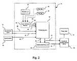
- FIG. 2is a block diagram of a speed limiting device included in a vehicle according to a second embodiment of the invention, wherein the speed of the vehicle is controlled using electronic throttle control (ETC);
- ETCelectronic throttle control
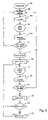
- FIG. 3is a flow chart describing a speed limiting mode of a speed limiting device processing unit according to one embodiment of the invention
- FIG. 4is a flow chart describing a non speed limiting mode of a speed limiting device processing unit according to one embodiment of the invention
- FIG. 5is a flow chart describing a program mode of a speed limiting device processing unit according to one embodiment of the invention.
- FIG. 6is a flow chart describing an interrupt of a speed limiting device processing unit according to one embodiment of the invention.
- FIG. 7is flow chart describing a method for preventing a speed of a vehicle to exceed a speed limit value by altering acceleration pedal position signals
- FIG. 8is flow chart describing a method for programming a speed limit value in a speed limiting device installed in a vehicle.
- the vehicle speed limiting deviceis a device that enables the owner or input user of a car or other vehicle to set a speed limit value and prevents the vehicle from exceeding this particular value in speed limiting mode.
- the input useris able to select between speed limiting and non speed limiting modes by the use of a remote unit.
- An output useris unable to activate, deactivate or program a speed limit. It thus allows a parent, the input user, to limit the speed at which their children, output users, can drive the car.
- the speed limiting deviceis designed to be installed on conventional fuel injected engine cars and can be installed alternatively on other vehicles such as trucks, buses or all-terrain vehicles.
- the speed of a conventional caris controlled by a foot-operated acceleration pedal.
- the acceleration pedalis in electrical communication with the throttle valve through an engine control unit (ECU) or an electronic throttle controller (ETC), also sometimes referred to as the throttle control unit (TCU).
- ECUengine control unit
- ETCelectronic throttle controller
- engine sensorsprovide airflow measurements to the onboard computer which controls fuel flow to obtain a desired air/fuel ratio.
- the acceleration pedalgenerates two acceleration pedal position (APP) signals, a low voltage and a high voltage APP signal.
- the two APP signalsare received by the ECU or by the ETC to control the acceleration of the car.
- the “acceleration pedal”can be more generally called an “acceleration control device” and the “APP signals”, “acceleration control signals”.
- the speed limiting devicereceives the APP signals from the acceleration pedal.
- the deviceWhen in non speed limiting mode, the device simply forwards the APP signals to the ECU or the ETC.
- the devicemakes no change to the APP signals if the vehicle speed is below the speed limit value and alters the APP signals if the vehicle speed reaches the speed limit value, in order to limit the speed of the car. Altering the APP signals has the same effect as if the driver was reducing foot pressure to the accelerator pedal.
- FIG. 1illustrates a speed limiting device 10 installed in a car between the acceleration pedal 12 and the ECU 16 .
- the speed limiting device 10receives high voltage 20 and low voltage 22 input APP signals from an acceleration pedal 12 , and a vehicle speed signal 24 from the vehicle speed sensor 14 , and provides high voltage 52 and low voltage 54 altered APP signals to the ECU 16 .
- the ECUcontrols the power train 19 which includes engine control parameters such as the throttle valve signal, the injector pulses and, possibly, gear selection.
- the speed limiting device 10comprises a processing unit 30 , a remote unit 32 to be carried by an input user, a user interface receiver 34 to receive the information from the remote unit 32 and a signal generating unit 36 .
- the remote unit 32comprises three push-buttons, a “program” button 40 , an “activate” button 42 and a “deactivate” button 44 .
- the remote unit 32is wirelessly connected to the user interface receiver 34 using radio frequency, infrared or another wireless protocol. It can be carried as a key fob by the input user. This unit allows only the input user, having the remote unit 32 with her or him, to change the settings of the speed limiting device, i.e. to activate or deactivate speed limiting or to program a speed limit value. Output users, who do not have access to the remote unit 32 , are unable to change the settings.
- the user interface receiver 34receive instructions from the remote unit 32 and transmits programming 46 , activating 48 and deactivating 50 signals to the processing unit 30 .
- the processing unit 30receives the high voltage 20 and low voltage 22 input APP signals, the vehicle speed signal 24 and the programming 46 , activating 48 and deactivating 50 signals, and provides a high voltage output APP signal 52 .
- the processing unit 30activates the speed limiting mode.
- the speed limiting modestays active until a deactivating signal 50 is received.
- the high voltage output APP signal 52is identical to the high voltage input APP signal 20 if the vehicle speed signal 24 indicates that the vehicle speed is below the speed limit value, and the high voltage output APP signal 52 is altered compared to the high voltage input APP signal 20 if the vehicle speed has reached the speed limit value, as will be described further below.
- the low voltage input APP signal 22is used in cooperation with the high voltage input APP signal 20 during a calibration procedure, as will also be described further below.
- the processing unitis a microcontroller with A/D converter and D/A converter such as Microchip PIC16C781 microcontroller.
- the processing unit 30comprises analog to digital converters (not shown) to convert the analog high voltage 20 and low voltage 22 input APP signals into digital signals to be processed. An altered digital signal is subsequently converted into the analog high voltage altered APP signal 52 using a digital to analog converter (not shown).
- the vehicle speed signal 24 received from the speed sensor 14is an alternating signal. Depending on the model of the speed sensor 14 provided with the car, the vehicle speed signal 24 may be an analog alternating signal or a digital alternating signal. In both cases, the vehicle speed is determined from the frequency of the alternating signal.
- the vehicle speed signal 24is amplified and conditioned such that an analog sine wave is converted to a digital square wave for frequency measurement. If the vehicle speed signal is digital, it passes through the same path but no change appears to it.
- the low voltage output APP signal 54is generated using the signal generating unit 36 which receives the high voltage output APP signal 52 .
- the signal generating unit 36is a digital potentiometer that comprises a non-volatile memory, a MCP41XXX for instance.
- the acceleration pedal 12generates two signals, the high voltage 20 and low voltage 22 input APP signals.
- the ECUrequires both signals in order to work properly. If the ECU does not receive a high and a low voltage signal, it may generate an error or go into a limp mode.
- the high 20 to low 22 voltage input APP signals ratiois substantially constant during operation. It is thus once characterized automatically each time the car is started, and its value is stored in the signal generating unit 36 . When properly calibrated, the signal generating unit 36 will ensure that the high 52 to low 54 voltage output signal ratio is equal to the high 20 to low 22 voltage input APP signal ratio.
- the signal generating unit 36receives a calibration signal 56 from the processing unit 30 for calibration purposes,
- FIG. 2shows a speed limiting device 10 ′ installed in a car using an ETC instead of the ECU.
- the ETCdirectly controls the power train 19 which includes engine control parameters such as the throttle valve signal, the injector pulses and, possibly, gear selection.
- the ETCrequires receiving both high voltage 52 and low voltage 54 altered APP signals to function properly and not to generate an error.
- key tags 58may be used in order to differentiate between the different car users. For instance, the key tags 58 may use radio frequency identification technology. The use of key tags 58 would allow for a different maximum speed to be associated to each user. It would also provide for increased security against thieves by disconnecting the accelerator until there is a valid recognized key tag 58 .
- Both devices 10 and 10 ′can be installed alternatively on cars using an ECU and cars using an ETC.
- FIG. 3describes the speed limiting mode 302 behavior of the processing unit.
- the processing unitmonitors the speed of the vehicle using the frequency of the vehicle speed signal while forwarding the high voltage APP signal without alteration.
- the speed reaches the speed limit valuethe high voltage APP signal is altered to reduce the acceleration of the vehicle so that the speed does not exceed the speed limit value.
- the processing unit incoming signalsare digitized, as described above, so that the speed limiting mode 302 receives a digital input APP value (APPv) and a digital speed value (VSS).
- APPvdigital input APP value
- VSSdigital speed value
- the resulting altered APP value (aAPP)is converted into analog high voltage altered APP signal.
- the speed limiting mode 302starts in a no change condition 304 in which the input APP value (APPv) is inputted in step 306 and forwarded to the ECU in step 306 with no change in value.
- step 310the speed value (VSS) is inputted and compared to the speed limit value in step 312 . If the speed value (VSS) exceeds the speed limit value, the change condition 314 starts. Otherwise, the no change condition 304 restarts.
- the change condition 314starts, in step 316 , the altered APP value (APP) is made equal to the input APP value (APPv) and reduced by one digit.
- the resulting altered APP value (aAPP)is outputted to the ECU in step 318 .
- step 320the speed value (VSS) is inputted and compared to the speed limit value in step 322 . If the speed value (VSS) does not exceed the speed limit value, the no change condition 304 restarts. Otherwise, the altered APP value (aAPP) is reduced again by one digit in step 324 .
- step 326the altered APP value (aAPP) is compared to a minimal APP value default setting (minAPP). If the altered APP value (aAPP) is lower than the minimal APP value (minAPP), the altered APP value (aAPP) is increased of one digit is step 328 and the system then goes back to step 318 . Otherwise, it goes back to step 318 directly
- FIG. 4illustrates the non speed limiting mode 402 of the processing unit. While in non speed limiting mode, the processing unit simply forwards the input APP value (APPv) to the ECU with no change in value.
- the non speed limiting mode 402starts with step 404 in which the input APP value (APPv) is inputted. In step 406 , it is forwarded to the ECU. The system then goes back to step 404 .
- FIG. 5describes the program mode 502 of the processing unit.
- This modeallows the input user of the car to set the speed limit value equal to the speed at which he or she is currently driving the car.
- the program mode 502starts with step 504 in which the speed value (VSS) is inputted.
- step 506the speed limit value in set to be equal to the speed value (VSS).
- the program modethen ends. As will be explained further below, the processing unit then goes back to the mode that was active before an interrupt caused it to go in the program mode.
- Switches between the limiting, the non limiting and the program modesare caused by interrupts.
- the user interfacereceives the instruction and sends an activating signal to the processing unit. This event generates an interrupt and the system goes into speed limiting mode. The same process occurs for the other two buttons.
- FIG. 6shows the interrupt 602 process in response to the use of the remote unit.
- the current modeis saved in step 604 .
- the instruction valueis inputted.
- step 608if the instruction is an activating instruction, the system goes into the speed limiting mode 302 , if the instruction is a deactivating instruction, the system goes into the non speed limiting mode 402 and if the instruction is a programming instruction, the system goes into the program mode 502 .
- the speed limiting 302 and the non speed limiting 402 modesare continuous and will continue until another interrupt 602 arises.
- the program mode 502is different.
- step 616checks what the previous mode was (saved in step 604 ). It then goes into this previous mode, i.e. the speed limiting mode 302 or the non speed limiting mode 402 .
- FIG. 7illustrates a method for preventing the speed of a vehicle to exceed a speed limit value by altering APP signals received by the engine control unit.
- a first and a second input APP signal and a vehicle speed signalare received.
- a first altered APP signalis generated from the first input APP signal.
- the first altered APP signal and the first input APP signalhave equal voltage values when the speed value is lower than the speed limit value and the first altered APP signal and the first input APP signal have different voltage values when the speed value reaches the speed limit value.
- a second altered APP signalis produced.
- the second altered APP signalhas a ratio to the first altered APP signal that is equal to a ratio of the second to the first input APP signal.
- FIG. 8shows a method for programming the speed limit value in a speed limiting device installed in a vehicle.
- a vehicle speed signal representative of the current speed of the vehicleis received.
- a programming instructionis receiving.
- the speed valueis consequently stored to provide the speed limit value.
- the remote unitcan be directly linked to the processing unit using electrical connections.
- the remote unitcould be removable and thus still be carried on by an input user, or it could be fixed and be protected by the use of a password, in order that only the input user could change the settings of the speed limiting device.
- the speed limit valueis programmed by driving the vehicle at a desired speed limit and by providing a programming instruction using the push-button.
- the speed limit valuecould be entered using a user interface having a keyboard.
- the user interfacecould then be removable so that it is to be carried on by the input user, and thus acting as a key or the user interface may be protected by password.
- the activating, deactivating and programming instructionscould be provided using voice recognition or other means.
- the speed limiting device settingscould then be protected by the use of a password, a key, a key card or speaker recognition.
- the acceleration control deviceis an acceleration pedal as installed in most vehicles.
- the acceleration control devicecould be an acceleration lever or buttons as those installed for handicapped drivers.
- the low voltage APP signalcould be generated by the processing unit and the high voltage APP signal be generated by the signal generating unit, using the low voltage APP signal.
- a combination of the processing unit and the signal generating unitis a main unit.
- the relationship between high and low voltage APP signalscould be saved in the system using a look up table instead of a fixed ratio. This would allow characterizing and storing a variable ratio.
- both the high and the low voltage altered APP signalscould be generated directly from the high and the low voltage input APP signals.
- the main unitis the processing unit.
- acceleration control signalse.g. the APP signals
- the acceleration control signalsare analog voltage signals generated by the acceleration pedal and received by the ECU or the ETC.
- APP signalscould alternatively be analog current signals, digital signals or any signals generated by an acceleration control device and to be received by a throttle control device.
- the speed limiting devicecould then be adapted to receive and to generate these alternative signals.
- the acceleration control signalse.g. the APP signals
- the acceleration control signalscould be directed to any device effective on the acceleration of the vehicle.
- the acceleration control signalscould be directed to a digital throttle controller or to an injection controller if the vehicle on which the speed limiting device is to be installed uses one of these devices to control its acceleration.
Landscapes
- Engineering & Computer Science (AREA)
- Transportation (AREA)
- Mechanical Engineering (AREA)
- Automation & Control Theory (AREA)
- Chemical & Material Sciences (AREA)
- Combustion & Propulsion (AREA)
- Human Computer Interaction (AREA)
- Control Of Vehicle Engines Or Engines For Specific Uses (AREA)
- Controls For Constant Speed Travelling (AREA)
Abstract
Description
- a memory for storing said speed value upon reception of said programming signal to provide a value of said speed limit;
- whereby a user may, by driving said vehicle at a desired speed limit, provide said programming instruction to program said a value of speed limit as being a value of said desired speed limit; and
- receiving said vehicle speed signal;
- receiving a programming instruction; and
- storing said speed value to provide said speed limit value.
Claims (23)
Priority Applications (3)
| Application Number | Priority Date | Filing Date | Title |
|---|---|---|---|
| US11/418,120US7184873B1 (en) | 2006-05-05 | 2006-05-05 | Vehicle speed limiting device |
| CA2685755ACA2685755C (en) | 2006-05-05 | 2007-05-04 | Vehicle speed limiting device |
| PCT/CA2007/000756WO2007128108A1 (en) | 2006-05-05 | 2007-05-04 | Vehicle speed limiting device |
Applications Claiming Priority (1)
| Application Number | Priority Date | Filing Date | Title |
|---|---|---|---|
| US11/418,120US7184873B1 (en) | 2006-05-05 | 2006-05-05 | Vehicle speed limiting device |
Publications (1)
| Publication Number | Publication Date |
|---|---|
| US7184873B1true US7184873B1 (en) | 2007-02-27 |
Family
ID=37769716
Family Applications (1)
| Application Number | Title | Priority Date | Filing Date |
|---|---|---|---|
| US11/418,120Expired - Fee RelatedUS7184873B1 (en) | 2006-05-05 | 2006-05-05 | Vehicle speed limiting device |
Country Status (3)
| Country | Link |
|---|---|
| US (1) | US7184873B1 (en) |
| CA (1) | CA2685755C (en) |
| WO (1) | WO2007128108A1 (en) |
Cited By (30)
| Publication number | Priority date | Publication date | Assignee | Title |
|---|---|---|---|---|
| WO2009008816A1 (en)* | 2007-07-11 | 2009-01-15 | Husqvarna Ab | Atv with electronic throttle control |
| EP2055601A1 (en)* | 2007-10-29 | 2009-05-06 | MAGNETI MARELLI POWERTRAIN S.p.A. | Control method for limiting the performances of a road vehicle |
| US20090146844A1 (en)* | 2007-12-07 | 2009-06-11 | Reza Mohamed Hassan | SpeedSense, an Intelligent Electronic Top Speed Control Automotive Safety Device |
| EP2078641A1 (en)* | 2008-01-10 | 2009-07-15 | Fiat Group Automobiles S.p.A. | On-vehicle infotelematic system and method for setting a vehicle performance profile using said system |
| WO2009090459A1 (en)* | 2007-12-21 | 2009-07-23 | Gentile Verri | Management device of the performance of a motor vehicle |
| US20090198413A1 (en)* | 2008-02-06 | 2009-08-06 | Ford Global Technologies, Llc | System and method for controlling electronic stability control based on driver status |
| US20090201140A1 (en)* | 2006-06-23 | 2009-08-13 | Nodbox | Method for determining the driving limits of a vehicle |
| US20100100295A1 (en)* | 2007-04-27 | 2010-04-22 | Toyota Jidosha Kabushiki Kaisha | Vehicle speed control system and vehicle speed control method of vehicle |
| EP2192015A1 (en)* | 2008-11-26 | 2010-06-02 | Fiat Group Automobiles S.p.A. | Automatic setting of a motor vehicle performance profile |
| US20100241313A1 (en)* | 2006-07-14 | 2010-09-23 | Richard Fiske | Motor vehicle operator identification and maximum speed limiter |
| US20120215413A1 (en)* | 2011-02-23 | 2012-08-23 | Textron Inc. | Electronic Passcode Key for Varying Operational Parameters of a Vehicle |
| US8534397B2 (en) | 2010-06-03 | 2013-09-17 | Polaris Industries Inc. | Electronic throttle control |
| CN104228581A (en)* | 2014-10-09 | 2014-12-24 | 重庆电子工程职业学院 | Vehicle forced speed limiting method |
| WO2016079617A1 (en)* | 2014-11-17 | 2016-05-26 | Stamatios Boulekos | Device and method for electronic locking of pedal of vehicles equipped with drive by wire system |
| WO2017137735A1 (en)* | 2016-02-09 | 2017-08-17 | Autokontrol Limited | Speed limiter system |
| US20210031782A1 (en)* | 2019-08-01 | 2021-02-04 | 7980302 Canada Inc. | Using ISA System to Immobilize Truck for Security, Regulatory Compliance, or Maintenance |
| US11373502B2 (en)* | 2018-01-31 | 2022-06-28 | Denso Corporation | Vehicle alert apparatus |
| US11572067B2 (en) | 2019-08-30 | 2023-02-07 | 7980302 Canada Inc. | Using ISA system to decelerate truck upon entering geofenced area |
| US20230186215A1 (en)* | 2021-12-15 | 2023-06-15 | Hyundai Motor Company | Vehicle rental method based on a safe driving grade and a server using the same |
| US11702083B2 (en) | 2020-06-11 | 2023-07-18 | 7980302 Canada Inc. | Using ISA system to implement a speed policy identified based on profile of a driving instance |
| US11878678B2 (en) | 2016-11-18 | 2024-01-23 | Polaris Industries Inc. | Vehicle having adjustable suspension |
| US11904648B2 (en) | 2020-07-17 | 2024-02-20 | Polaris Industries Inc. | Adjustable suspensions and vehicle operation for off-road recreational vehicles |
| US11912096B2 (en) | 2017-06-09 | 2024-02-27 | Polaris Industries Inc. | Adjustable vehicle suspension system |
| US11919524B2 (en) | 2014-10-31 | 2024-03-05 | Polaris Industries Inc. | System and method for controlling a vehicle |
| US11970036B2 (en) | 2012-11-07 | 2024-04-30 | Polaris Industries Inc. | Vehicle having suspension with continuous damping control |
| US11975584B2 (en) | 2018-11-21 | 2024-05-07 | Polaris Industries Inc. | Vehicle having adjustable compression and rebound damping |
| US20240176343A1 (en)* | 2022-10-24 | 2024-05-30 | WOW Technologies LLC | System and method of rf speed control for high-performance vehicles |
| WO2024197421A1 (en)* | 2023-03-29 | 2024-10-03 | 7980302 Canada Inc. | Safe vehicle speed limiter |
| US12227181B2 (en) | 2019-08-01 | 2025-02-18 | 7980302 Canada Inc. | Simulating braking when speeding on cruise control to facilitate use of ISA system |
| US12397878B2 (en) | 2020-05-20 | 2025-08-26 | Polaris Industries Inc. | Systems and methods of adjustable suspensions for off-road recreational vehicles |
Families Citing this family (2)
| Publication number | Priority date | Publication date | Assignee | Title |
|---|---|---|---|---|
| CN103568841B (en)* | 2013-11-15 | 2016-04-13 | 浙江工贸职业技术学院 | A kind of direct injection oil-fired vehicle speed limit control system |
| GB2568765A (en)* | 2017-11-28 | 2019-05-29 | Ecomatics Ltd | A device and method for remotely managing driving behavior |
Citations (10)
| Publication number | Priority date | Publication date | Assignee | Title |
|---|---|---|---|---|
| US3878915A (en) | 1973-08-24 | 1975-04-22 | Digi Gard Inc | Electronic motor vehicle speed control apparatus |
| WO1984003785A1 (en) | 1983-03-12 | 1984-09-27 | Ernst Hans Hellmut | Start, operation and control device for motor vehicles |
| EP0843177A1 (en) | 1996-11-12 | 1998-05-20 | Eletec Elettronica e Tecnologia di Spadaro Nuccio | Device for measuring the speed of a means of locomotion and signal it to the driver as a function of a comparison with a pre-set reference value |
| US6098007A (en)* | 1996-08-10 | 2000-08-01 | Daimlerchrysler Ag | Control arrangement for longitudinal dynamics of a motor vehicle |
| US6188949B1 (en) | 1998-05-15 | 2001-02-13 | Daimlerchrysler Ag | Method and arrangement for controlling the longitudinal velocity of a motor vehicle |
| US6198996B1 (en) | 1999-01-28 | 2001-03-06 | International Business Machines Corporation | Method and apparatus for setting automotive performance tuned preferences set differently by a driver |
| US6273204B1 (en)* | 1996-10-02 | 2001-08-14 | Robert Bosch Gmbh | Method and arrangement for controlling the speed of a vehicle |
| US6285945B1 (en)* | 1999-12-22 | 2001-09-04 | Visteon Global Technologies, Inc. | Method and system for controlling vehicle deceleration in an adaptive speed control system based on vehicle speed |
| US20020170762A1 (en) | 2001-05-21 | 2002-11-21 | Daneshmand Mohammad R. | Automobile speed limiter system |
| WO2004007930A2 (en) | 2002-07-16 | 2004-01-22 | Dorsey Innovations, Inc. | Vehicle speed limiting method and apparatus |
- 2006
- 2006-05-05USUS11/418,120patent/US7184873B1/ennot_activeExpired - Fee Related
- 2007
- 2007-05-04WOPCT/CA2007/000756patent/WO2007128108A1/enactiveApplication Filing
- 2007-05-04CACA2685755Apatent/CA2685755C/ennot_activeExpired - Fee Related
Patent Citations (12)
| Publication number | Priority date | Publication date | Assignee | Title |
|---|---|---|---|---|
| US3878915A (en) | 1973-08-24 | 1975-04-22 | Digi Gard Inc | Electronic motor vehicle speed control apparatus |
| WO1984003785A1 (en) | 1983-03-12 | 1984-09-27 | Ernst Hans Hellmut | Start, operation and control device for motor vehicles |
| US6098007A (en)* | 1996-08-10 | 2000-08-01 | Daimlerchrysler Ag | Control arrangement for longitudinal dynamics of a motor vehicle |
| US6273204B1 (en)* | 1996-10-02 | 2001-08-14 | Robert Bosch Gmbh | Method and arrangement for controlling the speed of a vehicle |
| EP0843177A1 (en) | 1996-11-12 | 1998-05-20 | Eletec Elettronica e Tecnologia di Spadaro Nuccio | Device for measuring the speed of a means of locomotion and signal it to the driver as a function of a comparison with a pre-set reference value |
| US6188949B1 (en) | 1998-05-15 | 2001-02-13 | Daimlerchrysler Ag | Method and arrangement for controlling the longitudinal velocity of a motor vehicle |
| US6198996B1 (en) | 1999-01-28 | 2001-03-06 | International Business Machines Corporation | Method and apparatus for setting automotive performance tuned preferences set differently by a driver |
| US6285945B1 (en)* | 1999-12-22 | 2001-09-04 | Visteon Global Technologies, Inc. | Method and system for controlling vehicle deceleration in an adaptive speed control system based on vehicle speed |
| US6393352B2 (en)* | 1999-12-22 | 2002-05-21 | Visteon Global Technologies, Inc. | Method and system for controlling vehicle deceleration in an adaptive speed control system based on vehicle speed |
| US6604043B2 (en)* | 1999-12-22 | 2003-08-05 | Visteon Global Technologies, Inc. | Method and system for controlling vehicle deceleration in an adaptive speed control system based on vehicle speed |
| US20020170762A1 (en) | 2001-05-21 | 2002-11-21 | Daneshmand Mohammad R. | Automobile speed limiter system |
| WO2004007930A2 (en) | 2002-07-16 | 2004-01-22 | Dorsey Innovations, Inc. | Vehicle speed limiting method and apparatus |
Cited By (46)
| Publication number | Priority date | Publication date | Assignee | Title |
|---|---|---|---|---|
| US20090201140A1 (en)* | 2006-06-23 | 2009-08-13 | Nodbox | Method for determining the driving limits of a vehicle |
| US8599005B2 (en)* | 2006-06-23 | 2013-12-03 | Nodbox | Method for determining the driving limits of a vehicle |
| US8256560B2 (en) | 2006-07-14 | 2012-09-04 | Kar Enterprises, Llc | Motor vehicle operator identification and maximum speed limiter |
| US7959177B2 (en) | 2006-07-14 | 2011-06-14 | Kar Enterprises, Llc | Motor vehicle operator identification and maximum speed limiter |
| US20100241313A1 (en)* | 2006-07-14 | 2010-09-23 | Richard Fiske | Motor vehicle operator identification and maximum speed limiter |
| US8818677B2 (en)* | 2007-04-27 | 2014-08-26 | Toyota Jidosha Kabushiki Kaisha | System and method of vehicle speed control having vehicle speed limit control and speed increase rate control |
| US20100100295A1 (en)* | 2007-04-27 | 2010-04-22 | Toyota Jidosha Kabushiki Kaisha | Vehicle speed control system and vehicle speed control method of vehicle |
| WO2009008816A1 (en)* | 2007-07-11 | 2009-01-15 | Husqvarna Ab | Atv with electronic throttle control |
| US20090143961A1 (en)* | 2007-10-29 | 2009-06-04 | Magneti Marelli Powertrain S.P.A. | Road vehicle control method |
| EP2055601A1 (en)* | 2007-10-29 | 2009-05-06 | MAGNETI MARELLI POWERTRAIN S.p.A. | Control method for limiting the performances of a road vehicle |
| US20090146844A1 (en)* | 2007-12-07 | 2009-06-11 | Reza Mohamed Hassan | SpeedSense, an Intelligent Electronic Top Speed Control Automotive Safety Device |
| WO2009090459A1 (en)* | 2007-12-21 | 2009-07-23 | Gentile Verri | Management device of the performance of a motor vehicle |
| EP2078641A1 (en)* | 2008-01-10 | 2009-07-15 | Fiat Group Automobiles S.p.A. | On-vehicle infotelematic system and method for setting a vehicle performance profile using said system |
| US20090198413A1 (en)* | 2008-02-06 | 2009-08-06 | Ford Global Technologies, Llc | System and method for controlling electronic stability control based on driver status |
| US8280580B2 (en)* | 2008-02-06 | 2012-10-02 | Ford Global Technologies, Llc | System and method for controlling electronic stability control based on driver status |
| EP2192015A1 (en)* | 2008-11-26 | 2010-06-02 | Fiat Group Automobiles S.p.A. | Automatic setting of a motor vehicle performance profile |
| US9381810B2 (en) | 2010-06-03 | 2016-07-05 | Polaris Industries Inc. | Electronic throttle control |
| US10933744B2 (en) | 2010-06-03 | 2021-03-02 | Polaris Industries Inc. | Electronic throttle control |
| US8534397B2 (en) | 2010-06-03 | 2013-09-17 | Polaris Industries Inc. | Electronic throttle control |
| US10086698B2 (en) | 2010-06-03 | 2018-10-02 | Polaris Industries Inc. | Electronic throttle control |
| US9162573B2 (en) | 2010-06-03 | 2015-10-20 | Polaris Industries Inc. | Electronic throttle control |
| US20120215413A1 (en)* | 2011-02-23 | 2012-08-23 | Textron Inc. | Electronic Passcode Key for Varying Operational Parameters of a Vehicle |
| US8554437B2 (en)* | 2011-02-23 | 2013-10-08 | Textron Inc. | Electronic passcode key for varying operational parameters of a vehicle |
| US12291069B2 (en) | 2012-11-07 | 2025-05-06 | Polaris Industries Inc. | Vehicle having suspension with continuous damping control |
| US11970036B2 (en) | 2012-11-07 | 2024-04-30 | Polaris Industries Inc. | Vehicle having suspension with continuous damping control |
| CN104228581A (en)* | 2014-10-09 | 2014-12-24 | 重庆电子工程职业学院 | Vehicle forced speed limiting method |
| US12325432B2 (en) | 2014-10-31 | 2025-06-10 | Polaris Industries Inc. | System and method for controlling a vehicle |
| US11919524B2 (en) | 2014-10-31 | 2024-03-05 | Polaris Industries Inc. | System and method for controlling a vehicle |
| WO2016079617A1 (en)* | 2014-11-17 | 2016-05-26 | Stamatios Boulekos | Device and method for electronic locking of pedal of vehicles equipped with drive by wire system |
| WO2017137735A1 (en)* | 2016-02-09 | 2017-08-17 | Autokontrol Limited | Speed limiter system |
| US11878678B2 (en) | 2016-11-18 | 2024-01-23 | Polaris Industries Inc. | Vehicle having adjustable suspension |
| US12337824B2 (en) | 2016-11-18 | 2025-06-24 | Polaris Industries Inc. | Vehicle having adjustable suspension |
| US11912096B2 (en) | 2017-06-09 | 2024-02-27 | Polaris Industries Inc. | Adjustable vehicle suspension system |
| US12330467B2 (en) | 2017-06-09 | 2025-06-17 | Polaris Industries Inc. | Adjustable vehicle suspension system |
| US11373502B2 (en)* | 2018-01-31 | 2022-06-28 | Denso Corporation | Vehicle alert apparatus |
| US11975584B2 (en) | 2018-11-21 | 2024-05-07 | Polaris Industries Inc. | Vehicle having adjustable compression and rebound damping |
| US12384214B2 (en) | 2018-11-21 | 2025-08-12 | Polaris Industries Inc. | Vehicle having adjustable compression and rebound damping |
| US12227181B2 (en) | 2019-08-01 | 2025-02-18 | 7980302 Canada Inc. | Simulating braking when speeding on cruise control to facilitate use of ISA system |
| US20210031782A1 (en)* | 2019-08-01 | 2021-02-04 | 7980302 Canada Inc. | Using ISA System to Immobilize Truck for Security, Regulatory Compliance, or Maintenance |
| US11572067B2 (en) | 2019-08-30 | 2023-02-07 | 7980302 Canada Inc. | Using ISA system to decelerate truck upon entering geofenced area |
| US12397878B2 (en) | 2020-05-20 | 2025-08-26 | Polaris Industries Inc. | Systems and methods of adjustable suspensions for off-road recreational vehicles |
| US11702083B2 (en) | 2020-06-11 | 2023-07-18 | 7980302 Canada Inc. | Using ISA system to implement a speed policy identified based on profile of a driving instance |
| US11904648B2 (en) | 2020-07-17 | 2024-02-20 | Polaris Industries Inc. | Adjustable suspensions and vehicle operation for off-road recreational vehicles |
| US20230186215A1 (en)* | 2021-12-15 | 2023-06-15 | Hyundai Motor Company | Vehicle rental method based on a safe driving grade and a server using the same |
| US20240176343A1 (en)* | 2022-10-24 | 2024-05-30 | WOW Technologies LLC | System and method of rf speed control for high-performance vehicles |
| WO2024197421A1 (en)* | 2023-03-29 | 2024-10-03 | 7980302 Canada Inc. | Safe vehicle speed limiter |
Also Published As
| Publication number | Publication date |
|---|---|
| WO2007128108A1 (en) | 2007-11-15 |
| CA2685755C (en) | 2014-04-01 |
| CA2685755A1 (en) | 2007-11-15 |
Similar Documents
| Publication | Publication Date | Title |
|---|---|---|
| US7184873B1 (en) | Vehicle speed limiting device | |
| US7959177B2 (en) | Motor vehicle operator identification and maximum speed limiter | |
| US8258937B2 (en) | System for transmitting data between a hybrid electric vehicle and a remote transceiver | |
| EP1887447B1 (en) | Safety instrumentation system and plant safety system | |
| US6344793B1 (en) | Process for assisting a user of a motor vehicle when operating components of the motor vehicle as well as a pertaining system | |
| US8305189B2 (en) | System and method for changing key status in a vehicle based on driver status | |
| US20050078423A1 (en) | Controller for electric power supply of electronic device supplied with electric power from battery of vehicle | |
| JP2003511588A (en) | Vehicle access system with electronic key and valet operating mode | |
| US7699133B2 (en) | Throttle disable method and system | |
| CA2228330A1 (en) | Keyless ignition system with delayed security | |
| US20020170762A1 (en) | Automobile speed limiter system | |
| US20230242047A1 (en) | Touchscreen-Based Vehicle Control Interface | |
| CN112477806B (en) | Vehicle control method, vehicle, and storage medium | |
| US20130345914A1 (en) | Vehicle speed limiting via engine control commands based on sensed machine state | |
| EP1034980A3 (en) | Control system for a vehicle situated device | |
| US6888265B2 (en) | Motor vehicle immobilizer with key-in warning responsive to ignition state | |
| US20150091378A1 (en) | Method for activating or deactivating functions and device for influencing functions in a motor vehicle | |
| US20080100137A1 (en) | Intelligent wiper control system for vehicle | |
| US6276332B1 (en) | Electronic airflow control | |
| US20070156321A1 (en) | Speed regulation system for vehicles | |
| US6445083B2 (en) | Method and device for controlling a power adjustment means of a vehicle engine | |
| US20230339318A1 (en) | Control module for electronic accelerator | |
| WO2016079617A1 (en) | Device and method for electronic locking of pedal of vehicles equipped with drive by wire system | |
| JP3315561B2 (en) | Automotive electronic control unit | |
| CN109383466B (en) | Advanced brake priority device and method thereof |
Legal Events
| Date | Code | Title | Description |
|---|---|---|---|
| AS | Assignment | Owner name:STANOX TECHNOLOGIES INC., CANADA Free format text:ASSIGNMENT OF ASSIGNORS INTEREST;ASSIGNORS:IDSINGA, ROBERT M.;PEPIN, ALEXANDRE J.G.R.;CREAGAN, BRYAN LEONARD;REEL/FRAME:017872/0229;SIGNING DATES FROM 20060228 TO 20060411 | |
| STCF | Information on status: patent grant | Free format text:PATENTED CASE | |
| FPAY | Fee payment | Year of fee payment:4 | |
| AS | Assignment | Owner name:SODO, PETER, CANADA Free format text:ASSIGNMENT OF ASSIGNORS INTEREST;ASSIGNOR:STANOX TECHNOLOGIES INC.;REEL/FRAME:032467/0618 Effective date:20140228 | |
| REMI | Maintenance fee reminder mailed | ||
| FPAY | Fee payment | Year of fee payment:8 | |
| SULP | Surcharge for late payment | Year of fee payment:7 | |
| FEPP | Fee payment procedure | Free format text:MAINTENANCE FEE REMINDER MAILED (ORIGINAL EVENT CODE: REM.); ENTITY STATUS OF PATENT OWNER: SMALL ENTITY | |
| LAPS | Lapse for failure to pay maintenance fees | Free format text:PATENT EXPIRED FOR FAILURE TO PAY MAINTENANCE FEES (ORIGINAL EVENT CODE: EXP.); ENTITY STATUS OF PATENT OWNER: SMALL ENTITY | |
| STCH | Information on status: patent discontinuation | Free format text:PATENT EXPIRED DUE TO NONPAYMENT OF MAINTENANCE FEES UNDER 37 CFR 1.362 | |
| FP | Lapsed due to failure to pay maintenance fee | Effective date:20190227 |