US7184825B2 - Needless medical connector having antimicrobial agent - Google Patents
Needless medical connector having antimicrobial agentDownload PDFInfo
- Publication number
- US7184825B2 US7184825B2US10/143,619US14361902AUS7184825B2US 7184825 B2US7184825 B2US 7184825B2US 14361902 AUS14361902 AUS 14361902AUS 7184825 B2US7184825 B2US 7184825B2
- Authority
- US
- United States
- Prior art keywords
- inlet port
- connector
- valve assembly
- flex
- fluid path
- Prior art date
- Legal status (The legal status is an assumption and is not a legal conclusion. Google has not performed a legal analysis and makes no representation as to the accuracy of the status listed.)
- Expired - Lifetime, expires
Links
Images


Classifications
- A—HUMAN NECESSITIES
- A61—MEDICAL OR VETERINARY SCIENCE; HYGIENE
- A61M—DEVICES FOR INTRODUCING MEDIA INTO, OR ONTO, THE BODY; DEVICES FOR TRANSDUCING BODY MEDIA OR FOR TAKING MEDIA FROM THE BODY; DEVICES FOR PRODUCING OR ENDING SLEEP OR STUPOR
- A61M39/00—Tubes, tube connectors, tube couplings, valves, access sites or the like, specially adapted for medical use
- A61M39/22—Valves or arrangement of valves
- A61M39/26—Valves closing automatically on disconnecting the line and opening on reconnection thereof
- A61M2039/263—Valves closing automatically on disconnecting the line and opening on reconnection thereof where the fluid space within the valve is decreasing upon disconnection
Definitions
- the inventionrelates generally to medical connectors of the type used in the handling and administration of parenteral fluids, and more particularly, to a needleless connector employing a valve mechanism that compensates for negative fluid displacement, i.e., drawing of fluid into the outlet end of a connector, during deactuation of the valve.
- negative-bolus effectdescribes the condition during which fluid is drawn into the connector during deactuation.
- Positive-bolus effectdescribes the condition during which fluid is flushed out of the connector during deactuation.
- No-bolus effectdescribes the condition during which fluid displacement is neutralized and fluid is neither drawn into nor flushed out of the connector during deactuation.
- Needleless medical connectors for injecting fluid into or removing fluid from an intravenous (IV) systemare well known and widely used.
- Conventional needleless medical connectorsgenerally include a housing having an inlet port and an outlet port.
- the inlet portis sized to receive a blunt male cannula, such as a male Luer taper.
- a valve mechanismDisposed within the inlet port is a valve mechanism that provides access to a fluid path that communicates with the outlet port.
- the fluid pathis defined by the internal boundaries of the connector housing, in other connectors it is defined by an internal cannula or hollow spike, still in others, the fluid path is defined by a compressible tubular body which carries the valve mechanism.
- the outlet port of the connectoris typically connected to IV tubing which in turn is connected to an IV catheter that communicates with a patient's venous system.
- Many needleless medical connectorscreate fluid displacement during actuation and deactuation of the valve mechanism.
- the blunt male cannulais inserted into the inlet.
- the cannulapasses through the valve mechanism to establish fluid communication with the fluid path.
- the cannulamerely displaces the valve mechanism, without penetrating it, in order to establish fluid communication with the fluid path.
- the volumetric capacity of the fluid pathis often reduced by the insertion of the blunt cannula.
- the blunt cannulais removed from the connector, the volumetric capacity of the fluid path increases. This increase in the volumetric capacity may create a partial vacuum in the fluid path that may draw fluid into the connector from the outlet end.
- the effect of drawing fluid into the connector in this manneris referred to as a “negative-bolus” effect in that a quantity, or “bolus,” of fluid is drawn into the partial vacuum or negative pressure location; i.e., the connector.
- a negative-bolus effectis undesirable in that the partial vacuum created within the connector may draw fluid from the IV tubing.
- the IV tubingin turn draws fluid from the IV catheter which in turn draws fluid, e.g., blood, from the patient's venous system.
- the negative-bolus effectmay be reduced by undertaking operational safeguards. For instance, prior to the removal of the blunt cannula from the connector, the IV tubing may be clamped off between the connector output port and the IV catheter. This prevents the backup of blood through the IV catheter. If a syringe with a blunt cannula tip is used to inject fluid into the inlet port of the valve, the syringe may be continually depressed while the syringe is disengaged from the connector. The continued depression of the syringe injects fluid into the fluid path to fill the increasing volume thereby reducing the chance of a partial vacuum forming in the fluid path and a negative bolus.
- both of these approachesare undesirable in that the operator must remember to perform an additional step during removal of the syringe or other device from the connector rather than the steps being taken automatically by the connector.
- some medical connectorsinclude an internal cannula or hollow spike housed inside the connector body.
- the internal cannula or spikeis positioned to open a septum upon depression of the septum onto the internal cannula or spike by a blunt cannula.
- the internal cannula or spikehas a small orifice at the top and upon depression of the septum is put in fluid communication with the blunt cannula.
- the internal cannula or spikeprovides a generally fixed-volume fluid-flow path through the connector. Thus, as the septum returns to its closed position the partial vacuum formed within the connector is not as strong as the vacuum formed in a connector having a more volumetrically dynamic fluid path.
- a disadvantage of typical connectors having an internal cannula or spikeis a lower fluid-flow rate. This low flow rate is caused by the small orifice in the cannula or spike. Additionally, it has been noted that with the connector design having a fixedly-mounted internal spike and a movable septum that is pierced by that spike to permit fluid flow, such pierced septum may be damaged with multiple uses and a leaking connector may result.
- connectorsmay reduce the negative-bolus effect, they have several disadvantages.
- the inventionis directed to a medical connector having a valve mechanism that provides either a positive-bolus effect or a no-bolus effect, upon deactuation of the valve mechanism.
- the inventionis directed to a needleless connector for medical use, adapted to facilitate the flow of fluid therethrough.
- the connectorincludes a housing having an inlet port and an outlet port.
- the connectoralso includes a flex-tube assembly defining a fluid path between the inlet port and the outlet port.
- the flex-tube assemblyis movable between uncompressed and compressed states and has a first internal volume when in the uncompressed state and a second internal volume, at least as great as the first internal volume, when in the compressed state.
- a flex-tube assemblyhaving an internal volume when compressed, e.g., activated by the insertion of a blunt cannula, that is at least as great as the internal volume when the flex-tube assembly is uncompressed, the possibility of a partial vacuum forming within the fluid path defined by the flex-tube assembly upon removal of the blunt cannula is essentially eliminated and instead, a positive-bolus effect or a no-bolus effect is provided. Thus, fluid is prevented from being drawn into the connector through the outlet port upon removal of the blunt cannula.
- the second internal volumeis greater than the first internal volume. In another detailed facet, the second internal volume is substantially equal to the first internal volume.
- the flex-tube assemblyincludes an inlet end that is positioned within the inlet port during the uncompressed state and outside the inlet port during the compressed state. The flex-tube assembly also includes a bore carried by the inlet end. The bore is closed when the inlet end is within the inlet port and opened when the inlet end is outside the inlet port.
- the flex-tube assemblyincludes a flex-tube insert having at least one collapsible section movable between uncollapsed and collapsed states.
- the flex-tube assemblyalso includes a flex-tube piston that surrounds the flex-tube insert and defines the fluid path.
- the flex-tube pistonincludes a piston head that is positioned within the inlet port during the uncompressed state and outside the inlet port during the compressed state.
- the flex-tube pistonalso includes a bore that is carried by the piston head. The bore is closed when the piston head is within the inlet port and opened when the piston head is outside the inlet port.
- the flex-tube pistonfurther includes a piston base that is proximal the outlet port and in communication therewith. The flex-tube piston is responsive to the movement of the flex-tube insert.
- the flex-tube insertincludes one collapsible section and the first end is secured within the piston head and the second end is secured within the piston base.
- the flex-tube insertincludes two collapsible sections and a middle support for joining the two collapsible sections.
- the first endis secured within the piston head and the second end is pivotably attached to the middle support.
- the first endis pivotably attached to the middle support and the second end is secured within the piston base.
- the flex-tube assemblyincludes at least one collapsible section defining the fluid path, a piston head that is positioned within the inlet port during the uncompressed state and outside the inlet port during the compressed state, and a bore that is carried by the piston head. The bore is closed when the piston head is within the inlet port and opened when the piston head is outside the inlet port.
- the flex-tube assemblyalso includes a piston base proximal the outlet port and in communication therewith.
- the flex-tube assemblyincludes one collapsible section and the first end comprises the piston head and the second end comprises the piston base.
- the flex-tube assemblyincludes two collapsible sections and a middle support for joining the two collapsible sections.
- the first endincludes the piston head and the second end is pivotably attached to the middle support.
- the first endis pivotably attached to the middle support and the second end comprises the piston base.
- the inventionis related to a valve for providing a fluid path between the inlet port and outlet port of a connector.
- the valveincludes a flex-tube insert that is substantially axially aligned with the axis of the fluid path.
- the insertis movable between uncompressed and compressed states and has a first maximum inner width while uncompressed and a second maximum inner width, greater than the first maximum inner width, while compressed.
- the valvealso includes a flex-tube piston surrounding the flex-tube insert and defining the radial boundaries of the fluid path.
- the flex-tube pistonincludes a piston head for positioning within the inlet port during the uncompressed state and outside the inlet port during the compressed state.
- the flex-tube pistonalso includes a bore that is carried by the piston head.
- the boreis closed when the piston head is within the inlet port and opened when the piston head is outside the inlet port.
- the flex-tube pistonalso includes a piston base for positioning proximal the outlet port and providing fluid communication with the outlet port. The flex-tube piston is responsive to movement of the flex-tube insert.
- the flex-tube insertincludes at least one collapsible section having a maximum cross section when viewed along the axis of the fluid path.
- the maximum cross sectiondefines the first and second maximum inner widths.
- each collapsibleincludes a first end, a second end, and a plurality of hinge assemblies.
- Each hinge assemblyhas a hinge and two plates including two substantially parallel edges, one of the edges is attached to the hinge for pivotal movement and the other of the edges is attached to one of either the first or second ends for pivotal movement.
- the inventionis directed to a valve for providing a fluid path between the inlet port and outlet port of a connector.
- the valveincludes a collapsible section having a hollow interior defining the radial boundaries of the fluid path.
- the collapsible sectionis movable between uncompressed and compressed states and has a first maximum cross-sectional area while uncompressed and a second maximum cross-sectional area, greater than the first maximum cross-sectional area, while compressed.
- the valvealso includes a piston head at one end of the collapsible section for positioning within the inlet port during the uncompressed state and outside the inlet port during the compressed state and a bore carried by the piston head.
- the boreis closed when the piston head is within the inlet port and opened and communicating with the interior of the collapsible section when the piston head is outside the inlet port.
- the valvealso includes a piston base at the other end of the collapsible section for positioning proximal the outlet port and providing communication with the outlet port.
- the collapsible sectionincludes at least one collapsible portion having a maximum cross-sectional area when viewed along the axis of the fluid path.
- the maximum cross-sectional areadefines the first and second maximum cross-sectional areas.
- each collapsible portionincludes a first end, a second end, and a plurality of hinge assemblies.
- Each hingehas a hinge and two plates including two substantially parallel edges. One of the edges is attached to the hinge for pivotal movement and the other of the edges is attached to one of either the first or second ends for pivotal movement.
- the collapsible portionfurther includes a plurality of resiliently deformable webs joining the edges of adjacent hinge assemblies to seal the interior of the collapsible section.
- the inventionis related to a method of controlling the flow of fluid between an inlet port and an outlet port of a medical connector having a valve assembly defining a fluid path having an internal volume.
- the valve assemblyhas an inlet end disposed within the inlet port and an outlet end communicating with the outlet port.
- the inlet endcarries a bore that is closed when within the inlet end and opened when outside the inlet port.
- the methodincludes the steps of increasing the internal volume of the fluid path while simultaneously opening the bore and subsequently decreasing the internal volume of the fluid path while simultaneously closing the bore.
- the valve assemblyis formed of a resiliently deformable material and the step of increasing the internal volume of the fluid path while opening the bore includes the steps of displacing the inlet end from the inlet port and expanding the valve assembly in a generally radial outward direction relative to the axis of the fluid flow path.
- the step of displacing the inlet end from the inlet portincludes the step of inserting a male-Luer taper into the inlet port and applying pressure to the inlet end.
- the step of decreasing the internal volume of the fluid path while closing the boreincludes the steps of placing the inlet end in the inlet port and collapsing the valve assembly in a generally radial inward direction relative to the axis of the fluid flow path.
- the step of placing the inlet end in the inlet portcomprises the step of removing the male-Luer taper from the inlet port.
- the inventionis directed to a method of controlling the flow of fluid between an inlet port and an outlet port of a medical connector having an axially compressible valve assembly defining a fluid path having an internal volume.
- the valve assemblyhas an inlet end disposed within the inlet port and an outlet end communicating with the outlet port.
- the inlet endcarryies a bore that is closed when within the inlet end and opened when outside the inlet port.
- the methodincludes the steps of maintaining the internal volume of the fluid path substantially constant while axially compressing the valve assembly and opening the bore; and subsequently maintaining the internal volume of the fluid path substantially constant while axially decompressing the valve assembly and closing the bore.
- the inventionis related to a connector for medical use, adapted to facilitate the flow of fluid therethrough.
- the connectorincludes an inlet port, an outlet port and a valve assembly defining a fluid path between the inlet port and the outlet port. At least one of the inlet port, the outlet port and the valve assembly is formed to include an antimicrobial agent.
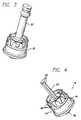
- FIG. 1is a perspective view of a medical connector that incorporates aspects of the present invention
- FIG. 2is an exploded perspective view of the medical connector shown in FIG. 1 depicting a valve body, a male Luer lock insert, and a flex-tube assembly, i.e., valve assembly, including a flex-tube piston and a flex-tube insert;
- a flex-tube assemblyi.e., valve assembly, including a flex-tube piston and a flex-tube insert;
- FIG. 3is a perspective view of the medical connector shown in FIG. 1 with the valve body removed and depicting the flex-tube assembly positioned on the male Luer lock insert;
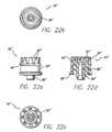
- FIG. 4is perspective view of the male Luer lock insert shown in FIGS. 1–3 ;
- FIGS. 5 a – 5 ddepict various views of the male Luer-lock insert shown in FIG. 4 including a side elevation view, a top plan view, a bottom plan view and a full sectional view;
- FIG. 6is a perspective view of the valve body shown in FIG. 1 ;
- FIGS. 7 a – 7 ddepict various views of the valve body shown in FIGS. 2 and 6 including a side elevation view, a top plan view, a bottom plan view and a full sectional view;
- FIG. 8 ais a full sectional view of the flex-tube assembly shown in FIGS. 2 and 3 depicted in an uncompressed state and showing the flex-tube insert positioned within the flex-tube piston;
- FIG. 8 bis a top view of the flex-tube assembly shown in FIG. 8 a taken along the line 8 b — 8 b;
- FIG. 9 ais a full sectional view of the flex-tube assembly shown in FIGS. 2 and 3 depicted in a compressed state and showing the flex-tube insert positioned within the flex-tube piston;
- FIG. 9 bis a top view of the flex-tube assembly shown in FIG. 9 a taken along the line 9 b — 9 b;
- FIG. 10is a perspective view of the flex-tube insert shown in FIGS. 2 , 8 a , 8 b , 9 a , and 9 b;
- FIG. 11 ais a side elevation view and a top view of the flex-tube insert shown in FIG. 10 ;
- FIG. 11 bis a full sectional view of the flex-tube insert shown in FIG. 10 ;
- FIG. 12is a perspective view of the flex-tube piston shown in FIGS. 2 , 3 , 8 a and 8 b;
- FIGS. 13 a and 13 bare first and second full sectional views and top views of the flex-tube piston shown in FIG. 12 with the views rotated 90 degrees from each other;
- FIG. 14is a full sectional view of a positive-bolus configuration of the medical connector shown in FIG. 1 depicting the flex-tube assembly in the uncompressed state;
- FIG. 15is a full sectional view of a positive-bolus configuration of the medical connector shown in FIG. 1 depicting the flex-tube assembly in the compressed state under pressure of an inserted blunt or needle-free cannula having a male Luer taper;
- FIG. 15 ais a graph depicting the volume of fluid within the flex-tube assembly as a function of the depth of insertion of a blunt or needle-free cannula into a medical connector providing a positive-bolus effect;
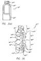
- FIG. 16is an elevation view of another medical connector that incorporates aspects of the present invention.
- FIG. 17 ais a full sectional view of a flex-tube assembly incorporated in the connector shown in FIG. 16 depicted in an uncompressed state and showing the flex-tube insert positioned within and surrounded by the flex-tube piston;
- FIG. 17 bis a top view of the flex-tube assembly shown in FIG. 17 a taken along the line 17 b — 17 b;
- FIG. 18 ais a full sectional view of the flex-tube assembly incorporated in the connector shown in FIG. 16 depicted in a compressed state and showing the flex-tube insert positioned within and surrounded by the flex-tube piston;
- FIG. 18 bis a top view of the flex-tube assembly shown in FIG. 18 a taken along the line 18 b — 18 b;
- FIG. 19is a full sectional view of the medical connector shown in FIG. 16 depicting the flex-tube assembly in the uncompressed state;
- FIG. 20is a full sectional view of the medical connector shown in FIG. 16 depicting the flex-tube assembly in the compressed state;
- FIG. 21is an elevation view of another medical connector that incorporates aspects of the present invention.
- FIG. 21 ais an exploded perspective view of the medical connector shown in FIG. 21 depicting a valve body, a male Luer lock insert, and a one-piece flex-tube assembly, i.e., valve assembly;
- FIGS. 22 a – 22 ddepict various views of the male Luer-lock insert shown in FIG. 21 including a side elevation view, a top plan view, a bottom plan view and a full sectional view;
- FIG. 23is a perspective view of the valve body shown in FIG. 21 ;
- FIGS. 24 a – 24 ddepict various views of the valve body shown in FIG. 23 including a side elevation view, a top plan view, a bottom plan view and a full sectional view;
- FIGS. 25 a and 25 bare perspective views of the flex-tube assembly housed within the medical connector shown in FIG. 21 , FIG. 25 a depicts the flex-tube assembly in an uncompressed state while FIG. 25 b depicts it in a compressed state;
- FIG. 26 a and 26 bare first and second full sectional views and top views of the flex-tube assembly shown in FIG. 25 with the views rotated 90 degrees from each other;
- FIG. 27 ais a full sectional view of the flex-tube assembly shown in FIG. 25 depicted in an uncompressed state;
- FIG. 27 bis a top view of the flex-tube assembly shown in FIG. 27 a taken along the line 27 b — 27 b;
- FIG. 28 ais a full sectional view of the flex-tube assembly shown in FIG. 25 depicted in an compressed state
- FIG. 28 bis a top view of the flex-tube assembly of FIG. 28 a taken along the line 28 b — 28 b;
- FIG. 29is a full sectional view of a positive-bolus configuration of the medical connector of FIG. 21 depicting the flex-tube assembly in the uncompressed state;
- FIG. 30is a full sectional view of a positive-bolus configuration of the medical connector of FIG. 21 depicting the flex-tube assembly in the compressed state under pressure of an inserted blunt or needle-free cannula having a male Luer taper;
- FIG. 31is an exploded perspective view of a medical connector that incorporates aspects of the present invention, depicting a valve body, a male Luer-lock insert, and a one-piece flex-tube assembly, i.e., valve assembly;
- FIG. 32is a perspective view of the male Luer-lock insert shown in FIG. 31 ;
- FIGS. 33 a – 33 cdepict various views of the male Luer-lock insert shown in FIG. 32 , including a side elevation view, a top plan view, and a full sectional view;
- FIG. 34is a perspective view of the valve body shown in FIG. 31 ;
- FIGS. 35 a – 35 ddepict various views of the valve body shown in FIG. 34 , including a first side elevation view, a top plan view, a full sectional view and a second side elevation view rotated 90 degrees relative the first side elevation view;
- FIG. 36is a perspective view of the flex-tube assembly in FIG. 31 , depicting the flex-tube assembly in an uncompressed state;
- FIGS. 37 a – 37 bare first and second full sectional views and top views of the flex-tube assembly shown in FIG. 36 with the views rotated 90 degrees from each other;
- FIG. 38 ais a full sectional view of the flex-tube assembly shown in FIG. 36 depicted in an uncompressed state;
- FIG. 38 bis a top view of the flex-tube assembly shown in FIG. 38 a taken along the line 38 b — 38 b;
- FIG. 39 ais a full sectional view of the flex-tube assembly shown in FIG. 36 depicted in an compressed state.
- FIG. 39 bis a top view of the flex-tube assembly of FIG. 39 a taken along the line 39 b — 39 b.
- FIGS. 1 , 16 and 21there is illustrated in FIGS. 1 , 16 and 21 several medical connectors that include a needleless valve embodying aspects of the invention. These particular connector configurations are for illustration purposes only.
- the subject needleless valvecan be embodied in any of a variety of connectors including, but not limited to, Y-connectors, J-loops, T-Connectors, Tri-connectors, PRN adapters, slip Luers, tubing engagement devices, access pins, vail adapters, blood tube adapters, bag access pins, and vented adapters.
- the connector 10comprises a valve body 12 having an inlet port 14 .
- the connector 10further includes a male Luer-lock insert 16 terminating in an outlet port 18 .
- the valve body 12 and the male Luer-lock insertform a connector housing.
- the portion of the valve body 12 near the inlet port 14includes a Luer adapter 20 .
- the adapter 20is configured to receive all ANSI standard male Luer fittings, as well as other blunt cannulas or fluid conduit devices.
- the connector 10also includes a resiliently deformable flex-tube assembly 22 , i.e., valve assembly, which includes a flex-tube insert 24 disposed within a flex-tube piston 26 . As shown in FIGS.
- the male Luer-lock insert 16includes a support post 28 for receiving the flex-tube assembly 22 .
- the support post 28has three vertical channels 30 running the length of the post and terminating at the proximal end of the tubular-housing fluid path 32 .
- the male Luer-lock insert 16includes a tubular housing 34 having a circular cross-section. Extending upward from the center of the tubular housing 34 is the support post 28 . Extending downward from the center of the tubular housing 34 is a male-Luer taper 36 .
- the tubular housing 34includes an outer shroud 38 and an inner shroud 40 . The outer shroud 38 surrounds the base of the support post 28 and most of the male-Luer taper 36 .
- the portion of the outer shroud 38 surrounding the male-Luer taper 36is internally threaded.
- the inner shroud 40also surrounds the base of the support post 28 .
- the space between the base of the support post 28 and the inner shroud 40forms an annular groove 42 .
- the annular groove 42is used to secure the base of the flex-tube assembly 22 .
- the exterior surface of the tubular housing 34 of the Luer-lock insert 16is molded to include a crown shaped outer shell 44 which includes several crown points 46 .
- the interior of the valve body 12is molded to include a crown shaped inner shell 48 which includes several crown points 50 .
- the crowned tubular-housing outer shell 44 of the Luer-lock insert 16mates with the crowned valve-body inner shell 48 of the valve body 12 , thereby facilitating snap-fit assembly of the medical connector.
- the male Luer-lock insert 16 and valve body 12may be joined by ultrasonic weld geometry, a spin weld, bonding, or by other means.
- the interior of the valve body 12has sections of varying diameters.
- the section directly adjacent the inlet port 14includes a standard ANSI Luer taper section 52 that incorporates a very slight inward taper.
- the center section 54has a larger diameter than the taper section 52 and is separated from the taper section by the tapered ramp/lock section 56 .
- the bottom section 58has a larger diameter than the center section 54 and is separated from the center section by a taper section 60 .
- the valve body 12includes a skirt 62 .
- the skirt 62has an inside diameter that is dimensioned to fit over the male Luer-lock insert 16 .
- the valve body 12may be molded of a material containing a phosphorescent colorant to render the connector visible in a darkened room or may be formed of a transparent material.
- the resiliently deformable flex-tube assembly 22includes the flex-tube insert 24 and the flex-tube piston 26 .
- the flex-tube insert 24is surrounded by the flex-tube piston 26 .
- the flex-tube assembly 22is captured in the groove 42 of the male Luer-lock insert 16 to form a tight seal about the support post 28 and the top of the male Luer taper 36 .
- the flex-tube piston 26includes an-antimicrobial agent, such as silver, silver oxide or silver sulfadiazine. The agent may be included in the material forming the flex-tube piston or may be added to the outer surface of the piston as a coating.
- the flex-tube insert 24 , valve body 12 and/or male Luer-lock 16 insertmay also include an antimicrobial agent.
- the peripheral surface of the flex-tube piston 26is also lubricated with FDA approved silicone oil to facilitate movement of the flex-tube assembly within the connector.
- the flex-tube insert 24includes an annular inlet support 64 , an annular outlet support 66 and a middle support 68 . Positioned between adjacent supports is a collapsible section 70 .
- Each collapsible section 70includes four hinge assemblies 72 arranged in a square, as shown in FIG. 11 a .
- Each hinge assembly 72includes two plates 74 and a hinge 76 about which the plates pivot.
- the inner surfaces of the plates 74are sloped. As explained below, the sloped surfaces prevent the plates 74 from completely collapsing on each other.
- edges 78 of the plates parallel with the hinge 76are attached to one of the supports 64 , 66 , or 68 .
- the connection between the edges 78 and the supports 64 , 66 , or 68is facilitated by a support hinge 80 . Operation of the flex-tube insert 24 is described below in conjunction with the flex-tube piston 26 .
- the flex-tube piston 26includes a piston head 82 , an expandable section 84 and a piston base 86 .
- the piston head 82includes a top section 88 that is elliptical in cross-section and a bottom, thick taper-lock portion 90 that is circular in cross-section.
- the taper-lock portion 90includes an annular groove 92 that is sized to receive and secure the annular inlet support (not shown) of the flex-tube insert 24 .
- the base 86 of the flex-tube pistonalso includes an annular groove 94 that receives and secures the annular outlet support (not shown).
- a marquise-shaped bore 96is formed in the piston head 82 .
- the top portion 88 of the piston head 82includes a lip seal 98 that comprises a pair of lips 100 that extend from opposed sides of the bore 96 to function as a seal.
- the bore 96in conjunction with the hollow interior of the taper lock section 90 and the hollow interior of the expandable section 84 , form a fluid path 102 through the flex-tube piston 26
- the piston head 82 and bore 96are configured closeup and function similarly to the piston head and bore described in U.S. Pat. No. 5,676,346, inventor Karl R. Leinsing, entitled NEEDLELESS CONNECTOR VALVE, and assigned to the same assignee of record of this application, the disclosure of which is hereby incorporated by reference.
- the flex-tube insert 24( FIG. 11 a ) is able to facilitate expansion of the fluid-flow path 102 ( FIGS. 8 a and 9 a ) of flex-tube piston 26 to either increase the volumetric capacity of the fluid flow path to provide a positive-bolus effect, or to maintain it at a substantially constant capacity to provide a no-bolus effect.
- the flex-tube assembly 22may also be designed to provide a negative-bolus effect.
- the flex-tube piston 26is designed to provide a restoring force to the flex-tube insert 24 ( FIG.
- the flex-tube piston 26is molded of a resilient flexible rubber material such as silicone, while the flex-tube insert 24 is formed of a more rigid material, such as material polyethylene.
- the flex-tube assembly 22is movable between an uncompressed state ( FIG. 8 a ) and a compressed state ( FIG. 8 b ).
- the flex-tube insert 24In the uncompressed state the flex-tube insert 24 has a first maximum width 104 , as shown in FIG. 8 b , and the fluid path 102 defined by the flex-tube piston 26 has a first internal volume.
- the flex-tube insert 24In the compressed state the flex-tube insert 24 has a second maximum width 106 greater than the first maximum width 104 , as shown in FIG. 9 b , and the fluid path 102 defined by the flex-tube piston 26 has a second internal volume greater than or substantially equal to the first internal volume.
- the second internal volumewhen the second internal volume is greater than the first internal volume a positive-bolus effect is provided.
- the second internal volumeWhen the second internal volume is substantially equal to the first internal volume a no-bolus effect is provided.
- the interplay between the flex-tube insert 24 and the flex-tube piston 26facilitate the movement between the uncompressed and compressed states.
- the flex-tube insert 24is instrumental in establishing the compressed state.
- opposed hinges 76 of the flex-tube insert 24move away from each other and the respective plates 74 attached to these hinges collapse toward each other.
- the sloped inner surfaces of the plates 74limit the movement of the hinges and prevent the plates from completely collapsing on each other.
- the maximum cross section of the flex-tube insert 24increases and the expandible section 84 ( FIG. 13 a ) of the flex-tube piston 26 stretches.
- the dimensions of the top portion 88 of the piston head 82 and the marquise-shaped bore 96are selected such that when the top portion is constrained within the circular interior of the ANSI Luer taper section 52 the bore 96 is completely collapsed to tightly close off the orifice and cause the adjacent lips 100 to abut one another.
- the tapered shoulder 108 of the taper lock section 90contacts the ramp/lock section 56 of the valve body 12 and prevents the top portion 88 of the piston head 82 from extending beyond the inlet port 14 .
- the internal diameter of the center section 54 of the valve body 12is selected such that the top portion 88 of the piston head 82 is free to assume its elliptical shape when positioned therein. This, in turn, allows the bore 96 to reassume its natural marquise-shape thereby opening the fluid path 102 through the flex-tube assembly 22 .
- the connector 10In operation of a positive-bolus medical connector, the connector 10 is initially in its unaccessed state or closed position as shown in FIG. 14 .
- the resiliency of the expandable section 84 of the flex-tube piston 26causes the piston head 82 to be biased into the ANSI Luer taper section 52 .
- the shoulder 108 of the flex-tube piston 26contacts the tapered ramp/lock section 56 of the valve body 12 and prevents the top of the piston head 82 from extending beyond the edge of the inlet port 14 to form a smooth and flush surface.
- the bore 96 through the piston head 82is tightly squeezed shut by virtue of the normally elliptically shaped top portion 88 of the piston head being constrained into the circular cross-section of the ANSI Luer taper section 52 .
- the sharp pointed ends of the marquise-shaped bore 96facilitate a tight seal upon compression of the bore along its minor axis 110 ( FIG. 13 b ) and by compression of the top portion 88 of the piston head 82 along its major axis 112 .
- the top surface of the piston head 82 and the edge of the inlet port 14are cleaned by, for example, passing a sterilizing swipe over the smooth surface.
- the absence of ridges, grooves, gaps, or protrusionsensure that proper cleanliness is achieved.
- the connectoris then ready to be accessed by a standard male Luer with or without a Luer lock.
- a sealis formed to preclude the passage of liquid or air therebetween.
- the application of sufficient pressurecauses the collapsible sections 70 of the flex-tube insert 24 to collapse about the support post 28 and the expandable section 84 of the flex-tube piston 26 to expand.
- the support post 28serves to prevent the flex-tube insert 24 from buckling and closing off the fluid path.
- the piston head 82moves out of the ANSI Luer taper section 52 and into the center section 54 .
- the larger internal diameter of the center section 54allows the top portion 88 of the piston head to assume its naturally elliptical open shape. This, in turn, allows the bore 96 to assume its natural marquise-shape thereby opening a fluid path through the piston head.
- the male Luer tip 114causes the bottom of the piston head 82 to communicate with the top of the support post 28 . Fluid flows through the bore 96 , into the hollow interior of the piston head 82 , along the channels 30 formed on the outside of the support post 28 into the expanded areas 122 of the fluid flow path 102 and then into the tubular-housing fluid path 32 .
- the flex-tube assembly 22compresses it expands and the fluid capacity of the fluid path 102 increases, thus the volume of fluid within the connector is greater during activation of the valve. Because the internal volume increases during actuation, thereby producing a partial vacuum, fluid may be drawn toward the outlet port of the connector, for example blood from a patient may be drawn into an IV line. The drawing of fluid at this time is beneficial in that it provides a patency check of the IV line and ensures that infusion may proceed.
- the restoring force generated by the expandable section 84 of the flex-tube piston 26causes the collapsed sections 70 of the flex-tube insert 24 to return to a noncollapsed state ( FIG. 14 ) and the fluid capacity of the fluid path 102 decreases.
- the elliptical top portion 88 of the piston head 82is guided into the ANSI Luer taper section 52 by the tapered ramp/lock section 56 where it is once again forced into the constrained circular shape of the ANSI Luer taper section to close off the bore 96 and reestablish a positive seal.
- the internal fluid capacity of the flex-tube assembly 22decreases, the fluid contained therein is displaced.
- volumetric increase of the fluid path 102 during depression of the flex-tube assembly 22is dependent on the depth to which the male Luer tip 114 is inserted into the inlet port 14 .
- the volumetric capacity of the fluid pathincreases.
- the volumetric capacity of the fluid pathreaches a maximum value, beyond which the capacity begins to decrease toward a steady state. This steady state point is reached when the male Luer tip is at its maximum depth.
- the flex-tube assemblyis dimensioned such that the volumetric capacity of the fluid path 102 during deactuation, i.e., the priming volume, is approximately 0.089 milliliters (ml.). The maximum volumetric capacity during actuation is approximately 0.099 ml.
- the flex-tube insert 24includes two compressible sections 70 .
- the flex-tube insert 24may comprise more or fewer compressible sections 70 .
- the flex-tube insert 24has only one compressible section 70 .
- the valve body 12 and male Luer-lock insert 16are reconfigured to accommodate the increased second maximum cross section 106 of the flex-tube insert, as shown in FIG. 18 b .
- the remaining configurational and operational aspects of the connectors, including the operation of the connectorsare substantially identical.
- FIG. 21there is shown another configuration of a medical connector which incorporates aspects of the invention. Except for the flex-tube assembly, this configuration of the connector is generally similar to the connector of FIG. 1 . Accordingly, the description of this connector primarily centers around the flex-tube assembly.
- the numerals associated with elements of the second configurationare the same as those of the first configuration except they are primed. For numerals that are not primed there is no correlating element in the first configuration.
- the connector 10 ′comprises a valve body 12 ′, a male Luer-lock insert 16 ′ and a flex-tube assembly 22 ′.
- the male Luer-lock insert 16 ′is substantially identical to the male Luer-lock insert 16 ( FIG. 5 a ) of the first configuration, except there is no support post 28 .
- the valve body 12 ′is also substantially similar to the first configuration except that the tapered section 60 ′, as shown in FIGS. 24 a – 24 d , is slightly different to accommodate for the different design of the flex-tube assembly 22 ′.
- the flex-tube assembly 22 ′is formed as one piece. At the inlet end of the flex-tube assembly 22 ′ is an elliptical piston head 82 ′. As is shown in FIG. 29 the base 86 ′ is captured in the groove 42 ′ between the proximal end of the male Luer taper 36 ′ and the inner shroud 40 ′ of the male Luer-lock insert 16 ′ to form a tight seal about the top of the male Luer taper.
- the flex-tube assembly 22 ′is coated and lubricated in the same manner as previously described for the first configuration of the connector.
- the flex-tube assembly 22 ′is molded of a resilient flexible rubber material, such as silicone, having various thicknesses at different regions to provide functionality to the assembly. As shown in FIGS. 26 a and 26 b , the flex-tube assembly 22 ′ includes an elliptical piston head 82 ′ similar to that of the flex-tube piston of the other configuration. The flex-tube assembly 22 ′ also includes a piston base 86 ′ and a middle support 68 ′. Positioned between the piston head 82 ′ and the middle support 68 ′ is a collapsible/expandable section 70 ′.
- a resilient flexible rubber materialsuch as silicone
- Each collapsible/expandable section 70 ′includes three hinge assemblies 72 ′ arranged in a triangle, as shown in FIG. 27 a .
- Each hinge assembly 72 ′includes two triangular plates 74 ′ and a hinge 76 ′ about which the plates pivot.
- the edges 78 ′ ( FIG. 26 b ) of the plates parallel with the hinge 76 ′are attached to one of either the bottom of the piston head 82 ′, the piston base 86 ′ or the middle support 68 ′.
- the connection of the plate edges 78 ′ to the piston head 82 ′ and piston base 86 ′is facilitated by a head/base hinge 80 ′.
- the edges 118 of the hinge assemblies 72 ′ perpendicular to the hinges 76 ′are joined to the edges of adjacent hinge assemblies by thin webs 120 .
- the entire flex-tube assembly 22 ′is formed from the same mold, thus the webs 120 are made of the same material as the hinge assemblies 72 ′ but are thinner than the hinge assemblies.
- the thickest region of the hinge assembly plates 74 ′may be approximately 0.090 inches and the hinges 76 ′ approximately 0.015 inches, while the thickness of the webs 120 may be approximately 0.010 inches. This difference allows for expansion of the collapsible/expandable section.
- the thickness and positioning of the hinge assemblies 72 ′ of the flex-tube assembly 22 ′are designed to facilitate the expansion of the flex-tube assembly to either increase the volumetric fluid capacity of the fluid flow path 102 ′ to provide a positive-bolus effect, or to maintain it at a substantially constant capacity to provide a no-bolus effect. If desired, the flex-tube assembly 22 ′ may also be designed to provide a negative-bolus effect.
- the thickness and relative positioning of the hinge assemblies 72 ′ and the webs 120in turn are designed to provide a restoring force to the flex-tube assembly 22 ′ to compress the flex-tube assembly and thus return the volumetric fluid capacity of the fluid flow path 102 ′ to its original value.
- the flex-tube assembly 22 ′is movable between an uncompressed state ( FIG. 27 a ) and a compressed state ( FIG. 28 a ).
- the flex-tube assembly 22 ′In the uncompressed state the flex-tube assembly 22 ′ has a first maximum cross-sectional area 104 ′, as shown in FIG. 27 b , and the fluid path 102 ′ defined by the flex-tube assembly 22 ′ has a first internal volume.
- the flex-tube assembly 22 ′In the compressed state the flex-tube assembly 22 ′ has a second maximum cross-sectional area 106 ′ greater than the first maximum cross sectional area 104 ′, as shown in FIG.
- the fluid path 102 ′ defined by the flex-tube assembly 22 ′has a second internal volume greater than or substantially equal to the first internal volume.
- the varying thicknesses of the flex-tube assembly 22 ′facilitates the movement between the uncompressed and compressed states.
- the thick hinge assemblies 72 ′ of the flex-tube assembly 22 ′are instrumental in establishing the compressed state.
- the hinges 76 ′move outward and the respective plates 74 ′ attached to these hinges collapse toward each other.
- the plates 74 ′collapse the webs 120 stretch. For a positive-bolus connector this increases the internal volume of the fluid path 102 ′ toward a second internal volume greater than the first internal volume.
- the flex-tube assembly 22 ′When the application of downward force is removed, the resiliency of the hinge assemblies 72 ′ and the webs 120 force the hinges 76 ′ inward and the plates 74 ′ apart. Thus the flex-tube assembly 22 ′ returns to its original uncompressed state and for a positive-bolus connector, the internal volume of the fluid path 102 ′ decreases. For a no-bolus connector, the internal volume remains substantially constant as the flex-tube assembly 22 ′ moves between compressed and uncompressed states.
- the connector 10 ′is initially in its inactive state or closed position as shown in FIG. 29 .
- the flex-tube assembly 22 ′is pre-loaded and causes the piston head 82 ′ to be biased into the ANSI Luer taper section 52 ′.
- the top hinge plates 74 ′ of the flex-tube assembly 22 ′contacts the taper section 60 ′ of the valve body 12 ′ and prevents the top portion 88 ′ of the piston head 82 ′ from extending beyond the edge of the inlet port 14 ′ to form a smooth and flush surface.
- the bore 96 ′ through the piston head 82 ′is tightly squeezed shut by virtue of the normally elliptically shaped top portion 88 ′ of the piston head being constrained into the circular cross-section of the ANSI Luer taper section 52 ′.
- the sharp pointed ends of the marquise-shaped bore 96 ′facilitate a tight seal upon compression of the bore along its minor axis 110 ′ ( FIG. 26 b ) and compression of the piston head 82 ′ along its major axis 112 ′.
- the collapsible sections 70 ′ of the flex-tube assembly 22 ′collapse and expand.
- the maximum diameters of the middle support 68 ′ and collapsible sections 70 ′are sized approximately equal to the diameter of the valve body 12 ′.
- the larger internal diameter of the taper section 60 ′allows the top portion 88 ′ of the piston head to assume its naturally elliptical open shape. This, in turn, allows the bore 96 ′ to assume its natural marquise-shape thereby opening a fluid path through the piston head 82 ′. In this condition the connector is in an active state or an open piston. Fluid flows through the bore 96 ′, into the hollow interior of the piston head 82 ′, through the interior of the flex-tube assembly 22 ′ and into the tubular-housing fluid path 32 ′.
- the elliptical top portion 88 ′ of the piston head 82 ′is guided into the ANSI Luer taper section 52 ′ by the tapered ramp/lock section 56 ′ where it is once again forced into the constrained circular shape of the ANSI Luer taper section to close off the bore 96 ′ and reestablish a positive seal.
- the internal fluid capacity of the flex-tube assembly 22 ′decreases the fluid contained therein is displaced. Because the bore 96 ′ has established a positive seal at the inlet port 14 ′, the fluid is displaced toward the outlet port 18 ′. The displacement of fluid toward the outlet port 18 ′ prevents a negative-bolus effect.
- the volumetric increase of the fluid path 102 ′ during depression of the flex-tube assembly 22 ′is dependent on the depth to which the male Luer tip 114 ′ is inserted into the inlet port 14 ′.
- the flex-tube assemblyis dimensioned such that the volumetric capacity of the fluid path 102 ′ during deactuation, i.e., the priming volume, is 0.105 ml. The maximum volumetric capacity during actuation is greater than the priming volume.
- FIG. 31there is shown another configuration of a medical connector which incorporates aspects of the invention. Except for the flex-tube assembly and the valve body, this configuration of the connector is generally similar to the connector of FIG. 21 . Accordingly, the description of this connector primarily centers around the flex-tube assembly and the valve body. For ease in correlating the two configurations, the numerals associated with elements of the third configuration are the same as those of the second configuration, except they are double primed.
- the connector 10 ′′comprises a valve body 12 ′′, a male Luer-lock insert 16 ′′, and flex-tube assembly 22 ′′.
- the male Luer-lock insert 16 ′′is substantially identical to the male Luer-lock insert 16 ′ ( FIGS. 22 a – 22 d ) of the second configuration.
- the valve body 12 ′′is also substantially similar to the valve body 12 ′ ( FIGS. 23–24 d ) of the second configuration, except that a proportion of the tubular valve body is flattened to accommodate for the rectangular design of the flex-tube assembly 22 ′′.
- FIGS. 32–33 cthe male Luer-lock insert 16 ′′ is substantially identical to the male Luer-lock insert 16 ′ ( FIGS. 22 a – 22 d ) of the second configuration.
- the valve body 12 ′′is also substantially similar to the valve body 12 ′ ( FIGS. 23–24 d ) of the second configuration, except that a proportion of the tubular valve body is flattened to accommodate for
- the flex-tube assembly 22 ′′is formed similarly to the flex-tube assembly 22 ′ ( FIGS. 25 a – 26 b ) of the second configuration.
- the elliptical piston head 82 ′′At the inlet end of the flex-tube assembly 22 ′′ is the elliptical piston head 82 ′′.
- the base 86 ′′is captured in the groove 42 ′′ ( FIG. 33 c ) to form a tight seal about the top of the male-Luer taper 36 ′′.
- the flex-tube assembly 22 ′′is coated and lubricated as previously described for the second configuration.
- the flex-tube assembly 22 ′′ of the third configurationincludes a pair of collapsible/expandable sections 70 ′′.
- Each collapsible/expandable section 70 ′′includes a pair of opposed hinge assemblies 72 ′′.
- Each hinge assembly 72 ′′includes two triangular plates 74 ′′ and a hinge 76 ′′ about which the plates pivot.
- the hinge-assemblies 72 ′′include beveled edges 118 ′′.
- the beveled edges 118 ′′ perpendicular to the hinges 76 ′′are joined to the edges of the opposite hinge assembly by a thin web 120 ′′.
- the flex-tube assembly 22 ′′is movable between an uncompressed state ( FIG. 38 a ) and a compressed state ( FIG. 39 a ).
- the flex-tube assembly 22 ′′has a first maximum internal cross-sectional area 104 ′′, as shown in FIG. 38 b
- the fluid path 102 ′′ defined by the flex-tube assembly 22 ′′has a first internal volume.
- the flex-tube assembly 22 ′′has a second maximum internal cross-sectional area 106 ′′ greater than the first maximum internal cross sectional area 104 ′′, as shown in FIG. 39 b , and the fluid path 102 ′′ defined by the flex-tube assembly 22 ′′ has a second internal volume greater than or substantially equal to the first internal volume.
- the hinges 76 ′′move outward and the respective plates 74 ′′ attached to these hinges collapse toward each other.
- the bevels 118 ′′flatten out and the webs 120 ′′ stretch, and for a positive-bolus connector, there is an increase in the internal volume of the fluid path 102 ′′.
- the internal volumeremains substantially constant.
- the resiliency of the hinge assemblies 72 ′′ and the webs 120 ′′force the hinges 76 ′′ inward and the plates 74 ′′ apart.
- the flex-tube assembly 22 ′′returns to its original uncompressed state.
- the flex tube assembly 22 ′′ of the third configurationis substantially identical to the flex-tube assembly 22 ′ of the second configuration.
- the flex-tube assemblies 22 ′, 22 ′′function in substantially identical ways. Accordingly, a description of the detailed operation of the third configuration may be had by reference to the preceding description of the detailed operation of the second configuration.
Landscapes
- Health & Medical Sciences (AREA)
- Heart & Thoracic Surgery (AREA)
- Pulmonology (AREA)
- Engineering & Computer Science (AREA)
- Anesthesiology (AREA)
- Biomedical Technology (AREA)
- Hematology (AREA)
- Life Sciences & Earth Sciences (AREA)
- Animal Behavior & Ethology (AREA)
- General Health & Medical Sciences (AREA)
- Public Health (AREA)
- Veterinary Medicine (AREA)
- Infusion, Injection, And Reservoir Apparatuses (AREA)
- Apparatus For Disinfection Or Sterilisation (AREA)
- Pharmaceuticals Containing Other Organic And Inorganic Compounds (AREA)
Abstract
Description
Claims (28)
Priority Applications (1)
| Application Number | Priority Date | Filing Date | Title |
|---|---|---|---|
| US10/143,619US7184825B2 (en) | 1999-07-27 | 2002-05-08 | Needless medical connector having antimicrobial agent |
Applications Claiming Priority (2)
| Application Number | Priority Date | Filing Date | Title |
|---|---|---|---|
| US09/361,543US6706022B1 (en) | 1999-07-27 | 1999-07-27 | Needleless medical connector with expandable valve mechanism |
| US10/143,619US7184825B2 (en) | 1999-07-27 | 2002-05-08 | Needless medical connector having antimicrobial agent |
Related Parent Applications (1)
| Application Number | Title | Priority Date | Filing Date |
|---|---|---|---|
| US09/361,543DivisionUS6706022B1 (en) | 1999-07-27 | 1999-07-27 | Needleless medical connector with expandable valve mechanism |
Publications (2)
| Publication Number | Publication Date |
|---|---|
| US20020133124A1 US20020133124A1 (en) | 2002-09-19 |
| US7184825B2true US7184825B2 (en) | 2007-02-27 |
Family
ID=23422464
Family Applications (3)
| Application Number | Title | Priority Date | Filing Date |
|---|---|---|---|
| US09/361,543Expired - LifetimeUS6706022B1 (en) | 1999-07-27 | 1999-07-27 | Needleless medical connector with expandable valve mechanism |
| US10/143,619Expired - LifetimeUS7184825B2 (en) | 1999-07-27 | 2002-05-08 | Needless medical connector having antimicrobial agent |
| US10/426,737Expired - LifetimeUS7497848B2 (en) | 1999-07-27 | 2003-04-30 | Needleless medical connector with expandable valve mechanism |
Family Applications Before (1)
| Application Number | Title | Priority Date | Filing Date |
|---|---|---|---|
| US09/361,543Expired - LifetimeUS6706022B1 (en) | 1999-07-27 | 1999-07-27 | Needleless medical connector with expandable valve mechanism |
Family Applications After (1)
| Application Number | Title | Priority Date | Filing Date |
|---|---|---|---|
| US10/426,737Expired - LifetimeUS7497848B2 (en) | 1999-07-27 | 2003-04-30 | Needleless medical connector with expandable valve mechanism |
Country Status (13)
| Country | Link |
|---|---|
| US (3) | US6706022B1 (en) |
| EP (2) | EP1200153B1 (en) |
| JP (2) | JP4679016B2 (en) |
| AT (2) | ATE293474T1 (en) |
| AU (1) | AU6236000A (en) |
| CA (3) | CA2379943C (en) |
| CY (1) | CY1109589T1 (en) |
| DE (2) | DE60019605T2 (en) |
| DK (2) | DK1200153T3 (en) |
| ES (2) | ES2240125T3 (en) |
| HK (1) | HK1046248B (en) |
| PT (2) | PT1200153E (en) |
| WO (1) | WO2001007102A2 (en) |
Cited By (70)
| Publication number | Priority date | Publication date | Assignee | Title |
|---|---|---|---|---|
| US20020013556A1 (en)* | 1996-11-18 | 2002-01-31 | Cote Andrew L. | Swabbable luer-activated valve |
| US20030199835A1 (en)* | 1999-07-27 | 2003-10-23 | Leinsing Karl R. | Needleless medical connector with expandable valve mechanism |
| US20050038397A1 (en)* | 2003-07-31 | 2005-02-17 | Newton Brian L. | Anti-drawback medical valve |
| US20050131477A1 (en)* | 2003-12-12 | 2005-06-16 | Meyer Scott A. | Cardiac response classification using retriggerable classification windows |
| US20050288600A1 (en)* | 2004-06-24 | 2005-12-29 | Yi Zhang | Automatic orientation determination for ECG measurements using multiple electrodes |
| US20060027270A1 (en)* | 2004-08-09 | 2006-02-09 | Truitt Tim L | Connector with check valve and method of use |
| US20060116593A1 (en)* | 2004-11-30 | 2006-06-01 | Yi Zhang | Cardiac activation sequence monitoring for ischemia detection |
| US20060163515A1 (en)* | 2003-06-17 | 2006-07-27 | Ruschke Ricky R | Fluid handling device and method of making same |
| US20060200086A1 (en)* | 1995-12-15 | 2006-09-07 | Lopez George A | Medical valve with fluid escape space |
| US20060293629A1 (en)* | 2001-11-13 | 2006-12-28 | Cote Andrew L Sr | Anti-drawback medical valve |
| US20070219483A1 (en)* | 2006-03-17 | 2007-09-20 | Tyco Healthcare Group Lp | Connector |
| US20070235674A1 (en)* | 2006-04-11 | 2007-10-11 | Vangsness Todd S | Medical valve with rotating member and method |
| US20080004665A1 (en)* | 2006-06-29 | 2008-01-03 | Mccabe Aaron R | Determination of cardiac pacing parameters based on non-localized sensing |
| US20080009909A1 (en)* | 2006-06-29 | 2008-01-10 | Sathaye Alok S | Local and non-local sensing for cardiac pacing |
| US20080027398A1 (en)* | 2006-07-28 | 2008-01-31 | Becton, Dickinson And Company | Vascular access device volume displacement |
| US20080039802A1 (en)* | 2006-08-11 | 2008-02-14 | Nypro Inc. | Medical Valve With Expandable Member |
| US20080071318A1 (en)* | 2006-09-14 | 2008-03-20 | Brooke M Jason | Therapeutic electrical stimulation that avoids undesirable activation |
| US20080097407A1 (en)* | 2006-10-18 | 2008-04-24 | Michael Plishka | Luer activated device with compressible valve element |
| US20080108973A1 (en)* | 2006-11-02 | 2008-05-08 | Becton, Dickinson And Company | Vascular access device gas displacement |
| US20080172003A1 (en)* | 2006-10-18 | 2008-07-17 | Michael Plishka | Luer activated device |
| US20080172005A1 (en)* | 2006-10-18 | 2008-07-17 | Jepson Steven C | Luer activated device with valve element under tension |
| US20080275522A1 (en)* | 2003-12-11 | 2008-11-06 | Yanting Dong | Non-captured intrinsic discrimination in cardiac pacing response classification |
| US20080294215A1 (en)* | 2005-04-26 | 2008-11-27 | Sathaye Alok S | Implantable cardiac device for reduced phrenic nerve stimulation |
| US20090198301A1 (en)* | 2005-05-09 | 2009-08-06 | Yi Zhang | Automatic Capture Verification using Electrocardiograms Sensed from Multiple Implanted Electrodes |
| US20090204080A1 (en)* | 2008-02-12 | 2009-08-13 | Baxter International Inc. | Two-way valve connector |
| US20100030164A1 (en)* | 2008-08-04 | 2010-02-04 | Np Medical Inc. | Medical Valve with Raised Seal |
| US7753338B2 (en) | 2006-10-23 | 2010-07-13 | Baxter International Inc. | Luer activated device with minimal fluid displacement |
| US20100249724A1 (en)* | 2009-03-30 | 2010-09-30 | Np Medical Inc. | Medical Valve with Distal Seal Actuator |
| US20100308251A1 (en)* | 2006-11-17 | 2010-12-09 | Pascal Benjamin J | Needleless access port valves |
| US20110028914A1 (en)* | 2009-07-30 | 2011-02-03 | Medegen, Inc. | Collapsible Valve |
| US20110054440A1 (en)* | 2009-09-02 | 2011-03-03 | Carefusion 303, Inc. | Disinfecting male luer connector caps |
| US7917196B2 (en) | 2005-05-09 | 2011-03-29 | Cardiac Pacemakers, Inc. | Arrhythmia discrimination using electrocardiograms sensed from multiple implanted electrodes |
| USD644731S1 (en) | 2010-03-23 | 2011-09-06 | Icu Medical, Inc. | Medical connector |
| US8105314B2 (en) | 2006-10-25 | 2012-01-31 | Icu Medical, Inc. | Medical connector |
| US8177772B2 (en) | 2005-09-26 | 2012-05-15 | C. R. Bard, Inc. | Catheter connection systems |
| US8265736B2 (en) | 2007-08-07 | 2012-09-11 | Cardiac Pacemakers, Inc. | Method and apparatus to perform electrode combination selection |
| US8337475B2 (en) | 2004-10-12 | 2012-12-25 | C. R. Bard, Inc. | Corporeal drainage system |
| US8444628B2 (en) | 2000-07-11 | 2013-05-21 | Icu Medical, Inc. | Needleless medical connector |
| US8454579B2 (en) | 2009-03-25 | 2013-06-04 | Icu Medical, Inc. | Medical connector with automatic valves and volume regulator |
| US8506538B2 (en) | 2007-12-05 | 2013-08-13 | Covidien Lp | Device for reducing microbial contamination |
| US8568371B2 (en) | 2009-06-22 | 2013-10-29 | Np Medical Inc. | Medical valve with improved back-pressure sealing |
| US8628516B2 (en) | 2009-03-22 | 2014-01-14 | Elcam Medical Agricultural Cooperative Association Ltd. | Closed male luer connector |
| US8636721B2 (en) | 2003-11-20 | 2014-01-28 | Henry M. Jackson Foundation For The Advancement Of Military Medicine, Inc. | Portable hand pump for evacuation of fluids |
| US8758306B2 (en) | 2010-05-17 | 2014-06-24 | Icu Medical, Inc. | Medical connectors and methods of use |
| US8784388B2 (en) | 2011-09-30 | 2014-07-22 | Becton, Dickinson And Company | Syringe with disinfecting tip feature |
| US8840577B1 (en) | 2013-03-14 | 2014-09-23 | Carefusion 303, Inc. | Needleless connector with flexible valve |
| EP2783719A1 (en) | 2013-03-20 | 2014-10-01 | Caesarea Medical Electronics Ltd. | Vented Luer cone connector |
| US9089682B2 (en) | 2013-03-14 | 2015-07-28 | Carefusion 303, Inc. | Needleless connector with support member |
| US9138572B2 (en) | 2010-06-24 | 2015-09-22 | Np Medical Inc. | Medical valve with fluid volume alteration |
| US9144672B2 (en) | 2013-03-13 | 2015-09-29 | Carefusion 303, Inc. | Needleless connector with compressible valve |
| US9186707B2 (en) | 2007-04-02 | 2015-11-17 | C. R. Bard, Inc. | Insert for a microbial scrubbing device |
| US9186494B2 (en) | 2004-11-05 | 2015-11-17 | Icu Medical, Inc. | Medical connector |
| US9192449B2 (en) | 2007-04-02 | 2015-11-24 | C. R. Bard, Inc. | Medical component scrubbing device with detachable cap |
| US9278205B2 (en) | 2013-03-13 | 2016-03-08 | Carefusion 303, Inc. | Collapsible valve with internal dimples |
| US9302090B2 (en) | 2012-07-25 | 2016-04-05 | Applied Medical Technology, Inc. | Photoluminescent coupling |
| US9370651B2 (en) | 2013-03-13 | 2016-06-21 | Carefusion 303, Inc. | Needleless connector with reduced trapped volume |
| US20160213911A1 (en)* | 2015-01-27 | 2016-07-28 | Becton, Dickinson And Company | Antimicrobial inserts for stopcock medical connectors |
| US20160279327A1 (en)* | 2011-09-02 | 2016-09-29 | Carefusion 303, Inc. | Port-flushing control valve |
| US20160296740A1 (en)* | 2015-04-08 | 2016-10-13 | Dale Medical Products, Inc. | Non-luer compatible administration port |
| US9533160B2 (en) | 2007-08-07 | 2017-01-03 | Cardiac Pacemakers, Inc. | Method and apparatus to perform electrode combination selection |
| USD786427S1 (en) | 2014-12-03 | 2017-05-09 | Icu Medical, Inc. | Fluid manifold |
| USD793551S1 (en) | 2014-12-03 | 2017-08-01 | Icu Medical, Inc. | Fluid manifold |
| US10149971B2 (en) | 2014-04-23 | 2018-12-11 | Becton, Dickinson And Company | Antimicrobial stopcock medical connector |
| US10369349B2 (en) | 2013-12-11 | 2019-08-06 | Icu Medical, Inc. | Medical fluid manifold |
| US10478607B2 (en) | 2004-08-09 | 2019-11-19 | Carefusion 303, Inc. | Connector for transferring fluid and method of use |
| US10792399B2 (en) | 2014-02-20 | 2020-10-06 | Becton, Dickinson And Company | Antimicrobial inserts for medical devices |
| US10792398B2 (en) | 2014-02-20 | 2020-10-06 | Becton, Dickinson And Company | Antimicrobial inserts for medical devices |
| US11344318B2 (en) | 2016-07-18 | 2022-05-31 | Merit Medical Systems, Inc. | Inflatable radial artery compression device |
| US12426864B2 (en) | 2021-06-18 | 2025-09-30 | Merit Medical Systems, Inc. | Hemostasis devices and methods of use |
| US12440661B2 (en) | 2022-05-18 | 2025-10-14 | Icu Medical, Inc. | Medical fluid transfer device |
Families Citing this family (199)
| Publication number | Priority date | Publication date | Assignee | Title |
|---|---|---|---|---|
| US11090444B2 (en)* | 2018-06-15 | 2021-08-17 | James T. Doubet | Syringe adapter for medication |
| US11337894B2 (en) | 2018-06-15 | 2022-05-24 | James T. Doubet | Syringe adapter for animal medication |
| CA2124822C (en)* | 1991-12-18 | 2007-07-03 | George A. Lopez | Medical valve |
| US6245048B1 (en)* | 1996-12-16 | 2001-06-12 | Icu Medical, Inc. | Medical valve with positive flow characteristics |
| WO1998026835A1 (en)* | 1996-12-16 | 1998-06-25 | Icu Medical, Inc. | Positive flow valve |
| US20090026660A1 (en)* | 2001-04-11 | 2009-01-29 | Helix Medical, Llc | Methods of making antimicrobial voice prothesis devices |
| WO2003018104A2 (en)* | 2001-08-22 | 2003-03-06 | Nypro, Inc. | Medical valve with expandable seal member |
| WO2003030987A1 (en)* | 2001-10-09 | 2003-04-17 | Nypro, Inc. | Medical valve and method of assembling the same |
| US6802490B2 (en)* | 2001-11-29 | 2004-10-12 | Alaris Medical Systems, Inc. | Needle free medical connector with expanded valve mechanism and method of fluid flow control |
| US6985870B2 (en) | 2002-01-11 | 2006-01-10 | Baxter International Inc. | Medication delivery system |
| US6651956B2 (en)* | 2002-01-31 | 2003-11-25 | Halkey-Roberts Corporation | Slit-type swabable valve |
| ITMI20020819A1 (en)* | 2002-04-18 | 2003-10-20 | Gambro Lundia Ab | CONNECTION ELEMENT AND CONNECTION DEVICE FOR MEDICAL USE PIPES |
| US7244249B2 (en)* | 2002-05-08 | 2007-07-17 | Cardinal Health 303, Inc. | Needle-free medical connector with expandable valve mechanism and method of fluid flow control |
| US7160272B1 (en) | 2002-05-31 | 2007-01-09 | Elcam Plastic | Y-site medical valve |
| JP4000125B2 (en)* | 2002-08-06 | 2007-10-31 | フカイ工業株式会社 | Syringe connection port |
| JP2004195016A (en)* | 2002-12-19 | 2004-07-15 | Top:Kk | Coupling device |
| JP4064422B2 (en) | 2003-01-09 | 2008-03-19 | フカイ工業株式会社 | Seal valve for medical device, connection port, mixed injection tube, infusion circuit connection device, and infusion circuit connection system |
| US6871838B2 (en)* | 2003-04-03 | 2005-03-29 | B. Braun Medical Inc. | Injection port valve |
| US7217258B2 (en) | 2003-05-02 | 2007-05-15 | Becton, Dickinson And Company | Controlled release structure for attaching medical devices |
| DE10348016B4 (en)* | 2003-10-15 | 2007-05-03 | Fresenius Kabi Deutschland Gmbh | Connector for medical fluid containing packaging and packaging for medical fluids |
| US20080009822A1 (en)* | 2003-12-18 | 2008-01-10 | Halkey-Roberts Corporation | Needleless access vial |
| US20050159724A1 (en)* | 2003-12-18 | 2005-07-21 | Enerson Jon R. | Needleless access vial |
| US7396051B2 (en) | 2005-01-14 | 2008-07-08 | Baxa Corporation | Swabable fluid connectors and fluid connector pairs |
| US7510545B2 (en) | 2005-02-09 | 2009-03-31 | B. Braun Medical Inc. | Needleless access port valves |
| US7114701B2 (en)* | 2005-03-02 | 2006-10-03 | B. Braun Medical, Inc. | Needleless access port valves |
| US20060200072A1 (en)* | 2005-03-02 | 2006-09-07 | Peppel Peter W | Needleless access port valves |
| US8100866B2 (en) | 2005-03-24 | 2012-01-24 | B. Braun Medical Inc. | Needleless access port valves |
| US7615035B2 (en)* | 2005-03-24 | 2009-11-10 | B. Braun Medical Inc. | Needleless access port valves |
| US7314061B2 (en) | 2005-03-25 | 2008-01-01 | B. Braun Medical Inc. | Needleless access port valves |
| US7648491B2 (en)* | 2005-05-13 | 2010-01-19 | Bob Rogers | Medical substance transfer system |
| US7682561B2 (en)* | 2005-05-19 | 2010-03-23 | Sage Products, Inc. | Needleless hub disinfection device and method |
| US20060286686A1 (en)* | 2005-06-15 | 2006-12-21 | Honeywell International, Inc. | Integrated light emitting diode displays using biofabrication |
| US7503908B2 (en)* | 2005-07-22 | 2009-03-17 | B. Braun Medical Inc. | Needleless access port valves |
| ITTO20050516A1 (en)* | 2005-07-25 | 2007-01-26 | Borla Ind | MEDICAL CONNECTOR |
| CA2625824C (en)* | 2005-10-30 | 2013-12-17 | Medimop Medical Projects Ltd | Needleless additive control valve |
| CA2634754A1 (en)* | 2005-12-29 | 2007-07-12 | Nmt Medical, Inc. | Syringe activated-valve for flushing a catheter and methods thereof |
| US7591449B2 (en)* | 2006-02-14 | 2009-09-22 | B. Braun Medical Inc. | Needleless access port valves |
| US9695953B2 (en)* | 2006-02-14 | 2017-07-04 | B. Braun Medical Inc. | Needleless access port valves |
| US9895526B2 (en) | 2006-03-08 | 2018-02-20 | Ivaxis, Llc | Anti-contamination cover for fluid connections |
| ITTO20060206A1 (en)* | 2006-03-17 | 2007-09-18 | Borla Ind | VALVE VALVE FOR MEDICAL LINES |
| US7867204B2 (en)* | 2006-05-04 | 2011-01-11 | B. Braun Medical Inc. | Needleless access port valves |
| US20070270756A1 (en)* | 2006-05-22 | 2007-11-22 | Peter Peppel | Needleless access port valves |
| US11229746B2 (en) | 2006-06-22 | 2022-01-25 | Excelsior Medical Corporation | Antiseptic cap |
| US20080033371A1 (en)* | 2006-06-26 | 2008-02-07 | Updegraff Debra K | Cover for catheter assembly |
| GB0614452D0 (en)* | 2006-07-20 | 2006-08-30 | Young Peter J | Connector system |
| US7780794B2 (en) | 2006-07-21 | 2010-08-24 | Ivera Medical Corporation | Medical implement cleaning device |
| US8197452B2 (en)* | 2006-07-28 | 2012-06-12 | Becton, Dickinson And Company | Vascular access device non-adhering surfaces |
| US8512294B2 (en)* | 2006-07-28 | 2013-08-20 | Becton, Dickinson And Company | Vascular access device antimicrobial materials and solutions |
| US20080027410A1 (en)* | 2006-07-28 | 2008-01-31 | Becton, Dickinson And Company | Vascular access device non-adhering membranes |
| US8062267B2 (en)* | 2006-10-05 | 2011-11-22 | Becton, Dickinson And Company | Vascular access device including a tear-resistant septum |
| JP4994775B2 (en) | 2006-10-12 | 2012-08-08 | 日本コヴィディエン株式会社 | Needle point protector |
| US20080128647A1 (en)* | 2006-12-05 | 2008-06-05 | Humitek, Inc. | Valves and valve assemblies for fluid ports |
| US20080128646A1 (en)* | 2006-12-05 | 2008-06-05 | Humitek, Inc. | Splines and caps for fluid ports |
| US9259284B2 (en) | 2007-02-12 | 2016-02-16 | 3M Innovative Properties Company | Female Luer connector disinfecting cap |
| EP2121080B1 (en) | 2007-02-26 | 2017-11-01 | CareFusion 303, Inc. | Automatic relay pump system |
| US8287513B2 (en)* | 2007-09-11 | 2012-10-16 | Carmel Pharma Ab | Piercing member protection device |
| CA2739661C (en)* | 2007-10-19 | 2016-08-02 | Infusion Innovations, Inc. | Devices and assemblies for controlling fluid flow |
| ITTO20080059A1 (en)* | 2008-01-29 | 2009-07-30 | Industrie Borla Spa | VALVE VALVE FOR MEDICAL LINES |
| US8251346B2 (en)* | 2008-03-04 | 2012-08-28 | Infusion Innovations, Inc. | Devices, assemblies, and methods for controlling fluid flow |
| CA2717754C (en) | 2008-03-04 | 2017-06-06 | Infusion Innovations, Inc. | Devices, assemblies, and methods for controlling fluid flow |
| WO2009140511A1 (en) | 2008-05-14 | 2009-11-19 | J&J Solutions, Inc. | Systems and methods for safe medicament transport |
| US9078992B2 (en) | 2008-10-27 | 2015-07-14 | Pursuit Vascular, Inc. | Medical device for applying antimicrobial to proximal end of catheter |
| US20100135949A1 (en) | 2008-12-01 | 2010-06-03 | Becton, Dickinson And Company | Antimicrobial compositions |
| US8864725B2 (en) | 2009-03-17 | 2014-10-21 | Baxter Corporation Englewood | Hazardous drug handling system, apparatus and method |
| USD634007S1 (en) | 2009-03-31 | 2011-03-08 | Medimop Medical Projects Ltd. | Needleless additive control valve |
| BRPI1011707A2 (en)* | 2009-06-01 | 2019-09-24 | Ivera Medical Corp | "Friction-based medical instrument cleaning device" |
| US8821455B2 (en)* | 2009-07-09 | 2014-09-02 | Becton, Dickinson And Company | Antimicrobial coating for dermally invasive devices |
| US8915890B2 (en) | 2009-07-30 | 2014-12-23 | Becton, Dickinson And Company | Medical device assembly |
| EP2480281B1 (en) | 2009-09-04 | 2018-11-07 | B. Braun Melsungen AG | Selectively sealable male needleless connectors |
| US20110065798A1 (en)* | 2009-09-17 | 2011-03-17 | Becton, Dickinson And Company | Anti-infective lubricant for medical devices and methods for preparing the same |
| IL201323A0 (en) | 2009-10-01 | 2010-05-31 | Medimop Medical Projects Ltd | Fluid transfer device for assembling a vial with pre-attached female connector |
| IL202070A0 (en) | 2009-11-12 | 2010-06-16 | Medimop Medical Projects Ltd | Inline liquid drug medical device |
| IL202069A0 (en) | 2009-11-12 | 2010-06-16 | Medimop Medical Projects Ltd | Fluid transfer device with sealing arrangement |
| US8636720B2 (en)* | 2009-11-16 | 2014-01-28 | Carefusion 303, Inc. | Needleless access connectors and valve elements therefor |
| DK2512398T3 (en) | 2010-02-24 | 2014-10-13 | Medimop Medical Projects Ltd | Liquid drug transfer device with vented ampoule adapter |
| DK2512399T3 (en) | 2010-02-24 | 2015-06-22 | Medimop Medical Projects Ltd | Fluid transfer device with vent arrangement |
| US8298196B1 (en) | 2010-03-24 | 2012-10-30 | Mansour George M | Needleless access connector and method of use |
| WO2011127074A1 (en)* | 2010-04-05 | 2011-10-13 | Py Daniel C | Aseptic connector with deflectable ring of concern and method |
| MX348044B (en) | 2010-05-27 | 2017-05-25 | J&J Solutions Inc | Closed fluid transfer system. |
| PL2627385T3 (en) | 2010-10-12 | 2016-09-30 | Medical valve assembly | |
| IL209290A0 (en) | 2010-11-14 | 2011-01-31 | Medimop Medical Projects Ltd | Inline liquid drug medical device having rotary flow control member |
| US9849277B2 (en) | 2010-12-15 | 2017-12-26 | Infusion Innovations, Inc. | Devices, assemblies and methods for controlling fluid flow |
| US8603047B2 (en) | 2010-12-15 | 2013-12-10 | Infusion Innovations | Devices, assemblies and methods for controlling fluid flow |
| CN102553027B (en)* | 2010-12-22 | 2015-06-03 | 潘秀凤 | No positive and negative pressure needle-free injection connector |
| IL212420A0 (en) | 2011-04-17 | 2011-06-30 | Medimop Medical Projects Ltd | Liquid drug transfer assembly |
| ES2662356T3 (en) | 2011-04-27 | 2018-04-06 | Kpr U.S., Llc | Safety IV catheter assemblies |
| MX344799B (en)* | 2011-05-01 | 2017-01-06 | Halkey-Roberts Corp | Male reflux valve. |
| US10166381B2 (en) | 2011-05-23 | 2019-01-01 | Excelsior Medical Corporation | Antiseptic cap |
| US10434292B2 (en)* | 2011-06-24 | 2019-10-08 | Access Closure | Method and devices for flow occlusion during device exchanges |
| WO2013009998A2 (en) | 2011-07-12 | 2013-01-17 | Pursuit Vascular, Inc. | Device for delivery of antimicrobial agent into trans-dermal catheter |
| US8832894B2 (en) | 2011-07-19 | 2014-09-16 | Ivera Medical Corporation | Cleaning device for male end of intraveneous set |
| JP5241045B2 (en)* | 2011-09-12 | 2013-07-17 | 信越ポリマー株式会社 | Connector valve body and connector |
| EP2760521B1 (en) | 2011-09-26 | 2016-01-06 | Covidien LP | Safety iv catheter and needle assembly |
| WO2013048975A1 (en) | 2011-09-26 | 2013-04-04 | Covidien Lp | Safety catheter |
| IL215699A0 (en) | 2011-10-11 | 2011-12-29 | Medimop Medical Projects Ltd | Liquid drug reconstitution assemblage for use with iv bag and drug vial |
| US8834422B2 (en) | 2011-10-14 | 2014-09-16 | Covidien Lp | Vascular access assembly and safety device |
| CN104023786B (en)* | 2011-12-27 | 2017-03-22 | 尼普洛株式会社 | Needleless connector |
| US8801678B2 (en) | 2012-01-20 | 2014-08-12 | Carefusion 303, Inc. | Piston for a needleless valve system |
| USD737436S1 (en) | 2012-02-13 | 2015-08-25 | Medimop Medical Projects Ltd. | Liquid drug reconstitution assembly |
| USD720451S1 (en) | 2012-02-13 | 2014-12-30 | Medimop Medical Projects Ltd. | Liquid drug transfer assembly |
| JP5907379B2 (en)* | 2012-02-15 | 2016-04-26 | 株式会社ジェイ・エム・エス | Medical male cover |
| IL219065A0 (en) | 2012-04-05 | 2012-07-31 | Medimop Medical Projects Ltd | Fluid transfer device with manual operated cartridge release arrangement |
| US9999471B2 (en) | 2012-06-04 | 2018-06-19 | 3M Innovative Properties Company | Male medical implement cleaning device |
| US9302049B2 (en) | 2012-08-20 | 2016-04-05 | Becton, Dickinson And Company | Medical devices for blood reflux prevention and methods of use |
| IL221635A0 (en) | 2012-08-26 | 2012-12-31 | Medimop Medical Projects Ltd | Drug vial mixing and transfer device for use with iv bag and drug vial |
| IL221634A0 (en) | 2012-08-26 | 2012-12-31 | Medimop Medical Projects Ltd | Universal drug vial adapter |
| DK2872100T3 (en) | 2012-09-13 | 2017-07-10 | Medimop Medical Projects Ltd | Telescopic female adapter for drug ampoule |
| USD734868S1 (en) | 2012-11-27 | 2015-07-21 | Medimop Medical Projects Ltd. | Drug vial adapter with downwardly depending stopper |
| US9695323B2 (en) | 2013-02-13 | 2017-07-04 | Becton, Dickinson And Company | UV curable solventless antimicrobial compositions |
| US9750928B2 (en)* | 2013-02-13 | 2017-09-05 | Becton, Dickinson And Company | Blood control IV catheter with stationary septum activator |
| US9320881B2 (en) | 2013-02-13 | 2016-04-26 | Becton, Dickinson And Company | Septum actuator with insertion depth limiter and compression compensator |
| US9750927B2 (en) | 2013-03-11 | 2017-09-05 | Becton, Dickinson And Company | Blood control catheter with antimicrobial needle lube |
| US9327095B2 (en) | 2013-03-11 | 2016-05-03 | Becton, Dickinson And Company | Blood control catheter with antimicrobial needle lube |
| US8708976B1 (en)* | 2013-03-14 | 2014-04-29 | Carefusion 303, Inc. | Needleless connector with a tortuous fluid flow path |
| US9907617B2 (en) | 2013-03-15 | 2018-03-06 | 3M Innovative Properties Company | Medical implement cleaning device |
| US9381320B2 (en) | 2013-03-18 | 2016-07-05 | Becton, Dickinson And Company | Multiple-use intravenous catheter assembly septum and septum actuator |
| IL225734A0 (en) | 2013-04-14 | 2013-09-30 | Medimop Medical Projects Ltd | Ready-to-use drug vial assemblages including drug vial and drug vial closure having fluid transfer member, and drug vial closure therefor |
| JP6492059B2 (en)* | 2013-05-01 | 2019-03-27 | バイエル・ヘルスケア・エルエルシーBayer HealthCare LLC | Fluid path set bolus control device |
| CN105228676B (en) | 2013-05-10 | 2018-01-05 | 麦迪麦珀医疗工程有限公司 | Include the medical treatment device of the vial adapter with inline dry kit |
| US9415199B2 (en)* | 2013-06-14 | 2016-08-16 | Skill Partner Limited | Leak proof needleless medical connector |
| WO2015017858A1 (en) | 2013-08-02 | 2015-02-05 | J&J SOLUTIONS, INC. d.b.a CORVIDA MEDICAL | Compounding systems and methods for safe medicament transport |
| USD765837S1 (en) | 2013-08-07 | 2016-09-06 | Medimop Medical Projects Ltd. | Liquid transfer device with integral vial adapter |
| DE212014000169U1 (en) | 2013-08-07 | 2016-03-14 | Medimop Medical Projects Ltd. | Fluid transfer devices for use with infusion fluid containers |
| USD767124S1 (en) | 2013-08-07 | 2016-09-20 | Medimop Medical Projects Ltd. | Liquid transfer device with integral vial adapter |
| EP2862587A1 (en) | 2013-10-15 | 2015-04-22 | Becton Dickinson France | Tip cap assembly for closing an injection system |
| USD741477S1 (en)* | 2014-01-17 | 2015-10-20 | Rocomp Global, Llc | Radiant energy guide |
| US9789279B2 (en) | 2014-04-23 | 2017-10-17 | Becton, Dickinson And Company | Antimicrobial obturator for use with vascular access devices |
| US10376686B2 (en) | 2014-04-23 | 2019-08-13 | Becton, Dickinson And Company | Antimicrobial caps for medical connectors |
| US9675793B2 (en) | 2014-04-23 | 2017-06-13 | Becton, Dickinson And Company | Catheter tubing with extraluminal antimicrobial coating |
| EP3137122B1 (en) | 2014-05-02 | 2019-09-04 | Excelsior Medical Corporation | Strip package for antiseptic cap |
| US10232088B2 (en) | 2014-07-08 | 2019-03-19 | Becton, Dickinson And Company | Antimicrobial coating forming kink resistant feature on a vascular access device |
| USD757933S1 (en) | 2014-09-11 | 2016-05-31 | Medimop Medical Projects Ltd. | Dual vial adapter assemblage |
| JP6358724B2 (en) | 2015-01-05 | 2018-07-18 | ウエスト・ファーマ.サービシーズ・イスラエル,リミテッド | Dual vial adapter assembly with easy removable pill adapter to ensure accurate use |
| DK3294404T3 (en) | 2015-05-08 | 2025-09-08 | Icu Medical Inc | MEDICAL CONNECTORS CONFIGURED TO RECEIVE EMISSIONS OF THERAPEUTIC AGENTS |
| EP3319682B1 (en) | 2015-07-08 | 2023-06-07 | Infusion Innovations, Inc. | Valve assembly and methods of use |
| WO2017009822A1 (en) | 2015-07-16 | 2017-01-19 | Medimop Medical Projects Ltd | Liquid drug transfer devices for secure telescopic snap fit on injection vials |
| AU367143S (en)* | 2015-08-05 | 2016-02-15 | Borla Ind | Valved connector for medical lines |
| AU2016323793B2 (en) | 2015-09-17 | 2021-03-11 | J&J SOLUTIONS, INC. d/b/a Corvida Medical | Medicament vial assembly |
| CA3001858C (en) | 2015-10-13 | 2021-03-23 | J&J SOLUTIONS, INC. d/b/a Corvida Medical | Automated compounding equipment for closed fluid transfer system |
| US10493244B2 (en) | 2015-10-28 | 2019-12-03 | Becton, Dickinson And Company | Extension tubing strain relief |
| USD801522S1 (en) | 2015-11-09 | 2017-10-31 | Medimop Medical Projects Ltd. | Fluid transfer assembly |
| CN115721558A (en) | 2015-11-25 | 2023-03-03 | 西部制药服务以色列有限公司 | Dual vial adapter assembly comprising a drug vial adapter having a self-sealing inlet valve |
| USD815278S1 (en)* | 2015-11-27 | 2018-04-10 | Jae Woo Pak | Valve stopper for syringe |
| IL245803A0 (en) | 2016-05-24 | 2016-08-31 | West Pharma Services Il Ltd | Dual vial adapter assemblages including vented drug vial adapter and vented liquid vial adapter |
| IL245800A0 (en) | 2016-05-24 | 2016-08-31 | West Pharma Services Il Ltd | Dual vial adapter assemblages including identical twin vial adapters |
| IL246073A0 (en) | 2016-06-06 | 2016-08-31 | West Pharma Services Il Ltd | Fluid transfer devices for use with drug pump cartridge having slidable driving plunger |
| ES3037643T3 (en) | 2016-07-11 | 2025-10-03 | Puracath Medical Inc | Point of care ultraviolet disinfection system |
| IL247376A0 (en) | 2016-08-21 | 2016-12-29 | Medimop Medical Projects Ltd | Syringe assembly |
| PT3525865T (en) | 2016-10-14 | 2022-11-17 | Icu Medical Inc | Sanitizing caps for medical connectors |
| USD843567S1 (en)* | 2016-11-07 | 2019-03-19 | Ide Tecnologia S.A De C.V. | Dialysis device connector without threads |
| USD845474S1 (en)* | 2016-11-07 | 2019-04-09 | Ide Tecnologia S.A. De C.V. | Dialysis device connector |
| USD849938S1 (en)* | 2016-11-07 | 2019-05-28 | Ide Tecnologia S.A. De C.V. | Dialysis device connector |
| USD851243S1 (en)* | 2016-11-07 | 2019-06-11 | Ide Technologies S.A. De C.V. | Dialysis device connector with threads |
| USD832430S1 (en) | 2016-11-15 | 2018-10-30 | West Pharma. Services IL, Ltd. | Dual vial adapter assemblage |
| IL249408A0 (en) | 2016-12-06 | 2017-03-30 | Medimop Medical Projects Ltd | Liquid transfer device for use with infusion liquid container and pincers-like hand tool for use therewith for releasing intact drug vial therefrom |
| KR20190115003A (en) | 2017-02-20 | 2019-10-10 | 아벤트, 인크. | Brader for Injection Assembly |
| WO2018151736A1 (en) | 2017-02-20 | 2018-08-23 | Avent, Inc. | Mandrel for an infusion assembly |
| IL251458A0 (en) | 2017-03-29 | 2017-06-29 | Medimop Medical Projects Ltd | User actuated liquid drug transfer devices for use in ready-to-use (rtu) liquid drug transfer assemblages |
| US10857343B2 (en) | 2017-04-06 | 2020-12-08 | Becton, Dickinson And Company | Medical devices with visual and tactile indicators |
| USD835268S1 (en)* | 2017-04-06 | 2018-12-04 | Becton, Dickinson And Company | Syringe tip with indicator |
| USD835269S1 (en)* | 2017-04-06 | 2018-12-04 | Becton, Dickinson And Company | Syringe tip with indicator |
| CN108721772B (en)* | 2017-04-14 | 2021-09-14 | 怡安医疗器材股份有限公司 | Needleless connection device |
| WO2018204206A2 (en) | 2017-05-01 | 2018-11-08 | Icu Medical, Inc. | Medical fluid connectors and methods for providing additives in medical fluid lines |
| US9925365B1 (en) | 2017-06-21 | 2018-03-27 | Rymed Technologies, Llc | Needleless IV injection port |
| USD878305S1 (en) | 2017-09-26 | 2020-03-17 | Molex, Llc | Sealing shroud |
| USD830312S1 (en)* | 2017-09-26 | 2018-10-09 | Molex, Llc | Connector assembly |
| USD842816S1 (en) | 2017-09-26 | 2019-03-12 | Molex, Llc | Connector assembly |
| IL254802A0 (en) | 2017-09-29 | 2017-12-31 | Medimop Medical Projects Ltd | Dual vial adapter assemblages with twin vented female vial adapters |
| EP3988074A1 (en) | 2017-12-03 | 2022-04-27 | West Pharma. Services IL, Ltd | Liquid transfer device with telescopic vial adapter for use with infusion liquid container and discrete injection vial |
| USD890925S1 (en) | 2018-06-15 | 2020-07-21 | James T. Doubet | Syringe adapter for medication |
| USD903864S1 (en) | 2018-06-20 | 2020-12-01 | West Pharma. Services IL, Ltd. | Medication mixing apparatus |
| JP1630477S (en) | 2018-07-06 | 2019-05-07 | ||
| US11534595B2 (en) | 2018-11-07 | 2022-12-27 | Icu Medical, Inc. | Device for delivering an antimicrobial composition into an infusion device |
| US11400195B2 (en) | 2018-11-07 | 2022-08-02 | Icu Medical, Inc. | Peritoneal dialysis transfer set with antimicrobial properties |
| US11541221B2 (en) | 2018-11-07 | 2023-01-03 | Icu Medical, Inc. | Tubing set with antimicrobial properties |
| US11541220B2 (en) | 2018-11-07 | 2023-01-03 | Icu Medical, Inc. | Needleless connector with antimicrobial properties |
| US11517732B2 (en) | 2018-11-07 | 2022-12-06 | Icu Medical, Inc. | Syringe with antimicrobial properties |
| EP3883638A1 (en) | 2018-11-21 | 2021-09-29 | ICU Medical, Inc. | Antimicrobial device comprising a cap with ring and insert |
| USD923812S1 (en) | 2019-01-16 | 2021-06-29 | West Pharma. Services IL, Ltd. | Medication mixing apparatus |
| JP1648075S (en) | 2019-01-17 | 2019-12-16 | ||
| JP7209849B2 (en) | 2019-01-18 | 2023-01-20 | ウェスト・ファーマ・サービシーズ・アイエル・リミテッド | Liquid transfer device for use with IV bottles |
| US11918542B2 (en) | 2019-01-31 | 2024-03-05 | West Pharma. Services IL, Ltd. | Liquid transfer device |
| EP3941563A4 (en)* | 2019-03-22 | 2022-11-30 | Puracath Medical, Inc. | NEEDLELESS CONNECTOR VALVE FOR UV DISINFECTION |
| JP7284289B2 (en) | 2019-04-09 | 2023-05-30 | ウェスト ファーマ サービシーズ イスラエル リミテッド | Infusion device with integrated syringe |
| KR20240122586A (en) | 2019-04-30 | 2024-08-12 | 웨스트 파마. 서비시즈 일, 리미티드 | Liquid transfer device with dual lumen iv spike |
| JP1668188S (en)* | 2019-09-05 | 2020-09-14 | ||
| US12016961B2 (en) | 2019-10-04 | 2024-06-25 | Puracath Medical, Inc. | Point of care ultraviolet disinfection system |
| US12090298B2 (en)* | 2020-02-07 | 2024-09-17 | Carefusion 303, Inc. | Antimicrobial coating extending performance of needleless connector |
| US12029835B2 (en)* | 2020-02-07 | 2024-07-09 | Carefusion 303, Inc. | Needleless access connector with antimicrobial resistant valve |
| DE102020202941A1 (en) | 2020-03-06 | 2021-09-09 | B. Braun Melsungen Aktiengesellschaft | Coupling element and coupling system for a closed fluid transfer system |
| DE102020202939A1 (en) | 2020-03-06 | 2021-09-09 | B. Braun Melsungen Aktiengesellschaft | Coupling element for a closed fluid transfer system, mating coupling element for such a coupling element and coupling system |
| DE102020202935A1 (en) | 2020-03-06 | 2021-09-09 | B. Braun Melsungen Aktiengesellschaft | Coupling element for a closed fluid transfer system, mating coupling element for such a coupling element and coupling system |
| USD956958S1 (en) | 2020-07-13 | 2022-07-05 | West Pharma. Services IL, Ltd. | Liquid transfer device |
| CA3204371A1 (en) | 2020-12-07 | 2022-06-16 | Icu Medical, Inc. | Peritoneal dialysis caps, systems and methods |
| US12208231B2 (en)* | 2021-06-30 | 2025-01-28 | Carefusion 303, Inc. | Fluid connector system |
| US11828388B2 (en)* | 2022-03-08 | 2023-11-28 | B. Braun Medical Inc. | Needle-free connector |
| US20240151339A1 (en)* | 2022-11-08 | 2024-05-09 | Carefusion 303, Inc. | Fluid connector assembly with neutral fluid displacement that limits connector damage |
| US12151078B2 (en)* | 2022-11-14 | 2024-11-26 | Becton, Dickinson And Company | Force-controlled release connector with integrated safety features |
| WO2025075561A1 (en)* | 2023-10-05 | 2025-04-10 | Asset Medikal Tasarim Sanayi Ve Ticaret Anonim Sirketi | Connector assembly for conduction of medical liquids |
Citations (24)
| Publication number | Priority date | Publication date | Assignee | Title |
|---|---|---|---|---|
| US4343788A (en)* | 1979-06-29 | 1982-08-10 | The Procter & Gamble Company | Antimicrobial polymer compositions |
| US4479795A (en) | 1979-06-29 | 1984-10-30 | The Procter & Gamble Company | Antimicrobial polymer compositions |
| US4603152A (en)* | 1982-11-05 | 1986-07-29 | Baxter Travenol Laboratories, Inc. | Antimicrobial compositions |
| US4810241A (en) | 1980-06-09 | 1989-03-07 | Rogers Phillip P | Ambulatory dialysis system and connector |
| US4919658A (en) | 1987-06-05 | 1990-04-24 | Institute Municipal D'assistencia Sanitaria | Connection for catheters, perfusion units and flasks of liquid to be perfused |
| US5049139A (en)* | 1987-08-29 | 1991-09-17 | Giltech Limited | Apparatus for antimicrobial use |
| US5195994A (en) | 1989-01-19 | 1993-03-23 | Dieringer Franz A | Coupling for joining flexible tubing for medical purposes |
| US5215538A (en) | 1992-02-05 | 1993-06-01 | Abbott Laboratories | Connector-activated in-line valve |
| US5242432A (en)* | 1991-09-26 | 1993-09-07 | Ivac | Needleless adapter |
| US5354267A (en)* | 1993-09-20 | 1994-10-11 | Vital Signs Inc. | Irrigation and suction apparatus |
| WO1994022522A1 (en) | 1993-03-30 | 1994-10-13 | Medex, Inc. | Medical devices having antimicrobial properties and methods of making and using |
| US5360413A (en) | 1991-12-06 | 1994-11-01 | Filtertek, Inc. | Needleless access device |
| US5509433A (en) | 1993-10-13 | 1996-04-23 | Paradis; Joseph R. | Control of fluid flow |
| US5536258A (en)* | 1994-02-14 | 1996-07-16 | Fresenius Usa, Inc. | Antibacterial medical tubing connector |
| US5676346A (en) | 1995-05-16 | 1997-10-14 | Ivac Holdings, Inc. | Needleless connector valve |
| US5699821A (en) | 1993-10-13 | 1997-12-23 | Paradis; Joseph R. | Control of fluid flow |
| WO1998026835A1 (en) | 1996-12-16 | 1998-06-25 | Icu Medical, Inc. | Positive flow valve |
| USRE35841E (en) | 1990-09-18 | 1998-07-07 | Medex, Inc. | Needleless connector sample site |
| US5820601A (en) | 1994-06-20 | 1998-10-13 | Critical Device Corporation | Needleless injection site |
| WO1999024090A1 (en) | 1997-11-07 | 1999-05-20 | Critical Device Corporation | Needleless injection site |
| US6029946A (en) | 1997-09-15 | 2000-02-29 | Tiva Medical Inc. | Needleless valve |
| US6039302A (en)* | 1996-11-18 | 2000-03-21 | Nypro Inc. | Swabbable luer-activated valve |
| US6117114A (en)* | 1998-05-07 | 2000-09-12 | Paradis; Joseph R. | Swabbable needleless valve adaptations |
| US6273875B1 (en)* | 1998-08-17 | 2001-08-14 | Edwards Lifesciences Corporation | Medical devices having improved antimicrobial/antithrombogenic properties |
Family Cites Families (9)
| Publication number | Priority date | Publication date | Assignee | Title |
|---|---|---|---|---|
| US4457749A (en)* | 1982-04-19 | 1984-07-03 | Baxter Travenol Laboratories, Inc. | Shield for connectors |
| US4752292A (en)* | 1983-01-24 | 1988-06-21 | Icu Medical, Inc. | Medical connector |
| US5806551A (en)* | 1993-11-19 | 1998-09-15 | Novoste Corporation | Automatic fluid control valve |
| US5839715A (en)* | 1995-05-16 | 1998-11-24 | Alaris Medical Systems, Inc. | Medical adapter having needleless valve and sharpened cannula |
| US5788215A (en)* | 1995-12-29 | 1998-08-04 | Rymed Technologies | Medical intravenous administration line connectors having a luer or pressure activated valve |
| US6248520B1 (en)* | 1998-07-06 | 2001-06-19 | The Rockefeller University | Nucleic acid molecules encoding nuclear hormone receptor coactivators and uses thereof |
| US6113068A (en)* | 1998-10-05 | 2000-09-05 | Rymed Technologies | Swabbable needleless injection port system having low reflux |
| US6706022B1 (en)* | 1999-07-27 | 2004-03-16 | Alaris Medical Systems, Inc. | Needleless medical connector with expandable valve mechanism |
| US6419214B2 (en) | 1999-09-27 | 2002-07-16 | Uniroyal Chamical Company, Inc. | Non-linear spring rate sway bar bushing |
- 1999
- 1999-07-27USUS09/361,543patent/US6706022B1/ennot_activeExpired - Lifetime
- 2000
- 2000-07-25WOPCT/US2000/020162patent/WO2001007102A2/enactiveIP Right Grant
- 2000-07-25CACA002379943Apatent/CA2379943C/ennot_activeExpired - Lifetime
- 2000-07-25EPEP00948938Apatent/EP1200153B1/ennot_activeExpired - Lifetime
- 2000-07-25ATAT00948938Tpatent/ATE293474T1/enactive
- 2000-07-25JPJP2001511983Apatent/JP4679016B2/ennot_activeExpired - Lifetime
- 2000-07-25DEDE60019605Tpatent/DE60019605T2/ennot_activeExpired - Lifetime
- 2000-07-25AUAU62360/00Apatent/AU6236000A/ennot_activeAbandoned
- 2000-07-25DEDE60042855Tpatent/DE60042855D1/ennot_activeExpired - Lifetime
- 2000-07-25DKDK00948938Tpatent/DK1200153T3/enactive
- 2000-07-25ESES00948938Tpatent/ES2240125T3/ennot_activeExpired - Lifetime
- 2000-07-25ESES05007307Tpatent/ES2330529T3/ennot_activeExpired - Lifetime
- 2000-07-25EPEP05007307Apatent/EP1563867B1/ennot_activeExpired - Lifetime
- 2000-07-25DKDK05007307Tpatent/DK1563867T3/enactive
- 2000-07-25PTPT00948938Tpatent/PT1200153E/enunknown
- 2000-07-25ATAT05007307Tpatent/ATE440637T1/enactive
- 2000-07-25CACA2635866Apatent/CA2635866C/ennot_activeExpired - Lifetime
- 2000-07-25CACA2729127Apatent/CA2729127A1/ennot_activeAbandoned
- 2000-07-25HKHK02107647.0Apatent/HK1046248B/ennot_activeIP Right Cessation
- 2000-07-25PTPT05007307Tpatent/PT1563867E/enunknown
- 2002
- 2002-05-08USUS10/143,619patent/US7184825B2/ennot_activeExpired - Lifetime
- 2003
- 2003-04-30USUS10/426,737patent/US7497848B2/ennot_activeExpired - Lifetime
- 2009
- 2009-11-11CYCY20091101169Tpatent/CY1109589T1/enunknown
- 2010
- 2010-09-27JPJP2010215613Apatent/JP2011036691A/enactivePending
Patent Citations (27)
| Publication number | Priority date | Publication date | Assignee | Title |
|---|---|---|---|---|
| US4343788A (en)* | 1979-06-29 | 1982-08-10 | The Procter & Gamble Company | Antimicrobial polymer compositions |
| US4479795A (en) | 1979-06-29 | 1984-10-30 | The Procter & Gamble Company | Antimicrobial polymer compositions |
| US4810241A (en) | 1980-06-09 | 1989-03-07 | Rogers Phillip P | Ambulatory dialysis system and connector |
| US4603152A (en)* | 1982-11-05 | 1986-07-29 | Baxter Travenol Laboratories, Inc. | Antimicrobial compositions |
| US4919658A (en) | 1987-06-05 | 1990-04-24 | Institute Municipal D'assistencia Sanitaria | Connection for catheters, perfusion units and flasks of liquid to be perfused |
| US5049139A (en)* | 1987-08-29 | 1991-09-17 | Giltech Limited | Apparatus for antimicrobial use |
| US5195994A (en) | 1989-01-19 | 1993-03-23 | Dieringer Franz A | Coupling for joining flexible tubing for medical purposes |
| USRE35841E (en) | 1990-09-18 | 1998-07-07 | Medex, Inc. | Needleless connector sample site |
| US5242432A (en)* | 1991-09-26 | 1993-09-07 | Ivac | Needleless adapter |
| US5360413A (en) | 1991-12-06 | 1994-11-01 | Filtertek, Inc. | Needleless access device |
| US5215538A (en) | 1992-02-05 | 1993-06-01 | Abbott Laboratories | Connector-activated in-line valve |
| WO1994022522A1 (en) | 1993-03-30 | 1994-10-13 | Medex, Inc. | Medical devices having antimicrobial properties and methods of making and using |
| US5354267A (en)* | 1993-09-20 | 1994-10-11 | Vital Signs Inc. | Irrigation and suction apparatus |
| US5509433A (en) | 1993-10-13 | 1996-04-23 | Paradis; Joseph R. | Control of fluid flow |
| US5699821A (en) | 1993-10-13 | 1997-12-23 | Paradis; Joseph R. | Control of fluid flow |
| US5536258A (en)* | 1994-02-14 | 1996-07-16 | Fresenius Usa, Inc. | Antibacterial medical tubing connector |
| US5820601A (en) | 1994-06-20 | 1998-10-13 | Critical Device Corporation | Needleless injection site |
| US5676346A (en) | 1995-05-16 | 1997-10-14 | Ivac Holdings, Inc. | Needleless connector valve |
| US6039302A (en)* | 1996-11-18 | 2000-03-21 | Nypro Inc. | Swabbable luer-activated valve |
| US6428520B1 (en) | 1996-12-16 | 2002-08-06 | Icu Medical, Inc. | Positive-flow valve |
| WO1998026835A1 (en) | 1996-12-16 | 1998-06-25 | Icu Medical, Inc. | Positive flow valve |
| US20020147431A1 (en) | 1996-12-16 | 2002-10-10 | Lopez George A. | Positive flow valve |
| US6029946A (en) | 1997-09-15 | 2000-02-29 | Tiva Medical Inc. | Needleless valve |
| US6290206B1 (en) | 1997-09-15 | 2001-09-18 | Alaris Medical Systems, Inc. | Needleless valve |
| WO1999024090A1 (en) | 1997-11-07 | 1999-05-20 | Critical Device Corporation | Needleless injection site |
| US6117114A (en)* | 1998-05-07 | 2000-09-12 | Paradis; Joseph R. | Swabbable needleless valve adaptations |
| US6273875B1 (en)* | 1998-08-17 | 2001-08-14 | Edwards Lifesciences Corporation | Medical devices having improved antimicrobial/antithrombogenic properties |
Cited By (198)
| Publication number | Priority date | Publication date | Assignee | Title |
|---|---|---|---|---|
| US20060200086A1 (en)* | 1995-12-15 | 2006-09-07 | Lopez George A | Medical valve with fluid escape space |
| US8002765B2 (en) | 1995-12-15 | 2011-08-23 | Icu Medical, Inc. | Medical valve with fluid escape space |
| US20020013556A1 (en)* | 1996-11-18 | 2002-01-31 | Cote Andrew L. | Swabbable luer-activated valve |
| US20030199835A1 (en)* | 1999-07-27 | 2003-10-23 | Leinsing Karl R. | Needleless medical connector with expandable valve mechanism |
| US7497848B2 (en)* | 1999-07-27 | 2009-03-03 | Cardinal Health 303, Inc. | Needleless medical connector with expandable valve mechanism |
| US8444628B2 (en) | 2000-07-11 | 2013-05-21 | Icu Medical, Inc. | Needleless medical connector |
| US8870850B2 (en) | 2000-07-11 | 2014-10-28 | Icu Medical, Inc. | Medical connector |
| US9238129B2 (en) | 2000-07-11 | 2016-01-19 | Icu Medical, Inc. | Medical connector |
| US8876784B2 (en) | 2001-11-13 | 2014-11-04 | Np Medical Inc. | Anti-drawback medical valve |
| US20060293629A1 (en)* | 2001-11-13 | 2006-12-28 | Cote Andrew L Sr | Anti-drawback medical valve |
| US20110066119A1 (en)* | 2001-11-13 | 2011-03-17 | Np Medical Inc. | Anti-Drawback Medical Valve |
| US7837658B2 (en) | 2001-11-13 | 2010-11-23 | Nypro Inc. | Anti-drawback medical valve |
| US20090184275A1 (en)* | 2003-06-17 | 2009-07-23 | Filtertek Inc. | Fluid handling device and method of making same |
| US7520489B2 (en) | 2003-06-17 | 2009-04-21 | Filtertek Inc. | Fluid handling device and method of making same |
| US20060163515A1 (en)* | 2003-06-17 | 2006-07-27 | Ruschke Ricky R | Fluid handling device and method of making same |
| US8038123B2 (en)* | 2003-06-17 | 2011-10-18 | Filtertek Inc. | Fluid handling device and method of making same |
| US9604047B2 (en) | 2003-07-31 | 2017-03-28 | Np Medical Inc. | Anti-drawback medical valve |
| US20050038397A1 (en)* | 2003-07-31 | 2005-02-17 | Newton Brian L. | Anti-drawback medical valve |
| US7914502B2 (en)* | 2003-07-31 | 2011-03-29 | Nypro Inc. | Anti-drawback medical valve |
| US9907887B2 (en) | 2003-11-20 | 2018-03-06 | The Henry M. Jackson Foundation For The Advancement Of Military Medicine, Inc. | Portable hand pump for evacuation of fluids |
| US9393353B2 (en) | 2003-11-20 | 2016-07-19 | The Henry M. Jackson Foundation For The Advancement Of Military Medicine, Inc. | Portable hand pump for evacuation of fluids |
| US10213532B2 (en) | 2003-11-20 | 2019-02-26 | The Henry M. Jackson Foundation For The Advancement Of Military Medicine, Inc. | Portable hand pump for evacuation of fluids |
| US8636721B2 (en) | 2003-11-20 | 2014-01-28 | Henry M. Jackson Foundation For The Advancement Of Military Medicine, Inc. | Portable hand pump for evacuation of fluids |
| US20080275522A1 (en)* | 2003-12-11 | 2008-11-06 | Yanting Dong | Non-captured intrinsic discrimination in cardiac pacing response classification |
| US20050131477A1 (en)* | 2003-12-12 | 2005-06-16 | Meyer Scott A. | Cardiac response classification using retriggerable classification windows |
| US20100256703A1 (en)* | 2003-12-12 | 2010-10-07 | Meyer Scott A | Cardiac Response Classification Using Retriggerable Classification Windows |
| US10898142B2 (en) | 2003-12-12 | 2021-01-26 | Cardiac Pacemakers, Inc. | Cardiac response classification using retriggerable classification windows |
| US9993205B2 (en) | 2003-12-12 | 2018-06-12 | Cardiac Pacemakers, Inc. | Cardiac response classification using retriggerable classification windows |
| US20100198283A1 (en)* | 2004-06-24 | 2010-08-05 | Yi Zhang | Automatic Orientation Determination for ECG Measurements Using Multiple Electrodes |
| US7941206B2 (en) | 2004-06-24 | 2011-05-10 | Cardiac Pacemakers, Inc. | Automatic orientation determination for ECG measurements using multiple electrodes |
| US20050288600A1 (en)* | 2004-06-24 | 2005-12-29 | Yi Zhang | Automatic orientation determination for ECG measurements using multiple electrodes |
| US20060027270A1 (en)* | 2004-08-09 | 2006-02-09 | Truitt Tim L | Connector with check valve and method of use |
| US7600530B2 (en)* | 2004-08-09 | 2009-10-13 | Medegen, Inc. | Connector with check valve and method of use |
| US7909056B2 (en) | 2004-08-09 | 2011-03-22 | Carefusion 303, Inc. | Connector for transferring fluid and method of use |
| US8640725B2 (en) | 2004-08-09 | 2014-02-04 | Carefusion 303, Inc. | Connector for transferring fluid and method of use |
| US10478607B2 (en) | 2004-08-09 | 2019-11-19 | Carefusion 303, Inc. | Connector for transferring fluid and method of use |
| US10842984B2 (en) | 2004-08-09 | 2020-11-24 | Carefusion 303, Inc. | Connector for transferring fluid |
| US9393398B2 (en) | 2004-08-09 | 2016-07-19 | Carefusion 303, Inc. | Connector for transferring fluid and method of use |
| US10039914B2 (en) | 2004-08-09 | 2018-08-07 | Carefusion 303, Inc. | Connector for transferring fluid |
| US20110152787A1 (en)* | 2004-08-09 | 2011-06-23 | Carefusion 303, Inc. | Connector for transferring fluid and method of use |
| US20090299300A1 (en)* | 2004-08-09 | 2009-12-03 | Medegen, Inc. | Connector for Transferring Fluid and Method of Use |
| US10940306B2 (en) | 2004-08-09 | 2021-03-09 | Carefusion 303, Inc. | Connector for transferring fluid and method of use |
| US8814839B2 (en) | 2004-10-12 | 2014-08-26 | C. R. Bard, Inc. | Corporeal drainage system |
| US9295764B2 (en) | 2004-10-12 | 2016-03-29 | C. R. Bard, Inc. | Corporeal drainage system |
| US10946123B2 (en) | 2004-10-12 | 2021-03-16 | Merit Medical Systems, Inc. | Corporeal drainage system |
| US8337475B2 (en) | 2004-10-12 | 2012-12-25 | C. R. Bard, Inc. | Corporeal drainage system |
| US9913935B2 (en) | 2004-10-12 | 2018-03-13 | C. R. Bard, Inc. | Corporeal drainage system |
| US9186494B2 (en) | 2004-11-05 | 2015-11-17 | Icu Medical, Inc. | Medical connector |
| US11883623B2 (en) | 2004-11-05 | 2024-01-30 | Icu Medical, Inc. | Medical connector |
| US10722698B2 (en) | 2004-11-05 | 2020-07-28 | Icu Medical, Inc. | Medical connector |
| US9884176B2 (en) | 2004-11-05 | 2018-02-06 | Icu Medical, Inc. | Medical connector |
| US9415200B2 (en) | 2004-11-05 | 2016-08-16 | Icu Medical, Inc. | Medical connector |
| US7797036B2 (en) | 2004-11-30 | 2010-09-14 | Cardiac Pacemakers, Inc. | Cardiac activation sequence monitoring for ischemia detection |
| US8626276B2 (en) | 2004-11-30 | 2014-01-07 | Cardiac Pacemakers, Inc. | Cardiac activation sequence monitoring for ischemia detection |
| US20060116593A1 (en)* | 2004-11-30 | 2006-06-01 | Yi Zhang | Cardiac activation sequence monitoring for ischemia detection |
| US20100298729A1 (en)* | 2004-11-30 | 2010-11-25 | Yi Zhang | Cardiac Activation Sequence Monitoring for Ischemia Detection |
| US20080294215A1 (en)* | 2005-04-26 | 2008-11-27 | Sathaye Alok S | Implantable cardiac device for reduced phrenic nerve stimulation |
| US20080300644A1 (en)* | 2005-04-26 | 2008-12-04 | Sathaye Alok S | Method for reducing phrenic nerve stimulation |
| US8185202B2 (en) | 2005-04-26 | 2012-05-22 | Cardiac Pacemakers, Inc. | Implantable cardiac device for reduced phrenic nerve stimulation |
| US8116871B2 (en) | 2005-05-09 | 2012-02-14 | Cardiac Pacemakers, Inc. | Automatic capture verification using electrocardiograms sensed from multiple implanted electrodes |
| US7917196B2 (en) | 2005-05-09 | 2011-03-29 | Cardiac Pacemakers, Inc. | Arrhythmia discrimination using electrocardiograms sensed from multiple implanted electrodes |
| US20090198301A1 (en)* | 2005-05-09 | 2009-08-06 | Yi Zhang | Automatic Capture Verification using Electrocardiograms Sensed from Multiple Implanted Electrodes |
| US8235971B2 (en) | 2005-09-26 | 2012-08-07 | C. R. Bard, Inc. | Catheter connection systems |
| US8177772B2 (en) | 2005-09-26 | 2012-05-15 | C. R. Bard, Inc. | Catheter connection systems |
| US20070219483A1 (en)* | 2006-03-17 | 2007-09-20 | Tyco Healthcare Group Lp | Connector |
| US7879012B2 (en) | 2006-04-11 | 2011-02-01 | Nypro Inc. | Medical valve with resilient sealing member |
| US7857284B2 (en) | 2006-04-11 | 2010-12-28 | Nypro Inc. | Medical valve with movable member |
| US20070235674A1 (en)* | 2006-04-11 | 2007-10-11 | Vangsness Todd S | Medical valve with rotating member and method |
| US8968261B2 (en) | 2006-04-11 | 2015-03-03 | Np Medical Inc. | Medical valve with resilient biasing member |
| US7815168B2 (en) | 2006-04-11 | 2010-10-19 | Nypro Inc. | Medical valve with rotating member and method |
| US8002755B2 (en) | 2006-04-11 | 2011-08-23 | Nypro Inc. | Anti-drawback medical valve and method |
| US20080004665A1 (en)* | 2006-06-29 | 2008-01-03 | Mccabe Aaron R | Determination of cardiac pacing parameters based on non-localized sensing |
| US20080009909A1 (en)* | 2006-06-29 | 2008-01-10 | Sathaye Alok S | Local and non-local sensing for cardiac pacing |
| US20080027398A1 (en)* | 2006-07-28 | 2008-01-31 | Becton, Dickinson And Company | Vascular access device volume displacement |
| US7806890B2 (en) | 2006-07-28 | 2010-10-05 | Mckinnon Austin Jason | Vascular access device volume displacement |
| US20080039802A1 (en)* | 2006-08-11 | 2008-02-14 | Nypro Inc. | Medical Valve With Expandable Member |
| US8100869B2 (en) | 2006-08-11 | 2012-01-24 | Nypro Inc. | Medical valve with expandable member |
| US20080071318A1 (en)* | 2006-09-14 | 2008-03-20 | Brooke M Jason | Therapeutic electrical stimulation that avoids undesirable activation |
| US20080172003A1 (en)* | 2006-10-18 | 2008-07-17 | Michael Plishka | Luer activated device |
| US20080172005A1 (en)* | 2006-10-18 | 2008-07-17 | Jepson Steven C | Luer activated device with valve element under tension |
| US7981090B2 (en) | 2006-10-18 | 2011-07-19 | Baxter International Inc. | Luer activated device |
| US8221363B2 (en) | 2006-10-18 | 2012-07-17 | Baxter Healthcare S.A. | Luer activated device with valve element under tension |
| US20080097407A1 (en)* | 2006-10-18 | 2008-04-24 | Michael Plishka | Luer activated device with compressible valve element |
| US7753338B2 (en) | 2006-10-23 | 2010-07-13 | Baxter International Inc. | Luer activated device with minimal fluid displacement |
| US8105314B2 (en) | 2006-10-25 | 2012-01-31 | Icu Medical, Inc. | Medical connector |
| US8628515B2 (en) | 2006-10-25 | 2014-01-14 | Icu Medical, Inc. | Medical connector |
| US9533137B2 (en) | 2006-10-25 | 2017-01-03 | Icu Medical, Inc. | Medical connector |
| US8398607B2 (en) | 2006-10-25 | 2013-03-19 | Icu Medical, Inc. | Medical connector |
| US8366676B2 (en) | 2006-11-02 | 2013-02-05 | Becton, Dickinson And Company | Vascular access device gas displacement |
| US20080108973A1 (en)* | 2006-11-02 | 2008-05-08 | Becton, Dickinson And Company | Vascular access device gas displacement |
| US20110230845A1 (en)* | 2006-11-17 | 2011-09-22 | B. Braun Medical Inc. | Needleless access port valves |
| US8015990B2 (en) | 2006-11-17 | 2011-09-13 | B. Braun Medical Inc. | Needleless access port valves |
| US8671966B2 (en) | 2006-11-17 | 2014-03-18 | B. Braun Medical Inc. | Needleless access port valves |
| US20100308251A1 (en)* | 2006-11-17 | 2010-12-09 | Pascal Benjamin J | Needleless access port valves |
| US9352140B2 (en) | 2007-04-02 | 2016-05-31 | C. R. Bard, Inc. | Medical component scrubbing device with detachable cap |
| US9192449B2 (en) | 2007-04-02 | 2015-11-24 | C. R. Bard, Inc. | Medical component scrubbing device with detachable cap |
| US9186707B2 (en) | 2007-04-02 | 2015-11-17 | C. R. Bard, Inc. | Insert for a microbial scrubbing device |
| US8615297B2 (en) | 2007-08-07 | 2013-12-24 | Cardiac Pacemakers, Inc. | Method and apparatus to perform electrode combination selection |
| US11857795B2 (en) | 2007-08-07 | 2024-01-02 | Cardiac Pacemakers, Inc. | Method and apparatus to perform electrode combination selection |
| US8265736B2 (en) | 2007-08-07 | 2012-09-11 | Cardiac Pacemakers, Inc. | Method and apparatus to perform electrode combination selection |
| US9008775B2 (en) | 2007-08-07 | 2015-04-14 | Cardiac Pacemakers, Inc. | Method and apparatus to perform electrode combination selection |
| US9623252B2 (en) | 2007-08-07 | 2017-04-18 | Cardiac Pacemakers, Inc. | Method and apparatus to perform electrode combination selection |
| US8983602B2 (en) | 2007-08-07 | 2015-03-17 | Cardiac Pacemakers, Inc. | Method and apparatus to perform electrode combination selection |
| US9539429B2 (en) | 2007-08-07 | 2017-01-10 | Cardiac Pacemakers, Inc. | Method and apparatus to perform electrode combination selection |
| US9533160B2 (en) | 2007-08-07 | 2017-01-03 | Cardiac Pacemakers, Inc. | Method and apparatus to perform electrode combination selection |
| US10022548B2 (en) | 2007-08-07 | 2018-07-17 | Cardiac Pacemakers, Inc. | Method and apparatus to perform electrode combination selection |
| US9427588B2 (en) | 2007-08-07 | 2016-08-30 | Cardiac Pacemakers, Inc. | Method and apparatus to perform electrode combination selection |
| US10080901B2 (en) | 2007-08-07 | 2018-09-25 | Cardiac Pacemakers, Inc. | Method and apparatus to perform electrode combination selection |
| US8506538B2 (en) | 2007-12-05 | 2013-08-13 | Covidien Lp | Device for reducing microbial contamination |
| US20090204080A1 (en)* | 2008-02-12 | 2009-08-13 | Baxter International Inc. | Two-way valve connector |
| US20100030164A1 (en)* | 2008-08-04 | 2010-02-04 | Np Medical Inc. | Medical Valve with Raised Seal |
| US8757590B2 (en) | 2009-03-22 | 2014-06-24 | Elcam Medical Agricultural Cooperative Association Ltd. | Closed male luer connector |
| US8628516B2 (en) | 2009-03-22 | 2014-01-14 | Elcam Medical Agricultural Cooperative Association Ltd. | Closed male luer connector |
| US9440060B2 (en) | 2009-03-25 | 2016-09-13 | Icu Medical, Inc. | Medical connectors and methods of use |
| US8454579B2 (en) | 2009-03-25 | 2013-06-04 | Icu Medical, Inc. | Medical connector with automatic valves and volume regulator |
| US12059545B2 (en) | 2009-03-25 | 2024-08-13 | Icu Medical, Inc. | Medical connector with elongated portion within seal collar |
| US11896795B2 (en) | 2009-03-25 | 2024-02-13 | Icu Medical, Inc | Medical connector having elongated portion within closely conforming seal collar |
| US11986618B1 (en) | 2009-03-25 | 2024-05-21 | Icu Medical, Inc. | Medical connector having elongated portion within seal collar |
| US10086188B2 (en) | 2009-03-25 | 2018-10-02 | Icu Medical, Inc. | Medical connectors and methods of use |
| US11931539B2 (en) | 2009-03-25 | 2024-03-19 | Icu Medical, Inc. | Medical connectors and methods of use |
| US12102786B2 (en) | 2009-03-25 | 2024-10-01 | Icu Medical, Inc. | Medical connector with elongated portion within seal collar |
| US10799692B2 (en) | 2009-03-25 | 2020-10-13 | Icu Medical, Inc. | Medical connectors and methods of use |
| US11376411B2 (en) | 2009-03-25 | 2022-07-05 | Icu Medical, Inc. | Medical connectors and methods of use |
| US10391293B2 (en) | 2009-03-25 | 2019-08-27 | Icu Medical, Inc. | Medical connectors and methods of use |
| US9278206B2 (en) | 2009-03-25 | 2016-03-08 | Icu Medical, Inc. | Medical connectors and methods of use |
| US12285584B2 (en) | 2009-03-25 | 2025-04-29 | Icu Medical, Inc. | Medical connector with elongated portion within seal collar |
| US20100249724A1 (en)* | 2009-03-30 | 2010-09-30 | Np Medical Inc. | Medical Valve with Distal Seal Actuator |
| US8568371B2 (en) | 2009-06-22 | 2013-10-29 | Np Medical Inc. | Medical valve with improved back-pressure sealing |
| US9259565B2 (en) | 2009-06-22 | 2016-02-16 | Np Medical Inc. | Medical valve with improved back-pressure sealing |
| US10744314B2 (en) | 2009-06-22 | 2020-08-18 | Np Medical Inc. | Medical valve with improved back-pressure sealing |
| US9849274B2 (en) | 2009-06-22 | 2017-12-26 | Np Medical Inc. | Medical valve with improved back-pressure sealing |
| US10265513B2 (en) | 2009-07-30 | 2019-04-23 | Carefusion 303, Inc. | Collapsible valve |
| US20150360022A1 (en) | 2009-07-30 | 2015-12-17 | Carefusion 303, Inc. | Collapsible valve |
| US12285585B2 (en) | 2009-07-30 | 2025-04-29 | Carefusion 303, Inc. | Collapsible valve |
| US20110028914A1 (en)* | 2009-07-30 | 2011-02-03 | Medegen, Inc. | Collapsible Valve |
| WO2011014265A1 (en)* | 2009-07-30 | 2011-02-03 | Medegen, Inc. | Collapsible valve |
| US9119950B2 (en) | 2009-07-30 | 2015-09-01 | Carefusion 303, Inc. | Collapsible valve |
| US11318294B2 (en) | 2009-07-30 | 2022-05-03 | Carefusion 303, Inc. | Collapsible valve |
| US8715247B2 (en) | 2009-07-30 | 2014-05-06 | Carefusion 303, Inc. | Collapsible valve |
| US20110054440A1 (en)* | 2009-09-02 | 2011-03-03 | Carefusion 303, Inc. | Disinfecting male luer connector caps |
| WO2011028722A2 (en) | 2009-09-02 | 2011-03-10 | Carefusion 303, Inc. | Disinfecting male luer connector caps |
| US9149624B2 (en) | 2009-09-02 | 2015-10-06 | Carefusion 303, Inc. | Disinfecting male luer connector caps |
| USD1029246S1 (en) | 2010-03-23 | 2024-05-28 | Icu Medical, Inc. | Medical connector seal |
| USD644731S1 (en) | 2010-03-23 | 2011-09-06 | Icu Medical, Inc. | Medical connector |
| USD1003434S1 (en) | 2010-03-23 | 2023-10-31 | Icu Medical, Inc. | Medical connector seal |
| US10195413B2 (en) | 2010-05-17 | 2019-02-05 | Icu Medical, Inc. | Medical connectors and methods of use |
| US9205243B2 (en) | 2010-05-17 | 2015-12-08 | Icu Medical, Inc. | Medical connectors and methods of use |
| US9750926B2 (en) | 2010-05-17 | 2017-09-05 | Icu Medical, Inc. | Medical connectors and methods of use |
| US9192753B2 (en) | 2010-05-17 | 2015-11-24 | Icu Medical, Inc. | Medical connectors and methods of use |
| US11071852B2 (en) | 2010-05-17 | 2021-07-27 | Icu Medical, Inc. | Medical connectors and methods of use |
| US8758306B2 (en) | 2010-05-17 | 2014-06-24 | Icu Medical, Inc. | Medical connectors and methods of use |
| US9138572B2 (en) | 2010-06-24 | 2015-09-22 | Np Medical Inc. | Medical valve with fluid volume alteration |
| US11896802B2 (en) | 2011-09-02 | 2024-02-13 | Carefusion 303, Inc. | Port-flushing control valve |
| US10561786B2 (en)* | 2011-09-02 | 2020-02-18 | Carefusion 303, Inc. | Port-flushing control valve |
| US11426516B2 (en) | 2011-09-02 | 2022-08-30 | Carefusion 303, Inc. | Port-flushing control valve |
| US20160279327A1 (en)* | 2011-09-02 | 2016-09-29 | Carefusion 303, Inc. | Port-flushing control valve |
| US10806918B2 (en) | 2011-09-30 | 2020-10-20 | Becton, Dickinson And Company | Syringe with disinfecting tip feature |
| US10953218B2 (en) | 2011-09-30 | 2021-03-23 | Becton, Dickinson And Company | Syringe with disinfecting tip feature |
| US8784388B2 (en) | 2011-09-30 | 2014-07-22 | Becton, Dickinson And Company | Syringe with disinfecting tip feature |
| US9554970B2 (en) | 2012-07-25 | 2017-01-31 | Applied Medical Technology, Inc. | Photoluminescent coupling |
| US9302090B2 (en) | 2012-07-25 | 2016-04-05 | Applied Medical Technology, Inc. | Photoluminescent coupling |
| US9278205B2 (en) | 2013-03-13 | 2016-03-08 | Carefusion 303, Inc. | Collapsible valve with internal dimples |
| US11602626B2 (en) | 2013-03-13 | 2023-03-14 | Carefusion 303, Inc. | Needleless connector with compressible valve |
| US9694171B2 (en) | 2013-03-13 | 2017-07-04 | Carefusion 303, Inc. | Collapsible valve with internal dimples |
| US10016588B2 (en) | 2013-03-13 | 2018-07-10 | Carefusion 303, Inc. | Needleless connector with compressible valve |
| US9370651B2 (en) | 2013-03-13 | 2016-06-21 | Carefusion 303, Inc. | Needleless connector with reduced trapped volume |
| US9144672B2 (en) | 2013-03-13 | 2015-09-29 | Carefusion 303, Inc. | Needleless connector with compressible valve |
| US10322276B2 (en) | 2013-03-13 | 2019-06-18 | Carefusion 303, Inc. | Collapsible valve with internal dimples |
| US10653879B2 (en) | 2013-03-13 | 2020-05-19 | Carefusion 303, Inc. | Needleless connector with compressible valve |
| US8840577B1 (en) | 2013-03-14 | 2014-09-23 | Carefusion 303, Inc. | Needleless connector with flexible valve |
| US11033726B2 (en) | 2013-03-14 | 2021-06-15 | Carefusion 303, Inc. | Needleless connector with support member |
| US11730944B2 (en) | 2013-03-14 | 2023-08-22 | Carefusion 303, Inc. | Needleless connector with support member |
| US9089682B2 (en) | 2013-03-14 | 2015-07-28 | Carefusion 303, Inc. | Needleless connector with support member |
| EP2783719A1 (en) | 2013-03-20 | 2014-10-01 | Caesarea Medical Electronics Ltd. | Vented Luer cone connector |
| US9314607B2 (en) | 2013-03-20 | 2016-04-19 | Swi Barak | Vented Luer tip connector |
| US10369349B2 (en) | 2013-12-11 | 2019-08-06 | Icu Medical, Inc. | Medical fluid manifold |
| US11364372B2 (en) | 2013-12-11 | 2022-06-21 | Icu Medical, Inc. | Check valve |
| US10792399B2 (en) | 2014-02-20 | 2020-10-06 | Becton, Dickinson And Company | Antimicrobial inserts for medical devices |
| US11931483B2 (en) | 2014-02-20 | 2024-03-19 | Becton, Dickinson And Company | Antimicrobial inserts for medical devices |
| US11291749B2 (en) | 2014-02-20 | 2022-04-05 | Becton, Dickinson And Company | Antimicrobial inserts for medical devices |
| US10792398B2 (en) | 2014-02-20 | 2020-10-06 | Becton, Dickinson And Company | Antimicrobial inserts for medical devices |
| US12311081B2 (en) | 2014-02-20 | 2025-05-27 | Becton, Dickinson And Company | Antimicrobial inserts for medical devices |
| US10149971B2 (en) | 2014-04-23 | 2018-12-11 | Becton, Dickinson And Company | Antimicrobial stopcock medical connector |
| US10994118B2 (en) | 2014-04-23 | 2021-05-04 | Becton, Dickinson And Company | Antimicrobial stopcock medical connector |
| USD786427S1 (en) | 2014-12-03 | 2017-05-09 | Icu Medical, Inc. | Fluid manifold |
| USD849939S1 (en) | 2014-12-03 | 2019-05-28 | Icu Medical, Inc. | Fluid manifold |
| USD826400S1 (en) | 2014-12-03 | 2018-08-21 | Icu Medical, Inc. | Fluid manifold |
| USD890335S1 (en) | 2014-12-03 | 2020-07-14 | Icu Medical, Inc. | Fluid manifold |
| USD793551S1 (en) | 2014-12-03 | 2017-08-01 | Icu Medical, Inc. | Fluid manifold |
| US20160213911A1 (en)* | 2015-01-27 | 2016-07-28 | Becton, Dickinson And Company | Antimicrobial inserts for stopcock medical connectors |
| US10004890B2 (en)* | 2015-01-27 | 2018-06-26 | Becton, Dickinson And Company | Antimicrobial inserts for stopcock medical connectors |
| US11077293B2 (en) | 2015-01-27 | 2021-08-03 | Becton, Dickinson And Company | Antimicrobial inserts for stopcock medical connectors |
| US11554259B2 (en) | 2015-01-27 | 2023-01-17 | Becton, Dickinson And Company | Antimicrobial inserts for stopcock medical connectors |
| US20160296740A1 (en)* | 2015-04-08 | 2016-10-13 | Dale Medical Products, Inc. | Non-luer compatible administration port |
| US10953215B2 (en)* | 2015-04-08 | 2021-03-23 | Dale Medical Products, Inc. | Non-luer compatible administration port |
| US11344318B2 (en) | 2016-07-18 | 2022-05-31 | Merit Medical Systems, Inc. | Inflatable radial artery compression device |
| US12426864B2 (en) | 2021-06-18 | 2025-09-30 | Merit Medical Systems, Inc. | Hemostasis devices and methods of use |
| US12440661B2 (en) | 2022-05-18 | 2025-10-14 | Icu Medical, Inc. | Medical fluid transfer device |
Also Published As
| Publication number | Publication date |
|---|---|
| ES2240125T3 (en) | 2005-10-16 |
| EP1563867A3 (en) | 2005-10-12 |
| US7497848B2 (en) | 2009-03-03 |
| HK1046248B (en) | 2005-12-02 |
| CA2635866A1 (en) | 2001-02-01 |
| PT1200153E (en) | 2005-07-29 |
| CA2379943A1 (en) | 2001-02-01 |
| CY1109589T1 (en) | 2014-08-13 |
| ATE293474T1 (en) | 2005-05-15 |
| DE60019605T2 (en) | 2005-09-15 |
| DK1200153T3 (en) | 2005-05-23 |
| WO2001007102A3 (en) | 2002-01-17 |
| DK1563867T3 (en) | 2009-12-21 |
| WO2001007102A2 (en) | 2001-02-01 |
| CA2379943C (en) | 2009-09-08 |
| US20020133124A1 (en) | 2002-09-19 |
| CA2729127A1 (en) | 2001-02-01 |
| JP2011036691A (en) | 2011-02-24 |
| HK1079466A1 (en) | 2006-04-07 |
| EP1200153A2 (en) | 2002-05-02 |
| JP4679016B2 (en) | 2011-04-27 |
| PT1563867E (en) | 2009-10-29 |
| EP1563867A2 (en) | 2005-08-17 |
| ES2330529T3 (en) | 2009-12-11 |
| AU6236000A (en) | 2001-02-13 |
| JP2003505158A (en) | 2003-02-12 |
| HK1046248A1 (en) | 2003-01-03 |
| US6706022B1 (en) | 2004-03-16 |
| ATE440637T1 (en) | 2009-09-15 |
| CA2635866C (en) | 2011-04-05 |
| DE60042855D1 (en) | 2009-10-08 |
| EP1563867B1 (en) | 2009-08-26 |
| EP1200153B1 (en) | 2005-04-20 |
| DE60019605D1 (en) | 2005-05-25 |
| US20030199835A1 (en) | 2003-10-23 |
Similar Documents
| Publication | Publication Date | Title |
|---|---|---|
| US7184825B2 (en) | Needless medical connector having antimicrobial agent | |
| CA2483895C (en) | Needle-free medical connector with expandable valve mechanism and method of fluid flow control | |
| US6802490B2 (en) | Needle free medical connector with expanded valve mechanism and method of fluid flow control | |
| RU2225232C2 (en) | Medical valve having properties for creating positive flow | |
| HK1079466B (en) | Needleless medical connector with expandable valve mechanism | |
| HK1148967A (en) | Needle free medical connector with expanded valve mechanism and method of fluid flow control |
Legal Events
| Date | Code | Title | Description |
|---|---|---|---|
| AS | Assignment | Owner name:ALARIS MEDICAL INC., CALIFORNIA Free format text:MERGER;ASSIGNOR:ALARIS MEDICAL SYSTEMS INC.;REEL/FRAME:014229/0718 Effective date:20030630 Owner name:ALARIS MEDICAL SYSTEMS, INC., CALIFORNIA Free format text:CHANGE OF NAME;ASSIGNOR:ALARIS MEDICAL INC.;REEL/FRAME:014234/0887 Effective date:20030630 Owner name:ALARIS MEDICAL SYSTEMS, INC., CALIFORNIA Free format text:SECURITY AGREEMENT;ASSIGNOR:HSBC BANK USA;REEL/FRAME:014231/0582 Effective date:20030630 Owner name:CITICORP NORTH AMERICA, INC., NEW YORK Free format text:SECURITY AGREEMENT;ASSIGNOR:ALARIS MEDICAL SYSTEMS, INC.;REEL/FRAME:014236/0724 Effective date:20030630 | |
| AS | Assignment | Owner name:ALARIS MEDICAL SYSTEMS, INC., CALIFORNIA Free format text:RELEASE BY SECURED PARTY;ASSIGNOR:CITICORP NORTH AMERICA, INC.;REEL/FRAME:015736/0573 Effective date:20040707 | |
| AS | Assignment | Owner name:CARDINAL HEALTH 303, INC., CALIFORNIA Free format text:CHANGE OF NAME;ASSIGNOR:ALARIS MEDICAL SYSTEMS, INC.;REEL/FRAME:017049/0962 Effective date:20041013 | |
| STCF | Information on status: patent grant | Free format text:PATENTED CASE | |
| AS | Assignment | Owner name:CAREFUSION 303, INC.,CALIFORNIA Free format text:CHANGE OF NAME;ASSIGNOR:CARDINAL HEALTH 303, INC.;REEL/FRAME:023800/0598 Effective date:20090801 Owner name:CAREFUSION 303, INC., CALIFORNIA Free format text:CHANGE OF NAME;ASSIGNOR:CARDINAL HEALTH 303, INC.;REEL/FRAME:023800/0598 Effective date:20090801 | |
| FPAY | Fee payment | Year of fee payment:4 | |
| FPAY | Fee payment | Year of fee payment:8 | |
| MAFP | Maintenance fee payment | Free format text:PAYMENT OF MAINTENANCE FEE, 12TH YEAR, LARGE ENTITY (ORIGINAL EVENT CODE: M1553) Year of fee payment:12 |