US7183941B2 - Bus-based appliance remote control - Google Patents
Bus-based appliance remote controlDownload PDFInfo
- Publication number
- US7183941B2 US7183941B2US10/630,173US63017303AUS7183941B2US 7183941 B2US7183941 B2US 7183941B2US 63017303 AUS63017303 AUS 63017303AUS 7183941 B2US7183941 B2US 7183941B2
- Authority
- US
- United States
- Prior art keywords
- vehicle
- activation
- input
- communication bus
- control logic
- Prior art date
- Legal status (The legal status is an assumption and is not a legal conclusion. Google has not performed a legal analysis and makes no representation as to the accuracy of the status listed.)
- Expired - Fee Related, expires
Links
- 230000004913activationEffects0.000claimsabstractdescription179
- 238000004891communicationMethods0.000claimsdescription71
- 238000005096rolling processMethods0.000claimsdescription61
- 230000005540biological transmissionEffects0.000claimsdescription23
- 238000012360testing methodMethods0.000claimsdescription20
- 238000000034methodMethods0.000claimsdescription13
- 230000003213activating effectEffects0.000claimsdescription6
- 230000004044responseEffects0.000claimsdescription5
- 230000008054signal transmissionEffects0.000claims3
- 238000010586diagramMethods0.000description18
- 238000012549trainingMethods0.000description18
- 230000011664signalingEffects0.000description6
- 230000006870functionEffects0.000description5
- 230000008901benefitEffects0.000description4
- 238000004519manufacturing processMethods0.000description4
- 230000003595spectral effectEffects0.000description3
- 230000000881depressing effectEffects0.000description2
- 238000013461designMethods0.000description2
- 239000000284extractSubstances0.000description2
- 230000002452interceptive effectEffects0.000description2
- 230000008569processEffects0.000description2
- 239000004065semiconductorSubstances0.000description2
- 238000013459approachMethods0.000description1
- 230000004888barrier functionEffects0.000description1
- 230000008859changeEffects0.000description1
- 230000003247decreasing effectEffects0.000description1
- 230000000694effectsEffects0.000description1
- 230000001747exhibiting effectEffects0.000description1
- 230000003993interactionEffects0.000description1
- 230000004048modificationEffects0.000description1
- 238000012986modificationMethods0.000description1
- 238000004806packaging method and processMethods0.000description1
- 238000012545processingMethods0.000description1
- 230000005236sound signalEffects0.000description1
- 238000003860storageMethods0.000description1
- 230000000007visual effectEffects0.000description1
Images


Classifications
- G—PHYSICS
- G08—SIGNALLING
- G08C—TRANSMISSION SYSTEMS FOR MEASURED VALUES, CONTROL OR SIMILAR SIGNALS
- G08C19/00—Electric signal transmission systems
- G08C19/16—Electric signal transmission systems in which transmission is by pulses
- G08C19/28—Electric signal transmission systems in which transmission is by pulses using pulse code
- G—PHYSICS
- G08—SIGNALLING
- G08C—TRANSMISSION SYSTEMS FOR MEASURED VALUES, CONTROL OR SIMILAR SIGNALS
- G08C17/00—Arrangements for transmitting signals characterised by the use of a wireless electrical link
- G08C17/02—Arrangements for transmitting signals characterised by the use of a wireless electrical link using a radio link
- G—PHYSICS
- G08—SIGNALLING
- G08C—TRANSMISSION SYSTEMS FOR MEASURED VALUES, CONTROL OR SIMILAR SIGNALS
- G08C2201/00—Transmission systems of control signals via wireless link
- G08C2201/20—Binding and programming of remote control devices
- G—PHYSICS
- G08—SIGNALLING
- G08C—TRANSMISSION SYSTEMS FOR MEASURED VALUES, CONTROL OR SIMILAR SIGNALS
- G08C2201/00—Transmission systems of control signals via wireless link
- G08C2201/30—User interface
- G08C2201/31—Voice input
- G—PHYSICS
- G08—SIGNALLING
- G08C—TRANSMISSION SYSTEMS FOR MEASURED VALUES, CONTROL OR SIMILAR SIGNALS
- G08C2201/00—Transmission systems of control signals via wireless link
- G08C2201/60—Security, fault tolerance
- G08C2201/62—Rolling code
- G—PHYSICS
- G08—SIGNALLING
- G08C—TRANSMISSION SYSTEMS FOR MEASURED VALUES, CONTROL OR SIMILAR SIGNALS
- G08C2201/00—Transmission systems of control signals via wireless link
- G08C2201/90—Additional features
- G08C2201/92—Universal remote control
Definitions
- the present inventionrelates to wireless remote control of appliances such as, for example, garage door openers.
- Home appliancessuch as garage door openers, security gates, home alarms, lighting, and the like, may conveniently be operated from a remote control.
- the remote controlis purchased together with the appliance.
- the remote controltransmits a radio frequency activation signal which is recognized by a receiver associated with the appliance.
- Aftermarket remote controlsare gaining in popularity as such devices can offer functionality different from the original equipment's remote control. Such functionality includes decreased size, multiple appliance interoperability, increased performance, and the like.
- Aftermarket controllersare also purchased to replace lost or damaged controllers or to simply provide another remote control for accessing the appliance.
- An example application for aftermarket remote controlsare remote garage door openers integrated into an automotive vehicle. These integrated remote controls provide customer convenience, appliance interoperability, increased safety, and enhanced vehicle value.
- Present in-vehicle integrated remote controlsprovide a “universal” or programmable garage door opener which learns characteristics of an activation signal received from an existing transmitter then, when prompted by a user, generates a single activation signal having the same characteristics.
- One problem with such devicesis the difficulty experienced by users in programming these devices.
- Another problemis that current designs are packaged as a single unit including control logic, user controls and radio frequency circuitry. This packaging results in sub-optimal placement of certain components since they must be located together.
- This remote controlshould be integrateable into an automotive vehicle using simple electronic circuits.
- the remote controlshould support placement of components at different locations within the vehicle.
- the present inventionprovides a universal remote control with components interconnected by a bus, permitting separate location.
- a vehicle-based programmable appliance control systemincludes a vehicle-based data communication bus.
- a bus interfacetransmits an activation input signal over the data communication bus based on assertion of a user activation input.
- a radio frequency transmitteris remotely located from user activation inputs.
- Control logicgenerates control signals for transmitting an appliance activation signal based on receiving transmission of the activation input signal.
- the systemincludes at least one user indicator remotely located from the transmitter.
- the control logicactivates the user indicator over the data communication bus.
- Possible indicatorsinclude at least one indicator lamp, a graphical display, an audible sound generator, and the like.
- activation inputscan include switches, a voice recognizer, a display control, and the like.
- the systemincludes a memory holding a plurality of activation schemes, each activation scheme providing characteristics for generating at least one appliance activation signal.
- a data portcommunicates with the control logic over the data communication bus.
- the control logicreceives data from the data port modifying the plurality of activation schemes.
- a method of activating a remotely controlled applianceis provided.
- An activation inputis received from a user.
- An input signal representing the activation inputis transmitted through a vehicle-based communication bus.
- the input signalis received from the vehicle-based bus at a location remote from where the activation input was received.
- a radio frequency activation signal based on the received input signalis transmitted.
- a method of programming a vehicle-based remote controlWhen programmed, the remote control transmits at least one activation signal for activating a remotely controlled appliance. At least one programming input is received from a user. The programming input specifies at least one of a plurality of activation signal characteristics. At least one programming signal representing the programming input is transmitted through a vehicle-based communication bus. The programming signal is received from the vehicle-based bus at a location remote from where the programming input was received.
- the programming inputincludes at least one of a fixed code value, a selection of one of a plurality of activation transmission schemes and an indication of whether the remotely controlled appliance is responsive to a fixed code activation signal or to a rolling code activation signal.
- a vehicle-based remote garage door openerincludes a vehicle-based bus running throughout at least a portion of an automotive vehicle. At least one user input device is in communication with the vehicle-based bus. A radio frequency transmitter transmits at least one of a plurality of different activation signals. Control logic, in communication with the vehicle-based bus and the transmitter, is remotely located from at least one user input device. The control logic commands the transmitter to transmit at least one activation signal based on input received over the vehicle-based bus from the user input device.
- a programmable control for an applianceincludes a serial data communication bus, a transmitter, a user programming input and control logic.
- the control logicimplements a rolling code programming mode, a fixed code programming mode and an operating mode.
- rolling code programming modethe control logic generates and transmits a sequence of rolling code activation signals until user input indicates a successful rolling code transmission scheme.
- fixed code programming modethe control logic receives a fixed code from the user programming input then generates and transmits a sequence of fixed code activation signals until user input indicates a successful fixed code transmission scheme.
- the programmable controlincludes a serial data communication bus, a transmitter, a programming input, memory and control logic. For each of at least one channel, the control logic maintains a channel mode set initially to rolling code mode. The channel mode changes to a fixed code mode if the channel is trained to a fixed code received by the control logic from the programming input over the serial data communication bus.
- yet another programmable control for an applianceincludes a serial data communication bus, a transmitter, a plurality of activation inputs, and control logic.
- the control logicis programmed to associate each of the activation inputs with at least one transmissions scheme.
- the control logicgenerates and transmits an activation signal based on each associated transmission scheme in response to receiving an activation signal from an asserted activation input over the serial data communication bus.
- FIG. 1is a block diagram illustrating an appliance control system according to an embodiment of the present invention
- FIG. 2is a schematic diagram illustrating activation signal characteristics according to an embodiment of the present invention
- FIG. 3is a block diagram illustrating rolling code operation that may be used with the present invention.
- FIG. 4is a schematic diagram illustrating a fixed code setting which may be used according to an embodiment of the present invention.
- FIG. 5is a block diagram illustrating a programmable remote control according to an embodiment of the present invention.
- FIG. 6is a schematic diagram illustrating control logic and a user interface according to an embodiment of the present invention.
- FIG. 7is a memory map for implementing control modes according to an embodiment of the present invention.
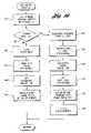
- FIGS. 8–12are flow diagrams illustrating programmable controller operation according to embodiments of the present invention.
- FIGS. 13–16are flow diagrams illustrating alternative programmable controller operation according to embodiments of the present invention.
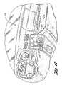
- FIG. 17is a drawing illustrating a vehicle interior that may be used to program a programmable controller according to an embodiment of the present invention
- FIG. 18is a block diagram illustrating a bus-based automotive vehicle electronics system according to an embodiment of the present invention.
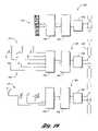
- FIG. 19is a block diagram illustrating distributed control elements interconnected by a vehicle bus according to an embodiment of the present invention.
- FIG. 1a block diagram illustrating an appliance control system according to an embodiment of the present invention is shown.
- An appliance control systemshown generally by 20 , allows one or more appliances to be remotely controlled using radio transmitters.
- radio frequency remote controlsare used to operate a garage door opener.
- the present inventionmay be applied to controlling a wide variety of appliances such as other mechanical barriers, lighting, alarm systems, temperature control systems, and the like.
- Appliance control system 20includes garage 22 having a garage door, not shown.
- Garage door opener (GDO) receiver 24receives radio frequency control signals 26 for controlling a garage door opener.
- Activation signalshave a transmission scheme which may be represented as a set of receiver characteristics.
- One or more existing transmitters (ET) 28generate radio frequency activation signals 26 exhibiting the receiver characteristics in response to a user depressing an activation button.
- a user of appliance control system 20may wish to add a new transmitter to system 20 .
- a vehicle-based transmitter (VBT) including programable control 30may be installed in vehicle 32 , which may be parked in garage 22 .
- Vehicle-based transmitter 30generates a sequence of activation signals 34 which includes an activation signal having characteristics appropriate to activate activating garage door opener receiver 24 .
- programmable control 30is mounted in vehicle 32 .
- the present inventionapplies to universal remote controls that may be mounted anywhere.
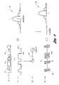
- FIG. 2a schematic diagram illustrating activation signal characteristics according to an embodiment of the present invention is shown.
- Information transmitted in an activation signalis typically represented as a binary data word, shown generally by 60 .
- Data word 60may include one or more fields, such as transmitter identifier 62 , function indicator 64 , code word 66 , and the like.
- Transmitter identifier (TRANS ID) 62uniquely identifies a remote control transmitter.
- Function indicator 64indicates which of a plurality of functional buttons on the remote control transmitter were activated.
- Code word 66helps to prevent misactivation and unauthorized access.
- codes 66are possible.
- One type of codeis a fixed code, wherein each transmission from a given remote control transmitter contains the same code 66 .
- variable code schemeschange the bit pattern of code 66 with each activation.
- the most common variable code schemeknown as rolling code, generates code 66 by encrypting a synchronization (sync) counter value. After each activation, the counter is incremented.
- the encryption techniqueis such that a sequence of encrypted counter values appears to be random numbers.
- Data word 60is converted to a baseband stream, shown generally by 70 , which is an analog signal typically transitioning between a high voltage level and a low voltage level. Multilevel transmissions are also possible. Various baseband encoding or modulation schemes are known, including polar signaling, on-off signaling, bipolar signaling, duobinary signaling, Manchester signaling, and the like.
- Baseband stream 70has a baseband power spectral density, shown generally by 72 , centered around a frequency of zero.
- Baseband stream 70is converted to a radio frequency signal through a modulation process shown generally by 80 .
- Baseband stream 70is used to modulate one or more characteristics of carrier 82 to produce a broadband signal, shown generally by 84 .
- Modulation process 80mathematically illustrated by multiplication in FIG. 2 , implements a form of amplitude modulation commonly referred to as on-off keying. As will be recognized by one of ordinary skill in the art, many other modulation forms are possible, including frequency modulation, phase modulation, and the like.
- baseband stream 70forms envelope 86 modulating carrier 82 .
- broadband power spectral density 88the effect in the frequency domain is to shift baseband power spectral density 72 up in frequency so as to be centered around the carrier frequency, f, of carrier 82 .
- FIG. 3a block diagram illustrating rolling code operation that may be used with the present invention is shown.
- Remotely controlled systems using rolling coderequire crypt key 100 in both the transmitter and the receiver for normal operation.
- crypt key 100is not transmitted from the transmitter to the receiver.
- crypt key 100is generated using key generation algorithm 102 based on transmitter identifier 62 and a manufacturing (MFG) key 104 .
- Crypt key 100 and transmitter identifier 62are then stored in a particular transmitter.
- Counter 106is also initialized in the transmitter.
- the transmitteruses encrypt algorithm 108 to generate rolling code value 110 from counter 106 using crypt key 100 .
- the transmitted activation signalincludes rolling code 110 and transmitter identifier 62 .
- a rolling code receiveris trained to a compatible transmitter prior to normal operation.
- the receiveris placed into a learn mode.
- the receiverextracts transmitter identifier 62 .
- the receiveruses key generation algorithm 102 with manufacturing key 104 and received transmitter identifier 62 to generate crypt key 100 identical to the crypt key used by the transmitter.
- Newly generated crypt key 100is used by decrypt algorithm 112 to decrypt rolling code 110 , producing counter 114 equal to counter 106 .
- the receiverthen saves counter 114 and crypt key 100 associated with transmitter identifier 62 .
- encrypt algorithm 108 and decrypt algorithm 112may be the same algorithm.
- the receiverwhen the receiver receives an activation signal, the receiver first extracts transmitter identifier 62 and compares transmitter identifier 62 with all learned transmitter identifiers. If no match is found, the receiver rejects the activation signal. If a match is found, the receiver retrieves crypt key 100 associated with received transmitter identifier 62 and decrypts rolling code 110 from the received activation signal to produce counter 114 . If received counter 106 matches counter 114 associated with transmitter identifier 62 , activation proceeds. Received counter 106 may also exceed stored counter 114 by a preset amount for successful activation.
- Another rolling code schemegenerates crypt key 100 based on manufacturing key 104 and a “seed” or random number.
- An existing transmittersends this seed to an appliance receiver when the receiver is placed in learn mode.
- the transmittertypically has a special mode for transmitting the seed that is entered, for example, by pushing a particular combination of buttons.
- the receiveruses the seed to generate crypt key 100 .
- the present inventionapplies to the use of a seed for generating a crypt key as well as to any other variable code scheme.
- fixed code receiver 24 and transmitter 28may each include printed circuit board 120 having a plurality of pins, one of which is indicated by 122 , together with support electronics, not shown.
- Pins 122are arranged in a grid having three rows and a number of columns equal to the number of bits in the fixed code value.
- a jumperone of which is indicated by 124 , is placed in each column straddling either the first and second pins or the second and third pins.
- One positionrepresents a logical “1” and the other position represents a logical “0.”
- Various alternative schemesare also possible. For example, two rows may be used, with the presence or absence of jumper 124 indicating one of the logical binary values.
- a set of DIP switchesmay be used with “up” representing one binary value and “down” representing the other.
- a useris asked to read the fixed code value from existing transmitter 28 or appliance receiver 24 and enter this fixed code value into programmable control 30 .
- a difficulty experienced by users asked to read such valuesis in determining from which end to start. Another difficulty is in determining which setting represents a binary “1” and which setting represents a binary “0. ”
- the pattern represented in FIG. 4may be interpreted as “00011010,” “11100101,” “01011000” or “10100111.” Entering an incorrect value can frustrate a user who is not sure why he cannot program his fixed code transmitter.
- embodiments of the present inventiontransmits fixed code activation signals based on the fixed code value as entered by the user and at least one of a bitwise reversal of the fixed code, a bitwise inversion of the fixed code, and both a bitwise reversal and inversion.
- Programmable control 30includes control logic 130 and a transmitter section, shown generally by 132 .
- Transmitter section 132includes variable frequency oscillator 134 , modulator 136 , variable gain amplifier 138 and antenna 140 .
- control logic 130sets the carrier frequency of the activation signal generated by variable frequency oscillator 134 using frequency control signal 142 .
- Control logic 132modulates the carrier frequency with modulator 136 , modeled here as a switch, to produce an activation signal which is amplified by variable gain amplifier 138 .
- Modulator 136may be controlled by shifting a data word serially onto modulation control signal 144 .
- Other forms of modulationare possible, such as frequency modulation, phase modulation, and the like.
- Variable gain amplifier 138is set to provide the maximum allowable output power to antenna 140 using gain control signal 146 .
- Control logic 130receives user input 148 providing fixed code programming information and activation inputs.
- User input 148may be implemented with one or more switches directly connected to control logic 130 .
- user input 148may be provided through remote input devices connected to control logic 130 via a serial bus.
- Control logic 130generates one or more user outputs 150 .
- User outputs 150may include indicator lamps directly connected to control logic 130 and/or remote display devices connected to control logic 130 through a serial bus.
- Control logic 130 and electronics for a user interfacecan be implemented with microcontroller 162 .
- User interface 160includes at least one activation input, shown generally by 164 . Three activation inputs 164 are shown, labeled “A,” “B” and “C.” Each activation input 164 is implemented with one pushbutton switch 166 . Each pushbutton switch 166 provides a voltage signal to a digital input (DI) for microcontroller 162 .
- User interface 160also includes one indicator lamp 168 associated with each activation input 164 . Each indicator lamp 168 may be implemented using one or more light emitting diodes supplied by a digital output (DO) from microcontroller 162 .
- DOdigital output
- User interface 160can include a plurality of DIP switches, one of which is indicated by 170 , for implementing programming input 172 .
- DIP switches 170are set to match the fixed code value from fixed code appliance receiver 24 or associated existing transmitter 28 .
- Microcontroller 162reads DIP switches 170 using parallel bus 174 .
- programming input 172may be implemented using pushbutton switches 166 as will be described in greater detail below.
- Microcontroller 162generates control signals determining characteristics of transmitted activation signals.
- Frequency control signal 142is delivered from an analog output (AO) on microcontroller 162 .
- AOanalog output
- Frequency control signal 142may also be one or more digital outputs used to select between fixed frequency sources.
- Modulation control signal 144is provided by a digital output on microcontroller 162 . The fixed or rolling code data word is put out on modulation control 144 in conformance with the baseband modulation and bit rate characteristics of the activation scheme being implemented.
- Microcontroller 162generates gain control signal 146 as an analog output for controlling the amplitude of the activation signal generated.
- analog output signalsmay be replaced by digital output signals feeding an external digital-to-analog converter.
- a memory mapfor implementing operating modes according to an embodiment of the present invention is shown.
- a memory mapshown generally by 190 , represents the allocation of memory for data tables used by programmable control 30 . Preferably, this data is held in non-volatile memory such as flash memory.
- Memory map 190includes channel table 192 , mode table 194 and scheme table 196 .
- Channel table 192includes a channel entry, one of which is indicated by 198 , for each channel supported by programmable control 30 .
- each channelcorresponds to a user activation input.
- three channelsare supported.
- Each channel entry 198has two fields, mode indicator 200 and fixed code 202 .
- Mode indicator 200indicates the mode programmed for that channel.
- a zero in mode indicator 200indicates rolling code mode.
- a non-zero integer in mode indicator 200indicates a fixed code mode with a code size equal to the integer value.
- Fixed code value 202holds the programmed fixed code for a fixed code mode.
- Fixed code value 202may also hold function code 64 in fixed code modes.
- Fixed code value 202may hold function code 64 or may not be used at all in a channel programmed for a rolling code mode.
- Mode table 194contains an entry for each mode supported.
- the four entries illustratedare rolling code entry 204 , eight-bit fixed code entry 206 , nine-bit fixed code entry 208 and ten-bit fixed code entry 210 .
- Each entrybegins with mode indicator 200 for the mode represented, the next value is scheme count 212 indicating the number of schemes to be sequentially transmitted in that mode. Following scheme count 212 is a scheme address 214 for each scheme.
- the address of the first entry of mode table 194is held in table start pointer 216 known by control logic 130 .
- control logic 130searches through mode table 194 for mode indicator 200 matching the desired mode.
- mode indicators 200 and scheme counts 212provides a flexible representation for adding new schemes to each mode and adding new modes to mode table 194 .
- Scheme table 196holds characteristics and other information necessary for generating each activation signal in sequence of activation signals 34 .
- Scheme table 196includes a plurality of rolling code entries, one of which is indicated by 220 , and a plurality of fixed code entries, one of which is indicated by 222 .
- Each rolling code entry 220includes transmitter identifier 62 , counter 106 , crypt key 100 , carrier frequency 224 , and subroutine address 226 .
- Subroutine address 226points to code executable by control logic 130 for generating an activation signal. Additional characteristics may be embedded within this code.
- Each fixed code entry 222includes carrier frequency 224 and subroutine address 226 .
- Next pointer 228points to the next open location after scheme table 196 . Any new schemes received by control logic 130 may be appended to scheme table 196 using next pointer 228 .
- Memory map 190 illustrated in FIG. 7implements a single rolling code mode and three fixed code modes based on the fixed code size. Other arrangement of modes are possible. For example, more than one rolling code modes may be used. Only one fixed code mode may be used. If more than one fixed code mode is used, characteristics other than fixed code size may be used to distinguish between fixed code modes. For example, fixed code schemes may be grouped by carrier frequency, modulation technique, baseband modulation, and the like.
- channel table 192can hold different values for channel entries 198 .
- each channel entry 198could include scheme address 214 of a successfully trained scheme as well as fixed code value 202 .
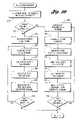
- FIGS. 8–16flow charts illustrating programmable control operation according to embodiments of the present invention are shown.
- the operations illustratedare not necessarily sequential operations.
- operationsmay be performed by software, hardware, or a combination of both.
- the present inventiontranscends any particular implementation and the aspects are shown in sequential flowchart form for ease of illustration.
- System initializationoccurs, as in block 240 .
- Control logic 130is preferably implemented with a microcontroller.
- Various ports and registersare typically initialized on power up.
- a checkis made to determine if this is a first power up occurrence, as in block 242 . If so, the mode for each channel is set to rolling code, as in block 244 .
- the systemthen waits for user input, as in block 246 . This waiting may be done either with power applied or removed.
- FIG. 9a flowchart illustrating response to user input is shown.
- the user inputis examined, as in block 250 .
- a checkis made for reset input, as in block 252 . If so, a reset routine is called, as in block 254 . If not, a check is made for activation input, as in block 256 . If so, an activation routine is called, as in block 258 . If not, a check is made to determine if fixed code training input has been received, as in block 260 . If so, a fixed code training routine is called, as in block 262 .
- Other input optionsare possible, such as placing programmable control 30 into a download mode for receiving data related to adding or changing activation schemes.
- programmable control 30Interpreting user input depends upon the type of user input supported by programmable control 30 .
- a button depression of short durationmay be used to signify activation input for the channel assigned to the button. Holding the button for a moderate length of time may be used to signify fixed training input. Holding the button for an extended period of time may be used to indicate reset input.
- different combinations of buttonsmay be used to place programmable control 30 into various modes of operation.
- the stored fixed codeis retrieved, as in block 274 .
- a data wordis formed using the fixed code, as in block 278 .
- the frequencyis set, as in block 280 .
- the data wordis modulated and transmitted, as in block 282 .
- a checkis made to determine if any schemes remain, as in block 284 . If so, blocks 276 , 278 , 280 and 282 are repeated. If not, the activation routine terminates.
- a rolling code activation signal loopis entered. Characteristics of the next rolling code scheme are loaded, as in block 286 . The synchronization counter associated with the current scheme is incremented, as in block 288 . The incremented counter value is also stored. The synchronization counter is encrypted using the crypt key to produce a rolling code value, as in block 290 . A data word is formed using the rolling code value, as in block 292 . The carrier frequency is set, as in block 294 . The data word is modulated and transmitted, as in block 296 . A check is made to determine if any schemes remain in the rolling code mode, as in block 298 . If so, blocks 286 , 288 , 290 , 292 , 294 and 296 are repeated. If no schemes remain, the activation routine is terminated.
- a flow chart illustrating fixed code trainingis shown.
- the useris prompted for input, as in block 300 .
- Promptingmay be accomplished, for example, by flashing one or more of indicator lamps 168 .
- other audio and/or visual promptsmay be provided to the user as will be described in greater detail below.
- User inputis received, as in block 302 .
- the userenters a fixed code value. This value may be entered in parallel such as, for example, through the use of DIP switches 170 .
- the usermay also enter fixed code information through one or more remote user inputs as will be described in greater detail below.
- Activation inputs 164provide another means for inputting a fixed code value. In a three button system, a first button can be used to input a binary “1,” a second button can be used to input a binary “0” and a third button can be used to indicate completion.
- Blocks 304 through 314describe serially inputting a fixed code value using activation inputs 164 .
- a checkis made to determine if an end of data input was received, as in block 304 . If not, a check is made to see if the input value was a binary “1,” as in block 306 . If so, a binary “1” is appended to the fixed code value, as in block 308 , and an indication of binary “1” is displayed, as in block 310 .
- This displaymay be, for example, illuminating indicator lamp 168 associated with activation input 164 used to input the binary “1.”
- a binary “0”is appended to the fixed code, as in block 312 .
- a display indicating a binary “0”is provided, as in block 314 .
- a loopis entered to generate a sequence of at least one fixed code activation signal.
- the next fixed code schemeis loaded, as in block 316 .
- this schemeis based on the number of bits in the received fixed code.
- a data wordis formed based on the loaded fixed scheme, as in block 318 .
- This data wordincludes the received fixed code either as received or as a binary modification of the received fixed code.
- the carrier frequencyis set based on the loaded scheme, as in block 320 .
- the carrieris modulated and the resulting activation signal transmitted, as in block 322 .
- a checkis made to determine if any schemes remain, as in block 324 .
- Each activation input channelis set to rolling mode, as in block 340 .
- the useris notified of successful reset, as in block 342 .
- a pattern of flashing indicator lampsmay be used for this indication.
- a reset routineis entered by asserting a particular user input 164 such as, for example, by depressing pushbutton switch 166 for an extended period of time, then only the mode corresponding to that user input need be reset by the reset routine.
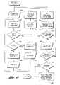
- FIGS. 13–16flowcharts illustrating alternative programmable controller operation according to embodiments of the present invention are shown.
- user input processing including rolling code trainingis provided.
- User inputis examined, as in block 350 .
- a determinationis made as to whether or not the input indicates a reset, as in block 352 . If so, a reset routine is called, as in block 354 .
- a determinationis made as to whether or not the input specified rolling code training, as in block 356 . If so, a rolling code training routine is called, as in block 358 . If not, a determination is made as to whether fixed code training input was received, as in block 360 . If so, a fixed code training routine is called, as in block 362 .
- Other inputsare possible such as, for example, input specifying a data download for adding or changing activation signal schemes or modes.
- the routineincludes a loop in which one or more rolling code activation signals are sent as a test.
- a userprovides feedback regarding whether or not the target appliance was activated.
- the next rolling code scheme in the sequenceis loaded, as in block 370 .
- the sync counterupon which the rolling code is based, is initialized, as in block 372 .
- the sync counteris encrypted according to the current scheme to generate a rolling code value, as in block 374 .
- a data wordis formed including the generated rolling code value, as in block 376 .
- the carrieris set, as in block 378 .
- the data wordis used to modulate the carrier according to the current scheme, as in block 380 .
- the resulting activation signalis then transmitted.
- the guess-and-test approachrequires interaction with the user.
- the testpauses until either a positive input or a negative input is received from the user, as in block 382 .
- the testpauses for a preset amount of time. If no user input is received within this time, the system assumes the current test has failed. A check for success is made, as in block 384 . If the user indicates activation, information indicating the one or more successful schemes is saved, as in block 386 . This information may be associated with a particular user activation input. The user may assign a particular user activation input as part of block 382 or may be prompted to designate an activation input as part of block 386 .
- the training routine illustrated in FIG. 14indicates a single activation signal is generated for each test. However, multiple activation signals may be generated and sent with each test. In one embodiment, further tests are conducted to narrow down which scheme or schemes successfully activated the appliance. In another embodiment, the programmable control stores information indicating the successful sequence so that the successful sequence is retransmitted each time the appropriate activation input is received.
- an alternative fixed code training routineis provided.
- the useris prompted to input a fixed code value, as in block 400 .
- User inputis received, as in block 402 .
- the fixed code valuemay be input serially or parallelly through one or more of a variety of inputs including specially designated programming switches, activation inputs, remote input devices, and the like. If the fixed code value is serially entered by the user, a check is made to determine end of data, as in block 404 . If input did not indicate end of data, a check is made to determine if a binary “1” was input, as in block 406 .
- a binary “1”is appended to the fixed code, as in block 408 , and a binary “1” is displayed to the user, as in block 410 . If not, a binary “0” is appended to the fixed code, as in block 412 , and a binary “0” is displayed to the user, as in block 414 .
- a guess-and-test loopis entered.
- a displaymay be provided to the user indicating that the test is in progress, as in block 416 .
- Information describing the next fixed code schemeis loaded, as in block 418 .
- a data wordis formed containing the fixed code, as in block 420 .
- the carrier frequencyis set, as in block 422 .
- the data wordis used to modulate the carrier, producing an activation signal, which is then transmitted, as in block 424 .
- User input regarding the success of the testis received, as in block 426 .
- the systemmay pause for a preset amount of time and, if no input is received, assume that the test was not successful.
- the systemmay wait for user input specifically indicating success or failure.
- a checkis made to determine whether or not the test was successful, as in block 428 . If so, information specifying the one or more successful schemes and the fixed code value are saved. This information may be associated with a particular activation input specified by the user. In addition, the mode is changed to fixed mode for the selected activation input. If success was not indicated, a check is made to determine if any schemes remain, as in block 432 . If not, failure is indicated to the user, as in block 434 . If any schemes remain, the test loop is repeated.
- the guess-and-test scheme illustrated in FIG. 15generates and transmits a single activation signal with each pass through the loop. However, as with rolling code training, more than one fixed code activation signal may be sent within each test. Once success is indicated, the user may be prompted to further narrow the selection of successful activation signals. Alternatively, information describing the sequence can be stored and the entire sequence retransmitted upon receiving an activation signal to which the sequence is associated.
- FIG. 16a flow chart illustrating an activation routine according to an embodiment of the present invention is shown.
- Information associated with an asserted activation inputis retrieved, as in block 440 .
- a checkis made to determine if the mode associated with the activation channel is rolling, as in block 442 . If so, the sync counter is loaded and incremented, as in block 444 .
- the sync counteris encrypted to produce a rolling code value, as in block 446 .
- a data wordis formed including the rolling code value, as in block 448 .
- the carrier frequencyis set, as in block 450 .
- the data wordis used to modulate the carrier frequency, producing an activation signal which is then transmitted, as in block 452 .
- the sync counteris stored, as in block 454 .
- the stored fixed code valueis retrieved, as in block 456 .
- a data wordis formed including the retrieved fixed code, as in block 458 .
- the carrier frequencyis set, as in block 460 .
- the data wordis used to modulate the carrier, producing an activation signal which is then transmitted, as in block 462 .
- programmable control 30may implement a system which transmits every rolling code activation signal upon activation of a rolling code channel and uses guess-and-test training for programming a fixed code channel.
- programmable control 30may be configured for guess-and-test training using every possible rolling code scheme but, when training for fixed code, generates and transmits activation signals based on only those fixed code schemes known to be used with a fixed code value having a number of bits equal to the number of bits of the fixed code value entered by the user.
- a vehicle interiorshown generally by 470 , includes console 472 having one or more of a variety of user interface components.
- Graphical display 474 and associated display controls 476provide an interactive device for HVAC control, radio control, lighting control, vehicle status and information display, map and positioning display, routing and path planning information, and the like.
- Display 474can provide instructions for programming and using programmable control 30 .
- Display 474can also provide status and control feedback to the user in training and operating modes.
- Display controls 476including, if available, touch-screen input provided by display 474 can be used to provide programming input.
- display 474 and controls 476may be used as activation inputs for programmable control 30 .
- Console 472includes numeric keypad 478 associated with an in-vehicle telephone.
- numeric keypad 478can be used to enter the fixed code value.
- Programmable control 30may also recognize one or a sequence of key depressions on keypad 478 as an activation input.
- Console 472may include speaker 480 and microphone 482 associated with an in-vehicle telephone, voice activated control system, entertainment system, audible warning system, and the like.
- Microphone 482may be used to provide activation and/or programming inputs.
- Speaker 480can provide audio feedback during programming and/or activation modes.
- microphone 482 and speaker 480may be used to provide programming instructions, interactive help, and the like.
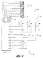
- An electronic systemshown generally by 490 , includes interconnecting bus 492 .
- Automotive communication busesmay be used to interconnect a wide variety of components within the vehicle, some of which may function as interface devices for programming or activating appliance controls.
- Many standards exist for specifying bus operationssuch as, for example, SAE J-1850, Controller Area Network (CAN), and the like.
- CANController Area Network
- Various manufacturersprovide bus interfaces 224 that handle low level signaling, handshaking, protocol implementation and other bus communication operations.
- Electronics system 490includes programmable control 30 .
- Programmable control 30includes at least control logic 130 and transmitter (TRANS) 132 .
- Control logic 130accesses memory 496 , which holds a plurality of activation schemes. Each scheme describes activation control signals used by control logic 130 to transmit activation signals by transmitter 132 .
- User interface 160interfaces control logic 130 with user activation inputs and outputs, not shown. User interface 160 may be directly connected to control logic 130 or may be connected through bus 492 . This latter option allows control logic 130 and transmitter 132 to be located anywhere within vehicle 32 .
- Electronics system 490may include wireless telephone 498 interfaced to bus 492 .
- Telephone 498can receive input from keypad 478 and from microphone 482 through microphone input 500 .
- Telephone 498provides audio output to speaker 480 through speaker driver 502 .
- Telephone 498may be used to contact a human or automated help system and may also be used as a data port to download scheme and software updates into memory 496 .
- Keypad 478may be directly interfaced to bus 492 allowing keypad 478 to provide user input to control logic 130 .
- Microphone 482provides voice input through microphone input 500 to speech recognizer 504 .
- Speech recognizer 504is interfaced to bus 492 allowing microphone 482 to provide input for control logic 130 .
- Sound generator 506supplies signals for audible reproduction to speaker 480 through speaker driver 502 .
- Sound generator 506may be capable of supplying tone-based signals and/or artificial speech signals. Sound generator 506 is interfaced to bus 492 allowing control logic 130 to send audible signals to a user
- Display controller 508generates signals controlling display 474 and accepts display control input 476 .
- Display controller 508is interfaced to bus 492 allowing control logic 130 to initiate graphical output on display 474 and receive user input from controls 476 .
- Radio 510is interfaced to bus 492 allowing control logic 130 to initiate display through radio 510 and receive input from controls on radio 510 .
- volume and tuning controls on radio 510may be used to enter a fixed code value. Rotating the volume knob may sequentially cycle through the most significant bits of the code and rotating the tuning knob may sequentially cycle through the least significant bits of the code. Pushing a radio control can then send the fixed code to control logic 130 .
- Wireless transceiver 512is interfaced to bus 492 through bus interface 494 .
- Wireless transceiver 512communicates with wireless communication devices, represented by 514 and 516 , such as portable telephones, personal digital assistants, laptop computers, and the like, through infrared or short range radio frequency signals.
- wireless communication devicesrepresented by 514 and 516
- wireless communication devicessuch as portable telephones, personal digital assistants, laptop computers, and the like
- Transceiver 512is interfaced to bus 492 , permitting wireless devices 514 , 516 to provide input to and receive output from control logic 130 .
- Wireless devices 514 , 516may also be used as a data port to upload code and scheme data into memory 496 and/or to exchange data with programmable control 30 for assisting in programming control 30 .
- Data port 518implements a data connection interfaced to bus 492 through bus interface 494 .
- Data port 518provides a plug or other interface for exchanging digital information.
- One or more standardsmay be supported, such as IEEE 1394, RS-232, SCSI, USB, PCMCIA, and the like.
- Proprietary information exchange or vehicle diagnostic portsmay also be supported.
- Data port 518may be used to upload code and scheme data into memory 496 and/or exchange data with programmable control 30 for assisting in programming control 30 .
- Bus 492is a CAN bus.
- Bus interface 494may be implemented with CAN transceiver 530 and CAN controller 532 .
- CAN transceiver 530may be a PCA82C250 transceiver from Philips Semiconductors.
- CAN controller 232may be a SJA 1000 controller from Philips Semiconductors.
- CAN controller 232is designed to connect directly with data, address and control pins of certain microcontrollers such as, for example, an 80C51 family microcontroller from Intel Corporation.
- control logic 130 and transmitter 132are supported by a first bus interface 494 .
- Activation inputs 164provide inputs to, and indicators 168 are driven by, microcontroller 534 which is supported by a second bus interface 494 .
- Programming input switches 172are connected in parallel to microcontroller 536 which is supported by a third bus interface 494 .
- Serial bus 492 and separate interfaces 494permit various components of programmable control 30 to be placed in different locations within vehicle 32 .
- One advantage of separate locationis that transmitter 132 need not be placed near user controls 164 , 168 , 172 . Instead, transmitter 132 may be placed at a location optimizing radio frequency transmission from vehicle 32 .
- activation inputs 164 and indicator lamps 168may be located for easy user access such as in an overhead console, a visor, a headliner, and the like.
- Programming input controls 172which would be infrequently used, may be placed in a more hidden location such as inside of a glove box, trunk, storage compartment, and the like.
- Yet another advantage of a bus-based programmable control 30is the ability to interface control logic 130 with a wide variety of vehicle controls and displays.
Landscapes
- Physics & Mathematics (AREA)
- General Physics & Mathematics (AREA)
- Engineering & Computer Science (AREA)
- Computer Networks & Wireless Communication (AREA)
- Selective Calling Equipment (AREA)
Abstract
Description
Claims (26)
Priority Applications (4)
| Application Number | Priority Date | Filing Date | Title |
|---|---|---|---|
| US10/630,173US7183941B2 (en) | 2003-07-30 | 2003-07-30 | Bus-based appliance remote control |
| DE102004036511ADE102004036511A1 (en) | 2003-07-30 | 2004-07-28 | Bus-based device remote control |
| GB0416789AGB2404478B (en) | 2003-07-30 | 2004-07-28 | Bus-based appliance remote control |
| US11/522,631US7760071B2 (en) | 2003-07-30 | 2006-09-18 | Appliance remote control having separated user control and transmitter modules remotely located from and directly connected to one another |
Applications Claiming Priority (1)
| Application Number | Priority Date | Filing Date | Title |
|---|---|---|---|
| US10/630,173US7183941B2 (en) | 2003-07-30 | 2003-07-30 | Bus-based appliance remote control |
Related Child Applications (1)
| Application Number | Title | Priority Date | Filing Date |
|---|---|---|---|
| US11/522,631Continuation-In-PartUS7760071B2 (en) | 2003-07-30 | 2006-09-18 | Appliance remote control having separated user control and transmitter modules remotely located from and directly connected to one another |
Publications (2)
| Publication Number | Publication Date |
|---|---|
| US20050024255A1 US20050024255A1 (en) | 2005-02-03 |
| US7183941B2true US7183941B2 (en) | 2007-02-27 |
Family
ID=32962808
Family Applications (2)
| Application Number | Title | Priority Date | Filing Date |
|---|---|---|---|
| US10/630,173Expired - Fee RelatedUS7183941B2 (en) | 2003-07-30 | 2003-07-30 | Bus-based appliance remote control |
| US11/522,631Expired - Fee RelatedUS7760071B2 (en) | 2003-07-30 | 2006-09-18 | Appliance remote control having separated user control and transmitter modules remotely located from and directly connected to one another |
Family Applications After (1)
| Application Number | Title | Priority Date | Filing Date |
|---|---|---|---|
| US11/522,631Expired - Fee RelatedUS7760071B2 (en) | 2003-07-30 | 2006-09-18 | Appliance remote control having separated user control and transmitter modules remotely located from and directly connected to one another |
Country Status (3)
| Country | Link |
|---|---|
| US (2) | US7183941B2 (en) |
| DE (1) | DE102004036511A1 (en) |
| GB (1) | GB2404478B (en) |
Cited By (12)
| Publication number | Priority date | Publication date | Assignee | Title |
|---|---|---|---|---|
| US20060202796A1 (en)* | 2005-02-23 | 2006-09-14 | Sommer Antriebs- Und Funktechnik Gmbh | Closing system |
| US20060238297A1 (en)* | 2005-04-26 | 2006-10-26 | Lear Corporation | System and method for integrated garage door opener and vehicle entry using multi-frequency transmitter |
| US20070178891A1 (en)* | 2006-01-30 | 2007-08-02 | Louch John O | Remote control of electronic devices |
| US20080161047A1 (en)* | 1999-05-26 | 2008-07-03 | Johnson Controls Technology Company | System and method for radio frequency communication with a personal digital assistant in a vehicle |
| US20090082928A1 (en)* | 1999-05-26 | 2009-03-26 | Johnson Controls Technology Company | Wireless communications system and method |
| US20090268922A1 (en)* | 2005-08-31 | 2009-10-29 | Mitsubishi Materials Corporation | Personal computer adaptor device, personal computer signal reproducing system, personal computer reproducing method, personal computer signal reproducing program, output device control program, personal computer adaptor device control program, personal computer control program, power line communication connector device, cradle device using the same, and power line communication reproducing system |
| US7769346B1 (en)* | 2003-10-31 | 2010-08-03 | Johnson Controls Technology Company | Wireless electrical connectivity system for use in a vehicle |
| US20150302733A1 (en)* | 2014-04-18 | 2015-10-22 | Gentex Corporation | Trainable transceiver and mobile communications device diagnostic systems and methods |
| US9652907B2 (en) | 2014-05-08 | 2017-05-16 | Gentex Corporation | Fixed location based trainable transceiver for the control of remote devices systems and methods |
| US9947159B2 (en) | 2014-02-11 | 2018-04-17 | Gentex Corporation | Systems and methods for adding a trainable transceiver to a vehicle |
| US10963825B2 (en) | 2013-09-23 | 2021-03-30 | Farmobile, Llc | Farming data collection and exchange system |
| USD975038S1 (en) | 2021-05-19 | 2023-01-10 | Gmi Holdings, Inc. | Wireless wall console |
Families Citing this family (36)
| Publication number | Priority date | Publication date | Assignee | Title |
|---|---|---|---|---|
| US7167076B2 (en)* | 2001-12-19 | 2007-01-23 | Lear Corporation | Universal garage door operating system and method |
| US20030197595A1 (en)* | 2002-04-22 | 2003-10-23 | Johnson Controls Technology Company | System and method for wireless control of multiple remote electronic systems |
| WO2004077729A2 (en) | 2003-02-21 | 2004-09-10 | Johnson Controls Technology Company | Trainable remote controller and method for determining the frequency of a learned control signal |
| US8174357B2 (en)* | 2002-11-08 | 2012-05-08 | Johnson Controls Technology Company | System and method for training a transmitter to control a remote control system |
| WO2004043750A2 (en) | 2002-11-08 | 2004-05-27 | Johnson Controls Technology Company | Trainable transceiver system |
| US7116242B2 (en)* | 2002-11-27 | 2006-10-03 | Lear Corporation | Programmable transmitter and receiver including digital radio frequency memory |
| US7183941B2 (en) | 2003-07-30 | 2007-02-27 | Lear Corporation | Bus-based appliance remote control |
| US7039397B2 (en) | 2003-07-30 | 2006-05-02 | Lear Corporation | User-assisted programmable appliance control |
| US7183940B2 (en)* | 2003-07-30 | 2007-02-27 | Lear Corporation | Radio relay appliance activation |
| US7269416B2 (en)* | 2003-07-30 | 2007-09-11 | Lear Corporation | Universal vehicle based garage door opener control system and method |
| US7088218B2 (en)* | 2003-07-30 | 2006-08-08 | Lear Corporation | Wireless appliance activation transceiver |
| US7120430B2 (en)* | 2003-07-30 | 2006-10-10 | Lear Corporation | Programmable interoperable appliance remote control |
| US7161466B2 (en)* | 2003-07-30 | 2007-01-09 | Lear Corporation | Remote control automatic appliance activation |
| US7068181B2 (en)* | 2003-07-30 | 2006-06-27 | Lear Corporation | Programmable appliance remote control |
| US7084781B2 (en)* | 2003-07-30 | 2006-08-01 | Lear Corporation | Programmable vehicle-based appliance remote control |
| DE102005011487A1 (en)* | 2005-03-12 | 2006-09-14 | Bayerische Motoren Werke Ag | Procedure for authorizing external devices |
| FR2890222A1 (en)* | 2005-08-29 | 2007-03-02 | Andre Poulat | Security system and electric appliance remote activation and control system for e.g. door motor control, has remote control controlling appliances, and actuator modules with registers processing security codes and manufacturer codes |
| JP4539513B2 (en)* | 2005-09-26 | 2010-09-08 | トヨタ自動車株式会社 | Remote control device for vehicle |
| US8384513B2 (en)* | 2006-01-03 | 2013-02-26 | Johnson Controls Technology Company | Transmitter and method for transmitting an RF control signal |
| US7589613B2 (en)* | 2006-04-03 | 2009-09-15 | Lear Corporation | Trinary to trinary rolling code generation method and system |
| WO2008082482A2 (en)* | 2006-12-21 | 2008-07-10 | Johnson Controls Technology Company | System and method for extending transmitter training window |
| US20080169899A1 (en)* | 2007-01-12 | 2008-07-17 | Lear Corporation | Voice programmable and voice activated vehicle-based appliance remote control |
| WO2008110610A1 (en)* | 2007-03-15 | 2008-09-18 | Takata-Petri Ag | Motor vehicle seat arrangement and method for protecting a vehicle passenger |
| US8362886B2 (en)* | 2007-09-26 | 2013-01-29 | Omega Patents, L.L.C. | Multi-controller data bus adaptor and associated methods |
| EP2310234B1 (en)* | 2008-07-15 | 2014-09-03 | Takata AG | Vehicle seat arrangement and airbag arrangement for motor vehicle and method for protecting a vehicle occupant |
| CL2009001884A1 (en)* | 2008-10-02 | 2010-05-14 | Incyte Holdings Corp | Use of 3-cyclopentyl-3- [4- (7h-pyrrolo [2,3-d] pyrimidin-4-yl) -1h-pyrazol-1-yl) propanonitrile, janus kinase inhibitor, and use of a composition that understands it for the treatment of dry eye. |
| CA2800127C (en) | 2010-06-09 | 2021-04-13 | Conocophillips Company | Seismic data acquisition using designed non-uniform receiver spacing |
| US8970352B2 (en)* | 2012-10-23 | 2015-03-03 | GM Global Technology Operations LLC | Remote activated garage door opener functions via a graphical user interface in a vehicle |
| KR102051370B1 (en)* | 2013-04-09 | 2019-12-03 | 엘지전자 주식회사 | A laundry and a controlling method of a laundry |
| AU2015364405A1 (en) | 2014-12-18 | 2017-08-03 | Joel Brewer | Methods for simultaneous source separation |
| AU2016332565B2 (en) | 2015-09-28 | 2022-07-21 | Shearwater Geoservices Software Inc. | 3D seismic acquisition |
| CA2972313A1 (en)* | 2016-07-06 | 2018-01-06 | Frank Barassi | Remote starter system with flashable antenna |
| JP6568668B1 (en)* | 2016-07-14 | 2019-08-28 | シグニファイ ホールディング ビー ヴィ | Lighting control |
| US10809402B2 (en) | 2017-05-16 | 2020-10-20 | Conocophillips Company | Non-uniform optimal survey design principles |
| WO2019100068A1 (en) | 2017-11-20 | 2019-05-23 | Conocophillips Company | Offshore application of non-uniform optimal sampling survey design |
| US11481677B2 (en) | 2018-09-30 | 2022-10-25 | Shearwater Geoservices Software Inc. | Machine learning based signal recovery |
Citations (217)
| Publication number | Priority date | Publication date | Assignee | Title |
|---|---|---|---|---|
| US1522241A (en) | 1923-07-25 | 1925-01-06 | Phinney Walker Company | Mirror clock |
| US3098212A (en) | 1959-05-11 | 1963-07-16 | Philco Corp | Remote control system with pulse duration responsive means |
| US3300867A (en) | 1964-03-23 | 1967-01-31 | Kaman Aircraft Corp | Magnetic compass |
| US3337992A (en) | 1965-12-03 | 1967-08-29 | Clyde A Tolson | Remotely controlled closures |
| US3456387A (en) | 1967-07-06 | 1969-07-22 | Clyde A Tolson | Remotely controlled closures |
| US3680951A (en) | 1970-04-01 | 1972-08-01 | Baldwin Co D H | Photoelectrically-controlled rear-view mirrow |
| US4074200A (en) | 1975-12-10 | 1978-02-14 | Siemens Aktiengesellschaft | Circuit arrangement for selective frequency analysis of the amplitudes of one or more signals |
| US4167833A (en) | 1977-07-26 | 1979-09-18 | Metro-Dynamics, Inc. | Overhead garage door opener |
| US4178549A (en) | 1978-03-27 | 1979-12-11 | National Semiconductor Corporation | Recognition of a received signal as being from a particular transmitter |
| US4219812A (en) | 1978-12-26 | 1980-08-26 | The United States Of America As Represented By The Secretary Of The Army | Range-gated pulse doppler radar system |
| US4241870A (en) | 1978-10-23 | 1980-12-30 | Prince Corporation | Remote transmitter and housing |
| US4247850A (en) | 1977-08-05 | 1981-01-27 | Prince Corporation | Visor and garage door operator assembly |
| US4425717A (en) | 1982-06-24 | 1984-01-17 | Prince Corporation | Vehicle magnetic sensor |
| US4447808A (en) | 1981-09-18 | 1984-05-08 | Prince Corporation | Rearview mirror transmitter assembly |
| US4453161A (en) | 1980-02-15 | 1984-06-05 | Lemelson Jerome H | Switch activating system and method |
| US4482947A (en) | 1982-04-12 | 1984-11-13 | Zenith Electronics Corporation | Multi-function, multi-unit remote control system and method therefor |
| US4529980A (en) | 1982-09-23 | 1985-07-16 | Chamberlain Manufacturing Corporation | Transmitter and receiver for controlling the coding in a transmitter and receiver |
| US4535333A (en) | 1982-09-23 | 1985-08-13 | Chamberlain Manufacturing Corporation | Transmitter and receiver for controlling remote elements |
| US4581827A (en) | 1984-09-25 | 1986-04-15 | Niles Parts Co., Ltd. | Car door mirror equipped with bearing magnetometer |
| US4595228A (en) | 1984-04-30 | 1986-06-17 | Prince Corporation | Garage door opening transmitter compartment |
| US4598287A (en) | 1982-05-25 | 1986-07-01 | Sony Corporation | Remote control apparatus |
| GB2171545A (en) | 1985-02-21 | 1986-08-28 | Jing Tarng Lin | Radio remote control apparatus with encoded signals for automatic rolling doors |
| US4623887A (en) | 1984-05-15 | 1986-11-18 | General Electric Company | Reconfigurable remote control |
| US4631708A (en) | 1981-12-18 | 1986-12-23 | Senelco Limited | Transmitter/responder systems |
| US4635033A (en) | 1984-03-28 | 1987-01-06 | Nippondenso Co., Ltd. | Display system for automotive vehicle |
| US4638433A (en) | 1984-05-30 | 1987-01-20 | Chamberlain Manufacturing Corporation | Microprocessor controlled garage door operator |
| US4665397A (en) | 1983-11-01 | 1987-05-12 | Universal Photonics, Inc. | Apparatus and method for a universal electronic locking system |
| GB2182790A (en) | 1985-10-09 | 1987-05-20 | Hal Laboratory Inc | Infrared remote control system |
| US4676601A (en) | 1983-11-14 | 1987-06-30 | Nippondenso Co., Ltd. | Drive apparatus for a liquid crystal dazzle-free mirror arrangement |
| US4700327A (en) | 1984-12-31 | 1987-10-13 | Raytheon Company | Digital memory system |
| US4703359A (en) | 1985-05-30 | 1987-10-27 | Nap Consumer Electronics Corp. | Universal remote control unit with model identification capability |
| US4706299A (en) | 1984-05-15 | 1987-11-10 | Jorgensen Peter O | Frequency encoded logic devices |
| US4707788A (en) | 1984-07-10 | 1987-11-17 | Nippon Soken, Inc | Automatic adjuster for automobile driver equipment |
| USRE32576E (en) | 1984-01-18 | 1988-01-12 | Combination rear view mirror and digital clock | |
| US4727302A (en) | 1985-03-23 | 1988-02-23 | Alps Electric Co., Ltd. | Rear view mirror position control device of automobile |
| US4743905A (en) | 1985-08-16 | 1988-05-10 | Westinghouse Electric Corp. | Electronic counter measure system utilizing a digital RF memory |
| US4747159A (en) | 1985-07-24 | 1988-05-24 | Alps Electric Co., Ltd. | RF modulator |
| US4750118A (en) | 1985-10-29 | 1988-06-07 | Chamberlain Manufacturing Corporation | Coding system for multiple transmitters and a single receiver for a garage door opener |
| US4754255A (en) | 1984-03-12 | 1988-06-28 | Sanders Rudy T | User identifying vehicle control and security device |
| US4771283A (en) | 1985-01-16 | 1988-09-13 | Alpine Electronics Inc. | Remote control device |
| US4793690A (en) | 1986-07-18 | 1988-12-27 | Donnelly Corporation | Rearview mirror control circuit |
| US4799189A (en) | 1985-07-26 | 1989-01-17 | Motorola, Inc. | Resynthesized digital radio frequency memory |
| US4806930A (en) | 1986-08-01 | 1989-02-21 | Chamberlain Manufacturing Corporation | Radio control transmitter which suppresses harmonic radiation |
| US4825200A (en) | 1987-06-25 | 1989-04-25 | Tandy Corporation | Reconfigurable remote control transmitter |
| US4881148A (en) | 1987-05-21 | 1989-11-14 | Wickes Manufacturing Company | Remote control system for door locks |
| US4882565A (en) | 1988-03-02 | 1989-11-21 | Donnelly Corporation | Information display for rearview mirrors |
| US4886960A (en) | 1987-04-08 | 1989-12-12 | Donnelly Mirrors Limited | Control circuit for an automatic rearview mirror |
| US4890108A (en) | 1988-09-09 | 1989-12-26 | Clifford Electronics, Inc. | Multi-channel remote control transmitter |
| US4896030A (en) | 1987-02-27 | 1990-01-23 | Ichikoh Industries Limited | Light-reflectivity controller for use with automotive rearview mirror using electrochromic element |
| US4905279A (en) | 1988-02-26 | 1990-02-27 | Nec Home Electronics Ltd. | Learning-functionalized remote control receiver |
| US4912463A (en) | 1988-08-09 | 1990-03-27 | Princeton Technology Corporation | Remote control apparatus |
| US4917477A (en) | 1987-04-06 | 1990-04-17 | Gentex Corporation | Automatic rearview mirror system for automotive vehicles |
| US4953305A (en) | 1987-05-27 | 1990-09-04 | Prince Corporation | Vehicle compass with automatic continuous calibration |
| US4978944A (en) | 1987-10-20 | 1990-12-18 | Telefind Corporation | Paging receiver with dynamically programmable channel frequencies |
| US4988992A (en) | 1989-07-27 | 1991-01-29 | The Chamberlain Group, Inc. | System for establishing a code and controlling operation of equipment |
| US5016996A (en) | 1989-11-03 | 1991-05-21 | Yasushi Ueno | Rearview mirror with operating condition display |
| US5064274A (en) | 1987-08-26 | 1991-11-12 | Siegel-Robert, Inc. | Automatic automobile rear view mirror assembly |
| US5085062A (en) | 1988-09-28 | 1992-02-04 | Juan Capdevila | Keys and related magnetic locks to control accesses |
| US5103221A (en) | 1988-12-06 | 1992-04-07 | Delta Elettronica S.P.A. | Remote-control security system and method of operating the same |
| US5109222A (en) | 1989-03-27 | 1992-04-28 | John Welty | Remote control system for control of electrically operable equipment in people occupiable structures |
| US5113821A (en) | 1990-05-15 | 1992-05-19 | Mitsubishi Denki Kabushiki Kaisha | Vehicle speed governor |
| US5122647A (en) | 1990-08-10 | 1992-06-16 | Donnelly Corporation | Vehicular mirror system with remotely actuated continuously variable reflectance mirrors |
| US5123008A (en) | 1988-03-16 | 1992-06-16 | Shaye Communications Limited | Single frequency time division duplex transceiver |
| US5126686A (en) | 1989-08-15 | 1992-06-30 | Astec International, Ltd. | RF amplifier system having multiple selectable power output levels |
| US5146215A (en) | 1987-09-08 | 1992-09-08 | Clifford Electronics, Inc. | Electronically programmable remote control for vehicle security system |
| US5154617A (en) | 1989-05-09 | 1992-10-13 | Prince Corporation | Modular vehicle electronic system |
| US5181423A (en) | 1990-10-18 | 1993-01-26 | Hottinger Baldwin Messtechnik Gmbh | Apparatus for sensing and transmitting in a wireless manner a value to be measured |
| US5191610A (en) | 1992-02-28 | 1993-03-02 | United Technologies Automotive, Inc. | Remote operating system having secure communication of encoded messages and automatic re-synchronization |
| US5193210A (en) | 1991-07-29 | 1993-03-09 | Abc Auto Alarms, Inc. | Low power RF receiver |
| US5201067A (en) | 1991-04-30 | 1993-04-06 | Motorola, Inc. | Personal communications device having remote control capability |
| US5225847A (en) | 1989-01-18 | 1993-07-06 | Antenna Research Associates, Inc. | Automatic antenna tuning system |
| US5243322A (en) | 1991-10-18 | 1993-09-07 | Thompson Stephen S | Automobile security system |
| US5252960A (en) | 1991-08-26 | 1993-10-12 | Stanley Home Automation | Secure keyless entry system for automatic garage door operator |
| US5252977A (en) | 1990-10-31 | 1993-10-12 | Tektronix, Inc. | Digital pulse generator using digital slivers and analog vernier increments |
| US5266945A (en) | 1985-11-27 | 1993-11-30 | Seiko Corp. | Paging system with energy efficient station location |
| US5278547A (en) | 1990-01-19 | 1994-01-11 | Prince Corporation | Vehicle systems control with vehicle options programming |
| WO1994002920A1 (en) | 1992-07-24 | 1994-02-03 | Siel Elettronica S.P.A. | Remote controller using electromagnetic waves with automatic learning functions |
| US5369706A (en) | 1993-11-05 | 1994-11-29 | United Technologies Automotive, Inc. | Resynchronizing transmitters to receivers for secure vehicle entry using cryptography or rolling code |
| US5379453A (en) | 1992-09-24 | 1995-01-03 | Colorado Meadowlark Corporation | Remote control system |
| US5402105A (en) | 1992-06-08 | 1995-03-28 | Mapa Corporation | Garage door position indicating system |
| US5408698A (en) | 1991-03-26 | 1995-04-18 | Kabushiki Kaisha Toshiba | Radio tele-communication device having function of variably controlling received signal level |
| US5412379A (en) | 1988-05-27 | 1995-05-02 | Lectron Products, Inc. | Rolling code for a keyless entry system |
| US5420925A (en) | 1994-03-03 | 1995-05-30 | Lectron Products, Inc. | Rolling code encryption process for remote keyless entry system |
| US5442340A (en) | 1988-12-05 | 1995-08-15 | Prince Corporation | Trainable RF transmitter including attenuation control |
| US5455716A (en) | 1990-08-14 | 1995-10-03 | Prince Corporation | Vehicle mirror with electrical accessories |
| US5463374A (en) | 1994-03-10 | 1995-10-31 | Delco Electronics Corporation | Method and apparatus for tire pressure monitoring and for shared keyless entry control |
| US5471668A (en) | 1994-06-15 | 1995-11-28 | Texas Instruments Incorporated | Combined transmitter/receiver integrated circuit with learn mode |
| US5473317A (en) | 1990-07-17 | 1995-12-05 | Kabushiki Kaisha Toshiba | Audio-visual system having integrated components for simpler operation |
| US5475366A (en) | 1988-12-05 | 1995-12-12 | Prince Corporation | Electrical control system for vehicle options |
| US5479155A (en) | 1988-12-05 | 1995-12-26 | Prince Corporation | Vehicle accessory trainable transmitter |
| US5517187A (en) | 1990-05-29 | 1996-05-14 | Nanoteq (Pty) Limited | Microchips and remote control devices comprising same |
| US5528230A (en) | 1992-01-06 | 1996-06-18 | Samsung Electronics Co., Ltd. | Remote control transmitter/receiver system |
| US5554977A (en) | 1993-01-07 | 1996-09-10 | Ford Motor Company | Remote controlled security system |
| US5564101A (en) | 1993-07-09 | 1996-10-08 | Universal Devices | Method and apparatus for transmitter for universal garage door opener |
| USRE35364E (en) | 1985-10-29 | 1996-10-29 | The Chamberlain Group, Inc. | Coding system for multiple transmitters and a single receiver for a garage door opener |
| US5594429A (en) | 1993-10-27 | 1997-01-14 | Alps Electric Co., Ltd. | Transmission and reception system and signal generation method for same |
| US5596316A (en) | 1995-03-29 | 1997-01-21 | Prince Corporation | Passive visor antenna |
| US5598475A (en) | 1995-03-23 | 1997-01-28 | Texas Instruments Incorporated | Rolling code identification scheme for remote control applications |
| GB2302751A (en) | 1995-06-27 | 1997-01-29 | Prince Corp | Trainable transceiver capable of learning variable codes |
| US5613732A (en) | 1994-09-22 | 1997-03-25 | Hoover Universal, Inc. | Vehicle seat armrest incorporating a transmitter unit for a garage door opening system |
| US5614885A (en) | 1988-12-05 | 1997-03-25 | Prince Corporation | Electrical control system for vehicle options |
| US5619190A (en) | 1994-03-11 | 1997-04-08 | Prince Corporation | Trainable transmitter with interrupt signal generator |
| US5645308A (en) | 1995-08-29 | 1997-07-08 | Prince Corporation | Sliding visor |
| US5661651A (en) | 1995-03-31 | 1997-08-26 | Prince Corporation | Wireless vehicle parameter monitoring system |
| US5680134A (en) | 1994-07-05 | 1997-10-21 | Tsui; Philip Y. W. | Remote transmitter-receiver controller system |
| US5680131A (en) | 1993-10-29 | 1997-10-21 | National Semiconductor Corporation | Security system having randomized synchronization code after power up |
| US5686904A (en) | 1991-05-29 | 1997-11-11 | Microchip Technology Incorporated | Secure self learning system |
| US5686903A (en) | 1995-05-19 | 1997-11-11 | Prince Corporation | Trainable RF transceiver |
| US5699054A (en) | 1995-05-19 | 1997-12-16 | Prince Corporation | Trainable transceiver including a dynamically tunable antenna |
| US5699055A (en) | 1995-05-19 | 1997-12-16 | Prince Corporation | Trainable transceiver and method for learning an activation signal that remotely actuates a device |
| US5715020A (en) | 1993-08-13 | 1998-02-03 | Kabushiki Kaisha Toshiba | Remote control system in which a plurality of remote control units are managed by a single remote control device |
| US5726645A (en) | 1993-09-28 | 1998-03-10 | Sony Corporation | Remote controller capable of selecting and setting preset data |
| US5731756A (en) | 1996-10-10 | 1998-03-24 | United Technologies Automotive, Inc. | Universal encrypted radio transmitter for multiple functions |
| US5751224A (en) | 1995-05-17 | 1998-05-12 | The Chamberlain Group, Inc. | Code learning system for a movable barrier operator |
| US5793300A (en) | 1993-03-15 | 1998-08-11 | Prince Corporation | Trainable RF receiver for remotely controlling household appliances |
| US5812097A (en) | 1996-04-30 | 1998-09-22 | Qualcomm Incorporated | Dual band antenna |
| US5831548A (en) | 1995-06-05 | 1998-11-03 | The Chamberlain Group, Inc. | Radio frequency transmitter having switched mode power supply |
| US5838255A (en) | 1996-04-19 | 1998-11-17 | Audiovox Corp. | Enhanced remote control device |
| US5841390A (en) | 1994-07-05 | 1998-11-24 | Tsui; Philip Y. W. | Remote transmitter-receiver controller for multiple systems |
| US5841253A (en) | 1991-04-09 | 1998-11-24 | The Chamberlain Group, Inc. | Garage door operator with motor control circuit fault detection |
| US5841813A (en) | 1996-09-04 | 1998-11-24 | Lucent Technologies Inc. | Digital communications system using complementary codes and amplitude modulation |
| US5845593A (en) | 1995-06-08 | 1998-12-08 | Birkestrand; Orville J. | Man and wind powered aquatic vehicle |
| US5854593A (en) | 1996-07-26 | 1998-12-29 | Prince Corporation | Fast scan trainable transmitter |
| US5872513A (en) | 1996-04-24 | 1999-02-16 | The Chamberlain Group, Inc. | Garage door opener and wireless keypad transmitter with temporary password feature |
| US5910784A (en) | 1997-10-06 | 1999-06-08 | Lai; Jung-Hua | Control circuit of a remote controller |
| US5926106A (en) | 1997-05-12 | 1999-07-20 | Bc Creations, Inc. | Access control using serial discretely coded RF transmissions initiated by a single event |
| US5926087A (en) | 1997-12-22 | 1999-07-20 | Prince Corporation | Visor parameter monitor and display |
| US5940120A (en) | 1995-10-20 | 1999-08-17 | Prince Corporation | Vanity console |
| US5940000A (en) | 1997-07-17 | 1999-08-17 | Prince Corporation | Trainable transmitter security circuit |
| US5940007A (en)* | 1996-02-24 | 1999-08-17 | Mercedes-Benz Ag | Remote control system for motor vehicle related devices |
| US5949349A (en) | 1997-02-19 | 1999-09-07 | The Chamberlain Group, Inc. | Code responsive radio receiver capable of operation with plural types of code transmitters |
| US6002332A (en) | 1998-06-17 | 1999-12-14 | Lear Corporation | Passive garage door operator system |
| US6005508A (en) | 1994-07-05 | 1999-12-21 | Tsui; Philip Y. W. | Remote transmitter-receiver controller system |
| US6009355A (en)* | 1997-01-28 | 1999-12-28 | American Calcar Inc. | Multimedia information and control system for automobiles |
| US6008735A (en) | 1997-02-03 | 1999-12-28 | Microsoft Corporation | Method and system for programming a remote control unit |
| US6021319A (en) | 1992-09-24 | 2000-02-01 | Colorado Meadowlark Corporation | Remote control system |
| US6025785A (en) | 1996-04-24 | 2000-02-15 | The Chamberlain Group, Inc. | Multiple code formats in a single garage door opener including at least one fixed code format and at least one rolling code format |
| US6031465A (en)* | 1998-04-16 | 2000-02-29 | Burgess; James P. | Keyless entry system for vehicles in particular |
| US6043753A (en) | 1996-08-23 | 2000-03-28 | Sony Corporation | Remote-control-operated locking/unlocking system |
| US6049289A (en) | 1996-09-06 | 2000-04-11 | Overhead Door Corporation | Remote controlled garage door opening system |
| US6055508A (en) | 1998-06-05 | 2000-04-25 | Yeda Research And Development Co. Ltd. | Method for secure accounting and auditing on a communications network |
| WO2000029699A1 (en) | 1998-11-16 | 2000-05-25 | Magna Auteca | Transmitter/receiver for remote-controlling control devices |
| US6072436A (en) | 1999-01-11 | 2000-06-06 | Lear Automotive Dearborn, Inc. | Incorporation of antenna into vehicle door pillar |
| US6078271A (en) | 1998-02-20 | 2000-06-20 | Lear Automotive Dearborn, Inc. | Multiple-frequency programmable transmitter |
| US6091343A (en) | 1997-12-18 | 2000-07-18 | Prince Corporation | Trainable RF transmitter having expanded learning capabilities |
| US6104101A (en) | 1997-03-25 | 2000-08-15 | Ut Automotive Dearborn, Inc. | Driver interface system for vehicle control parameters and easy to utilize switches |
| US6127740A (en) | 1999-05-28 | 2000-10-03 | Lear Corporation | System for controlling signal strength in a remote transmitter |
| US6130625A (en) | 1997-01-24 | 2000-10-10 | Chambord Technologies, Inc. | Universal remote control with incoming signal identification |
| US6131019A (en) | 1998-06-18 | 2000-10-10 | Lear Automotive Dearborn, Inc. | Vehicle communication system with trainable transmitter |
| US6137421A (en) | 1997-11-12 | 2000-10-24 | Prince Corporation | Method and apparatus for storing a data encoded signal |
| EP1052608A1 (en) | 1998-11-10 | 2000-11-15 | Lear Automotive Dearborn, Inc. | Expandable multiple frequency programmable transmitter |
| WO2000070577A1 (en) | 1999-05-17 | 2000-11-23 | U.S. Electronics Components Corp. | Method of displaying manufacturer/model code and programmable universal remote control employing same |
| US6154544A (en) | 1995-05-17 | 2000-11-28 | The Chamberlain Group, Inc. | Rolling code security system |
| US6166650A (en) | 1991-05-29 | 2000-12-26 | Microchip Technology, Inc. | Secure self learning system |
| US6175312B1 (en) | 1990-05-29 | 2001-01-16 | Microchip Technology Incorporated | Encoder and decoder microchips and remote control devices for secure unidirectional communication |
| US6181255B1 (en) | 1997-02-27 | 2001-01-30 | The Chamberlain Group, Inc. | Multi-frequency radio frequency transmitter with code learning capability |
| US6191701B1 (en) | 1995-08-25 | 2001-02-20 | Microchip Technology Incorporated | Secure self learning system |
| US6243000B1 (en) | 1998-02-13 | 2001-06-05 | Philip Y. W. Tsui | Wireless rolling code security system |
| US6249673B1 (en) | 1998-11-09 | 2001-06-19 | Philip Y. W. Tsui | Universal transmitter |
| US6271765B1 (en) | 1998-06-02 | 2001-08-07 | Lear Automotive Dearborn, Inc. | Passive garage door opener |
| US6282152B1 (en) | 1999-03-09 | 2001-08-28 | Timex Corporation | Learning security control device |
| US6308083B2 (en) | 1998-06-16 | 2001-10-23 | Lear Automotive Dearborn, Inc. | Integrated cellular telephone with programmable transmitter |
| US6320514B1 (en) | 1995-04-14 | 2001-11-20 | Kenneth E. Flick | Remote control system suitable for a vehicle and having remote transmitter verification |
| GB2336433B (en) | 1998-04-14 | 2002-02-06 | Mitutoyo Corp | Touch signal probe |
| US6359558B1 (en) | 1998-02-13 | 2002-03-19 | Philip Y. W. Tsui | Low power audible alarm relay device for a rolling code security system |
| US20020034303A1 (en) | 2000-01-21 | 2002-03-21 | The Chamberlain Group, Inc. | Rolling code security system |
| US6362771B1 (en) | 1998-04-30 | 2002-03-26 | Donnelly Corporation | Garage door opener system for vehicles using manufacturer-supplied equipment |
| US6377173B1 (en) | 1999-10-01 | 2002-04-23 | Siemens Automotive Corporation | Garage door opener signal incorporated into vehicle key/fob combination |
| US20020067826A1 (en) | 1998-08-26 | 2002-06-06 | Joseph David King | Reconfigurable universal trainable transmitter |
| US20020075133A1 (en) | 1995-04-14 | 2002-06-20 | Flick Kenneth E. | Remote control system for an access door having remote transmitter verification |
| US6414587B1 (en) | 1998-03-13 | 2002-07-02 | The Chamberlain Group, Inc. | Code learning system for a movable barrier operator |
| US6441719B1 (en) | 1998-02-13 | 2002-08-27 | Philip Y. W. Tsui | Remote signaling device for a rolling code security system |
| US20020137479A1 (en) | 1998-11-09 | 2002-09-26 | Tsui Philip Y.W. | Universal transmitter |
| US20020140569A1 (en) | 2001-03-30 | 2002-10-03 | Koninklijke Philips Electronics N.V. | System and method for interleaving infrared command codes with identifier codes |
| KR20020078726A (en)* | 2001-04-10 | 2002-10-19 | 제너시스정보통신(주) | Method and Apparatus for Control Home-Automation Using Voice Recognition |
| US20020163440A1 (en) | 2001-03-01 | 2002-11-07 | Tsui Philip Y.W. | Programmable universal transmitter |
| US6486795B1 (en) | 1998-07-31 | 2002-11-26 | The Chamberlain Group, Inc. | Universal transmitter |
| US20020190872A1 (en) | 2001-06-18 | 2002-12-19 | Johnson Controls Technology Company. | Trainable receiver for remote control of a vehicle actuator |
| US20020197955A1 (en) | 1999-05-26 | 2002-12-26 | Johnson Controls Technology Company | Wireless communications system and method |
| US20030016139A1 (en) | 2001-07-17 | 2003-01-23 | Teich Rudor M. | Teach mode for remote control system |
| US20030016119A1 (en) | 2001-07-17 | 2003-01-23 | Teich Rudor M. | Changeable coding for remote control system |
| US20030033540A1 (en) | 2001-08-09 | 2003-02-13 | The Chamberlain Group, Inc. | Method and apparatus for a rolling code learning transmitter |
| US6525645B2 (en) | 1998-08-26 | 2003-02-25 | Lear Corporation | Integrated remote keyless entry and garage door opener using a universal repeater |
| US6542076B1 (en) | 1993-06-08 | 2003-04-01 | Raymond Anthony Joao | Control, monitoring and/or security apparatus and method |
| US20030067394A1 (en) | 2001-10-10 | 2003-04-10 | Tsui Gallen Ka Leung | Garage door monitoring system |
| US6559775B1 (en) | 1999-03-19 | 2003-05-06 | Lear Corporation | Passive garage door opener using collision avoidance system |
| US20030085798A1 (en) | 2000-05-09 | 2003-05-08 | Castro Esteban Francisco Javier | Remote control system for access management and control |
| US20030118187A1 (en) | 1995-05-17 | 2003-06-26 | The Chamberlain Group, Inc. | Rolling code security system |
| US20030189530A1 (en) | 2002-01-15 | 2003-10-09 | Tsui Philip Y.W. | Transmitter for operating rolling code receivers |
| US6634408B2 (en) | 2001-07-10 | 2003-10-21 | Wesley M. Mays | Automatic barrier operator system |
| US20030197595A1 (en) | 2002-04-22 | 2003-10-23 | Johnson Controls Technology Company | System and method for wireless control of multiple remote electronic systems |
| US20030197594A1 (en) | 2002-04-22 | 2003-10-23 | Johnson Controls Technology Company | System and method for wireless control of home electronic systems based on location |
| US20030216139A1 (en) | 2002-05-16 | 2003-11-20 | Johnson Controls Technology Company | System and method for wireless control of remote electronic systems based on timing information |
| US6661350B1 (en) | 1999-09-24 | 2003-12-09 | Creative Commands Corporation | Miniature remote control system |
| US6690796B1 (en) | 1995-05-17 | 2004-02-10 | The Chamberlain Group, Inc. | Rolling code security system |
| US6703941B1 (en) | 1999-08-06 | 2004-03-09 | Johnson Controls Technology Company | Trainable transmitter having improved frequency synthesis |
| US20040048622A1 (en) | 1999-05-26 | 2004-03-11 | Johnson Controls Technology Company | System and method for radio frequency communication with a personal digital assistant in a vehicle |
| US20040061591A1 (en) | 2002-09-27 | 2004-04-01 | Teich Rudor M. | Remote code authorization for access control systems |
| WO2004043750A2 (en) | 2002-11-08 | 2004-05-27 | Johnson Controls Technology Company | Trainable transceiver system |
| US20040110472A1 (en) | 2002-04-23 | 2004-06-10 | Johnson Controls Technology Company | Wireless communication system and method |
| US6759350B2 (en) | 2002-07-25 | 2004-07-06 | Toppoly Optoelectronics Corp. | Method for improving contact hole patterning |
| FR2792444B1 (en) | 1999-04-16 | 2004-08-20 | Jung Hua Lai | CONTROL CIRCUIT OF A REMOTE CONTROL |
| WO2004077729A2 (en) | 2003-02-21 | 2004-09-10 | Johnson Controls Technology Company | Trainable remote controller and method for determining the frequency of a learned control signal |
| US6791467B1 (en) | 2000-03-23 | 2004-09-14 | Flextronics Semiconductor, Inc. | Adaptive remote controller |
| US20040207537A1 (en) | 2001-04-25 | 2004-10-21 | Keller Robert Roy | Simplified method and apparatus for programming a universal transmitter |
| US6822603B1 (en) | 2000-04-25 | 2004-11-23 | The Chamberlain Group, Inc. | Method and apparatus for transmitting a plurality of different codes at a plurality of different frequencies |
| WO2004104966A2 (en) | 2003-05-20 | 2004-12-02 | Jonhson Controls Technology Company | System and method for training a transmitter to cotnrol a remote control system |
| US20050024229A1 (en) | 2003-07-30 | 2005-02-03 | Lear Corporation | Programmable appliance remote control |
| US20050024184A1 (en) | 2003-07-30 | 2005-02-03 | Lear Corporation | Wireless appliance activation transceiver |
| US20050024230A1 (en) | 2003-07-30 | 2005-02-03 | Lear Corporation | Programmable vehicle-based appliance remote control |
| US20050026605A1 (en) | 2003-07-30 | 2005-02-03 | Lear Corporation | Universal vehicle based garage door opener control system and method |
| US20050024255A1 (en) | 2003-07-30 | 2005-02-03 | Lear Corporation | Bus-based appliance remote control |
| US20050026601A1 (en) | 2003-07-30 | 2005-02-03 | Lear Corporation | User-assisted programmable appliance control |
| US20050024254A1 (en) | 2003-07-30 | 2005-02-03 | Lear Corporation | Radio relay appliance activation |
| US20050024185A1 (en) | 2003-07-30 | 2005-02-03 | Lear Corporation | Remote control automatic appliance activation |
| US20060217850A1 (en) | 2002-11-08 | 2006-09-28 | Johnson Controls Technology Company | System and method for training a transmitter to control a remote control system |
| US20060234670A1 (en) | 1999-06-07 | 2006-10-19 | Johnson Controls Technology Company | Transceiver with closed loop control of antenna tuning and power level |
Family Cites Families (60)
| Publication number | Priority date | Publication date | Assignee | Title |
|---|---|---|---|---|
| US4425647A (en)* | 1979-07-12 | 1984-01-10 | Zenith Radio Corporation | IR Remote control system |
| US5252966A (en) | 1987-05-21 | 1993-10-12 | Trw Inc. | Transmitter for remote control system for door locks |
| US4959810A (en) | 1987-10-14 | 1990-09-25 | Universal Electronics, Inc. | Universal remote control device |
| US5481256A (en) | 1987-10-14 | 1996-01-02 | Universal Electronics Inc. | Direct entry remote control with channel scan |
| US4866434A (en) | 1988-12-22 | 1989-09-12 | Thomson Consumer Electronics, Inc. | Multi-brand universal remote control |
| US5113647A (en)* | 1989-12-22 | 1992-05-19 | Sundstrand Corporation | Gas turbine annular combustor |
| DE4204463C2 (en) | 1991-02-15 | 1995-06-01 | Alps Electric Co Ltd | Identification information transceiver |
| GB2265482B (en) | 1992-03-28 | 1995-07-26 | Pektron Ltd | Improvements in data transmission |
| WO1994018036A1 (en) | 1993-02-12 | 1994-08-18 | Robert Bosch Gmbh | Remote-controlled protection system for a motor vehicle |
| US5398284A (en) | 1993-11-05 | 1995-03-14 | United Technologies Automotive, Inc. | Cryptographic encoding process |
| US6143263A (en) | 1994-04-29 | 2000-11-07 | The Babcock & Wilcox Company | Method and system for SO2 and SO3 control by dry sorbent/reagent injection and wet scrubbing |
| GB2290631B (en) | 1994-06-24 | 1998-11-11 | Fuji Heavy Ind Ltd | Diagnosis system for motor vehicle and the method thereof |
| US5510791A (en) | 1994-06-28 | 1996-04-23 | Gebr. Happich Gmbh | Remote control unit for installation in vehicle |
| US5844473A (en) | 1995-04-12 | 1998-12-01 | Products Research, Inc. | Method and apparatus for remotely collecting operational information of a mobile vehicle |
| US5810420A (en) | 1995-06-06 | 1998-09-22 | Prince Corporation | Memo visor |
| US6055468A (en) | 1995-08-07 | 2000-04-25 | Products Research, Inc. | Vehicle system analyzer and tutorial unit |
| TW302583B (en)* | 1996-03-05 | 1997-04-11 | Microchip Tech Inc | Integrated voltage regulating circuit useful in high voltage electronic encoders |
| US5614906A (en) | 1996-04-23 | 1997-03-25 | Universal Electronics Inc. | Method for selecting a remote control command set |
| DE19616399A1 (en) | 1996-04-24 | 1997-10-30 | Marantec Antrieb Steuerung | remote control |
| DE19629705A1 (en)* | 1996-07-24 | 1998-01-29 | Joachim Dr Scheerer | Ultrasonic cleaning especially of wafer |
| US6512461B1 (en) | 1996-09-26 | 2003-01-28 | Lear Automotive Dearborn, Inc. | Method of teaching transmitter codes to remote receivers |
| US5995898A (en) | 1996-12-06 | 1999-11-30 | Micron Communication, Inc. | RFID system in communication with vehicle on-board computer |
| EP0956549B1 (en) | 1997-01-31 | 2002-04-10 | Thomson Consumer Electronics, Inc. | Remote control apparatus and method |
| US6072404A (en) | 1997-04-29 | 2000-06-06 | Eaton Corporation | Universal garage door opener |
| US6405111B2 (en) | 1997-05-16 | 2002-06-11 | Snap-On Technologies, Inc. | System and method for distributed computer automotive service equipment |
| US7221256B2 (en) | 1997-05-20 | 2007-05-22 | Johnson Controls Technology Company | Trainable transceiver |
| CA2234891A1 (en) | 1997-05-20 | 1998-11-20 | Prince Corporation | Trainable transmitter system and method of using a trainable transmitter for transmitting an rf signal including a personal identification number |
| US6236350B1 (en) | 1997-09-05 | 2001-05-22 | Thomson Licensing S.A. | Universal remote control code identification system |
| TW391536U (en) | 1997-12-04 | 2000-05-21 | Wang Mau Sen | Remote controller capable of simultaneously copying internal code and carrier frequency |
| US6747568B1 (en) | 1997-12-19 | 2004-06-08 | Thomson Licensing S.A. | Remote control code search method and apparatus |
| US6154148A (en) | 1997-12-22 | 2000-11-28 | Prince Corporation | Vehicle-to-individual paging system |
| US6144114A (en) | 1998-03-25 | 2000-11-07 | Lear Automotive Dearborn, Inc. | Auto PC wallet PC faceplate |
| US5990828A (en) | 1998-06-02 | 1999-11-23 | Lear Corporation | Directional garage door opener transmitter for vehicles |
| US6091330A (en) | 1998-06-12 | 2000-07-18 | Lear Automotive Dearborn, Inc. | Integrated vehicle remote engine ignition system |
| US6127961A (en) | 1998-06-16 | 2000-10-03 | Zenith Electronics Corporation | Remote control brand code identification system and method |
| US6097309A (en) | 1998-07-23 | 2000-08-01 | Universal Electronics Inc. | Remote control learning system and method using signal envelope pattern recognition |
| US6157319A (en) | 1998-07-23 | 2000-12-05 | Universal Electronics Inc. | Universal remote control system with device activated setup |
| US6292230B1 (en) | 1998-08-04 | 2001-09-18 | Thomson Licensing S.A. | Signal distribution apparatus with learning function |
| US6397058B1 (en) | 1998-09-09 | 2002-05-28 | Telefonaktiebolaget L M Ericsson (Publ) | System and method for providing roaming incoming screening (RIS) in a wireless intelligent network |
| US6188889B1 (en) | 1998-09-15 | 2001-02-13 | Shyi-Tong Tsai | Radio transmitter with learning function, and the related control method |
| DE69907947T2 (en) | 1998-11-11 | 2004-03-11 | Frederick Johannes Bruwer | SECURITY CONTROL SYSTEM |
| US20030001730A1 (en)* | 1998-11-12 | 2003-01-02 | Curtis R. Piper | Remote control apparatus and method |
| US6597374B1 (en) | 1998-11-12 | 2003-07-22 | Microsoft Corporation | Activity based remote control unit |
| US6023241A (en) | 1998-11-13 | 2000-02-08 | Intel Corporation | Digital multimedia navigation player/recorder |
| US6426706B1 (en) | 1998-11-19 | 2002-07-30 | Lear Automotive Dearborn, Inc. | Safety warning transceiver |
| US6127922A (en) | 1998-11-20 | 2000-10-03 | Lear Automotive Dearborn, Inc. | Vehicle security system with remote systems control |
| US6160319A (en) | 1999-01-20 | 2000-12-12 | Lear Automotive Dearborn, Inc. | Vehicle key with integrated electrical components |
| US6275379B1 (en) | 1999-03-10 | 2001-08-14 | Lear Corporation | Visor docking arrangement for removable transmitter |
| JP2000324572A (en) | 1999-05-14 | 2000-11-24 | Matsushita Electric Ind Co Ltd | Remote control system |
| US6396408B2 (en) | 2000-03-31 | 2002-05-28 | Donnelly Corporation | Digital electrochromic circuit with a vehicle network |
| US6759943B2 (en) | 2000-05-12 | 2004-07-06 | Siemens Vdo Automotive Corporation | Auto setting of memory preference settings from remote vehicle entry device |
| US6472885B1 (en) | 2000-10-16 | 2002-10-29 | Christopher Charles Green | Method and apparatus for measuring and characterizing the frequency dependent electrical properties of dielectric materials |
| US6724339B2 (en) | 2001-03-14 | 2004-04-20 | Universal Electronics Inc. | System and method for controlling home appliances |
| US7167076B2 (en) | 2001-12-19 | 2007-01-23 | Lear Corporation | Universal garage door operating system and method |
| US6941136B2 (en) | 2002-02-11 | 2005-09-06 | The Chamberlain Group, Inc. | Method and apparatus for memory cloning for a control device |
| US6963267B2 (en) | 2002-03-15 | 2005-11-08 | Wayne-Dalton Corporation | Operator for a movable barrier and method of use |
| US6903650B2 (en) | 2002-05-20 | 2005-06-07 | Wayne-Dalton Corp. | Operator with transmitter storage overwrite protection and method of use |
| US6975203B2 (en) | 2002-06-06 | 2005-12-13 | The Chamberlain Group, Inc. | Universal barrier operator transmitter |
| US6970082B2 (en) | 2002-07-29 | 2005-11-29 | Johnson Controls Technology Company | System and method of communicating home security data between a vehicle and a home |
| US7116242B2 (en) | 2002-11-27 | 2006-10-03 | Lear Corporation | Programmable transmitter and receiver including digital radio frequency memory |
- 2003
- 2003-07-30USUS10/630,173patent/US7183941B2/ennot_activeExpired - Fee Related
- 2004
- 2004-07-28DEDE102004036511Apatent/DE102004036511A1/ennot_activeWithdrawn
- 2004-07-28GBGB0416789Apatent/GB2404478B/ennot_activeExpired - Fee Related
- 2006
- 2006-09-18USUS11/522,631patent/US7760071B2/ennot_activeExpired - Fee Related
Patent Citations (252)
| Publication number | Priority date | Publication date | Assignee | Title |
|---|---|---|---|---|
| US1522241A (en) | 1923-07-25 | 1925-01-06 | Phinney Walker Company | Mirror clock |
| US3098212A (en) | 1959-05-11 | 1963-07-16 | Philco Corp | Remote control system with pulse duration responsive means |
| US3300867A (en) | 1964-03-23 | 1967-01-31 | Kaman Aircraft Corp | Magnetic compass |
| US3337992A (en) | 1965-12-03 | 1967-08-29 | Clyde A Tolson | Remotely controlled closures |
| US3456387A (en) | 1967-07-06 | 1969-07-22 | Clyde A Tolson | Remotely controlled closures |
| US3680951A (en) | 1970-04-01 | 1972-08-01 | Baldwin Co D H | Photoelectrically-controlled rear-view mirrow |
| US4074200A (en) | 1975-12-10 | 1978-02-14 | Siemens Aktiengesellschaft | Circuit arrangement for selective frequency analysis of the amplitudes of one or more signals |
| US4167833A (en) | 1977-07-26 | 1979-09-18 | Metro-Dynamics, Inc. | Overhead garage door opener |
| US4247850A (en) | 1977-08-05 | 1981-01-27 | Prince Corporation | Visor and garage door operator assembly |
| US4178549A (en) | 1978-03-27 | 1979-12-11 | National Semiconductor Corporation | Recognition of a received signal as being from a particular transmitter |
| US4241870A (en) | 1978-10-23 | 1980-12-30 | Prince Corporation | Remote transmitter and housing |
| US4219812A (en) | 1978-12-26 | 1980-08-26 | The United States Of America As Represented By The Secretary Of The Army | Range-gated pulse doppler radar system |
| US4453161A (en) | 1980-02-15 | 1984-06-05 | Lemelson Jerome H | Switch activating system and method |
| US4447808A (en) | 1981-09-18 | 1984-05-08 | Prince Corporation | Rearview mirror transmitter assembly |
| US4631708A (en) | 1981-12-18 | 1986-12-23 | Senelco Limited | Transmitter/responder systems |
| US4482947A (en) | 1982-04-12 | 1984-11-13 | Zenith Electronics Corporation | Multi-function, multi-unit remote control system and method therefor |
| US4598287A (en) | 1982-05-25 | 1986-07-01 | Sony Corporation | Remote control apparatus |
| US4425717A (en) | 1982-06-24 | 1984-01-17 | Prince Corporation | Vehicle magnetic sensor |
| US4529980A (en) | 1982-09-23 | 1985-07-16 | Chamberlain Manufacturing Corporation | Transmitter and receiver for controlling the coding in a transmitter and receiver |
| US4535333A (en) | 1982-09-23 | 1985-08-13 | Chamberlain Manufacturing Corporation | Transmitter and receiver for controlling remote elements |
| US4665397A (en) | 1983-11-01 | 1987-05-12 | Universal Photonics, Inc. | Apparatus and method for a universal electronic locking system |
| US4676601A (en) | 1983-11-14 | 1987-06-30 | Nippondenso Co., Ltd. | Drive apparatus for a liquid crystal dazzle-free mirror arrangement |
| USRE32576E (en) | 1984-01-18 | 1988-01-12 | Combination rear view mirror and digital clock | |
| US4754255A (en) | 1984-03-12 | 1988-06-28 | Sanders Rudy T | User identifying vehicle control and security device |
| US4635033A (en) | 1984-03-28 | 1987-01-06 | Nippondenso Co., Ltd. | Display system for automotive vehicle |
| US4595228A (en) | 1984-04-30 | 1986-06-17 | Prince Corporation | Garage door opening transmitter compartment |
| US4623887A (en) | 1984-05-15 | 1986-11-18 | General Electric Company | Reconfigurable remote control |
| US4706299A (en) | 1984-05-15 | 1987-11-10 | Jorgensen Peter O | Frequency encoded logic devices |
| USRE37986E1 (en) | 1984-05-30 | 2003-02-11 | The Chamberlain Group, Inc. | Coding system for multiple transmitters and a single receiver |
| US4638433A (en) | 1984-05-30 | 1987-01-20 | Chamberlain Manufacturing Corporation | Microprocessor controlled garage door operator |
| USRE36703E (en) | 1984-05-30 | 2000-05-16 | The Chamberlain Group, Inc. | Coding system for multiple transmitters and a single receiver for a garage door opener |
| US4707788A (en) | 1984-07-10 | 1987-11-17 | Nippon Soken, Inc | Automatic adjuster for automobile driver equipment |
| US4581827A (en) | 1984-09-25 | 1986-04-15 | Niles Parts Co., Ltd. | Car door mirror equipped with bearing magnetometer |
| US4700327A (en) | 1984-12-31 | 1987-10-13 | Raytheon Company | Digital memory system |
| US4771283A (en) | 1985-01-16 | 1988-09-13 | Alpine Electronics Inc. | Remote control device |
| GB2171545A (en) | 1985-02-21 | 1986-08-28 | Jing Tarng Lin | Radio remote control apparatus with encoded signals for automatic rolling doors |
| US4727302A (en) | 1985-03-23 | 1988-02-23 | Alps Electric Co., Ltd. | Rear view mirror position control device of automobile |
| US4703359A (en) | 1985-05-30 | 1987-10-27 | Nap Consumer Electronics Corp. | Universal remote control unit with model identification capability |
| US4747159A (en) | 1985-07-24 | 1988-05-24 | Alps Electric Co., Ltd. | RF modulator |
| US4799189A (en) | 1985-07-26 | 1989-01-17 | Motorola, Inc. | Resynthesized digital radio frequency memory |
| US4743905A (en) | 1985-08-16 | 1988-05-10 | Westinghouse Electric Corp. | Electronic counter measure system utilizing a digital RF memory |
| GB2182790A (en) | 1985-10-09 | 1987-05-20 | Hal Laboratory Inc | Infrared remote control system |
| USRE35364E (en) | 1985-10-29 | 1996-10-29 | The Chamberlain Group, Inc. | Coding system for multiple transmitters and a single receiver for a garage door opener |
| US4750118A (en) | 1985-10-29 | 1988-06-07 | Chamberlain Manufacturing Corporation | Coding system for multiple transmitters and a single receiver for a garage door opener |
| US5266945A (en) | 1985-11-27 | 1993-11-30 | Seiko Corp. | Paging system with energy efficient station location |
| US4793690A (en) | 1986-07-18 | 1988-12-27 | Donnelly Corporation | Rearview mirror control circuit |
| US4806930A (en) | 1986-08-01 | 1989-02-21 | Chamberlain Manufacturing Corporation | Radio control transmitter which suppresses harmonic radiation |
| US4896030A (en) | 1987-02-27 | 1990-01-23 | Ichikoh Industries Limited | Light-reflectivity controller for use with automotive rearview mirror using electrochromic element |
| US4917477A (en) | 1987-04-06 | 1990-04-17 | Gentex Corporation | Automatic rearview mirror system for automotive vehicles |
| US4886960A (en) | 1987-04-08 | 1989-12-12 | Donnelly Mirrors Limited | Control circuit for an automatic rearview mirror |
| US4881148A (en) | 1987-05-21 | 1989-11-14 | Wickes Manufacturing Company | Remote control system for door locks |
| US4953305A (en) | 1987-05-27 | 1990-09-04 | Prince Corporation | Vehicle compass with automatic continuous calibration |
| US4825200A (en) | 1987-06-25 | 1989-04-25 | Tandy Corporation | Reconfigurable remote control transmitter |
| US5064274A (en) | 1987-08-26 | 1991-11-12 | Siegel-Robert, Inc. | Automatic automobile rear view mirror assembly |
| US5146215A (en) | 1987-09-08 | 1992-09-08 | Clifford Electronics, Inc. | Electronically programmable remote control for vehicle security system |
| US4978944A (en) | 1987-10-20 | 1990-12-18 | Telefind Corporation | Paging receiver with dynamically programmable channel frequencies |
| US4905279A (en) | 1988-02-26 | 1990-02-27 | Nec Home Electronics Ltd. | Learning-functionalized remote control receiver |
| US4882565A (en) | 1988-03-02 | 1989-11-21 | Donnelly Corporation | Information display for rearview mirrors |
| US5123008A (en) | 1988-03-16 | 1992-06-16 | Shaye Communications Limited | Single frequency time division duplex transceiver |
| US5412379A (en) | 1988-05-27 | 1995-05-02 | Lectron Products, Inc. | Rolling code for a keyless entry system |
| US4912463A (en) | 1988-08-09 | 1990-03-27 | Princeton Technology Corporation | Remote control apparatus |
| US4890108A (en) | 1988-09-09 | 1989-12-26 | Clifford Electronics, Inc. | Multi-channel remote control transmitter |
| US5085062A (en) | 1988-09-28 | 1992-02-04 | Juan Capdevila | Keys and related magnetic locks to control accesses |
| US5661455A (en) | 1988-12-05 | 1997-08-26 | Prince Corporation | Electrical control system for vehicle options |
| US5479155A (en) | 1988-12-05 | 1995-12-26 | Prince Corporation | Vehicle accessory trainable transmitter |
| US5442340A (en) | 1988-12-05 | 1995-08-15 | Prince Corporation | Trainable RF transmitter including attenuation control |
| US5708415A (en) | 1988-12-05 | 1998-01-13 | Prince Corporation | Electrical control system for vehicle options |
| US5475366A (en) | 1988-12-05 | 1995-12-12 | Prince Corporation | Electrical control system for vehicle options |
| US5691848A (en) | 1988-12-05 | 1997-11-25 | Prince Corporation | Electrical control system for vehicle options |
| US5699044A (en) | 1988-12-05 | 1997-12-16 | Prince Corporation | Electrical control system for vehicle options |
| US5614885A (en) | 1988-12-05 | 1997-03-25 | Prince Corporation | Electrical control system for vehicle options |
| US5614891A (en) | 1988-12-05 | 1997-03-25 | Prince Corporation | Vehicle accessory trainable transmitter |
| US5583485A (en) | 1988-12-05 | 1996-12-10 | Prince Corporation | Trainable transmitter and receiver |
| US5103221A (en) | 1988-12-06 | 1992-04-07 | Delta Elettronica S.P.A. | Remote-control security system and method of operating the same |
| US5225847A (en) | 1989-01-18 | 1993-07-06 | Antenna Research Associates, Inc. | Automatic antenna tuning system |
| US5109222A (en) | 1989-03-27 | 1992-04-28 | John Welty | Remote control system for control of electrically operable equipment in people occupiable structures |
| US5154617A (en) | 1989-05-09 | 1992-10-13 | Prince Corporation | Modular vehicle electronic system |
| US4988992A (en) | 1989-07-27 | 1991-01-29 | The Chamberlain Group, Inc. | System for establishing a code and controlling operation of equipment |
| US5126686A (en) | 1989-08-15 | 1992-06-30 | Astec International, Ltd. | RF amplifier system having multiple selectable power output levels |
| US5016996A (en) | 1989-11-03 | 1991-05-21 | Yasushi Ueno | Rearview mirror with operating condition display |
| US5278547A (en) | 1990-01-19 | 1994-01-11 | Prince Corporation | Vehicle systems control with vehicle options programming |
| US5113821A (en) | 1990-05-15 | 1992-05-19 | Mitsubishi Denki Kabushiki Kaisha | Vehicle speed governor |
| US5517187A (en) | 1990-05-29 | 1996-05-14 | Nanoteq (Pty) Limited | Microchips and remote control devices comprising same |
| US6175312B1 (en) | 1990-05-29 | 2001-01-16 | Microchip Technology Incorporated | Encoder and decoder microchips and remote control devices for secure unidirectional communication |
| US5473317A (en) | 1990-07-17 | 1995-12-05 | Kabushiki Kaisha Toshiba | Audio-visual system having integrated components for simpler operation |
| US5122647A (en) | 1990-08-10 | 1992-06-16 | Donnelly Corporation | Vehicular mirror system with remotely actuated continuously variable reflectance mirrors |
| US5455716A (en) | 1990-08-14 | 1995-10-03 | Prince Corporation | Vehicle mirror with electrical accessories |
| US5646701A (en) | 1990-08-14 | 1997-07-08 | Prince Corporation | Trainable transmitter with transmit/receive switch |
| US5181423A (en) | 1990-10-18 | 1993-01-26 | Hottinger Baldwin Messtechnik Gmbh | Apparatus for sensing and transmitting in a wireless manner a value to be measured |
| US5252977A (en) | 1990-10-31 | 1993-10-12 | Tektronix, Inc. | Digital pulse generator using digital slivers and analog vernier increments |
| US5408698A (en) | 1991-03-26 | 1995-04-18 | Kabushiki Kaisha Toshiba | Radio tele-communication device having function of variably controlling received signal level |
| US5841253A (en) | 1991-04-09 | 1998-11-24 | The Chamberlain Group, Inc. | Garage door operator with motor control circuit fault detection |
| US5201067A (en) | 1991-04-30 | 1993-04-06 | Motorola, Inc. | Personal communications device having remote control capability |
| US5686904A (en) | 1991-05-29 | 1997-11-11 | Microchip Technology Incorporated | Secure self learning system |
| US6166650A (en) | 1991-05-29 | 2000-12-26 | Microchip Technology, Inc. | Secure self learning system |
| US5193210A (en) | 1991-07-29 | 1993-03-09 | Abc Auto Alarms, Inc. | Low power RF receiver |
| US5252960A (en) | 1991-08-26 | 1993-10-12 | Stanley Home Automation | Secure keyless entry system for automatic garage door operator |
| US5243322A (en) | 1991-10-18 | 1993-09-07 | Thompson Stephen S | Automobile security system |
| US5528230A (en) | 1992-01-06 | 1996-06-18 | Samsung Electronics Co., Ltd. | Remote control transmitter/receiver system |
| US5191610A (en) | 1992-02-28 | 1993-03-02 | United Technologies Automotive, Inc. | Remote operating system having secure communication of encoded messages and automatic re-synchronization |
| US5402105A (en) | 1992-06-08 | 1995-03-28 | Mapa Corporation | Garage door position indicating system |
| WO1994002920A1 (en) | 1992-07-24 | 1994-02-03 | Siel Elettronica S.P.A. | Remote controller using electromagnetic waves with automatic learning functions |
| US5379453A (en) | 1992-09-24 | 1995-01-03 | Colorado Meadowlark Corporation | Remote control system |
| US6021319A (en) | 1992-09-24 | 2000-02-01 | Colorado Meadowlark Corporation | Remote control system |
| US5554977A (en) | 1993-01-07 | 1996-09-10 | Ford Motor Company | Remote controlled security system |
| US5903226A (en)* | 1993-03-15 | 1999-05-11 | Prince Corporation | Trainable RF system for remotely controlling household appliances |
| US5793300A (en) | 1993-03-15 | 1998-08-11 | Prince Corporation | Trainable RF receiver for remotely controlling household appliances |
| US6542076B1 (en) | 1993-06-08 | 2003-04-01 | Raymond Anthony Joao | Control, monitoring and/or security apparatus and method |
| US5564101A (en) | 1993-07-09 | 1996-10-08 | Universal Devices | Method and apparatus for transmitter for universal garage door opener |
| US5715020A (en) | 1993-08-13 | 1998-02-03 | Kabushiki Kaisha Toshiba | Remote control system in which a plurality of remote control units are managed by a single remote control device |
| US5726645A (en) | 1993-09-28 | 1998-03-10 | Sony Corporation | Remote controller capable of selecting and setting preset data |
| US5594429A (en) | 1993-10-27 | 1997-01-14 | Alps Electric Co., Ltd. | Transmission and reception system and signal generation method for same |
| US5680131A (en) | 1993-10-29 | 1997-10-21 | National Semiconductor Corporation | Security system having randomized synchronization code after power up |
| US5369706A (en) | 1993-11-05 | 1994-11-29 | United Technologies Automotive, Inc. | Resynchronizing transmitters to receivers for secure vehicle entry using cryptography or rolling code |
| US5420925A (en) | 1994-03-03 | 1995-05-30 | Lectron Products, Inc. | Rolling code encryption process for remote keyless entry system |
| EP0670402A1 (en) | 1994-03-03 | 1995-09-06 | Lectron Products, Inc. | Rolling code encryption process for remote keyless entry system |
| US5463374A (en) | 1994-03-10 | 1995-10-31 | Delco Electronics Corporation | Method and apparatus for tire pressure monitoring and for shared keyless entry control |
| US5619190A (en) | 1994-03-11 | 1997-04-08 | Prince Corporation | Trainable transmitter with interrupt signal generator |
| US5627529A (en) | 1994-03-11 | 1997-05-06 | Prince Corporation | Vehicle control system with trainable transceiver |
| US5471668A (en) | 1994-06-15 | 1995-11-28 | Texas Instruments Incorporated | Combined transmitter/receiver integrated circuit with learn mode |
| US5680134A (en) | 1994-07-05 | 1997-10-21 | Tsui; Philip Y. W. | Remote transmitter-receiver controller system |
| US5841390A (en) | 1994-07-05 | 1998-11-24 | Tsui; Philip Y. W. | Remote transmitter-receiver controller for multiple systems |
| US6005508A (en) | 1994-07-05 | 1999-12-21 | Tsui; Philip Y. W. | Remote transmitter-receiver controller system |
| US5613732A (en) | 1994-09-22 | 1997-03-25 | Hoover Universal, Inc. | Vehicle seat armrest incorporating a transmitter unit for a garage door opening system |
| US5598475A (en) | 1995-03-23 | 1997-01-28 | Texas Instruments Incorporated | Rolling code identification scheme for remote control applications |
| US5596316A (en) | 1995-03-29 | 1997-01-21 | Prince Corporation | Passive visor antenna |
| US5661651A (en) | 1995-03-31 | 1997-08-26 | Prince Corporation | Wireless vehicle parameter monitoring system |
| US20020075133A1 (en) | 1995-04-14 | 2002-06-20 | Flick Kenneth E. | Remote control system for an access door having remote transmitter verification |
| US6320514B1 (en) | 1995-04-14 | 2001-11-20 | Kenneth E. Flick | Remote control system suitable for a vehicle and having remote transmitter verification |
| US20030118187A1 (en) | 1995-05-17 | 2003-06-26 | The Chamberlain Group, Inc. | Rolling code security system |
| US6081203A (en) | 1995-05-17 | 2000-06-27 | Chamberlain Group, Inc. | Code learning system for a movable barrier operator |
| US20040066936A1 (en) | 1995-05-17 | 2004-04-08 | The Chamberlain Group, Ltd. | Rolling code security system |
| US6690796B1 (en) | 1995-05-17 | 2004-02-10 | The Chamberlain Group, Inc. | Rolling code security system |
| US6154544A (en) | 1995-05-17 | 2000-11-28 | The Chamberlain Group, Inc. | Rolling code security system |
| US6810123B2 (en) | 1995-05-17 | 2004-10-26 | The Chamberlain Group, Inc. | Rolling code security system |
| US5751224A (en) | 1995-05-17 | 1998-05-12 | The Chamberlain Group, Inc. | Code learning system for a movable barrier operator |
| US20040243813A1 (en) | 1995-05-17 | 2004-12-02 | The Chamberlain Group, Inc. | Rolling code security system |
| US20020191794A1 (en) | 1995-05-17 | 2002-12-19 | The Chamberlain Group, Inc. | Rolling code security system |
| US20020126037A1 (en) | 1995-05-17 | 2002-09-12 | The Chamberlain Group, Inc. | Code learning system for a movable barrier operator |
| US5699055A (en) | 1995-05-19 | 1997-12-16 | Prince Corporation | Trainable transceiver and method for learning an activation signal that remotely actuates a device |
| GB2335773A (en) | 1995-05-19 | 1999-09-29 | Prince Corp | Trainable remote control transceiver |
| US5699054A (en) | 1995-05-19 | 1997-12-16 | Prince Corporation | Trainable transceiver including a dynamically tunable antenna |
| US5686903A (en) | 1995-05-19 | 1997-11-11 | Prince Corporation | Trainable RF transceiver |
| US5831548A (en) | 1995-06-05 | 1998-11-03 | The Chamberlain Group, Inc. | Radio frequency transmitter having switched mode power supply |
| US5845593A (en) | 1995-06-08 | 1998-12-08 | Birkestrand; Orville J. | Man and wind powered aquatic vehicle |
| GB2302751A (en) | 1995-06-27 | 1997-01-29 | Prince Corp | Trainable transceiver capable of learning variable codes |
| US5661804A (en) | 1995-06-27 | 1997-08-26 | Prince Corporation | Trainable transceiver capable of learning variable codes |
| US6191701B1 (en) | 1995-08-25 | 2001-02-20 | Microchip Technology Incorporated | Secure self learning system |
| US5645308A (en) | 1995-08-29 | 1997-07-08 | Prince Corporation | Sliding visor |
| US5940120A (en) | 1995-10-20 | 1999-08-17 | Prince Corporation | Vanity console |
| US5940007A (en)* | 1996-02-24 | 1999-08-17 | Mercedes-Benz Ag | Remote control system for motor vehicle related devices |
| US5838255A (en) | 1996-04-19 | 1998-11-17 | Audiovox Corp. | Enhanced remote control device |
| US6025785A (en) | 1996-04-24 | 2000-02-15 | The Chamberlain Group, Inc. | Multiple code formats in a single garage door opener including at least one fixed code format and at least one rolling code format |
| US5872513A (en) | 1996-04-24 | 1999-02-16 | The Chamberlain Group, Inc. | Garage door opener and wireless keypad transmitter with temporary password feature |
| US5812097A (en) | 1996-04-30 | 1998-09-22 | Qualcomm Incorporated | Dual band antenna |
| US5854593A (en) | 1996-07-26 | 1998-12-29 | Prince Corporation | Fast scan trainable transmitter |
| US6043753A (en) | 1996-08-23 | 2000-03-28 | Sony Corporation | Remote-control-operated locking/unlocking system |
| US5841813A (en) | 1996-09-04 | 1998-11-24 | Lucent Technologies Inc. | Digital communications system using complementary codes and amplitude modulation |
| US6049289A (en) | 1996-09-06 | 2000-04-11 | Overhead Door Corporation | Remote controlled garage door opening system |
| US5731756A (en) | 1996-10-10 | 1998-03-24 | United Technologies Automotive, Inc. | Universal encrypted radio transmitter for multiple functions |
| US6130625A (en) | 1997-01-24 | 2000-10-10 | Chambord Technologies, Inc. | Universal remote control with incoming signal identification |
| US6009355A (en)* | 1997-01-28 | 1999-12-28 | American Calcar Inc. | Multimedia information and control system for automobiles |
| US6008735A (en) | 1997-02-03 | 1999-12-28 | Microsoft Corporation | Method and system for programming a remote control unit |
| US5949349A (en) | 1997-02-19 | 1999-09-07 | The Chamberlain Group, Inc. | Code responsive radio receiver capable of operation with plural types of code transmitters |
| US6181255B1 (en) | 1997-02-27 | 2001-01-30 | The Chamberlain Group, Inc. | Multi-frequency radio frequency transmitter with code learning capability |
| US6104101A (en) | 1997-03-25 | 2000-08-15 | Ut Automotive Dearborn, Inc. | Driver interface system for vehicle control parameters and easy to utilize switches |
| US5926106A (en) | 1997-05-12 | 1999-07-20 | Bc Creations, Inc. | Access control using serial discretely coded RF transmissions initiated by a single event |
| US5940000A (en) | 1997-07-17 | 1999-08-17 | Prince Corporation | Trainable transmitter security circuit |
| US5910784A (en) | 1997-10-06 | 1999-06-08 | Lai; Jung-Hua | Control circuit of a remote controller |
| US6137421A (en) | 1997-11-12 | 2000-10-24 | Prince Corporation | Method and apparatus for storing a data encoded signal |
| US6091343A (en) | 1997-12-18 | 2000-07-18 | Prince Corporation | Trainable RF transmitter having expanded learning capabilities |
| US5926087A (en) | 1997-12-22 | 1999-07-20 | Prince Corporation | Visor parameter monitor and display |
| US6441719B1 (en) | 1998-02-13 | 2002-08-27 | Philip Y. W. Tsui | Remote signaling device for a rolling code security system |
| US6243000B1 (en) | 1998-02-13 | 2001-06-05 | Philip Y. W. Tsui | Wireless rolling code security system |
| US6359558B1 (en) | 1998-02-13 | 2002-03-19 | Philip Y. W. Tsui | Low power audible alarm relay device for a rolling code security system |
| US6078271A (en) | 1998-02-20 | 2000-06-20 | Lear Automotive Dearborn, Inc. | Multiple-frequency programmable transmitter |
| US6414587B1 (en) | 1998-03-13 | 2002-07-02 | The Chamberlain Group, Inc. | Code learning system for a movable barrier operator |
| GB2336433B (en) | 1998-04-14 | 2002-02-06 | Mitutoyo Corp | Touch signal probe |
| US6031465A (en)* | 1998-04-16 | 2000-02-29 | Burgess; James P. | Keyless entry system for vehicles in particular |
| US6362771B1 (en) | 1998-04-30 | 2002-03-26 | Donnelly Corporation | Garage door opener system for vehicles using manufacturer-supplied equipment |
| US6271765B1 (en) | 1998-06-02 | 2001-08-07 | Lear Automotive Dearborn, Inc. | Passive garage door opener |
| US6055508A (en) | 1998-06-05 | 2000-04-25 | Yeda Research And Development Co. Ltd. | Method for secure accounting and auditing on a communications network |
| US6308083B2 (en) | 1998-06-16 | 2001-10-23 | Lear Automotive Dearborn, Inc. | Integrated cellular telephone with programmable transmitter |
| US6002332A (en) | 1998-06-17 | 1999-12-14 | Lear Corporation | Passive garage door operator system |
| US6131019A (en) | 1998-06-18 | 2000-10-10 | Lear Automotive Dearborn, Inc. | Vehicle communication system with trainable transmitter |
| US6486795B1 (en) | 1998-07-31 | 2002-11-26 | The Chamberlain Group, Inc. | Universal transmitter |
| US20020067826A1 (en) | 1998-08-26 | 2002-06-06 | Joseph David King | Reconfigurable universal trainable transmitter |
| US6525645B2 (en) | 1998-08-26 | 2003-02-25 | Lear Corporation | Integrated remote keyless entry and garage door opener using a universal repeater |
| US6556681B2 (en) | 1998-08-26 | 2003-04-29 | Lear Corporation | Reconfigurable universal trainable transmitter |
| US6556813B2 (en) | 1998-11-09 | 2003-04-29 | Philip Y.W. Tsui | Universal transmitter |
| US20020137479A1 (en) | 1998-11-09 | 2002-09-26 | Tsui Philip Y.W. | Universal transmitter |
| US6249673B1 (en) | 1998-11-09 | 2001-06-19 | Philip Y. W. Tsui | Universal transmitter |
| US6333698B1 (en) | 1998-11-10 | 2001-12-25 | Lear Automotive Dearborn, Inc. | Expandable multiple frequency programmable transmitter |
| EP1052608A1 (en) | 1998-11-10 | 2000-11-15 | Lear Automotive Dearborn, Inc. | Expandable multiple frequency programmable transmitter |
| WO2000029699A1 (en) | 1998-11-16 | 2000-05-25 | Magna Auteca | Transmitter/receiver for remote-controlling control devices |
| US6072436A (en) | 1999-01-11 | 2000-06-06 | Lear Automotive Dearborn, Inc. | Incorporation of antenna into vehicle door pillar |
| US6282152B1 (en) | 1999-03-09 | 2001-08-28 | Timex Corporation | Learning security control device |
| US6559775B1 (en) | 1999-03-19 | 2003-05-06 | Lear Corporation | Passive garage door opener using collision avoidance system |
| FR2792444B1 (en) | 1999-04-16 | 2004-08-20 | Jung Hua Lai | CONTROL CIRCUIT OF A REMOTE CONTROL |
| US6344817B1 (en) | 1999-05-17 | 2002-02-05 | U.S. Electronics Components Corp. | Method of displaying manufacturer/model code and programmable universal remote control employing same |
| GB2366433B (en) | 1999-05-17 | 2003-09-10 | U S Electronics Components Cor | Method of displaying manufacturer/model code and programmable universal remote control employing same |
| WO2000070577A1 (en) | 1999-05-17 | 2000-11-23 | U.S. Electronics Components Corp. | Method of displaying manufacturer/model code and programmable universal remote control employing same |
| US20040048622A1 (en) | 1999-05-26 | 2004-03-11 | Johnson Controls Technology Company | System and method for radio frequency communication with a personal digital assistant in a vehicle |
| US20020197955A1 (en) | 1999-05-26 | 2002-12-26 | Johnson Controls Technology Company | Wireless communications system and method |
| US20030228879A1 (en) | 1999-05-26 | 2003-12-11 | Johnson Controls Technology Company | Communication system for vehicle |
| US6127740A (en) | 1999-05-28 | 2000-10-03 | Lear Corporation | System for controlling signal strength in a remote transmitter |
| US20060234670A1 (en) | 1999-06-07 | 2006-10-19 | Johnson Controls Technology Company | Transceiver with closed loop control of antenna tuning and power level |
| US6703941B1 (en) | 1999-08-06 | 2004-03-09 | Johnson Controls Technology Company | Trainable transmitter having improved frequency synthesis |
| US6661350B1 (en) | 1999-09-24 | 2003-12-09 | Creative Commands Corporation | Miniature remote control system |
| US6377173B1 (en) | 1999-10-01 | 2002-04-23 | Siemens Automotive Corporation | Garage door opener signal incorporated into vehicle key/fob combination |
| US20020034303A1 (en) | 2000-01-21 | 2002-03-21 | The Chamberlain Group, Inc. | Rolling code security system |
| US6791467B1 (en) | 2000-03-23 | 2004-09-14 | Flextronics Semiconductor, Inc. | Adaptive remote controller |
| US6822603B1 (en) | 2000-04-25 | 2004-11-23 | The Chamberlain Group, Inc. | Method and apparatus for transmitting a plurality of different codes at a plurality of different frequencies |
| US20030085798A1 (en) | 2000-05-09 | 2003-05-08 | Castro Esteban Francisco Javier | Remote control system for access management and control |
| US20020163440A1 (en) | 2001-03-01 | 2002-11-07 | Tsui Philip Y.W. | Programmable universal transmitter |
| US6774813B2 (en) | 2001-03-30 | 2004-08-10 | Koninklijke Philips Electronics N.V. | System and method for interleaving infrared command codes with identifier codes |
| US20020140569A1 (en) | 2001-03-30 | 2002-10-03 | Koninklijke Philips Electronics N.V. | System and method for interleaving infrared command codes with identifier codes |
| WO2002080129A2 (en) | 2001-03-30 | 2002-10-10 | Koninklijke Philips Electronics N.V. | System and method for interleaving infrared command codes with identifier codes |
| KR20020078726A (en)* | 2001-04-10 | 2002-10-19 | 제너시스정보통신(주) | Method and Apparatus for Control Home-Automation Using Voice Recognition |
| US20040207537A1 (en) | 2001-04-25 | 2004-10-21 | Keller Robert Roy | Simplified method and apparatus for programming a universal transmitter |
| US20020190872A1 (en) | 2001-06-18 | 2002-12-19 | Johnson Controls Technology Company. | Trainable receiver for remote control of a vehicle actuator |
| US6634408B2 (en) | 2001-07-10 | 2003-10-21 | Wesley M. Mays | Automatic barrier operator system |
| US20030016119A1 (en) | 2001-07-17 | 2003-01-23 | Teich Rudor M. | Changeable coding for remote control system |
| US20030016139A1 (en) | 2001-07-17 | 2003-01-23 | Teich Rudor M. | Teach mode for remote control system |
| US20030033540A1 (en) | 2001-08-09 | 2003-02-13 | The Chamberlain Group, Inc. | Method and apparatus for a rolling code learning transmitter |
| US6597291B2 (en) | 2001-10-10 | 2003-07-22 | Gallen Ka Leung Tsui | Garage door monitoring system |
| US20030076235A1 (en) | 2001-10-10 | 2003-04-24 | Tsui Gallen Ka Leung | Garage door monitoring system |
| US20030067394A1 (en) | 2001-10-10 | 2003-04-10 | Tsui Gallen Ka Leung | Garage door monitoring system |
| US6956460B2 (en) | 2002-01-15 | 2005-10-18 | Tsui Philip Y W | Transmitter for operating rolling code receivers |
| US20030189530A1 (en) | 2002-01-15 | 2003-10-09 | Tsui Philip Y.W. | Transmitter for operating rolling code receivers |
| US20030197594A1 (en) | 2002-04-22 | 2003-10-23 | Johnson Controls Technology Company | System and method for wireless control of home electronic systems based on location |
| US20030197595A1 (en) | 2002-04-22 | 2003-10-23 | Johnson Controls Technology Company | System and method for wireless control of multiple remote electronic systems |
| US20040110472A1 (en) | 2002-04-23 | 2004-06-10 | Johnson Controls Technology Company | Wireless communication system and method |
| US20030216139A1 (en) | 2002-05-16 | 2003-11-20 | Johnson Controls Technology Company | System and method for wireless control of remote electronic systems based on timing information |
| US6759350B2 (en) | 2002-07-25 | 2004-07-06 | Toppoly Optoelectronics Corp. | Method for improving contact hole patterning |
| US20040061591A1 (en) | 2002-09-27 | 2004-04-01 | Teich Rudor M. | Remote code authorization for access control systems |
| WO2004043750A2 (en) | 2002-11-08 | 2004-05-27 | Johnson Controls Technology Company | Trainable transceiver system |
| US20060232376A1 (en) | 2002-11-08 | 2006-10-19 | Johnson Controls Technology Company | Trainable transceiver system |
| US20060217850A1 (en) | 2002-11-08 | 2006-09-28 | Johnson Controls Technology Company | System and method for training a transmitter to control a remote control system |
| WO2004077729A2 (en) | 2003-02-21 | 2004-09-10 | Johnson Controls Technology Company | Trainable remote controller and method for determining the frequency of a learned control signal |
| US20060181428A1 (en) | 2003-02-21 | 2006-08-17 | Johnson Controls Technology Company | Trainable remote controller and method for determining the frequency of a learned control signal |
| WO2004104966A2 (en) | 2003-05-20 | 2004-12-02 | Jonhson Controls Technology Company | System and method for training a transmitter to cotnrol a remote control system |
| WO2004104966A3 (en) | 2003-05-20 | 2005-01-27 | Jonhson Controls Technology Co | System and method for training a transmitter to cotnrol a remote control system |
| US20050024184A1 (en) | 2003-07-30 | 2005-02-03 | Lear Corporation | Wireless appliance activation transceiver |
| US20050024254A1 (en) | 2003-07-30 | 2005-02-03 | Lear Corporation | Radio relay appliance activation |
| US20050024185A1 (en) | 2003-07-30 | 2005-02-03 | Lear Corporation | Remote control automatic appliance activation |
| US20050026602A1 (en) | 2003-07-30 | 2005-02-03 | Lear Corporation | User-assisted programmable appliance control |
| US20050026601A1 (en) | 2003-07-30 | 2005-02-03 | Lear Corporation | User-assisted programmable appliance control |
| US20050024255A1 (en) | 2003-07-30 | 2005-02-03 | Lear Corporation | Bus-based appliance remote control |
| US20050026605A1 (en) | 2003-07-30 | 2005-02-03 | Lear Corporation | Universal vehicle based garage door opener control system and method |
| US20050024230A1 (en) | 2003-07-30 | 2005-02-03 | Lear Corporation | Programmable vehicle-based appliance remote control |
| US20050024229A1 (en) | 2003-07-30 | 2005-02-03 | Lear Corporation | Programmable appliance remote control |
Non-Patent Citations (25)
| Title |
|---|
| Chamberlain LiftMaster Professional Universal Receiver Model 635LM Owner's Manual, 114A2128C, The Chamberlain Group, Inc., 2002. |
| Combined Search and Examination Report Under Sections 17 and 18 (3) for European Application No. GB0416742.5 dated Oct. 26, 2004. |
| Combined Search and Examination Report Under Sections 17 and 18 (3) mailed Nov. 2, 2004 for European patent application GB 0416789.6. |
| Combined Search and Examination Report Under Sections 17 and 18 (3) mailed Nov. 2, 2004 for European patent application GB0416753.2. |
| Combined Search and Examination Report Under Sections 17 and 18(3) mailed Nov. 30, 2004 for the corresponding European patent application GB 0415908.3. |
| DRFM Theory of Operation, KOR Electronics, Inc., http://www.korelectronics.com/product<SUB>-</SUB>sheets/theory-of-operations/drfm-theoryofop.htm. |
| DRFM Theory of Operation, KOR Electronics, Inc., http://www.korelectronics.com/product—sheets/theory-of-operations/drfm-theoryofop.htm. |
| Fabrication Process Combines Low Cost and High Reliability, Murat Eron, Richard J. Perko and R. James Gibson, Microwaves & RF, Oct. 1993. |
| Flash2Pass Easy Set Up Instructions, v031003, F2P Technologies. |
| Flash2Pass eliminates past garage door opener hassles using a secure and easy-to-install system, Press Release, F2P Electronics, Inc., Jan. 2002. |
| Garage Door/Gate Remote Control User's Instructions (Model 39), Skylink Technologies Inc., 2002. |
| German Search/Examination Document, German Patent Appliction No. 103 14 228.2, Dec. 14, 2004. |
| Getting Started with HomeLink, Programming Garage Door Openers and Gates. |
| HomeLink Universal 2 Channel Receiver Model PR433-2, Installation Instructions, 114A2437, 2000. |
| HomeLink Universal Transceiver Lighting Package Programming. |
| HomeLink Wireless Control System Frequently Asked Questions, http://www.homelink.com/print/faq<SUB>-</SUB>print.html. |
| HomeLink Wireless Control System Frequently Asked Questions, http://www.homelink.com/print/faq—print.html. |
| HomeLink Wireless Control System Lighting Kit Installation, http://www.homelink.com/print/lighting<SUB>-</SUB>print.html. |
| HomeLink Wireless Control System Lighting Kit Installation, http://www.homelink.com/print/lighting—print.html. |
| Microchip HCS360 Keeloq Code Hopping Encoder, Microchip Technology Inc., DS40152E, 2002. |
| Microchip TB003, An Introduction to Keeloq Code Hopping, Microchip Technology Inc., DS91002A, 1996. |
| Neural Networks for ECCM, Simon Haykin, McMaster University Communications Research Laboratory Technical Report 282, Neurocomputing for Signal Processing, Feb. 1994, http://www.crl.mcmaster.ca/cgi-bin/makerabs.pl?282. |
| Pager and Garage Door Opener Combination, Gail Marino, Motorola Technical Developments, vol. 10, Mar. 1990. |
| Search and Examination Report Under Sections 17 and 18(3), Sep. 25, 2003. |
| The X-10 Powerhouse Power Line Interface Model #PL513 and Two-Way Power Line Interface Model #TW523; Technical Note, Dave Rye, Rev 2.4, PL/TWTN/1291. |
Cited By (40)
| Publication number | Priority date | Publication date | Assignee | Title |
|---|---|---|---|---|
| US9370041B2 (en) | 1999-05-26 | 2016-06-14 | Visteon Global Technologies, Inc. | Wireless communications system and method |
| US8494449B2 (en) | 1999-05-26 | 2013-07-23 | Johnson Controls Technology Company | Wireless communications system and method |
| US8897708B2 (en) | 1999-05-26 | 2014-11-25 | Johnson Controls Technology Company | Wireless communications system and method |
| US20080161047A1 (en)* | 1999-05-26 | 2008-07-03 | Johnson Controls Technology Company | System and method for radio frequency communication with a personal digital assistant in a vehicle |
| US20090082928A1 (en)* | 1999-05-26 | 2009-03-26 | Johnson Controls Technology Company | Wireless communications system and method |
| US8634888B2 (en) | 1999-05-26 | 2014-01-21 | Johnson Controls Technology Company | Wireless control system and method |
| US9318017B2 (en) | 1999-05-26 | 2016-04-19 | Visteon Global Technologies, Inc. | Wireless control system and method |
| US8380251B2 (en) | 1999-05-26 | 2013-02-19 | Johnson Controls Technology Company | Wireless communications system and method |
| US7970446B2 (en) | 1999-05-26 | 2011-06-28 | Johnson Controls Technology Company | Wireless control system and method |
| US7769346B1 (en)* | 2003-10-31 | 2010-08-03 | Johnson Controls Technology Company | Wireless electrical connectivity system for use in a vehicle |
| US20060202796A1 (en)* | 2005-02-23 | 2006-09-14 | Sommer Antriebs- Und Funktechnik Gmbh | Closing system |
| US20060238297A1 (en)* | 2005-04-26 | 2006-10-26 | Lear Corporation | System and method for integrated garage door opener and vehicle entry using multi-frequency transmitter |
| US20090268922A1 (en)* | 2005-08-31 | 2009-10-29 | Mitsubishi Materials Corporation | Personal computer adaptor device, personal computer signal reproducing system, personal computer reproducing method, personal computer signal reproducing program, output device control program, personal computer adaptor device control program, personal computer control program, power line communication connector device, cradle device using the same, and power line communication reproducing system |
| US20100054435A1 (en)* | 2006-01-30 | 2010-03-04 | Apple Inc. | Remote Control of Electronic Devices |
| US8195141B2 (en) | 2006-01-30 | 2012-06-05 | Apple Inc. | Remote control of electronic devices |
| US8238894B2 (en) | 2006-01-30 | 2012-08-07 | Apple Inc. | Remote control of electronic devices |
| US20100056130A1 (en)* | 2006-01-30 | 2010-03-04 | Apple Inc. | Remote Control of Electronic Devices |
| US7634263B2 (en)* | 2006-01-30 | 2009-12-15 | Apple Inc. | Remote control of electronic devices |
| US8565745B2 (en) | 2006-01-30 | 2013-10-22 | Apple Inc. | Remote control of electronic devices |
| US20070178891A1 (en)* | 2006-01-30 | 2007-08-02 | Louch John O | Remote control of electronic devices |
| US11126937B2 (en) | 2013-09-23 | 2021-09-21 | Farmobile, Llc | Farming data collection and exchange system |
| US11361261B2 (en) | 2013-09-23 | 2022-06-14 | Farmobile, Llc | Farming data collection and exchange system |
| US12271840B2 (en) | 2013-09-23 | 2025-04-08 | AGI Suretrack LLC | Farming data collection and exchange system |
| US11941554B2 (en) | 2013-09-23 | 2024-03-26 | AGI Suretrack LLC | Farming data collection and exchange system |
| US11507899B2 (en) | 2013-09-23 | 2022-11-22 | Farmobile, Llc | Farming data collection and exchange system |
| US11410094B2 (en) | 2013-09-23 | 2022-08-09 | Farmobile, Llc | Farming data collection and exchange system |
| US11361260B2 (en) | 2013-09-23 | 2022-06-14 | Farmobile, Llc | Farming data collection and exchange system |
| US11164116B2 (en) | 2013-09-23 | 2021-11-02 | Farmobile, Llc | Farming data collection and exchange system |
| US10963825B2 (en) | 2013-09-23 | 2021-03-30 | Farmobile, Llc | Farming data collection and exchange system |
| US11107017B2 (en) | 2013-09-23 | 2021-08-31 | Farmobile, Llc | Farming data collection and exchange system |
| US11151485B2 (en) | 2013-09-23 | 2021-10-19 | Farmobile, Llc | Farming data collection and exchange system |
| US10339741B2 (en) | 2014-02-11 | 2019-07-02 | Gentex Corporation | Systems and methods for adding a trainable transceiver to a vehicle |
| US9947159B2 (en) | 2014-02-11 | 2018-04-17 | Gentex Corporation | Systems and methods for adding a trainable transceiver to a vehicle |
| US9875650B2 (en)* | 2014-04-18 | 2018-01-23 | Gentex Corporation | Trainable transceiver and mobile communications device diagnostic systems and methods |
| US10713937B2 (en)* | 2014-04-18 | 2020-07-14 | Gentex Corporation | Trainable transceiver and mobile communications device diagnostic systems and methods |
| US20180144618A1 (en)* | 2014-04-18 | 2018-05-24 | Gentex Corporation | Trainable transceiver and mobile communications device diagnostic systems and methods |
| US20150302733A1 (en)* | 2014-04-18 | 2015-10-22 | Gentex Corporation | Trainable transceiver and mobile communications device diagnostic systems and methods |
| US9652907B2 (en) | 2014-05-08 | 2017-05-16 | Gentex Corporation | Fixed location based trainable transceiver for the control of remote devices systems and methods |
| US10096188B2 (en) | 2014-05-08 | 2018-10-09 | Gentex Corporation | Fixed location based trainable transceiver for the control of remote devices systems and methods |
| USD975038S1 (en) | 2021-05-19 | 2023-01-10 | Gmi Holdings, Inc. | Wireless wall console |
Also Published As
| Publication number | Publication date |
|---|---|
| GB2404478A (en) | 2005-02-02 |
| US20070013546A1 (en) | 2007-01-18 |
| GB0416789D0 (en) | 2004-09-01 |
| DE102004036511A1 (en) | 2005-02-24 |
| GB2404478B (en) | 2005-10-12 |
| US7760071B2 (en) | 2010-07-20 |
| US20050024255A1 (en) | 2005-02-03 |
Similar Documents
| Publication | Publication Date | Title |
|---|---|---|
| US7183941B2 (en) | Bus-based appliance remote control | |
| US7796010B2 (en) | User-assisted programmable appliance control | |
| US7068181B2 (en) | Programmable appliance remote control | |
| US7084781B2 (en) | Programmable vehicle-based appliance remote control | |
| US7088218B2 (en) | Wireless appliance activation transceiver | |
| US7855633B2 (en) | Remote control automatic appliance activation | |
| US7183940B2 (en) | Radio relay appliance activation | |
| US20050026604A1 (en) | Programmable interoperable appliance remote control | |
| US7269416B2 (en) | Universal vehicle based garage door opener control system and method | |
| US20080169899A1 (en) | Voice programmable and voice activated vehicle-based appliance remote control | |
| US8208888B2 (en) | Vehicle to vehicle wireless control system training | |
| US20090231178A1 (en) | Downloadable remote control |
Legal Events
| Date | Code | Title | Description |
|---|---|---|---|
| AS | Assignment | Owner name:LEAR CORPORATION, MICHIGAN Free format text:ASSIGNMENT OF ASSIGNORS INTEREST;ASSIGNOR:CHUEY, MARK D.;REEL/FRAME:014361/0294 Effective date:20030730 | |
| AS | Assignment | Owner name:JPMORGAN CHASE BANK, N.A., AS GENERAL ADMINISTRATI Free format text:SECURITY AGREEMENT;ASSIGNOR:LEAR CORPORATION;REEL/FRAME:017858/0719 Effective date:20060425 | |
| CC | Certificate of correction | ||
| AS | Assignment | Owner name:JPMORGAN CHASE BANK, N.A., AS ADMINISTRATIVE AGENT Free format text:GRANT OF FIRST LIEN SECURITY INTEREST IN PATENT RIGHTS;ASSIGNOR:LEAR CORPORATION;REEL/FRAME:023519/0267 Effective date:20091109 Owner name:JPMORGAN CHASE BANK, N.A., AS ADMINISTRATIVE AGENT Free format text:GRANT OF SECOND LIEN SECURITY INTEREST IN PATENT RIGHTS;ASSIGNOR:LEAR CORPORATION;REEL/FRAME:023519/0626 Effective date:20091109 | |
| FPAY | Fee payment | Year of fee payment:4 | |
| AS | Assignment | Owner name:JPMORGAN CAHSE BANK, N.A., AS AGENT, ILLINOIS Free format text:SECURITY INTEREST;ASSIGNOR:LEAR CORPORATION;REEL/FRAME:030076/0016 Effective date:20130130 Owner name:JPMORGAN CHASE BANK, N.A., AS AGENT, ILLINOIS Free format text:SECURITY INTEREST;ASSIGNOR:LEAR CORPORATION;REEL/FRAME:030076/0016 Effective date:20130130 | |
| AS | Assignment | Owner name:LEAR CORPORATION, MICHIGAN Free format text:RELEASE BY SECURED PARTY;ASSIGNOR:JPMORGAN CHASE BANK, N.A.;REEL/FRAME:032722/0553 Effective date:20100830 | |
| AS | Assignment | Owner name:LEAR CORPORATION, MICHIGAN Free format text:RELEASE BY SECURED PARTY;ASSIGNOR:JPMORGAN CHASE BANK, N.A.;REEL/FRAME:032770/0843 Effective date:20100830 | |
| REMI | Maintenance fee reminder mailed | ||
| LAPS | Lapse for failure to pay maintenance fees | ||
| STCH | Information on status: patent discontinuation | Free format text:PATENT EXPIRED DUE TO NONPAYMENT OF MAINTENANCE FEES UNDER 37 CFR 1.362 | |
| FP | Lapsed due to failure to pay maintenance fee | Effective date:20150227 | |
| AS | Assignment | Owner name:LEAR CORPORATION, MICHIGAN Free format text:RELEASE BY SECURED PARTY;ASSIGNOR:JPMORGAN CHASE BANK, N.A., AS AGENT;REEL/FRAME:037701/0251 Effective date:20160104 Owner name:LEAR CORPORATION, MICHIGAN Free format text:RELEASE BY SECURED PARTY;ASSIGNOR:JPMORGAN CHASE BANK, N.A., AS AGENT;REEL/FRAME:037701/0180 Effective date:20160104 Owner name:LEAR CORPORATION, MICHIGAN Free format text:RELEASE BY SECURED PARTY;ASSIGNOR:JPMORGAN CHASE BANK, N.A., AS AGENT;REEL/FRAME:037701/0340 Effective date:20160104 | |
| AS | Assignment | Owner name:LEAR CORPORATION, MICHIGAN Free format text:RELEASE BY SECURED PARTY;ASSIGNOR:JPMORGAN CHASE BANK, N.A., AS AGENT;REEL/FRAME:037702/0911 Effective date:20160104 Owner name:LEAR CORPORATION, MICHIGAN Free format text:RELEASE BY SECURED PARTY;ASSIGNOR:JPMORGAN CHASE BANK, N.A., AS AGENT;REEL/FRAME:037731/0918 Effective date:20160104 |