US7183552B2 - Optical system for a gas measurement system - Google Patents
Optical system for a gas measurement systemDownload PDFInfo
- Publication number
- US7183552B2 US7183552B2US10/792,180US79218004AUS7183552B2US 7183552 B2US7183552 B2US 7183552B2US 79218004 AUS79218004 AUS 79218004AUS 7183552 B2US7183552 B2US 7183552B2
- Authority
- US
- United States
- Prior art keywords
- gas
- sample cell
- sample
- radiation
- disposed
- Prior art date
- Legal status (The legal status is an assumption and is not a legal conclusion. Google has not performed a legal analysis and makes no representation as to the accuracy of the status listed.)
- Expired - Lifetime
Links
Images


Classifications
- G—PHYSICS
- G01—MEASURING; TESTING
- G01N—INVESTIGATING OR ANALYSING MATERIALS BY DETERMINING THEIR CHEMICAL OR PHYSICAL PROPERTIES
- G01N21/00—Investigating or analysing materials by the use of optical means, i.e. using sub-millimetre waves, infrared, visible or ultraviolet light
- G01N21/01—Arrangements or apparatus for facilitating the optical investigation
- G01N21/03—Cuvette constructions
- G01N21/05—Flow-through cuvettes
- A—HUMAN NECESSITIES
- A61—MEDICAL OR VETERINARY SCIENCE; HYGIENE
- A61B—DIAGNOSIS; SURGERY; IDENTIFICATION
- A61B5/00—Measuring for diagnostic purposes; Identification of persons
- A61B5/08—Measuring devices for evaluating the respiratory organs
- A61B5/083—Measuring rate of metabolism by using breath test, e.g. measuring rate of oxygen consumption
- G—PHYSICS
- G01—MEASURING; TESTING
- G01N—INVESTIGATING OR ANALYSING MATERIALS BY DETERMINING THEIR CHEMICAL OR PHYSICAL PROPERTIES
- G01N21/00—Investigating or analysing materials by the use of optical means, i.e. using sub-millimetre waves, infrared, visible or ultraviolet light
- G01N21/17—Systems in which incident light is modified in accordance with the properties of the material investigated
- G01N21/25—Colour; Spectral properties, i.e. comparison of effect of material on the light at two or more different wavelengths or wavelength bands
- G01N21/31—Investigating relative effect of material at wavelengths characteristic of specific elements or molecules, e.g. atomic absorption spectrometry
- G01N21/35—Investigating relative effect of material at wavelengths characteristic of specific elements or molecules, e.g. atomic absorption spectrometry using infrared light
- G01N21/3504—Investigating relative effect of material at wavelengths characteristic of specific elements or molecules, e.g. atomic absorption spectrometry using infrared light for analysing gases, e.g. multi-gas analysis
Definitions
- the present inventionpertains to a gas measurement system, and, in particular, to a gas measurement system having an improved optical system, and to a method of using such a system.
- non-dispersive infrared (NDIR) type gas analyzersoperate on the principle that the concentration of specific gases, such as carbon dioxide, nitrous oxide, and anesthetic agents, can be determined by (a) directing infrared radiation from an infrared emitter through a sample of a gaseous mixture, (b) filtering this infrared radiation to minimize the energy outside the band absorbed by the specific gases, (c) measuring the radiation impinging upon an infrared radiation detector and which has passed through this sample, and (d) relating a measure of the infrared absorption of the gas to a gas concentration. Gases that may be measured exhibit increased absorption (and reduced transmittance) at specific wavelengths in the infrared spectrum. Moreover, the greater the gas concentration, the greater the infrared absorption and the lower transmittance.
- specific gasessuch as carbon dioxide, nitrous oxide, and anesthetic agents
- DIR gas analyzerswhich operate on the principle that the concentration of specific gases can be determined by (a) directing infrared radiation from an infrared emitter through a sample of a gaseous mixture, (b) separating the received radiation into a discrete number of wavelengths in a wavelength band of interest using a prism or grating, (c) measuring the radiation of each wavelength impinging upon a infrared radiation detector and which has passed through this sample, and (d) relating measures of the infrared absorption determined at each of the wavelengths to at least one gas concentration.
- DIRdispersive infrared
- NDIR gas analyzersare widely used in medical applications and can be characterized as either disposed in the main path of the patient's respiratory gases, known as mainstream or non-diverting gas analyzer, or located off of the main path, known as sidestream or diverting gas analyzer. DIR gas analyzers are used in some medical applications but presently only sidestream gas analyzers are available.
- the gas to be analyzedmust travel through a flow passage in which infrared radiation passes through the gas sample.
- This portion of the passagegenerally known as a sample cell, confines a sample composed of one or more gases to a particular flow path that is traversed by the optical path between the infrared radiation source assembly and the infrared radiation detector assembly.
- the sample cellrefers only to the portion of the flow path through which infrared radiation passes.
- the sample cellis also referred to the airway adapter by those in the industry and the terms can be used interchangeably.
- the infrared radiation source assembly and the infrared radiation detector assemblyare both components of a transducer that may be detachably coupled to the sample cell. Also note that the physical relationship between the optical path and flow path depends upon the specific design of the sample cell. At least one optical aperture in the wall of the sample cell permits infrared radiation to traverse the sample cell. A transmissive window located in each optical aperture confines the gases to the sample cell flow passage and keeps out foreign matter, while minimizing the loss of infrared energy as the infrared beam enters and exits from the sample cell through the transmissive window or windows.
- the distance traversed by the infrared radiation in the flow passage of the sample cellis known as the measurement path length.
- the measurement or optical path lengthis the distance between the optical apertures of the sample cell.
- the path lengthis twice the distance between the optical window and the mirror.
- the infrared absorbancecan be quantified using Beer's Law, which includes a term for the measurement path length.
- Beer's Lawwhich includes a term for the measurement path length.
- the ratio of two concurrent measurements, the measured radiation at wavelengths specific to the gas interest, known as the data channel value, and the measured radiation at other wavelengths where little or no absorption occurs, known as the reference channel valueallows the partial pressure of the gas to be determined.
- the tradeoffs between the measurement path length and volume of the sample cellmust be carefully considered in any sample cell design.
- Mainstream gas analyzer designsrequire that the optical and/or electronic components interface with the subject's airway or respiratory circuit.
- a mainstream analyzeris typically situated such that the patient's inspired and expired respiratory gases pass through the sample cell onto which a transducer, which includes elements necessary for monitoring respiratory gases, is placed.
- the optical path in a mainstream systemtraverses the flow path, with optical apertures being provided in the wall of the sample cell and aligned along and on opposite sides of the flow passage. This configuration allows the beam of infrared radiation to enter the sample cell, traverse the gases in the flow passage, and, after being attenuated, exit from the sample cell to the infrared detector assembly, which is comprised of optical components to direct the infrared radiation and components to detect the radiation.
- the detection componentsinclude narrow band filters and infrared radiation detectors.
- the detection componentscomprise a spectrometer as known in the art. Often such designs have sample cell optical apertures of a constant size that are set by each manufacturer and that are sufficiently large so as not to restrict the beam of infrared radiation. These designs provide an adequate resolution and accuracy for clinical measurements provided that the optical path length is sufficient to enable an adequate signal to be measured even in the presence of a relatively high absorbance, i.e., low transmittance.
- the optical path in a sidestream systemtransverses the flow path, with optical apertures being provided in the wall of the sample cell and aligned along and on opposite sides of the flow passage.
- the flow pathis more circuitous, so that the optical aperture can be positioned such that the infrared radiation passes through the gas parallel to the direction of gas flow.
- the optical path lengthmay be much greater than in a conventional transverse design.
- the sample cell volumedefines the amount of gas that needs to be cleared in order for the system to respond to the changes in the sample. In order for an adequate response time to be obtained, this volume must be minimized.
- the beam of infrared radiation that passes through the flow pathbe narrow and that energy losses are minimal, so that a sufficient signal can be received at the infrared radiation detectors.
- a sample cell with a large path length, hence high sensitivity, and a small cross section to keep the volume small,can satisfy these requirements.
- a number of commercially available mainstream and sidestream gas analyzersemploy an infrared source consisting of an infrared emitter and a polished, parabolic, mirror surface formed in the surface which the emitter faces.
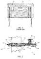
- U.S. Pat. No. 5,369,277 issued to Knodle et al.discloses an exemplary infrared source, as shown in FIG. 1 .
- Mirror 10collimates the emitted infrared radiation source rays from infrared radiation source 20 and focuses the collimated rays into a beam that is directed along the optical path of the device.
- the infrared source rayspass through an optical aperture containing an infrared transmissive window, enter one end of the sample cell, and those that are parallel, or nearly parallel, i.e. having a small angle relative to parallel, to the axis of the optical path through the sample cell, pass out the aperture at the other end of the sample cell into the detector.
- rays that enter at a larger angle relative to the axis of the optical pathmay be stopped by the aperture at the detector end of the cell.
- the length to cross section ratiois large, so that a relatively small number of rays are able to get though to the detector.
- This objectis achieved according to one embodiment of the present invention by providing a half-ball-type lens in close proximity of the infrared radiation source.
- infrared radiationWhile the use of infrared radiation has been described, the principles of the present invention are also applicable to measurement systems using sources emitting other wavelengths bands including but not limited to visible and ultra-violet radiation.
- FIG. 1is cross-sectional view of a conventional infrared source
- FIG. 2is a schematic diagram of the general optical arrangement for the small tube-type airway adapter according to the principles of the present invention
- FIG. 3is an exploded perspective view of the infrared source of FIG. 2 ;
- FIG. 4is a cross-sectional view of a mainstream transducer including the infrared source of FIG. 2 ;
- FIG. 5Ais a side sectional view of a mainstream neonatal sample cell
- FIG. 5Bis a top sectional view of the mainstream neonatal sample cell of FIG. 5A .
- FIG. 5Cis a side view of the mainstream neonatal sample cell of FIGS. 5A and 5B ;
- FIG. 6Bis a top sectional view of the mainstream pediatric/adult sample of FIG. 6A .
- FIG. 7is a perspective view of a sidestream sample cell receptacle and measurement optics
- FIG. 8is a perspective view of the sample cell body with the sample cell core inserted therein.
- FIG. 9is a cross-sectional view of the sample cell body and sample cell core taken along line 9 — 9 of FIG. 8 .
- the NDIR detector assemblywhich is comprised of a narrow band filter and a detector.
- a DIR systemdoes not use narrow band filters. However, they are subject to a type of “bias” in that a change in angular distribution will change the width of the absorption peak.
- different sized apertureschange the mix of incident angles at the narrow-band filter just before the infrared detector. These filters are typically of the interference type, manufactured to provide a suitably narrow selection of wavelengths for gas measurement.
- Interference filtersconsist of multiple thin layers of dielectric material having different refractive indices and are wavelength-selective by virtue of the interference effects that take place between the incident and reflected rays at the thin-film boundaries.
- the center wavelength of interference filtersshifts toward shorter wavelengths as the angle of incidence of incoming rays increases.
- the result of this shiftis that the average passband of the filter that selects the absorption line for the gas to be measured, such as carbon dioxide, shifts as the average ray incidence angle changes.
- This effectcan be prevented if the optical system is designed such that the angular mix does not change when the airway apertures are changed.
- the systemis designed so that the bundle of rays that are directed to the detector are entirely contained within the smallest apertures of interest, then there is no change if larger apertures are used.
- the present inventionreplaces the mirror assembly in a conventional transducer with a type of hemispherical or spherical lens, known as ball lens or half-ball lens, and reorients the radiation emitter.
- the emitter that had been facing and directing radiation to the mirror in a conventional gas measuring systemis turned around to face the sample cell, with a ball or half-ball lens disposed between the emitter and the sample cell.
- Ball lensesare well known in the telecommunication art for improving signal coupling between optical fibers and emitters and detectors, but not in the gas measurement art.
- a larger diameter lensis used to provide a beam that is much larger than in the pervious optical fiber case, and at the same time, the larger lens makes it possible to reduce the optical magnification while maintaining the numerical aperture (defined for any ray as the sine of the angle made by that ray with the optical axis multiplied by the index of refraction). The result of these changes is a much improved image, i.e., a better collection efficiency, at the detector. Because the beam is smaller than or equal to the smallest aperture of interest, there will be no change in the angular structure of the beam if larger apertures are used. For good emitter efficiency, the lens must have a high numerical aperture on the emitter side.
- lens types manufactured for the mid-IR range, where the absorption of many gases of interest are situatedare expensive. This is the case because either the materials, such as Germanium, CaF, or ZnSe are expensive, or the lens manufacturing process is labor-intensive.
- sapphire ball lenses, in small sizesare relatively inexpensive, because the manufacturing process is similar to that of ball bearings, and they are manufactured in high quantities for various optical, mechanical, and other non-optical purposes. Such manufacturing processes provide excellent surface uniformity, polish, and size accuracy, all a low cost. Therefore, the ball lens approach of the present invention also provides a smaller and lower cost source package, and eliminates the source web, thereby increasing the signal level.
- a ball or half-ballis used to obtain a focal length that is suited for an infrared gas analyzer.
- a problem associated with ball or half-ball lenses with a high numerical apertureis the optical distortion inherent in such lens caused by their spherical shape, known as spherical aberration.
- the result of spherical aberrationis a reduction in the efficiency of the collection of light at the detector. This optical defect is caused when rays of light passing through the curved surface of a lens near its edge converge at a point closer to the lens than those passing through or near its center. These edge light rays would then spread out, thereby missing the detector assembly.
- the reflective walls in the sample cell of the present inventionmay be obtained by coating the walls with aluminum, gold, or other metals that are highly reflective at NIR wavelengths. This can be accomplished, for example, by plating, sputtering, or any other technique known in the art.
- the wall surfacecan also be formed from a high index material.
- the walls in the sample cellcan be formed from a mirror-smooth material, i.e., a material having a smooth surface void of defects, so long as the mirror-smooth material reflects strongly at relatively large incident angles.
- the addition of the light guide function by reflective wallsimproves the detector signal, and, hence improves the signal/noise by several times.
- the rays that bounce one or more timesadd randomness to the light beam, thereby reducing effects of misalignment or asymmetric elements. While this approach does not correct for optical distortion caused by spherical aberration, it compensates for the reduced collection efficiency by bringing the bundle of light rays closer to the detector so that much fewer rays are lost. That is, it improves the collection efficiency, not image quality.
- the present inventioncontemplates forming the light guide in the shape of a “U”, with the source and detector on the same side of the system. The light path would then be double length for the same sample cell thickness, or the sample cell could be made half as thick for the same light path length.
- the present inventionalso contemplates forming the light guide in a “C” shape, with the source and detector placed back-to-back.
- a detector portcan be placed at the bottom of the “U” or at the back of the “C”. This extra port provides a half sensitivity signal for instances where the gas of interest is otherwise so absorptive that meaningful resolution is lost.
- This methodcould also work with other optical designs (for example curved tubes either flexible or rigid) to further optimize flow characteristics without imposing on signal resolution.
- rays entering at a relatively large angle relative to the optical axismay be stopped by the aperture at the detector end of the sample cell.
- the length to cross section ratiois large, so that a relatively small number of rays are able to get though to the detector.
- the present inventioncontemplates that the walls of the cell are made reflective, and the cross section of the cell is made substantially equal to, or smaller than, the detector aperture. With this introduction of reflective walls, all rays that enter the sample cell at an angle that would have been stopped by the detector aperture instead are reflected off the walls at least once, and are thereby guided to pass through the aperture.
- FIG. 2schematically depicts a sample cell 130 with an infrared radiation source assembly 120 and an infrared radiation detector assembly 140 .
- Infrared radiation source 120comprises an emitter 121 and a half-ball lens 122 .
- Emitter 121emits rays of infrared radiation. These rays are collected by half-ball lens 122 and exit in a “parallel” fashion from the lens.
- the raysenter sample cell 130 through an entrance window 131 , which is transmissive in the infrared range, and then passes through a portion of the flow path within the sample cell.
- FIG. 2schematically depicts a sample cell design in which the rays are constrained to a tube 134 having internal walls that are inherently reflective to the rays by the selection of the material forming the walls of the tube.
- a typical light ray bundle 133is shown within the tube. The rays leave the sample cell via an exit window 132 .
- Lens 150is disposed adjacent to exit window 132 .
- Lens 150reduces the size of the ray bundle at the detector, i.e., focuses the rays, so that a relatively large number of rays reach infrared detector assembly 140 thereby improving the detection efficiency, i.e., directs the more divergent light rays into the detector.
- Lens 150has a relatively low numerical aperture, and is inexpensive and has both an optical function and a mechanical function. Mechanically, lens 150 is a flat-surface window that protects the elements of the detector assembly.
- lens 150is a lens that reduces the magnification of the optical system, so that the source image at the detector plane is smaller, i.e., more nearly the size of the detectors, which improves the sensing ability of the detectors. In fact, the image is less than half what it would be without lens 150 .
- magnificationwould be reduced by shortening the source-to-detector distance, but this is not possible in some cases, because a sample cell typically has fixed minimum distance.
- the only other way to reduce magnificationis to increase the emitter to ball lens distance.
- the ball lenswould be larger and cost more, the beam may be too large for the tube aperture so that less emitter light is collected, resulting in an undesirable decrease in the signal output by the detector.
- the infrared detector assemblycomprises a beam splitter 145 that transmits and reflects a portion of the received radiation.
- the received radiation that is transmitted through the beam splitterpasses to a reference band-pass filter 144 and is then measured by a reference detector 142 .
- the received radiation that is reflected by the beam splitterpasses to data band-pass filter 143 and is then measured by a data detector 141 . While a design known as a coaxial configuration is shown, other non-dispersive and dispersive designs may be used with the half-ball lens source and reflective sample cell surfaces.
- FIG. 3is a perspective view of an exemplary source assembly 120 comprising half-ball lens 122 mounted in a lens holder 124 .
- An infrared emitter 121is mounted on commutators 123 and a base 127 is provided into which the other components are placed.
- half ball lensis 1 ⁇ 8 inch in diameter and machined from sapphire. Other sizes of half ball-lens may be used depending upon the optical apertures.
- Circular protrusions in base 127provide alignment of commutators 123 with the base.
- Leads 125 and 126provide the electrical interface to the emitter.
- FIG. 4depicts a cross-sectional view of an exemplary mainstream gas analyzer transducer 137 with a coaxial NDIR detector assembly 139 utilizing the source assembly of FIGS. 2 and 3 .
- a housing 155contains source assembly 120 and detector assembly 139 .
- the source assemblyincludes half ball lens 122 , lens holder 124 , infrared emitter 121 , and base 127 .
- the detector assemblyincludes reference and data detectors 141 and 142 , respectively, reference and data filters 143 and 144 , respectively, beamsplitter 145 and mirror 146 . As generally illustrated by the arrows in FIG.
- infrared radiation emanating from source assembly 120passes through the windows and the sample chamber of a sample cell that has been secured within a recess 147 . After having passed through the sample cell, the radiation is split by beam splitter 145 so that radiation is directed to reference and data detectors 141 and 142 . Signals from reference and data detectors 141 and 142 are amplified, filtered, and processed by electronics located in the transducer and communicated to a host system (not shown). Exemplary sample cells that are adapted to be removably securable to mainstream gas analyzer transducer 137 are described in U.S. Pat. Nos. 5,693,944, and 5,616,923 to Rich et al. and shown in FIGS. 5A–6C .
- the sample cellincludes a transducer mounting recesses 163 a and 163 b ( FIG. 5B) and 175 a and 175 b ( FIG. 6B ) provided on opposite sides of the sample cell.
- Such transducer mounting recessesprovide a support surface for the transducer on the sample cell and serve to correctly align the optical components in the transducer with the sample cell.
- FIGS. 5A–5C and 6 A– 6 Cdepict mainstream sample cells with different optical apertures that are capable of being securably and removably coupled with mainstream gas analyzer transducer 137 of FIG. 4 .
- mainstream sample cellsare molded to close tolerances because the intensity of the infrared radiation impinging upon the infrared radiation detector is dependent upon the length of the optical path between radiation source and detector, and the length of that path is controlled by the width of the sample cell. Consequently, unless close tolerances are maintained, calibration of each individual sample cell would be required, which is impractical and economically prohibitive.
- sample cells of the illustrated configurationare fabricated from polymers such as polycarbonate and are relatively inexpensive.
- FIGS. 5A–5Cdepict a mainstream low deadspace sample cell 159 primarily used to monitor neonatal patients.
- Sample cell 159includes a first end 164 that connects the sample cell to the patient via an endotracheal tube or other form of patient interface.
- a second end 166 of sample cell 159connects to a breathing circuit.
- the gasflows from second end 166 through the sample cell and exits first end 164 .
- the gasflow from first end 164 through the sample cell and exits second end 166 .
- Windows 162 and 160 located in the optical apertures of the sample cellpermit the infrared radiation to pass through a flow passageway 165 of the sample cell.
- Line 168indicates the centerline of the optical aperture as well as the axis for the optical path for radiation passing through the sample cell.
- the infrared radiation emitted by a radiation sourcepasses through one of the windows and traverses the sample cell substantially normal to the flow of gas within flow passageway 165 before exiting through the window disposed on the opposite side of the sample cell and entering the infrared radiation detector.
- FIGS. 6A–6Cdepict a mainstream sample cell 169 primarily used to monitor pediatric and adult patients.
- Sample cell 169includes a first end 174 that connects the sample cell to the patient via an endotracheal tube or other form of patient interface.
- a second end 176 of sample cell 169typically connects to a breathing circuit.
- the gasflows from second end 176 through the sample cell and exits first end 174 .
- the gasflows from first end 174 through the sample cell and exits second end 176 .
- Windows 172 and 170 located in the optical apertures of the sample cellpermit the infrared radiation to pass through the flow passageway of the sample cell.
- Line 178indicates the centerline of the optical aperture as well as the axis for the optical path for radiation passing through the sample cell.
- the infrared radiation emitted by a radiation sourcepasses through a window and traverses the sample cell along an optical path corresponding to line 178 that is substantially normal to the flow within a flow passageway 179 before exiting through the window disposed on the opposite side of the sample cell and entering the infrared radiation detector.
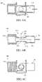
- FIG. 7is a perspective view of a sidestream sample cell receptacle 200 and the gas measurement optics associated therewith.
- Detector assembly 140 and source assembly 120are affixed to sample cell receptacle 200 .
- a sample cell 180is shown in the “latched” or engaged position in the sample cell receptacle, with a protrusion 187 of a latching arm 186 extending from a sample cell securely engaged in a slot defined in sample cell receptacle 200 .
- a sample cell output port(not shown) seats to a seal disposed within an input port 204 attached to the sample cell receptacle.
- Source assembly 120is used in the embodiment shown and comprises the half ball lens, lens holder, infrared emitter, and base.
- FIG. 8schematically illustrates an exemplary embodiment of sample cell 180 according to the principles of the present invention.
- Sample cell 180includes a sample cell body or housing 188 and a sample cell core 189 that is removeably attached within a chamber defined in the sample cell body. Gas from a sampling tubing originating in an airway adapter or nasal cannula is drawn through an optional filter prior to entering sample cell body 180 via an inlet port 184 . Infrared radiation is passed through the gas flowing through sample cell 180 , and a portion of the infrared radiation is absorbed by the gases present in the sample cell. Using an optics configuration coupled to this sample cell, the partial pressure of gases, such as carbon dioxide, can be measured.
- gasessuch as carbon dioxide
- Sample cell 180is optically and mechanically coupled with a radiation source assembly and a radiation detection assembly. The radiation is emitted from source assembly 120 , then passes through sample cell 180 and enters infrared radiation detection assembly 140 .
- Sample cell 180may be positioned either temporarily or permanently within the measurement optics, which includes a radiation source assembly and radiation detector assembly.
- the infrared radiation from source assemblypasses through a window (not shown) of sample cell body 188 into the interior of sample cell core 189 , where a portion of the radiation is absorbed by the gas in the sample cell core.
- the transmitted radiationthen may either pass through another window (not shown) or reflect and pass again through the window.
- a windowmay be secured to sample cell body 189 via a snap-in retainer ring. In either case, a detector assembly eventually converts the transmitted radiation into signals that are sampled and converted into a measured value.
- FIG. 9is a cross-sectional view of the exemplary sample cell 180 taken substantially along line 9 — 9 of FIG. 8 .
- a flow of gas through passages within sample cell body 188 and sample cell core 189are indicated by arrows 198 and 199 . More specifically, gas enters the sample cell after passing through the sampling tubing and an optional filter device to remove fluids before entering the sample cell, as indicated by arrow 199 . After the gas passes through a passage within inlet port 184 , it enters the passage located within the sample cell core 189 .
- sample cell core 189the gas enters a sample chamber 196 via an inlet 194 adjacent to a window 200 at one end of the sample chamber and exits via an outlet 192 adjacent to a window 202 at the opposite end of sample cell chamber 196 .
- Sample cell chamber 196is the portion of the passage in which radiation passes through, and it is the infrared reflectivity of this chambers interior surfaces that enhances the signal received by the infrared detectors.
- Sample chamber 196 in a preferred embodimenthas a cylindrical design, with the inlet and outlet positioned at opposite ends of the sample chamber as close to the windows as possible to permit the sample gas to cleanly pass through the sample cell without crevices and other “unswept” volumes (sometimes referred to as “deadspace”).
- sample cell core 189may be molded from a high index material or sample cell chamber 196 may be plated with a material that is highly reflective at NIR wavelengths. After passing out of sample cell core 189 , the gas exits sample cell 180 after passing through the passage within outlet 182 , as indicated by arrow 198 .
- the sample cell coreis preferably located in the central portion of the sample cell and provides a passage for the gas sample between the symmetrical inlet and outlet passages in the body.
- the optical path of sample cell 180does not simply transverse the flow path, but is parallel with the flow path for a substantial portion of the path length.
- a flow passage shape referred to as the “Z” configurationis used in this exemplary sample cell. This configuration also allows for the uniform flow passage from outside the sample cell, into the sample cell body and sample cell core without unnecessary transitions and the resultant turbulence.
Landscapes
- Health & Medical Sciences (AREA)
- Physics & Mathematics (AREA)
- Life Sciences & Earth Sciences (AREA)
- General Health & Medical Sciences (AREA)
- Pathology (AREA)
- Chemical & Material Sciences (AREA)
- Analytical Chemistry (AREA)
- Biochemistry (AREA)
- General Physics & Mathematics (AREA)
- Immunology (AREA)
- Spectroscopy & Molecular Physics (AREA)
- Physiology (AREA)
- Medical Informatics (AREA)
- Pulmonology (AREA)
- Biophysics (AREA)
- Engineering & Computer Science (AREA)
- Biomedical Technology (AREA)
- Heart & Thoracic Surgery (AREA)
- Obesity (AREA)
- Molecular Biology (AREA)
- Surgery (AREA)
- Animal Behavior & Ethology (AREA)
- Public Health (AREA)
- Veterinary Medicine (AREA)
- Emergency Medicine (AREA)
- Investigating Or Analysing Materials By Optical Means (AREA)
Abstract
Description
Claims (4)
Priority Applications (5)
| Application Number | Priority Date | Filing Date | Title |
|---|---|---|---|
| US10/792,180US7183552B2 (en) | 2003-03-07 | 2004-03-03 | Optical system for a gas measurement system |
| PCT/US2004/006726WO2004081612A2 (en) | 2003-03-07 | 2004-03-04 | Improved optical system for a gas measurement system |
| US11/165,670US7432508B2 (en) | 2003-02-21 | 2005-06-24 | Gas measurement system |
| US11/368,832US7501630B2 (en) | 2003-02-21 | 2006-03-06 | Gas measurement system |
| US12/371,151US8080798B2 (en) | 2003-02-21 | 2009-02-13 | Gas measurement system |
Applications Claiming Priority (2)
| Application Number | Priority Date | Filing Date | Title |
|---|---|---|---|
| US45265603P | 2003-03-07 | 2003-03-07 | |
| US10/792,180US7183552B2 (en) | 2003-03-07 | 2004-03-03 | Optical system for a gas measurement system |
Related Parent Applications (1)
| Application Number | Title | Priority Date | Filing Date |
|---|---|---|---|
| US10/781,382Continuation-In-PartUS6954702B2 (en) | 2003-02-21 | 2004-02-18 | Gas monitoring system and sidestream gas measurement system adapted to communicate with a mainstream gas measurement system |
Related Child Applications (1)
| Application Number | Title | Priority Date | Filing Date |
|---|---|---|---|
| US11/165,670Continuation-In-PartUS7432508B2 (en) | 2003-02-21 | 2005-06-24 | Gas measurement system |
Publications (2)
| Publication Number | Publication Date |
|---|---|
| US20040256560A1 US20040256560A1 (en) | 2004-12-23 |
| US7183552B2true US7183552B2 (en) | 2007-02-27 |
Family
ID=32994459
Family Applications (1)
| Application Number | Title | Priority Date | Filing Date |
|---|---|---|---|
| US10/792,180Expired - LifetimeUS7183552B2 (en) | 2003-02-21 | 2004-03-03 | Optical system for a gas measurement system |
Country Status (2)
| Country | Link |
|---|---|
| US (1) | US7183552B2 (en) |
| WO (1) | WO2004081612A2 (en) |
Cited By (38)
| Publication number | Priority date | Publication date | Assignee | Title |
|---|---|---|---|---|
| US20100051026A1 (en)* | 2008-09-04 | 2010-03-04 | Nellcor Puritan Bennett Llc | Ventilator With Controlled Purge Function |
| US20100108154A1 (en)* | 2008-10-31 | 2010-05-06 | Horiba, Ltd. | Material gas concentration control system |
| US20100208268A1 (en)* | 2009-02-18 | 2010-08-19 | Heikki Haveri | Gas analyzer |
| US20100308105A1 (en)* | 2008-03-17 | 2010-12-09 | Chris Savarese | Golf club apparatuses and methods |
| US20110011400A1 (en)* | 2009-07-16 | 2011-01-20 | Nellcor Puritan Bennett Llc | Wireless, gas flow-powered sensor system for a breathing assistance system |
| US20110126837A1 (en)* | 2009-12-01 | 2011-06-02 | Nellcor Puritan Bennett Llc | Exhalation Valve Assembly With Integrated Filter |
| US20110126832A1 (en)* | 2009-12-01 | 2011-06-02 | Nellcor Puritan Bennett Llc | Exhalation Valve Assembly |
| USD653749S1 (en) | 2010-04-27 | 2012-02-07 | Nellcor Puritan Bennett Llc | Exhalation module filter body |
| US8113062B2 (en) | 2008-09-30 | 2012-02-14 | Nellcor Puritan Bennett Llc | Tilt sensor for use with proximal flow sensing device |
| USD655405S1 (en) | 2010-04-27 | 2012-03-06 | Nellcor Puritan Bennett Llc | Filter and valve body for an exhalation module |
| USD655809S1 (en) | 2010-04-27 | 2012-03-13 | Nellcor Puritan Bennett Llc | Valve body with integral flow meter for an exhalation module |
| US8439037B2 (en) | 2009-12-01 | 2013-05-14 | Covidien Lp | Exhalation valve assembly with integrated filter and flow sensor |
| US8439036B2 (en) | 2009-12-01 | 2013-05-14 | Covidien Lp | Exhalation valve assembly with integral flow sensor |
| US8469030B2 (en) | 2009-12-01 | 2013-06-25 | Covidien Lp | Exhalation valve assembly with selectable contagious/non-contagious latch |
| US8720442B2 (en) | 2008-09-26 | 2014-05-13 | Covidien Lp | Systems and methods for managing pressure in a breathing assistance system |
| US9629971B2 (en) | 2011-04-29 | 2017-04-25 | Covidien Lp | Methods and systems for exhalation control and trajectory optimization |
| US9649458B2 (en) | 2008-09-30 | 2017-05-16 | Covidien Lp | Breathing assistance system with multiple pressure sensors |
| US9950135B2 (en) | 2013-03-15 | 2018-04-24 | Covidien Lp | Maintaining an exhalation valve sensor assembly |
| CN109563781A (en)* | 2016-06-17 | 2019-04-02 | 法国大陆汽车公司 | For measuring the method and associated measuring device of the pressure for the compressed fuel gas being provided in the supply line of the engine of motor vehicles |
| US10842427B2 (en) | 2005-09-30 | 2020-11-24 | Intuity Medical, Inc. | Body fluid sampling arrangements |
| US10980967B2 (en) | 2012-04-05 | 2021-04-20 | Fisher & Paykel Healthcare Limited | Respiratory assistance apparatus |
| US11002743B2 (en) | 2009-11-30 | 2021-05-11 | Intuity Medical, Inc. | Calibration material delivery devices and methods |
| US11045125B2 (en) | 2008-05-30 | 2021-06-29 | Intuity Medical, Inc. | Body fluid sampling device-sampling site interface |
| US11051734B2 (en) | 2011-08-03 | 2021-07-06 | Intuity Medical, Inc. | Devices and methods for body fluid sampling and analysis |
| DE102021111431A1 (en) | 2020-06-29 | 2021-12-30 | Dräger Safety AG & Co. KGaA | Surveillance system |
| US11399744B2 (en) | 2008-06-06 | 2022-08-02 | Intuity Medical, Inc. | Detection meter and mode of operation |
| US11419532B2 (en) | 2005-06-13 | 2022-08-23 | Intuity Medical, Inc. | Analyte detection devices and methods with hematocrit/volume correction and feedback control |
| US11433210B2 (en) | 2014-05-27 | 2022-09-06 | Fisher & Paykel Healthcare Limited | Gases mixing and measuring for a medical device |
| US11666720B2 (en) | 2015-12-02 | 2023-06-06 | Fisher & Paykel Healthcare Limited | Flow path sensing for flow therapy apparatus |
| DE102022110302A1 (en) | 2022-04-28 | 2023-11-02 | Drägerwerk AG & Co. KGaA | Gas measuring device for determining the concentration of at least one gas component in a breathing gas mixture |
| US11986293B2 (en) | 2008-06-06 | 2024-05-21 | Intuity Medical, Inc. | Medical diagnostic devices and methods |
| US11986298B2 (en) | 2005-09-30 | 2024-05-21 | Intuity Medical, Inc. | Devices and methods for facilitating fluid transport |
| US12005186B2 (en) | 2017-10-06 | 2024-06-11 | Fisher & Paykel Healthcare Limited | Closed loop oxygen control |
| DE102023121409A1 (en) | 2023-08-10 | 2025-02-13 | Dräger Safety AG & Co. KGaA | monitoring system with a gas measuring device |
| WO2025036516A1 (en) | 2023-08-15 | 2025-02-20 | Drägerwerk AG & Co. KGaA | Sensor arrangement having a paramagnetic thermopile sensor and an infrared optical thermopile sensor on a common support |
| DE102024116103A1 (en) | 2023-08-23 | 2025-02-27 | Dräger Safety AG & Co. KGaA | monitoring system with a gas collection device |
| US12292429B2 (en) | 2020-06-29 | 2025-05-06 | Dräger Safety AG & Co. KGaA | Monitoring system |
| US12296095B2 (en) | 2019-09-10 | 2025-05-13 | Fisher & Paykel Healthcare Limited | Methods and systems for controlling oxygen delivery in a flow therapy apparatus |
Families Citing this family (22)
| Publication number | Priority date | Publication date | Assignee | Title |
|---|---|---|---|---|
| US7501630B2 (en)* | 2003-02-21 | 2009-03-10 | Koninklijke Philips Electronics N.V. | Gas measurement system |
| US6954702B2 (en)* | 2003-02-21 | 2005-10-11 | Ric Investments, Inc. | Gas monitoring system and sidestream gas measurement system adapted to communicate with a mainstream gas measurement system |
| US7432508B2 (en)* | 2003-02-21 | 2008-10-07 | Ric Investments, Llc | Gas measurement system |
| US7255474B2 (en)* | 2003-07-28 | 2007-08-14 | Symyx Technologies, Inc. | Parallel infrared spectroscopy apparatus and method |
| CA2589996C (en)* | 2004-12-13 | 2012-02-21 | Bayer Healthcare Llc | Transmission spectroscopy system for use in the determination of analytes in body fluid |
| US8067253B2 (en) | 2005-12-21 | 2011-11-29 | Avery Dennison Corporation | Electrical device and method of manufacturing electrical devices using film embossing techniques to embed integrated circuits into film |
| US8163241B2 (en)* | 2006-05-05 | 2012-04-24 | Dublin City University Dcu | Optical probe |
| DE102006052999B4 (en) | 2006-11-10 | 2014-11-06 | Dräger Medical GmbH | Sample gas cuvette for the concentration measurement of gas components and method for the production of a sample gas cuvette |
| US8197417B2 (en)* | 2008-03-04 | 2012-06-12 | Medical Graphics Corporation | Metabolic analyzer transducer |
| GB2468522B (en)* | 2009-03-12 | 2013-08-07 | Autoliv Dev | A breath analyser |
| CA2856353C (en)* | 2011-12-02 | 2020-03-24 | Senseair Ab | Epoxy molded gas cell for optical measurement and method of forming |
| US9448186B2 (en)* | 2011-12-08 | 2016-09-20 | Gulfstream Aerospace Corporation | System and method for determining a concentration of gas in a confined space |
| US10561863B1 (en) | 2012-04-06 | 2020-02-18 | Orbital Research Inc. | Biometric and environmental monitoring and control system |
| US10786693B1 (en)* | 2012-04-06 | 2020-09-29 | Orbital Research Inc. | Biometric and environmental monitoring and control system |
| DE102014111366A1 (en)* | 2014-08-08 | 2016-02-11 | Peter Ganshorn | Method and device for determining the proportion of molecular oxygen in a respiratory gas |
| EP4293343A3 (en) | 2017-02-28 | 2024-02-28 | Marqmetrix Inc. | Fluid flow cell including a spherical lens |
| AR111876A1 (en)* | 2017-05-17 | 2019-08-28 | Spogen Biotech Inc | DEVICES, SYSTEMS, AND METHODS OF DETECTION OF AGROCHEMICALS AND AGROCHEMICAL COMPOSITIONS |
| IT201700092781A1 (en)* | 2017-08-10 | 2019-02-10 | Maselli Misure S P A | MEASURING INSTRUMENT OF THE CO2 CONCENTRATION WITH A PERFECTED COLLIMATOR |
| KR20200061370A (en) | 2017-09-27 | 2020-06-02 | 쓰리엠 이노베이티브 프로퍼티즈 캄파니 | Personal protective equipment management system using optical patterns for equipment and safety monitoring |
| CN112326554B (en)* | 2019-08-05 | 2023-11-07 | 上海科技大学 | An in-situ infrared micro-reaction cell that controls medium and high temperature and pressure |
| US11480519B2 (en)* | 2020-04-24 | 2022-10-25 | Honeywell International Inc. | Methods, apparatuses, and systems for improving gas detecting devices |
| JPWO2023189628A1 (en)* | 2022-03-30 | 2023-10-05 |
Citations (10)
| Publication number | Priority date | Publication date | Assignee | Title |
|---|---|---|---|---|
| US4622464A (en)* | 1983-11-15 | 1986-11-11 | Fuji Electric Co., Ltd. | Infrared gas analyzer |
| US5282473A (en) | 1992-11-10 | 1994-02-01 | Critikon, Inc. | Sidestream infrared gas analyzer requiring small sample volumes |
| US5341214A (en)* | 1989-09-06 | 1994-08-23 | Gaztech International Corporation | NDIR gas analysis using spectral ratioing technique |
| US5369277A (en) | 1990-05-23 | 1994-11-29 | Ntc Technology, Inc. | Infrared source |
| US5616923A (en) | 1990-05-23 | 1997-04-01 | Novametrix Medical Systems Inc. | Gas analyzer cuvettes |
| US5693944A (en) | 1994-09-02 | 1997-12-02 | Ntc Technology, Inc. | Gas analyzer cuvettes |
| US20010048079A1 (en)* | 2000-06-06 | 2001-12-06 | Massimo Brunamoti | Non-dispersive infrared cell for gas analysis |
| US6369387B1 (en)* | 1999-10-15 | 2002-04-09 | Li-Cor, Inc. | Gas analyzer |
| US6410918B1 (en)* | 1997-10-28 | 2002-06-25 | Edwards Systems Technology, Inc. | Diffusion-type NDIR gas analyzer with improved response time due to convection flow |
| US20020153490A1 (en)* | 2001-03-28 | 2002-10-24 | O'leary Robert | Concentration detection system |
- 2004
- 2004-03-03USUS10/792,180patent/US7183552B2/ennot_activeExpired - Lifetime
- 2004-03-04WOPCT/US2004/006726patent/WO2004081612A2/enactiveApplication Filing
Patent Citations (10)
| Publication number | Priority date | Publication date | Assignee | Title |
|---|---|---|---|---|
| US4622464A (en)* | 1983-11-15 | 1986-11-11 | Fuji Electric Co., Ltd. | Infrared gas analyzer |
| US5341214A (en)* | 1989-09-06 | 1994-08-23 | Gaztech International Corporation | NDIR gas analysis using spectral ratioing technique |
| US5369277A (en) | 1990-05-23 | 1994-11-29 | Ntc Technology, Inc. | Infrared source |
| US5616923A (en) | 1990-05-23 | 1997-04-01 | Novametrix Medical Systems Inc. | Gas analyzer cuvettes |
| US5282473A (en) | 1992-11-10 | 1994-02-01 | Critikon, Inc. | Sidestream infrared gas analyzer requiring small sample volumes |
| US5693944A (en) | 1994-09-02 | 1997-12-02 | Ntc Technology, Inc. | Gas analyzer cuvettes |
| US6410918B1 (en)* | 1997-10-28 | 2002-06-25 | Edwards Systems Technology, Inc. | Diffusion-type NDIR gas analyzer with improved response time due to convection flow |
| US6369387B1 (en)* | 1999-10-15 | 2002-04-09 | Li-Cor, Inc. | Gas analyzer |
| US20010048079A1 (en)* | 2000-06-06 | 2001-12-06 | Massimo Brunamoti | Non-dispersive infrared cell for gas analysis |
| US20020153490A1 (en)* | 2001-03-28 | 2002-10-24 | O'leary Robert | Concentration detection system |
Cited By (61)
| Publication number | Priority date | Publication date | Assignee | Title |
|---|---|---|---|---|
| US11419532B2 (en) | 2005-06-13 | 2022-08-23 | Intuity Medical, Inc. | Analyte detection devices and methods with hematocrit/volume correction and feedback control |
| US11986298B2 (en) | 2005-09-30 | 2024-05-21 | Intuity Medical, Inc. | Devices and methods for facilitating fluid transport |
| US10842427B2 (en) | 2005-09-30 | 2020-11-24 | Intuity Medical, Inc. | Body fluid sampling arrangements |
| US8624738B2 (en)* | 2008-03-17 | 2014-01-07 | Radar Corporation | Golf club apparatuses and methods |
| US20100308105A1 (en)* | 2008-03-17 | 2010-12-09 | Chris Savarese | Golf club apparatuses and methods |
| US11045125B2 (en) | 2008-05-30 | 2021-06-29 | Intuity Medical, Inc. | Body fluid sampling device-sampling site interface |
| US11986293B2 (en) | 2008-06-06 | 2024-05-21 | Intuity Medical, Inc. | Medical diagnostic devices and methods |
| US11399744B2 (en) | 2008-06-06 | 2022-08-02 | Intuity Medical, Inc. | Detection meter and mode of operation |
| US20100051029A1 (en)* | 2008-09-04 | 2010-03-04 | Nellcor Puritan Bennett Llc | Inverse Sawtooth Pressure Wave Train Purging In Medical Ventilators |
| US8528554B2 (en) | 2008-09-04 | 2013-09-10 | Covidien Lp | Inverse sawtooth pressure wave train purging in medical ventilators |
| US20100051026A1 (en)* | 2008-09-04 | 2010-03-04 | Nellcor Puritan Bennett Llc | Ventilator With Controlled Purge Function |
| US8720442B2 (en) | 2008-09-26 | 2014-05-13 | Covidien Lp | Systems and methods for managing pressure in a breathing assistance system |
| US9649458B2 (en) | 2008-09-30 | 2017-05-16 | Covidien Lp | Breathing assistance system with multiple pressure sensors |
| US8113062B2 (en) | 2008-09-30 | 2012-02-14 | Nellcor Puritan Bennett Llc | Tilt sensor for use with proximal flow sensing device |
| US8459290B2 (en)* | 2008-10-31 | 2013-06-11 | Horiba, Ltd. | Material gas concentration control system |
| US20100108154A1 (en)* | 2008-10-31 | 2010-05-06 | Horiba, Ltd. | Material gas concentration control system |
| TWI484310B (en)* | 2008-10-31 | 2015-05-11 | Horiba Ltd | Material gas concertration control system |
| US8194249B2 (en)* | 2009-02-18 | 2012-06-05 | General Electric Company | Gas analyzer |
| US20100208268A1 (en)* | 2009-02-18 | 2010-08-19 | Heikki Haveri | Gas analyzer |
| US20110011400A1 (en)* | 2009-07-16 | 2011-01-20 | Nellcor Puritan Bennett Llc | Wireless, gas flow-powered sensor system for a breathing assistance system |
| US8776790B2 (en) | 2009-07-16 | 2014-07-15 | Covidien Lp | Wireless, gas flow-powered sensor system for a breathing assistance system |
| US11933789B2 (en) | 2009-11-30 | 2024-03-19 | Intuity Medical, Inc. | Calibration material delivery devices and methods |
| US11002743B2 (en) | 2009-11-30 | 2021-05-11 | Intuity Medical, Inc. | Calibration material delivery devices and methods |
| US8469030B2 (en) | 2009-12-01 | 2013-06-25 | Covidien Lp | Exhalation valve assembly with selectable contagious/non-contagious latch |
| US9205221B2 (en) | 2009-12-01 | 2015-12-08 | Covidien Lp | Exhalation valve assembly with integral flow sensor |
| US8469031B2 (en) | 2009-12-01 | 2013-06-25 | Covidien Lp | Exhalation valve assembly with integrated filter |
| US8439036B2 (en) | 2009-12-01 | 2013-05-14 | Covidien Lp | Exhalation valve assembly with integral flow sensor |
| US9987457B2 (en) | 2009-12-01 | 2018-06-05 | Covidien Lp | Exhalation valve assembly with integral flow sensor |
| US8439037B2 (en) | 2009-12-01 | 2013-05-14 | Covidien Lp | Exhalation valve assembly with integrated filter and flow sensor |
| US20110126832A1 (en)* | 2009-12-01 | 2011-06-02 | Nellcor Puritan Bennett Llc | Exhalation Valve Assembly |
| US20110126837A1 (en)* | 2009-12-01 | 2011-06-02 | Nellcor Puritan Bennett Llc | Exhalation Valve Assembly With Integrated Filter |
| USD655809S1 (en) | 2010-04-27 | 2012-03-13 | Nellcor Puritan Bennett Llc | Valve body with integral flow meter for an exhalation module |
| USD655405S1 (en) | 2010-04-27 | 2012-03-06 | Nellcor Puritan Bennett Llc | Filter and valve body for an exhalation module |
| USD653749S1 (en) | 2010-04-27 | 2012-02-07 | Nellcor Puritan Bennett Llc | Exhalation module filter body |
| US10850056B2 (en) | 2011-04-29 | 2020-12-01 | Covidien Lp | Methods and systems for exhalation control and trajectory optimization |
| US11638796B2 (en) | 2011-04-29 | 2023-05-02 | Covidien Lp | Methods and systems for exhalation control and trajectory optimization |
| US9629971B2 (en) | 2011-04-29 | 2017-04-25 | Covidien Lp | Methods and systems for exhalation control and trajectory optimization |
| US11051734B2 (en) | 2011-08-03 | 2021-07-06 | Intuity Medical, Inc. | Devices and methods for body fluid sampling and analysis |
| US11382544B2 (en) | 2011-08-03 | 2022-07-12 | Intuity Medical, Inc. | Devices and methods for body fluid sampling and analysis |
| US11672452B2 (en) | 2011-08-03 | 2023-06-13 | Intuity Medical, Inc. | Devices and methods for body fluid sampling and analysis |
| US12296103B2 (en) | 2012-04-05 | 2025-05-13 | Fisher & Paykel Healthcare Limited | Respiratory assistance apparatus |
| US10980967B2 (en) | 2012-04-05 | 2021-04-20 | Fisher & Paykel Healthcare Limited | Respiratory assistance apparatus |
| US11918748B2 (en) | 2012-04-05 | 2024-03-05 | Fisher & Paykel Healthcare Limited | Respiratory assistance apparatus |
| US9950135B2 (en) | 2013-03-15 | 2018-04-24 | Covidien Lp | Maintaining an exhalation valve sensor assembly |
| US12053585B2 (en) | 2014-05-27 | 2024-08-06 | Fisher & Paykel Healthcare Limited | Gases mixing and measuring for a medical device |
| US11433210B2 (en) | 2014-05-27 | 2022-09-06 | Fisher & Paykel Healthcare Limited | Gases mixing and measuring for a medical device |
| US11666720B2 (en) | 2015-12-02 | 2023-06-06 | Fisher & Paykel Healthcare Limited | Flow path sensing for flow therapy apparatus |
| US20190178175A1 (en)* | 2016-06-17 | 2019-06-13 | Continental Automotive France | Method for measuring the pressure of a compressed gaseous fuel in a supply line of an engine equipping a motor vehicle and associated measuring device (as amended) |
| CN109563781A (en)* | 2016-06-17 | 2019-04-02 | 法国大陆汽车公司 | For measuring the method and associated measuring device of the pressure for the compressed fuel gas being provided in the supply line of the engine of motor vehicles |
| US11359560B2 (en)* | 2016-06-17 | 2022-06-14 | Continental Automotive France | Method for measuring the pressure of a compressed gaseous fuel in a supply line of an engine equipping a motor vehicle and associated measuring device |
| CN109563781B (en)* | 2016-06-17 | 2022-03-08 | 法国大陆汽车公司 | Method for measuring the pressure of compressed gaseous fuel in a supply line equipped to an engine of a motor vehicle and associated measuring device |
| US12005186B2 (en) | 2017-10-06 | 2024-06-11 | Fisher & Paykel Healthcare Limited | Closed loop oxygen control |
| US12296095B2 (en) | 2019-09-10 | 2025-05-13 | Fisher & Paykel Healthcare Limited | Methods and systems for controlling oxygen delivery in a flow therapy apparatus |
| WO2022002555A1 (en) | 2020-06-29 | 2022-01-06 | Dräger Safety AG & Co. KGaA | Monitoring system |
| US12292429B2 (en) | 2020-06-29 | 2025-05-06 | Dräger Safety AG & Co. KGaA | Monitoring system |
| DE102021111431A1 (en) | 2020-06-29 | 2021-12-30 | Dräger Safety AG & Co. KGaA | Surveillance system |
| DE102022110302A1 (en) | 2022-04-28 | 2023-11-02 | Drägerwerk AG & Co. KGaA | Gas measuring device for determining the concentration of at least one gas component in a breathing gas mixture |
| DE102023121409A1 (en) | 2023-08-10 | 2025-02-13 | Dräger Safety AG & Co. KGaA | monitoring system with a gas measuring device |
| WO2025036516A1 (en) | 2023-08-15 | 2025-02-20 | Drägerwerk AG & Co. KGaA | Sensor arrangement having a paramagnetic thermopile sensor and an infrared optical thermopile sensor on a common support |
| DE102023121741A1 (en) | 2023-08-15 | 2025-02-20 | Drägerwerk AG & Co. KGaA | sensor arrangement |
| DE102024116103A1 (en) | 2023-08-23 | 2025-02-27 | Dräger Safety AG & Co. KGaA | monitoring system with a gas collection device |
Also Published As
| Publication number | Publication date |
|---|---|
| US20040256560A1 (en) | 2004-12-23 |
| WO2004081612A3 (en) | 2005-10-20 |
| WO2004081612A2 (en) | 2004-09-23 |
Similar Documents
| Publication | Publication Date | Title |
|---|---|---|
| US7183552B2 (en) | Optical system for a gas measurement system | |
| US12092571B2 (en) | Solid-state spectrometer | |
| US8642966B2 (en) | Gas analyzer for measuring at least two components of a gas | |
| FI91021B (en) | Apparatus for the identification of gases and measurement of the content and method for the identification of gases | |
| US5932877A (en) | High performance side stream infrared gas analyzer | |
| US7294839B2 (en) | Low volume sample cell and gas monitoring system using same | |
| US20040241736A1 (en) | Analyte determinations | |
| EP1332346B1 (en) | Respiratory gas analyzer | |
| US5610400A (en) | Spectroscopic measuring sensor for the analysis of mediums | |
| EP1482301B1 (en) | NDIR multigas analyzer | |
| WO2007002389A2 (en) | Gas measurement system | |
| US6512230B1 (en) | Method and an arrangement for initiating radiation absorption measurements of gaseous media | |
| JPS5818094B2 (en) | Device for measuring CO↓2 content in breathing air | |
| CN105266824A (en) | Non-invasive blood glucose monitoring device and method and analysis method of biochemical molecules | |
| US6534769B1 (en) | Low cost main stream gas analyzer system | |
| US4475813A (en) | Divergent light optical systems for liquid chromatography | |
| US5931161A (en) | On-airway respiratory gas monitor employing transformed infrared signals | |
| US20120190997A1 (en) | Main stream gas analyzing device | |
| US7227642B2 (en) | Absorbance monitor | |
| US8194249B2 (en) | Gas analyzer | |
| US11366056B2 (en) | Respiratory gas analyzer and a beam splitter therefor | |
| CN116297285A (en) | Infrared multicomponent gas detection device | |
| CN116973327A (en) | Gas measuring device for determining the concentration of at least one gas component in a breathing gas mixture | |
| FI101428B (en) | Small non-dispersive gas measuring sensor |
Legal Events
| Date | Code | Title | Description |
|---|---|---|---|
| AS | Assignment | Owner name:RIC INVESTMENTS, INC., DELAWARE Free format text:ASSIGNMENT OF ASSIGNORS INTEREST;ASSIGNOR:RUSSELL, JAMES T.;REEL/FRAME:015197/0558 Effective date:20040322 | |
| AS | Assignment | Owner name:RIC INVESTMENTS, LLC.,DELAWARE Free format text:CHANGE OF NAME;ASSIGNOR:RIC INVESTMENTS, INC.;REEL/FRAME:016715/0109 Effective date:20040317 Owner name:RIC INVESTMENTS, LLC., DELAWARE Free format text:CHANGE OF NAME;ASSIGNOR:RIC INVESTMENTS, INC.;REEL/FRAME:016715/0109 Effective date:20040317 | |
| STCF | Information on status: patent grant | Free format text:PATENTED CASE | |
| REMI | Maintenance fee reminder mailed | ||
| FPAY | Fee payment | Year of fee payment:4 | |
| SULP | Surcharge for late payment | ||
| FPAY | Fee payment | Year of fee payment:8 | |
| MAFP | Maintenance fee payment | Free format text:PAYMENT OF MAINTENANCE FEE, 12TH YEAR, LARGE ENTITY (ORIGINAL EVENT CODE: M1553); ENTITY STATUS OF PATENT OWNER: LARGE ENTITY Year of fee payment:12 | |
| AS | Assignment | Owner name:PHILIPS RS NORTH AMERICA LLC, PENNSYLVANIA Free format text:CHANGE OF NAME;ASSIGNOR:RESPIRONICS, INC.;REEL/FRAME:062902/0629 Effective date:20201027 |