US7182729B2 - Surgical retractor with removable scissor arms - Google Patents
Surgical retractor with removable scissor armsDownload PDFInfo
- Publication number
- US7182729B2 US7182729B2US10/943,520US94352004AUS7182729B2US 7182729 B2US7182729 B2US 7182729B2US 94352004 AUS94352004 AUS 94352004AUS 7182729 B2US7182729 B2US 7182729B2
- Authority
- US
- United States
- Prior art keywords
- blade
- retractor
- collar
- collar arm
- blades
- Prior art date
- Legal status (The legal status is an assumption and is not a legal conclusion. Google has not performed a legal analysis and makes no representation as to the accuracy of the status listed.)
- Expired - Lifetime
Links
- 230000008878couplingEffects0.000claimsdescription6
- 238000010168coupling processMethods0.000claimsdescription6
- 238000005859coupling reactionMethods0.000claimsdescription6
- 238000004891communicationMethods0.000claimsdescription4
- 230000002093peripheral effectEffects0.000claimsdescription4
- 210000001519tissueAnatomy0.000description16
- 239000000463materialSubstances0.000description14
- 238000000034methodMethods0.000description13
- 238000001356surgical procedureMethods0.000description6
- 238000003780insertionMethods0.000description5
- 230000037431insertionEffects0.000description5
- 238000013519translationMethods0.000description5
- 210000003205muscleAnatomy0.000description4
- 230000000712assemblyEffects0.000description3
- 238000000429assemblyMethods0.000description3
- 230000006835compressionEffects0.000description3
- 238000007906compressionMethods0.000description3
- 238000012800visualizationMethods0.000description3
- XAGFODPZIPBFFR-UHFFFAOYSA-NaluminiumChemical compound[Al]XAGFODPZIPBFFR-UHFFFAOYSA-N0.000description2
- 229910052782aluminiumInorganic materials0.000description2
- 230000008901benefitEffects0.000description2
- 229910010293ceramic materialInorganic materials0.000description2
- 230000006378damageEffects0.000description2
- 230000000916dilatatory effectEffects0.000description2
- 238000006073displacement reactionMethods0.000description2
- 208000014674injuryDiseases0.000description2
- 229920002379silicone rubberPolymers0.000description2
- 239000004945silicone rubberSubstances0.000description2
- 230000007480spreadingEffects0.000description2
- 230000001954sterilising effectEffects0.000description2
- 230000008733traumaEffects0.000description2
- NIXOWILDQLNWCW-UHFFFAOYSA-Nacrylic acid groupChemical groupC(C=C)(=O)ONIXOWILDQLNWCW-UHFFFAOYSA-N0.000description1
- 210000003484anatomyAnatomy0.000description1
- 238000013459approachMethods0.000description1
- 230000008859changeEffects0.000description1
- 239000004020conductorSubstances0.000description1
- 238000010276constructionMethods0.000description1
- 230000008602contractionEffects0.000description1
- 239000013013elastic materialSubstances0.000description1
- 238000005286illuminationMethods0.000description1
- 239000007943implantSubstances0.000description1
- 238000012977invasive surgical procedureMethods0.000description1
- 230000007246mechanismEffects0.000description1
- 238000012986modificationMethods0.000description1
- 230000004048modificationEffects0.000description1
- 230000000399orthopedic effectEffects0.000description1
- 230000035515penetrationEffects0.000description1
- 238000004321preservationMethods0.000description1
- 230000000750progressive effectEffects0.000description1
- 238000011084recoveryMethods0.000description1
- 238000004659sterilization and disinfectionMethods0.000description1
- 238000007920subcutaneous administrationMethods0.000description1
- 230000000451tissue damageEffects0.000description1
- 231100000827tissue damageToxicity0.000description1
Images


Classifications
- A—HUMAN NECESSITIES
- A61—MEDICAL OR VETERINARY SCIENCE; HYGIENE
- A61B—DIAGNOSIS; SURGERY; IDENTIFICATION
- A61B17/00—Surgical instruments, devices or methods
- A61B17/34—Trocars; Puncturing needles
- A61B17/3417—Details of tips or shafts, e.g. grooves, expandable, bendable; Multiple coaxial sliding cannulas, e.g. for dilating
- A61B17/3421—Cannulas
- A—HUMAN NECESSITIES
- A61—MEDICAL OR VETERINARY SCIENCE; HYGIENE
- A61B—DIAGNOSIS; SURGERY; IDENTIFICATION
- A61B17/00—Surgical instruments, devices or methods
- A61B17/02—Surgical instruments, devices or methods for holding wounds open, e.g. retractors; Tractors
- A—HUMAN NECESSITIES
- A61—MEDICAL OR VETERINARY SCIENCE; HYGIENE
- A61B—DIAGNOSIS; SURGERY; IDENTIFICATION
- A61B17/00—Surgical instruments, devices or methods
- A61B17/02—Surgical instruments, devices or methods for holding wounds open, e.g. retractors; Tractors
- A61B17/0206—Surgical instruments, devices or methods for holding wounds open, e.g. retractors; Tractors with antagonistic arms as supports for retractor elements
- A—HUMAN NECESSITIES
- A61—MEDICAL OR VETERINARY SCIENCE; HYGIENE
- A61B—DIAGNOSIS; SURGERY; IDENTIFICATION
- A61B17/00—Surgical instruments, devices or methods
- A61B17/34—Trocars; Puncturing needles
- A61B17/3417—Details of tips or shafts, e.g. grooves, expandable, bendable; Multiple coaxial sliding cannulas, e.g. for dilating
- A61B17/3421—Cannulas
- A61B17/3439—Cannulas with means for changing the inner diameter of the cannula, e.g. expandable
- A—HUMAN NECESSITIES
- A61—MEDICAL OR VETERINARY SCIENCE; HYGIENE
- A61B—DIAGNOSIS; SURGERY; IDENTIFICATION
- A61B17/00—Surgical instruments, devices or methods
- A61B17/00234—Surgical instruments, devices or methods for minimally invasive surgery
- A61B2017/00238—Type of minimally invasive operation
- A61B2017/00261—Discectomy
Definitions
- the present inventionrelates to a device used to retract tissue within the body of a patient. More specifically, the present invention relates to a retractor that facilitates enlarging a surgical cavity and providing a work-through channel to the surgical site.
- the present minimally invasive approachfacilitates a smaller incision, less tissue trauma, and faster patient rehabilitation, as compared to traditional incision and retraction techniques.
- the various embodiments of the present inventionare particularly useful for orthopedic surgery of the spine, but are envisioned to be limitlessly applicable to other surgical techniques and other parts of the body.
- An aspect of the present inventionprovides an apparatus for conducting a less invasive surgical procedure by making a relatively small incision in a patient's skin and forming a larger surgical cavity below the incision.
- the surgical retractorincludes a mount having a frame connected through two translating pivot points to two collar arms, where the two collar arms are attached together at at least one hinge, a pair of blades connected to the collar arms, and an actuator for rotating the two collar arms along the hinge axis, thereby displacing the blades.
- the actuatoris located close to the hinge connecting the collar arms, and is not a separate instrument.
- the actuatoris at an angle relative to the frame in order to provide clearance with the patient's skin when the axis of the retractor is not perpendicular to the skin.
- Another aspect of the present inventionprovides that at least a portion of the actuator is part of the frame.
- One aspect of the actuatorincludes a screw threadably associated with a housing that is part of the frame.
- the screwwhen the screw is turned, or actuated, it moves distally and bears on both collar arms, thus pushing them downwardly and forcing the blades to open.
- the actuatorfurther includes a ball in communication with the screw and in communication with a hinge pin linking the collar arms together.
- a guidemay be attached to the pin, wherein the guide provides a contact surface for the ball.
- Yet another preferred aspect of the inventionincludes a tool, such as a screwdriver or an Allan key, that engages the actuator to move the actuator and thus cause the blades to move, either to separate or to come together.
- a toolsuch as a screwdriver or an Allan key
- the mountis preferably situated above the skin of the patient and has an opening therethrough allowing entry into the surgical cavity.
- the mountcomprises two collar arms attached at two hinge points.
- the mountincludes an opening through its center leading to a channel, whereby a portion of the opening resides on each of the two collar arms.
- the openingis of an oval cross-section.
- this openingcan be of any diameter, shape, or cross-sectional area.
- the mountcan be of any size or shape and the opening in the mount may or may not correspond to the shape of the tube created by the blades that are attached to the collar arms.
- the bladesare curved, whereby together, they form an oval tube when in a non-expanded position. Upon rotation of the collar arms, the blades move outwardly, thereby displacing tissue and enlarging the surgical cavity.
- the major and minor diameters of the oval tubecan be of any size.
- the bladescan be of any shape and may or may not correspond to the shape of the mount. For example, the curvature of the blade may differ from that of the opening.
- the bladescan be of any length thereby creating surgical cavities with different depths. Additionally, the blades have tapered ends which facilitate progressive tissue penetration. This allows for improved control during insertion and less damage to the tissue.
- Another aspect of the present inventionfurther provides blades that are easily detachable from the mount.
- the bladesare attached to the mount through the use of male and female connectors. These connectors facilitate easily attaching and detaching the blades from the mount.
- the bladesmay be attached by compressing them to fit within the opening, and then allowing them to spring back to original shape and engage the respective connectors. Detachment may be similarly achieved by compressing the blades to disassociate the respective connectors, thereby freeing the blades for removal and/or replacement.
- Other connection configurationsare also envisioned.
- the bladesmay be constructed of any sturdy material, and preferably from a radiolucent or semi-radiolucent material.
- a radiolucent or semi-radiolucent materialIn a preferred embodiment, thin, semi-radiolucent aluminum is employed. This allows for improved visualization of the surgical site when viewed on an X-ray with the retractor in place.
- a non-autoclavable or non-sterilizable materialmay also be utilized.
- the blades, as well as the collar,may also be constructed of a light-conducting material, such as acrylic, for example.
- a cabletransfers light from a light source to the collar and blades, which then illuminate the working space.
- the bladesare easily interchangeable. This allows for quick changes in length, depth, or shape of the blades depending upon a particular surgical situation. Thus, among other advantages, the desired length, depth, or shape of blades can be changed without having to utilize an entirely new device.
- the bladescan be disposable, either in addition to the interchangeable feature, or independent of that feature.
- the bladesmay be removable for disposability, or the blades and the collar to which they are connected may be disposable. Preferred methods contemplate the interchangeability, illumination and/or the disposability features in various forms.
- Another aspect of the present inventionfurther provides a sheath that covers the blades.
- the sheathexpands when the blades are extended outwardly thereby creating an enlarged surgical cavity that is enclosed by the retractor and sheath.
- the sheathalso contracts along with the inward retraction of the blades.
- the sheathis constructed of pliable elastic material, such as silicone rubber, thereby allowing for both its expansion and contraction. It is envisioned that the sheath can be made of any material and can be any length, thickness, or shape, as well as transparency or opaqueness. In a preferred embodiment, the sheath fits snuggly over the blades in both the retracted and expanded positions.
- the sheath materialcan be such that it facilitates easy assembly onto, and removal from, the blades.
- the sheathmay also be disposable, and a preferred method contemplates such disposability. Additionally, the sheath may cover any portion of the blades up to and including their entire surface area.
- the barfor use with the retractor.
- the barcan be easily attached to a rigid, relatively fixed object on a first end and to the retractor on a second end.
- the baris used to hold the retractor in position relative to the patient.
- Multiple barsmay also be interconnected, thus forming a support assembly, to allow for discreet positioning of two or more retractors relative to each other.
- a support assemblyis the AF400 SpineTract System manufactured by Omni-Tract Surgical, a division of Minnesota Scientific. However, any type of bar or assembly can be used.
- the apparatusincludes a guide and a variable number of dilators, whereby the first dilator fit over the guide and subsequent dilators of increasing size are sequentially fit over one another.
- the dilatorsare oval tubes having major and minor inside and outside diameters. Increasingly sized dilators are configured such that each larger dilator can fit over a smaller dilator.
- the guideis inserted in an incision in the skin of the patient. Then a first dilator is moved down the guide thereby increasing the size of the surgical cavity.
- the first dilatorhas outside major and minor diameters which are slightly smaller than the inside major and minor diameters of the second dilator.
- the second dilatoris then slid over the first dilator, thereby once again increasing the size of the surgical cavity. These steps are repeated until the desired surgical cavity size is achieved with a corresponding sized dilator, at which point the retractor, in its closed form, may be inserted into the surgical cavity over the largest dilator, the dilators removed therefrom, and the retractor expanded to further enlarge the surgical cavity below the incision.
- Yet another aspect of the present inventionfurther provides a surgical retractor having a mount and blades as described previously.
- the bladesWith the mount in an unexpanded state, the blades form a tube having an opening extending through the mount.
- This tubehas an inside cross-sectional shape larger than that of the largest dilator. This allows for the retractor to be placed over the largest dilator and into the enlarged surgical cavity.
- the opening in the mount, the tube formed by the blades of the retractor, and the dilatorsare all of an oval cross-sectional configuration. However, it is recognized that other shapes and sizes are possible.
- a preferred methodincludes making an incision in the skin of a patient, securing the guide to a portion of the patient, moving a first smaller sized dilator over the guide to expand tissue, adding further increasingly sized dilators over one another and progressively dilating the incision until the desired surgical cavity size is achieved with a correspondingly sized dilator, sliding the retractor over the largest inserted dilator, removing all of the dilators through the retractor, and by using the actuator, rotating the two collar arms of the mount along the hinge axis thereby displacing the blades laterally and moving the patient's tissue to enlarge a surgical cavity.
- the guide, and all but the largest dilatormay first be removed from the cavity prior to insertion of the retractor. The amount of rotation of the collar arms of the mount along the hinge axis determines the enlargement of the surgical
- Another aspect of the present inventionfurther provides for a method wherein the blades of the retractor are first covered with a sheath before they are introduced into the body of the patient.
- the sheathallows the retractor to form a surgical cavity enclosed by the apparatus. This, in turn, allows for better use of the surgical cavity as surrounding tissue can be prevented from entering the cavity. It is also noted that the sheath may be transparent thus allowing visualization of the expanded cavity outside of the sheath.
- Another aspect of the present inventionfurther provides for a method wherein, prior to displacing the blades of the retractor, a rod is connected to a rigid, relatively fixed object on the rod's first end, and to the retractor on the rod's second end. This step allows for enhanced control of the retractor before and after it is inserted into the body of the patient.
- Another aspect of the present inventionfurther provides that the retractor be inserted into the body of a patient so that the blades of the retractor displace in the same direction in which the muscles run in the area of the incision. This step facilitates minimizing the amount of damage to the muscle tissue upon the expansion of the blades of the retractor.
- Yet another aspect of the present inventionfurther provides for a method for creating a surgical cavity in a body wherein, various elements of the present retractor or the entire retractor, are disposable.
- additional steps of removing the retractor and disposing of the entire apparatusare performed.
- additional steps of removing the retractor and disposing of a portion of it, for example, the bladesare performed.
- additional steps of sterilizing a portion of the retractor and attaching a non-autoclavable, or otherwise non-sterilizable portion, to the sterilized portionare performed. Subsequent to use of the retractor, the non-autoclavable, or otherwise non-sterilizable portion can be disposed.
- kitsincluding the various elements of the present invention.
- the kitcomprises differently sized and shaped mounts, blades, and sheaths.
- the different elementsmay be interchanged to conform to the given surgical situation.
- a methodis contemplated wherein elements of desired shape and size are selected and connected to one another to provide a retractor best suited to create the proper surgical cavity.
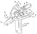
- FIG. 1is a perspective view of one embodiment of the mount portion of the retractor
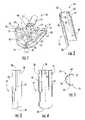
- FIG. 2is a perspective view of a blade of the retractor
- FIG. 3is a side view of the blade of FIG. 2 ;
- FIG. 4is a view of the inside of the blade of FIG. 2 ;
- FIG. 5is a top view of the blade of FIG. 2 ;
- FIG. 6is a perspective view of the retractor in the closed position
- FIG. 7is a perspective view of the retractor in the open position
- FIG. 8is a perspective view of a sheath
- FIG. 9is a perspective view of the retractor in the open position with a sheath around the displaced blades
- FIG. 10is a perspective view of a dilator assembly
- FIG. 11is a perspective view of a retractor in the closed position with a sheath around the blades, placed over the dilator assembly.
- FIG. 12is a perspective view of another embodiment of a mount portion of the retractor.
- FIG. 13is a perspective cut-away view of half of a retractor in the closed position with the mount of FIG. 12 ;
- FIG. 14is a perspective cut-away view of half of a retractor in the open position with the mount of FIG. 12 ;
- FIG. 15is a perspective view of a surgery set-up including a frame assembly supporting two retractors.
- FIG. 1depicts one embodiment of the mount 10 with a first collar arm 11 and a second collar arm 12 rotatable around hinge axis 13 .
- Collar arms 11 and 12are rotatably connected to each other at forward hinge point 14 and rearward hinge point 15 , and connected to frame 19 at first hinge 49 and second hinge 50 .
- first collar arm 11is connected to frame 19 at first hinge 49 by a first hinge pin 52 that extends through a first slot 56 in frame 19 .
- second collar arm 12is connected to frame 19 at second hinge 50 by a second hinge pin 54 that extends through a second slot 57 in frame 19 .
- Hinge points 14 and 15as well as hinges 49 and 50 , allow for the rotational movement of collar arms 11 and 12 .
- slots 56 and 58 on frame 19accommodate hinges 49 and 50 , respectively, and allow for the horizontal translation of hinges 49 and 50 with respect to frame 19 .
- Actuator 17is oriented on frame 19 such that its rotational actuation causes it to translate distally (identified as DT in FIG. 7 ).
- actuator 17acts upon collar arms 11 and 12 causing the rotation of collar arms 11 and 12 around hinge axis 13 , and causing hinge axis 13 , itself, to translate distally.
- Rotation around hinge axis 13is facilitated and accompanied by rotation of collar arms 11 and 12 around hinges 49 and 50 , respectively, as well as translation of hinges 49 and 50 toward the center of frame 19 along slots 56 and 58 , respectfully. All this motion, in turn, causes the expansion of the apparatus.
- Other actuating mechanisms for expanding and contracting the retractor 1are also envisioned.
- Mount channel 18is oval in shape and located centrally between first and second collar arms 11 and 12 .
- Mount channel 18facilitates movement of instruments and other materials into and out of the surgical cavity created by the present invention.
- Mount channel 18further comprises mount connection points 20 , 21 , 22 , and 23 that allow for the connection between collar arms 11 and 12 and blades 24 and 25 ( FIGS. 2 , 3 , and 4 ).
- FIGS. 2–5show views of first blade 24 , which is a mirror image of second blade 25 (shown in FIG. 6 , for example).
- First blade 24has a proximal end 26 , a distal end 36 , an inner portion 68 and a peripheral portion 70 .
- Blade 24also has blade connection points 27 and 28 , hole 72 , rearward slit 64 and forward slit 66 . Additionally, as seen in FIGS. 3 and 4 , the distal end 36 of blade 24 is tapered toward its periphery 70 to facilitate easier insertion through tissue.
- proximal end 26 of blade 24is connected at blade connection points 27 and 28 , as well as at hole 72 , to corresponding connection points 22 and 23 , as well as pin 76 , on first collar arm 11 .
- Blade 24gets connected to collar arm 11 by compressing proximal end 26 , therefore moving blade connection points 27 and 28 toward each other, so as to prepare for assembly with connection points 22 and 23 on collar arm 11 .
- Slits 64 and 66facilitate this compression. It is recognized that compression of points 27 and 28 may be achieved by other configurations, and/or in other ways as well.
- proximal end 26is released from compression, blade 24 regains its original shape and firmly attaches to collar arm 11 through connections 27 to 22 , 28 to 23 , and 72 to 76 .
- the male/female relationship of these connections, as well as the friction fit,allows the blade 24 to remain attached to the first collar arm 11 upon release of the compressive force that had been applied to the proximal end of blade 24 .
- first blade 24is a mirror image of second blade 25 , it is understood that the above description equally applies to the connection of second blade 25 to second collar arm 12 . It is further recognized that many other connection configurations from the ones described above are possible. Such configurations may permit for interchangeability of blades 24 and 25 , or just the removability of the blades for sterilization or disposability. Interchangeability allows a surgeon to readily change blades 24 and 25 depending upon, for example, the desired surgical cavity depth and/or cross-sectional area. Thus a surgeon may be provided with a kit of variably sized and shaped blades from which desired blades may be selected for a particular surgery or technique. Additionally, disposability of the blades allows for easier post-use handling techniques.
- FIG. 5shows a top view of first blade 24 where the blade's curvature is readily apparent.
- blades 24 and 25form a tube that is open at both the proximal and distal ends, with an oval channel therebetween.
- FIG. 6this is the case when actuator 17 has not been translated distally and collar arms 11 and 12 have, therefore, not been rotated around hinge axis 13 .
- Actuator 17comprises a screw 60 that is threadably assembled in housing 62 , which is part of frame 19 .
- housing 62which is part of frame 19 .
- collar arms 11 and 12rotate around hinge axis 13 as hinge axis 13 is moved distally.
- first collar arm 11rotates in direction r 1 around first hinge 49 as hinge 49 translates in direction t 1 in slot 56 ( FIG. 1 )
- second collar arm 12rotates in direction r 2 around second hinge 50 as hinge 50 translates in direction t 2 in slot 58 ( FIG. 1 ).
- blades 24 and 25are displaced in respective retraction directions R 1 and R 2 , and retractor 1 is opened.
- blades 24 and 25spreads apart tissue within the original incision and creates a larger surgical cavity, allowing for a larger working space for a surgeon. Additionally, as shown in FIGS. 3 and 6 , for example, the distal ends 36 of blades 24 and 25 are tapered so as to allow easier insertion into the body of a patient.
- the screw 60may be engaged by a tool, such as screwdriver or an Allan key, to cause it to turn. Additionally, it is envisioned that multiple variations of the type of tool, interface with the screw, as well as screw types, or even the absence of a screw, are possible to accomplish moving the blades of the retractor towards and away from each other.
- a toolsuch as screwdriver or an Allan key
- the material used in the construction of blades 24 and 25is generally of a rigid type to support the spreading of the body tissue, such as aluminum, for example.
- the materialis radiolucent or semi-radiolucent thereby allowing for the improved visualization of the anatomy when viewed on an X-ray with the retractor 1 in place.
- the materialmay be non-autoclavable or otherwise non-sterilizable, and disposable. This further allows for the interchangeability of blades 24 and 25 , to suit a particular surgical cavity.
- FIG. 8shows an embodiment of a sheath 29 of the present invention.
- Sheath 29is preferably made of a pliable, elastic, and translucent material, such as silicone rubber, and fits snugly around blades 24 and 25 .
- sheath 29is assembled over blades 24 and 25 when the retractor 1 is in the unexpanded condition, such as in FIG. 6 .
- sheath 29stretches and forms an enclosure around blades 24 and 25 , as shown in FIG. 9 .
- This enclosureallows for a more manageable surgical cavity by preventing tissue from entering the cavity.
- Sheath 29may also be made of a completely clear material, so that when in the expanded condition, a surgeon may see tissue and objects through sheath 29 when it is in the surgical cavity.
- the sheath 29is sized slightly shorter than the length of the longest vertical peripheral dimension of blades 24 and 25 , as seen in FIG. 3 .
- the distal end of sheath 29stretches over and hooks onto the distal central edges of the blades 24 and 25 , thus preventing the sheath's movement up the blades.
- sheath 29Upon the reverse translation of screw 60 and the return of blades 24 and 25 to their original state, sheath 29 returns to its original form as well.
- the sheathmay aid in bringing blades 24 and 25 back to their original, unexpanded condition. In any event, the tissue surrounding the blades 24 and 25 aids in compressing the blades back to their unexpanded condition.
- various materials with the above desirable properties for the sheath 29may improve the cost-effectiveness of the sheath's 29 disposability.
- the sheath 29may be of any shape or size and may cover any area of the retractor 1 , thereby creating any portion of covered and non-covered areas of blades 24 and 25 .
- FIG. 10shows dilator assembly 30 .
- Dilator assembly 30includes guide 31 and increasingly sized dilators 32 , 33 , 34 , and 35 .
- Each of these dilatorsis a tube with an outside cross-section and an inside cross-section.
- the inside cross-section of each dilatoris slightly larger than the outside cross-section of the next smallest dilator, while the outside cross-section of each dilator is slightly smaller than the inside cross-section of the next largest dilator. This allows for successive dilators to be placed over one another.
- guide 31is inserted through an incision and secured within the body of a patient.
- Dilator 32is then slid over guide 31 into the incision, thereby spreading the incision, and creating a surgical cavity having an area corresponding to the size of the dilator's outside cross-section. This step is repeated with successive dilators 33 , 34 , and 35 until the desired surgical cavity is achieved. It should be noted that any quantity of variously-sized dilators may be used to achieve this surgical cavity. Additionally, the dilators may be of any size or shape as long as they interact with one another as described above and allow the surgical cavity to be created and enlarged.
- retractor 1is inserted over the largest dilator 35 in the cavity. This is done while blades 24 and 25 are together, whereby they form a passage extending distally from mount channel 18 . This passage is large enough to accommodate the largest dilator 35 within it. Additionally, the tapered distal ends 36 of blades 24 and 25 facilitate easier insertion through the tissue.
- retractor 1Once retractor 1 is in place over the largest dilator 35 , the guide 31 and all dilators 32 – 35 are removed from the surgical cavity. This leaves an opening corresponding to the passage extending from the proximal ends 26 to the distal ends 36 of the blades 24 and 25 . Blades 24 and 25 of retractor 1 may then be expanded, thus enlarging the surgical cavity. It is also contemplated that retractor 1 may be inserted into the body in an orientation allowing blades 24 and 25 to displace in the same direction in which the muscles run in the area of the surgical site. Orienting retractor 1 in this fashion helps minimize muscle tissue damage and contributes to a faster recovery time from surgery for the patient. However, retractor 1 may be oriented in any fashion necessary to create a larger surgical cavity, in any area of the body. The introduction of retractor 1 into the body of a patient allows for the preservation of a small portal at the skin's surface.
- FIGS. 12–14show another preferred embodiment of a retractor 2 of the present invention.
- This retractor 2features a different frame 80 and actuator arrangement 90 from frame 19 and actuator 17 of retractor 1 .
- actuator 90comprises a screw 96 threadably engaged in an actuator housing 94 , and a ball 100 within the housing 94 .
- the ball 100rides on a bearing element 106 that resides on hinge pin 102 .
- Hinge pin 102couples the first and second collar arms 11 and 12 together at rearward hinge point 15
- hinge pin 104couples collar arms 11 and 12 together at forward hinge point 14 .
- Both hinge pins, 102 and 104are on the same hinge axis 13 . It is understood, however, that other variations are also possible.
- the housing 94is part of frame 80 , but is oriented at an angle that is other than parallel to hinge axis 13 . Additionally, the exterior 92 of housing 94 is shaped to serve the same function as retractor connection segment 16 of retractor 1 , which is to facilitate coupling the retractor to a support structure that aids in maintaining the position of the retractor in place relative to the patient.
- the proximal interior of housing 92contains a stop ring 98 which serves as a restriction to retraction of screw 96 beyond the proximal end of housing 94 , to prevent screw 96 from being inadvertently removed from housing 94 during the closing of retractor 2 .
- collar arms 11 and 12also have cutouts 82 and 84 , respectfully, which aid in attaching and removing blades 24 and 25 to collar arms 11 and 12 , by providing additional manipulation space for the proximal ends 26 of blades 24 and 25 .
- FIGS. 13 and 14show a cut-away view of half of retractor 2 , where actuator 90 , frame 80 , first collar arm 11 , and first blade 24 are visible.
- FIG. 13shows retractor 2 in the closed position
- FIG. 14shows retractor 2 in the open position.
- screw 96is advanced distally in housing 94 .
- screw 96pushes on ball 100 , which, in turn, pushes on bearing element 106 .
- Bearing element 106is coupled to hinge pin 102 which is part of rearward hinge point 15 .
- Hinge pin 102rotatably joins collar arms 11 and 12 , and hinge point 15 is capable of moving distally.
- ball 100pushes downwardly on bearing element 106 .
- Bearing element 106then moves downwardly together with hinge pin 102 , which causes hinge point 15 to move distally and, therefore, blades 24 and 25 to expand from the closed configuration in FIG. 13 to the open configuration in FIG. 14 .
- the amount of distal movement of hinge point 15is the same as the vertical component of the movement of ball 100 from its position in FIG. 13 to its position in FIG. 14 .
- ball 100moves from an elevated rearward position on bearing element 106 , as shown in FIG. 13 , to a lowered forward position on bearing element 106 , as shown in FIG. 14 .
- ball 100is made of a ceramic material, and has a low-friction surface.
- the ceramic materialis used for the resulting strength of the ball 100 , while the low-friction surface is to diminish the undesirable friction forces associated with the functioning of actuator 90 , which otherwise increase the effort required to open the retractor 2 .
- Bearing element 106 and screw 96may be made of any suitable material, and have any suitable surface finish, to compliment and improve the functionality and compatibility of the retractor 2 , given the above parameters.
- the tip of screw 96 that contacts ball 100may have a low-friction surface to further diminish the frictional forces involved in advancing ball 100 along bearing element 106 .
- FIG. 15shows a typical configuration where one or more retractors are used in conjunction with a support assembly 47 .
- the support assembly 47comprises a first bar 37 connected to a first retractor 43 through a first holder 38 .
- a second bar 44connected to a second retractor 45 through a second holder 46 .
- the first and second barsare joined together at coupling 48 .
- the support assembly 47is ultimately attached to a rigid structure that facilitates maintaining the retractors 43 and 45 in relative position with respect to the patient.
- a support assembly of this typeis the AF400 SpineTract System manufactured by Omni-Tract Surgical, a division of Minnesota Scientific.
- different support assembliescan be used, including but not limited to single support assemblies, where only one retractor is utilized.
- retractor of the present inventionmay be utilized on any part of the patient where a small incision but large subcutaneous operating area is desirable.
- kitsencompassing the various elements disclosed above. This kit may include, but is not limited to, differently sized and shaped mounts 10 , blades 24 and 25 , and sheaths 29 . Any or all of these different elements may be interchanged to suit the desired surgical cavity. Depending upon the conditions, a surgeon may select different mounts 10 , blades 24 and 25 , and sheaths 29 for assembly and use.
Landscapes
- Health & Medical Sciences (AREA)
- Life Sciences & Earth Sciences (AREA)
- Surgery (AREA)
- Heart & Thoracic Surgery (AREA)
- Engineering & Computer Science (AREA)
- Biomedical Technology (AREA)
- Nuclear Medicine, Radiotherapy & Molecular Imaging (AREA)
- Medical Informatics (AREA)
- Molecular Biology (AREA)
- Animal Behavior & Ethology (AREA)
- General Health & Medical Sciences (AREA)
- Public Health (AREA)
- Veterinary Medicine (AREA)
- Pathology (AREA)
- Surgical Instruments (AREA)
Abstract
Description
Claims (13)
Priority Applications (2)
| Application Number | Priority Date | Filing Date | Title |
|---|---|---|---|
| US10/943,520US7182729B2 (en) | 2003-09-18 | 2004-09-17 | Surgical retractor with removable scissor arms |
| US11/652,810US7988625B2 (en) | 2003-09-18 | 2007-01-12 | Surgical retractor with removable scissor arms |
Applications Claiming Priority (3)
| Application Number | Priority Date | Filing Date | Title |
|---|---|---|---|
| US50394403P | 2003-09-18 | 2003-09-18 | |
| US51920203P | 2003-11-12 | 2003-11-12 | |
| US10/943,520US7182729B2 (en) | 2003-09-18 | 2004-09-17 | Surgical retractor with removable scissor arms |
Related Child Applications (1)
| Application Number | Title | Priority Date | Filing Date |
|---|---|---|---|
| US11/652,810DivisionUS7988625B2 (en) | 2003-09-18 | 2007-01-12 | Surgical retractor with removable scissor arms |
Publications (2)
| Publication Number | Publication Date |
|---|---|
| US20050070765A1 US20050070765A1 (en) | 2005-03-31 |
| US7182729B2true US7182729B2 (en) | 2007-02-27 |
Family
ID=34381089
Family Applications (2)
| Application Number | Title | Priority Date | Filing Date |
|---|---|---|---|
| US10/943,520Expired - LifetimeUS7182729B2 (en) | 2003-09-18 | 2004-09-17 | Surgical retractor with removable scissor arms |
| US11/652,810Expired - Fee RelatedUS7988625B2 (en) | 2003-09-18 | 2007-01-12 | Surgical retractor with removable scissor arms |
Family Applications After (1)
| Application Number | Title | Priority Date | Filing Date |
|---|---|---|---|
| US11/652,810Expired - Fee RelatedUS7988625B2 (en) | 2003-09-18 | 2007-01-12 | Surgical retractor with removable scissor arms |
Country Status (5)
| Country | Link |
|---|---|
| US (2) | US7182729B2 (en) |
| EP (1) | EP1662978B1 (en) |
| JP (1) | JP4504376B2 (en) |
| AU (1) | AU2004273967B2 (en) |
| WO (1) | WO2005027726A2 (en) |
Cited By (48)
| Publication number | Priority date | Publication date | Assignee | Title |
|---|---|---|---|---|
| US20040181231A1 (en)* | 2003-03-13 | 2004-09-16 | Centerpulse Spine-Tech, Inc. | Spinal access instrument |
| US20070027364A1 (en)* | 2005-07-28 | 2007-02-01 | Stefan Schwer | Expandable access device |
| US20070118023A1 (en)* | 2002-04-05 | 2007-05-24 | Smith Maurice M | Devices and methods for percutaneous tissue retraction and surgery |
| US20070123753A1 (en)* | 2003-09-18 | 2007-05-31 | Stryker Spine | Surgical retractor with removable scissor arms |
| US20080033251A1 (en)* | 2006-06-30 | 2008-02-07 | Ali Araghi | Surgical retractor and method of use |
| US20080183046A1 (en)* | 2007-01-26 | 2008-07-31 | Wayne Boucher | Surgical retractor with removable blades and method of use |
| US20080183044A1 (en)* | 2007-01-26 | 2008-07-31 | Dennis Colleran | Flexible surgical retractor and method of use |
| US20090018399A1 (en)* | 2004-10-08 | 2009-01-15 | Scot Martinelli | Surgical access system and related methods |
| US20100081885A1 (en)* | 2008-09-30 | 2010-04-01 | Aesculap Implant Systems, Inc. | Tissue retractor system |
| US20100240961A1 (en)* | 2009-03-23 | 2010-09-23 | International Spinal Innovations, Llc | Minimally invasive surgical retractor with an expanded field of vision |
| US20100286486A1 (en)* | 2005-10-17 | 2010-11-11 | Lanx, Inc. | Pedicle guided retractor system |
| US20110009706A1 (en)* | 2009-07-13 | 2011-01-13 | Custom Spine, Inc. | Adjustable Polyaxial Tissue Retractor |
| US20110087074A1 (en)* | 2009-04-03 | 2011-04-14 | Hardenbrook Mitchell A | Surgical retractor system |
| US20110130793A1 (en)* | 2009-11-10 | 2011-06-02 | Nuvasive Inc. | Method and apparatus for performing spinal surgery |
| US20110172494A1 (en)* | 2010-01-12 | 2011-07-14 | Tedan Surgical | Surgical retractor with curved rotating blades |
| US20110184246A1 (en)* | 2007-08-10 | 2011-07-28 | Girius Antanaitis | Surgical retractor |
| US20120277757A1 (en)* | 2011-04-13 | 2012-11-01 | Curax, Llc | Multi-function cannulated surgical device |
| US8636655B1 (en) | 2010-01-19 | 2014-01-28 | Ronald Childs | Tissue retraction system and related methods |
| US8795167B2 (en) | 2011-11-15 | 2014-08-05 | Baxano Surgical, Inc. | Spinal therapy lateral approach access instruments |
| US8900137B1 (en) | 2011-04-26 | 2014-12-02 | Nuvasive, Inc. | Cervical retractor |
| US8974381B1 (en) | 2011-04-26 | 2015-03-10 | Nuvasive, Inc. | Cervical retractor |
| US9066701B1 (en) | 2012-02-06 | 2015-06-30 | Nuvasive, Inc. | Systems and methods for performing neurophysiologic monitoring during spine surgery |
| US9113853B1 (en) | 2011-08-31 | 2015-08-25 | Nuvasive, Inc. | Systems and methods for performing spine surgery |
| US9211140B2 (en) | 2010-11-24 | 2015-12-15 | Kyphon Sarl | Dynamically expandable cannulae and systems and methods for performing percutaneous surgical procedures employing same |
| US9307972B2 (en) | 2011-05-10 | 2016-04-12 | Nuvasive, Inc. | Method and apparatus for performing spinal fusion surgery |
| US9486133B2 (en) | 2010-08-23 | 2016-11-08 | Nuvasive, Inc. | Surgical access system and related methods |
| US20170086884A1 (en)* | 2006-06-16 | 2017-03-30 | Alphatec Spine, Inc. | Systems and methods for manipulating and/or installing a pedicle screw |
| US9636097B2 (en) | 2014-07-31 | 2017-05-02 | Tedan Surgical Innovations, LLC. | Surgical retractor with a locking retractor blade |
| US9655505B1 (en) | 2012-02-06 | 2017-05-23 | Nuvasive, Inc. | Systems and methods for performing neurophysiologic monitoring during spine surgery |
| US9675389B2 (en) | 2009-12-07 | 2017-06-13 | Samy Abdou | Devices and methods for minimally invasive spinal stabilization and instrumentation |
| US9757067B1 (en) | 2012-11-09 | 2017-09-12 | Nuvasive, Inc. | Systems and methods for performing neurophysiologic monitoring during spine surgery |
| US9795771B2 (en) | 2010-10-19 | 2017-10-24 | Warsaw Orthopedic, Inc. | Expandable spinal access instruments and methods of use |
| US9795367B1 (en) | 2003-10-17 | 2017-10-24 | Nuvasive, Inc. | Surgical access system and related methods |
| US9795370B2 (en) | 2014-08-13 | 2017-10-24 | Nuvasive, Inc. | Minimally disruptive retractor and associated methods for spinal surgery |
| US10034662B2 (en) | 2014-07-31 | 2018-07-31 | Tedan Surgical Innovations, LLC. | Surgical retractor with a locking retractor blade and swivel side arms |
| US10548740B1 (en) | 2016-10-25 | 2020-02-04 | Samy Abdou | Devices and methods for vertebral bone realignment |
| US10575961B1 (en) | 2011-09-23 | 2020-03-03 | Samy Abdou | Spinal fixation devices and methods of use |
| US10695105B2 (en) | 2012-08-28 | 2020-06-30 | Samy Abdou | Spinal fixation devices and methods of use |
| US10857003B1 (en) | 2015-10-14 | 2020-12-08 | Samy Abdou | Devices and methods for vertebral stabilization |
| US10918498B2 (en) | 2004-11-24 | 2021-02-16 | Samy Abdou | Devices and methods for inter-vertebral orthopedic device placement |
| US10973648B1 (en) | 2016-10-25 | 2021-04-13 | Samy Abdou | Devices and methods for vertebral bone realignment |
| US11006982B2 (en) | 2012-02-22 | 2021-05-18 | Samy Abdou | Spinous process fixation devices and methods of use |
| US11173040B2 (en) | 2012-10-22 | 2021-11-16 | Cogent Spine, LLC | Devices and methods for spinal stabilization and instrumentation |
| US11179248B2 (en) | 2018-10-02 | 2021-11-23 | Samy Abdou | Devices and methods for spinal implantation |
| US11707294B2 (en) | 2018-02-15 | 2023-07-25 | Minnetronix Neuro, Inc. | Medical device for accessing the central nervous system |
| US11793504B2 (en) | 2011-08-19 | 2023-10-24 | Nuvasive, Inc. | Surgical retractor system and methods of use |
| US20240108208A1 (en)* | 2020-04-11 | 2024-04-04 | Dan Kort | Vaginal speculum and system |
| US11974775B2 (en) | 2020-01-22 | 2024-05-07 | Minnetronix Neuro, Inc. | Medical device for accessing the central nervous system |
Families Citing this family (69)
| Publication number | Priority date | Publication date | Assignee | Title |
|---|---|---|---|---|
| JP3913506B2 (en)* | 2001-09-26 | 2007-05-09 | 三洋電機株式会社 | Disc recording or playback device with a tray that can be moved up and down |
| US7887482B2 (en)* | 2002-10-25 | 2011-02-15 | K2M, Inc. | Minimal access lumbar diskectomy instrumentation and method |
| US7946982B2 (en)* | 2002-10-25 | 2011-05-24 | K2M, Inc. | Minimal incision maximal access MIS spine instrumentation and method |
| US7850608B2 (en) | 2002-10-25 | 2010-12-14 | K2M, Inc. | Minimal incision maximal access MIS spine instrumentation and method |
| US6849064B2 (en)* | 2002-10-25 | 2005-02-01 | James S. Hamada | Minimal access lumbar diskectomy instrumentation and method |
| US7935054B2 (en)* | 2002-10-25 | 2011-05-03 | K2M, Inc. | Minimal access lumbar diskectomy instrumentation and method |
| US20060155170A1 (en)* | 2002-12-13 | 2006-07-13 | Synthes Spine Company, Lp | Guided retractor and methods of use |
| US7014608B2 (en)* | 2002-12-13 | 2006-03-21 | Synthes Spine Company, Lp | Guided retractor and methods of use |
| US20040116777A1 (en)* | 2002-12-13 | 2004-06-17 | Jeffrey Larson | Guided retractor and methods of use |
| US7144368B2 (en)* | 2003-11-26 | 2006-12-05 | Synthes Spine Company, Lp | Guided retractor and methods of use |
| US7666189B2 (en)* | 2004-09-29 | 2010-02-23 | Synthes Usa, Llc | Less invasive surgical system and methods |
| US20060089646A1 (en) | 2004-10-26 | 2006-04-27 | Bonutti Peter M | Devices and methods for stabilizing tissue and implants |
| US9271766B2 (en) | 2004-10-26 | 2016-03-01 | P Tech, Llc | Devices and methods for stabilizing tissue and implants |
| US9173647B2 (en) | 2004-10-26 | 2015-11-03 | P Tech, Llc | Tissue fixation system |
| US9463012B2 (en) | 2004-10-26 | 2016-10-11 | P Tech, Llc | Apparatus for guiding and positioning an implant |
| US8043212B1 (en)* | 2004-11-05 | 2011-10-25 | Zimmer Spine, Inc. | Methods for treating cervical vertebrae through an access device |
| WO2006058079A2 (en)* | 2004-11-22 | 2006-06-01 | Endius, Inc. | Expandable device for providing access to the spine |
| WO2006074237A2 (en)* | 2005-01-07 | 2006-07-13 | Stryker Spine | Three-prong retractor with elastomeric sheath |
| US8105236B2 (en) | 2005-07-11 | 2012-01-31 | Kyphon Sarl | Surgical access device, system, and methods of use |
| US7909830B2 (en)* | 2005-08-25 | 2011-03-22 | Synthes Usa, Llc | Methods of spinal fixation and instrumentation |
| WO2007121271A2 (en)* | 2006-04-11 | 2007-10-25 | Synthes (U.S.A) | Minimally invasive fixation system |
| US8430813B2 (en)* | 2006-05-26 | 2013-04-30 | Depuy Spine, Inc. | Illuminated surgical access system including a surgical access device and integrated light emitter |
| US8636654B2 (en)* | 2006-12-18 | 2014-01-28 | Warsaw Orthopedic, Inc. | Retractors facilitating imaging during surgery |
| US8617185B2 (en) | 2007-02-13 | 2013-12-31 | P Tech, Llc. | Fixation device |
| AU2008233166B2 (en)* | 2007-03-30 | 2013-05-16 | Covidien Lp | Laparoscopic port assembly |
| WO2008131084A2 (en) | 2007-04-17 | 2008-10-30 | K2M, Inc. | Minimally open interbody access retraction device and surgical method |
| MY149480A (en) | 2009-03-26 | 2013-08-30 | Univ Malaya | An apparatus for surgery |
| CN102497828B (en) | 2009-05-20 | 2015-09-09 | 斯恩蒂斯有限公司 | What patient installed retracts part |
| US9539146B2 (en) | 2009-07-15 | 2017-01-10 | Tusker Medical, Inc. | Trigger assembly for tympanostomy tube delivery device |
| US9770366B2 (en)* | 2009-07-15 | 2017-09-26 | Tusker Medical, Inc. | Tympanic membrane pressure equalization tube delivery system |
| US20110137130A1 (en)* | 2009-12-03 | 2011-06-09 | John Thalgott | Posterior Lumbar Retractor System |
| US9179903B2 (en) | 2010-03-11 | 2015-11-10 | Globus Medical, Inc. | Tissue retractor and method of use |
| US11998184B2 (en) | 2010-03-11 | 2024-06-04 | Globus Medical, Inc | Tissue retractor and methods of use |
| US8353826B2 (en)* | 2010-03-11 | 2013-01-15 | Globus Medical, Inc. | Tissue retractor and method of use |
| US8968363B2 (en)* | 2010-03-11 | 2015-03-03 | Globus Medical, Inc. | Tissue retractor and methods of use |
| US8696561B2 (en)* | 2010-04-01 | 2014-04-15 | Tamatha Britt Fenster | LEEP safety guard |
| US8535318B2 (en) | 2010-04-23 | 2013-09-17 | DePuy Synthes Products, LLC | Minimally invasive instrument set, devices and related methods |
| US8827902B2 (en) | 2010-08-16 | 2014-09-09 | Donald David DIETZE, Jr. | Surgical instrument system and method for providing retraction and vertebral distraction |
| US9907582B1 (en) | 2011-04-25 | 2018-03-06 | Nuvasive, Inc. | Minimally invasive spinal fixation system and related methods |
| US8758236B2 (en)* | 2011-05-10 | 2014-06-24 | Applied Medical Resources Corporation | Wound retractor |
| CN103717159B (en) | 2011-05-27 | 2016-08-17 | 新特斯有限责任公司 | Minimally Invasive Spinal Fixation System Including Vertebral Alignment Features |
| US8523767B2 (en)* | 2011-06-16 | 2013-09-03 | Warsaw Orthopedic, Inc. | Add-on retractor element for retractor system |
| EP2750611B1 (en) | 2011-08-31 | 2016-11-23 | Lanx, Inc. | Lateral retractor system |
| KR20140069254A (en) | 2011-09-23 | 2014-06-09 | 인뷰이티, 인코포레이티드 | Illuminated and modular soft tissue retractor |
| US9861349B2 (en) | 2011-09-29 | 2018-01-09 | Proa Medical, Inc. | Speculum for obstetrical and gynecological exams and related procedures |
| US9808232B2 (en)* | 2011-11-01 | 2017-11-07 | DePuy Synthes Products, Inc. | Dilation system |
| US9271711B2 (en) | 2012-03-30 | 2016-03-01 | DePuy Synthes Products, Inc. | Methods and devices for tissue retraction |
| US9247866B2 (en)* | 2012-04-23 | 2016-02-02 | Joshua Aferzon | Rotational stabilizing locking mechanism |
| US9855027B2 (en)* | 2012-10-24 | 2018-01-02 | Blackstone Medical, Inc. | Retractor device and method |
| US9693761B2 (en) | 2012-10-24 | 2017-07-04 | Blackstone Medical, Inc. | Retractor device and method |
| US10532197B2 (en)* | 2012-12-19 | 2020-01-14 | Life Spine, Inc. | Directional sequential dilation system with neuro monitoring |
| US10076377B2 (en) | 2013-01-05 | 2018-09-18 | P Tech, Llc | Fixation systems and methods |
| US9681891B2 (en) | 2013-03-14 | 2017-06-20 | Tusker Medical, Inc. | Tympanostomy tube delivery device with cutting dilator |
| WO2014169213A1 (en) | 2013-04-12 | 2014-10-16 | Akron General Partners, Inc. | Self-retaining retractor |
| JP6456924B2 (en) | 2013-04-30 | 2019-01-23 | シーダーズ−サイナイ メディカル センター | Fixation device and method for medical procedures |
| CN103536321A (en)* | 2013-11-12 | 2014-01-29 | 冉旭东 | Full-angle three-dimensional adjustable retractor |
| CN103536322A (en)* | 2013-11-12 | 2014-01-29 | 冉旭东 | Retractor |
| US10195086B2 (en) | 2014-08-11 | 2019-02-05 | Tusker Medical, Inc. | Tympanostomy tube delivery device with rotatable |
| US9833360B2 (en) | 2014-08-12 | 2017-12-05 | Tusker Medical, Inc. | Tympanostomy tube delivery device with replaceable shaft portion |
| US9833359B2 (en) | 2014-08-12 | 2017-12-05 | Tusker Medical, Inc. | Tympanostomy tube delivery device with cutter force clutch |
| CN107106814B (en) | 2014-10-29 | 2021-02-26 | 西达-赛奈医疗中心 | Apparatus, system and method for controlled delivery of therapeutic agents and related substances |
| WO2016094653A1 (en) | 2014-12-12 | 2016-06-16 | Medovex Corp. | Surgical tools with positional components |
| US10149674B2 (en) | 2015-08-12 | 2018-12-11 | K2M, Inc. | Orthopedic surgical system including surgical access systems, distraction systems, and methods of using same |
| US10499894B2 (en) | 2015-08-12 | 2019-12-10 | K2M, Inc. | Orthopedic surgical system including surgical access systems, distraction systems, and methods of using same |
| US20190059869A1 (en)* | 2015-10-30 | 2019-02-28 | Cedars-Sinai Medical Center | Tissue retractor systems and methods |
| CN108245207A (en)* | 2018-01-10 | 2018-07-06 | 徐强 | One kind is suitable for clinical anesthesia open airway support device |
| US11583262B2 (en) | 2018-12-18 | 2023-02-21 | DeHeer Orthopedics LLC | Retractor |
| CN112336387B (en)* | 2019-08-07 | 2024-10-22 | 上海三友医疗器械股份有限公司 | Open channel assembly |
| US12390206B2 (en) | 2022-11-30 | 2025-08-19 | Thompson Surgical Instruments, Inc. | Compressor/distractor with tower traversal |
Citations (40)
| Publication number | Priority date | Publication date | Assignee | Title |
|---|---|---|---|---|
| US430350A (en) | 1890-06-17 | Speculum | ||
| US1275520A (en) | 1917-06-14 | 1918-08-13 | William L Bell | Gauze-dam surgical instrument. |
| US1919120A (en) | 1932-02-10 | 1933-07-18 | Bernard A O'connor | Surgical instrument |
| US2083573A (en) | 1936-04-18 | 1937-06-15 | Clifford V Morgan | Speculum |
| US3030947A (en) | 1960-05-16 | 1962-04-24 | Richard M Engelbert | Speculum |
| US3044461A (en) | 1960-01-21 | 1962-07-17 | Murdock Barbara | Procto-sigmoidoscope |
| US4263899A (en) | 1978-05-01 | 1981-04-28 | Burgin Kermit H | Locking adjustable speculum |
| US4597383A (en) | 1985-04-25 | 1986-07-01 | Luxtec Corporation | Fiber-optic illuminated vaginal speculum |
| US5007409A (en)* | 1989-10-12 | 1991-04-16 | Pope Susan G | Medical speculum blade sheath |
| US5178133A (en) | 1991-03-26 | 1993-01-12 | Pena Louis T | Laparoscopic retractor and sheath |
| EP0614646A1 (en) | 1993-03-08 | 1994-09-14 | Dobrivoje Dr. Tomic | Surgical trocar sleeve |
| WO1994021179A2 (en) | 1993-03-23 | 1994-09-29 | Pierre Hourlay | Double action adjustable self-retaining retractor for video-monitored endoscopic surgery |
| EP0455282B1 (en) | 1990-04-03 | 1994-12-28 | Giuseppe Amato | Surgical retractor in particular for cholecystectomy |
| US5503671A (en) | 1993-03-10 | 1996-04-02 | Dowell, A Division Of Schlumberger Technology Corporation | High temperature retarders for oil field cements, cement slurries and corresponding cementing processes |
| US5667520A (en) | 1990-03-02 | 1997-09-16 | General Surgical Innovations, Inc. | Method of performing balloon dissection |
| US5681340A (en) | 1996-04-25 | 1997-10-28 | Bei Medical Systems, Inc. | Vaginal dilator |
| US5755661A (en)* | 1993-06-17 | 1998-05-26 | Schwartzman; Alexander | Planar abdominal wall retractor for laparoscopic surgery |
| US5792044A (en) | 1996-03-22 | 1998-08-11 | Danek Medical, Inc. | Devices and methods for percutaneous surgery |
| US5795291A (en) | 1994-11-10 | 1998-08-18 | Koros; Tibor | Cervical retractor system |
| US5813978A (en) | 1994-07-19 | 1998-09-29 | Atlantis Surgical, Inc. | Method and apparatus for direct access endoscopic surgery |
| EP0890341A1 (en) | 1997-07-11 | 1999-01-13 | Olympus Optical Co., Ltd. | Apparatus and method for percutaneaously securing a working space, e.g. in lumbar discectomy |
| US5879291A (en)* | 1997-10-08 | 1999-03-09 | Ethicon Endo-Surgery, Inc. | Device used with a surgical retractor to elevate body parts |
| DE19740576A1 (en) | 1997-09-15 | 1999-04-01 | Fachhochschule Jena | Retractor used in minimal invasive surgery |
| US5899854A (en) | 1998-04-20 | 1999-05-04 | University Of New Mexico | Speculum and method for inserting an elongated instrument into an animal's body |
| US5944658A (en) | 1997-09-23 | 1999-08-31 | Koros; Tibor B. | Lumbar spinal fusion retractor and distractor system |
| US6036638A (en) | 1997-11-04 | 2000-03-14 | Nwawka; Chudi C. | Vaginal sleeve |
| US6083154A (en) | 1997-10-23 | 2000-07-04 | Sofamor S.N.C. | Surgical instrumentation and method for retracting and shifting tissues |
| US6099547A (en) | 1997-02-13 | 2000-08-08 | Scimed Life Systems, Inc. | Method and apparatus for minimally invasive pelvic surgery |
| EP1036544A1 (en) | 1999-03-18 | 2000-09-20 | Hitachi, Ltd. | Insertion device for surgical apparatus |
| US6187000B1 (en) | 1998-08-20 | 2001-02-13 | Endius Incorporated | Cannula for receiving surgical instruments |
| US6224545B1 (en) | 1998-07-24 | 2001-05-01 | Core Surgical, Inc. | Surgical retractor and method for use |
| US6371968B1 (en) | 1996-05-09 | 2002-04-16 | Olympus Optical Co., Ltd. | Cavity retaining tool for bone surgery, a cavity retaining tool for general surgery, an endoscopic surgery system involving the use of a cavity retaining tool, and a procedure for surgery |
| US6432048B1 (en)* | 1998-06-24 | 2002-08-13 | University Of South Florida | Lateral wall retractor vaginal speculum |
| US20020183595A1 (en) | 1998-04-23 | 2002-12-05 | Scimed Life Systems, Inc. | Medical body access device |
| US6524320B2 (en) | 2001-05-15 | 2003-02-25 | Endius Incorporated | Cannula for receiving surgical instruments |
| US20030069477A1 (en)* | 2001-10-04 | 2003-04-10 | Medic. Nrg | Surgical instrument |
| US20030149341A1 (en) | 2002-02-06 | 2003-08-07 | Clifton Guy L. | Retractor and/or distractor for anterior cervical fusion |
| US20030191371A1 (en) | 2002-04-05 | 2003-10-09 | Smith Maurice M. | Devices and methods for percutaneous tissue retraction and surgery |
| US20040002629A1 (en) | 2002-06-26 | 2004-01-01 | Branch Charles L. | Instruments and methods for minimally invasive tissue retraction and surgery |
| WO2004062489A1 (en) | 2003-01-06 | 2004-07-29 | Mckinley Laurence M | Four-blade surgical speculum |
Family Cites Families (4)
| Publication number | Priority date | Publication date | Assignee | Title |
|---|---|---|---|---|
| US3509873A (en)* | 1967-04-24 | 1970-05-05 | Jack B Karlin | Retractor |
| SU1459658A1 (en)* | 1986-04-24 | 1989-02-23 | Благовещенский государственный медицинский институт | Retractor |
| JP3934838B2 (en)* | 1999-12-03 | 2007-06-20 | 本田技研工業株式会社 | Power transmission device for four-wheel drive vehicle |
| US7182729B2 (en)* | 2003-09-18 | 2007-02-27 | Stryker Spine | Surgical retractor with removable scissor arms |
- 2004
- 2004-09-17USUS10/943,520patent/US7182729B2/ennot_activeExpired - Lifetime
- 2004-09-17EPEP04784396.6Apatent/EP1662978B1/ennot_activeExpired - Lifetime
- 2004-09-17WOPCT/US2004/030523patent/WO2005027726A2/enactiveApplication Filing
- 2004-09-17AUAU2004273967Apatent/AU2004273967B2/ennot_activeCeased
- 2004-09-17JPJP2006527061Apatent/JP4504376B2/ennot_activeExpired - Fee Related
- 2007
- 2007-01-12USUS11/652,810patent/US7988625B2/ennot_activeExpired - Fee Related
Patent Citations (41)
| Publication number | Priority date | Publication date | Assignee | Title |
|---|---|---|---|---|
| US430350A (en) | 1890-06-17 | Speculum | ||
| US1275520A (en) | 1917-06-14 | 1918-08-13 | William L Bell | Gauze-dam surgical instrument. |
| US1919120A (en) | 1932-02-10 | 1933-07-18 | Bernard A O'connor | Surgical instrument |
| US2083573A (en) | 1936-04-18 | 1937-06-15 | Clifford V Morgan | Speculum |
| US3044461A (en) | 1960-01-21 | 1962-07-17 | Murdock Barbara | Procto-sigmoidoscope |
| US3030947A (en) | 1960-05-16 | 1962-04-24 | Richard M Engelbert | Speculum |
| US4263899A (en) | 1978-05-01 | 1981-04-28 | Burgin Kermit H | Locking adjustable speculum |
| US4597383A (en) | 1985-04-25 | 1986-07-01 | Luxtec Corporation | Fiber-optic illuminated vaginal speculum |
| US5007409A (en)* | 1989-10-12 | 1991-04-16 | Pope Susan G | Medical speculum blade sheath |
| US5667520A (en) | 1990-03-02 | 1997-09-16 | General Surgical Innovations, Inc. | Method of performing balloon dissection |
| EP0455282B1 (en) | 1990-04-03 | 1994-12-28 | Giuseppe Amato | Surgical retractor in particular for cholecystectomy |
| US5178133A (en) | 1991-03-26 | 1993-01-12 | Pena Louis T | Laparoscopic retractor and sheath |
| EP0614646A1 (en) | 1993-03-08 | 1994-09-14 | Dobrivoje Dr. Tomic | Surgical trocar sleeve |
| US5503671A (en) | 1993-03-10 | 1996-04-02 | Dowell, A Division Of Schlumberger Technology Corporation | High temperature retarders for oil field cements, cement slurries and corresponding cementing processes |
| WO1994021179A2 (en) | 1993-03-23 | 1994-09-29 | Pierre Hourlay | Double action adjustable self-retaining retractor for video-monitored endoscopic surgery |
| US5755661A (en)* | 1993-06-17 | 1998-05-26 | Schwartzman; Alexander | Planar abdominal wall retractor for laparoscopic surgery |
| US5813978A (en) | 1994-07-19 | 1998-09-29 | Atlantis Surgical, Inc. | Method and apparatus for direct access endoscopic surgery |
| US5795291A (en) | 1994-11-10 | 1998-08-18 | Koros; Tibor | Cervical retractor system |
| US5792044A (en) | 1996-03-22 | 1998-08-11 | Danek Medical, Inc. | Devices and methods for percutaneous surgery |
| US5681340A (en) | 1996-04-25 | 1997-10-28 | Bei Medical Systems, Inc. | Vaginal dilator |
| US6371968B1 (en) | 1996-05-09 | 2002-04-16 | Olympus Optical Co., Ltd. | Cavity retaining tool for bone surgery, a cavity retaining tool for general surgery, an endoscopic surgery system involving the use of a cavity retaining tool, and a procedure for surgery |
| US6099547A (en) | 1997-02-13 | 2000-08-08 | Scimed Life Systems, Inc. | Method and apparatus for minimally invasive pelvic surgery |
| EP0890341A1 (en) | 1997-07-11 | 1999-01-13 | Olympus Optical Co., Ltd. | Apparatus and method for percutaneaously securing a working space, e.g. in lumbar discectomy |
| US5976146A (en) | 1997-07-11 | 1999-11-02 | Olympus Optical Co., Ltd. | Surgical operation system and method of securing working space for surgical operation in body |
| DE19740576A1 (en) | 1997-09-15 | 1999-04-01 | Fachhochschule Jena | Retractor used in minimal invasive surgery |
| US5944658A (en) | 1997-09-23 | 1999-08-31 | Koros; Tibor B. | Lumbar spinal fusion retractor and distractor system |
| US5879291A (en)* | 1997-10-08 | 1999-03-09 | Ethicon Endo-Surgery, Inc. | Device used with a surgical retractor to elevate body parts |
| US6083154A (en) | 1997-10-23 | 2000-07-04 | Sofamor S.N.C. | Surgical instrumentation and method for retracting and shifting tissues |
| US6036638A (en) | 1997-11-04 | 2000-03-14 | Nwawka; Chudi C. | Vaginal sleeve |
| US5899854A (en) | 1998-04-20 | 1999-05-04 | University Of New Mexico | Speculum and method for inserting an elongated instrument into an animal's body |
| US20020183595A1 (en) | 1998-04-23 | 2002-12-05 | Scimed Life Systems, Inc. | Medical body access device |
| US6432048B1 (en)* | 1998-06-24 | 2002-08-13 | University Of South Florida | Lateral wall retractor vaginal speculum |
| US6224545B1 (en) | 1998-07-24 | 2001-05-01 | Core Surgical, Inc. | Surgical retractor and method for use |
| US6187000B1 (en) | 1998-08-20 | 2001-02-13 | Endius Incorporated | Cannula for receiving surgical instruments |
| EP1036544A1 (en) | 1999-03-18 | 2000-09-20 | Hitachi, Ltd. | Insertion device for surgical apparatus |
| US6524320B2 (en) | 2001-05-15 | 2003-02-25 | Endius Incorporated | Cannula for receiving surgical instruments |
| US20030069477A1 (en)* | 2001-10-04 | 2003-04-10 | Medic. Nrg | Surgical instrument |
| US20030149341A1 (en) | 2002-02-06 | 2003-08-07 | Clifton Guy L. | Retractor and/or distractor for anterior cervical fusion |
| US20030191371A1 (en) | 2002-04-05 | 2003-10-09 | Smith Maurice M. | Devices and methods for percutaneous tissue retraction and surgery |
| US20040002629A1 (en) | 2002-06-26 | 2004-01-01 | Branch Charles L. | Instruments and methods for minimally invasive tissue retraction and surgery |
| WO2004062489A1 (en) | 2003-01-06 | 2004-07-29 | Mckinley Laurence M | Four-blade surgical speculum |
Cited By (120)
| Publication number | Priority date | Publication date | Assignee | Title |
|---|---|---|---|---|
| USRE46148E1 (en)* | 2002-04-05 | 2016-09-20 | Warsaw Orthopedic, Inc. | Devices and methods for percutaneous tissue retraction and surgery |
| US20070118023A1 (en)* | 2002-04-05 | 2007-05-24 | Smith Maurice M | Devices and methods for percutaneous tissue retraction and surgery |
| US7988624B2 (en)* | 2002-04-05 | 2011-08-02 | Warsaw Orthopedic, Inc. | Devices and methods for percutaneous tissue retraction and surgery |
| US7641659B2 (en)* | 2003-03-13 | 2010-01-05 | Zimmer Spine, Inc. | Spinal access instrument |
| US20040181231A1 (en)* | 2003-03-13 | 2004-09-16 | Centerpulse Spine-Tech, Inc. | Spinal access instrument |
| US7988625B2 (en)* | 2003-09-18 | 2011-08-02 | Stryker Spine | Surgical retractor with removable scissor arms |
| US20070123753A1 (en)* | 2003-09-18 | 2007-05-31 | Stryker Spine | Surgical retractor with removable scissor arms |
| US9795367B1 (en) | 2003-10-17 | 2017-10-24 | Nuvasive, Inc. | Surgical access system and related methods |
| US9622732B2 (en) | 2004-10-08 | 2017-04-18 | Nuvasive, Inc. | Surgical access system and related methods |
| US20090018399A1 (en)* | 2004-10-08 | 2009-01-15 | Scot Martinelli | Surgical access system and related methods |
| US11096799B2 (en) | 2004-11-24 | 2021-08-24 | Samy Abdou | Devices and methods for inter-vertebral orthopedic device placement |
| US10918498B2 (en) | 2004-11-24 | 2021-02-16 | Samy Abdou | Devices and methods for inter-vertebral orthopedic device placement |
| US11992423B2 (en) | 2004-11-24 | 2024-05-28 | Samy Abdou | Devices and methods for inter-vertebral orthopedic device placement |
| US7566302B2 (en) | 2005-07-28 | 2009-07-28 | Synthes Usa, Llc | Expandable access device |
| US20070027364A1 (en)* | 2005-07-28 | 2007-02-01 | Stefan Schwer | Expandable access device |
| US20100286486A1 (en)* | 2005-10-17 | 2010-11-11 | Lanx, Inc. | Pedicle guided retractor system |
| US8696558B1 (en) | 2005-10-17 | 2014-04-15 | Lanx, Inc. | Pedicle guided retractor system |
| US8251902B2 (en) | 2005-10-17 | 2012-08-28 | Lanx, Inc. | Pedicle guided retractor system |
| US20170086884A1 (en)* | 2006-06-16 | 2017-03-30 | Alphatec Spine, Inc. | Systems and methods for manipulating and/or installing a pedicle screw |
| US20080033251A1 (en)* | 2006-06-30 | 2008-02-07 | Ali Araghi | Surgical retractor and method of use |
| US8062217B2 (en) | 2007-01-26 | 2011-11-22 | Theken Spine, Llc | Surgical retractor with removable blades and method of use |
| US20080183044A1 (en)* | 2007-01-26 | 2008-07-31 | Dennis Colleran | Flexible surgical retractor and method of use |
| US20080183046A1 (en)* | 2007-01-26 | 2008-07-31 | Wayne Boucher | Surgical retractor with removable blades and method of use |
| US8562522B2 (en)* | 2007-08-10 | 2013-10-22 | Girius Antanaitis | Surgical retractor |
| US20110184246A1 (en)* | 2007-08-10 | 2011-07-28 | Girius Antanaitis | Surgical retractor |
| US8211012B2 (en) | 2008-09-30 | 2012-07-03 | Aesculap Implant Systems, Llc | Tissue retractor system |
| US20100081885A1 (en)* | 2008-09-30 | 2010-04-01 | Aesculap Implant Systems, Inc. | Tissue retractor system |
| US8550993B2 (en)* | 2009-03-23 | 2013-10-08 | International Spinal Innovations, Llc | Minimally invasive surgical retractor with an expanded field of vision |
| US20130006059A1 (en)* | 2009-03-23 | 2013-01-03 | International Spinal Innovations, Llc | Minimally invasive surgical retractor with an expanded field of vision |
| US8303497B2 (en)* | 2009-03-23 | 2012-11-06 | International Spinal Innovations, Llc | Minimally invasive surgical retractor with an expanded field of vision |
| US9357987B2 (en) | 2009-03-23 | 2016-06-07 | International Spinal Innovations, Llc | Minimally invasive surgical retractor with an expanded field of vision |
| US20100240961A1 (en)* | 2009-03-23 | 2010-09-23 | International Spinal Innovations, Llc | Minimally invasive surgical retractor with an expanded field of vision |
| US10390812B2 (en) | 2009-04-03 | 2019-08-27 | Mh Brook, Inc. | Two-stage spinal access assembly |
| US8568306B2 (en) | 2009-04-03 | 2013-10-29 | Mitchell A Hardenbrook | Surgical retractor system |
| US20110087074A1 (en)* | 2009-04-03 | 2011-04-14 | Hardenbrook Mitchell A | Surgical retractor system |
| US8801608B2 (en) | 2009-04-03 | 2014-08-12 | Mitchell A. Hardenbrook | Two-stage spinal access channel with psoas docking |
| US8162827B2 (en) | 2009-07-13 | 2012-04-24 | Custom Spine, Inc. | Adjustable polyaxial tissue retractor |
| US20110009706A1 (en)* | 2009-07-13 | 2011-01-13 | Custom Spine, Inc. | Adjustable Polyaxial Tissue Retractor |
| US20110130793A1 (en)* | 2009-11-10 | 2011-06-02 | Nuvasive Inc. | Method and apparatus for performing spinal surgery |
| US9554833B2 (en) | 2009-11-10 | 2017-01-31 | Nuvasive, Inc. | Method and apparatus for performing spinal surgery |
| US9050146B2 (en) | 2009-11-10 | 2015-06-09 | Nuvasive, Inc. | Method and apparatus for performing spinal surgery |
| US10172652B2 (en) | 2009-11-10 | 2019-01-08 | Nuvasive, Inc. | Method and apparatus for performing spinal surgery |
| US11911078B2 (en) | 2009-11-10 | 2024-02-27 | Nuvasive, Inc. | Method and apparatus for performing spinal surgery |
| US8357184B2 (en) | 2009-11-10 | 2013-01-22 | Nuvasive, Inc. | Method and apparatus for performing spinal surgery |
| US12011197B2 (en) | 2009-11-10 | 2024-06-18 | Nuvasive, Inc. | Method and apparatus for performing spinal surgery |
| US8435269B2 (en) | 2009-11-10 | 2013-05-07 | Nuvasive, Inc. | Method and apparatus for performing spinal fusion surgery |
| US12029453B2 (en) | 2009-11-10 | 2024-07-09 | Nuvasive Inc. | Method and apparatus for performing spinal surgery |
| US10980576B2 (en) | 2009-11-10 | 2021-04-20 | Nuvasive, Inc. | Method and apparatus for performing spinal surgery |
| US8535320B2 (en) | 2009-11-10 | 2013-09-17 | Nuvasive, Inc. | Method and apparatus for performing spinal surgery |
| US10543107B2 (en) | 2009-12-07 | 2020-01-28 | Samy Abdou | Devices and methods for minimally invasive spinal stabilization and instrumentation |
| US9675389B2 (en) | 2009-12-07 | 2017-06-13 | Samy Abdou | Devices and methods for minimally invasive spinal stabilization and instrumentation |
| US11918486B2 (en) | 2009-12-07 | 2024-03-05 | Samy Abdou | Devices and methods for minimally invasive spinal stabilization and instrumentation |
| US10945861B2 (en) | 2009-12-07 | 2021-03-16 | Samy Abdou | Devices and methods for minimally invasive spinal stabilization and instrumentation |
| US10857004B2 (en) | 2009-12-07 | 2020-12-08 | Samy Abdou | Devices and methods for minimally invasive spinal stabilization and instrumentation |
| US10610380B2 (en) | 2009-12-07 | 2020-04-07 | Samy Abdou | Devices and methods for minimally invasive spinal stabilization and instrumentation |
| US20110172494A1 (en)* | 2010-01-12 | 2011-07-14 | Tedan Surgical | Surgical retractor with curved rotating blades |
| US8945003B2 (en) | 2010-01-12 | 2015-02-03 | Tedan Surgical | Surgical retractor with curved rotating blades |
| US8636655B1 (en) | 2010-01-19 | 2014-01-28 | Ronald Childs | Tissue retraction system and related methods |
| US10980525B2 (en) | 2010-08-23 | 2021-04-20 | Nuvasive, Inc. | Surgical access system and related methods |
| US12426866B2 (en) | 2010-08-23 | 2025-09-30 | Nuvasive, Inc. | Surgical access system and related methods |
| US11457907B2 (en) | 2010-08-23 | 2022-10-04 | Nuvasive, Inc. | Surgical access system and related methods |
| US10172515B2 (en) | 2010-08-23 | 2019-01-08 | Nuvasive, Inc. | Surgical access system and related methods |
| US9486133B2 (en) | 2010-08-23 | 2016-11-08 | Nuvasive, Inc. | Surgical access system and related methods |
| US9924859B2 (en) | 2010-08-23 | 2018-03-27 | Nuvasive, Inc. | Surgical access system and related methods |
| US9795771B2 (en) | 2010-10-19 | 2017-10-24 | Warsaw Orthopedic, Inc. | Expandable spinal access instruments and methods of use |
| US20160058578A1 (en)* | 2010-11-24 | 2016-03-03 | Kyphon Sarl | Dynamically Expandable Cannulae and Systems and Methods for Performing Percutaneous Surgical Procedures Employing Same |
| US9211140B2 (en) | 2010-11-24 | 2015-12-15 | Kyphon Sarl | Dynamically expandable cannulae and systems and methods for performing percutaneous surgical procedures employing same |
| US9532885B2 (en)* | 2010-11-24 | 2017-01-03 | Kyphon SÀRL | Dynamically expandable cannulae and systems and methods for performing percutaneous surgical procedures employing same |
| US20120277757A1 (en)* | 2011-04-13 | 2012-11-01 | Curax, Llc | Multi-function cannulated surgical device |
| US8974381B1 (en) | 2011-04-26 | 2015-03-10 | Nuvasive, Inc. | Cervical retractor |
| US8900137B1 (en) | 2011-04-26 | 2014-12-02 | Nuvasive, Inc. | Cervical retractor |
| US11759196B2 (en) | 2011-05-10 | 2023-09-19 | Nuvasive, Inc. | Method and apparatus for performing spinal fusion surgery |
| US11154288B1 (en) | 2011-05-10 | 2021-10-26 | Nuvasive, Inc. | Method and apparatus for performing spinal fusion surgery |
| US12035903B2 (en) | 2011-05-10 | 2024-07-16 | Nuvasive, Inc. | Method and apparatus for performing spinal fusion surgery |
| US9307972B2 (en) | 2011-05-10 | 2016-04-12 | Nuvasive, Inc. | Method and apparatus for performing spinal fusion surgery |
| US10231724B1 (en) | 2011-05-10 | 2019-03-19 | Nuvasive, Inc. | Method and apparatus for performing spinal fusion surgery |
| US11793504B2 (en) | 2011-08-19 | 2023-10-24 | Nuvasive, Inc. | Surgical retractor system and methods of use |
| US12256916B2 (en) | 2011-08-19 | 2025-03-25 | Nuvasive, Inc. | Surgical retractor system and methods of use |
| USD789530S1 (en) | 2011-08-31 | 2017-06-13 | Nuvasive, Inc. | Retractor blade |
| US9649099B1 (en) | 2011-08-31 | 2017-05-16 | Nuvasive, Inc. | Systems and methods for performing spine surgery |
| US11969162B2 (en) | 2011-08-31 | 2024-04-30 | Nuvasive, Inc. | Systems and methods for performing spine surgery |
| US10098625B2 (en) | 2011-08-31 | 2018-10-16 | Nuvasive, Inc. | Systems and methods for performing spine surgery |
| USD814028S1 (en) | 2011-08-31 | 2018-03-27 | Nuvasive, Inc. | Retractor blade |
| US9113853B1 (en) | 2011-08-31 | 2015-08-25 | Nuvasive, Inc. | Systems and methods for performing spine surgery |
| US9386971B1 (en) | 2011-08-31 | 2016-07-12 | Nuvasive, Inc. | Systems and methods for performing spine surgery |
| US10980527B2 (en) | 2011-08-31 | 2021-04-20 | Nuvasive, Inc. | Systems and methods for performing spine surgery |
| US12167973B2 (en) | 2011-09-23 | 2024-12-17 | Samy Abdou | Spinal fixation devices and methods of use |
| US10575961B1 (en) | 2011-09-23 | 2020-03-03 | Samy Abdou | Spinal fixation devices and methods of use |
| US11324608B2 (en) | 2011-09-23 | 2022-05-10 | Samy Abdou | Spinal fixation devices and methods of use |
| US11517449B2 (en) | 2011-09-23 | 2022-12-06 | Samy Abdou | Spinal fixation devices and methods of use |
| US8795167B2 (en) | 2011-11-15 | 2014-08-05 | Baxano Surgical, Inc. | Spinal therapy lateral approach access instruments |
| US9655505B1 (en) | 2012-02-06 | 2017-05-23 | Nuvasive, Inc. | Systems and methods for performing neurophysiologic monitoring during spine surgery |
| US9066701B1 (en) | 2012-02-06 | 2015-06-30 | Nuvasive, Inc. | Systems and methods for performing neurophysiologic monitoring during spine surgery |
| US11006982B2 (en) | 2012-02-22 | 2021-05-18 | Samy Abdou | Spinous process fixation devices and methods of use |
| US11839413B2 (en) | 2012-02-22 | 2023-12-12 | Samy Abdou | Spinous process fixation devices and methods of use |
| US10695105B2 (en) | 2012-08-28 | 2020-06-30 | Samy Abdou | Spinal fixation devices and methods of use |
| US11559336B2 (en) | 2012-08-28 | 2023-01-24 | Samy Abdou | Spinal fixation devices and methods of use |
| US11173040B2 (en) | 2012-10-22 | 2021-11-16 | Cogent Spine, LLC | Devices and methods for spinal stabilization and instrumentation |
| US11918483B2 (en) | 2012-10-22 | 2024-03-05 | Cogent Spine Llc | Devices and methods for spinal stabilization and instrumentation |
| US9757067B1 (en) | 2012-11-09 | 2017-09-12 | Nuvasive, Inc. | Systems and methods for performing neurophysiologic monitoring during spine surgery |
| US10034662B2 (en) | 2014-07-31 | 2018-07-31 | Tedan Surgical Innovations, LLC. | Surgical retractor with a locking retractor blade and swivel side arms |
| US9636097B2 (en) | 2014-07-31 | 2017-05-02 | Tedan Surgical Innovations, LLC. | Surgical retractor with a locking retractor blade |
| US11399816B2 (en) | 2014-08-13 | 2022-08-02 | Nuvasive, Inc. | Minimally disruptive retractor and associated methods for spinal surgery |
| US9962147B2 (en) | 2014-08-13 | 2018-05-08 | Nuvasive, Inc. | Minimally disruptive retractor and associated methods for spinal surgery |
| US9795370B2 (en) | 2014-08-13 | 2017-10-24 | Nuvasive, Inc. | Minimally disruptive retractor and associated methods for spinal surgery |
| US10660628B2 (en) | 2014-08-13 | 2020-05-26 | Nuvasive, Inc. | Minimally disruptive retractor and associated methods for spinal surgery |
| US12108947B2 (en) | 2014-08-13 | 2024-10-08 | Nuvasive, Inc. | Minimally disruptive retractor and associated methods for spinal surgery |
| US10857003B1 (en) | 2015-10-14 | 2020-12-08 | Samy Abdou | Devices and methods for vertebral stabilization |
| US11246718B2 (en) | 2015-10-14 | 2022-02-15 | Samy Abdou | Devices and methods for vertebral stabilization |
| US11752008B1 (en) | 2016-10-25 | 2023-09-12 | Samy Abdou | Devices and methods for vertebral bone realignment |
| US10973648B1 (en) | 2016-10-25 | 2021-04-13 | Samy Abdou | Devices and methods for vertebral bone realignment |
| US10744000B1 (en) | 2016-10-25 | 2020-08-18 | Samy Abdou | Devices and methods for vertebral bone realignment |
| US11058548B1 (en) | 2016-10-25 | 2021-07-13 | Samy Abdou | Devices and methods for vertebral bone realignment |
| US10548740B1 (en) | 2016-10-25 | 2020-02-04 | Samy Abdou | Devices and methods for vertebral bone realignment |
| US11259935B1 (en) | 2016-10-25 | 2022-03-01 | Samy Abdou | Devices and methods for vertebral bone realignment |
| US12232765B2 (en) | 2018-02-15 | 2025-02-25 | Minnetronix Neuro, Inc. | Medical device for accessing the central nervous system |
| US11707294B2 (en) | 2018-02-15 | 2023-07-25 | Minnetronix Neuro, Inc. | Medical device for accessing the central nervous system |
| US11179248B2 (en) | 2018-10-02 | 2021-11-23 | Samy Abdou | Devices and methods for spinal implantation |
| US11974775B2 (en) | 2020-01-22 | 2024-05-07 | Minnetronix Neuro, Inc. | Medical device for accessing the central nervous system |
| US20240108208A1 (en)* | 2020-04-11 | 2024-04-04 | Dan Kort | Vaginal speculum and system |
Also Published As
| Publication number | Publication date |
|---|---|
| WO2005027726A3 (en) | 2005-08-18 |
| EP1662978A2 (en) | 2006-06-07 |
| EP1662978A4 (en) | 2011-08-03 |
| US7988625B2 (en) | 2011-08-02 |
| EP1662978B1 (en) | 2013-05-29 |
| US20050070765A1 (en) | 2005-03-31 |
| AU2004273967A1 (en) | 2005-03-31 |
| JP2007512852A (en) | 2007-05-24 |
| AU2004273967B2 (en) | 2010-01-07 |
| WO2005027726A2 (en) | 2005-03-31 |
| US20070123753A1 (en) | 2007-05-31 |
| JP4504376B2 (en) | 2010-07-14 |
Similar Documents
| Publication | Publication Date | Title |
|---|---|---|
| US7182729B2 (en) | Surgical retractor with removable scissor arms | |
| US7618367B2 (en) | Three-prong retractor with elastomeric sheath | |
| US20210186479A1 (en) | Surgical retractor system | |
| US10869657B2 (en) | Surgical retractor systems and illuminated cannulae | |
| US7344495B2 (en) | Surgical retractor apparatus for use with a surgical port | |
| US20090024158A1 (en) | Access Port Expander And Method | |
| JP2004275773A (en) | Spinal access instrument | |
| EP2023798A2 (en) | Surgical retractor system | |
| JP2002540835A (en) | A tightly coupled articulation motion device with separate motion motion | |
| KR20210055163A (en) | Extended sheath for endoscopic surgery | |
| HUP0800088A2 (en) | Device for forming cavity in body tissue, separating tissue and enlarging tissue |
Legal Events
| Date | Code | Title | Description |
|---|---|---|---|
| AS | Assignment | Owner name:STRYKER SPINE, FRANCE Free format text:ASSIGNMENT OF ASSIGNORS INTEREST;ASSIGNORS:ABDELGANY, MAHMOUD F.;MARTIN, GREGORY;REEL/FRAME:015415/0350;SIGNING DATES FROM 20041117 TO 20041122 | |
| STCF | Information on status: patent grant | Free format text:PATENTED CASE | |
| FPAY | Fee payment | Year of fee payment:4 | |
| FPAY | Fee payment | Year of fee payment:8 | |
| AS | Assignment | Owner name:STRYKER EUROPEAN HOLDINGS I, LLC, MICHIGAN Free format text:NUNC PRO TUNC ASSIGNMENT;ASSIGNOR:STRYKER EUROPEAN HOLDINGS VI, LLC;REEL/FRAME:037153/0391 Effective date:20151008 Owner name:STRYKER EUROPEAN HOLDINGS VI, LLC, MICHIGAN Free format text:NUNC PRO TUNC ASSIGNMENT;ASSIGNOR:STRYKER SPINE SAS;REEL/FRAME:037152/0825 Effective date:20151008 | |
| MAFP | Maintenance fee payment | Free format text:PAYMENT OF MAINTENANCE FEE, 12TH YEAR, LARGE ENTITY (ORIGINAL EVENT CODE: M1553); ENTITY STATUS OF PATENT OWNER: LARGE ENTITY Year of fee payment:12 | |
| AS | Assignment | Owner name:STRYKER EUROPEAN OPERATIONS HOLDINGS LLC, MICHIGAN Free format text:CHANGE OF NAME;ASSIGNOR:STRYKER EUROPEAN HOLDINGS III, LLC;REEL/FRAME:052860/0716 Effective date:20190226 Owner name:STRYKER EUROPEAN HOLDINGS III, LLC, DELAWARE Free format text:NUNC PRO TUNC ASSIGNMENT;ASSIGNOR:STRYKER EUROPEAN HOLDINGS I, LLC;REEL/FRAME:052861/0001 Effective date:20200519 |