US7182502B2 - Press-in place LED for a digital switching cross-connect module - Google Patents
Press-in place LED for a digital switching cross-connect moduleDownload PDFInfo
- Publication number
- US7182502B2 US7182502B2US10/879,893US87989304AUS7182502B2US 7182502 B2US7182502 B2US 7182502B2US 87989304 AUS87989304 AUS 87989304AUS 7182502 B2US7182502 B2US 7182502B2
- Authority
- US
- United States
- Prior art keywords
- housing
- lamp unit
- tracer lamp
- leads
- unit according
- Prior art date
- Legal status (The legal status is an assumption and is not a legal conclusion. Google has not performed a legal analysis and makes no representation as to the accuracy of the status listed.)
- Expired - Fee Related, expires
Links
Images


Classifications
- H—ELECTRICITY
- H04—ELECTRIC COMMUNICATION TECHNIQUE
- H04Q—SELECTING
- H04Q1/00—Details of selecting apparatus or arrangements
- H04Q1/02—Constructional details
- H04Q1/023—Constructional details using sliding mechanisms for accessing the interior of the apparatus
- H—ELECTRICITY
- H04—ELECTRIC COMMUNICATION TECHNIQUE
- H04Q—SELECTING
- H04Q1/00—Details of selecting apparatus or arrangements
- H04Q1/02—Constructional details
- H04Q1/13—Patch panels for monitoring, interconnecting or testing circuits, e.g. patch bay, patch field or jack field; Patching modules
- H04Q1/135—Patch panels for monitoring, interconnecting or testing circuits, e.g. patch bay, patch field or jack field; Patching modules characterized by patch cord details
- H04Q1/136—Patch panels for monitoring, interconnecting or testing circuits, e.g. patch bay, patch field or jack field; Patching modules characterized by patch cord details having patch field management or physical layer management arrangements
Definitions
- the present inventionrelates generally to digital cross-connect equipment. More particularly, the present invention relates to LED arrangements used in tracer lamp circuits of cross-connected switching modules.
- the jacksmay be mounted to replaceable cards or modules, which in turn may be mounted in a chassis, and multiple chassis may be mounted together in an equipment rack.
- Modules for use in co-axial environmentsare described in U.S. Pat. No. 5,913,701, which is incorporated herein by reference.
- Modules for use in twisted pair applicationsare described in U.S. Pat. No. 6,116,961, which is also incorporated herein by reference.
- Cross-connect modulesare also used with fiber optic communications systems.
- FIG. 1shows a prior art cross-connect arrangement of the type used for co-axial applications.
- the depicted arrangementincludes two jack modules 20 , 22 .
- the jack modules 20 , 22may be mounted in separate chassis that are in turn mounted on separate racks.
- Each jack module 20 , 22is cabled to a separate network element (i.e., piece of telecommunications equipment).
- jack module 20is connected to equipment 24 by cables 26
- jack module 22is connected to equipment 28 by cables 30 .
- the pieces of equipment 24 and 28are interconnected by cross-connect jumpers 32 placed between the two jack modules 20 and 22 .
- Each jack module 20 , 22includes IN and OUT ports 34 and 36 for direct access to the equipment's input and output signals.
- Each module 20 , 22also includes X-IN and X-OUT ports 35 , 37 for providing direct access to the cross-connect input and cross-connect output signals. Ports 34 – 37 provide a means to temporarily break the connection between the pieces of equipment 24 and 28 that are cross-connected together, and to allow access to the signals for test and patching operations.
- the jack modules 20 , 22also include monitor ports 38 for non-intrusive access to the input and output signals of each piece of telecommunications equipment 24 , 28 .
- a typical telecommunications central officeincludes many jack modules and a large number of bundled cables interconnecting the modules. Consequently, absent indicators, it is difficult to quickly determine which two jack modules are cross-connected together.
- the jack modules 20 , 22include indicator lights 40 wired to power 42 and ground 44 . Switches 46 are positioned between the indicator lights 40 and ground 44 .
- the indicator lights 40are also electrically connected to pin jacks 48 located at the rear of the jack modules 20 , 22 .
- the pin jacks 48provide connection locations for allowing the tracer lamp circuits corresponding to each of the modules 20 , 22 to be interconnected by a cable 50 (i.e., a wire).
- the cable 50is typically bundled with the cross-connect cables 32 .
- the present disclosuredescribes embodiments relating to LED arrangements used in tracer lamp circuits of cross-connected DSX jacks.
- FIG. 1shows a schematic view of a prior art cross-connect arrangement of the type used for co-axial applications
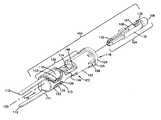
- FIG. 2shows a schematic view of a cross-connect arrangement of the type used for co-axial applications in combination with a diagrammatic view showing the face of a panel including connectors, pin jacks used to interconnect tracer lamp circuits of the cross-connect arrangement, and press-in place tracer lamp housings having features that are examples of inventive aspects in accordance with the present disclosure;
- FIG. 3shows a more detailed view of the face of one of the cross-connect panels including the connectors, the pin jack used to interconnect the tracer lamp circuit, and the press-in place tracer lamp housing;
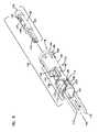
- FIG. 4shows an embodiment of the tracer lamp unit depicted in FIG. 3 in a disassembled configuration and in isolation from the cross-connect panel;
- FIG. 4Ashows a schematic view of a lighting arrangement of the type used with the tracer lamp unit of FIG. 4 ;
- FIG. 5shows the embodiment of the tracer lamp unit of FIG. 4 with only the LED flashing module removed from the housing;
- FIG. 6shows a front-end view of the embodiment of the tracer lamp unit of FIGS. 4 and 5 in an assembled configuration
- FIG. 7shows a top view of the embodiment of the tracer lamp unit of FIGS. 4–6 in an assembled configuration
- FIG. 8shows a left side view of the embodiment of the tracer lamp unit of FIGS. 4–7 in an assembled configuration
- FIG. 9shows a bottom view of the embodiment of the tracer lamp unit of FIGS. 4–8 in an assembled configuration
- FIG. 10shows a right side view of the embodiment of the tracer lamp unit of FIGS. 4–9 in an assembled configuration
- FIG. 10Ashows an enlarged fragmentary view of the embodiment of the tracer lamp unit of FIGS. 4–10 , with portions removed to show the contact between the leads of the lighting arrangement and the contact portions of the springs;
- FIG. 11shows a back-end view of the embodiment of the tracer lamp unit of FIGS. 4–10 in an assembled configuration.
- FIG. 2schematically illustrates an example of a cross-connect system of the type in which tracer lamp units 100 may be used.
- the tracer lamp units 100have features that are examples of inventive aspects in accordance with the principles of the present disclosure.
- the circuitry for linking the tracer lamp units 100 to the cross-connect systemis also shown diagrammatically.
- the tracer lamp units 100are illustrated in FIG. 2 as having been secured into openings defined by panels 60 that are part of the cross-connect system.
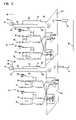
- FIG. 2schematically shows two DSX jack modules 20 and 22 wherein each of the jack modules 20 and 22 includes a tracer lamp circuit including switch 46 , LED tracer lamp unit 100 , pin jack unit 48 including conductors 49 , and wires electrically interconnecting the components.
- the wires electrically interconnecting the componentsinclude wires 58 connecting pin jack units 48 to the switches 46 , wires 52 connecting LED tracer lamp units 100 to power sources 42 , wires 54 connecting the switches 46 to the LED tracer lamp units 100 , and wires 56 connecting the switches 46 to the grounds 44 .
- wires 52 , 54 , 56 and 58can be terminated to their respective components by conventional techniques such as wire wrap connections, soldering, crimping or via terminals.
- the switches 46which have been illustrated schematically in FIG. 2 , can be configured to be closed manually after pin jacks of two jack modules have been connected to determine the cross-connectivity of the jack modules or can be incorporated into the cross connect system in such a way that they are automatically closed when plugs are inserted into selected ones of the ports (e.g., monitor-ports 38 ), thereby illuminating the tracer lamp units 100 .
- FIG. 3is a perspective view of a portion of one of the panels 60 schematically depicted in FIG. 2 .
- connectorscollectively referred to with reference number 150
- the pin jack unit 48 including conductor 49and the tracer lamp unit 100 are shown mounted in the panel 60 .
- FIGS. 4–11illustrate a tracer lamp unit 100 in isolation from the remainder of the cross-connect system of FIG. 2 .
- the tracer lamp unit 100includes a housing 102 having a securement structure (e.g., shear ribs 128 ) for coupling the tracer lamp unit to a piece of telecommunications equipment such as a panel or a jack module.
- the tracer lamp unit 100also includes a lighting arrangement 104 that mounts and is supported within the housing 102 .
- the lighting arrangementmay include arrangements such as an LED flashing arrangement or other arrangements.
- the lighting arrangement 104includes a lens 106 (e.g., any form of a lighting element that illuminates such as an LED, a bulb, etc.), a capacitor 107 , a resistor 108 , top and bottom leads 110 , and flashing control circuitry including integrated circuit (IC) 109 or other means for controlling flashing of lens 106 .
- the lighting arrangement 104is shown schematically in FIG. 4A .
- Flashing circuitryis optional and can have a variety of configurations.
- an integrated circuitmay include two timers on a monolithic chip. Alternatively, two separate timers could be used. One of the timers could operate in the a stable mode causing the LED to flash and the other timer could operate in a monostable mode causing the flashing to cease after a predetermined interval, with the LED remaining on.
- the capacitor 107 and the resistor 108may together determine the flashing rate of the LED.
- the resistor 108may determine the off-to-on ratio of the flashing cycle.
- the resistor 108 and the capacitor 107may together determine the interval after which flashing ceases. By these two separate means, the flashing interval and the rate of flashing of the LED may be independently set. Examples of LED flashing control circuitry may be found in U.S. Pat. Nos. 4,840,568 and 4,618,194, the entire disclosures of which are incorporated herein by reference.
- the tracer lamp unit housing 102includes a first end 118 (e.g., a front end), a second end 116 (e.g., a back end), a longitudinal axis passing therethrough represented by the dashed line 120 , a first side 117 (e.g., a right side), and a second side 119 (e.g., a left side).
- the housing 102also includes an outer surface 122 adapted to contact the piece of telecommunications equipment when inserted within the opening defined by the telecommunications equipment.
- the tracer lamp unit housing 102is configured to provide support for spring members 111 (e.g., FLED contact springs).
- the springs 111include electrical contact portions 114 and tail portions 112 (e.g., wire-wrap tails) and stabilization/mounting portions 113 positioned between the contact portions 114 to the tail portions 112 .
- the mounting portions 113are adapted to be press-fit into notches 129 of the housing 102 , the mounting portions 113 providing stability for the springs 111 when coupled to the housing 102 .
- the mounting portions 113 and the notches 129may include intermating structure such as snap-fit components (e.g., ramps, teeth, and etc.) for securing the springs within the housing 102 .
- the contact portions 114are configured to fit within contact openings 127 of the housing 102 .
- the contact portions 114include tabs 149 projecting sideways from the contact portions.
- the tabs 149rest on flat shoulders 148 of the housing 102 defined on the sides of the contact openings 127 of the housing.
- the tail portions 112project rearwardly from the second end 116 of the housing 102 in a longitudinal direction.
- the contact portions 114are adapted to contact the leads 110 of the lighting arrangement 104 , as shown in FIG. 10A , and establish a connection between the leads 110 of the lighting arrangement 104 and the tail portions 112 of the springs 111 .
- Tail portions 112can be connected to the cross-connect system by conventional techniques such as wire-wrap, solder, connectors or other techniques.
- the tracer lamp unit housing 102is made of a dielectric material such as molded plastic (e.g., polycarbonate), and is molded as a single, unitary piece.
- the housing 102is shown in FIGS. 4–11 as having an elongate configuration including a generally rounded cross section.
- “rounded”refers to any shape that is generally curvate including cylindrical, elliptical, oval, and etc.
- the housing 102includes a flange 124 that projects radially outwardly from the outer surface 122 at the first end 118 to ensure proper depth of insertion for the housing 102 .
- the flange 124has a rounded cross section, but may have a cross-section of any shape (e.g., rectangular, square, triangular, and etc.)
- the flange 124includes a back face 126 , adapted to abut against the piece of telecommunications equipment when the housing 102 is inserted within the opening defined by the telecommunications equipment, and a front face 138 , parallel to face 126 .
- the flange 124preferably, has a cross-dimension (e.g., diameter) less than 0.5 inches. More preferably, the flange 124 has a cross-dimension (e.g., diameter) less than 0.4 inches. Most preferably the flange 124 has a cross-dimension (e.g., diameter) of about 0.3 inches. In an embodiment wherein the flange 124 has a cross-dimension of about 0.3 inches, the opening defined by the telecommunications equipment, preferably, has a cross-dimension (e.g., diameter) of about 0.25 inches. Of course, in certain embodiments, the size may vary from those specifically referenced above.
- the housing 102also includes securement structures for coupling the tracer lamp unit 100 to the piece of telecommunications equipment.
- the securement structureis illustrated as a plurality of shear ribs 128 adjacent the flange 124 .
- the plurality of ribs 128are tapered so as to define an outer dimension 139 that increases in size in a direction extending from the second end 116 to the first end 118 .
- the shear ribs 128are sized accordingly to provide a press-in fit to the piece of telecommunications equipment.
- the shear ribs 128represent one example of many types of mounting structures that may be used for press fitting the housing 102 into an opening defined by the telecommunications equipment. Other structures such as bumps, tabs, ramps, ratchet teeth, shoulders, and etc. can be used to press-fit the housing 102 to the piece of telecommunications equipment.
- press-in fitrefers to any type of secure fit that can be generated by linearly inserting or pressing the housing 102 into a corresponding receptacle. Therefore, as used herein, the term press-fit or press-in fit includes snap-fit, friction fit, interference fit, taper-fit and etc.
- the housingalso includes a main body portion 130 extending from the plurality of shear ribs 128 to the second end 116 .
- the main body portion 130generally is adapted to provide structural support for components for establishing an electrical connection to a lighting arrangement 104 .
- the main body portion 130has a rounded cross section, but may have a cross-section of any shape (e.g., rectangular, square, triangular, and etc.).
- the main body portion 130 of the housing 102preferably, has a cross-dimension (e.g., diameter) less than 0.4 inches. More preferably, the main body portion 130 of the housing 102 has a cross-dimension (e.g., diameter) less than 0.3 inches.
- the main body portion 130 of the housing 102has a cross-dimension (e.g., diameter) of about 0.24 inches.
- the opening defined by the telecommunications equipmentpreferably, has a cross-dimension (e.g., diameter) of about 0.25 inches to enable the housing to be slidably inserted into the opening defined by the telecommunications opening.
- the sizemay vary from those specifically referenced above.
- the main body portion 130 of the housing 102includes certain structures having complementary shape to springs 111 to hold the springs 111 in a stable position relative to the housing 102 .
- the main body portion 130 of the housing 102also includes, adjacent the second end 116 , flex portions 133 defining the notches 129 shaped to receive the mounting/stabilization portions 113 of the springs 111 .
- the notches 129are generally U-shaped notches adapted to complement the shape of the springs 111 and slidably receive the mounting portions 113 of the springs 111 .
- the flex portions 133firmly hold the mounting portions 113 of the springs 111 with a press-in fit when the mounting portions 113 are inserted into the notches 129 .
- the flex portions 133 of the main-body portion 130 of the housingare adapted to flex radially outwardly when the mounting portions 113 of the springs 111 are slidably inserted into the notches 129 of the housing 102 .
- the mounting portions 113 of the springs 111may include ramps or other structures such as bumps, tabs, ratchet teeth, shoulders, and etc.
- the notches 129may include snap-fit slots defined by the flex portions 133 adapted to receive ramps of the mounting portions 113 of the springs 111 .
- the mounting portions 113 of the springs 111are slidably inserted into the notches 129 from the right side 117 of the housing 102 .
- openings for the notches 129can be located on the left side 119 of the housing.
- the notches 129can be configured such that springs 111 are inserted into the notches from both sides of the housing, one spring being inserted from the right side 117 , one spring being inserted from the left side 119 .
- the tail portions 112extend axially outwardly from the second end 116 .
- the tail portions 112are shaped to remain within the outer perimeter of the cross-section of the main body portion 130 such that no part of the springs 111 project outwardly radially beyond the curved boundary defined by the outer surface 122 of the housing at the main body portion 130 .
- the contact portions 114 of the springs 111are located inside the opening 127 of the main body portion 130 of the housing 102 when the mounting portions 113 of the springs 111 are inserted into the notches 129 , ready to engage the leads 110 .
- the main body portion 130defines flat shoulders 148 located on the sides of the opening 127 .
- the tabs 149 of the contact portions 114 of the springs 111rest on these flat shoulders 148 to prevent the contact portions 114 from touching each other when the lighting arrangement is not inserted into the housing 102 .
- the lighting arrangement 104may be part of a single module 132 removable from the housing 102 .
- the housing 102is adapted to slidably receive, provide structural support for, and be separable from the lighting module 132 .
- the lighting module 132is inserted into a single port 160 , the opening for which, is defined by the front face 138 of the housing (as shown in FIG. 6 ) to establish an electrical connection between the flashing control circuitry and the tail portions 112 of the springs 111 .
- the lighting module 132is held within the port 160 of the housing 102 due to a press-fit created between the contact portions 114 of the springs 111 and the leads 110 of the lighting arrangement 104 , as shown in FIG. 10A .
- the flashing control circuitryelectrically and mechanically disconnected from the tail portions 112 , and in turn, from the entire cross-connect system.
- the housingmay include an orientation feature 134 defined by the front face 138 to correctly orient the lighting module 132 before inserting it into the housing to ensure that a proper electrical connection has been established between the flashing control circuitry and the tail portions 112 of the tracer lamp unit 100 .
- the orientation feature 134includes a flat provided at one side of the otherwise round port 160 .
- the lighting module 132is shaped to complement the orientation feature 134 to provide for correct positioning of the module during insertion into the tracer lamp unit housing 102 .
- the module 132can have a complementary flat 135 .
- the tracer lamp unit housing 102is sized and shaped to be mounted in a D-shaped opening 200 defined at the front face of the panel 60 .
- the tracer lamp unit housing 102is mounted in the opening 200 by inserting the second end 116 of the tracer lamp unit housing 102 rearwardly through the opening 200 .
- the shear ribs 128make contact and start to press-against the surrounding edge 210 of the opening defined by the front face of the panel 60 until a press-fit connection with the panel 60 is established.
- the shear ribs 128are configured to securely retain the housing 102 within the opening 200 .
- the opening 200 defined by the telecommunications equipmentmay include an orientation feature 220 , illustrated as a flat positioned within an otherwise round hole, to correctly orient the tracer lamp unit housing 102 before inserting it into the telecommunications equipment.
- the housing 102is shaped to complement the orientation feature 220 to provide for correct positioning of the housing 102 during insertion into the panel 60 .
- the main body 130 of the housingincludes a flat 159 that complements the flat 220 of the hole 200 .
- the face 126 of the flange 124abuts against the panel 60 and ensures proper depth of insertion of the tracer lamp unit housing 102 into the panel 60 .
- the housing 102can simply be slid out of the opening 200 defined by the front face of the panel 60 using enough force to overcome the opposing frictional force provided by the interference fit between the shear ribs 128 and the edge 210 surrounding the opening 200 . If other types of structures such as bumps, tabs, ramps, ratchet teeth, shoulders, or etc. are used to press-fit the housing 102 to a piece of telecommunications equipment, the housing 102 can be uncoupled in various ways depending on the press-fit configuration used.
- the lighting arrangement 104is housed in a module 132 which is removable from the housing 102
- the lighting module 132can simply be removed from the housing 102 for replacement purposes without dislodging the housing 102 from the panel 60 .
Landscapes
- Engineering & Computer Science (AREA)
- Computer Networks & Wireless Communication (AREA)
- Arrangement Of Elements, Cooling, Sealing, Or The Like Of Lighting Devices (AREA)
Abstract
Description
Claims (18)
Priority Applications (4)
| Application Number | Priority Date | Filing Date | Title |
|---|---|---|---|
| US10/879,893US7182502B2 (en) | 2004-06-21 | 2004-06-21 | Press-in place LED for a digital switching cross-connect module |
| CN2005800279165ACN101006735B (en) | 2004-06-21 | 2005-06-17 | Press-in placed LED for a digital switching cross-connect module |
| PCT/US2005/021832WO2006002110A1 (en) | 2004-06-21 | 2005-06-17 | Press-in placed led for a digital switching cross-connect module |
| US11/703,051US7553063B2 (en) | 2004-06-21 | 2007-02-05 | Press-in place LED for a digital switching cross-connect module |
Applications Claiming Priority (1)
| Application Number | Priority Date | Filing Date | Title |
|---|---|---|---|
| US10/879,893US7182502B2 (en) | 2004-06-21 | 2004-06-21 | Press-in place LED for a digital switching cross-connect module |
Related Child Applications (1)
| Application Number | Title | Priority Date | Filing Date |
|---|---|---|---|
| US11/703,051ContinuationUS7553063B2 (en) | 2004-06-21 | 2007-02-05 | Press-in place LED for a digital switching cross-connect module |
Publications (2)
| Publication Number | Publication Date |
|---|---|
| US20050281032A1 US20050281032A1 (en) | 2005-12-22 |
| US7182502B2true US7182502B2 (en) | 2007-02-27 |
Family
ID=35160075
Family Applications (2)
| Application Number | Title | Priority Date | Filing Date |
|---|---|---|---|
| US10/879,893Expired - Fee RelatedUS7182502B2 (en) | 2004-06-21 | 2004-06-21 | Press-in place LED for a digital switching cross-connect module |
| US11/703,051Expired - LifetimeUS7553063B2 (en) | 2004-06-21 | 2007-02-05 | Press-in place LED for a digital switching cross-connect module |
Family Applications After (1)
| Application Number | Title | Priority Date | Filing Date |
|---|---|---|---|
| US11/703,051Expired - LifetimeUS7553063B2 (en) | 2004-06-21 | 2007-02-05 | Press-in place LED for a digital switching cross-connect module |
Country Status (3)
| Country | Link |
|---|---|
| US (2) | US7182502B2 (en) |
| CN (1) | CN101006735B (en) |
| WO (1) | WO2006002110A1 (en) |
Cited By (2)
| Publication number | Priority date | Publication date | Assignee | Title |
|---|---|---|---|---|
| US20070223254A1 (en)* | 2004-06-21 | 2007-09-27 | Adc Telecommunications, Inc. | Press-in place LED for a digital switching cross-connect module |
| US20100283372A1 (en)* | 2007-09-21 | 2010-11-11 | Koninklijke Philips Electronics N.V. | Lamp having contact members at its surrounding edge, and a lamp holder |
Families Citing this family (4)
| Publication number | Priority date | Publication date | Assignee | Title |
|---|---|---|---|---|
| AT11164U1 (en)* | 2008-10-15 | 2010-05-15 | Zumtobel Lighting Gmbh | LED INSTALLATION MODULE, LIGHTING ARRANGEMENT AND CEILING OR WALL CONSTRUCTION WITH THIS LED BUILT-IN MODULE |
| CN102059759B (en)* | 2010-10-26 | 2013-04-24 | 昆山华风风电科技有限公司 | Method for positioning shear ribs |
| WO2012060061A1 (en)* | 2010-11-04 | 2012-05-10 | パナソニック株式会社 | Bulb-type lamp and illuminating device |
| MX2012001219A (en) | 2012-01-27 | 2013-07-29 | Cemm Mex S A De C V | Module for a led lamp. |
Citations (43)
| Publication number | Priority date | Publication date | Assignee | Title |
|---|---|---|---|---|
| US1977105A (en)* | 1934-06-04 | 1934-10-16 | C D Wood Electric Company Inc | Lighting device |
| US3745510A (en)* | 1971-07-02 | 1973-07-10 | Interdyne Co | Printed circuit board/integrated circuit socket combination |
| US3794278A (en)* | 1972-01-10 | 1974-02-26 | Bourns Inc | Instrument supporting device |
| US3989343A (en) | 1976-01-27 | 1976-11-02 | Amp Incorporated | Means for mounting an electrical connector in a panel opening from either side of the panel |
| US4073563A (en) | 1974-11-05 | 1978-02-14 | Switchcraft, Inc. | Structure for electrical connections and panel assembly |
| US4618194A (en) | 1985-07-15 | 1986-10-21 | At&T Bell Laboratories | Connecting block for digital system cross-connect frame |
| US4687291A (en) | 1984-06-08 | 1987-08-18 | Amp Incorporated | Duplex electro-fiber connector assembly |
| US4720272A (en)* | 1985-07-03 | 1988-01-19 | Chrysler Motors Corporation | Snap-in terminal with wire guide |
| US4749968A (en) | 1985-12-13 | 1988-06-07 | Adc Telecommunications, Inc. | Jack device |
| US4768961A (en) | 1987-10-09 | 1988-09-06 | Switchcraft, Inc. | Jackfield with front removable jack modules having lamp assemblies |
| US4815104A (en) | 1988-01-11 | 1989-03-21 | Telect, Inc. | Digital telecommunications network, cross-connect module |
| US4840568A (en) | 1987-03-31 | 1989-06-20 | Adc Telecommunications, Inc. | Jack assembly |
| US5145416A (en) | 1989-12-19 | 1992-09-08 | Adc Telecommunications, Inc. | Jack assembly |
| US5147992A (en) | 1990-06-12 | 1992-09-15 | Adc Telecommunications, Inc. | Jack assembly |
| US5214673A (en) | 1989-08-04 | 1993-05-25 | Adc Telecommunications, Inc. | Digital cross connect assembly |
| US5233501A (en) | 1992-02-27 | 1993-08-03 | Telect, Inc. | Digital telecommunication network cross-connect module having a printed circuit board connected to jack switches |
| US5246378A (en) | 1989-08-09 | 1993-09-21 | Trimm, Inc. | Coaxial jack assembly |
| WO1993020600A1 (en) | 1992-04-02 | 1993-10-14 | Adc Telecommunications, Inc. | Miniature coax jack module |
| WO1994008429A1 (en) | 1992-10-05 | 1994-04-14 | Adc Telecommunications, Inc. | Jack module assembly |
| US5348491A (en) | 1993-10-29 | 1994-09-20 | Adc Telecommunications, Inc. | Jack module |
| US5366388A (en) | 1990-06-27 | 1994-11-22 | Digital Equipment Corporation | Wiring distribution system and devices for building wiring |
| US5393249A (en) | 1993-06-30 | 1995-02-28 | Adc Telecommunications, Inc. | Rear cross connect DSX system |
| US5513082A (en)* | 1994-12-16 | 1996-04-30 | Oshino Electric Lamp Works, Ltd. | Small lamp socket device for panel/printed board |
| US5538438A (en) | 1994-07-26 | 1996-07-23 | Ortronics, Inc. | RJ connector and cover therefor |
| US5577924A (en) | 1995-01-09 | 1996-11-26 | Adc Telecommunications, Inc. | Jack module with inductive monitor |
| WO1998038703A1 (en) | 1997-02-28 | 1998-09-03 | Adc Telecommunications, Inc. | Dsx module with removable jack |
| US5947771A (en) | 1996-04-02 | 1999-09-07 | Itt Manufacturing Enterprises, Inc. | Audio/power jack |
| US6019521A (en) | 1998-02-09 | 2000-02-01 | The Whitaker Corporation | Optical fiber connector |
| US6045378A (en) | 1998-03-27 | 2000-04-04 | Adc Telecommunications, Inc. | Switching coaxial jack with impedance matching |
| WO2000030219A2 (en) | 1998-11-12 | 2000-05-25 | Adc Telecommunications, Inc. | Jack assembly |
| US6132259A (en) | 1998-09-30 | 2000-10-17 | Lucent Technologies Inc. | Jacks formed by die casting |
| US6241562B1 (en) | 1999-06-22 | 2001-06-05 | Avaya Technology Corp. | Digital cross connect/interconnect module |
| US6287149B1 (en) | 1997-10-30 | 2001-09-11 | Thomas & Betts International, Inc. | Electrical connector having an improved connector shield and a multi-purpose strain relief |
| US6352444B1 (en) | 1997-09-30 | 2002-03-05 | The Whitaker Corporation | Coaxial connector, coaxial connector assembly and method of fabrication thereof |
| US6422902B1 (en) | 2000-11-10 | 2002-07-23 | Adc Telecommunications, Inc. | Low profile telecommunications jack with lamp switch |
| US6450829B1 (en) | 2000-12-15 | 2002-09-17 | Tyco Electronics Canada, Ltd. | Snap-on plug coaxial connector |
| US6503105B1 (en) | 2000-11-10 | 2003-01-07 | Adc Telecommunications, Inc. | Telecommunications jack subassembly |
| US6543626B1 (en) | 1999-05-21 | 2003-04-08 | Adc Telecommunications, Inc. | Cable management rack for telecommunication cross-connect systems |
| US6589062B1 (en) | 1999-04-06 | 2003-07-08 | Adc Telecommunications, Inc. | DSX module with removable jack |
| US6619993B2 (en) | 2001-06-01 | 2003-09-16 | Robert Jayne | DSX jack connection system |
| US6626705B2 (en) | 2001-07-13 | 2003-09-30 | Adc Telecommunications, Inc. | Jack module |
| US20040014365A1 (en) | 2002-07-19 | 2004-01-22 | Norris Jeffrey J. | Digital switching cross-connect module |
| US6743044B2 (en)* | 2002-08-14 | 2004-06-01 | Adc Telecommunications, Inc. | Cross-connect jumper assembly having tracer lamp |
Family Cites Families (3)
| Publication number | Priority date | Publication date | Assignee | Title |
|---|---|---|---|---|
| JPS6374581A (en)* | 1986-09-17 | 1988-04-05 | トキコ株式会社 | Electric robot |
| US5322501A (en)* | 1992-10-02 | 1994-06-21 | Mahmud Durrani Ayaz | Continent urethral stent for treating and preventing urethral stricture after surgery |
| US7182502B2 (en)* | 2004-06-21 | 2007-02-27 | Adc Telecommunications, Inc. | Press-in place LED for a digital switching cross-connect module |
- 2004
- 2004-06-21USUS10/879,893patent/US7182502B2/ennot_activeExpired - Fee Related
- 2005
- 2005-06-17CNCN2005800279165Apatent/CN101006735B/ennot_activeExpired - Fee Related
- 2005-06-17WOPCT/US2005/021832patent/WO2006002110A1/enactiveApplication Filing
- 2007
- 2007-02-05USUS11/703,051patent/US7553063B2/ennot_activeExpired - Lifetime
Patent Citations (50)
| Publication number | Priority date | Publication date | Assignee | Title |
|---|---|---|---|---|
| US1977105A (en)* | 1934-06-04 | 1934-10-16 | C D Wood Electric Company Inc | Lighting device |
| US3745510A (en)* | 1971-07-02 | 1973-07-10 | Interdyne Co | Printed circuit board/integrated circuit socket combination |
| US3794278A (en)* | 1972-01-10 | 1974-02-26 | Bourns Inc | Instrument supporting device |
| US4073563A (en) | 1974-11-05 | 1978-02-14 | Switchcraft, Inc. | Structure for electrical connections and panel assembly |
| US3989343A (en) | 1976-01-27 | 1976-11-02 | Amp Incorporated | Means for mounting an electrical connector in a panel opening from either side of the panel |
| US4687291A (en) | 1984-06-08 | 1987-08-18 | Amp Incorporated | Duplex electro-fiber connector assembly |
| US4720272A (en)* | 1985-07-03 | 1988-01-19 | Chrysler Motors Corporation | Snap-in terminal with wire guide |
| US4618194A (en) | 1985-07-15 | 1986-10-21 | At&T Bell Laboratories | Connecting block for digital system cross-connect frame |
| US4749968A (en) | 1985-12-13 | 1988-06-07 | Adc Telecommunications, Inc. | Jack device |
| US4840568A (en) | 1987-03-31 | 1989-06-20 | Adc Telecommunications, Inc. | Jack assembly |
| US4768961A (en) | 1987-10-09 | 1988-09-06 | Switchcraft, Inc. | Jackfield with front removable jack modules having lamp assemblies |
| US4815104A (en) | 1988-01-11 | 1989-03-21 | Telect, Inc. | Digital telecommunications network, cross-connect module |
| US4815104B1 (en) | 1988-01-11 | 1991-07-02 | Telect Inc | |
| US5214673A (en) | 1989-08-04 | 1993-05-25 | Adc Telecommunications, Inc. | Digital cross connect assembly |
| US5246378A (en) | 1989-08-09 | 1993-09-21 | Trimm, Inc. | Coaxial jack assembly |
| US5145416A (en) | 1989-12-19 | 1992-09-08 | Adc Telecommunications, Inc. | Jack assembly |
| US5147992A (en) | 1990-06-12 | 1992-09-15 | Adc Telecommunications, Inc. | Jack assembly |
| US5366388A (en) | 1990-06-27 | 1994-11-22 | Digital Equipment Corporation | Wiring distribution system and devices for building wiring |
| US5233501A (en) | 1992-02-27 | 1993-08-03 | Telect, Inc. | Digital telecommunication network cross-connect module having a printed circuit board connected to jack switches |
| WO1993020600A1 (en) | 1992-04-02 | 1993-10-14 | Adc Telecommunications, Inc. | Miniature coax jack module |
| US5467062A (en) | 1992-04-02 | 1995-11-14 | Adc Telecommunications, Inc. | Miniature coax jack module |
| US5413494A (en) | 1992-10-05 | 1995-05-09 | Adc Telecommunications, Inc. | Jack module assembly |
| WO1994008429A1 (en) | 1992-10-05 | 1994-04-14 | Adc Telecommunications, Inc. | Jack module assembly |
| US5393249A (en) | 1993-06-30 | 1995-02-28 | Adc Telecommunications, Inc. | Rear cross connect DSX system |
| US5348491A (en) | 1993-10-29 | 1994-09-20 | Adc Telecommunications, Inc. | Jack module |
| US5538438A (en) | 1994-07-26 | 1996-07-23 | Ortronics, Inc. | RJ connector and cover therefor |
| US5513082A (en)* | 1994-12-16 | 1996-04-30 | Oshino Electric Lamp Works, Ltd. | Small lamp socket device for panel/printed board |
| US5577924A (en) | 1995-01-09 | 1996-11-26 | Adc Telecommunications, Inc. | Jack module with inductive monitor |
| US5947771A (en) | 1996-04-02 | 1999-09-07 | Itt Manufacturing Enterprises, Inc. | Audio/power jack |
| US5913701A (en) | 1997-02-28 | 1999-06-22 | Adc Telecommunications, Inc. | DSX module with removable switching jack |
| WO1998038703A1 (en) | 1997-02-28 | 1998-09-03 | Adc Telecommunications, Inc. | Dsx module with removable jack |
| US6328608B1 (en) | 1997-02-28 | 2001-12-11 | Adc Telecommunications, Inc. | DSX module with removable jack |
| US6352444B1 (en) | 1997-09-30 | 2002-03-05 | The Whitaker Corporation | Coaxial connector, coaxial connector assembly and method of fabrication thereof |
| US6287149B1 (en) | 1997-10-30 | 2001-09-11 | Thomas & Betts International, Inc. | Electrical connector having an improved connector shield and a multi-purpose strain relief |
| US6019521A (en) | 1998-02-09 | 2000-02-01 | The Whitaker Corporation | Optical fiber connector |
| US6045378A (en) | 1998-03-27 | 2000-04-04 | Adc Telecommunications, Inc. | Switching coaxial jack with impedance matching |
| US6132259A (en) | 1998-09-30 | 2000-10-17 | Lucent Technologies Inc. | Jacks formed by die casting |
| WO2000030219A2 (en) | 1998-11-12 | 2000-05-25 | Adc Telecommunications, Inc. | Jack assembly |
| US6116961A (en) | 1998-11-12 | 2000-09-12 | Adc Telecommunications, Inc. | Jack assembly |
| US6589062B1 (en) | 1999-04-06 | 2003-07-08 | Adc Telecommunications, Inc. | DSX module with removable jack |
| US6543626B1 (en) | 1999-05-21 | 2003-04-08 | Adc Telecommunications, Inc. | Cable management rack for telecommunication cross-connect systems |
| US6241562B1 (en) | 1999-06-22 | 2001-06-05 | Avaya Technology Corp. | Digital cross connect/interconnect module |
| US6503105B1 (en) | 2000-11-10 | 2003-01-07 | Adc Telecommunications, Inc. | Telecommunications jack subassembly |
| US6422902B1 (en) | 2000-11-10 | 2002-07-23 | Adc Telecommunications, Inc. | Low profile telecommunications jack with lamp switch |
| US6450829B1 (en) | 2000-12-15 | 2002-09-17 | Tyco Electronics Canada, Ltd. | Snap-on plug coaxial connector |
| US6619993B2 (en) | 2001-06-01 | 2003-09-16 | Robert Jayne | DSX jack connection system |
| US6626705B2 (en) | 2001-07-13 | 2003-09-30 | Adc Telecommunications, Inc. | Jack module |
| US20040014365A1 (en) | 2002-07-19 | 2004-01-22 | Norris Jeffrey J. | Digital switching cross-connect module |
| US6830486B2 (en)* | 2002-07-19 | 2004-12-14 | Adc Telecommunications, Inc. | Digital switching cross-connect module |
| US6743044B2 (en)* | 2002-08-14 | 2004-06-01 | Adc Telecommunications, Inc. | Cross-connect jumper assembly having tracer lamp |
Non-Patent Citations (1)
| Title |
|---|
| Brochure, "Video Signal Distribution Products," ADC Telecommunications, 47 pages (Oct. 1996). |
Cited By (4)
| Publication number | Priority date | Publication date | Assignee | Title |
|---|---|---|---|---|
| US20070223254A1 (en)* | 2004-06-21 | 2007-09-27 | Adc Telecommunications, Inc. | Press-in place LED for a digital switching cross-connect module |
| US7553063B2 (en)* | 2004-06-21 | 2009-06-30 | Adc Telecommunications, Inc. | Press-in place LED for a digital switching cross-connect module |
| US20100283372A1 (en)* | 2007-09-21 | 2010-11-11 | Koninklijke Philips Electronics N.V. | Lamp having contact members at its surrounding edge, and a lamp holder |
| US8564182B2 (en) | 2007-09-21 | 2013-10-22 | Koninklijke Philips N.V. | Lamp having contact members at its surrounding edge, and a lamp holder |
Also Published As
| Publication number | Publication date |
|---|---|
| CN101006735B (en) | 2010-05-12 |
| US20070223254A1 (en) | 2007-09-27 |
| US20050281032A1 (en) | 2005-12-22 |
| US7553063B2 (en) | 2009-06-30 |
| CN101006735A (en) | 2007-07-25 |
| WO2006002110A1 (en) | 2006-01-05 |
Similar Documents
| Publication | Publication Date | Title |
|---|---|---|
| US6632106B2 (en) | Jack; jack assembly; and methods | |
| US7524211B2 (en) | Digital switching cross-connect module | |
| US6743044B2 (en) | Cross-connect jumper assembly having tracer lamp | |
| TWI241749B (en) | Front access DSX assembly | |
| US7815439B2 (en) | Insulation displacement plug-in connector and device for telecommunications and data technology | |
| US7553063B2 (en) | Press-in place LED for a digital switching cross-connect module | |
| US6626705B2 (en) | Jack module | |
| US4415214A (en) | Electrical plug and socket connectors | |
| CN101682799B (en) | DSX module with balun mounted on board | |
| CA2572768C (en) | Long frame high density patching system | |
| US11817642B2 (en) | Modular plug connector for a printed circuit board | |
| US6830487B2 (en) | Pin jack for a digital switching cross-connect module | |
| US5800218A (en) | S110 test adapter | |
| US7150656B1 (en) | Digital switching cross-connect module | |
| US6167617B1 (en) | Method of blind connecting an I/O module into a cabinet | |
| CN2410825Y (en) | Digital distribution module for telecommunication system | |
| KR20020095788A (en) | Structure of the multi-purpose terminal block |
Legal Events
| Date | Code | Title | Description |
|---|---|---|---|
| AS | Assignment | Owner name:ADC TELECOMMUNICATIONS, INC., MINNESOTA Free format text:ASSIGNMENT OF ASSIGNORS INTEREST;ASSIGNOR:PETERSEN, CYLE D.;REEL/FRAME:015995/0833 Effective date:20041008 | |
| STCF | Information on status: patent grant | Free format text:PATENTED CASE | |
| FPAY | Fee payment | Year of fee payment:4 | |
| FPAY | Fee payment | Year of fee payment:8 | |
| AS | Assignment | Owner name:TYCO ELECTRONICS SERVICES GMBH, SWITZERLAND Free format text:ASSIGNMENT OF ASSIGNORS INTEREST;ASSIGNOR:ADC TELECOMMUNICATIONS, INC.;REEL/FRAME:036060/0174 Effective date:20110930 | |
| AS | Assignment | Owner name:COMMSCOPE EMEA LIMITED, IRELAND Free format text:ASSIGNMENT OF ASSIGNORS INTEREST;ASSIGNOR:TYCO ELECTRONICS SERVICES GMBH;REEL/FRAME:036956/0001 Effective date:20150828 | |
| AS | Assignment | Owner name:COMMSCOPE TECHNOLOGIES LLC, NORTH CAROLINA Free format text:ASSIGNMENT OF ASSIGNORS INTEREST;ASSIGNOR:COMMSCOPE EMEA LIMITED;REEL/FRAME:037012/0001 Effective date:20150828 | |
| AS | Assignment | Owner name:JPMORGAN CHASE BANK, N.A., AS COLLATERAL AGENT, ILLINOIS Free format text:PATENT SECURITY AGREEMENT (TERM);ASSIGNOR:COMMSCOPE TECHNOLOGIES LLC;REEL/FRAME:037513/0709 Effective date:20151220 Owner name:JPMORGAN CHASE BANK, N.A., AS COLLATERAL AGENT, ILLINOIS Free format text:PATENT SECURITY AGREEMENT (ABL);ASSIGNOR:COMMSCOPE TECHNOLOGIES LLC;REEL/FRAME:037514/0196 Effective date:20151220 Owner name:JPMORGAN CHASE BANK, N.A., AS COLLATERAL AGENT, IL Free format text:PATENT SECURITY AGREEMENT (ABL);ASSIGNOR:COMMSCOPE TECHNOLOGIES LLC;REEL/FRAME:037514/0196 Effective date:20151220 Owner name:JPMORGAN CHASE BANK, N.A., AS COLLATERAL AGENT, IL Free format text:PATENT SECURITY AGREEMENT (TERM);ASSIGNOR:COMMSCOPE TECHNOLOGIES LLC;REEL/FRAME:037513/0709 Effective date:20151220 | |
| FEPP | Fee payment procedure | Free format text:MAINTENANCE FEE REMINDER MAILED (ORIGINAL EVENT CODE: REM.); ENTITY STATUS OF PATENT OWNER: LARGE ENTITY | |
| LAPS | Lapse for failure to pay maintenance fees | Free format text:PATENT EXPIRED FOR FAILURE TO PAY MAINTENANCE FEES (ORIGINAL EVENT CODE: EXP.); ENTITY STATUS OF PATENT OWNER: LARGE ENTITY | |
| STCH | Information on status: patent discontinuation | Free format text:PATENT EXPIRED DUE TO NONPAYMENT OF MAINTENANCE FEES UNDER 37 CFR 1.362 | |
| AS | Assignment | Owner name:ANDREW LLC, NORTH CAROLINA Free format text:RELEASE BY SECURED PARTY;ASSIGNOR:JPMORGAN CHASE BANK, N.A.;REEL/FRAME:048840/0001 Effective date:20190404 Owner name:REDWOOD SYSTEMS, INC., NORTH CAROLINA Free format text:RELEASE BY SECURED PARTY;ASSIGNOR:JPMORGAN CHASE BANK, N.A.;REEL/FRAME:048840/0001 Effective date:20190404 Owner name:COMMSCOPE, INC. OF NORTH CAROLINA, NORTH CAROLINA Free format text:RELEASE BY SECURED PARTY;ASSIGNOR:JPMORGAN CHASE BANK, N.A.;REEL/FRAME:048840/0001 Effective date:20190404 Owner name:COMMSCOPE TECHNOLOGIES LLC, NORTH CAROLINA Free format text:RELEASE BY SECURED PARTY;ASSIGNOR:JPMORGAN CHASE BANK, N.A.;REEL/FRAME:048840/0001 Effective date:20190404 Owner name:ALLEN TELECOM LLC, ILLINOIS Free format text:RELEASE BY SECURED PARTY;ASSIGNOR:JPMORGAN CHASE BANK, N.A.;REEL/FRAME:048840/0001 Effective date:20190404 Owner name:COMMSCOPE TECHNOLOGIES LLC, NORTH CAROLINA Free format text:RELEASE BY SECURED PARTY;ASSIGNOR:JPMORGAN CHASE BANK, N.A.;REEL/FRAME:049260/0001 Effective date:20190404 Owner name:ANDREW LLC, NORTH CAROLINA Free format text:RELEASE BY SECURED PARTY;ASSIGNOR:JPMORGAN CHASE BANK, N.A.;REEL/FRAME:049260/0001 Effective date:20190404 Owner name:REDWOOD SYSTEMS, INC., NORTH CAROLINA Free format text:RELEASE BY SECURED PARTY;ASSIGNOR:JPMORGAN CHASE BANK, N.A.;REEL/FRAME:049260/0001 Effective date:20190404 Owner name:COMMSCOPE, INC. OF NORTH CAROLINA, NORTH CAROLINA Free format text:RELEASE BY SECURED PARTY;ASSIGNOR:JPMORGAN CHASE BANK, N.A.;REEL/FRAME:049260/0001 Effective date:20190404 Owner name:ALLEN TELECOM LLC, ILLINOIS Free format text:RELEASE BY SECURED PARTY;ASSIGNOR:JPMORGAN CHASE BANK, N.A.;REEL/FRAME:049260/0001 Effective date:20190404 | |
| FP | Lapsed due to failure to pay maintenance fee | Effective date:20190227 | |
| AS | Assignment | Owner name:JPMORGAN CHASE BANK, N.A., NEW YORK Free format text:TERM LOAN SECURITY AGREEMENT;ASSIGNORS:COMMSCOPE, INC. OF NORTH CAROLINA;COMMSCOPE TECHNOLOGIES LLC;ARRIS ENTERPRISES LLC;AND OTHERS;REEL/FRAME:049905/0504 Effective date:20190404 Owner name:JPMORGAN CHASE BANK, N.A., NEW YORK Free format text:ABL SECURITY AGREEMENT;ASSIGNORS:COMMSCOPE, INC. OF NORTH CAROLINA;COMMSCOPE TECHNOLOGIES LLC;ARRIS ENTERPRISES LLC;AND OTHERS;REEL/FRAME:049892/0396 Effective date:20190404 Owner name:WILMINGTON TRUST, NATIONAL ASSOCIATION, AS COLLATE Free format text:PATENT SECURITY AGREEMENT;ASSIGNOR:COMMSCOPE TECHNOLOGIES LLC;REEL/FRAME:049892/0051 Effective date:20190404 Owner name:WILMINGTON TRUST, NATIONAL ASSOCIATION, AS COLLATERAL AGENT, CONNECTICUT Free format text:PATENT SECURITY AGREEMENT;ASSIGNOR:COMMSCOPE TECHNOLOGIES LLC;REEL/FRAME:049892/0051 Effective date:20190404 | |
| AS | Assignment | Owner name:RUCKUS WIRELESS, LLC (F/K/A RUCKUS WIRELESS, INC.), NORTH CAROLINA Free format text:RELEASE OF SECURITY INTEREST AT REEL/FRAME 049905/0504;ASSIGNOR:JPMORGAN CHASE BANK, N.A., AS COLLATERAL AGENT;REEL/FRAME:071477/0255 Effective date:20241217 Owner name:COMMSCOPE TECHNOLOGIES LLC, NORTH CAROLINA Free format text:RELEASE OF SECURITY INTEREST AT REEL/FRAME 049905/0504;ASSIGNOR:JPMORGAN CHASE BANK, N.A., AS COLLATERAL AGENT;REEL/FRAME:071477/0255 Effective date:20241217 Owner name:COMMSCOPE, INC. OF NORTH CAROLINA, NORTH CAROLINA Free format text:RELEASE OF SECURITY INTEREST AT REEL/FRAME 049905/0504;ASSIGNOR:JPMORGAN CHASE BANK, N.A., AS COLLATERAL AGENT;REEL/FRAME:071477/0255 Effective date:20241217 Owner name:ARRIS SOLUTIONS, INC., NORTH CAROLINA Free format text:RELEASE OF SECURITY INTEREST AT REEL/FRAME 049905/0504;ASSIGNOR:JPMORGAN CHASE BANK, N.A., AS COLLATERAL AGENT;REEL/FRAME:071477/0255 Effective date:20241217 Owner name:ARRIS TECHNOLOGY, INC., NORTH CAROLINA Free format text:RELEASE OF SECURITY INTEREST AT REEL/FRAME 049905/0504;ASSIGNOR:JPMORGAN CHASE BANK, N.A., AS COLLATERAL AGENT;REEL/FRAME:071477/0255 Effective date:20241217 Owner name:ARRIS ENTERPRISES LLC (F/K/A ARRIS ENTERPRISES, INC.), NORTH CAROLINA Free format text:RELEASE OF SECURITY INTEREST AT REEL/FRAME 049905/0504;ASSIGNOR:JPMORGAN CHASE BANK, N.A., AS COLLATERAL AGENT;REEL/FRAME:071477/0255 Effective date:20241217 |