US7182422B2 - Printhead having first and second rows of print nozzles - Google Patents
Printhead having first and second rows of print nozzlesDownload PDFInfo
- Publication number
- US7182422B2 US7182422B2US10/922,845US92284504AUS7182422B2US 7182422 B2US7182422 B2US 7182422B2US 92284504 AUS92284504 AUS 92284504AUS 7182422 B2US7182422 B2US 7182422B2
- Authority
- US
- United States
- Prior art keywords
- rows
- circuitry
- row
- nozzles
- module according
- Prior art date
- Legal status (The legal status is an assumption and is not a legal conclusion. Google has not performed a legal analysis and makes no representation as to the accuracy of the status listed.)
- Expired - Lifetime, expires
Links
Images


Classifications
- B—PERFORMING OPERATIONS; TRANSPORTING
- B41—PRINTING; LINING MACHINES; TYPEWRITERS; STAMPS
- B41J—TYPEWRITERS; SELECTIVE PRINTING MECHANISMS, i.e. MECHANISMS PRINTING OTHERWISE THAN FROM A FORME; CORRECTION OF TYPOGRAPHICAL ERRORS
- B41J2/00—Typewriters or selective printing mechanisms characterised by the printing or marking process for which they are designed
- B41J2/005—Typewriters or selective printing mechanisms characterised by the printing or marking process for which they are designed characterised by bringing liquid or particles selectively into contact with a printing material
- B41J2/01—Ink jet
- B41J2/135—Nozzles
- B41J2/14—Structure thereof only for on-demand ink jet heads
- B—PERFORMING OPERATIONS; TRANSPORTING
- B41—PRINTING; LINING MACHINES; TYPEWRITERS; STAMPS
- B41J—TYPEWRITERS; SELECTIVE PRINTING MECHANISMS, i.e. MECHANISMS PRINTING OTHERWISE THAN FROM A FORME; CORRECTION OF TYPOGRAPHICAL ERRORS
- B41J2/00—Typewriters or selective printing mechanisms characterised by the printing or marking process for which they are designed
- B41J2/005—Typewriters or selective printing mechanisms characterised by the printing or marking process for which they are designed characterised by bringing liquid or particles selectively into contact with a printing material
- B41J2/01—Ink jet
- B41J2/135—Nozzles
- B41J2/145—Arrangement thereof
- B41J2/155—Arrangement thereof for line printing
- B—PERFORMING OPERATIONS; TRANSPORTING
- B41—PRINTING; LINING MACHINES; TYPEWRITERS; STAMPS
- B41J—TYPEWRITERS; SELECTIVE PRINTING MECHANISMS, i.e. MECHANISMS PRINTING OTHERWISE THAN FROM A FORME; CORRECTION OF TYPOGRAPHICAL ERRORS
- B41J2/00—Typewriters or selective printing mechanisms characterised by the printing or marking process for which they are designed
- B41J2/005—Typewriters or selective printing mechanisms characterised by the printing or marking process for which they are designed characterised by bringing liquid or particles selectively into contact with a printing material
- B41J2/01—Ink jet
- B41J2/135—Nozzles
- B41J2/14—Structure thereof only for on-demand ink jet heads
- B41J2002/14491—Electrical connection
Definitions
- the present inventionrelates to the field of printheads.
- the inventionhas primarily been developed for use with applicant's inkjet printhead comprising a plurality of printhead modules extending across a pagewidth, and will be described with reference to this application. However, it will be appreciated that the invention can be applied to other printhead arrangements having multiple rows of print nozzles.
- One of theserelates to the provision of drive and control signals to nozzles.
- One way to do thisis to have a CMOS layer in the same substrate as the print nozzles are constructed. This integration saves space and enables relatively short links between drive circuitry and nozzle actuators.
- each color in a printheadincludes an odd and an even row, which are offset across the pagewidth by half the horizontal nozzle pitch.
- Each nozzle and its drive circuitare arranged, in plan, in a line parallel to the direction of print media travel relative to the printhead.
- all the nozzle/circuitry pairs in printheadare orientated in the same way. Using odd and even rows offset by half the horizontal nozzle pitch allows dots to be printed more closely together across the page than would be possible if the nozzles and associated drive circuitry had to be positioned side by side in a single row. Dot data to the appropriate row needs to be delayed such that data printed by the two rows ends up aligned correctly on the page.
- the relative difference in space requirement for the CMOS and nozzlesmeans there is still some wasted area in the printhead. Also, in designs where high-voltage circuitry is disposed adjacent low-voltage circuitry from another row, careful design and spacing is required to avoid interference between the two.
- the present inventionprovides a printhead module comprising at least first and second rows of print nozzles that extend along at least part of a pagewidth to be printed, each nozzle including first circuitry of a first type and second circuitry of a second type, such that, in plan view, the first and second circuitry are generally located at opposite ends of the nozzle, wherein the nozzles are orientated such that the respective positions of the first and second circuitry of each nozzle of the first row are mirrored or rotated relative to the respective positions of the first and second circuitry of corresponding nozzles in the second row.
- the respective positions of the first and second circuitry of each nozzle of the first roware rotated 180 degrees relative to the respective positions of the first and second circuitry of the corresponding nozzles in the second row.
- first and second circuitry of each nozzleare positioned in a line perpendicular to the pagewidth.
- the first and second rows of nozzlesat least partially interlock.
- the first circuitry of each nozzle in the first rowat least partially interlocks with the first circuitry of at least one adjacent nozzle from the second row.
- each of at least a majority of nozzles in the first rowis paired with a corresponding nozzle in the second row.
- the printhead moduleincludes a plurality of first rows and second rows, each of the first rows being paired with one of the second rows.
- the first and second rowsare configured to print the same color.
- the first and second rowsare configured to print the same ink.
- the first and second rowsare coupled to the same ink supply.
- the printheadfurther includes a plurality of first rows and second rows, each of the first rows being paired with one of the second rows, wherein the first and second rows in each pair are configured to print the same ink as each other.
- first and second rows in each pairare coupled to the same ink supply.
- the first and second rowsare configured to share at least one power supply node.
- the power supply nodeis an earth.
- the earthis rated to conduct current on the basis that only one of the first and second rows will be conducting current to earth at any one time.
- the power supply nodeis a current supply conduit.
- the current supply conduitis rated to conduct current on the basis that only one of the first and second rows will be sourcing current via the current supply conduit at any one time.
- the first and second rowsare configured to share at least one global signal.
- the global signalis a fire signal.
- the global signalis a clock signal.
- the present inventionprovides a printhead module comprising at least first and second rows of print nozzles that extend along at least part of a pagewidth to be printed, each nozzle including first circuitry of a first type and second circuitry of a second type, such that, in plan view, the first and second circuitry are generally located at opposite ends of the nozzle, wherein the nozzles are orientated such that the first circuitry of the nozzles of the first row are closer to the first circuitry of the nozzles of the second row than to the second circuitry of the nozzles of the second row.
- the respective positions of the first and second circuitry of each nozzle of the first roware rotated 180 degrees relative to the respective positions of the first and second circuitry of the corresponding nozzles in the second row.
- first and second circuitry of each nozzleare positioned in a line perpendicular to the pagewidth.
- first and second rows of nozzlesat least partially interlock.
- the first circuitry of each nozzle in the first rowat least partially interlocks with the first circuitry of at least one adjacent nozzle from the second row.
- each of at least a majority of nozzles in the first rowis paired with a corresponding nozzle in the second row.
- the printhead moduleincludes a plurality of first rows and second rows, each of the first rows being paired with one of the second rows.
- the first and second rowsare configured to print the same color.
- the first and second rowsare configured to print the same ink.
- the first and second rowsare coupled to the same ink supply.
- printheadincluding a plurality of first rows and second rows, each of the first rows being paired with one of the second rows, wherein the first and second rows in each pair are configured to print the same ink as each other.
- first and second rows in each pairare coupled to the same ink supply.
- the first and second rowsare configured to share at least one power supply node.
- the power supply nodeis an earth.
- the earthis rated to conduct current on the basis that only one of the first and second rows will be conducting current to earth at any one time.
- the power supply nodeis a current supply conduit.
- the current supply conduitis rated to conduct current on the basis that only one of the first and second rows will be sourcing current via the current supply conduit at any one time.
- the first and second rowsare configured to share at least one global signal.
- the global signalis a fire signal.
- the global signalis a clock signal.
- FIG. 1shows schematics of three separate layers that comprise a unit cell (ie, a nozzle) of a printhead;
- FIG. 2shows a vertical elevation of the three layers of FIG. 1 , in their operative relative positions
- FIG. 3shows a known layout of columns and rows of the unit cells of FIGS. 1 and 2 ;
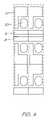
- FIG. 4shows a layout of columns and rows of the unit cells of FIGS. 1 and 2 , in accordance with the invention.
- FIG. 1shows the three layers 2 , 4 , 6 that together make up a unit cell 1 (ie, a nozzle) 1 for a MemjetTM MEMS printhead.
- a unit cell 1ie, a nozzle
- FIG. 1shows three separate layers in plan, it will be appreciated that, in use, the unit cell is manufactured such that the layers are stacked on top of each other, as shown in side elevation in FIG. 2 .
- each of the layers 2 , 4 , 6is made up of further sublayers and subcomponents, the details of which are omitted for clarity.
- the lowest layer 2contains active CMOS circuits, and is divided into two main regions.
- the first regioncontains low voltage CMOS logic circuits 8 that control whether and when the cell 1 ejects ink.
- the second regioncontains high voltage CMOS, comprising a large drive transistor 10 that provides the electric current to an actuator (see FIG. 2 ) that ejects the ink when enabled by the control logic.
- the intermediate layer 4is made up of CMOS metal layer structures that provide contacts to the MEMs layer 6 .
- the drive transistor 10connects to a drive contact area 12 .
- a ground contact area 14provides a return path for the current and lies physically above the control logic region 8 .
- the upper layer 6is a MEMs layer that includes a MEMs actuator 17 .
- the actuator 17is connected at one end 16 to the drive transistor 10 through contact area 12 , and at the other end 18 to ground contact area 14 .
- the connection through the various layersis best shown in FIG. 2 .
- an ink hole 20extends through the first and second layers 2 , 4 to supply ink to the third layer 6 for expulsion by the actuator.
- CMOS active layerAs shown in FIG. 3 , when unit cells (ie, nozzles) 1 are arrayed in rows and columns to form a complete prior art printhead, various constraints apply to abutting cells. For clarity, only the CMOS active layer is shown but the position and orientation of the others layers will be clear to one skilled in the art based on the nozzle layout shown in FIG. 1
- control logic circuits 8 of horizontally adjacent rows of nozzles 1generally abut directly, and global control signals are routed through this area so that they are provided to each cell.
- the ground contact areas (not shown) of horizontally adjacent cellsform a continuous metal strip.
- the vertical spacing of the rowsis determined by the spacing constraints that apply to each layer.
- the critical spacingis between the high voltage area of one cell, and the low voltage area of the cell in the adjacent row.
- the critical spacingis between the drive contact of one cell, and the ground contact of the cell in the adjacent row.
- the critical spacingis between the drive terminal of one actuator, and the ground contact of the actuator in the adjacent row
- FIG. 4shows the preferred embodiment of arranging cells into rows in an array, in which every second row is flipped or mirrored.
- Reference numerals used in this Figurecorrespond with the features described earlier for those numerals.
- the relationship between high and low voltage regionsallows a smaller overall vertical row pitch for given unit cell component sizes.
- pairs of rowshave abutting control logic regions 8 . This allows global signals to be routed through the array once every row pair, rather than once every row. Additionally, each high voltage region directly abuts only other high voltage regions, halving the number of high-voltage to low-voltage separations in the array.
- pairs of rowscan share a common ground contact area. As cells in adjacent rows are never fired simultaneously in the preferred embodiment, this shared ground contact need only be large enough to carry the current for a single row. Similarly, the ground terminals of the actuators on the MEMs layer (see FIG. 1 ) can be shared, reducing the size requirement. Although not shown in this embodiment, current can also be supplied to the drive circuits by way of a supply current conduit shared by adjacent rows.
- alternate rows of nozzlesare rotated 180 degrees relative to each other, it will be appreciated that they can also be mirror images of each other. Moreover, the rotation or mirroring need not involve a complete 180 degree rotational offset. Much of the advantage of the invention can be achieved with lesser angles of relative rotation. Also, although the preferred embodiment shows devices that are identical in plan, it will be appreciated that the devices in the rows need not be identical. It need merely be the case that the requirement of at least some of the circuitry of nozzles in adjacent rows is asymmetric, such that space and/or design improvements can be taken advantage of by flipping, mirroring or otherwise rotating the nozzle layouts in adjacent rows.
- the present inventionoffers a smaller array size than existing layouts, without affecting the CMOS and MEMs component sizes.
Landscapes
- Particle Formation And Scattering Control In Inkjet Printers (AREA)
Abstract
Description
- Ser. No. 10/922,846
| 09/517,539 | 09/112,763 | 09/112,762 | 09/112,737 | 09/112,761 |
| 09/113,223 | 09/517,384 | 09/505,951 | 09/516,869 | 09/517,608 |
| 09/505,147 | 09/505,952 | 09/517,380 | 09/516,874 | 09/517,541 |
| 10/203,540 | 10/636,263 | 10/203,564 | 10/636,283 | 10/866,608 |
| 10/902,889 | 10/902,833 | 10/407,212 | 10/407,207 | 10/683,064 |
| 10/683,041 | 10/882,774 | 10/884,889 | 10/727,181 | 10/727,162 |
| 10/727,163 | 10/727,245 | 10/727,204 | 10/727,233 | 10/727,280 |
| 10/727,157 | 10/727,178 | 10/727,210 | 10/727,257 | 10/727,238 |
| 10/727,251 | 10/727,159 | 10/727,180 | 10/727,179 | 10/727,192 |
| 10/727,274 | 10/727,164 | 10/727,161 | 10/727,198 | 10/727,158 |
| 10/754,536 | 10/754,938 | 10/727,227 | 10/727,160 | 09/575,108 |
| 10/884,881 | 09/575,109 | 09/575,110 | 09/607,985 | 09/607,990 |
| 09/607,196 | 09/606,999 | 10/173,739 | 10/189,459 | 10/854,521 |
| 10/854,522 | 10/854,488 | 10/854,487 | 10/854,503 | 10/854,504 |
| 10/854,509 | 10/854,511 | 7,093,989 | 10/854,497 | 10/854,495 |
| 10/854,498 | 10/854,511 | 10/854,512 | 10/854,525 | 10/854,526 |
| 10/854,516 | 10/854,508 | 10/854,507 | 10/854,515 | 10/854,506 |
| 10/854,505 | 10/854,493 | 10/854,494 | 10/854,489 | 10/854,490 |
| 10/854,492 | 10/854,491 | 10/854,528 | 10/854,523 | 10/854,527 |
| 10/854,524 | 10/854,520 | 10/854,514 | 10/854,519 | 10/854,513 |
| 10/854,499 | 10/854,501 | 10/854,500 | 10/854,502 | 10/854,518 |
| 10/854,517 | ||||
Claims (19)
Priority Applications (4)
| Application Number | Priority Date | Filing Date | Title |
|---|---|---|---|
| US10/922,845US7182422B2 (en) | 2004-08-23 | 2004-08-23 | Printhead having first and second rows of print nozzles |
| US11/650,537US7866791B2 (en) | 2004-08-23 | 2007-01-08 | Printhead having mirrored rows of print nozzles |
| US12/972,512US8079663B2 (en) | 2004-08-23 | 2010-12-19 | Printhead having mirrored rows of print nozzles |
| US13/330,348US8382246B2 (en) | 2004-08-23 | 2011-12-19 | Printhead having mirrored rows of print nozzles |
Applications Claiming Priority (1)
| Application Number | Priority Date | Filing Date | Title |
|---|---|---|---|
| US10/922,845US7182422B2 (en) | 2004-08-23 | 2004-08-23 | Printhead having first and second rows of print nozzles |
Related Child Applications (1)
| Application Number | Title | Priority Date | Filing Date |
|---|---|---|---|
| US11/650,537ContinuationUS7866791B2 (en) | 2001-02-07 | 2007-01-08 | Printhead having mirrored rows of print nozzles |
Publications (2)
| Publication Number | Publication Date |
|---|---|
| US20060038849A1 US20060038849A1 (en) | 2006-02-23 |
| US7182422B2true US7182422B2 (en) | 2007-02-27 |
Family
ID=35909216
Family Applications (4)
| Application Number | Title | Priority Date | Filing Date |
|---|---|---|---|
| US10/922,845Expired - LifetimeUS7182422B2 (en) | 2004-08-23 | 2004-08-23 | Printhead having first and second rows of print nozzles |
| US11/650,537Active2027-06-28US7866791B2 (en) | 2001-02-07 | 2007-01-08 | Printhead having mirrored rows of print nozzles |
| US12/972,512Expired - Fee RelatedUS8079663B2 (en) | 2004-08-23 | 2010-12-19 | Printhead having mirrored rows of print nozzles |
| US13/330,348Expired - Fee RelatedUS8382246B2 (en) | 2004-08-23 | 2011-12-19 | Printhead having mirrored rows of print nozzles |
Family Applications After (3)
| Application Number | Title | Priority Date | Filing Date |
|---|---|---|---|
| US11/650,537Active2027-06-28US7866791B2 (en) | 2001-02-07 | 2007-01-08 | Printhead having mirrored rows of print nozzles |
| US12/972,512Expired - Fee RelatedUS8079663B2 (en) | 2004-08-23 | 2010-12-19 | Printhead having mirrored rows of print nozzles |
| US13/330,348Expired - Fee RelatedUS8382246B2 (en) | 2004-08-23 | 2011-12-19 | Printhead having mirrored rows of print nozzles |
Country Status (1)
| Country | Link |
|---|---|
| US (4) | US7182422B2 (en) |
Cited By (2)
| Publication number | Priority date | Publication date | Assignee | Title |
|---|---|---|---|---|
| US20070153039A1 (en)* | 2004-08-23 | 2007-07-05 | Silverbrook Research Pty Ltd | Printhead having rows of symmetrically arranged nozzles |
| US20110085006A1 (en)* | 2004-08-23 | 2011-04-14 | Silverbrook Research Pty Ltd | Printhead having Mirrored Rows of Print Nozzles |
Families Citing this family (5)
| Publication number | Priority date | Publication date | Assignee | Title |
|---|---|---|---|---|
| US8128205B2 (en) | 2005-10-31 | 2012-03-06 | Hewlett-Packard Development Company, L.P. | Fluid ejection device |
| US11642884B2 (en)* | 2019-02-06 | 2023-05-09 | Hewlett-Packard Development Company, L.P. | Die for a printhead |
| ES2985221T3 (en) | 2019-02-06 | 2024-11-04 | Hewlett Packard Development Co | Die for a print head |
| WO2020162912A1 (en) | 2019-02-06 | 2020-08-13 | Hewlett-Packard Development Company, L.P. | Die for a printhead |
| AU2019428712B2 (en) | 2019-02-06 | 2023-01-19 | Hewlett-Packard Development Company, L.P. | Die for a printhead |
Citations (6)
| Publication number | Priority date | Publication date | Assignee | Title |
|---|---|---|---|---|
| US5363134A (en)* | 1992-05-20 | 1994-11-08 | Hewlett-Packard Corporation | Integrated circuit printhead for an ink jet printer including an integrated identification circuit |
| US5815173A (en)* | 1991-01-30 | 1998-09-29 | Canon Kabushiki Kaisha | Nozzle structures for bubblejet print devices |
| US6123410A (en)* | 1997-10-28 | 2000-09-26 | Hewlett-Packard Company | Scalable wide-array inkjet printhead and method for fabricating same |
| US6234598B1 (en)* | 1999-08-30 | 2001-05-22 | Hewlett-Packard Company | Shared multiple terminal ground returns for an inkjet printhead |
| US20010020960A1 (en)* | 2000-01-17 | 2001-09-13 | Yuichiro Ikemoto | Ink-jet printer |
| US20060038841A1 (en)* | 2004-08-23 | 2006-02-23 | Kia Silverbrook | Symmetric nozzle arrangement |
Family Cites Families (28)
| Publication number | Priority date | Publication date | Assignee | Title |
|---|---|---|---|---|
| US5043740A (en)* | 1989-12-14 | 1991-08-27 | Xerox Corporation | Use of sequential firing to compensate for drop misplacement due to curved platen |
| US4999650A (en) | 1989-12-18 | 1991-03-12 | Eastman Kodak Company | Bubble jet print head having improved multiplex actuation construction |
| US5160403A (en)* | 1991-08-09 | 1992-11-03 | Xerox Corporation | Precision diced aligning surfaces for devices such as ink jet printheads |
| US5221397A (en)* | 1992-11-02 | 1993-06-22 | Xerox Corporation | Fabrication of reading or writing bar arrays assembled from subunits |
| JPH07186388A (en)* | 1993-11-22 | 1995-07-25 | Xerox Corp | Large scale arrangement ink jet print head and its production |
| US6062666A (en)* | 1994-11-07 | 2000-05-16 | Canon Kabushiki Kaisha | Ink jet recording method and apparatus beginning driving cycle with discharge elements other than at ends of substrates |
| US5796416A (en)* | 1995-04-12 | 1998-08-18 | Eastman Kodak Company | Nozzle placement in monolithic drop-on-demand print heads |
| AUPN623895A0 (en) | 1995-10-30 | 1995-11-23 | Eastman Kodak Company | A manufacturing process for lift print heads with nozzle rim heaters |
| AUPP653998A0 (en)* | 1998-10-16 | 1998-11-05 | Silverbrook Research Pty Ltd | Micromechanical device and method (ij46B) |
| US6318849B1 (en)* | 1997-07-15 | 2001-11-20 | Silverbrook Research Pty Ltd | Fluid supply mechanism for multiple fluids to multiple spaced orifices |
| JP3596725B2 (en)* | 1998-05-20 | 2004-12-02 | 株式会社リコー | Ink jet recording device and storage medium |
| US6350004B1 (en)* | 1998-07-29 | 2002-02-26 | Lexmark International, Inc. | Method and system for compensating for skew in an ink jet printer |
| AUPP922299A0 (en)* | 1999-03-16 | 1999-04-15 | Silverbrook Research Pty Ltd | An image creation method and apparatus (macro 01) |
| TW446644B (en)* | 2000-01-29 | 2001-07-21 | Ind Tech Res Inst | Method and structure for precise temperature measurement of ink-jet printhead heating element |
| EP1172212B1 (en) | 2000-07-11 | 2007-02-28 | Samsung Electronics Co., Ltd. | Bubble-jet type ink-jet printhead |
| US6585352B1 (en)* | 2000-08-16 | 2003-07-01 | Hewlett-Packard Development Company, L.P. | Compact high-performance, high-density ink jet printhead |
| US6585339B2 (en)* | 2001-01-05 | 2003-07-01 | Hewlett Packard Co | Module manager for wide-array inkjet printhead assembly |
| US6478396B1 (en)* | 2001-03-02 | 2002-11-12 | Hewlett-Packard Company | Programmable nozzle firing order for printhead assembly |
| US6595621B2 (en)* | 2001-06-04 | 2003-07-22 | Hewlett-Packard Development Company, L.P. | Method of reducing vertical banding in ink jet printing |
| TW552201B (en) | 2001-11-08 | 2003-09-11 | Benq Corp | Fluid injection head structure and method thereof |
| US6464341B1 (en)* | 2002-02-08 | 2002-10-15 | Eastman Kodak Company | Dual action thermal actuator and method of operating thereof |
| TW538911U (en) | 2002-03-14 | 2003-06-21 | Int United Technology Co Ltd | Ink cartridge allowing providing ink to single side heating device |
| CN1329194C (en)* | 2002-05-22 | 2007-08-01 | 精工爱普生株式会社 | Liquid jet device |
| JP3970119B2 (en)* | 2002-07-19 | 2007-09-05 | キヤノン株式会社 | Ink jet recording head and recording apparatus using the ink jet recording head |
| US7399043B2 (en)* | 2002-12-02 | 2008-07-15 | Silverbrook Research Pty Ltd | Compensation for uneven printhead module lengths in a multi-module printhead |
| KR100884427B1 (en)* | 2004-04-02 | 2009-02-19 | 실버브룩 리서치 피티와이 리미티드 | Surfaces with encoded data arranged inside or on top of them |
| US20060092205A1 (en)* | 2004-05-27 | 2006-05-04 | Silverbrook Research Pty Ltd | Printhead module for expelling ink from nozzles in groups, starting at outside nozzles of each group |
| US7182422B2 (en)* | 2004-08-23 | 2007-02-27 | Silverbrook Research Pty Ltd | Printhead having first and second rows of print nozzles |
- 2004
- 2004-08-23USUS10/922,845patent/US7182422B2/ennot_activeExpired - Lifetime
- 2007
- 2007-01-08USUS11/650,537patent/US7866791B2/enactiveActive
- 2010
- 2010-12-19USUS12/972,512patent/US8079663B2/ennot_activeExpired - Fee Related
- 2011
- 2011-12-19USUS13/330,348patent/US8382246B2/ennot_activeExpired - Fee Related
Patent Citations (6)
| Publication number | Priority date | Publication date | Assignee | Title |
|---|---|---|---|---|
| US5815173A (en)* | 1991-01-30 | 1998-09-29 | Canon Kabushiki Kaisha | Nozzle structures for bubblejet print devices |
| US5363134A (en)* | 1992-05-20 | 1994-11-08 | Hewlett-Packard Corporation | Integrated circuit printhead for an ink jet printer including an integrated identification circuit |
| US6123410A (en)* | 1997-10-28 | 2000-09-26 | Hewlett-Packard Company | Scalable wide-array inkjet printhead and method for fabricating same |
| US6234598B1 (en)* | 1999-08-30 | 2001-05-22 | Hewlett-Packard Company | Shared multiple terminal ground returns for an inkjet printhead |
| US20010020960A1 (en)* | 2000-01-17 | 2001-09-13 | Yuichiro Ikemoto | Ink-jet printer |
| US20060038841A1 (en)* | 2004-08-23 | 2006-02-23 | Kia Silverbrook | Symmetric nozzle arrangement |
Cited By (5)
| Publication number | Priority date | Publication date | Assignee | Title |
|---|---|---|---|---|
| US20070153039A1 (en)* | 2004-08-23 | 2007-07-05 | Silverbrook Research Pty Ltd | Printhead having rows of symmetrically arranged nozzles |
| US7841703B2 (en)* | 2004-08-23 | 2010-11-30 | Silverbrook Research Pty Ltd | Printhead having rows of symmetrically arranged nozzles |
| US20110085006A1 (en)* | 2004-08-23 | 2011-04-14 | Silverbrook Research Pty Ltd | Printhead having Mirrored Rows of Print Nozzles |
| US8079663B2 (en) | 2004-08-23 | 2011-12-20 | Silverbrook Research Pty Ltd | Printhead having mirrored rows of print nozzles |
| US8382246B2 (en) | 2004-08-23 | 2013-02-26 | Zamtec Ltd | Printhead having mirrored rows of print nozzles |
Also Published As
| Publication number | Publication date |
|---|---|
| US8079663B2 (en) | 2011-12-20 |
| US20120086748A1 (en) | 2012-04-12 |
| US20060038849A1 (en) | 2006-02-23 |
| US8382246B2 (en) | 2013-02-26 |
| US20110085006A1 (en) | 2011-04-14 |
| US7866791B2 (en) | 2011-01-11 |
| US20070115313A1 (en) | 2007-05-24 |
Similar Documents
| Publication | Publication Date | Title |
|---|---|---|
| US8382246B2 (en) | Printhead having mirrored rows of print nozzles | |
| JP5197178B2 (en) | Inkjet recording head substrate and inkjet recording head | |
| US20030156157A1 (en) | Ink-jet head and ink-jet printer having the ink-jet head | |
| US7841703B2 (en) | Printhead having rows of symmetrically arranged nozzles | |
| JP4940672B2 (en) | Inkjet recording head | |
| US7284841B2 (en) | Ink-jet recording head and ink-jet recording apparatus | |
| JP2004284254A (en) | Inkjet recording head and inkjet recording device | |
| AU2004322632B2 (en) | Symmetric nozzle arrangement | |
| JP2006062097A (en) | Composite substrate and inkjet printer | |
| JP4810908B2 (en) | Inkjet head | |
| JP4613708B2 (en) | Circuit board and inkjet head | |
| KR100894373B1 (en) | Printhead module | |
| US20190103545A1 (en) | Liquid discharge head | |
| JP5035261B2 (en) | Wiring structure of driver IC and droplet discharge device | |
| JP4968253B2 (en) | Droplet discharge head and droplet discharge apparatus | |
| CN109311322B (en) | Printing element plate, liquid ejection head, and liquid ejection apparatus | |
| US8038259B2 (en) | Ink-jet recording apparatus | |
| JP4492170B2 (en) | Recording head | |
| US20220339936A1 (en) | Liquid discharging head and printing apparatus | |
| JP2024021693A (en) | Liquid ejection head, liquid ejection device, and ejection module |
Legal Events
| Date | Code | Title | Description |
|---|---|---|---|
| AS | Assignment | Owner name:SILVERBROOK RESEARCH PTY. LTD., AUSTRALIA Free format text:ASSIGNMENT OF ASSIGNORS INTEREST;ASSIGNORS:SILVERBROOK, KIA;JACKSON PULVER, MARK;WEBB, MICHAEL JOHN;AND OTHERS;REEL/FRAME:015718/0644 Effective date:20040817 Owner name:SILVERBROOK RESEARCH PTY. LTD., AUSTRALIA Free format text:ASSIGNMENT OF ASSIGNORS INTEREST;ASSIGNORS:SILVERBROOK, KIA;JACKSON PULVER, MARK;WEBB, MICHAEL JOHN;AND OTHERS;REEL/FRAME:015718/0658 Effective date:20040817 Owner name:SILVERBROOK RESEARCH PTY. LTD., AUSTRALIA Free format text:ASSIGNMENT OF ASSIGNORS INTEREST;ASSIGNORS:SILVERBROOK, KIA;JACKSON PULVER, MARK;WEBB, MICHAEL JOHN;AND OTHERS;REEL/FRAME:015718/0621 Effective date:20040817 | |
| STCF | Information on status: patent grant | Free format text:PATENTED CASE | |
| FPAY | Fee payment | Year of fee payment:4 | |
| AS | Assignment | Owner name:ZAMTEC LIMITED, IRELAND Free format text:OPTION;ASSIGNOR:SILVERBROOK RESEARCH PTY. LIMITED AND CLAMATE PTY LIMITED;REEL/FRAME:028549/0189 Effective date:20120503 | |
| AS | Assignment | Owner name:MEMJET TECHNOLOGY LIMITED, IRELAND Free format text:CHANGE OF NAME;ASSIGNOR:ZAMTEC LIMITED;REEL/FRAME:033244/0276 Effective date:20140609 | |
| FPAY | Fee payment | Year of fee payment:8 | |
| MAFP | Maintenance fee payment | Free format text:PAYMENT OF MAINTENANCE FEE, 12TH YEAR, LARGE ENTITY (ORIGINAL EVENT CODE: M1553); ENTITY STATUS OF PATENT OWNER: LARGE ENTITY Year of fee payment:12 |