US7181223B1 - Method for rapid uplink access by GSM GPRS/EDGE mobile stations engaged in voice over internet protocol packet transfer mode - Google Patents
Method for rapid uplink access by GSM GPRS/EDGE mobile stations engaged in voice over internet protocol packet transfer modeDownload PDFInfo
- Publication number
- US7181223B1 US7181223B1US09/599,355US59935500AUS7181223B1US 7181223 B1US7181223 B1US 7181223B1US 59935500 AUS59935500 AUS 59935500AUS 7181223 B1US7181223 B1US 7181223B1
- Authority
- US
- United States
- Prior art keywords
- uplink
- station
- downlink
- data blocks
- radio link
- Prior art date
- Legal status (The legal status is an assumption and is not a legal conclusion. Google has not performed a legal analysis and makes no representation as to the accuracy of the status listed.)
- Expired - Lifetime, expires
Links
- 238000000034methodMethods0.000titleclaimsdescription33
- 238000012546transferMethods0.000titledescription32
- 230000004044responseEffects0.000claimsabstractdescription10
- 238000010586diagramMethods0.000description16
- 230000005540biological transmissionEffects0.000description10
- 230000008569processEffects0.000description9
- 230000004048modificationEffects0.000description4
- 238000012986modificationMethods0.000description4
- 230000011664signalingEffects0.000description4
- 230000000737periodic effectEffects0.000description3
- 238000013497data interchangeMethods0.000description2
- 230000001419dependent effectEffects0.000description2
- 238000005259measurementMethods0.000description2
- 230000007246mechanismEffects0.000description2
- 238000010295mobile communicationMethods0.000description1
- 238000012545processingMethods0.000description1
- 230000000135prohibitive effectEffects0.000description1
- 230000009467reductionEffects0.000description1
- 238000012795verificationMethods0.000description1
- WDQKVWDSAIJUTF-GPENDAJRSA-Nvia protocolChemical compoundClCCNP1(=O)OCCCN1CCCl.O([C@H]1C[C@@](O)(CC=2C(O)=C3C(=O)C=4C=CC=C(C=4C(=O)C3=C(O)C=21)OC)C(=O)CO)[C@H]1C[C@H](N)[C@H](O)[C@H](C)O1.C([C@H](C[C@]1(C(=O)OC)C=2C(=C3C([C@]45[C@H]([C@@]([C@H](OC(C)=O)[C@]6(CC)C=CCN([C@H]56)CC4)(O)C(=O)OC)N3C=O)=CC=2)OC)C[C@@](C2)(O)CC)N2CCC2=C1NC1=CC=CC=C21WDQKVWDSAIJUTF-GPENDAJRSA-N0.000description1
Images


Classifications
- H—ELECTRICITY
- H04—ELECTRIC COMMUNICATION TECHNIQUE
- H04W—WIRELESS COMMUNICATION NETWORKS
- H04W74/00—Wireless channel access
- H04W74/04—Scheduled access
- H—ELECTRICITY
- H04—ELECTRIC COMMUNICATION TECHNIQUE
- H04W—WIRELESS COMMUNICATION NETWORKS
- H04W72/00—Local resource management
- H04W72/20—Control channels or signalling for resource management
- H—ELECTRICITY
- H04—ELECTRIC COMMUNICATION TECHNIQUE
- H04W—WIRELESS COMMUNICATION NETWORKS
- H04W48/00—Access restriction; Network selection; Access point selection
- H04W48/08—Access restriction or access information delivery, e.g. discovery data delivery
- H04W48/12—Access restriction or access information delivery, e.g. discovery data delivery using downlink control channel
- H—ELECTRICITY
- H04—ELECTRIC COMMUNICATION TECHNIQUE
- H04W—WIRELESS COMMUNICATION NETWORKS
- H04W80/00—Wireless network protocols or protocol adaptations to wireless operation
- H04W80/02—Data link layer protocols
Definitions
- the present inventionrelates generally to data transmission in a GPRS/EDGE system, and in particular, the present invention relates to set up of an uplink packet data transfer in a GPRS/EDGE system using an indirect carrier sense multiple access with directed acknowledgement.
- GSMGlobal System for Mobile Communications
- GPRSGeneral Packet Radio Service
- EDGEEnhanced Data for Global Evolution
- GSMGlobal System for Mobile Communications
- GPRS and EDGEpermit the efficient use of radio and network resources when data transmission characteristics are i) packet based, ii) intermittent and non-periodic, iii) possibly frequent, with small transfers of data, e.g. less than 500 octets, or iv) possibly infrequent, with large transfers of data, e.g. more than several hundred kilobytes.
- User applicationsmay include Internet browsers, electronic mail and so on.
- ETSIEuropean Telecommunications Standards Institute
- GPRSGlobal System for Mobile Communications
- EDGEEDGE
- VoIPvoice over Internet protocol
- This effortincludes the ability for a mobile station to terminate and originate a VoIP call as an endpoint on the Internet.
- the current definition for GPRS and EDGEsupports the concept of both a packet-switched radio environment and a packet-switched network environment, i.e. the packet abstraction of the Internet is carried through to the air interface in the form of intermittently accessible radio resources based upon the availability of radio resources and the demand for the interchange of user data.
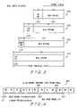
- FIG. 1is a schematic diagram of a complete packet data transfer in a GPRS/EDGE radio environment.
- packet switching in the radio environmentis achieved using the concept of a packet data transfer 100 , referred to as a “temporary block flow” (TBF).
- TBFtemporary block flow
- the temporary block flow 100which includes a data transfer setup phase 102 , a data transfer phase 104 , and a data transfer teardown phase 106 , is regarded as the basic unit of data interchange within the GPRS/EDGE environment.
- temporary block flow 100may be thought of conceptually as its three components, data transfer setup phase 102 , data transfer phase 104 , and data transfer teardown phase 106 , occurring sequentially in time. It is understood that the amount of time for the setup of a temporary block flow for GPRS varies, and is dependent on channel conditions, radio resource availability, network congestion and so on.
- GPRS and EDGEhave been specified with the objective of interchanging packet based user data, the application for most such data interchange is not of a real-time nature.
- Voice over IPpresents several challenges to the GPRS/EDGE domain, one of which is the availability of data transfer capability in the uplink direction. For example, when the mobile VoIP user speaks into the phone, a temporary block flow is required to be set up in the uplink direction as soon as possible. However, the time required by GPRS and EDGE to set up such an uplink temporary block flow is prohibitive when compared to the generally accepted maximum turnaround delay for voice telephony, which is 125 ms. Furthermore, VoIP telephony would require the addition of other mechanisms which would enable the radio layers to have knowledge of the type of information they are carrying at any given time.
- the amount of time required for data transfer setup phase 104has proven to be excessively long, resulting in problems associated with both round-trip turnaround time, and throughput, as a function of the duty-cycle reduction required for setting up an acknowledgement at the upper (network) layers, e.g. the transport layer.
- FIG. 1is a schematic diagram of a complete packet data transfer in a radio environment.
- FIG. 2is a schematic diagram of a GPRS system according to the present invention.
- FIG. 3is a schematic diagram of modification of a user data stream as the user data stream passes through specified layers of a GPRS system.
- FIG. 4is a schematic diagram of a multiframe structure for packet data channels.
- FIG. 5is a data flow diagram of stream-oriented data transmitted between a mobile station and a network.
- FIG. 6is a schematic diagram of a dynamic timeslot allocation for medium access control.
- FIG. 7is a schematic diagram of a fixed timeslot allocation for medium access control.
- FIG. 8is a schematic diagram of signaling logic for establishing an uplink packet data transfer.
- FIG. 9is a flowchart of indirect carrier sense multiple access with directed acknowledgement in a mobile station.
- FIG. 10is a flowchart of indirect carrier sense multiple access with directed acknowledgement in a base station
- the present inventionis related for allowing mobile stations to more rapidly set up an uplink packet data transfer in a GPRS/EDGE system using an indirect carrier sense multiple access with directed acknowledgement (ICSMA/DA), whereby the mobile station would be notified of when a transmit resource is not in use, allowing the mobile station to transmit on this resource only if a downlink transfer is in progress and then acknowledging the mobile station's access to the medium directly.
- ICSMA/DAindirect carrier sense multiple access with directed acknowledgement
- FIG. 2is a schematic diagram of a GPRS system according to the present invention.
- a GPRS system 200includes a mobile station 202 sending and receiving packet data from an internet application 204 to a remote internet application 206 through a base station system 208 . While a single base station system 208 and mobile station 202 is illustrated in FIG. 2 , it is understood that GPRS system 200 includes multiple numbers of base station systems and mobile stations.
- Mobile station 202includes a GPRS/EDGE subsystem 210 for processing signaling messages received from base station system 208 , and signals received from internet application 204 through transport and network layers 212 .
- GPRS/EDGE subsystem 210includes a medium access control (MAC) layer 211 , and adds header overhead for sub-network convergence/divergence protocol (SNDCP), and logical link control (LLC).
- a protocol control unit 214includes a medium access control layer 213 , and is coupled to or contained within base station system 208 , and interfaces with GPRS/EDGE subsystem 210 of mobile station 202 , and with internet application 206 through transport and network layers 216 .
- Internet transport layers 212 and 216include a transmission control protocol (TCP) layer 218 which TCP packetizes stream-oriented user data, and an internet protocol (IP) layer 220 which assigns an address to the packetized data.
- TCPtransmission control protocol
- IPinternet protocol
- FIG. 3is a schematic diagram of modification of a user data stream as the user data stream passes through specified layers of a GPRS system.
- a user data stream of infinite lengthis modified as the user data stream passes through GPRS system 200 .
- the data streamis divided into a TCP packet 222 that includes a payload 224 that is 536 octets in length and a transmission control protocol header packet 226 that is twenty octets in length, giving TCP packet 222 a total length of 556 octets.
- an additional twenty octet internet protocol header 228is appended to TCP packet 222 , forming an IP packet 230 having a total length of 576 octets.
- An additional four octet SNDCP header 232is appended to IP packet 230 , forming an SNDCP packet 234 having a total length of 580 octets, and an additional four octet logical link control header 236 is appended to SNDCP packet 234 forming a logical link control packet 238 having a total length of 584 octets.
- the user data streamhas a total length of 584 octets as the data stream exits logical link control.
- radio link controldivides the 584 octet logical link control packet 238 into a certain number of radio link control data blocks, the exact number of which depends upon the channel coding scheme used. For example, in a CS-1 channel coding scheme, the number of radio link control blocks needed is equal to (LLC frame length/RLC payload length)+(LLC frame length MOD RLC payload length), which for the 584 octet logical link control frame is equal to 31 radio link control blocks.
- the number of radio link control blocks neededis equal to (LLC frame length/RLC payload length)+(LLC frame length MOD RLC payload length), which for the 584 octet logical link control frame is equal to 21 radio link control blocks.
- FIG. 4is a schematic diagram of a multiframe structure for packet data channels. Assuming a perfect schedule of one radio link control block transmitted on each available block period for a single timeslot transfer, raw throughput may be computed based upon the length of time required to send a certain number of radio link control data blocks. As illustrated in FIG. 5 , a packet data control channel is organized as a multiframe 260 having fifty-two frames 262 and twelve data blocks B 0 –B 11 , in which each data block B 0 –B 11 is distributed over four time division multiple access (TDMA) frames.
- TDMAtime division multiple access
- An “idle” or “search” frame 264located after every three data blocks, enables the mobile station to perform adjacent cell signal measurements, synchronization and verification of synchronization status on adjacent cells, interference measurements, and so forth.
- Each data block B 0 –B 11is made up of four frames, each of which has a frame period f equal to 4.61538 milliseconds, and a block period b that is equal to 18.4616 milliseconds, while each idle frame 264 has an idle frame period I that is equal to the frame period f, or 4.61538 milliseconds.
- the total period of the multiframe 260 structure of the packet data channelis equal to 240 milliseconds.
- the time required to send all of the radio link control blocks in a logical link control frame in a CS-1 coding schemeis equal to 0.618462 sec.
- the throughputis the number of payload octets (584) divided by the time required to send them plus their overhead (0.618462) times 8 bits per octet, which is equal to 7000 bits/second.
- theoretical throughputis approximately equal to 9050 bits/sec.
- the overhead of schedulingi.e. the fact that there are idle frames that prevent the scheduling of every consecutive block reduces the effective throughput by 4/52 to approximately 8861 bits/second.
- radio link control headersi.e. three octets per block
- the overhead of the logical link control headerfour octets
- the overhead of the SNDCP header, 4 octetsreduces the effective throughput by 4/580 to approximately
- the overhead of the Internet protocol suitei.e. TCP and IP headers, reduces the effective throughput by 40/576 to approximately 7000 bits/second.
- the time required to send all of the radio link control blocks in a logical link control frame (i.e. 21 blocks) in a CS-2 coding schemeis equal to 0.42 second, and the throughput is the number of payload octets (584) divided by the time required to send them plus their overhead (0.42) times 8 bits per octet, which is equal to 10,209 bits/second.
- Theoretical throughput on channel at CS-2is approximately equal to 13,400 bits/sec.
- the overhead of schedulingi.e. the fact that there are idle frames that prevent the scheduling of every consecutive block reduces the effective throughput by 4/52 to approximately 12,369 bits/second.
- the overhead of radio link control headersi.e.
- FIG. 5is a data flow diagram of stream-oriented data transmitted between a mobile station and a network.
- stream-oriented data 213is transmitted from remote internet application 206 to mobile station 202 during a downlink period 300 for sending data long a downlink
- the datais first divided into packets at TCP layer 218 , and given an address at IP layer 220 of transport and network layer 216 , and sent to protocol control unit 214 of base station system 208 as a TCP/IP packet 302 .
- TCP/IP packet 302includes overhead associated with logical link control packet 238 and SNDCP packet 234 , and it is assumed that for every TCP/IP packet 302 , there is a corresponding logical link control packet 238 and SNDCP packet 234 as well.
- the actions associated with transmitting the information over the air interfacebegin when a logical link control frame containing the user information in the form of an encapsulated transport/network/SNDCP packet enters protocol control unit 214 of base station system 208 .
- base station system 208begins a setup sequence of a downlink setup period 224 by sending a package paging request 215 to GPRS/EDGE subsystem 210 of mobile station 202 .
- protocol control unit 214sends an immediate assignment message 219 and a packet downlink message 221 , detailing the parameters of the assignment, e.g. over what channel the transfer would take place, when the transfer would start, and so on.
- Protocol control unit 214sends a series of radio link control data blocks 226 to GPRS/EDGE subsystem 210 after receiving a packet control acknowledge message 222 from GPRS/EDGE subsystem 210 .
- packet paging request message 215may require from 81 to 1721 ms, followed by random access burst 217 from mobile station 102 , which typically requires 9.6 ms.
- Immediate assignment message 219contains a starting time that may range from 37 ms to 3 minutes in the future, but typically ranges from 13 to 25 TDMA frame periods, or 60–115 ms.
- Additional signaling associated with exchanging packet downlink assignment message 221 and a packet control acknowledgement message 222are included in downlink setup period 224 . It is therefore assumed that downlink setup period 224 may be equal to a starting time, which is in fact what is observable in an actual system. As a result, the time required for downlink setup period 224 is a minimum of approximately 849 ms, a maximum of approximately 2643 ms and an average of approximately 1746 ms.
- protocol control unit 218sends GPRS/EDGE subsystem 210 a temporary block flow containing radio link control data blocks 226 .
- GPRS/EDGE subsystem 210assembles, processes and transmits a resulting single data packet 228 to IP layer 220 of transport and network layers 212 , which then sends data packet 228 to TCP layer 218 of transport and network layers 212 .
- the time to transmit all blocks during data transfer period 225 for a 536 octet user data payloadis approximately equal to 0.618462 seconds for a CS-1 coding scheme, and 0.420 seconds for a CS-2 coding scheme.
- the downlink temporary block flowterminates after a last radio link control data block is sent if sending radio link control on protocol control unit 214 has no more data to be sent and a radio link controller timer T 3192 expires before radio link control receives more data to be sent from logical link control, which is the case when a transmission control protocol transmission starts in “congestion control” (slow-start) mode.
- the temporary block flowis always torn down after the blocks making up the first transmission control protocol packet are transmitted, causing the downlink temporary block flow to incur the overhead of temporary block flow being setup again for the subsequent blocks.
- TCP layer 218 of transport and network layers 212performs redundancy checking and makes a determination that data packet 228 has been received properly.
- IP layer 220 of transport and network layers 212then includes the packet data in a stream-oriented output 230 to internet application 204 and issues a TCP acknowledgement (TCP ACK) message 232 to TCP layer 218 of transport and network layers 216 on the far end of the virtual circuit.
- TCP ACK message 232is processed by SNDCP/LLC and RLC layers as before, but in an uplink direction.
- Radio link controller of GPRS/EDGE subsystem 210 of remote transport and network layers 216receives a TCP/IP/SNDCP/LLC packet containing TCP ACK message 232 , but cannot begin a setup sequence corresponding to an uplink setup period 234 for transmission of TCP ACK message 232 until a radio link control timer T 3192 of protocol control unit 114 has expired.
- a downlink temporary block flow corresponding to downlink period 300 that carries TCP/IP packet 302 that was initially sentmust be torn down completely before uplink period 234 for setting up TCP ACK message 232 may begin.
- GPRS/EDGE subsystem 210upon receiving TCP ACK message 232 , GPRS/EDGE subsystem 210 sends a channel request access burst 236 to protocol control unit 214 , which responds by sending an immediate assignment message 238 . GPRS/EDGE subsystem 210 then sends a packet resource request message 240 to protocol control unit 214 requesting resources for a temporary block flow. Protocol control unit 214 responds with a packet uplink assignment message 242 , which is acknowledged by GPRS/EDGE subsystem 210 in a packet control acknowledge message 244 . Data blocks 246 containing TCP ACK message 232 and teardown are then transmitted from GPRS/EDGE subsystem 210 to protocol control unit 214 during an acknowledge data transfer period 248 .
- Protocol control unit 214then transmits data blocks 246 to transport and network layers 216 in a TCP acknowledge message 304 .
- uplink setup period 234 and acknowledge data transfer period 248form an uplink period 306 that is required for TCP acknowledge message 232 to reach transport and network layer 216 in corresponding TCP acknowledge message 304 .
- a next TCP/IP data packet message 250is sent from transport and network layers 216 to GPRS/EDGE subsystem 210 via protocol control unit 214 .
- the period required for the initial setup of uplink setup period 234is dependent upon components such as the periodic occurrence of a random access channel (RACH), the starting time sent in immediate assignment message 238 , and the starting time sent in packet uplink assignment message 242 .
- the periodic occurrence of a random access channelcan range from 41–217 TDMA frame periods, assuming a case of 41 frame periods, or 190 ms.
- the starting time sent in immediate assignment message 238may range from 9 TDMA frame periods to 3 minutes, but is typically from 9–25 TDMA frame periods, or 42–115 ms, while the starting time sent in packet uplink assignment message 242 may range from 9 TDMA frame periods to 3 minutes, but is typically around 20 TDMA periods, or 92 ms.
- initial setup of uplink setup period 234is typically a minimum of approximately 320 ms, a maximum of approximately 480 ms, and an average of approximately 320 ms. This exceeds the generally accepted maximum end to end delay of 125 milliseconds.
- TCP ACK message 232has a length of 40 octets, which combined with the overhead of both logical link control header 236 and SNDCP header 232 is equal to 48 octets. Assuming perfectly available radio resources so that data may be sent on every schedulable downlink block on a single timeslot, the time to transmit all data blocks 246 during acknowledge data transfer period 248 for a 40 octet TCP/IP ACK payload is equal to 60 ms (3 RLC data blocks) for the CS-1 coding scheme, and 37 ms (2 RLC data blocks) for the CS-2 coding scheme.
- FIG. 6is a schematic diagram of a dynamic timeslot allocation for medium access control.
- a mobile station 300receives a downlink radio link control/medium access control (RLC/MAC) control block 302 from a base station 304 that includes a special address, referred to as an uplink state flag (USF) 306 , along with RLC/MAC data 308 .
- RLC/MACradio link control/medium access control
- USF 306(a 3-bit quantity) is identical to that of a USF assigned to mobile station 300 , then mobile station 300 has the right to transmit in the next time division multiple access (TDMA) frame.
- a data block addressed to a second mobile station 310may contain USF information for mobile station 300 .
- FIG. 7is a schematic diagram of a fixed timeslot allocation for medium access control.
- a mobile station 312periodically receives a starting time and a bit-map 314 from a base station 316 , representing a base and offset of future timeslots on which the mobile station is to transmit.
- mobile station 312is informed of when temporary block flow starts and receives bitmap 314 representing timeslots on which mobile station 312 is to transmit relative to the starting time, so that mobile station 312 transmits in timeslots assigned by the starting time and allocation bitmap.
- the present inventionutilizes a USF field for both fixed and dynamic allocation MAC mode, when the mobile station is not engaged in an uplink temporary block flow, although USF value is given a different meaning, as described below.
- the present inventionincludes a collision avoidance (CA) mechanism that utilizes the already-present USF address in the RLC/MAC control block to enable the rapid creation of an uplink temporary block flow, when there is already a downlink temporary block flow in progress. Since the USF value is receivable by multiple mobile stations on the radio resource, the USF value assignment serves as an indirect lock on the resource.
- CAcollision avoidance
- the USF fieldis recognized during an active downlink temporary block flow as a “channel availability” indicator and a “directed acknowledgement field”.
- FIG. 8is a schematic diagram of signaling logic for establishing an uplink packet data transfer according to the present invention.
- the mobile stationwhen receiving blocks comprising a downlink temporary block flow, examines the USF field when it has information to transmit in an uplink temporary block flow. If the USF were a zero value, then the channel would be evaluated as “available”, and the mobile station may therefore begin transmitting its new uplink TBF information.
- a base station 320 and a mobile station 322are in a downlink temporary block flow setup 324 of downlink setup period 224 , which includes the assignment of a mobile station USF address, such as “110”, for example, base station 320 , through medium access control layer 213 , sends a USF address to mobile station 322 by which mobile station 322 will be identified for the duration of the downlink temporary block flow for data transfer period 225 resulting from downlink temporary block flow setup 324 , along with a contingent uplink timeslot number on which mobile station 322 may transmit.
- a mobile station USF addresssuch as “110”
- base station 320through medium access control layer 213 , sends a USF address to mobile station 322 by which mobile station 322 will be identified for the duration of the downlink temporary block flow for data transfer period 225 resulting from downlink temporary block flow setup 324 , along with a contingent uplink timeslot number on which mobile station 322 may transmit.
- Base station 320receives the first uplink data block 328 and knows how to associate a temporary flow identifier (TFI) to a USF value of mobile station 322 .
- Base station 320acknowledges the USF address of mobile station 322 in the next downlink radio link control data block 330 by inserting the USF value (that serves to indirectly address a mobile station) of mobile station 322 into the header of next downlink radio link control data block 330 .
- the inserted USF valueserves as an acknowledgement to the sending mobile station 322 and as a “channel busy” indication to other mobiles desiring to transmit.
- Mobile station 322through medium access layer 211 , interprets next downlink radio link control data block 330 with a USF value located in a header at the beginning of radio link control data block 330 as an acknowledgement that the first uplink data block 328 was correctly received by base station 320 , and sends a subsequent uplink radio link control block 332 . This procedure is then continued for the remaining portion 343 of the uplink temporary block flow 248 , until the end of uplink temporary block flow 248 , which is indicated in the usual manner to base station 320 by the countdown procedure in the last several radio link control data blocks.
- mobile station 322In the countdown procedure, mobile station 322 , during transmission of the last few data blocks 246 , decrements a variable in the header of data blocks 246 to inform base station 320 that the uplink data block flow is about to end. This knowledge helps base station 320 allocate to another mobile station.
- mobile station 322when receiving blocks comprising a downlink temporary block flow, would examine the USF field when mobile station 322 has information to transmit in an uplink temporary block flow. If the USF is a zero value, then the channel would be evaluated by mobile station 322 as being “available”, and mobile station 322 may therefore begin transmitting new uplink temporary block flow information.
- Base station 320acknowledges receipt of the uplink data blocks 328 , 332 , 336 , 340 and so forth, by sending a direct acknowledgement in respective downlink radio link control blocks 330 , 334 , 338 , 342 and so forth.
- the present inventionutilizes the packet data traffic channel (PDTCH), rather than a random access channel, since the synchronization between mobile station 322 and base station 320 is already known. There is therefore no need for the special shortened GSM “access burst” to be used. As a result, an initial radio link control block data block (and therefore user information) may be sent along with the uplink access procedure, further streamlining uplink access.
- the generally used GSM uplink access methodis shown in FIG. 5 and includes exchange of channel request access burst 236 , immediate assignment message 238 , packet resource request 240 , and packet uplink assignment 242 . In this way, the present invention removes the need for this interchange.
- FIG. 9is a flowchart of indirect carrier sense multiple access with directed acknowledgement in a mobile station, according to the present invention.
- mobile station 322determines whether mobile station 322 has data available to transmit on the uplink, Step 342 . Once mobile station 322 has data to transmit on the uplink, mobile station 322 then determines whether downlink temporary block flow setup 324 has been completed, Step 344 . If downlink temporary block flow setup 324 has not been completed, mobile station 322 waits, Step 340 , until downlink temporary block flow setup 324 is completed.
- Step 344mobile station 322 determines whether downlink radio link control block 326 has been received, Step 346 . If downlink radio link control block 326 has not been received, the process returns to Step 340 so that mobile station 322 waits until downlink radio link control block 326 is received. If downlink radio link control block 326 has been received, mobile station 322 determines whether USF contained within downlink radio link control block 326 is equal to zero, Step 348 , which indicates that base station 320 has indicated to mobile station that an uplink channel is available and is not being utilized by any mobile station.
- uplink channelis available, i.e., USF contained within downlink radio link control block 326 is equal to zero in Step 348 , mobile station 322 sends first uplink radio link control block 328 to base station using uplink channel, Step 354 . Once mobile station 322 sends uplink radio link control block 328 to base station 320 in Step 354 , the process returns to Step 340 , and the process continues for the next uplink radio link control block.
- mobile station 322determines whether USF of downlink radio link control block is equal to identifier of mobile station 322 , which indicates that mobile station 322 can transfer the next data block.
- FIG. 10is a flowchart of indirect carrier sense multiple access with directed acknowledgement in a base station, according to the present invention.
- base station 320determines whether a channel is allocated to mobile station 322 in an uplink temporary block flow, Step 362 . If a channel has already been allocated, the process returns to the start, Step 360 . If a channel has not been allocated, base station 320 determines whether uplink radio link control block 328 has been received from mobile station 322 , Step 364 .
- base station 320sets the USF in downlink radio link control block 326 equal to zero, Step 370 , and sends downlink radio link control block 326 , Step 372 .
- the processthen returns to Step 360 so that base station 320 continues to send an indication of uplink channel availability to mobile station 322 in subsequent downlink radio control blocks until base station 320 receives the initial uplink radio link control data block on the timeslot allocated by base station 320 as a contingent uplink timeslot number.
- base station 320determines in Step 364 that uplink radio link control block 328 has been received, base station 320 then makes a determination as to whether uplink radio link control block 328 has a USF value equal to a mobile station having a valid downlink temporary block flow, Step 366 . If uplink radio link control block 328 does not have a USF value equal to a mobile station having a valid downlink temporary block flow, the process returns to Step 370 , so that base station 320 continues to send an indication of uplink channel availability to mobile station 322 in subsequent downlink radio control blocks until base station 320 receives the next uplink radio link control data block on the timeslot allocated by base station 320 as a contingent uplink timeslot number.
- uplink radio link control block 328does have a USF value equal to a mobile station having a valid downlink temporary block flow in Step 366 , base station 320 sets the USF value in the downlink radio link control data block 330 to the value of USF in mobile station 322 .
- the USF value in mobile station 322is “110” as indicated in downlink temporary block flow setup 324 .
- Base stationthen sends downlink radio link control data block 330 with USF equal to “110” as a directed acknowledgement of the USF of mobile station 322 .
- Step 360The process then returns to Step 360 so that base station 320 waits for receipt of subsequent uplink radio link control data block 322 in Step 364 , and the process continues until the end of the associated uplink temporary block flow indicated by the countdown procedure in the last several radio link control data blocks of the uplink data transfer by mobile station 322 , or until mobile station 322 no longer has data to transmit.
Landscapes
- Engineering & Computer Science (AREA)
- Computer Networks & Wireless Communication (AREA)
- Signal Processing (AREA)
- Computer Security & Cryptography (AREA)
- Mobile Radio Communication Systems (AREA)
- Small-Scale Networks (AREA)
- Data Exchanges In Wide-Area Networks (AREA)
Abstract
Description
TR=(Nb×b)+((Nb/3)×f)
while the raw data throughput Rdis calculated using the following equation:
Rd=(number of payload octets/TR)×8 EQUATION 2
Claims (20)
Priority Applications (9)
| Application Number | Priority Date | Filing Date | Title |
|---|---|---|---|
| US09/599,355US7181223B1 (en) | 2000-06-21 | 2000-06-21 | Method for rapid uplink access by GSM GPRS/EDGE mobile stations engaged in voice over internet protocol packet transfer mode |
| AT01941922TATE534260T1 (en) | 2000-06-21 | 2001-06-05 | METHOD AND FAST UPWARD ACCESS THROUGH GSM-GPRS/EDGE MOBILE STATIONS INVOLVED IN VOICE OVER INTERNET PROTOCOL PACKET TRANSFER MODE |
| BRPI0111888-9ABRPI0111888B1 (en) | 2000-06-21 | 2001-06-05 | Method for fast uplink access by gsm gprs / edge mobile stations engaged in voice over internet protocol packet transfer mode |
| EP01941922AEP1348261B1 (en) | 2000-06-21 | 2001-06-05 | Method and rapid uplink access by gsm gprs/edge mobile stations engaged in voice over internet protocol packet transfer mode |
| JP2002504558AJP4850383B2 (en) | 2000-06-21 | 2001-06-05 | Method for high speed uplink access by a GSGPRS / EDGE mobile station used in voice over internet protocol packet transfer mode |
| CNB01811489XACN1251422C (en) | 2000-06-21 | 2001-06-05 | Rapid uplink access by GSM GPRS/EDGE mobile stations engaged in voice packet transfer |
| AU2001275233AAU2001275233A1 (en) | 2000-06-21 | 2001-06-05 | Method and rapid uplink access by gsm gprs/edge mobile stations engaged in voiceover internet protocol packet transfer mode |
| PCT/US2001/018120WO2001098863A2 (en) | 2000-06-21 | 2001-06-05 | Rapid uplink access by gsm gprs/edge mobile stations engaged in voip packet transfer |
| KR1020027017429AKR100564860B1 (en) | 2000-06-21 | 2001-06-05 | High-speed uplink access method by a GSM GPRS / EDGE mobile station communicating in Internet-based voice communication protocol packet delivery mode |
Applications Claiming Priority (1)
| Application Number | Priority Date | Filing Date | Title |
|---|---|---|---|
| US09/599,355US7181223B1 (en) | 2000-06-21 | 2000-06-21 | Method for rapid uplink access by GSM GPRS/EDGE mobile stations engaged in voice over internet protocol packet transfer mode |
Publications (1)
| Publication Number | Publication Date |
|---|---|
| US7181223B1true US7181223B1 (en) | 2007-02-20 |
Family
ID=24399285
Family Applications (1)
| Application Number | Title | Priority Date | Filing Date |
|---|---|---|---|
| US09/599,355Expired - LifetimeUS7181223B1 (en) | 2000-06-21 | 2000-06-21 | Method for rapid uplink access by GSM GPRS/EDGE mobile stations engaged in voice over internet protocol packet transfer mode |
Country Status (9)
| Country | Link |
|---|---|
| US (1) | US7181223B1 (en) |
| EP (1) | EP1348261B1 (en) |
| JP (1) | JP4850383B2 (en) |
| KR (1) | KR100564860B1 (en) |
| CN (1) | CN1251422C (en) |
| AT (1) | ATE534260T1 (en) |
| AU (1) | AU2001275233A1 (en) |
| BR (1) | BRPI0111888B1 (en) |
| WO (1) | WO2001098863A2 (en) |
Cited By (20)
| Publication number | Priority date | Publication date | Assignee | Title |
|---|---|---|---|---|
| US20030202490A1 (en)* | 2002-04-24 | 2003-10-30 | Fredrik Gunnarsson | Method and apparatus for uplink transmission timing in a mobile communications system |
| US20040047343A1 (en)* | 2002-08-14 | 2004-03-11 | Evolium S.A.S. | Method for allocating resources in packet mode in a mobile radio system |
| US20050207359A1 (en)* | 2004-03-16 | 2005-09-22 | Nokia Corporation | Enhanced uplink dedicated channel - application protocol over lub/lur |
| US20060045010A1 (en)* | 2002-08-13 | 2006-03-02 | Koninklijke Philips Electronics N.V. | Arq system with status and packet acknowledgement |
| US20060168313A1 (en)* | 2002-12-06 | 2006-07-27 | Robinson Nigel P | Method of and apparatus for adaptive control of data buffering in a data transmitter |
| US20060268774A1 (en)* | 2005-05-23 | 2006-11-30 | Kangas Antti O | Method and equipment for indicating and MBMS assignment via common control channel |
| US20080165744A1 (en)* | 2000-07-24 | 2008-07-10 | Nokia Corporation | Sending permission assignment in telecommunications system |
| US20080285523A1 (en)* | 2005-11-01 | 2008-11-20 | Telefonaktiebolaget L M Ericsson (Publ) | Method And Arrangements In A Radio Communication System |
| US20090137254A1 (en)* | 2007-11-28 | 2009-05-28 | Motorola, Inc. | Techniques for aligning application output and uplink resource allocation in wireless communication systems |
| US20090154443A1 (en)* | 1998-11-27 | 2009-06-18 | Mika Forssell | Method and arrangement for transferring information in a packet radio service |
| US7561523B1 (en)* | 2001-11-15 | 2009-07-14 | Netapp, Inc. | Method and apparatus for flow control in a reliable multicast communication system |
| US20090232059A1 (en)* | 2004-12-13 | 2009-09-17 | Telefonaktiebolaget Lm Ericsson (Publ) | Latency Reduction When Setting Up An Uplink Wireless Communications Channel |
| US20090323671A1 (en)* | 2008-06-30 | 2009-12-31 | Chih-Hsiang Wu | Method for determining rlc data pdu size in wireless communications system according to control data |
| US20100180058A1 (en)* | 2006-12-15 | 2010-07-15 | Akihiro Ihori | Communication System, Communication Apparatus, Communication Method, and Computer Program |
| US20120023235A1 (en)* | 2010-07-22 | 2012-01-26 | David Philip Hole | Methods and apparatus to poll in wireless communications |
| US20130258925A1 (en)* | 2012-03-30 | 2013-10-03 | Qualcomm Incorporated | High-speed data channel availability |
| US8830981B2 (en) | 2010-07-22 | 2014-09-09 | Blackberry Limited | Methods and apparatus to poll in wireless communications based on assignments |
| US8837388B2 (en) | 2010-07-22 | 2014-09-16 | Blackberry Limited | Methods and apparatus to perform assignments in wireless communications |
| US9001649B2 (en) | 2010-07-22 | 2015-04-07 | Blackberry Limited | Methods and apparatus to communicate data between a wireless network and a mobile station |
| US10298970B2 (en) | 2014-12-12 | 2019-05-21 | Huawei Technologies Co., Ltd. | Image transmission method and apparatus |
Families Citing this family (7)
| Publication number | Priority date | Publication date | Assignee | Title |
|---|---|---|---|---|
| US7869417B2 (en)* | 2005-07-21 | 2011-01-11 | Qualcomm Incorporated | Multiplexing and feedback support for wireless communication systems |
| CN101043299B (en)* | 2006-04-05 | 2010-08-25 | 华为技术有限公司 | ACK/NACK method |
| US20080025247A1 (en)* | 2006-07-28 | 2008-01-31 | Motorola, Inc. | Indicating special transmissions in wireless communication systems |
| CN100446588C (en)* | 2006-08-14 | 2008-12-24 | 华为技术有限公司 | Packet wireless data transmission method and system between base station and base station controller |
| CN101136727B (en)* | 2006-09-01 | 2010-05-12 | 华为技术有限公司 | A method of reporting whether data is received correctly |
| CN101931898B (en)* | 2009-06-26 | 2014-03-05 | 华为技术有限公司 | User plane data transmission method, device and system |
| KR101651025B1 (en)* | 2012-08-23 | 2016-08-24 | 퀄컴 인코포레이티드 | In-band signaling to indicate end of data stream and update user context |
Citations (11)
| Publication number | Priority date | Publication date | Assignee | Title |
|---|---|---|---|---|
| US6282182B1 (en)* | 2000-01-07 | 2001-08-28 | Motorola, Inc. | Method and apparatus for simultaneous circuit switched voice and GPRS data interchange |
| US6310866B1 (en)* | 1998-10-09 | 2001-10-30 | Telefonaktiebolaget Lm Ericsson (Publ) | Medium access control protocol with automatic frequency assignment |
| US6356759B1 (en)* | 1997-03-27 | 2002-03-12 | Nokia Telecommunications Oy | Resource allocation mechanism in packet radio network |
| US6396827B1 (en)* | 1998-06-16 | 2002-05-28 | Nokia Corporation | Multi-mode mobile apparatus and method for calculating frame/time slot offsets, and allowing mobiles to synchronize with different mobile protocols/schemes |
| US6526033B1 (en)* | 1999-09-17 | 2003-02-25 | Lucent Technologies Inc. | Delivering calls to GSM subscribers roaming to CDMA networks via IP tunnels |
| US6529525B1 (en)* | 2000-05-19 | 2003-03-04 | Motorola, Inc. | Method for supporting acknowledged transport layer protocols in GPRS/edge host application |
| US6577619B2 (en)* | 1997-03-27 | 2003-06-10 | Nokia Corporation | Packet transmission in mobile telecommunications systems |
| US6606311B1 (en)* | 1999-04-20 | 2003-08-12 | Nortel Networks Limited | QoS framework for CDMA 2000 |
| US6625133B1 (en)* | 1998-05-17 | 2003-09-23 | Lucent Technologies Inc. | System and method for link and media access control layer transaction initiation procedures |
| US6631259B2 (en)* | 2000-03-31 | 2003-10-07 | Motorola, Inc. | Method for enabling receipt of a packet-switched page by a mobile station |
| US6671511B1 (en)* | 1998-11-27 | 2003-12-30 | Nokia Mobile Phones Ltd. | Method and arrangement for transferring information in a packet radio service |
Family Cites Families (5)
| Publication number | Priority date | Publication date | Assignee | Title |
|---|---|---|---|---|
| FI98427C (en)* | 1994-06-08 | 1997-06-10 | Nokia Mobile Phones Ltd | Systems for transmitting packet data with different bit rates in a cellular TDMA system |
| JP3003580B2 (en)* | 1996-07-24 | 2000-01-31 | 日本電気株式会社 | Data transmitting / receiving device and data communication system using the same |
| KR100283073B1 (en)* | 1997-10-13 | 2001-03-02 | 정선종 | A trnsmit and receive method of control plane information using the structure of medium access control frame |
| US6131012A (en)* | 1998-05-26 | 2000-10-10 | Nera Wireless Broadband Access As | Method and system for a micro-channel bank for providing voice, data, and multimedia services in a wireless local loop system |
| EP1005243A1 (en)* | 1998-11-24 | 2000-05-31 | TELEFONAKTIEBOLAGET LM ERICSSON (publ) | Access method for mobile telecommunication system |
- 2000
- 2000-06-21USUS09/599,355patent/US7181223B1/ennot_activeExpired - Lifetime
- 2001
- 2001-06-05EPEP01941922Apatent/EP1348261B1/ennot_activeExpired - Lifetime
- 2001-06-05CNCNB01811489XApatent/CN1251422C/ennot_activeExpired - Lifetime
- 2001-06-05WOPCT/US2001/018120patent/WO2001098863A2/enactiveIP Right Grant
- 2001-06-05AUAU2001275233Apatent/AU2001275233A1/ennot_activeAbandoned
- 2001-06-05KRKR1020027017429Apatent/KR100564860B1/ennot_activeExpired - Lifetime
- 2001-06-05JPJP2002504558Apatent/JP4850383B2/ennot_activeExpired - Lifetime
- 2001-06-05BRBRPI0111888-9Apatent/BRPI0111888B1/enactiveIP Right Grant
- 2001-06-05ATAT01941922Tpatent/ATE534260T1/enactive
Patent Citations (11)
| Publication number | Priority date | Publication date | Assignee | Title |
|---|---|---|---|---|
| US6356759B1 (en)* | 1997-03-27 | 2002-03-12 | Nokia Telecommunications Oy | Resource allocation mechanism in packet radio network |
| US6577619B2 (en)* | 1997-03-27 | 2003-06-10 | Nokia Corporation | Packet transmission in mobile telecommunications systems |
| US6625133B1 (en)* | 1998-05-17 | 2003-09-23 | Lucent Technologies Inc. | System and method for link and media access control layer transaction initiation procedures |
| US6396827B1 (en)* | 1998-06-16 | 2002-05-28 | Nokia Corporation | Multi-mode mobile apparatus and method for calculating frame/time slot offsets, and allowing mobiles to synchronize with different mobile protocols/schemes |
| US6310866B1 (en)* | 1998-10-09 | 2001-10-30 | Telefonaktiebolaget Lm Ericsson (Publ) | Medium access control protocol with automatic frequency assignment |
| US6671511B1 (en)* | 1998-11-27 | 2003-12-30 | Nokia Mobile Phones Ltd. | Method and arrangement for transferring information in a packet radio service |
| US6606311B1 (en)* | 1999-04-20 | 2003-08-12 | Nortel Networks Limited | QoS framework for CDMA 2000 |
| US6526033B1 (en)* | 1999-09-17 | 2003-02-25 | Lucent Technologies Inc. | Delivering calls to GSM subscribers roaming to CDMA networks via IP tunnels |
| US6282182B1 (en)* | 2000-01-07 | 2001-08-28 | Motorola, Inc. | Method and apparatus for simultaneous circuit switched voice and GPRS data interchange |
| US6631259B2 (en)* | 2000-03-31 | 2003-10-07 | Motorola, Inc. | Method for enabling receipt of a packet-switched page by a mobile station |
| US6529525B1 (en)* | 2000-05-19 | 2003-03-04 | Motorola, Inc. | Method for supporting acknowledged transport layer protocols in GPRS/edge host application |
Non-Patent Citations (2)
| Title |
|---|
| Draft ETSI EN 300 911 V6.5.0 (1999-07) Title: Digital Cellular Telecommunications System (Phase 2+) Radio Sybsystem Link Control (GSM 05.08 Version 6.5.0 Release 1997). |
| Draft ETSI EN 301 349 V6.4.0 (1999-07) Title: Digital Cellular Telecommunications System (Phase 2+) General Packet Radio Service (GPRS); Mobile Station (MS)-Base Station System (BSS) Interface; Radio Link Control/Medium Access Control (RLC/MAC) Protocol (GSM 04.60 Version 6.4.0 Release 1997). |
Cited By (44)
| Publication number | Priority date | Publication date | Assignee | Title |
|---|---|---|---|---|
| US20140056133A1 (en)* | 1998-11-27 | 2014-02-27 | Intellectual Ventures I Llc | Method and arrangement for transferring information in a packet radio service |
| US8213304B2 (en)* | 1998-11-27 | 2012-07-03 | Intellectual Ventures I Llc | Method and arrangement for transferring information in a packet radio service |
| US20120224479A1 (en)* | 1998-11-27 | 2012-09-06 | Mika Forssell | Method and arrangement for transferring information in a packet radio service |
| US8531949B2 (en)* | 1998-11-27 | 2013-09-10 | Intellectual Ventures I Llc | Method and arrangement for transferring information in a packet radio service |
| US9001652B2 (en)* | 1998-11-27 | 2015-04-07 | Intellectual Ventures I Llc | Method and arrangement for transferring information in a packet radio service |
| US20090154443A1 (en)* | 1998-11-27 | 2009-06-18 | Mika Forssell | Method and arrangement for transferring information in a packet radio service |
| US20080165744A1 (en)* | 2000-07-24 | 2008-07-10 | Nokia Corporation | Sending permission assignment in telecommunications system |
| US8571055B2 (en) | 2000-07-24 | 2013-10-29 | Nokia Corporation | Sending permission assignment in telecommunications system |
| US7561523B1 (en)* | 2001-11-15 | 2009-07-14 | Netapp, Inc. | Method and apparatus for flow control in a reliable multicast communication system |
| US8009607B2 (en)* | 2002-04-24 | 2011-08-30 | Telefonaktiebolaget Lm Ericsson (Publ) | Method and apparatus for uplink transmission timing in a mobile communications system |
| US20030202490A1 (en)* | 2002-04-24 | 2003-10-30 | Fredrik Gunnarsson | Method and apparatus for uplink transmission timing in a mobile communications system |
| US20060045010A1 (en)* | 2002-08-13 | 2006-03-02 | Koninklijke Philips Electronics N.V. | Arq system with status and packet acknowledgement |
| US8315210B2 (en)* | 2002-08-13 | 2012-11-20 | Koninklijke Philips Electronics N.V. | ARQ system with status and packet acknowledgement |
| US9025548B2 (en) | 2002-08-13 | 2015-05-05 | Koninklijke Philips N.V. | ARQ system with status and packet acknowledgement |
| US9853778B2 (en) | 2002-08-13 | 2017-12-26 | Koninklijke Philips N. V. | ARQ system with status and packet acknowledgement |
| US8903406B2 (en)* | 2002-08-14 | 2014-12-02 | Alcatel Lucent | Method for allocating resources in packet mode in a mobile radio system |
| US9999027B2 (en) | 2002-08-14 | 2018-06-12 | Alcatel Lucent | Method for allocating resources in packet mode in a mobile radio system |
| US20040047343A1 (en)* | 2002-08-14 | 2004-03-11 | Evolium S.A.S. | Method for allocating resources in packet mode in a mobile radio system |
| US8780929B2 (en)* | 2002-12-06 | 2014-07-15 | Qualcomm Incorporated | Method of and apparatus for adaptive control of data buffering in a data transmitter |
| US7860992B2 (en)* | 2002-12-06 | 2010-12-28 | Qualcomm Incorporated | Method of and apparatus for adaptive control of data buffering in a data transmitter |
| US20060168313A1 (en)* | 2002-12-06 | 2006-07-27 | Robinson Nigel P | Method of and apparatus for adaptive control of data buffering in a data transmitter |
| US20110080874A1 (en)* | 2002-12-06 | 2011-04-07 | Qualcomm Incorporated | Method of and Apparatus for Adaptive Control of Data Buffering in a Data Transmitter |
| US8243633B2 (en)* | 2004-03-16 | 2012-08-14 | Nokia Corporation | Enhanced uplink dedicated channel—application protocol over lub/lur |
| US20050207359A1 (en)* | 2004-03-16 | 2005-09-22 | Nokia Corporation | Enhanced uplink dedicated channel - application protocol over lub/lur |
| US20090232059A1 (en)* | 2004-12-13 | 2009-09-17 | Telefonaktiebolaget Lm Ericsson (Publ) | Latency Reduction When Setting Up An Uplink Wireless Communications Channel |
| US20060268774A1 (en)* | 2005-05-23 | 2006-11-30 | Kangas Antti O | Method and equipment for indicating and MBMS assignment via common control channel |
| US8638727B2 (en)* | 2005-11-01 | 2014-01-28 | Telefonaktiebolaget Lm Ericsson (Publ) | Method and arrangements in a radio communication system |
| US20080285523A1 (en)* | 2005-11-01 | 2008-11-20 | Telefonaktiebolaget L M Ericsson (Publ) | Method And Arrangements In A Radio Communication System |
| US20100180058A1 (en)* | 2006-12-15 | 2010-07-15 | Akihiro Ihori | Communication System, Communication Apparatus, Communication Method, and Computer Program |
| US8755811B2 (en) | 2007-11-28 | 2014-06-17 | Motorola Mobility Llc | Techniques for aligning application output and uplink resource allocation in wireless communication systems |
| US20090137254A1 (en)* | 2007-11-28 | 2009-05-28 | Motorola, Inc. | Techniques for aligning application output and uplink resource allocation in wireless communication systems |
| US8244265B2 (en) | 2007-11-28 | 2012-08-14 | Motorola Mobility Llc | Techniques for aligning application output and uplink resource allocation in wireless communication systems |
| US9635650B2 (en) | 2007-11-28 | 2017-04-25 | Google Technology Holdings LLC | Techniques for aligning application output and uplink resource allocation in wireless communication systems |
| US9226195B2 (en)* | 2008-06-30 | 2015-12-29 | Htc Corporation | Method for determining RLC Data PDU size in wireless communications system according to control data |
| US20090323671A1 (en)* | 2008-06-30 | 2009-12-31 | Chih-Hsiang Wu | Method for determining rlc data pdu size in wireless communications system according to control data |
| CN102883367B (en)* | 2008-06-30 | 2015-11-04 | 宏达国际电子股份有限公司 | Method and device for determining size of data packet data unit according to control data |
| US9001649B2 (en) | 2010-07-22 | 2015-04-07 | Blackberry Limited | Methods and apparatus to communicate data between a wireless network and a mobile station |
| US8745231B2 (en)* | 2010-07-22 | 2014-06-03 | Blackberry Limited | Methods and apparatus to poll in wireless communications |
| US8837388B2 (en) | 2010-07-22 | 2014-09-16 | Blackberry Limited | Methods and apparatus to perform assignments in wireless communications |
| US8830981B2 (en) | 2010-07-22 | 2014-09-09 | Blackberry Limited | Methods and apparatus to poll in wireless communications based on assignments |
| US20120023235A1 (en)* | 2010-07-22 | 2012-01-26 | David Philip Hole | Methods and apparatus to poll in wireless communications |
| US9185649B2 (en)* | 2012-03-30 | 2015-11-10 | Qualcomm Incorporated | High-speed data channel availability |
| US20130258925A1 (en)* | 2012-03-30 | 2013-10-03 | Qualcomm Incorporated | High-speed data channel availability |
| US10298970B2 (en) | 2014-12-12 | 2019-05-21 | Huawei Technologies Co., Ltd. | Image transmission method and apparatus |
Also Published As
| Publication number | Publication date |
|---|---|
| BR0111888A (en) | 2003-07-08 |
| EP1348261A2 (en) | 2003-10-01 |
| JP4850383B2 (en) | 2012-01-11 |
| ATE534260T1 (en) | 2011-12-15 |
| AU2001275233A1 (en) | 2002-01-02 |
| EP1348261B1 (en) | 2011-11-16 |
| WO2001098863A3 (en) | 2002-04-04 |
| KR20030013449A (en) | 2003-02-14 |
| JP2004501590A (en) | 2004-01-15 |
| EP1348261A4 (en) | 2007-09-26 |
| CN1251422C (en) | 2006-04-12 |
| KR100564860B1 (en) | 2006-03-28 |
| WO2001098863A2 (en) | 2001-12-27 |
| CN1437800A (en) | 2003-08-20 |
| BRPI0111888B1 (en) | 2015-08-25 |
Similar Documents
| Publication | Publication Date | Title |
|---|---|---|
| US7181223B1 (en) | Method for rapid uplink access by GSM GPRS/EDGE mobile stations engaged in voice over internet protocol packet transfer mode | |
| US6529525B1 (en) | Method for supporting acknowledged transport layer protocols in GPRS/edge host application | |
| US6996083B1 (en) | Burst based access and assignment method for providing real-time services | |
| RU2413393C2 (en) | Dedication of radio resources in mobile communication system | |
| US8213370B2 (en) | Method of transmitting on a random access channel based on parameter relating to performance of persistence test | |
| KR100615141B1 (en) | Method and apparatus for allocating transmission period in wireless telecommunication system and therefor system | |
| CA2256429C (en) | Resource allocation mechanism in packet radio network | |
| US6707808B1 (en) | Method and system for fast access to an uplink channel in a mobile communication network | |
| EP1107481A2 (en) | A system for statistically multiplexing real-time and non-real-time voice and data traffic in a wireless system | |
| US20060120339A1 (en) | Method of controlling quality of service for a wireless LAN base station apparatus | |
| US20040090948A1 (en) | Method in a communications system for assigning transmission resources | |
| EP1379033A1 (en) | Method for releasing single downlink TBFs in a mobile radio system | |
| EP1376950A1 (en) | Method for releasing single TBFs in a mobile radio system | |
| JP2000244527A (en) | Transmission method, transmitter and lan system | |
| WO2008012789A1 (en) | Method for reduced latency wireless communication having reduced latency and increased range and handoff performance between different transmitting stations | |
| EP1758277B1 (en) | Burst based access and assignment method for providing real-time services | |
| US7043212B1 (en) | System and method for transmitting signals in a random access channel of a radio communication system | |
| JP2004173099A (en) | Wireless packet transmission system and method |
Legal Events
| Date | Code | Title | Description |
|---|---|---|---|
| AS | Assignment | Owner name:MOTOROLA, INC., ILLINOIS Free format text:ASSIGNMENT OF ASSIGNORS INTEREST;ASSIGNORS:PECEN, MARK EDWARD;WOMACK, JAMES EARL;REEL/FRAME:010980/0469;SIGNING DATES FROM 20000616 TO 20000619 | |
| STCF | Information on status: patent grant | Free format text:PATENTED CASE | |
| FPAY | Fee payment | Year of fee payment:4 | |
| AS | Assignment | Owner name:MOTOROLA MOBILITY, INC, ILLINOIS Free format text:ASSIGNMENT OF ASSIGNORS INTEREST;ASSIGNOR:MOTOROLA, INC;REEL/FRAME:025673/0558 Effective date:20100731 | |
| AS | Assignment | Owner name:MOTOROLA MOBILITY LLC, ILLINOIS Free format text:CHANGE OF NAME;ASSIGNOR:MOTOROLA MOBILITY, INC.;REEL/FRAME:029216/0282 Effective date:20120622 | |
| FPAY | Fee payment | Year of fee payment:8 | |
| AS | Assignment | Owner name:GOOGLE TECHNOLOGY HOLDINGS LLC, CALIFORNIA Free format text:ASSIGNMENT OF ASSIGNORS INTEREST;ASSIGNOR:MOTOROLA MOBILITY LLC;REEL/FRAME:034371/0612 Effective date:20141028 | |
| MAFP | Maintenance fee payment | Free format text:PAYMENT OF MAINTENANCE FEE, 12TH YEAR, LARGE ENTITY (ORIGINAL EVENT CODE: M1553); ENTITY STATUS OF PATENT OWNER: LARGE ENTITY Year of fee payment:12 |