US7180866B1 - Rerouting in connection-oriented communication networks and communication systems - Google Patents
Rerouting in connection-oriented communication networks and communication systemsDownload PDFInfo
- Publication number
- US7180866B1 US7180866B1US10/192,498US19249802AUS7180866B1US 7180866 B1US7180866 B1US 7180866B1US 19249802 AUS19249802 AUS 19249802AUS 7180866 B1US7180866 B1US 7180866B1
- Authority
- US
- United States
- Prior art keywords
- domain
- path
- domains
- rerouting
- connection
- Prior art date
- Legal status (The legal status is an assumption and is not a legal conclusion. Google has not performed a legal analysis and makes no representation as to the accuracy of the status listed.)
- Expired - Fee Related, expires
Links
Images


Classifications
- H—ELECTRICITY
- H04—ELECTRIC COMMUNICATION TECHNIQUE
- H04L—TRANSMISSION OF DIGITAL INFORMATION, e.g. TELEGRAPHIC COMMUNICATION
- H04L45/00—Routing or path finding of packets in data switching networks
- H04L45/02—Topology update or discovery
- H04L45/10—Routing in connection-oriented networks, e.g. X.25 or ATM
- H—ELECTRICITY
- H04—ELECTRIC COMMUNICATION TECHNIQUE
- H04L—TRANSMISSION OF DIGITAL INFORMATION, e.g. TELEGRAPHIC COMMUNICATION
- H04L43/00—Arrangements for monitoring or testing data switching networks
- H04L43/08—Monitoring or testing based on specific metrics, e.g. QoS, energy consumption or environmental parameters
- H04L43/0805—Monitoring or testing based on specific metrics, e.g. QoS, energy consumption or environmental parameters by checking availability
- H04L43/0811—Monitoring or testing based on specific metrics, e.g. QoS, energy consumption or environmental parameters by checking availability by checking connectivity
- H—ELECTRICITY
- H04—ELECTRIC COMMUNICATION TECHNIQUE
- H04L—TRANSMISSION OF DIGITAL INFORMATION, e.g. TELEGRAPHIC COMMUNICATION
- H04L45/00—Routing or path finding of packets in data switching networks
- H04L45/02—Topology update or discovery
- H04L45/04—Interdomain routing, e.g. hierarchical routing
- H—ELECTRICITY
- H04—ELECTRIC COMMUNICATION TECHNIQUE
- H04L—TRANSMISSION OF DIGITAL INFORMATION, e.g. TELEGRAPHIC COMMUNICATION
- H04L45/00—Routing or path finding of packets in data switching networks
- H04L45/22—Alternate routing
- H—ELECTRICITY
- H04—ELECTRIC COMMUNICATION TECHNIQUE
- H04L—TRANSMISSION OF DIGITAL INFORMATION, e.g. TELEGRAPHIC COMMUNICATION
- H04L45/00—Routing or path finding of packets in data switching networks
- H04L45/28—Routing or path finding of packets in data switching networks using route fault recovery
- H—ELECTRICITY
- H04—ELECTRIC COMMUNICATION TECHNIQUE
- H04Q—SELECTING
- H04Q2213/00—Indexing scheme relating to selecting arrangements in general and for multiplex systems
- H04Q2213/13141—Hunting for free outlet, circuit or channel
- H—ELECTRICITY
- H04—ELECTRIC COMMUNICATION TECHNIQUE
- H04Q—SELECTING
- H04Q2213/00—Indexing scheme relating to selecting arrangements in general and for multiplex systems
- H04Q2213/13145—Rerouting upon failure
- H—ELECTRICITY
- H04—ELECTRIC COMMUNICATION TECHNIQUE
- H04Q—SELECTING
- H04Q2213/00—Indexing scheme relating to selecting arrangements in general and for multiplex systems
- H04Q2213/13204—Protocols
- H—ELECTRICITY
- H04—ELECTRIC COMMUNICATION TECHNIQUE
- H04Q—SELECTING
- H04Q2213/00—Indexing scheme relating to selecting arrangements in general and for multiplex systems
- H04Q2213/1329—Asynchronous transfer mode, ATM
- H—ELECTRICITY
- H04—ELECTRIC COMMUNICATION TECHNIQUE
- H04Q—SELECTING
- H04Q2213/00—Indexing scheme relating to selecting arrangements in general and for multiplex systems
- H04Q2213/13292—Time division multiplexing, TDM
- H—ELECTRICITY
- H04—ELECTRIC COMMUNICATION TECHNIQUE
- H04Q—SELECTING
- H04Q2213/00—Indexing scheme relating to selecting arrangements in general and for multiplex systems
- H04Q2213/13348—Channel/line reservation
- H—ELECTRICITY
- H04—ELECTRIC COMMUNICATION TECHNIQUE
- H04Q—SELECTING
- H04Q2213/00—Indexing scheme relating to selecting arrangements in general and for multiplex systems
- H04Q2213/13389—LAN, internet
Definitions
- the present inventionrelates generally to rerouting in connection-oriented communication networks and in particular to rerouting for connection recovery and path optimization in connection-oriented networks, for example, Asynchronous Transfer Mode (ATM) and Multi-Protocol Label-Switching (MPLS) networks.
- ATMAsynchronous Transfer Mode
- MPLSMulti-Protocol Label-Switching
- the present inventionis also applicable to the connection recovery from a failure in Time Division Multiplexed (TDM) and Optical networks.
- the protocol standardrelates to ATM connections within the Private Network-Network Interface (PNNI) domain.
- PNNIPrivate Network-Network Interface
- the protocolallows for the building and maintenance of large ATM networks because it provides hierarchical, dynamic link-state routing instructions and communication pathways.
- the PNNI routingis based on well-known, link-state routing techniques.
- the PNNIprovides support for quality of service (QoS) routing required for applications with real-time requirements and scalability to large global networks. These features provide large-scale networks with a single routing protocol. In these environments, rerouting refers to changing the call path of an existing call connection anywhere between its two end-points (i.e., the source and the destination).
- connectionis rerouted within the PNNI domain, i.e., between the two user-to-network interfaces (UNI) connecting the calling and called party.
- PNNI domaini.e., between the two user-to-network interfaces (UNI) connecting the calling and called party.
- the PNNI networkmay be organized into one or more rerouting domains, with each node potentially belonging to at most one rerouting domain.
- the Domain-based Rerouting (DBR) standarddefines connection recovery and path optimization procedures within the context and scope of each rerouting domain (termed the local rerouting services).
- the connection recoveryprovides protection from a link failure (“fault protection”) and connection segment release containment and recovery within the rerouting domain, thereby ensuring that the overall connection remains in the connected state. Only minimal cell loss on the data or call path is incurred as a result of connection recovery.
- the path optimizationensures maximum use of network resources and bandwidth by allowing an existing connection to optimize onto a better or desirable path without the overall connection being released.
- connection recoveryfails within a rerouting domain locally, the connection will be released. Therefore, current best behavior by the nodes is to release the connection and attempt connection setup again. However, the end user's are impacted by being disconnected.
- a network resource that is not part of a rerouting domainfails, the connection is released. It is possible to ensure all network resources are protected by a rerouting domain, however in this case such resources are only singly protected. Therefore, it is preferable that all resources are doubly protected.
- path optimizationwhen path optimization is attempted, resources outside of the rerouting domain are ignored. It is possible to ensure the entire network is a single rerouting domain. This will, however, impact connection recovery in large networks where the connection recovery service is made scalable by dividing the network into separate rerouting domains.
- a Private Network-Network Interface (PNNI) network including interconnected nodesis defined as a single rerouting domain (“global domain”) and the global domain is further defined by multiple divided domains (“local domains”). Each of the local domains is defined to include multiple nodes that are included in the network. Connection recovery and path optimization in the global domain (the entire PNNI network) are performed in accordance with a global rerouting protocol.
- the global rerouting protocolis a modification of the standard Domain-Based Rerouting (DBR) protocol, by adding information elements of domain identifier, rerouting for the global domain.
- DBRDomain-Based Rerouting
- the method and systems of the present inventionprovide global rerouting of a connection and path optimization outside of any rerouting local domains.
- the global reroutingprovides double fault recovery within the rerouting domain (“intra-domain”) as covered by the DBR and outside of the domains (“inter-domain”) or when the initial fault recovery within the domain has failed.
- a computer readable mediumhaving stored thereon computer-executable instructions for rerouting a connection in a network having plurality of interconnected nodes defining a first domain, the connection being along a path between an originating node and a terminating node from the plurality of interconnected nodes, the first domain having a plurality of second domains defined by a subset of said plurality of interconnected nodes, said computer-executable instructions comprising: detecting a request to reroute a first section of the path of the connection in a reroute domain, wherein said reroute domain is one of either the first domain or one of the plurality of second domains; determining a new first section for the path in said reroute domain; determining if the connection can be established along the path through said new first section; and requesting rerouting of the connection along a second section of the path in the other of either the first domain or one of the plurality of second domains when the connection along the path through
- a computer readable mediumhaving stored thereon computer-executable instructions for rerouting a connection in a network having plurality of interconnected nodes defining a first domain, the connection being along a path between an originating node and a terminating node from the plurality of interconnected nodes, the first domain having a plurality of second domains defined by a subset of said plurality of interconnected nodes, said computer-executable instructions comprising the steps of: step for detecting an event indicating a cause to reroute a first section of the path of the connection in a first reroute domain, wherein said first reroute domain is one of either the first domain or one of the plurality of second domains; step for determining a new first section for the path in said first reroute domain; step for determining if the connection can be established along the path through said new first section; and step for rerouting the connection along a second section of the path in a second reroute domain when the steps of: step for detecting an event indicating a
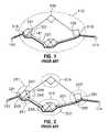
- FIG. 1illustrates known Edge-Based Rerouting (EBR) implementation in the PNNI network
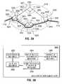
- FIG. 2illustrates known Domain-Based Rerouting (DBR) implementation in the PNNI network
- FIG. 3Aillustrates a global rerouting implementation according to one embodiment of the present invention
- FIG. 3Billustrates a block diagram of a node rerouting management system according to an embodiment of the present invention
- FIG. 3Cillustrates a block diagram of a network rerouting management system according to an embodiment of the present invention
- FIG. 4shows an example structure of rerouting service information elements for supporting a global rerouting protocol
- FIG. 5shows an example structure of rerouting information elements for supporting another global rerouting protocol
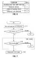
- FIG. 6shows an example of the structure of rerouting cause code information elements
- FIG. 7is a flowchart showing the steps of connection recovery without a rerouting cause code in the embodiment shown in FIG. 3 ;
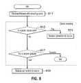
- FIG. 8is a flowchart showing the steps of connection recovery with a rerouting cause code in an embodiment shown in FIG. 3 ;
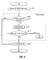
- FIG. 9is a flowchart showing the steps of path optimization in a global basis, in an embodiment shown in FIG. 3 .
- FIG. 1illustrates an example of a known Edge-Based Rerouting (EBR) implementation based on a known ATM Forum EBR specification.
- EBREdge-Based Rerouting
- an EBR rerouting domain 110encompasses the PNNI network including multiple ATM communication nodes.
- the multiple nodesare defined inside the boundary of the rerouting domain 110 , so as that the EBR protocol allows call recovery and path optimization inside the boundary.
- the nodesare interconnected by respective routing links.
- each linkis basically a communication channel or circuit which defines a topological relationship between two nodes connected thereby.
- a source customer premise equipment (CPE) 112originates a call connection with the network at an edge node 116 (“originator”) to another edge node 118 (“terminator”) to establish a call path to a destination CPE 114 through other edge nodes (e.g., nodes 120 and 122 ).
- edge node 116edge node 116
- terminaledge node 118
- other edge nodese.g., nodes 120 and 122
- Each of the nodesincludes a connection admission control (CAC) component.
- the CAC componentis defined as a set of actions taken by the network during a call setup or call re-negotiation phase: i.e., establishing a connection between the source CPE 112 and the destination CPE 114 .
- the CAC componentreceives a number of input parameters, which are a route selection, a traffic descriptor (e.g., Peak Cell Rate (PCR), Sustainable Cell Rate (SCR), Maximum Burst Size (MBS)), link capacity, allocated capacity, and quality of service requirements (e.g., ATM Quality of Service (QoS)), among others.
- PCRPeak Cell Rate
- SCRSustainable Cell Rate
- MCSMaximum Burst Size
- link capacitye.g., allocated capacity
- quality of service requirementse.g., ATM Quality of Service (QoS)
- CAC component of the nodeFor route selection and to determine whether a connection request made by the CPE 12 can be accepted or should be rejected.
- release messagesare sent to the neighbor edge nodes which in turn attempt to re-route the failed connections by calculating new routes with enough capacity/QoS.
- connection recovery protocol and the rerouting methodis performed in the network defined by the EBR rerouting domain 110 .
- the edge nodes 116 , 118 and 120behave as a “rerouting node”, “rendezvous node” and a “transit node” of the EBR rerouting domain 110 , respectively, in accordance with the EBR protocol.
- a call path between the source CPE 112 and the destination CPE 114is established through the nodes 116 , 120 , 122 and 118 with intermediate nodes, as shown by the thickest line. Once established, this call path is an existing path.
- the EBR implementationdefines one rerouting domain 110 from a designated transit list (DTL) originator to a DTL terminator (end-to-end). Therefore, the EBR implementation only supports one rerouting domain that includes the entire PNNI network.
- the established call path(the existing path) may be required to be switched to another call path (i.e., rerouting through a replacement path) for events associated with the established path.
- the eventsare, for example, connection recovery from a link failure and switching to a desirable connection path, the rerouting.
- a pathin an occurrence of a failure of a link 141 interconnecting the nodes 120 and 122 , a path may be switched to a replacement path between the nodes 116 and 118 through nodes 131 , 133 and 135 .
- the existing pathmay be switched to the replacement path.
- the connection recovery and path optimization timesincrease with the size of the network. As the network size increases so does the use of the network resources for connection recovery and path optimization.
- DBRDomain-Based Rerouting
- the Domain-Based Rerouting (DBR) protocolis a standard based protocol, which uses standardized information elements (IEs).
- IEsinformation elements
- a concept in the DBR protocolis based on multiple DBR rerouting domains.
- the major difference between the DBR and EBR protocolsis that in the DBR protocol, a connection registered with the rerouting protocol may traverse multiple DBR rerouting domains before reaching the DTL terminator, as shown in FIG. 2 wherein the PNNI network includes multiple DBR rerouting domains.
- the PNNI networkis defined by four DBR rerouting domains as example.
- Each of the DBR rerouting (local) domains 211 , 213 , 215 and 217is defined by multiple DBR domain nodes therein.
- Each of the DBR rerouting domains 211 , 213 , 215 and 217manages the rerouting functionality (of connection recovery and path optimization) within that DBR domain.
- Each connection segment within a DBR domainbehaves as an independent connection.
- the DBR domainis not tied to the PNNI topology.
- Multiple DBR rerouting domainsmay exist inside a single PNNI peer group.
- a DBR rerouting domainmay include multiple PNNI peer groups.
- the policies of where to define the DBR rerouting domain boundariesare under the control of a network operator.
- Each DBR domain node inside a DBR rerouting domainis interconnected to other nodes in that DBR domain by more than one link. Thus, multiple paths exist to each DBR domain edge node. This ensures an adequate diversity of routes for connection recovery and path optimization.
- DBR domainsmay be defined to maximize visibility of the physical PNNI (H-PNNI) topology to each potential local rerouting node. In this way the local rerouting node makes better route selections.
- H-PNNIphysical PNNI
- the DBR protocoladds a new characteristic to a PNNI link, which is the DBR domain link type. This characteristic identifies whether the neighbor node is part of the same DBR domain or not. If the link is an “intra-domain link” then the PNNI neighbor is part of the same DBR domain. If the link is an “inter-domain link” then the PNNI neighbor is part of another DBR domain. Thus, with IEs representing inter-domains and intra-domains, the boundaries of the DBR domains are defined.
- the source CPE 112originates a connection at an edge node 221 (“originator”) included in the domain 211 to an edge node 231 (“terminator”) included in the domain 217 to establish a call path to the destination CPE 114 through the nodes of the other domain 213 .
- Each nodeincludes a CAC component as mentioned in relation to FIG. 1 .
- the time and use of network resources for connection recovery or path optimizationare smaller inside a DBR rerouting domain than inside an end-to-end (single) domain, because the number of nodes involved in the procedures are smaller.
- connection recovery and path optimizationare based on local topology visible from the rerouting node allowing a better route selection.
- the existing pathis, for example, a path (shown by the thickest line) between the node 221 of the DBR domain 211 and the node 231 of the DBR domain 217 through nodes of the other domain 213 .
- the nodes 221 of the domain 211 , the node 233 of the domain 213 and the node 235 of the domain 217are “rerouting nodes” and the node 245 of the domain 211 , the node 237 of the domain 213 and the node 231 of the domain 217 are “rendezvous nodes”.
- the rerouting and rendezvous nodesperform their functions in accordance with the DBR protocol.
- the rerouting operation in one domainis independent from other domains.
- Events associated with the existing path to rerouteare, for example, connection recovery from a link failure and path optimization.
- a pathmay be switched to a replacement path between the nodes 243 and 245 including a section path through nodes 247 , 249 and 245 in that DBR domain 211 .
- the existing pathmay be switched to the replacement path.
- the present inventionprovides “global” rerouting in connection-oriented communication networks.
- signaling messages for call setupare populated with new definitions of information elements (IEs) that carry information pertaining to requested global rerouting services origination and termination call points and to negotiated local rerouting services.
- IEsinformation elements
- the new IE definitionis created in a way that is compatible with information (potentially) present in call setup messages that pertains to request local rerouting services.
- Call control for processing of call setup, connect and release messagesis defined to differentiate between local and global rerouting services and support both.
- Solution definitions for the global reroutingare created in a way that allows both local and global rerouting services to be enabled simultaneously, thereby offering double fault protection and other solutions to problems described earlier regarding the EBR and DBR protocols.
- This featureintroduces the concept of a global rerouting domain.
- the global reroutingovercomes the disadvantages of the above-mentioned rerouting in the multiple local domains.
- the global rerouting protocolis not standardized.
- FIG. 3Aillustrates global rerouting implementation according to one embodiment of the present invention.
- the entire PNNI networkis defined as a single rerouting domain wherein the interconnected nodes are included.
- the single domainis further defined as multiple divided domains (e.g., four divided domains). Each of the divided domains includes multiple interconnected nodes.
- the single rerouting domainis referred to as a “global” rerouting domain 310 and the four divided domains are referred to as “local” rerouting domains 321 , 323 , 325 and 327 .
- the global rerouting domain 310encapsulates all of the local rerouting domains 321 , 323 , 325 and 327 .
- Each of the local domains 321 , 323 , 325 and 327is defined by multiple nodes.
- the global rerouting protocol implemented in the PNNI network shown in FIG. 3Ais an added extension of the DBR protocol.
- the global rerouting protocolis advantageous over the local rerouting protocol with the above-mentioned DBR protocol, because in the former protocol, all the local inter-domain links are protected and the latter protocol, the inter-domain links are not protected.
- global connection recovery and global path optimizationcan be performed.
- the DTL originator and the DTL terminatormust subscribe to the global rerouting.
- the rerouting domain 321includes interconnected nodes 322 , 324 , 326 , 328 and 330 .
- the rerouting domain 323includes interconnected nodes 332 , 334 , 336 , 338 , 340 and 342 .
- the rerouting domain 325includes interconnected nodes 344 , 346 , 348 and 350 .
- the rerouting domain 327includes interconnected node 352 , 354 , 356 and 358 .
- the nodes of the domainsare interconnected to the nodes of the other domains through respective links.
- Each nodeincludes a CAC component as mentioned in relation to FIG. 1 and it further performs functions for the global and local domain node.
- Each of the edge nodeshas software of performing the functions of the PNNI interface to a CPE and each edge node is capable of being accessed by a CPE connected thereto.
- the PNNI interfaceis may be a hardware module running the PNNI protocol.
- the nodehas multiple PNNI interfaces.
- One PNNI interfaceis connected to another PNNI interface through a physical medium.
- the sums of the entire PNNI interfacescreate the PNNI network, so that the network performs functions and includes mechanisms to achieve global rerouting.
- the mechanismsmay include a call path connection system for establishing a call path and a reroute/connection control systems for establishing a replacement path, a generator for generating a rerouting request and a determination systems for determining a new call path, among others. Specific description of the various components of the systems of the present invention is described on conjunction with FIGS. 3B and 3C .
- the source CPE 112is connected to the node 322 and the destination CPE 114 is connected to the node 346 . It is supposed that the source CPE 112 (the calling party) originates a connection to establish a call path to the destination CPE 114 (the called party) through the nodes of the rerouting domains.
- the source CPE 112accesses the node 322 (“originator”) included in the rerouting domain 321 and the destination CPE 114 accesses the node 346 (“terminator”) included in the rerouting domain 325 .
- the role of any particular node as a rerouting node or rendezvous nodeis determined by the context of the connection.
- a nodeis said to be a local rerouting node what is meant is that it is playing that role for a particular connection (or set of connections), for other connections the same node could be a global rendezvous node.
- the nodehas no rerouting services role. Since node role terms will be used, it is important to understand that the role is specific to each connection.
- the existing pathonce established, is a call path (shown by a bold line) between the node 322 of the domain 321 and the node 342 of the domain 325 through nodes of the other domain 323 .
- the node 322 , 332 and 344are the furthest downstream nodes in the respective rerouting domains 321 , 323 and 325 , and the nodes 326 , 338 and 346 are the furthest upstream nodes in the respective rerouting domains.
- the nodes 322 , 332 and 344behave as “local rerouting nodes” and the nodes 326 , 338 and 346 behave as “local rendezvous nodes”.
- the node 322 of the domain 321is the furthest downstream node in the entire path
- the node 346 of the domain 325is the furthest upstream node in the entire path.
- the nodes 322 and 346perform double functions for the local rerouting domain 321 and the single global domain 310 and the nodes 322 and 346 behave as a “local/global rerouting node” and a “local/global rendezvous node” node, respectively.
- a link 361 between the domains 321 and 323 , a link 363 between the domains 323 and 325 , a link 365 between the domains 325 and 327 , and a link 367 between the domains 327 and 321are referred to “inter-domain links”.
- the links between the two nodes inside a single local rerouting domainare referred to “intra-domain links”.
- the behavior of the nodes of the local rerouting domains in the network shown in FIG. 3Aare different from the local domain nodes in compliance with the DBR and EBR protocols mentioned above in relation to FIGS. 1 and 2 .
- the CAC components of the local domain nodesare modified or further include additional functions to be in compliance with the global rerouting protocol and thus, the PNNI network defined by the global rerouting domain 310 shown in FIG. 3 to support the global rerouting protocol.
- the modified nodeshandle new information transported in DBR relevant IEs (such as the Rerouting Services IE) pertaining to global rerouting information.
- This feature of the global reroutingintroduces the concept of local domain identifier, which is used to determine the local rerouting link type.
- the local domain identifieris advertised on each PNNI interface.
- the local domain boundariesare defined using the local domain identifiers.
- Each of the local rerouting domains 321 , 323 , 325 and 327has a unique identifier which is known by each node in the local domain and is advertised on all their PNNI links.
- a system capabilities information group (IG) containing the domain identifieris added to advertise the local domain identifier.
- Each nodecompares the local domain identifier of its PNNI neighboring node with its own local domain identifier to determine the local domain link type. If the neighboring local domain identifier is identical to the local domain identifier of the node, then the link is an intra-domain link.
- the linkis an inter-domain link. If the neighbor does not advertise any local domain identifier, (i.e., the neighbor does not support that functionality) then the link is an intra-domain link. If the neighbor's local domain identifier is 0, then the link is an intra-domain link, regardless of the node's own local domain identifier. If the node's own local domain identifier is 0, then all the links are intra-domain links, regardless of each neighbor's local domain identifier.
- Route calculations for connections undergoing connection recovery or path optimizationare done according to the existing PNNI route calculation algorithm. Route calculation is thus based on and limited to the visible PNNI topology of the rerouting node. Due to the limited view of the PNNI topology from the rerouting node support of the cumulative administrative weight (CAW) is introduced by this feature. This allows path optimization to determine whether a new path is truly better than the incumbent path based on comparison of CAW values of the new connection segment and the incumbent connection segment. Administrative Weight (AW) is a measure of the cost of a link. Route selection can be optimized based on the optimization metrics of AW and quality of the ATM connection, i.e., Maximum Cell Transfer Delay (CTD) and Cell Delay Variation (CDV). The cumulative metrics for CTD and CDV provide the end-to-end CTD and CDV values for the entire connection. The CAW provides the end-to-end AW value for the entire connection.
- CTDMaximum Cell Transfer Delay
- CDVCell Delay Variation
- the DBR protocolintroduces a new octet group in the “Optional Traffic Attribute” IE (BCS).
- the purpose of this octet groupis to accumulate the actual CAW of the route inside the local domain. If the routing decision is based on AW, the CAW information is used during an optimization to determine if the rerouting segment has a better CAW then the incumbent segment.
- FIG. 3Billustrates a block diagram of a node rerouting management system 380 according to an embodiment of the present invention.
- the view pointis of a node in the network. More particularly, the node system 380 performs rerouting of a connection in a network having interconnected nodes defining a first domain.
- the connectionis defined as a path between an originating node and a terminating node.
- a first domainincludes a plurality of second domains defined by a subset of the interconnected nodes.
- the node system 380includes an event detection mechanism 382 that detects a request (either cause or domain) to reroute a first section of a path of a connection in a reroute domain.
- the reroute domainis defined as one of either the first domain or one of the second domains.
- the node system 380also includes a domain routing determination mechanism 384 that determines a new first section for the path in the reroute domain.
- the mechanism 384includes an information element routing mechanism 385 for determining the new first section for the path in the reroute domains in accordance with the identifier information element (detailed below).
- a connection control/establishment mechanism 386is used to determine and, actually establish a connection, if the connection can be established along the path through the new first section (i.e., the originating node and the terminating node remain connected).
- a fail action (primary-1 st and secondary-2 nd domain) mechanism 388requests rerouting of the connection along a second section of the path in the other of either the first domain or one of the second domains when the connection along the path through the new first section is not established as described above.
- FIG. 3Cillustrates a block diagram of a network rerouting management system 390 according to an embodiment of the present invention.
- the view pointis of the overall network. More particularly, the network system 390 performs rerouting of a connection in a network having a interconnected nodes defining a first domain.
- the connectionis defined as a path between an originating node and a terminating node.
- a first domainincludes a plurality of second domains defined by a subset of the interconnected nodes.
- the network system 390includes an event detection mechanism 392 that detects an event (either cause or domain) in the network (e.g., from IEs described below) indicating a cause to reroute a first section of the path of the connection in a first reroute domain.
- the first reroute domainis one of either the first domain or one of the second domains.
- a primary domain routing determination mechanism 394determines a new first section for the path in the first reroute domain.
- the mechanism 394includes an information element routing mechanism 395 for determining the new first section for the path in the reroute domains in accordance with the identifier information element (detailed below).
- a connection control/establishment mechanism 396determines (and to actually establish) if the connection can be established along the path through the new first section.
- a secondary domain routing determination mechanism 398reroutes the connection along a second section of the path in a second reroute domain when the connection along the path through the new first section is not established.
- the second reroute domainis the other of either the first domain or one of the second domains.
- the node system 380 and the network system 390may be implemented in any conventional computer programming language.
- embodimentsmay be implemented in a procedural programming language (e.g. “C”) or an object oriented language (e.g. “C++”).
- the systems 380 and 390 of the inventionmay be implemented as pre-programmed hardware elements, other related components, or as a combination of hardware and software components.
- Embodimentscan be implemented as a computer program product for use with a computer system.
- Such implementationmay include a series of computer instructions fixed either on a tangible medium, such as a computer readable medium (e.g. a diskette, CD-ROM, ROM, or fixed disk) or transmittable to a computer system, via a modem or other interface device, such as a communications adapter connected to a network over a medium.
- the mediummay be either a tangible medium (e.g. optical or electrical communications lines) or a medium implemented with wireless techniques (e.g. microwave, infrared or other transmission techniques).
- the series of computer instructionsembodies all or part of the functionality previously described herein. Those skilled in the art should appreciate that such computer instructions can be written in a number of programming languages for use with many computer architectures or operating systems.
- Such instructionsmay be stored in any memory device, such as semiconductor, magnetic, optical or other memory devices, and may be transmitted using any communications technology, such as optical, or other transmission technologies.
- a computer program productmay be distributed as a removable medium with accompanying printed or electronic documentation (e.g. shrink wrapped software), preloaded with a computer system (e.g., on system ROM or fixed disk), or distributed from a server over the network (e.g., the Internet or World Wide Web).
- Some embodiments of the inventionmay be implemented as a combination of both software (e.g. a computer program product) and hardware (termed mechanisms). Still other embodiments of the invention may be implemented as entirely hardware, or entirely software (e.g. a computer program product).”
- FIG. 4shows an example of the rerouting service information elements (IEs), which are organized to support the global rerouting and DBR protocols and may be used in implementing the systems and method of the present invention.
- IEsrerouting service information elements
- octets 1 – 8are information for supporting the standard DBR protocol.
- Octets 9 – 12are information for supporting the global rerouting protocol and the information defined therein is additional to the standard DBR IEs.
- the new octet group(octets 9 – 12 ) identifies the global services to be negotiated.
- Octet 1defines rerouting service information element identifier.
- Octet 2defines IE instruction field.
- Octets 3 and 4define a length of the rerouting services.
- Octet 5defines inter-domain services.
- Octet 6defines inter-domain capabilities.
- Octet 7defines intra-domain services.
- Octet 8defines intra-domain capabilities.
- Octet 9defines global rerouting octet identifier. This octet identifies the meaning of the following byte.
- Octet 10defines the global rerouting octet length.
- the byte of the octetidentifies the number of byte of data included in the global rerouting octet groups.
- Octet 11defines global intra-domain services and it includes spare, a soft rerouting class and a hard rerouting class.
- the byteidentifies the global rerouting services requested and negotiated between the global rerouting node and the global rendezvous node.
- Octet 12defines the global intra domain capabilities and it includes spare, asymmetric software, symmetric software and hard rerouting.
- the byteidentifies the global rerouting capability for the global rerouting connection.
- FIG. 5shows an example of the rerouting information elements (IEs), which are organized to support the global rerouting and DBR protocols and may be used in implementing the systems and method of the present invention.
- the IEs shown in FIG. 5include ones for supporting the standard DBR and for supporting the global rerouting protocol.
- the IEs for the global reroutingare additional to the standard DBR IEs.
- octets 1 – 10are information for supporting the standard DBR protocol.
- Octets 11 – 16are information for supporting the global rerouting protocol and the information defined therein is additional to the standard DBR IEs.
- Octets 5 – 16(shown with *) are optional.
- Octet 1defines the rerouting information element identifier.
- Octet 2defines the IE instruction field.
- Octets 3 and 4define the length of the rerouting services.
- Octet 5defines the edge node identifier. It includes octet 5 . 1 for the length of the edge node identifier contents and octets 5 . 2 to 5 . 21 for the edge node AESA.
- AESAis the ATM end system address which is a string of 20 bytes for identifying the ATM node.
- Octet 6defines the endpoint key identifier. It includes octet 6 . 1 for the length of the endpoint key contents and octets 6 . 2 to 6 . 5 for the rerouting control.
- Octet 7defines the rerouting control identifier. It includes octet 7 . 1 for the length of rerouting control contents and octets 7 . 2 to 7 . 4 for the rerouting control.
- Octet 8defines PNNI Cumulative Forward Maximum Cell Transfer Delay identifier. It includes octet 8 . 1 for the length of the maximum CTD contents and octets 8 . 2 to 8 . 4 for the Cumulative Forward Maximum Cell Transfer Delay value.
- Octet 9defines the Cumulative Forward Peak-to-Peak Cell Delay variation identifier. It includes octet 9 . 1 for the length of the Cumulative Forward Peak-to-Peak Cell Delay variation contents and octets 9 . 2 to 9 . 4 for the Cumulative Forward Peak-to-Peak Cell Delay variation value.
- Octet 10defines the Cumulative Backward Peak-to-Peak Cell Delay variation identifier. It includes octet 10 . 1 for the length of the Cumulative Backward Peak-to-Peak Cell Delay variation contents and octets 10 . 2 to 10 . 4 for the Cumulative Backward Peak-to-Peak Cell Delay variation value.
- Octet 11defines the global edge node identifier. It includes octet 11 . 1 for the length of global edge node identifier contents and octets 11 . 2 to 11 . 4 for the global edge node AESA.
- Octet 12defines the global endpoint key identifier. It includes octet 12 . 1 for the length of the global endpoint key contents and octets 12 . 2 to 12 . 5 for the global endpoint key.
- Octet 13defines the global rerouting control identifier. It includes octet 13 . 1 for the length of the global rerouting control contents and octets 13 . 2 to 13 . 4 for the global rerouting control information.
- Octet 14defines the global PNNI Cumulative Forward Maximum Cell Transfer Delay identifier. It includes octet 14 . 1 for the length of the global maximum CTD contents and octets 14 . 2 to 14 . 4 for the global Cumulative Forward Maximum Cell Transfer Delay value.
- Octet 15defines the global Cumulative Forward Peak-to-Peak Cell Delay variation identifier. It includes octet 15 . 1 for the length of the global Cumulative Forward Peak-to-Peak Cell Delay variation contents and octets 15 . 2 to 15 . 4 for the global cumulative Forward Peak-to-Peak Cell Delay variation value.
- Octet 16defines the global Cumulative Backward Peak-to-Peak Cell Delay variation identifier. It includes octet 16 . 1 for the length of the global Cumulative Backward Peak-to-Peak Cell Delay variation contents and octets 16 . 2 to 16 . 4 for the global cumulative Backward Peak-to-Peak Cell Delay variation value.
- the new group of octetsallows negotiation of global rerouting services during call establishment.
- the global Edge Node Identifieris used to identify the global rendezvous node. During a global connection recovery or a global path optimization, the global connection segment terminates at this address.
- the global endpoint key identifieris used to identify the connection at the global rendezvous node.
- the global rerouting control identifieris used to identify the type of switchover mechanism and to identify the instance of a setup message.
- the global PNNI Cumulative Forward Maximum Cell Delay Transfer, the global Cumulative Forward Peak-to-Peak Cell Delay variation and the global Cumulative Backward Peak-to-Peak Cell Delay variationare used to guaranty the quality of services during the global connection recovery and the global path optimization
- FIG. 6shows an example of the rerouting cause code information elements (IEs) and may be used in implementing the systems and method of the present invention.
- IEsrerouting cause code information elements
- octet 1defines a rerouting cause code element identifier (in the form of 0xf2)
- octet 2defines an IE instruction field
- octet 3defines a length of the rerouting service
- octets 4 and 5defines a length of the rerouting service
- octet 5defines a rerouting cause code value.
- two new rerouting cause codesare introduced by the global octet.
- Table Iprovides the meanings of the values of the IEs shown in FIGS. 4–6 .
- connection recoverycaused by a link failure and path optimization for connecting through a desirable path.
- connection recoverycaused by a link failure and path optimization for connecting through a desirable path.
- the followingwill describe local and global connection recovery and global path optimization in accordance with the global rerouting procedure.
- the connectionregisters for local rerouting in all local domains 321 , 323 , 325 and 327 .
- Local path optimization and connection recoveryare affected by a change of local domain boundaries. The local path optimization and connection recovery must be accomplished inside the local domain. If the local boundary is moved such that the local rendezvous node for a connection is moved to another local domain, then local path optimization and local connection recovery will not work as the edge of the local domain will be reached by the rerouted connection before the rendezvous node. Therefore, the local domains must be defined to perform the rerouting for the global, local connection recovery and path optimization.
- FIG. 7shows the steps of the connection recovery without a rerouting cause code in the network shown in FIG. 3 .
- the nodee.g., the local rerouting node 332 of the local domain 323
- receives a call release without a rerouting causestep 711
- a connection recovery in the local rerouting domainis attempted (step 713 ). This is done in accordance with the DBR procedure using the rerouting services IEs and rerouting IEs (the DBR octets) shown in FIGS. 4 and 5 as a specific implementation example.
- the connection pathis switched from the existing path to a replacement path.
- the failed link(e.g., the link between the nodes 334 and 336 of the local domain 323 ) is not part of the replacement path in that local domain (e.g., through the nodes 332 , 342 , 340 and 338 in that local domain 323 ), resulting in the call path being rerouted and the procedure by the node becomes idle.
- step 713if the local recovery attempt is failed, a connection recovery in a global basis is triggered, so that the global connection recovery is attempted (step 715 ). Even though the node 332 behaves as a local rerouting node, it does not behave as a global rerouting node.
- the call releaseis sent to the source node (i.e., the neighbor domain 321 in the downstream direction) (step 717 ).
- the call releasereaches the node 322 of the local domain 321 , if the node 322 has registered for the global connection recovery, then release message is filtered and the global recovery is attempted (step 715 ).
- the global/local rerouting domain 322initiates the global connection recovery.
- the global reroutingis done in accordance with the global rerouting procedure using the rerouting services IEs and rerouting IEs (the global octets) shown in FIGS. 4 and 5 .
- the existing pathis replaced with a new path.
- the new global connection QoSmust meet the current QoS connection of the global connection in the existing path.
- the local domains 321 , 323 and 325are independent; it is possible that multiple local connection recoveries in those domains can take place simultaneously. If a local connection recovery in any of the local domains does not restore the connection (“fail” at step 713 ), the global connection recovery will be triggered (move on to step 715 ).
- the releaseis inside the local rerouting domain 321 wherein the global rerouting node 322 is included. Then, a connection recovery is attempted in the local rerouting domain 321 (step 713 ) and if failed, the failure is outside the domain 321 , that is, the failure is inside or outside the global domain 310 . A global connection recovery is attempted (step 715 ). If the connection recovery is failed both locally and globally, the failure is outside the global domain 310 and it is unable to recover the call connection, resulting in release to the source (step 717 ).
- the global connection recoveryis only possible, in a case where during the negotiation of the original connection the global recovery has been negotiated.
- a hard rerouteis enabled based on the global intra-domain capabilities byte (see FIG. 4 ).
- a new connectionis attempted from the global rerouting node 322 to the global rendezvous node 346 .
- the global rendezvous nodeidentifies inside the rerouting IE (the global Edge Node Identifier (octet 11 ) and the global Endpoint key identifier (octet 12 ) shown in FIG. 5 ). Only the global rerouting parameters are used from the call establishment.
- the global connection segmentswitches this data path to the global rerouting path.
- each local domainnegotiates a new set of local rerouting parameters.
- FIG. 8shows the steps of the connection recovery with a rerouting cause code in the network shown in FIG. 3 .
- the global rerouting node 322receives a release message from the calling party (i.e., the source CPE 112 ) (step 811 ) and a rerouting cause code included in the call release is determined if the release message is a global cause code or not (step 813 ).
- the local rerouting cause code's valuesare defined as shown in Table I.
- the codeis a global cause code
- the connectionis released to the source node (the code's value is shown in Table I (step 815 )).
- a connection recovery in a global basisis attempted (step 817 ).
- the global connection recoveryis done in accordance with the global rerouting which is initiated by the global/local domain node 322 . If the attempt is successful (the code's value as shown in Table I), the failed link (e.g., the link 363 ) will not be part of the global replacement path, which is a path through the links 367 and 365 being interconnected by the other local domain 327 . Then, the procedure becomes idle. If the attempt at step 817 fails (the code's value as shown in Table I), the failure will be outside the global domain 310 and the connection is released to the source (step 819 ).
- the global reroutingintroduces the double fault protection capability of local and global procedures. If a failure occurs inside a local rerouting domain, then the local connection recovery is attempted. If a failure occurs outside a local rerouting domain, then the global connection recovery is attempted. To be a valid connection segment, the new connection segment must meet the negotiated QoS constraints of the connection segment.
- Path optimizationcan be either local or global.
- Global path optimizationcan only be triggered by the global rerouting node (i.e., the node 322 as shown in FIG. 3 ).
- the global new connectionmust respect the original global QoS of the connection. If the global path optimization is not successful and the local path optimization is subscribed, then the local path optimization is attempted.
- the local path optimizationis triggered by the local rerouting node (e.g., the node 332 for the local rerouting domain; the node 344 for the local rerouting domain 325 ).
- the local connection segmentmust preserve the original QoS of the local connection segment.
- each local domainis independent, multiple local path optimizations (e.g., in the local rerouting domains 323 and 325 ) can occur simultaneously. Additionally, the global path optimization may occur simultaneously with one or more local path optimizations. The global path optimization takes precedence over any local path optimizations.
- FIG. 9shows the steps of path optimization in a global basis in the network shown in FIG. 3 .
- the nodereceives an OPTIMIZATION command (step 911 ). It is determined whether the received command is for a global optimization negotiation (step 913 ). In a case of the command being for the global optimization negotiation, the path optimization is attempted in a global basis (step 915 ). If the global path optimization is successful (positive at step 917 ), the procedure will become idle. If the attempt is not successful, the path optimization will be attempted in a local basis (step 919 ) and then, the procedure becomes idle. During the global optimization, the local rerouting nodes 332 and 344 and the local rendezvous nodes 326 and 338 are renegotiated and will align with the new local domain boundaries.
- the global path optimizationis first attempted (step 915 ). In a case of an unsuccessful global path optimization (step 917 ), the local path optimization is attempted (step 919 ). If the node is a local rerouting node and the connection negotiates the service for “global and local path optimization”, then only local optimization is attempted (step 919 ). If the node is a global rerouting node and the connection negotiates the service of “global path optimization only”, then the only global path optimization is attempted (step 917 ). If the node is a local rerouting node and the connection negotiates the service of global optimization, then no action is taken.
- the global path optimization(step 915 ) is only possible in a case where during the negotiation of the original connection, the global path optimization has been negotiated (positive determination at step 913 ).
- Asymmetrical soft reroutingis enabled in the Global intra-domain capabilities byte shown in FIG. 4 (octet 12 ).
- a global path optimization(step 917 ) a new connection is attempted from the global rerouting node 322 to the global rendezvous node 346 (the global rendezvous node is identified by the rerouting IE (the global Edge Node Identifier (octet 11 ) and the global Endpoint key identifier (octet 12 ) shown in FIG. 5 ).
- the QoS of the global connection segmentis identified by the rerouting IE (the global Forward Maximum CTD (octet 14 ) and/or global Forward Peak-to-Peak CDV (octet 15 ) and/or the global Backward Peak-to-Peak CDV (octet 16 ) shown in FIG. 5 ).
- the rerouting IEthe global Forward Maximum CTD (octet 14 ) and/or global Forward Peak-to-Peak CDV (octet 15 ) and/or the global Backward Peak-to-Peak CDV (octet 16 ) shown in FIG. 5 ).
- the global connection segmentwill switch the data (call) path to the global rerouting path (i.e., a replacement path).
- the domainsnegotiate a new set of local rerouting parameters with each other.
- the global rerouting nodeis then releasing the old global path with a rerouting cause code set to 0x14 (Table I, global rerouting operation successful).
- the path optimizationcan be invoked either automatically depending on time of day or manually through an operator command. Automatic path optimization is performed on the entire module. Manually invoked path optimization can be performed on the entire module, a single interface, or a single connection.
- each rerouting servicewill attempt to complete independently. Specifically, the local connection recovery on the local rerouting node will complete unless interrupted by a release of the connection from the global rerouting node, which could be a result of a successfully completed global path optimization.
- the defined single rerouting domainoperates as a global rerouting domain and each divided rerouting domain operates as a local domain.
- the first and second divided domains along the established call pathare the furthest downstream and upstream domains, respectively.
- the furthest downstream and upstream nodes in each of the local domainbehave local rerouting and rendezvous nodes, respectively.
- the rerouting node of the first divided (local) domain and the rendezvous node of the second divided (local) domainbehave as global rerouting and rendezvous nodes, respectively.
- the step of determining a new call pathis performed by the local rerouting and rendezvous nodes of the local domain and the global rerouting and rendezvous nodes.
- the step of generating a rerouting requestcomprises the step of providing the identifier IE associated with nodes inside and outside one local domain, so that the new set of nodes connected in the new call path are inside the global rerouting domain.
- the step of determining a new call pathmay comprise the step of establishing the new call path connecting the new set of nodes between the rerouting and rendezvous nodes of different local domains.
- the event associated with the established connection between the nodesmay be a link failure.
- the step of generating a rerouting requestmay comprise the step of providing a connection recovery request.
- the method for providing a rerouting connectionmay comprise the step providing IEs in accordance with the Domain-Based Rerouting (DBR) standards of the Private Network-Network Interface (PNNI) network.
- DBRDomain-Based Rerouting
- PNNIPrivate Network-Network Interface
- the network of the single rerouting domainis defined by multiple divided domains. The boundaries of the divided domains are defined with reference to part of the DBR IEs.
- unique IEs associating with rerouting and rendezvous nodes of each of the divided domainare different from the DBR IEs.
- a new call path connecting a new set of nodesis determined in accordance with the IEs associating with rerouting and rendezvous nodes of the divided domains.
- the new call path connecting the new set of nodesis determined in accordance with the determined new call path.
- the new call pathincludes segment replaced paths inside the divided domain or between the divided domains.
- the rerouting methodis capable of connection recovery and path optimization outside of any rerouting domains, i.e., global rerouting. It offers double fault recovery: 1) within the rerouting domain as covered by DBR; and 2) outside of the domains or when the initial fault recovery within the domain has failed. It also offers maximum path optimization by first attempting path optimization across all domains and upon failure an optimization within the rerouting domain. This increases the economy of network resource and bandwidth utilization, since path optimization within a rerouting domain not does take into account paths outside of its domain.
- the rerouting methoddefines a second connection recovery across all domains thereby offering double fault protection.
- the rerouting methodprotects such resources and defines a connection recovery as a result thereby offering single fault protection for resources that were not protected previously.
- the rerouting methodconsiders network resources both inside and outside of the divided domains in order to maximize the efficiency of network resource utilization.
- the determination mechanisms 384(of FIG. 3B , and 394 , 398 of FIG. 3C ) comprises an intra-domain call manage mechanism and an inter-domain call manage mechanism.
- the intra-domain call manage mechanismestablishes the replacement path connecting the new set of nodes inside one divided domain with the rerouting and rendezvous nodes in that divided domain.
- the inter-domain call manage mechanismestablishes the replacement path connecting the new set of nodes between the divided domain with the rerouting node of one divided domain and the rendezvous nodes of the other divided domain.
- the event detection mechanism 382 / 392may comprise an information provider for providing cause for the event associated with the event.
- the causeresults in rerouting of connection recovery or path optimization, so that the determination mechanism performs the rerouting accordingly.
- the reroute mechanismmay further comprise an information provider for providing information identifying inter-domain or intra-domain. The determination mechanism performs the rerouting inside one divided domain or between the divided domains.
- connection-oriented networkis a single rerouting domain to enable the connection recovery service and the path optimization in the entire network to be carried out in a large scale.
- the systems and methods of the present inventionare able to offer a significant value added connection service.
- the particular implementation of the present inventionis applied to ATM, but, in general, the present invention is transferable to all other connection-oriented technologies.
- Implementation of the present inventionenables to offer a service to a customer that enables double fault protection for network resources through local and global connection recovery. It also increases the efficiency and economy of network resource utilization through the introduction of global path optimization. This type of service is extremely attractive in carrier type networks where network robustness is highly important as well as efficiency and economy of network resource utilization to bring down operational costs.
- the rerouting method by the global domain for connection recovery and path optimizationcan be applied to the MPLS networks and TDM and Optical networks.
Landscapes
- Engineering & Computer Science (AREA)
- Computer Networks & Wireless Communication (AREA)
- Signal Processing (AREA)
- Environmental & Geological Engineering (AREA)
- Data Exchanges In Wide-Area Networks (AREA)
Abstract
Description
| TABLE I | ||
| Rerouting | Value | Description |
| DBR | 0×01 | release receive from outside local rerouting domain |
| DBR | 0×02 | failed to recover the connection using local domain |
| based rerouting | ||
| DBR | 0×03 | Unrecognized endpoint key for rerouting |
| DBR | 0×04 | rerouting operation completed |
| DBR | 0×05 | old incarnation number |
| DBR | 0×06 | rerouting operation already in progress |
| DBR | 0×07 | violation of rerouting domain boundary |
| DBR | 0×08 | Unsupported switchover behavior |
| Global | 0×12 | failed to recover the connection using global rerouting |
| protocol | ||
| Global | 0×14 | global rerouting operation successful |
Claims (49)
Priority Applications (1)
| Application Number | Priority Date | Filing Date | Title |
|---|---|---|---|
| US10/192,498US7180866B1 (en) | 2002-07-11 | 2002-07-11 | Rerouting in connection-oriented communication networks and communication systems |
Applications Claiming Priority (1)
| Application Number | Priority Date | Filing Date | Title |
|---|---|---|---|
| US10/192,498US7180866B1 (en) | 2002-07-11 | 2002-07-11 | Rerouting in connection-oriented communication networks and communication systems |
Publications (1)
| Publication Number | Publication Date |
|---|---|
| US7180866B1true US7180866B1 (en) | 2007-02-20 |
Family
ID=37745029
Family Applications (1)
| Application Number | Title | Priority Date | Filing Date |
|---|---|---|---|
| US10/192,498Expired - Fee RelatedUS7180866B1 (en) | 2002-07-11 | 2002-07-11 | Rerouting in connection-oriented communication networks and communication systems |
Country Status (1)
| Country | Link |
|---|---|
| US (1) | US7180866B1 (en) |
Cited By (103)
| Publication number | Priority date | Publication date | Assignee | Title |
|---|---|---|---|---|
| US20040151181A1 (en)* | 2003-02-04 | 2004-08-05 | Chu Thomas P. | Methods and systems for providing MPLS-based layer-2 virtual private network services |
| US20040190456A1 (en)* | 2003-01-31 | 2004-09-30 | Robert Haas | Data path-based service deployment in hierarchical networks |
| US20050053014A1 (en)* | 2003-07-25 | 2005-03-10 | Kanchei Loa | System and method of implementing contacts of small worlds in packet communication networks |
| US20050083834A1 (en)* | 2003-10-17 | 2005-04-21 | Microsoft Corporation | Method for providing guaranteed distributed failure notification |
| US20050160171A1 (en)* | 2003-12-22 | 2005-07-21 | Nortel Networks Limited | Traffic engineering and bandwidth management of bundled links |
| US20050273517A1 (en)* | 2004-05-21 | 2005-12-08 | Bea Systems, Inc. | Service oriented architecture with credential management |
| US20050273520A1 (en)* | 2004-05-21 | 2005-12-08 | Bea Systems, Inc. | Service oriented architecture with file transport protocol |
| US20050278335A1 (en)* | 2004-05-21 | 2005-12-15 | Bea Systems, Inc. | Service oriented architecture with alerts |
| US20060005063A1 (en)* | 2004-05-21 | 2006-01-05 | Bea Systems, Inc. | Error handling for a service oriented architecture |
| US20060031481A1 (en)* | 2004-05-21 | 2006-02-09 | Bea Systems, Inc. | Service oriented architecture with monitoring |
| US20060080419A1 (en)* | 2004-05-21 | 2006-04-13 | Bea Systems, Inc. | Reliable updating for a service oriented architecture |
| US20060164983A1 (en)* | 2002-08-14 | 2006-07-27 | Michael Menth | Access control for packet-oriented networks |
| US20060221813A1 (en)* | 2005-04-04 | 2006-10-05 | Scudder John G | Loop prevention techniques using encapsulation manipulation of IP/MPLS field |
| US20070058620A1 (en)* | 2005-08-31 | 2007-03-15 | Mcdata Corporation | Management of a switch fabric through functionality conservation |
| US20070217340A1 (en)* | 2006-03-17 | 2007-09-20 | Fujitsu Limited | QoS information notification method, communication apparatus and inter-domain signaling apparatus for transmitting QoS information over a multi-domain network |
| US20070217419A1 (en)* | 2006-03-14 | 2007-09-20 | Jean-Philippe Vasseur | Technique for efficiently routing IP traffic on CE-CE paths across a provider network |
| US20070223681A1 (en)* | 2006-03-22 | 2007-09-27 | Walden James M | Protocols for connecting intelligent service modules in a storage area network |
| US20070258380A1 (en)* | 2006-05-02 | 2007-11-08 | Mcdata Corporation | Fault detection, isolation and recovery for a switch system of a computer network |
| US20070258443A1 (en)* | 2006-05-02 | 2007-11-08 | Mcdata Corporation | Switch hardware and architecture for a computer network |
| US20080002711A1 (en)* | 2006-06-30 | 2008-01-03 | Bugenhagen Michael K | System and method for access state based service options |
| US20080002716A1 (en)* | 2006-06-30 | 2008-01-03 | Wiley William L | System and method for selecting network egress |
| US20080002670A1 (en)* | 2006-06-30 | 2008-01-03 | Bugenhagen Michael K | System and method for adjusting code speed in a transmission path during call set-up due to reduced transmission performance |
| US20080049927A1 (en)* | 2006-08-22 | 2008-02-28 | Wiley William L | System and method for establishing a call being received by a trunk on a packet network |
| US20080049753A1 (en)* | 2006-08-22 | 2008-02-28 | Heinze John M | System and method for load balancing network resources using a connection admission control engine |
| US20080049637A1 (en)* | 2006-08-22 | 2008-02-28 | Morrill Robert J | System and method for establishing calls over a call path having best path metrics |
| US20080049751A1 (en)* | 2006-08-23 | 2008-02-28 | Cisco Technology, Inc. | Method and system for computing as-disjoint inter-as traffic engineering-label switched paths (TE-LSPs) |
| US20080049769A1 (en)* | 2006-08-22 | 2008-02-28 | Bugenhagen Michael K | Application-specific integrated circuit for monitoring and optimizing interlayer network performance |
| US20080049631A1 (en)* | 2006-08-22 | 2008-02-28 | Morrill Robert J | System and method for monitoring interlayer devices and optimizing network performance |
| US20080049626A1 (en)* | 2006-08-22 | 2008-02-28 | Bugenhagen Michael K | System and method for communicating network performance information over a packet network |
| US20080049777A1 (en)* | 2006-08-22 | 2008-02-28 | Morrill Robert J | System and method for using distributed network performance information tables to manage network communications |
| US20080049638A1 (en)* | 2006-08-22 | 2008-02-28 | Ray Amar N | System and method for monitoring and optimizing network performance with user datagram protocol network performance information packets |
| US20080052393A1 (en)* | 2006-08-22 | 2008-02-28 | Mcnaughton James L | System and method for remotely controlling network operators |
| US20080049748A1 (en)* | 2006-08-22 | 2008-02-28 | Bugenhagen Michael K | System and method for routing communications between packet networks based on intercarrier agreements |
| US20080049628A1 (en)* | 2006-08-22 | 2008-02-28 | Bugenhagen Michael K | System and method for modifying connectivity fault management packets |
| US20080052784A1 (en)* | 2006-08-22 | 2008-02-28 | Wiley William L | System and method for restricting access to network performance information tables |
| US20080049640A1 (en)* | 2006-08-22 | 2008-02-28 | Heinz John M | System and method for provisioning resources of a packet network based on collected network performance information |
| US20080049639A1 (en)* | 2006-08-22 | 2008-02-28 | Wiley William L | System and method for managing a service level agreement |
| US20080049745A1 (en)* | 2006-08-22 | 2008-02-28 | Edwards Stephen K | System and method for enabling reciprocal billing for different types of communications over a packet network |
| US20080049650A1 (en)* | 2006-08-22 | 2008-02-28 | Coppage Carl M | System and method for managing radio frequency windows |
| US20080052628A1 (en)* | 2006-08-22 | 2008-02-28 | Bugenhagen Michael K | System and method for displaying a graphical representation of a network to identify nodes and node segments on the network that are not operating normally |
| US20080049747A1 (en)* | 2006-08-22 | 2008-02-28 | Mcnaughton James L | System and method for handling reservation requests with a connection admission control engine |
| US20080052387A1 (en)* | 2006-08-22 | 2008-02-28 | Heinz John M | System and method for tracking application resource usage |
| US20080052394A1 (en)* | 2006-08-22 | 2008-02-28 | Bugenhagen Michael K | System and method for initiating diagnostics on a packet network node |
| US20080049787A1 (en)* | 2006-08-22 | 2008-02-28 | Mcnaughton James L | System and method for controlling network bandwidth with a connection admission control engine |
| US20080095173A1 (en)* | 2006-10-19 | 2008-04-24 | Embarq Holdings Company, Llc | System and method for monitoring the connection of an end-user to a remote network |
| US20080095049A1 (en)* | 2006-10-19 | 2008-04-24 | Embarq Holdings Company, Llc | System and method for establishing a communications session with an end-user based on the state of a network connection |
| US20080167846A1 (en)* | 2006-10-25 | 2008-07-10 | Embarq Holdings Company, Llc | System and method for regulating messages between networks |
| US20080205262A1 (en)* | 2007-02-23 | 2008-08-28 | Motoki Suzuki | Node controller and node system |
| US20080288304A1 (en)* | 2007-05-18 | 2008-11-20 | Bea Systems, Inc. | System and Method for Enabling Decision Activities in a Process Management and Design Environment |
| US7653008B2 (en) | 2004-05-21 | 2010-01-26 | Bea Systems, Inc. | Dynamically configurable service oriented architecture |
| US20100085887A1 (en)* | 2006-08-22 | 2010-04-08 | Embarq Holdings Company, Llc | System and method for adjusting the window size of a tcp packet through network elements |
| US20100106999A1 (en)* | 2007-10-03 | 2010-04-29 | Foundry Networks, Inc. | Techniques for determining local repair paths using cspf |
| US20100208611A1 (en)* | 2007-05-31 | 2010-08-19 | Embarq Holdings Company, Llc | System and method for modifying network traffic |
| US7792019B1 (en)* | 2006-06-22 | 2010-09-07 | Verizon Patent And Licensing Inc. | Call management |
| US20110032821A1 (en)* | 2006-08-22 | 2011-02-10 | Morrill Robert J | System and method for routing data on a packet network |
| US20110252129A1 (en)* | 2010-04-12 | 2011-10-13 | Chung-Ang University Industry-Academy Cooperation | Apparatus and method for registering node and searching for floating internet protocol address using distributed network |
| US8040792B2 (en)* | 2007-08-02 | 2011-10-18 | Foundry Networks, Llc | Techniques for determining local repair connections |
| US20110267979A1 (en)* | 2009-10-07 | 2011-11-03 | Nec Corporation | Communication system control apparatus, control method, and program |
| US8107366B2 (en) | 2006-08-22 | 2012-01-31 | Embarq Holdings Company, LP | System and method for using centralized network performance tables to manage network communications |
| US8185916B2 (en) | 2007-06-28 | 2012-05-22 | Oracle International Corporation | System and method for integrating a business process management system with an enterprise service bus |
| US20120131376A1 (en)* | 2010-11-19 | 2012-05-24 | Alcatel-Lucent | Method and system for cell recovery in telecommunication networks |
| US8213366B2 (en) | 2006-08-22 | 2012-07-03 | Embarq Holdings Company, Llc | System and method for monitoring and optimizing network performance to a wireless device |
| US8274905B2 (en) | 2006-08-22 | 2012-09-25 | Embarq Holdings Company, Llc | System and method for displaying a graph representative of network performance over a time period |
| US20130044587A1 (en)* | 2009-10-30 | 2013-02-21 | Calxeda, Inc. | System and method for high-performance, low-power data center interconnect fabric with addressing and unicast routing |
| US8634302B2 (en) | 2010-07-30 | 2014-01-21 | Alcatel Lucent | Apparatus for multi-cell support in a network |
| US20140105002A1 (en)* | 2005-02-14 | 2014-04-17 | Brixham Solutions Ltd. | Pseudowire protection using a standby pseudowire |
| US8711676B2 (en) | 2007-08-02 | 2014-04-29 | Foundry Networks, Llc | Techniques for determining optimized local repair paths |
| US8717911B2 (en) | 2006-06-30 | 2014-05-06 | Centurylink Intellectual Property Llc | System and method for collecting network performance information |
| US8737417B2 (en) | 2010-11-12 | 2014-05-27 | Alcatel Lucent | Lock-less and zero copy messaging scheme for telecommunication network applications |
| US8750158B2 (en) | 2006-08-22 | 2014-06-10 | Centurylink Intellectual Property Llc | System and method for differentiated billing |
| US8861434B2 (en) | 2010-11-29 | 2014-10-14 | Alcatel Lucent | Method and system for improved multi-cell support on a single modem board |
| US8879391B2 (en) | 2008-04-09 | 2014-11-04 | Centurylink Intellectual Property Llc | System and method for using network derivations to determine path states |
| US20140337668A1 (en)* | 2011-05-06 | 2014-11-13 | Tellabs Operations, Inc. | Method And Apparatus For Coordinating Fault Recovery Techniques Among Domains |
| US9094257B2 (en) | 2006-06-30 | 2015-07-28 | Centurylink Intellectual Property Llc | System and method for selecting a content delivery network |
| US9143841B2 (en) | 2005-09-29 | 2015-09-22 | Brocade Communications Systems, Inc. | Federated management of intelligent service modules |
| US9311269B2 (en) | 2009-10-30 | 2016-04-12 | Iii Holdings 2, Llc | Network proxy for high-performance, low-power data center interconnect fabric |
| US9357482B2 (en) | 2011-07-13 | 2016-05-31 | Alcatel Lucent | Method and system for dynamic power control for base stations |
| US9356859B2 (en) | 2011-08-16 | 2016-05-31 | Brocade Communications Systems, Inc. | Techniques for performing a failover from a protected connection to a backup connection |
| US9465771B2 (en) | 2009-09-24 | 2016-10-11 | Iii Holdings 2, Llc | Server on a chip and node cards comprising one or more of same |
| US9479463B2 (en) | 2009-10-30 | 2016-10-25 | Iii Holdings 2, Llc | System and method for data center security enhancements leveraging managed server SOCs |
| US9509552B2 (en) | 2009-10-30 | 2016-11-29 | Iii Holdings 2, Llc | System and method for data center security enhancements leveraging server SOCs or server fabrics |
| US9585281B2 (en) | 2011-10-28 | 2017-02-28 | Iii Holdings 2, Llc | System and method for flexible storage and networking provisioning in large scalable processor installations |
| US9621361B2 (en) | 2006-08-22 | 2017-04-11 | Centurylink Intellectual Property Llc | Pin-hole firewall for communicating data packets on a packet network |
| US9648102B1 (en) | 2012-12-27 | 2017-05-09 | Iii Holdings 2, Llc | Memcached server functionality in a cluster of data processing nodes |
| US9680770B2 (en) | 2009-10-30 | 2017-06-13 | Iii Holdings 2, Llc | System and method for using a multi-protocol fabric module across a distributed server interconnect fabric |
| US9792249B2 (en) | 2011-10-31 | 2017-10-17 | Iii Holdings 2, Llc | Node card utilizing a same connector to communicate pluralities of signals |
| US9876735B2 (en) | 2009-10-30 | 2018-01-23 | Iii Holdings 2, Llc | Performance and power optimized computer system architectures and methods leveraging power optimized tree fabric interconnect |
| US10140245B2 (en) | 2009-10-30 | 2018-11-27 | Iii Holdings 2, Llc | Memcached server functionality in a cluster of data processing nodes |
| WO2019141211A1 (en)* | 2018-01-17 | 2019-07-25 | 中兴通讯股份有限公司 | Peer-to-peer rerouting method and device |
| CN111131028A (en)* | 2019-10-16 | 2020-05-08 | 河南工程学院 | An Inter-Domain Routing Restoration Method Based on Degree Constrained Minimum Spanning Tree |
| US10877695B2 (en) | 2009-10-30 | 2020-12-29 | Iii Holdings 2, Llc | Memcached server functionality in a cluster of data processing nodes |
| CN114553767A (en)* | 2021-11-04 | 2022-05-27 | 国网浙江省电力有限公司湖州供电公司 | Rerouting technology for survivability of power communication network |
| US11467883B2 (en) | 2004-03-13 | 2022-10-11 | Iii Holdings 12, Llc | Co-allocating a reservation spanning different compute resources types |
| US11496415B2 (en) | 2005-04-07 | 2022-11-08 | Iii Holdings 12, Llc | On-demand access to compute resources |
| US11494235B2 (en) | 2004-11-08 | 2022-11-08 | Iii Holdings 12, Llc | System and method of providing system jobs within a compute environment |
| US11522952B2 (en) | 2007-09-24 | 2022-12-06 | The Research Foundation For The State University Of New York | Automatic clustering for self-organizing grids |
| US11630704B2 (en) | 2004-08-20 | 2023-04-18 | Iii Holdings 12, Llc | System and method for a workload management and scheduling module to manage access to a compute environment according to local and non-local user identity information |
| US11652706B2 (en) | 2004-06-18 | 2023-05-16 | Iii Holdings 12, Llc | System and method for providing dynamic provisioning within a compute environment |
| US11650857B2 (en) | 2006-03-16 | 2023-05-16 | Iii Holdings 12, Llc | System and method for managing a hybrid computer environment |
| US11658916B2 (en) | 2005-03-16 | 2023-05-23 | Iii Holdings 12, Llc | Simple integration of an on-demand compute environment |
| US11720290B2 (en) | 2009-10-30 | 2023-08-08 | Iii Holdings 2, Llc | Memcached server functionality in a cluster of data processing nodes |
| US11960937B2 (en) | 2004-03-13 | 2024-04-16 | Iii Holdings 12, Llc | System and method for an optimizing reservation in time of compute resources based on prioritization function and reservation policy parameter |
| US12120040B2 (en) | 2005-03-16 | 2024-10-15 | Iii Holdings 12, Llc | On-demand compute environment |
Citations (6)
| Publication number | Priority date | Publication date | Assignee | Title |
|---|---|---|---|---|
| US6115753A (en)* | 1997-02-18 | 2000-09-05 | Alcatel | Method for rerouting in hierarchically structured networks |
| US6141325A (en)* | 1996-12-18 | 2000-10-31 | International Business Machines Corporation | Paradigm for enabling interoperability between different subnetworks |
| US6594235B1 (en)* | 1999-04-28 | 2003-07-15 | 3Com Corporation | Method of triggering reroutes in an asynchronous transfer mode network |
| US6690653B1 (en)* | 1998-10-22 | 2004-02-10 | Marconi Communications, Inc. | Split-switch based PNNI hierarchy |
| US6735176B1 (en)* | 1998-03-26 | 2004-05-11 | Nortel Networks Limited | Dynamic bandwidth management and rerouting |
| US20040139150A1 (en)* | 1999-06-01 | 2004-07-15 | Fastforward Networks, Inc. | System for multipoint infrastructure transport in a computer network |
- 2002
- 2002-07-11USUS10/192,498patent/US7180866B1/ennot_activeExpired - Fee Related
Patent Citations (6)
| Publication number | Priority date | Publication date | Assignee | Title |
|---|---|---|---|---|
| US6141325A (en)* | 1996-12-18 | 2000-10-31 | International Business Machines Corporation | Paradigm for enabling interoperability between different subnetworks |
| US6115753A (en)* | 1997-02-18 | 2000-09-05 | Alcatel | Method for rerouting in hierarchically structured networks |
| US6735176B1 (en)* | 1998-03-26 | 2004-05-11 | Nortel Networks Limited | Dynamic bandwidth management and rerouting |
| US6690653B1 (en)* | 1998-10-22 | 2004-02-10 | Marconi Communications, Inc. | Split-switch based PNNI hierarchy |
| US6594235B1 (en)* | 1999-04-28 | 2003-07-15 | 3Com Corporation | Method of triggering reroutes in an asynchronous transfer mode network |
| US20040139150A1 (en)* | 1999-06-01 | 2004-07-15 | Fastforward Networks, Inc. | System for multipoint infrastructure transport in a computer network |
Cited By (237)
| Publication number | Priority date | Publication date | Assignee | Title |
|---|---|---|---|---|
| US20060164983A1 (en)* | 2002-08-14 | 2006-07-27 | Michael Menth | Access control for packet-oriented networks |
| US20100226249A1 (en)* | 2002-08-14 | 2010-09-09 | Nokia Siemens Networks Gmbh & Co. Kg | Access control for packet-oriented networks |
| US20040190456A1 (en)* | 2003-01-31 | 2004-09-30 | Robert Haas | Data path-based service deployment in hierarchical networks |
| US7808896B2 (en)* | 2003-01-31 | 2010-10-05 | International Business Machines Corporation | Data path-based service deployment in hierarchical networks |
| US7872991B2 (en)* | 2003-02-04 | 2011-01-18 | Alcatel-Lucent Usa Inc. | Methods and systems for providing MPLS-based layer-2 virtual private network services |
| US20040151181A1 (en)* | 2003-02-04 | 2004-08-05 | Chu Thomas P. | Methods and systems for providing MPLS-based layer-2 virtual private network services |
| US20050053014A1 (en)* | 2003-07-25 | 2005-03-10 | Kanchei Loa | System and method of implementing contacts of small worlds in packet communication networks |
| US7616632B2 (en)* | 2003-07-25 | 2009-11-10 | Kanchei Loa | System and method of implementing contacts of small worlds in packet communication networks |
| US7551552B2 (en)* | 2003-10-17 | 2009-06-23 | Microsoft Corporation | Method for providing guaranteed distributed failure notification |
| US20050083834A1 (en)* | 2003-10-17 | 2005-04-21 | Microsoft Corporation | Method for providing guaranteed distributed failure notification |
| US8312145B2 (en)* | 2003-12-22 | 2012-11-13 | Rockstar Consortium US L.P. | Traffic engineering and bandwidth management of bundled links |
| US20050160171A1 (en)* | 2003-12-22 | 2005-07-21 | Nortel Networks Limited | Traffic engineering and bandwidth management of bundled links |
| US9130861B2 (en)* | 2003-12-22 | 2015-09-08 | Rpx Clearinghouse Llc | Traffic engineering and bandwidth management of bundled links |
| US8463916B2 (en)* | 2003-12-22 | 2013-06-11 | Rockstar Consortium Us Lp | Traffic engineering and bandwidth management of bundled links |
| US11467883B2 (en) | 2004-03-13 | 2022-10-11 | Iii Holdings 12, Llc | Co-allocating a reservation spanning different compute resources types |
| US12124878B2 (en) | 2004-03-13 | 2024-10-22 | Iii Holdings 12, Llc | System and method for scheduling resources within a compute environment using a scheduler process with reservation mask function |
| US11960937B2 (en) | 2004-03-13 | 2024-04-16 | Iii Holdings 12, Llc | System and method for an optimizing reservation in time of compute resources based on prioritization function and reservation policy parameter |
| US20050278335A1 (en)* | 2004-05-21 | 2005-12-15 | Bea Systems, Inc. | Service oriented architecture with alerts |
| US20050273520A1 (en)* | 2004-05-21 | 2005-12-08 | Bea Systems, Inc. | Service oriented architecture with file transport protocol |
| US20060031481A1 (en)* | 2004-05-21 | 2006-02-09 | Bea Systems, Inc. | Service oriented architecture with monitoring |
| US20050273517A1 (en)* | 2004-05-21 | 2005-12-08 | Bea Systems, Inc. | Service oriented architecture with credential management |
| US20060005063A1 (en)* | 2004-05-21 | 2006-01-05 | Bea Systems, Inc. | Error handling for a service oriented architecture |
| US7653008B2 (en) | 2004-05-21 | 2010-01-26 | Bea Systems, Inc. | Dynamically configurable service oriented architecture |
| US20060080419A1 (en)* | 2004-05-21 | 2006-04-13 | Bea Systems, Inc. | Reliable updating for a service oriented architecture |
| US12009996B2 (en) | 2004-06-18 | 2024-06-11 | Iii Holdings 12, Llc | System and method for providing dynamic provisioning within a compute environment |
| US11652706B2 (en) | 2004-06-18 | 2023-05-16 | Iii Holdings 12, Llc | System and method for providing dynamic provisioning within a compute environment |
| US11630704B2 (en) | 2004-08-20 | 2023-04-18 | Iii Holdings 12, Llc | System and method for a workload management and scheduling module to manage access to a compute environment according to local and non-local user identity information |
| US11886915B2 (en) | 2004-11-08 | 2024-01-30 | Iii Holdings 12, Llc | System and method of providing system jobs within a compute environment |
| US11656907B2 (en) | 2004-11-08 | 2023-05-23 | Iii Holdings 12, Llc | System and method of providing system jobs within a compute environment |
| US11537434B2 (en) | 2004-11-08 | 2022-12-27 | Iii Holdings 12, Llc | System and method of providing system jobs within a compute environment |
| US11537435B2 (en) | 2004-11-08 | 2022-12-27 | Iii Holdings 12, Llc | System and method of providing system jobs within a compute environment |
| US11861404B2 (en) | 2004-11-08 | 2024-01-02 | Iii Holdings 12, Llc | System and method of providing system jobs within a compute environment |
| US12008405B2 (en) | 2004-11-08 | 2024-06-11 | Iii Holdings 12, Llc | System and method of providing system jobs within a compute environment |
| US11494235B2 (en) | 2004-11-08 | 2022-11-08 | Iii Holdings 12, Llc | System and method of providing system jobs within a compute environment |
| US11762694B2 (en) | 2004-11-08 | 2023-09-19 | Iii Holdings 12, Llc | System and method of providing system jobs within a compute environment |
| US11709709B2 (en) | 2004-11-08 | 2023-07-25 | Iii Holdings 12, Llc | System and method of providing system jobs within a compute environment |
| US12039370B2 (en) | 2004-11-08 | 2024-07-16 | Iii Holdings 12, Llc | System and method of providing system jobs within a compute environment |
| US20140105002A1 (en)* | 2005-02-14 | 2014-04-17 | Brixham Solutions Ltd. | Pseudowire protection using a standby pseudowire |
| US9749249B2 (en)* | 2005-02-14 | 2017-08-29 | Brixham Solutions Ltd. | Pseudowire protection using a standby pseudowire |
| US11658916B2 (en) | 2005-03-16 | 2023-05-23 | Iii Holdings 12, Llc | Simple integration of an on-demand compute environment |
| US12120040B2 (en) | 2005-03-16 | 2024-10-15 | Iii Holdings 12, Llc | On-demand compute environment |
| US20090147674A1 (en)* | 2005-04-04 | 2009-06-11 | Cisco Technology, Inc. | Loop prevention techniques using encapsulation manipulation of ip/mpls field |
| US7869345B2 (en) | 2005-04-04 | 2011-01-11 | Cisco Technology, Inc. | Loop prevention techniques using encapsulation manipulation of IP/MPLS field |
| US7477593B2 (en)* | 2005-04-04 | 2009-01-13 | Cisco Technology, Inc. | Loop prevention techniques using encapsulation manipulation of IP/MPLS field |
| US20060221813A1 (en)* | 2005-04-04 | 2006-10-05 | Scudder John G | Loop prevention techniques using encapsulation manipulation of IP/MPLS field |
| US12155582B2 (en) | 2005-04-07 | 2024-11-26 | Iii Holdings 12, Llc | On-demand access to compute resources |
| US11522811B2 (en) | 2005-04-07 | 2022-12-06 | Iii Holdings 12, Llc | On-demand access to compute resources |
| US11533274B2 (en) | 2005-04-07 | 2022-12-20 | Iii Holdings 12, Llc | On-demand access to compute resources |
| US11496415B2 (en) | 2005-04-07 | 2022-11-08 | Iii Holdings 12, Llc | On-demand access to compute resources |
| US11765101B2 (en) | 2005-04-07 | 2023-09-19 | Iii Holdings 12, Llc | On-demand access to compute resources |
| US11831564B2 (en) | 2005-04-07 | 2023-11-28 | Iii Holdings 12, Llc | On-demand access to compute resources |
| US12160371B2 (en) | 2005-04-07 | 2024-12-03 | Iii Holdings 12, Llc | On-demand access to compute resources |
| US20070058620A1 (en)* | 2005-08-31 | 2007-03-15 | Mcdata Corporation | Management of a switch fabric through functionality conservation |
| US10361903B2 (en) | 2005-09-29 | 2019-07-23 | Avago Technologies International Sales Pte. Limited | Federated management of intelligent service modules |
| US9661085B2 (en) | 2005-09-29 | 2017-05-23 | Brocade Communications Systems, Inc. | Federated management of intelligent service modules |
| US9143841B2 (en) | 2005-09-29 | 2015-09-22 | Brocade Communications Systems, Inc. | Federated management of intelligent service modules |
| US7522603B2 (en)* | 2006-03-14 | 2009-04-21 | Cisco Technology, Inc. | Technique for efficiently routing IP traffic on CE-CE paths across a provider network |
| US20070217419A1 (en)* | 2006-03-14 | 2007-09-20 | Jean-Philippe Vasseur | Technique for efficiently routing IP traffic on CE-CE paths across a provider network |
| WO2007106484A3 (en)* | 2006-03-14 | 2009-04-30 | Cisco Tech Inc | Technique for efficiently routing ip traffic on ce-ce paths across a provider network |
| US11650857B2 (en) | 2006-03-16 | 2023-05-16 | Iii Holdings 12, Llc | System and method for managing a hybrid computer environment |
| US20070217340A1 (en)* | 2006-03-17 | 2007-09-20 | Fujitsu Limited | QoS information notification method, communication apparatus and inter-domain signaling apparatus for transmitting QoS information over a multi-domain network |
| US8005090B2 (en)* | 2006-03-17 | 2011-08-23 | Fujitsu Limited | QoS information notification method, communication apparatus and inter-domain signaling apparatus for transmitting QoS information over a multi-domain network |
| US8595352B2 (en) | 2006-03-22 | 2013-11-26 | Brocade Communications Systems, Inc. | Protocols for connecting intelligent service modules in a storage area network |
| US7953866B2 (en) | 2006-03-22 | 2011-05-31 | Mcdata Corporation | Protocols for connecting intelligent service modules in a storage area network |
| US20070223681A1 (en)* | 2006-03-22 | 2007-09-27 | Walden James M | Protocols for connecting intelligent service modules in a storage area network |
| US20070258380A1 (en)* | 2006-05-02 | 2007-11-08 | Mcdata Corporation | Fault detection, isolation and recovery for a switch system of a computer network |
| US20070258443A1 (en)* | 2006-05-02 | 2007-11-08 | Mcdata Corporation | Switch hardware and architecture for a computer network |
| US7792019B1 (en)* | 2006-06-22 | 2010-09-07 | Verizon Patent And Licensing Inc. | Call management |
| US8599682B2 (en) | 2006-06-22 | 2013-12-03 | Verizon Patent And Licensing Inc. | Call management |
| US20100322388A1 (en)* | 2006-06-22 | 2010-12-23 | Verizon Patent And Licensing Inc. | Call management |
| US9094257B2 (en) | 2006-06-30 | 2015-07-28 | Centurylink Intellectual Property Llc | System and method for selecting a content delivery network |
| US8717911B2 (en) | 2006-06-30 | 2014-05-06 | Centurylink Intellectual Property Llc | System and method for collecting network performance information |
| US9154634B2 (en) | 2006-06-30 | 2015-10-06 | Centurylink Intellectual Property Llc | System and method for managing network communications |
| US20080002670A1 (en)* | 2006-06-30 | 2008-01-03 | Bugenhagen Michael K | System and method for adjusting code speed in a transmission path during call set-up due to reduced transmission performance |
| US9749399B2 (en) | 2006-06-30 | 2017-08-29 | Centurylink Intellectual Property Llc | System and method for selecting a content delivery network |
| US9118583B2 (en) | 2006-06-30 | 2015-08-25 | Centurylink Intellectual Property Llc | System and method for re-routing calls |
| US20080002716A1 (en)* | 2006-06-30 | 2008-01-03 | Wiley William L | System and method for selecting network egress |
| US9054915B2 (en) | 2006-06-30 | 2015-06-09 | Centurylink Intellectual Property Llc | System and method for adjusting CODEC speed in a transmission path during call set-up due to reduced transmission performance |
| US8976665B2 (en) | 2006-06-30 | 2015-03-10 | Centurylink Intellectual Property Llc | System and method for re-routing calls |
| US9549004B2 (en) | 2006-06-30 | 2017-01-17 | Centurylink Intellectual Property Llc | System and method for re-routing calls |
| US8184549B2 (en) | 2006-06-30 | 2012-05-22 | Embarq Holdings Company, LLP | System and method for selecting network egress |
| US9838440B2 (en) | 2006-06-30 | 2017-12-05 | Centurylink Intellectual Property Llc | Managing voice over internet protocol (VoIP) communications |
| US20080002711A1 (en)* | 2006-06-30 | 2008-01-03 | Bugenhagen Michael K | System and method for access state based service options |
| US10230788B2 (en) | 2006-06-30 | 2019-03-12 | Centurylink Intellectual Property Llc | System and method for selecting a content delivery network |
| US8570872B2 (en) | 2006-06-30 | 2013-10-29 | Centurylink Intellectual Property Llc | System and method for selecting network ingress and egress |
| US8488447B2 (en) | 2006-06-30 | 2013-07-16 | Centurylink Intellectual Property Llc | System and method for adjusting code speed in a transmission path during call set-up due to reduced transmission performance |
| US8477614B2 (en) | 2006-06-30 | 2013-07-02 | Centurylink Intellectual Property Llc | System and method for routing calls if potential call paths are impaired or congested |
| US10560494B2 (en) | 2006-06-30 | 2020-02-11 | Centurylink Intellectual Property Llc | Managing voice over internet protocol (VoIP) communications |
| US9712445B2 (en) | 2006-08-22 | 2017-07-18 | Centurylink Intellectual Property Llc | System and method for routing data on a packet network |
| US9602265B2 (en) | 2006-08-22 | 2017-03-21 | Centurylink Intellectual Property Llc | System and method for handling communications requests |
| US8228791B2 (en) | 2006-08-22 | 2012-07-24 | Embarq Holdings Company, Llc | System and method for routing communications between packet networks based on intercarrier agreements |
| US8238253B2 (en) | 2006-08-22 | 2012-08-07 | Embarq Holdings Company, Llc | System and method for monitoring interlayer devices and optimizing network performance |
| US8274905B2 (en) | 2006-08-22 | 2012-09-25 | Embarq Holdings Company, Llc | System and method for displaying a graph representative of network performance over a time period |
| US10298476B2 (en) | 2006-08-22 | 2019-05-21 | Centurylink Intellectual Property Llc | System and method for tracking application resource usage |
| US8307065B2 (en) | 2006-08-22 | 2012-11-06 | Centurylink Intellectual Property Llc | System and method for remotely controlling network operators |
| US8224255B2 (en) | 2006-08-22 | 2012-07-17 | Embarq Holdings Company, Llc | System and method for managing radio frequency windows |
| US8358580B2 (en) | 2006-08-22 | 2013-01-22 | Centurylink Intellectual Property Llc | System and method for adjusting the window size of a TCP packet through network elements |
| US20100085887A1 (en)* | 2006-08-22 | 2010-04-08 | Embarq Holdings Company, Llc | System and method for adjusting the window size of a tcp packet through network elements |
| US8374090B2 (en) | 2006-08-22 | 2013-02-12 | Centurylink Intellectual Property Llc | System and method for routing data on a packet network |
| US20080049927A1 (en)* | 2006-08-22 | 2008-02-28 | Wiley William L | System and method for establishing a call being received by a trunk on a packet network |
| US20080049753A1 (en)* | 2006-08-22 | 2008-02-28 | Heinze John M | System and method for load balancing network resources using a connection admission control engine |
| US8407765B2 (en) | 2006-08-22 | 2013-03-26 | Centurylink Intellectual Property Llc | System and method for restricting access to network performance information tables |
| US8223655B2 (en) | 2006-08-22 | 2012-07-17 | Embarq Holdings Company, Llc | System and method for provisioning resources of a packet network based on collected network performance information |
| US8472326B2 (en) | 2006-08-22 | 2013-06-25 | Centurylink Intellectual Property Llc | System and method for monitoring interlayer devices and optimizing network performance |
| US8213366B2 (en) | 2006-08-22 | 2012-07-03 | Embarq Holdings Company, Llc | System and method for monitoring and optimizing network performance to a wireless device |
| US8488495B2 (en) | 2006-08-22 | 2013-07-16 | Centurylink Intellectual Property Llc | System and method for routing communications between packet networks based on real time pricing |
| US8199653B2 (en) | 2006-08-22 | 2012-06-12 | Embarq Holdings Company, Llc | System and method for communicating network performance information over a packet network |
| US8509082B2 (en) | 2006-08-22 | 2013-08-13 | Centurylink Intellectual Property Llc | System and method for load balancing network resources using a connection admission control engine |
| US8520603B2 (en) | 2006-08-22 | 2013-08-27 | Centurylink Intellectual Property Llc | System and method for monitoring and optimizing network performance to a wireless device |
| US8531954B2 (en) | 2006-08-22 | 2013-09-10 | Centurylink Intellectual Property Llc | System and method for handling reservation requests with a connection admission control engine |
| US8537695B2 (en) | 2006-08-22 | 2013-09-17 | Centurylink Intellectual Property Llc | System and method for establishing a call being received by a trunk on a packet network |
| US8549405B2 (en) | 2006-08-22 | 2013-10-01 | Centurylink Intellectual Property Llc | System and method for displaying a graphical representation of a network to identify nodes and node segments on the network that are not operating normally |
| US10075351B2 (en) | 2006-08-22 | 2018-09-11 | Centurylink Intellectual Property Llc | System and method for improving network performance |
| US8576722B2 (en) | 2006-08-22 | 2013-11-05 | Centurylink Intellectual Property Llc | System and method for modifying connectivity fault management packets |
| US8194555B2 (en) | 2006-08-22 | 2012-06-05 | Embarq Holdings Company, Llc | System and method for using distributed network performance information tables to manage network communications |
| US10469385B2 (en) | 2006-08-22 | 2019-11-05 | Centurylink Intellectual Property Llc | System and method for improving network performance using a connection admission control engine |
| US9992348B2 (en) | 2006-08-22 | 2018-06-05 | Century Link Intellectual Property LLC | System and method for establishing a call on a packet network |
| US8619596B2 (en) | 2006-08-22 | 2013-12-31 | Centurylink Intellectual Property Llc | System and method for using centralized network performance tables to manage network communications |
| US8619600B2 (en)* | 2006-08-22 | 2013-12-31 | Centurylink Intellectual Property Llc | System and method for establishing calls over a call path having best path metrics |
| US8619820B2 (en) | 2006-08-22 | 2013-12-31 | Centurylink Intellectual Property Llc | System and method for enabling communications over a number of packet networks |
| US20080049637A1 (en)* | 2006-08-22 | 2008-02-28 | Morrill Robert J | System and method for establishing calls over a call path having best path metrics |
| US8670313B2 (en) | 2006-08-22 | 2014-03-11 | Centurylink Intellectual Property Llc | System and method for adjusting the window size of a TCP packet through network elements |
| US8687614B2 (en) | 2006-08-22 | 2014-04-01 | Centurylink Intellectual Property Llc | System and method for adjusting radio frequency parameters |
| US9929923B2 (en) | 2006-08-22 | 2018-03-27 | Centurylink Intellectual Property Llc | System and method for provisioning resources of a packet network based on collected network performance information |
| US9832090B2 (en) | 2006-08-22 | 2017-11-28 | Centurylink Intellectual Property Llc | System, method for compiling network performancing information for communications with customer premise equipment |
| US9813320B2 (en) | 2006-08-22 | 2017-11-07 | Centurylink Intellectual Property Llc | System and method for generating a graphical user interface representative of network performance |
| US20080049769A1 (en)* | 2006-08-22 | 2008-02-28 | Bugenhagen Michael K | Application-specific integrated circuit for monitoring and optimizing interlayer network performance |
| US20080049631A1 (en)* | 2006-08-22 | 2008-02-28 | Morrill Robert J | System and method for monitoring interlayer devices and optimizing network performance |
| US8743703B2 (en) | 2006-08-22 | 2014-06-03 | Centurylink Intellectual Property Llc | System and method for tracking application resource usage |
| US8743700B2 (en) | 2006-08-22 | 2014-06-03 | Centurylink Intellectual Property Llc | System and method for provisioning resources of a packet network based on collected network performance information |
| US8750158B2 (en) | 2006-08-22 | 2014-06-10 | Centurylink Intellectual Property Llc | System and method for differentiated billing |
| US9806972B2 (en) | 2006-08-22 | 2017-10-31 | Centurylink Intellectual Property Llc | System and method for monitoring and altering performance of a packet network |
| US8811160B2 (en) | 2006-08-22 | 2014-08-19 | Centurylink Intellectual Property Llc | System and method for routing data on a packet network |
| US20080049787A1 (en)* | 2006-08-22 | 2008-02-28 | Mcnaughton James L | System and method for controlling network bandwidth with a connection admission control engine |
| US20080049626A1 (en)* | 2006-08-22 | 2008-02-28 | Bugenhagen Michael K | System and method for communicating network performance information over a packet network |
| US20080052394A1 (en)* | 2006-08-22 | 2008-02-28 | Bugenhagen Michael K | System and method for initiating diagnostics on a packet network node |
| US20080049777A1 (en)* | 2006-08-22 | 2008-02-28 | Morrill Robert J | System and method for using distributed network performance information tables to manage network communications |
| US8144587B2 (en) | 2006-08-22 | 2012-03-27 | Embarq Holdings Company, Llc | System and method for load balancing network resources using a connection admission control engine |
| US20110032821A1 (en)* | 2006-08-22 | 2011-02-10 | Morrill Robert J | System and method for routing data on a packet network |
| US9014204B2 (en) | 2006-08-22 | 2015-04-21 | Centurylink Intellectual Property Llc | System and method for managing network communications |
| US9042370B2 (en) | 2006-08-22 | 2015-05-26 | Centurylink Intellectual Property Llc | System and method for establishing calls over a call path having best path metrics |
| US8144586B2 (en) | 2006-08-22 | 2012-03-27 | Embarq Holdings Company, Llc | System and method for controlling network bandwidth with a connection admission control engine |
| US9054986B2 (en) | 2006-08-22 | 2015-06-09 | Centurylink Intellectual Property Llc | System and method for enabling communications over a number of packet networks |
| US8130793B2 (en) | 2006-08-22 | 2012-03-06 | Embarq Holdings Company, Llc | System and method for enabling reciprocal billing for different types of communications over a packet network |
| US9094261B2 (en) | 2006-08-22 | 2015-07-28 | Centurylink Intellectual Property Llc | System and method for establishing a call being received by a trunk on a packet network |
| US9112734B2 (en) | 2006-08-22 | 2015-08-18 | Centurylink Intellectual Property Llc | System and method for generating a graphical user interface representative of network performance |
| US8125897B2 (en) | 2006-08-22 | 2012-02-28 | Embarq Holdings Company Lp | System and method for monitoring and optimizing network performance with user datagram protocol network performance information packets |
| US20110116405A1 (en)* | 2006-08-22 | 2011-05-19 | Coppage Carl M | System and method for adjusting radio frequency parameters |
| US8107366B2 (en) | 2006-08-22 | 2012-01-31 | Embarq Holdings Company, LP | System and method for using centralized network performance tables to manage network communications |
| US20080052387A1 (en)* | 2006-08-22 | 2008-02-28 | Heinz John M | System and method for tracking application resource usage |
| US9225646B2 (en) | 2006-08-22 | 2015-12-29 | Centurylink Intellectual Property Llc | System and method for improving network performance using a connection admission control engine |
| US9225609B2 (en) | 2006-08-22 | 2015-12-29 | Centurylink Intellectual Property Llc | System and method for remotely controlling network operators |
| US9241277B2 (en) | 2006-08-22 | 2016-01-19 | Centurylink Intellectual Property Llc | System and method for monitoring and optimizing network performance to a wireless device |
| US9241271B2 (en) | 2006-08-22 | 2016-01-19 | Centurylink Intellectual Property Llc | System and method for restricting access to network performance information |
| US9240906B2 (en) | 2006-08-22 | 2016-01-19 | Centurylink Intellectual Property Llc | System and method for monitoring and altering performance of a packet network |
| US9253661B2 (en) | 2006-08-22 | 2016-02-02 | Centurylink Intellectual Property Llc | System and method for modifying connectivity fault management packets |
| US20080049638A1 (en)* | 2006-08-22 | 2008-02-28 | Ray Amar N | System and method for monitoring and optimizing network performance with user datagram protocol network performance information packets |
| US20080052393A1 (en)* | 2006-08-22 | 2008-02-28 | Mcnaughton James L | System and method for remotely controlling network operators |
| US20080049748A1 (en)* | 2006-08-22 | 2008-02-28 | Bugenhagen Michael K | System and method for routing communications between packet networks based on intercarrier agreements |
| US20080049628A1 (en)* | 2006-08-22 | 2008-02-28 | Bugenhagen Michael K | System and method for modifying connectivity fault management packets |
| US20080052784A1 (en)* | 2006-08-22 | 2008-02-28 | Wiley William L | System and method for restricting access to network performance information tables |
| US20080049640A1 (en)* | 2006-08-22 | 2008-02-28 | Heinz John M | System and method for provisioning resources of a packet network based on collected network performance information |
| US8223654B2 (en) | 2006-08-22 | 2012-07-17 | Embarq Holdings Company, Llc | Application-specific integrated circuit for monitoring and optimizing interlayer network performance |
| US9660917B2 (en) | 2006-08-22 | 2017-05-23 | Centurylink Intellectual Property Llc | System and method for remotely controlling network operators |
| US20080049639A1 (en)* | 2006-08-22 | 2008-02-28 | Wiley William L | System and method for managing a service level agreement |
| US9479341B2 (en) | 2006-08-22 | 2016-10-25 | Centurylink Intellectual Property Llc | System and method for initiating diagnostics on a packet network node |
| US20080049745A1 (en)* | 2006-08-22 | 2008-02-28 | Edwards Stephen K | System and method for enabling reciprocal billing for different types of communications over a packet network |
| US20080049747A1 (en)* | 2006-08-22 | 2008-02-28 | Mcnaughton James L | System and method for handling reservation requests with a connection admission control engine |
| US9661514B2 (en) | 2006-08-22 | 2017-05-23 | Centurylink Intellectual Property Llc | System and method for adjusting communication parameters |
| US20080049650A1 (en)* | 2006-08-22 | 2008-02-28 | Coppage Carl M | System and method for managing radio frequency windows |
| US20080052628A1 (en)* | 2006-08-22 | 2008-02-28 | Bugenhagen Michael K | System and method for displaying a graphical representation of a network to identify nodes and node segments on the network that are not operating normally |
| US9621361B2 (en) | 2006-08-22 | 2017-04-11 | Centurylink Intellectual Property Llc | Pin-hole firewall for communicating data packets on a packet network |
| US7751318B2 (en)* | 2006-08-23 | 2010-07-06 | Cisco Technology, Inc. | Method and system for computing AS-disjoint inter-AS traffic engineering-label switched paths (TE-LSPS) |
| US20080049751A1 (en)* | 2006-08-23 | 2008-02-28 | Cisco Technology, Inc. | Method and system for computing as-disjoint inter-as traffic engineering-label switched paths (TE-LSPs) |
| US8289965B2 (en) | 2006-10-19 | 2012-10-16 | Embarq Holdings Company, Llc | System and method for establishing a communications session with an end-user based on the state of a network connection |
| US8194643B2 (en) | 2006-10-19 | 2012-06-05 | Embarq Holdings Company, Llc | System and method for monitoring the connection of an end-user to a remote network |
| US20080095049A1 (en)* | 2006-10-19 | 2008-04-24 | Embarq Holdings Company, Llc | System and method for establishing a communications session with an end-user based on the state of a network connection |
| US20080095173A1 (en)* | 2006-10-19 | 2008-04-24 | Embarq Holdings Company, Llc | System and method for monitoring the connection of an end-user to a remote network |
| US9521150B2 (en) | 2006-10-25 | 2016-12-13 | Centurylink Intellectual Property Llc | System and method for automatically regulating messages between networks |
| US8189468B2 (en) | 2006-10-25 | 2012-05-29 | Embarq Holdings, Company, LLC | System and method for regulating messages between networks |
| US20080167846A1 (en)* | 2006-10-25 | 2008-07-10 | Embarq Holdings Company, Llc | System and method for regulating messages between networks |
| US20080205262A1 (en)* | 2007-02-23 | 2008-08-28 | Motoki Suzuki | Node controller and node system |
| US8996394B2 (en) | 2007-05-18 | 2015-03-31 | Oracle International Corporation | System and method for enabling decision activities in a process management and design environment |
| US20080288304A1 (en)* | 2007-05-18 | 2008-11-20 | Bea Systems, Inc. | System and Method for Enabling Decision Activities in a Process Management and Design Environment |
| US8111692B2 (en) | 2007-05-31 | 2012-02-07 | Embarq Holdings Company Llc | System and method for modifying network traffic |
| US20100208611A1 (en)* | 2007-05-31 | 2010-08-19 | Embarq Holdings Company, Llc | System and method for modifying network traffic |
| US8185916B2 (en) | 2007-06-28 | 2012-05-22 | Oracle International Corporation | System and method for integrating a business process management system with an enterprise service bus |
| US8711676B2 (en) | 2007-08-02 | 2014-04-29 | Foundry Networks, Llc | Techniques for determining optimized local repair paths |
| US8040792B2 (en)* | 2007-08-02 | 2011-10-18 | Foundry Networks, Llc | Techniques for determining local repair connections |
| US8830822B2 (en) | 2007-08-02 | 2014-09-09 | Foundry Networks, Llc | Techniques for determining local repair connections |
| US11522952B2 (en) | 2007-09-24 | 2022-12-06 | The Research Foundation For The State University Of New York | Automatic clustering for self-organizing grids |
| US8599681B2 (en) | 2007-10-03 | 2013-12-03 | Foundry Networks, Llc | Techniques for determining local repair paths using CSPF |
| US20100106999A1 (en)* | 2007-10-03 | 2010-04-29 | Foundry Networks, Inc. | Techniques for determining local repair paths using cspf |
| US8358576B2 (en) | 2007-10-03 | 2013-01-22 | Foundry Networks, Llc | Techniques for determining local repair paths using CSPF |
| US8879391B2 (en) | 2008-04-09 | 2014-11-04 | Centurylink Intellectual Property Llc | System and method for using network derivations to determine path states |
| US9465771B2 (en) | 2009-09-24 | 2016-10-11 | Iii Holdings 2, Llc | Server on a chip and node cards comprising one or more of same |
| US20110267979A1 (en)* | 2009-10-07 | 2011-11-03 | Nec Corporation | Communication system control apparatus, control method, and program |
| US8804487B2 (en)* | 2009-10-07 | 2014-08-12 | Nec Corporation | Communication system control apparatus, control method, and program |
| US9454403B2 (en) | 2009-10-30 | 2016-09-27 | Iii Holdings 2, Llc | System and method for high-performance, low-power data center interconnect fabric |
| US10140245B2 (en) | 2009-10-30 | 2018-11-27 | Iii Holdings 2, Llc | Memcached server functionality in a cluster of data processing nodes |
| US10135731B2 (en) | 2009-10-30 | 2018-11-20 | Iii Holdings 2, Llc | Remote memory access functionality in a cluster of data processing nodes |
| US20130044587A1 (en)* | 2009-10-30 | 2013-02-21 | Calxeda, Inc. | System and method for high-performance, low-power data center interconnect fabric with addressing and unicast routing |
| US10050970B2 (en) | 2009-10-30 | 2018-08-14 | Iii Holdings 2, Llc | System and method for data center security enhancements leveraging server SOCs or server fabrics |
| US9262225B2 (en) | 2009-10-30 | 2016-02-16 | Iii Holdings 2, Llc | Remote memory access functionality in a cluster of data processing nodes |
| US9311269B2 (en) | 2009-10-30 | 2016-04-12 | Iii Holdings 2, Llc | Network proxy for high-performance, low-power data center interconnect fabric |
| US10877695B2 (en) | 2009-10-30 | 2020-12-29 | Iii Holdings 2, Llc | Memcached server functionality in a cluster of data processing nodes |
| US11720290B2 (en) | 2009-10-30 | 2023-08-08 | Iii Holdings 2, Llc | Memcached server functionality in a cluster of data processing nodes |
| US9405584B2 (en)* | 2009-10-30 | 2016-08-02 | Iii Holdings 2, Llc | System and method for high-performance, low-power data center interconnect fabric with addressing and unicast routing |
| US9977763B2 (en) | 2009-10-30 | 2018-05-22 | Iii Holdings 2, Llc | Network proxy for high-performance, low-power data center interconnect fabric |
| US9479463B2 (en) | 2009-10-30 | 2016-10-25 | Iii Holdings 2, Llc | System and method for data center security enhancements leveraging managed server SOCs |
| US9929976B2 (en) | 2009-10-30 | 2018-03-27 | Iii Holdings 2, Llc | System and method for data center security enhancements leveraging managed server SOCs |
| US9876735B2 (en) | 2009-10-30 | 2018-01-23 | Iii Holdings 2, Llc | Performance and power optimized computer system architectures and methods leveraging power optimized tree fabric interconnect |
| US9866477B2 (en) | 2009-10-30 | 2018-01-09 | Iii Holdings 2, Llc | System and method for high-performance, low-power data center interconnect fabric |
| US11526304B2 (en) | 2009-10-30 | 2022-12-13 | Iii Holdings 2, Llc | Memcached server functionality in a cluster of data processing nodes |
| US9509552B2 (en) | 2009-10-30 | 2016-11-29 | Iii Holdings 2, Llc | System and method for data center security enhancements leveraging server SOCs or server fabrics |
| US9749326B2 (en) | 2009-10-30 | 2017-08-29 | Iii Holdings 2, Llc | System and method for data center security enhancements leveraging server SOCs or server fabrics |
| US9680770B2 (en) | 2009-10-30 | 2017-06-13 | Iii Holdings 2, Llc | System and method for using a multi-protocol fabric module across a distributed server interconnect fabric |
| US20110252129A1 (en)* | 2010-04-12 | 2011-10-13 | Chung-Ang University Industry-Academy Cooperation | Apparatus and method for registering node and searching for floating internet protocol address using distributed network |
| US8392549B2 (en)* | 2010-04-12 | 2013-03-05 | Chung-Ang University Industry—Academy Cooperation Foundation | Apparatus and method for registering node and searching for floating internet protocol address using distributed network |
| US8634302B2 (en) | 2010-07-30 | 2014-01-21 | Alcatel Lucent | Apparatus for multi-cell support in a network |
| US8737417B2 (en) | 2010-11-12 | 2014-05-27 | Alcatel Lucent | Lock-less and zero copy messaging scheme for telecommunication network applications |
| US20120131376A1 (en)* | 2010-11-19 | 2012-05-24 | Alcatel-Lucent | Method and system for cell recovery in telecommunication networks |
| US8730790B2 (en)* | 2010-11-19 | 2014-05-20 | Alcatel Lucent | Method and system for cell recovery in telecommunication networks |
| US8861434B2 (en) | 2010-11-29 | 2014-10-14 | Alcatel Lucent | Method and system for improved multi-cell support on a single modem board |
| US9323618B2 (en)* | 2011-05-06 | 2016-04-26 | Coriant Operations, Inc. | Method and apparatus for coordinating fault recovery techniques among domains |
| US20140337668A1 (en)* | 2011-05-06 | 2014-11-13 | Tellabs Operations, Inc. | Method And Apparatus For Coordinating Fault Recovery Techniques Among Domains |
| US9357482B2 (en) | 2011-07-13 | 2016-05-31 | Alcatel Lucent | Method and system for dynamic power control for base stations |
| US9356859B2 (en) | 2011-08-16 | 2016-05-31 | Brocade Communications Systems, Inc. | Techniques for performing a failover from a protected connection to a backup connection |
| US10021806B2 (en) | 2011-10-28 | 2018-07-10 | Iii Holdings 2, Llc | System and method for flexible storage and networking provisioning in large scalable processor installations |
| US9585281B2 (en) | 2011-10-28 | 2017-02-28 | Iii Holdings 2, Llc | System and method for flexible storage and networking provisioning in large scalable processor installations |
| US9965442B2 (en) | 2011-10-31 | 2018-05-08 | Iii Holdings 2, Llc | Node card management in a modular and large scalable server system |
| US9792249B2 (en) | 2011-10-31 | 2017-10-17 | Iii Holdings 2, Llc | Node card utilizing a same connector to communicate pluralities of signals |
| US9648102B1 (en) | 2012-12-27 | 2017-05-09 | Iii Holdings 2, Llc | Memcached server functionality in a cluster of data processing nodes |
| WO2019141211A1 (en)* | 2018-01-17 | 2019-07-25 | 中兴通讯股份有限公司 | Peer-to-peer rerouting method and device |
| CN111131028A (en)* | 2019-10-16 | 2020-05-08 | 河南工程学院 | An Inter-Domain Routing Restoration Method Based on Degree Constrained Minimum Spanning Tree |
| CN111131028B (en)* | 2019-10-16 | 2021-09-21 | 河南工程学院 | Inter-domain route recovery method based on minimum spanning tree of degree constraint |
| CN114553767A (en)* | 2021-11-04 | 2022-05-27 | 国网浙江省电力有限公司湖州供电公司 | Rerouting technology for survivability of power communication network |
Similar Documents
| Publication | Publication Date | Title |
|---|---|---|
| US7180866B1 (en) | Rerouting in connection-oriented communication networks and communication systems | |
| EP1201100B1 (en) | Method and apparatus for fast reroute in a connection-oriented network | |
| US6882643B1 (en) | Supporting multiple services in label switched networks | |
| US8289843B2 (en) | Service failure recovery method and system | |
| US6011780A (en) | Transparant non-disruptable ATM network | |
| US7652987B2 (en) | Method and system for guaranteeing reliability of end-to-end quality of service | |
| EP0859491B1 (en) | Method for rerouting in hierarchically structured networks | |
| US7133358B2 (en) | Failure control unit | |
| US20080130627A1 (en) | Method For Selecting Real-Time Service Data Transmission Path | |
| EP0961518A2 (en) | Operator directed routing of connections in a digital communications network | |
| CN1331363C (en) | Rerouting method based on network entrance node | |
| US6421722B1 (en) | Method and apparatus for providing internetworking service reliability | |
| US6442132B1 (en) | High availability ATM virtual connections | |
| CA2307734A1 (en) | Optimization of connection paths in a communications network | |
| US7127056B2 (en) | Dynamic adaptation to congestion in connection-oriented networks | |
| US7590051B1 (en) | Method and apparatus for redialing a connection on a communication network | |
| Oh et al. | Fault restoration and spare capacity allocation with QoS constraints for MPLS networks | |
| US20030043427A1 (en) | Method of fast circuit recovery using local restoration | |
| WO2012075914A1 (en) | Method and system for implementing point-to-multipoint label switched path protection | |
| US20050232188A1 (en) | QoS oriented handover method for mobile IPv6 in MPLS network | |
| Harrison et al. | Protection and restoration in MPLS networks | |
| US7002906B1 (en) | Method for extending the crankback procedure to any Asynchronous Transfer Mode system | |
| KR100353850B1 (en) | Path protection method to support QoS of traffic flows between two routers in MPLS networks | |
| US7855949B1 (en) | Method and apparatus for bundling signaling messages for scaling communication networks | |
| KR100349655B1 (en) | Path setup method for path protection/recovery in MPLS networks and path recovery method using the same |
Legal Events
| Date | Code | Title | Description |
|---|---|---|---|
| AS | Assignment | Owner name:NORTEL NETWORKS LIMITED, CANADA Free format text:ASSIGNMENT OF ASSIGNORS INTEREST;ASSIGNORS:CHARTRE, DENIS;ZGIERSKI, JACK;NEWELL, DARREN;AND OTHERS;REEL/FRAME:013093/0242 Effective date:20020709 | |
| FEPP | Fee payment procedure | Free format text:PAYOR NUMBER ASSIGNED (ORIGINAL EVENT CODE: ASPN); ENTITY STATUS OF PATENT OWNER: LARGE ENTITY | |
| FPAY | Fee payment | Year of fee payment:4 | |
| AS | Assignment | Owner name:ROCKSTAR BIDCO, LP, NEW YORK Free format text:ASSIGNMENT OF ASSIGNORS INTEREST;ASSIGNOR:NORTEL NETWORKS LIMITED;REEL/FRAME:027164/0356 Effective date:20110729 | |
| AS | Assignment | Owner name:ROCKSTAR CONSORTIUM US LP, TEXAS Free format text:ASSIGNMENT OF ASSIGNORS INTEREST;ASSIGNOR:ROCKSTAR BIDCO, LP;REEL/FRAME:032425/0867 Effective date:20120509 | |
| FPAY | Fee payment | Year of fee payment:8 | |
| AS | Assignment | Owner name:RPX CLEARINGHOUSE LLC, CALIFORNIA Free format text:ASSIGNMENT OF ASSIGNORS INTEREST;ASSIGNORS:ROCKSTAR CONSORTIUM US LP;ROCKSTAR CONSORTIUM LLC;BOCKSTAR TECHNOLOGIES LLC;AND OTHERS;REEL/FRAME:034924/0779 Effective date:20150128 | |
| AS | Assignment | Owner name:JPMORGAN CHASE BANK, N.A., AS COLLATERAL AGENT, IL Free format text:SECURITY AGREEMENT;ASSIGNORS:RPX CORPORATION;RPX CLEARINGHOUSE LLC;REEL/FRAME:038041/0001 Effective date:20160226 | |
| AS | Assignment | Owner name:RPX CORPORATION, CALIFORNIA Free format text:RELEASE (REEL 038041 / FRAME 0001);ASSIGNOR:JPMORGAN CHASE BANK, N.A.;REEL/FRAME:044970/0030 Effective date:20171222 Owner name:RPX CLEARINGHOUSE LLC, CALIFORNIA Free format text:RELEASE (REEL 038041 / FRAME 0001);ASSIGNOR:JPMORGAN CHASE BANK, N.A.;REEL/FRAME:044970/0030 Effective date:20171222 | |
| AS | Assignment | Owner name:JEFFERIES FINANCE LLC, NEW YORK Free format text:SECURITY INTEREST;ASSIGNOR:RPX CLEARINGHOUSE LLC;REEL/FRAME:046485/0644 Effective date:20180619 | |
| FEPP | Fee payment procedure | Free format text:MAINTENANCE FEE REMINDER MAILED (ORIGINAL EVENT CODE: REM.); ENTITY STATUS OF PATENT OWNER: LARGE ENTITY | |
| LAPS | Lapse for failure to pay maintenance fees | Free format text:PATENT EXPIRED FOR FAILURE TO PAY MAINTENANCE FEES (ORIGINAL EVENT CODE: EXP.); ENTITY STATUS OF PATENT OWNER: LARGE ENTITY | |
| STCH | Information on status: patent discontinuation | Free format text:PATENT EXPIRED DUE TO NONPAYMENT OF MAINTENANCE FEES UNDER 37 CFR 1.362 | |
| FP | Lapsed due to failure to pay maintenance fee | Effective date:20190220 | |
| AS | Assignment | Owner name:RPX CLEARINGHOUSE LLC, CALIFORNIA Free format text:RELEASE BY SECURED PARTY;ASSIGNOR:JEFFERIES FINANCE LLC;REEL/FRAME:054305/0505 Effective date:20201023 |