US7180467B2 - System and method for dual-band antenna matching - Google Patents
System and method for dual-band antenna matchingDownload PDFInfo
- Publication number
- US7180467B2 US7180467B2US10/899,278US89927804AUS7180467B2US 7180467 B2US7180467 B2US 7180467B2US 89927804 AUS89927804 AUS 89927804AUS 7180467 B2US7180467 B2US 7180467B2
- Authority
- US
- United States
- Prior art keywords
- band
- communication
- capacitor
- tunable
- dual
- Prior art date
- Legal status (The legal status is an assumption and is not a legal conclusion. Google has not performed a legal analysis and makes no representation as to the accuracy of the status listed.)
- Expired - Lifetime
Links
- 238000000034methodMethods0.000titleabstractdescription20
- 238000004891communicationMethods0.000claimsabstractdescription169
- 230000004044responseEffects0.000claimsabstractdescription27
- 230000001419dependent effectEffects0.000claimsabstractdescription7
- 239000003990capacitorSubstances0.000claimsdescription79
- 238000006842Henry reactionMethods0.000claimsdescription4
- 238000010586diagramMethods0.000description12
- 239000000463materialSubstances0.000description11
- 238000013461designMethods0.000description7
- 239000003989dielectric materialSubstances0.000description5
- 230000001413cellular effectEffects0.000description4
- 239000010409thin filmSubstances0.000description4
- 230000005540biological transmissionEffects0.000description3
- 230000008859changeEffects0.000description3
- 230000001965increasing effectEffects0.000description3
- IRLPACMLTUPBCL-KQYNXXCUSA-N5'-adenylyl sulfateChemical compoundC1=NC=2C(N)=NC=NC=2N1[C@@H]1O[C@H](COP(O)(=O)OS(O)(=O)=O)[C@@H](O)[C@H]1OIRLPACMLTUPBCL-KQYNXXCUSA-N0.000description2
- 230000007423decreaseEffects0.000description2
- 230000000694effectsEffects0.000description2
- 239000010408filmSubstances0.000description2
- 238000000691measurement methodMethods0.000description2
- 238000000926separation methodMethods0.000description2
- 238000005275alloyingMethods0.000description1
- 238000000137annealingMethods0.000description1
- 238000013459approachMethods0.000description1
- 230000003139buffering effectEffects0.000description1
- 230000008094contradictory effectEffects0.000description1
- 230000008021depositionEffects0.000description1
- 230000005684electric fieldEffects0.000description1
- 230000001939inductive effectEffects0.000description1
- 230000010354integrationEffects0.000description1
- 238000004519manufacturing processMethods0.000description1
- 238000004806packaging method and processMethods0.000description1
- 230000008569processEffects0.000description1
- 238000012545processingMethods0.000description1
- 230000035945sensitivityEffects0.000description1
- 239000000758substrateSubstances0.000description1
Images


Classifications
- H—ELECTRICITY
- H01—ELECTRIC ELEMENTS
- H01P—WAVEGUIDES; RESONATORS, LINES, OR OTHER DEVICES OF THE WAVEGUIDE TYPE
- H01P5/00—Coupling devices of the waveguide type
- H01P5/04—Coupling devices of the waveguide type with variable factor of coupling
- G—PHYSICS
- G01—MEASURING; TESTING
- G01R—MEASURING ELECTRIC VARIABLES; MEASURING MAGNETIC VARIABLES
- G01R27/00—Arrangements for measuring resistance, reactance, impedance, or electric characteristics derived therefrom
- G01R27/02—Measuring real or complex resistance, reactance, impedance, or other two-pole characteristics derived therefrom, e.g. time constant
- G01R27/26—Measuring inductance or capacitance; Measuring quality factor, e.g. by using the resonance method; Measuring loss factor; Measuring dielectric constants ; Measuring impedance or related variables
- G01R27/2688—Measuring quality factor or dielectric loss, e.g. loss angle, or power factor
- G01R27/2694—Measuring dielectric loss, e.g. loss angle, loss factor or power factor
- H—ELECTRICITY
- H01—ELECTRIC ELEMENTS
- H01G—CAPACITORS; CAPACITORS, RECTIFIERS, DETECTORS, SWITCHING DEVICES, LIGHT-SENSITIVE OR TEMPERATURE-SENSITIVE DEVICES OF THE ELECTROLYTIC TYPE
- H01G7/00—Capacitors in which the capacitance is varied by non-mechanical means; Processes of their manufacture
- H01G7/06—Capacitors in which the capacitance is varied by non-mechanical means; Processes of their manufacture having a dielectric selected for the variation of its permittivity with applied voltage, i.e. ferroelectric capacitors
- H—ELECTRICITY
- H01—ELECTRIC ELEMENTS
- H01P—WAVEGUIDES; RESONATORS, LINES, OR OTHER DEVICES OF THE WAVEGUIDE TYPE
- H01P1/00—Auxiliary devices
- H01P1/20—Frequency-selective devices, e.g. filters
- H01P1/201—Filters for transverse electromagnetic waves
- H01P1/203—Strip line filters
- H—ELECTRICITY
- H01—ELECTRIC ELEMENTS
- H01P—WAVEGUIDES; RESONATORS, LINES, OR OTHER DEVICES OF THE WAVEGUIDE TYPE
- H01P1/00—Auxiliary devices
- H01P1/20—Frequency-selective devices, e.g. filters
- H01P1/201—Filters for transverse electromagnetic waves
- H01P1/203—Strip line filters
- H01P1/20327—Electromagnetic interstage coupling
- H01P1/20336—Comb or interdigital filters
- H—ELECTRICITY
- H01—ELECTRIC ELEMENTS
- H01P—WAVEGUIDES; RESONATORS, LINES, OR OTHER DEVICES OF THE WAVEGUIDE TYPE
- H01P1/00—Auxiliary devices
- H01P1/20—Frequency-selective devices, e.g. filters
- H01P1/201—Filters for transverse electromagnetic waves
- H01P1/203—Strip line filters
- H01P1/20327—Electromagnetic interstage coupling
- H01P1/20354—Non-comb or non-interdigital filters
- H01P1/20363—Linear resonators
- H—ELECTRICITY
- H01—ELECTRIC ELEMENTS
- H01P—WAVEGUIDES; RESONATORS, LINES, OR OTHER DEVICES OF THE WAVEGUIDE TYPE
- H01P1/00—Auxiliary devices
- H01P1/20—Frequency-selective devices, e.g. filters
- H01P1/201—Filters for transverse electromagnetic waves
- H01P1/203—Strip line filters
- H01P1/20327—Electromagnetic interstage coupling
- H01P1/20354—Non-comb or non-interdigital filters
- H01P1/20381—Special shape resonators
- H—ELECTRICITY
- H01—ELECTRIC ELEMENTS
- H01P—WAVEGUIDES; RESONATORS, LINES, OR OTHER DEVICES OF THE WAVEGUIDE TYPE
- H01P1/00—Auxiliary devices
- H01P1/20—Frequency-selective devices, e.g. filters
- H01P1/201—Filters for transverse electromagnetic waves
- H01P1/203—Strip line filters
- H01P1/2039—Galvanic coupling between Input/Output
- H—ELECTRICITY
- H01—ELECTRIC ELEMENTS
- H01P—WAVEGUIDES; RESONATORS, LINES, OR OTHER DEVICES OF THE WAVEGUIDE TYPE
- H01P1/00—Auxiliary devices
- H01P1/20—Frequency-selective devices, e.g. filters
- H01P1/201—Filters for transverse electromagnetic waves
- H01P1/205—Comb or interdigital filters; Cascaded coaxial cavities
- H01P1/2056—Comb filters or interdigital filters with metallised resonator holes in a dielectric block
- H—ELECTRICITY
- H01—ELECTRIC ELEMENTS
- H01P—WAVEGUIDES; RESONATORS, LINES, OR OTHER DEVICES OF THE WAVEGUIDE TYPE
- H01P1/00—Auxiliary devices
- H01P1/20—Frequency-selective devices, e.g. filters
- H01P1/213—Frequency-selective devices, e.g. filters combining or separating two or more different frequencies
- H—ELECTRICITY
- H01—ELECTRIC ELEMENTS
- H01Q—ANTENNAS, i.e. RADIO AERIALS
- H01Q1/00—Details of, or arrangements associated with, antennas
- H—ELECTRICITY
- H01—ELECTRIC ELEMENTS
- H01Q—ANTENNAS, i.e. RADIO AERIALS
- H01Q1/00—Details of, or arrangements associated with, antennas
- H01Q1/12—Supports; Mounting means
- H01Q1/22—Supports; Mounting means by structural association with other equipment or articles
- H01Q1/24—Supports; Mounting means by structural association with other equipment or articles with receiving set
- H01Q1/241—Supports; Mounting means by structural association with other equipment or articles with receiving set used in mobile communications, e.g. GSM
- H01Q1/242—Supports; Mounting means by structural association with other equipment or articles with receiving set used in mobile communications, e.g. GSM specially adapted for hand-held use
- H01Q1/243—Supports; Mounting means by structural association with other equipment or articles with receiving set used in mobile communications, e.g. GSM specially adapted for hand-held use with built-in antennas
- H—ELECTRICITY
- H01—ELECTRIC ELEMENTS
- H01Q—ANTENNAS, i.e. RADIO AERIALS
- H01Q13/00—Waveguide horns or mouths; Slot antennas; Leaky-waveguide antennas; Equivalent structures causing radiation along the transmission path of a guided wave
- H01Q13/02—Waveguide horns
- H—ELECTRICITY
- H01—ELECTRIC ELEMENTS
- H01Q—ANTENNAS, i.e. RADIO AERIALS
- H01Q13/00—Waveguide horns or mouths; Slot antennas; Leaky-waveguide antennas; Equivalent structures causing radiation along the transmission path of a guided wave
- H01Q13/06—Waveguide mouths
- H—ELECTRICITY
- H01—ELECTRIC ELEMENTS
- H01Q—ANTENNAS, i.e. RADIO AERIALS
- H01Q13/00—Waveguide horns or mouths; Slot antennas; Leaky-waveguide antennas; Equivalent structures causing radiation along the transmission path of a guided wave
- H01Q13/20—Non-resonant leaky-waveguide or transmission-line antennas; Equivalent structures causing radiation along the transmission path of a guided wave
- H01Q13/203—Leaky coaxial lines
- H—ELECTRICITY
- H01—ELECTRIC ELEMENTS
- H01Q—ANTENNAS, i.e. RADIO AERIALS
- H01Q13/00—Waveguide horns or mouths; Slot antennas; Leaky-waveguide antennas; Equivalent structures causing radiation along the transmission path of a guided wave
- H01Q13/20—Non-resonant leaky-waveguide or transmission-line antennas; Equivalent structures causing radiation along the transmission path of a guided wave
- H01Q13/22—Longitudinal slot in boundary wall of waveguide or transmission line
- H—ELECTRICITY
- H01—ELECTRIC ELEMENTS
- H01Q—ANTENNAS, i.e. RADIO AERIALS
- H01Q3/00—Arrangements for changing or varying the orientation or the shape of the directional pattern of the waves radiated from an antenna or antenna system
- H01Q3/44—Arrangements for changing or varying the orientation or the shape of the directional pattern of the waves radiated from an antenna or antenna system varying the electric or magnetic characteristics of reflecting, refracting, or diffracting devices associated with the radiating element
- H—ELECTRICITY
- H01—ELECTRIC ELEMENTS
- H01Q—ANTENNAS, i.e. RADIO AERIALS
- H01Q9/00—Electrically-short antennas having dimensions not more than twice the operating wavelength and consisting of conductive active radiating elements
- H01Q9/04—Resonant antennas
- H01Q9/0407—Substantially flat resonant element parallel to ground plane, e.g. patch antenna
- H01Q9/0421—Substantially flat resonant element parallel to ground plane, e.g. patch antenna with a shorting wall or a shorting pin at one end of the element
- H—ELECTRICITY
- H01—ELECTRIC ELEMENTS
- H01Q—ANTENNAS, i.e. RADIO AERIALS
- H01Q9/00—Electrically-short antennas having dimensions not more than twice the operating wavelength and consisting of conductive active radiating elements
- H01Q9/04—Resonant antennas
- H01Q9/0407—Substantially flat resonant element parallel to ground plane, e.g. patch antenna
- H01Q9/0442—Substantially flat resonant element parallel to ground plane, e.g. patch antenna with particular tuning means
- H—ELECTRICITY
- H01—ELECTRIC ELEMENTS
- H01Q—ANTENNAS, i.e. RADIO AERIALS
- H01Q9/00—Electrically-short antennas having dimensions not more than twice the operating wavelength and consisting of conductive active radiating elements
- H01Q9/04—Resonant antennas
- H01Q9/16—Resonant antennas with feed intermediate between the extremities of the antenna, e.g. centre-fed dipole
- H01Q9/28—Conical, cylindrical, cage, strip, gauze, or like elements having an extended radiating surface; Elements comprising two conical surfaces having collinear axes and adjacent apices and fed by two-conductor transmission lines
- H—ELECTRICITY
- H01—ELECTRIC ELEMENTS
- H01Q—ANTENNAS, i.e. RADIO AERIALS
- H01Q9/00—Electrically-short antennas having dimensions not more than twice the operating wavelength and consisting of conductive active radiating elements
- H01Q9/04—Resonant antennas
- H01Q9/30—Resonant antennas with feed to end of elongated active element, e.g. unipole
- H01Q9/42—Resonant antennas with feed to end of elongated active element, e.g. unipole with folded element, the folded parts being spaced apart a small fraction of the operating wavelength
- H—ELECTRICITY
- H03—ELECTRONIC CIRCUITRY
- H03B—GENERATION OF OSCILLATIONS, DIRECTLY OR BY FREQUENCY-CHANGING, BY CIRCUITS EMPLOYING ACTIVE ELEMENTS WHICH OPERATE IN A NON-SWITCHING MANNER; GENERATION OF NOISE BY SUCH CIRCUITS
- H03B5/00—Generation of oscillations using amplifier with regenerative feedback from output to input
- H03B5/02—Details
- H03B5/04—Modifications of generator to compensate for variations in physical values, e.g. power supply, load, temperature
- H—ELECTRICITY
- H03—ELECTRONIC CIRCUITRY
- H03B—GENERATION OF OSCILLATIONS, DIRECTLY OR BY FREQUENCY-CHANGING, BY CIRCUITS EMPLOYING ACTIVE ELEMENTS WHICH OPERATE IN A NON-SWITCHING MANNER; GENERATION OF NOISE BY SUCH CIRCUITS
- H03B5/00—Generation of oscillations using amplifier with regenerative feedback from output to input
- H03B5/18—Generation of oscillations using amplifier with regenerative feedback from output to input with frequency-determining element comprising distributed inductance and capacitance
- H03B5/1841—Generation of oscillations using amplifier with regenerative feedback from output to input with frequency-determining element comprising distributed inductance and capacitance the frequency-determining element being a strip line resonator
- H—ELECTRICITY
- H03—ELECTRONIC CIRCUITRY
- H03B—GENERATION OF OSCILLATIONS, DIRECTLY OR BY FREQUENCY-CHANGING, BY CIRCUITS EMPLOYING ACTIVE ELEMENTS WHICH OPERATE IN A NON-SWITCHING MANNER; GENERATION OF NOISE BY SUCH CIRCUITS
- H03B5/00—Generation of oscillations using amplifier with regenerative feedback from output to input
- H03B5/30—Generation of oscillations using amplifier with regenerative feedback from output to input with frequency-determining element being electromechanical resonator
- H03B5/32—Generation of oscillations using amplifier with regenerative feedback from output to input with frequency-determining element being electromechanical resonator being a piezoelectric resonator
- H03B5/36—Generation of oscillations using amplifier with regenerative feedback from output to input with frequency-determining element being electromechanical resonator being a piezoelectric resonator active element in amplifier being semiconductor device
- H03B5/362—Generation of oscillations using amplifier with regenerative feedback from output to input with frequency-determining element being electromechanical resonator being a piezoelectric resonator active element in amplifier being semiconductor device the amplifier being a single transistor
- H—ELECTRICITY
- H03—ELECTRONIC CIRCUITRY
- H03F—AMPLIFIERS
- H03F1/00—Details of amplifiers with only discharge tubes, only semiconductor devices or only unspecified devices as amplifying elements
- H03F1/56—Modifications of input or output impedances, not otherwise provided for
- H—ELECTRICITY
- H03—ELECTRONIC CIRCUITRY
- H03F—AMPLIFIERS
- H03F3/00—Amplifiers with only discharge tubes or only semiconductor devices as amplifying elements
- H03F3/189—High-frequency amplifiers, e.g. radio frequency amplifiers
- H03F3/19—High-frequency amplifiers, e.g. radio frequency amplifiers with semiconductor devices only
- H03F3/191—Tuned amplifiers
- H—ELECTRICITY
- H03—ELECTRONIC CIRCUITRY
- H03H—IMPEDANCE NETWORKS, e.g. RESONANT CIRCUITS; RESONATORS
- H03H7/00—Multiple-port networks comprising only passive electrical elements as network components
- H03H7/38—Impedance-matching networks
- H—ELECTRICITY
- H03—ELECTRONIC CIRCUITRY
- H03J—TUNING RESONANT CIRCUITS; SELECTING RESONANT CIRCUITS
- H03J5/00—Discontinuous tuning; Selecting predetermined frequencies; Selecting frequency bands with or without continuous tuning in one or more of the bands, e.g. push-button tuning, turret tuner
- H03J5/24—Discontinuous tuning; Selecting predetermined frequencies; Selecting frequency bands with or without continuous tuning in one or more of the bands, e.g. push-button tuning, turret tuner with a number of separate pretuned tuning circuits or separate tuning elements selectively brought into circuit, e.g. for waveband selection or for television channel selection
- H03J5/246—Discontinuous tuning; Selecting predetermined frequencies; Selecting frequency bands with or without continuous tuning in one or more of the bands, e.g. push-button tuning, turret tuner with a number of separate pretuned tuning circuits or separate tuning elements selectively brought into circuit, e.g. for waveband selection or for television channel selection using electronic means
- H—ELECTRICITY
- H03—ELECTRONIC CIRCUITRY
- H03L—AUTOMATIC CONTROL, STARTING, SYNCHRONISATION OR STABILISATION OF GENERATORS OF ELECTRONIC OSCILLATIONS OR PULSES
- H03L1/00—Stabilisation of generator output against variations of physical values, e.g. power supply
- H03L1/02—Stabilisation of generator output against variations of physical values, e.g. power supply against variations of temperature only
- H03L1/022—Stabilisation of generator output against variations of physical values, e.g. power supply against variations of temperature only by indirect stabilisation, i.e. by generating an electrical correction signal which is a function of the temperature
- H—ELECTRICITY
- H03—ELECTRONIC CIRCUITRY
- H03L—AUTOMATIC CONTROL, STARTING, SYNCHRONISATION OR STABILISATION OF GENERATORS OF ELECTRONIC OSCILLATIONS OR PULSES
- H03L7/00—Automatic control of frequency or phase; Synchronisation
- H03L7/06—Automatic control of frequency or phase; Synchronisation using a reference signal applied to a frequency- or phase-locked loop
- H03L7/16—Indirect frequency synthesis, i.e. generating a desired one of a number of predetermined frequencies using a frequency- or phase-locked loop
- H03L7/18—Indirect frequency synthesis, i.e. generating a desired one of a number of predetermined frequencies using a frequency- or phase-locked loop using a frequency divider or counter in the loop
- H—ELECTRICITY
- H04—ELECTRIC COMMUNICATION TECHNIQUE
- H04B—TRANSMISSION
- H04B1/00—Details of transmission systems, not covered by a single one of groups H04B3/00 - H04B13/00; Details of transmission systems not characterised by the medium used for transmission
- H04B1/02—Transmitters
- H04B1/04—Circuits
- H04B1/0458—Arrangements for matching and coupling between power amplifier and antenna or between amplifying stages
- H—ELECTRICITY
- H04—ELECTRIC COMMUNICATION TECHNIQUE
- H04B—TRANSMISSION
- H04B1/00—Details of transmission systems, not covered by a single one of groups H04B3/00 - H04B13/00; Details of transmission systems not characterised by the medium used for transmission
- H04B1/06—Receivers
- H04B1/16—Circuits
- H04B1/30—Circuits for homodyne or synchrodyne receivers
- H—ELECTRICITY
- H10—SEMICONDUCTOR DEVICES; ELECTRIC SOLID-STATE DEVICES NOT OTHERWISE PROVIDED FOR
- H10D—INORGANIC ELECTRIC SEMICONDUCTOR DEVICES
- H10D84/00—Integrated devices formed in or on semiconductor substrates that comprise only semiconducting layers, e.g. on Si wafers or on GaAs-on-Si wafers
- H10D84/201—Integrated devices formed in or on semiconductor substrates that comprise only semiconducting layers, e.g. on Si wafers or on GaAs-on-Si wafers characterised by the integration of only components covered by H10D1/00 or H10D8/00, e.g. RLC circuits
- H10D84/204—Integrated devices formed in or on semiconductor substrates that comprise only semiconducting layers, e.g. on Si wafers or on GaAs-on-Si wafers characterised by the integration of only components covered by H10D1/00 or H10D8/00, e.g. RLC circuits of combinations of diodes or capacitors or resistors
- H10D84/212—Integrated devices formed in or on semiconductor substrates that comprise only semiconducting layers, e.g. on Si wafers or on GaAs-on-Si wafers characterised by the integration of only components covered by H10D1/00 or H10D8/00, e.g. RLC circuits of combinations of diodes or capacitors or resistors of only capacitors
- H10D84/215—Integrated devices formed in or on semiconductor substrates that comprise only semiconducting layers, e.g. on Si wafers or on GaAs-on-Si wafers characterised by the integration of only components covered by H10D1/00 or H10D8/00, e.g. RLC circuits of combinations of diodes or capacitors or resistors of only capacitors of only varactors
- H—ELECTRICITY
- H03—ELECTRONIC CIRCUITRY
- H03F—AMPLIFIERS
- H03F2200/00—Indexing scheme relating to amplifiers
- H03F2200/294—Indexing scheme relating to amplifiers the amplifier being a low noise amplifier [LNA]
- H—ELECTRICITY
- H03—ELECTRONIC CIRCUITRY
- H03F—AMPLIFIERS
- H03F2200/00—Indexing scheme relating to amplifiers
- H03F2200/372—Noise reduction and elimination in amplifier
- H—ELECTRICITY
- H04—ELECTRIC COMMUNICATION TECHNIQUE
- H04B—TRANSMISSION
- H04B1/00—Details of transmission systems, not covered by a single one of groups H04B3/00 - H04B13/00; Details of transmission systems not characterised by the medium used for transmission
- H04B1/005—Details of transmission systems, not covered by a single one of groups H04B3/00 - H04B13/00; Details of transmission systems not characterised by the medium used for transmission adapting radio receivers, transmitters andtransceivers for operation on two or more bands, i.e. frequency ranges
- H04B1/0053—Details of transmission systems, not covered by a single one of groups H04B3/00 - H04B13/00; Details of transmission systems not characterised by the medium used for transmission adapting radio receivers, transmitters andtransceivers for operation on two or more bands, i.e. frequency ranges with common antenna for more than one band
Definitions
- This inventiongenerally relates to wireless communication antennas and, more particularly, to a dual-band antenna impedance matching system and method that supplies dual-band impedance matches for an antenna.
- the size of portable wireless communications devicescontinues to shrink, even as more functionality is added. As a result, the designers must increase the performance of components or device subsystems and reduce their size, while packaging these components in inconvenient locations.
- One such critical componentis the wireless communications antenna. This antenna may be connected to a telephone transceiver, for example, or a global positioning system (GPS) receiver.
- GPSglobal positioning system
- AMPScellular band
- PCSPersonal Communication System
- Other communication bandsinclude the PCN (Personal Communication Network) and DCS at approximately 1800 MHz, the GSM system (Groupe Speciale Mobile) at approximately 900 MHz, and the JDC (Japanese Digital Cellular) at approximately 800 and 1500 MHz.
- Other bands of interestare GPS signals at approximately 1575 MHz, Bluetooth at approximately 2400 MHz, and wideband code division multiple access (WCDMA) at 1850 to 2200 MHz.
- WCDMAwideband code division multiple access
- Wireless communications devicesare known to use simple cylindrical coil or whip antennas as either the primary or secondary communication antennas.
- Inverted-F antennasare also popular.
- the resonance frequency of an antennais responsive to its electrical length, which forms a portion of the operating frequency wavelength.
- the electrical length of a wireless device antennais often at multiples of a quarter-wavelength, such as 5 ⁇ /4, 3 ⁇ /4, ⁇ /2, or ⁇ /4, where ⁇ is the wavelength of the operating frequency, and the effective wavelength is responsive to the physical length of the antenna radiator and the proximate dielectric constant.
- each wireless device transceiver(receiver and/or transmitter) is connected to a discrete antenna that resonates in a particular communication band.
- the transceivermay be tuned to channels within the communication band.
- portable wireless devicesare becoming available that incorporate a number of transceivers, each operating in a different communication band, or a transceiver that can be tuned to operate in a number of communications bands.
- a brute-force approachhas been to add a different resonator or antenna for each communication band. For example, it is known to stack two microstrip patches with different areas to create non-harmonically related resonant frequency responses. Such a design is not always adequate to cover all the required frequencies (communication bands), however.
- dielectric materialGenerally speaking, a portion of the field that is generated by the antenna returns to the counterpoise (ground), from the radiator, through the dielectric.
- the antennais tuned to be resonant at frequencies, and the wavelength of the radiator, and dielectric constant have an optimal relationship at the resonant frequency.
- the most common dielectricis air, with a dielectric constant of 1.
- the dielectric constants of other materialsare defined with respect to air.
- Ferroelectric materialshave a dielectric constant that changes in response to an applied voltage. Because of their variable dielectric constant, ferroelectric materials are good candidates for making tunable components. Conventional measurement techniques, however, have characterized ferroelectric components as substantially lossy, regardless of the processing, doping or other fabrication techniques used to improve their loss properties. They have, therefore, not been widely used. Ferroelectric tunable components operating in RF or microwave regions are perceived as being particularly lossy. This observation is supported by experience in radar applications where, for example, high radio frequency (RF) or microwave loss is the conventional rule for bulk (thickness greater than about 1.0 mm) FE (ferroelectric) materials especially when maximum tuning is desired. In general, most FE materials are lossy unless steps are taken to improve (reduce) their loss. Such steps include, but are not limited to: (1) pre and post deposition annealing or both to compensate for O 2 vacancies, (2) use of buffer layers to reduce surfaces stresses, (3) alloying or buffering with other materials and (4) selective doping.
- RFradio frequency
- Tunable ferroelectric componentscan be employed in a wide variety of frequency agile circuits. Tunable components are desirable because they permit circuitry to be tuned in more than one communication band. A tunable component that covers multiple bands potentially reduces the total number of components, as discrete band fixed-frequency components and their associated switches become unnecessary. These advantages are particularly important in wireless handset design, where the need for increased functionality and lower cost and size are seemingly contradictory requirements. With CDMA handsets, for example, performance of individual components is highly stressed. FE materials may also permit integration of RF components that to-date have resisted shrinkage.
- Tunable antenna designshave been disclosed in the Related Applications listed above, and are incorporated herein by reference.
- tunable antennasare relatively complex, and more expensive to build than conventional fixed-frequency response antennas.
- the present inventiondescribes a dual-band antenna matching system that can be operated in selectable communication bands through the use of a tunable antenna matching circuit. Accordingly, a method is provided for dual-band impedance matching an antenna. The method comprises: accepting a frequency-dependent impedance from an antenna; and, selectively supplying a conjugate impedance match for the antenna at either a first and a second communication band, or a third and a fourth communication band.
- the methodcomprises: tuning a first tuning circuit to a first frequency; and, simultaneously tuning a second tuning circuit to a second frequency.
- a conjugate matchis supplied to the antenna in the first communication band in response to the first frequency.
- the antennais matched in the second communication band in response to the second frequency.
- tuningis achieved by: supplying first and second control voltages, respectively, to the first and second tuning circuits; and, adjusting the dielectric constant of a ferroelectric (FE) dielectric material in response to the control voltages.
- the first tuning circuitmay include a first variable capacitor, with a selectable capacitance value, connected to a first inductor with a fixed inductance value.
- the second tuning circuitmay include a second variable capacitor, with a selectable capacitance value, connected to a second inductor with a fixed inductance value.
- FIG. 1is a schematic block diagram of the present invention dual-band antenna matching system.
- FIGS. 2 a and 2 bare graphs depicting the relationship between the first, second, third, and fourth communication bands.
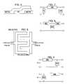
- FIG. 3is a plan view of a distributed element gap capacitor.
- FIG. 4is a cross-sectional view of an overlay capacitor.
- FIG. 5is a plan view of an interdigital (IDC) capacitor.
- FIG. 6is a schematic diagram depicting the two possible “L” matching circuit configurations.
- FIG. 7is a schematic diagram depicting a ⁇ matching network.
- FIG. 8is a schematic diagram depicting a “T” matching network.
- FIG. 9is a schematic diagram illustrating an exemplary first tuning circuit and an exemplary second tuning circuit.
- FIG. 10is a schematic block diagram of the present invention wireless communications device with a dual-band antenna matching system.
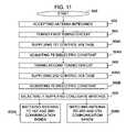
- FIG. 11is a flowchart illustrating the present invention method for dual-band impedance matching an antenna.
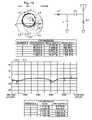
- FIG. 12is a Smith chart drawing depicting an exemplary antenna impedance, as charted between 824 and 1850 MHz.
- FIG. 13illustrates the impedance and associated return loss of the antenna of FIG. 12 , interfaced to the matching circuit of FIG. 9 .
- FIG. 14illustrates the impedance and associated return loss of the antenna of FIG. 12 , when the matching circuit first capacitor value is 4 pf and second capacitor value is 2 pf.
- FIG. 1is a schematic block diagram of the present invention dual-band antenna matching system.
- the system 100comprises an antenna 102 having an interface port on line 104 with a frequency-dependent impedance.
- a dual-band matching circuit 106includes an output port connected to the antenna interface port on line 104 .
- Line 104can be a transmission line, for example.
- the dual-band matching circuit 106selectively supplies a conjugate impedance at a first and a second communication band. Alternately, the dual-band matching circuit 106 supplies a conjugate match at a third and a fourth communication band.
- the antennahas a fixed impedance that varies with respect to frequency or communication band. However, in one aspect of the system, the antenna can be frequency tunable to further the dual-band matching process.
- the dual-band matching circuit 106supplies a conjugate impedance at the first communication band in response to a first tuned frequency, and simultaneously at the second communication band in response to a second tuned frequency. Alternately, the dual-band matching circuit 106 supplies a conjugate impedance at the third communication band in response to a third tuned frequency, and simultaneously at the fourth communication band in response to a fourth tuned frequency.
- the present inventionis useful for a person who owns a cell phone that operates in the cell band at 824 to 894 MHz, for example, when they are home.
- the user's networkmay operate in a different band, for example the GSM 880–960 MHz band.
- the userhas had to own two phones, one for home and one for travel.
- the present inventionpermits the user cell phone to operate efficiently in either environment, by selecting the conjugate match to the antenna.
- the selective conjugate matchcan be used to permit a cell phone to efficiently use a common antenna for both phone and GPS communications, to support 911 or location-based services.
- FIGS. 2 a and 2 bare graphs depicting the relationship between the first, second, third, and fourth communication bands. It should be understood that an antenna will function to some extent, even if poorly matched. Alternately, the antenna may be well matched, but have poor efficiencies at one or more of the communication bands. Some conventional antenna/matching circuit designs are able to cover multiple communication bands by providing a poor antenna match to an efficient antenna at one, or more frequencies. A poorly matched antenna is likely to have a lossy interface, or suffer with a greater reflected power (lower power throughput to/from the matching circuit).
- the antennais matched with a return loss, or voltage standing wave ratio (VSWR) of less (better) than 2:1, simultaneously in the first and second communication bands. That is, less than approximately 1/10 of the communicated power is reflected at the antenna/matching circuit interface. Further, the dual-band matching circuit simultaneously supplies matches in the third and fourth communication bands having a return loss of less (better) than 2:1.
- VSWRvoltage standing wave ratio
- the first, second, third, and fourth communication bandscover different frequency ranges.
- the communications bandsare shown with a frequency separation between bands, in some aspects the communication bands may overlap a common frequency span or be adjoined. Also note that a communication band may have a frequency span that is large enough to cover a plurality of communication channels.
- the first and third communications bandscover the same frequency span.
- the third communication bandis represented in phantom by dotted lines.
- the antennais unlikely to provide a constant impedance across all the frequencies of interest.
- the antennais likely to have a complex impedance, a combination of resistance and reactance (imaginary impedance), and that the complex impedance will vary across the communications bands.
- the conjugate impedances in the first, second, third, and fourth communication bands (frequency bands)can be determined.
- the matching circuitis able to supply a conjugate impedance to the antenna for each frequency (band) of interest. Alternately stated, the matching circuit is likely to supply a different conjugate match (complex impedance) for each communication band.
- a conjugate impedanceis understood to have the same real value, and opposite imaginary value, of the impedance to which it is matched. For example, for an antenna impedance value of (25+13j) ohms in the center of the first communication band, the conjugate impedance is (25 ⁇ 13j) ohms.
- a perfect conjugate matchis rare, expect at specific frequencies. Therefore, a conjugate match is typically optimizing for the center of a communication match, and/or efforts are made to have the matching circuit impedance track the antenna impedance across a frequency span.
- the antennamay incorporate some fixed-tuning elements or structures that provide convenient (easy to match) impedances in the first, second, third, and fourth communications bands. It should be understood that in the some aspects an antenna and antenna matching circuit may be combined into a single circuit referred to as an “antenna”.
- the dual-band matching circuit 106includes a first tuning circuit 110 selectively tunable to the first and third frequencies and a second tuning circuit 112 selectively tunable to the second and fourth frequencies.
- the first and second tuning circuits 110 / 112are shown in the figure as series-connected, however, a parallel arrangement of tuners is also possible.
- the first and second tuning circuits 110 / 112may each include a ferroelectric (FE) dielectric material (not shown) having a variable dielectric constant responsive to a control voltage.
- FEferroelectric
- the relationshipis more linear than voltage/capacitance curve of a voractor diode, especially in the tuning range between 0 and 3 V.
- the first and second tuning circuits 110 / 112have interfaces on lines 114 and 116 , respectively, to receive the control voltage. In some aspects, the first and second tuning circuits 110 / 112 accept a control voltage in the range between zero and three volts dc. This range of control voltages is compatible with the conventional battery sources used to power portable wireless devices.
- the ferroelectric variable capacitormay be an interdigital (IDC), gap, or overlay capacitor.
- matching circuitscan be implemented using lumped elements, distributed network elements, or some combination of the two.
- thin or thick FE filmscan be used in planar (microstrip, stripline, CPW, among others) passive matching circuits to vary the permittivity of the underlying substrate, thus effecting a change in the matching circuit's or resonator's electrical length or characteristic impedance.
- planar matching circuitsis familiar to anyone trained in the art of amplifier or circuit design.
- the matching networks herecan be hybrids and couplers, as well as the more conventional distributed inductive and capacitive structures. If lumped element matching components are used, then FE based tunable capacitors can be used in a similar manner to effect change.
- the linear dielectric variance, high Q, and low current consumption associated with FE capacitorsmake them desirable when compared to conventional tunable components, such as voractor diodes.
- FIG. 3is a plan view of a distributed element gap capacitor.
- the gap capacitorCompared to an IDC, the gap capacitor has a better Q, but lower capacitance per unit cross section (W).
- the IDC's capacitanceis greater due to the use of a number of fingers per unit cross section.
- large capacitanceC ⁇ 4.0 pF
- a gap capacitoroften can provide adequate capacitance.
- the inherently high value of ⁇ for most FE filmshelps provide relatively high capacitance per unit cross-section, W, compared to a conventional gap capacitor.
- FIG. 4is a cross-sectional view of an overlay capacitor.
- an overlay capacitorIn comparison to gap and interdigital capacitors, an overlay capacitor has the lowest L geom .
- An overlay capacitoris an example of a parallel plate geometry where the plate dimensions (length and width) are much greater than the plate separation. Given such a geometry, most of the electric field between the plates is uniform except for fringing along the edges. The fringing effect can be reduced significantly by the use of a guard band, as is well known in the art. Thus, the geometric loss from a parallel plate capacitor is quite low.
- parallel plate geometriescan provide high capacitances along with high tuning from small control voltage swings.
- FIG. 5is a plan view of an interdigital (IDC) capacitor.
- IDCinterdigital
- FIG. 6is a schematic diagram depicting two possible “L” matching circuit configurations.
- the two reactive elements 602 and 604may be any combination of capacitors and/or inductors.
- FIG. 7is a schematic diagram depicting a ⁇ matching network.
- the reactive elements 702 , 704 , and 706may be any combination of capacitors and/or inductors.
- FIG. 8is a schematic diagram depicting a “T” matching network.
- the reactive elements 802 , 804 , and 806may be any combination of capacitors and/or inductors.
- the dual-band matching circuit of the present inventionmay be enabled using a tunable series element or a tunable shunt element, such as a capacitor or inductor.
- the dual-band matching circuitany be an “L”, ⁇ , “T”, or combinations of the above-mentioned topologies.
- the dual-band matching circuitis not limited to any particular topology.
- FIG. 9is a schematic diagram illustrating an exemplary first tuning circuit 110 and an exemplary second tuning circuit 112 .
- the first tuning circuit 110includes a first inductor 200 with a fixed inductance value, and a first variable capacitor 202 with a selectable capacitance value.
- the second tuning circuit 112likewise includes a second inductor 204 with a fixed inductance value, and a second variable capacitor 206 with a selectable capacitance value.
- the first inductor 200is connected in shunt between the dual-band circuit output port on line 104 and a reference voltage.
- the reference voltagemay be ground.
- the first variable capacitor 202has a first terminal connected to the dual-band circuit output port on line 104 .
- the second inductor 204is connected in series between a second terminal of the first variable capacitor on line 208 and a dual-band matching circuit input port on line 210 .
- the second variable capacitor 206has a first terminal connected in shunt between the first variable capacitor second terminal on line 208 and the reference voltage.
- the inventionmay be enabled with other components and circuit topologies than the ones shown in FIG. 9 . Further, additional components, with either fixed or variable values, can be added to increase the number of poles, giving the circuits greater tunability and/or a sharper frequency response.
- the first inductor 200has an inductance of 8.2 nano-Henrys (nH) and the first variable capacitor 202 has a capacitance in the range between 1.5 and 4 picofarads (pF).
- the second inductor 204has an inductance of 4.7 nH.
- the second variable capacitor 206has a capacitance in the range between 0.7 and 2 pF.
- the first frequencyis responsive to the first variable capacitor having a value of 1.5 pF, and the third frequency is responsive to the value of 4 pF.
- the second frequencyis responsive to the second variable capacitor having a value of 0.7 pF, and the fourth frequency is responsive to the value of 2 pF.
- the first and third communication bandsare the same (see FIG. 2 b ). That is, the matching circuit provides impedance matches for the first and second communications bands, or the first (third) and fourth communications bands.
- the dual-band matching circuitsupplies conjugate impedances at a first (third) communication band in the range between 824 and 894 megahertz (MHz), at a second communication band in the range of 1850 and 1990 MHz, and at a fourth communication band in the range of 1565 to 1585 MHz.
- FIG. 12is a Smith chart drawing depicting an exemplary antenna impedance, as charted between 824 and 1850 MHz.
- FIG. 13illustrates the impedance and associated return loss of the antenna of FIG. 12 , interfaced to the matching circuit of FIG. 9 .
- the matching circuit first capacitor valueis 1.5 pf and second capacitor value is 0.7 pf.
- Conjugate impedancesare supplied at approximately 850 and 1900 MHz.
- FIG. 14illustrates the impedance and associated return loss of the antenna of FIG. 12 , when the matching circuit first capacitor value is 4 pf and second capacitor value is 2 pf.
- Conjugate impedancesare supplied at approximately 850 and 1575 MHz.
- the first and third communications bandscover different frequency ranges.
- the dual-band matching circuitcan supply conjugate impedances at a first communication band in the range between 824 and 894 MHz, at a second communication band in the range of 1850 and 1990 MHz, at a third communication band in the range of 880 to 960 MHz, and at a fourth communication band in the range of 1710 to 1880 MHz.
- the matching circuitcan also supply conjugate impedances in the UMTS band between 1850 and 2200 MHz is also
- Other communication bands, bandwidths, and bandwidth spacingsmay be obtained by selecting different component values in the first and second tuning circuits.
- the conceptcan be extended to a matching circuit that is able provide dual-band conjugate matches for a plurality of communication band combinations (more than 2 sets of dual-band combinations).
- the exemplary tuning circuitsare enabled with FE capacitors, it is possible to build the circuits with conventional variable components, such as voractor diodes or mechanically tunable capacitors, or a combination of FE and conventional variable components.
- FIG. 10is a schematic block diagram of the present invention wireless communications device with a dual-band antenna matching system.
- the device 400comprises a transceiver 402 having a wireless communications port on line 210 to communicate in a first, second, third, and fourth communication band.
- An antenna 102has an interface port on line 104 with a frequency-dependent impedance.
- a dual-band matching circuit 106includes an input port connected to the transceiver wireless communications port on line 210 and an output port connected to the antenna interface port on line 104 .
- the dual-band matching circuit 106selectively supplies a conjugate impedance at either the first and second communication band, or the third and fourth communication band.
- the dual-band matching circuit 106supplies a conjugate impedance for the first communication band in response to a first tuned frequency, and simultaneously for the second communication band in response to a second tuned frequency.
- the dual-band matching circuit 106supplies a conjugate impedance for the third communication band in response to a third tuned frequency, and simultaneously for the fourth communication band in response to a fourth tuned frequency.
- the dual-band matching circuitfurther includes a first tuning circuit 110 selectively tunable to the first and third frequencies, and a second tuning circuit 112 selectively tunable to the second and fourth frequencies. Details of the first and second tuning circuits 110 and 112 have been provided above, and will not be repeated in the interest of brevity.
- the first and third communication bandsare transmission bandwidths, while the second and fourth communication bands are receive bandwidths.
- the transceiver 402incorporates transmit and receive functions. In another aspect, all four communication bands are either receiver or transmission bandwidths.
- the communication bandsmay support telephone, Bluetooth, GPS, and radio communications.
- the transceiver 402is selectively tuned to relatively narrow channels. Each communication band typically includes a plurality of frequency-consecutive channels.
- the dual-band matching circuit 106may supply conjugate impedances at either the first and second communication band, or the third and fourth communication band, where the first and third communication bands are the same.
- the dual-band matching circuit 106may supply conjugate impedances at a first (third) communication band in the range between 824 and 894 megahertz (MHz), at a second communication band in the range of 1850 and 1990 MHz, and at a fourth communication band in the range of 1565 to 1585 MHz.
- the first and third communication bandscover different frequency ranges and the dual-band matching circuit 106 supplies conjugate impedances at a first communication band in the range between 824 and 894 megahertz (MHz), at a second communication band in the range of 1850 and 1990 MHz, at a third communication band in the range of 880 to 960 MHz, and at a fourth communication band in the range of 1710 to 1880 MHz.
- a first communication bandin the range between 824 and 894 megahertz (MHz)
- a second communication bandin the range of 1850 and 1990 MHz
- a third communication bandin the range of 880 to 960 MHz
- a fourth communication bandin the range of 1710 to 1880 MHz.
- Other communication bands, bandwidths, and bandwidth spacingsmay be obtained by selecting different component values in the first and second tuning circuits. Further, it would be possible to extend the matching circuit concept developed above to a matching circuit that is able to tune a multi-band antenna between different communications bands. Likewise, the concept can be extended to a matching circuit that is able provide dual-band conjugate matches for a plurality of communication band combinations.
- the exemplary tuning circuitsare enabled with FE capacitors, it is possible to build the circuits with conventional variable components, or a combination of FE and conventional variable components.
- FIG. 11is a flowchart illustrating the present invention method for dual-band impedance matching an antenna. Although the method is depicted as a sequence of numbered steps for clarity, no order should be inferred from the numbering unless explicitly stated. It should be understood that some of these steps may be skipped, performed in parallel, or performed without the requirement of maintaining a strict order of sequence.
- the methodstarts at Step 600 .
- Step 602accepts a frequency-dependent impedance from an antenna.
- Step 608selectively supplies a conjugate impedance match for the antenna at either a first and a second communication band, or a third and a fourth communication band.
- Step 608uses a matching topology such as a series tunable element, a shunt tunable element, an “L” network, a ⁇ network, a “T” network, or combinations of the above-mentioned topologies.
- Step 604tunes a first tuning circuit to a first frequency.
- Step 606simultaneously tunes a second tuning circuit to a second frequency.
- selectively supplying the conjugate impedance for matching the antenna at the first and second communication bandsincludes a Step 608 a that matches the antenna at the first communication band in response to the first frequency, and simultaneously matches the antenna at the second communication band in response to the second frequency.
- Step 604tunes the first tuning circuit to a third frequency and Step 606 tunes the second tuning circuit to a fourth frequency. Then, a Step 608 b matches the antenna at the third communication band in response to the third frequency, and simultaneously matches the antenna at the fourth communication band in response to the fourth frequency.
- Step 604 and Step 606include substeps.
- Step 604 asupplies a first control voltage to the first tuning circuits, and Step 604 b adjusts the dielectric constant of a ferroelectric (FE) dielectric material in response to the control voltages.
- Step 606 asupplies a second control voltage to the second tuning circuits, and Step 606 b adjusts the dielectric constant of an FE dielectric material in response to the control voltages.
- FEferroelectric
- the first tuning circuit(in Step 604 ) tunes a first variable capacitor, with a selectable capacitance value, connected to a first inductor with a fixed inductance value.
- the second tuning circuittunes a second variable capacitor, with a selectable capacitance value, connected to a second inductor with a fixed inductance value.
- Step 604may include tuning a first variable capacitor with a selectable capacitance value in the range between 1.5 and 4 picofarads (pF), connected to a first inductor with a fixed inductance value of 8.2 nano-Henrys (nH).
- Step 606may include tuning a second variable capacitor with a selectable capacitance value in the range of 0.7 and 2 pF, connected to a second inductor with a fixed inductance value of 4.7 nH.
- Step 604tunes the first frequency by using a first variable capacitor value of 1.5 pF, and tunes to the third frequency by using a first variable capacitor value of 4 pF.
- Step 606the second tuning circuit tunes to the second frequency by using a second variable capacitor value of 0.7 pF, and tunes to the fourth frequency using a second variable capacitor value of 2 pF.
- Step 608 amatches the antenna to a first communication band in the range of 824 to 894 MHz and a second communication band in the range of 1850 to 1990 MHz (using the first and second frequencies, respectively).
- Step 608 bmatches the antenna to a third communication band in the range of 824 to 894 MHz a fourth communication band in the range of 1565 to 1585 MHz.
- the first and third communication bandsare the same.
- Step 608 amay match the antenna to a first communication band in the range of 824 to 894 MHz and a second communication band in the range of 1850 to 1990 MHz.
- Step 608 bmatches the antenna to a third communication band in the range of 880–960 MHz a fourth communication band in the range of 1710–1880 MHz.
- a dual-band antenna matching system, a wireless device using the dual-band matching system, and a method for dual-band antenna matchinghave been provided.
- Exemplary component values, circuit configurations, and frequencieshave been presented to clarify the invention.
- the inventionis not necessarily limited to just these examples.
- Variable value electrical componentshave also been presented using FE materials.
- tunings changescan also be enabled when FE material is used as a circuit board dielectric, to change the electrical length of a microstrip inductor for example.
- Other variations and embodiments of the inventionwill occur to those skilled in the art.
Landscapes
- Physics & Mathematics (AREA)
- Engineering & Computer Science (AREA)
- Electromagnetism (AREA)
- Power Engineering (AREA)
- Computer Networks & Wireless Communication (AREA)
- Signal Processing (AREA)
- General Physics & Mathematics (AREA)
- Microelectronics & Electronic Packaging (AREA)
- Transceivers (AREA)
- Input Circuits Of Receivers And Coupling Of Receivers And Audio Equipment (AREA)
Abstract
Description
Claims (24)
Priority Applications (25)
| Application Number | Priority Date | Filing Date | Title |
|---|---|---|---|
| US10/899,278US7180467B2 (en) | 2002-02-12 | 2004-07-26 | System and method for dual-band antenna matching |
| PCT/US2005/024991WO2006019910A1 (en) | 2004-07-26 | 2005-07-14 | Full-duplex antenna system and method |
| CA002575087ACA2575087A1 (en) | 2004-07-26 | 2005-07-14 | Full-duplex antenna system and method |
| EP05771518AEP1779466A1 (en) | 2004-07-26 | 2005-07-14 | Full-duplex antenna system and method |
| KR1020077002572AKR100918160B1 (en) | 2004-07-26 | 2005-07-14 | Bidirectional Antenna System and Method |
| BRPI0513786-1ABRPI0513786A (en) | 2004-07-26 | 2005-07-14 | method and system for full duplex antenna |
| EP09163136AEP2096712A1 (en) | 2004-07-26 | 2005-07-14 | Antenna system comprising an adjustable inverted-F antenna |
| JP2007522571AJP4327218B2 (en) | 2004-07-26 | 2005-07-14 | Full-duplex antenna system and method |
| AU2005275068AAU2005275068B2 (en) | 2004-07-26 | 2005-07-14 | Full-duplex antenna system and method |
| PCT/US2005/025557WO2006020285A1 (en) | 2004-07-26 | 2005-07-19 | System and method for dual-band antenna matching |
| EP05775498AEP1779467A1 (en) | 2004-07-26 | 2005-07-19 | System and method for dual-band antenna matching |
| CN200580025314.6ACN101002362A (en) | 2004-07-26 | 2005-07-19 | Systems and methods for dual-band antenna matching |
| CA002575120ACA2575120A1 (en) | 2004-07-26 | 2005-07-19 | System and method for dual-band antenna matching |
| JP2007522651AJP4597192B2 (en) | 2004-07-26 | 2005-07-19 | System and method for dual-band antenna matching |
| KR1020077002722AKR100872249B1 (en) | 2004-07-26 | 2005-07-19 | System and method for dual-band antenna matching |
| BRPI0513791-8ABRPI0513791A (en) | 2004-07-26 | 2005-07-19 | Dual band antenna wedding system and method |
| AU2005274709AAU2005274709B2 (en) | 2004-07-26 | 2005-07-19 | System and method for dual-band antenna matching |
| EP05774973AEP1779462A1 (en) | 2004-07-26 | 2005-07-21 | System and method for impedance matching an antenna to sub-bands in a communication band |
| CN200580025362.5ACN101002360B (en) | 2004-07-26 | 2005-07-21 | System and method for impedance matching an antenna to sub-bands in a communication band |
| AU2005269601AAU2005269601B2 (en) | 2004-07-26 | 2005-07-21 | System and method for impedance matching an antenna to sub-bands in a communication band |
| KR1020077002574AKR100921890B1 (en) | 2004-07-26 | 2005-07-21 | System and method for impedance matching antennas to sub-bands of communication bands |
| CA002574944ACA2574944A1 (en) | 2004-07-26 | 2005-07-21 | System and method for impedance matching an antenna to sub-bands in a communication band |
| JP2007523659AJP4303770B2 (en) | 2004-07-26 | 2005-07-21 | System and method for impedance matching an antenna to a subband within a communication band |
| BRPI0513787-0ABRPI0513787A (en) | 2004-07-26 | 2005-07-21 | system and method for impedance matching an antenna to subbands in a communication band |
| PCT/US2005/026001WO2006014795A1 (en) | 2004-07-26 | 2005-07-21 | System and method for impedance matching an antenna to sub-bands in a communication band |
Applications Claiming Priority (4)
| Application Number | Priority Date | Filing Date | Title |
|---|---|---|---|
| US10/075,896US6765540B2 (en) | 2001-04-11 | 2002-02-12 | Tunable antenna matching circuit |
| US10/117,628US6861985B2 (en) | 2001-04-11 | 2002-04-04 | Ferroelectric antenna and method for tuning same |
| US10/120,603US6885341B2 (en) | 2001-04-11 | 2002-04-09 | Inverted-F ferroelectric antenna |
| US10/899,278US7180467B2 (en) | 2002-02-12 | 2004-07-26 | System and method for dual-band antenna matching |
Related Parent Applications (3)
| Application Number | Title | Priority Date | Filing Date |
|---|---|---|---|
| US10/075,896Continuation-In-PartUS6765540B2 (en) | 2001-04-11 | 2002-02-12 | Tunable antenna matching circuit |
| US10/117,628Continuation-In-PartUS6861985B2 (en) | 2001-04-11 | 2002-04-04 | Ferroelectric antenna and method for tuning same |
| US10/120,603Continuation-In-PartUS6885341B2 (en) | 2001-04-11 | 2002-04-09 | Inverted-F ferroelectric antenna |
Publications (2)
| Publication Number | Publication Date |
|---|---|
| US20040263411A1 US20040263411A1 (en) | 2004-12-30 |
| US7180467B2true US7180467B2 (en) | 2007-02-20 |
Family
ID=38693402
Family Applications (1)
| Application Number | Title | Priority Date | Filing Date |
|---|---|---|---|
| US10/899,278Expired - LifetimeUS7180467B2 (en) | 2002-02-12 | 2004-07-26 | System and method for dual-band antenna matching |
Country Status (2)
| Country | Link |
|---|---|
| US (1) | US7180467B2 (en) |
| CN (1) | CN101002362A (en) |
Cited By (220)
| Publication number | Priority date | Publication date | Assignee | Title |
|---|---|---|---|---|
| US20060160501A1 (en)* | 2000-07-20 | 2006-07-20 | Greg Mendolia | Tunable microwave devices with auto-adjusting matching circuit |
| US20070018895A1 (en)* | 2003-03-19 | 2007-01-25 | Thomas Bolin | Switchable antenna arrangement |
| US20070197180A1 (en)* | 2006-01-14 | 2007-08-23 | Mckinzie William E Iii | Adaptive impedance matching module (AIMM) control architectures |
| US20070200766A1 (en)* | 2006-01-14 | 2007-08-30 | Mckinzie William E Iii | Adaptively tunable antennas and method of operation therefore |
| US20070285326A1 (en)* | 2006-01-14 | 2007-12-13 | Mckinzie William E | Adaptively tunable antennas incorporating an external probe to monitor radiated power |
| US20080106349A1 (en)* | 2006-11-08 | 2008-05-08 | Mckinzie William E | Adaptive impedance matching apparatus, system and method |
| US20080122712A1 (en)* | 2006-11-28 | 2008-05-29 | Agile Rf, Inc. | Tunable antenna including tunable capacitor inserted inside the antenna |
| US20080122553A1 (en)* | 2006-11-08 | 2008-05-29 | Mckinzie William E | Adaptive impedance matching module |
| US20080136714A1 (en)* | 2006-12-12 | 2008-06-12 | Daniel Boire | Antenna tuner with zero volts impedance fold back |
| US20090039976A1 (en)* | 2006-11-08 | 2009-02-12 | Mckinzie Iii William E | Adaptive impedance matching apparatus,system and method with improved dynamic range |
| US20090046030A1 (en)* | 2007-06-08 | 2009-02-19 | Arizona Board Of Regents For And On Behalf Of Arizona State University | Automatic Antenna Tuning Unit for Software-Defined and Cognitive Radio |
| US20090121963A1 (en)* | 2007-11-14 | 2009-05-14 | Greene Matthew R | Tuning matching circuits for transmitter and receiver bands as a function of transmitter metrics |
| US20100090760A1 (en)* | 2008-10-14 | 2010-04-15 | Paratek Microwave, Inc. | Low-distortion voltage variable capacitor assemblies |
| US20100164831A1 (en)* | 2008-12-31 | 2010-07-01 | Rentz Mark L | Hooked Turnstile Antenna for Navigation and Communication |
| US20110014886A1 (en)* | 2007-04-23 | 2011-01-20 | Paratek Microwave, Inc. | Techniques for improved adaptive impedance matching |
| US20110018653A1 (en)* | 2009-07-27 | 2011-01-27 | Avago Technologies Wireless Ip (Singapore) Pte. Ltd. | Duplexer having resonator filters |
| US7880681B2 (en) | 2008-02-26 | 2011-02-01 | Navcom Technology, Inc. | Antenna with dual band lumped element impedance matching |
| US20110053524A1 (en)* | 2009-08-25 | 2011-03-03 | Paratek Microwave, Inc. | Method and apparatus for calibrating a communication device |
| US20110063042A1 (en)* | 2000-07-20 | 2011-03-17 | Paratek Microwave, Inc. | Tunable microwave devices with auto-adjusting matching circuit |
| US20110086630A1 (en)* | 2009-10-10 | 2011-04-14 | Paratek Microwave, Inc. | Method and apparatus for managing operations of a communication device |
| US20110163161A1 (en)* | 2008-08-25 | 2011-07-07 | Nxp B.V. | Reconfigurable radio-frequency front-end |
| US20110273354A1 (en)* | 2008-05-08 | 2011-11-10 | Comrod As | Transfer Unit for Radio Frequency Signals and Method for Alternatively Using an Electrical Antenna or a Magnetic Antenna with a Classic Antenna Tuner |
| US8072285B2 (en) | 2008-09-24 | 2011-12-06 | Paratek Microwave, Inc. | Methods for tuning an adaptive impedance matching network with a look-up table |
| US8193877B2 (en) | 2009-11-30 | 2012-06-05 | Avago Technologies Wireless Ip (Singapore) Pte. Ltd. | Duplexer with negative phase shifting circuit |
| US8213886B2 (en) | 2007-05-07 | 2012-07-03 | Paratek Microwave, Inc. | Hybrid techniques for antenna retuning utilizing transmit and receive power information |
| US8432234B2 (en) | 2010-11-08 | 2013-04-30 | Research In Motion Rf, Inc. | Method and apparatus for tuning antennas in a communication device |
| US8594584B2 (en) | 2011-05-16 | 2013-11-26 | Blackberry Limited | Method and apparatus for tuning a communication device |
| US8626083B2 (en) | 2011-05-16 | 2014-01-07 | Blackberry Limited | Method and apparatus for tuning a communication device |
| US8655286B2 (en) | 2011-02-25 | 2014-02-18 | Blackberry Limited | Method and apparatus for tuning a communication device |
| US8680944B2 (en) | 2011-01-13 | 2014-03-25 | Avago Technologies General Ip (Singapore) Pte. Ltd. | Single-chip duplexer with isolation shield between transmit and receive filters |
| US8686655B2 (en) | 2010-07-22 | 2014-04-01 | Panasonic Corporation | Lighting circuit, lamp, and illumination apparatus |
| US8712340B2 (en) | 2011-02-18 | 2014-04-29 | Blackberry Limited | Method and apparatus for radio antenna frequency tuning |
| US20140179239A1 (en)* | 2012-12-21 | 2014-06-26 | Apple Inc. | Methods and Apparatus for Performing Passive Antenna Testing with Active Antenna Tuning Device Control |
| USRE44998E1 (en) | 2000-07-20 | 2014-07-08 | Blackberry Limited | Optimized thin film capacitors |
| US8776002B2 (en) | 2011-09-06 | 2014-07-08 | Variable Z0, Ltd. | Variable Z0 antenna device design system and method |
| US8803631B2 (en) | 2010-03-22 | 2014-08-12 | Blackberry Limited | Method and apparatus for adapting a variable impedance network |
| US8860525B2 (en) | 2010-04-20 | 2014-10-14 | Blackberry Limited | Method and apparatus for managing interference in a communication device |
| US8948889B2 (en) | 2012-06-01 | 2015-02-03 | Blackberry Limited | Methods and apparatus for tuning circuit components of a communication device |
| US8988288B2 (en) | 2012-07-12 | 2015-03-24 | Blackberry Limited | Tri-band antenna for noncellular wireless applications |
| US20150155846A1 (en)* | 2012-05-22 | 2015-06-04 | Nokia Corporation | Apparatus and methods for wireless communication |
| US20150380812A1 (en)* | 2014-03-13 | 2015-12-31 | Google Technology Holdings LLC | Hand grip sensor for external chassis antenna |
| US9246223B2 (en) | 2012-07-17 | 2016-01-26 | Blackberry Limited | Antenna tuning for multiband operation |
| US20160029385A1 (en)* | 2014-07-28 | 2016-01-28 | Celeno Communications (Israel) Ltd. | Concurrent dual-band wlan device using mcm |
| US9312919B1 (en) | 2014-10-21 | 2016-04-12 | At&T Intellectual Property I, Lp | Transmission device with impairment compensation and methods for use therewith |
| US20160126619A1 (en)* | 2014-10-30 | 2016-05-05 | Mediatek Singapore Pte. Ltd. | Wireless communication unit, integrated circuit and method for antenna tuning |
| US9350405B2 (en) | 2012-07-19 | 2016-05-24 | Blackberry Limited | Method and apparatus for antenna tuning and power consumption management in a communication device |
| US9362891B2 (en) | 2012-07-26 | 2016-06-07 | Blackberry Limited | Methods and apparatus for tuning a communication device |
| US9374113B2 (en) | 2012-12-21 | 2016-06-21 | Blackberry Limited | Method and apparatus for adjusting the timing of radio antenna tuning |
| US9406444B2 (en) | 2005-11-14 | 2016-08-02 | Blackberry Limited | Thin film capacitors |
| US9413066B2 (en) | 2012-07-19 | 2016-08-09 | Blackberry Limited | Method and apparatus for beam forming and antenna tuning in a communication device |
| US9461706B1 (en) | 2015-07-31 | 2016-10-04 | At&T Intellectual Property I, Lp | Method and apparatus for exchanging communication signals |
| US9467870B2 (en) | 2013-11-06 | 2016-10-11 | At&T Intellectual Property I, L.P. | Surface-wave communications and methods thereof |
| US9479266B2 (en) | 2013-12-10 | 2016-10-25 | At&T Intellectual Property I, L.P. | Quasi-optical coupler |
| US9490869B1 (en) | 2015-05-14 | 2016-11-08 | At&T Intellectual Property I, L.P. | Transmission medium having multiple cores and methods for use therewith |
| US9503189B2 (en) | 2014-10-10 | 2016-11-22 | At&T Intellectual Property I, L.P. | Method and apparatus for arranging communication sessions in a communication system |
| US9509415B1 (en) | 2015-06-25 | 2016-11-29 | At&T Intellectual Property I, L.P. | Methods and apparatus for inducing a fundamental wave mode on a transmission medium |
| US9520945B2 (en) | 2014-10-21 | 2016-12-13 | At&T Intellectual Property I, L.P. | Apparatus for providing communication services and methods thereof |
| US9525524B2 (en) | 2013-05-31 | 2016-12-20 | At&T Intellectual Property I, L.P. | Remote distributed antenna system |
| US9525210B2 (en) | 2014-10-21 | 2016-12-20 | At&T Intellectual Property I, L.P. | Guided-wave transmission device with non-fundamental mode propagation and methods for use therewith |
| US9531427B2 (en) | 2014-11-20 | 2016-12-27 | At&T Intellectual Property I, L.P. | Transmission device with mode division multiplexing and methods for use therewith |
| US9564947B2 (en) | 2014-10-21 | 2017-02-07 | At&T Intellectual Property I, L.P. | Guided-wave transmission device with diversity and methods for use therewith |
| US9577306B2 (en) | 2014-10-21 | 2017-02-21 | At&T Intellectual Property I, L.P. | Guided-wave transmission device and methods for use therewith |
| US9584191B2 (en) | 2013-12-20 | 2017-02-28 | Southern Avionics Co. | Antenna tuning unit |
| US9608740B2 (en) | 2015-07-15 | 2017-03-28 | At&T Intellectual Property I, L.P. | Method and apparatus for launching a wave mode that mitigates interference |
| US9608692B2 (en) | 2015-06-11 | 2017-03-28 | At&T Intellectual Property I, L.P. | Repeater and methods for use therewith |
| US9615269B2 (en) | 2014-10-02 | 2017-04-04 | At&T Intellectual Property I, L.P. | Method and apparatus that provides fault tolerance in a communication network |
| US9628854B2 (en) | 2014-09-29 | 2017-04-18 | At&T Intellectual Property I, L.P. | Method and apparatus for distributing content in a communication network |
| US9628116B2 (en) | 2015-07-14 | 2017-04-18 | At&T Intellectual Property I, L.P. | Apparatus and methods for transmitting wireless signals |
| US9640850B2 (en) | 2015-06-25 | 2017-05-02 | At&T Intellectual Property I, L.P. | Methods and apparatus for inducing a non-fundamental wave mode on a transmission medium |
| US9654173B2 (en) | 2014-11-20 | 2017-05-16 | At&T Intellectual Property I, L.P. | Apparatus for powering a communication device and methods thereof |
| US9653770B2 (en) | 2014-10-21 | 2017-05-16 | At&T Intellectual Property I, L.P. | Guided wave coupler, coupling module and methods for use therewith |
| US9667317B2 (en) | 2015-06-15 | 2017-05-30 | At&T Intellectual Property I, L.P. | Method and apparatus for providing security using network traffic adjustments |
| US9680670B2 (en) | 2014-11-20 | 2017-06-13 | At&T Intellectual Property I, L.P. | Transmission device with channel equalization and control and methods for use therewith |
| US9685992B2 (en) | 2014-10-03 | 2017-06-20 | At&T Intellectual Property I, L.P. | Circuit panel network and methods thereof |
| US9692101B2 (en) | 2014-08-26 | 2017-06-27 | At&T Intellectual Property I, L.P. | Guided wave couplers for coupling electromagnetic waves between a waveguide surface and a surface of a wire |
| US9699785B2 (en) | 2012-12-05 | 2017-07-04 | At&T Intellectual Property I, L.P. | Backhaul link for distributed antenna system |
| US9705561B2 (en) | 2015-04-24 | 2017-07-11 | At&T Intellectual Property I, L.P. | Directional coupling device and methods for use therewith |
| US9705571B2 (en) | 2015-09-16 | 2017-07-11 | At&T Intellectual Property I, L.P. | Method and apparatus for use with a radio distributed antenna system |
| US9722318B2 (en) | 2015-07-14 | 2017-08-01 | At&T Intellectual Property I, L.P. | Method and apparatus for coupling an antenna to a device |
| US9729197B2 (en) | 2015-10-01 | 2017-08-08 | At&T Intellectual Property I, L.P. | Method and apparatus for communicating network management traffic over a network |
| US9735833B2 (en) | 2015-07-31 | 2017-08-15 | At&T Intellectual Property I, L.P. | Method and apparatus for communications management in a neighborhood network |
| US9742462B2 (en) | 2014-12-04 | 2017-08-22 | At&T Intellectual Property I, L.P. | Transmission medium and communication interfaces and methods for use therewith |
| US9749013B2 (en) | 2015-03-17 | 2017-08-29 | At&T Intellectual Property I, L.P. | Method and apparatus for reducing attenuation of electromagnetic waves guided by a transmission medium |
| US9748626B2 (en) | 2015-05-14 | 2017-08-29 | At&T Intellectual Property I, L.P. | Plurality of cables having different cross-sectional shapes which are bundled together to form a transmission medium |
| US9749053B2 (en) | 2015-07-23 | 2017-08-29 | At&T Intellectual Property I, L.P. | Node device, repeater and methods for use therewith |
| US9755697B2 (en) | 2014-09-15 | 2017-09-05 | At&T Intellectual Property I, L.P. | Method and apparatus for sensing a condition in a transmission medium of electromagnetic waves |
| US9762289B2 (en) | 2014-10-14 | 2017-09-12 | At&T Intellectual Property I, L.P. | Method and apparatus for transmitting or receiving signals in a transportation system |
| US9769128B2 (en) | 2015-09-28 | 2017-09-19 | At&T Intellectual Property I, L.P. | Method and apparatus for encryption of communications over a network |
| US9769020B2 (en) | 2014-10-21 | 2017-09-19 | At&T Intellectual Property I, L.P. | Method and apparatus for responding to events affecting communications in a communication network |
| US9769826B2 (en) | 2011-08-05 | 2017-09-19 | Blackberry Limited | Method and apparatus for band tuning in a communication device |
| US9780834B2 (en) | 2014-10-21 | 2017-10-03 | At&T Intellectual Property I, L.P. | Method and apparatus for transmitting electromagnetic waves |
| US9793951B2 (en) | 2015-07-15 | 2017-10-17 | At&T Intellectual Property I, L.P. | Method and apparatus for launching a wave mode that mitigates interference |
| US9793955B2 (en) | 2015-04-24 | 2017-10-17 | At&T Intellectual Property I, Lp | Passive electrical coupling device and methods for use therewith |
| US9793954B2 (en) | 2015-04-28 | 2017-10-17 | At&T Intellectual Property I, L.P. | Magnetic coupling device and methods for use therewith |
| US9800327B2 (en) | 2014-11-20 | 2017-10-24 | At&T Intellectual Property I, L.P. | Apparatus for controlling operations of a communication device and methods thereof |
| US9820146B2 (en) | 2015-06-12 | 2017-11-14 | At&T Intellectual Property I, L.P. | Method and apparatus for authentication and identity management of communicating devices |
| US9836957B2 (en) | 2015-07-14 | 2017-12-05 | At&T Intellectual Property I, L.P. | Method and apparatus for communicating with premises equipment |
| US9838896B1 (en) | 2016-12-09 | 2017-12-05 | At&T Intellectual Property I, L.P. | Method and apparatus for assessing network coverage |
| US9847850B2 (en) | 2014-10-14 | 2017-12-19 | At&T Intellectual Property I, L.P. | Method and apparatus for adjusting a mode of communication in a communication network |
| US9847566B2 (en) | 2015-07-14 | 2017-12-19 | At&T Intellectual Property I, L.P. | Method and apparatus for adjusting a field of a signal to mitigate interference |
| US9853363B2 (en) | 2012-07-06 | 2017-12-26 | Blackberry Limited | Methods and apparatus to control mutual coupling between antennas |
| US9853342B2 (en) | 2015-07-14 | 2017-12-26 | At&T Intellectual Property I, L.P. | Dielectric transmission medium connector and methods for use therewith |
| US9860075B1 (en) | 2016-08-26 | 2018-01-02 | At&T Intellectual Property I, L.P. | Method and communication node for broadband distribution |
| US9865911B2 (en) | 2015-06-25 | 2018-01-09 | At&T Intellectual Property I, L.P. | Waveguide system for slot radiating first electromagnetic waves that are combined into a non-fundamental wave mode second electromagnetic wave on a transmission medium |
| US9866309B2 (en) | 2015-06-03 | 2018-01-09 | At&T Intellectual Property I, Lp | Host node device and methods for use therewith |
| US9871282B2 (en) | 2015-05-14 | 2018-01-16 | At&T Intellectual Property I, L.P. | At least one transmission medium having a dielectric surface that is covered at least in part by a second dielectric |
| US9871283B2 (en) | 2015-07-23 | 2018-01-16 | At&T Intellectual Property I, Lp | Transmission medium having a dielectric core comprised of plural members connected by a ball and socket configuration |
| US9876570B2 (en) | 2015-02-20 | 2018-01-23 | At&T Intellectual Property I, Lp | Guided-wave transmission device with non-fundamental mode propagation and methods for use therewith |
| US9876605B1 (en) | 2016-10-21 | 2018-01-23 | At&T Intellectual Property I, L.P. | Launcher and coupling system to support desired guided wave mode |
| US9876264B2 (en) | 2015-10-02 | 2018-01-23 | At&T Intellectual Property I, Lp | Communication system, guided wave switch and methods for use therewith |
| US9882277B2 (en) | 2015-10-02 | 2018-01-30 | At&T Intellectual Property I, Lp | Communication device and antenna assembly with actuated gimbal mount |
| US9882257B2 (en) | 2015-07-14 | 2018-01-30 | At&T Intellectual Property I, L.P. | Method and apparatus for launching a wave mode that mitigates interference |
| US9893795B1 (en) | 2016-12-07 | 2018-02-13 | At&T Intellectual Property I, Lp | Method and repeater for broadband distribution |
| US9904535B2 (en) | 2015-09-14 | 2018-02-27 | At&T Intellectual Property I, L.P. | Method and apparatus for distributing software |
| US9906269B2 (en) | 2014-09-17 | 2018-02-27 | At&T Intellectual Property I, L.P. | Monitoring and mitigating conditions in a communication network |
| US9912382B2 (en) | 2015-06-03 | 2018-03-06 | At&T Intellectual Property I, Lp | Network termination and methods for use therewith |
| US9913139B2 (en) | 2015-06-09 | 2018-03-06 | At&T Intellectual Property I, L.P. | Signal fingerprinting for authentication of communicating devices |
| US9911020B1 (en) | 2016-12-08 | 2018-03-06 | At&T Intellectual Property I, L.P. | Method and apparatus for tracking via a radio frequency identification device |
| US9912027B2 (en) | 2015-07-23 | 2018-03-06 | At&T Intellectual Property I, L.P. | Method and apparatus for exchanging communication signals |
| US9912419B1 (en) | 2016-08-24 | 2018-03-06 | At&T Intellectual Property I, L.P. | Method and apparatus for managing a fault in a distributed antenna system |
| US9917341B2 (en) | 2015-05-27 | 2018-03-13 | At&T Intellectual Property I, L.P. | Apparatus and method for launching electromagnetic waves and for modifying radial dimensions of the propagating electromagnetic waves |
| US9927517B1 (en) | 2016-12-06 | 2018-03-27 | At&T Intellectual Property I, L.P. | Apparatus and methods for sensing rainfall |
| US9948354B2 (en) | 2015-04-28 | 2018-04-17 | At&T Intellectual Property I, L.P. | Magnetic coupling device with reflective plate and methods for use therewith |
| US9948333B2 (en) | 2015-07-23 | 2018-04-17 | At&T Intellectual Property I, L.P. | Method and apparatus for wireless communications to mitigate interference |
| US9954287B2 (en) | 2014-11-20 | 2018-04-24 | At&T Intellectual Property I, L.P. | Apparatus for converting wireless signals and electromagnetic waves and methods thereof |
| US9967173B2 (en) | 2015-07-31 | 2018-05-08 | At&T Intellectual Property I, L.P. | Method and apparatus for authentication and identity management of communicating devices |
| US9973940B1 (en) | 2017-02-27 | 2018-05-15 | At&T Intellectual Property I, L.P. | Apparatus and methods for dynamic impedance matching of a guided wave launcher |
| US9991580B2 (en) | 2016-10-21 | 2018-06-05 | At&T Intellectual Property I, L.P. | Launcher and coupling system for guided wave mode cancellation |
| US9997819B2 (en) | 2015-06-09 | 2018-06-12 | At&T Intellectual Property I, L.P. | Transmission medium and method for facilitating propagation of electromagnetic waves via a core |
| US9999038B2 (en) | 2013-05-31 | 2018-06-12 | At&T Intellectual Property I, L.P. | Remote distributed antenna system |
| US9998870B1 (en) | 2016-12-08 | 2018-06-12 | At&T Intellectual Property I, L.P. | Method and apparatus for proximity sensing |
| US10003393B2 (en) | 2014-12-16 | 2018-06-19 | Blackberry Limited | Method and apparatus for antenna selection |
| US10009067B2 (en) | 2014-12-04 | 2018-06-26 | At&T Intellectual Property I, L.P. | Method and apparatus for configuring a communication interface |
| US10009063B2 (en) | 2015-09-16 | 2018-06-26 | At&T Intellectual Property I, L.P. | Method and apparatus for use with a radio distributed antenna system having an out-of-band reference signal |
| US10009901B2 (en) | 2015-09-16 | 2018-06-26 | At&T Intellectual Property I, L.P. | Method, apparatus, and computer-readable storage medium for managing utilization of wireless resources between base stations |
| US10009065B2 (en) | 2012-12-05 | 2018-06-26 | At&T Intellectual Property I, L.P. | Backhaul link for distributed antenna system |
| US10020587B2 (en) | 2015-07-31 | 2018-07-10 | At&T Intellectual Property I, L.P. | Radial antenna and methods for use therewith |
| US10020844B2 (en) | 2016-12-06 | 2018-07-10 | T&T Intellectual Property I, L.P. | Method and apparatus for broadcast communication via guided waves |
| US10027397B2 (en) | 2016-12-07 | 2018-07-17 | At&T Intellectual Property I, L.P. | Distributed antenna system and methods for use therewith |
| US10033107B2 (en) | 2015-07-14 | 2018-07-24 | At&T Intellectual Property I, L.P. | Method and apparatus for coupling an antenna to a device |
| US10033108B2 (en) | 2015-07-14 | 2018-07-24 | At&T Intellectual Property I, L.P. | Apparatus and methods for generating an electromagnetic wave having a wave mode that mitigates interference |
| US10044409B2 (en) | 2015-07-14 | 2018-08-07 | At&T Intellectual Property I, L.P. | Transmission medium and methods for use therewith |
| US10051629B2 (en) | 2015-09-16 | 2018-08-14 | At&T Intellectual Property I, L.P. | Method and apparatus for use with a radio distributed antenna system having an in-band reference signal |
| US10051483B2 (en) | 2015-10-16 | 2018-08-14 | At&T Intellectual Property I, L.P. | Method and apparatus for directing wireless signals |
| US10069535B2 (en) | 2016-12-08 | 2018-09-04 | At&T Intellectual Property I, L.P. | Apparatus and methods for launching electromagnetic waves having a certain electric field structure |
| US10074890B2 (en) | 2015-10-02 | 2018-09-11 | At&T Intellectual Property I, L.P. | Communication device and antenna with integrated light assembly |
| US10079661B2 (en) | 2015-09-16 | 2018-09-18 | At&T Intellectual Property I, L.P. | Method and apparatus for use with a radio distributed antenna system having a clock reference |
| US10090606B2 (en) | 2015-07-15 | 2018-10-02 | At&T Intellectual Property I, L.P. | Antenna system with dielectric array and methods for use therewith |
| US10090594B2 (en) | 2016-11-23 | 2018-10-02 | At&T Intellectual Property I, L.P. | Antenna system having structural configurations for assembly |
| US10103801B2 (en) | 2015-06-03 | 2018-10-16 | At&T Intellectual Property I, L.P. | Host node device and methods for use therewith |
| US10103422B2 (en) | 2016-12-08 | 2018-10-16 | At&T Intellectual Property I, L.P. | Method and apparatus for mounting network devices |
| US10136434B2 (en) | 2015-09-16 | 2018-11-20 | At&T Intellectual Property I, L.P. | Method and apparatus for use with a radio distributed antenna system having an ultra-wideband control channel |
| US10135145B2 (en) | 2016-12-06 | 2018-11-20 | At&T Intellectual Property I, L.P. | Apparatus and methods for generating an electromagnetic wave along a transmission medium |
| US10135147B2 (en) | 2016-10-18 | 2018-11-20 | At&T Intellectual Property I, L.P. | Apparatus and methods for launching guided waves via an antenna |
| US10135146B2 (en) | 2016-10-18 | 2018-11-20 | At&T Intellectual Property I, L.P. | Apparatus and methods for launching guided waves via circuits |
| US10142086B2 (en) | 2015-06-11 | 2018-11-27 | At&T Intellectual Property I, L.P. | Repeater and methods for use therewith |
| US10139820B2 (en) | 2016-12-07 | 2018-11-27 | At&T Intellectual Property I, L.P. | Method and apparatus for deploying equipment of a communication system |
| US10148016B2 (en) | 2015-07-14 | 2018-12-04 | At&T Intellectual Property I, L.P. | Apparatus and methods for communicating utilizing an antenna array |
| US10144036B2 (en) | 2015-01-30 | 2018-12-04 | At&T Intellectual Property I, L.P. | Method and apparatus for mitigating interference affecting a propagation of electromagnetic waves guided by a transmission medium |
| US10154493B2 (en) | 2015-06-03 | 2018-12-11 | At&T Intellectual Property I, L.P. | Network termination and methods for use therewith |
| US10168695B2 (en) | 2016-12-07 | 2019-01-01 | At&T Intellectual Property I, L.P. | Method and apparatus for controlling an unmanned aircraft |
| US10170840B2 (en) | 2015-07-14 | 2019-01-01 | At&T Intellectual Property I, L.P. | Apparatus and methods for sending or receiving electromagnetic signals |
| US10178445B2 (en) | 2016-11-23 | 2019-01-08 | At&T Intellectual Property I, L.P. | Methods, devices, and systems for load balancing between a plurality of waveguides |
| US10205655B2 (en) | 2015-07-14 | 2019-02-12 | At&T Intellectual Property I, L.P. | Apparatus and methods for communicating utilizing an antenna array and multiple communication paths |
| US10224626B1 (en) | 2015-07-24 | 2019-03-05 | Ethertronics, Inc. | Co-located active steering antennas configured for band switching, impedance matching and unit selectivity |
| US10224634B2 (en) | 2016-11-03 | 2019-03-05 | At&T Intellectual Property I, L.P. | Methods and apparatus for adjusting an operational characteristic of an antenna |
| US10225025B2 (en) | 2016-11-03 | 2019-03-05 | At&T Intellectual Property I, L.P. | Method and apparatus for detecting a fault in a communication system |
| US10243270B2 (en) | 2016-12-07 | 2019-03-26 | At&T Intellectual Property I, L.P. | Beam adaptive multi-feed dielectric antenna system and methods for use therewith |
| US10243784B2 (en) | 2014-11-20 | 2019-03-26 | At&T Intellectual Property I, L.P. | System for generating topology information and methods thereof |
| US10264586B2 (en) | 2016-12-09 | 2019-04-16 | At&T Mobility Ii Llc | Cloud-based packet controller and methods for use therewith |
| US10291334B2 (en) | 2016-11-03 | 2019-05-14 | At&T Intellectual Property I, L.P. | System for detecting a fault in a communication system |
| US10291311B2 (en) | 2016-09-09 | 2019-05-14 | At&T Intellectual Property I, L.P. | Method and apparatus for mitigating a fault in a distributed antenna system |
| US10298293B2 (en) | 2017-03-13 | 2019-05-21 | At&T Intellectual Property I, L.P. | Apparatus of communication utilizing wireless network devices |
| US10305190B2 (en) | 2016-12-01 | 2019-05-28 | At&T Intellectual Property I, L.P. | Reflecting dielectric antenna system and methods for use therewith |
| US10312567B2 (en) | 2016-10-26 | 2019-06-04 | At&T Intellectual Property I, L.P. | Launcher with planar strip antenna and methods for use therewith |
| US10320586B2 (en) | 2015-07-14 | 2019-06-11 | At&T Intellectual Property I, L.P. | Apparatus and methods for generating non-interfering electromagnetic waves on an insulated transmission medium |
| US10326689B2 (en) | 2016-12-08 | 2019-06-18 | At&T Intellectual Property I, L.P. | Method and system for providing alternative communication paths |
| US10326494B2 (en) | 2016-12-06 | 2019-06-18 | At&T Intellectual Property I, L.P. | Apparatus for measurement de-embedding and methods for use therewith |
| US10340601B2 (en) | 2016-11-23 | 2019-07-02 | At&T Intellectual Property I, L.P. | Multi-antenna system and methods for use therewith |
| US10340603B2 (en) | 2016-11-23 | 2019-07-02 | At&T Intellectual Property I, L.P. | Antenna system having shielded structural configurations for assembly |
| US10340983B2 (en) | 2016-12-09 | 2019-07-02 | At&T Intellectual Property I, L.P. | Method and apparatus for surveying remote sites via guided wave communications |
| US10341142B2 (en) | 2015-07-14 | 2019-07-02 | At&T Intellectual Property I, L.P. | Apparatus and methods for generating non-interfering electromagnetic waves on an uninsulated conductor |
| US10340600B2 (en) | 2016-10-18 | 2019-07-02 | At&T Intellectual Property I, L.P. | Apparatus and methods for launching guided waves via plural waveguide systems |
| US10340573B2 (en) | 2016-10-26 | 2019-07-02 | At&T Intellectual Property I, L.P. | Launcher with cylindrical coupling device and methods for use therewith |
| US10348391B2 (en) | 2015-06-03 | 2019-07-09 | At&T Intellectual Property I, L.P. | Client node device with frequency conversion and methods for use therewith |
| US10355367B2 (en) | 2015-10-16 | 2019-07-16 | At&T Intellectual Property I, L.P. | Antenna structure for exchanging wireless signals |
| US10359749B2 (en) | 2016-12-07 | 2019-07-23 | At&T Intellectual Property I, L.P. | Method and apparatus for utilities management via guided wave communication |
| US10361489B2 (en) | 2016-12-01 | 2019-07-23 | At&T Intellectual Property I, L.P. | Dielectric dish antenna system and methods for use therewith |
| US10374316B2 (en) | 2016-10-21 | 2019-08-06 | At&T Intellectual Property I, L.P. | System and dielectric antenna with non-uniform dielectric |
| US10382976B2 (en) | 2016-12-06 | 2019-08-13 | At&T Intellectual Property I, L.P. | Method and apparatus for managing wireless communications based on communication paths and network device positions |
| US10389037B2 (en) | 2016-12-08 | 2019-08-20 | At&T Intellectual Property I, L.P. | Apparatus and methods for selecting sections of an antenna array and use therewith |
| US10389029B2 (en) | 2016-12-07 | 2019-08-20 | At&T Intellectual Property I, L.P. | Multi-feed dielectric antenna system with core selection and methods for use therewith |
| US10396887B2 (en) | 2015-06-03 | 2019-08-27 | At&T Intellectual Property I, L.P. | Client node device and methods for use therewith |
| US10404295B2 (en) | 2012-12-21 | 2019-09-03 | Blackberry Limited | Method and apparatus for adjusting the timing of radio antenna tuning |
| US10411356B2 (en) | 2016-12-08 | 2019-09-10 | At&T Intellectual Property I, L.P. | Apparatus and methods for selectively targeting communication devices with an antenna array |
| US10439675B2 (en) | 2016-12-06 | 2019-10-08 | At&T Intellectual Property I, L.P. | Method and apparatus for repeating guided wave communication signals |
| US10446936B2 (en) | 2016-12-07 | 2019-10-15 | At&T Intellectual Property I, L.P. | Multi-feed dielectric antenna system and methods for use therewith |
| US10498044B2 (en) | 2016-11-03 | 2019-12-03 | At&T Intellectual Property I, L.P. | Apparatus for configuring a surface of an antenna |
| US10530505B2 (en) | 2016-12-08 | 2020-01-07 | At&T Intellectual Property I, L.P. | Apparatus and methods for launching electromagnetic waves along a transmission medium |
| US10535928B2 (en) | 2016-11-23 | 2020-01-14 | At&T Intellectual Property I, L.P. | Antenna system and methods for use therewith |
| US10547348B2 (en) | 2016-12-07 | 2020-01-28 | At&T Intellectual Property I, L.P. | Method and apparatus for switching transmission mediums in a communication system |
| US10601494B2 (en) | 2016-12-08 | 2020-03-24 | At&T Intellectual Property I, L.P. | Dual-band communication device and method for use therewith |
| US10637149B2 (en) | 2016-12-06 | 2020-04-28 | At&T Intellectual Property I, L.P. | Injection molded dielectric antenna and methods for use therewith |
| US10650940B2 (en) | 2015-05-15 | 2020-05-12 | At&T Intellectual Property I, L.P. | Transmission medium having a conductive material and methods for use therewith |
| US10665942B2 (en) | 2015-10-16 | 2020-05-26 | At&T Intellectual Property I, L.P. | Method and apparatus for adjusting wireless communications |
| US10679767B2 (en) | 2015-05-15 | 2020-06-09 | At&T Intellectual Property I, L.P. | Transmission medium having a conductive material and methods for use therewith |
| US10694379B2 (en) | 2016-12-06 | 2020-06-23 | At&T Intellectual Property I, L.P. | Waveguide system with device-based authentication and methods for use therewith |
| US10727599B2 (en) | 2016-12-06 | 2020-07-28 | At&T Intellectual Property I, L.P. | Launcher with slot antenna and methods for use therewith |
| US10755542B2 (en) | 2016-12-06 | 2020-08-25 | At&T Intellectual Property I, L.P. | Method and apparatus for surveillance via guided wave communication |
| US10777873B2 (en) | 2016-12-08 | 2020-09-15 | At&T Intellectual Property I, L.P. | Method and apparatus for mounting network devices |
| US10784670B2 (en) | 2015-07-23 | 2020-09-22 | At&T Intellectual Property I, L.P. | Antenna support for aligning an antenna |
| US10811767B2 (en) | 2016-10-21 | 2020-10-20 | At&T Intellectual Property I, L.P. | System and dielectric antenna with convex dielectric radome |
| US10819035B2 (en) | 2016-12-06 | 2020-10-27 | At&T Intellectual Property I, L.P. | Launcher with helical antenna and methods for use therewith |
| US10916969B2 (en) | 2016-12-08 | 2021-02-09 | At&T Intellectual Property I, L.P. | Method and apparatus for providing power using an inductive coupling |
| US10938108B2 (en) | 2016-12-08 | 2021-03-02 | At&T Intellectual Property I, L.P. | Frequency selective multi-feed dielectric antenna system and methods for use therewith |
| US11032819B2 (en) | 2016-09-15 | 2021-06-08 | At&T Intellectual Property I, L.P. | Method and apparatus for use with a radio distributed antenna system having a control channel reference signal |
| US11277158B2 (en) | 2020-03-17 | 2022-03-15 | Kabushiki Kaisha Toshiba | Semiconductor device |
| US11374609B2 (en) | 2019-10-17 | 2022-06-28 | Samsung Electronics Co., Ltd. | Apparatus and method for transmitting and receiving signals on multiple bands in wireless communication system |
| US20220231654A1 (en)* | 2016-02-19 | 2022-07-21 | Psemi Corporation | Adaptive Tuning Networks with Direct Mapped Multiple Channel Filter Tuning |
| US11444653B2 (en) | 2019-12-12 | 2022-09-13 | Samsung Electronics Co., Ltd. | Apparatus and method for transmitting and receiving signals on multiple bands in wireless communication system |
Families Citing this family (40)
| Publication number | Priority date | Publication date | Assignee | Title |
|---|---|---|---|---|
| US7221243B2 (en) | 2001-04-11 | 2007-05-22 | Kyocera Wireless Corp. | Apparatus and method for combining electrical signals |
| US7154440B2 (en) | 2001-04-11 | 2006-12-26 | Kyocera Wireless Corp. | Phase array antenna using a constant-gain phase shifter |
| US6690251B2 (en) | 2001-04-11 | 2004-02-10 | Kyocera Wireless Corporation | Tunable ferro-electric filter |
| US7746292B2 (en) | 2001-04-11 | 2010-06-29 | Kyocera Wireless Corp. | Reconfigurable radiation desensitivity bracket systems and methods |
| US7394430B2 (en) | 2001-04-11 | 2008-07-01 | Kyocera Wireless Corp. | Wireless device reconfigurable radiation desensitivity bracket systems and methods |
| US7164329B2 (en) | 2001-04-11 | 2007-01-16 | Kyocera Wireless Corp. | Tunable phase shifer with a control signal generator responsive to DC offset in a mixed signal |
| US7174147B2 (en) | 2001-04-11 | 2007-02-06 | Kyocera Wireless Corp. | Bandpass filter with tunable resonator |
| US7071776B2 (en) | 2001-10-22 | 2006-07-04 | Kyocera Wireless Corp. | Systems and methods for controlling output power in a communication device |
| US7184727B2 (en) | 2002-02-12 | 2007-02-27 | Kyocera Wireless Corp. | Full-duplex antenna system and method |
| US7176845B2 (en) | 2002-02-12 | 2007-02-13 | Kyocera Wireless Corp. | System and method for impedance matching an antenna to sub-bands in a communication band |
| US7180467B2 (en) | 2002-02-12 | 2007-02-20 | Kyocera Wireless Corp. | System and method for dual-band antenna matching |
| EP1542311A4 (en)* | 2002-11-01 | 2011-01-05 | Fujitsu Ltd | DEVICE AND METHOD FOR CONTROLLING |
| US7720443B2 (en) | 2003-06-02 | 2010-05-18 | Kyocera Wireless Corp. | System and method for filtering time division multiple access telephone communications |
| US7248845B2 (en) | 2004-07-09 | 2007-07-24 | Kyocera Wireless Corp. | Variable-loss transmitter and method of operation |
| US7548762B2 (en) | 2005-11-30 | 2009-06-16 | Kyocera Corporation | Method for tuning a GPS antenna matching network |
| US7786819B2 (en)* | 2007-08-31 | 2010-08-31 | Nokia Corporation | Apparatus comprising an antenna element, which efficiently performs at both a first resonant frequency band and a second resonant frequency band, method and computer program therefore |
| US20090153431A1 (en)* | 2007-12-12 | 2009-06-18 | Agile Rf, Inc. | Continuously Tunable Impedance Matching Network Using BST Capacitor |
| US8536736B2 (en)* | 2009-04-03 | 2013-09-17 | International Business Machines Corporation | Wireless power infrastructure |
| CN101562460B (en)* | 2009-05-22 | 2013-04-03 | 惠州Tcl移动通信有限公司 | Wireless receiving and emitting device of mobile communication terminal |
| US20110111792A1 (en)* | 2009-11-12 | 2011-05-12 | Sony Corporation | System and method for effectively implementing a composite antenna for a wireless transceiver device |
| EP2482379A4 (en) | 2009-12-01 | 2014-04-09 | Murata Manufacturing Co | Antenna matching device, antenna device, and mobile communication terminal |
| EP2524428B1 (en)* | 2010-01-15 | 2018-03-21 | Wispry, Inc. | Tunable matching network circuit topology devices and methods |
| KR101718450B1 (en) | 2010-04-30 | 2017-03-21 | 퀄컴 테크놀로지스, 인크. | Adaptive antenna module |
| DE112010006030T5 (en)* | 2010-11-25 | 2013-09-05 | Epcos Ag | Mobile communication device with improved antenna performance |
| US9166279B2 (en) | 2011-03-07 | 2015-10-20 | Apple Inc. | Tunable antenna system with receiver diversity |
| US9246221B2 (en) | 2011-03-07 | 2016-01-26 | Apple Inc. | Tunable loop antennas |
| US9350069B2 (en) | 2012-01-04 | 2016-05-24 | Apple Inc. | Antenna with switchable inductor low-band tuning |
| US9190712B2 (en) | 2012-02-03 | 2015-11-17 | Apple Inc. | Tunable antenna system |
| US10003121B2 (en) | 2012-08-29 | 2018-06-19 | Htc Corporation | Mobile device and antenna structure |
| US10027025B2 (en) | 2012-08-29 | 2018-07-17 | Htc Corporation | Mobile device and antenna structure therein |
| GB2510390B (en)* | 2013-02-01 | 2015-11-11 | Cambridge Comm Systems Ltd | Component structure of a wireless node |
| CN103178807B (en)* | 2013-02-28 | 2015-08-05 | 深圳市江波龙电子有限公司 | A kind of tuning circuit and near-field payment equipment |
| US20140375514A1 (en)* | 2013-06-19 | 2014-12-25 | Infineon Technologies Ag | Antenna Tuning Circuit, Method for Tuning an Antenna, Antenna Arrangement and Method for Operating the Same |
| CN104300224B (en)* | 2013-07-15 | 2017-11-03 | 联想(北京)有限公司 | Antenna assembly, electronic equipment and the method for setting antenna assembly |
| CN104466392B (en)* | 2013-09-18 | 2018-01-23 | 联想(北京)有限公司 | Antenna assembly, electronic equipment and the method for setting antenna assembly |
| US20150303974A1 (en)* | 2014-04-18 | 2015-10-22 | Skyworks Solutions, Inc. | Independent Multi-Band Tuning |
| CN104377444B (en)* | 2014-11-27 | 2018-09-07 | 上海安费诺永亿通讯电子有限公司 | A kind of mobile terminal broad-band antenna carrying out impedance matching using tunable capacitor |
| EP3121968A1 (en)* | 2015-07-24 | 2017-01-25 | IMEC vzw | Telecommunications device comprising an ebd circuit, a tunable impedance network and a method for tuning a tunable impedance network |
| US9628135B1 (en)* | 2016-11-14 | 2017-04-18 | Tekcem | Method for automatically adjusting a tunable matching circuit, and automatic tuning system using this method |
| CN111162814B (en)* | 2018-11-07 | 2021-01-19 | 比亚迪股份有限公司 | Impedance adjusters, RF circuits and electronic equipment |
Citations (170)
| Publication number | Priority date | Publication date | Assignee | Title |
|---|---|---|---|---|
| US3239838A (en) | 1963-05-29 | 1966-03-08 | Kenneth S Kelleher | Dipole antenna mounted in open-faced resonant cavity |
| US3413543A (en) | 1965-04-23 | 1968-11-26 | Gen Motors Corp | Compensated ferroelectric hysteresiscope employing ground reference |
| US3569795A (en) | 1969-05-29 | 1971-03-09 | Us Army | Voltage-variable, ferroelectric capacitor |
| US3676803A (en) | 1970-05-01 | 1972-07-11 | Communications Satellite Corp | Electronically tunable matching circuit for circulators |
| US3678305A (en) | 1970-02-06 | 1972-07-18 | Aviat Supply Uk | Acoustic surface wave devices |
| US3680135A (en)* | 1968-02-05 | 1972-07-25 | Joseph M Boyer | Tunable radio antenna |
| US3737814A (en) | 1971-10-06 | 1973-06-05 | Hughes Aircraft Co | Crystal filter circuit with sharply defined passband edge |
| US3739299A (en) | 1972-04-20 | 1973-06-12 | Zenith Radio Corp | Adjustable piezoelectric tunable oscillator for acoustic signal generating system |
| US3836874A (en) | 1973-06-25 | 1974-09-17 | Hitachi Ltd | Lumped element circulator |
| US3918012A (en) | 1973-08-03 | 1975-11-04 | Commissariat Energie Atomique | Method and device for providing a variable delay line |
| US4122400A (en) | 1976-11-08 | 1978-10-24 | Rca Corporation | Amplifier protection circuit |
| US4236125A (en) | 1978-07-10 | 1980-11-25 | Societe Lignes Telegraphiques Et Telephoniques | Wide band high power very high or ultra high frequency circulators |
| WO1982003510A1 (en) | 1981-03-31 | 1982-10-14 | Inc Motorola | Wideband modulation sensitivity compensated voltage controlled oscillator |
| US4475108A (en) | 1982-08-04 | 1984-10-02 | Allied Corporation | Electronically tunable microstrip antenna |
| US4484157A (en) | 1981-03-03 | 1984-11-20 | Compagnie D'electronique Et De Piezo-Electricite | Voltage controlled crystal oscillator having wide frequency range |
| US4494081A (en) | 1982-05-24 | 1985-01-15 | Rca Corporation | Variable frequency U. H. F. local oscillator for a television receiver |
| US4525720A (en) | 1982-10-15 | 1985-06-25 | The United States Of America As Represented By The Secretary Of The Navy | Integrated spiral antenna and printed circuit balun |
| US4626800A (en) | 1984-06-05 | 1986-12-02 | Sony Corporation | YIG thin film tuned MIC oscillator |
| US4733328A (en) | 1984-09-24 | 1988-03-22 | Allied Corporation | Process for manufacturing capacitive devices and capacitive devices manufactured by the process |
| US4736169A (en) | 1986-09-29 | 1988-04-05 | Hughes Aircraft Company | Voltage controlled oscillator with frequency sensitivity control |
| US4737797A (en) | 1986-06-26 | 1988-04-12 | Motorola, Inc. | Microstrip balun-antenna apparatus |
| US4746925A (en) | 1985-07-31 | 1988-05-24 | Toyota Jidosha Kabushiki Kaisha | Shielded dipole glass antenna with coaxial feed |
| JPS63128618U (en) | 1987-02-14 | 1988-08-23 | ||
| US4792939A (en) | 1986-01-24 | 1988-12-20 | Hitachi Denshi Kabushiki Kaisha | Duplex radio communication transceiver |
| US4799066A (en) | 1985-07-26 | 1989-01-17 | The Marconi Company Limited | Impedance matching arrangement |
| US4835499A (en) | 1988-03-09 | 1989-05-30 | Motorola, Inc. | Voltage tunable bandpass filter |
| US4835540A (en) | 1985-09-18 | 1989-05-30 | Mitsubishi Denki Kabushiki Kaisha | Microstrip antenna |
| US4847626A (en) | 1987-07-01 | 1989-07-11 | Motorola, Inc. | Microstrip balun-antenna |
| US4975604A (en) | 1987-05-29 | 1990-12-04 | Triquint Semiconductor, Inc. | Automatic return-loss optimization of a variable fet attenuator |
| EP0125586B1 (en) | 1983-05-07 | 1991-06-26 | Deutsche Thomson-Brandt GmbH | Oscillator circuit for television receivers |
| DE4036866A1 (en) | 1990-01-18 | 1991-07-25 | Alps Electric Co Ltd | OVERLAY OCILLATOR CIRCUIT |
| US5166857A (en) | 1991-12-24 | 1992-11-24 | Motorola Inc. | Electronically tunable capacitor switch |
| US5173709A (en) | 1991-06-03 | 1992-12-22 | Motorola, Inc. | Electronic direction finder |
| EP0473373A3 (en) | 1990-08-24 | 1993-03-03 | Rockwell International Corporation | Calibration system for direct conversion receiver |
| US5212463A (en) | 1992-07-22 | 1993-05-18 | The United States Of America As Represented By The Secretary Of The Army | Planar ferro-electric phase shifter |
| US5216392A (en) | 1991-07-05 | 1993-06-01 | Motorola, Inc. | Automatically controlled varactor tuned matching networks for a crystal filter |
| US5227748A (en) | 1990-08-16 | 1993-07-13 | Technophone Limited | Filter with electrically adjustable attenuation characteristic |
| JPH05182857A (en) | 1991-12-27 | 1993-07-23 | Rohm Co Ltd | Thin film capacitor |
| US5231407A (en) | 1989-04-18 | 1993-07-27 | Novatel Communications, Ltd. | Duplexing antenna for portable radio transceiver |
| EP0346089B1 (en) | 1988-06-10 | 1993-09-29 | Nippon Sheet Glass Co., Ltd. | Reception system |
| US5293408A (en) | 1991-10-14 | 1994-03-08 | Matsushita Electric Industrial Co., Ltd. | FSK data receiving system |
| US5307033A (en) | 1993-01-19 | 1994-04-26 | The United States Of America As Represented By The Secretary Of The Army | Planar digital ferroelectric phase shifter |
| WO1994013028A1 (en) | 1992-12-01 | 1994-06-09 | Superconducting Core Technologies, Inc. | Tunable microwave devices incorporating high temperature superconducting and ferroelectric films |
| US5325099A (en) | 1993-04-28 | 1994-06-28 | Itt Corporation | Modular solid-state radar transmitter apparatus and method for producing variable waveforms |
| WO1994027376A1 (en) | 1993-05-06 | 1994-11-24 | Motorola Inc. | Tunable filter circuit and method therefor |
| EP0637131A1 (en) | 1993-07-29 | 1995-02-01 | Nec Corporation | Microwave amplifier having a variable-impedance impedance matching circuit |
| US5388021A (en) | 1992-09-18 | 1995-02-07 | The United States Of America As Represented By The Secretary Of The Navy | Voltage surge suppression power circuits |
| EP0638953A1 (en) | 1993-08-09 | 1995-02-15 | Oki Electric Industry Co., Ltd. | LC-type dielectric filter and duplexer |
| US5406163A (en) | 1990-06-25 | 1995-04-11 | Carson; Paul L. | Ultrasonic image sensing array with acoustical backing |
| US5416803A (en) | 1991-09-26 | 1995-05-16 | Alcatel Telspace | Process for digital transmission and direct conversion receiver |
| US5427988A (en) | 1993-06-09 | 1995-06-27 | The United States Of America As Represented By The Secretary Of The Army | Ceramic ferroelectric composite material - BSTO-MgO |
| US5450092A (en) | 1993-04-26 | 1995-09-12 | Das; Satyendranath | Ferroelectric scanning RF antenna |
| US5451915A (en) | 1993-05-26 | 1995-09-19 | Hittite Microwave Corporation | Active filter resonator and system and negative resistance generator usable therein |
| US5459123A (en) | 1994-04-08 | 1995-10-17 | Das; Satyendranath | Ferroelectric electronically tunable filters |
| EP0680108A1 (en) | 1994-04-26 | 1995-11-02 | Murata Manufacturing Co., Ltd. | Duplexer |
| US5472935A (en) | 1992-12-01 | 1995-12-05 | Yandrofski; Robert M. | Tuneable microwave devices incorporating high temperature superconducting and ferroelectric films |
| US5479139A (en) | 1995-04-19 | 1995-12-26 | The United States Of America As Represented By The Secretary Of The Army | System and method for calibrating a ferroelectric phase shifter |
| US5495215A (en) | 1994-09-20 | 1996-02-27 | Motorola, Inc. | Coaxial resonator filter with variable reactance circuitry for adjusting bandwidth |
| US5496795A (en) | 1994-08-16 | 1996-03-05 | Das; Satyendranath | High TC superconducting monolithic ferroelectric junable b and pass filter |
| US5496796A (en) | 1994-09-20 | 1996-03-05 | Das; Satyendranath | High Tc superconducting band reject ferroelectric filter (TFF) |
| US5502422A (en) | 1994-08-12 | 1996-03-26 | Motorola, Inc. | Filter with an adjustable shunt zero |
| US5557286A (en) | 1994-06-15 | 1996-09-17 | The Penn State Research Foundation | Voltage tunable dielectric ceramics which exhibit low dielectric constants and applications thereof to antenna structure |
| US5561407A (en) | 1995-01-31 | 1996-10-01 | The United States Of America As Represented By The Secretary Of The Army | Single substrate planar digital ferroelectric phase shifter |
| US5561307A (en) | 1992-07-23 | 1996-10-01 | Symetrix Corporation | Ferroelectric integrated circuit |
| US5564086A (en) | 1993-11-29 | 1996-10-08 | Motorola, Inc. | Method and apparatus for enhancing an operating characteristic of a radio transmitter |
| US5574410A (en) | 1991-06-27 | 1996-11-12 | Applied Materials, Inc. | Electronically tuned matching networks using adjustable inductance elements and resonant tank circuits |
| US5577025A (en) | 1995-06-30 | 1996-11-19 | Qualcomm Incorporated | Signal acquisition in a multi-user communication system using multiple walsh channels |
| US5583524A (en) | 1993-08-10 | 1996-12-10 | Hughes Aircraft Company | Continuous transverse stub element antenna arrays using voltage-variable dielectric material |
| EP0531125B1 (en) | 1991-09-04 | 1997-01-29 | Nec Corporation | Radio transceiver |
| US5600279A (en) | 1994-09-08 | 1997-02-04 | Mitsubishi Denki Kabushiki Kaisha | VCO having adjustment for fluctuations in relation between control voltage and output frequency |
| US5617104A (en) | 1995-03-28 | 1997-04-01 | Das; Satyendranath | High Tc superconducting tunable ferroelectric transmitting system |
| US5640042A (en) | 1995-12-14 | 1997-06-17 | The United States Of America As Represented By The Secretary Of The Army | Thin film ferroelectric varactor |
| US5649306A (en) | 1994-09-16 | 1997-07-15 | Motorola, Inc. | Portable radio housing incorporating diversity antenna structure |
| US5652599A (en) | 1995-09-11 | 1997-07-29 | Qualcomm Incorporated | Dual-band antenna system |
| EP0795922A1 (en) | 1996-03-11 | 1997-09-17 | Murata Manufacturing Co., Ltd. | Matching circuit and antenna apparatus |
| US5673188A (en) | 1996-03-25 | 1997-09-30 | Hughes Electronic | Zero voltage switching series resonant half bridge VHF inverter |
| US5701595A (en) | 1995-05-04 | 1997-12-23 | Nippondenso Co., Ltd. | Half duplex RF transceiver having low transmit path signal loss |
| US5729239A (en) | 1995-08-31 | 1998-03-17 | The United States Of America As Represented By The Secretary Of The Navy | Voltage controlled ferroelectric lens phased array |
| EP0843374A2 (en) | 1996-11-19 | 1998-05-20 | Sharp Kabushiki Kaisha | Voltage-controlled variable-passband filter and high-frequency circuit module incorporating same |
| US5778308A (en) | 1994-05-25 | 1998-07-07 | Nokia Mobile Phones Limited | Adaptive antenna matching |
| US5777839A (en) | 1991-11-08 | 1998-07-07 | Rohm Co., Ltd. | Capacitor using dielectric film |
| US5777524A (en) | 1997-07-29 | 1998-07-07 | Motorola, Inc. | Temperature compensation circuit for a crystal oscillator and associated circuitry |
| EP0854567A1 (en) | 1997-01-20 | 1998-07-22 | Nec Corporation | Voltage controlled oscillator circuit capable of switching between oscillation frequency bands |
| US5830591A (en) | 1996-04-29 | 1998-11-03 | Sengupta; Louise | Multilayered ferroelectric composite waveguides |
| US5834975A (en) | 1997-03-12 | 1998-11-10 | Rockwell Science Center, Llc | Integrated variable gain power amplifier and method |
| EP0881700A1 (en) | 1997-05-30 | 1998-12-02 | Murata Manufacturing Co., Ltd. | Dielectric filter, dielectric duplexer and communication apparatus |
| US5864932A (en) | 1996-08-20 | 1999-02-02 | Ramtron International Corporation | Partially or completely encapsulated top electrode of a ferroelectric capacitor |
| US5870670A (en) | 1996-09-23 | 1999-02-09 | Motorola, Inc. | Integrated image reject mixer |
| US5880921A (en) | 1997-04-28 | 1999-03-09 | Rockwell Science Center, Llc | Monolithically integrated switched capacitor bank using micro electro mechanical system (MEMS) technology |
| US5892486A (en) | 1996-10-11 | 1999-04-06 | Channel Master Llc | Broad band dipole element and array |
| EP0909024A2 (en) | 1997-10-07 | 1999-04-14 | Sharp Kabushiki Kaisha | Impedance matching device |
| US5908811A (en) | 1997-03-03 | 1999-06-01 | Das; Satyendranath | High Tc superconducting ferroelectric tunable filters |
| US5945887A (en) | 1997-03-21 | 1999-08-31 | Murata Manufacturing Co., Ltd. | Nonreciprocal circuit device and composite electronic component |
| US5965494A (en) | 1995-05-25 | 1999-10-12 | Kabushiki Kaisha Toshiba | Tunable resonance device controlled by separate permittivity adjusting electrodes |
| US5973568A (en) | 1998-06-01 | 1999-10-26 | Motorola Inc. | Power amplifier output module for dual-mode digital systems |
| US5973567A (en) | 1997-06-16 | 1999-10-26 | Hughes Electronics Corporation | Tunable impedance matching network for a mic power amplifier module |
| US5987314A (en) | 1996-06-21 | 1999-11-16 | Nec Corporation | Radio communication apparatus having a high receiving sensitivity |
| US5986515A (en) | 1997-01-14 | 1999-11-16 | Citizen Watch Co., Ltd. | Temperature compensation crystal oscillator |
| US5990766A (en) | 1996-06-28 | 1999-11-23 | Superconducting Core Technologies, Inc. | Electrically tunable microwave filters |
| US6008659A (en) | 1996-03-15 | 1999-12-28 | Ramtron International Corporation | Method of measuring retention performance and imprint degradation of ferroelectric films |
| US6020787A (en) | 1995-06-07 | 2000-02-01 | Motorola, Inc. | Method and apparatus for amplifying a signal |
| US6026311A (en) | 1993-05-28 | 2000-02-15 | Superconductor Technologies, Inc. | High temperature superconducting structures and methods for high Q, reduced intermodulation resonators and filters |
| US6028561A (en) | 1997-03-10 | 2000-02-22 | Hitachi, Ltd | Tunable slot antenna |
| US6049726A (en) | 1996-05-24 | 2000-04-11 | Robert Bosch Gmbh | Planar filter with ferroelectric and/or antiferroelectric elements |
| US6052036A (en) | 1997-10-31 | 2000-04-18 | Telefonaktiebolaget L M Ericsson | Crystal oscillator with AGC and on-chip tuning |
| US6054908A (en) | 1997-12-12 | 2000-04-25 | Trw Inc. | Variable bandwidth filter |
| US6063719A (en)* | 1997-09-04 | 2000-05-16 | The United States Of America As Represented By The Secretary Of The Army | Ceramic ferrite/ferroelectric composite material |
| WO2000028613A1 (en) | 1998-11-09 | 2000-05-18 | Paratek Microwave, Inc. | Ferroelectric varactor with built-in dc blocks |
| WO2000035042A1 (en) | 1998-12-11 | 2000-06-15 | Paratek Microwave, Inc. | Electrically tunable filters with dielectric varactors |
| US6094588A (en) | 1997-05-23 | 2000-07-25 | Northrop Grumman Corporation | Rapidly tunable, high-temperature superconductor, microwave filter apparatus and method and radar receiver employing such filter in a simplified configuration with full dynamic range |
| US6101102A (en) | 1999-04-28 | 2000-08-08 | Raytheon Company | Fixed frequency regulation circuit employing a voltage variable dielectric capacitor |
| US6108191A (en) | 1996-05-21 | 2000-08-22 | Siemens Aktiengesellschaft | Multilayer capacitor with high specific capacitance and production process therefor |
| EP1043741A2 (en) | 1999-04-03 | 2000-10-11 | Philips Corporate Intellectual Property GmbH | Voltage dependant thin film capacitor |
| US6160524A (en) | 1999-03-17 | 2000-12-12 | The United States Of America As Represented By The Secretary Of The Army | Apparatus and method for reducing the temperature sensitivity of ferroelectric microwave devices |
| WO2000079645A1 (en) | 1999-06-18 | 2000-12-28 | Telefonaktiebolaget Lm Ericsson (Publ) | Tuneable spiral antenna |
| WO2000079648A1 (en) | 1999-06-17 | 2000-12-28 | The Penn State Research Foundation | Tunable dual-band ferroelectric antenna |
| US6181777B1 (en) | 1998-11-19 | 2001-01-30 | Excelsus Technologies, Inc. | Impedance blocking filter circuit |
| US6198441B1 (en) | 1998-07-21 | 2001-03-06 | Hitachi, Ltd. | Wireless handset |
| WO2000062367A8 (en) | 1999-04-13 | 2001-03-29 | Ericsson Telefon Ab L M | Tunable microwave devices |
| US6216020B1 (en) | 1996-05-31 | 2001-04-10 | The Regents Of The University Of California | Localized electrical fine tuning of passive microwave and radio frequency devices |
| US6242843B1 (en) | 1998-06-02 | 2001-06-05 | Nokia Mobile Phones Ltd. | Resonator structures |
| US6272336B1 (en) | 1998-12-30 | 2001-08-07 | Samsung Electronics Co., Ltd. | Traffic-weighted closed loop power detection system for use with an RF power amplifier and method of operation |
| US6278383B1 (en) | 1995-04-20 | 2001-08-21 | Hitachi, Ltd. | Map display apparatus |
| US6281534B1 (en) | 1998-10-13 | 2001-08-28 | Symetrix Corporation | Low imprint ferroelectric material for long retention memory and method of making the same |
| US6281023B2 (en) | 1996-08-20 | 2001-08-28 | Ramtron International Corporation | Completely encapsulated top electrode of a ferroelectric capacitor using a lead-enhanced encapsulation layer |
| US6285337B1 (en) | 2000-09-05 | 2001-09-04 | Rockwell Collins | Ferroelectric based method and system for electronically steering an antenna |
| US6292143B1 (en) | 2000-05-04 | 2001-09-18 | The United States Of America As Represented By The Administrator Of The National Aeronautics And Space Administration | Multi-mode broadband patch antenna |
| US6294964B1 (en) | 1999-02-02 | 2001-09-25 | Toyo Communication Equipment Co., Ltd. | High-stability piezoelectric oscillator |
| US20010026243A1 (en) | 1998-05-08 | 2001-10-04 | Telefonaktiebolaget Lm Ericsson (Publ) | Method for manufacturing an impedance adaption device |
| US6308051B1 (en) | 1997-10-17 | 2001-10-23 | Murata Manufacturing Co., Ltd. | Antenna duplexer |
| US20010043159A1 (en) | 2000-05-18 | 2001-11-22 | Yoshiyuki Masuda | Laminate pattern antenna and wireless communication device equipped therewith |
| DE10024483A1 (en) | 2000-05-18 | 2001-11-22 | Siemens Ag | Device for sending and receiving signals with antenna has switching unit in form of computer unit and analogue to digital converter for varying tuning element electrical characteristics |
| US6327463B1 (en) | 1998-05-29 | 2001-12-04 | Silicon Laboratories, Inc. | Method and apparatus for generating a variable capacitance for synthesizing high-frequency signals for wireless communications |
| US6344823B1 (en) | 2000-11-21 | 2002-02-05 | Accton Technology Corporation | Structure of an antenna and method for manufacturing the same |
| EP0631399B1 (en) | 1993-06-25 | 2002-03-13 | Nec Corporation | Method and apparatus for interference cancellation and adaptive equalisation in diversity reception |
| US6359444B1 (en) | 1999-05-28 | 2002-03-19 | University Of Kentucky Research Foundation | Remote resonant-circuit analyte sensing apparatus with sensing structure and associated method of sensing |
| US6362789B1 (en) | 2000-12-22 | 2002-03-26 | Rangestar Wireless, Inc. | Dual band wideband adjustable antenna assembly |
| US6362784B1 (en) | 1998-03-31 | 2002-03-26 | Matsuda Electric Industrial Co., Ltd. | Antenna unit and digital television receiver |
| US20020049064A1 (en) | 2000-10-24 | 2002-04-25 | Nec Corporation | Mobile telephone, mobile telephone system, and base station used therein |
| US6384785B1 (en) | 1995-05-29 | 2002-05-07 | Nippon Telegraph And Telephone Corporation | Heterogeneous multi-lamination microstrip antenna |
| US6404304B1 (en) | 1999-10-07 | 2002-06-11 | Lg Electronics Inc. | Microwave tunable filter using microelectromechanical (MEMS) system |
| US6456236B1 (en) | 2001-04-24 | 2002-09-24 | Rockwell Collins, Inc. | Ferroelectric/paraelectric/composite material loaded phased array network |
| US6462628B2 (en) | 1999-07-29 | 2002-10-08 | Tdk Corporation | Isolator device with built-in power amplifier and embedded substrate capacitor |
| EP1248317A1 (en) | 2001-04-02 | 2002-10-09 | Nokia Corporation | Electrically tunable multiband planar antenna |
| US20020149526A1 (en) | 2001-04-11 | 2002-10-17 | Allen Tran | Inverted-F ferroelectric antenna |
| WO2002084798A1 (en) | 2001-04-11 | 2002-10-24 | Kyocera Wireless Corporation | Inverted-f ferroelectric antenna |
| US6489860B1 (en) | 2000-05-29 | 2002-12-03 | Oki Electric Industry Co., Ltd. | Surface acoustic wave duplexer with first and second package ground patterns |
| US6503786B2 (en) | 2000-08-08 | 2003-01-07 | Advanced Power Technology, Inc. | Power MOS device with asymmetrical channel structure for enhanced linear operation capability |
| US6518920B2 (en) | 1998-09-21 | 2003-02-11 | Tantivy Communications, Inc. | Adaptive antenna for use in same frequency networks |
| US6518850B1 (en) | 1999-02-24 | 2003-02-11 | Telefonaktiebolaget Lm Ericsson | Ferroelectric modulator |
| DE10137753A1 (en) | 2001-08-01 | 2003-02-13 | Siemens Ag | Housing-integrated planar inverted-F antenna for multiband mobile radio terminal has device for switching resonant frequency e.g. by grounding antenna area |
| US6522220B2 (en) | 2000-04-19 | 2003-02-18 | Murata Manufacturing Co., Ltd. | Frequency variable filter, antenna duplexer, and communication apparatus incorporating the same |
| US6525691B2 (en) | 2000-06-28 | 2003-02-25 | The Penn State Research Foundation | Miniaturized conformal wideband fractal antennas on high dielectric substrates and chiral layers |
| US6525630B1 (en) | 1999-11-04 | 2003-02-25 | Paratek Microwave, Inc. | Microstrip tunable filters tuned by dielectric varactors |
| US6531936B1 (en) | 1998-10-16 | 2003-03-11 | Paratek Microwave, Inc. | Voltage tunable varactors and tunable devices including such varactors |
| US6559737B1 (en) | 1999-11-24 | 2003-05-06 | The Regents Of The University Of California | Phase shifters using transmission lines periodically loaded with barium strontium titanate (BST) capacitors |
| US6571110B1 (en) | 1995-08-09 | 2003-05-27 | David O. Patton | Cryoelectronic receiver front end for mobile radio systems |
| WO2003058759A1 (en) | 2001-12-21 | 2003-07-17 | Motorola, Inc., A Corporation Of The State Of Delaware | Slot antenna having independent antenna elements and associated circuitry |
| US20030134665A1 (en) | 2001-11-22 | 2003-07-17 | Hirokazu Kato | Electronic apparatus |
| US6600456B2 (en) | 1998-09-21 | 2003-07-29 | Tantivy Communications, Inc. | Adaptive antenna for use in wireless communication systems |
| US6653977B1 (en) | 1999-11-05 | 2003-11-25 | Hitachi, Ltd. | Wireless handset |
| US6667723B2 (en) | 2001-07-03 | 2003-12-23 | Kyocera Wireless Corp. | System and method for a GPS enabled antenna |
| US6686817B2 (en) | 2000-12-12 | 2004-02-03 | Paratek Microwave, Inc. | Electronic tunable filters with dielectric varactors |
| US6721293B1 (en) | 1999-03-10 | 2004-04-13 | Nokia Corporation | Unsupervised adaptive chip separation filter for CDMA terminal |
| US6727535B1 (en) | 1998-11-09 | 2004-04-27 | Paratek Microwave, Inc. | Ferroelectric varactor with built-in DC blocks |
| EP0892459B1 (en) | 1997-07-08 | 2004-12-15 | Nokia Corporation | Double resonance antenna structure for several frequency ranges |
| US20040263411A1 (en) | 2002-02-12 | 2004-12-30 | Jorge Fabrega-Sanchez | System and method for dual-band antenna matching |
| US20050007291A1 (en) | 2002-02-12 | 2005-01-13 | Jorge Fabrega-Sanchez | System and method for impedance matching an antenna to sub-bands in a communication band |
| EP0872953A4 (en) | 1996-09-26 | 2006-06-14 | Matsushita Electric Industrial Co Ltd | SEPARATOR FILTER AND SHARED DEVICE, AND MOBILE COMMUNICATION APPARATUS WITH TWO FREQUENCY BANDS USING THE FILTER |
| EP1058333B1 (en) | 1999-06-03 | 2006-11-22 | Murata Manufacturing Co., Ltd. | Duplexer and communication apparatus |
- 2004
- 2004-07-26USUS10/899,278patent/US7180467B2/ennot_activeExpired - Lifetime
- 2005
- 2005-07-19CNCN200580025314.6Apatent/CN101002362A/enactivePending
Patent Citations (183)
| Publication number | Priority date | Publication date | Assignee | Title |
|---|---|---|---|---|
| US3239838A (en) | 1963-05-29 | 1966-03-08 | Kenneth S Kelleher | Dipole antenna mounted in open-faced resonant cavity |
| US3413543A (en) | 1965-04-23 | 1968-11-26 | Gen Motors Corp | Compensated ferroelectric hysteresiscope employing ground reference |
| US3680135A (en)* | 1968-02-05 | 1972-07-25 | Joseph M Boyer | Tunable radio antenna |
| US3569795A (en) | 1969-05-29 | 1971-03-09 | Us Army | Voltage-variable, ferroelectric capacitor |
| US3678305A (en) | 1970-02-06 | 1972-07-18 | Aviat Supply Uk | Acoustic surface wave devices |
| US3676803A (en) | 1970-05-01 | 1972-07-11 | Communications Satellite Corp | Electronically tunable matching circuit for circulators |
| US3737814A (en) | 1971-10-06 | 1973-06-05 | Hughes Aircraft Co | Crystal filter circuit with sharply defined passband edge |
| US3739299A (en) | 1972-04-20 | 1973-06-12 | Zenith Radio Corp | Adjustable piezoelectric tunable oscillator for acoustic signal generating system |
| US3836874A (en) | 1973-06-25 | 1974-09-17 | Hitachi Ltd | Lumped element circulator |
| US3918012A (en) | 1973-08-03 | 1975-11-04 | Commissariat Energie Atomique | Method and device for providing a variable delay line |
| US4122400A (en) | 1976-11-08 | 1978-10-24 | Rca Corporation | Amplifier protection circuit |
| US4236125A (en) | 1978-07-10 | 1980-11-25 | Societe Lignes Telegraphiques Et Telephoniques | Wide band high power very high or ultra high frequency circulators |
| US4484157A (en) | 1981-03-03 | 1984-11-20 | Compagnie D'electronique Et De Piezo-Electricite | Voltage controlled crystal oscillator having wide frequency range |
| WO1982003510A1 (en) | 1981-03-31 | 1982-10-14 | Inc Motorola | Wideband modulation sensitivity compensated voltage controlled oscillator |
| US4494081A (en) | 1982-05-24 | 1985-01-15 | Rca Corporation | Variable frequency U. H. F. local oscillator for a television receiver |
| US4475108A (en) | 1982-08-04 | 1984-10-02 | Allied Corporation | Electronically tunable microstrip antenna |
| US4525720A (en) | 1982-10-15 | 1985-06-25 | The United States Of America As Represented By The Secretary Of The Navy | Integrated spiral antenna and printed circuit balun |
| EP0125586B1 (en) | 1983-05-07 | 1991-06-26 | Deutsche Thomson-Brandt GmbH | Oscillator circuit for television receivers |
| US4626800A (en) | 1984-06-05 | 1986-12-02 | Sony Corporation | YIG thin film tuned MIC oscillator |
| US4733328A (en) | 1984-09-24 | 1988-03-22 | Allied Corporation | Process for manufacturing capacitive devices and capacitive devices manufactured by the process |
| US4799066A (en) | 1985-07-26 | 1989-01-17 | The Marconi Company Limited | Impedance matching arrangement |
| US4746925A (en) | 1985-07-31 | 1988-05-24 | Toyota Jidosha Kabushiki Kaisha | Shielded dipole glass antenna with coaxial feed |
| US4835540A (en) | 1985-09-18 | 1989-05-30 | Mitsubishi Denki Kabushiki Kaisha | Microstrip antenna |
| US4792939A (en) | 1986-01-24 | 1988-12-20 | Hitachi Denshi Kabushiki Kaisha | Duplex radio communication transceiver |
| US4737797A (en) | 1986-06-26 | 1988-04-12 | Motorola, Inc. | Microstrip balun-antenna apparatus |
| US4736169A (en) | 1986-09-29 | 1988-04-05 | Hughes Aircraft Company | Voltage controlled oscillator with frequency sensitivity control |
| JPS63128618U (en) | 1987-02-14 | 1988-08-23 | ||
| US4975604A (en) | 1987-05-29 | 1990-12-04 | Triquint Semiconductor, Inc. | Automatic return-loss optimization of a variable fet attenuator |
| US4847626A (en) | 1987-07-01 | 1989-07-11 | Motorola, Inc. | Microstrip balun-antenna |
| US4835499A (en) | 1988-03-09 | 1989-05-30 | Motorola, Inc. | Voltage tunable bandpass filter |
| EP0346089B1 (en) | 1988-06-10 | 1993-09-29 | Nippon Sheet Glass Co., Ltd. | Reception system |
| US5231407A (en) | 1989-04-18 | 1993-07-27 | Novatel Communications, Ltd. | Duplexing antenna for portable radio transceiver |
| DE4036866A1 (en) | 1990-01-18 | 1991-07-25 | Alps Electric Co Ltd | OVERLAY OCILLATOR CIRCUIT |
| GB2240227B (en) | 1990-01-18 | 1994-01-12 | Alps Electric Co Ltd | Local oscillation circuit |
| US5406163A (en) | 1990-06-25 | 1995-04-11 | Carson; Paul L. | Ultrasonic image sensing array with acoustical backing |
| US5227748A (en) | 1990-08-16 | 1993-07-13 | Technophone Limited | Filter with electrically adjustable attenuation characteristic |
| EP0473373A3 (en) | 1990-08-24 | 1993-03-03 | Rockwell International Corporation | Calibration system for direct conversion receiver |
| US5173709A (en) | 1991-06-03 | 1992-12-22 | Motorola, Inc. | Electronic direction finder |
| US5574410A (en) | 1991-06-27 | 1996-11-12 | Applied Materials, Inc. | Electronically tuned matching networks using adjustable inductance elements and resonant tank circuits |
| US5216392A (en) | 1991-07-05 | 1993-06-01 | Motorola, Inc. | Automatically controlled varactor tuned matching networks for a crystal filter |
| EP0531125B1 (en) | 1991-09-04 | 1997-01-29 | Nec Corporation | Radio transceiver |
| US5416803A (en) | 1991-09-26 | 1995-05-16 | Alcatel Telspace | Process for digital transmission and direct conversion receiver |
| US5293408A (en) | 1991-10-14 | 1994-03-08 | Matsushita Electric Industrial Co., Ltd. | FSK data receiving system |
| US5777839A (en) | 1991-11-08 | 1998-07-07 | Rohm Co., Ltd. | Capacitor using dielectric film |
| US5166857A (en) | 1991-12-24 | 1992-11-24 | Motorola Inc. | Electronically tunable capacitor switch |
| JPH05182857A (en) | 1991-12-27 | 1993-07-23 | Rohm Co Ltd | Thin film capacitor |
| US5212463A (en) | 1992-07-22 | 1993-05-18 | The United States Of America As Represented By The Secretary Of The Army | Planar ferro-electric phase shifter |
| US5561307A (en) | 1992-07-23 | 1996-10-01 | Symetrix Corporation | Ferroelectric integrated circuit |
| US5388021A (en) | 1992-09-18 | 1995-02-07 | The United States Of America As Represented By The Secretary Of The Navy | Voltage surge suppression power circuits |
| WO1994013028A1 (en) | 1992-12-01 | 1994-06-09 | Superconducting Core Technologies, Inc. | Tunable microwave devices incorporating high temperature superconducting and ferroelectric films |
| US5721194A (en) | 1992-12-01 | 1998-02-24 | Superconducting Core Technologies, Inc. | Tuneable microwave devices including fringe effect capacitor incorporating ferroelectric films |
| US5589845A (en) | 1992-12-01 | 1996-12-31 | Superconducting Core Technologies, Inc. | Tuneable electric antenna apparatus including ferroelectric material |
| US5472935A (en) | 1992-12-01 | 1995-12-05 | Yandrofski; Robert M. | Tuneable microwave devices incorporating high temperature superconducting and ferroelectric films |
| US5307033A (en) | 1993-01-19 | 1994-04-26 | The United States Of America As Represented By The Secretary Of The Army | Planar digital ferroelectric phase shifter |
| US5450092A (en) | 1993-04-26 | 1995-09-12 | Das; Satyendranath | Ferroelectric scanning RF antenna |
| US5325099A (en) | 1993-04-28 | 1994-06-28 | Itt Corporation | Modular solid-state radar transmitter apparatus and method for producing variable waveforms |
| WO1994027376A1 (en) | 1993-05-06 | 1994-11-24 | Motorola Inc. | Tunable filter circuit and method therefor |
| US5451915A (en) | 1993-05-26 | 1995-09-19 | Hittite Microwave Corporation | Active filter resonator and system and negative resistance generator usable therein |
| US6026311A (en) | 1993-05-28 | 2000-02-15 | Superconductor Technologies, Inc. | High temperature superconducting structures and methods for high Q, reduced intermodulation resonators and filters |
| US5427988A (en) | 1993-06-09 | 1995-06-27 | The United States Of America As Represented By The Secretary Of The Army | Ceramic ferroelectric composite material - BSTO-MgO |
| EP0631399B1 (en) | 1993-06-25 | 2002-03-13 | Nec Corporation | Method and apparatus for interference cancellation and adaptive equalisation in diversity reception |
| EP0637131A1 (en) | 1993-07-29 | 1995-02-01 | Nec Corporation | Microwave amplifier having a variable-impedance impedance matching circuit |
| EP0638953A1 (en) | 1993-08-09 | 1995-02-15 | Oki Electric Industry Co., Ltd. | LC-type dielectric filter and duplexer |
| US5525942A (en) | 1993-08-09 | 1996-06-11 | Oki Electric Industry Co., Ltd. | LC-type dielectric filter and duplexer |
| US5583524A (en) | 1993-08-10 | 1996-12-10 | Hughes Aircraft Company | Continuous transverse stub element antenna arrays using voltage-variable dielectric material |
| US5564086A (en) | 1993-11-29 | 1996-10-08 | Motorola, Inc. | Method and apparatus for enhancing an operating characteristic of a radio transmitter |
| US5459123A (en) | 1994-04-08 | 1995-10-17 | Das; Satyendranath | Ferroelectric electronically tunable filters |
| EP0680108A1 (en) | 1994-04-26 | 1995-11-02 | Murata Manufacturing Co., Ltd. | Duplexer |
| US5778308A (en) | 1994-05-25 | 1998-07-07 | Nokia Mobile Phones Limited | Adaptive antenna matching |
| US5557286A (en) | 1994-06-15 | 1996-09-17 | The Penn State Research Foundation | Voltage tunable dielectric ceramics which exhibit low dielectric constants and applications thereof to antenna structure |
| US5502422A (en) | 1994-08-12 | 1996-03-26 | Motorola, Inc. | Filter with an adjustable shunt zero |
| US5496795A (en) | 1994-08-16 | 1996-03-05 | Das; Satyendranath | High TC superconducting monolithic ferroelectric junable b and pass filter |
| US5600279A (en) | 1994-09-08 | 1997-02-04 | Mitsubishi Denki Kabushiki Kaisha | VCO having adjustment for fluctuations in relation between control voltage and output frequency |
| US5649306A (en) | 1994-09-16 | 1997-07-15 | Motorola, Inc. | Portable radio housing incorporating diversity antenna structure |
| US5496796A (en) | 1994-09-20 | 1996-03-05 | Das; Satyendranath | High Tc superconducting band reject ferroelectric filter (TFF) |
| US5495215A (en) | 1994-09-20 | 1996-02-27 | Motorola, Inc. | Coaxial resonator filter with variable reactance circuitry for adjusting bandwidth |
| US5561407A (en) | 1995-01-31 | 1996-10-01 | The United States Of America As Represented By The Secretary Of The Army | Single substrate planar digital ferroelectric phase shifter |
| US5617104A (en) | 1995-03-28 | 1997-04-01 | Das; Satyendranath | High Tc superconducting tunable ferroelectric transmitting system |
| US5479139A (en) | 1995-04-19 | 1995-12-26 | The United States Of America As Represented By The Secretary Of The Army | System and method for calibrating a ferroelectric phase shifter |
| US6278383B1 (en) | 1995-04-20 | 2001-08-21 | Hitachi, Ltd. | Map display apparatus |
| US5701595A (en) | 1995-05-04 | 1997-12-23 | Nippondenso Co., Ltd. | Half duplex RF transceiver having low transmit path signal loss |
| US5965494A (en) | 1995-05-25 | 1999-10-12 | Kabushiki Kaisha Toshiba | Tunable resonance device controlled by separate permittivity adjusting electrodes |
| US6384785B1 (en) | 1995-05-29 | 2002-05-07 | Nippon Telegraph And Telephone Corporation | Heterogeneous multi-lamination microstrip antenna |
| US6020787A (en) | 1995-06-07 | 2000-02-01 | Motorola, Inc. | Method and apparatus for amplifying a signal |
| US5577025A (en) | 1995-06-30 | 1996-11-19 | Qualcomm Incorporated | Signal acquisition in a multi-user communication system using multiple walsh channels |
| US6571110B1 (en) | 1995-08-09 | 2003-05-27 | David O. Patton | Cryoelectronic receiver front end for mobile radio systems |
| US5729239A (en) | 1995-08-31 | 1998-03-17 | The United States Of America As Represented By The Secretary Of The Navy | Voltage controlled ferroelectric lens phased array |
| US5652599A (en) | 1995-09-11 | 1997-07-29 | Qualcomm Incorporated | Dual-band antenna system |
| US5640042A (en) | 1995-12-14 | 1997-06-17 | The United States Of America As Represented By The Secretary Of The Army | Thin film ferroelectric varactor |
| EP0795922A1 (en) | 1996-03-11 | 1997-09-17 | Murata Manufacturing Co., Ltd. | Matching circuit and antenna apparatus |
| US6008659A (en) | 1996-03-15 | 1999-12-28 | Ramtron International Corporation | Method of measuring retention performance and imprint degradation of ferroelectric films |
| US5673188A (en) | 1996-03-25 | 1997-09-30 | Hughes Electronic | Zero voltage switching series resonant half bridge VHF inverter |
| US5830591A (en) | 1996-04-29 | 1998-11-03 | Sengupta; Louise | Multilayered ferroelectric composite waveguides |
| US6108191A (en) | 1996-05-21 | 2000-08-22 | Siemens Aktiengesellschaft | Multilayer capacitor with high specific capacitance and production process therefor |
| US6049726A (en) | 1996-05-24 | 2000-04-11 | Robert Bosch Gmbh | Planar filter with ferroelectric and/or antiferroelectric elements |
| US6216020B1 (en) | 1996-05-31 | 2001-04-10 | The Regents Of The University Of California | Localized electrical fine tuning of passive microwave and radio frequency devices |
| US5987314A (en) | 1996-06-21 | 1999-11-16 | Nec Corporation | Radio communication apparatus having a high receiving sensitivity |
| US6097263A (en) | 1996-06-28 | 2000-08-01 | Robert M. Yandrofski | Method and apparatus for electrically tuning a resonating device |
| US5990766A (en) | 1996-06-28 | 1999-11-23 | Superconducting Core Technologies, Inc. | Electrically tunable microwave filters |
| US6281023B2 (en) | 1996-08-20 | 2001-08-28 | Ramtron International Corporation | Completely encapsulated top electrode of a ferroelectric capacitor using a lead-enhanced encapsulation layer |
| US5864932A (en) | 1996-08-20 | 1999-02-02 | Ramtron International Corporation | Partially or completely encapsulated top electrode of a ferroelectric capacitor |
| US5870670A (en) | 1996-09-23 | 1999-02-09 | Motorola, Inc. | Integrated image reject mixer |
| EP0872953A4 (en) | 1996-09-26 | 2006-06-14 | Matsushita Electric Industrial Co Ltd | SEPARATOR FILTER AND SHARED DEVICE, AND MOBILE COMMUNICATION APPARATUS WITH TWO FREQUENCY BANDS USING THE FILTER |
| US5892486A (en) | 1996-10-11 | 1999-04-06 | Channel Master Llc | Broad band dipole element and array |
| EP0843374A2 (en) | 1996-11-19 | 1998-05-20 | Sharp Kabushiki Kaisha | Voltage-controlled variable-passband filter and high-frequency circuit module incorporating same |
| US6018282A (en) | 1996-11-19 | 2000-01-25 | Sharp Kabushiki Kaisha | Voltage-controlled variable-passband filter and high-frequency circuit module incorporating same |
| US5986515A (en) | 1997-01-14 | 1999-11-16 | Citizen Watch Co., Ltd. | Temperature compensation crystal oscillator |
| EP0854567A1 (en) | 1997-01-20 | 1998-07-22 | Nec Corporation | Voltage controlled oscillator circuit capable of switching between oscillation frequency bands |
| US5908811A (en) | 1997-03-03 | 1999-06-01 | Das; Satyendranath | High Tc superconducting ferroelectric tunable filters |
| US6028561A (en) | 1997-03-10 | 2000-02-22 | Hitachi, Ltd | Tunable slot antenna |
| US5834975A (en) | 1997-03-12 | 1998-11-10 | Rockwell Science Center, Llc | Integrated variable gain power amplifier and method |
| US5945887A (en) | 1997-03-21 | 1999-08-31 | Murata Manufacturing Co., Ltd. | Nonreciprocal circuit device and composite electronic component |
| US5880921A (en) | 1997-04-28 | 1999-03-09 | Rockwell Science Center, Llc | Monolithically integrated switched capacitor bank using micro electro mechanical system (MEMS) technology |
| US6094588A (en) | 1997-05-23 | 2000-07-25 | Northrop Grumman Corporation | Rapidly tunable, high-temperature superconductor, microwave filter apparatus and method and radar receiver employing such filter in a simplified configuration with full dynamic range |
| EP0881700A1 (en) | 1997-05-30 | 1998-12-02 | Murata Manufacturing Co., Ltd. | Dielectric filter, dielectric duplexer and communication apparatus |
| US5973567A (en) | 1997-06-16 | 1999-10-26 | Hughes Electronics Corporation | Tunable impedance matching network for a mic power amplifier module |
| EP0892459B1 (en) | 1997-07-08 | 2004-12-15 | Nokia Corporation | Double resonance antenna structure for several frequency ranges |
| US5777524A (en) | 1997-07-29 | 1998-07-07 | Motorola, Inc. | Temperature compensation circuit for a crystal oscillator and associated circuitry |
| US6063719A (en)* | 1997-09-04 | 2000-05-16 | The United States Of America As Represented By The Secretary Of The Army | Ceramic ferrite/ferroelectric composite material |
| EP0909024A2 (en) | 1997-10-07 | 1999-04-14 | Sharp Kabushiki Kaisha | Impedance matching device |
| US6308051B1 (en) | 1997-10-17 | 2001-10-23 | Murata Manufacturing Co., Ltd. | Antenna duplexer |
| US6052036A (en) | 1997-10-31 | 2000-04-18 | Telefonaktiebolaget L M Ericsson | Crystal oscillator with AGC and on-chip tuning |
| US6054908A (en) | 1997-12-12 | 2000-04-25 | Trw Inc. | Variable bandwidth filter |
| US6362784B1 (en) | 1998-03-31 | 2002-03-26 | Matsuda Electric Industrial Co., Ltd. | Antenna unit and digital television receiver |
| US20010026243A1 (en) | 1998-05-08 | 2001-10-04 | Telefonaktiebolaget Lm Ericsson (Publ) | Method for manufacturing an impedance adaption device |
| US6327463B1 (en) | 1998-05-29 | 2001-12-04 | Silicon Laboratories, Inc. | Method and apparatus for generating a variable capacitance for synthesizing high-frequency signals for wireless communications |
| US5973568A (en) | 1998-06-01 | 1999-10-26 | Motorola Inc. | Power amplifier output module for dual-mode digital systems |
| US6242843B1 (en) | 1998-06-02 | 2001-06-05 | Nokia Mobile Phones Ltd. | Resonator structures |
| US6198441B1 (en) | 1998-07-21 | 2001-03-06 | Hitachi, Ltd. | Wireless handset |
| US6600456B2 (en) | 1998-09-21 | 2003-07-29 | Tantivy Communications, Inc. | Adaptive antenna for use in wireless communication systems |
| US6518920B2 (en) | 1998-09-21 | 2003-02-11 | Tantivy Communications, Inc. | Adaptive antenna for use in same frequency networks |
| US6281534B1 (en) | 1998-10-13 | 2001-08-28 | Symetrix Corporation | Low imprint ferroelectric material for long retention memory and method of making the same |
| US6531936B1 (en) | 1998-10-16 | 2003-03-11 | Paratek Microwave, Inc. | Voltage tunable varactors and tunable devices including such varactors |
| WO2000028613A1 (en) | 1998-11-09 | 2000-05-18 | Paratek Microwave, Inc. | Ferroelectric varactor with built-in dc blocks |
| US6727535B1 (en) | 1998-11-09 | 2004-04-27 | Paratek Microwave, Inc. | Ferroelectric varactor with built-in DC blocks |
| US6181777B1 (en) | 1998-11-19 | 2001-01-30 | Excelsus Technologies, Inc. | Impedance blocking filter circuit |
| WO2000035042A1 (en) | 1998-12-11 | 2000-06-15 | Paratek Microwave, Inc. | Electrically tunable filters with dielectric varactors |
| US6272336B1 (en) | 1998-12-30 | 2001-08-07 | Samsung Electronics Co., Ltd. | Traffic-weighted closed loop power detection system for use with an RF power amplifier and method of operation |
| US6294964B1 (en) | 1999-02-02 | 2001-09-25 | Toyo Communication Equipment Co., Ltd. | High-stability piezoelectric oscillator |
| US6518850B1 (en) | 1999-02-24 | 2003-02-11 | Telefonaktiebolaget Lm Ericsson | Ferroelectric modulator |
| US6721293B1 (en) | 1999-03-10 | 2004-04-13 | Nokia Corporation | Unsupervised adaptive chip separation filter for CDMA terminal |
| US6160524A (en) | 1999-03-17 | 2000-12-12 | The United States Of America As Represented By The Secretary Of The Army | Apparatus and method for reducing the temperature sensitivity of ferroelectric microwave devices |
| EP1043741A2 (en) | 1999-04-03 | 2000-10-11 | Philips Corporate Intellectual Property GmbH | Voltage dependant thin film capacitor |
| WO2000062367A8 (en) | 1999-04-13 | 2001-03-29 | Ericsson Telefon Ab L M | Tunable microwave devices |
| US6101102A (en) | 1999-04-28 | 2000-08-08 | Raytheon Company | Fixed frequency regulation circuit employing a voltage variable dielectric capacitor |
| US6359444B1 (en) | 1999-05-28 | 2002-03-19 | University Of Kentucky Research Foundation | Remote resonant-circuit analyte sensing apparatus with sensing structure and associated method of sensing |
| EP1058333B1 (en) | 1999-06-03 | 2006-11-22 | Murata Manufacturing Co., Ltd. | Duplexer and communication apparatus |
| US6333719B1 (en) | 1999-06-17 | 2001-12-25 | The Penn State Research Foundation | Tunable electromagnetic coupled antenna |
| US6329959B1 (en) | 1999-06-17 | 2001-12-11 | The Penn State Research Foundation | Tunable dual-band ferroelectric antenna |
| WO2000079648A1 (en) | 1999-06-17 | 2000-12-28 | The Penn State Research Foundation | Tunable dual-band ferroelectric antenna |
| US6335710B1 (en) | 1999-06-18 | 2002-01-01 | Telefonaktiebolaget Lm Ericsson (Publ) | Tuneable spiral antenna |
| WO2000079645A1 (en) | 1999-06-18 | 2000-12-28 | Telefonaktiebolaget Lm Ericsson (Publ) | Tuneable spiral antenna |
| US6462628B2 (en) | 1999-07-29 | 2002-10-08 | Tdk Corporation | Isolator device with built-in power amplifier and embedded substrate capacitor |
| US6404304B1 (en) | 1999-10-07 | 2002-06-11 | Lg Electronics Inc. | Microwave tunable filter using microelectromechanical (MEMS) system |
| US6525630B1 (en) | 1999-11-04 | 2003-02-25 | Paratek Microwave, Inc. | Microstrip tunable filters tuned by dielectric varactors |
| US6653977B1 (en) | 1999-11-05 | 2003-11-25 | Hitachi, Ltd. | Wireless handset |
| US6559737B1 (en) | 1999-11-24 | 2003-05-06 | The Regents Of The University Of California | Phase shifters using transmission lines periodically loaded with barium strontium titanate (BST) capacitors |
| US6522220B2 (en) | 2000-04-19 | 2003-02-18 | Murata Manufacturing Co., Ltd. | Frequency variable filter, antenna duplexer, and communication apparatus incorporating the same |
| US6292143B1 (en) | 2000-05-04 | 2001-09-18 | The United States Of America As Represented By The Administrator Of The National Aeronautics And Space Administration | Multi-mode broadband patch antenna |
| DE10024483A1 (en) | 2000-05-18 | 2001-11-22 | Siemens Ag | Device for sending and receiving signals with antenna has switching unit in form of computer unit and analogue to digital converter for varying tuning element electrical characteristics |
| US20010043159A1 (en) | 2000-05-18 | 2001-11-22 | Yoshiyuki Masuda | Laminate pattern antenna and wireless communication device equipped therewith |
| US6489860B1 (en) | 2000-05-29 | 2002-12-03 | Oki Electric Industry Co., Ltd. | Surface acoustic wave duplexer with first and second package ground patterns |
| US6525691B2 (en) | 2000-06-28 | 2003-02-25 | The Penn State Research Foundation | Miniaturized conformal wideband fractal antennas on high dielectric substrates and chiral layers |
| US6503786B2 (en) | 2000-08-08 | 2003-01-07 | Advanced Power Technology, Inc. | Power MOS device with asymmetrical channel structure for enhanced linear operation capability |
| US6285337B1 (en) | 2000-09-05 | 2001-09-04 | Rockwell Collins | Ferroelectric based method and system for electronically steering an antenna |
| US20020049064A1 (en) | 2000-10-24 | 2002-04-25 | Nec Corporation | Mobile telephone, mobile telephone system, and base station used therein |
| US6344823B1 (en) | 2000-11-21 | 2002-02-05 | Accton Technology Corporation | Structure of an antenna and method for manufacturing the same |
| US6686817B2 (en) | 2000-12-12 | 2004-02-03 | Paratek Microwave, Inc. | Electronic tunable filters with dielectric varactors |
| US6362789B1 (en) | 2000-12-22 | 2002-03-26 | Rangestar Wireless, Inc. | Dual band wideband adjustable antenna assembly |
| EP1248317A1 (en) | 2001-04-02 | 2002-10-09 | Nokia Corporation | Electrically tunable multiband planar antenna |
| US20020149535A1 (en) | 2001-04-11 | 2002-10-17 | Toncich Stanley S. | Tunable antenna matching circuit |
| WO2002084798A1 (en) | 2001-04-11 | 2002-10-24 | Kyocera Wireless Corporation | Inverted-f ferroelectric antenna |
| US20020175878A1 (en) | 2001-04-11 | 2002-11-28 | Toncich Stanley S. | Tunable matching circuit |
| US20040196121A1 (en) | 2001-04-11 | 2004-10-07 | Kyocera Wireless Corp | Band switchable filter |
| US20020149526A1 (en) | 2001-04-11 | 2002-10-17 | Allen Tran | Inverted-F ferroelectric antenna |
| US20030062971A1 (en) | 2001-04-11 | 2003-04-03 | Toncich Stanley S. | Band switchable filter |
| US6456236B1 (en) | 2001-04-24 | 2002-09-24 | Rockwell Collins, Inc. | Ferroelectric/paraelectric/composite material loaded phased array network |
| US6667723B2 (en) | 2001-07-03 | 2003-12-23 | Kyocera Wireless Corp. | System and method for a GPS enabled antenna |
| DE10137753A1 (en) | 2001-08-01 | 2003-02-13 | Siemens Ag | Housing-integrated planar inverted-F antenna for multiband mobile radio terminal has device for switching resonant frequency e.g. by grounding antenna area |
| US20030134665A1 (en) | 2001-11-22 | 2003-07-17 | Hirokazu Kato | Electronic apparatus |
| WO2003058759A1 (en) | 2001-12-21 | 2003-07-17 | Motorola, Inc., A Corporation Of The State Of Delaware | Slot antenna having independent antenna elements and associated circuitry |
| US20040263411A1 (en) | 2002-02-12 | 2004-12-30 | Jorge Fabrega-Sanchez | System and method for dual-band antenna matching |
| US20050007291A1 (en) | 2002-02-12 | 2005-01-13 | Jorge Fabrega-Sanchez | System and method for impedance matching an antenna to sub-bands in a communication band |
Non-Patent Citations (48)
| Title |
|---|
| Chandler, S.R. et al., "Active Varactor Tunable Bandpass Filter," IEEE Microwave and Guided Wave Letters, vol. 3, No. 3, Mar. 1993, pp. 70-71. |
| Chang, C. et al., "Microwave Active Filters Based on Coupled Negative Resistance Method," IEEE Trans. on Microwave Theory & Techs., vol. 38, No. 12, Dec. 1990, pp. 1879-1884. |
| Cohn, S.B., "Dissipation Loss in Multiple-Coupled-Resonator Filters," Proc. IRE 47, Aug. 1959, pp. 1342-1348. |
| Communication Relating to the Results of the Partial International Search: PCT/IB02/01077 (2002). |
| Cuthbert, T., "Broadband Impedance Matching -Fast and Simple", RF Design, Cardiff Publishing Co., vol. 17, No. 12, Nov. 1994, pp. 38, 42, 44, 48, XP000477834. |
| Dishal, M., "Alignment and Adjustment of Synchronously Tuned Multiple Resonator-Circuit Filters," Proc. IRE 39, Nov. 1951, pp. 1448-1455. |
| Erker et al., "Monolithic Ka-Band Phase Shifter Using Voltage Tunable BaSrTiO3 Parallel Plate Capacitors", IEEE Microwave and Guided Wave Letters, IEEE Inc., vol. 10, No. 1, Jan. 2000, pp. 10-12 XP-000930368. |
| Fubini, E.G. et al., "Minimum Insertion Loss Filters," Proc. IRE 47, Jan. 1959, pp. 37-41. |
| Fujita, K. et al., "A 15.6 GHz Commercially Based 1/8 GaAs Dynnamic Presealer," 1989 IEEE GaAs IC Symposium, pp. 113-116. |
| Galt, D. et al., "Ferroelectric Thin Film Characterization Using Superconducting Microstrip.Resonators", IEEE Trans on Appl Superconductivity Jun. 1995 IEEE, pp. 2575-2578, vol. 5, No. 2, Piscataway, NJ, USA. |
| Getsinger, W.J. et al., "Some Aspects of the Design of Wide-Band Up-Converters and Nondegenerate Parametric Amplifiers," IEEE Trans. PTGMTT-12, Jan. 1964, pp. 77-87. |
| Getsinger, W.J., "Prototypes for Use in Broadbanding Reflection Amplifiers," IEEE Trans. PTGMTT-11, Nov. 1963, pp. 486-497. |
| Gevorgian, Spartak S. et al., "HTS/Ferroelectric Devices for Microwave Applications", IEEE Transactions on Applied Superconductivity, Jun. 1997, pp. 2458-2461, IEEE, USA. |
| Hopf, B. et al., "Coplanar MMIC Active Bandpass Filters Using Negative Resistance Circuits," 1994 IEEE MTT-S Symposium Digest, pp. 1183-1185. |
| Hunter, I.C. et al., "Electronically Tunable Microwave Bandpass Filters," IEEE Trans. on MTT, vol. 30, No. 9, Sep. 1982, pp. 1354-1367. |
| International Search Report: PCT/IB 02/01026 (Jun. 28, 2002). |
| International Search Report: PCT/IB 02/01027 (Jun. 25, 2002). |
| International Search Report: PCT/IB 02/01078 (Jul. 10, 2002). |
| International Search Report: PCT/IB 02/01082 (Jul. 8, 2002). |
| International Search Report: PCT/IB 02/01086 (Jun. 24, 2002). |
| International Search Report: PCT/IB 02/01087 (Jul. 11, 2002). |
| International Search Report: PCT/IB 02/01098 (Jul. 4, 2002). |
| International Search Report: PCT/IB 02/01107 (Jul. 11, 2002). |
| International Search Report: PCT/IB 02/01120 (Jul. 11, 2002). |
| International Search Report: PCT/IB 02/01144 (Jul. 12, 2002). |
| International Search Report: PCT/US2005/025557 (Nov. 3, 2005). |
| Jose et al., "Experimental Investigations on Electronically Tunable Microstrip Antennas," Microwave and Optical Technology Letters, vol. 20, No. 3, pp. 166-169 (Feb. 5, 1999). |
| Karacaoglu, U. et al., "High Selectivity Varactor-Tuned MMIC Bandpass Filter Using Lossless Active Resonators," 1994 IEEE MTT-Symposium Digest, pp. 1191-1194. |
| Katzin, P. et al., "Narrow-band MMIC Filters with Automatic Tuning and Q-Factor Control," 1993 IEEE MTT-S Int. Microwave Symposium Digest, pp. 403-406. |
| Keis, V. N. et al., "20GHz tunable filter based on ferroelectric (BaSr)TiO3 film varactors", Electronics Letters, May 28, 1998, vol. 34, No. 11, IEE Stevenage, GB. |
| Kotzebue, K.L., "Broadband Electronically-Tunable Microwave Filters," 1960 IRE Wescon Convention Record, Part 1, pp. 21-27. |
| Krautkramer, V.W. et al., "Resonanztransformatoren mit drei Reaktanzen als transformierende Filter", Bulletin des Schweizerischen Elektrotechnischen Vereins, Zurich, CH, vol. 64, No. 23, Nov. 10, 1973, pp. 1500-1509, XP002184530. |
| Kuh, E.S. et al., "Optimum Sunthesis of Wide-Band Parametric Amplifiers and Converters," IRE Trans. PCCT-8, Dec. 1961, pp. 410-415. |
| Louhos, J.P. et al., "Electrical Tuning of Integrated Mobile Phone Antennas," Nokia Mobile Phones, pp. 69-97 (Sep. 15, 1999). |
| Makioka, S. et al., "A High Efficiency GaAs MCM Power Amplifier for 1.9 GHz Digital Cordless Telephones," IEEE 1994 Microwave & Millimeter-Wave Monolithic Cir. Sym., pp. 51-54. |
| Matthael, G.L., "An Electronically Tunable Up-Converter," Proc. IRE 49, Nov. 1961, pp. 1703-1704. |
| Nauta, B., "A CMOS Transconductance-C Filter Technique for Very High Frequencies," IEEE Journal of Solid-State Circuits, vol. 27, No. 2, Feb. 1992, pp. 142-153. |
| Panayi, P.K. et al., "Tuning Techniques for the Planar Inverted-F Antenna," National Conference on Antennas and Propagation Publication, No. 461, pp. 259-262, (Apr. 1999). |
| Presser, A., "Varactor-Tunable, High-Q Microwave Filter," RCA Review, vol. 42, Dec. 1981, pp. 691-705. |
| Sleven, R.L., "Design of a Tunable Multi-Cavity Waveguide Band-Pass Filter," 1959 IRE National Convention Record, Part 3, pp. 91-112. |
| Smuk, J. et al., "MMIC Phase Locked L-S Band Oscillators," 1994 IEEE GaAs Symposium Digest, pp. 27-29. |
| Taub, J.J. et al., "Design of Three-Resonator Dissipative Band-Pass Filters Having Minimum Insertion Loss," Proc. IRE 45, pp. 681-687 (May 1957). |
| Toncich et al., "Data Reduction Method for Q Measurements of Stripline Resonators", IEEE Transactions in MTT, vol. 40, No. 9, Sep. 1992, pp. 1833-1836. |
| Toyoda, S., "Quarter-wavelength Coupled Variable Bandstop and Bandpass Filters Using Varactor Diodes," IEEE Trans. on MTT, vol. 30, No. 9, Sep. 1982, pp. 1387-1389. |
| Varadan, V.K. et al., "Design and Development of Electronically Tunable Microstrip Antennas," IOPR Publishing Ltd., pp. 238-242, (1999). |
| Vendik, O.G. et al., "1GHz tunable resonator on bulk single crystal SrTiO3 plated with Yba2Cu307-x films", Electronics Letters, Apr. 13, 1995, pp. 654-656, vol. 31, No. 8, IEE Stevenage, GB. |
| Yu, B., "Understand the Operation of Channelized Active Filters," Microwaves & RF, Jan. 1997, pp. 89-92. |
| Yu, B., "Variety of Approaches to Designing Microwave Active Filters," Proc. 27th European Microwave Conference, Jerusalem, vol. 1, 1997, pp. 397-408. |
Cited By (373)
| Publication number | Priority date | Publication date | Assignee | Title |
|---|---|---|---|---|
| US8896391B2 (en) | 2000-07-20 | 2014-11-25 | Blackberry Limited | Tunable microwave devices with auto-adjusting matching circuit |
| US8744384B2 (en) | 2000-07-20 | 2014-06-03 | Blackberry Limited | Tunable microwave devices with auto-adjusting matching circuit |
| US20110063042A1 (en)* | 2000-07-20 | 2011-03-17 | Paratek Microwave, Inc. | Tunable microwave devices with auto-adjusting matching circuit |
| US9768752B2 (en) | 2000-07-20 | 2017-09-19 | Blackberry Limited | Tunable microwave devices with auto-adjusting matching circuit |
| US7865154B2 (en) | 2000-07-20 | 2011-01-04 | Paratek Microwave, Inc. | Tunable microwave devices with auto-adjusting matching circuit |
| US8693963B2 (en) | 2000-07-20 | 2014-04-08 | Blackberry Limited | Tunable microwave devices with auto-adjusting matching circuit |
| US9948270B2 (en) | 2000-07-20 | 2018-04-17 | Blackberry Limited | Tunable microwave devices with auto-adjusting matching circuit |
| US20060160501A1 (en)* | 2000-07-20 | 2006-07-20 | Greg Mendolia | Tunable microwave devices with auto-adjusting matching circuit |
| USRE44998E1 (en) | 2000-07-20 | 2014-07-08 | Blackberry Limited | Optimized thin film capacitors |
| US9431990B2 (en) | 2000-07-20 | 2016-08-30 | Blackberry Limited | Tunable microwave devices with auto-adjusting matching circuit |
| US20070018895A1 (en)* | 2003-03-19 | 2007-01-25 | Thomas Bolin | Switchable antenna arrangement |
| US7511681B2 (en)* | 2003-03-19 | 2009-03-31 | Sony Ericsson Mobile Communications Ab | Switchable antenna arrangement |
| US9406444B2 (en) | 2005-11-14 | 2016-08-02 | Blackberry Limited | Thin film capacitors |
| US10163574B2 (en) | 2005-11-14 | 2018-12-25 | Blackberry Limited | Thin films capacitors |
| US7711337B2 (en) | 2006-01-14 | 2010-05-04 | Paratek Microwave, Inc. | Adaptive impedance matching module (AIMM) control architectures |
| US20070200766A1 (en)* | 2006-01-14 | 2007-08-30 | Mckinzie William E Iii | Adaptively tunable antennas and method of operation therefore |
| US20100156552A1 (en)* | 2006-01-14 | 2010-06-24 | Paratek Microwave, Inc. | Adaptive matching network |
| US8125399B2 (en) | 2006-01-14 | 2012-02-28 | Paratek Microwave, Inc. | Adaptively tunable antennas incorporating an external probe to monitor radiated power |
| US8942657B2 (en) | 2006-01-14 | 2015-01-27 | Blackberry Limited | Adaptive matching network |
| US8620246B2 (en)* | 2006-01-14 | 2013-12-31 | Blackberry Limited | Adaptive impedance matching module (AIMM) control architectures |
| US8620247B2 (en)* | 2006-01-14 | 2013-12-31 | Blackberry Limited | Adaptive impedance matching module (AIMM) control architectures |
| US10177731B2 (en) | 2006-01-14 | 2019-01-08 | Blackberry Limited | Adaptive matching network |
| US20070285326A1 (en)* | 2006-01-14 | 2007-12-13 | Mckinzie William E | Adaptively tunable antennas incorporating an external probe to monitor radiated power |
| US9853622B2 (en) | 2006-01-14 | 2017-12-26 | Blackberry Limited | Adaptive matching network |
| US8463218B2 (en)* | 2006-01-14 | 2013-06-11 | Research In Motion Rf, Inc. | Adaptive matching network |
| US8405563B2 (en) | 2006-01-14 | 2013-03-26 | Research In Motion Rf, Inc. | Adaptively tunable antennas incorporating an external probe to monitor radiated power |
| US8325097B2 (en) | 2006-01-14 | 2012-12-04 | Research In Motion Rf, Inc. | Adaptively tunable antennas and method of operation therefore |
| US8269683B2 (en) | 2006-01-14 | 2012-09-18 | Research In Motion Rf, Inc. | Adaptively tunable antennas and method of operation therefore |
| US20070197180A1 (en)* | 2006-01-14 | 2007-08-23 | Mckinzie William E Iii | Adaptive impedance matching module (AIMM) control architectures |
| US20120058739A1 (en)* | 2006-01-14 | 2012-03-08 | Paratek Microwave, Inc. | Adaptive Impedance Matching Module (AIMM) Control Architectures |
| US20120049975A1 (en)* | 2006-01-14 | 2012-03-01 | Paratek Microwave, Inc. | Adaptive Impedance Matching Module (AIMM) Control Architectures |
| US7852170B2 (en) | 2006-11-08 | 2010-12-14 | Paratek Microwave, Inc. | Adaptive impedance matching apparatus, system and method with improved dynamic range |
| US8564381B2 (en) | 2006-11-08 | 2013-10-22 | Blackberry Limited | Method and apparatus for adaptive impedance matching |
| US8008982B2 (en) | 2006-11-08 | 2011-08-30 | Paratek Microwave, Inc. | Method and apparatus for adaptive impedance matching |
| US20080106349A1 (en)* | 2006-11-08 | 2008-05-08 | Mckinzie William E | Adaptive impedance matching apparatus, system and method |
| US9130543B2 (en) | 2006-11-08 | 2015-09-08 | Blackberry Limited | Method and apparatus for adaptive impedance matching |
| US20080122553A1 (en)* | 2006-11-08 | 2008-05-29 | Mckinzie William E | Adaptive impedance matching module |
| US9419581B2 (en) | 2006-11-08 | 2016-08-16 | Blackberry Limited | Adaptive impedance matching apparatus, system and method with improved dynamic range |
| US20090039976A1 (en)* | 2006-11-08 | 2009-02-12 | Mckinzie Iii William E | Adaptive impedance matching apparatus,system and method with improved dynamic range |
| US10020828B2 (en) | 2006-11-08 | 2018-07-10 | Blackberry Limited | Adaptive impedance matching apparatus, system and method with improved dynamic range |
| US10050598B2 (en) | 2006-11-08 | 2018-08-14 | Blackberry Limited | Method and apparatus for adaptive impedance matching |
| US7714676B2 (en) | 2006-11-08 | 2010-05-11 | Paratek Microwave, Inc. | Adaptive impedance matching apparatus, system and method |
| US9722577B2 (en) | 2006-11-08 | 2017-08-01 | Blackberry Limited | Method and apparatus for adaptive impedance matching |
| US8680934B2 (en) | 2006-11-08 | 2014-03-25 | Blackberry Limited | System for establishing communication with a mobile device server |
| US8217731B2 (en) | 2006-11-08 | 2012-07-10 | Paratek Microwave, Inc. | Method and apparatus for adaptive impedance matching |
| US8217732B2 (en) | 2006-11-08 | 2012-07-10 | Paratek Microwave, Inc. | Method and apparatus for adaptive impedance matching |
| US20100164641A1 (en)* | 2006-11-08 | 2010-07-01 | Paratek Microwave, Inc. | Method and apparatus for adaptive impedance matching |
| US8299867B2 (en) | 2006-11-08 | 2012-10-30 | Research In Motion Rf, Inc. | Adaptive impedance matching module |
| US20110043298A1 (en)* | 2006-11-08 | 2011-02-24 | Paratek Microwave, Inc. | System for establishing communication with a mobile device server |
| US20100164639A1 (en)* | 2006-11-08 | 2010-07-01 | Paratek Microwave, Inc. | Method and apparatus for adaptive impedance matching |
| US8558633B2 (en) | 2006-11-08 | 2013-10-15 | Blackberry Limited | Method and apparatus for adaptive impedance matching |
| US20080122712A1 (en)* | 2006-11-28 | 2008-05-29 | Agile Rf, Inc. | Tunable antenna including tunable capacitor inserted inside the antenna |
| US20080136714A1 (en)* | 2006-12-12 | 2008-06-12 | Daniel Boire | Antenna tuner with zero volts impedance fold back |
| US7813777B2 (en) | 2006-12-12 | 2010-10-12 | Paratek Microwave, Inc. | Antenna tuner with zero volts impedance fold back |
| US8620236B2 (en) | 2007-04-23 | 2013-12-31 | Blackberry Limited | Techniques for improved adaptive impedance matching |
| US20110014886A1 (en)* | 2007-04-23 | 2011-01-20 | Paratek Microwave, Inc. | Techniques for improved adaptive impedance matching |
| US9698748B2 (en) | 2007-04-23 | 2017-07-04 | Blackberry Limited | Adaptive impedance matching |
| US7917104B2 (en) | 2007-04-23 | 2011-03-29 | Paratek Microwave, Inc. | Techniques for improved adaptive impedance matching |
| US9119152B2 (en) | 2007-05-07 | 2015-08-25 | Blackberry Limited | Hybrid techniques for antenna retuning utilizing transmit and receive power information |
| US8457569B2 (en) | 2007-05-07 | 2013-06-04 | Research In Motion Rf, Inc. | Hybrid techniques for antenna retuning utilizing transmit and receive power information |
| US8781417B2 (en) | 2007-05-07 | 2014-07-15 | Blackberry Limited | Hybrid techniques for antenna retuning utilizing transmit and receive power information |
| US8213886B2 (en) | 2007-05-07 | 2012-07-03 | Paratek Microwave, Inc. | Hybrid techniques for antenna retuning utilizing transmit and receive power information |
| US8095085B2 (en) | 2007-06-08 | 2012-01-10 | Arizona Board Of Regents For And On Behalf Of Arizona State University | Automatic antenna tuning unit for software-defined and cognitive radio |
| US20090046030A1 (en)* | 2007-06-08 | 2009-02-19 | Arizona Board Of Regents For And On Behalf Of Arizona State University | Automatic Antenna Tuning Unit for Software-Defined and Cognitive Radio |
| USRE47412E1 (en) | 2007-11-14 | 2019-05-28 | Blackberry Limited | Tuning matching circuits for transmitter and receiver bands as a function of the transmitter metrics |
| US8798555B2 (en) | 2007-11-14 | 2014-08-05 | Blackberry Limited | Tuning matching circuits for transmitter and receiver bands as a function of the transmitter metrics |
| US7991363B2 (en) | 2007-11-14 | 2011-08-02 | Paratek Microwave, Inc. | Tuning matching circuits for transmitter and receiver bands as a function of transmitter metrics |
| US8428523B2 (en) | 2007-11-14 | 2013-04-23 | Research In Motion Rf, Inc. | Tuning matching circuits for transmitter and receiver bands as a function of transmitter metrics |
| USRE48435E1 (en) | 2007-11-14 | 2021-02-09 | Nxp Usa, Inc. | Tuning matching circuits for transmitter and receiver bands as a function of the transmitter metrics |
| US20090121963A1 (en)* | 2007-11-14 | 2009-05-14 | Greene Matthew R | Tuning matching circuits for transmitter and receiver bands as a function of transmitter metrics |
| US7880681B2 (en) | 2008-02-26 | 2011-02-01 | Navcom Technology, Inc. | Antenna with dual band lumped element impedance matching |
| US20110273354A1 (en)* | 2008-05-08 | 2011-11-10 | Comrod As | Transfer Unit for Radio Frequency Signals and Method for Alternatively Using an Electrical Antenna or a Magnetic Antenna with a Classic Antenna Tuner |
| US8982007B2 (en)* | 2008-05-08 | 2015-03-17 | Comrod As | Transfer unit for radio frequency signals and method for alternatively using an electrical antenna or a magnetic antenna with a classic antenna tuner |
| US8579195B2 (en) | 2008-08-25 | 2013-11-12 | Nxp B.V. | Reconfigurable radio-frequency front-end |
| US20110163161A1 (en)* | 2008-08-25 | 2011-07-07 | Nxp B.V. | Reconfigurable radio-frequency front-end |
| US8421548B2 (en) | 2008-09-24 | 2013-04-16 | Research In Motion Rf, Inc. | Methods for tuning an adaptive impedance matching network with a look-up table |
| US8072285B2 (en) | 2008-09-24 | 2011-12-06 | Paratek Microwave, Inc. | Methods for tuning an adaptive impedance matching network with a look-up table |
| US8674783B2 (en) | 2008-09-24 | 2014-03-18 | Blackberry Limited | Methods for tuning an adaptive impedance matching network with a look-up table |
| US9698758B2 (en) | 2008-09-24 | 2017-07-04 | Blackberry Limited | Methods for tuning an adaptive impedance matching network with a look-up table |
| US8957742B2 (en) | 2008-09-24 | 2015-02-17 | Blackberry Limited | Methods for tuning an adaptive impedance matching network with a look-up table |
| US20100090760A1 (en)* | 2008-10-14 | 2010-04-15 | Paratek Microwave, Inc. | Low-distortion voltage variable capacitor assemblies |
| US8067858B2 (en) | 2008-10-14 | 2011-11-29 | Paratek Microwave, Inc. | Low-distortion voltage variable capacitor assemblies |
| US8466837B2 (en) | 2008-12-31 | 2013-06-18 | Navcom Technology Inc. | Hooked turnstile antenna for navigation and communication |
| US20100164831A1 (en)* | 2008-12-31 | 2010-07-01 | Rentz Mark L | Hooked Turnstile Antenna for Navigation and Communication |
| US8063717B2 (en) | 2009-07-27 | 2011-11-22 | Avago Technologies Wireless Ip (Singapore) Pte. Ltd. | Duplexer having resonator filters |
| US20110018653A1 (en)* | 2009-07-27 | 2011-01-27 | Avago Technologies Wireless Ip (Singapore) Pte. Ltd. | Duplexer having resonator filters |
| US8787845B2 (en) | 2009-08-25 | 2014-07-22 | Blackberry Limited | Method and apparatus for calibrating a communication device |
| US20110053524A1 (en)* | 2009-08-25 | 2011-03-03 | Paratek Microwave, Inc. | Method and apparatus for calibrating a communication device |
| US9020446B2 (en) | 2009-08-25 | 2015-04-28 | Blackberry Limited | Method and apparatus for calibrating a communication device |
| US8472888B2 (en) | 2009-08-25 | 2013-06-25 | Research In Motion Rf, Inc. | Method and apparatus for calibrating a communication device |
| US9853663B2 (en) | 2009-10-10 | 2017-12-26 | Blackberry Limited | Method and apparatus for managing operations of a communication device |
| US9026062B2 (en) | 2009-10-10 | 2015-05-05 | Blackberry Limited | Method and apparatus for managing operations of a communication device |
| US10659088B2 (en) | 2009-10-10 | 2020-05-19 | Nxp Usa, Inc. | Method and apparatus for managing operations of a communication device |
| US20110086630A1 (en)* | 2009-10-10 | 2011-04-14 | Paratek Microwave, Inc. | Method and apparatus for managing operations of a communication device |
| US8193877B2 (en) | 2009-11-30 | 2012-06-05 | Avago Technologies Wireless Ip (Singapore) Pte. Ltd. | Duplexer with negative phase shifting circuit |
| US10615769B2 (en) | 2010-03-22 | 2020-04-07 | Blackberry Limited | Method and apparatus for adapting a variable impedance network |
| US9548716B2 (en) | 2010-03-22 | 2017-01-17 | Blackberry Limited | Method and apparatus for adapting a variable impedance network |
| US10263595B2 (en) | 2010-03-22 | 2019-04-16 | Blackberry Limited | Method and apparatus for adapting a variable impedance network |
| US9742375B2 (en) | 2010-03-22 | 2017-08-22 | Blackberry Limited | Method and apparatus for adapting a variable impedance network |
| US9608591B2 (en) | 2010-03-22 | 2017-03-28 | Blackberry Limited | Method and apparatus for adapting a variable impedance network |
| US8803631B2 (en) | 2010-03-22 | 2014-08-12 | Blackberry Limited | Method and apparatus for adapting a variable impedance network |
| US9564944B2 (en) | 2010-04-20 | 2017-02-07 | Blackberry Limited | Method and apparatus for managing interference in a communication device |
| US9450637B2 (en) | 2010-04-20 | 2016-09-20 | Blackberry Limited | Method and apparatus for managing interference in a communication device |
| US8860525B2 (en) | 2010-04-20 | 2014-10-14 | Blackberry Limited | Method and apparatus for managing interference in a communication device |
| US9941922B2 (en) | 2010-04-20 | 2018-04-10 | Blackberry Limited | Method and apparatus for managing interference in a communication device |
| US8860526B2 (en) | 2010-04-20 | 2014-10-14 | Blackberry Limited | Method and apparatus for managing interference in a communication device |
| US8686655B2 (en) | 2010-07-22 | 2014-04-01 | Panasonic Corporation | Lighting circuit, lamp, and illumination apparatus |
| US9379454B2 (en) | 2010-11-08 | 2016-06-28 | Blackberry Limited | Method and apparatus for tuning antennas in a communication device |
| US9263806B2 (en) | 2010-11-08 | 2016-02-16 | Blackberry Limited | Method and apparatus for tuning antennas in a communication device |
| US8432234B2 (en) | 2010-11-08 | 2013-04-30 | Research In Motion Rf, Inc. | Method and apparatus for tuning antennas in a communication device |
| US8680944B2 (en) | 2011-01-13 | 2014-03-25 | Avago Technologies General Ip (Singapore) Pte. Ltd. | Single-chip duplexer with isolation shield between transmit and receive filters |
| US8712340B2 (en) | 2011-02-18 | 2014-04-29 | Blackberry Limited | Method and apparatus for radio antenna frequency tuning |
| US9231643B2 (en) | 2011-02-18 | 2016-01-05 | Blackberry Limited | Method and apparatus for radio antenna frequency tuning |
| US9935674B2 (en) | 2011-02-18 | 2018-04-03 | Blackberry Limited | Method and apparatus for radio antenna frequency tuning |
| US10979095B2 (en) | 2011-02-18 | 2021-04-13 | Nxp Usa, Inc. | Method and apparatus for radio antenna frequency tuning |
| US9698858B2 (en) | 2011-02-18 | 2017-07-04 | Blackberry Limited | Method and apparatus for radio antenna frequency tuning |
| US8655286B2 (en) | 2011-02-25 | 2014-02-18 | Blackberry Limited | Method and apparatus for tuning a communication device |
| US9473216B2 (en) | 2011-02-25 | 2016-10-18 | Blackberry Limited | Method and apparatus for tuning a communication device |
| US10218070B2 (en) | 2011-05-16 | 2019-02-26 | Blackberry Limited | Method and apparatus for tuning a communication device |
| US9716311B2 (en) | 2011-05-16 | 2017-07-25 | Blackberry Limited | Method and apparatus for tuning a communication device |
| US8594584B2 (en) | 2011-05-16 | 2013-11-26 | Blackberry Limited | Method and apparatus for tuning a communication device |
| US8626083B2 (en) | 2011-05-16 | 2014-01-07 | Blackberry Limited | Method and apparatus for tuning a communication device |
| US10624091B2 (en) | 2011-08-05 | 2020-04-14 | Blackberry Limited | Method and apparatus for band tuning in a communication device |
| US9769826B2 (en) | 2011-08-05 | 2017-09-19 | Blackberry Limited | Method and apparatus for band tuning in a communication device |
| US8776002B2 (en) | 2011-09-06 | 2014-07-08 | Variable Z0, Ltd. | Variable Z0 antenna device design system and method |
| US20150155846A1 (en)* | 2012-05-22 | 2015-06-04 | Nokia Corporation | Apparatus and methods for wireless communication |
| US9671765B2 (en) | 2012-06-01 | 2017-06-06 | Blackberry Limited | Methods and apparatus for tuning circuit components of a communication device |
| US8948889B2 (en) | 2012-06-01 | 2015-02-03 | Blackberry Limited | Methods and apparatus for tuning circuit components of a communication device |
| US9853363B2 (en) | 2012-07-06 | 2017-12-26 | Blackberry Limited | Methods and apparatus to control mutual coupling between antennas |
| US8988288B2 (en) | 2012-07-12 | 2015-03-24 | Blackberry Limited | Tri-band antenna for noncellular wireless applications |
| US9246223B2 (en) | 2012-07-17 | 2016-01-26 | Blackberry Limited | Antenna tuning for multiband operation |
| US9413066B2 (en) | 2012-07-19 | 2016-08-09 | Blackberry Limited | Method and apparatus for beam forming and antenna tuning in a communication device |
| US9941910B2 (en) | 2012-07-19 | 2018-04-10 | Blackberry Limited | Method and apparatus for antenna tuning and power consumption management in a communication device |
| US9350405B2 (en) | 2012-07-19 | 2016-05-24 | Blackberry Limited | Method and apparatus for antenna tuning and power consumption management in a communication device |
| US9362891B2 (en) | 2012-07-26 | 2016-06-07 | Blackberry Limited | Methods and apparatus for tuning a communication device |
| US10194437B2 (en) | 2012-12-05 | 2019-01-29 | At&T Intellectual Property I, L.P. | Backhaul link for distributed antenna system |
| US9788326B2 (en) | 2012-12-05 | 2017-10-10 | At&T Intellectual Property I, L.P. | Backhaul link for distributed antenna system |
| US9699785B2 (en) | 2012-12-05 | 2017-07-04 | At&T Intellectual Property I, L.P. | Backhaul link for distributed antenna system |
| US10009065B2 (en) | 2012-12-05 | 2018-06-26 | At&T Intellectual Property I, L.P. | Backhaul link for distributed antenna system |
| US10404295B2 (en) | 2012-12-21 | 2019-09-03 | Blackberry Limited | Method and apparatus for adjusting the timing of radio antenna tuning |
| US10700719B2 (en) | 2012-12-21 | 2020-06-30 | Nxp Usa, Inc. | Method and apparatus for adjusting the timing of radio antenna tuning |
| US9768810B2 (en) | 2012-12-21 | 2017-09-19 | Blackberry Limited | Method and apparatus for adjusting the timing of radio antenna tuning |
| US9084124B2 (en)* | 2012-12-21 | 2015-07-14 | Apple Inc. | Methods and apparatus for performing passive antenna testing with active antenna tuning device control |
| US9374113B2 (en) | 2012-12-21 | 2016-06-21 | Blackberry Limited | Method and apparatus for adjusting the timing of radio antenna tuning |
| US20140179239A1 (en)* | 2012-12-21 | 2014-06-26 | Apple Inc. | Methods and Apparatus for Performing Passive Antenna Testing with Active Antenna Tuning Device Control |
| US10091787B2 (en) | 2013-05-31 | 2018-10-02 | At&T Intellectual Property I, L.P. | Remote distributed antenna system |
| US9999038B2 (en) | 2013-05-31 | 2018-06-12 | At&T Intellectual Property I, L.P. | Remote distributed antenna system |
| US10051630B2 (en) | 2013-05-31 | 2018-08-14 | At&T Intellectual Property I, L.P. | Remote distributed antenna system |
| US9930668B2 (en) | 2013-05-31 | 2018-03-27 | At&T Intellectual Property I, L.P. | Remote distributed antenna system |
| US9525524B2 (en) | 2013-05-31 | 2016-12-20 | At&T Intellectual Property I, L.P. | Remote distributed antenna system |
| US9674711B2 (en) | 2013-11-06 | 2017-06-06 | At&T Intellectual Property I, L.P. | Surface-wave communications and methods thereof |
| US9467870B2 (en) | 2013-11-06 | 2016-10-11 | At&T Intellectual Property I, L.P. | Surface-wave communications and methods thereof |
| US9661505B2 (en) | 2013-11-06 | 2017-05-23 | At&T Intellectual Property I, L.P. | Surface-wave communications and methods thereof |
| US9479266B2 (en) | 2013-12-10 | 2016-10-25 | At&T Intellectual Property I, L.P. | Quasi-optical coupler |
| US9794003B2 (en) | 2013-12-10 | 2017-10-17 | At&T Intellectual Property I, L.P. | Quasi-optical coupler |
| US9876584B2 (en) | 2013-12-10 | 2018-01-23 | At&T Intellectual Property I, L.P. | Quasi-optical coupler |
| US9584191B2 (en) | 2013-12-20 | 2017-02-28 | Southern Avionics Co. | Antenna tuning unit |
| US20150380812A1 (en)* | 2014-03-13 | 2015-12-31 | Google Technology Holdings LLC | Hand grip sensor for external chassis antenna |
| US10122081B2 (en)* | 2014-03-13 | 2018-11-06 | Google Technology Holdings LLC | Hand grip sensor for external chassis antenna |
| US9467195B2 (en)* | 2014-07-28 | 2016-10-11 | Celeno Communications (Israel) Ltd. | Concurrent dual-band WLAN device using MCM |
| US20160029385A1 (en)* | 2014-07-28 | 2016-01-28 | Celeno Communications (Israel) Ltd. | Concurrent dual-band wlan device using mcm |
| US9692101B2 (en) | 2014-08-26 | 2017-06-27 | At&T Intellectual Property I, L.P. | Guided wave couplers for coupling electromagnetic waves between a waveguide surface and a surface of a wire |
| US10096881B2 (en) | 2014-08-26 | 2018-10-09 | At&T Intellectual Property I, L.P. | Guided wave couplers for coupling electromagnetic waves to an outer surface of a transmission medium |
| US9768833B2 (en) | 2014-09-15 | 2017-09-19 | At&T Intellectual Property I, L.P. | Method and apparatus for sensing a condition in a transmission medium of electromagnetic waves |
| US9755697B2 (en) | 2014-09-15 | 2017-09-05 | At&T Intellectual Property I, L.P. | Method and apparatus for sensing a condition in a transmission medium of electromagnetic waves |
| US9906269B2 (en) | 2014-09-17 | 2018-02-27 | At&T Intellectual Property I, L.P. | Monitoring and mitigating conditions in a communication network |
| US10063280B2 (en) | 2014-09-17 | 2018-08-28 | At&T Intellectual Property I, L.P. | Monitoring and mitigating conditions in a communication network |
| US9628854B2 (en) | 2014-09-29 | 2017-04-18 | At&T Intellectual Property I, L.P. | Method and apparatus for distributing content in a communication network |
| US9998932B2 (en) | 2014-10-02 | 2018-06-12 | At&T Intellectual Property I, L.P. | Method and apparatus that provides fault tolerance in a communication network |
| US9973416B2 (en) | 2014-10-02 | 2018-05-15 | At&T Intellectual Property I, L.P. | Method and apparatus that provides fault tolerance in a communication network |
| US9615269B2 (en) | 2014-10-02 | 2017-04-04 | At&T Intellectual Property I, L.P. | Method and apparatus that provides fault tolerance in a communication network |
| US9685992B2 (en) | 2014-10-03 | 2017-06-20 | At&T Intellectual Property I, L.P. | Circuit panel network and methods thereof |
| US9503189B2 (en) | 2014-10-10 | 2016-11-22 | At&T Intellectual Property I, L.P. | Method and apparatus for arranging communication sessions in a communication system |
| US9866276B2 (en) | 2014-10-10 | 2018-01-09 | At&T Intellectual Property I, L.P. | Method and apparatus for arranging communication sessions in a communication system |
| US9973299B2 (en) | 2014-10-14 | 2018-05-15 | At&T Intellectual Property I, L.P. | Method and apparatus for adjusting a mode of communication in a communication network |
| US9847850B2 (en) | 2014-10-14 | 2017-12-19 | At&T Intellectual Property I, L.P. | Method and apparatus for adjusting a mode of communication in a communication network |
| US9762289B2 (en) | 2014-10-14 | 2017-09-12 | At&T Intellectual Property I, L.P. | Method and apparatus for transmitting or receiving signals in a transportation system |
| US9312919B1 (en) | 2014-10-21 | 2016-04-12 | At&T Intellectual Property I, Lp | Transmission device with impairment compensation and methods for use therewith |
| US9912033B2 (en) | 2014-10-21 | 2018-03-06 | At&T Intellectual Property I, Lp | Guided wave coupler, coupling module and methods for use therewith |
| US9780834B2 (en) | 2014-10-21 | 2017-10-03 | At&T Intellectual Property I, L.P. | Method and apparatus for transmitting electromagnetic waves |
| US9954286B2 (en) | 2014-10-21 | 2018-04-24 | At&T Intellectual Property I, L.P. | Guided-wave transmission device with non-fundamental mode propagation and methods for use therewith |
| US9960808B2 (en) | 2014-10-21 | 2018-05-01 | At&T Intellectual Property I, L.P. | Guided-wave transmission device and methods for use therewith |
| US9525210B2 (en) | 2014-10-21 | 2016-12-20 | At&T Intellectual Property I, L.P. | Guided-wave transmission device with non-fundamental mode propagation and methods for use therewith |
| US9627768B2 (en) | 2014-10-21 | 2017-04-18 | At&T Intellectual Property I, L.P. | Guided-wave transmission device with non-fundamental mode propagation and methods for use therewith |
| US9577307B2 (en) | 2014-10-21 | 2017-02-21 | At&T Intellectual Property I, L.P. | Guided-wave transmission device and methods for use therewith |
| US9871558B2 (en) | 2014-10-21 | 2018-01-16 | At&T Intellectual Property I, L.P. | Guided-wave transmission device and methods for use therewith |
| US9948355B2 (en) | 2014-10-21 | 2018-04-17 | At&T Intellectual Property I, L.P. | Apparatus for providing communication services and methods thereof |
| US9653770B2 (en) | 2014-10-21 | 2017-05-16 | At&T Intellectual Property I, L.P. | Guided wave coupler, coupling module and methods for use therewith |
| US9596001B2 (en) | 2014-10-21 | 2017-03-14 | At&T Intellectual Property I, L.P. | Apparatus for providing communication services and methods thereof |
| US9705610B2 (en) | 2014-10-21 | 2017-07-11 | At&T Intellectual Property I, L.P. | Transmission device with impairment compensation and methods for use therewith |
| US9769020B2 (en) | 2014-10-21 | 2017-09-19 | At&T Intellectual Property I, L.P. | Method and apparatus for responding to events affecting communications in a communication network |
| US9876587B2 (en) | 2014-10-21 | 2018-01-23 | At&T Intellectual Property I, L.P. | Transmission device with impairment compensation and methods for use therewith |
| US9577306B2 (en) | 2014-10-21 | 2017-02-21 | At&T Intellectual Property I, L.P. | Guided-wave transmission device and methods for use therewith |
| US9571209B2 (en) | 2014-10-21 | 2017-02-14 | At&T Intellectual Property I, L.P. | Transmission device with impairment compensation and methods for use therewith |
| US9564947B2 (en) | 2014-10-21 | 2017-02-07 | At&T Intellectual Property I, L.P. | Guided-wave transmission device with diversity and methods for use therewith |
| US9520945B2 (en) | 2014-10-21 | 2016-12-13 | At&T Intellectual Property I, L.P. | Apparatus for providing communication services and methods thereof |
| US20160126619A1 (en)* | 2014-10-30 | 2016-05-05 | Mediatek Singapore Pte. Ltd. | Wireless communication unit, integrated circuit and method for antenna tuning |
| US10177744B2 (en)* | 2014-10-30 | 2019-01-08 | Mediatek Singapore Pte. Ltd. | Wireless communication unit, integrated circuit and method for antenna tuning |
| US9654173B2 (en) | 2014-11-20 | 2017-05-16 | At&T Intellectual Property I, L.P. | Apparatus for powering a communication device and methods thereof |
| US9742521B2 (en) | 2014-11-20 | 2017-08-22 | At&T Intellectual Property I, L.P. | Transmission device with mode division multiplexing and methods for use therewith |
| US9531427B2 (en) | 2014-11-20 | 2016-12-27 | At&T Intellectual Property I, L.P. | Transmission device with mode division multiplexing and methods for use therewith |
| US9712350B2 (en) | 2014-11-20 | 2017-07-18 | At&T Intellectual Property I, L.P. | Transmission device with channel equalization and control and methods for use therewith |
| US9954287B2 (en) | 2014-11-20 | 2018-04-24 | At&T Intellectual Property I, L.P. | Apparatus for converting wireless signals and electromagnetic waves and methods thereof |
| US9800327B2 (en) | 2014-11-20 | 2017-10-24 | At&T Intellectual Property I, L.P. | Apparatus for controlling operations of a communication device and methods thereof |
| US9680670B2 (en) | 2014-11-20 | 2017-06-13 | At&T Intellectual Property I, L.P. | Transmission device with channel equalization and control and methods for use therewith |
| US9544006B2 (en) | 2014-11-20 | 2017-01-10 | At&T Intellectual Property I, L.P. | Transmission device with mode division multiplexing and methods for use therewith |
| US9749083B2 (en) | 2014-11-20 | 2017-08-29 | At&T Intellectual Property I, L.P. | Transmission device with mode division multiplexing and methods for use therewith |
| US10243784B2 (en) | 2014-11-20 | 2019-03-26 | At&T Intellectual Property I, L.P. | System for generating topology information and methods thereof |
| US10009067B2 (en) | 2014-12-04 | 2018-06-26 | At&T Intellectual Property I, L.P. | Method and apparatus for configuring a communication interface |
| US9742462B2 (en) | 2014-12-04 | 2017-08-22 | At&T Intellectual Property I, L.P. | Transmission medium and communication interfaces and methods for use therewith |
| US10651918B2 (en) | 2014-12-16 | 2020-05-12 | Nxp Usa, Inc. | Method and apparatus for antenna selection |
| US10003393B2 (en) | 2014-12-16 | 2018-06-19 | Blackberry Limited | Method and apparatus for antenna selection |
| US10144036B2 (en) | 2015-01-30 | 2018-12-04 | At&T Intellectual Property I, L.P. | Method and apparatus for mitigating interference affecting a propagation of electromagnetic waves guided by a transmission medium |
| US9876571B2 (en) | 2015-02-20 | 2018-01-23 | At&T Intellectual Property I, Lp | Guided-wave transmission device with non-fundamental mode propagation and methods for use therewith |
| US9876570B2 (en) | 2015-02-20 | 2018-01-23 | At&T Intellectual Property I, Lp | Guided-wave transmission device with non-fundamental mode propagation and methods for use therewith |
| US9749013B2 (en) | 2015-03-17 | 2017-08-29 | At&T Intellectual Property I, L.P. | Method and apparatus for reducing attenuation of electromagnetic waves guided by a transmission medium |
| US9793955B2 (en) | 2015-04-24 | 2017-10-17 | At&T Intellectual Property I, Lp | Passive electrical coupling device and methods for use therewith |
| US9831912B2 (en) | 2015-04-24 | 2017-11-28 | At&T Intellectual Property I, Lp | Directional coupling device and methods for use therewith |
| US9705561B2 (en) | 2015-04-24 | 2017-07-11 | At&T Intellectual Property I, L.P. | Directional coupling device and methods for use therewith |
| US10224981B2 (en) | 2015-04-24 | 2019-03-05 | At&T Intellectual Property I, Lp | Passive electrical coupling device and methods for use therewith |
| US9793954B2 (en) | 2015-04-28 | 2017-10-17 | At&T Intellectual Property I, L.P. | Magnetic coupling device and methods for use therewith |
| US9948354B2 (en) | 2015-04-28 | 2018-04-17 | At&T Intellectual Property I, L.P. | Magnetic coupling device with reflective plate and methods for use therewith |
| US9748626B2 (en) | 2015-05-14 | 2017-08-29 | At&T Intellectual Property I, L.P. | Plurality of cables having different cross-sectional shapes which are bundled together to form a transmission medium |
| US9490869B1 (en) | 2015-05-14 | 2016-11-08 | At&T Intellectual Property I, L.P. | Transmission medium having multiple cores and methods for use therewith |
| US9887447B2 (en) | 2015-05-14 | 2018-02-06 | At&T Intellectual Property I, L.P. | Transmission medium having multiple cores and methods for use therewith |
| US9871282B2 (en) | 2015-05-14 | 2018-01-16 | At&T Intellectual Property I, L.P. | At least one transmission medium having a dielectric surface that is covered at least in part by a second dielectric |
| US10679767B2 (en) | 2015-05-15 | 2020-06-09 | At&T Intellectual Property I, L.P. | Transmission medium having a conductive material and methods for use therewith |
| US10650940B2 (en) | 2015-05-15 | 2020-05-12 | At&T Intellectual Property I, L.P. | Transmission medium having a conductive material and methods for use therewith |
| US9917341B2 (en) | 2015-05-27 | 2018-03-13 | At&T Intellectual Property I, L.P. | Apparatus and method for launching electromagnetic waves and for modifying radial dimensions of the propagating electromagnetic waves |
| US10103801B2 (en) | 2015-06-03 | 2018-10-16 | At&T Intellectual Property I, L.P. | Host node device and methods for use therewith |
| US9866309B2 (en) | 2015-06-03 | 2018-01-09 | At&T Intellectual Property I, Lp | Host node device and methods for use therewith |
| US10154493B2 (en) | 2015-06-03 | 2018-12-11 | At&T Intellectual Property I, L.P. | Network termination and methods for use therewith |
| US10348391B2 (en) | 2015-06-03 | 2019-07-09 | At&T Intellectual Property I, L.P. | Client node device with frequency conversion and methods for use therewith |
| US10050697B2 (en) | 2015-06-03 | 2018-08-14 | At&T Intellectual Property I, L.P. | Host node device and methods for use therewith |
| US10396887B2 (en) | 2015-06-03 | 2019-08-27 | At&T Intellectual Property I, L.P. | Client node device and methods for use therewith |
| US9935703B2 (en) | 2015-06-03 | 2018-04-03 | At&T Intellectual Property I, L.P. | Host node device and methods for use therewith |
| US9912382B2 (en) | 2015-06-03 | 2018-03-06 | At&T Intellectual Property I, Lp | Network termination and methods for use therewith |
| US10812174B2 (en) | 2015-06-03 | 2020-10-20 | At&T Intellectual Property I, L.P. | Client node device and methods for use therewith |
| US9912381B2 (en) | 2015-06-03 | 2018-03-06 | At&T Intellectual Property I, Lp | Network termination and methods for use therewith |
| US9967002B2 (en) | 2015-06-03 | 2018-05-08 | At&T Intellectual I, Lp | Network termination and methods for use therewith |
| US10797781B2 (en) | 2015-06-03 | 2020-10-06 | At&T Intellectual Property I, L.P. | Client node device and methods for use therewith |
| US9913139B2 (en) | 2015-06-09 | 2018-03-06 | At&T Intellectual Property I, L.P. | Signal fingerprinting for authentication of communicating devices |
| US9997819B2 (en) | 2015-06-09 | 2018-06-12 | At&T Intellectual Property I, L.P. | Transmission medium and method for facilitating propagation of electromagnetic waves via a core |
| US9608692B2 (en) | 2015-06-11 | 2017-03-28 | At&T Intellectual Property I, L.P. | Repeater and methods for use therewith |
| US10142086B2 (en) | 2015-06-11 | 2018-11-27 | At&T Intellectual Property I, L.P. | Repeater and methods for use therewith |
| US10142010B2 (en) | 2015-06-11 | 2018-11-27 | At&T Intellectual Property I, L.P. | Repeater and methods for use therewith |
| US10027398B2 (en) | 2015-06-11 | 2018-07-17 | At&T Intellectual Property I, Lp | Repeater and methods for use therewith |
| US9820146B2 (en) | 2015-06-12 | 2017-11-14 | At&T Intellectual Property I, L.P. | Method and apparatus for authentication and identity management of communicating devices |
| US9667317B2 (en) | 2015-06-15 | 2017-05-30 | At&T Intellectual Property I, L.P. | Method and apparatus for providing security using network traffic adjustments |
| US10069185B2 (en) | 2015-06-25 | 2018-09-04 | At&T Intellectual Property I, L.P. | Methods and apparatus for inducing a non-fundamental wave mode on a transmission medium |
| US10090601B2 (en) | 2015-06-25 | 2018-10-02 | At&T Intellectual Property I, L.P. | Waveguide system and methods for inducing a non-fundamental wave mode on a transmission medium |
| US9865911B2 (en) | 2015-06-25 | 2018-01-09 | At&T Intellectual Property I, L.P. | Waveguide system for slot radiating first electromagnetic waves that are combined into a non-fundamental wave mode second electromagnetic wave on a transmission medium |
| US9787412B2 (en) | 2015-06-25 | 2017-10-10 | At&T Intellectual Property I, L.P. | Methods and apparatus for inducing a fundamental wave mode on a transmission medium |
| US9882657B2 (en) | 2015-06-25 | 2018-01-30 | At&T Intellectual Property I, L.P. | Methods and apparatus for inducing a fundamental wave mode on a transmission medium |
| US9509415B1 (en) | 2015-06-25 | 2016-11-29 | At&T Intellectual Property I, L.P. | Methods and apparatus for inducing a fundamental wave mode on a transmission medium |
| US9640850B2 (en) | 2015-06-25 | 2017-05-02 | At&T Intellectual Property I, L.P. | Methods and apparatus for inducing a non-fundamental wave mode on a transmission medium |
| US10033108B2 (en) | 2015-07-14 | 2018-07-24 | At&T Intellectual Property I, L.P. | Apparatus and methods for generating an electromagnetic wave having a wave mode that mitigates interference |
| US9947982B2 (en) | 2015-07-14 | 2018-04-17 | At&T Intellectual Property I, Lp | Dielectric transmission medium connector and methods for use therewith |
| US10148016B2 (en) | 2015-07-14 | 2018-12-04 | At&T Intellectual Property I, L.P. | Apparatus and methods for communicating utilizing an antenna array |
| US10033107B2 (en) | 2015-07-14 | 2018-07-24 | At&T Intellectual Property I, L.P. | Method and apparatus for coupling an antenna to a device |
| US9722318B2 (en) | 2015-07-14 | 2017-08-01 | At&T Intellectual Property I, L.P. | Method and apparatus for coupling an antenna to a device |
| US10044409B2 (en) | 2015-07-14 | 2018-08-07 | At&T Intellectual Property I, L.P. | Transmission medium and methods for use therewith |
| US9628116B2 (en) | 2015-07-14 | 2017-04-18 | At&T Intellectual Property I, L.P. | Apparatus and methods for transmitting wireless signals |
| US10170840B2 (en) | 2015-07-14 | 2019-01-01 | At&T Intellectual Property I, L.P. | Apparatus and methods for sending or receiving electromagnetic signals |
| US9882257B2 (en) | 2015-07-14 | 2018-01-30 | At&T Intellectual Property I, L.P. | Method and apparatus for launching a wave mode that mitigates interference |
| US9929755B2 (en) | 2015-07-14 | 2018-03-27 | At&T Intellectual Property I, L.P. | Method and apparatus for coupling an antenna to a device |
| US10341142B2 (en) | 2015-07-14 | 2019-07-02 | At&T Intellectual Property I, L.P. | Apparatus and methods for generating non-interfering electromagnetic waves on an uninsulated conductor |
| US9836957B2 (en) | 2015-07-14 | 2017-12-05 | At&T Intellectual Property I, L.P. | Method and apparatus for communicating with premises equipment |
| US10205655B2 (en) | 2015-07-14 | 2019-02-12 | At&T Intellectual Property I, L.P. | Apparatus and methods for communicating utilizing an antenna array and multiple communication paths |
| US10320586B2 (en) | 2015-07-14 | 2019-06-11 | At&T Intellectual Property I, L.P. | Apparatus and methods for generating non-interfering electromagnetic waves on an insulated transmission medium |
| US9847566B2 (en) | 2015-07-14 | 2017-12-19 | At&T Intellectual Property I, L.P. | Method and apparatus for adjusting a field of a signal to mitigate interference |
| US9853342B2 (en) | 2015-07-14 | 2017-12-26 | At&T Intellectual Property I, L.P. | Dielectric transmission medium connector and methods for use therewith |
| US9608740B2 (en) | 2015-07-15 | 2017-03-28 | At&T Intellectual Property I, L.P. | Method and apparatus for launching a wave mode that mitigates interference |
| US9793951B2 (en) | 2015-07-15 | 2017-10-17 | At&T Intellectual Property I, L.P. | Method and apparatus for launching a wave mode that mitigates interference |
| US10090606B2 (en) | 2015-07-15 | 2018-10-02 | At&T Intellectual Property I, L.P. | Antenna system with dielectric array and methods for use therewith |
| US10784670B2 (en) | 2015-07-23 | 2020-09-22 | At&T Intellectual Property I, L.P. | Antenna support for aligning an antenna |
| US9806818B2 (en) | 2015-07-23 | 2017-10-31 | At&T Intellectual Property I, Lp | Node device, repeater and methods for use therewith |
| US9749053B2 (en) | 2015-07-23 | 2017-08-29 | At&T Intellectual Property I, L.P. | Node device, repeater and methods for use therewith |
| US9871283B2 (en) | 2015-07-23 | 2018-01-16 | At&T Intellectual Property I, Lp | Transmission medium having a dielectric core comprised of plural members connected by a ball and socket configuration |
| US9912027B2 (en) | 2015-07-23 | 2018-03-06 | At&T Intellectual Property I, L.P. | Method and apparatus for exchanging communication signals |
| US10074886B2 (en) | 2015-07-23 | 2018-09-11 | At&T Intellectual Property I, L.P. | Dielectric transmission medium comprising a plurality of rigid dielectric members coupled together in a ball and socket configuration |
| US9948333B2 (en) | 2015-07-23 | 2018-04-17 | At&T Intellectual Property I, L.P. | Method and apparatus for wireless communications to mitigate interference |
| US10224626B1 (en) | 2015-07-24 | 2019-03-05 | Ethertronics, Inc. | Co-located active steering antennas configured for band switching, impedance matching and unit selectivity |
| US10418704B2 (en) | 2015-07-24 | 2019-09-17 | Ethertronics, Inc. | Co-located active steering antennas configured for band switching, impedance matching and unit selectivity |
| US9967173B2 (en) | 2015-07-31 | 2018-05-08 | At&T Intellectual Property I, L.P. | Method and apparatus for authentication and identity management of communicating devices |
| US9461706B1 (en) | 2015-07-31 | 2016-10-04 | At&T Intellectual Property I, Lp | Method and apparatus for exchanging communication signals |
| US9735833B2 (en) | 2015-07-31 | 2017-08-15 | At&T Intellectual Property I, L.P. | Method and apparatus for communications management in a neighborhood network |
| US10020587B2 (en) | 2015-07-31 | 2018-07-10 | At&T Intellectual Property I, L.P. | Radial antenna and methods for use therewith |
| US9838078B2 (en) | 2015-07-31 | 2017-12-05 | At&T Intellectual Property I, L.P. | Method and apparatus for exchanging communication signals |
| US9904535B2 (en) | 2015-09-14 | 2018-02-27 | At&T Intellectual Property I, L.P. | Method and apparatus for distributing software |
| US10051629B2 (en) | 2015-09-16 | 2018-08-14 | At&T Intellectual Property I, L.P. | Method and apparatus for use with a radio distributed antenna system having an in-band reference signal |
| US10349418B2 (en) | 2015-09-16 | 2019-07-09 | At&T Intellectual Property I, L.P. | Method and apparatus for managing utilization of wireless resources via use of a reference signal to reduce distortion |
| US10009901B2 (en) | 2015-09-16 | 2018-06-26 | At&T Intellectual Property I, L.P. | Method, apparatus, and computer-readable storage medium for managing utilization of wireless resources between base stations |
| US10009063B2 (en) | 2015-09-16 | 2018-06-26 | At&T Intellectual Property I, L.P. | Method and apparatus for use with a radio distributed antenna system having an out-of-band reference signal |
| US10136434B2 (en) | 2015-09-16 | 2018-11-20 | At&T Intellectual Property I, L.P. | Method and apparatus for use with a radio distributed antenna system having an ultra-wideband control channel |
| US10079661B2 (en) | 2015-09-16 | 2018-09-18 | At&T Intellectual Property I, L.P. | Method and apparatus for use with a radio distributed antenna system having a clock reference |
| US9705571B2 (en) | 2015-09-16 | 2017-07-11 | At&T Intellectual Property I, L.P. | Method and apparatus for use with a radio distributed antenna system |
| US10225842B2 (en) | 2015-09-16 | 2019-03-05 | At&T Intellectual Property I, L.P. | Method, device and storage medium for communications using a modulated signal and a reference signal |
| US9769128B2 (en) | 2015-09-28 | 2017-09-19 | At&T Intellectual Property I, L.P. | Method and apparatus for encryption of communications over a network |
| US9729197B2 (en) | 2015-10-01 | 2017-08-08 | At&T Intellectual Property I, L.P. | Method and apparatus for communicating network management traffic over a network |
| US10074890B2 (en) | 2015-10-02 | 2018-09-11 | At&T Intellectual Property I, L.P. | Communication device and antenna with integrated light assembly |
| US9876264B2 (en) | 2015-10-02 | 2018-01-23 | At&T Intellectual Property I, Lp | Communication system, guided wave switch and methods for use therewith |
| US9882277B2 (en) | 2015-10-02 | 2018-01-30 | At&T Intellectual Property I, Lp | Communication device and antenna assembly with actuated gimbal mount |
| US10051483B2 (en) | 2015-10-16 | 2018-08-14 | At&T Intellectual Property I, L.P. | Method and apparatus for directing wireless signals |
| US10355367B2 (en) | 2015-10-16 | 2019-07-16 | At&T Intellectual Property I, L.P. | Antenna structure for exchanging wireless signals |
| US10665942B2 (en) | 2015-10-16 | 2020-05-26 | At&T Intellectual Property I, L.P. | Method and apparatus for adjusting wireless communications |
| US20220231654A1 (en)* | 2016-02-19 | 2022-07-21 | Psemi Corporation | Adaptive Tuning Networks with Direct Mapped Multiple Channel Filter Tuning |
| US11804816B2 (en)* | 2016-02-19 | 2023-10-31 | Psemi Corporation | Adaptive tuning networks with direct mapped multiple channel filter tuning |
| US12237821B2 (en) | 2016-02-19 | 2025-02-25 | Psemi Corporation | Adaptive tuning networks with direct mapped multiple channel filter tuning |
| US9912419B1 (en) | 2016-08-24 | 2018-03-06 | At&T Intellectual Property I, L.P. | Method and apparatus for managing a fault in a distributed antenna system |
| US9860075B1 (en) | 2016-08-26 | 2018-01-02 | At&T Intellectual Property I, L.P. | Method and communication node for broadband distribution |
| US10291311B2 (en) | 2016-09-09 | 2019-05-14 | At&T Intellectual Property I, L.P. | Method and apparatus for mitigating a fault in a distributed antenna system |
| US11032819B2 (en) | 2016-09-15 | 2021-06-08 | At&T Intellectual Property I, L.P. | Method and apparatus for use with a radio distributed antenna system having a control channel reference signal |
| US10340600B2 (en) | 2016-10-18 | 2019-07-02 | At&T Intellectual Property I, L.P. | Apparatus and methods for launching guided waves via plural waveguide systems |
| US10135147B2 (en) | 2016-10-18 | 2018-11-20 | At&T Intellectual Property I, L.P. | Apparatus and methods for launching guided waves via an antenna |
| US10135146B2 (en) | 2016-10-18 | 2018-11-20 | At&T Intellectual Property I, L.P. | Apparatus and methods for launching guided waves via circuits |
| US9991580B2 (en) | 2016-10-21 | 2018-06-05 | At&T Intellectual Property I, L.P. | Launcher and coupling system for guided wave mode cancellation |
| US10811767B2 (en) | 2016-10-21 | 2020-10-20 | At&T Intellectual Property I, L.P. | System and dielectric antenna with convex dielectric radome |
| US10374316B2 (en) | 2016-10-21 | 2019-08-06 | At&T Intellectual Property I, L.P. | System and dielectric antenna with non-uniform dielectric |
| US9876605B1 (en) | 2016-10-21 | 2018-01-23 | At&T Intellectual Property I, L.P. | Launcher and coupling system to support desired guided wave mode |
| US10340573B2 (en) | 2016-10-26 | 2019-07-02 | At&T Intellectual Property I, L.P. | Launcher with cylindrical coupling device and methods for use therewith |
| US10312567B2 (en) | 2016-10-26 | 2019-06-04 | At&T Intellectual Property I, L.P. | Launcher with planar strip antenna and methods for use therewith |
| US10291334B2 (en) | 2016-11-03 | 2019-05-14 | At&T Intellectual Property I, L.P. | System for detecting a fault in a communication system |
| US10225025B2 (en) | 2016-11-03 | 2019-03-05 | At&T Intellectual Property I, L.P. | Method and apparatus for detecting a fault in a communication system |
| US10224634B2 (en) | 2016-11-03 | 2019-03-05 | At&T Intellectual Property I, L.P. | Methods and apparatus for adjusting an operational characteristic of an antenna |
| US10498044B2 (en) | 2016-11-03 | 2019-12-03 | At&T Intellectual Property I, L.P. | Apparatus for configuring a surface of an antenna |
| US10340603B2 (en) | 2016-11-23 | 2019-07-02 | At&T Intellectual Property I, L.P. | Antenna system having shielded structural configurations for assembly |
| US10090594B2 (en) | 2016-11-23 | 2018-10-02 | At&T Intellectual Property I, L.P. | Antenna system having structural configurations for assembly |
| US10340601B2 (en) | 2016-11-23 | 2019-07-02 | At&T Intellectual Property I, L.P. | Multi-antenna system and methods for use therewith |
| US10178445B2 (en) | 2016-11-23 | 2019-01-08 | At&T Intellectual Property I, L.P. | Methods, devices, and systems for load balancing between a plurality of waveguides |
| US10535928B2 (en) | 2016-11-23 | 2020-01-14 | At&T Intellectual Property I, L.P. | Antenna system and methods for use therewith |
| US10305190B2 (en) | 2016-12-01 | 2019-05-28 | At&T Intellectual Property I, L.P. | Reflecting dielectric antenna system and methods for use therewith |
| US10361489B2 (en) | 2016-12-01 | 2019-07-23 | At&T Intellectual Property I, L.P. | Dielectric dish antenna system and methods for use therewith |
| US10694379B2 (en) | 2016-12-06 | 2020-06-23 | At&T Intellectual Property I, L.P. | Waveguide system with device-based authentication and methods for use therewith |
| US10382976B2 (en) | 2016-12-06 | 2019-08-13 | At&T Intellectual Property I, L.P. | Method and apparatus for managing wireless communications based on communication paths and network device positions |
| US10727599B2 (en) | 2016-12-06 | 2020-07-28 | At&T Intellectual Property I, L.P. | Launcher with slot antenna and methods for use therewith |
| US10020844B2 (en) | 2016-12-06 | 2018-07-10 | T&T Intellectual Property I, L.P. | Method and apparatus for broadcast communication via guided waves |
| US10439675B2 (en) | 2016-12-06 | 2019-10-08 | At&T Intellectual Property I, L.P. | Method and apparatus for repeating guided wave communication signals |
| US10755542B2 (en) | 2016-12-06 | 2020-08-25 | At&T Intellectual Property I, L.P. | Method and apparatus for surveillance via guided wave communication |
| US10819035B2 (en) | 2016-12-06 | 2020-10-27 | At&T Intellectual Property I, L.P. | Launcher with helical antenna and methods for use therewith |
| US10326494B2 (en) | 2016-12-06 | 2019-06-18 | At&T Intellectual Property I, L.P. | Apparatus for measurement de-embedding and methods for use therewith |
| US10135145B2 (en) | 2016-12-06 | 2018-11-20 | At&T Intellectual Property I, L.P. | Apparatus and methods for generating an electromagnetic wave along a transmission medium |
| US9927517B1 (en) | 2016-12-06 | 2018-03-27 | At&T Intellectual Property I, L.P. | Apparatus and methods for sensing rainfall |
| US10637149B2 (en) | 2016-12-06 | 2020-04-28 | At&T Intellectual Property I, L.P. | Injection molded dielectric antenna and methods for use therewith |
| US10446936B2 (en) | 2016-12-07 | 2019-10-15 | At&T Intellectual Property I, L.P. | Multi-feed dielectric antenna system and methods for use therewith |
| US10359749B2 (en) | 2016-12-07 | 2019-07-23 | At&T Intellectual Property I, L.P. | Method and apparatus for utilities management via guided wave communication |
| US10027397B2 (en) | 2016-12-07 | 2018-07-17 | At&T Intellectual Property I, L.P. | Distributed antenna system and methods for use therewith |
| US10547348B2 (en) | 2016-12-07 | 2020-01-28 | At&T Intellectual Property I, L.P. | Method and apparatus for switching transmission mediums in a communication system |
| US10139820B2 (en) | 2016-12-07 | 2018-11-27 | At&T Intellectual Property I, L.P. | Method and apparatus for deploying equipment of a communication system |
| US10243270B2 (en) | 2016-12-07 | 2019-03-26 | At&T Intellectual Property I, L.P. | Beam adaptive multi-feed dielectric antenna system and methods for use therewith |
| US10389029B2 (en) | 2016-12-07 | 2019-08-20 | At&T Intellectual Property I, L.P. | Multi-feed dielectric antenna system with core selection and methods for use therewith |
| US9893795B1 (en) | 2016-12-07 | 2018-02-13 | At&T Intellectual Property I, Lp | Method and repeater for broadband distribution |
| US10168695B2 (en) | 2016-12-07 | 2019-01-01 | At&T Intellectual Property I, L.P. | Method and apparatus for controlling an unmanned aircraft |
| US10601494B2 (en) | 2016-12-08 | 2020-03-24 | At&T Intellectual Property I, L.P. | Dual-band communication device and method for use therewith |
| US10103422B2 (en) | 2016-12-08 | 2018-10-16 | At&T Intellectual Property I, L.P. | Method and apparatus for mounting network devices |
| US9998870B1 (en) | 2016-12-08 | 2018-06-12 | At&T Intellectual Property I, L.P. | Method and apparatus for proximity sensing |
| US10777873B2 (en) | 2016-12-08 | 2020-09-15 | At&T Intellectual Property I, L.P. | Method and apparatus for mounting network devices |
| US10411356B2 (en) | 2016-12-08 | 2019-09-10 | At&T Intellectual Property I, L.P. | Apparatus and methods for selectively targeting communication devices with an antenna array |
| US10530505B2 (en) | 2016-12-08 | 2020-01-07 | At&T Intellectual Property I, L.P. | Apparatus and methods for launching electromagnetic waves along a transmission medium |
| US9911020B1 (en) | 2016-12-08 | 2018-03-06 | At&T Intellectual Property I, L.P. | Method and apparatus for tracking via a radio frequency identification device |
| US10389037B2 (en) | 2016-12-08 | 2019-08-20 | At&T Intellectual Property I, L.P. | Apparatus and methods for selecting sections of an antenna array and use therewith |
| US10069535B2 (en) | 2016-12-08 | 2018-09-04 | At&T Intellectual Property I, L.P. | Apparatus and methods for launching electromagnetic waves having a certain electric field structure |
| US10326689B2 (en) | 2016-12-08 | 2019-06-18 | At&T Intellectual Property I, L.P. | Method and system for providing alternative communication paths |
| US10916969B2 (en) | 2016-12-08 | 2021-02-09 | At&T Intellectual Property I, L.P. | Method and apparatus for providing power using an inductive coupling |
| US10938108B2 (en) | 2016-12-08 | 2021-03-02 | At&T Intellectual Property I, L.P. | Frequency selective multi-feed dielectric antenna system and methods for use therewith |
| US10340983B2 (en) | 2016-12-09 | 2019-07-02 | At&T Intellectual Property I, L.P. | Method and apparatus for surveying remote sites via guided wave communications |
| US9838896B1 (en) | 2016-12-09 | 2017-12-05 | At&T Intellectual Property I, L.P. | Method and apparatus for assessing network coverage |
| US10264586B2 (en) | 2016-12-09 | 2019-04-16 | At&T Mobility Ii Llc | Cloud-based packet controller and methods for use therewith |
| US9973940B1 (en) | 2017-02-27 | 2018-05-15 | At&T Intellectual Property I, L.P. | Apparatus and methods for dynamic impedance matching of a guided wave launcher |
| US10298293B2 (en) | 2017-03-13 | 2019-05-21 | At&T Intellectual Property I, L.P. | Apparatus of communication utilizing wireless network devices |
| US11374609B2 (en) | 2019-10-17 | 2022-06-28 | Samsung Electronics Co., Ltd. | Apparatus and method for transmitting and receiving signals on multiple bands in wireless communication system |
| US11444653B2 (en) | 2019-12-12 | 2022-09-13 | Samsung Electronics Co., Ltd. | Apparatus and method for transmitting and receiving signals on multiple bands in wireless communication system |
| US11277158B2 (en) | 2020-03-17 | 2022-03-15 | Kabushiki Kaisha Toshiba | Semiconductor device |
Also Published As
| Publication number | Publication date |
|---|---|
| US20040263411A1 (en) | 2004-12-30 |
| CN101002362A (en) | 2007-07-18 |
Similar Documents
| Publication | Publication Date | Title |
|---|---|---|
| US7180467B2 (en) | System and method for dual-band antenna matching | |
| US7176845B2 (en) | System and method for impedance matching an antenna to sub-bands in a communication band | |
| US7184727B2 (en) | Full-duplex antenna system and method | |
| AU2005274709B2 (en) | System and method for dual-band antenna matching | |
| US7369828B2 (en) | Electronically tunable quad-band antennas for handset applications | |
| US7215283B2 (en) | Antenna arrangement | |
| EP1384286B1 (en) | Inverted-f ferroelectric antenna | |
| WO2009156564A1 (en) | An antenna arrangement |
Legal Events
| Date | Code | Title | Description |
|---|---|---|---|
| AS | Assignment | Owner name:KYOCERA WIRELESS CORP., CALIFORNIA Free format text:ASSIGNMENT OF ASSIGNORS INTEREST;ASSIGNORS:FABREGA-SANCHEZ, JORGE;POILASNE, GREGORY;TONCICH, STANLEY S.;AND OTHERS;REEL/FRAME:015633/0977;SIGNING DATES FROM 20040713 TO 20040719 Owner name:KYOCERA WIRELESS CORP., CALIFORNIA Free format text:ASSIGNMENT OF ASSIGNORS INTEREST;ASSIGNORS:FABREGA-SANCHEZ, JORGE;POILASNE, GREGORY;TONCICH, STANLEY S.;AND OTHERS;REEL/FRAME:015625/0843;SIGNING DATES FROM 20040713 TO 20040719 | |
| STCF | Information on status: patent grant | Free format text:PATENTED CASE | |
| CC | Certificate of correction | ||
| AS | Assignment | Owner name:KYOCERA CORPORATION,JAPAN Free format text:ASSIGNMENT OF ASSIGNORS INTEREST;ASSIGNOR:KYOCERA WIRELESS CORP.;REEL/FRAME:024170/0005 Effective date:20100326 Owner name:KYOCERA CORPORATION, JAPAN Free format text:ASSIGNMENT OF ASSIGNORS INTEREST;ASSIGNOR:KYOCERA WIRELESS CORP.;REEL/FRAME:024170/0005 Effective date:20100326 | |
| FPAY | Fee payment | Year of fee payment:4 | |
| FPAY | Fee payment | Year of fee payment:8 | |
| MAFP | Maintenance fee payment | Free format text:PAYMENT OF MAINTENANCE FEE, 12TH YEAR, LARGE ENTITY (ORIGINAL EVENT CODE: M1553) Year of fee payment:12 |