US7177698B2 - Telemetry system for use with microstimulator - Google Patents
Telemetry system for use with microstimulatorDownload PDFInfo
- Publication number
- US7177698B2 US7177698B2US10/607,962US60796203AUS7177698B2US 7177698 B2US7177698 B2US 7177698B2US 60796203 AUS60796203 AUS 60796203AUS 7177698 B2US7177698 B2US 7177698B2
- Authority
- US
- United States
- Prior art keywords
- telemetry
- frequency
- microstimulator
- implantable microstimulator
- battery
- Prior art date
- Legal status (The legal status is an assumption and is not a legal conclusion. Google has not performed a legal analysis and makes no representation as to the accuracy of the status listed.)
- Expired - Lifetime, expires
Links
Images


Classifications
- A—HUMAN NECESSITIES
- A61—MEDICAL OR VETERINARY SCIENCE; HYGIENE
- A61N—ELECTROTHERAPY; MAGNETOTHERAPY; RADIATION THERAPY; ULTRASOUND THERAPY
- A61N1/00—Electrotherapy; Circuits therefor
- A61N1/18—Applying electric currents by contact electrodes
- A61N1/32—Applying electric currents by contact electrodes alternating or intermittent currents
- A61N1/36—Applying electric currents by contact electrodes alternating or intermittent currents for stimulation
- A61N1/372—Arrangements in connection with the implantation of stimulators
- A61N1/37211—Means for communicating with stimulators
- A61N1/37252—Details of algorithms or data aspects of communication system, e.g. handshaking, transmitting specific data or segmenting data
- A61N1/37276—Details of algorithms or data aspects of communication system, e.g. handshaking, transmitting specific data or segmenting data characterised by means for reducing power consumption during telemetry
- A—HUMAN NECESSITIES
- A61—MEDICAL OR VETERINARY SCIENCE; HYGIENE
- A61N—ELECTROTHERAPY; MAGNETOTHERAPY; RADIATION THERAPY; ULTRASOUND THERAPY
- A61N1/00—Electrotherapy; Circuits therefor
- A61N1/18—Applying electric currents by contact electrodes
- A61N1/32—Applying electric currents by contact electrodes alternating or intermittent currents
- A61N1/36—Applying electric currents by contact electrodes alternating or intermittent currents for stimulation
- A61N1/3605—Implantable neurostimulators for stimulating central or peripheral nerve system
- A—HUMAN NECESSITIES
- A61—MEDICAL OR VETERINARY SCIENCE; HYGIENE
- A61N—ELECTROTHERAPY; MAGNETOTHERAPY; RADIATION THERAPY; ULTRASOUND THERAPY
- A61N1/00—Electrotherapy; Circuits therefor
- A61N1/18—Applying electric currents by contact electrodes
- A61N1/32—Applying electric currents by contact electrodes alternating or intermittent currents
- A61N1/36—Applying electric currents by contact electrodes alternating or intermittent currents for stimulation
- A61N1/372—Arrangements in connection with the implantation of stimulators
- A61N1/37205—Microstimulators, e.g. implantable through a cannula
- A—HUMAN NECESSITIES
- A61—MEDICAL OR VETERINARY SCIENCE; HYGIENE
- A61N—ELECTROTHERAPY; MAGNETOTHERAPY; RADIATION THERAPY; ULTRASOUND THERAPY
- A61N1/00—Electrotherapy; Circuits therefor
- A61N1/18—Applying electric currents by contact electrodes
- A61N1/32—Applying electric currents by contact electrodes alternating or intermittent currents
- A61N1/36—Applying electric currents by contact electrodes alternating or intermittent currents for stimulation
- A61N1/372—Arrangements in connection with the implantation of stimulators
- A61N1/37211—Means for communicating with stimulators
- A61N1/37217—Means for communicating with stimulators characterised by the communication link, e.g. acoustic or tactile
- A61N1/37223—Circuits for electromagnetic coupling
- A61N1/37229—Shape or location of the implanted or external antenna
- A—HUMAN NECESSITIES
- A61—MEDICAL OR VETERINARY SCIENCE; HYGIENE
- A61N—ELECTROTHERAPY; MAGNETOTHERAPY; RADIATION THERAPY; ULTRASOUND THERAPY
- A61N1/00—Electrotherapy; Circuits therefor
- A61N1/18—Applying electric currents by contact electrodes
- A61N1/32—Applying electric currents by contact electrodes alternating or intermittent currents
- A61N1/36—Applying electric currents by contact electrodes alternating or intermittent currents for stimulation
- A61N1/372—Arrangements in connection with the implantation of stimulators
- A61N1/37211—Means for communicating with stimulators
- A61N1/37252—Details of algorithms or data aspects of communication system, e.g. handshaking, transmitting specific data or segmenting data
- A61N1/3727—Details of algorithms or data aspects of communication system, e.g. handshaking, transmitting specific data or segmenting data characterised by the modulation technique
- A—HUMAN NECESSITIES
- A61—MEDICAL OR VETERINARY SCIENCE; HYGIENE
- A61N—ELECTROTHERAPY; MAGNETOTHERAPY; RADIATION THERAPY; ULTRASOUND THERAPY
- A61N1/00—Electrotherapy; Circuits therefor
- A61N1/18—Applying electric currents by contact electrodes
- A61N1/32—Applying electric currents by contact electrodes alternating or intermittent currents
- A61N1/36—Applying electric currents by contact electrodes alternating or intermittent currents for stimulation
- A61N1/372—Arrangements in connection with the implantation of stimulators
- A61N1/375—Constructional arrangements, e.g. casings
- A61N1/37512—Pacemakers
- A—HUMAN NECESSITIES
- A61—MEDICAL OR VETERINARY SCIENCE; HYGIENE
- A61N—ELECTROTHERAPY; MAGNETOTHERAPY; RADIATION THERAPY; ULTRASOUND THERAPY
- A61N1/00—Electrotherapy; Circuits therefor
- A61N1/18—Applying electric currents by contact electrodes
- A61N1/32—Applying electric currents by contact electrodes alternating or intermittent currents
- A61N1/36—Applying electric currents by contact electrodes alternating or intermittent currents for stimulation
- A61N1/372—Arrangements in connection with the implantation of stimulators
- A61N1/378—Electrical supply
- A61N1/3787—Electrical supply from an external energy source
- H—ELECTRICITY
- H02—GENERATION; CONVERSION OR DISTRIBUTION OF ELECTRIC POWER
- H02J—CIRCUIT ARRANGEMENTS OR SYSTEMS FOR SUPPLYING OR DISTRIBUTING ELECTRIC POWER; SYSTEMS FOR STORING ELECTRIC ENERGY
- H02J50/00—Circuit arrangements or systems for wireless supply or distribution of electric power
- H02J50/10—Circuit arrangements or systems for wireless supply or distribution of electric power using inductive coupling
- H—ELECTRICITY
- H04—ELECTRIC COMMUNICATION TECHNIQUE
- H04L—TRANSMISSION OF DIGITAL INFORMATION, e.g. TELEGRAPHIC COMMUNICATION
- H04L27/00—Modulated-carrier systems
- H04L27/02—Amplitude-modulated carrier systems, e.g. using on-off keying; Single sideband or vestigial sideband modulation
- H—ELECTRICITY
- H04—ELECTRIC COMMUNICATION TECHNIQUE
- H04L—TRANSMISSION OF DIGITAL INFORMATION, e.g. TELEGRAPHIC COMMUNICATION
- H04L27/00—Modulated-carrier systems
- H04L27/10—Frequency-modulated carrier systems, i.e. using frequency-shift keying
- A—HUMAN NECESSITIES
- A61—MEDICAL OR VETERINARY SCIENCE; HYGIENE
- A61N—ELECTROTHERAPY; MAGNETOTHERAPY; RADIATION THERAPY; ULTRASOUND THERAPY
- A61N1/00—Electrotherapy; Circuits therefor
- A61N1/18—Applying electric currents by contact electrodes
- A61N1/32—Applying electric currents by contact electrodes alternating or intermittent currents
- A61N1/36—Applying electric currents by contact electrodes alternating or intermittent currents for stimulation
- A61N1/36007—Applying electric currents by contact electrodes alternating or intermittent currents for stimulation of urogenital or gastrointestinal organs, e.g. for incontinence control
- A—HUMAN NECESSITIES
- A61—MEDICAL OR VETERINARY SCIENCE; HYGIENE
- A61N—ELECTROTHERAPY; MAGNETOTHERAPY; RADIATION THERAPY; ULTRASOUND THERAPY
- A61N1/00—Electrotherapy; Circuits therefor
- A61N1/18—Applying electric currents by contact electrodes
- A61N1/32—Applying electric currents by contact electrodes alternating or intermittent currents
- A61N1/36—Applying electric currents by contact electrodes alternating or intermittent currents for stimulation
- A61N1/372—Arrangements in connection with the implantation of stimulators
- A61N1/37211—Means for communicating with stimulators
- A61N1/37235—Aspects of the external programmer
- H—ELECTRICITY
- H01—ELECTRIC ELEMENTS
- H01L—SEMICONDUCTOR DEVICES NOT COVERED BY CLASS H10
- H01L2224/00—Indexing scheme for arrangements for connecting or disconnecting semiconductor or solid-state bodies and methods related thereto as covered by H01L24/00
- H01L2224/01—Means for bonding being attached to, or being formed on, the surface to be connected, e.g. chip-to-package, die-attach, "first-level" interconnects; Manufacturing methods related thereto
- H01L2224/42—Wire connectors; Manufacturing methods related thereto
- H01L2224/44—Structure, shape, material or disposition of the wire connectors prior to the connecting process
- H01L2224/45—Structure, shape, material or disposition of the wire connectors prior to the connecting process of an individual wire connector
- H01L2224/45001—Core members of the connector
- H01L2224/45099—Material
- H01L2224/451—Material with a principal constituent of the material being a metal or a metalloid, e.g. boron (B), silicon (Si), germanium (Ge), arsenic (As), antimony (Sb), tellurium (Te) and polonium (Po), and alloys thereof
- H01L2224/45138—Material with a principal constituent of the material being a metal or a metalloid, e.g. boron (B), silicon (Si), germanium (Ge), arsenic (As), antimony (Sb), tellurium (Te) and polonium (Po), and alloys thereof the principal constituent melting at a temperature of greater than or equal to 950°C and less than 1550°C
- H01L2224/45144—Gold (Au) as principal constituent
- H—ELECTRICITY
- H01—ELECTRIC ELEMENTS
- H01L—SEMICONDUCTOR DEVICES NOT COVERED BY CLASS H10
- H01L2224/00—Indexing scheme for arrangements for connecting or disconnecting semiconductor or solid-state bodies and methods related thereto as covered by H01L24/00
- H01L2224/01—Means for bonding being attached to, or being formed on, the surface to be connected, e.g. chip-to-package, die-attach, "first-level" interconnects; Manufacturing methods related thereto
- H01L2224/42—Wire connectors; Manufacturing methods related thereto
- H01L2224/44—Structure, shape, material or disposition of the wire connectors prior to the connecting process
- H01L2224/45—Structure, shape, material or disposition of the wire connectors prior to the connecting process of an individual wire connector
- H01L2224/45001—Core members of the connector
- H01L2224/45099—Material
- H01L2224/451—Material with a principal constituent of the material being a metal or a metalloid, e.g. boron (B), silicon (Si), germanium (Ge), arsenic (As), antimony (Sb), tellurium (Te) and polonium (Po), and alloys thereof
- H01L2224/45138—Material with a principal constituent of the material being a metal or a metalloid, e.g. boron (B), silicon (Si), germanium (Ge), arsenic (As), antimony (Sb), tellurium (Te) and polonium (Po), and alloys thereof the principal constituent melting at a temperature of greater than or equal to 950°C and less than 1550°C
- H01L2224/45147—Copper (Cu) as principal constituent
- H—ELECTRICITY
- H01—ELECTRIC ELEMENTS
- H01L—SEMICONDUCTOR DEVICES NOT COVERED BY CLASS H10
- H01L2224/00—Indexing scheme for arrangements for connecting or disconnecting semiconductor or solid-state bodies and methods related thereto as covered by H01L24/00
- H01L2224/01—Means for bonding being attached to, or being formed on, the surface to be connected, e.g. chip-to-package, die-attach, "first-level" interconnects; Manufacturing methods related thereto
- H01L2224/42—Wire connectors; Manufacturing methods related thereto
- H01L2224/47—Structure, shape, material or disposition of the wire connectors after the connecting process
- H01L2224/48—Structure, shape, material or disposition of the wire connectors after the connecting process of an individual wire connector
- H01L2224/484—Connecting portions
- H01L2224/48463—Connecting portions the connecting portion on the bonding area of the semiconductor or solid-state body being a ball bond
- H01L2224/48465—Connecting portions the connecting portion on the bonding area of the semiconductor or solid-state body being a ball bond the other connecting portion not on the bonding area being a wedge bond, i.e. ball-to-wedge, regular stitch
- H—ELECTRICITY
- H01—ELECTRIC ELEMENTS
- H01L—SEMICONDUCTOR DEVICES NOT COVERED BY CLASS H10
- H01L2224/00—Indexing scheme for arrangements for connecting or disconnecting semiconductor or solid-state bodies and methods related thereto as covered by H01L24/00
- H01L2224/01—Means for bonding being attached to, or being formed on, the surface to be connected, e.g. chip-to-package, die-attach, "first-level" interconnects; Manufacturing methods related thereto
- H01L2224/42—Wire connectors; Manufacturing methods related thereto
- H01L2224/47—Structure, shape, material or disposition of the wire connectors after the connecting process
- H01L2224/49—Structure, shape, material or disposition of the wire connectors after the connecting process of a plurality of wire connectors
- H01L2224/491—Disposition
- H01L2224/4912—Layout
- H01L2224/49175—Parallel arrangements
- H—ELECTRICITY
- H01—ELECTRIC ELEMENTS
- H01L—SEMICONDUCTOR DEVICES NOT COVERED BY CLASS H10
- H01L2924/00—Indexing scheme for arrangements or methods for connecting or disconnecting semiconductor or solid-state bodies as covered by H01L24/00
- H01L2924/0001—Technical content checked by a classifier
- H01L2924/00011—Not relevant to the scope of the group, the symbol of which is combined with the symbol of this group
- H—ELECTRICITY
- H01—ELECTRIC ELEMENTS
- H01L—SEMICONDUCTOR DEVICES NOT COVERED BY CLASS H10
- H01L2924/00—Indexing scheme for arrangements or methods for connecting or disconnecting semiconductor or solid-state bodies as covered by H01L24/00
- H01L2924/10—Details of semiconductor or other solid state devices to be connected
- H01L2924/146—Mixed devices
- H01L2924/1461—MEMS
- H—ELECTRICITY
- H01—ELECTRIC ELEMENTS
- H01L—SEMICONDUCTOR DEVICES NOT COVERED BY CLASS H10
- H01L2924/00—Indexing scheme for arrangements or methods for connecting or disconnecting semiconductor or solid-state bodies as covered by H01L24/00
- H01L2924/19—Details of hybrid assemblies other than the semiconductor or other solid state devices to be connected
- H01L2924/191—Disposition
- H01L2924/19101—Disposition of discrete passive components
- H01L2924/19105—Disposition of discrete passive components in a side-by-side arrangement on a common die mounting substrate
- H—ELECTRICITY
- H01—ELECTRIC ELEMENTS
- H01L—SEMICONDUCTOR DEVICES NOT COVERED BY CLASS H10
- H01L2924/00—Indexing scheme for arrangements or methods for connecting or disconnecting semiconductor or solid-state bodies as covered by H01L24/00
- H01L2924/19—Details of hybrid assemblies other than the semiconductor or other solid state devices to be connected
- H01L2924/191—Disposition
- H01L2924/19101—Disposition of discrete passive components
- H01L2924/19107—Disposition of discrete passive components off-chip wires
- H—ELECTRICITY
- H01—ELECTRIC ELEMENTS
- H01L—SEMICONDUCTOR DEVICES NOT COVERED BY CLASS H10
- H01L2924/00—Indexing scheme for arrangements or methods for connecting or disconnecting semiconductor or solid-state bodies as covered by H01L24/00
- H01L2924/30—Technical effects
- H01L2924/301—Electrical effects
- H01L2924/3011—Impedance
- H01L2924/30111—Impedance matching
- H—ELECTRICITY
- H02—GENERATION; CONVERSION OR DISTRIBUTION OF ELECTRIC POWER
- H02J—CIRCUIT ARRANGEMENTS OR SYSTEMS FOR SUPPLYING OR DISTRIBUTING ELECTRIC POWER; SYSTEMS FOR STORING ELECTRIC ENERGY
- H02J2310/00—The network for supplying or distributing electric power characterised by its spatial reach or by the load
- H02J2310/10—The network having a local or delimited stationary reach
- H02J2310/20—The network being internal to a load
- H02J2310/23—The load being a medical device, a medical implant, or a life supporting device
- H—ELECTRICITY
- H02—GENERATION; CONVERSION OR DISTRIBUTION OF ELECTRIC POWER
- H02J—CIRCUIT ARRANGEMENTS OR SYSTEMS FOR SUPPLYING OR DISTRIBUTING ELECTRIC POWER; SYSTEMS FOR STORING ELECTRIC ENERGY
- H02J7/00—Circuit arrangements for charging or depolarising batteries or for supplying loads from batteries
- H02J7/34—Parallel operation in networks using both storage and other DC sources, e.g. providing buffering
- H02J7/345—Parallel operation in networks using both storage and other DC sources, e.g. providing buffering using capacitors as storage or buffering devices
- H—ELECTRICITY
- H04—ELECTRIC COMMUNICATION TECHNIQUE
- H04B—TRANSMISSION
- H04B5/00—Near-field transmission systems, e.g. inductive or capacitive transmission systems
- H04B5/20—Near-field transmission systems, e.g. inductive or capacitive transmission systems characterised by the transmission technique; characterised by the transmission medium
- H04B5/24—Inductive coupling
- H04B5/26—Inductive coupling using coils
- H—ELECTRICITY
- H04—ELECTRIC COMMUNICATION TECHNIQUE
- H04B—TRANSMISSION
- H04B5/00—Near-field transmission systems, e.g. inductive or capacitive transmission systems
- H04B5/70—Near-field transmission systems, e.g. inductive or capacitive transmission systems specially adapted for specific purposes
- H04B5/79—Near-field transmission systems, e.g. inductive or capacitive transmission systems specially adapted for specific purposes for data transfer in combination with power transfer
- Y—GENERAL TAGGING OF NEW TECHNOLOGICAL DEVELOPMENTS; GENERAL TAGGING OF CROSS-SECTIONAL TECHNOLOGIES SPANNING OVER SEVERAL SECTIONS OF THE IPC; TECHNICAL SUBJECTS COVERED BY FORMER USPC CROSS-REFERENCE ART COLLECTIONS [XRACs] AND DIGESTS
- Y10—TECHNICAL SUBJECTS COVERED BY FORMER USPC
- Y10T—TECHNICAL SUBJECTS COVERED BY FORMER US CLASSIFICATION
- Y10T29/00—Metal working
- Y10T29/49—Method of mechanical manufacture
- Y10T29/49002—Electrical device making
- Y10T29/4902—Electromagnet, transformer or inductor
- Y10T29/49071—Electromagnet, transformer or inductor by winding or coiling
- Y—GENERAL TAGGING OF NEW TECHNOLOGICAL DEVELOPMENTS; GENERAL TAGGING OF CROSS-SECTIONAL TECHNOLOGIES SPANNING OVER SEVERAL SECTIONS OF THE IPC; TECHNICAL SUBJECTS COVERED BY FORMER USPC CROSS-REFERENCE ART COLLECTIONS [XRACs] AND DIGESTS
- Y10—TECHNICAL SUBJECTS COVERED BY FORMER USPC
- Y10T—TECHNICAL SUBJECTS COVERED BY FORMER US CLASSIFICATION
- Y10T29/00—Metal working
- Y10T29/49—Method of mechanical manufacture
- Y10T29/49002—Electrical device making
- Y10T29/4902—Electromagnet, transformer or inductor
- Y10T29/49073—Electromagnet, transformer or inductor by assembling coil and core
- Y—GENERAL TAGGING OF NEW TECHNOLOGICAL DEVELOPMENTS; GENERAL TAGGING OF CROSS-SECTIONAL TECHNOLOGIES SPANNING OVER SEVERAL SECTIONS OF THE IPC; TECHNICAL SUBJECTS COVERED BY FORMER USPC CROSS-REFERENCE ART COLLECTIONS [XRACs] AND DIGESTS
- Y10—TECHNICAL SUBJECTS COVERED BY FORMER USPC
- Y10T—TECHNICAL SUBJECTS COVERED BY FORMER US CLASSIFICATION
- Y10T29/00—Metal working
- Y10T29/49—Method of mechanical manufacture
- Y10T29/49002—Electrical device making
- Y10T29/49117—Conductor or circuit manufacturing
- Y10T29/49124—On flat or curved insulated base, e.g., printed circuit, etc.
- Y10T29/49128—Assembling formed circuit to base
- Y—GENERAL TAGGING OF NEW TECHNOLOGICAL DEVELOPMENTS; GENERAL TAGGING OF CROSS-SECTIONAL TECHNOLOGIES SPANNING OVER SEVERAL SECTIONS OF THE IPC; TECHNICAL SUBJECTS COVERED BY FORMER USPC CROSS-REFERENCE ART COLLECTIONS [XRACs] AND DIGESTS
- Y10—TECHNICAL SUBJECTS COVERED BY FORMER USPC
- Y10T—TECHNICAL SUBJECTS COVERED BY FORMER US CLASSIFICATION
- Y10T29/00—Metal working
- Y10T29/49—Method of mechanical manufacture
- Y10T29/49002—Electrical device making
- Y10T29/49117—Conductor or circuit manufacturing
- Y10T29/49124—On flat or curved insulated base, e.g., printed circuit, etc.
- Y10T29/4913—Assembling to base an electrical component, e.g., capacitor, etc.
- Y—GENERAL TAGGING OF NEW TECHNOLOGICAL DEVELOPMENTS; GENERAL TAGGING OF CROSS-SECTIONAL TECHNOLOGIES SPANNING OVER SEVERAL SECTIONS OF THE IPC; TECHNICAL SUBJECTS COVERED BY FORMER USPC CROSS-REFERENCE ART COLLECTIONS [XRACs] AND DIGESTS
- Y10—TECHNICAL SUBJECTS COVERED BY FORMER USPC
- Y10T—TECHNICAL SUBJECTS COVERED BY FORMER US CLASSIFICATION
- Y10T29/00—Metal working
- Y10T29/49—Method of mechanical manufacture
- Y10T29/49002—Electrical device making
- Y10T29/49117—Conductor or circuit manufacturing
- Y10T29/49124—On flat or curved insulated base, e.g., printed circuit, etc.
- Y10T29/49155—Manufacturing circuit on or in base
- Y—GENERAL TAGGING OF NEW TECHNOLOGICAL DEVELOPMENTS; GENERAL TAGGING OF CROSS-SECTIONAL TECHNOLOGIES SPANNING OVER SEVERAL SECTIONS OF THE IPC; TECHNICAL SUBJECTS COVERED BY FORMER USPC CROSS-REFERENCE ART COLLECTIONS [XRACs] AND DIGESTS
- Y10—TECHNICAL SUBJECTS COVERED BY FORMER USPC
- Y10T—TECHNICAL SUBJECTS COVERED BY FORMER US CLASSIFICATION
- Y10T29/00—Metal working
- Y10T29/49—Method of mechanical manufacture
- Y10T29/49002—Electrical device making
- Y10T29/49117—Conductor or circuit manufacturing
- Y10T29/49169—Assembling electrical component directly to terminal or elongated conductor
- Y—GENERAL TAGGING OF NEW TECHNOLOGICAL DEVELOPMENTS; GENERAL TAGGING OF CROSS-SECTIONAL TECHNOLOGIES SPANNING OVER SEVERAL SECTIONS OF THE IPC; TECHNICAL SUBJECTS COVERED BY FORMER USPC CROSS-REFERENCE ART COLLECTIONS [XRACs] AND DIGESTS
- Y10—TECHNICAL SUBJECTS COVERED BY FORMER USPC
- Y10T—TECHNICAL SUBJECTS COVERED BY FORMER US CLASSIFICATION
- Y10T29/00—Metal working
- Y10T29/49—Method of mechanical manufacture
- Y10T29/49826—Assembling or joining
- Y10T29/49945—Assembling or joining by driven force fit
- Y—GENERAL TAGGING OF NEW TECHNOLOGICAL DEVELOPMENTS; GENERAL TAGGING OF CROSS-SECTIONAL TECHNOLOGIES SPANNING OVER SEVERAL SECTIONS OF THE IPC; TECHNICAL SUBJECTS COVERED BY FORMER USPC CROSS-REFERENCE ART COLLECTIONS [XRACs] AND DIGESTS
- Y10—TECHNICAL SUBJECTS COVERED BY FORMER USPC
- Y10T—TECHNICAL SUBJECTS COVERED BY FORMER US CLASSIFICATION
- Y10T29/00—Metal working
- Y10T29/49—Method of mechanical manufacture
- Y10T29/49826—Assembling or joining
- Y10T29/49947—Assembling or joining by applying separate fastener
- Y10T29/49966—Assembling or joining by applying separate fastener with supplemental joining
- Y10T29/49968—Metal fusion joining
- Y—GENERAL TAGGING OF NEW TECHNOLOGICAL DEVELOPMENTS; GENERAL TAGGING OF CROSS-SECTIONAL TECHNOLOGIES SPANNING OVER SEVERAL SECTIONS OF THE IPC; TECHNICAL SUBJECTS COVERED BY FORMER USPC CROSS-REFERENCE ART COLLECTIONS [XRACs] AND DIGESTS
- Y10—TECHNICAL SUBJECTS COVERED BY FORMER USPC
- Y10T—TECHNICAL SUBJECTS COVERED BY FORMER US CLASSIFICATION
- Y10T428/00—Stock material or miscellaneous articles
- Y10T428/12—All metal or with adjacent metals
- Y10T428/12229—Intermediate article [e.g., blank, etc.]
- Y10T428/12264—Intermediate article [e.g., blank, etc.] having outward flange, gripping means or interlocking feature
- Y—GENERAL TAGGING OF NEW TECHNOLOGICAL DEVELOPMENTS; GENERAL TAGGING OF CROSS-SECTIONAL TECHNOLOGIES SPANNING OVER SEVERAL SECTIONS OF THE IPC; TECHNICAL SUBJECTS COVERED BY FORMER USPC CROSS-REFERENCE ART COLLECTIONS [XRACs] AND DIGESTS
- Y10—TECHNICAL SUBJECTS COVERED BY FORMER USPC
- Y10T—TECHNICAL SUBJECTS COVERED BY FORMER US CLASSIFICATION
- Y10T428/00—Stock material or miscellaneous articles
- Y10T428/12—All metal or with adjacent metals
- Y10T428/12229—Intermediate article [e.g., blank, etc.]
- Y10T428/12271—Intermediate article [e.g., blank, etc.] having discrete fastener, marginal fastening, taper, or end structure
- Y—GENERAL TAGGING OF NEW TECHNOLOGICAL DEVELOPMENTS; GENERAL TAGGING OF CROSS-SECTIONAL TECHNOLOGIES SPANNING OVER SEVERAL SECTIONS OF THE IPC; TECHNICAL SUBJECTS COVERED BY FORMER USPC CROSS-REFERENCE ART COLLECTIONS [XRACs] AND DIGESTS
- Y10—TECHNICAL SUBJECTS COVERED BY FORMER USPC
- Y10T—TECHNICAL SUBJECTS COVERED BY FORMER US CLASSIFICATION
- Y10T428/00—Stock material or miscellaneous articles
- Y10T428/12—All metal or with adjacent metals
- Y10T428/12347—Plural layers discontinuously bonded [e.g., spot-weld, mechanical fastener, etc.]
- Y—GENERAL TAGGING OF NEW TECHNOLOGICAL DEVELOPMENTS; GENERAL TAGGING OF CROSS-SECTIONAL TECHNOLOGIES SPANNING OVER SEVERAL SECTIONS OF THE IPC; TECHNICAL SUBJECTS COVERED BY FORMER USPC CROSS-REFERENCE ART COLLECTIONS [XRACs] AND DIGESTS
- Y10—TECHNICAL SUBJECTS COVERED BY FORMER USPC
- Y10T—TECHNICAL SUBJECTS COVERED BY FORMER US CLASSIFICATION
- Y10T428/00—Stock material or miscellaneous articles
- Y10T428/12—All metal or with adjacent metals
- Y10T428/12375—All metal or with adjacent metals having member which crosses the plane of another member [e.g., T or X cross section, etc.]
- Y—GENERAL TAGGING OF NEW TECHNOLOGICAL DEVELOPMENTS; GENERAL TAGGING OF CROSS-SECTIONAL TECHNOLOGIES SPANNING OVER SEVERAL SECTIONS OF THE IPC; TECHNICAL SUBJECTS COVERED BY FORMER USPC CROSS-REFERENCE ART COLLECTIONS [XRACs] AND DIGESTS
- Y10—TECHNICAL SUBJECTS COVERED BY FORMER USPC
- Y10T—TECHNICAL SUBJECTS COVERED BY FORMER US CLASSIFICATION
- Y10T428/00—Stock material or miscellaneous articles
- Y10T428/12—All metal or with adjacent metals
- Y10T428/12389—All metal or with adjacent metals having variation in thickness
- Y10T428/12396—Discontinuous surface component
- Y—GENERAL TAGGING OF NEW TECHNOLOGICAL DEVELOPMENTS; GENERAL TAGGING OF CROSS-SECTIONAL TECHNOLOGIES SPANNING OVER SEVERAL SECTIONS OF THE IPC; TECHNICAL SUBJECTS COVERED BY FORMER USPC CROSS-REFERENCE ART COLLECTIONS [XRACs] AND DIGESTS
- Y10—TECHNICAL SUBJECTS COVERED BY FORMER USPC
- Y10T—TECHNICAL SUBJECTS COVERED BY FORMER US CLASSIFICATION
- Y10T428/00—Stock material or miscellaneous articles
- Y10T428/12—All metal or with adjacent metals
- Y10T428/12493—Composite; i.e., plural, adjacent, spatially distinct metal components [e.g., layers, joint, etc.]
- Y10T428/12535—Composite; i.e., plural, adjacent, spatially distinct metal components [e.g., layers, joint, etc.] with additional, spatially distinct nonmetal component
- Y—GENERAL TAGGING OF NEW TECHNOLOGICAL DEVELOPMENTS; GENERAL TAGGING OF CROSS-SECTIONAL TECHNOLOGIES SPANNING OVER SEVERAL SECTIONS OF THE IPC; TECHNICAL SUBJECTS COVERED BY FORMER USPC CROSS-REFERENCE ART COLLECTIONS [XRACs] AND DIGESTS
- Y10—TECHNICAL SUBJECTS COVERED BY FORMER USPC
- Y10T—TECHNICAL SUBJECTS COVERED BY FORMER US CLASSIFICATION
- Y10T428/00—Stock material or miscellaneous articles
- Y10T428/12—All metal or with adjacent metals
- Y10T428/12493—Composite; i.e., plural, adjacent, spatially distinct metal components [e.g., layers, joint, etc.]
- Y10T428/12771—Transition metal-base component
- Y10T428/12806—Refractory [Group IVB, VB, or VIB] metal-base component
Definitions
- the present inventionrelates generally to the field of implantable medical devices and more particularly to microstimulator devices incorporating a bi-directional telemetry system that allows communications to occur between the implanted microstimulator and one or more external (non-implanted) devices.
- Implantable microstimulatorsalso known as BION® devices (where BION® is a registered trademark of Advanced Bionics Corporation, of Sylmar, Calif.), are typically characterized by a small, cylindrical housing which contains electronic circuitry that produces electric currents between spaced electrodes. These microstimulators are implanted proximate to target tissue, and the currents produced by the electrodes stimulate the tissue to reduce symptoms or otherwise provide therapy for various disorders.
- An implantable battery-powered medical devicemay be used to provide therapy for various purposes including nerve or muscle stimulation.
- urinary urge incontinencemay be treated by stimulating the nerve fibers proximal to the pudendal nerves of the pelvic floor; erectile or other sexual dysfunctions may be treated by providing stimulation of the cavernous nerve(s); and other disorders, e.g., neurological disorders caused by injury or stroke, may be treated by providing stimulation of other appropriate nerve(s).
- Implantable microstimulatorshave been disclosed that provide therapy for neurological disorders by stimulating the surrounding nerves or muscles. Such devices are characterized by a sealed housing which contains electronic circuitry for producing electric currents between spaced electrodes. A microstimulator is precisely implanted proximate to the target tissue area and the electrical currents produced at the electrodes stimulate the tissue to reduce the symptoms and otherwise provide therapy for the neurological disorder.
- a battery-powered microstimulator of the present inventionis preferably of the type referred to as a BION® device, which may operate independently, or in a coordinated manner with other implanted devices, or with external devices.
- U.S. Pat. No. 5,312,439entitled Implantable Device Having an Electrolytic Storage Electrode
- an implantable device for tissue stimulationis described.
- U.S. Pat. No. 5,312,439is incorporated herein by reference.
- the described microstimulator shown in the '439 patentrelates to an implantable device using one or more exposed, electrolytic electrodes to store electrical energy received by the implanted device, for the purpose of providing electrical energy to at least a portion of the internal electrical circuitry of the implantable device. It uses an electrolytic capacitor electrode to store electrical energy in the electrode when exposed to body fluids.
- microstimulatorknown in the art is described in U.S. Pat. No. 5,193,539, “Implantable Microstimulator”, which patent is also incorporated herein by reference.
- the '539 patentdescribes a microstimulator in which power and information for operating the microstimulator is received through a modulated, alternating magnetic field in which a coil is adapted to function as the secondary winding of a transformer.
- the induction coilreceives energy from outside the body and a capacitor is used to store electrical energy which is released to the microstimulator's exposed electrodes under the control of electronic control circuitry.
- microstimulatorhas a structure which is manufactured to be substantially encapsulated within a hermetically-sealed housing inert to body fluids, and of a size and shape capable of implantation in a living body, with appropriate surgical tools.
- an induction coilreceives energy from outside the body requiring an external power supply.
- U.S. Pat. No. 6,185,452which patent is likewise incorporated herein by reference, there is disclosed a device configured for implantation beneath a patient's skin for the purpose of nerve or muscle stimulation and/or parameter monitoring and/or data communication.
- a deviceconfigured for implantation beneath a patient's skin for the purpose of nerve or muscle stimulation and/or parameter monitoring and/or data communication.
- Such a devicecontains a power source for powering the internal electronic circuitry.
- Such power supplyis a battery that may be externally charged each day. Similar battery specifications are found in U.S. Pat. No. 6,315,721, which patent is additionally incorporated herein by reference.
- microstimulator systemsprevent and/or treat various disorders associated with prolonged inactivity, confinement or immobilization of one or more muscles.
- Such microstimulatorsare taught, e.g., in U.S. Pat. No. 6,061,596 (Method for Conditioning Pelvis Musculature Using an Implanted Microstimulator); U.S. Pat. No. 6,051,017 (Implantable Microstimulator and Systems Employing the Same); U.S. Pat. No. 6,175,764 (Implantable Microstimulator System for Producing Repeatable Patterns of Electrical Stimulation; U.S. Pat. No. 6,181,965 (Implantable Microstimulator System for Prevention of Disorders); U.S. Pat. No.
- thermoelectric energy converterit is also known in the art to use thermal energy to power an at least partially implantable device, as taught in U.S. Pat. No. 6,131,581, also incorporated herein by reference, wherein an implantable thermoelectric energy converter is disclosed.
- microstimulator having a bi-directional telemetry systemthat allows communications with the microstimulator once implanted, coupled with a self-contained primary or rechargeable battery that: (a) accommodates the various needs of a microstimulator; (b) accommodates various locations in the implanted site; (c) allows the microstimulator to operate longer between charges or replacement, and/or (d) allows better and easier control and/or monitoring of the implanted microstimulator.
- the present inventionaddresses the above and other needs by providing a battery-powered microstimulator intended to provide therapy for neurological disorders such as urinary urge incontinence by way of electrical stimulation of nerve fibers in the pudendal nerve; to treat various disorders associated with prolonged inactivity, confinement, or immobilization of one or more muscles; to be used as therapy for erectile dysfunction and other sexual dysfunction; as a therapy to treat chronic pain; and/or to prevent or treat a variety of other disorders.
- the invention disclosed and claimed hereinprovides such a battery-powered microstimulator and associated external components.
- Stimulation and control parameters of the implanted microstimulatorare preferably adjusted to levels that are safe and efficacious with minimal discomfort.
- Different stimulation parametershave different effects on neural tissue, and parameters may be chosen to target specific neural populations and to exclude others.
- relatively low frequency neurostimulationi.e., less than about 50–100 Hz
- relatively high frequency neurostimulationi.e., greater than about 50–100 Hz
- a microstimulatorsized to contain a self-contained power source, e.g., a primary battery.
- the self-contained power sourcecomprises a battery which is rechargeable by an external power source, e.g., an RF link, an inductive link, or other energy-coupling link.
- the power sourcemay comprise other energy sources, such as a super capacitor, a nuclear battery, a mechanical resonator, an infrared collector (receiving, e.g., infrared energy through the skin), a thermally-powered energy source (where, e.g., memory-shaped alloys exposed to a minimal temperature difference generate power), a flexural powered energy source (where a flexible section subject to flexural forces is placed in the middle of the long, thin-rod shape of the microstimulator), a bioenergy power source (where a chemical reaction provides an energy source), a fuel cell (much like a battery, but does not run down or require recharging, but requires only a fuel), a bioelectrical cell (where two or more electrodes use tissue-generated potentials and currents to capture energy and convert it to useable power), an osmotic pressure pump (where mechanical energy is generated due to fluid ingress), or the like.
- energy sourcessuch as a super capacitor, a nuclear battery, a mechanical re
- the term “self contained”means implanted within the patient and not totally dependent upon external (non implanted) sources of energy.
- the self contained power sourcewill be contained within a housing, e.g., the same housing as the one that contains the electronic circuits of the implantable device, that is implanted within the patient or user of the device.
- a key feature of the self contained power sourceis that it is not dependent upon a continuous source of external (non-implanted) power.
- the self-contained power source used with the inventionmay rely upon an occasional use of an external power source, e.g., an occasional burst or infrequent injection of energy to replenish the self contained power source, such as a rechargeable battery or super capacitor, but the “self contained” power source may thereafter operate on its own to provide needed power for operation of the device without being connected or coupled to the external source of power.
- an external power sourcee.g., an occasional burst or infrequent injection of energy to replenish the self contained power source, such as a rechargeable battery or super capacitor
- a microstimulatorwith at least two electrodes for applying stimulating current to surrounding tissue and associated electronic and/or mechanical components encapsulated in a hermetic package made from biocompatible material.
- the internal componentsare powered by the internal power source.
- the internal power sourceis, in one preferred embodiment, a primary battery, and in another preferred embodiment, a rechargeable battery.
- the energy sourcemay take the form of any of the various energy sources mentioned above, or combinations thereof.
- a microstimulatorwith means for receiving and/or transmitting signals via telemetry at an arm's length distance, e.g., up to two feet.
- the telemetry systemincludes means for receiving and/or storing control parameters to operate the microstimulator in a desired manner. Further, the microstimulator is able to transmit data related to the status of the microstimulator, including data sensed through sensors incorporated within, or coupled to, the microstimulator.
- the telemetry systemfurther allows for receiving and/or storing electrical power within the microstimulator and for receiving and/or transmitting signals indicating the charge level of the internal battery.
- a microstimulator implantable via a minimal surgical procedure and the associated surgical toolsthere is provided a microstimulator implantable via a minimal surgical procedure and the associated surgical tools.
- a method for manufacturing/assembling the components within the microstimulatorincluding the internal battery or other power source, ferrite material, induction coil, storage capacitor, and other components using e.g., conductive and non-conductive adhesives, are described herein. Also described herein are methods of externally coating the hermetically sealed cylindrical housing to protect the internal components.
- FIG. 1is a block diagram for an exemplary battery-powered BION (BPB) system made in accordance with the present invention
- FIG. 2shows a representative biphasic electrical current stimulation waveform that may be produced by the battery-powered BION system of the present invention
- FIG. 3shows a table summarizing exemplary battery-powered BION stimulation parameters
- FIG. 4is an enlarged side view showing the overall descriptive dimensions for the battery-powered BION case, the battery, and the electronic subassembly;
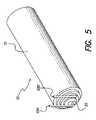
- FIG. 5is a perspective view of the battery and connecting wires
- FIG. 6is a block diagram representing the battery states based on measured battery voltage
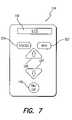
- FIG. 7is a front view of a representative remote control panel showing exemplary front panel components
- FIG. 8is an exploded view of the internal components of the BPB device
- FIG. 9is a perspective top view of the internal electronic panel in a batch configuration
- FIG. 10is a perspective top view of the panel shown in FIG. 9 with the integrated circuitry attached;
- FIG. 11Ais a perspective top view of the panel shown in FIG. 9 with the integrated circuitry shown in FIG. 10 and with the top capacitors and diodes attached;
- FIG. 11Bis an enlarged detailed view of a portion of FIG. 11A , showing in greater detail the attachment of the top capacitors and diodes;
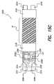
- FIG. 12is a perspective top view of the panel shown in FIG. 9 with the integrated circuitry shown in FIG. 10 , the top capacitors and diodes shown in FIG. 11A , and with the top ferrite half attached;
- FIG. 13is an enlarged detail view of the assembled components shown in FIG. 12 depicting the connecting electrical wires;
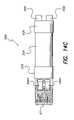
- FIG. 14Ais a perspective top view of a sub-assembly assembled during the manufacturing operation
- FIG. 14Bis a bottom perspective view of the sub-assembly shown in FIG. 14A ;
- FIG. 14Cis a top plan view of the sub-assembly shown in FIG. 14A ;
- FIG. 14Dis a bottom plan view of the sub-assembly shown in FIG. 14A ;
- FIG. 15Ais a perspective top view of the sub-assembly shown in FIG. 14A with a coil wound on the middle section of the ferrite cylinder;
- FIG. 15Bis a cross-section view of the sub-assembly shown in FIG. 15A taken along line 15 B— 15 B;
- FIG. 15Cis a top view of the sub-assembly shown in FIG. 14A with the coil ends depicted;
- FIG. 16is an enlarged detail perspective view of the sub-assembly shown in FIG. 15A placed in a soldering fixture;
- FIG. 17is an exploded view of carrier fixture plates
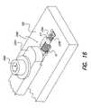
- FIG. 18is a perspective view of a supporting work-plate with one of the carrier plates shown in FIG. 17 and the sub-assembly shown in FIG. 15A ;
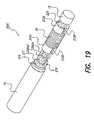
- FIG. 19is a perspective view of the sub-assembly shown in FIG. 15A with a battery attached and also depicting assembled internal components of a BPB device of the present invention
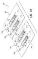
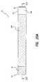
- FIG. 20Ais a top view of a BPB device of the present invention showing external coatings
- FIG. 20Bis a cross-sectional view taken along line 20 B— 20 B shown in FIG. 20A ;
- FIG. 20Cis an end view of the BPB device shown in FIG. 20A ;
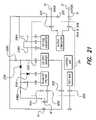
- FIG. 21is an exemplary circuit block diagram showing the main implantable components and their interactions of one embodiment of the invention.
- FIG. 22schematically illustrates a bi-directional telemetry system used with the invention
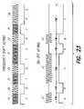
- FIG. 23depicts Frequency-Shift-Keying (FSK) and On-Off-Keying (OOK) modulation techniques used by the bi-directional telemetry system;
- FIG. 24shows a block diagram of a receiver that may be used in an external device, e.g., a remote control unit, used with the implantable microstimulator; and
- FIG. 25depicts a block diagram of a representative FSK receiver/transmitter that may be used within the implantable microstimulator.
- a fully assembled battery-powered microstimulator(also referred to as a BION® microstimulator, or battery-powered BION (“BPB” device) made in accordance with the present invention may operate independently, or in a coordinated manner with other implanted devices, or with external devices.
- BION® microstimulatoralso referred to as a BION® microstimulator, or battery-powered BION (“BPB” device) made in accordance with the present invention may operate independently, or in a coordinated manner with other implanted devices, or with external devices.
- the BPB deviceis a pulse generator which includes an internal power source. Regardless of whether the internal power source comprises a primary battery, a rechargeable battery, or an alternative power source as described below, the device containing the internal power source will be referred to as a BPB device for purposes of the present invention.
- the power sourcecomprises a rechargeable battery.
- the batteryis recharged, as required, from an external battery charging system, typically through an inductive link.
- the power sourcecomprises a primary battery.
- a primary battery, or primary battery celloffers the advantage of typically having five to ten times more energy density than does a rechargeable battery. Further, a primary battery typically exhibits a much lower self-leakage than does a rechargeable battery.
- the power source of the BPB devicecomprises an alternative energy source, or a combination of alternative energy sources.
- One such alternative energy sourceis a super capacitor.
- a super capacitortypically has ten times less energy density than does a rechargeable battery, but it can be recharged very quickly, thus allowing for the use of a simple combination RC and charger system.
- power coupled inductively to a super capacitor storage elementmay enable pulsed radio frequency (RF) power to be used, rather than continuous RF power.
- RFradio frequency
- a super capacitoris typically used, most advantageously, in combination with another power source, such as a primary battery or a rechargeable battery. The super capacitor may be charged rapidly, and then the charge stored on the super capacitor is available to supplement operation of the BPB device, either directly (to assist with higher energy stimulation levels or power requirements), or indirectly (to help recharge the battery).
- a further alternative energy source that may be used with the BPB device of the inventionis a nuclear battery, also known as an atomic battery.
- a nuclear batteryalso known as an atomic battery.
- MEMSmicro-electro-mechanical system
- Still another alternative energy source that may be used with the BPB deviceis a mechanical resonator.
- Generating power from mechanical resonators and normal human movementhas long been practiced in the art, e.g., with wrist-watches, and MEMS versions of such resonators have been around for a number of years.
- MEMS mechanical resonatorshas never been applied to implantable devices, such as the BPB device of the present invention.
- a further alternative energy source for use with a BPB deviceis an infrared collector, or infrared (solar) power source. Because the skin and body tissue is relatively transparent to red and infrared light, it is possible, e.g., through the use of an implanted silicon photovoltaic cell, to collect sufficient energy to power the BPB device from an external infrared source, such as the sun.
- thermal difference enginesbased on memory shape alloys have been demonstrated to be very efficient engines capable of generating power with minimal temperature differences.
- an internal energy sourceis provided that derives its energy from a small temperature difference, e.g., the temperature difference between the surface of the skin and a location 2–3 cm deeper inside the body.
- Still another alternative energy sourceis a flexural powered energy source.
- the BPB devicehas the general shape of a long thin rod. Hence, by placing a flexible section in the middle of the device, such section will be subjected to flexural forces. Such flexural forces, when applied to a suitable piezoelectric element coupled to the flexible section, will generate piezoelectric bimorphs which may be used to generate a voltage (power). Such technique has been used to generate power from wind.
- Another alternative energy sourceis a bioenergy power source.
- a bioenergy power sourcea chemical reactor interacts with constituents to produce mechanical or electrical power.
- a fuel cellrepresents another type of alternative energy source that may be used with the BPB device.
- a fuel cellin principle, operates much like a battery. Unlike a battery, however, a fuel cell does not run down or require recharging. Rather, it produces energy in the form of electricity and heat as long as fuel is supplied.
- a fuel cell systemwhich includes a “fuel reformer” can utilize the hydrogen from any hydrocarbon fuel.
- fuel cell technologiesmay be used with the BPB device of the present invention, such as Phosphoric Acid, Proton Exchange Membrane or Solid Polymer, Molten Carbonate, Solid Oxide, Alkaline, Direct Methanol, Regenerative, Zinc Air, or Protonic Ceramic. Such fuel cells may be designed for a single use, or refillable.
- an additional alternative energy sourcethat may be used with the BPB device is a bioelectrical cell.
- a bioelectrical cella set of electrodes (two or more) is implanted in the body tissue. These electrodes sense and use tissue generated potentials and currents in order to power the BPB device. Tissue such as cardiac muscle, cardiac conducting cells and neural tissue are examples of tissue that generates electrical potentials and currents.
- specialized biological tissuemay be implanted to provide the energy. The implanted biological tissue remains alive due to the environment provided by the body where it is implanted.
- a further alternative energy source that may be used with the BPB device of the present inventionis an osmotic pressure pump.
- Osmotic pressure pumpsmay be used to generate mechanical energy due to water, or other fluid, ingress. This mechanical energy may then be used to generate other forms of energy, such as electrical energy.
- osmotic pressuremay be used to separate the plates of a capacitor. As the plates of the capacitor separate with a given amount of charge due to osmotic pressure, the energy stored in that capacitor is incremented.
- the power source used within the BPB deviceis described as a rechargeable battery.
- the “power source” used within the BPB devicemay take many forms, including a primary battery or the alternative power sources enumerated above, and that when the term “battery” or “power source” is used herein, such terms, unless otherwise indicated, are meant to broadly convey a source of energy or power contained within, or coupled to, the BPB device.
- the BPB deviceis a fully integrated, programmable, autonomous microstimulator.
- the key features of the BPB deviceare that: (1) it is fully integrated, i.e., the BPB device is self contained (electrodes, power source, single channel stimulator), and no attachments are needed; (2) it is programmable, i.e., external devices, such as a remote control, base station, or clinician's programmer, may command the BPB device to perform different functions, such as stimulation, communication, or state; (3) it is autonomous, i.e., the BPB device may operate independently; and (4) it is small—micro-sized small, having typical dimensions that are 27 mm long, 3.3 mm diameter, and wieghing only about 0.7 grams.
- the BPB devicepreferably has a substantially cylindrical shape, although other shapes are possible, and at least portions of the BPB device are hermetically sealed.
- the BPB deviceincludes a processor and other electronic circuitry that allow it to generate stimulus pulses that are applied to a patient through electrodes in accordance with a program that may be stored, if necessary or desired, in programmable memory.
- the BPB device circuitry, power source capacity, cycle life, hermeticity, and longevityprovide implant operation at typical settings for a long time, e.g., at least five years.
- Battery (or power source) control circuitryprotects the battery or other power source from overcharging, if recharging is needed, and operates the BPB device in a safe mode upon energy depletion, and avoids any potentially endangering failure modes, with a zero tolerance for unsafe failure or operational modes.
- the BPB deviceaccepts programming only from compatible programming devices.
- An implantable BPB system made in accordance with the present inventiontypically includes internal and external components, as well as surgical components, as shown in FIG. 1 .
- the internal components 10 ′are implanted in the target tissue area of the patient and the external components 20 are used to recharge or replenish (when recharge or replenishment is needed) and communicate with the internal components.
- the components shown in FIG. 1represent as a whole an implantable BION® microstimulator system 100 . It should be noted that the present invention is not directed to a specific method for treating a disorder, but rather describes possible BPB configurations, methods of manufacture, and how the implantable BPB system functions in conjunction with the components shown in FIG. 1 .
- FIG. 1A block diagram that illustrates the various components of the BPB system 100 is depicted in FIG. 1 . These components may be subdivided into three broad categories: (1) implantable components 10 ′, (2) external components 20 , and (3) surgical components 30 .
- the BPB device 10includes a case 12 ; battery 16 ; BPB electronic subassembly 14 , which includes BPB coil 18 and a stimulating capacitor C STIM 15 ; indifferent/reference electrode 24 ; and active/stimulating electrode 22 .
- the block diagram shown in FIG. 21also shows the main implantable components of the BPB device 10 and their interactions.
- the external components 20shown in FIG. 1 include charging system 39 , which consists of the chair pad 32 and the base station 50 ; a remote control 40 ; and a clinician's programmer 60 .
- the chair pad 32has a recharger coil 34 which is electrically connected to (or may be part of) the base station 50 with extension 36 and communicates with the BPB electronic subassembly 14 with a bidirectional telemetry link 48 .
- the base station 50has an external medical grade AC adapter which receives AC power 52 through extension 54 .
- the remote control 40sends and receives communication from/to the base station 50 through Infrared Data Association, IrDA interface 42 .
- IrDA interface 42Infrared Data Association
- the remote control 40also communicates with the clinician's programmer 60 through an IrDA interface 44 and communicates with the BPB electronic subassembly 14 with an RF telemetry antenna 46 through the bidirectional telemetry link 48 .
- the clinician's programmer 60may also communicate with the BPB electronic subassembly 14 through the bidirectional telemetry link 48 .
- the base station 50also communicates with the clinician's programmer 60 through an IrDA interface 45 .
- the bidirectional telemetry link 48is also known as the FSK (Frequency Shift Key) telemetry link, or RF telemetry link.
- the charging system 39has a forward telemetry link 38 .
- Such linkmay use OOK-PWM (On/Off Keying—Pulse Width Modulation), and is typically an inductive telemetry link. When used, both power and information may be transferred to the BPB device through the OOK-PWM link. When charging is not needed, e.g., when the battery comprises a primary battery, such an inductive link may still be used to transfer information and data to the BPB device.
- OOK-PWMOn/Off Keying—Pulse Width Modulation
- the OOK-PWM link 38provides a second means for communicating with the BPB device 10 , where the first means comprises the FSK link 48 . Having two separate communication channels in this manner adds an additional safety feature to the Bion system.
- One preferred telemetry systemthat may be used with the BPB device is described more fully below.
- the surgical components 30 illustrated in FIG. 1include the BPB implant tools 62 and an external neurostimulator 64 .
- the implantable BPB device 10is inserted through the patient's tissue through the use of appropriate surgical tools, and in particular, through the use of tunneling tools, as are known in the art, or as are specially developed for purposes of implantable BPB stimulation systems.
- FIG. 1represents the BPB system 100 as a block diagram which aids in simplifying each of the described implantable components 10 ′, external components 20 , and surgical components 30 .
- FIG. 1represents the BPB system 100 as a block diagram which aids in simplifying each of the described implantable components 10 ′, external components 20 , and surgical components 30 .
- a better understanding of the possible functions associated with every element of the internal components 10 ′, external components 30 , and surgical components 30is provided in the details that follow.
- FIG. 2an exemplary waveform is shown that illustrates some of the BPB biphasic electric current stimulation parameters. Other parameters not shown include burst, ramp, and duty cycles.
- the BPB device 10may produce, for instance, an asymmetric biphasic constant-current charge-balanced stimulation pulse, as shown in FIG. 2 . Charge-balancing of the current flow through the body tissue in both directions is important to prevent damage to the tissue which results from continued preponderance of current flow in one direction.
- the first phase of the stimulation pulseis cathodic and the second phase (recharge phase) utilizes an anodic charge recovery to facilitate a charge balance.
- the stimulation phase current amplitude 66is programmable from 0.0 to about 10 mA, for instance, in 0.2 mA increments. To prevent patient discomfort due to rapidly increasing or decreasing amplitudes in the first phase of the waveform (of stimulation amplitude 66 ), changes in amplitude occur smoothly over a transition period programmable by adjusting the allowed slope (step size increments) of the amplitude through continuous pulses.
- the stimulation capability of the BPB device 10is depicted by the stimulation parameters specified in the table shown in FIG. 3 . These parameters may be achieved by the electronic subassembly 14 , battery (or other power source) 16 , and electrodes 22 and 24 .
- the stimulating electrode 22is coupled to the electronic subassembly 14 with a stimulating capacitor C STIM 15 . Net DC charge transferred during stimulation is prevented by the capacitive coupling provided by the stimulating capacitor 15 , between the BPB electronic subassembly 14 and the stimulation electrode 22 .
- the BPB stimulation electrode 22has a cathodic polarity with associated negative current amplitude, and the reference electrode 24 is the anode.
- Each BPB device 10has an identification code used to uniquely identify the device.
- the identification codeallows each unit to act on particular messages containing its unique identification code.
- Each BPB device 10also responds to universal identification codes used for cases in which the unique address is unknown by the external device, the unique address has been corrupted, or when a command is sent to multiple BPB units.
- the BPB device 10receives commands and data from the remote control 40 , clinician's programmer 60 , and/or charging system 39 via FSK (frequency shift keying) telemetry link 48 .
- the range of the FSK telemetry link 48is no less than 30 cm in an optimal orientation. Factors that may affect the range of the FSK telemetry link 48 include an impaired BPB device, depleted external device, insufficient power, environmental noise, and other factors, e.g., the surroundings.
- the maximum response time for the FSK telemetry link 48is less than 2 seconds, under normal operating conditions.
- the OOK (On-Off Keying) telemetry link 38allows commands and data to be sent by the charging system 39 to the BPB device 10 .
- the range of the OOK telemetry link 38is ideally no less than 15 cm in any orientation and no less than 15 cm in an optimal orientation.
- the OOK telemetry link 38allows the charging system 39 to communicate with the BPB device 10 even when the BPB device 10 is not actively listening for a telemetry signal, e.g., when the BPB device 10 is in the Hibernation State or the Storage State (states for the BPB device which will be discussed in detail below).
- the OOK-PWM telemetry link 38also provides a communication interface in an emergency situation, e.g., an emergency shutdown.
- Reverse telemetryis also available through the FSK telemetry link 48 .
- the reverse FSK telemetry link 48allows information to be reported by the BPB device 10 to the clinician's programmer 60 , the remote control 40 , and/or the charging system 39 .
- the range of the reverse telemetry link 48is no less than 30 cm in an optimal orientation.
- the type of information transmitted from the BPB device 10 to the clinician's programmer 60 , remote control 40 , and/or charging system 39may include but is not limited to battery voltage, BPB internal register settings, and acknowledgments.
- the FSK telemetry systemin one preferred embodiment, operates in the frequency band of 127 KHz ⁇ 8 KHz.
- a valid (i.e. non-error containing) messagean acknowledgment is transmitted.
- FIGS. 22–25a more detailed description of one preferred implementation of an FSK telemetry link is shown.
- a BPB device 10(a very small device) is implanted in a patient.
- the implant depthmay be several centimeters, so it is important that a telemetry link be capable of functioning over a sufficient distance, e.g., at least 15 cm, and preferably at least 30 cm or more, e.g., 60 cm.
- the remote control 40 and the chair pad 32(which is connected to a base station 50 (see FIG. 1 ) incorporates appropriate antenna coils and transmitting circuitry for sending FSK signal transmissions to the BPB device 10 .
- the BPB device 10includes an FSK receiver circuit, described more fully below, that allows it to receive the FSK transmissions 48 ′ and 48 ′′.
- the BPB device 10includes a transmitter that allows it to send FSK signal transmissions 48 A and 48 B to the remote control 40 and chair pad 32 , respectively.
- a separate OOK-PWM communication linkthat allows communication signals to be sent from the chair pad 32 , i.e., from the base station 50 , which is connected to the chair pad (see FIG. 1 ) to the BPB device 10 .
- FIG. 23depicts the two types of modulation that are used with the communication links 48 and 38 of the present invention.
- the primary type of communication usedis frequency shift keying, illustrated in the top portion of FIG. 23 , wherein the frequency of the transmitted signal varies between two frequencies, F 1 and F 2 .
- a binary data “1”is represented by the first frequency F 1
- a binary “0”is represented by the second frequency F 2 .
- the bottom portion of FIG. 23illustrates an On-Off Keying (OOK)-PWM (pulse width modulation) approach, wherein the transmitted signal comprises either a first frequency F 1 ′ or no transmitted signal (frequency equals zero) for one of two pulse widths, PW 1 or PW 2 .
- OOKOn-Off Keying
- PWMpulse width modulation
- a change from the F 1 ′ frequency to the zero (off) frequencyis used to indicate a data transition from one bit to the next bit in the data stream.
- the transmitted signalhas a frequency F 1 ′ for a width of PW 1 , indicating a binary “0”, followed by a transmitted signal being off (frequency is zero) for a width of PW 1 , indicating another binary “0”; followed by a transmitted signal of frequency F 1 ′ for a pulse width of PW 2 , indicating a binary “1”; followed by a transmitted signal of frequency zero (signal off) for a width of PW 1 , indicating a binary “0”; followed by a transmitted signal of frequency F 1 ′ for a width PW 1 , indicating a binary “0”; followed by a transmitted signal of frequency zero (signal off) for a width PW 2 , indicating a binary “1”.
- the binary data stream being transmitted in the exemplary signal shown in the bottom of FIG. 23comprises “001001”
- FIG. 24illustrates a representative type of FM receiver that may be implemented in the remote control 40 , or the base station 50 and chair pad 32 , in order to receive the FSK signal transmitted from the BPB device 10 .
- such receiverincludes an antenna 502 for receiving the FSK signal transmitted from the BSP device 10 .
- This signalis then amplified by a pre-amplifier 504 having a gain of about 20 dB.
- the amplified signalis then mixed in a mixer 506 with a signal obtained from a local oscillator (LO) 507 , reduced by a dividing circuit 508 , to produce an intermediate frequency (IF) signal.
- LOlocal oscillator
- the LO frequencyis 656 KHz, and is divided by the dividing circuit 508 by two, thereby providing a signal of 323 KHz that is mixed with the incoming FSK signal from the BPB device 10 .
- the loss associated with the conversion to the IF frequencyis only about 10 dB.
- the IF frequency signalis passed through a bandpass filter 510 and then amplified by amplifier 512 , which amplifier has a gain of about 40 dB.
- the amplified IF signalis then passed through another bandpass filter 514 .
- the center frequency of the bandpass filters 510 and 514is, in one embodiment, about 455 KHz, and the bandwidth is about 12 Khz.
- the amplified and filtered IF signalis then subjected to a limiting amplifier 516 , having a gain of about 80 dB, and the resulting signal is then passed through a demodulator circuit 518 .
- the demodulator circuit 518demodulates the FSK data contained in the IF signal to recover the data therein. As depicted in FIG.
- the demodulator circuit 518includes a quad coil tuned to 455 KHz, a discriminator (multiplier) circuit 522 , and a low pass filter 524 .
- the output from the low pass filter 524is an analog data stream wherein a “1” is represented by a first amplitude, e.g., +V volts, and a “0” is represented by a second amplitude, e.g., 0 volts.
- the remote control receiver circuit depicted in FIG. 24is a typical FM receiver, not much different from the FM receiver included in a car radio.
- Such receiveris inexpensive to make from readily available parts, is easy to manufacture and test, and uses a reliable and proven architecture.
- This circuitprovides direct conversion of the incoming FSK signal to data, and as such represents a relatively new approach in wireless technology.
- the circuitdoes not require large external components.
- the circuituses a BFSK (binary frequency shift key) modulation scheme wherein a “0” is represented by a lower frequency F 2 , and a “1” is represented by a higher frequency F 1 .
- F 1is 131 KHz
- F 2is 123 KHz. Thus, there is not much frequency difference between F 1 and F 2 .
- the frequency differenceis only 8 KHz, which is only about a 6.3% difference between the F 1 and F 2 frequencies (where the percent difference is calculated as ⁇ (F 1 ⁇ F 2 )/[(F 1 +F 2 )/2] ⁇ 100).
- F 1 and F 2 so close to each other in frequencygreatly simplifies some of the antenna tuning issues that are present within the BPB device.
- having F 1 and F 2 so close to each other in frequencyalso means that great care must be exercised to precisely calibrate the local oscillator so that the BPB electronic circuitry can successfully distinguish between 123 KHz and 131 KHz. Such calibration should occur at body temperature, i.e., about 37° C.
- incoming BFSK signal 48 ′ or 48 ′′is received through an antenna coil that is wrapped around ferrite core 212 .
- a tuning capacitor 532tunes the coil 18 , in combination with the ferrite core 212 , so that it optimally receives signals in the 123 KHz to 131 KHz range.
- a data switch 534is switched to a first position so that the incoming tuned signal is applied to a mixer circuit 536 .
- a 4 MHz oscillatorproduces a 4 MHz signal that is divided by 2048 in dividing circuit 540 to produce a 1.985 KHz clock signal.
- the 4 MHz signalis similarly divided by 32 in dividing circuit 542 to produce a local oscillator signal having a frequency F 3 that is also applied to the mixer circuit 536 .
- the local oscillator frequency F 3is 127 KHz, mid-way between the F 1 and F 2 frequencies.
- the mixer (or multiplier) circuit 536multiplies the incoming signal with the 127 KHz local oscillator signal to produce a difference signal, F 3 ⁇ F 2 (when the incoming signal is F 2 ), and F 3 ⁇ F 1 when the incoming signal is F 1 ).
- the sum F 3 +F 2 or F 3 +F 1is filtered out.
- the signals that remainare F 3 ⁇ F 2 and F 3 ⁇ F 1 .
- F 3 ⁇ F 2is 4 KHz
- F 3 ⁇ F 1is ⁇ 4 KHz (or 0 KHz because negative frequencies don't exist in real time).
- this difference signalis 4 KHz if the incoming signal is 123 KHz (a binary “0”), and will be 0 KHz if the incoming signal is a binary “1”.
- the resulting signal(4 KHz or 0 KHz) is applied directly to the digital processor 544 used within the electronic subassembly 14 of the BPB device 10 .
- the processor 544is able to readily ascertain whether such signal is a 4 KHz signal or a 0 KHz signal, and is therefore able to readily assign a “1” or “0” value to the data bit signal.
- One technique that may be used to readily distinguish a 4 KHz signal from a 0 KHz signal within a digital processoris to apply the signal as a clock signal to a register that is hard-wired to fill with “1's” as it is clocked.
- a prescribed period of timee.g., a data clock time, or the duration of a data bit, or a portion of a data bit
- the contents of the registerare checked, and if a high value, then a determination is made that the incoming data bit must be a “1”, and if a low value, then a determination is made that the incoming data bit must be a “0”.
- the data switch 534When used as a transmitter, the data switch 534 is switched to a second position that allows data to be transmitted from the antenna coil 18 as data 48 A or 48 B. Data to be transmitted is received on Tx Data line 545 and is converted to either a 123 KHz signal (to represent a binary “0”), or to a 131 KHz signal (to represent a binary “1”). Such conversion to BFSK data is done with the help of the 4 MHz oscillator signal and a divide-by ⁇ 31 or ⁇ 33 circuit 546 .
- the OOK-PWM receiving circuit used within the BPB devicemay use the same antenna coil 18 as does the BFSK circuit.
- the coil 18and many of its related components, serves multiple functions using the principles described, e.g., in U.S. patent application Ser. No. 09/799,467, filed Mar. 5, 2001; and Ser. No. 10/133,766, filed Apr. 26, 2002 both of which applications are assigned to the same assignee as is the present application, and both of which applications are incorporated herein by reference.
- the OOK-PWM transmitter circuit used within the base station 50 and charging pad 32may be of conventional design.
- the receiver and transmitter circuit used within the BPB device 10offers the following features and advantages: (1) it is able to receive and send data across body/air reliably; (2) it is simple, having only a few components; (3) it works well after initial calibration; (4) it requires only one external coil and capacitor, may be fabricated in a small space, and consumes very little power; (5) it has an approximate range of 60 cm; (6) it has a response time of less than 2 seconds; (7) it experiences a minium number of errors, e.g., on the order of 1 command error per year for every 10,000 users; and (8) for safety and other technical reasons, a backup or second telemetry system is included for getting data into the BPB device.
- BPB case 12a side view of the BPB case 12 is shown depicting exemplary overall dimensions for the case 12 and BPB internal components.
- the BPB case 12functions together with the additional components of BPB device 10 , including the BPB battery 16 and the BPB electronic subassembly 14 , to provide the stimulating function of the device.
- BPB case 12may have a tubular or cylindrical shape with an outer diameter shown in FIG. 4 as D 1 having a minimum value of about 3.20 mm and a maximum value of 3.7 mm, and preferably a maximum value of about 3.30 mm.
- the inner diameter of the portion of the BPB case 12 enclosing the electronic subassembly 14is shown in FIG.
- the inner diameter of the portion of the BPB case 12 enclosing the BPB battery 16is shown in FIG. 4 as D 3 with a minimum value of about 2.92 mm and a maximum value of about 3.05 mm.
- the length of the BPB case 12is shown in FIG. 4 as L 1 with and is no greater than about 30 mm, and preferably no greater than about 27 mm (L 1 includes the length of the case housing plus the stimulating electrode 22 ).
- the length L 2 of the case 12has a value of about 24.5 mm.
- the portion of the case 12 enclosing the electronic subassembly 14is shown in FIG.
- the BPB deviceinstead of being cylindrically shaped, may have a rectangular or oval cross section having a width and height that is no greater than about 3.3 mm, and an overall length is no greater than about 27 mm.
- the case 12 of the BPB device 10is hermetically sealed.
- the case 12may be made of metal (e.g., titanium), which material is advantageously biocompatible.
- the BPB case 12is preferably, but not necessarily, Magnetic Resonance Imaging (MRI) compatible. The manufacturing/assembly process of the BPB device 10 will be discussed in detail below.
- MRIMagnetic Resonance Imaging
- the BPB device 10includes a battery 16 .
- the battery 16may be a primary battery, a rechargeable battery, or other power source, as previously described.
- the BPB device 10includes a processor and other electronic circuitry that allow it to generate stimulating pulses that are applied to a patient through electrodes 22 and 24 in accordance with a program stored in programmable memory located within the electronic subassembly 14 .
- the processor and other electronic circuitryalso provide the telemetry functions described herein.
- the battery 16 shown in FIG. 5is a self-contained battery which powers the BPB device 10 .
- the battery 16may be a Lithium-ion battery or other suitable type of battery or power source.
- One type of rechargeable battery that may be usedis disclosed in International Publication WO 01/82398 A1, published 01 Nov. 2001, and/or WO 03/005465 A1, published 16 Jan. 2003, which publications are incorporated herein by reference.
- Other battery construction techniquesthat may be used to make the battery 16 used with the BPB device are as taught, e.g., in U.S. Pat. Nos. 6,280,873; 6,458,171 and U.S. Publications 2001/0046625 A1 and U.S.
- Rechargingoccurs from an external charger to an implant depth, e.g., up to 13.87 cm. At this distance, charging from 10% to 90% capacity can occur in no more than eight hours.
- the battery 16functions together with the additional components of the BPB device 10 , including the BPB case 12 and the BPB electronic subassembly 14 to provide electrical stimulation through the electrodes 22 and 24 .
- the battery or power source 16has a pin 95 protruding from the flat end for the positive polarity contact. This pin has a protruding length, e.g., of 0.25 mm and is embedded internally throughout the length of the cathode case of the battery 16 .
- the pin 95may be made of platinum or other suitable anode material.
- Wires 68 A and 68 Bare used for connecting the battery 16 to the electronic subassembly 14 .
- Wire 68 Ais insulated and laser welded or otherwise electrically connected to the pin 95
- wire 68 Bis not insulated and is laser welded or otherwise electrically connected to the case of the battery.
- the battery case 70has a negative polarity.
- the battery's nominal voltageis typically 3.6 V, measured during a first cycle C/5 discharge.
- the battery's nominal capacity, Cis no less than 2.5 mAh (milli-amp-hours) when measured after the third discharge cycle with C/2 charge to 4.0V and C/5 discharge to 3.0V at 37° C.
- Charge or discharge timeis calculated by taking the capacity (mAh or Ah) and dividing it by current (mA or A). The nominal settings are 4 mA amplitude, 20 Hz pulse frequency, 200 ⁇ sec pulse width, 5 sec burst-on, 5 sec burst-off, and 200 ⁇ A recovery into a 1000 ⁇ resistive load.
- the electronic subassembly 14functions together with the additional components of the BPB device 10 , including the BPB case 12 , BPB battery 16 , and electrodes 22 and 24 , to provide the BPB device stimulating function.
- the electronic subassembly 14fits within, for instance, a cylinder with an outer diameter D 2 and length L 3 as shown in FIG. 4 .
- the inner diameter D 2has a minimum value of about 2.40 mm and a maximum value of about 2.54 mm.
- the length L 3has a maximum value of about 13.00 mm.
- the electronic subassembly 14contains circuitry for stimulation, battery charging (when needed), telemetry, production testing, and behavioral control.
- the stimulation circuitrycan be further divided into components for high voltage generation, stimulation phase current control, recovery phase current control, charge balance control, and over voltage protection circuitry.
- the telemetry circuitrycan be further divided into an OOK receiver, FSK receiver, and FSK transmitter.
- the behavioral control circuitrycan be further divided into components for stimulation timing, high voltage generation closed loop control, telemetry packet handling, and battery management.
- the coil 18(shown in FIG. 1 ) is utilized for receiving power for battery charging (when used), telemetry, and high voltage generation.
- the charging circuitry within the electronic subassembly 14detects the presence of an external charging field within no more than 5 seconds of the application of such a field. Upon detection, the BPB device 10 enables a mode in which it can receive a telemetry message and in which it can recharge the battery 16 , as necessary.
- the electronic subassembly 14measures the rectified voltage during recharging and is able to transmit the measured voltage value to the base station 50 via coil 34 .
- the battery voltage measurementsare made in relatively identical conditions. Specifically, the battery voltage is measured when no stimulation pulse is being delivered.
- the BPB device 10When the BPB device utilizes a rechargeable battery, and when the voltage is less than the voltage defined by the Battery Recharge Upper Voltage Limit Internal Register (BRUVLIR), the BPB device 10 charges the battery 16 using constant current charging with a maximum current of C/2. The constant current phase of charging ends and the constant voltage phase of charging begins when the BPB voltage reaches the voltage defined by the BRUVLIR.
- BRUVLIRBattery Recharge Upper Voltage Limit Internal Register
- the charging circuitrymaintains the battery 16 charging voltage at the voltage defined by the BRUVLIR.
- the charge ready bit of the BPB status registeris activated and charging may be completed by the removal of the magnetic field.
- the BPB charging circuitrymonitors the incoming magnetic energy and periodically sends information to the base station 50 via coil 34 in order to minimize the magnetic field that the BPB device 10 is exposed to, thus minimizing the electrical dissipation of the BPB device 10 while charging.
- U.S. Pat. No. 6,553,263, incorporated herein by referencedescribes relevant charging technology which may also be used.
- Protection circuitry within the electronic subassembly 14is used as a failsafe against battery over-voltage.
- a battery protection circuitcontinuously monitors the battery's voltage and electrically disconnects the battery if its voltage exceeds 4.1 V.
- the BPB device 10is not able to recover from an excessive voltage condition, and thus requires explantation should an over-voltage condition occur, where an over-voltage condition is defined as a voltage that exceeds 4.1 V.
- the BPB device 10has different states based on the measured battery voltage, Vbatt. (Vbatt is measured when no stimulation is being delivered). FIG. 6 represents these various states and transitions between states.
- the BPB device 10should normally be in Normal Operation State 102 , but when the measured battery voltage, Vbatt, falls below the voltage defined by the battery voltage hibernation level internal register, VHIB, the device enters a low-power Hibernation State 104 .
- VHIBis a programmable voltage value of hibernation threshold for the battery 16 .
- stimulation and FSK telemetryare discontinued. In other words, the BPB device 10 discontinues listening for an incoming FSK telemetry signal but continues to listen for an incoming OOK telemetry signal.
- the BPB device 10is able to detect an applied external charging field.
- the Hibernation State 104persists until the battery voltage, Vbatt, exceeds the programmable value of VHIB, where VHIB is programable between 3.25 V and 3.6 V.
- Vbattthe battery voltage
- VHIBis programable between 3.25 V and 3.6 V.
- the battery 16then goes back to Normal Operation State 102 and the stimulation and FSK telemetry signals resume when Vbatt becomes greater than the programmed value ⁇ 0.05 V.
- the battery 16may also enter the Depletion State 106 when Vbatt falls below a non-programmable voltage value of Power On Reset (VPOR) threshold for the battery 16 of between 2.2 V and 2.8V.
- VPORPower On Reset
- the stimulation and FSK telemetryare discontinued and are only able to be resumed following programming and recharging by a clinician.
- the BPB device 10disables all circuitry except what is required for recharging the battery when an RF charging field is applied. While in the Depletion State 106 , the BPB circuitry is able to recharge the battery 16 from an external charging field.
- Charging while in the Depletion State 106is performed at a slow rate (trickle charge) to allow the battery to recover from a low voltage condition.
- the BPB device 10performs a power-on reset when Vbatt exceeds VPOR, then the BPB device 10 returns back to the Hibernation State 104 .
- the BPB device 10can also be set in Storage Mode 108 .
- Storage Mode 108the BPB device 10 shuts down the circuitry in order to conserve power and the stimulation and FSK telemetry is disabled.
- Storage Mode 108the BPB device 10 is able to detect a charging field and is able to receive both power for recharging as well as OOK telemetry messages via a charging field.
- the BPB device 10contains an inductive coil 18 utilized for receiving power and telemetry messages through an inductive telemetry link 38 .
- the coil 18may also be utilized to implement additional functions, including voltage conversion.
- the BPB coil 18 contained in the electronic subassembly 14has an exemplary cylindrical shape and is constructed from multiple turns of conductive wire around a two-piece exemplary dumbbell shaped ferrite core. Assembly of the BPB coil 18 , internal electronic components, and the two-piece ferrite core will be discussed in more detail presently.
- the remote control 40provides clinician programming of the BPB device 10 and limited stimulation control for the patient following implantation via a bidirectional FSK telemetry link 48 .
- an IrDA direct link 44is provided to interface between the clinician's programmer 60 and the remote control 40 .
- the remote control 40is small and light enough to be held comfortably in one hand and fits inside a purse or pocket. Its smallest dimension is no more than 3 cm and its largest dimension is no more than 11.5 cm.
- the remote control 40operates on standard (e.g., off-the-shelf) batteries, such as AAA batteries.
- FIG. 7An exemplary front panel 114 of the remote control 40 is shown in FIG. 7 , which identifies the primary control keys.
- An LCD display 116shows all values and messages, e.g., whether stimulation is enabled or disabled or the battery's energy level or state (normal, hibernation, depletion, or storage).
- the following control keysare found in the front panel 114 : ON/OFF key 118 , up arrow key 120 , down arrow key 122 , information key 123 , and status key 124 . All control keys are easily manipulated and may be recessed so that they are not accidentally activated (e.g., when the remote control 40 is in a purse).
- the Clinician's Programmer (CP) 60controls an implanted BPB device 10 by communicating with an External Controller (the Remote Control 40 or charging system 39 ). External Controller 39 or 40 in turn conveys commands to the BPB device 10 through an FSK telemetry link 48 .
- a clinicianhas three ways to start up the CP program—“New Patient”, “Find Patient” and “Scan for BION”.
- the “New Patient” optionbrings up a blank form for the clinician to fill in the patient demographic information such as name, birth date, identifying number, address, contact information, and notes.
- the “Find Patient” optionbrings up a menu of previously entered patient records for selection. Upon selection of a patient, the saved patient information is displayed for review.
- the “Scan for BION” optiondetermines whether or not there is a BPB device 10 within telemetry range. If so, the identification number (ID) of the BPB device 10 is obtained and the database is searched for a patient whose implanted BPB device 10 ID matches the one found. If such a match is found, the patient's demographic information is automatically displayed for review.
- IDidentification number
- the cliniciancan then adjust stimulation parameters through the Parameter Test utility.
- the successful stimulation parameter setscan be saved to the patient's record in the database. Previously saved parameter sets can be reviewed and re-applied using utilities to view history or current settings. The current battery level of the BPB device 10 , as well as records of the recharge times, can be viewed.
- the Clinician's Programmer 60may also be used to generate different types of reports, such as Patient Information, Session Summary, Implant System, and Visit History.
- the Patient Information reportincludes all of the patient's demographic information.
- the Session Summary reportsummarizes the events for the followup session.
- the Implant System reportdetails the information for the implanted BPB device 10 and any external controllers assigned to the patient.
- the Visit Historyshows information about office visits for the patient in the desired date range.
- the Clinician's Programmer 60includes utilities to backup and restore the database. A utility is also available for exporting selected patient information into a data format for transfer.
- the charging system 39 shown in FIG. 1which includes the base station 50 and the chair pad 32 , is used to transcutaneously charge the BPB battery 16 (when needed), and it is also used to communicate with and control the BPB device 10 via an OOK telemetry link 38 and/or an FSK bidirectional telemetry link 48 .
- Most of the electronics of charging system 39are housed in a stand-alone package, with the exception of an AC adapter 54 for connection with a wall AC power socket 52 .
- the charging system 39also provides feedback to the user regarding the status of the BPB battery 16 during recharging.
- the remote control 40 and the clinician's programmer 60may be linked via an IrDA interface 45 to the charging system 39 to facilitate exchange of data.
- Unassembled BPB internal components 200are shown in FIG. 8 and their interactions once assembled are depicted in the functional block diagram of FIG. 21 .
- the components 200include panel 202 ; integrated circuitry 206 ; capacitors 208 A 1 , 208 A 2 , 208 B 1 , and 208 B 2 ; diodes 210 A and 210 B; two ferrite halves 212 A and 212 B; battery 16 ; stimulating capacitor 15 ; molecular sieve moisture getter material 235 ; and unwound conductive coil wire 216 .
- the components 200are encapsulated within, for instance, a hermetically-sealed housing which consists of two cylindrical shell housings, e.g., a titanum housing 213 and a ceramic housing 215 (both shown in FIG. 20B ).
- a hermetically-sealed housingwhich consists of two cylindrical shell housings, e.g., a titanum housing 213 and a ceramic housing 215 (both shown in FIG. 20B ).
- Other suitable housing material(s) and shapesmay be used.
- the BPB assembly processconsists of a series of assembly operations that, herein, are grouped into three stages.
- the first stagecomprises operations for putting together sub-assembly 200 A (shown in FIG. 14A ) and further operations to create sub-assembly 200 B (shown in FIG. 15A ) from sub-assembly 200 A and other components;
- the second stagecomprises creating sub-assembly 200 C (shown in FIG. 19 ) from sub-assembly 200 B and other components;
- the third stagecomprises a process in which the sub-assembly 200 C is encapsulated within the exemplary hermetically-sealed cylindrical housing (shown in FIG. 20A ).
- Materials used for the manufacturing/assembly processare only exemplary and other suitable materials may be used.
- the substrate panel assembly 202is a single layer, double-sided circuit board made of ceramic, organic, or other suitable flexible material(s).
- each panel 202 n of the substrate panel assembly 202may be precut and only small portions of the edges may be left attached to the substrate panel assembly 202 .
- the small portions that are left intactmake the alignment of other components and future singularization of each panel 202 n much easier, especially when all other parts have been assembled to the substrate panel assembly 202 .
- the top surface 204 of substrate panel assembly 202is used to mount other components, such as the integrated circuit 206 , which is similar in shape to each of the substrate panels 202 n.
- the top surface 204 of the substrate panel assembly 202is identified by a printed part number made during the manufacturing of the substrate panel assembly 202 .
- Each panel 202 n of substrate panel assembly 202is uniquely serialized using a laser beam.
- the serial numbersare engraved on the bottom surface 205 of the substrate panel assembly 202 , and metal pads 203 A and 203 B (shown in FIGS. 14C , 14 D, and 15 C) carry the serial number, which metal pads are used for test probing during several steps of the assembly process.
- Two ferrite half cylinders 212 A and 212 B“sandwich” a separated panel 202 n and associated integrated circuit 206 .
- This “sandwich” designmaximizes the size of the half cylinders 212 A and 212 B and the coil 18 which receive the power transfer from the external coil, thus, maximizing the magnetic inductance.
- the integrated circuit (IC) 206is a custom designed IC chip.
- the IC waferwhich includes a multitude of these custom ICs 206 , is made using standard IC manufacturing processes.
- the IC waferis then taken through a post-process called redistribution:
- a layer of polyamide (or other suitable insulation)is deposited on the IC surface.
- Photosensitive materialis deposited and exposed, e.g., through a mask, in only selected areas, as in photochemical etching processes known in the art.
- the photosensitive material and portions of the polyamideare removed, for instance, to expose the aluminum pads on the surface of the IC.
- a layer of titanium tungstenin applied in a similar manner (i.e., using photosensitive etching or the like) to the aluminum.
- a layer of copperis then deposited, and photochemical etching or the like used to remove the areas of copper that are not needed.
- This layer of copper(aided by the surrounding layers) creates the “redistribution” of mounting pads and traces that allows secondary components such as diodes 210 A and 210 B and capacitors 208 A 1 and 208 A 2 to be assembled above and bonded to the IC 206 and allows simplified interconnections between the IC 206 and the substrate 202 n, as shown in FIG. 13 .
- titanium tungsten or other suitable bonding materialis applied to select portions of the copper, where gold or other suitable conductive material will be applied.
- Another layer of polyamide or similar insulationis applied (via photochemical etching or the like) to select areas.
- a layer of gold or other conductive materialis applied (again, via photochemical etching or the like) to the bonding material that was earlier applied to the copper.
- each non-conductive epoxyis applied to attach each integrated circuit 206 as shown in FIG. 10 .
- each non-serialized IC 206is now uniquely identified by the serial number laser engraved on the backside of substrate panels 202 n, and can be tested and calibrated with calibration information saved together with the serial number.
- Conductive epoxyis applied to portions of the top surface 207 of each IC 206 to mount, e.g., ceramic, capacitors 208 A 1 and 208 A 2 , and the diodes 210 A and 210 B to their respective redistributed interconnection pads, as shown in FIG. 13 .
- Non-conductive epoxyis applied to a portion of surface 207 of the ICs 206 to attach the top ferrite half 212 A, as shown in FIG. 12 .
- Electrical wires 214are bonded, connecting traces on panel 202 n to diodes 210 A and 210 B, and connecting traces on panel 202 n to IC 206 .
- An enlarged detail view of the bonded wires 214is shown in FIG. 13 . Quality inspection can be done after this step, as well as other steps in the manufacturing process.
- the electrical wires 214may be encapsulated with an epoxy joint 217 , as shown in FIG. 14A .
- the mounting of the components on the top surface of the substrate panel 202is now complete.
- the bottom half components of the “sandwich” ferrite arrangementare assembled next to the bottom surface 205 of the substrate panel 202 n (as shown in FIG. 14B ).
- a non-conductive epoxyis applied to the portion of the bottom surface 205 used to attach the bottom ferrite half 212 B.
- a conductive epoxyis then applied to the portion of the bottom surface 205 of the substrate panel 202 n used to attach the ceramic capacitors 208 B 1 and 208 B 2 .
- FIG. 14Ashows an isometric top view of a single sub-assembly 200 A showing the wire bonds and diodes encapsulated in epoxy joint 217 .
- FIG. 14Bshows an isometric bottom view of the sub-assembly 200 A.
- FIG. 14Cshows the top plan view of the sub-assembly 200 A showing the two pads 203 A and 203 B protruding from one end of the ferrite “sandwich” arrangement. The pads 203 A and 203 B can be used for testing the assembled electrical connections.
- FIG. 14Dshows the bottom plan view of the sub-assembly 200 A where the two pads 203 A and 203 B, as well as pads 201 A, 201 B, 201 C, and 201 D are also used for electrical test probing.
- the two metal pads 203 C and 203 Dalso carry the serial number.
- the bottom of the sub-assembly 200 Ais identified by the mark 221 located on the ceramic capacitor 208 B 1 to aid in orientation and handling during manufacturing.
- the unwound coil wire 216is then wound on the middle section of the ferrite cylinder, as shown in FIG. 15A .
- the coil wire 216 in a wound configurationis referred to as the BPB coil 18 , as shown in FIGS. 1 , 15 A, and 15 B.
- the coil 18has 156 turns and is wound in two layers identified as coil layer 223 A and coil layer 223 B, as shown in FIG. 15B , which depicts a cross-section of the sub-assembly 200 B (which is the designation given to sub-assembly 200 A after it has proceeded through the coil winding process).
- One coil layer or more than two coil layersmay also be used.
- the required amount of layersdepends on the frequency, current, and voltage requirements.
- Distance A(shown in FIG. 15B ) is determined by the required number of coil turns and distance B (also shown in FIG. 15B ) is the amount of chamfer depth required to fit the number of layers.
- two layersare shown in FIG. 15B .
- Minimizing the coil layers, which minimizes the diameter of the coilallows subassembly 200 B to fit in the smallest shell possible, for which a ceramic or other suitable material can be used.
- an exemplary “dumbbell” configurationis formed with the arrangement of the two ferrite halves 212 A and 212 B in which the gap formed by the distances A and B is used to wind the coil 216 .
- a soldering fixture 226shown in FIG. 16 , is used to assist in terminating the coil ends 228 A and 228 B to pads 201 A and 201 B of the panel 202 n, as shown in FIG. 15C . Soldering the coil ends 228 A and 228 B becomes more practical when the sub-assembly 224 is isolated and secured using soldering fixture 226 or other similar soldering fixture.
- the bottom surface of the panel 202is facing up using the mark 221 to identify this surface.
- the sub-assembly 200 Bis placed in fixture 226 with its bottom side facing up and is held firmly in place by handle 226 A which is tightened by bolt 226 B.
- FIG. 16shows the sub-assembly 200 B securely loaded in soldering fixture 226 .
- the two coil ends, 228 A and 228 B,are soldered to the pads 201 A and 201 B (the ones next to the ceramic capacitors 208 B 1 and 208 B 2 located on the bottom surface of panel 202 ), as shown in FIG. 15C .
- This stepfinalizes the first assembly stage after which sub-assembly 200 B is complete.
- a carrier 230shown in FIG. 17 , has been designed to facilitate the second assembly stage and aid in alignment of components.
- the carrier 230consists of two plates, top plate 230 A and bottom plate 230 B.
- the top plate 230 Aalso contains openings 232 A, 232 B, and 232 C to allow access to the assembled components for processing, testing, and inspection.
- Two bolts 234 A and 234 B, aligned with holes 233 A and 233 B,are required to securely fasten plates 230 A and 230 B.
- Holes 233 C and 233 Dare used to secure the assembled carrier 230 on a metal work plate 239 using pins 237 A and 237 B (shown in FIG. 18 ). Having the carrier 230 secured on the work plate 239 facilitates in a smooth assembly process.
- the sub-assembly 200 B and the stimulating capacitor 15are placed in the carrier bottom plate 230 B as shown in FIG. 18 , then top plate 230 A is bolted to bottom plate 230 B with bolts 234 A and 234 B. Through groove opening 232 B on top plate 230 A, conductive epoxy 229 is applied to bond the gold-coated nickel ribbon attached to one end of the capacitor 15 to bond to pads 203 A and/or 203 B (seen best in FIGS. 14C and 14D ). At this point, while in the carrier 230 , the assembly is tested (as it is throughout the manufacturing process) and is also processed through baking temperature cycling.
- top carrier plate 230 Ais removed, the battery 16 is securely placed in the carrier groove 231 C of bottom plate 230 B, then top plate 230 A is bolted back in place.
- the battery 16has two nickle wires 68 A and 68 B (shown in FIG. 5 ) which have been pre-welded. Battery 16 is placed into groove 231 C so the nickle wires 68 A and 68 B protrude towards the bottom surface 205 of the substrate panel 202 n. Using groove opening 232 B, where the nickle wires 68 A and 68 B of the battery 16 and the assembly 200 B come together, an amount of non-conductive epoxy 219 is applied so that the ends of wires 68 A and 68 B are still accessible.
- the nickle wires 68 A and 68 Bare bent towards and soldered to the substrate pads 201 C and 201 D. Additional non-conductive epoxy 219 is applied to secure the connection between the soldered nickle wires 68 A and 68 B and pads 201 C and 201 D. This finalizes the second assembly stage when the sub-assembly 200 C as shown in FIG. 19 is complete.
- the assembly 200 Cis encapsulated within an exemplary hermetically-sealed housing which consists of, for instance, two cylindrical cases, a titanum 6/4 case 213 and a zirconia ceramic case 215 , as best seen in the cross sectional view FIG. 20B .
- Alternative materials and shapes for the housingmay also be used.
- a titanium 6/4 or other suitable connector 236is brazed with a titanium nickle alloy (or other suitable material) to the ceramic case 215 for securing the mating end of the titanium case 213 .
- the connector 236has an inside flange 236 A and an outside flange 236 B which serve to “self center” the braze assembly.
- conductive silicone adhesive 238is applied to the inside end of the ceramic shell as well as to the inside end of the titanium shell.
- a molecular sieve moisture getter material 235is also added to areas 235 A, 235 B, and 235 C as shown in FIG. 20B before the brazing process.
- the “spiral” self centering button electrode 22is made from titanium 6/4 or other suitable material and is plated with an iridium coating or other suitable conductive coating. An end view of electrode 22 is shown in FIG. 20C .
- a spiral groove 324is made to stimulating surface 322 of the electrode 22 .
- the spiral groove 324is just one example of groove shapes that may be used; other shapes, such as a cross hatch pattern or other pattern may also/instead be used. Groove 324 increases the conductive surface area 322 of electrode 22 .
- the sharp edges in groove 324force a more homogeneous current distribution over the surface 322 and decrease the chances of electrode corrosion over time.
- the corrosion effect which may affect the electrode 22is also known as biofouling, which is the gradual accumulation of bacteria on the surface of the electrode 22 once immersed in body fluid.
- biofoulingwhich is the gradual accumulation of bacteria on the surface of the electrode 22 once immersed in body fluid.
- an electro chemical reactionoccurs, producing large amounts of current density, which can contribute to the accumulation of bacteria.
- the spiral groove 324 or similar groovehelps reduce the current density along the sharp groove edges.
- a tool made in the shape of a trapezoid or similar shapeis used to cut the groove 324 into a spiral or other shape. Other methods of cutting the groove 324 may be used, e.g., ion beam etching.
- the button electrode 22becomes the active or stimulating electrode.
- a titanium/nickle alloy 240 or other suitable materialis used to braze the button electrode 22 to the zirconia ceramic case 215 .
- An end view of the BPB device 10is shown in FIG. 20C where the end view of the stimulating “spiral” button electrode 22 can be seen.
- the end 242 of the titanium shell 213is plated with an iridium coating (other suitable conductive coating may be applied), which plated area becomes the indifferent iridium electrode 24 , as shown in FIG. 20A .
- FIG. 20Ashows a top view of the assembled BPB device 10 with the external coatings depicted.
- a type C parylene or other suitable insulation coatingis applied to the shaded area 244 , e.g., by standard masking and vapor deposition processes.
- the zirconia ceramic caseis left exposed in area 248 and the iridium electrode 24 is shown on the end 242 of the titanium case 213 .
- This stepcompletes the assembly process of the BPB device 10 .
- a cross-section of the final assembled BPB device 10is shown in FIG. 20B .
- U.S. Pat. No. 6,582,441incorporated herein by reference, describes a surgical insertion tool which may be used for implanting the BPB device taught in this invention.
- the procedures taught in the '441 patent for using the tool and associated componentsmay be used for implanting and extracting the BPB device 10 taught in the present invention.
- the surgical insertion tool described in the '441 patentfacilitates the implantation of the BPB device in a patient such that the stimulating electrode 22 is in very close proximity to the stimulating nerve site (e.g., near the pudendal nerve for treating patients with urinary urge incontinence).
- the proximity rangemay be, for example, less than 1–2 mm.
- the implantable BPB device 10may also be implanted in other nerve sites relating to preventing and/or treating various disorders associated with, e.g., prolonged inactivity, confinement or immobilization of one or more muscles and/or as therapy for various purposes including paralyzed muscles and limbs, by providing stimulation of the cavernous nerve(s) for an effective therapy for erectile or other sexual dysfunctions, and/or by treating other disorders, e.g., neurological disorders caused by injury or stroke.
- the circuitry within the electronic subassembly 14( FIG. 1 ) is modified appropriately to interface with, control and/or monitor the particular power source that is used.
- the circuitry within the electronic subassemblymay be simplified to include only monitoring circuitry, not charging circuitry. Such monitoring circuitry may provide status information regarding how much energy remains stored within the primary battery, thereby providing the physician and/or patient an indication relative to the remaining life of the battery.
- the power source used within the BPB deviceis a super capacitor
- the power source used within the BPB deviceis a super capacitor
- the circuitry within the electronic subassemblyis modified appropriately so that the charge stored on the super capacitor is available to help power the BPB device during times of peak power demand, such as during those times when telemetry signals are being transmitted from the implanted device to the external device(s), or when the amplitude of the stimulation pulses has been programmed to be very high.
- the circuitry within the electronic subassemblyis modified appropriately so that the charge stored on the super capacitor is available to help recharge the rechargeable battery or to help power the BPB device at times of high power demand.
Landscapes
- Health & Medical Sciences (AREA)
- Engineering & Computer Science (AREA)
- Life Sciences & Earth Sciences (AREA)
- Animal Behavior & Ethology (AREA)
- Radiology & Medical Imaging (AREA)
- Nuclear Medicine, Radiotherapy & Molecular Imaging (AREA)
- General Health & Medical Sciences (AREA)
- Public Health (AREA)
- Veterinary Medicine (AREA)
- Biomedical Technology (AREA)
- Physics & Mathematics (AREA)
- Computer Networks & Wireless Communication (AREA)
- Acoustics & Sound (AREA)
- Signal Processing (AREA)
- Electromagnetism (AREA)
- Neurology (AREA)
- Neurosurgery (AREA)
- Power Engineering (AREA)
- Biophysics (AREA)
- Heart & Thoracic Surgery (AREA)
- Electrotherapy Devices (AREA)
- Dental Prosthetics (AREA)
- Charge And Discharge Circuits For Batteries Or The Like (AREA)
- Support Of Aerials (AREA)
- Prostheses (AREA)
- Ceramic Products (AREA)
Abstract
Description
The present application claims the benefit of U.S. Provisional Patent Application Ser. No. 60/392,475, filed Jun. 28, 2002 which application is incorporated herein by reference in its entirety.
The present invention relates generally to the field of implantable medical devices and more particularly to microstimulator devices incorporating a bi-directional telemetry system that allows communications to occur between the implanted microstimulator and one or more external (non-implanted) devices.
Implantable microstimulators, also known as BION® devices (where BION® is a registered trademark of Advanced Bionics Corporation, of Sylmar, Calif.), are typically characterized by a small, cylindrical housing which contains electronic circuitry that produces electric currents between spaced electrodes. These microstimulators are implanted proximate to target tissue, and the currents produced by the electrodes stimulate the tissue to reduce symptoms or otherwise provide therapy for various disorders. An implantable battery-powered medical device may be used to provide therapy for various purposes including nerve or muscle stimulation. For example, urinary urge incontinence may be treated by stimulating the nerve fibers proximal to the pudendal nerves of the pelvic floor; erectile or other sexual dysfunctions may be treated by providing stimulation of the cavernous nerve(s); and other disorders, e.g., neurological disorders caused by injury or stroke, may be treated by providing stimulation of other appropriate nerve(s).
Implantable microstimulators have been disclosed that provide therapy for neurological disorders by stimulating the surrounding nerves or muscles. Such devices are characterized by a sealed housing which contains electronic circuitry for producing electric currents between spaced electrodes. A microstimulator is precisely implanted proximate to the target tissue area and the electrical currents produced at the electrodes stimulate the tissue to reduce the symptoms and otherwise provide therapy for the neurological disorder.
A battery-powered microstimulator of the present invention is preferably of the type referred to as a BION® device, which may operate independently, or in a coordinated manner with other implanted devices, or with external devices.
By way of example, in U.S. Pat. No. 5,312,439, entitled Implantable Device Having an Electrolytic Storage Electrode, an implantable device for tissue stimulation is described. U.S. Pat. No. 5,312,439 is incorporated herein by reference. The described microstimulator shown in the '439 patent relates to an implantable device using one or more exposed, electrolytic electrodes to store electrical energy received by the implanted device, for the purpose of providing electrical energy to at least a portion of the internal electrical circuitry of the implantable device. It uses an electrolytic capacitor electrode to store electrical energy in the electrode when exposed to body fluids.
Another microstimulator known in the art is described in U.S. Pat. No. 5,193,539, “Implantable Microstimulator”, which patent is also incorporated herein by reference. The '539 patent describes a microstimulator in which power and information for operating the microstimulator is received through a modulated, alternating magnetic field in which a coil is adapted to function as the secondary winding of a transformer. The induction coil receives energy from outside the body and a capacitor is used to store electrical energy which is released to the microstimulator's exposed electrodes under the control of electronic control circuitry.
In U.S. Pat. Nos. 5,193,540 and 5,405,367, which patents are incorporated herein by reference, a structure and method of manufacture of an implantable microstimulator is disclosed. The microstimulator has a structure which is manufactured to be substantially encapsulated within a hermetically-sealed housing inert to body fluids, and of a size and shape capable of implantation in a living body, with appropriate surgical tools. Within the microstimulator, an induction coil receives energy from outside the body requiring an external power supply.
In yet another example, U.S. Pat. No. 6,185,452, which patent is likewise incorporated herein by reference, there is disclosed a device configured for implantation beneath a patient's skin for the purpose of nerve or muscle stimulation and/or parameter monitoring and/or data communication. Such a device contains a power source for powering the internal electronic circuitry. Such power supply is a battery that may be externally charged each day. Similar battery specifications are found in U.S. Pat. No. 6,315,721, which patent is additionally incorporated herein by reference.
Other microstimulator systems prevent and/or treat various disorders associated with prolonged inactivity, confinement or immobilization of one or more muscles. Such microstimulators are taught, e.g., in U.S. Pat. No. 6,061,596 (Method for Conditioning Pelvis Musculature Using an Implanted Microstimulator); U.S. Pat. No. 6,051,017 (Implantable Microstimulator and Systems Employing the Same); U.S. Pat. No. 6,175,764 (Implantable Microstimulator System for Producing Repeatable Patterns of Electrical Stimulation; U.S. Pat. No. 6,181,965 (Implantable Microstimulator System for Prevention of Disorders); U.S. Pat. No. 6,185,455 (Methods of Reducing the Incidence of Medical Complications Using Implantable Microstimulators); and U.S. Pat. No. 6,214,032 (System for Implanting a Microstimulator). The applications described in these additional patents, including the power charging techniques, may also be used with the present invention. The '596, '017, '764, '965, '455, and '032 patents are incorporated herein by reference.
It is also known in the art to use thermal energy to power an at least partially implantable device, as taught in U.S. Pat. No. 6,131,581, also incorporated herein by reference, wherein an implantable thermoelectric energy converter is disclosed.
Despite the various types of microstimulators known in the art, as illustrated by the examples cited above, significant improvements are still possible and desirable, particularly relative to a microstimulator having a bi-directional telemetry system that allows communications with the microstimulator once implanted, coupled with a self-contained primary or rechargeable battery that: (a) accommodates the various needs of a microstimulator; (b) accommodates various locations in the implanted site; (c) allows the microstimulator to operate longer between charges or replacement, and/or (d) allows better and easier control and/or monitoring of the implanted microstimulator.
The present invention addresses the above and other needs by providing a battery-powered microstimulator intended to provide therapy for neurological disorders such as urinary urge incontinence by way of electrical stimulation of nerve fibers in the pudendal nerve; to treat various disorders associated with prolonged inactivity, confinement, or immobilization of one or more muscles; to be used as therapy for erectile dysfunction and other sexual dysfunction; as a therapy to treat chronic pain; and/or to prevent or treat a variety of other disorders. The invention disclosed and claimed herein provides such a battery-powered microstimulator and associated external components.
Stimulation and control parameters of the implanted microstimulator are preferably adjusted to levels that are safe and efficacious with minimal discomfort. Different stimulation parameters have different effects on neural tissue, and parameters may be chosen to target specific neural populations and to exclude others. For example, relatively low frequency neurostimulation (i.e., less than about 50–100 Hz) may have an excitatory effect on surrounding neural tissue, leading to increased neural activity, whereas relatively high frequency neurostimulation (i.e., greater than about 50–100 Hz) may have an inhibitory effect, leading to decreased neural activity.
In accordance with certain embodiments of the invention, there is provided a microstimulator sized to contain a self-contained power source, e.g., a primary battery. In another embodiment, the self-contained power source comprises a battery which is rechargeable by an external power source, e.g., an RF link, an inductive link, or other energy-coupling link. In yet other embodiments, the power source may comprise other energy sources, such as a super capacitor, a nuclear battery, a mechanical resonator, an infrared collector (receiving, e.g., infrared energy through the skin), a thermally-powered energy source (where, e.g., memory-shaped alloys exposed to a minimal temperature difference generate power), a flexural powered energy source (where a flexible section subject to flexural forces is placed in the middle of the long, thin-rod shape of the microstimulator), a bioenergy power source (where a chemical reaction provides an energy source), a fuel cell (much like a battery, but does not run down or require recharging, but requires only a fuel), a bioelectrical cell (where two or more electrodes use tissue-generated potentials and currents to capture energy and convert it to useable power), an osmotic pressure pump (where mechanical energy is generated due to fluid ingress), or the like.
For purposes of the present invention, the term “self contained” means implanted within the patient and not totally dependent upon external (non implanted) sources of energy. Typically, the self contained power source will be contained within a housing, e.g., the same housing as the one that contains the electronic circuits of the implantable device, that is implanted within the patient or user of the device. A key feature of the self contained power source is that it is not dependent upon a continuous source of external (non-implanted) power. The self-contained power source used with the invention may rely upon an occasional use of an external power source, e.g., an occasional burst or infrequent injection of energy to replenish the self contained power source, such as a rechargeable battery or super capacitor, but the “self contained” power source may thereafter operate on its own to provide needed power for operation of the device without being connected or coupled to the external source of power.
In accordance with various embodiments of the invention, there is provided a microstimulator with at least two electrodes for applying stimulating current to surrounding tissue and associated electronic and/or mechanical components encapsulated in a hermetic package made from biocompatible material. The internal components are powered by the internal power source. The internal power source is, in one preferred embodiment, a primary battery, and in another preferred embodiment, a rechargeable battery. In other embodiments, the energy source may take the form of any of the various energy sources mentioned above, or combinations thereof.
In accordance with one aspect of the invention, there is provided a microstimulator with means for receiving and/or transmitting signals via telemetry at an arm's length distance, e.g., up to two feet. The telemetry system includes means for receiving and/or storing control parameters to operate the microstimulator in a desired manner. Further, the microstimulator is able to transmit data related to the status of the microstimulator, including data sensed through sensors incorporated within, or coupled to, the microstimulator. The telemetry system further allows for receiving and/or storing electrical power within the microstimulator and for receiving and/or transmitting signals indicating the charge level of the internal battery.
In accordance with another aspect of the invention, there is provided a microstimulator implantable via a minimal surgical procedure and the associated surgical tools.
In accordance with a further aspect of the invention, there is provided a method for manufacturing/assembling the components within the microstimulator, including the internal battery or other power source, ferrite material, induction coil, storage capacitor, and other components using e.g., conductive and non-conductive adhesives, are described herein. Also described herein are methods of externally coating the hermetically sealed cylindrical housing to protect the internal components.
It is to be noted that embodiments described herein may include some or all of the items mentioned above. Additional embodiments will be evident upon further review of the present disclosure.
The above and other aspects of the present invention will be more apparent from the following more particular description thereof, presented in conjunction with the following drawings wherein:
Corresponding reference characters indicate corresponding components throughout the several views of the drawings.
The following description is of the best mode presently contemplated for carrying out the invention. This description is not to be taken in a limiting sense, but is made merely for the purpose of describing the general principles of the invention. The scope of the invention should be determined with reference to the claims.
A fully assembled battery-powered microstimulator (also referred to as a BION® microstimulator, or battery-powered BION (“BPB” device) made in accordance with the present invention may operate independently, or in a coordinated manner with other implanted devices, or with external devices.
The BPB device is a pulse generator which includes an internal power source. Regardless of whether the internal power source comprises a primary battery, a rechargeable battery, or an alternative power source as described below, the device containing the internal power source will be referred to as a BPB device for purposes of the present invention.
In one preferred embodiment, the power source comprises a rechargeable battery. The battery is recharged, as required, from an external battery charging system, typically through an inductive link.
In another preferred embodiment, the power source comprises a primary battery. A primary battery, or primary battery cell, offers the advantage of typically having five to ten times more energy density than does a rechargeable battery. Further, a primary battery typically exhibits a much lower self-leakage than does a rechargeable battery.
In other embodiments of the invention, the power source of the BPB device comprises an alternative energy source, or a combination of alternative energy sources. One such alternative energy source is a super capacitor. A super capacitor typically has ten times less energy density than does a rechargeable battery, but it can be recharged very quickly, thus allowing for the use of a simple combination RC and charger system. Additionally, power coupled inductively to a super capacitor storage element may enable pulsed radio frequency (RF) power to be used, rather than continuous RF power. A super capacitor is typically used, most advantageously, in combination with another power source, such as a primary battery or a rechargeable battery. The super capacitor may be charged rapidly, and then the charge stored on the super capacitor is available to supplement operation of the BPB device, either directly (to assist with higher energy stimulation levels or power requirements), or indirectly (to help recharge the battery).
A further alternative energy source that may be used with the BPB device of the invention is a nuclear battery, also known as an atomic battery. Recent developments have indicated that, e.g., a micro-electro-mechanical system (MEMS) nuclear battery is capable of delivering significant amounts of power. These power sources are extremely small, and may be combined or grouped together, as required, in order to provide the needed power to operate the BPB device.
Still another alternative energy source that may be used with the BPB device is a mechanical resonator. Generating power from mechanical resonators and normal human movement has long been practiced in the art, e.g., with wrist-watches, and MEMS versions of such resonators have been around for a number of years. However, to applicants' knowledge, the use of MEMS mechanical resonators has never been applied to implantable devices, such as the BPB device of the present invention.
A further alternative energy source for use with a BPB device is an infrared collector, or infrared (solar) power source. Because the skin and body tissue is relatively transparent to red and infrared light, it is possible, e.g., through the use of an implanted silicon photovoltaic cell, to collect sufficient energy to power the BPB device from an external infrared source, such as the sun.
Yet an additional alternative energy source for use with the BPB device of the present invention is a thermally-powered energy source. For example, thermal difference engines based on memory shape alloys have been demonstrated to be very efficient engines capable of generating power with minimal temperature differences. Hence, by incorporating such a thermal difference engine within the BPB device, an internal energy source is provided that derives its energy from a small temperature difference, e.g., the temperature difference between the surface of the skin and alocation 2–3 cm deeper inside the body.
Still another alternative energy source is a flexural powered energy source. The BPB device has the general shape of a long thin rod. Hence, by placing a flexible section in the middle of the device, such section will be subjected to flexural forces. Such flexural forces, when applied to a suitable piezoelectric element coupled to the flexible section, will generate piezoelectric bimorphs which may be used to generate a voltage (power). Such technique has been used to generate power from wind.
Another alternative energy source is a bioenergy power source. In a bioenergy power source, a chemical reactor interacts with constituents to produce mechanical or electrical power.
A fuel cell represents another type of alternative energy source that may be used with the BPB device. A fuel cell, in principle, operates much like a battery. Unlike a battery, however, a fuel cell does not run down or require recharging. Rather, it produces energy in the form of electricity and heat as long as fuel is supplied. A fuel cell system which includes a “fuel reformer” can utilize the hydrogen from any hydrocarbon fuel. Several fuel cell technologies may be used with the BPB device of the present invention, such as Phosphoric Acid, Proton Exchange Membrane or Solid Polymer, Molten Carbonate, Solid Oxide, Alkaline, Direct Methanol, Regenerative, Zinc Air, or Protonic Ceramic. Such fuel cells may be designed for a single use, or refillable.
Yet an additional alternative energy source that may be used with the BPB device is a bioelectrical cell. In a bioelectrical cell, a set of electrodes (two or more) is implanted in the body tissue. These electrodes sense and use tissue generated potentials and currents in order to power the BPB device. Tissue such as cardiac muscle, cardiac conducting cells and neural tissue are examples of tissue that generates electrical potentials and currents. In a particular case, specialized biological tissue may be implanted to provide the energy. The implanted biological tissue remains alive due to the environment provided by the body where it is implanted.
A further alternative energy source that may be used with the BPB device of the present invention is an osmotic pressure pump. Osmotic pressure pumps may be used to generate mechanical energy due to water, or other fluid, ingress. This mechanical energy may then be used to generate other forms of energy, such as electrical energy. For example, osmotic pressure may be used to separate the plates of a capacitor. As the plates of the capacitor separate with a given amount of charge due to osmotic pressure, the energy stored in that capacitor is incremented.
In the description of the BPB device that follows, the power source used within the BPB device is described as a rechargeable battery. However, it is to be understood, as previously indicated, that the “power source” used within the BPB device may take many forms, including a primary battery or the alternative power sources enumerated above, and that when the term “battery” or “power source” is used herein, such terms, unless otherwise indicated, are meant to broadly convey a source of energy or power contained within, or coupled to, the BPB device.
The BPB device is a fully integrated, programmable, autonomous microstimulator. The key features of the BPB device are that: (1) it is fully integrated, i.e., the BPB device is self contained (electrodes, power source, single channel stimulator), and no attachments are needed; (2) it is programmable, i.e., external devices, such as a remote control, base station, or clinician's programmer, may command the BPB device to perform different functions, such as stimulation, communication, or state; (3) it is autonomous, i.e., the BPB device may operate independently; and (4) it is small—micro-sized small, having typical dimensions that are 27 mm long, 3.3 mm diameter, and wieghing only about 0.7 grams.
The BPB device preferably has a substantially cylindrical shape, although other shapes are possible, and at least portions of the BPB device are hermetically sealed. The BPB device includes a processor and other electronic circuitry that allow it to generate stimulus pulses that are applied to a patient through electrodes in accordance with a program that may be stored, if necessary or desired, in programmable memory.
The BPB device circuitry, power source capacity, cycle life, hermeticity, and longevity provide implant operation at typical settings for a long time, e.g., at least five years. Battery (or power source) control circuitry protects the battery or other power source from overcharging, if recharging is needed, and operates the BPB device in a safe mode upon energy depletion, and avoids any potentially endangering failure modes, with a zero tolerance for unsafe failure or operational modes. The BPB device accepts programming only from compatible programming devices.
The publications and patents listed in the table below, which are all incorporated herein by reference, describe various uses of the implantable BPB device for the purpose of treating various neurological conditions:
| Application/Patent/ | Filing/Publication | |
| Publication No. | Date | Title |
| U.S. Pat. No. | Issued | Method for Conditioning Pel- |
| 6,061,596 | May 9, 2000 | vic Musculature Using an Im- |
| planted Microstimulator | ||
| U.S. Pat. No. | Issued | Structure and Method of Man- |
| 5,193,540 | Mar. 16, 1993 | ufacture of an Implantable |
| Microstimulator | ||
| PCT Publication WO | Published | Implantable Stimulator Sys- |
| 00/01320 | Jan. 13, 2000 | tem and Method for Treat- |
| ment of Urinary Incontinence | ||
| PCT Publication WO | Published | System and Method for Con- |
| 97/18857 | May 29, 1997 | ditioning Pelvic Musculature |
| Using an Implanted Micro- | ||
| stimulator | ||
An implantable BPB system made in accordance with the present invention typically includes internal and external components, as well as surgical components, as shown inFIG. 1 . Theinternal components 10′ are implanted in the target tissue area of the patient and theexternal components 20 are used to recharge or replenish (when recharge or replenishment is needed) and communicate with the internal components. The components shown inFIG. 1 represent as a whole an implantable BION® microstimulatorsystem 100. It should be noted that the present invention is not directed to a specific method for treating a disorder, but rather describes possible BPB configurations, methods of manufacture, and how the implantable BPB system functions in conjunction with the components shown inFIG. 1 .
A block diagram that illustrates the various components of theBPB system 100 is depicted inFIG. 1 . These components may be subdivided into three broad categories: (1)implantable components 10′, (2)external components 20, and (3)surgical components 30.
As seen inFIG. 1 , theBPB device 10 includes acase 12;battery 16; BPBelectronic subassembly 14, which includesBPB coil 18 and a stimulatingcapacitor C STIM15; indifferent/reference electrode 24; and active/stimulatingelectrode 22. The block diagram shown inFIG. 21 also shows the main implantable components of theBPB device 10 and their interactions.
Theexternal components 20, shown inFIG. 1 include chargingsystem 39, which consists of thechair pad 32 and thebase station 50; aremote control 40; and a clinician'sprogrammer 60. Thechair pad 32 has arecharger coil 34 which is electrically connected to (or may be part of) thebase station 50 withextension 36 and communicates with the BPBelectronic subassembly 14 with abidirectional telemetry link 48. Thebase station 50 has an external medical grade AC adapter which receivesAC power 52 throughextension 54. Theremote control 40 sends and receives communication from/to thebase station 50 through Infrared Data Association,IrDA interface 42. (IrDA is a standard for transmitting data via infrared light.) Theremote control 40 also communicates with the clinician'sprogrammer 60 through anIrDA interface 44 and communicates with the BPBelectronic subassembly 14 with anRF telemetry antenna 46 through thebidirectional telemetry link 48. The clinician'sprogrammer 60 may also communicate with the BPBelectronic subassembly 14 through thebidirectional telemetry link 48. Thebase station 50 also communicates with the clinician'sprogrammer 60 through an IrDA interface45. Thebidirectional telemetry link 48 is also known as the FSK (Frequency Shift Key) telemetry link, or RF telemetry link. In addition, the chargingsystem 39 has aforward telemetry link 38. Such link may use OOK-PWM (On/Off Keying—Pulse Width Modulation), and is typically an inductive telemetry link. When used, both power and information may be transferred to the BPB device through the OOK-PWM link. When charging is not needed, e.g., when the battery comprises a primary battery, such an inductive link may still be used to transfer information and data to the BPB device.
It is thus seen that the OOK-PWM link 38 provides a second means for communicating with theBPB device 10, where the first means comprises theFSK link 48. Having two separate communication channels in this manner adds an additional safety feature to the Bion system. One preferred telemetry system that may be used with the BPB device is described more fully below.
Thesurgical components 30 illustrated inFIG. 1 include theBPB implant tools 62 and anexternal neurostimulator 64. Theimplantable BPB device 10 is inserted through the patient's tissue through the use of appropriate surgical tools, and in particular, through the use of tunneling tools, as are known in the art, or as are specially developed for purposes of implantable BPB stimulation systems.
Turning next toFIG. 2 , an exemplary waveform is shown that illustrates some of the BPB biphasic electric current stimulation parameters. Other parameters not shown include burst, ramp, and duty cycles. TheBPB device 10 may produce, for instance, an asymmetric biphasic constant-current charge-balanced stimulation pulse, as shown inFIG. 2 . Charge-balancing of the current flow through the body tissue in both directions is important to prevent damage to the tissue which results from continued preponderance of current flow in one direction. The first phase of the stimulation pulse is cathodic and the second phase (recharge phase) utilizes an anodic charge recovery to facilitate a charge balance. The stimulation phasecurrent amplitude 66 is programmable from 0.0 to about 10 mA, for instance, in 0.2 mA increments. To prevent patient discomfort due to rapidly increasing or decreasing amplitudes in the first phase of the waveform (of stimulation amplitude66), changes in amplitude occur smoothly over a transition period programmable by adjusting the allowed slope (step size increments) of the amplitude through continuous pulses.
The stimulation capability of theBPB device 10 is depicted by the stimulation parameters specified in the table shown inFIG. 3 . These parameters may be achieved by theelectronic subassembly 14, battery (or other power source)16, andelectrodes electrode 22 is coupled to theelectronic subassembly 14 with a stimulatingcapacitor C STIM15. Net DC charge transferred during stimulation is prevented by the capacitive coupling provided by the stimulatingcapacitor 15, between the BPBelectronic subassembly 14 and thestimulation electrode 22. During the first phase of the pulse waveform shown inFIG. 2 , theBPB stimulation electrode 22 has a cathodic polarity with associated negative current amplitude, and thereference electrode 24 is the anode.
EachBPB device 10 has an identification code used to uniquely identify the device. The identification code allows each unit to act on particular messages containing its unique identification code. EachBPB device 10 also responds to universal identification codes used for cases in which the unique address is unknown by the external device, the unique address has been corrupted, or when a command is sent to multiple BPB units.
Referring back toFIG. 1 , theBPB device 10 receives commands and data from theremote control 40, clinician'sprogrammer 60, and/or chargingsystem 39 via FSK (frequency shift keying)telemetry link 48. The range of theFSK telemetry link 48 is no less than 30 cm in an optimal orientation. Factors that may affect the range of theFSK telemetry link 48 include an impaired BPB device, depleted external device, insufficient power, environmental noise, and other factors, e.g., the surroundings. When a request is sent to theBPB device 10 by the clinician'sprogrammer 60, theremote control 40, or the chargingsystem 39, the maximum response time for theFSK telemetry link 48 is less than 2 seconds, under normal operating conditions.
The OOK (On-Off Keying)telemetry link 38, shown inFIG. 1 , allows commands and data to be sent by the chargingsystem 39 to theBPB device 10. The range of theOOK telemetry link 38, is ideally no less than 15 cm in any orientation and no less than 15 cm in an optimal orientation. TheOOK telemetry link 38 allows the chargingsystem 39 to communicate with theBPB device 10 even when theBPB device 10 is not actively listening for a telemetry signal, e.g., when theBPB device 10 is in the Hibernation State or the Storage State (states for the BPB device which will be discussed in detail below). The OOK-PWM telemetry link 38 also provides a communication interface in an emergency situation, e.g., an emergency shutdown.
Reverse telemetry is also available through theFSK telemetry link 48. The reverseFSK telemetry link 48, allows information to be reported by theBPB device 10 to the clinician'sprogrammer 60, theremote control 40, and/or the chargingsystem 39. The range of thereverse telemetry link 48 is no less than 30 cm in an optimal orientation. The type of information transmitted from theBPB device 10 to the clinician'sprogrammer 60,remote control 40, and/or chargingsystem 39, may include but is not limited to battery voltage, BPB internal register settings, and acknowledgments.
The FSK telemetry system, in one preferred embodiment, operates in the frequency band of 127 KHz±8 KHz. When theBPB device 10 has received a valid (i.e. non-error containing) message, an acknowledgment is transmitted.
There will be times when the messages sent in either direction on the telemetry link will not be received by the intended recipient. This may be due to range, orientation, noise, or other problems. The severity of the problem will determine the appropriate response of the system. For example, if a programming change is made by the clinician'sprogrammer 60 and a response is expected by the clinician'sprogrammer 60 from theBPB device 10, the clinician'sprogrammer 60 attempts to get a response from theBPB device 10 until a satisfactory response is received, or until a reasonable number of attempts are made. If no satisfactory response is obtained, this might indicate that theBPB device 10 does not have sufficient power in itsinternal pwoer source 16 to make a response, in which case charging should be attempted by the user (if thebattery 16 is a rechargeable battery). Events such as these are logged for future diagnostic analysis. Error messages are displayed on the clinician'programmer 60, theremote control 40, and/or thebase station 50, in response to an abnormal response to telemetry communication. When an invalid command is received byBPB device 10, no action occurs. All valid commands are executed by theBPB device 10 within 1 second after receiving a command, under normal operating conditions.
Turning next toFIGS. 22–25 , a more detailed description of one preferred implementation of an FSK telemetry link is shown. As seen inFIG. 22 , a BPB device10 (a very small device) is implanted in a patient. The implant depth may be several centimeters, so it is important that a telemetry link be capable of functioning over a sufficient distance, e.g., at least 15 cm, and preferably at least 30 cm or more, e.g., 60 cm. Theremote control 40 and the chair pad32 (which is connected to a base station50 (seeFIG. 1 ) incorporates appropriate antenna coils and transmitting circuitry for sending FSK signal transmissions to theBPB device 10. These FSK signal transmissions sent to theBPB device 10 are symbolically represented inFIG. 22 by the stream of increasinglylarger ovals 48′ and48″ emanating from theremote control 40 andchair pad 32, respectively. TheBPB device 10 includes an FSK receiver circuit, described more fully below, that allows it to receive theFSK transmissions 48′ and48″. Similarly, theBPB device 10 includes a transmitter that allows it to sendFSK signal transmissions remote control 40 andchair pad 32, respectively.
Not shown inFIG. 22 , but present, is a separate OOK-PWM communication link that allows communication signals to be sent from thechair pad 32, i.e., from thebase station 50, which is connected to the chair pad (seeFIG. 1 ) to theBPB device 10.
Thus, it is seen that in the bottom portion ofFIG. 23 , and proceeding from left to right, the transmitted signal has a frequency F1′ for a width of PW1, indicating a binary “0”, followed by a transmitted signal being off (frequency is zero) for a width of PW1, indicating another binary “0”; followed by a transmitted signal of frequency F1′ for a pulse width of PW2, indicating a binary “1”; followed by a transmitted signal of frequency zero (signal off) for a width of PW1, indicating a binary “0”; followed by a transmitted signal of frequency F1′ for a width PW1, indicating a binary “0”; followed by a transmitted signal of frequency zero (signal off) for a width PW2, indicating a binary “1”. Thus, the binary data stream being transmitted in the exemplary signal shown in the bottom ofFIG. 23 comprises “001001”
The IF frequency signal is passed through abandpass filter 510 and then amplified byamplifier 512, which amplifier has a gain of about 40 dB. The amplified IF signal is then passed through anotherbandpass filter 514. The center frequency of thebandpass filters amplifier 516, having a gain of about 80 dB, and the resulting signal is then passed through ademodulator circuit 518. Thedemodulator circuit 518 demodulates the FSK data contained in the IF signal to recover the data therein. As depicted inFIG. 24 , thedemodulator circuit 518 includes a quad coil tuned to 455 KHz, a discriminator (multiplier)circuit 522, and alow pass filter 524. The output from thelow pass filter 524 is an analog data stream wherein a “1” is represented by a first amplitude, e.g., +V volts, and a “0” is represented by a second amplitude, e.g., 0 volts.
The remote control receiver circuit depicted inFIG. 24 is a typical FM receiver, not much different from the FM receiver included in a car radio. Advantageously, such receiver is inexpensive to make from readily available parts, is easy to manufacture and test, and uses a reliable and proven architecture.
Next, with reference toFIG. 25 , a receiver/transmitter circuit that is used in theBPB device 10, in accordance with one preferred embodiment of the invention, will be described. This circuit provides direct conversion of the incoming FSK signal to data, and as such represents a relatively new approach in wireless technology. Advantageously, the circuit does not require large external components. The circuit uses a BFSK (binary frequency shift key) modulation scheme wherein a “0” is represented by a lower frequency F2, and a “1” is represented by a higher frequency F1. In a preferred embodiment, F1 is 131 KHz, and F2 is 123 KHz. Thus, there is not much frequency difference between F1 and F2. More particularly, the frequency difference is only 8 KHz, which is only about a 6.3% difference between the F1 and F2 frequencies (where the percent difference is calculated as {(F1−F2)/[(F1+F2)/2]}×100). Having F1 and F2 so close to each other in frequency greatly simplifies some of the antenna tuning issues that are present within the BPB device. However, having F1 and F2 so close to each other in frequency also means that great care must be exercised to precisely calibrate the local oscillator so that the BPB electronic circuitry can successfully distinguish between 123 KHz and 131 KHz. Such calibration should occur at body temperature, i.e., about 37° C.
As seen inFIG. 25 , when the circuit operates as a receiver circuit,incoming BFSK signal 48′ or48″ is received through an antenna coil that is wrapped aroundferrite core 212. Atuning capacitor 532 tunes thecoil 18, in combination with theferrite core 212, so that it optimally receives signals in the 123 KHz to 131 KHz range. Adata switch 534 is switched to a first position so that the incoming tuned signal is applied to amixer circuit 536. A 4 MHz oscillator produces a 4 MHz signal that is divided by 2048 in dividingcircuit 540 to produce a 1.985 KHz clock signal. The 4 MHz signal is similarly divided by 32 in dividingcircuit 542 to produce a local oscillator signal having a frequency F3 that is also applied to themixer circuit 536. The local oscillator frequency F3 is 127 KHz, mid-way between the F1 and F2 frequencies. The mixer (or multiplier)circuit 536 multiplies the incoming signal with the 127 KHz local oscillator signal to produce a difference signal, F3±F2 (when the incoming signal is F2), and F3±F1 when the incoming signal is F1). The sum F3+F2 or F3+F1 is filtered out. The signals that remain are F3−F2 and F3−F1. For the indicated frequency values, F3−F2 is 4 KHz, and F3−F1 is −4 KHz (or 0 KHz because negative frequencies don't exist in real time). Thus, it is seen that this difference signal is 4 KHz if the incoming signal is 123 KHz (a binary “0”), and will be 0 KHz if the incoming signal is a binary “1”. The resulting signal (4 KHz or 0 KHz) is applied directly to thedigital processor 544 used within theelectronic subassembly 14 of theBPB device 10.
Theprocessor 544 is able to readily ascertain whether such signal is a 4 KHz signal or a 0 KHz signal, and is therefore able to readily assign a “1” or “0” value to the data bit signal. One technique that may be used to readily distinguish a 4 KHz signal from a 0 KHz signal within a digital processor is to apply the signal as a clock signal to a register that is hard-wired to fill with “1's” as it is clocked. After a prescribed period of time (e.g., a data clock time, or the duration of a data bit, or a portion of a data bit) the contents of the register are checked, and if a high value, then a determination is made that the incoming data bit must be a “1”, and if a low value, then a determination is made that the incoming data bit must be a “0”.
When used as a transmitter, the data switch534 is switched to a second position that allows data to be transmitted from theantenna coil 18 asdata Tx Data line 545 and is converted to either a 123 KHz signal (to represent a binary “0”), or to a 131 KHz signal (to represent a binary “1”). Such conversion to BFSK data is done with the help of the 4 MHz oscillator signal and a divide-by−31 or −33circuit 546.
The OOK-PWM receiving circuit used within the BPB device may use thesame antenna coil 18 as does the BFSK circuit. In fact, thecoil 18, and many of its related components, serves multiple functions using the principles described, e.g., in U.S. patent application Ser. No. 09/799,467, filed Mar. 5, 2001; and Ser. No. 10/133,766, filed Apr. 26, 2002 both of which applications are assigned to the same assignee as is the present application, and both of which applications are incorporated herein by reference. The OOK-PWM transmitter circuit used within thebase station 50 and chargingpad 32 may be of conventional design.
As described above, it is thus seen that the receiver and transmitter circuit used within theBPB device 10, and shown inFIG. 25 , offers the following features and advantages: (1) it is able to receive and send data across body/air reliably; (2) it is simple, having only a few components; (3) it works well after initial calibration; (4) it requires only one external coil and capacitor, may be fabricated in a small space, and consumes very little power; (5) it has an approximate range of 60 cm; (6) it has a response time of less than 2 seconds; (7) it experiences a minium number of errors, e.g., on the order of 1 command error per year for every 10,000 users; and (8) for safety and other technical reasons, a backup or second telemetry system is included for getting data into the BPB device.
Referring now toFIG. 4 , a side view of theBPB case 12 is shown depicting exemplary overall dimensions for thecase 12 and BPB internal components. TheBPB case 12 functions together with the additional components ofBPB device 10, including theBPB battery 16 and the BPBelectronic subassembly 14, to provide the stimulating function of the device. As shown in the figures,BPB case 12 may have a tubular or cylindrical shape with an outer diameter shown inFIG. 4 as D1 having a minimum value of about 3.20 mm and a maximum value of 3.7 mm, and preferably a maximum value of about 3.30 mm. The inner diameter of the portion of theBPB case 12 enclosing theelectronic subassembly 14 is shown inFIG. 4 as D2 with a minimum value of about 2.40 mm and a maximum value of about 2.54 mm. The inner diameter of the portion of theBPB case 12 enclosing theBPB battery 16 is shown inFIG. 4 as D3 with a minimum value of about 2.92 mm and a maximum value of about 3.05 mm. The length of theBPB case 12 is shown inFIG. 4 as L1 with and is no greater than about 30 mm, and preferably no greater than about 27 mm (L1 includes the length of the case housing plus the stimulating electrode22). The length L2 of thecase 12 has a value of about 24.5 mm. The portion of thecase 12 enclosing theelectronic subassembly 14 is shown inFIG. 4 as length L3 with a maximum value of about 13.00 mm. The portion of thecase 12 enclosing the BPB battery (or other power source)16 is shown inFIG. 4 as length L4 with a value of about 11.84 mm. These dimensions are only exemplary, and may change, as needed or desired to accommodate different types of batteries or power sources. For example, the BPB device, instead of being cylindrically shaped, may have a rectangular or oval cross section having a width and height that is no greater than about 3.3 mm, and an overall length is no greater than about 27 mm. To help protect the electrical components inside theBPB device 10, thecase 12 of theBPB device 10 is hermetically sealed. For additional protection against, e.g., impact, thecase 12 may be made of metal (e.g., titanium), which material is advantageously biocompatible. TheBPB case 12 is preferably, but not necessarily, Magnetic Resonance Imaging (MRI) compatible. The manufacturing/assembly process of theBPB device 10 will be discussed in detail below.
TheBPB device 10 includes abattery 16. Thebattery 16 may be a primary battery, a rechargeable battery, or other power source, as previously described. When thebattery 16 is rechargeable, it is recharged, as required, from an externalbattery charging system 39 typically through the OOK-PWM telemetry link38 (as shown inFIG. 1 ).
TheBPB device 10 includes a processor and other electronic circuitry that allow it to generate stimulating pulses that are applied to a patient throughelectrodes electronic subassembly 14. The processor and other electronic circuitry also provide the telemetry functions described herein.
Thebattery 16 shown inFIG. 5 is a self-contained battery which powers theBPB device 10. Thebattery 16 may be a Lithium-ion battery or other suitable type of battery or power source. One type of rechargeable battery that may be used is disclosed in International Publication WO 01/82398 A1, published 01 Nov. 2001, and/or WO 03/005465 A1, published 16 Jan. 2003, which publications are incorporated herein by reference. Other battery construction techniques that may be used to make thebattery 16 used with the BPB device are as taught, e.g., in U.S. Pat. Nos. 6,280,873; 6,458,171 and U.S. Publications 2001/0046625 A1 and U.S. 2001/0053476 A1, which patents and publications are also incorporated herein by reference. Recharging (when needed) occurs from an external charger to an implant depth, e.g., up to 13.87 cm. At this distance, charging from 10% to 90% capacity can occur in no more than eight hours. Thebattery 16 functions together with the additional components of theBPB device 10, including theBPB case 12 and the BPBelectronic subassembly 14 to provide electrical stimulation through theelectrodes power source 16 has apin 95 protruding from the flat end for the positive polarity contact. This pin has a protruding length, e.g., of 0.25 mm and is embedded internally throughout the length of the cathode case of thebattery 16. Thepin 95 may be made of platinum or other suitable anode material.Wires battery 16 to theelectronic subassembly 14.Wire 68A is insulated and laser welded or otherwise electrically connected to thepin 95, andwire 68B is not insulated and is laser welded or otherwise electrically connected to the case of the battery. Thebattery case 70 has a negative polarity. The battery's nominal voltage is typically 3.6 V, measured during a first cycle C/5 discharge. The battery's nominal capacity, C, is no less than 2.5 mAh (milli-amp-hours) when measured after the third discharge cycle with C/2 charge to 4.0V and C/5 discharge to 3.0V at 37° C. (C/2 charge means that it takes 2 hours for thebattery 16 to charge. C/5 discharge means that it takes 5 hours for thebattery 16 to discharge.) Charge or discharge time is calculated by taking the capacity (mAh or Ah) and dividing it by current (mA or A). The nominal settings are 4 mA amplitude, 20 Hz pulse frequency, 200 μsec pulse width, 5 sec burst-on, 5 sec burst-off, and 200 μA recovery into a 1000 Ω resistive load.
Theelectronic subassembly 14, shown inFIG. 1 , functions together with the additional components of theBPB device 10, including theBPB case 12,BPB battery 16, andelectrodes electronic subassembly 14 fits within, for instance, a cylinder with an outer diameter D2 and length L3 as shown inFIG. 4 . The inner diameter D2, has a minimum value of about 2.40 mm and a maximum value of about 2.54 mm. The length L3, has a maximum value of about 13.00 mm.
Theelectronic subassembly 14 contains circuitry for stimulation, battery charging (when needed), telemetry, production testing, and behavioral control. The stimulation circuitry can be further divided into components for high voltage generation, stimulation phase current control, recovery phase current control, charge balance control, and over voltage protection circuitry. The telemetry circuitry can be further divided into an OOK receiver, FSK receiver, and FSK transmitter. The behavioral control circuitry can be further divided into components for stimulation timing, high voltage generation closed loop control, telemetry packet handling, and battery management. In addition to these functions, there is circuitry for reference voltage and reference current generation, system clock generation, and Power-On Reset (POR) generation. The coil18 (shown inFIG. 1 ) is utilized for receiving power for battery charging (when used), telemetry, and high voltage generation.
The charging circuitry within theelectronic subassembly 14 detects the presence of an external charging field within no more than 5 seconds of the application of such a field. Upon detection, theBPB device 10 enables a mode in which it can receive a telemetry message and in which it can recharge thebattery 16, as necessary. Theelectronic subassembly 14 measures the rectified voltage during recharging and is able to transmit the measured voltage value to thebase station 50 viacoil 34. The battery voltage measurements are made in relatively identical conditions. Specifically, the battery voltage is measured when no stimulation pulse is being delivered.
When the BPB device utilizes a rechargeable battery, and when the voltage is less than the voltage defined by the Battery Recharge Upper Voltage Limit Internal Register (BRUVLIR), theBPB device 10 charges thebattery 16 using constant current charging with a maximum current of C/2. The constant current phase of charging ends and the constant voltage phase of charging begins when the BPB voltage reaches the voltage defined by the BRUVLIR.
During the constant voltage phase of charging, the charging circuitry maintains thebattery 16 charging voltage at the voltage defined by the BRUVLIR. When the constant voltage charging current falls to 400 μA or less (i.e., when full charge has been reached), the charge ready bit of the BPB status register is activated and charging may be completed by the removal of the magnetic field. During charging, the BPB charging circuitry monitors the incoming magnetic energy and periodically sends information to thebase station 50 viacoil 34 in order to minimize the magnetic field that theBPB device 10 is exposed to, thus minimizing the electrical dissipation of theBPB device 10 while charging. U.S. Pat. No. 6,553,263, incorporated herein by reference, describes relevant charging technology which may also be used.
Protection circuitry within theelectronic subassembly 14 is used as a failsafe against battery over-voltage. A battery protection circuit continuously monitors the battery's voltage and electrically disconnects the battery if its voltage exceeds 4.1 V. TheBPB device 10 is not able to recover from an excessive voltage condition, and thus requires explantation should an over-voltage condition occur, where an over-voltage condition is defined as a voltage that exceeds 4.1 V.
TheBPB device 10 has different states based on the measured battery voltage, Vbatt. (Vbatt is measured when no stimulation is being delivered).FIG. 6 represents these various states and transitions between states. TheBPB device 10 should normally be inNormal Operation State 102, but when the measured battery voltage, Vbatt, falls below the voltage defined by the battery voltage hibernation level internal register, VHIB, the device enters a low-power Hibernation State 104. VHIB is a programmable voltage value of hibernation threshold for thebattery 16. In the Hibernation State, stimulation and FSK telemetry are discontinued. In other words, theBPB device 10 discontinues listening for an incoming FSK telemetry signal but continues to listen for an incoming OOK telemetry signal. In theHibernation State 104, theBPB device 10 is able to detect an applied external charging field. TheHibernation State 104 persists until the battery voltage, Vbatt, exceeds the programmable value of VHIB, where VHIB is programable between 3.25 V and 3.6 V. Thebattery 16 then goes back toNormal Operation State 102 and the stimulation and FSK telemetry signals resume when Vbatt becomes greater than the programmed value ±0.05 V.
While in theHibernation State 104, thebattery 16 may also enter theDepletion State 106 when Vbatt falls below a non-programmable voltage value of Power On Reset (VPOR) threshold for thebattery 16 of between 2.2 V and 2.8V. In theDepletion State 106, the stimulation and FSK telemetry are discontinued and are only able to be resumed following programming and recharging by a clinician. TheBPB device 10 disables all circuitry except what is required for recharging the battery when an RF charging field is applied. While in theDepletion State 106, the BPB circuitry is able to recharge thebattery 16 from an external charging field. Charging while in theDepletion State 106 is performed at a slow rate (trickle charge) to allow the battery to recover from a low voltage condition. TheBPB device 10 performs a power-on reset when Vbatt exceeds VPOR, then theBPB device 10 returns back to theHibernation State 104.
TheBPB device 10 can also be set inStorage Mode 108. InStorage Mode 108, theBPB device 10 shuts down the circuitry in order to conserve power and the stimulation and FSK telemetry is disabled. InStorage Mode 108, theBPB device 10 is able to detect a charging field and is able to receive both power for recharging as well as OOK telemetry messages via a charging field.
TheBPB device 10 contains aninductive coil 18 utilized for receiving power and telemetry messages through aninductive telemetry link 38. Thecoil 18 may also be utilized to implement additional functions, including voltage conversion. TheBPB coil 18 contained in theelectronic subassembly 14 has an exemplary cylindrical shape and is constructed from multiple turns of conductive wire around a two-piece exemplary dumbbell shaped ferrite core. Assembly of theBPB coil 18, internal electronic components, and the two-piece ferrite core will be discussed in more detail presently.
Turning back toFIG. 1 , theremote control 40 provides clinician programming of theBPB device 10 and limited stimulation control for the patient following implantation via a bidirectionalFSK telemetry link 48. (As stated earlier, an IrDAdirect link 44 is provided to interface between the clinician'sprogrammer 60 and theremote control 40.) Theremote control 40 is small and light enough to be held comfortably in one hand and fits inside a purse or pocket. Its smallest dimension is no more than 3 cm and its largest dimension is no more than 11.5 cm. Theremote control 40 operates on standard (e.g., off-the-shelf) batteries, such as AAA batteries.
An exemplaryfront panel 114 of theremote control 40 is shown inFIG. 7 , which identifies the primary control keys. AnLCD display 116 shows all values and messages, e.g., whether stimulation is enabled or disabled or the battery's energy level or state (normal, hibernation, depletion, or storage). The following control keys are found in the front panel114: ON/OFF key 118, uparrow key 120, downarrow key 122,information key 123, andstatus key 124. All control keys are easily manipulated and may be recessed so that they are not accidentally activated (e.g., when theremote control 40 is in a purse).
The Clinician's Programmer (CP)60 controls an implantedBPB device 10 by communicating with an External Controller (theRemote Control 40 or charging system39).External Controller BPB device 10 through anFSK telemetry link 48. A clinician has three ways to start up the CP program—“New Patient”, “Find Patient” and “Scan for BION”. The “New Patient” option brings up a blank form for the clinician to fill in the patient demographic information such as name, birth date, identifying number, address, contact information, and notes. The “Find Patient” option brings up a menu of previously entered patient records for selection. Upon selection of a patient, the saved patient information is displayed for review. The “Scan for BION” option determines whether or not there is aBPB device 10 within telemetry range. If so, the identification number (ID) of theBPB device 10 is obtained and the database is searched for a patient whose implantedBPB device 10 ID matches the one found. If such a match is found, the patient's demographic information is automatically displayed for review.
Once a patient for the BPB device has been identified, the clinician can then adjust stimulation parameters through the Parameter Test utility. The successful stimulation parameter sets can be saved to the patient's record in the database. Previously saved parameter sets can be reviewed and re-applied using utilities to view history or current settings. The current battery level of theBPB device 10, as well as records of the recharge times, can be viewed.
The Clinician'sProgrammer 60 may also be used to generate different types of reports, such as Patient Information, Session Summary, Implant System, and Visit History. The Patient Information report includes all of the patient's demographic information. The Session Summary report summarizes the events for the followup session. The Implant System report details the information for the implantedBPB device 10 and any external controllers assigned to the patient. The Visit History shows information about office visits for the patient in the desired date range. The Clinician'sProgrammer 60 includes utilities to backup and restore the database. A utility is also available for exporting selected patient information into a data format for transfer.
As described earlier, the chargingsystem 39 shown inFIG. 1 , which includes thebase station 50 and thechair pad 32, is used to transcutaneously charge the BPB battery16 (when needed), and it is also used to communicate with and control theBPB device 10 via anOOK telemetry link 38 and/or an FSKbidirectional telemetry link 48. Most of the electronics of chargingsystem 39 are housed in a stand-alone package, with the exception of anAC adapter 54 for connection with a wallAC power socket 52. The chargingsystem 39 also provides feedback to the user regarding the status of theBPB battery 16 during recharging. Theremote control 40 and the clinician'sprogrammer 60 may be linked via an IrDA interface45 to the chargingsystem 39 to facilitate exchange of data.
An exemplary manufacturing/assembly process of theBPB device 10 will next be described. Unassembled BPBinternal components 200 are shown inFIG. 8 and their interactions once assembled are depicted in the functional block diagram ofFIG. 21 . Thecomponents 200 includepanel 202; integratedcircuitry 206; capacitors208A1,208A2,208B1, and208B2;diodes ferrite halves battery 16; stimulatingcapacitor 15; molecular sievemoisture getter material 235; and unwoundconductive coil wire 216. After the final assembly process, thecomponents 200 are encapsulated within, for instance, a hermetically-sealed housing which consists of two cylindrical shell housings, e.g., atitanum housing 213 and a ceramic housing215 (both shown inFIG. 20B ). Other suitable housing material(s) and shapes may be used.
The BPB assembly process consists of a series of assembly operations that, herein, are grouped into three stages. The first stage comprises operations for putting together sub-assembly200A (shown inFIG. 14A ) and further operations to create sub-assembly200B (shown inFIG. 15A ) fromsub-assembly 200A and other components; the second stage comprises creating sub-assembly200C (shown inFIG. 19 ) fromsub-assembly 200B and other components; and the third stage comprises a process in which the sub-assembly200C is encapsulated within the exemplary hermetically-sealed cylindrical housing (shown inFIG. 20A ). Materials used for the manufacturing/assembly process are only exemplary and other suitable materials may be used.
With reference toFIGS. 8–16 and21, the first assembly stage will be described. Ten or more units may be assembled together for batch processing as illustrated inFIG. 9 in which the substrate panels (202A,202B,202C, . . . herein also collectively referred to as202n) are shown as part ofpanel assembly 202. By using a batch process, starting with thesubstrate panel assembly 202, the assembly procedure and testing is more efficient as opposed to assembling each unit individually. Thesubstrate panel assembly 202 is a single layer, double-sided circuit board made of ceramic, organic, or other suitable flexible material(s). The contour of each panel202nof thesubstrate panel assembly 202 may be precut and only small portions of the edges may be left attached to thesubstrate panel assembly 202. The small portions that are left intact make the alignment of other components and future singularization of each panel202nmuch easier, especially when all other parts have been assembled to thesubstrate panel assembly 202.
As an initial assembly step, thetop surface 204 ofsubstrate panel assembly 202 is used to mount other components, such as theintegrated circuit 206, which is similar in shape to each of the substrate panels202n.Thetop surface 204 of thesubstrate panel assembly 202 is identified by a printed part number made during the manufacturing of thesubstrate panel assembly 202. Each panel202nofsubstrate panel assembly 202 is uniquely serialized using a laser beam. The serial numbers are engraved on thebottom surface 205 of thesubstrate panel assembly 202, andmetal pads FIGS. 14C ,14D, and15C) carry the serial number, which metal pads are used for test probing during several steps of the assembly process. Twoferrite half cylinders integrated circuit 206. This “sandwich” design maximizes the size of thehalf cylinders coil 18 which receive the power transfer from the external coil, thus, maximizing the magnetic inductance.
The integrated circuit (IC)206 is a custom designed IC chip. The IC wafer, which includes a multitude of thesecustom ICs 206, is made using standard IC manufacturing processes. The IC wafer is then taken through a post-process called redistribution: A layer of polyamide (or other suitable insulation) is deposited on the IC surface. Photosensitive material is deposited and exposed, e.g., through a mask, in only selected areas, as in photochemical etching processes known in the art. The photosensitive material and portions of the polyamide are removed, for instance, to expose the aluminum pads on the surface of the IC. A layer of titanium tungsten in applied in a similar manner (i.e., using photosensitive etching or the like) to the aluminum. A layer of copper is then deposited, and photochemical etching or the like used to remove the areas of copper that are not needed. This layer of copper (aided by the surrounding layers) creates the “redistribution” of mounting pads and traces that allows secondary components such asdiodes IC 206 and allows simplified interconnections between theIC 206 and the substrate202n,as shown inFIG. 13 . Again using photochemical etching or the like, titanium tungsten or other suitable bonding material is applied to select portions of the copper, where gold or other suitable conductive material will be applied. Another layer of polyamide or similar insulation is applied (via photochemical etching or the like) to select areas. A layer of gold or other conductive material is applied (again, via photochemical etching or the like) to the bonding material that was earlier applied to the copper. These added layers on theIC surface 207 also provide a damping media for protection against the stresses and damages caused by assembly handling and component placement.
Using thetop surface 204 of thesubstrate assembly 202 or each substrate panel202n,a non-conductive epoxy is applied to attach eachintegrated circuit 206 as shown inFIG. 10 . After theICs 206 are assembled to substrates panels202n,eachnon-serialized IC 206 is now uniquely identified by the serial number laser engraved on the backside of substrate panels202n,and can be tested and calibrated with calibration information saved together with the serial number.
Conductive epoxy is applied to portions of thetop surface 207 of eachIC 206 to mount, e.g., ceramic, capacitors208A1 and208A2, and thediodes FIG. 13 . Non-conductive epoxy is applied to a portion ofsurface 207 of theICs 206 to attach thetop ferrite half 212A, as shown inFIG. 12 .Electrical wires 214 are bonded, connecting traces on panel202ntodiodes IC 206. An enlarged detail view of the bondedwires 214 is shown inFIG. 13 . Quality inspection can be done after this step, as well as other steps in the manufacturing process.
To protect theelectrical wires 214 from any damage that may occur during the assembly process and handling, they may be encapsulated with an epoxy joint217, as shown inFIG. 14A . The mounting of the components on the top surface of thesubstrate panel 202 is now complete.
The bottom half components of the “sandwich” ferrite arrangement are assembled next to thebottom surface 205 of the substrate panel202n(as shown inFIG. 14B ). A non-conductive epoxy is applied to the portion of thebottom surface 205 used to attach thebottom ferrite half 212B. A conductive epoxy is then applied to the portion of thebottom surface 205 of the substrate panel202nused to attach the ceramic capacitors208B1 and208B2.
The assembledunits 200A are separated frompanel assembly 202 by breaking away the pre-cut small portions made to contour the edge of each substrate panel202n.FIG. 14A shows an isometric top view of asingle sub-assembly 200A showing the wire bonds and diodes encapsulated in epoxy joint217.FIG. 14B shows an isometric bottom view of thesub-assembly 200A.FIG. 14C shows the top plan view of the sub-assembly200A showing the twopads pads pads capacitor 15.FIG. 14D shows the bottom plan view of the sub-assembly200A where the twopads pads metal pads sub-assembly 200A is identified by themark 221 located on the ceramic capacitor208B1 to aid in orientation and handling during manufacturing.
The unwoundcoil wire 216, made of46 gauge insulated magnetic copper wire or other suitable conductive wire material, is then wound on the middle section of the ferrite cylinder, as shown inFIG. 15A . Thecoil wire 216 in a wound configuration is referred to as theBPB coil 18, as shown inFIGS. 1 ,15A, and15B. In this particular assembly process, thecoil 18 has156 turns and is wound in two layers identified ascoil layer 223A andcoil layer 223B, as shown inFIG. 15B , which depicts a cross-section of the sub-assembly200B (which is the designation given tosub-assembly 200A after it has proceeded through the coil winding process). One coil layer or more than two coil layers may also be used. The required amount of layers depends on the frequency, current, and voltage requirements. Distance A (shown inFIG. 15B ) is determined by the required number of coil turns and distance B (also shown inFIG. 15B ) is the amount of chamfer depth required to fit the number of layers. For this application, two layers are shown inFIG. 15B . Minimizing the coil layers, which minimizes the diameter of the coil, allowssubassembly 200B to fit in the smallest shell possible, for which a ceramic or other suitable material can be used. As shown inFIG. 15B , an exemplary “dumbbell” configuration is formed with the arrangement of the twoferrite halves coil 216.
Asoldering fixture 226, shown inFIG. 16 , is used to assist in terminating the coil ends228A and228B topads FIG. 15C . Soldering the coil ends228A and228B becomes more practical when the sub-assembly224 is isolated and secured usingsoldering fixture 226 or other similar soldering fixture. The bottom surface of thepanel 202 is facing up using themark 221 to identify this surface. The sub-assembly200B is placed infixture 226 with its bottom side facing up and is held firmly in place byhandle 226A which is tightened bybolt 226B.FIG. 16 shows the sub-assembly200B securely loaded insoldering fixture 226. The two coil ends,228A and228B, are soldered to thepads FIG. 15C . This step finalizes the first assembly stage after which sub-assembly200B is complete.
With reference toFIGS. 17–19 and21, the second assembly stage will be described. Acarrier 230, shown inFIG. 17 , has been designed to facilitate the second assembly stage and aid in alignment of components. Thecarrier 230 consists of two plates,top plate 230A andbottom plate 230B. Whenplates top plate 230A also containsopenings bolts holes plates Holes carrier 230 on ametal work plate 239 usingpins FIG. 18 ). Having thecarrier 230 secured on thework plate 239 facilitates in a smooth assembly process.
The sub-assembly200B and the stimulatingcapacitor 15 are placed in thecarrier bottom plate 230B as shown inFIG. 18 , thentop plate 230A is bolted tobottom plate 230B withbolts groove opening 232B ontop plate 230A,conductive epoxy 229 is applied to bond the gold-coated nickel ribbon attached to one end of thecapacitor 15 to bond topads 203A and/or203B (seen best inFIGS. 14C and 14D ). At this point, while in thecarrier 230, the assembly is tested (as it is throughout the manufacturing process) and is also processed through baking temperature cycling.
Thetop carrier plate 230A is removed, thebattery 16 is securely placed in thecarrier groove 231C ofbottom plate 230B, thentop plate 230A is bolted back in place. Thebattery 16 has twonickle wires FIG. 5 ) which have been pre-welded.Battery 16 is placed intogroove 231C so thenickle wires bottom surface 205 of the substrate panel202n.Usinggroove opening 232B, where thenickle wires battery 16 and theassembly 200B come together, an amount ofnon-conductive epoxy 219 is applied so that the ends ofwires nickle wires substrate pads 201C and201D. Additionalnon-conductive epoxy 219 is applied to secure the connection between the solderednickle wires pads 201C and201D. This finalizes the second assembly stage when the sub-assembly200C as shown inFIG. 19 is complete.
With reference toFIGS. 20A ,20B,20C, and21 the third assembly stage will be described. Theassembly 200C is encapsulated within an exemplary hermetically-sealed housing which consists of, for instance, two cylindrical cases, a titanum 6/4case 213 and a zirconiaceramic case 215, as best seen in the cross sectional viewFIG. 20B . Alternative materials and shapes for the housing may also be used. A titanium 6/4 or othersuitable connector 236 is brazed with a titanium nickle alloy (or other suitable material) to theceramic case 215 for securing the mating end of thetitanium case 213. Theconnector 236 has aninside flange 236A and an outside flange236B which serve to “self center” the braze assembly. Before inserting thesubassembly 200C and before securing the mating ends,conductive silicone adhesive 238 is applied to the inside end of the ceramic shell as well as to the inside end of the titanium shell. A molecular sievemoisture getter material 235 is also added toareas FIG. 20B before the brazing process.
The “spiral” self centeringbutton electrode 22 is made from titanium 6/4 or other suitable material and is plated with an iridium coating or other suitable conductive coating. An end view ofelectrode 22 is shown inFIG. 20C . Aspiral groove 324 is made to stimulatingsurface 322 of theelectrode 22. Thespiral groove 324 is just one example of groove shapes that may be used; other shapes, such as a cross hatch pattern or other pattern may also/instead be used. Groove324 increases theconductive surface area 322 ofelectrode 22.
The sharp edges ingroove 324 force a more homogeneous current distribution over thesurface 322 and decrease the chances of electrode corrosion over time. The corrosion effect which may affect theelectrode 22 is also known as biofouling, which is the gradual accumulation of bacteria on the surface of theelectrode 22 once immersed in body fluid. When current is injected into body fluids, an electro chemical reaction occurs, producing large amounts of current density, which can contribute to the accumulation of bacteria. Thespiral groove 324 or similar groove helps reduce the current density along the sharp groove edges. A tool made in the shape of a trapezoid or similar shape is used to cut thegroove 324 into a spiral or other shape. Other methods of cutting thegroove 324 may be used, e.g., ion beam etching.
Thebutton electrode 22 becomes the active or stimulating electrode. A titanium/nickle alloy 240 or other suitable material is used to braze thebutton electrode 22 to the zirconiaceramic case 215. An end view of theBPB device 10 is shown inFIG. 20C where the end view of the stimulating “spiral”button electrode 22 can be seen. Theend 242 of thetitanium shell 213 is plated with an iridium coating (other suitable conductive coating may be applied), which plated area becomes theindifferent iridium electrode 24, as shown inFIG. 20A .
U.S. Pat. No. 6,582,441, incorporated herein by reference, describes a surgical insertion tool which may be used for implanting the BPB device taught in this invention. The procedures taught in the '441 patent for using the tool and associated components may be used for implanting and extracting theBPB device 10 taught in the present invention. The surgical insertion tool described in the '441 patent facilitates the implantation of the BPB device in a patient such that the stimulatingelectrode 22 is in very close proximity to the stimulating nerve site (e.g., near the pudendal nerve for treating patients with urinary urge incontinence). The proximity range may be, for example, less than 1–2 mm.
Other implantation procedures exist relating to the specific area to be stimulated. Theimplantable BPB device 10 may also be implanted in other nerve sites relating to preventing and/or treating various disorders associated with, e.g., prolonged inactivity, confinement or immobilization of one or more muscles and/or as therapy for various purposes including paralyzed muscles and limbs, by providing stimulation of the cavernous nerve(s) for an effective therapy for erectile or other sexual dysfunctions, and/or by treating other disorders, e.g., neurological disorders caused by injury or stroke.
When the power source used within the BPB device is something other than a rechargeable battery, e.g., a primary battery and/or one of the alternative power sources described previously, then the circuitry within the electronic subassembly14 (FIG. 1 ) is modified appropriately to interface with, control and/or monitor the particular power source that is used. For example, when the power source comprises a primary battery, the circuitry within the electronic subassembly may be simplified to include only monitoring circuitry, not charging circuitry. Such monitoring circuitry may provide status information regarding how much energy remains stored within the primary battery, thereby providing the physician and/or patient an indication relative to the remaining life of the battery.
When the power source used within the BPB device is a super capacitor, then such super capacitor will typically be used in combination with a primary battery and/or a rechargeable battery. When used in combination with a primary battery, for example, the circuitry within the electronic subassembly is modified appropriately so that the charge stored on the super capacitor is available to help power the BPB device during times of peak power demand, such as during those times when telemetry signals are being transmitted from the implanted device to the external device(s), or when the amplitude of the stimulation pulses has been programmed to be very high. When used in combination with a rechargeable battery, the circuitry within the electronic subassembly is modified appropriately so that the charge stored on the super capacitor is available to help recharge the rechargeable battery or to help power the BPB device at times of high power demand.
While the invention herein disclosed has been described by means of specific embodiments and applications thereof, numerous modifications and variations could be made thereto by those skilled in the art without departing from the scope of the invention set forth in the claims.
Claims (20)
1. An implantable microstimulator, comprising:
an hermetically-sealed housing;
an electronic subassembly housed within the hermetically-sealed housing;
a power source contained within the hermetically-sealed housing and operatively connected to the electronic subassembly for providing operating power to the electronic subassembly;
a first electrode and a second electrode for stimulating tissue, each electrode external to the hermetically-sealed housing and electrically coupled to the electronic subassembly;
an antenna coil within the hermetically-sealed housing and electrically coupled to the electronic subassembly; and
telemetry circuitry coupled to the antenna coil for allowing data-containing signals to be received from at least one external device, said telemetry circuitry comprising
a first telemetry receiver for receiving data in accordance with a first telemetry scheme, and
a second telemetry receiver for receiving data in accordance with a second telemetry scheme.
2. The implantable microstimulator ofclaim 1 wherein the electronic subassembly includes a ferrite core around which the antenna coil is wrapped.
3. The implantable microstimulator ofclaim 2 wherein the ferrite core includes a first half and a second half.
4. The implantable microstimulator ofclaim 2 wherein the first telemetry scheme comprises a binary frequency shift key (BFSK) scheme wherein a binary “1” is represented by a transmitted signal of a first frequency F1, and wherein a binary “0” is represented by a transmitted signal of a second frequency F2.
5. The implantable microstimulator ofclaim 4 wherein the first telemetry receiver includes a capacitor for tuning the antenna coil wrapped around the ferrite core to a frequency that is close to both the first frequency F1 and the second frequency F2, whereby both the first frequency F1 and the second frequency F2 may be received through the antenna coil with minimal degradation.
6. The implantable microstimulator ofclaim 5 wherein the first telemetry receiver includes a mixer circuit and a local oscillator circuit, and wherein the local oscillator circuit generates a local oscillator signal having a frequency F3, and wherein the received BFSK signal is mixed with the local oscillator signal at the mixer circuit to produce a difference signal, and wherein the local oscillator signal F3 is approximately mid way between the frequency F1 and F2.
7. The implantable microstimulator ofclaim 6 wherein the first frequency F1 is about 131 KHz, and the second frequency F2 is about 123 KHz, and the frequency F3 of the local oscillator signal is about 127 KHz.
8. The implantable microstimulator ofclaim 4 wherein the second telemetry scheme comprises an ON-OFF-KEY (OOK) Pulse Width Modulation (PWM) scheme.
9. The implantable microstimulator ofclaim 8 wherein the telemetry circuitry further includes transmission circuitry for transmitting a signal to the external device in accordance with the BFSK telemetry scheme.
10. An implantable microstimulator, comprising
an hermetically-sealed housing
an electronic subassembly housed within the hermetically-sealed housing;
a power source contained within the hermetically-sealed housing and operatively connected to the electronic subassembly for providing operating power to the electronic subassembly;
first and second electrodes external to the hermetically-sealed housing and electrically coupled to the electronic subassembly;
an antenna within the hermetically-sealed housing; and
telemetry circuitry, coupled to the antenna for allowing data-containing signals to be received from at least one external unit through a first radio frequency (RF) telemetry link, and for allowing data-containing signals to be received from at least one external unit through a second inductive telemetry link.
11. The implantable microstimulator ofclaim 10 wherein the RF telemetry link comprises a binary frequency shift key (BFSK) telemetry link.
12. The implantable microstimulator ofclaim 11 wherein the electromagnetic inductive telemetry link comprises an ON-OFF-KEY Pulse Width Modulation (OOK-PWM) telemetry link.
13. An implantable microstimulator, comprising:
an hermetically-sealed housing;
a first electrode and a second electrode for stimulating tissue, each electrode external to the hermetically-sealed housing;
an antenna within the hermetically-sealed housing; and
telemetry circuitry coupled to the antenna for receiving data-containing signals from at least one external device, said telemetry circuitry comprising
a first telemetry receiver for receiving data in accordance with a first telemetry scheme, and
a second telemetry receiver for receiving data in accordance with a second telemetry scheme.
14. The implantable microstimulator ofclaim 13 wherein the antenna is wrapped around a ferrite core.
15. The implantable microstimulator ofclaim 14 wherein the ferrite core includes a first half and a second half.
16. The implantable microstimulator ofclaim 14 wherein the first telemetry scheme comprises a binary frequency shift key (BFSK) scheme.
17. The implantable microstimulator ofclaim 16 wherein the second telemetry scheme comprises an ON-OFF-KEY (OOK) Pulse Width Modulation (PWM) scheme.
18. The implantable microstimulator ofclaim 16 wherein the telemetry circuitry further includes transmission circuitry for transmitting a signal to the external device in accordance with the BFSK telemetry scheme.
19. The implantable microstimulator ofclaim 13 wherein the first telemetry receiver includes a capacitor for tuning the antenna to a frequency that is close to both a first frequency F1 and a second frequency F2, whereby both the first frequency F1 and the second frequency F2 may be received through the antenna coil with minimal degradation.
20. The implantable microstimulator ofclaim 19 wherein the first telemetry receiver includes a mixer circuit and a local oscillator circuit, and wherein the local oscillator circuit generates a local oscillator signal having a frequency F3, and wherein the received BFSK signal is mixed with the local oscillator signal at the mixer circuit to produce a difference signal, and wherein the local oscillator signal F3 is approximately mid way between the frequency F1 and F2.
Priority Applications (7)
| Application Number | Priority Date | Filing Date | Title |
|---|---|---|---|
| US10/607,962US7177698B2 (en) | 2002-06-28 | 2003-06-27 | Telemetry system for use with microstimulator |
| US11/043,404US7822480B2 (en) | 2002-06-28 | 2005-01-25 | Systems and methods for communicating with an implantable stimulator |
| US11/624,364US7904167B2 (en) | 2002-06-28 | 2007-01-18 | Telemetry system for use with microstimulator |
| US12/789,716US8670835B2 (en) | 2002-06-28 | 2010-05-28 | Systems and methods for communicating with an implantable stimulator |
| US13/016,246US8655451B2 (en) | 2002-06-28 | 2011-01-28 | Telemetry system for use with microstimulator |
| US14/133,233US9079041B2 (en) | 2002-06-28 | 2013-12-18 | Systems and methods for communicating with an implantable stimulator |
| US14/182,064US9242106B2 (en) | 2002-06-28 | 2014-02-17 | Telemetry system for use with microstimulator |
Applications Claiming Priority (2)
| Application Number | Priority Date | Filing Date | Title |
|---|---|---|---|
| US39247502P | 2002-06-28 | 2002-06-28 | |
| US10/607,962US7177698B2 (en) | 2002-06-28 | 2003-06-27 | Telemetry system for use with microstimulator |
Related Child Applications (2)
| Application Number | Title | Priority Date | Filing Date |
|---|---|---|---|
| US11/043,404Continuation-In-PartUS7822480B2 (en) | 2002-06-28 | 2005-01-25 | Systems and methods for communicating with an implantable stimulator |
| US11/624,364DivisionUS7904167B2 (en) | 2002-06-28 | 2007-01-18 | Telemetry system for use with microstimulator |
Publications (2)
| Publication Number | Publication Date |
|---|---|
| US20050021108A1 US20050021108A1 (en) | 2005-01-27 |
| US7177698B2true US7177698B2 (en) | 2007-02-13 |
Family
ID=30000879
Family Applications (21)
| Application Number | Title | Priority Date | Filing Date |
|---|---|---|---|
| US10/607,963Expired - LifetimeUS7437193B2 (en) | 2002-06-28 | 2003-06-27 | Microstimulator employing improved recharging reporting and telemetry techniques |
| US10/609,449AbandonedUS20040098068A1 (en) | 2002-06-28 | 2003-06-27 | Chair pad charging and communication system for a battery-powered microstimulator |
| US10/607,962Expired - LifetimeUS7177698B2 (en) | 2002-06-28 | 2003-06-27 | Telemetry system for use with microstimulator |
| US10/609,457Expired - LifetimeUS7132173B2 (en) | 2002-06-28 | 2003-06-27 | Self-centering braze assembly |
| US10/609,452Expired - LifetimeUS7120992B2 (en) | 2002-06-28 | 2003-06-27 | Method of making an electronic module |
| US10/691,201Expired - LifetimeUS7103408B2 (en) | 2002-06-28 | 2003-10-22 | Electrode assembly for a microstimulator |
| US11/516,867Expired - LifetimeUS7351921B1 (en) | 2002-06-28 | 2006-09-07 | Assembly for a microstimulator |
| US11/534,548Expired - LifetimeUS7587241B2 (en) | 2002-06-28 | 2006-09-22 | Method for controlling telemetry in an implantable medical device based on power source capacity |
| US11/545,334Expired - Fee RelatedUS7640061B2 (en) | 2002-06-28 | 2006-10-10 | Electronic module design to maximize volume efficiency |
| US11/557,043Expired - LifetimeUS7766216B2 (en) | 2002-06-28 | 2006-11-06 | Self-centering braze assembly methods |
| US11/624,364Active2026-06-06US7904167B2 (en) | 2002-06-28 | 2007-01-18 | Telemetry system for use with microstimulator |
| US12/027,533Expired - LifetimeUS7781683B2 (en) | 2002-06-28 | 2008-02-07 | Assembly for a microstimulator |
| US12/533,697Expired - LifetimeUS8032227B2 (en) | 2002-06-28 | 2009-07-31 | Method for controlling telemetry in an implantable medical device based on power source capacity |
| US12/848,610Expired - Fee RelatedUS8127424B2 (en) | 2002-06-28 | 2010-08-02 | Method for assembling components of a microstimulator |
| US12/849,473Expired - Fee RelatedUS8185212B2 (en) | 2002-06-28 | 2010-08-03 | Chair pad charging and communication system for a battery-powered microstimulator |
| US13/016,246Expired - LifetimeUS8655451B2 (en) | 2002-06-28 | 2011-01-28 | Telemetry system for use with microstimulator |
| US13/218,636Expired - LifetimeUS8571679B2 (en) | 2002-06-28 | 2011-08-26 | Method for controlling telemetry in an implantable medical device based on power source capacity |
| US13/442,913Expired - LifetimeUS8543216B2 (en) | 2002-06-28 | 2012-04-10 | Charging and communication system for a battery-powered microstimulator |
| US14/038,131Expired - LifetimeUS8914129B2 (en) | 2002-06-28 | 2013-09-26 | Method for controlling telemetry in an implantable medical device based on power source capacity |
| US14/182,064Expired - Fee RelatedUS9242106B2 (en) | 2002-06-28 | 2014-02-17 | Telemetry system for use with microstimulator |
| US14/537,669Expired - LifetimeUS9162071B2 (en) | 2002-06-28 | 2014-11-10 | Method for controlling telemetry in an implantable medical device based on power source capacity |
Family Applications Before (2)
| Application Number | Title | Priority Date | Filing Date |
|---|---|---|---|
| US10/607,963Expired - LifetimeUS7437193B2 (en) | 2002-06-28 | 2003-06-27 | Microstimulator employing improved recharging reporting and telemetry techniques |
| US10/609,449AbandonedUS20040098068A1 (en) | 2002-06-28 | 2003-06-27 | Chair pad charging and communication system for a battery-powered microstimulator |
Family Applications After (18)
| Application Number | Title | Priority Date | Filing Date |
|---|---|---|---|
| US10/609,457Expired - LifetimeUS7132173B2 (en) | 2002-06-28 | 2003-06-27 | Self-centering braze assembly |
| US10/609,452Expired - LifetimeUS7120992B2 (en) | 2002-06-28 | 2003-06-27 | Method of making an electronic module |
| US10/691,201Expired - LifetimeUS7103408B2 (en) | 2002-06-28 | 2003-10-22 | Electrode assembly for a microstimulator |
| US11/516,867Expired - LifetimeUS7351921B1 (en) | 2002-06-28 | 2006-09-07 | Assembly for a microstimulator |
| US11/534,548Expired - LifetimeUS7587241B2 (en) | 2002-06-28 | 2006-09-22 | Method for controlling telemetry in an implantable medical device based on power source capacity |
| US11/545,334Expired - Fee RelatedUS7640061B2 (en) | 2002-06-28 | 2006-10-10 | Electronic module design to maximize volume efficiency |
| US11/557,043Expired - LifetimeUS7766216B2 (en) | 2002-06-28 | 2006-11-06 | Self-centering braze assembly methods |
| US11/624,364Active2026-06-06US7904167B2 (en) | 2002-06-28 | 2007-01-18 | Telemetry system for use with microstimulator |
| US12/027,533Expired - LifetimeUS7781683B2 (en) | 2002-06-28 | 2008-02-07 | Assembly for a microstimulator |
| US12/533,697Expired - LifetimeUS8032227B2 (en) | 2002-06-28 | 2009-07-31 | Method for controlling telemetry in an implantable medical device based on power source capacity |
| US12/848,610Expired - Fee RelatedUS8127424B2 (en) | 2002-06-28 | 2010-08-02 | Method for assembling components of a microstimulator |
| US12/849,473Expired - Fee RelatedUS8185212B2 (en) | 2002-06-28 | 2010-08-03 | Chair pad charging and communication system for a battery-powered microstimulator |
| US13/016,246Expired - LifetimeUS8655451B2 (en) | 2002-06-28 | 2011-01-28 | Telemetry system for use with microstimulator |
| US13/218,636Expired - LifetimeUS8571679B2 (en) | 2002-06-28 | 2011-08-26 | Method for controlling telemetry in an implantable medical device based on power source capacity |
| US13/442,913Expired - LifetimeUS8543216B2 (en) | 2002-06-28 | 2012-04-10 | Charging and communication system for a battery-powered microstimulator |
| US14/038,131Expired - LifetimeUS8914129B2 (en) | 2002-06-28 | 2013-09-26 | Method for controlling telemetry in an implantable medical device based on power source capacity |
| US14/182,064Expired - Fee RelatedUS9242106B2 (en) | 2002-06-28 | 2014-02-17 | Telemetry system for use with microstimulator |
| US14/537,669Expired - LifetimeUS9162071B2 (en) | 2002-06-28 | 2014-11-10 | Method for controlling telemetry in an implantable medical device based on power source capacity |
Country Status (7)
| Country | Link |
|---|---|
| US (21) | US7437193B2 (en) |
| EP (4) | EP1517725B1 (en) |
| JP (1) | JP4411205B2 (en) |
| AU (1) | AU2003279616A1 (en) |
| CA (2) | CA2491018C (en) |
| ES (2) | ES2426255T3 (en) |
| WO (1) | WO2004002572A1 (en) |
Cited By (144)
| Publication number | Priority date | Publication date | Assignee | Title |
|---|---|---|---|---|
| US20040260372A1 (en)* | 2003-06-23 | 2004-12-23 | Canfield David L. | Housing for an implantable medical device |
| US20050075690A1 (en)* | 2003-10-02 | 2005-04-07 | Toy Alex C. | Medical device programmer with reduced-noise power supply |
| US20060020306A1 (en)* | 2004-07-20 | 2006-01-26 | Medtronic, Inc. | Concurrent delivery of treatment therapy with telemetry in an implantable medical device |
| US20070032839A1 (en)* | 2002-06-28 | 2007-02-08 | Advanced Bionics Corporation | Method for Controlling Telemetry in an Implantable Medical Device Based on Power Source Capacity |
| US20070060980A1 (en)* | 2004-06-10 | 2007-03-15 | Ndi Medical, Llc | Implantable pulse generator systems and methods for providing functional and/or therapeutic stimulation of muscles and/or nerves and/or central nervous system tissue |
| US20070060968A1 (en)* | 2004-06-10 | 2007-03-15 | Ndi Medical, Llc | Implantable pulse generator systems and methods for providing functional and/or therapeutic stimulation of muscles and/or nerves and/or central nervous system tissue |
| US20070293910A1 (en)* | 2004-06-10 | 2007-12-20 | Ndi Medical, Inc. | Implantable pulse generator for providing functional and/or therapeutic stimulation of muscles and/or nerves and/or central nervous system tissue |
| US20080114408A1 (en)* | 2006-11-13 | 2008-05-15 | Shuros Allan C | Method and device for simulated exercise |
| US20080114407A1 (en)* | 2006-11-13 | 2008-05-15 | Cardiac Pacemakers, Inc. | Reduction of av delay for treatment of cardiac disease |
| US20090018618A1 (en)* | 2007-07-11 | 2009-01-15 | Advanced Bionics Corporation | Telemetry listening window management for an implantable medical device |
| US20090082823A1 (en)* | 2007-09-25 | 2009-03-26 | Cardiac Pacemakers, Inc. | Variable shortening of AV delay for treatment of cardiac disease |
| US20090088812A1 (en)* | 2007-09-27 | 2009-04-02 | Wulfman David R | Implantable lead with electronics |
| US20090118779A1 (en)* | 2007-11-07 | 2009-05-07 | Nader Najafi | Modular System For A Wireless Implantable Device |
| US20090281597A1 (en)* | 2008-05-08 | 2009-11-12 | Boston Scientific Neuromodulation Corporation | Transceiver for an implantable medical device having switchable series-to-parallel tank circuit |
| US20100069992A1 (en)* | 2000-03-17 | 2010-03-18 | Boston Scientific Neuromodulation Corporation | Implantable Medical Device with Single Coil for Charging and Communicating |
| US7761167B2 (en) | 2004-06-10 | 2010-07-20 | Medtronic Urinary Solutions, Inc. | Systems and methods for clinician control of stimulation systems |
| US20100198304A1 (en)* | 2009-02-03 | 2010-08-05 | Yu Wang | Adaptation of modulation parameters for communications between an implantable medical device and an external instrument |
| US20100204756A1 (en)* | 2009-02-10 | 2010-08-12 | Boston Scientific Neuromodulation Corporation | External Device for Communicating with an Implantable Medical Device Having Data Telemetry and Charging Integrated in a Single Housing |
| US20100249886A1 (en)* | 2002-06-28 | 2010-09-30 | Boston Scientific Neuromodulation Corporation | Systems and Methods for Communicating with an Implantable Stimulator |
| US20110004275A1 (en)* | 2009-07-06 | 2011-01-06 | Boston Scientific Neuromodulation Corporation | External Device for an Implantable Medical System Having Accessible Contraindication Information |
| US20110112611A1 (en)* | 2009-11-11 | 2011-05-12 | Boston Scientific Neuromodulation Corporation | External Controller/Charger System for an Implantable Medical Device Capable of Automatically Providing Data Telemetry Through a Charging Coil During a Charging Session |
| US20110112610A1 (en)* | 2009-11-11 | 2011-05-12 | Boston Scientific Neuromodulation Corporation | Minimizing Interference Between Charging and Telemetry Coils in an Implantable Medical Device |
| US20110112612A1 (en)* | 2009-11-11 | 2011-05-12 | Boston Scientific Neuromodulation Corporation | Using the Case of an Implantable Medical Device to Broaden Communication Bandwidth |
| US20110118797A1 (en)* | 2006-10-18 | 2011-05-19 | Boston Scientific Neuromodulation Corporation | Multi-Electrode Implantable Stimulator Device with a Single Current Path Decoupling Capacitor |
| US20110190853A1 (en)* | 2010-02-03 | 2011-08-04 | Dinsmoor David A | Implantable medical devices and systems having power management for recharge sessions |
| US8195304B2 (en) | 2004-06-10 | 2012-06-05 | Medtronic Urinary Solutions, Inc. | Implantable systems and methods for acquisition and processing of electrical signals |
| US8447402B1 (en)* | 2006-03-31 | 2013-05-21 | Alfred E. Mann Foundation For Scientific Research | Zirconia to platinum assembly using a titanium connector |
| US8467875B2 (en) | 2004-02-12 | 2013-06-18 | Medtronic, Inc. | Stimulation of dorsal genital nerves to treat urologic dysfunctions |
| US20130155023A1 (en)* | 2009-04-20 | 2013-06-20 | Broadcom Corporation | Dual mode inductive touch screen for use in a configurable communication device and methods for use therewith |
| US8594806B2 (en) | 2010-04-30 | 2013-11-26 | Cyberonics, Inc. | Recharging and communication lead for an implantable device |
| US20130338731A1 (en)* | 2012-04-27 | 2013-12-19 | Mesut Sahin | System and method for neural stimulation via optically activated floating microdevices |
| US8755893B2 (en) | 2010-06-08 | 2014-06-17 | Bluewind Medical Ltd. | Tibial nerve stimulation |
| US8761717B1 (en) | 2012-08-07 | 2014-06-24 | Brian K. Buchheit | Safety feature to disable an electronic device when a wireless implantable medical device (IMD) is proximate |
| US8909351B2 (en) | 2010-02-03 | 2014-12-09 | Medtronic, Inc. | Implantable medical devices and systems having dual frequency inductive telemetry and recharge |
| US8983615B2 (en) | 2011-02-21 | 2015-03-17 | Boston Scientific Neuromodulation Corporation | System for communication with implantable medical devices using a bridge device |
| US9008790B2 (en) | 2012-04-27 | 2015-04-14 | Boston Scientific Neuromodulation Corporation | Timing channel circuitry for creating pulses in an implantable stimulator device |
| US9136728B2 (en) | 2011-04-28 | 2015-09-15 | Medtronic, Inc. | Implantable medical devices and systems having inductive telemetry and recharge on a single coil |
| US9162068B2 (en) | 2007-07-16 | 2015-10-20 | Boston Scientific Neuromodulation Corporation | Energy efficient resonant driving circuit for magnetically coupled telemetry |
| US9174051B2 (en) | 2012-04-29 | 2015-11-03 | Boston Scientific Neuromodulation Corporation | Real time compliance voltage generation for an implantable stimulator |
| US9186504B2 (en) | 2010-11-15 | 2015-11-17 | Rainbow Medical Ltd | Sleep apnea treatment |
| US9289612B1 (en) | 2014-12-11 | 2016-03-22 | Medtronic Inc. | Coordination of ventricular pacing in a leadless pacing system |
| US9295844B2 (en) | 2006-12-22 | 2016-03-29 | Pacesetter, Inc. | Bioelectric battery for implantable device applications |
| US9308378B2 (en) | 2013-05-03 | 2016-04-12 | Alfred E. Mann Foundation For Scientific Research | Implant recharger handshaking system and method |
| US9314632B2 (en) | 2012-05-17 | 2016-04-19 | Boston Scientific Neuromodulation Corporation | Pulse-by-pulse compliance voltage generation for an implantable stimulator |
| US9345883B2 (en) | 2014-02-14 | 2016-05-24 | Boston Scientific Neuromodulation Corporation | Rechargeable-battery implantable medical device having a primary battery active during a rechargeable-battery undervoltage condition |
| US9399140B2 (en) | 2014-07-25 | 2016-07-26 | Medtronic, Inc. | Atrial contraction detection by a ventricular leadless pacing device for atrio-synchronous ventricular pacing |
| US9427574B2 (en) | 2014-08-15 | 2016-08-30 | Axonics Modulation Technologies, Inc. | Implantable lead affixation structure for nerve stimulation to alleviate bladder dysfunction and other indication |
| US9433779B2 (en) | 2013-05-03 | 2016-09-06 | Alfred E. Mann Foundation For Scientific Research | Multi-branch stimulation electrode for subcutaneous field stimulation |
| US9450455B2 (en) | 2009-12-16 | 2016-09-20 | Fujitsu Limited | Magnetic resonance power transmitter and magnetic resonance power receiver |
| US9446244B2 (en) | 2014-01-16 | 2016-09-20 | Boston Scientific Neuromodulation Corporation | Determining and forecasting end of life for an implantable medical device having a rechargeable battery |
| US9446241B2 (en) | 2013-03-15 | 2016-09-20 | Alfred E. Mann Foundation For Scientific Research | Current sensing multiple output current stimulators |
| US9457186B2 (en) | 2010-11-15 | 2016-10-04 | Bluewind Medical Ltd. | Bilateral feedback |
| US9480846B2 (en) | 2006-05-17 | 2016-11-01 | Medtronic Urinary Solutions, Inc. | Systems and methods for patient control of stimulation systems |
| US9492668B2 (en) | 2014-11-11 | 2016-11-15 | Medtronic, Inc. | Mode switching by a ventricular leadless pacing device |
| US9492669B2 (en) | 2014-11-11 | 2016-11-15 | Medtronic, Inc. | Mode switching by a ventricular leadless pacing device |
| US9494960B2 (en) | 2013-03-14 | 2016-11-15 | Boston Scientific Neuromodulation Corporation | Voltage regulator programmable as a function of load current |
| US9511236B2 (en) | 2011-11-04 | 2016-12-06 | Pacesetter, Inc. | Leadless cardiac pacemaker with integral battery and redundant welds |
| US9517338B1 (en) | 2016-01-19 | 2016-12-13 | Axonics Modulation Technologies, Inc. | Multichannel clip device and methods of use |
| US9533155B2 (en) | 2014-08-15 | 2017-01-03 | Axonics Modulation Technologies, Inc. | Methods for determining neurostimulation electrode configurations based on neural localization |
| US9533162B2 (en) | 2014-08-21 | 2017-01-03 | Boston Scientific Neuromodulation Corporation | Use of a dedicated remote control as an intermediary device to communicate with an implantable medical device |
| US9555246B2 (en) | 2014-08-15 | 2017-01-31 | Axonics Modulation Technologies, Inc. | Electromyographic lead positioning and stimulation titration in a nerve stimulation system for treatment of overactive bladder |
| US9597521B2 (en) | 2015-01-21 | 2017-03-21 | Bluewind Medical Ltd. | Transmitting coils for neurostimulation |
| US9623234B2 (en) | 2014-11-11 | 2017-04-18 | Medtronic, Inc. | Leadless pacing device implantation |
| US9643022B2 (en) | 2013-06-17 | 2017-05-09 | Nyxoah SA | Flexible control housing for disposable patch |
| US9675807B2 (en) | 2013-05-03 | 2017-06-13 | Alfred E. Mann Foundation For Scientific Research | High reliability wire welding for implantable devices |
| US9682237B2 (en) | 2013-03-15 | 2017-06-20 | Alfred E. Mann Foundation For Scientific Research | High voltage monitoring successive approximation analog to digital converter |
| US9694192B2 (en) | 2013-10-04 | 2017-07-04 | Boston Scientific Neuromodulation Corporation | Implantable medical device with a primary and rechargeable battery |
| US9700731B2 (en) | 2014-08-15 | 2017-07-11 | Axonics Modulation Technologies, Inc. | Antenna and methods of use for an implantable nerve stimulator |
| US9707395B2 (en) | 2014-01-16 | 2017-07-18 | Boston Scientific Neuromodulation Corporation | Circuitry for charging a battery in an implantable medical device in accordance with historical parameters impacting battery capacity |
| US9707402B2 (en) | 2014-02-14 | 2017-07-18 | Boston Scientific Neuromodulation Corporation | Plug-in accessory for configuring a mobile device into an external controller for an implantable medical device |
| US9713707B2 (en) | 2015-11-12 | 2017-07-25 | Bluewind Medical Ltd. | Inhibition of implant migration |
| US9724519B2 (en) | 2014-11-11 | 2017-08-08 | Medtronic, Inc. | Ventricular leadless pacing device mode switching |
| US9728981B2 (en) | 2012-08-31 | 2017-08-08 | Alfred E. Mann Foundation For Scientific Research | Feedback controlled coil driver for inductive power transfer |
| US9764146B2 (en) | 2015-01-21 | 2017-09-19 | Bluewind Medical Ltd. | Extracorporeal implant controllers |
| US9780596B2 (en) | 2013-07-29 | 2017-10-03 | Alfred E. Mann Foundation For Scientific Research | Microprocessor controlled class E driver |
| US9782589B2 (en) | 2015-06-10 | 2017-10-10 | Bluewind Medical Ltd. | Implantable electrostimulator for improving blood flow |
| US9795788B2 (en) | 2013-05-30 | 2017-10-24 | Pacesetter, Inc. | Implantable medical devices, and methods of use therewith, that use a same coil for receiving both communication and power signals |
| US9802051B2 (en) | 2014-08-15 | 2017-10-31 | Axonics Modulation Technologies, Inc. | External pulse generator device and associated methods for trial nerve stimulation |
| US9802054B2 (en) | 2012-08-01 | 2017-10-31 | Pacesetter, Inc. | Biostimulator circuit with flying cell |
| US9849289B2 (en) | 2009-10-20 | 2017-12-26 | Nyxoah SA | Device and method for snoring detection and control |
| US9855032B2 (en) | 2012-07-26 | 2018-01-02 | Nyxoah SA | Transcutaneous power conveyance device |
| US9855436B2 (en) | 2013-07-29 | 2018-01-02 | Alfred E. Mann Foundation For Scientific Research | High efficiency magnetic link for implantable devices |
| US9861812B2 (en) | 2012-12-06 | 2018-01-09 | Blue Wind Medical Ltd. | Delivery of implantable neurostimulators |
| US9895546B2 (en) | 2015-01-09 | 2018-02-20 | Axonics Modulation Technologies, Inc. | Patient remote and associated methods of use with a nerve stimulation system |
| US9929584B2 (en) | 2014-10-30 | 2018-03-27 | Boston Scientific Neuromodulation Corporation | External charging coil assembly for charging a medical device |
| US9925381B2 (en) | 2015-07-10 | 2018-03-27 | Axonics Modulation Technologies, Inc. | Implantable nerve stimulator having internal electronics without ASIC and methods of use |
| US9943686B2 (en) | 2009-10-20 | 2018-04-17 | Nyxoah SA | Method and device for treating sleep apnea based on tongue movement |
| US10004896B2 (en) | 2015-01-21 | 2018-06-26 | Bluewind Medical Ltd. | Anchors and implant devices |
| US10004911B2 (en) | 2014-01-16 | 2018-06-26 | Boston Scientific Neuromodulation Corporation | Circuitry for charging a depleted battery in an implantable medical device without passive trickle charging |
| US20180229611A1 (en)* | 2014-09-25 | 2018-08-16 | Alpine Media | Methods and Device for Providing Energy to Systems on Mobile Units |
| US10052097B2 (en) | 2012-07-26 | 2018-08-21 | Nyxoah SA | Implant unit delivery tool |
| US10092762B2 (en) | 2014-08-15 | 2018-10-09 | Axonics Modulation Technologies, Inc. | Integrated electromyographic clinician programmer for use with an implantable neurostimulator |
| US10105540B2 (en) | 2015-11-09 | 2018-10-23 | Bluewind Medical Ltd. | Optimization of application of current |
| US10105545B2 (en) | 2015-03-12 | 2018-10-23 | Boston Scientific Neuromodulation Corporation | Assembly with a coaxial audio connector for charging an implantable medical device |
| US10124178B2 (en) | 2016-11-23 | 2018-11-13 | Bluewind Medical Ltd. | Implant and delivery tool therefor |
| US10177609B2 (en) | 2011-01-28 | 2019-01-08 | Medtronic, Inc. | Far field telemetry operations between an external device and an implantable medical device during recharge of the implantable medical device via a proximity coupling |
| US10195423B2 (en) | 2016-01-19 | 2019-02-05 | Axonics Modulation Technologies, Inc. | Multichannel clip device and methods of use |
| US10220214B2 (en) | 2017-01-17 | 2019-03-05 | Veressa Medical, Inc. | Devices, systems, and methods for improving pelvic floor dysfunction |
| US10226637B2 (en) | 2016-06-15 | 2019-03-12 | Boston Scientific Neuromodulation Corporation | External charger for an implantable medical device having alignment and centering capabilities |
| US10315030B2 (en) | 2017-01-17 | 2019-06-11 | Veressa Medical, Inc. | Devices, systems, and methods for improving pelvic floor dysfunction |
| US10342984B2 (en) | 2016-06-15 | 2019-07-09 | Boston Scientific Neuromodulation Corporation | Split coil for uniform magnetic field generation from an external charger for an implantable medical device |
| US10363426B2 (en) | 2016-06-15 | 2019-07-30 | Boston Scientific Neuromodulation Corporation | External charger for an implantable medical device for determining position using phase angle or a plurality of parameters as determined from at least one sense coil |
| US10376704B2 (en) | 2016-02-12 | 2019-08-13 | Axonics Modulation Technologies, Inc. | External pulse generator device and associated methods for trial nerve stimulation |
| US10390720B2 (en) | 2014-07-17 | 2019-08-27 | Medtronic, Inc. | Leadless pacing system including sensing extension |
| US10525252B2 (en) | 2016-09-10 | 2020-01-07 | Boston Scientific Neuromodulation Corporation | Compliance voltage monitoring and adjustment in an implantable medical device |
| US10525253B2 (en) | 2016-10-13 | 2020-01-07 | Boston Scientific Neuromodulation Corporation | Current generation architecture for an implantable medical device including controllable slew rate |
| US10549091B2 (en) | 2016-09-10 | 2020-02-04 | Boston Scientific Neuromodulation Corporation | Use models for a current generation architecture for an implantable medical device |
| US10561835B2 (en) | 2006-10-31 | 2020-02-18 | Medtronic, Inc. | Implantable medical lead with threaded fixation |
| US10576265B2 (en) | 2016-09-10 | 2020-03-03 | Boston Scientific Neuromodulation Corporation | Pulse definition circuitry for creating stimulation waveforms in an implantable pulse generator |
| US10589090B2 (en) | 2016-09-10 | 2020-03-17 | Boston Scientific Neuromodulation Corporation | Implantable stimulator device with magnetic field sensing circuit |
| US10603500B2 (en) | 2016-01-29 | 2020-03-31 | Axonics Modulation Technologies, Inc. | Methods and systems for frequency adjustment to optimize charging of implantable neurostimulator |
| US10603501B2 (en) | 2016-06-15 | 2020-03-31 | Boston Scientific Neuromodulation Corporation | External charger for an implantable medical device having at least one sense coil concentric with a charging coil for determining position |
| US10632300B2 (en) | 2016-09-10 | 2020-04-28 | Boston Scientific Neuromodulation Corporation | Measurement circuitry for measuring analog values in an implantable pulse generator |
| US10632318B2 (en) | 2017-03-21 | 2020-04-28 | Boston Scientific Neuromodulation Corporation | External charger with three-axis magnetic field sensor to determine implantable medical device position |
| US10653888B2 (en) | 2012-01-26 | 2020-05-19 | Bluewind Medical Ltd | Wireless neurostimulators |
| US10675476B2 (en) | 2016-12-22 | 2020-06-09 | Cardiac Pacemakers, Inc. | Internal thoracic vein placement of a transmitter electrode for leadless stimulation of the heart |
| US10682521B2 (en) | 2014-08-15 | 2020-06-16 | Axonics Modulation Technologies, Inc. | Attachment devices and associated methods of use with a nerve stimulation charging device |
| US10716932B2 (en) | 2016-09-10 | 2020-07-21 | Boston Scientific Neuromodulation Corporation | Pulse definition circuitry for creating stimulation waveforms in an implantable pulse generator |
| US10716937B2 (en) | 2016-09-10 | 2020-07-21 | Boston Scientific Neuromodulation Corporation | Passive charge recovery circuitry for an implantable medical device |
| US10751537B2 (en) | 2009-10-20 | 2020-08-25 | Nyxoah SA | Arced implant unit for modulation of nerves |
| US10780285B2 (en) | 2017-09-15 | 2020-09-22 | Boston Scientific Neuromodulation Corporation | Current generation architecture for an implantable stimulator device including distributor circuitry for sending an amplitude-scaled current to digital-to-analog converters at the electrodes |
| US10786665B2 (en) | 2016-09-10 | 2020-09-29 | Boston Scientific Neuromodulation Corporation | Biasing of a current generation architecture for an implantable medical device |
| US10814137B2 (en) | 2012-07-26 | 2020-10-27 | Nyxoah SA | Transcutaneous power conveyance device |
| US10850092B2 (en) | 2004-10-20 | 2020-12-01 | Boston Scientific Scimed, Inc. | Leadless cardiac stimulation systems |
| US10912942B2 (en) | 2017-09-15 | 2021-02-09 | Boston Scientific Neuromoduiation Corporation | Current generation architecture for an implantable stimulator device to promote current steering between electrodes |
| US10966754B2 (en) | 2017-01-17 | 2021-04-06 | Avation Medical, Inc. | Devices, systems, and methods for delivery of electrical microstimulators |
| US11040192B2 (en) | 2016-09-10 | 2021-06-22 | Boston Scientific Neuromodulation Corporation | Current generation architecture for an implantable medical device |
| US11110283B2 (en) | 2018-02-22 | 2021-09-07 | Axonics, Inc. | Neurostimulation leads for trial nerve stimulation and methods of use |
| US11129996B2 (en) | 2016-06-15 | 2021-09-28 | Boston Scientific Neuromodulation Corporation | External charger for an implantable medical device for determining position and optimizing power transmission using resonant frequency as determined from at least one sense coil |
| US11207527B2 (en) | 2016-07-06 | 2021-12-28 | Cardiac Pacemakers, Inc. | Method and system for determining an atrial contraction timing fiducial in a leadless cardiac pacemaker system |
| US11213685B2 (en) | 2017-06-13 | 2022-01-04 | Bluewind Medical Ltd. | Antenna configuration |
| US11253712B2 (en) | 2012-07-26 | 2022-02-22 | Nyxoah SA | Sleep disordered breathing treatment apparatus |
| US11400299B1 (en) | 2021-09-14 | 2022-08-02 | Rainbow Medical Ltd. | Flexible antenna for stimulator |
| US11439829B2 (en) | 2019-05-24 | 2022-09-13 | Axonics, Inc. | Clinician programmer methods and systems for maintaining target operating temperatures |
| US11471692B2 (en) | 2016-06-15 | 2022-10-18 | Boston Scientific Neuromodulation Corporation | External charger for an implantable medical device for adjusting charging power based on determined position using at least one sense coil |
| US11484723B2 (en) | 2015-01-09 | 2022-11-01 | Axonics, Inc. | Attachment devices and associated methods of use with a nerve stimulation charging device |
| US11642537B2 (en) | 2019-03-11 | 2023-05-09 | Axonics, Inc. | Charging device with off-center coil |
| US11848090B2 (en) | 2019-05-24 | 2023-12-19 | Axonics, Inc. | Trainer for a neurostimulator programmer and associated methods of use with a neurostimulation system |
| US11967969B2 (en) | 2021-04-06 | 2024-04-23 | Boston Scientific Neuromodulation Corporation | Current generation architecture for an implantable stimulator device |
| US12157003B2 (en) | 2010-12-29 | 2024-12-03 | Medtronic, Inc. | Implantable medical device fixation |
| US12357792B2 (en) | 2019-01-04 | 2025-07-15 | Shifamed Holdings, Llc | Internal recharging systems and methods of use |
| US12383745B2 (en) | 2019-09-06 | 2025-08-12 | Boston Scientific Neuromodulation Corporation | Management of compliance voltage for a stimulator device |
| US12420103B1 (en) | 2020-08-20 | 2025-09-23 | Axonics, Inc. | Neurostimulation leads with reduced current leakage |
| US12440656B2 (en) | 2021-04-23 | 2025-10-14 | Shifamed Holdings, Llc | Power management for interatrial shunts and associated systems and methods |
Families Citing this family (789)
| Publication number | Priority date | Publication date | Assignee | Title |
|---|---|---|---|---|
| US6164284A (en)* | 1997-02-26 | 2000-12-26 | Schulman; Joseph H. | System of implantable devices for monitoring and/or affecting body parameters |
| US7107103B2 (en)* | 1997-02-26 | 2006-09-12 | Alfred E. Mann Foundation For Scientific Research | Full-body charger for battery-powered patient implantable device |
| US7114502B2 (en)* | 1997-02-26 | 2006-10-03 | Alfred E. Mann Foundation For Scientific Research | Battery-powered patient implantable device |
| US7890176B2 (en) | 1998-07-06 | 2011-02-15 | Boston Scientific Neuromodulation Corporation | Methods and systems for treating chronic pelvic pain |
| US7747325B2 (en) | 1998-08-05 | 2010-06-29 | Neurovista Corporation | Systems and methods for monitoring a patient's neurological disease state |
| US9320900B2 (en) | 1998-08-05 | 2016-04-26 | Cyberonics, Inc. | Methods and systems for determining subject-specific parameters for a neuromodulation therapy |
| US8762065B2 (en)* | 1998-08-05 | 2014-06-24 | Cyberonics, Inc. | Closed-loop feedback-driven neuromodulation |
| US7209787B2 (en)* | 1998-08-05 | 2007-04-24 | Bioneuronics Corporation | Apparatus and method for closed-loop intracranial stimulation for optimal control of neurological disease |
| US9375573B2 (en)* | 1998-08-05 | 2016-06-28 | Cyberonics, Inc. | Systems and methods for monitoring a patient's neurological disease state |
| US9415222B2 (en)* | 1998-08-05 | 2016-08-16 | Cyberonics, Inc. | Monitoring an epilepsy disease state with a supervisory module |
| IL127481A (en) | 1998-10-06 | 2004-05-12 | Bio Control Medical Ltd | Incontinence treatment device |
| US6652449B1 (en) | 1998-10-06 | 2003-11-25 | Bio Control Medical, Ltd. | Control of urge incontinence |
| US6516227B1 (en) | 1999-07-27 | 2003-02-04 | Advanced Bionics Corporation | Rechargeable spinal cord stimulator system |
| US7949395B2 (en)* | 1999-10-01 | 2011-05-24 | Boston Scientific Neuromodulation Corporation | Implantable microdevice with extended lead and remote electrode |
| US6577899B2 (en)* | 2000-01-21 | 2003-06-10 | Medtronic Minimed, Inc. | Microprocessor controlled ambulatory medical apparatus with hand held communication device |
| US7033326B1 (en) | 2000-12-29 | 2006-04-25 | Advanced Bionics Corporation | Systems and methods of implanting a lead for brain stimulation |
| US6907295B2 (en) | 2001-08-31 | 2005-06-14 | Biocontrol Medical Ltd. | Electrode assembly for nerve control |
| US8571653B2 (en)* | 2001-08-31 | 2013-10-29 | Bio Control Medical (B.C.M.) Ltd. | Nerve stimulation techniques |
| US7734355B2 (en) | 2001-08-31 | 2010-06-08 | Bio Control Medical (B.C.M.) Ltd. | Treatment of disorders by unidirectional nerve stimulation |
| US7778711B2 (en)* | 2001-08-31 | 2010-08-17 | Bio Control Medical (B.C.M.) Ltd. | Reduction of heart rate variability by parasympathetic stimulation |
| US7885709B2 (en)* | 2001-08-31 | 2011-02-08 | Bio Control Medical (B.C.M.) Ltd. | Nerve stimulation for treating disorders |
| US7904176B2 (en)* | 2006-09-07 | 2011-03-08 | Bio Control Medical (B.C.M.) Ltd. | Techniques for reducing pain associated with nerve stimulation |
| US7974693B2 (en) | 2001-08-31 | 2011-07-05 | Bio Control Medical (B.C.M.) Ltd. | Techniques for applying, configuring, and coordinating nerve fiber stimulation |
| US20030082884A1 (en)* | 2001-10-26 | 2003-05-01 | International Business Machine Corporation And Kabushiki Kaisha Toshiba | Method of forming low-leakage dielectric layer |
| US7613516B2 (en)* | 2001-11-29 | 2009-11-03 | Ams Research Corporation | Pelvic disorder treatment device |
| US6862480B2 (en) | 2001-11-29 | 2005-03-01 | Biocontrol Medical Ltd. | Pelvic disorder treatment device |
| US7844346B2 (en)* | 2002-05-23 | 2010-11-30 | Biocontrol Medical Ltd. | Electrode assembly for nerve control |
| US7321793B2 (en)* | 2003-06-13 | 2008-01-22 | Biocontrol Medical Ltd. | Vagal stimulation for atrial fibrillation therapy |
| US7885711B2 (en)* | 2003-06-13 | 2011-02-08 | Bio Control Medical (B.C.M.) Ltd. | Vagal stimulation for anti-embolic therapy |
| US8204591B2 (en)* | 2002-05-23 | 2012-06-19 | Bio Control Medical (B.C.M.) Ltd. | Techniques for prevention of atrial fibrillation |
| US7561922B2 (en)* | 2004-12-22 | 2009-07-14 | Biocontrol Medical Ltd. | Construction of electrode assembly for nerve control |
| EP1562675B1 (en)* | 2002-10-31 | 2006-08-23 | Medtronic, Inc. | Failsafe programming of implantable medical devices |
| US7627384B2 (en) | 2004-11-15 | 2009-12-01 | Bio Control Medical (B.C.M.) Ltd. | Techniques for nerve stimulation |
| US8880192B2 (en) | 2012-04-02 | 2014-11-04 | Bio Control Medical (B.C.M.) Ltd. | Electrode cuffs |
| EP1475113A1 (en)* | 2003-05-08 | 2004-11-10 | Novo Nordisk A/S | External needle inserter |
| JP4509100B2 (en)* | 2003-05-08 | 2010-07-21 | ノボ・ノルデイスク・エー/エス | Infusion device attachable to skin with removable needle insertion actuation |
| ATE392223T1 (en)* | 2003-05-08 | 2008-05-15 | Novo Nordisk As | INTERNAL NEEDLE INTRODUCER |
| US8060197B2 (en) | 2003-05-23 | 2011-11-15 | Bio Control Medical (B.C.M.) Ltd. | Parasympathetic stimulation for termination of non-sinus atrial tachycardia |
| US20060129091A1 (en) | 2004-12-10 | 2006-06-15 | Possis Medical, Inc. | Enhanced cross stream mechanical thrombectomy catheter with backloading manifold |
| WO2004110549A2 (en)* | 2003-06-13 | 2004-12-23 | Biocontrol Medical Ltd. | Applications of vagal stimulation |
| EP1502613A1 (en)* | 2003-08-01 | 2005-02-02 | Novo Nordisk A/S | Needle device with retraction means |
| WO2005011805A2 (en) | 2003-08-01 | 2005-02-10 | Northstar Neuroscience, Inc. | Apparatus and methods for applying neural stimulation to a patient |
| US20070213787A1 (en)* | 2003-09-05 | 2007-09-13 | Kuzma Janusz A | Soft, middle-ear electrode for suppressing tinnitis |
| US20070213788A1 (en)* | 2003-09-19 | 2007-09-13 | Osberger Mary J | Electrical stimulation of the inner ear in patients with unilateral hearing loss |
| US20050102006A1 (en)* | 2003-09-25 | 2005-05-12 | Whitehurst Todd K. | Skull-mounted electrical stimulation system |
| US7991479B2 (en)* | 2003-10-02 | 2011-08-02 | Medtronic, Inc. | Neurostimulator programmer with clothing attachable antenna |
| US7203549B2 (en)* | 2003-10-02 | 2007-04-10 | Medtronic, Inc. | Medical device programmer with internal antenna and display |
| EP1673143B1 (en)* | 2003-10-02 | 2012-08-22 | Medtronic, Inc. | User interface for external charger for implantable medical device |
| US7356369B2 (en)* | 2003-10-02 | 2008-04-08 | Medtronic, Inc. | Z-axis assembly of medical device programmer |
| US7272445B2 (en)* | 2003-10-02 | 2007-09-18 | Medtronic, Inc. | Medical device programmer with faceplate |
| US20050075685A1 (en)* | 2003-10-02 | 2005-04-07 | Forsberg John W. | Medical device programmer with infrared communication |
| US7225032B2 (en)* | 2003-10-02 | 2007-05-29 | Medtronic Inc. | External power source, charger and system for an implantable medical device having thermal characteristics and method therefore |
| US20050075696A1 (en) | 2003-10-02 | 2005-04-07 | Medtronic, Inc. | Inductively rechargeable external energy source, charger, system and method for a transcutaneous inductive charger for an implantable medical device |
| US7263406B2 (en)* | 2003-10-02 | 2007-08-28 | Medtronic, Inc. | Medical device programmer with selective disablement of display during telemetry |
| US9259584B2 (en)* | 2003-10-02 | 2016-02-16 | Medtronic, Inc. | External unit for implantable medical device coupled by cord |
| US7561921B2 (en)* | 2003-10-02 | 2009-07-14 | Medtronic, Inc. | Neurostimulator programmer with internal antenna |
| US7729766B2 (en)* | 2003-10-02 | 2010-06-01 | Medtronic, Inc. | Circuit board construction for handheld programmer |
| US20070282395A1 (en)* | 2003-10-06 | 2007-12-06 | Maltan Albert A | System and method for preserving neuronal survival and plasticity of the auditory system prior to permanent intra-cochlear implantation |
| US20070282396A1 (en)* | 2003-10-14 | 2007-12-06 | Overstreet Edward H | System and method of contra-lateral ear stimulation for preserving neuronal survival and plasticity of the auditory system prior to permanent intra-cochlear implantation |
| KR20060099520A (en)* | 2003-10-21 | 2006-09-19 | 노보 노르디스크 에이/에스 | Medical Skin Mounting Device |
| US8126559B2 (en)* | 2004-11-30 | 2012-02-28 | Cardiac Pacemakers, Inc. | Neural stimulation with avoidance of inappropriate stimulation |
| WO2005067817A1 (en) | 2004-01-13 | 2005-07-28 | Remon Medical Technologies Ltd | Devices for fixing a sensor in a body lumen |
| WO2005086331A2 (en) | 2004-03-02 | 2005-09-15 | Rosemount, Inc. | Process device with improved power generation |
| CN100586495C (en)* | 2004-03-30 | 2010-02-03 | 诺和诺德公司 | Actuator system comprising lever mechanism |
| US8538560B2 (en) | 2004-04-29 | 2013-09-17 | Rosemount Inc. | Wireless power and communication unit for process field devices |
| US7697993B2 (en) | 2004-05-13 | 2010-04-13 | Cardiac Pacemakers, Inc. | Method and apparatus for question-based programming of cardiac rhythm management devices |
| US8145180B2 (en)* | 2004-05-21 | 2012-03-27 | Rosemount Inc. | Power generation for process devices |
| PL1759536T3 (en)* | 2004-06-01 | 2011-10-31 | Kwalata Trading Ltd | In vitro techniques for use with stem cells |
| US7239918B2 (en)* | 2004-06-10 | 2007-07-03 | Ndi Medical Inc. | Implantable pulse generator for providing functional and/or therapeutic stimulation of muscles and/or nerves and/or central nervous system tissue |
| US7346382B2 (en) | 2004-07-07 | 2008-03-18 | The Cleveland Clinic Foundation | Brain stimulation models, systems, devices, and methods |
| US7104767B2 (en)* | 2004-07-19 | 2006-09-12 | Wilson Greatbatch Technologies, Inc. | Diaphragm pump for medical applications |
| WO2006032689A1 (en)* | 2004-09-22 | 2006-03-30 | Novo Nordisk A/S | Medical device with transcutaneous cannula device |
| EP1804859A1 (en)* | 2004-09-22 | 2007-07-11 | Novo Nordisk A/S | Medical device with cannula inserter |
| US7720546B2 (en)* | 2004-09-30 | 2010-05-18 | Codman Neuro Sciences Sárl | Dual power supply switching circuitry for use in a closed system |
| US7771838B1 (en) | 2004-10-12 | 2010-08-10 | Boston Scientific Neuromodulation Corporation | Hermetically bonding ceramic and titanium with a Ti-Pd braze interface |
| US8329314B1 (en) | 2004-10-12 | 2012-12-11 | Boston Scientific Neuromodulation Corporation | Hermetically bonding ceramic and titanium with a palladium braze |
| US7532933B2 (en) | 2004-10-20 | 2009-05-12 | Boston Scientific Scimed, Inc. | Leadless cardiac stimulation systems |
| US7650186B2 (en)* | 2004-10-20 | 2010-01-19 | Boston Scientific Scimed, Inc. | Leadless cardiac stimulation systems |
| US7326088B2 (en) | 2004-11-09 | 2008-02-05 | Radi Medical Systems Ab | Reducing leakage current in guide wire assembly |
| ATE402651T1 (en)* | 2004-11-09 | 2008-08-15 | Radi Medical Systems | REDUCING CURRENT LEAKAGE IN GUIDE WIRES |
| US7542804B2 (en)* | 2004-12-03 | 2009-06-02 | Alfred E. Mann Foundation For Scientific Research | Neuromuscular stimulation to avoid pulmonary embolisms |
| EP1824536B1 (en)* | 2004-12-06 | 2009-08-26 | Novo Nordisk A/S | Ventilated skin mountable device |
| US8818504B2 (en) | 2004-12-16 | 2014-08-26 | Cardiac Pacemakers Inc | Leadless cardiac stimulation device employing distributed logic |
| TWI246914B (en)* | 2004-12-30 | 2006-01-11 | Ind Tech Res Inst | Flexible implantable electrical stimulator array |
| US10390714B2 (en) | 2005-01-12 | 2019-08-27 | Remon Medical Technologies, Ltd. | Devices for fixing a sensor in a lumen |
| US7417869B1 (en)* | 2005-01-13 | 2008-08-26 | Apple Inc. | Methods and systems for filtering signals |
| US7706892B2 (en)* | 2005-01-20 | 2010-04-27 | Boston Scientific Neuromodulation Corporation | Implantable microstimulator with plastic housing and methods of manufacture and use |
| US8167841B2 (en) | 2005-01-24 | 2012-05-01 | Novo Nordisk A/S | Transcutaneous device assembly |
| US8609082B2 (en) | 2005-01-25 | 2013-12-17 | Bio Control Medical Ltd. | Administering bone marrow progenitor cells or myoblasts followed by application of an electrical current for cardiac repair, increasing blood supply or enhancing angiogenesis |
| US7376466B2 (en)* | 2005-01-26 | 2008-05-20 | Boston Scientific Neuromodulation Corporation | Casings for implantable stimulators and methods of making the same |
| US7840279B2 (en) | 2005-02-11 | 2010-11-23 | Boston Scientific Neuromodulation Corporation | Implantable microstimulator having a separate battery unit and methods of use thereof |
| EP1880298B1 (en) | 2005-02-17 | 2016-07-13 | Metacure Limited | Charger with data transfer capabilities |
| WO2006091499A2 (en)* | 2005-02-24 | 2006-08-31 | Firefly Power Technologies, Inc. | Method, apparatus and system for power transmitssion |
| US7920915B2 (en)* | 2005-11-16 | 2011-04-05 | Boston Scientific Neuromodulation Corporation | Implantable stimulator |
| US7330756B2 (en)* | 2005-03-18 | 2008-02-12 | Advanced Bionics Corporation | Implantable microstimulator with conductive plastic electrode and methods of manufacture and use |
| WO2006102626A2 (en)* | 2005-03-24 | 2006-09-28 | Metacure Nv | Wireless leads for gastrointestinal tract applications |
| WO2006129321A2 (en)* | 2005-06-02 | 2006-12-07 | Metacure N.V. | Gi lead implantation |
| WO2007080595A2 (en)* | 2006-01-12 | 2007-07-19 | Metacure N.V. | Electrode assemblies, tools, and methods for gastric wall implantation |
| US7257447B2 (en) | 2005-04-20 | 2007-08-14 | Cardiac Pacemakers, Inc. | Method and apparatus for indication-based programming of cardiac rhythm management devices |
| JP4958898B2 (en)* | 2005-04-28 | 2012-06-20 | セカンド サイト メディカル プロダクツ インコーポレイテッド | Implantable neurostimulator package |
| US7505816B2 (en)* | 2005-04-29 | 2009-03-17 | Medtronic, Inc. | Actively cooled external energy source, external charger, system of transcutaneous energy transfer, system of transcutaneous charging and method therefore |
| EP1909898A1 (en)* | 2005-05-06 | 2008-04-16 | Medtronic, Inc. | Implantable device with heat absorption material |
| US7433737B2 (en)* | 2005-05-10 | 2008-10-07 | Boston Scientific Neuromodulation Corporation | Implantable medical device with polymer-polymer interfaces and methods of manufacture and use |
| CN101175516B (en)* | 2005-05-13 | 2011-02-16 | 诺和诺德公司 | Medical device suitable for detecting detachment of a percutaneous device |
| US7200504B1 (en) | 2005-05-16 | 2007-04-03 | Advanced Bionics Corporation | Measuring temperature change in an electronic biomedical implant |
| US7444180B2 (en)* | 2005-05-25 | 2008-10-28 | Boston Scientific Neuromodulation Corporation | Implantable microstimulator with dissecting tip and/or retrieving anchor and methods of manufacture and use |
| US7801600B1 (en) | 2005-05-26 | 2010-09-21 | Boston Scientific Neuromodulation Corporation | Controlling charge flow in the electrical stimulation of tissue |
| US7957805B2 (en)* | 2005-06-01 | 2011-06-07 | Boston Scientific Neuromodulation Corporation | Implantable microstimulator with external electrodes disposed on a film substrate and methods of manufacture and use |
| US7840272B2 (en) | 2005-06-03 | 2010-11-23 | Medrelief Inc. | Methods for modulating osteochondral development using bioelectrical stimulation |
| US7831313B2 (en)* | 2005-08-26 | 2010-11-09 | Boston Scientific Neuromodulation Corporation | Lead anchor for implantable stimulation devices and methods of manufacture and use |
| US8175717B2 (en)* | 2005-09-06 | 2012-05-08 | Boston Scientific Neuromodulation Corporation | Ultracapacitor powered implantable pulse generator with dedicated power supply |
| US20080188793A1 (en)* | 2007-02-06 | 2008-08-07 | Possis Medical, Inc. | Miniature flexible thrombectomy catheter |
| US8012117B2 (en)* | 2007-02-06 | 2011-09-06 | Medrad, Inc. | Miniature flexible thrombectomy catheter |
| US7761165B1 (en) | 2005-09-29 | 2010-07-20 | Boston Scientific Neuromodulation Corporation | Implantable stimulator with integrated plastic housing/metal contacts and manufacture and use |
| US7805202B2 (en)* | 2005-09-30 | 2010-09-28 | Boston Scientific Neuromodulation Corporation | Implantable electrodes and insertion methods and tools |
| US8271094B1 (en)* | 2005-09-30 | 2012-09-18 | Boston Scientific Neuromodulation Corporation | Devices with cannula and electrode lead for brain stimulation and methods of use and manufacture |
| JP2007098409A (en)* | 2005-09-30 | 2007-04-19 | Toshiba Corp | Sheet material cutting method, mold, printed circuit board, and electronic device |
| US8515342B2 (en)* | 2005-10-12 | 2013-08-20 | The Directv Group, Inc. | Dynamic current sharing in KA/KU LNB design |
| US9168383B2 (en) | 2005-10-14 | 2015-10-27 | Pacesetter, Inc. | Leadless cardiac pacemaker with conducted communication |
| EP1948296B2 (en) | 2005-10-14 | 2017-10-11 | Pacesetter, Inc. | Leadless cardiac pacemaker and system |
| US7872884B2 (en)* | 2005-11-03 | 2011-01-18 | Boston Scientific Neuromodulation Corporation | Cascaded step-up converter and charge pump for efficient compliance voltage generation in an implantable stimulator device |
| US8233985B2 (en)* | 2005-11-04 | 2012-07-31 | Kenergy, Inc. | MRI compatible implanted electronic medical device with power and data communication capability |
| US7761164B2 (en)* | 2005-11-30 | 2010-07-20 | Medtronic, Inc. | Communication system for medical devices |
| US7729758B2 (en)* | 2005-11-30 | 2010-06-01 | Boston Scientific Neuromodulation Corporation | Magnetically coupled microstimulators |
| US8026611B2 (en)* | 2005-12-01 | 2011-09-27 | Tessera, Inc. | Stacked microelectronic packages having at least two stacked microelectronic elements adjacent one another |
| US7650192B2 (en)* | 2005-12-02 | 2010-01-19 | Medtronic, Inc. | Passive charge of implantable medical device utilizing external power source and method |
| US7596414B2 (en)* | 2005-12-05 | 2009-09-29 | Boston Scientific Neuromodulation Corporation | Cuff electrode arrangement for nerve stimulation and methods of treating disorders |
| EP1957147B1 (en) | 2005-12-09 | 2010-12-29 | Boston Scientific Scimed, Inc. | Cardiac stimulation system |
| DE602006014591D1 (en) | 2005-12-15 | 2010-07-08 | Cardiac Pacemakers Inc | METHOD AND DEVICE FOR A SMALL POWER SOURCE FOR AN IMPLANTABLE DEVICE |
| US7610103B2 (en)* | 2005-12-19 | 2009-10-27 | Boston Scientific Neuromodulation Corporation | Electrode arrangement for nerve stimulation and methods of treating disorders |
| US8050774B2 (en) | 2005-12-22 | 2011-11-01 | Boston Scientific Scimed, Inc. | Electrode apparatus, systems and methods |
| US8700178B2 (en)* | 2005-12-27 | 2014-04-15 | Boston Scientific Neuromodulation Corporation | Stimulator leads and methods for lead fabrication |
| US7672734B2 (en) | 2005-12-27 | 2010-03-02 | Boston Scientific Neuromodulation Corporation | Non-linear electrode array |
| US8868172B2 (en)* | 2005-12-28 | 2014-10-21 | Cyberonics, Inc. | Methods and systems for recommending an appropriate action to a patient for managing epilepsy and other neurological disorders |
| US20070149952A1 (en)* | 2005-12-28 | 2007-06-28 | Mike Bland | Systems and methods for characterizing a patient's propensity for a neurological event and for communicating with a pharmacological agent dispenser |
| US8060214B2 (en) | 2006-01-05 | 2011-11-15 | Cardiac Pacemakers, Inc. | Implantable medical device with inductive coil configurable for mechanical fixation |
| US7244150B1 (en)* | 2006-01-09 | 2007-07-17 | Advanced Bionics Corporation | Connector and methods of fabrication |
| US7835803B1 (en)* | 2006-01-17 | 2010-11-16 | Boston Scientific Neuromodulation Corporation | Lead assemblies with one or more switching networks |
| US20070287931A1 (en)* | 2006-02-14 | 2007-12-13 | Dilorenzo Daniel J | Methods and systems for administering an appropriate pharmacological treatment to a patient for managing epilepsy and other neurological disorders |
| US8195296B2 (en)* | 2006-03-03 | 2012-06-05 | Ams Research Corporation | Apparatus for treating stress and urge incontinence |
| TW200734462A (en) | 2006-03-08 | 2007-09-16 | In Motion Invest Ltd | Regulating stem cells |
| EP1997233B1 (en)* | 2006-03-13 | 2014-03-05 | Novo Nordisk A/S | Secure pairing of electronic devices using dual means of communication |
| CN101401314B (en)* | 2006-03-13 | 2013-04-24 | 诺沃-诺迪斯克有限公司 | Medical system with dual purpose communication device comprising first and second units |
| US8175710B2 (en)* | 2006-03-14 | 2012-05-08 | Boston Scientific Neuromodulation Corporation | Stimulator system with electrode array and the method of making the same |
| US7953498B1 (en) | 2006-03-15 | 2011-05-31 | Boston Scientific Neuromodulation Corporation | Resorbable anchor arrangements for implantable devices and methods of making and using |
| US7974706B2 (en)* | 2006-03-30 | 2011-07-05 | Boston Scientific Neuromodulation Corporation | Electrode contact configurations for cuff leads |
| US7937161B2 (en)* | 2006-03-31 | 2011-05-03 | Boston Scientific Scimed, Inc. | Cardiac stimulation electrodes, delivery devices, and implantation configurations |
| US9549688B2 (en)* | 2006-04-24 | 2017-01-24 | Medtronic, Inc. | Implantable medical device detection |
| CN101426542A (en)* | 2006-04-26 | 2009-05-06 | 诺沃-诺迪斯克有限公司 | Skin-mountable device in packaging comprising coated seal member |
| WO2007128857A1 (en)* | 2006-05-09 | 2007-11-15 | Consejo Superior De Investigaciones Científicas | Inductive telemetry device for powering and controlling systems remotely |
| US20070265675A1 (en)* | 2006-05-09 | 2007-11-15 | Ams Research Corporation | Testing Efficacy of Therapeutic Mechanical or Electrical Nerve or Muscle Stimulation |
| US7913566B2 (en) | 2006-05-23 | 2011-03-29 | Rosemount Inc. | Industrial process device utilizing magnetic induction |
| EP2032188A1 (en)* | 2006-06-06 | 2009-03-11 | Novo Nordisk A/S | Assembly comprising skin-mountable device and packaging therefore |
| US7647101B2 (en)* | 2006-06-09 | 2010-01-12 | Cardiac Pacemakers, Inc. | Physical conditioning system, device and method |
| US7498516B1 (en)* | 2006-06-14 | 2009-03-03 | Boston Scientific Neuromodulation Corporation | Feedthru assembly |
| US20080021341A1 (en)* | 2006-06-23 | 2008-01-24 | Neurovista Corporation A Delware Corporation | Methods and Systems for Facilitating Clinical Trials |
| US7593776B2 (en)* | 2006-07-05 | 2009-09-22 | University Of Southern California | Flexible communication and control protocol for a wireless sensor and microstimulator network |
| US8160710B2 (en) | 2006-07-10 | 2012-04-17 | Ams Research Corporation | Systems and methods for implanting tissue stimulation electrodes in the pelvic region |
| US7706888B2 (en)* | 2006-07-14 | 2010-04-27 | Med-El Elektromedizinische Geraete Gmbh | Bi-planar electrode with shunting gates |
| US7840281B2 (en)* | 2006-07-21 | 2010-11-23 | Boston Scientific Scimed, Inc. | Delivery of cardiac stimulation devices |
| US8290600B2 (en)* | 2006-07-21 | 2012-10-16 | Boston Scientific Scimed, Inc. | Electrical stimulation of body tissue using interconnected electrode assemblies |
| US7583999B2 (en) | 2006-07-31 | 2009-09-01 | Cranial Medical Systems, Inc. | Multi-channel connector for brain stimulation system |
| JPWO2008020562A1 (en) | 2006-08-17 | 2010-01-07 | 株式会社東芝 | Electronics |
| AU2007284422B2 (en)* | 2006-08-18 | 2011-06-02 | Second Sight Medical Products, Inc. | Package for an implantable neural stimulation device |
| US8644934B2 (en) | 2006-09-13 | 2014-02-04 | Boston Scientific Scimed Inc. | Cardiac stimulation using leadless electrode assemblies |
| US8676349B2 (en) | 2006-09-15 | 2014-03-18 | Cardiac Pacemakers, Inc. | Mechanism for releasably engaging an implantable medical device for implantation |
| JP5156749B2 (en) | 2006-09-15 | 2013-03-06 | カーディアック ペースメイカーズ, インコーポレイテッド | Implantable sensor anchor |
| US8224450B2 (en)* | 2006-09-18 | 2012-07-17 | Boston Scientific Neuromodulation Corporation | Feed through interconnect assembly for an implantable stimulation system and methods of making and using |
| US8244377B1 (en) | 2006-09-27 | 2012-08-14 | Boston Scientific Neuromodulation Corporation | Fixation arrangements for implantable leads and methods of making and using |
| EP2079358B1 (en)* | 2006-09-27 | 2011-08-10 | University of Connecticut | Implantable biosensor and methods of use thereof |
| US8790819B1 (en)* | 2006-10-06 | 2014-07-29 | Greatbatch Ltd. | Implantable medical assembly |
| US20080091255A1 (en)* | 2006-10-11 | 2008-04-17 | Cardiac Pacemakers | Implantable neurostimulator for modulating cardiovascular function |
| US8295934B2 (en)* | 2006-11-14 | 2012-10-23 | Neurovista Corporation | Systems and methods of reducing artifact in neurological stimulation systems |
| US7857819B2 (en)* | 2006-11-30 | 2010-12-28 | Boston Scientific Neuromodulation Corporation | Implant tool for use with a microstimulator |
| US20080140163A1 (en)* | 2006-12-06 | 2008-06-12 | Keacher Jeffrey T | Telemetry device for a medical device programmer |
| US20080139951A1 (en)* | 2006-12-08 | 2008-06-12 | Cardiac Pacemakers, Inc. | Detection of Stenosis |
| US8290599B2 (en) | 2006-12-12 | 2012-10-16 | Boston Scientific Neuromodulation Corporation | Electrode arrangements for tissue stimulation and methods of use and manufacture |
| US7647113B2 (en)* | 2006-12-21 | 2010-01-12 | Ams Research Corporation | Electrode implantation in male external urinary sphincter |
| US7991483B1 (en) | 2006-12-21 | 2011-08-02 | Boston Scientific Neuromodulation Corporation | Implantable electrodes containing polyoxometalate anions and methods of manufacture and use |
| KR101588579B1 (en) | 2006-12-27 | 2016-01-26 | 가부시키가이샤 한도오따이 에네루기 켄큐쇼 | Switch device and power control system |
| JP4947637B2 (en)* | 2007-01-09 | 2012-06-06 | ソニーモバイルコミュニケーションズ株式会社 | Non-contact power transmission coil, portable terminal and terminal charging device |
| WO2008092133A2 (en) | 2007-01-25 | 2008-07-31 | Neurovista Corporation | Methods and systems for measuring a subject's susceptibility to a seizure |
| EP2126785A2 (en)* | 2007-01-25 | 2009-12-02 | NeuroVista Corporation | Systems and methods for identifying a contra-ictal condition in a subject |
| US8332043B1 (en) | 2007-02-06 | 2012-12-11 | Boston Scientific Neuromodulation Corporation | Self anchoring lead |
| EP2126791A2 (en)* | 2007-02-21 | 2009-12-02 | NeuroVista Corporation | Methods and systems for characterizing and generating a patient-specific seizure advisory system |
| JP2010520409A (en)* | 2007-03-06 | 2010-06-10 | ノボ・ノルデイスク・エー/エス | Pump assembly with actuator system |
| ES2605170T3 (en) | 2007-03-19 | 2017-03-13 | Boston Scientific Neuromodulation Corporation | Cable manufacturing procedures and apparatus with conductors and related flexible cable configurations |
| WO2008115426A1 (en) | 2007-03-19 | 2008-09-25 | Boston Scientific Neuromodulation Corporation | Mri and rf compatible leads and related methods of operating and fabricating leads |
| US8036736B2 (en)* | 2007-03-21 | 2011-10-11 | Neuro Vista Corporation | Implantable systems and methods for identifying a contra-ictal condition in a subject |
| US7899553B2 (en)* | 2007-03-28 | 2011-03-01 | Boston Scientific Neuromodulation Corporation | Lead anchor for implantable stimulation devices |
| US9339643B1 (en) | 2007-03-30 | 2016-05-17 | Boston Scientific Neuromodulation Corporation | Acutely stiff implantable electrodes |
| US20080255582A1 (en)* | 2007-04-11 | 2008-10-16 | Harris John F | Methods and Template Assembly for Implanting an Electrode Array in a Patient |
| US8204599B2 (en) | 2007-05-02 | 2012-06-19 | Cardiac Pacemakers, Inc. | System for anchoring an implantable sensor in a vessel |
| WO2008139463A2 (en) | 2007-05-09 | 2008-11-20 | Metacure Ltd. | Analysis and regulation of food intake |
| DE102007022286B4 (en)* | 2007-05-12 | 2009-01-15 | Dräger Medical AG & Co. KG | Medical system with galvanic isolation |
| WO2008157435A1 (en)* | 2007-06-14 | 2008-12-24 | Northstar Neuroscience, Nc. | Microdevice-based electrode assemblies and associated neural stimulation systems, devices, and methods |
| WO2008156981A2 (en) | 2007-06-14 | 2008-12-24 | Cardiac Pacemakers, Inc. | Multi-element acoustic recharging system |
| US7630771B2 (en)* | 2007-06-25 | 2009-12-08 | Microtransponder, Inc. | Grooved electrode and wireless microtransponder system |
| US7899548B2 (en)* | 2007-07-05 | 2011-03-01 | Boston Scientific Neuromodulation Corporation | Lead with contacts formed by coiled conductor and methods of manufacture and use |
| US9427573B2 (en) | 2007-07-10 | 2016-08-30 | Astora Women's Health, Llc | Deployable electrode lead anchor |
| US20100049289A1 (en) | 2007-07-10 | 2010-02-25 | Ams Research Corporation | Tissue anchor |
| US9788744B2 (en)* | 2007-07-27 | 2017-10-17 | Cyberonics, Inc. | Systems for monitoring brain activity and patient advisory device |
| US20090069869A1 (en)* | 2007-09-11 | 2009-03-12 | Advanced Bionics Corporation | Rotating field inductive data telemetry and power transfer in an implantable medical device system |
| US9216282B1 (en) | 2007-09-13 | 2015-12-22 | Boston Scientific Neuromodulation Corporation | Electrode configurations for electrical stimulation systems and methods of making and using |
| US7912551B2 (en)* | 2007-09-21 | 2011-03-22 | Medtronic, Inc. | Telemetry noise reduction |
| ES2876250T3 (en) | 2007-10-11 | 2021-11-12 | Implantica Patent Ltd | Apparatus for controlling flow in a body organ |
| EP3868440A1 (en)* | 2007-10-11 | 2021-08-25 | Implantica Patent Ltd. | An apparatus for male urinary incontinence control |
| CA2739852C (en)* | 2007-10-16 | 2022-11-29 | Peter Forsell | A method and apparatus for supplying energy to a medical device |
| WO2009055203A1 (en)* | 2007-10-26 | 2009-04-30 | Medtronic, Inc. | Method and apparatus for dynamic adjustment of recharge parameters |
| US8244367B2 (en)* | 2007-10-26 | 2012-08-14 | Medtronic, Inc. | Closed loop long range recharging |
| CN101888859B (en)* | 2007-10-31 | 2014-09-17 | 诺沃-诺迪斯克有限公司 | Non-porous material as sterilization barrier |
| US8498716B2 (en)* | 2007-11-05 | 2013-07-30 | Boston Scientific Neuromodulation Corporation | External controller for an implantable medical device system with coupleable external charging coil assembly |
| JP5343348B2 (en)* | 2007-11-16 | 2013-11-13 | 大日本印刷株式会社 | Power feeding device, power receiving device and manufacturing method thereof, contactless data and power transmission device |
| US9089707B2 (en) | 2008-07-02 | 2015-07-28 | The Board Of Regents, The University Of Texas System | Systems, methods and devices for paired plasticity |
| US8457757B2 (en)* | 2007-11-26 | 2013-06-04 | Micro Transponder, Inc. | Implantable transponder systems and methods |
| US8364284B2 (en) | 2008-09-15 | 2013-01-29 | Boston Scientific Neuromodulation Corporation | Implantable electric stimulation system and methods of making and using |
| US8406883B1 (en) | 2007-12-27 | 2013-03-26 | Boston Scientific Neuromodulation Corporation | Lead assembly for electrical stimulation systems and methods of making and using |
| US20090171168A1 (en) | 2007-12-28 | 2009-07-02 | Leyde Kent W | Systems and Method for Recording Clinical Manifestations of a Seizure |
| US9259591B2 (en)* | 2007-12-28 | 2016-02-16 | Cyberonics, Inc. | Housing for an implantable medical device |
| JP5052679B2 (en) | 2008-01-15 | 2012-10-17 | カーディアック ペースメイカーズ, インコーポレイテッド | Implantable medical device with antenna |
| US8401659B2 (en) | 2008-01-15 | 2013-03-19 | Cardiac Pacemakers, Inc. | Implantable medical device with wireless communications |
| US8260434B2 (en) | 2008-01-23 | 2012-09-04 | Boston Scientific Neuromodulation Corporation | Paddle lead configurations for electrical stimulation systems and methods of making and using |
| US8391982B2 (en) | 2008-01-31 | 2013-03-05 | Boston Scientific Neuromodulation Corporation | Lead with lead stiffener for implantable electrical stimulation systems and methods of making and using |
| JP5153892B2 (en) | 2008-02-07 | 2013-02-27 | カーディアック ペースメイカーズ, インコーポレイテッド | Wireless tissue electrical stimulation |
| US20090199834A1 (en)* | 2008-02-07 | 2009-08-13 | Jay Edward Skilling | Compressed Gas Projectile Accelerator for Expelling Multiple Projectiles at Controlled Varying Velocities |
| US9220889B2 (en) | 2008-02-11 | 2015-12-29 | Intelect Medical, Inc. | Directional electrode devices with locating features |
| US8019440B2 (en) | 2008-02-12 | 2011-09-13 | Intelect Medical, Inc. | Directional lead assembly |
| US8666491B2 (en) | 2008-02-29 | 2014-03-04 | Boston Scientific Neuromodulation Corporation | Medical telemetry system with printed circuit board communication coil |
| WO2009154748A2 (en) | 2008-06-17 | 2009-12-23 | Rosemount Inc. | Rf adapter for field device with low voltage intrinsic safety clamping |
| US8855554B2 (en) | 2008-03-05 | 2014-10-07 | Qualcomm Incorporated | Packaging and details of a wireless power device |
| US20090248124A1 (en)* | 2008-03-27 | 2009-10-01 | Boston Scientific Neuromodulation Corporation | Lead identifier for an implantable electric stimulation system and methods of making and using |
| US8332049B2 (en)* | 2008-03-31 | 2012-12-11 | Boston Scientific Neuromodulation Corporation | Implantable multi-lead electric stimulation system and methods of making and using |
| US9320891B2 (en)* | 2008-04-02 | 2016-04-26 | Boston Scientific Neuromodulation Corporation | Lead anchor for implantable devices and methods of manufacture and use |
| US8046073B1 (en) | 2008-04-16 | 2011-10-25 | Boston Scientifique Neuromodulation Corporation | Lead connector for an implantable electric stimulation system and methods of making and using |
| US8209017B1 (en) | 2008-04-16 | 2012-06-26 | Boston Scientific Neuromodulation Corporation | Septum for covering a fastener assembly on a connector of an implantable electric stimulation system and methods of making and using |
| US8250924B2 (en) | 2008-04-22 | 2012-08-28 | Rosemount Inc. | Industrial process device utilizing piezoelectric transducer |
| US8204602B2 (en) | 2008-04-23 | 2012-06-19 | Medtronic, Inc. | Recharge system and method for deep or angled devices |
| US9492655B2 (en)* | 2008-04-25 | 2016-11-15 | Boston Scientific Neuromodulation Corporation | Stimulation system with percutaneously deliverable paddle lead and methods of making and using |
| US8509912B2 (en)* | 2008-04-30 | 2013-08-13 | Medtronic, Inc. | External power source, system and method for predicting heat loss of implantable medical device during inductive recharging by external primary coil |
| US8229567B2 (en)* | 2008-04-30 | 2012-07-24 | Medtronic, Inc. | Concentric primary coils for inductively charging an implantable medical device, external power source and method |
| US8600518B2 (en)* | 2008-04-30 | 2013-12-03 | Boston Scientific Neuromodulation Corporation | Electrodes for stimulation leads and methods of manufacture and use |
| US8423130B2 (en) | 2008-05-09 | 2013-04-16 | Metacure Limited | Optimization of thresholds for eating detection |
| US9272153B2 (en) | 2008-05-15 | 2016-03-01 | Boston Scientific Neuromodulation Corporation | VOA generation system and method using a fiber specific analysis |
| CN102067048B (en)* | 2008-06-17 | 2017-03-08 | 罗斯蒙特公司 | For having the RF adapter of the field apparatus of variable-pressure drop |
| US8929948B2 (en) | 2008-06-17 | 2015-01-06 | Rosemount Inc. | Wireless communication adapter for field devices |
| US8694060B2 (en) | 2008-06-17 | 2014-04-08 | Rosemount Inc. | Form factor and electromagnetic interference protection for process device wireless adapters |
| KR100999511B1 (en)* | 2008-07-14 | 2010-12-09 | 주식회사 뉴로바이오시스 | Neural stimulation device for neural prosthesis driven by AC power |
| EP2296536A1 (en) | 2008-07-15 | 2011-03-23 | Cardiac Pacemakers, Inc. | Implant assist apparatus for acoustically enabled implantable medical device |
| US7803021B1 (en) | 2008-07-21 | 2010-09-28 | Boston Scientific Neuromodulation Corporation | Implantable electrical stimulation systems with leaf spring connective contacts and methods of making and using |
| US8688235B1 (en) | 2008-07-22 | 2014-04-01 | Boston Scientific Neuromodulation Corporation | Lead with transition and methods of manufacture and use |
| US20100023103A1 (en) | 2008-07-28 | 2010-01-28 | Boston Scientific Neuromodulation Corporation | Systems and Methods for Treating Essential Tremor or Restless Leg Syndrome Using Spinal Cord Stimulation |
| US8663105B2 (en)* | 2008-08-11 | 2014-03-04 | Nxp, B.V. | Ingestible devices for measuring physiological parameters |
| US8469971B2 (en)* | 2008-08-12 | 2013-06-25 | Boston Scientific Neuromodulation Corporation | Stylet for guiding leads of implantable electric stimulation systems and methods of making and using |
| US9351655B2 (en) | 2008-09-02 | 2016-05-31 | Boston Scientific Neuromodulation Corporation | Systems, devices, and methods for electrically coupling terminals to electrodes of electrical stimulation systems |
| US7941227B2 (en)* | 2008-09-03 | 2011-05-10 | Boston Scientific Neuromodulation Corporation | Implantable electric stimulation system and methods of making and using |
| US8548601B2 (en)* | 2008-09-15 | 2013-10-01 | Boston Scientific Neuromodulation Corporation | Lead connection system for an implantable electrical stimulation system and methods for making and using the systems |
| US8364279B2 (en)* | 2008-09-25 | 2013-01-29 | Boston Scientific Neuromodulation Corporation | Electrical stimulation leads having RF compatibility and methods of use and manufacture |
| US20100076535A1 (en) | 2008-09-25 | 2010-03-25 | Boston Scientific Neuromodulation Corporation | Leads with non-circular-shaped distal ends for brain stimulation systems and methods of making and using |
| CA2739431C (en) | 2008-10-01 | 2016-12-06 | Sherwin Hua | System and method for wire-guided pedicle screw stabilization of spinal vertebrae |
| US8630711B1 (en)* | 2008-10-02 | 2014-01-14 | University Of Utah Research Foundation | Systems and methods for treating disorders by selectively activating and/or blocking muscles through intrafasicular stimulation of the pudendal nerve |
| US8359107B2 (en)* | 2008-10-09 | 2013-01-22 | Boston Scientific Neuromodulation Corporation | Electrode design for leads of implantable electric stimulation systems and methods of making and using |
| US8335570B2 (en)* | 2008-10-09 | 2012-12-18 | Boston Scientific Neuromodulation Corporation | Electrical stimulation leads having RF compatibility and methods of use and manufacture |
| DE202009018275U1 (en) | 2008-10-22 | 2012-01-02 | Advanced Neuromodulation Systems Inc. | Electrodes for a stimulation lead |
| US8751001B2 (en)* | 2008-10-23 | 2014-06-10 | Medtronic, Inc. | Universal recharging of an implantable medical device |
| US8688217B2 (en) | 2008-10-24 | 2014-04-01 | Boston Scientific Neuromodulation Corporation | Method to detect proper lead connection in an implantable stimulation system |
| US8260424B2 (en)* | 2008-10-24 | 2012-09-04 | Boston Scientific Neuromodulation Corporation | Systems and methods for detecting a loss of electrical connectivity between components of implantable medical lead systems |
| WO2010056438A2 (en) | 2008-11-13 | 2010-05-20 | Proteus Biomedical, Inc. | Shielded stimulation and sensing system and method |
| JP2012508627A (en)* | 2008-11-13 | 2012-04-12 | プロテウス バイオメディカル インコーポレイテッド | Pacing and stimulation systems, devices, and methods |
| US7974705B2 (en)* | 2008-11-13 | 2011-07-05 | Proteus Biomedical, Inc. | Multiplexed multi-electrode neurostimulation devices |
| WO2010057051A2 (en)* | 2008-11-13 | 2010-05-20 | Proteus Biomedical, Inc. | Implantable microstimulators |
| US20110230935A1 (en)* | 2008-11-13 | 2011-09-22 | Mark Zdeblick | Rechargeable Stimulation Lead, System, and Method |
| US20100137960A1 (en)* | 2008-12-03 | 2010-06-03 | Boston Scientific Neuromodulation Corporation | Implantable neurostimulators having reduced pocket stimulation |
| US8135474B1 (en) | 2008-12-05 | 2012-03-13 | Advanced Bionics, Llc | Cochlear implant for an implantable cochlear stimulation system and method of assembly |
| DE102008062855B4 (en)* | 2008-12-23 | 2012-08-09 | Siemens Aktiengesellschaft | Method and device for transmitting signals |
| EP2369986A4 (en)* | 2008-12-23 | 2013-08-28 | Neurovista Corp | Brain state analysis based on select seizure onset characteristics and clinical manifestations |
| US8849390B2 (en) | 2008-12-29 | 2014-09-30 | Cyberonics, Inc. | Processing for multi-channel signals |
| US8588933B2 (en) | 2009-01-09 | 2013-11-19 | Cyberonics, Inc. | Medical lead termination sleeve for implantable medical devices |
| US8497658B2 (en) | 2009-01-22 | 2013-07-30 | Qualcomm Incorporated | Adaptive power control for wireless charging of devices |
| US8527068B2 (en) | 2009-02-02 | 2013-09-03 | Nanostim, Inc. | Leadless cardiac pacemaker with secondary fixation capability |
| AU2013206118B2 (en)* | 2009-02-10 | 2015-07-23 | Boston Scientific Neuromodulation Corporation | External device for communicating with an implantable medical device having data telemetry and charging integrated in a single housing |
| US8694129B2 (en) | 2009-02-13 | 2014-04-08 | Cardiac Pacemakers, Inc. | Deployable sensor platform on the lead system of an implantable device |
| US20100217340A1 (en)* | 2009-02-23 | 2010-08-26 | Ams Research Corporation | Implantable Medical Device Connector System |
| US9539433B1 (en) | 2009-03-18 | 2017-01-10 | Astora Women's Health, Llc | Electrode implantation in a pelvic floor muscular structure |
| WO2010107980A2 (en) | 2009-03-19 | 2010-09-23 | University Of Florida Research Foundation, Inc. | A miniaturized electronic device ingestible by a subject or implantable inside a body of the subject |
| US8478423B2 (en) | 2009-04-07 | 2013-07-02 | Boston Scientific Neuromodulation Corporation | Insulator layers for leads of implantable electric stimulation systems and methods of making and using |
| US20100256696A1 (en) | 2009-04-07 | 2010-10-07 | Boston Scientific Neuromodulation Corporation | Anchoring Units For Implantable Electrical Stimulation Systems And Methods Of Making And Using |
| US8214054B2 (en)* | 2009-04-07 | 2012-07-03 | Boston Scientific Neuromodulation Corporation | Systems and methods for coupling conductors to conductive contacts of electrical stimulation systems |
| US8718774B2 (en) | 2009-04-23 | 2014-05-06 | Cardiac Pacemakers, Inc. | Housings for implantable medical devices and methods for forming housings |
| US9887470B2 (en)* | 2009-04-27 | 2018-02-06 | Boston Scienific Neuromodulation Corporation | Torque lock anchor and methods and devices using the anchor |
| US9352147B2 (en) | 2009-04-27 | 2016-05-31 | Boston Scientific Neuromodulation Corporation | Torque lock anchor and methods and devices using the anchor |
| US8910376B2 (en)* | 2009-05-27 | 2014-12-16 | Boston Scientific Neuromodulation Corporation | Systems and methods for forming an end of an elongated member of an electrical stimulation system |
| US9099720B2 (en) | 2009-05-29 | 2015-08-04 | Medtronic, Inc. | Elongate battery for implantable medical device |
| US8359098B2 (en)* | 2009-05-29 | 2013-01-22 | Medtronic, Inc. | Implantable medical device with exposed generator |
| US20100305663A1 (en)* | 2009-06-02 | 2010-12-02 | Boston Scientific Neuromodulation Corporation | Implantable medical device system having short range communication link between an external controller and an external charger |
| US8786624B2 (en) | 2009-06-02 | 2014-07-22 | Cyberonics, Inc. | Processing for multi-channel signals |
| US8412349B2 (en)* | 2009-06-04 | 2013-04-02 | Boston Scientific Neuromodulation Corporation | Three-piece button anchor and methods and devices using the anchor |
| US20100317978A1 (en)* | 2009-06-10 | 2010-12-16 | Maile Keith R | Implantable medical device housing modified for piezoelectric energy harvesting |
| US20100318007A1 (en)* | 2009-06-10 | 2010-12-16 | O'brien Donald J | Electromechanical tactile stimulation devices and methods |
| US8626087B2 (en) | 2009-06-16 | 2014-01-07 | Rosemount Inc. | Wire harness for field devices used in a hazardous locations |
| US9674976B2 (en) | 2009-06-16 | 2017-06-06 | Rosemount Inc. | Wireless process communication adapter with improved encapsulation |
| US8406896B2 (en)* | 2009-06-29 | 2013-03-26 | Boston Scientific Neuromodulation Corporation | Multi-element contact assemblies for electrical stimulation systems and systems and methods of making and using |
| US8322026B2 (en)* | 2009-06-29 | 2012-12-04 | Boston Scientific Neuromodulation Corporation | Method for forming a lead |
| US20100331918A1 (en)* | 2009-06-30 | 2010-12-30 | Boston Scientific Neuromodulation Corporation | Moldable charger with curable material for charging an implantable pulse generator |
| US20100331919A1 (en)* | 2009-06-30 | 2010-12-30 | Boston Scientific Neuromodulation Corporation | Moldable charger having hinged sections for charging an implantable pulse generator |
| US9399131B2 (en)* | 2009-06-30 | 2016-07-26 | Boston Scientific Neuromodulation Corporation | Moldable charger with support members for charging an implantable pulse generator |
| US8260432B2 (en)* | 2009-06-30 | 2012-09-04 | Boston Scientific Neuromodulation Corporation | Moldable charger with shape-sensing means for an implantable pulse generator |
| US8887387B2 (en) | 2009-07-07 | 2014-11-18 | Boston Scientific Neuromodulation Corporation | Methods of manufacture of leads with a radially segmented electrode array |
| US8875391B2 (en) | 2009-07-07 | 2014-11-04 | Boston Scientific Neuromodulation Corporation | Methods for making leads with radially-aligned segmented electrodes for electrical stimulation systems |
| US8340782B2 (en) | 2009-07-08 | 2012-12-25 | Boston Scientific Neuromodulation Corporation | Systems and methods of making and using support elements for elongated members of implantable electric stimulation systems |
| US8249721B2 (en) | 2009-07-13 | 2012-08-21 | Boston Scientific Neuromodulation Corporation | Method for fabricating a neurostimulation lead contact array |
| US8600507B2 (en) | 2009-07-21 | 2013-12-03 | Boston Scientific Neuromodulation Corporation | Multi-port modular connector for implantable electrical stimulation systems and methods of making and using |
| US8229573B2 (en) | 2009-07-21 | 2012-07-24 | Boston Scientific Neuromodulation Corporation | Spring passive lead anchor and methods and devices using the anchor |
| US8295948B2 (en)* | 2009-07-21 | 2012-10-23 | Boston Scientific Neuromodulation Corporation | Tubular lead anchor and methods and devices using the anchor |
| US8442649B2 (en)* | 2009-07-22 | 2013-05-14 | Boston Scientific Neuromodulation Corporation | Systems and methods for anchoring leads of electrical stimulation systems in and around bony structures |
| MX2012001381A (en)* | 2009-07-30 | 2012-08-03 | Antemis | Rectal stimulator device and use thereof for the treatment of rectal, fecal and/or urinary incontinence. |
| US9242108B2 (en) | 2009-07-31 | 2016-01-26 | Medtronic, Inc. | Medical device surface electrode |
| US8380325B2 (en) | 2009-08-05 | 2013-02-19 | Boston Scientific Neuromodulation Corporation | Systems and methods for coupling coiled conductors to conductive contacts of an electrical stimulation system |
| US8406897B2 (en) | 2009-08-19 | 2013-03-26 | Boston Scientific Neuromodulation Corporation | Systems and methods for disposing one or more layers of material between lead conductor segments of electrical stimulation systems |
| US8380324B2 (en) | 2009-08-20 | 2013-02-19 | Boston Scientific Neuromodulation Corporation | Systems and methods for altering one or more RF-response properties of electrical stimulation systems |
| US9782600B2 (en)* | 2009-08-20 | 2017-10-10 | Envoy Medical Corporation | Self-regulating transcutaneous energy transfer |
| WO2011025865A1 (en) | 2009-08-27 | 2011-03-03 | The Cleveland Clinic Foundation | System and method to estimate region of tissue activation |
| US9737233B2 (en)* | 2009-09-09 | 2017-08-22 | Ryan A. Londot | Medical device for use with neuromonitoring equipment |
| US20110077708A1 (en)* | 2009-09-28 | 2011-03-31 | Alan Ostroff | MRI Compatible Leadless Cardiac Pacemaker |
| US8577472B2 (en) | 2009-10-20 | 2013-11-05 | Nyxoah SA | Systems and methods for determining a sleep disorder based on positioning of the tongue |
| US9415215B2 (en) | 2009-10-20 | 2016-08-16 | Nyxoah SA | Methods for treatment of sleep apnea |
| US10806926B2 (en)* | 2009-10-20 | 2020-10-20 | Man & Science Sa | Implantable electrical stimulator |
| US8676318B2 (en)* | 2009-11-23 | 2014-03-18 | Boston Scientific Neuromodulation Corporation | Efficient external charger for charging a plurality of implantable medical devices |
| US8295944B2 (en) | 2009-11-30 | 2012-10-23 | Boston Scientific Neuromodulation Corporation | Electrode array with electrodes having cutout portions and methods of making the same |
| US8391985B2 (en)* | 2009-11-30 | 2013-03-05 | Boston Scientific Neuromodulation Corporation | Electrode array having concentric windowed cylinder electrodes and methods of making the same |
| WO2011068997A1 (en) | 2009-12-02 | 2011-06-09 | The Cleveland Clinic Foundation | Reversing cognitive-motor impairments in patients having a neuro-degenerative disease using a computational modeling approach to deep brain stimulation programming |
| KR20130004253A (en) | 2009-12-21 | 2013-01-09 | 셔윈 화 | Insertion of medical devices through non-orthogonal and orthogonal trajectories within the cranium and methods of using |
| US8380312B2 (en) | 2009-12-31 | 2013-02-19 | Ams Research Corporation | Multi-zone stimulation implant system and method |
| US8849414B2 (en)* | 2010-01-14 | 2014-09-30 | Boston Scientific Neuromodulation Corporation | Systems and methods for making and using bendable paddles with implantable electrical stimulation systems |
| US8433409B2 (en)* | 2010-01-29 | 2013-04-30 | Medtronic, Inc. | Implantable medical device battery |
| US9602165B2 (en) | 2010-02-02 | 2017-03-21 | Nokia Technologies Oy | Apparatus and method for a display having an induction coil |
| US9643019B2 (en) | 2010-02-12 | 2017-05-09 | Cyberonics, Inc. | Neurological monitoring and alerts |
| US20110218820A1 (en)* | 2010-03-02 | 2011-09-08 | Himes David M | Displaying and Manipulating Brain Function Data Including Filtering of Annotations |
| US20110219325A1 (en)* | 2010-03-02 | 2011-09-08 | Himes David M | Displaying and Manipulating Brain Function Data Including Enhanced Data Scrolling Functionality |
| US20110224681A1 (en)* | 2010-03-15 | 2011-09-15 | Boston Scientific Neuromodulation Corporation | System and method for making and using a splitable lead introducer for an implantable electrical stimulation system |
| US20110230893A1 (en)* | 2010-03-19 | 2011-09-22 | Boston Scientific Neuromodulation Corporation | Systems and methods for making and using electrical stimulation systems having multi-lead-element lead bodies |
| JP2013526343A (en)* | 2010-05-11 | 2013-06-24 | エレクトロメディカル・アソシエイツ・リミテッド・ライアビリティ・カンパニー | Brazing electrosurgical device |
| US8423172B2 (en) | 2010-05-21 | 2013-04-16 | Flow International Corporation | Automated determination of jet orientation parameters in three-dimensional fluid jet cutting |
| US8913804B2 (en) | 2010-06-14 | 2014-12-16 | Boston Scientific Neuromodulation Corporation | Programming interface for spinal cord neuromodulation |
| US9044616B2 (en) | 2010-07-01 | 2015-06-02 | Boston Scientific Neuromodulation Corporation | Charging system for an implantable medical device employing magnetic and electric fields |
| CA2802333A1 (en) | 2010-07-29 | 2012-02-02 | Boston Scientific Neuromodulation Corporation | Systems and methods for making and using electrical stimulation systems having multi-lead-element lead bodies |
| US10761524B2 (en) | 2010-08-12 | 2020-09-01 | Rosemount Inc. | Wireless adapter with process diagnostics |
| WO2012030743A1 (en) | 2010-08-31 | 2012-03-08 | Boston Scientific Neuromodulation Corporation | Systems and methods for making and using enhanced electrodes for electrical stimulation systems |
| CA2806905A1 (en) | 2010-08-31 | 2012-03-08 | Boston Scientific Neuromodulation Corporation | Control module with a connector assembly retainer |
| AU2011302471B2 (en) | 2010-09-16 | 2016-02-18 | Boston Scientific Neuromodulation Corporation | Systems and methods for making and using paddle lead assemblies for electrical stimulation systems |
| JP2013537090A (en) | 2010-09-16 | 2013-09-30 | ボストン サイエンティフィック ニューロモデュレイション コーポレイション | System and method for manufacturing and using electrode configurations for paddle leads |
| US8897876B2 (en) | 2010-09-22 | 2014-11-25 | Boston Scientific Neuromodulation Corporation | Systems and methods for making and using connectors for electrical stimulation systems |
| US8494654B2 (en) | 2010-09-22 | 2013-07-23 | Boston Scientific Neuromodulation Corporation | Systems and methods for making and using paddle leads with adjustable spacing between adjacent electrodes |
| US8849419B2 (en) | 2010-09-29 | 2014-09-30 | Boston Scientific Neuromodulation Corporation | Systems and methods for making and using electrodes for enhancing stimulation penetration of patient tissue |
| US9060692B2 (en) | 2010-10-12 | 2015-06-23 | Pacesetter, Inc. | Temperature sensor for a leadless cardiac pacemaker |
| US8543205B2 (en) | 2010-10-12 | 2013-09-24 | Nanostim, Inc. | Temperature sensor for a leadless cardiac pacemaker |
| EP2627406A1 (en) | 2010-10-13 | 2013-08-21 | Nanostim, Inc. | Leadless cardiac pacemaker with anti-unscrewing feature |
| US9166655B2 (en) | 2010-10-28 | 2015-10-20 | Cochlear Limited | Magnetic induction communication system for an implantable medical device |
| US9265934B2 (en) | 2010-12-03 | 2016-02-23 | Boston Scientific Neuromodulation Corporation | Percutaneously implantable paddle-type lead and methods and devices for deployment |
| US8615310B2 (en) | 2010-12-13 | 2013-12-24 | Pacesetter, Inc. | Delivery catheter systems and methods |
| EP2651502B1 (en) | 2010-12-13 | 2016-11-09 | Pacesetter, Inc. | Pacemaker retrieval systems |
| US8909352B2 (en) | 2010-12-15 | 2014-12-09 | Boston Scientific Neuromodulation Corporation | Systems and methods for making and using leads for electrical stimulation systems with improved RF compatibility |
| WO2012088118A1 (en) | 2010-12-20 | 2012-06-28 | Nanostim, Inc. | Leadless pacemaker with radial fixation mechanism |
| TWI492738B (en)* | 2010-12-24 | 2015-07-21 | Nat Univ Chung Cheng | Implantable closed loop micro stimuli |
| EP2667930A2 (en) | 2011-01-26 | 2013-12-04 | Boston Scientific Neuromodulation Corporation | Systems and methods for making and using electrical stimulation systems with improved rf compatibility |
| CA2831062A1 (en) | 2011-01-28 | 2012-08-02 | Stimwave Technologies Incorporated | Neural stimulator system |
| US12115374B2 (en) | 2011-01-28 | 2024-10-15 | Curonix Llc | Microwave field stimulator |
| ES2528474T3 (en) | 2011-02-16 | 2015-02-10 | Boston Scientific Neuromodulation Corporation | Systems and methods for implanting sets of shovel conductors of electrical stimulation systems |
| US8694120B2 (en) | 2011-02-17 | 2014-04-08 | Salomo Murtonen | Systems and methods for making and using electrical stimulation systems with improved RF compatibility |
| WO2012112179A1 (en) | 2011-02-18 | 2012-08-23 | Medtronic, Inc. | Medical device programmer with adjustable kickstand |
| WO2012112178A1 (en) | 2011-02-18 | 2012-08-23 | Medtronic,Inc | Modular medical device programmer |
| US8515540B2 (en) | 2011-02-24 | 2013-08-20 | Cochlear Limited | Feedthrough having a non-linear conductor |
| JP2014518516A (en) | 2011-03-29 | 2014-07-31 | ボストン サイエンティフィック ニューロモデュレイション コーポレイション | System and method for atlas alignment |
| US9220897B2 (en) | 2011-04-04 | 2015-12-29 | Micron Devices Llc | Implantable lead |
| WO2012138782A1 (en) | 2011-04-04 | 2012-10-11 | Stimwave Technologies Incorporated | Implantable lead |
| US8682439B2 (en) | 2011-04-08 | 2014-03-25 | Boston Scientific Neuromodulation Corporation | Systems and methods for making and using improved connectors for electrical stimulation systems |
| US9402993B2 (en) | 2011-04-11 | 2016-08-02 | Boston Scientific Neuromodulation Corporation | Systems and methods for enhancing paddle lead placement |
| US9265958B2 (en) | 2011-04-29 | 2016-02-23 | Cyberonics, Inc. | Implantable medical device antenna |
| US9240630B2 (en) | 2011-04-29 | 2016-01-19 | Cyberonics, Inc. | Antenna shield for an implantable medical device |
| US9259582B2 (en) | 2011-04-29 | 2016-02-16 | Cyberonics, Inc. | Slot antenna for an implantable device |
| US9089712B2 (en) | 2011-04-29 | 2015-07-28 | Cyberonics, Inc. | Implantable medical device without antenna feedthrough |
| US9072479B2 (en)* | 2011-05-06 | 2015-07-07 | Welch Allyn, Inc. | Variable control for handheld device |
| US9592389B2 (en) | 2011-05-27 | 2017-03-14 | Boston Scientific Neuromodulation Corporation | Visualization of relevant stimulation leadwire electrodes relative to selected stimulation information |
| US9227074B2 (en) | 2012-08-28 | 2016-01-05 | Boston Scientific Neuromodulation Corporation | Parameter visualization, selection, and annotation interface |
| US9220887B2 (en) | 2011-06-09 | 2015-12-29 | Astora Women's Health LLC | Electrode lead including a deployable tissue anchor |
| EP2717960A2 (en) | 2011-06-10 | 2014-04-16 | Boston Scientific Neuromodulation Corporation | Systems and methods for customizing stimulation using implantable electrical stimulation systems |
| WO2013003237A2 (en) | 2011-06-30 | 2013-01-03 | Boston Scientific Neuromodulation Corporation | Systems and methods for electrically disconnecting components of implantable electrical systems |
| CN104080509B (en) | 2011-07-29 | 2017-09-08 | 米克伦设备有限责任公司 | Remote control for power or polarity selection of neurostimulators |
| EP2742450A2 (en) | 2011-08-09 | 2014-06-18 | Boston Scientific Neuromodulation Corporation | Systems and methods for stimulation-related volume analysis, creation, and sharing |
| WO2013025632A1 (en) | 2011-08-12 | 2013-02-21 | Stimwave Technologies Incorporated | Microwave field stimulator |
| US8805512B1 (en) | 2011-08-30 | 2014-08-12 | Valencia Technologies Corporation | Implantable electroacupuncture device and method for reducing hypertension |
| US9066845B2 (en) | 2012-03-06 | 2015-06-30 | Valencia Technologies Corporation | Electrode configuration for an implantable electroacupuncture device |
| US8965511B2 (en) | 2011-08-30 | 2015-02-24 | Valencia Technologies Corporation | Implantable electroacupuncture system and method for reducing hypertension |
| WO2013036399A2 (en) | 2011-09-08 | 2013-03-14 | Ams Research Corporation | Implantable electrode assembly |
| US9248300B2 (en) | 2011-09-09 | 2016-02-02 | Medtronic, Inc. | Controlling wireless communication in an implanted cardiac device |
| CA2848998A1 (en) | 2011-09-15 | 2013-03-21 | Stimwave Technologies Incorporated | Relay module for implant |
| US8938297B2 (en) | 2011-09-23 | 2015-01-20 | Valencia Technologies Corporation | Implantable electroacupuncture device and method for treating cardiovascular disease |
| US8996125B2 (en) | 2011-09-23 | 2015-03-31 | Valencia Technologies Corporation | Implantable electroacupuncture system and method for treating cardiovascular disease |
| US9198828B2 (en) | 2011-09-29 | 2015-12-01 | Valencia Technologies Corporation | Implantable electroacupuncture device and method for treating depression, bipolar disorder and anxiety |
| US9173811B2 (en) | 2011-09-29 | 2015-11-03 | Valencia Technologies Corporation | Implantable electroacupuncture system and method for treating depression and similar mental conditions |
| US9211418B2 (en)* | 2011-10-18 | 2015-12-15 | Boston Scientific Neuromodulation Corporation | Position-determining external charger for an implantable medical device |
| ES2564374T3 (en) | 2011-10-19 | 2016-03-22 | Boston Scientific Neuromodulation Corporation | Systems and procedures for manufacturing and using a side-loading cable for the operating room of an electrical stimulation system |
| TWM427728U (en)* | 2011-10-25 | 2012-04-21 | Hon Hai Prec Ind Co Ltd | Charging device |
| US9310794B2 (en) | 2011-10-27 | 2016-04-12 | Rosemount Inc. | Power supply for industrial process field device |
| EP2773423B1 (en) | 2011-11-04 | 2024-01-10 | Nevro Corporation | Medical device communication and charding assemblies for use with implantable signal generators |
| US20130123881A1 (en) | 2011-11-11 | 2013-05-16 | Boston Scientific Neuromodulation Corporation | External Charger for an Implantable Medical Device System Having a Coil for Communication and Charging |
| CA2859043C (en) | 2011-12-15 | 2021-04-06 | Becton, Dickinson And Company | Near field telemetry link for passing a shared secret to establish a secure radio frequency communication link in a physiological condition monitoring system |
| WO2013095799A1 (en)* | 2011-12-21 | 2013-06-27 | Boston Scientific Neuromodulation Corporation | A system for an implantable medical device having an external charger coupleable to accessory charging coils |
| US9186520B2 (en) | 2012-01-16 | 2015-11-17 | Boston Scientific Neuromodulation Corporation | Automatic on-off charger for an implantable medical device |
| US10265514B2 (en)* | 2014-02-14 | 2019-04-23 | Medtronic, Inc. | Sensing and stimulation system |
| EP2817064B1 (en) | 2012-02-24 | 2017-11-15 | Boston Scientific Neuromodulation Corporation | Systems for modifying impedance along electrical paths of electrical stimulation systems |
| US9426905B2 (en) | 2012-03-02 | 2016-08-23 | Microsoft Technology Licensing, Llc | Connection device for computing devices |
| US9870066B2 (en) | 2012-03-02 | 2018-01-16 | Microsoft Technology Licensing, Llc | Method of manufacturing an input device |
| US9075566B2 (en) | 2012-03-02 | 2015-07-07 | Microsoft Technoogy Licensing, LLC | Flexible hinge spine |
| USRE48963E1 (en) | 2012-03-02 | 2022-03-08 | Microsoft Technology Licensing, Llc | Connection device for computing devices |
| US9360893B2 (en) | 2012-03-02 | 2016-06-07 | Microsoft Technology Licensing, Llc | Input device writing surface |
| US9460029B2 (en) | 2012-03-02 | 2016-10-04 | Microsoft Technology Licensing, Llc | Pressure sensitive keys |
| US9364390B2 (en) | 2012-03-06 | 2016-06-14 | Valencia Technologies Corporation | Implantable electroacupuncture device and method for treating obesity |
| US8954143B2 (en) | 2012-03-06 | 2015-02-10 | Valencia Technologies Corporation | Radial feed through packaging for an implantable electroacupuncture device |
| US8942816B2 (en) | 2012-03-06 | 2015-01-27 | Valencia Technologies Corporation | Implantable electroacupuncture device and method for treating dyslipidemia |
| US9433786B2 (en) | 2012-03-06 | 2016-09-06 | Valencia Technologies Corporation | Implantable electroacupuncture system and method for treating Parkinson's disease and essential tremor |
| US9078801B2 (en) | 2012-03-06 | 2015-07-14 | Valencia Technologies Corporation | Implantable electroacupuncture device and method for treating erectile dysfunction |
| US9314399B2 (en) | 2012-03-06 | 2016-04-19 | Valencia Technologies Corporation | Implantable electroacupuncture system and method for treating dyslipidemia and obesity |
| US9327134B2 (en) | 2012-03-12 | 2016-05-03 | Valencia Technologies Corporation | Implantable electroacupuncture device and method |
| US9827421B2 (en) | 2012-03-12 | 2017-11-28 | Valencia Technologies Corporation | Methods and systems for treating a chronic low back pain condition using an implantable electroacupuncture device |
| US8942808B2 (en) | 2012-03-12 | 2015-01-27 | Valencia Technologies Corporation | Stimulation paradigm to improve blood pressure dipping in an implantable electroacupuncture device |
| US9089716B2 (en)* | 2012-03-12 | 2015-07-28 | Valencia Technologies Corporation | Circuits and methods for using a high impedance, thin, coin-cell type battery in an implantable electroacupuncture device |
| AU2013235120A1 (en) | 2012-03-22 | 2014-10-02 | Boston Scientific Neuromodulaton Corporation | Torque lock anchor and methods and devices using the anchor |
| US8874206B2 (en) | 2012-04-16 | 2014-10-28 | Boston Scientific Neuromodulation Corporation | Systems and methods for making and using electrical stimulation systems with improved RF compatibility |
| US9827413B2 (en) | 2012-04-17 | 2017-11-28 | Boston Scientific Neuromodulation Corporation | Lead construction for deep brain stimulation |
| US9878148B2 (en) | 2012-04-17 | 2018-01-30 | Boston Scientific Neuromodulation Corporation | Lead with contact end conductor guide and methods of making and using |
| US8849396B2 (en) | 2012-05-08 | 2014-09-30 | Boston Scientific Neuromodulation Corporation | Systems and methods for making and using improved connector contacts for electrical stimulation systems |
| US20130300590A1 (en) | 2012-05-14 | 2013-11-14 | Paul Henry Dietz | Audio Feedback |
| US9604066B2 (en) | 2012-05-18 | 2017-03-28 | Boston Scientific Neuromodulation Corporation | Systems and methods for improving RF compatibility of electrical stimulation leads |
| US8903502B2 (en) | 2012-05-21 | 2014-12-02 | Micron Devices Llc | Methods and devices for modulating excitable tissue of the exiting spinal nerves |
| TW201347802A (en)* | 2012-05-24 | 2013-12-01 | Univ Nat Chiao Tung | Device for stimulating nerve proliferation and preparation method thereof |
| AU2013266290B2 (en) | 2012-05-25 | 2016-03-10 | Boston Scientific Neuromodulation Corporation | Percutaneous implantation of an electrical stimulation lead for stimulating dorsal root ganglion |
| WO2013177145A1 (en) | 2012-05-25 | 2013-11-28 | Boston Scientific Neuromodulation Corporation | Methods for stimulating the dorsal root ganglion with a lead having segmented electrodes |
| US9919148B2 (en) | 2012-05-25 | 2018-03-20 | Boston Scientific Neuromodulation Corporation | Distally curved electrical stimulation lead and methods of making and using |
| US9283378B2 (en) | 2012-05-25 | 2016-03-15 | Boston Scientific Neuromodulation Corporation | Systems and methods for implanting an electrical stimulation lead using a sheath |
| EP2854935A1 (en) | 2012-05-25 | 2015-04-08 | Boston Scientific Neuromodulation Corporation | Systems and methods for electrically stimulating patient tissue on or around one or more bony structures |
| US8718790B2 (en) | 2012-05-25 | 2014-05-06 | Boston Scientific Neuromodulation Corporation | Systems and methods for providing electrical stimulation of multiple dorsal root ganglia with a single lead |
| EP3111989B1 (en) | 2012-06-01 | 2021-09-01 | Boston Scientific Neuromodulation Corporation | Leads with tip electrode for electrical stimulation systems |
| US9073123B2 (en) | 2012-06-13 | 2015-07-07 | Microsoft Technology Licensing, Llc | Housing vents |
| US10195434B2 (en) | 2012-06-15 | 2019-02-05 | Case Western Reserve University | Treatment of pain using electrical nerve conduction block |
| WO2013188753A1 (en) | 2012-06-15 | 2013-12-19 | Case Western Reserve University | Therapy delivery devices and methods for non-damaging neural tissue conduction block |
| WO2014011836A1 (en) | 2012-07-12 | 2014-01-16 | Boston Scientific Neuromodulation Corporation | Electrical stimulation system with a tissue-penetrating electrode |
| US9410823B2 (en) | 2012-07-13 | 2016-08-09 | Qualcomm Incorporated | Systems, methods, and apparatus for detection of metal objects in a predetermined space |
| US8886333B2 (en) | 2012-07-19 | 2014-11-11 | Boston Scientific Neuromodulation Corporation | Self-affixing external charging system for an implantable medical device |
| WO2014018971A1 (en) | 2012-07-27 | 2014-01-30 | Thoratec Corporation | Resonant power transfer systems with protective algorithm |
| US9287040B2 (en) | 2012-07-27 | 2016-03-15 | Thoratec Corporation | Self-tuning resonant power transfer systems |
| WO2014018969A2 (en) | 2012-07-27 | 2014-01-30 | Thoratec Corporation | Resonant power transfer system and method of estimating system state |
| US10291067B2 (en) | 2012-07-27 | 2019-05-14 | Tc1 Llc | Computer modeling for resonant power transfer systems |
| US10383990B2 (en) | 2012-07-27 | 2019-08-20 | Tc1 Llc | Variable capacitor for resonant power transfer systems |
| WO2014018973A1 (en) | 2012-07-27 | 2014-01-30 | Thoratec Corporation | Resonant power transmission coils and systems |
| WO2014018974A1 (en) | 2012-07-27 | 2014-01-30 | Thoratec Corporation | Magnetic power transmission utilizing phased transmitter coil arrays and phased receiver coil arrays |
| EP4257174A3 (en) | 2012-07-27 | 2023-12-27 | Tc1 Llc | Thermal management for implantable wireless power transfer systems |
| EP2879757B1 (en) | 2012-08-04 | 2019-06-26 | Boston Scientific Neuromodulation Corporation | Systems and methods for storing and transferring registration, atlas, and lead information between medical devices |
| US9888954B2 (en) | 2012-08-10 | 2018-02-13 | Cook Medical Technologies Llc | Plasma resection electrode |
| WO2014031752A1 (en) | 2012-08-21 | 2014-02-27 | Nanostim, Inc. | X-ray identification for active implantable medical device |
| EP2888002B1 (en) | 2012-08-23 | 2018-02-21 | Boston Scientific Neuromodulation Corporation | Implantable electrical stimulation systems with shielding |
| US9351648B2 (en) | 2012-08-24 | 2016-05-31 | Medtronic, Inc. | Implantable medical device electrode assembly |
| AU2013306215B2 (en) | 2012-08-24 | 2016-05-05 | Boston Scientific Neuromodulation Corporation | Systems and methods for improving RF compatibility of electrical stimulation leads |
| US9225190B2 (en) | 2012-09-07 | 2015-12-29 | Manufacturers And Traders Trust Company | Implant current controlled battery charging based on temperature |
| US9142989B2 (en)* | 2012-09-07 | 2015-09-22 | Greatbatch Ltd. | Method of minimizing interruptions to implantable medical device recharging |
| US9209634B2 (en) | 2012-09-07 | 2015-12-08 | Greatbatch Ltd. | Method of improving battery recharge efficiency by statistical analysis |
| US9724512B2 (en) | 2012-09-28 | 2017-08-08 | Valencia Technologies Corporation | Implantable electroacupuncture system and method for treating parkinson's disease and essential tremor through application of stimului at or near an acupoint on the chorea line |
| US9792412B2 (en) | 2012-11-01 | 2017-10-17 | Boston Scientific Neuromodulation Corporation | Systems and methods for VOA model generation and use |
| US9415213B2 (en) | 2012-11-13 | 2016-08-16 | Boston Scientific Neuromodulation Corporation | Systems and leads for improved RF compatibility and methods of manufacture and use |
| US9415154B2 (en) | 2012-11-26 | 2016-08-16 | Boston Scientific Neuromodulation Corporation | Systems and methods for making and using an electrical stimulation system with photonic stimulation capabilities |
| US8965528B2 (en) | 2012-12-03 | 2015-02-24 | Boston Scientific Neuromodulation Corporation | Systems and methods for making and using electrical stimulation leads with shaped mesh contact assemblies |
| US9186495B2 (en) | 2012-12-03 | 2015-11-17 | Boston Scientific Neuromodulation Corporation | Methods for making enhanced end portions of leads of electrical stimulation systems |
| US10179234B2 (en) | 2012-12-03 | 2019-01-15 | Boston Scientific Neuromodulation Corporation | Distally reinforced lead and methods of making and using |
| US9289600B2 (en) | 2012-12-03 | 2016-03-22 | Boston Scientific Neuromodulation Corporation | Electrical stimulation paddle leads and methods of making and using |
| US9375563B2 (en) | 2012-12-06 | 2016-06-28 | Boston Scientific Neuromodulation Corporation | Systems and methods of forming contact assemblies for leads of electrical stimulation systems |
| WO2014089392A1 (en) | 2012-12-07 | 2014-06-12 | Medtronic, Inc. | Minimally invasive implantable neurostimulation system |
| US9005503B2 (en) | 2012-12-13 | 2015-04-14 | Boston Scientific Neuromodulation Corporation | Methods of manufacturing a contact array assembly and leads and systems containing the assembly |
| US20140172057A1 (en) | 2012-12-14 | 2014-06-19 | Boston Scientific Neuromodulation Corporation | Systems and methods for making and using paddle leads of electrical stimulation systems |
| US8909354B2 (en) | 2012-12-14 | 2014-12-09 | Boston Scientific Neuromodulation Corporation | Systems and methods for making and using contact assemblies for leads of electrical stimulation systems |
| US9289601B2 (en) | 2012-12-18 | 2016-03-22 | Boston Scientific Neuromodulation Corporation | Systems and methods for making and using a tool for steering a paddle lead of an electrical stimulation system |
| US8792994B2 (en) | 2012-12-19 | 2014-07-29 | Boston Scientific Neuromodulation Corporation | Torsed sleeve lead anchor and systems and methods of manufacture and use thereof |
| US8818483B2 (en) | 2012-12-20 | 2014-08-26 | Boston Scientific Neuromodulation Corporation | Methods of making a paddle lead with a carrier and leads and systems formed thereby |
| US20140180371A1 (en) | 2012-12-21 | 2014-06-26 | Boston Scientific Neuromodulation Corporation | Leads with proximal stiffening and related methods of use and manufacture |
| US9254393B2 (en) | 2012-12-26 | 2016-02-09 | Micron Devices Llc | Wearable antenna assembly |
| US9101755B2 (en) | 2012-12-27 | 2015-08-11 | Boston Scientific Neuromodulation Corporation | Systems and methods for making and using contact assemblies for leads of electrical stimulation systems |
| GB2510558B (en)* | 2013-01-28 | 2016-03-23 | Enevo Oy | Sensor device for smart waste collection systems |
| US8954151B2 (en) | 2013-01-29 | 2015-02-10 | Boston Scientific Neuromodulation Corporation | RF resistant feedthrough assembly and electrical stimulation systems containing the assembly |
| DE102013002629A1 (en)* | 2013-02-15 | 2014-08-21 | HKR Seuffer Automotive GmbH & Co. KG | Cover element and housing device for use of the cover element |
| US9270797B2 (en) | 2013-02-27 | 2016-02-23 | Nokia Technologies Oy | Reducing inductive heating |
| WO2014158723A1 (en) | 2013-03-13 | 2014-10-02 | Boston Scientific Neuromodulation Corporation | System and method for making and using a lead introducer for an implantable electrical stimulation system |
| US9205251B2 (en) | 2013-03-13 | 2015-12-08 | Boston Scientific Neuromodulation Corporation | Systems and methods for inputting fluid into a lead of an electrical stimulation system |
| US9878170B2 (en) | 2013-03-15 | 2018-01-30 | Globus Medical, Inc. | Spinal cord stimulator system |
| US9887574B2 (en) | 2013-03-15 | 2018-02-06 | Globus Medical, Inc. | Spinal cord stimulator system |
| US9440076B2 (en) | 2013-03-15 | 2016-09-13 | Globus Medical, Inc. | Spinal cord stimulator system |
| WO2014145664A1 (en) | 2013-03-15 | 2014-09-18 | Thoratec Corporation | Integrated implantable tets housing including fins and coil loops |
| US9872997B2 (en) | 2013-03-15 | 2018-01-23 | Globus Medical, Inc. | Spinal cord stimulator system |
| EP2984731B8 (en) | 2013-03-15 | 2019-06-26 | Tc1 Llc | Malleable tets coil with improved anatomical fit |
| US9370660B2 (en) | 2013-03-29 | 2016-06-21 | Rainbow Medical Ltd. | Independently-controlled bidirectional nerve stimulation |
| WO2014179685A1 (en) | 2013-05-03 | 2014-11-06 | Nevro Corporation | Molded headers for implantable signal generators, and associated systems and methods |
| US20140327460A1 (en)* | 2013-05-03 | 2014-11-06 | Second Sight Medical Products, Inc. | Test Apparatus and Method for Determining Long Term Reliability of an Implantable Device |
| CN105392522B (en) | 2013-05-14 | 2017-09-22 | 波士顿科学神经调制公司 | The electro photoluminescence lead arranged with anchoring unit and electrode with and production and preparation method thereof |
| WO2014186122A2 (en) | 2013-05-15 | 2014-11-20 | Boston Scientific Neuromodulation Corporation | Systems and methods for making and using tip electrodes for leads of electrical stimulation systems |
| US11229789B2 (en) | 2013-05-30 | 2022-01-25 | Neurostim Oab, Inc. | Neuro activator with controller |
| CA2913074C (en) | 2013-05-30 | 2023-09-12 | Graham H. Creasey | Topical neurological stimulation |
| US9381590B2 (en) | 2013-06-14 | 2016-07-05 | Cochlear Limited | Implantable medical device feedthroughs and housings |
| US9180291B2 (en) | 2013-07-10 | 2015-11-10 | Boston Scientific Neuromodulation Corporation | Side load lead anchor and methods and systems using the lead anchor |
| US9504839B2 (en) | 2013-07-15 | 2016-11-29 | Boston Scientific Neuromodulation Corporation | Tension clamp side loading lead anchor and methods and systems using the lead anchor |
| US9655528B2 (en) | 2013-07-15 | 2017-05-23 | Boston Scientific Neuromodulation Corporation | Systems and methods for detecting cerebrospinal-fluid pulsation using an implantable electrical stimulation device |
| US9662506B2 (en) | 2013-07-18 | 2017-05-30 | Boston Scientific Neuromodulation Corporation | Systems and methods for making and using improved operating-room cables for electrical stimulation systems |
| AU2014296320B2 (en) | 2013-07-29 | 2018-07-26 | Alfred E. Mann Foundation For Scientific Research | Implant charging field control through radio link |
| US9302113B2 (en) | 2013-07-29 | 2016-04-05 | Boston Scientific Neuromodulation Corporation | Systems and methods for identifying anode placement based on cerebrospinal fluid thickness |
| US9517334B2 (en) | 2013-08-19 | 2016-12-13 | Boston Scientific Neuromodulation Corporation | Lead anchors and systems and methods employing the lead anchors |
| US9216563B2 (en) | 2013-08-19 | 2015-12-22 | Boston Scientific Neuromodulation Corporation | Lead anchor with adhesive and systems and methods using the lead anchor |
| US9119970B2 (en) | 2013-08-19 | 2015-09-01 | Boston Scientific Neuromodulation Corporation | Feedthrough assembly with glass layer and electrical stimulation systems containing the assembly |
| US9095701B2 (en) | 2013-08-30 | 2015-08-04 | Boston Scientific Neuromodulation Corporation | Systems and methods for making and using lead anchors for leads of electrical stimulation systems |
| WO2015034789A1 (en) | 2013-09-05 | 2015-03-12 | Boston Scientific Neuromodulation Corporation | Leads with electrodes disposed in mesh material and methods and systems using the leads |
| CN105517625A (en) | 2013-09-06 | 2016-04-20 | 波士顿科学神经调制公司 | Lead introducer for implantable electrical stimulation system |
| CA2920305A1 (en) | 2013-09-06 | 2015-03-12 | Boston Scientific Neuromodulation Corporation | Systems and methods for reducing electromagnetic field-induced heating from an implantable pulse generator |
| US9629658B2 (en) | 2013-09-06 | 2017-04-25 | Boston Scientific Neuromodulation Corporation | Systems and methods for making and using a lead introducer for an implantable electrical stimulation system |
| US9002470B2 (en) | 2013-09-11 | 2015-04-07 | Medtronic, Inc. | Supply noise rejection in implantable medical devices |
| US9496733B2 (en) | 2013-09-13 | 2016-11-15 | Boston Scientific Neuromodulation Corporation | Optical communications between an implantable medical device and external charger |
| EP3903876B1 (en) | 2013-09-16 | 2024-10-23 | The Board of Trustees of the Leland Stanford Junior University | Multi-element coupler for generation of electromagnetic energy |
| US9302094B2 (en) | 2013-10-25 | 2016-04-05 | Boston Scientific Neuromodulation Corporation | Lead anchor with pivotable paddles and systems and methods using the lead anchor |
| US10695476B2 (en)* | 2013-11-11 | 2020-06-30 | Tc1 Llc | Resonant power transfer systems with communications |
| EP3072210B1 (en) | 2013-11-11 | 2023-12-20 | Tc1 Llc | Resonant power transfer systems with communications |
| EP3069358B1 (en) | 2013-11-11 | 2019-06-12 | Tc1 Llc | Hinged resonant power transfer coil |
| GB2520928A (en)* | 2013-11-14 | 2015-06-10 | Rocks Off Ltd | 'Sexual stimulation aids powered by ultracapacitor' |
| US9867981B2 (en) | 2013-12-04 | 2018-01-16 | Boston Scientific Neuromodulation Corporation | Insertion tool for implanting a paddle lead and methods and systems utilizing the tool |
| US9610451B2 (en)* | 2013-12-12 | 2017-04-04 | Heraeus Deutschland GmbH & Co. KG | Direct integration of feedthrough to implantable medical device housing using a gold alloy |
| WO2015095233A1 (en) | 2013-12-19 | 2015-06-25 | Boston Scientific Neuromodulation Corporation | Methods and systems for employing a duty cycle in electrical stimulation of patient tissue |
| US9782594B2 (en)* | 2013-12-20 | 2017-10-10 | Cardiac Pacemakers, Inc. | Leadless pacemaker with end-of-life protection |
| US9440066B2 (en) | 2014-01-27 | 2016-09-13 | Boston Scientific Neuromodulation Corporation | Systems and methods for making and using connector assemblies for implantable medical device systems |
| US9604050B2 (en) | 2014-02-20 | 2017-03-28 | Boston Scientific Neuromodulation Corporation | Systems and methods for percutaneously implanting into a patient a paddle lead of an electrical stimulation system |
| US9345897B2 (en) | 2014-02-21 | 2016-05-24 | Boston Scientific Neuromodulation Corporation | Multi-layer covering for control modules of electrical implantable medical devices and methods of making and using |
| US9415212B2 (en) | 2014-02-28 | 2016-08-16 | Boston Scientific Neuromodulation Corporation | Side loading lead anchor and methods of making and using thereof |
| WO2015134327A2 (en) | 2014-03-03 | 2015-09-11 | Boston Scientific Neuromodulation Corporation | Electrical stimulation leads with multiple anchoring units and methods of making and using |
| US10004913B2 (en) | 2014-03-03 | 2018-06-26 | The Board Of Trustees Of The Leland Stanford Junior University | Methods and apparatus for power conversion and data transmission in implantable sensors, stimulators, and actuators |
| WO2015134871A1 (en) | 2014-03-06 | 2015-09-11 | Thoratec Corporation | Electrical connectors for implantable devices |
| WO2015196164A2 (en) | 2014-06-21 | 2015-12-23 | Accelemed, Llc | Method and apparatus for neuromodulation treatments of pain and other conditions |
| EP3116385B1 (en) | 2014-03-14 | 2019-11-06 | Nalu Medical, Inc. | Apparatus for versatile minimally invasive neuromodulators |
| WO2015146563A1 (en)* | 2014-03-27 | 2015-10-01 | 日本碍子株式会社 | Joined structure between ceramic plate and metallic cylindrical member |
| US9669210B2 (en) | 2014-04-22 | 2017-06-06 | Boston Scientific Neuromodulation Corporation | Electrical stimulation leads and systems with folding anchoring units and methods of making and using |
| WO2015171213A1 (en) | 2014-05-09 | 2015-11-12 | The Board Of Trustees Of The Leland Stanford Junior University | Autofocus wireless power transfer to implantable devices in freely moving animals |
| CN110665114B (en) | 2014-05-12 | 2022-12-06 | 斯蒂维科技公司 | Remote RF power system with small size transmit antenna |
| US20160336813A1 (en) | 2015-05-15 | 2016-11-17 | NeuSpera Medical Inc. | Midfield coupler |
| EP3294173B1 (en) | 2014-05-18 | 2020-07-15 | Neuspera Medical Inc. | Midfield coupler |
| WO2015179177A1 (en) | 2014-05-20 | 2015-11-26 | Nevro Corporation | Implanted pulse generators with reduced power consumption via signal strength/duration characteristics, and associated systems and methods |
| US20150338283A1 (en)* | 2014-05-20 | 2015-11-26 | Hon Hai Precision Industry Co., Ltd. | Device and method for temperature monitoring in multiple areas using one sensor |
| WO2015176246A1 (en)* | 2014-05-21 | 2015-11-26 | Intel Corporation | Wireless power transfer with improved device identification and signaling link security |
| US9987482B2 (en) | 2014-05-27 | 2018-06-05 | Boston Scientific Neuromodulation Corporation | Systems and methods for making and using reversible mechanical lead anchors for electrical stimulation systems |
| US9649489B2 (en) | 2014-06-02 | 2017-05-16 | Boston Scientific Neuromodulation Corporation | Electrical stimulation leads and systems with anchoring units having struts and methods of making and using |
| WO2015191612A1 (en)* | 2014-06-09 | 2015-12-17 | The Regents Of The University Of California | Wireless data and power transfer over an inductive telemetry link |
| JP6385730B2 (en)* | 2014-06-17 | 2018-09-05 | Ntn株式会社 | Method for manufacturing outer joint member of constant velocity universal joint and outer joint member |
| US9452293B2 (en) | 2014-06-19 | 2016-09-27 | Inspire Medical Systems, Inc. | Hybrid communication channel for communicating with an implantable medical device |
| DE102014009322A1 (en)* | 2014-06-27 | 2015-12-31 | Heraeus Deutschland GmbH & Co. KG | Wireless pacemaker with cermet electrode |
| US9782581B2 (en) | 2014-06-27 | 2017-10-10 | Boston Scientific Neuromodulation Corporation | Methods and systems for electrical stimulation including a shielded sheath |
| US9533141B2 (en) | 2014-07-07 | 2017-01-03 | Boston Scientific Neuromodulation Corporation | Electrical stimulation leads and systems with elongate anchoring elements |
| US9656091B2 (en) | 2014-07-11 | 2017-05-23 | Cardiac Pacemakers, Inc. | Power saving communication for medical devices |
| US20160015992A1 (en)* | 2014-07-18 | 2016-01-21 | Garrick Whitlock | Icd/vad defibrillator electromagnet |
| US10217450B2 (en)* | 2017-06-07 | 2019-02-26 | Donald L Baker | Humbucking switching arrangements and methods for stringed instrument pickups |
| US9595833B2 (en)* | 2014-07-24 | 2017-03-14 | Seabed Geosolutions B.V. | Inductive power for seismic sensor node |
| US9959388B2 (en) | 2014-07-24 | 2018-05-01 | Boston Scientific Neuromodulation Corporation | Systems, devices, and methods for providing electrical stimulation therapy feedback |
| DE102015112097A1 (en) | 2014-07-25 | 2016-01-28 | Minnetronix, Inc. | power scale |
| DE102015112098A1 (en) | 2014-07-25 | 2016-01-28 | Minnetronix, Inc. | Coil parameters and control |
| WO2016011512A1 (en) | 2014-07-25 | 2016-01-28 | Saluda Medical Pty Ltd | Neural stimulation dosing |
| US10265528B2 (en) | 2014-07-30 | 2019-04-23 | Boston Scientific Neuromodulation Corporation | Systems and methods for electrical stimulation-related patient population volume analysis and use |
| US10272247B2 (en) | 2014-07-30 | 2019-04-30 | Boston Scientific Neuromodulation Corporation | Systems and methods for stimulation-related volume analysis, creation, and sharing with integrated surgical planning and stimulation programming |
| US9513671B2 (en) | 2014-08-01 | 2016-12-06 | Microsoft Technology Licensing, Llc | Peripheral retention device |
| US10191986B2 (en) | 2014-08-11 | 2019-01-29 | Microsoft Technology Licensing, Llc | Web resource compatibility with web applications |
| US9705637B2 (en) | 2014-08-19 | 2017-07-11 | Microsoft Technology Licensing, Llc | Guard band utilization for wireless data communication |
| US9397723B2 (en) | 2014-08-26 | 2016-07-19 | Microsoft Technology Licensing, Llc | Spread spectrum wireless over non-contiguous channels |
| US9770598B2 (en) | 2014-08-29 | 2017-09-26 | Boston Scientific Neuromodulation Corporation | Systems and methods for making and using improved connector contacts for electrical stimulation systems |
| US20160059020A1 (en)* | 2014-08-29 | 2016-03-03 | TrioWave Technologies | Battery pack for electrotherapy devices |
| US9424048B2 (en) | 2014-09-15 | 2016-08-23 | Microsoft Technology Licensing, Llc | Inductive peripheral retention device |
| EP3826104B1 (en) | 2014-09-22 | 2023-05-03 | Tc1 Llc | Antenna designs for communication between a wirelessly powered implant to an external device outside the body |
| EP3197545B1 (en) | 2014-09-22 | 2019-01-23 | Boston Scientific Neuromodulation Corporation | Systems for providing therapy using electrical stimulation to disrupt neuronal activity |
| WO2016049047A2 (en) | 2014-09-22 | 2016-03-31 | Boston Scientific Neuromodulation Corporation | Systems and methods for providing therapy using electrical stimulation to disrupt neuronal activity |
| EP3197538A1 (en) | 2014-09-22 | 2017-08-02 | Boston Scientific Neuromodulation Corporation | Systems and methods for making and using anchoring arrangements for leads of electrical stimulation systems |
| EP3197548A1 (en) | 2014-09-22 | 2017-08-02 | Boston Scientific Neuromodulation Corporation | Devices using a pathological frequency in electrical stimulation for pain management |
| CA2962055C (en) | 2014-09-22 | 2018-10-23 | Boston Scientific Neuromodulation Corporation | Devices and methods to use power spectrum or signal association for pain management |
| EP3197547A1 (en) | 2014-09-22 | 2017-08-02 | Boston Scientific Neuromodulation Corporation | Systems and methods for providing therapy to a patient using intermittent electrical stimulation |
| WO2016057525A1 (en) | 2014-10-06 | 2016-04-14 | Thoratec Corporation | Multiaxial connector for implantable devices |
| US9974959B2 (en) | 2014-10-07 | 2018-05-22 | Boston Scientific Neuromodulation Corporation | Systems, devices, and methods for electrical stimulation using feedback to adjust stimulation parameters |
| ES2755650T3 (en)* | 2014-10-17 | 2020-04-23 | Synoste Oy | Device with a receiving antenna and related power transfer system |
| EP3191176B1 (en) | 2014-10-22 | 2024-04-10 | Nevro Corp. | Systems and methods for extending the life of an implanted pulse generator battery |
| US9561362B2 (en) | 2014-11-10 | 2017-02-07 | Boston Scientific Neuromodulation Corporation | Systems and methods for making and using improved contact arrays for electrical stimulation systems |
| US9604068B2 (en) | 2014-11-10 | 2017-03-28 | Boston Scientific Neuromodulation Corporation | Systems and methods for making and using improved connector contacts for electrical stimulation systems |
| US10350417B2 (en)* | 2014-11-26 | 2019-07-16 | Medtronic, Inc. | Atrial synchronized ventricular pacing system using intracardiac pacemaker and extracardiac atrial sensing |
| WO2016094269A1 (en) | 2014-12-09 | 2016-06-16 | Boston Scientific Neuromodulation Corporation | Electrical stimulation system with tool-less lead extension and methods of making |
| US20160181850A1 (en)* | 2014-12-22 | 2016-06-23 | Microsoft Corporation | Wireless charging apparatus |
| US9956000B2 (en) | 2015-01-13 | 2018-05-01 | Boston Scientific Neuromodulation Corporation | Insertion tool for implanting a paddle lead and methods and systems utilizing the tool |
| US10342908B2 (en) | 2015-01-14 | 2019-07-09 | Minnetronix, Inc. | Distributed transformer |
| DE102016100534A1 (en) | 2015-01-16 | 2016-07-21 | Vlad BLUVSHTEIN | Data transmission in a transcutaneous energy transmission system |
| WO2016115043A2 (en) | 2015-01-16 | 2016-07-21 | Boston Scientific Neuromodulation Corporation | Electrical stimulation system with intraoperative cable and methods of making and using |
| US10413739B2 (en) | 2015-01-30 | 2019-09-17 | Boston Scientific Neuromodulation Corporation | Wrap-around container for control module of electrical stimulation systems and methods of making and using |
| EP3250286B1 (en)* | 2015-01-30 | 2022-12-14 | AdvaStim, Inc. | Neurostimulator system |
| EP3229891B1 (en) | 2015-02-06 | 2019-08-14 | Boston Scientific Neuromodulation Corporation | Systems with improved contact arrays for electrical stimulation systems |
| WO2016130575A1 (en) | 2015-02-13 | 2016-08-18 | Boston Scientific Neuromodulation Corporation | Retractor and tools for implantation of electrical stimulation leads |
| US11077301B2 (en) | 2015-02-21 | 2021-08-03 | NeurostimOAB, Inc. | Topical nerve stimulator and sensor for bladder control |
| US9517344B1 (en) | 2015-03-13 | 2016-12-13 | Nevro Corporation | Systems and methods for selecting low-power, effective signal delivery parameters for an implanted pulse generator |
| WO2016149114A1 (en) | 2015-03-16 | 2016-09-22 | Boston Scientific Neuromodulation Corporation | Composite metal container for control module of electrical stimulation systems and methods of making and using |
| CN106161309B (en)* | 2015-03-27 | 2020-04-24 | 恩智浦美国有限公司 | Method for demodulating frequency shift keying modulated input signal and demodulator |
| WO2016160423A1 (en) | 2015-03-27 | 2016-10-06 | Boston Scientific Neuromodulation Corporation | Systems and methods for making and using electrical stimulation systems to reduce rf-induced tissue heating |
| WO2016164361A1 (en) | 2015-04-10 | 2016-10-13 | Boston Scientific Neuromodulation Corporation | Systems and methods for making and using improved contact arrays for electrical stimulation systems |
| US10193395B2 (en) | 2015-04-14 | 2019-01-29 | Minnetronix, Inc. | Repeater resonator |
| CN104811513A (en)* | 2015-04-22 | 2015-07-29 | 奥捷五金(江苏)有限公司 | Metal rear cover of mobile electronic product and manufacturing technology thereof |
| EP3285867B1 (en) | 2015-04-24 | 2019-02-27 | Medtronic Inc. | Managing recharge power for implantable medical devices |
| WO2016176211A1 (en) | 2015-04-28 | 2016-11-03 | Boston Scientific Neuromodulation Corporation | Systems and methods for making and using a lead introducer with a seal for an electrical stimulation system |
| WO2016176645A1 (en) | 2015-04-30 | 2016-11-03 | Boston Scientific Neuromodulation Corporation | Electrical stimulation leads and systems having a rf shield along at least the lead and methods of making and using |
| US9757574B2 (en) | 2015-05-11 | 2017-09-12 | Rainbow Medical Ltd. | Dual chamber transvenous pacemaker |
| US11291847B2 (en) | 2015-06-16 | 2022-04-05 | The Regents Of The University Of Colorado, A Body Corporate | Systems and methods for preventing, diagnosing, and/or treating one or more medical conditions via neuromodulation |
| US9867994B2 (en) | 2015-06-19 | 2018-01-16 | Boston Scientific Neuromodulation Corporation | External powering of implantable medical device dependent on energy of provided therapy |
| US10130806B2 (en) | 2015-06-26 | 2018-11-20 | Boston Scientific Neuromodulation Corporation | Systems and methods for making and using a temporary lead |
| US9656093B2 (en) | 2015-07-16 | 2017-05-23 | Boston Scientific Neuromodulation Corporation | Systems and methods for making and using connector contact arrays for electrical stimulation systems |
| US10232169B2 (en) | 2015-07-23 | 2019-03-19 | Boston Scientific Neuromodulation Corporation | Burr hole plugs for electrical stimulation systems and methods of making and using |
| US9636498B2 (en) | 2015-08-03 | 2017-05-02 | Boston Scientific Neuromodulation Corporation | Lead anchor with a wedge and systems using the lead anchor |
| WO2017035158A1 (en) | 2015-08-24 | 2017-03-02 | Boston Scientific Neuromodulation Corporation | Systems and methods for determining orientation of an electrical stimulation lead |
| US10148126B2 (en) | 2015-08-31 | 2018-12-04 | Tc1 Llc | Wireless energy transfer system and wearables |
| WO2017040573A1 (en) | 2015-09-01 | 2017-03-09 | Boston Scientific Neuromodulation Corporation | Detection of lead orientation |
| US10292621B2 (en) | 2015-09-08 | 2019-05-21 | Pacesetter, Inc. | Systems and methods for retrieving an implantable device |
| US9956394B2 (en) | 2015-09-10 | 2018-05-01 | Boston Scientific Neuromodulation Corporation | Connectors for electrical stimulation systems and methods of making and using |
| US10413737B2 (en) | 2015-09-25 | 2019-09-17 | Boston Scientific Neuromodulation Corporation | Systems and methods for providing therapy using electrical stimulation to disrupt neuronal activity |
| WO2017062552A1 (en) | 2015-10-07 | 2017-04-13 | Tc1 Llc | Resonant power transfer systems having efficiency optimization based on receiver impedance |
| US20170100597A1 (en) | 2015-10-12 | 2017-04-13 | Medtronic, Inc. | Sealed implantable medical device and method of forming same |
| WO2017087681A1 (en) | 2015-11-17 | 2017-05-26 | Inspire Medical Systems, Inc. | Microstimulation sleep disordered breathing (sdb) therapy device |
| US10864373B2 (en) | 2015-12-15 | 2020-12-15 | Case Western Reserve University | Systems for treatment of a neurological disorder using electrical nerve conduction block |
| US9866060B2 (en)* | 2015-12-21 | 2018-01-09 | Mediatek Inc. | Apparatus for performing hybrid power control in an electronic device to allow charging using any of high power adaptors corresponding to different voltages |
| AU2016382867B2 (en)* | 2015-12-31 | 2021-12-23 | Nevro Corp. | Controller for nerve stimulation circuit and associated systems and methods |
| US9986989B2 (en) | 2016-01-08 | 2018-06-05 | Boston Scientific Neuromodulation Corporation | Surgical retractor for implanting leads and methods of making and using |
| US10342983B2 (en) | 2016-01-14 | 2019-07-09 | Boston Scientific Neuromodulation Corporation | Systems and methods for making and using connector contact arrays for electrical stimulation systems |
| US10814127B2 (en) | 2016-02-05 | 2020-10-27 | Boston Scientific Neuromodulation Corporation | Slotted sleeve neurostimulation device |
| US10335607B2 (en) | 2016-02-05 | 2019-07-02 | Boston Scientific Neuromodulation Corporation | Implantable optical stimulation lead and methods of making and using |
| US9731138B1 (en) | 2016-02-17 | 2017-08-15 | Medtronic, Inc. | System and method for cardiac pacing |
| EP3389763B1 (en) | 2016-02-19 | 2023-06-28 | Boston Scientific Neuromodulation Corporation | Electrical stimulation cuff devices and systems |
| US11071869B2 (en) | 2016-02-24 | 2021-07-27 | Cochlear Limited | Implantable device having removable portion |
| WO2017151438A1 (en) | 2016-02-29 | 2017-09-08 | Boston Scientific Neuromodulation Corporation | Lead anchor for an electrical stimulation system |
| WO2017165410A1 (en) | 2016-03-21 | 2017-09-28 | Nalu Medical, Inc. | Devices and methods for positioning external devices in relation to implanted devices |
| US10420939B2 (en) | 2016-03-31 | 2019-09-24 | The Cleveland Clinic Foundation | Nerve stimulation to promote neuroregeneration |
| US10124161B2 (en) | 2016-03-31 | 2018-11-13 | Boston Scientific Neuromodulation Corporation | Neurostimulation lead with conductive elements and methods for making the same |
| US9802055B2 (en) | 2016-04-04 | 2017-10-31 | Medtronic, Inc. | Ultrasound powered pulse delivery device |
| WO2017201058A1 (en) | 2016-05-17 | 2017-11-23 | Boston Scientific Neuromodulation Corporation | Systems and methods for anchoring a lead for neurostimulation of a target anatomy |
| US10493269B2 (en) | 2016-06-02 | 2019-12-03 | Boston Scientific Neuromodulation Corporation | Leads for electrostimulation of peripheral nerves and other targets |
| US10201713B2 (en) | 2016-06-20 | 2019-02-12 | Boston Scientific Neuromodulation Corporation | Threaded connector assembly and methods of making and using the same |
| US10307602B2 (en) | 2016-07-08 | 2019-06-04 | Boston Scientific Neuromodulation Corporation | Threaded connector assembly and methods of making and using the same |
| EP3484577B1 (en) | 2016-07-18 | 2025-06-18 | Nalu Medical, Inc. | Systems for treating pelvic disorders and pain conditions |
| WO2018022460A1 (en) | 2016-07-29 | 2018-02-01 | Boston Scientific Neuromodulation Corporation | Systems and methods for making and using an electrical stimulation system for peripheral nerve stimulation |
| US20180028820A1 (en) | 2016-07-29 | 2018-02-01 | Boston Scientific Neuromodulation Corporation | Biased ball-spring contacts for electrical stimulation systems and methods of making and using same |
| EP3493877B1 (en) | 2016-08-05 | 2020-05-13 | Cardiac Pacemakers, Inc. | Active medical device using the internal thoracic vasculature |
| US11071857B2 (en) | 2016-08-22 | 2021-07-27 | William Marsh Rice University | Systems and methods for wireless treatment of arrhythmias |
| EP4084271A1 (en) | 2016-09-21 | 2022-11-02 | Tc1 Llc | Systems and methods for locating implanted wireless power transmission devices |
| US10994145B2 (en) | 2016-09-21 | 2021-05-04 | Cardiac Pacemakers, Inc. | Implantable cardiac monitor |
| US10543374B2 (en) | 2016-09-30 | 2020-01-28 | Boston Scientific Neuromodulation Corporation | Connector assemblies with bending limiters for electrical stimulation systems and methods of making and using same |
| US10525257B2 (en) | 2016-10-14 | 2020-01-07 | Boston Scientific Neuromodulation Corporation | Orientation marker for implantable leads and leads, systems, and methods utilizing the orientation marker |
| US10625072B2 (en) | 2016-10-21 | 2020-04-21 | Boston Scientific Neuromodulation Corporation | Electrical stimulation methods with optical observation and devices therefor |
| US10716935B2 (en) | 2016-11-04 | 2020-07-21 | Boston Scientific Neuromodulation Corporation | Electrical stimulation leads, systems and methods for stimulation of dorsal root ganglia |
| WO2018089311A1 (en) | 2016-11-08 | 2018-05-17 | Cardiac Pacemakers, Inc | Implantable medical device for atrial deployment |
| US10307603B2 (en)* | 2016-11-14 | 2019-06-04 | Verily Life Sciences Llc | Hermetic package with inductors and capacitors integrated into ceramic housing |
| US10537731B2 (en) | 2016-11-17 | 2020-01-21 | Cardiac Pacemakers, Inc. | Transvenous mediastinum access for the placement of cardiac pacing and defibrillation electrodes |
| US10603485B2 (en) | 2016-11-28 | 2020-03-31 | Boston Scientific Neuromodulation Corporation | Features in increased surface area on neuromodulation leads |
| WO2018102773A1 (en) | 2016-12-02 | 2018-06-07 | Boston Scientific Neuromodulation Corporation | Methods and systems for selecting stimulation parameters for electrical stimulation devices |
| US10850067B2 (en) | 2016-12-21 | 2020-12-01 | Cardiac Pacemakers, Inc. | Implantation of an active medical device using the intercostal vein |
| WO2018118818A1 (en) | 2016-12-21 | 2018-06-28 | Cardiac Pacemakers, Inc. | Lead with integrated electrodes |
| US10751543B2 (en) | 2016-12-22 | 2020-08-25 | Cardiac Pacemakers, Inc. | Azygos, internal thoracic, and/or intercostal vein implantation and use of medical devices |
| WO2018126062A1 (en) | 2016-12-30 | 2018-07-05 | Nalu Medical, Inc. | Stimulation apparatus |
| US10576269B2 (en) | 2017-01-03 | 2020-03-03 | Boston Scientific Neuromodulation Corporation | Force-decoupled and strain relieving lead and methods of making and using |
| AU2018208485B2 (en) | 2017-01-10 | 2022-12-01 | Inspire Medical Systems, Inc. | Power element for an implantable medical device |
| US10980570B2 (en) | 2017-01-12 | 2021-04-20 | Cardiac Pacemakers, Inc. | Implantation of an active medical device using the internal thoracic vasculature |
| WO2018136592A2 (en) | 2017-01-18 | 2018-07-26 | Tc1 Llc | Systems and methods for transcutaneous power transfer using microneedles |
| US10905871B2 (en) | 2017-01-27 | 2021-02-02 | Boston Scientific Neuromodulation Corporation | Lead assemblies with arrangements to confirm alignment between terminals and contacts |
| WO2018156953A1 (en) | 2017-02-24 | 2018-08-30 | Nalu Medical, Inc. | Apparatus with sequentially implanted stimulators |
| US10814136B2 (en) | 2017-02-28 | 2020-10-27 | Boston Scientific Neuromodulation Corporation | Toolless connector for latching stimulation leads and methods of making and using |
| US10709886B2 (en) | 2017-02-28 | 2020-07-14 | Boston Scientific Neuromodulation Corporation | Electrical stimulation leads and systems with elongate anchoring elements and methods of making and using |
| US11077299B2 (en) | 2017-03-07 | 2021-08-03 | Cardiac Pacemakers, Inc. | Implantation of an active medical device |
| US10806932B2 (en) | 2017-03-20 | 2020-10-20 | Cardiac Pacemakers, Inc. | Implantable medical device |
| US10835739B2 (en) | 2017-03-24 | 2020-11-17 | Boston Scientific Neuromodulation Corporation | Electrical stimulation leads and systems with elongate anchoring elements and methods of making and using |
| WO2018187161A1 (en)* | 2017-04-03 | 2018-10-11 | Cardiac Pacemakers, Inc. | Implantable device with rechargeable battery and recharge intelligence |
| EP3606599A4 (en) | 2017-04-03 | 2021-01-13 | Presidio Medical, Inc. | Systems and methods for direct current nerve conduction block |
| US10603499B2 (en) | 2017-04-07 | 2020-03-31 | Boston Scientific Neuromodulation Corporation | Tapered implantable lead and connector interface and methods of making and using |
| US10631937B2 (en) | 2017-04-14 | 2020-04-28 | Boston Scientific Neuromodulation Corporation | Systems and methods for determining orientation of an implanted electrical stimulation lead |
| WO2018195071A1 (en) | 2017-04-18 | 2018-10-25 | Cardiac Pacemakers, Inc. | Active medical device with attachment features |
| US10857351B2 (en) | 2017-04-28 | 2020-12-08 | Boston Scientific Neuromodulation Corporation | Lead anchors for electrical stimulation leads and systems and methods of making and using |
| AU2018265016B2 (en) | 2017-05-09 | 2023-01-05 | Nalu Medical, Inc. | Stimulation apparatus |
| US11020075B2 (en) | 2017-05-12 | 2021-06-01 | Cardiac Pacemakers, Inc. | Implantation of an active medical device using the internal thoracic vasculature |
| US10357659B2 (en) | 2017-05-18 | 2019-07-23 | Cochlear Limited | Implant charging protection |
| US10946206B2 (en) | 2017-05-22 | 2021-03-16 | Medtronic, Inc. | Medical device recharging based on patient activity |
| WO2019005684A1 (en) | 2017-06-26 | 2019-01-03 | Boston Scientific Neuromodulation Corporation | Systems and methods for making and using implantable optical stimulation leads and assemblies |
| WO2019005689A1 (en) | 2017-06-26 | 2019-01-03 | Boston Scientific Neuromodulation Corporation | SYSTEMS AND METHODS FOR VISUALIZING AND CONTROLLING OPTOGENETIC STIMULATION USING OPTICAL STIMULATION SYSTEMS |
| JP6932835B2 (en) | 2017-07-14 | 2021-09-08 | ボストン サイエンティフィック ニューロモデュレイション コーポレイション | Systems and methods for estimating the clinical effects of electrical stimulation |
| WO2019023067A1 (en) | 2017-07-25 | 2019-01-31 | Boston Scientific Neuromodulation Corporation | Systems and methods for making and using an enhanced connector of an electrical stimulation system |
| EP3634569A1 (en) | 2017-08-15 | 2020-04-15 | Boston Scientific Neuromodulation Corporation | Systems and methods for controlling electrical stimulation using multiple stimulation fields |
| US10918875B2 (en) | 2017-08-18 | 2021-02-16 | Cardiac Pacemakers, Inc. | Implantable medical device with a flux concentrator and a receiving coil disposed about the flux concentrator |
| US11045656B2 (en) | 2017-09-15 | 2021-06-29 | Boston Scientific Neuromodulation Corporation | Biased lead connector for operating room cable assembly and methods of making and using |
| US10639485B2 (en) | 2017-09-15 | 2020-05-05 | Boston Scientific Neuromodulation Corporation | Actuatable lead connector for an operating room cable assembly and methods of making and using |
| US11139603B2 (en) | 2017-10-03 | 2021-10-05 | Boston Scientific Neuromodulation Corporation | Connectors with spring contacts for electrical stimulation systems and methods of making and using same |
| CN111601636A (en) | 2017-11-07 | 2020-08-28 | Oab神经电疗科技公司 | Non-invasive neural activator with adaptive circuit |
| JP2021502215A (en) | 2017-11-13 | 2021-01-28 | ボストン サイエンティフィック ニューロモデュレイション コーポレイション | Systems and methods for manufacturing and using flat control modules for electrical stimulation systems |
| DE17201800T1 (en)* | 2017-11-15 | 2019-09-26 | Gtx Medical B.V. | MEDICAL COMMUNICATION AND CHARGING SYSTEM |
| WO2019099887A1 (en) | 2017-11-17 | 2019-05-23 | Boston Scientific Neuromodulation Corporation | Systems and methods for generating intermittent stimulation using electrical stimulation systems |
| WO2019103754A1 (en)* | 2017-11-22 | 2019-05-31 | The Regents Of The University Of Colorado, A Body Corporate | Systems and methods for preventing, diagnosing, and/or treating one or more medical conditions via neuromodulation |
| US12357828B2 (en) | 2017-12-05 | 2025-07-15 | Ecole Polytechnique Federale De Lausanne (Epfl) | System for planning and/or providing neuromodulation |
| WO2019135890A1 (en) | 2018-01-04 | 2019-07-11 | Tc1 Llc | Systems and methods for elastic wireless power transmission devices |
| EP3737464A1 (en) | 2018-01-11 | 2020-11-18 | Boston Scientific Neuromodulation Corporation | Methods and systems for stimulation for glial modulation |
| US11497914B2 (en) | 2018-01-16 | 2022-11-15 | Boston Scientific Neuromodulation Corporation | Systems and methods for making and using an electrical stimulation system with a case-neutral battery |
| US11103712B2 (en) | 2018-01-16 | 2021-08-31 | Boston Scientific Neuromodulation Corporation | Connector assemblies with novel spacers for electrical stimulation systems and methods of making and using same |
| WO2019152553A1 (en) | 2018-01-30 | 2019-08-08 | Jon Parker | Efficient use of an implantable pulse generator battery, and associated systems and methods |
| AU2019215179B2 (en) | 2018-02-01 | 2024-11-07 | Curonix Llc | Systems and methods to sense stimulation electrode tissue impedance |
| CN119607410A (en) | 2018-02-20 | 2025-03-14 | 普雷西迪奥医学有限公司 | Methods and systems for nerve conduction blockade |
| US11058870B2 (en) | 2018-03-09 | 2021-07-13 | Boston Scientific Neuromodulation Corporation | Burr hole plugs for electrical stimulation systems and methods of making and using |
| EP3765142B1 (en) | 2018-03-16 | 2022-05-04 | Boston Scientific Neuromodulation Corporation | Kit for securing burr hole plugs for stimulation systems |
| US11602627B2 (en) | 2018-03-20 | 2023-03-14 | Second Heart Assist, Inc. | Circulatory assist pump |
| WO2019183054A1 (en) | 2018-03-23 | 2019-09-26 | Boston Scientific Neuromodulation Corporation | Optical stimulation systems with calibration and methods of making and using |
| EP3768372A1 (en) | 2018-03-23 | 2021-01-27 | Boston Scientific Neuromodulation Corporation | An optical stimulation system with on-demand monitoring and methods of making and using |
| WO2019183082A1 (en) | 2018-03-23 | 2019-09-26 | Boston Scientific Neuromodulation Corporation | Implantable prostheses for reducing visibility of bulging from implanted medical devices |
| US11298553B2 (en) | 2018-04-27 | 2022-04-12 | Boston Scientific Neuromodulation Corporation | Multi-mode electrical stimulation systems and methods of making and using |
| EP3784332B1 (en) | 2018-04-27 | 2023-04-26 | Boston Scientific Neuromodulation Corporation | Systems for visualizing and programming electrical stimulation |
| WO2019213181A1 (en) | 2018-05-01 | 2019-11-07 | Sandhu Prabdeep | A 2.4 ghz radio antenna for implanted medical devices, and associated systems and methods |
| US11172959B2 (en) | 2018-05-02 | 2021-11-16 | Boston Scientific Neuromodulation Corporation | Long, flexible sheath and lead blank and systems and methods of making and using |
| US11052259B2 (en) | 2018-05-11 | 2021-07-06 | Boston Scientific Neuromodulation Corporation | Connector assembly for an electrical stimulation system and methods of making and using |
| US11779217B2 (en) | 2018-05-31 | 2023-10-10 | Inspire Medical Systems, Inc. | System and method for collecting and displaying data acquired from an implantable therapy device using a consumer electronic device |
| JP7425051B2 (en) | 2018-06-12 | 2024-01-30 | インパルス ダイナミクス エヌヴイ | Power coupling modulation transmission |
| US11752329B2 (en) | 2018-07-01 | 2023-09-12 | Presidio Medical, Inc. | Systems and methods for nerve conduction block |
| EP3603740A1 (en)* | 2018-08-02 | 2020-02-05 | BIOTRONIK SE & Co. KG | Implant |
| CN109038762B (en)* | 2018-09-14 | 2020-07-14 | 珠海格力电器股份有限公司 | Charging device and charging system |
| US11224743B2 (en) | 2018-09-21 | 2022-01-18 | Boston Scientific Neuromodulation Corporation | Systems and methods for making and using modular leads for electrical stimulation systems |
| US11167128B2 (en) | 2018-11-16 | 2021-11-09 | Boston Scientific Neuromodulation Corporation | Directional electrical stimulation leads, systems and methods for spinal cord stimulation |
| WO2020102039A1 (en) | 2018-11-16 | 2020-05-22 | Boston Scientific Neuromodulation Corporation | An optical stimulation system with on-demand monitoring and methods of making |
| US12320769B2 (en) | 2018-11-19 | 2025-06-03 | The Regents Of The University Of California | Systems and methods for battery-less wirelessly powered dielectric sensors |
| CN113228464A (en) | 2018-11-20 | 2021-08-06 | 加利福尼亚大学董事会 | System and method for controlling a wirelessly powered leadless pacemaker |
| US10933238B2 (en) | 2019-01-31 | 2021-03-02 | Nevro Corp. | Power control circuit for sterilized devices, and associated systems and methods |
| WO2020172071A2 (en) | 2019-02-19 | 2020-08-27 | Boston Scientific Neuromodulation Corporation | Lead introducers and systems and methods including the lead introducers |
| CN116966428A (en) | 2019-03-12 | 2023-10-31 | 脉冲动力(北京)医疗科技有限公司 | Secure short-range communication links for medical devices |
| EP3946569B1 (en) | 2019-04-01 | 2023-11-15 | Boston Scientific Neuromodulation Corporation | Low-profile control module for an electrical stimulation system |
| US11160580B2 (en) | 2019-04-24 | 2021-11-02 | Spine23 Inc. | Systems and methods for pedicle screw stabilization of spinal vertebrae |
| US20200338241A1 (en) | 2019-04-26 | 2020-10-29 | Cairdac | Implantable medical device comprising a metal/ceramics composite housing |
| US11357992B2 (en) | 2019-05-03 | 2022-06-14 | Boston Scientific Neuromodulation Corporation | Connector assembly for an electrical stimulation system and methods of making and using |
| EP3976170A1 (en) | 2019-05-30 | 2022-04-06 | Boston Scientific Neuromodulation Corporation | Methods and systems for discrete measurement of electrical characteristics |
| WO2020257705A1 (en) | 2019-06-20 | 2020-12-24 | Boston Scientific Neuromodulation Corporation | Methods and systems for interleaving waveforms for electrical stimulation and measurement |
| WO2020264214A1 (en) | 2019-06-26 | 2020-12-30 | Neurostim Technologies Llc | Non-invasive nerve activator with adaptive circuit |
| US12052533B2 (en) | 2019-07-08 | 2024-07-30 | The Regents Of The University Of California | Systems and methods for long-distance remote sensing with sub-wavelength resolution using a wirelessly-powered sensor tag array |
| AU2020323899B2 (en) | 2019-07-26 | 2023-06-01 | Boston Scientific Neuromodulation Corporation | Methods and systems for making electrical stimulation adjustments based on patient-specific factors |
| AU2020323478B2 (en) | 2019-07-26 | 2023-09-28 | Boston Scientific Neuromodulation Corporation | Methods and systems for storage, retrieval, and visualization of signals and signal features |
| WO2021055473A1 (en) | 2019-09-16 | 2021-03-25 | Toyota Motor Engineering & Manufacturing North America, Inc. | Dynamic wireless power transfer base pad |
| US11776684B2 (en)* | 2019-09-26 | 2023-10-03 | Pacesetter, Inc | Method and device for managing energy usage by a medical device |
| WO2021076662A1 (en) | 2019-10-16 | 2021-04-22 | Invicta Medical, Inc. | Adjustable devices for treating sleep apnea, and associated systems and methods |
| US20220362560A1 (en) | 2019-10-28 | 2022-11-17 | Boston Scientific Neuromodulation Corporation | Systems and methods for measuring temperature on or near an implantable medical device |
| CA3159295A1 (en) | 2019-11-24 | 2021-05-27 | Douglas Michael Ackermann | Current bias as a control mechanism for electrode operation |
| CA3159302A1 (en) | 2019-11-24 | 2021-05-27 | Michael A. Faltys | Pulse generation and stimulation engine systems |
| EP4065016A1 (en) | 2019-11-27 | 2022-10-05 | Spine23 Inc. | Systems, devices and methods for treating a lateral curvature of a spine |
| EP3827875B1 (en) | 2019-11-27 | 2023-07-05 | ONWARD Medical N.V. | Neuromodulation system |
| CN114728161A (en) | 2019-12-16 | 2022-07-08 | 神经科学技术有限责任公司 | Non-invasive neural activator with boosted charge delivery |
| CA3172072A1 (en) | 2020-02-19 | 2021-08-26 | Boston Scientific Neuromodulation Corporation | Methods and systems for treatment of insomnia using deep brain stimulation |
| JP2023515580A (en) | 2020-02-28 | 2023-04-13 | ザ リージェンツ オブ ザ ユニバーシティ オブ カリフォルニア | Integrated Energy Recovery Transceiver and Transmitter with Dual Antenna Architecture for Microimplants and Electrochemical Sensors |
| KR20220154156A (en)* | 2020-03-06 | 2022-11-21 | 솔라스 파워 인크. | Wireless power transfer transmitter, system and method for wirelessly transferring power |
| CN111298292B (en)* | 2020-03-20 | 2022-03-25 | 北京航空航天大学 | Implanted diaphragm pacemaker |
| WO2022050686A1 (en)* | 2020-09-02 | 2022-03-10 | 삼성전자 주식회사 | Heat dissipation structure and electronic device comprising same |
| US11806547B2 (en) | 2020-09-04 | 2023-11-07 | Boston Scientific Neuromodulation Corporation | Stimulation systems with a lens arrangement for light coupling and methods of making and using |
| WO2022076637A1 (en)* | 2020-10-09 | 2022-04-14 | Cardiac Pacemakers, Inc. | Imd enclosure formed using dielectric materials incorporating feedthru(s) |
| US12402004B2 (en) | 2020-11-04 | 2025-08-26 | Boston Scient ation Corporation | Methods and systems for managing access to implantable medical devices |
| EP4240241A4 (en) | 2020-11-04 | 2024-05-29 | Invicta Medical, Inc. | REMOTE POWER DELIVERY IMPLANTABLE ELECTRODES FOR THE TREATMENT OF SLEEP APNEA AND RELATED SYSTEMS AND METHODS |
| EP4196208A1 (en) | 2020-11-11 | 2023-06-21 | Boston Scientific Neuromodulation Corporation | Voice command handler for programming stimulation systems and methods of using |
| JP7688170B2 (en) | 2021-02-25 | 2025-06-03 | ボストン サイエンティフィック ニューロモデュレイション コーポレイション | Method and system for deep brain stimulation of the nucleus basalis of meynert |
| EP4066883A1 (en)* | 2021-03-29 | 2022-10-05 | Man & Science S.A. | System, implant unit and method for the treatment of head and facial pain |
| WO2022216844A1 (en) | 2021-04-08 | 2022-10-13 | Boston Scientific Neuromodulation Corporation | Photobiomodulation system and delivery device |
| CN117223191A (en)* | 2021-04-22 | 2023-12-12 | 西万拓私人有限公司 | Charging coil for hearing aid charger |
| US12403315B2 (en) | 2021-04-27 | 2025-09-02 | Boston Scientific Neuromodulation Corporation | Systems and methods for automated programming of electrical stimulation |
| WO2022241140A1 (en) | 2021-05-12 | 2022-11-17 | Spine23 Inc. | Systems and methods for pedicle screw stabilization of spinal vertebrae |
| AU2022277556B2 (en) | 2021-05-21 | 2025-03-06 | Boston Scientific Neuromodulation Corporation | Electrical stimulation cuff devices and systems with helical arrangement of electrodes |
| WO2022261001A1 (en) | 2021-06-07 | 2022-12-15 | Boston Scientific Neuromodulation Corporation | Stimulation systems with user-specified routines and methods of making and using |
| WO2022261004A1 (en) | 2021-06-07 | 2022-12-15 | Boston Scientific Neuromodulation Corporation | Methods and systems for charge balancing of electrical stimulation |
| US12403313B2 (en) | 2021-06-15 | 2025-09-02 | Boston Scientific Neuromodulation Corporation | Methods and systems for estimating neural activation by stimulation using a stimulation system |
| US12434064B2 (en)* | 2021-07-30 | 2025-10-07 | Greatbatch Ltd. | Inductive charging coil configuration for an implantable medical device |
| US12343547B2 (en) | 2021-08-19 | 2025-07-01 | Boston Scientific Neuromodulation Corporation | Connectors for an electrical stimulation system and methods of making and using |
| WO2023055988A1 (en)* | 2021-10-01 | 2023-04-06 | CraniUS LLC | Method and system for wireless charging of implantable medical devices |
| WO2023107457A2 (en) | 2021-12-09 | 2023-06-15 | Boston Scientific Neuromodulation Corparation | Methods and systems for monitoring or assessing movement disorders or other physiological parameters using a stimulation system |
| WO2023167872A1 (en) | 2022-03-02 | 2023-09-07 | Boston Scientific Neuromodulation Corporation | Systems and methods for monitoring stimulation drift in an electrical stimulation system |
| CN115603275A (en)* | 2022-09-08 | 2023-01-13 | 英业达科技有限公司(Cn) | Electronic fuse type protection circuit system and electronic fuse type protection circuit thereof |
| EP4590390A1 (en) | 2022-12-14 | 2025-07-30 | Boston Scientific Neuromodulation Corporation | Systems and methods for monitoring and revising electrical stimulation |
| US11964154B1 (en) | 2022-12-22 | 2024-04-23 | Invicta Medical, Inc. | Signal delivery devices to treat sleep apnea, and associated methods and systems |
| EP4398258A3 (en) | 2023-01-04 | 2024-08-28 | Boston Scientific Neuromodulation Corporation | Systems and methods incorporating a light therapy user interface for optical modulation |
| WO2024165186A1 (en)* | 2023-02-11 | 2024-08-15 | Walter Mehnert | Electronic implant |
| AU2024241518A1 (en) | 2023-03-17 | 2025-10-02 | Invicta Medical, Inc. | Methods for positioning signal delivery devices to treat sleep apnea, and associated devices and treatments |
| WO2024197009A1 (en) | 2023-03-22 | 2024-09-26 | Boston Scientific Neuromodulation Corporation | Systems for moving stimulation using anatomical directional controls |
| WO2024226642A2 (en) | 2023-04-28 | 2024-10-31 | Boston Scientific Neuromodulation Corporation | Systems and methods for modifying stimulation in response to a change in a symptom, therapeutic effect, or side effect |
| US20250010079A1 (en) | 2023-07-06 | 2025-01-09 | Boston Scientific Neuromodulation Corporation | Systems and methods for selecting electrodes and providing stimulation |
| WO2025011826A1 (en)* | 2023-07-07 | 2025-01-16 | Biotronik Se & Co. Kg | Implantable medical device and method for assembling an implantable medical device |
| US20250050107A1 (en) | 2023-08-11 | 2025-02-13 | Boston Scientific Neuromodulation Corporation | Methods and systems for control and modification of stimulation |
| WO2025059213A1 (en) | 2023-09-13 | 2025-03-20 | Boston Scientific Neuromodulation Corporation | Coiled ring contacts for electrical stimulation systems and methods of making and using same |
| WO2025080580A1 (en) | 2023-10-09 | 2025-04-17 | Boston Scientific Neuromodulation Corporation | Systems and methods for modulating the neuroimmune system |
| US20250170389A1 (en) | 2023-11-28 | 2025-05-29 | Boston Scientific Neuromodulation Corporation | Adaptive neuromodulation in response to loss of system integrity |
| CN117760574A (en)* | 2024-01-02 | 2024-03-26 | 深圳市亮明科技有限公司 | Temperature measuring device |
Citations (30)
| Publication number | Priority date | Publication date | Assignee | Title |
|---|---|---|---|---|
| US4561443A (en) | 1983-03-08 | 1985-12-31 | The Johns Hopkins University | Coherent inductive communications link for biomedical applications |
| US5193539A (en) | 1991-12-18 | 1993-03-16 | Alfred E. Mann Foundation For Scientific Research | Implantable microstimulator |
| US5193540A (en) | 1991-12-18 | 1993-03-16 | Alfred E. Mann Foundation For Scientific Research | Structure and method of manufacture of an implantable microstimulator |
| US5312439A (en) | 1991-12-12 | 1994-05-17 | Loeb Gerald E | Implantable device having an electrolytic storage electrode |
| US5571148A (en) | 1994-08-10 | 1996-11-05 | Loeb; Gerald E. | Implantable multichannel stimulator |
| WO1997018857A1 (en) | 1995-11-24 | 1997-05-29 | Advanced Bionics Corporation | System and method for conditioning pelvic musculature using an implanted microstimulator |
| US5750926A (en) | 1995-08-16 | 1998-05-12 | Alfred E. Mann Foundation For Scientific Research | Hermetically sealed electrical feedthrough for use with implantable electronic devices |
| US5807397A (en) | 1995-01-04 | 1998-09-15 | Plexus, Inc. | Implantable stimulator with replenishable, high value capacitive power source and method therefor |
| WO2000001320A2 (en) | 1998-07-06 | 2000-01-13 | Advanced Bionics Corporation | Implantable stimulator system and method for treatment of urinary incontinence |
| US6051017A (en) | 1996-02-20 | 2000-04-18 | Advanced Bionics Corporation | Implantable microstimulator and systems employing the same |
| US6073050A (en) | 1998-11-10 | 2000-06-06 | Advanced Bionics Corporation | Efficient integrated RF telemetry transmitter for use with implantable device |
| US6131581A (en) | 1998-06-23 | 2000-10-17 | Dr.-ing. Hans Leysieffer | Process and device for supply of an at least partially implanted active device with electric power |
| US6164284A (en) | 1997-02-26 | 2000-12-26 | Schulman; Joseph H. | System of implantable devices for monitoring and/or affecting body parameters |
| US6185452B1 (en) | 1997-02-26 | 2001-02-06 | Joseph H. Schulman | Battery-powered patient implantable device |
| US6208894B1 (en) | 1997-02-26 | 2001-03-27 | Alfred E. Mann Foundation For Scientific Research And Advanced Bionics | System of implantable devices for monitoring and/or affecting body parameters |
| US6259937B1 (en) | 1997-09-12 | 2001-07-10 | Alfred E. Mann Foundation | Implantable substrate sensor |
| WO2001060450A1 (en) | 2000-02-15 | 2001-08-23 | Advanced Bionics Corporation | Deep brain stimulation system for the treatment of parkinson's disease or other disorders |
| US6280873B1 (en) | 1999-04-08 | 2001-08-28 | Quallion, Llc | Wound battery and method for making it |
| WO2001082398A1 (en) | 2000-04-26 | 2001-11-01 | Quallion, Llc | Lithium ion battery capable of being discharged to zero volts |
| US20010046625A1 (en) | 2000-02-02 | 2001-11-29 | Ruth Douglas Alan | Brazed ceramic seal for batteries with titanium-titanium-6A1-4V cases |
| US20010053476A1 (en) | 2000-04-26 | 2001-12-20 | Alan Ruth | Lithium ion battery suitable for hybrid electric vehicles |
| WO2002009808A1 (en) | 2000-07-26 | 2002-02-07 | Advanced Bionics Corporation | Rechargeable spinal cord stimulator system |
| US6424867B1 (en)* | 1999-09-30 | 2002-07-23 | Pacesetter, Inc. | Secure telemetry system and method for an implantable cardiac stimulation device |
| US6458171B1 (en) | 1999-04-16 | 2002-10-01 | Quallion Llc | Battery tab attachment method |
| WO2003005465A1 (en) | 2001-04-25 | 2003-01-16 | Quallion, Llc | Rechargeable lithium battery for tolerating discharge to zero volts |
| US6516227B1 (en) | 1999-07-27 | 2003-02-04 | Advanced Bionics Corporation | Rechargeable spinal cord stimulator system |
| US6553263B1 (en) | 1999-07-30 | 2003-04-22 | Advanced Bionics Corporation | Implantable pulse generators using rechargeable zero-volt technology lithium-ion batteries |
| US6567703B1 (en) | 2000-11-08 | 2003-05-20 | Medtronic, Inc. | Implantable medical device incorporating miniaturized circuit module |
| US6582441B1 (en) | 2000-02-24 | 2003-06-24 | Advanced Bionics Corporation | Surgical insertion tool |
| US6631296B1 (en) | 2000-03-17 | 2003-10-07 | Advanced Bionics Corporation | Voltage converter for implantable microstimulator using RF-powering coil |
Family Cites Families (109)
| Publication number | Priority date | Publication date | Assignee | Title |
|---|---|---|---|---|
| US2800616A (en)* | 1954-04-14 | 1957-07-23 | Gen Electric | Low voltage electrolytic capacitor |
| US3288641A (en)* | 1962-06-07 | 1966-11-29 | Standard Oil Co | Electrical energy storage apparatus |
| US3593072A (en)* | 1969-11-19 | 1971-07-13 | Trw Inc | Metallized capacitor |
| US3727616A (en)* | 1971-06-15 | 1973-04-17 | Gen Dynamics Corp | Electronic system for the stimulation of biological systems |
| US4082097A (en)* | 1976-05-20 | 1978-04-04 | Pacesetter Systems Inc. | Multimode recharging system for living tissue stimulators |
| US4134408A (en)* | 1976-11-12 | 1979-01-16 | Research Corporation | Cardiac pacer energy conservation system |
| US4678868A (en) | 1979-06-25 | 1987-07-07 | Medtronic, Inc. | Hermetic electrical feedthrough assembly |
| US4612934A (en) | 1981-06-30 | 1986-09-23 | Borkan William N | Non-invasive multiprogrammable tissue stimulator |
| US4441498A (en)* | 1982-05-10 | 1984-04-10 | Cardio-Pace Medical, Inc. | Planar receiver antenna coil for programmable electromedical pulse generator |
| US5272283A (en) | 1982-07-27 | 1993-12-21 | Commonwealth Of Australia | Feedthrough assembly for cochlear prosthetic package |
| US5046242A (en) | 1982-07-27 | 1991-09-10 | Commonwealth Of Australia | Method of making feedthrough assemblies having hermetic seals between electrical feedthrough elements and ceramic carriers therefor |
| US4616655A (en)* | 1984-01-20 | 1986-10-14 | Cordis Corporation | Implantable pulse generator having a single printed circuit board and a chip carrier |
| US4614194A (en)* | 1984-01-20 | 1986-09-30 | Cordis Corporation | Implantable pulse generator having a single printed circuit board for carrying integrated circuit chips thereon with chip carrier means |
| US4581479A (en)* | 1984-11-16 | 1986-04-08 | Moore Theodore W | Dimensionally precise electronic component mount |
| US4919135A (en)* | 1988-12-14 | 1990-04-24 | Intermedics, Inc. | Triaxial electrode |
| US4947407A (en)* | 1989-08-08 | 1990-08-07 | Siemens-Pacesetter, Inc. | Sample-and-hold digital phase-locked loop for ask signals |
| US4991582A (en) | 1989-09-22 | 1991-02-12 | Alfred E. Mann Foundation For Scientific Research | Hermetically sealed ceramic and metal package for electronic devices implantable in living bodies |
| US5068708A (en)* | 1989-10-02 | 1991-11-26 | Advanced Micro Devices, Inc. | Ground plane for plastic encapsulated integrated circuit die packages |
| US5821011A (en) | 1989-10-11 | 1998-10-13 | Medtronic, Inc. | Body implanted device with electrical feedthrough |
| US5013612A (en)* | 1989-11-13 | 1991-05-07 | Ford Motor Company | Braze material for joining ceramic to metal and ceramic to ceramic surfaces and joined ceramic to metal and ceramic to ceramic article |
| US5256590A (en)* | 1989-11-24 | 1993-10-26 | Mitsubishi Denki Kabushiki Kaisha | Method of making a shielded semiconductor device |
| US5314458A (en)* | 1990-06-01 | 1994-05-24 | University Of Michigan | Single channel microstimulator |
| US5235979B1 (en)* | 1991-03-15 | 1994-11-01 | Angeion Corp | Dual battery system for implantable defibrillator |
| GB2259190A (en) | 1991-09-02 | 1993-03-03 | Ibm | Non-linear inductors |
| US5358514A (en)* | 1991-12-18 | 1994-10-25 | Alfred E. Mann Foundation For Scientific Research | Implantable microdevice with self-attaching electrodes |
| FR2714609B1 (en)* | 1993-12-31 | 1996-03-29 | Ela Medical Sa | Method and device for collecting waves, for extracting a useful signal emitted by an implanted medical device and mixed with parasitic signals. |
| US5782891A (en) | 1994-06-16 | 1998-07-21 | Medtronic, Inc. | Implantable ceramic enclosure for pacing, neurological, and other medical applications in the human body |
| DE69528029T2 (en) | 1994-06-16 | 2003-08-07 | Medtronic, Inc. | IMPLANTABLE CERAMIC APPLIANCE HOUSING |
| US5513793A (en) | 1994-10-07 | 1996-05-07 | Advanced Bionics Corporation | Brazeless ceramic-to-metal bond for use in implantable devices |
| US5738270A (en) | 1994-10-07 | 1998-04-14 | Advanced Bionics Corporation | Brazeless ceramic-to-metal bonding for use in implantable devices |
| US5640764A (en) | 1995-05-22 | 1997-06-24 | Alfred E. Mann Foundation For Scientific Research | Method of forming a tubular feed-through hermetic seal for an implantable medical device |
| US5642030A (en)* | 1995-06-30 | 1997-06-24 | Seelye Equipment Specialists | Charge control circuit |
| US5817984A (en) | 1995-07-28 | 1998-10-06 | Medtronic Inc | Implantable medical device wtih multi-pin feedthrough |
| US5620476A (en) | 1995-11-13 | 1997-04-15 | Pacesetter, Inc. | Implantable medical device having shielded and filtered feedthrough assembly and methods for making such assembly |
| US5683432A (en)* | 1996-01-11 | 1997-11-04 | Medtronic, Inc. | Adaptive, performance-optimizing communication system for communicating with an implanted medical device |
| CA2171067A1 (en)* | 1996-03-05 | 1997-09-06 | Brian J. Andrews | Neural prosthesis |
| US5733313A (en)* | 1996-08-01 | 1998-03-31 | Exonix Corporation | RF coupled, implantable medical device with rechargeable back-up power source |
| US5990545A (en)* | 1996-12-02 | 1999-11-23 | 3M Innovative Properties Company | Chip scale ball grid array for integrated circuit package |
| US7107103B2 (en)* | 1997-02-26 | 2006-09-12 | Alfred E. Mann Foundation For Scientific Research | Full-body charger for battery-powered patient implantable device |
| US6032076A (en)* | 1997-03-20 | 2000-02-29 | The University Of Cincinnati | Transintegumental power transformers with high permeability cores |
| US5871513A (en) | 1997-04-30 | 1999-02-16 | Medtronic Inc. | Centerless ground feedthrough pin for an electrical power source in an implantable medical device |
| US5870272A (en) | 1997-05-06 | 1999-02-09 | Medtronic Inc. | Capacitive filter feedthrough for implantable medical device |
| US5861019A (en)* | 1997-07-25 | 1999-01-19 | Medtronic Inc. | Implantable medical device microstrip telemetry antenna |
| US6516808B2 (en) | 1997-09-12 | 2003-02-11 | Alfred E. Mann Foundation For Scientific Research | Hermetic feedthrough for an implantable device |
| US5999848A (en) | 1997-09-12 | 1999-12-07 | Alfred E. Mann Foundation | Daisy chainable sensors and stimulators for implantation in living tissue |
| US5811206A (en) | 1997-10-31 | 1998-09-22 | Medtronic, Inc. | Feedthrough pin insulator, assembly and method for electrochemical cell |
| US6434194B1 (en)* | 1997-11-05 | 2002-08-13 | Wherenet Corp | Combined OOK-FSK/PPM modulation and communication protocol scheme providing low cost, low power consumption short range radio link |
| US5951594A (en)* | 1998-04-28 | 1999-09-14 | Vitatron Medical B.V. | Air core antenna for implantable device and method of production |
| US6221513B1 (en) | 1998-05-12 | 2001-04-24 | Pacific Coast Technologies, Inc. | Methods for hermetically sealing ceramic to metallic surfaces and assemblies incorporating such seals |
| US6195585B1 (en)* | 1998-06-26 | 2001-02-27 | Advanced Bionics Corporation | Remote monitoring of implantable cochlear stimulator |
| US6389318B1 (en)* | 1998-07-06 | 2002-05-14 | Abiomed, Inc. | Magnetic shield for primary coil of transcutaneous energy transfer device |
| US8489200B2 (en)* | 1998-07-06 | 2013-07-16 | Abiomed, Inc. | Transcutaneous energy transfer module with integrated conversion circuitry |
| US6148235A (en)* | 1998-07-17 | 2000-11-14 | Vitatron Medical, B.V. | Implantable stimulator with battery status measurement |
| US6240316B1 (en)* | 1998-08-14 | 2001-05-29 | Advanced Bionics Corporation | Implantable microstimulation system for treatment of sleep apnea |
| US6212431B1 (en)* | 1998-09-08 | 2001-04-03 | Advanced Bionics Corporation | Power transfer circuit for implanted devices |
| JP3171172B2 (en) | 1998-09-25 | 2001-05-28 | 日本電気株式会社 | Hybrid integrated circuit |
| JP3822390B2 (en) | 1998-09-30 | 2006-09-20 | 太陽誘電株式会社 | Hybrid integrated circuit device |
| US5948006A (en)* | 1998-10-14 | 1999-09-07 | Advanced Bionics Corporation | Transcutaneous transmission patch |
| US6496729B2 (en)* | 1998-10-28 | 2002-12-17 | Medtronic, Inc. | Power consumption reduction in medical devices employing multiple supply voltages and clock frequency control |
| US6052623A (en) | 1998-11-30 | 2000-04-18 | Medtronic, Inc. | Feedthrough assembly for implantable medical devices and methods for providing same |
| US6201993B1 (en)* | 1998-12-09 | 2001-03-13 | Medtronic, Inc. | Medical device telemetry receiver having improved noise discrimination |
| AU2492000A (en) | 1999-01-06 | 2000-07-24 | Ball Semiconductor Inc. | Implantable neuro-stimulator |
| US6464687B1 (en) | 1999-03-09 | 2002-10-15 | Ball Semiconductor, Inc. | Implantable drug delivery system |
| WO2000056394A1 (en) | 1999-03-24 | 2000-09-28 | Alfred E. Mann Foundation | Ceramic case assembly for a microstimulator |
| AU4020300A (en) | 1999-03-24 | 2000-10-09 | Advanced Bionics, Inc. | Method and apparatus of a strong metal-ceramic braze bond |
| US6212430B1 (en)* | 1999-05-03 | 2001-04-03 | Abiomed, Inc. | Electromagnetic field source with detection of position of secondary coil in relation to multiple primary coils |
| JP2001091544A (en)* | 1999-09-27 | 2001-04-06 | Hitachi Ltd | Manufacturing method of semiconductor inspection device |
| AU7754200A (en) | 1999-10-04 | 2001-05-10 | Alfred E. Mann Foundation For Scientific Research | Good hermetic seals and method for making them |
| US6349025B1 (en)* | 1999-11-30 | 2002-02-19 | Medtronic, Inc. | Leak testable capacitive filtered feedthrough for an implantable medical device |
| US6577899B2 (en)* | 2000-01-21 | 2003-06-10 | Medtronic Minimed, Inc. | Microprocessor controlled ambulatory medical apparatus with hand held communication device |
| US6414835B1 (en) | 2000-03-01 | 2002-07-02 | Medtronic, Inc. | Capacitive filtered feedthrough array for an implantable medical device |
| JP3427809B2 (en)* | 2000-03-09 | 2003-07-22 | 株式会社デンソー | Vehicle road shape recognition method and apparatus, recording medium |
| AU2001251144A1 (en)* | 2000-03-31 | 2001-10-15 | Advanced Bionics Corporation | High contact count, sub-miniature, fully implantable cochlear prosthesis |
| US6561975B1 (en)* | 2000-04-19 | 2003-05-13 | Medtronic, Inc. | Method and apparatus for communicating with medical device systems |
| US7167756B1 (en)* | 2000-04-28 | 2007-01-23 | Medtronic, Inc. | Battery recharge management for an implantable medical device |
| EP2326107B1 (en)* | 2000-06-30 | 2016-08-10 | Cochlear Limited | Cochlear implant |
| US6587703B2 (en)* | 2000-09-18 | 2003-07-01 | Photonify Technologies, Inc. | System and method for measuring absolute oxygen saturation |
| US6871099B1 (en)* | 2000-08-18 | 2005-03-22 | Advanced Bionics Corporation | Fully implantable microstimulator for spinal cord stimulation as a therapy for chronic pain |
| US6539253B2 (en) | 2000-08-26 | 2003-03-25 | Medtronic, Inc. | Implantable medical device incorporating integrated circuit notch filters |
| WO2002022205A1 (en)* | 2000-09-13 | 2002-03-21 | Alfred E. Mann Institute For Biomedical Engineering At The University Of Southern California | Method and apparatus for conditioning muscles during sleep |
| US6511865B1 (en)* | 2000-09-20 | 2003-01-28 | Charles W. C. Lin | Method for forming a ball bond connection joint on a conductive trace and conductive pad in a semiconductor chip assembly |
| US6443891B1 (en)* | 2000-09-20 | 2002-09-03 | Medtronic, Inc. | Telemetry modulation protocol system for medical devices |
| US6864755B2 (en)* | 2000-10-06 | 2005-03-08 | Alfred E. Mann Institute For Biomedical Engineering At The University Of Southern California | Switched reactance modulated E-class oscillator design |
| US6681135B1 (en)* | 2000-10-30 | 2004-01-20 | Medtronic, Inc. | System and method for employing temperature measurements to control the operation of an implantable medical device |
| US20020121693A1 (en) | 2000-12-11 | 2002-09-05 | Milla Juan G. | Stacked die package |
| US6780770B2 (en) | 2000-12-13 | 2004-08-24 | Medtronic, Inc. | Method for stacking semiconductor die within an implanted medical device |
| US20020074633A1 (en) | 2000-12-18 | 2002-06-20 | Larson Lary R. | Interconnection of active and passive components in substrate |
| US20020163440A1 (en)* | 2001-03-01 | 2002-11-07 | Tsui Philip Y.W. | Programmable universal transmitter |
| US6901294B1 (en)* | 2001-05-25 | 2005-05-31 | Advanced Bionics Corporation | Methods and systems for direct electrical current stimulation as a therapy for prostatic hypertrophy |
| US20050240229A1 (en)* | 2001-04-26 | 2005-10-27 | Whitehurst Tood K | Methods and systems for stimulation as a therapy for erectile dysfunction |
| US6885895B1 (en)* | 2001-04-26 | 2005-04-26 | Advanced Bionics Corporation | Methods and systems for electrical and/or drug stimulation as a therapy for erectile dysfunction |
| US6901296B1 (en)* | 2001-05-25 | 2005-05-31 | Advanced Bionics Corporation | Methods and systems for direct electrical current stimulation as a therapy for cancer and other neoplastic diseases |
| US6622046B2 (en) | 2001-05-07 | 2003-09-16 | Medtronic, Inc. | Subcutaneous sensing feedthrough/electrode assembly |
| US7209792B1 (en) | 2001-05-24 | 2007-04-24 | Advanced Bionics Corporation | RF-energy modulation system through dynamic coil detuning |
| US6738672B2 (en)* | 2001-06-18 | 2004-05-18 | The Alfred E. Mann Foundation For Scientific Research | Miniature implantable connectors |
| US6521350B2 (en) | 2001-06-18 | 2003-02-18 | Alfred E. Mann Foundation For Scientific Research | Application and manufacturing method for a ceramic to metal seal |
| US7187978B2 (en)* | 2001-11-01 | 2007-03-06 | Medtronic, Inc. | Method and apparatus for programming an implantable medical device |
| US20030096162A1 (en) | 2001-11-09 | 2003-05-22 | Lasater Brian J. | Lithium-ion battery seal |
| US6635958B2 (en)* | 2001-12-03 | 2003-10-21 | Dover Capital Formation Group | Surface mount ceramic package |
| EP1472730A4 (en) | 2002-01-16 | 2010-04-14 | Mann Alfred E Found Scient Res | HOUSING FOR ELECTRONIC CIRCUITS WITH REDUCED SIZE |
| TWI268581B (en)* | 2002-01-25 | 2006-12-11 | Advanced Semiconductor Eng | Stack type flip-chip package including a substrate board, a first chip, a second chip, multiple conductive wire, an underfill, and a packaging material |
| US6978181B1 (en)* | 2002-05-24 | 2005-12-20 | Pacesetter, Inc. | Inter-programmer communication among programmers of implantable medical devices |
| US7428438B2 (en)* | 2002-06-28 | 2008-09-23 | Boston Scientific Neuromodulation Corporation | Systems and methods for providing power to a battery in an implantable stimulator |
| US7822480B2 (en)* | 2002-06-28 | 2010-10-26 | Boston Scientific Neuromodulation Corporation | Systems and methods for communicating with an implantable stimulator |
| ES2426255T3 (en)* | 2002-06-28 | 2013-10-22 | Boston Scientific Neuromodulation Corporation | Microstimulator that has a built-in power source and a two-way telemetry system |
| US6965160B2 (en)* | 2002-08-15 | 2005-11-15 | Micron Technology, Inc. | Semiconductor dice packages employing at least one redistribution layer |
| US7422930B2 (en)* | 2004-03-02 | 2008-09-09 | Infineon Technologies Ag | Integrated circuit with re-route layer and stacked die assembly |
| US20060267173A1 (en)* | 2005-05-26 | 2006-11-30 | Sandisk Corporation | Integrated circuit package having stacked integrated circuits and method therefor |
| EP1960048B1 (en) | 2005-12-07 | 2010-08-04 | Boston Scientific Neuromodulation Corporation | Battery protection and zero-volt battery recovery system for an implantable medical device |
- 2003
- 2003-06-27ESES12153925Tpatent/ES2426255T3/ennot_activeExpired - Lifetime
- 2003-06-27EPEP03742286.2Apatent/EP1517725B1/ennot_activeExpired - Lifetime
- 2003-06-27CACA2491018Apatent/CA2491018C/ennot_activeExpired - Lifetime
- 2003-06-27USUS10/607,963patent/US7437193B2/ennot_activeExpired - Lifetime
- 2003-06-27CACA2762938Apatent/CA2762938C/ennot_activeExpired - Lifetime
- 2003-06-27USUS10/609,449patent/US20040098068A1/ennot_activeAbandoned
- 2003-06-27ESES03742286.2Tpatent/ES2554762T3/ennot_activeExpired - Lifetime
- 2003-06-27EPEP12153921.7Apatent/EP2462982B1/ennot_activeExpired - Lifetime
- 2003-06-27WOPCT/US2003/020398patent/WO2004002572A1/enactiveApplication Filing
- 2003-06-27EPEP12153925.8Apatent/EP2468358B1/ennot_activeExpired - Lifetime
- 2003-06-27USUS10/607,962patent/US7177698B2/ennot_activeExpired - Lifetime
- 2003-06-27USUS10/609,457patent/US7132173B2/ennot_activeExpired - Lifetime
- 2003-06-27EPEP12153924Apatent/EP2462983A1/ennot_activeWithdrawn
- 2003-06-27JPJP2004518017Apatent/JP4411205B2/ennot_activeExpired - Lifetime
- 2003-06-27AUAU2003279616Apatent/AU2003279616A1/ennot_activeAbandoned
- 2003-06-27USUS10/609,452patent/US7120992B2/ennot_activeExpired - Lifetime
- 2003-10-22USUS10/691,201patent/US7103408B2/ennot_activeExpired - Lifetime
- 2006
- 2006-09-07USUS11/516,867patent/US7351921B1/ennot_activeExpired - Lifetime
- 2006-09-22USUS11/534,548patent/US7587241B2/ennot_activeExpired - Lifetime
- 2006-10-10USUS11/545,334patent/US7640061B2/ennot_activeExpired - Fee Related
- 2006-11-06USUS11/557,043patent/US7766216B2/ennot_activeExpired - Lifetime
- 2007
- 2007-01-18USUS11/624,364patent/US7904167B2/enactiveActive
- 2008
- 2008-02-07USUS12/027,533patent/US7781683B2/ennot_activeExpired - Lifetime
- 2009
- 2009-07-31USUS12/533,697patent/US8032227B2/ennot_activeExpired - Lifetime
- 2010
- 2010-08-02USUS12/848,610patent/US8127424B2/ennot_activeExpired - Fee Related
- 2010-08-03USUS12/849,473patent/US8185212B2/ennot_activeExpired - Fee Related
- 2011
- 2011-01-28USUS13/016,246patent/US8655451B2/ennot_activeExpired - Lifetime
- 2011-08-26USUS13/218,636patent/US8571679B2/ennot_activeExpired - Lifetime
- 2012
- 2012-04-10USUS13/442,913patent/US8543216B2/ennot_activeExpired - Lifetime
- 2013
- 2013-09-26USUS14/038,131patent/US8914129B2/ennot_activeExpired - Lifetime
- 2014
- 2014-02-17USUS14/182,064patent/US9242106B2/ennot_activeExpired - Fee Related
- 2014-11-10USUS14/537,669patent/US9162071B2/ennot_activeExpired - Lifetime
Patent Citations (39)
| Publication number | Priority date | Publication date | Assignee | Title |
|---|---|---|---|---|
| US4561443A (en) | 1983-03-08 | 1985-12-31 | The Johns Hopkins University | Coherent inductive communications link for biomedical applications |
| US5312439A (en) | 1991-12-12 | 1994-05-17 | Loeb Gerald E | Implantable device having an electrolytic storage electrode |
| US5193539A (en) | 1991-12-18 | 1993-03-16 | Alfred E. Mann Foundation For Scientific Research | Implantable microstimulator |
| US5193540A (en) | 1991-12-18 | 1993-03-16 | Alfred E. Mann Foundation For Scientific Research | Structure and method of manufacture of an implantable microstimulator |
| US5405367A (en) | 1991-12-18 | 1995-04-11 | Alfred E. Mann Foundation For Scientific Research | Structure and method of manufacture of an implantable microstimulator |
| US5571148A (en) | 1994-08-10 | 1996-11-05 | Loeb; Gerald E. | Implantable multichannel stimulator |
| US5807397A (en) | 1995-01-04 | 1998-09-15 | Plexus, Inc. | Implantable stimulator with replenishable, high value capacitive power source and method therefor |
| US5750926A (en) | 1995-08-16 | 1998-05-12 | Alfred E. Mann Foundation For Scientific Research | Hermetically sealed electrical feedthrough for use with implantable electronic devices |
| US6061596A (en) | 1995-11-24 | 2000-05-09 | Advanced Bionics Corporation | Method for conditioning pelvic musculature using an implanted microstimulator |
| WO1997018857A1 (en) | 1995-11-24 | 1997-05-29 | Advanced Bionics Corporation | System and method for conditioning pelvic musculature using an implanted microstimulator |
| US6051017A (en) | 1996-02-20 | 2000-04-18 | Advanced Bionics Corporation | Implantable microstimulator and systems employing the same |
| US6214032B1 (en) | 1996-02-20 | 2001-04-10 | Advanced Bionics Corporation | System for implanting a microstimulator |
| US6175764B1 (en) | 1996-02-20 | 2001-01-16 | Advanced Bionics Corporation | Implantable microstimulator system for producing repeatable patterns of electrical stimulation |
| US6181965B1 (en) | 1996-02-20 | 2001-01-30 | Advanced Bionics Corporation | Implantable microstimulator system for prevention of disorders |
| US6185455B1 (en) | 1996-02-20 | 2001-02-06 | Advanced Bionics Corporation | Method of reducing the incidence of medical complications using implantable microstimulators |
| US6315721B2 (en) | 1997-02-26 | 2001-11-13 | Alfred E. Mann Foundation For Scientific Research | System of implantable devices for monitoring and/or affecting body parameters |
| US6164284A (en) | 1997-02-26 | 2000-12-26 | Schulman; Joseph H. | System of implantable devices for monitoring and/or affecting body parameters |
| US6185452B1 (en) | 1997-02-26 | 2001-02-06 | Joseph H. Schulman | Battery-powered patient implantable device |
| US6208894B1 (en) | 1997-02-26 | 2001-03-27 | Alfred E. Mann Foundation For Scientific Research And Advanced Bionics | System of implantable devices for monitoring and/or affecting body parameters |
| US6259937B1 (en) | 1997-09-12 | 2001-07-10 | Alfred E. Mann Foundation | Implantable substrate sensor |
| US6131581A (en) | 1998-06-23 | 2000-10-17 | Dr.-ing. Hans Leysieffer | Process and device for supply of an at least partially implanted active device with electric power |
| WO2000001320A2 (en) | 1998-07-06 | 2000-01-13 | Advanced Bionics Corporation | Implantable stimulator system and method for treatment of urinary incontinence |
| WO2000001320A3 (en) | 1998-07-06 | 2000-06-22 | Advanced Bionics Corp | Implantable stimulator system and method for treatment of urinary incontinence |
| US6073050A (en) | 1998-11-10 | 2000-06-06 | Advanced Bionics Corporation | Efficient integrated RF telemetry transmitter for use with implantable device |
| US6280873B1 (en) | 1999-04-08 | 2001-08-28 | Quallion, Llc | Wound battery and method for making it |
| US6458171B1 (en) | 1999-04-16 | 2002-10-01 | Quallion Llc | Battery tab attachment method |
| US6516227B1 (en) | 1999-07-27 | 2003-02-04 | Advanced Bionics Corporation | Rechargeable spinal cord stimulator system |
| US6553263B1 (en) | 1999-07-30 | 2003-04-22 | Advanced Bionics Corporation | Implantable pulse generators using rechargeable zero-volt technology lithium-ion batteries |
| US6424867B1 (en)* | 1999-09-30 | 2002-07-23 | Pacesetter, Inc. | Secure telemetry system and method for an implantable cardiac stimulation device |
| US20010046625A1 (en) | 2000-02-02 | 2001-11-29 | Ruth Douglas Alan | Brazed ceramic seal for batteries with titanium-titanium-6A1-4V cases |
| US20020161403A1 (en) | 2000-02-15 | 2002-10-31 | Meadows Paul M. | Deep brain stimulation system for the treatment of parkinson's disease or other disorders |
| WO2001060450A1 (en) | 2000-02-15 | 2001-08-23 | Advanced Bionics Corporation | Deep brain stimulation system for the treatment of parkinson's disease or other disorders |
| US6582441B1 (en) | 2000-02-24 | 2003-06-24 | Advanced Bionics Corporation | Surgical insertion tool |
| US6631296B1 (en) | 2000-03-17 | 2003-10-07 | Advanced Bionics Corporation | Voltage converter for implantable microstimulator using RF-powering coil |
| US20010053476A1 (en) | 2000-04-26 | 2001-12-20 | Alan Ruth | Lithium ion battery suitable for hybrid electric vehicles |
| WO2001082398A1 (en) | 2000-04-26 | 2001-11-01 | Quallion, Llc | Lithium ion battery capable of being discharged to zero volts |
| WO2002009808A1 (en) | 2000-07-26 | 2002-02-07 | Advanced Bionics Corporation | Rechargeable spinal cord stimulator system |
| US6567703B1 (en) | 2000-11-08 | 2003-05-20 | Medtronic, Inc. | Implantable medical device incorporating miniaturized circuit module |
| WO2003005465A1 (en) | 2001-04-25 | 2003-01-16 | Quallion, Llc | Rechargeable lithium battery for tolerating discharge to zero volts |
Non-Patent Citations (5)
Cited By (310)
| Publication number | Priority date | Publication date | Assignee | Title |
|---|---|---|---|---|
| US9155898B2 (en) | 2000-03-17 | 2015-10-13 | Boston Scientific Neuromodulation Corporation | Implantable medical device with multi-function single coil |
| US9446250B2 (en) | 2000-03-17 | 2016-09-20 | Boston Scientific Neuromodulation Corporation | Implantable medical device with multi-function single coil |
| US20100069992A1 (en)* | 2000-03-17 | 2010-03-18 | Boston Scientific Neuromodulation Corporation | Implantable Medical Device with Single Coil for Charging and Communicating |
| US8155752B2 (en) | 2000-03-17 | 2012-04-10 | Boston Scientific Neuromodulation Corporation | Implantable medical device with single coil for charging and communicating |
| US8781596B2 (en) | 2000-03-17 | 2014-07-15 | Boston Scientific Neuromodulation Corporation | Implantable medical device with single coil for charging and communicating |
| US8032227B2 (en) | 2002-06-28 | 2011-10-04 | Boston Scientific Neuromodulation Corporation | Method for controlling telemetry in an implantable medical device based on power source capacity |
| US9242106B2 (en) | 2002-06-28 | 2016-01-26 | Boston Scientific Neuromodulation Corporation | Telemetry system for use with microstimulator |
| US8571679B2 (en) | 2002-06-28 | 2013-10-29 | Boston Scientific Neuromodulation Corporation | Method for controlling telemetry in an implantable medical device based on power source capacity |
| US8914129B2 (en) | 2002-06-28 | 2014-12-16 | Boston Scientific Neuromodulation Corporation | Method for controlling telemetry in an implantable medical device based on power source capacity |
| US20100249886A1 (en)* | 2002-06-28 | 2010-09-30 | Boston Scientific Neuromodulation Corporation | Systems and Methods for Communicating with an Implantable Stimulator |
| US9162071B2 (en) | 2002-06-28 | 2015-10-20 | Boston Scientific Neuromodulation Corporation | Method for controlling telemetry in an implantable medical device based on power source capacity |
| US9079041B2 (en) | 2002-06-28 | 2015-07-14 | Boston Scientific Neuromodulation Corporation | Systems and methods for communicating with an implantable stimulator |
| US8670835B2 (en) | 2002-06-28 | 2014-03-11 | Boston Scientific Neuromodulation Corporation | Systems and methods for communicating with an implantable stimulator |
| US20070032839A1 (en)* | 2002-06-28 | 2007-02-08 | Advanced Bionics Corporation | Method for Controlling Telemetry in an Implantable Medical Device Based on Power Source Capacity |
| US7587241B2 (en) | 2002-06-28 | 2009-09-08 | Boston Scientific Neuromodulation Corporation | Method for controlling telemetry in an implantable medical device based on power source capacity |
| US7822480B2 (en) | 2002-06-28 | 2010-10-26 | Boston Scientific Neuromodulation Corporation | Systems and methods for communicating with an implantable stimulator |
| US20090292341A1 (en)* | 2002-06-28 | 2009-11-26 | Boston Scientific Neuromodulation Corporation | Method for Controlling Telemetry in an Implantable Medical Device Based on Power Source Capacity |
| US20040260372A1 (en)* | 2003-06-23 | 2004-12-23 | Canfield David L. | Housing for an implantable medical device |
| US7239921B2 (en)* | 2003-06-23 | 2007-07-03 | Alfred E. Mann Foundation For Scientific Research | Housing for an implantable medical device |
| US20050075690A1 (en)* | 2003-10-02 | 2005-04-07 | Toy Alex C. | Medical device programmer with reduced-noise power supply |
| US8442643B2 (en)* | 2003-10-02 | 2013-05-14 | Medtronic, Inc. | Medical device programmer with reduced-noise power supply |
| US8467875B2 (en) | 2004-02-12 | 2013-06-18 | Medtronic, Inc. | Stimulation of dorsal genital nerves to treat urologic dysfunctions |
| US9205255B2 (en) | 2004-06-10 | 2015-12-08 | Medtronic Urinary Solutions, Inc. | Implantable pulse generator systems and methods for providing functional and/or therapeutic stimulation of muscles and/or nerves and/or central nervous system tissue |
| US20070060968A1 (en)* | 2004-06-10 | 2007-03-15 | Ndi Medical, Llc | Implantable pulse generator systems and methods for providing functional and/or therapeutic stimulation of muscles and/or nerves and/or central nervous system tissue |
| US9724526B2 (en) | 2004-06-10 | 2017-08-08 | Medtronic Urinary Solutions, Inc. | Implantable pulse generator systems and methods for operating the same |
| US9308382B2 (en) | 2004-06-10 | 2016-04-12 | Medtronic Urinary Solutions, Inc. | Implantable pulse generator systems and methods for providing functional and/or therapeutic stimulation of muscles and/or nerves and/or central nervous system tissue |
| US9216294B2 (en) | 2004-06-10 | 2015-12-22 | Medtronic Urinary Solutions, Inc. | Systems and methods for clinician control of stimulation systems |
| US20070293910A1 (en)* | 2004-06-10 | 2007-12-20 | Ndi Medical, Inc. | Implantable pulse generator for providing functional and/or therapeutic stimulation of muscles and/or nerves and/or central nervous system tissue |
| US7761167B2 (en) | 2004-06-10 | 2010-07-20 | Medtronic Urinary Solutions, Inc. | Systems and methods for clinician control of stimulation systems |
| US10293168B2 (en) | 2004-06-10 | 2019-05-21 | Medtronic Urinary Solutions, Inc. | Systems and methods for clinician control of stimulation systems |
| US20070060980A1 (en)* | 2004-06-10 | 2007-03-15 | Ndi Medical, Llc | Implantable pulse generator systems and methods for providing functional and/or therapeutic stimulation of muscles and/or nerves and/or central nervous system tissue |
| US8195304B2 (en) | 2004-06-10 | 2012-06-05 | Medtronic Urinary Solutions, Inc. | Implantable systems and methods for acquisition and processing of electrical signals |
| US8165692B2 (en) | 2004-06-10 | 2012-04-24 | Medtronic Urinary Solutions, Inc. | Implantable pulse generator power management |
| US10434320B2 (en) | 2004-06-10 | 2019-10-08 | Medtronic Urinary Solutions, Inc. | Implantable pulse generator systems and methods for providing functional and/or therapeutic stimulation of muscles and/or nerves and/or central nervous system tissue |
| US8428712B2 (en)* | 2004-07-20 | 2013-04-23 | Medtronic, Inc. | Concurrent delivery of treatment therapy with telemetry in an implantable medical device |
| US20060020306A1 (en)* | 2004-07-20 | 2006-01-26 | Medtronic, Inc. | Concurrent delivery of treatment therapy with telemetry in an implantable medical device |
| US12377263B2 (en) | 2004-10-20 | 2025-08-05 | Boston Scientific Scimed, Inc. | Leadless cardiac stimulation systems |
| US10850092B2 (en) | 2004-10-20 | 2020-12-01 | Boston Scientific Scimed, Inc. | Leadless cardiac stimulation systems |
| US8447402B1 (en)* | 2006-03-31 | 2013-05-21 | Alfred E. Mann Foundation For Scientific Research | Zirconia to platinum assembly using a titanium connector |
| US10322287B2 (en) | 2006-05-17 | 2019-06-18 | Medtronic Urinary Solutions, Inc. | Systems and methods for patient control of stimulation systems |
| US9480846B2 (en) | 2006-05-17 | 2016-11-01 | Medtronic Urinary Solutions, Inc. | Systems and methods for patient control of stimulation systems |
| US20110118797A1 (en)* | 2006-10-18 | 2011-05-19 | Boston Scientific Neuromodulation Corporation | Multi-Electrode Implantable Stimulator Device with a Single Current Path Decoupling Capacitor |
| US8369963B2 (en) | 2006-10-18 | 2013-02-05 | Boston Scientific Neuromodulation Corporation | Multi-electrode implantable stimulator device with a single current path decoupling capacitor |
| US9072904B2 (en) | 2006-10-18 | 2015-07-07 | Boston Scientific Neuromodulation Corporation | Multi-electrode implantable stimulator device with a single current path decoupling capacitor |
| US10518091B2 (en) | 2006-10-18 | 2019-12-31 | Boston Scientific Neuromodulation Corporation | Multi-electrode implantable stimulator device with a single current path decoupling capacitor |
| US11364378B2 (en) | 2006-10-18 | 2022-06-21 | Boston Scientific Neuromodulation Corporation | Multi-electrode implantable stimulator device with a single current path decoupling capacitor |
| US9737713B2 (en) | 2006-10-18 | 2017-08-22 | Boston Scientific Neuromodulation Corporation | Multi-electrode implantable stimulator device with a single current path decoupling capacitor |
| US10561835B2 (en) | 2006-10-31 | 2020-02-18 | Medtronic, Inc. | Implantable medical lead with threaded fixation |
| US20080114408A1 (en)* | 2006-11-13 | 2008-05-15 | Shuros Allan C | Method and device for simulated exercise |
| US20080114407A1 (en)* | 2006-11-13 | 2008-05-15 | Cardiac Pacemakers, Inc. | Reduction of av delay for treatment of cardiac disease |
| US8019416B2 (en) | 2006-11-13 | 2011-09-13 | Cardiac Pacemakers, Inc. | Reduction of AV delay for treatment of cardiac disease |
| US8311630B2 (en) | 2006-11-13 | 2012-11-13 | Cardiac Pacemakers, Inc. | Reduction of AV delay for treatment of cardiac disease |
| US9295844B2 (en) | 2006-12-22 | 2016-03-29 | Pacesetter, Inc. | Bioelectric battery for implantable device applications |
| US8131377B2 (en) | 2007-07-11 | 2012-03-06 | Boston Scientific Neuromodulation Corporation | Telemetry listening window management for an implantable medical device |
| US20090018618A1 (en)* | 2007-07-11 | 2009-01-15 | Advanced Bionics Corporation | Telemetry listening window management for an implantable medical device |
| US9403021B2 (en) | 2007-07-16 | 2016-08-02 | Boston Scientific Neuromdulation Corporation | Energy efficient resonant driving circuit for magnetically coupled interaction with an implantable medical device |
| US9162068B2 (en) | 2007-07-16 | 2015-10-20 | Boston Scientific Neuromodulation Corporation | Energy efficient resonant driving circuit for magnetically coupled telemetry |
| US8972007B2 (en) | 2007-09-25 | 2015-03-03 | Cardiac Pacemakers, Inc. | Variable shortening of AV delay for treatment of cardiac disease |
| US10173067B2 (en) | 2007-09-25 | 2019-01-08 | Cardiac Pacemakers, Inc. | Variable shortening of AV delay for treatment of cardiac disease |
| US20090082823A1 (en)* | 2007-09-25 | 2009-03-26 | Cardiac Pacemakers, Inc. | Variable shortening of AV delay for treatment of cardiac disease |
| US8406898B2 (en) | 2007-09-27 | 2013-03-26 | Cardiac Pacemakers, Inc. | Implantable lead with an electrostimulation capacitor |
| US8914130B2 (en) | 2007-09-27 | 2014-12-16 | Cardiac Pacemakers, Inc. | Implantable lead with in-lead switching electronics |
| US20090088812A1 (en)* | 2007-09-27 | 2009-04-02 | Wulfman David R | Implantable lead with electronics |
| US20090118779A1 (en)* | 2007-11-07 | 2009-05-07 | Nader Najafi | Modular System For A Wireless Implantable Device |
| US8081925B2 (en) | 2008-05-08 | 2011-12-20 | Boston Scientific Neuromodulation Corporation | Transceiver for an implantable medical device having switchable series-to-parallel tank circuit |
| US20090281597A1 (en)* | 2008-05-08 | 2009-11-12 | Boston Scientific Neuromodulation Corporation | Transceiver for an implantable medical device having switchable series-to-parallel tank circuit |
| US20100198304A1 (en)* | 2009-02-03 | 2010-08-05 | Yu Wang | Adaptation of modulation parameters for communications between an implantable medical device and an external instrument |
| US8571678B2 (en) | 2009-02-03 | 2013-10-29 | Medtronic, Inc. | Adaptation of modulation parameters for communications between an implantable medical device and an external instrument |
| US9020602B2 (en) | 2009-02-10 | 2015-04-28 | Boston Scientific Neuromodulation Corporation | External device for communicating with an implantable medical device having data telemetry and charging integrated in a single housing |
| US20100204756A1 (en)* | 2009-02-10 | 2010-08-12 | Boston Scientific Neuromodulation Corporation | External Device for Communicating with an Implantable Medical Device Having Data Telemetry and Charging Integrated in a Single Housing |
| US8335569B2 (en) | 2009-02-10 | 2012-12-18 | Boston Scientific Neuromodulation Corporation | External device for communicating with an implantable medical device having data telemetry and charging integrated in a single housing |
| US8692793B2 (en)* | 2009-04-20 | 2014-04-08 | Broadcom Corporation | Dual mode inductive touch screen for use in a configurable communication device and methods for use therewith |
| US20130155023A1 (en)* | 2009-04-20 | 2013-06-20 | Broadcom Corporation | Dual mode inductive touch screen for use in a configurable communication device and methods for use therewith |
| US20110004275A1 (en)* | 2009-07-06 | 2011-01-06 | Boston Scientific Neuromodulation Corporation | External Device for an Implantable Medical System Having Accessible Contraindication Information |
| US8588925B2 (en) | 2009-07-06 | 2013-11-19 | Boston Scientific Neuromodulation Corporation | External device for an implantable medical system having accessible contraindication information |
| US9220909B2 (en) | 2009-07-06 | 2015-12-29 | Boston Scientific Neuromodulation Corporation | External device for an implantable medical system having accessible contraindication information |
| US8965524B2 (en) | 2009-07-06 | 2015-02-24 | Boston Scientific Neuromodulation Corporation | External device for an implantable medical system having accessible contraindication information |
| US8812129B2 (en) | 2009-07-06 | 2014-08-19 | Boston Scientific Neuromodulation Corporation | External device for an implantable medical system having accessible contraindication information |
| US10716940B2 (en) | 2009-10-20 | 2020-07-21 | Nyxoah SA | Implant unit for modulation of small diameter nerves |
| US10751537B2 (en) | 2009-10-20 | 2020-08-25 | Nyxoah SA | Arced implant unit for modulation of nerves |
| US9849289B2 (en) | 2009-10-20 | 2017-12-26 | Nyxoah SA | Device and method for snoring detection and control |
| US9943686B2 (en) | 2009-10-20 | 2018-04-17 | Nyxoah SA | Method and device for treating sleep apnea based on tongue movement |
| US9950166B2 (en) | 2009-10-20 | 2018-04-24 | Nyxoah SA | Acred implant unit for modulation of nerves |
| US11857791B2 (en) | 2009-10-20 | 2024-01-02 | Nyxoah SA | Arced implant unit for modulation of nerves |
| US10898717B2 (en) | 2009-10-20 | 2021-01-26 | Nyxoah SA | Device and method for snoring detection and control |
| US11273307B2 (en) | 2009-10-20 | 2022-03-15 | Nyxoah SA | Method and device for treating sleep apnea |
| US8457756B2 (en) | 2009-11-11 | 2013-06-04 | Boston Scientific Neuromodulation Corporation | Using the case of an implantable medical device to broaden communication bandwidth |
| US8463392B2 (en) | 2009-11-11 | 2013-06-11 | Boston Scientific Neuromodulation Corporation | External controller/charger system for an implantable medical device capable of automatically providing data telemetry through a charging coil during a charging session |
| US20110112611A1 (en)* | 2009-11-11 | 2011-05-12 | Boston Scientific Neuromodulation Corporation | External Controller/Charger System for an Implantable Medical Device Capable of Automatically Providing Data Telemetry Through a Charging Coil During a Charging Session |
| US20110112610A1 (en)* | 2009-11-11 | 2011-05-12 | Boston Scientific Neuromodulation Corporation | Minimizing Interference Between Charging and Telemetry Coils in an Implantable Medical Device |
| US20110112612A1 (en)* | 2009-11-11 | 2011-05-12 | Boston Scientific Neuromodulation Corporation | Using the Case of an Implantable Medical Device to Broaden Communication Bandwidth |
| US9031665B2 (en) | 2009-11-11 | 2015-05-12 | Boston Scientific Neuromodulation Corporation | External controller/charger system for an implantable medical device capable of automatically providing data telemetry through a charging coil during a charging session |
| US9844677B2 (en) | 2009-11-11 | 2017-12-19 | Boston Scientific Neuromodulation Corporation | External controller/charger system for an implantable medical device capable of automatically providing data telemetry through a charging coil during a charging session |
| US8577474B2 (en) | 2009-11-11 | 2013-11-05 | Boston Scientific Neuromodulation Corporation | Minimizing interference between charging and telemetry coils in an implantable medical device |
| US9061159B2 (en) | 2009-11-11 | 2015-06-23 | Boston Scientific Neuromodulation Corporation | Using the case of an implantable medical device to broaden communication bandwidth |
| US9272156B2 (en) | 2009-11-11 | 2016-03-01 | Boston Scientific Neuromodulation Corporation | External controller/charger system for an implantable medical device capable of automatically providing data telemetry through a charging coil during a charging session |
| US9042997B2 (en) | 2009-11-11 | 2015-05-26 | Boston Scientific Neuromodulation Corporation | Minimizing interference between charging and telemetry coils in an implantable medical device |
| US9450455B2 (en) | 2009-12-16 | 2016-09-20 | Fujitsu Limited | Magnetic resonance power transmitter and magnetic resonance power receiver |
| US9042995B2 (en) | 2010-02-03 | 2015-05-26 | Medtronic, Inc. | Implantable medical devices and systems having power management for recharge sessions |
| US20110190853A1 (en)* | 2010-02-03 | 2011-08-04 | Dinsmoor David A | Implantable medical devices and systems having power management for recharge sessions |
| US8909351B2 (en) | 2010-02-03 | 2014-12-09 | Medtronic, Inc. | Implantable medical devices and systems having dual frequency inductive telemetry and recharge |
| US8594806B2 (en) | 2010-04-30 | 2013-11-26 | Cyberonics, Inc. | Recharging and communication lead for an implantable device |
| US8755893B2 (en) | 2010-06-08 | 2014-06-17 | Bluewind Medical Ltd. | Tibial nerve stimulation |
| US8788045B2 (en) | 2010-06-08 | 2014-07-22 | Bluewind Medical Ltd. | Tibial nerve stimulation |
| US9186504B2 (en) | 2010-11-15 | 2015-11-17 | Rainbow Medical Ltd | Sleep apnea treatment |
| US9457186B2 (en) | 2010-11-15 | 2016-10-04 | Bluewind Medical Ltd. | Bilateral feedback |
| US12268868B2 (en) | 2010-12-29 | 2025-04-08 | Medtronic, Inc. | Implantable medical device fixation |
| US12268867B2 (en) | 2010-12-29 | 2025-04-08 | Medtronic, Inc. | Implantable medical device fixation |
| US12157003B2 (en) | 2010-12-29 | 2024-12-03 | Medtronic, Inc. | Implantable medical device fixation |
| US10177609B2 (en) | 2011-01-28 | 2019-01-08 | Medtronic, Inc. | Far field telemetry operations between an external device and an implantable medical device during recharge of the implantable medical device via a proximity coupling |
| US9149643B2 (en) | 2011-02-21 | 2015-10-06 | Boston Scientific Neuromodualtion Corporation | System for communicating with implantable medical devices using a bridge device |
| US8983615B2 (en) | 2011-02-21 | 2015-03-17 | Boston Scientific Neuromodulation Corporation | System for communication with implantable medical devices using a bridge device |
| US10080902B2 (en)* | 2011-04-28 | 2018-09-25 | Medtronic, Inc. | Implantable medical devices and systems having inductive telemetry and recharge on a single coil |
| US9136728B2 (en) | 2011-04-28 | 2015-09-15 | Medtronic, Inc. | Implantable medical devices and systems having inductive telemetry and recharge on a single coil |
| US20170326374A1 (en)* | 2011-04-28 | 2017-11-16 | Medtronic, Inc. | Implantable medical devices and systems having inductive telemetry and recharge on a single coil |
| US9653941B2 (en)* | 2011-04-28 | 2017-05-16 | Medtronic, Inc. | Implantable medical devices and systems having inductive telemetry and recharge on a single coil |
| US9511236B2 (en) | 2011-11-04 | 2016-12-06 | Pacesetter, Inc. | Leadless cardiac pacemaker with integral battery and redundant welds |
| US12059571B2 (en) | 2012-01-26 | 2024-08-13 | Bluewind Medical Ltd | Wireless neurostimulators |
| US10653888B2 (en) | 2012-01-26 | 2020-05-19 | Bluewind Medical Ltd | Wireless neurostimulators |
| US11648410B2 (en) | 2012-01-26 | 2023-05-16 | Bluewind Medical Ltd. | Wireless neurostimulators |
| US9925385B2 (en) | 2012-04-27 | 2018-03-27 | Boston Scientific Neuromodulation Corporation | Timing channel circuitry for creating pulses in an implantable stimulator device |
| US20130338731A1 (en)* | 2012-04-27 | 2013-12-19 | Mesut Sahin | System and method for neural stimulation via optically activated floating microdevices |
| US9526904B2 (en)* | 2012-04-27 | 2016-12-27 | New Jersey Institute Of Technology | System and method for neural stimulation via optically activated floating microdevices |
| US9008790B2 (en) | 2012-04-27 | 2015-04-14 | Boston Scientific Neuromodulation Corporation | Timing channel circuitry for creating pulses in an implantable stimulator device |
| US9144687B2 (en) | 2012-04-27 | 2015-09-29 | Boston Scientific Neuromodulation Corporation | Timing channel circuitry for creating pulses in an implantable stimulator device |
| US10391322B2 (en) | 2012-04-27 | 2019-08-27 | Boston Scientific Neuromodulation Corporation | Timing channel circuitry for creating pulses in an implantable stimulator device |
| US9468771B2 (en) | 2012-04-27 | 2016-10-18 | Boston Scientific Neuromodulation Corporation | Timing channel circuitry for creating pulses in an implantable stimulator device |
| US9174051B2 (en) | 2012-04-29 | 2015-11-03 | Boston Scientific Neuromodulation Corporation | Real time compliance voltage generation for an implantable stimulator |
| US9314632B2 (en) | 2012-05-17 | 2016-04-19 | Boston Scientific Neuromodulation Corporation | Pulse-by-pulse compliance voltage generation for an implantable stimulator |
| US10363423B2 (en) | 2012-05-17 | 2019-07-30 | Boston Scientific Neuromodulation Corporation | Pulse-by-pulse compliance voltage generation for an implantable stimulator |
| US9757565B2 (en) | 2012-05-17 | 2017-09-12 | Boston Scientific Neuromodulation Corporation | Pulse-by-pulse compliance voltage generation for an implantable stimulator |
| US10814137B2 (en) | 2012-07-26 | 2020-10-27 | Nyxoah SA | Transcutaneous power conveyance device |
| US11730469B2 (en) | 2012-07-26 | 2023-08-22 | Nyxoah SA | Implant unit delivery tool |
| US11253712B2 (en) | 2012-07-26 | 2022-02-22 | Nyxoah SA | Sleep disordered breathing treatment apparatus |
| US9855032B2 (en) | 2012-07-26 | 2018-01-02 | Nyxoah SA | Transcutaneous power conveyance device |
| US10052097B2 (en) | 2012-07-26 | 2018-08-21 | Nyxoah SA | Implant unit delivery tool |
| US10918376B2 (en) | 2012-07-26 | 2021-02-16 | Nyxoah SA | Therapy protocol activation triggered based on initial coupling |
| US10716560B2 (en) | 2012-07-26 | 2020-07-21 | Nyxoah SA | Implant unit delivery tool |
| US11759646B2 (en) | 2012-08-01 | 2023-09-19 | Pacesetter, Inc. | Biostimulator circuit with flying cell |
| US11938330B2 (en) | 2012-08-01 | 2024-03-26 | Pacesetter, Inc. | Implantable leadless pacemakers |
| US9802054B2 (en) | 2012-08-01 | 2017-10-31 | Pacesetter, Inc. | Biostimulator circuit with flying cell |
| US10744332B2 (en) | 2012-08-01 | 2020-08-18 | Pacesetter, Inc. | Biostimulator circuit with flying cell |
| US8954030B1 (en) | 2012-08-07 | 2015-02-10 | Brian K. Buchheit | Safety feature to disable an electronic device when a wireless implantable medical device (IMD) is proximate |
| US8761717B1 (en) | 2012-08-07 | 2014-06-24 | Brian K. Buchheit | Safety feature to disable an electronic device when a wireless implantable medical device (IMD) is proximate |
| US9728981B2 (en) | 2012-08-31 | 2017-08-08 | Alfred E. Mann Foundation For Scientific Research | Feedback controlled coil driver for inductive power transfer |
| US11278719B2 (en) | 2012-12-06 | 2022-03-22 | Bluewind Medical Ltd. | Delivery of implantable neurostimulators |
| US9861812B2 (en) | 2012-12-06 | 2018-01-09 | Blue Wind Medical Ltd. | Delivery of implantable neurostimulators |
| US11464966B2 (en) | 2012-12-06 | 2022-10-11 | Bluewind Medical Ltd. | Delivery of implantable neurostimulators |
| US10238863B2 (en) | 2012-12-06 | 2019-03-26 | Bluewind Medical Ltd. | Delivery of implantable neurostimulators |
| US9494960B2 (en) | 2013-03-14 | 2016-11-15 | Boston Scientific Neuromodulation Corporation | Voltage regulator programmable as a function of load current |
| US11338144B2 (en) | 2013-03-15 | 2022-05-24 | Alfred E. Mann Foundation For Scientific Research | Current sensing multiple output current stimulators |
| US10603495B2 (en) | 2013-03-15 | 2020-03-31 | The Alfred E. Mann Foundation For Scientific Research | Current sensing multiple output current stimulators |
| US9682237B2 (en) | 2013-03-15 | 2017-06-20 | Alfred E. Mann Foundation For Scientific Research | High voltage monitoring successive approximation analog to digital converter |
| US9446241B2 (en) | 2013-03-15 | 2016-09-20 | Alfred E. Mann Foundation For Scientific Research | Current sensing multiple output current stimulators |
| US9981130B2 (en) | 2013-03-15 | 2018-05-29 | Alfred E. Mann Foundation For Scientific Research | Current sensing multiple output current stimulators |
| US9433779B2 (en) | 2013-05-03 | 2016-09-06 | Alfred E. Mann Foundation For Scientific Research | Multi-branch stimulation electrode for subcutaneous field stimulation |
| US9308378B2 (en) | 2013-05-03 | 2016-04-12 | Alfred E. Mann Foundation For Scientific Research | Implant recharger handshaking system and method |
| US10029090B2 (en) | 2013-05-03 | 2018-07-24 | Alfred E. Mann Foundation For Scientific Research | Multi-branch stimulation electrode for subcutaneous field stimulation |
| US9675807B2 (en) | 2013-05-03 | 2017-06-13 | Alfred E. Mann Foundation For Scientific Research | High reliability wire welding for implantable devices |
| US9789325B2 (en) | 2013-05-03 | 2017-10-17 | Alfred E. Mann Foundation For Scientific Research | Implant recharger handshaking system and method |
| US9795788B2 (en) | 2013-05-30 | 2017-10-24 | Pacesetter, Inc. | Implantable medical devices, and methods of use therewith, that use a same coil for receiving both communication and power signals |
| US11642534B2 (en) | 2013-06-17 | 2023-05-09 | Nyxoah SA | Programmable external control unit |
| US11298549B2 (en) | 2013-06-17 | 2022-04-12 | Nyxoah SA | Control housing for disposable patch |
| US10512782B2 (en) | 2013-06-17 | 2019-12-24 | Nyxoah SA | Remote monitoring and updating of a medical device control unit |
| US9643022B2 (en) | 2013-06-17 | 2017-05-09 | Nyxoah SA | Flexible control housing for disposable patch |
| US10971950B2 (en) | 2013-07-29 | 2021-04-06 | The Alfred E. Mann Foundation For Scientific Research | Microprocessor controlled class E driver |
| US9855436B2 (en) | 2013-07-29 | 2018-01-02 | Alfred E. Mann Foundation For Scientific Research | High efficiency magnetic link for implantable devices |
| US9780596B2 (en) | 2013-07-29 | 2017-10-03 | Alfred E. Mann Foundation For Scientific Research | Microprocessor controlled class E driver |
| US10449377B2 (en) | 2013-07-29 | 2019-10-22 | The Alfred E. Mann Foundation For Scientific Research | High efficiency magnetic link for implantable devices |
| US10447083B2 (en) | 2013-07-29 | 2019-10-15 | The Alfred E. Mann Foundation For Scientific Research | Microprocessor controlled class E driver |
| US11722007B2 (en) | 2013-07-29 | 2023-08-08 | The Alfred E. Mann Foundation For Scientific Rsrch | Microprocessor controlled class E driver |
| US9694192B2 (en) | 2013-10-04 | 2017-07-04 | Boston Scientific Neuromodulation Corporation | Implantable medical device with a primary and rechargeable battery |
| US9707395B2 (en) | 2014-01-16 | 2017-07-18 | Boston Scientific Neuromodulation Corporation | Circuitry for charging a battery in an implantable medical device in accordance with historical parameters impacting battery capacity |
| US10004911B2 (en) | 2014-01-16 | 2018-06-26 | Boston Scientific Neuromodulation Corporation | Circuitry for charging a depleted battery in an implantable medical device without passive trickle charging |
| US10806930B2 (en) | 2014-01-16 | 2020-10-20 | Boston Scientific Neuromodulation Corporation | Determining and forecasting end of life for an implantable medical device having a rechargeable battery |
| US9446244B2 (en) | 2014-01-16 | 2016-09-20 | Boston Scientific Neuromodulation Corporation | Determining and forecasting end of life for an implantable medical device having a rechargeable battery |
| US11202910B2 (en) | 2014-01-16 | 2021-12-21 | Boston Scientific Neuromodulation Corporation | Circuitry for charging a battery in an implantable medical device in accordance with historical parameters impacting battery capacity |
| US9887573B2 (en) | 2014-01-16 | 2018-02-06 | Boston Scientific Neuromodulation Corporation | Determining and forecasting end of life for an implantable medical device having a rechargeable battery |
| US11931588B2 (en) | 2014-02-14 | 2024-03-19 | Boston Scientific Neuromodulation Corporation | Plug-in accessory for configuring a mobile device into an external controller for an implantable medical device |
| US9345883B2 (en) | 2014-02-14 | 2016-05-24 | Boston Scientific Neuromodulation Corporation | Rechargeable-battery implantable medical device having a primary battery active during a rechargeable-battery undervoltage condition |
| US10252064B2 (en) | 2014-02-14 | 2019-04-09 | Boston Scientific Neuromodulation Corporation | Plug-in accessory for configuring a mobile device into an external controller for an implantable medical device |
| US9707402B2 (en) | 2014-02-14 | 2017-07-18 | Boston Scientific Neuromodulation Corporation | Plug-in accessory for configuring a mobile device into an external controller for an implantable medical device |
| US9814882B2 (en) | 2014-02-14 | 2017-11-14 | Boston Scientific Neuromodulation Corporation | Rechargeable-battery implantable medical device having a primary battery active during a rechargeable-battery undervoltage condition |
| US10946200B2 (en) | 2014-02-14 | 2021-03-16 | Boston Scientific Neuromodulation Corporation | Plug-in accessory for configuring a mobile device into an external controller for an implantable medical device |
| US10674928B2 (en) | 2014-07-17 | 2020-06-09 | Medtronic, Inc. | Leadless pacing system including sensing extension |
| US10390720B2 (en) | 2014-07-17 | 2019-08-27 | Medtronic, Inc. | Leadless pacing system including sensing extension |
| USRE48197E1 (en) | 2014-07-25 | 2020-09-08 | Medtronic, Inc. | Atrial contraction detection by a ventricular leadless pacing device for atrio-synchronous ventricular pacing |
| US9399140B2 (en) | 2014-07-25 | 2016-07-26 | Medtronic, Inc. | Atrial contraction detection by a ventricular leadless pacing device for atrio-synchronous ventricular pacing |
| US11497916B2 (en) | 2014-08-15 | 2022-11-15 | Axonics, Inc. | Electromyographic lead positioning and stimulation titration in a nerve stimulation system for treatment of overactive bladder |
| US11389659B2 (en) | 2014-08-15 | 2022-07-19 | Axonics, Inc. | External pulse generator device and associated methods for trial nerve stimulation |
| US9802051B2 (en) | 2014-08-15 | 2017-10-31 | Axonics Modulation Technologies, Inc. | External pulse generator device and associated methods for trial nerve stimulation |
| US9427574B2 (en) | 2014-08-15 | 2016-08-30 | Axonics Modulation Technologies, Inc. | Implantable lead affixation structure for nerve stimulation to alleviate bladder dysfunction and other indication |
| US9802038B2 (en) | 2014-08-15 | 2017-10-31 | Axonics Modulation Technologies, Inc. | Implantable lead affixation structure for nerve stimulation to alleviate bladder dysfunction and other indication |
| US9855423B2 (en) | 2014-08-15 | 2018-01-02 | Axonics Modulation Technologies, Inc. | Systems and methods for neurostimulation electrode configurations based on neural localization |
| US10478619B2 (en) | 2014-08-15 | 2019-11-19 | Axonics Modulation Technologies, Inc. | Implantable lead affixation structure for nerve stimulation to alleviate bladder dysfunction and other indication |
| US11730411B2 (en) | 2014-08-15 | 2023-08-22 | Axonics, Inc. | Methods for determining neurostimulation electrode configurations based on neural localization |
| US10092762B2 (en) | 2014-08-15 | 2018-10-09 | Axonics Modulation Technologies, Inc. | Integrated electromyographic clinician programmer for use with an implantable neurostimulator |
| US10406369B2 (en) | 2014-08-15 | 2019-09-10 | Axonics Modulation Technologies, Inc. | Electromyographic lead positioning and stimulation titration in a nerve stimulation system for treatment of overactive bladder |
| US11116985B2 (en) | 2014-08-15 | 2021-09-14 | Axonics, Inc. | Clinician programmer for use with an implantable neurostimulation lead |
| US10682521B2 (en) | 2014-08-15 | 2020-06-16 | Axonics Modulation Technologies, Inc. | Attachment devices and associated methods of use with a nerve stimulation charging device |
| US9533155B2 (en) | 2014-08-15 | 2017-01-03 | Axonics Modulation Technologies, Inc. | Methods for determining neurostimulation electrode configurations based on neural localization |
| US9700731B2 (en) | 2014-08-15 | 2017-07-11 | Axonics Modulation Technologies, Inc. | Antenna and methods of use for an implantable nerve stimulator |
| US10729903B2 (en) | 2014-08-15 | 2020-08-04 | Axonics Modulation Technologies, Inc. | Methods for determining neurostimulation electrode configurations based on neural localization |
| US11213675B2 (en) | 2014-08-15 | 2022-01-04 | Axonics, Inc. | Implantable lead affixation structure for nerve stimulation to alleviate bladder dysfunction and other indication |
| US9561372B2 (en) | 2014-08-15 | 2017-02-07 | Axonics Modulation Technologies, Inc. | Electromyographic lead positioning and stimulation titration in a nerve stimulation system for treatment of overactive bladder |
| US10589103B2 (en) | 2014-08-15 | 2020-03-17 | Axonics Modulation Technologies, Inc. | External pulse generator device and associated methods for trial nerve stimulation |
| US9555246B2 (en) | 2014-08-15 | 2017-01-31 | Axonics Modulation Technologies, Inc. | Electromyographic lead positioning and stimulation titration in a nerve stimulation system for treatment of overactive bladder |
| US11266842B2 (en) | 2014-08-21 | 2022-03-08 | Boston Scientific Neuromodulation Corporation | Use of a dedicated remote control as an intermediary device to communicate with an implantable medical device |
| US9533162B2 (en) | 2014-08-21 | 2017-01-03 | Boston Scientific Neuromodulation Corporation | Use of a dedicated remote control as an intermediary device to communicate with an implantable medical device |
| US9913990B2 (en) | 2014-08-21 | 2018-03-13 | Boston Scientific Neuromodulation Corporation | Use of a dedicated remote control as an intermediary device to communicate with an implantable medical device |
| US10413738B2 (en) | 2014-08-21 | 2019-09-17 | Boston Scientific Neuromodulation Corporation | Use of a dedicated remote control as an intermediary device to communicate with an implantable medical device |
| US20180229611A1 (en)* | 2014-09-25 | 2018-08-16 | Alpine Media | Methods and Device for Providing Energy to Systems on Mobile Units |
| US9929584B2 (en) | 2014-10-30 | 2018-03-27 | Boston Scientific Neuromodulation Corporation | External charging coil assembly for charging a medical device |
| US10530179B2 (en) | 2014-10-30 | 2020-01-07 | Boston Scientific Neuromodulation Corporation | External controller for an implantable medical device system with an external charging coil powered by an external battery |
| US9623234B2 (en) | 2014-11-11 | 2017-04-18 | Medtronic, Inc. | Leadless pacing device implantation |
| US9492668B2 (en) | 2014-11-11 | 2016-11-15 | Medtronic, Inc. | Mode switching by a ventricular leadless pacing device |
| US9492669B2 (en) | 2014-11-11 | 2016-11-15 | Medtronic, Inc. | Mode switching by a ventricular leadless pacing device |
| US10279168B2 (en) | 2014-11-11 | 2019-05-07 | Medtronic, Inc. | Leadless pacing device implantation |
| US9808628B2 (en) | 2014-11-11 | 2017-11-07 | Medtronic, Inc. | Mode switching by a ventricular leadless pacing device |
| US9724519B2 (en) | 2014-11-11 | 2017-08-08 | Medtronic, Inc. | Ventricular leadless pacing device mode switching |
| US9289612B1 (en) | 2014-12-11 | 2016-03-22 | Medtronic Inc. | Coordination of ventricular pacing in a leadless pacing system |
| US9895546B2 (en) | 2015-01-09 | 2018-02-20 | Axonics Modulation Technologies, Inc. | Patient remote and associated methods of use with a nerve stimulation system |
| US10384067B2 (en) | 2015-01-09 | 2019-08-20 | Axonics Modulation Technologies, Inc. | Patient remote and associated methods of use with a nerve stimulation system |
| US10722721B2 (en) | 2015-01-09 | 2020-07-28 | Axonics Modulation Technologies, Inc. | Antenna and methods of use for an implantable nerve stimulator |
| US11123569B2 (en) | 2015-01-09 | 2021-09-21 | Axonics, Inc. | Patient remote and associated methods of use with a nerve stimulation system |
| US9770596B2 (en) | 2015-01-09 | 2017-09-26 | Axonics Modulation Technologies, Inc. | Antenna and methods of use for an implantable nerve stimulator |
| US10105542B2 (en) | 2015-01-09 | 2018-10-23 | Axonics Modulation Technologies, Inc. | Patient remote and associated methods of use with a nerve stimulation system |
| US11478648B2 (en) | 2015-01-09 | 2022-10-25 | Axonics, Inc. | Antenna and methods of use for an implantable nerve stimulator |
| US11484723B2 (en) | 2015-01-09 | 2022-11-01 | Axonics, Inc. | Attachment devices and associated methods of use with a nerve stimulation charging device |
| US9764146B2 (en) | 2015-01-21 | 2017-09-19 | Bluewind Medical Ltd. | Extracorporeal implant controllers |
| US9597521B2 (en) | 2015-01-21 | 2017-03-21 | Bluewind Medical Ltd. | Transmitting coils for neurostimulation |
| US10004896B2 (en) | 2015-01-21 | 2018-06-26 | Bluewind Medical Ltd. | Anchors and implant devices |
| US10105545B2 (en) | 2015-03-12 | 2018-10-23 | Boston Scientific Neuromodulation Corporation | Assembly with a coaxial audio connector for charging an implantable medical device |
| US9782589B2 (en) | 2015-06-10 | 2017-10-10 | Bluewind Medical Ltd. | Implantable electrostimulator for improving blood flow |
| US10369366B2 (en) | 2015-06-10 | 2019-08-06 | Bluewind Medical Ltd. | Implantable electrostimulator for improving blood flow |
| US9925381B2 (en) | 2015-07-10 | 2018-03-27 | Axonics Modulation Technologies, Inc. | Implantable nerve stimulator having internal electronics without ASIC and methods of use |
| US11766568B2 (en) | 2015-07-10 | 2023-09-26 | Axonics, Inc. | Implantable nerve stimulator having internal electronics without ASIC and methods of use |
| US10850104B2 (en) | 2015-07-10 | 2020-12-01 | Axonics Modulation Technologies, Inc. | Implantable nerve stimulator having internal electronics without ASIC and methods of use |
| US11116975B2 (en) | 2015-11-09 | 2021-09-14 | Bluewind Medical Ltd. | Optimization of application of current |
| US11612747B2 (en) | 2015-11-09 | 2023-03-28 | Bluewind Medical Ltd. | Optimization of application of current |
| US10105540B2 (en) | 2015-11-09 | 2018-10-23 | Bluewind Medical Ltd. | Optimization of application of current |
| US10449374B2 (en) | 2015-11-12 | 2019-10-22 | Bluewind Medical Ltd. | Inhibition of implant migration |
| US9713707B2 (en) | 2015-11-12 | 2017-07-25 | Bluewind Medical Ltd. | Inhibition of implant migration |
| US9517338B1 (en) | 2016-01-19 | 2016-12-13 | Axonics Modulation Technologies, Inc. | Multichannel clip device and methods of use |
| US10195423B2 (en) | 2016-01-19 | 2019-02-05 | Axonics Modulation Technologies, Inc. | Multichannel clip device and methods of use |
| US12083349B2 (en) | 2016-01-29 | 2024-09-10 | Axonics, Inc. | Methods and systems for frequency adjustment to optimize charging of implantable neurostimulator |
| US11602638B2 (en) | 2016-01-29 | 2023-03-14 | Axonics, Inc. | Methods and systems for frequency adjustment to optimize charging of implantable neurostimulator |
| US11083903B2 (en) | 2016-01-29 | 2021-08-10 | Axonics, Inc. | Methods and systems for frequency adjustment to optimize charging of implantable neurostimulator |
| US10603500B2 (en) | 2016-01-29 | 2020-03-31 | Axonics Modulation Technologies, Inc. | Methods and systems for frequency adjustment to optimize charging of implantable neurostimulator |
| US10376704B2 (en) | 2016-02-12 | 2019-08-13 | Axonics Modulation Technologies, Inc. | External pulse generator device and associated methods for trial nerve stimulation |
| US12226643B2 (en) | 2016-02-12 | 2025-02-18 | Axonics, Inc. | External pulse generator device and affixation device for trial nerve stimulation and methods of use |
| US11260236B2 (en) | 2016-02-12 | 2022-03-01 | Axonics, Inc. | External pulse generator device and affixation device for trial nerve stimulation and methods of use |
| US10632319B2 (en) | 2016-06-15 | 2020-04-28 | Boston Scientific Neuromodulation Corporation | External charger for an implantable medical device for determining position using phase angle or a plurality of parameters as determined from at least one sense coil |
| US10342984B2 (en) | 2016-06-15 | 2019-07-09 | Boston Scientific Neuromodulation Corporation | Split coil for uniform magnetic field generation from an external charger for an implantable medical device |
| US10576294B2 (en) | 2016-06-15 | 2020-03-03 | Boston Scientific Neuromodulation Corporation | External charger for an implantable medical device having alignment and centering capabilities |
| US10226637B2 (en) | 2016-06-15 | 2019-03-12 | Boston Scientific Neuromodulation Corporation | External charger for an implantable medical device having alignment and centering capabilities |
| US10881870B2 (en) | 2016-06-15 | 2021-01-05 | Boston Scientific Neuromodulation Corporation | External charger for an implantable medical device having at least one sense coil concentric with a charging coil for determining position |
| US10363426B2 (en) | 2016-06-15 | 2019-07-30 | Boston Scientific Neuromodulation Corporation | External charger for an implantable medical device for determining position using phase angle or a plurality of parameters as determined from at least one sense coil |
| US12115377B2 (en) | 2016-06-15 | 2024-10-15 | Boston Scientific Neuromodulation Corporation | External charger for an implantable medical device for adjusting charging power based on determined position using at least one sense coil |
| US10960219B2 (en) | 2016-06-15 | 2021-03-30 | Boston Scientific Neuromodulation Corporation | External charger for an implantable medical device having alignment and centering capabilities |
| US11471692B2 (en) | 2016-06-15 | 2022-10-18 | Boston Scientific Neuromodulation Corporation | External charger for an implantable medical device for adjusting charging power based on determined position using at least one sense coil |
| US11129996B2 (en) | 2016-06-15 | 2021-09-28 | Boston Scientific Neuromodulation Corporation | External charger for an implantable medical device for determining position and optimizing power transmission using resonant frequency as determined from at least one sense coil |
| US10603501B2 (en) | 2016-06-15 | 2020-03-31 | Boston Scientific Neuromodulation Corporation | External charger for an implantable medical device having at least one sense coil concentric with a charging coil for determining position |
| US11207527B2 (en) | 2016-07-06 | 2021-12-28 | Cardiac Pacemakers, Inc. | Method and system for determining an atrial contraction timing fiducial in a leadless cardiac pacemaker system |
| US10716932B2 (en) | 2016-09-10 | 2020-07-21 | Boston Scientific Neuromodulation Corporation | Pulse definition circuitry for creating stimulation waveforms in an implantable pulse generator |
| US10632300B2 (en) | 2016-09-10 | 2020-04-28 | Boston Scientific Neuromodulation Corporation | Measurement circuitry for measuring analog values in an implantable pulse generator |
| US10716937B2 (en) | 2016-09-10 | 2020-07-21 | Boston Scientific Neuromodulation Corporation | Passive charge recovery circuitry for an implantable medical device |
| US11364382B2 (en) | 2016-09-10 | 2022-06-21 | Boston Scientific Neuromodulation Corporation | Passive charge recovery circuitry for an implantable medical device |
| US11040192B2 (en) | 2016-09-10 | 2021-06-22 | Boston Scientific Neuromodulation Corporation | Current generation architecture for an implantable medical device |
| US12023482B2 (en) | 2016-09-10 | 2024-07-02 | Boston Scientific Neuromodulation Corporation | Compliance voltage monitoring and adjustment in an implantable medical device |
| US11998732B2 (en) | 2016-09-10 | 2024-06-04 | Boston Scientific Neuromodulation Corporation | Current generation architecture for an implantable medical device |
| US10589090B2 (en) | 2016-09-10 | 2020-03-17 | Boston Scientific Neuromodulation Corporation | Implantable stimulator device with magnetic field sensing circuit |
| US11590344B2 (en) | 2016-09-10 | 2023-02-28 | Boston Scientific Neuromodulation Corporation | Current generation architecture for an implantable medical device |
| US12128234B2 (en) | 2016-09-10 | 2024-10-29 | Boston Scientific Neuromodulation Corporation | Passive charge recovery circuitry for an implantable medical device |
| US10576265B2 (en) | 2016-09-10 | 2020-03-03 | Boston Scientific Neuromodulation Corporation | Pulse definition circuitry for creating stimulation waveforms in an implantable pulse generator |
| US11793999B2 (en) | 2016-09-10 | 2023-10-24 | Boston Scientific Neuromodulation Corporation | Pulse definition circuitry for creating stimulation waveforms in an implantable pulse generator |
| US10549091B2 (en) | 2016-09-10 | 2020-02-04 | Boston Scientific Neuromodulation Corporation | Use models for a current generation architecture for an implantable medical device |
| US10525252B2 (en) | 2016-09-10 | 2020-01-07 | Boston Scientific Neuromodulation Corporation | Compliance voltage monitoring and adjustment in an implantable medical device |
| US11273303B2 (en) | 2016-09-10 | 2022-03-15 | Boston Scientific Neuromodulation Corporation | Compliance voltage monitoring and adjustment in an implantable medical device |
| US12370359B2 (en) | 2016-09-10 | 2025-07-29 | Boston Scientific Neuromodulation Corporation | Pulse definition circuitry for creating stimulation waveforms in an implantable pulse generator |
| US10786665B2 (en) | 2016-09-10 | 2020-09-29 | Boston Scientific Neuromodulation Corporation | Biasing of a current generation architecture for an implantable medical device |
| US10525253B2 (en) | 2016-10-13 | 2020-01-07 | Boston Scientific Neuromodulation Corporation | Current generation architecture for an implantable medical device including controllable slew rate |
| US10744331B2 (en) | 2016-11-23 | 2020-08-18 | Bluewind Medical Ltd. | Implant and delivery tool therefor |
| US10124178B2 (en) | 2016-11-23 | 2018-11-13 | Bluewind Medical Ltd. | Implant and delivery tool therefor |
| US11439833B2 (en) | 2016-11-23 | 2022-09-13 | Bluewind Medical Ltd. | Implant-delivery tool |
| US10675476B2 (en) | 2016-12-22 | 2020-06-09 | Cardiac Pacemakers, Inc. | Internal thoracic vein placement of a transmitter electrode for leadless stimulation of the heart |
| US10315030B2 (en) | 2017-01-17 | 2019-06-11 | Veressa Medical, Inc. | Devices, systems, and methods for improving pelvic floor dysfunction |
| US10966754B2 (en) | 2017-01-17 | 2021-04-06 | Avation Medical, Inc. | Devices, systems, and methods for delivery of electrical microstimulators |
| US10220214B2 (en) | 2017-01-17 | 2019-03-05 | Veressa Medical, Inc. | Devices, systems, and methods for improving pelvic floor dysfunction |
| US11147966B2 (en) | 2017-01-17 | 2021-10-19 | Avation Medical, Inc. | Devices, systems, and methods for identifying a target medical device implant |
| US10632318B2 (en) | 2017-03-21 | 2020-04-28 | Boston Scientific Neuromodulation Corporation | External charger with three-axis magnetic field sensor to determine implantable medical device position |
| US11951316B2 (en) | 2017-06-13 | 2024-04-09 | Bluewind Medical Ltd. | Antenna configuration |
| US11213685B2 (en) | 2017-06-13 | 2022-01-04 | Bluewind Medical Ltd. | Antenna configuration |
| US11697021B2 (en) | 2017-09-15 | 2023-07-11 | Boston Scientific Neuromodulation Corporation | Current generation architecture for an implantable stimulator device to promote current steering between electrodes |
| US10912942B2 (en) | 2017-09-15 | 2021-02-09 | Boston Scientific Neuromoduiation Corporation | Current generation architecture for an implantable stimulator device to promote current steering between electrodes |
| US10780285B2 (en) | 2017-09-15 | 2020-09-22 | Boston Scientific Neuromodulation Corporation | Current generation architecture for an implantable stimulator device including distributor circuitry for sending an amplitude-scaled current to digital-to-analog converters at the electrodes |
| US11724114B2 (en) | 2017-09-15 | 2023-08-15 | Boston Scientific Neuromodulation Corporation | Current generation architecture for an implantable stimulator device including distributor circuitry for sending an amplitude-scaled current to digital-to-analog converters at the electrodes |
| US11110283B2 (en) | 2018-02-22 | 2021-09-07 | Axonics, Inc. | Neurostimulation leads for trial nerve stimulation and methods of use |
| US11511122B2 (en) | 2018-02-22 | 2022-11-29 | Axonics, Inc. | Neurostimulation leads for trial nerve stimulation and methods of use |
| US12042662B2 (en) | 2018-02-22 | 2024-07-23 | Axonics, Inc. | Neurostimulation leads for trial nerve stimulation and methods of use |
| US12357792B2 (en) | 2019-01-04 | 2025-07-15 | Shifamed Holdings, Llc | Internal recharging systems and methods of use |
| US11642537B2 (en) | 2019-03-11 | 2023-05-09 | Axonics, Inc. | Charging device with off-center coil |
| US11848090B2 (en) | 2019-05-24 | 2023-12-19 | Axonics, Inc. | Trainer for a neurostimulator programmer and associated methods of use with a neurostimulation system |
| US11439829B2 (en) | 2019-05-24 | 2022-09-13 | Axonics, Inc. | Clinician programmer methods and systems for maintaining target operating temperatures |
| US12383745B2 (en) | 2019-09-06 | 2025-08-12 | Boston Scientific Neuromodulation Corporation | Management of compliance voltage for a stimulator device |
| US12420103B1 (en) | 2020-08-20 | 2025-09-23 | Axonics, Inc. | Neurostimulation leads with reduced current leakage |
| US12231139B2 (en) | 2021-04-06 | 2025-02-18 | Boston Scientific Neuromodulation Corporation | Current generation architecture for an implantable stimulator device |
| US11967969B2 (en) | 2021-04-06 | 2024-04-23 | Boston Scientific Neuromodulation Corporation | Current generation architecture for an implantable stimulator device |
| US12440656B2 (en) | 2021-04-23 | 2025-10-14 | Shifamed Holdings, Llc | Power management for interatrial shunts and associated systems and methods |
| US11400299B1 (en) | 2021-09-14 | 2022-08-02 | Rainbow Medical Ltd. | Flexible antenna for stimulator |
Also Published As
Similar Documents
| Publication | Publication Date | Title |
|---|---|---|
| US7177698B2 (en) | Telemetry system for use with microstimulator | |
| US10434320B2 (en) | Implantable pulse generator systems and methods for providing functional and/or therapeutic stimulation of muscles and/or nerves and/or central nervous system tissue | |
| US7729758B2 (en) | Magnetically coupled microstimulators | |
| US7813809B2 (en) | Implantable pulse generator for providing functional and/or therapeutic stimulation of muscles and/or nerves and/or central nervous system tissue | |
| US20070293910A1 (en) | Implantable pulse generator for providing functional and/or therapeutic stimulation of muscles and/or nerves and/or central nervous system tissue | |
| US20070066995A1 (en) | Implantable pulse generator systems and methods for providing functional and/or therapeutic stimulation of muscles and/or nerves and/or central nervous system tissue | |
| US20070299483A1 (en) | Implantable pulse generator for providing functional and/or therapeutic stimulation of muscles and/or nerves and/or central nervous system tissue |
Legal Events
| Date | Code | Title | Description |
|---|---|---|---|
| AS | Assignment | Owner name:ADVANCED BIONICS CORPORATION, CALIFORNIA Free format text:ASSIGNMENT OF ASSIGNORS INTEREST;ASSIGNORS:KLOSTERMAN, DANIEL J.;MCCLURE, KELLY H.;MARNFELDT, GORAN N.;AND OTHERS;REEL/FRAME:014168/0960;SIGNING DATES FROM 20030709 TO 20030723 | |
| STCF | Information on status: patent grant | Free format text:PATENTED CASE | |
| AS | Assignment | Owner name:BOSTON SCIENTIFIC NEUROMODULATION CORPORATION, CAL Free format text:CHANGE OF NAME;ASSIGNOR:ADVANCED BIONICS CORPORATION;REEL/FRAME:021181/0421 Effective date:20071116 | |
| FPAY | Fee payment | Year of fee payment:4 | |
| FPAY | Fee payment | Year of fee payment:8 | |
| MAFP | Maintenance fee payment | Free format text:PAYMENT OF MAINTENANCE FEE, 12TH YEAR, LARGE ENTITY (ORIGINAL EVENT CODE: M1553) Year of fee payment:12 |